USER MANUAL RAV-SP1402AT-E TOSHIBA
3-1. Specifications 3-2
3-2. Dimension 3-3
3-3. Wiring diagram 3-5
3-4. Sound characteristics 3-7
3-5. Capacity variation ratio according to temperature 3-8
4. Controls 4-1
4-1. Remote controller line up 4-2
4-2. Group control 4-3
4-3. Central control 4-3
5. Accessories 5-1
5-1. Accessories 5-2
5-2. Drain up kit 5-4
5-3. Twin kit 5-5
1. System Overview
1-1. Single sprit system line up 1-2
1-2. Twin sprit system line up 1-3
1. System Overview
1-1. Single Sprit System Line Up
| Type | HP
Capacity
kW | 2 | 3 | 4 | 5 |
| 5.0 | 7.1 | 10.0 | 12.3 |
| Outdoor unit | TOSHIDA
Cocimora a
Purin | | | |
| Model name | RAV-SP562AT-E | RAV-SP802AT-E | RAV-SP1102AT-E | RAV-SP1402AT-E |
| 4-way
Cassette Type | | RAV-SM562UT-E | ● | ● | ● | ● |
| RAV-SM802UT-E |
| RAV-SP1102UT-E |
| RAV-SM1402UT-E |
| Duct Type | | RAV-SM562BT-E | ● | ● | ● | ● |
| RAV-SM802BT-E |
| RAV-SM1102BT-E |
| RAV-SM1402BT-E |
| Ceiling Type | | RAV-SM562CT-E | ● | ● | ● | ● |
| RAV-SM802CT-E |
| RAV-SM1102CT-E |
| RAV-SM1402CT-E |
| High-Wall Type | | RAV-SM562KRT-E | ● | ● | — | — |
| RAV-SM802KRT-E |
| | | | | | |
1-2. Twin Sprit System Line Up
| Type | HP
Capacity
kW | 2 | 3 | 4 | 5 |
| 5.3 | 7.1 | 10.0 | 12.3 |
| Outdoor unit | TOSHRA
CABLE
S | |
| Model name | RAV-SP562AT-E | RAV-SP802AT-E | RAV-SP1102AT-E | RAV-SP1402AT-E |
| 4-way
Cassette Type | | RAV-
SM562UT-E x 2 | — | — | ● | ● |
| RAV-
SM802UT-E x 2 |
| Duct Type | | RAV-
SM562BT-E x 2 | — | — | ● | ● |
| RAV-
SM802BT-E x 2 |
| Ceiling Type | | RAV-
SM562CT-E x 2 | — | — | ● | ● |
| RAV-
SM802CT-E x 2 |
| High-Wall Type | | RAV-
SM562KRT-E x 2 | — | — | ● | ● |
| RAV-
SM802KRT-E x 2 |
| | | | | | |
2. Technical Data
2-1. 4-way cassette type
2-1-1. Single system Specifications 2-2
2-1-2. Twin system specifications 2-3
2-1-3. Dimension 2-4
2-1-4. Wiring diagram 2-6
2-1-5. Refrigerant cycle diagram 2-7
2-1-6. Sensible capacity table 2-11
2-1-7. Air throw distance chart 2-12
2-1-8. Sound characteristics 2-13
2-1. 4-way cassette type
2-1-1. Single System Specifications
| Model | Indoor unit RAV- | SM562UT-E | SM802UT-E | SP1102UT-E | SM1402UT-E |
| Outdoor unit RAV- | SP562AT-E | SP802AT-E | SP1102AT-E | SP1402AT-E |
| Cooling capacity | (kW) | 5.3 | 7.1 | 10.0 | 12.5 |
| Heating capacity | (kW) | 5.6 | 8.0 | 11.2 | 14.0 |
| Power supply | 1 phase 230V (220 - 240V) 50Hz |
| Electrical characteristics | Cooling | Running current (A) | 7.17 - 6.57 | 8.95 - 8.21 | 11.24 - 10.31 | 16.51 - 15.14 |
| Power consumption (kW) | 1.53 | 1.93 | 2.40 | 3.56 |
| Power factor (%) | 97 | 98 | 97 | 98 |
| EER (W/W) | 3.46 | 3.68 | 4.17 | 3.51 |
| Energy efficiency class * | A | A | A | A |
| Energy rating ** | — | — | — | — |
| Heating | Running current (A) | 5.62 - 5.15 | 9.42 - 8.63 | 12.28 - 11.25 | 16.60 - 15.22 |
| Power consumption (kW) | 1.20 | 2.03 | 2.62 | 3.58 |
| Power factor (%) | 97 | 98 | 97 | 98 |
| COP (W/W) | 4.67 | 3.94 | 4.27 | 3.91 |
| Energy efficiency class * | A | A | A | A |
| Energy rating ** | — | — | — | — |
| Appearance | Main unit | Zinc hot dipping steel plate |
| Ceiling panel (Sold separately) | Model | RBC-U21PG (W)-E2 |
| Panel color | Moon-white (Muncel 2.5GY 9.0/0.5) |
| Outer dimension | Main unit | Height (mm) | 256 | 256 | 320 | 320 |
| Width (mm) | 840 | 840 | 840 | 840 |
| Depth (mm) | 840 | 840 | 840 | 840 |
| Ceiling panel (Sold separately) | Height (mm) | 35 | 35 | 35 | 35 |
| Width (mm) | 950 | 950 | 950 | 950 |
| Depth (mm) | 950 | 950 | 950 | 950 |
| Total weight | Main unit (kg) | 21 | 22 | 26 | 26 |
| Ceiling panel (Sold separately) (kg) | 4.5 | 4.5 | 4.5 | 4.5 |
| Heat exchanger | Finned tube |
| Fan unit | Fan | Turbo fan | Turbo fan | Turbo fan | Turbo fan |
| Standard air flow | H/M/L (m³/min) | 17.5/13.9/12.1 | 20.0/15.7/13.6 | 28.0/22.0/18.0 | 33.0/25.0/20.0 |
| Motor (W) | 60 | 60 | 90 | 90 |
| Air filter | TCB-LF1601UE, UFM1601UE, UFH1601UE |
| Controller (Sold separately) | RBC-AMT31E2, AS21E2, TCB-SC642TLE2, AX21U (W)-E2 |
| Connecting pipe | Gas side (mm) | 12.7 | 15.9 | 15.9 | 15.9 |
| Liquid side (mm) | 6.4 | 9.5 | 9.5 | 9.5 |
| Drain port (mm) | VP25 |
| Sound pressure level | H/M/L (dB·A) | 32/29/27 | 34/31/28 | 39/36/33 | 42/38/34 |
| Sound power level | H/M/L (dB·A) | 47/44/42 | 49/46/43 | 54/51/48 | 57/53/49 |
: IEC standard, *: AS standard
2-1-2. Twin System Specifications
| Model | Type | 4-Way Air Cassette |
| Indoor unit 1 RAV- | SM562UT-E | SM802UT-E |
| Indoor unit 2 RAV- | SM562UT-E | SM802UT-E |
| Outdoor unit RAV- | SP1102AT-E | SP1402AT-E |
| Cooling capacity (kW) | 10.0 | 12.5 |
| Heating capacity (kW) | 11.2 | 14.0 |
| Indoor unit |
| Power supply | 1 phase 230V (220 - 240V) 50Hz |
| Electrical characteristics | Cooling | Running current (A) | 11.24-10.31 | 16.51-15.14 |
| Power consumption (kW) | 2.40 | 3.56 |
| Powerfactor (%) | 97 | 98 |
| EER (W/W) | 4.17 | 3.51 |
| Energy efficiency class * | A | A |
| Heating | Running current (A) | 1195-10.95 | 16.60-15.22 |
| Power consumption (kW) | 2.55 | 3.58 |
| Powerfactor (%) | 97 | 98 |
| COP (W/W) | 4.39 | 3.91 |
| Energy efficiency class * | A | A |
| Fan unit | Fan | Turbo fan | Turbo fan |
| Standard air flow | H/M/L (m³/min) | 17.5/13.9/12.1 | 20.0/15.7/13.6 |
| Motor (W) | 60 | 60 |
| Sound pressure level | H/M/L (dB·A) | 32/29/27 | 34/31/28 |
| Sound power level | H/M/L (dB·A) | 47/44/42 | 49/46/43 |
| Outdoor unit |
| Power supply | 1 phase 230V (220 - 240V) 50Hz (Power exclusive to outdoor is required.) |
| Inter connecting pipes | Standard length (m) | 7.5 | 7.5 |
| Min. length (m) | 5.0 | 5.0 |
| Max. total length (m) | 50 | 50 |
| Over 30m | 40g/m (31m to 50m) |
| Height difference | Outdoor lower (m) | 30 | 30 |
| Outdoor high (m) | 30 | 30 |
| Fan unit | Fan | Propeller fan |
| Standard air flow high (m³/min) | 125 | 125 |
| Motor (W) | 63 + 63 | 63 + 63 |
| Connecting pipe | Gas side | Main (mm) | 15.9 | 15.9 |
| Sub (mm) | 12.7 | 15.9 |
| Liquid side | Main (mm) | 9.5 | 9.5 |
| Sub (mm) | 6.4 | 9.5 |
| Sound pressure level | Cooling/Heating (dB·A) | 49/51 | 53/54 |
| Sound power level | Cooling/Heating (dB·A) | 66/68 | 70/71 |
*: IEC standard
2-1-3. Dimension
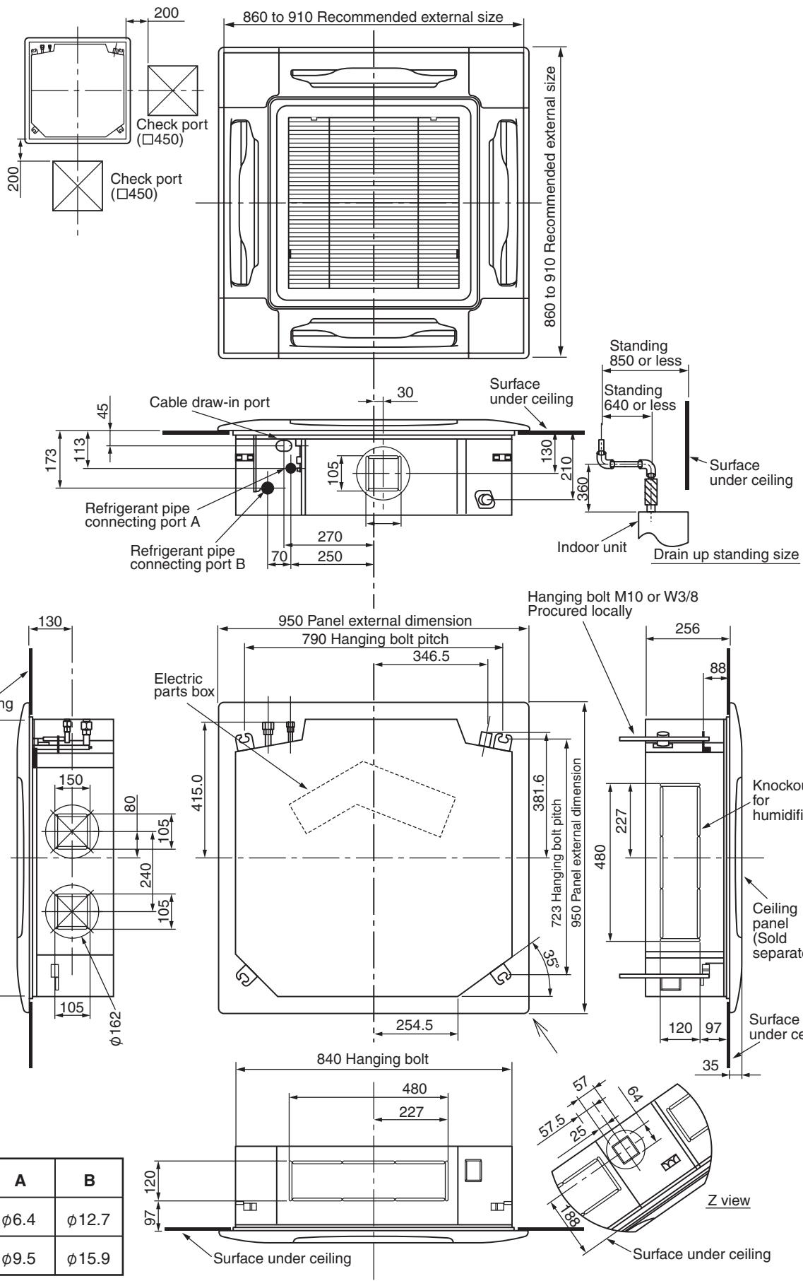
RAV-SM562UT-E, RAV-SM802UT-E
| A | B |
| SM562 | φ6.4 | φ12.7 |
| SM802 | φ9.5 | φ15.9 |
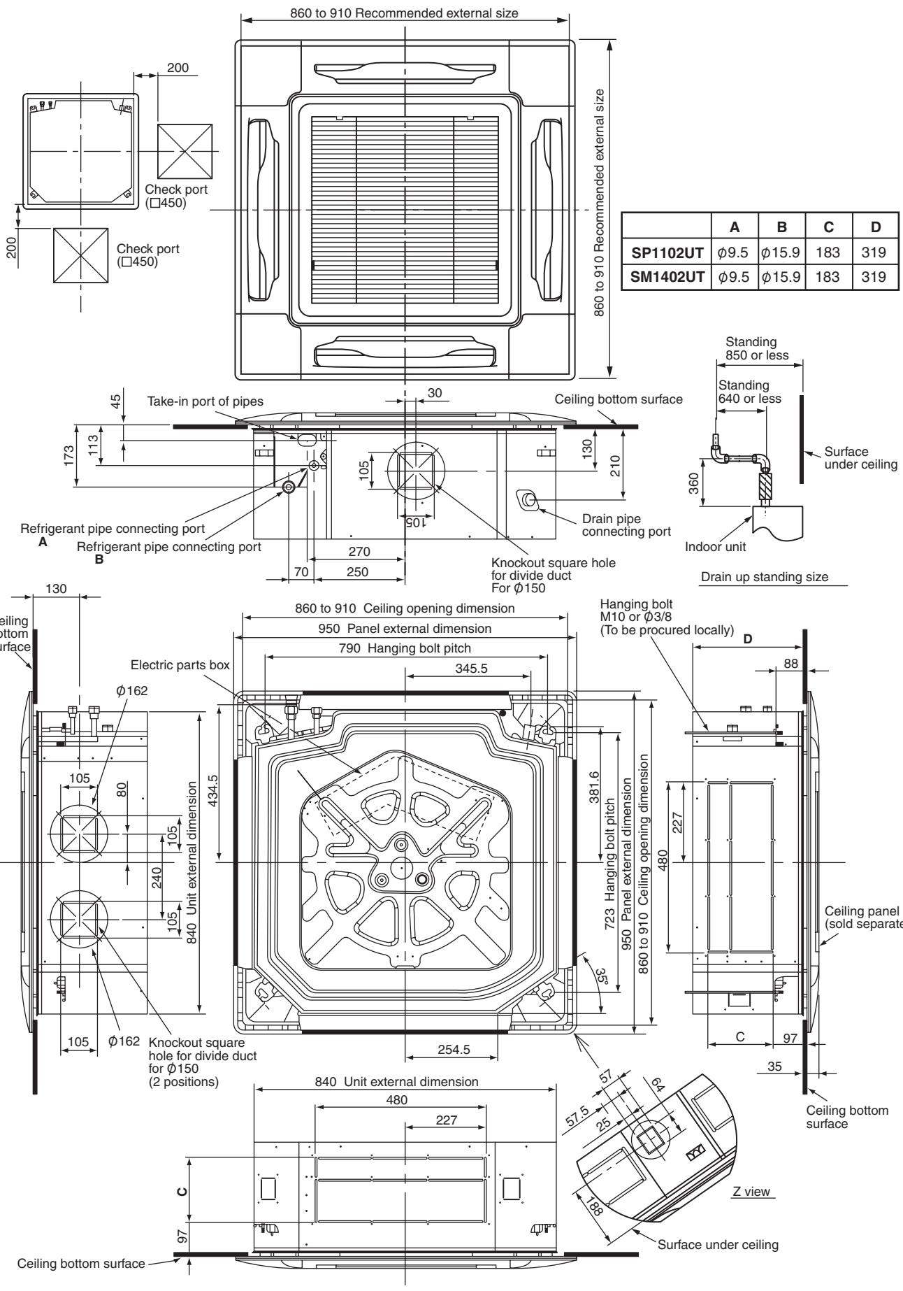
RAV-SP1102UT-E, RAV-SM1402UT-E
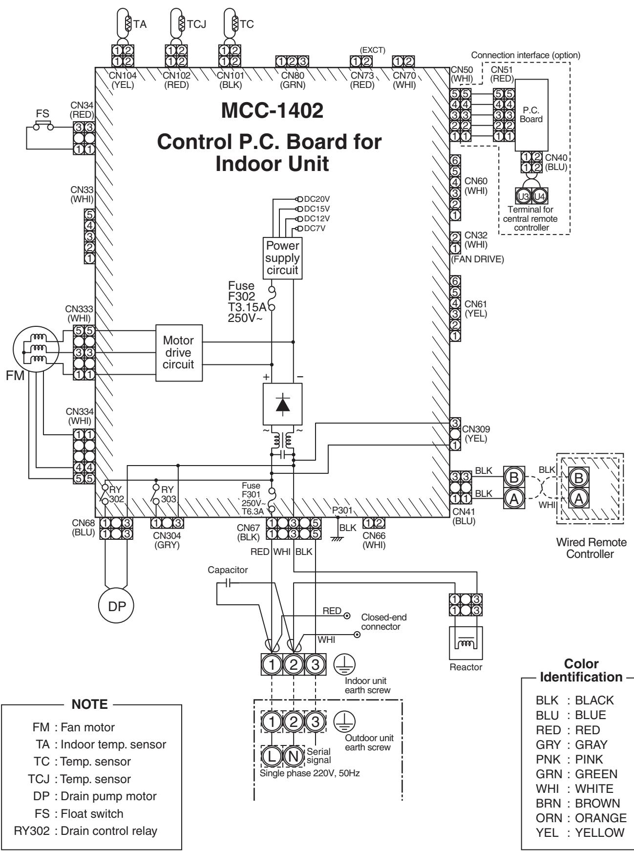
2-1-4. Wiring Diagram
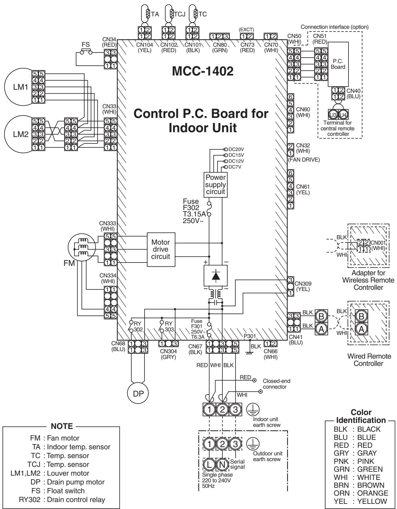
RAV-SM562UT-E, RAV-SM802UT-E, RAV-SP1102UT-E, RAV-SM1402UT-E
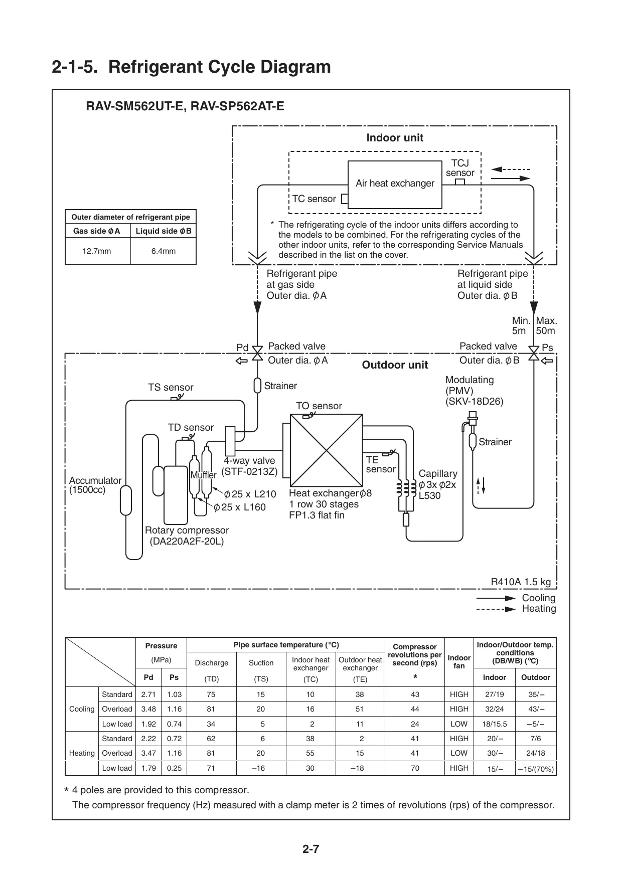
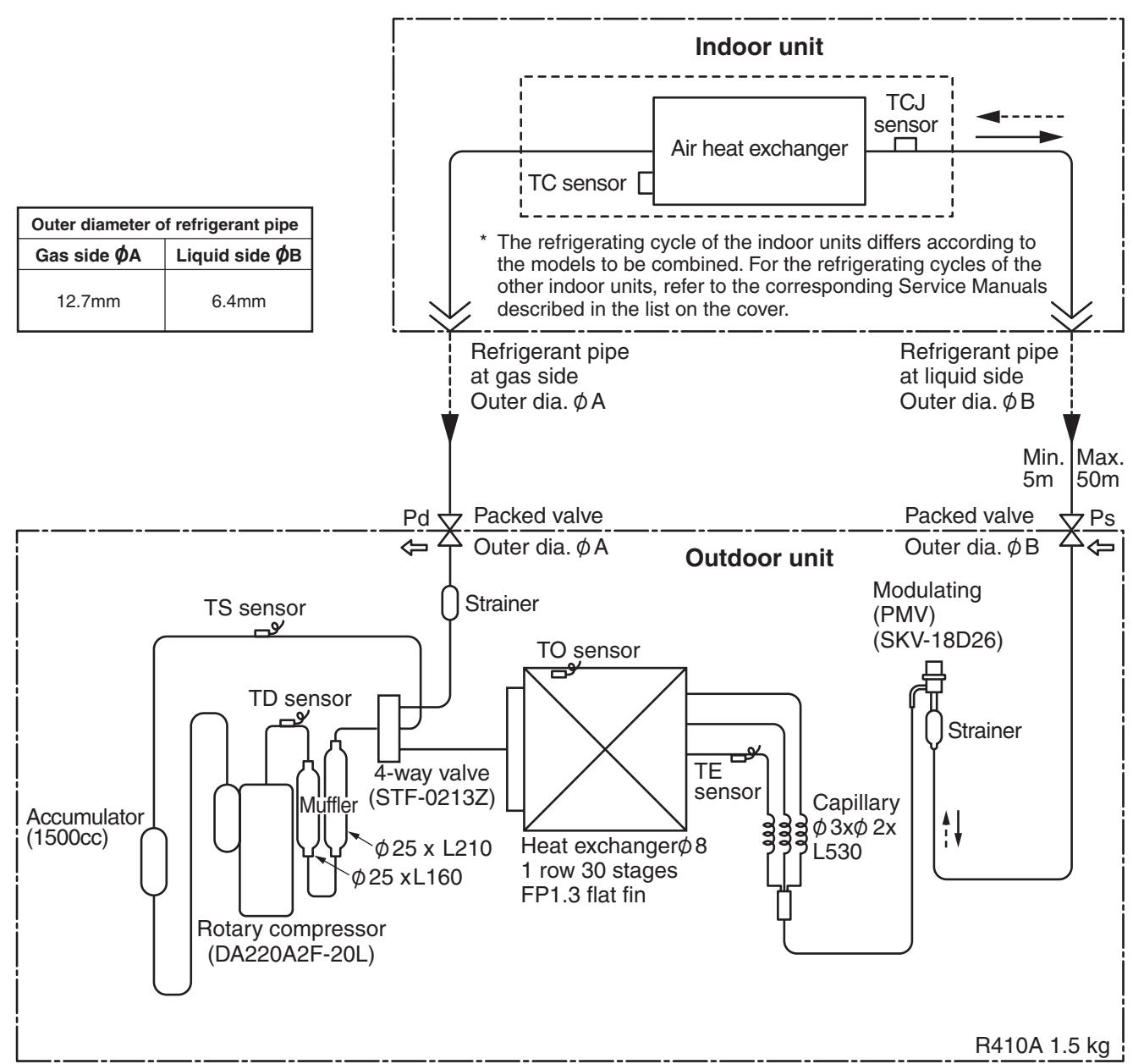
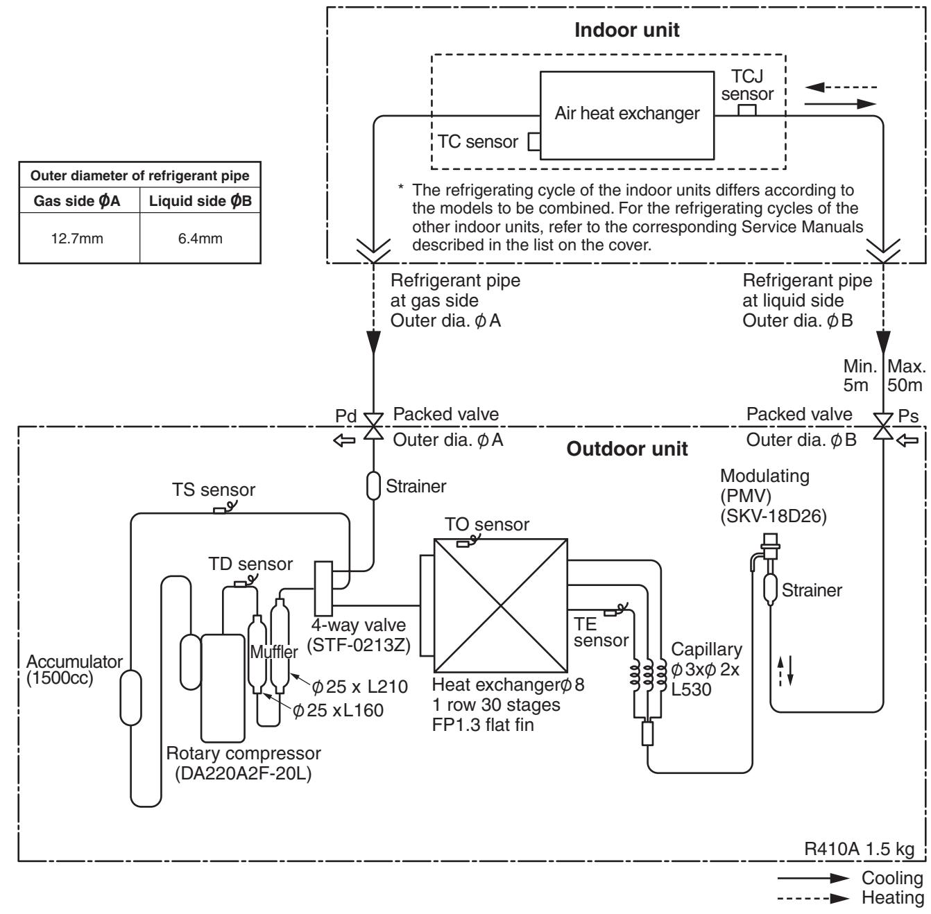
2-1-5. Refrigerant Cycle Diagram
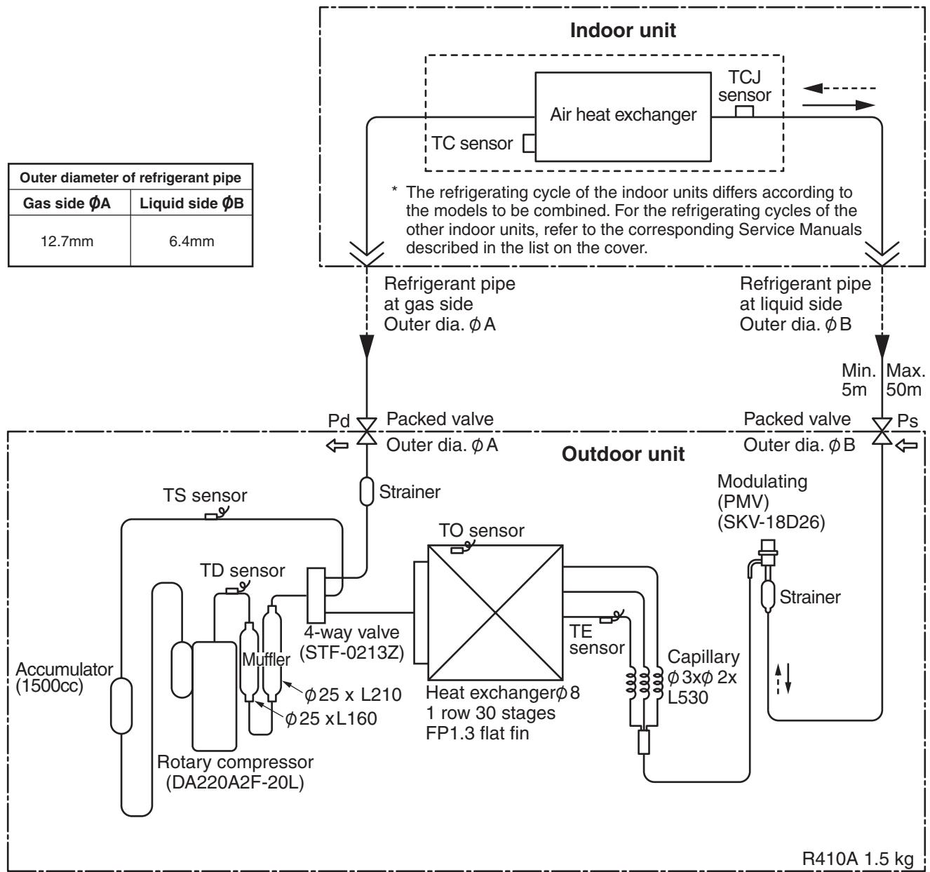
RAV-SM562UT-E, RAV-SP562AT-E
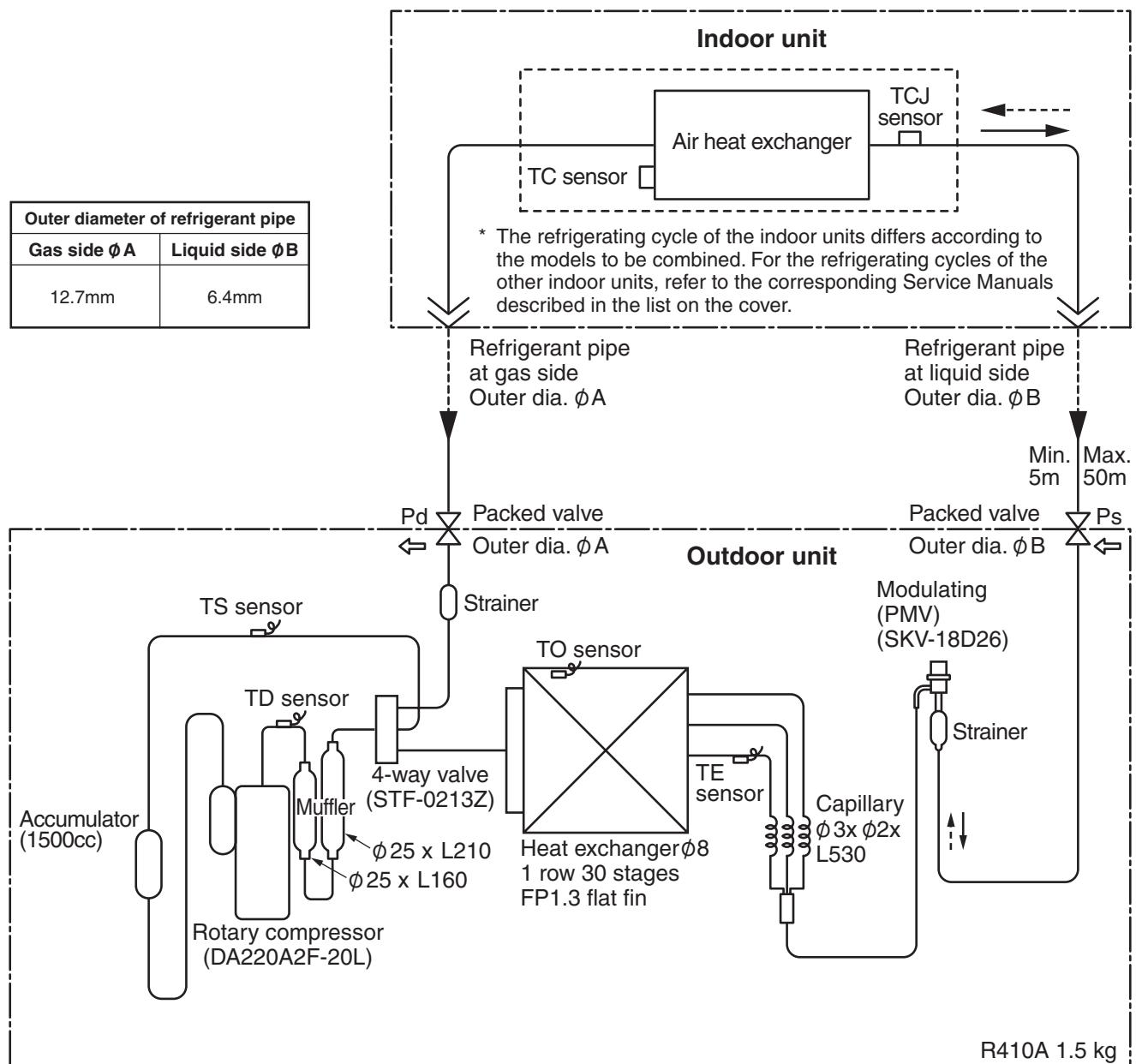
Cooling Heating
| Pressure (MPa) | Pipe surface temperature (℃) | Compressor revolutions per second (rps) * | Indoor fan | Indoor/Outdoor temp. conditions (DB/WB) (℃) |
| Discharge (TD) | Suction (TS) | Indoor heat exchanger (TC) | Outdoor heat exchanger (TE) | Indoor | Outdoor |
| Pd | Ps |
| Cooling | Standard | 2.71 | 1.03 | 75 | 15 | 10 | 38 | 43 | HIGH | 27/19 | 35/- |
| Overload | 3.48 | 1.16 | 81 | 20 | 16 | 51 | 44 | HIGH | 32/24 | 43/- |
| Low load | 1.92 | 0.74 | 34 | 5 | 2 | 11 | 24 | LOW | 18/15.5 | -5/- |
| Heating | Standard | 2.22 | 0.72 | 62 | 6 | 38 | 2 | 41 | HIGH | 20/- | 7/6 |
| Overload | 3.47 | 1.16 | 81 | 20 | 55 | 15 | 41 | LOW | 30/- | 24/18 |
| Low load | 1.79 | 0.25 | 71 | -16 | 30 | -18 | 70 | HIGH | 15/- | -15/(70%) |
- 4 poles are provided to this compressor.
The compressor frequency (Hz) measured with a clamp meter is 2 times of revolutions (rps) of the compressor.
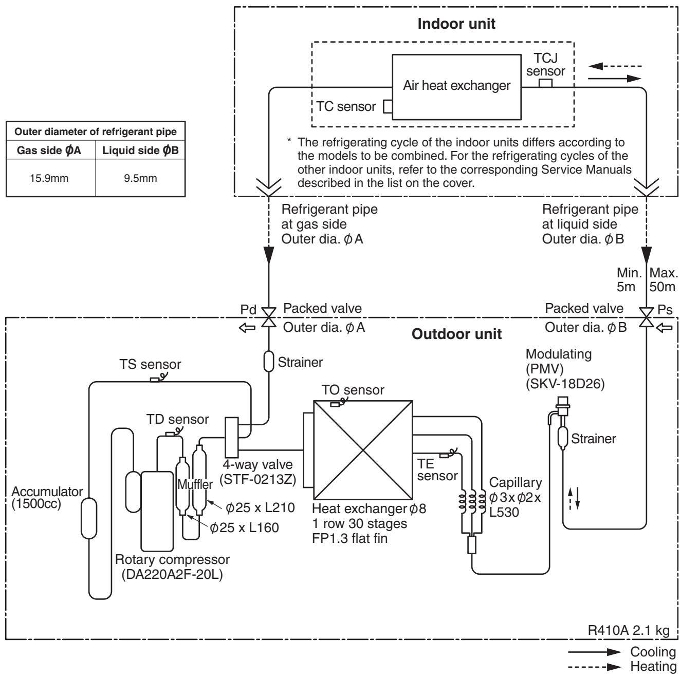
RAV-SM802UT-E, RAV-SP802AT-E

| Pressure (MPa) | Pipe surface temperature (℃) | Compressor revolutions per second (rps) * | Indoor fan | Indoor/Outdoor temp. conditions (DB/WB) (℃) |
| Discharge (TD) | Suction (TS) | Indoor heat exchanger (TC) | Outdoor heat exchanger (TE) | Indoor | Outdoor |
| Pd | Ps |
| Cooling | Standard | 2.72 | 0.93 | 74 | 12 | 11 | 40 | 55 | HIGH | 27/19 | 35/- |
| Overload | 3.57 | 1.10 | 80 | 21 | 17 | 52 | 47 | HIGH | 32/24 | 43/- |
| Low load | 1.89 | 0.74 | 34 | 7 | 2 | 12 | 24 | LOW | 18/15.5 | -5/- |
| Heating | Standard | 2.58 | 0.68 | 72 | 4 | 41 | 2 | 62 | HIGH | 20/- | 7/6 |
| Overload | 3.49 | 1.22 | 79 | 19 | 55 | 16 | 28 | LOW | 30/- | 24/18 |
| Low load | 2.30 | 0.25 | 91 | -17 | 37 | -19 | 90 | HIGH | 15/- | -15/(70%) |
- 4 poles are provided to this compressor.
The compressor frequency (Hz) measured with a clamp meter is 2 times of revolutions (rps) of the compressor.
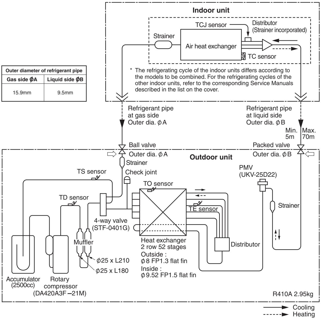
RAV-SP1102UT-E, RAV-SP1102AT-E
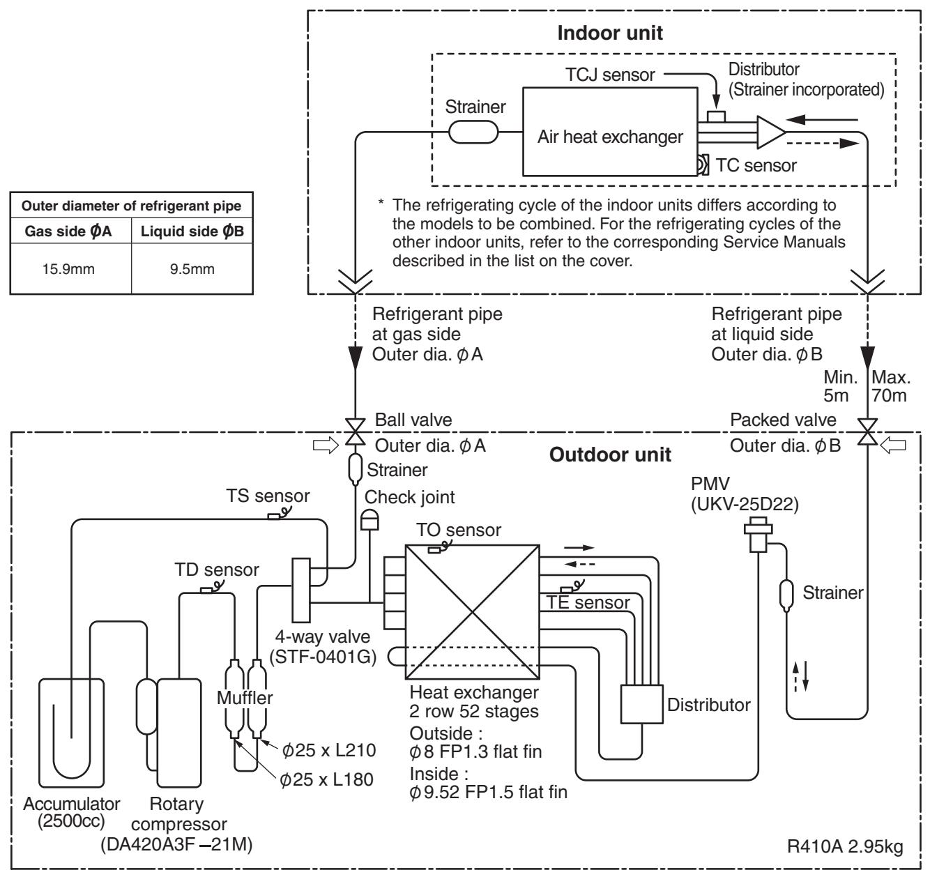
| Pressure (MPa) | Pipe surface temperature (℃) | Compressor revolutions per second (rps) * | Indoor fan | Indoor/Outdoor temp. conditions (DB/WB) (℃) |
| Discharge (TD) | Suction (TS) | Indoor heat exchanger (TC) | Outdoor heat exchanger (TE) | Indoor | Outdoor |
| Pd | Ps |
| Cooling | Standard | 2.55 | 0.98 | 69 | 12 | 10 | 40 | 40 | HIGH | 27/19 | 35/- |
| Overload | 3.28 | 1.08 | 82 | 17 | 16 | 48 | 50 | HIGH | 32/24 | 43/- |
| Low load | 1.76 | 0.76 | 47 | 8 | 5 | 27 | 24 | LOW | 18/15.5 | -5/- |
| Heating | Standard | 2.58 | 0.73 | 68 | 3 | 40 | 3 | 44 | HIGH | 20/- | 7/6 |
| Overload | 3.43 | 1.18 | 75 | 20 | 56 | 16 | 24 | LOW | 30/- | 24/18 |
| Low load | 2.10 | 0.32 | 88 | -14 | 34 | -13 | 63 | HIGH | 15/- | -15/(70%) |
* 4 poles are provided to this compressor. The compressor frequency (Hz) measured with a clamp meter is 2 times of revolutions (rps) of the compressor.
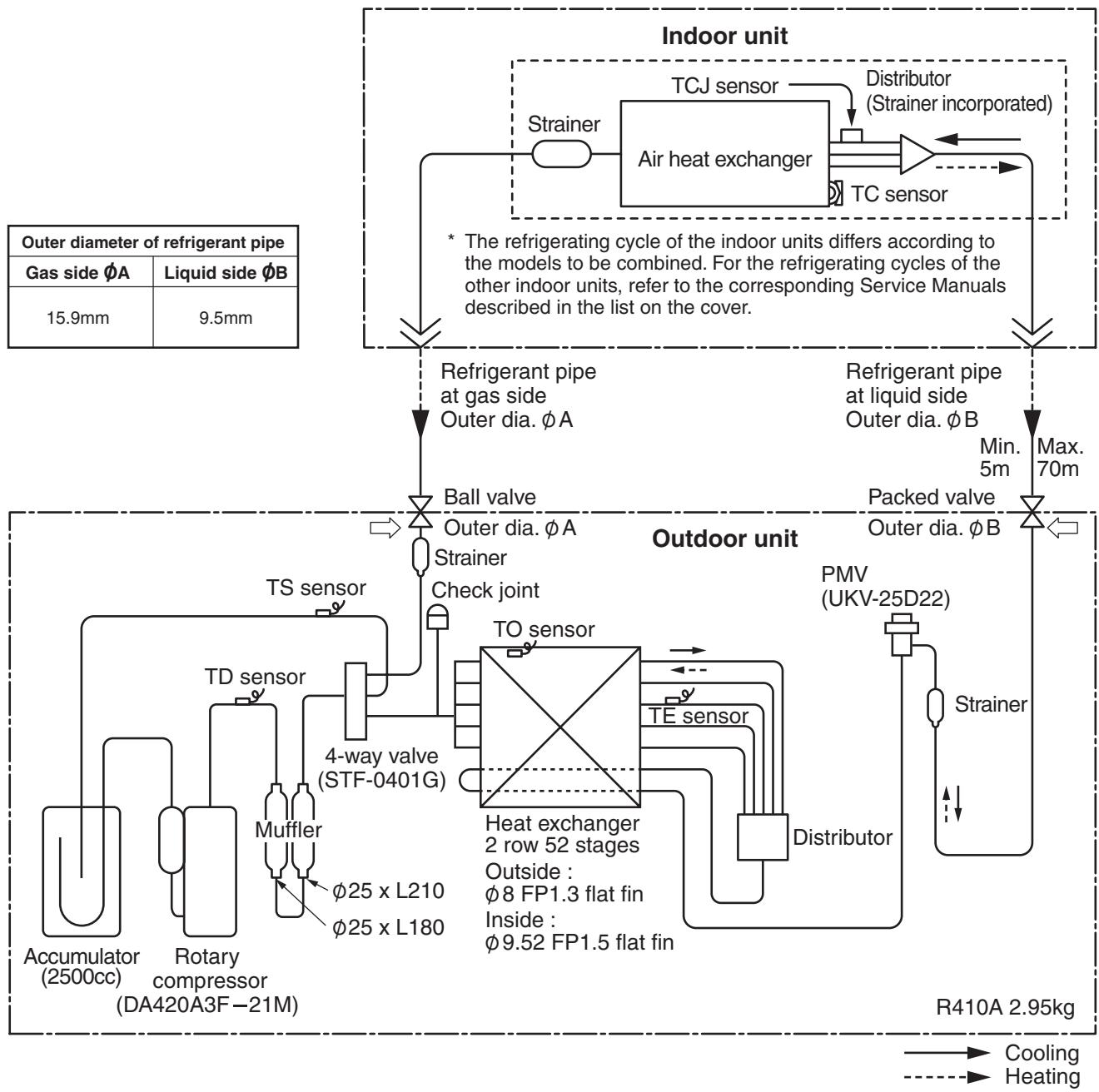
RAV-SM1402UT-E, RAV-SP1402AT-E
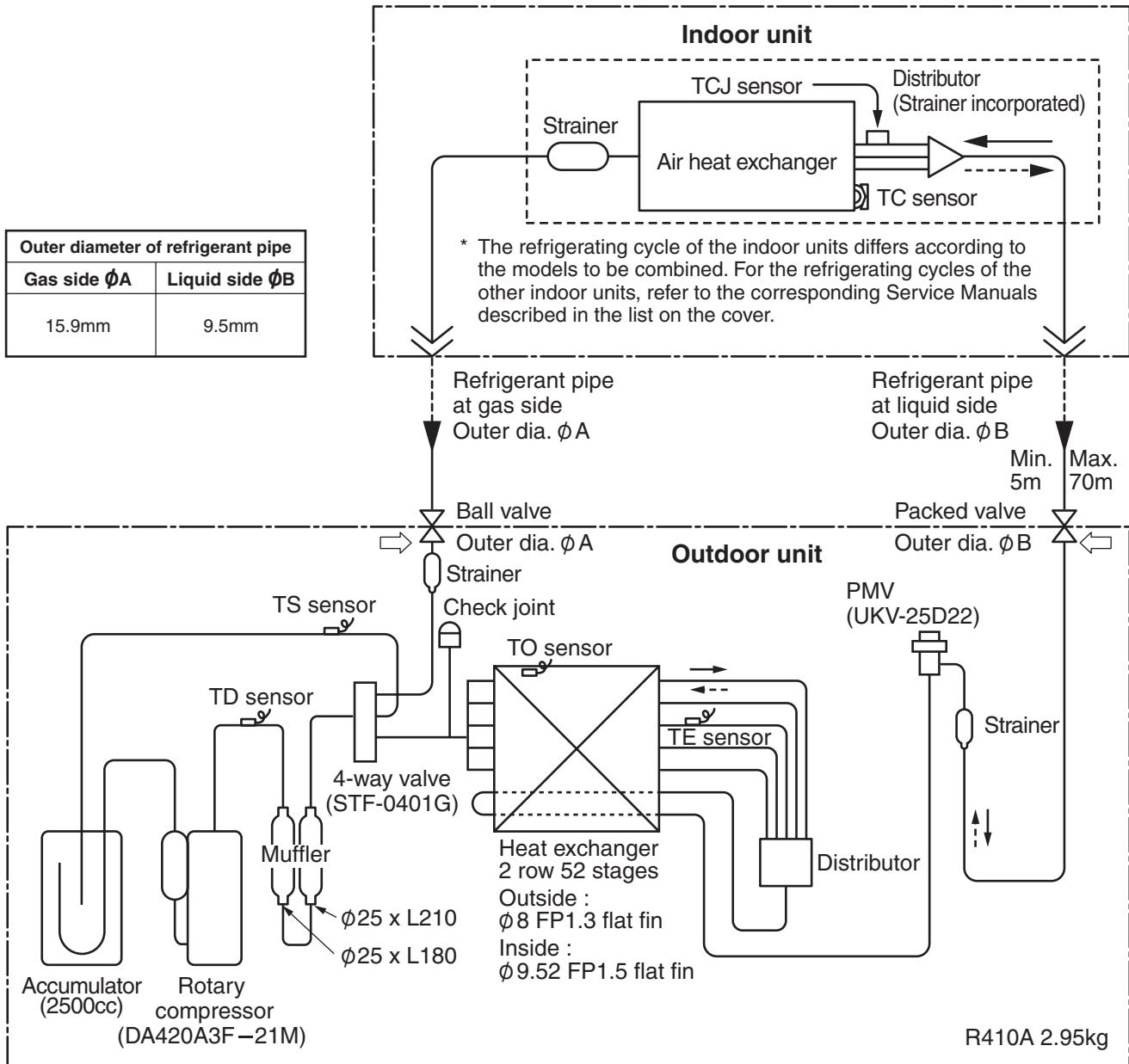
Cooling
Heating
| Pressure (MPa) | Pipe surface temperature (℃) | Compressor revolutions per second (rps) * | Indoor fan | Indoor/Outdoor temp. conditions (DB/WB) (℃) |
| Discharge (TD) | Suction (TS) | Indoor heat exchanger (TC) | Outdoor heat exchanger (TE) | Indoor | Outdoor |
| Pd | Ps |
| Cooling | Standard | 2.76 | 0.91 | 74 | 11 | 9 | 39 | 53 | HIGH | 27/19 | 35/- |
| Overload | 3.46 | 1.03 | 82 | 17 | 16 | 48 | 51 | HIGH | 32/24 | 43/- |
| Low load | 1.77 | 0.78 | 48 | 9 | 6 | 27 | 24 | LOW | 18/15.5 | -5/- |
| Heating | Standard | 2.65 | 0.69 | 75 | 3 | 43 | 3 | 55 | HIGH | 20/- | 7/6 |
| Overload | 3.33 | 1.08 | 74 | 19 | 55 | 15 | 24 | LOW | 30/- | 24/18 |
| Low load | 2.50 | 0.22 | 98 | -22 | 43 | -18 | 73 | HIGH | 15/- | -15/(70%) |
- 4 poles are provided to this compressor.
The compressor frequency (Hz) measured with a clamp meter is 2 times of revolutions (rps) of the compressor.
2-1-6. Sensible Capacity Table
RAV-SM562UT-E, SM802UT-E, SP1102UT-E, SM1402UT-E
| indoor air temp. |
| unit size | outdoor air temp. CDB | 14.0CWB 20.0CDB | 16.0CWB 23.0CDB | 18.0CWB 26.0CDB | 19.0CWB 27.0CDB | 20.0CWB 28.0CDB | 22.0CWB 30.0CDB | 24.0CWB 32.0CDB |
| TC | SHC | TC | SHC | TC | SHC | TC | SHC | TC | SHC | TC | SHC | TC | SHC |
| 562 | 10.0 | 5.0 | 3.5 | 5.5 | 3.8 | 5.9 | 4.1 | 6.1 | 4.2 | 6.2 | 4.4 | 6.6 | 4.6 | 6.9 | 4.8 |
| 12.0 | 4.9 | 3.5 | 5.5 | 3.8 | 5.8 | 4.1 | 6.0 | 4.2 | 6.2 | 4.3 | 6.6 | 4.6 | 6.9 | 4.8 |
| 14.0 | 4.9 | 3.4 | 5.4 | 3.8 | 5.8 | 4.1 | 6.0 | 4.2 | 6.2 | 4.3 | 6.5 | 4.6 | 6.8 | 4.8 |
| 16.0 | 4.9 | 3.4 | 5.4 | 3.8 | 5.8 | 4.0 | 5.9 | 4.1 | 6.1 | 4.3 | 6.5 | 4.5 | 6.8 | 4.7 |
| 18.0 | 4.8 | 3.4 | 5.3 | 3.7 | 5.7 | 4.0 | 5.9 | 4.1 | 6.1 | 4.2 | 6.4 | 4.5 | 6.7 | 4.7 |
| 20.0 | 4.8 | 3.4 | 5.3 | 3.7 | 5.7 | 4.0 | 5.8 | 4.1 | 6.0 | 4.2 | 6.4 | 4.4 | 6.7 | 4.6 |
| 21.0 | 4.8 | 3.3 | 5.3 | 3.7 | 5.7 | 3.9 | 5.8 | 4.1 | 6.0 | 4.2 | 6.3 | 4.4 | 6.6 | 4.6 |
| 23.0 | 4.7 | 3.3 | 5.2 | 3.6 | 5.6 | 3.9 | 5.8 | 4.0 | 5.9 | 4.1 | 6.3 | 4.4 | 6.6 | 4.6 |
| 25.0 | 4.7 | 3.3 | 5.2 | 3.6 | 5.5 | 3.9 | 5.7 | 4.0 | 5.9 | 4.1 | 6.2 | 4.3 | 6.5 | 4.5 |
| 27.0 | 4.6 | 3.2 | 5.1 | 3.6 | 5.5 | 3.8 | 5.6 | 3.9 | 5.8 | 4.0 | 6.1 | 4.3 | 6.4 | 4.5 |
| 29.0 | 4.6 | 3.2 | 5.0 | 3.5 | 5.4 | 3.8 | 5.6 | 3.9 | 5.7 | 4.0 | 6.1 | 4.2 | 6.3 | 4.4 |
| 31.0 | 4.5 | 3.1 | 5.0 | 3.5 | 5.3 | 3.7 | 5.5 | 3.8 | 5.6 | 3.9 | 6.0 | 4.2 | 6.2 | 4.4 |
| 33.0 | 4.4 | 3.1 | 4.9 | 3.4 | 5.2 | 3.7 | 5.4 | 3.8 | 5.5 | 3.9 | 5.9 | 4.1 | 6.1 | 4.3 |
| 35.0 | 4.4 | 3.0 | 4.8 | 3.4 | 5.1 | 3.6 | 5.3 | 3.7 | 5.5 | 3.8 | 5.8 | 4.0 | 6.0 | 4.2 |
| 37.0 | 4.3 | 3.0 | 4.7 | 3.3 | 5.1 | 3.5 | 5.2 | 3.6 | 5.3 | 3.7 | 5.7 | 4.0 | 5.9 | 4.1 |
| 39.0 | 4.2 | 2.9 | 4.6 | 3.2 | 4.9 | 3.5 | 5.1 | 3.6 | 5.2 | 3.7 | 5.5 | 3.9 | 5.8 | 4.1 |
| 802 | 10.0 | 6.7 | 4.6 | 7.4 | 5.1 | 7.9 | 5.4 | 8.1 | 5.6 | 8.3 | 5.8 | 8.8 | 6.1 | 9.2 | 6.4 |
| 12.0 | 6.6 | 4.6 | 7.3 | 5.0 | 7.8 | 5.4 | 8.1 | 5.6 | 8.3 | 5.7 | 8.8 | 6.1 | 9.2 | 6.3 |
| 14.0 | 6.6 | 4.5 | 7.3 | 5.0 | 7.8 | 5.4 | 8.0 | 5.5 | 8.2 | 5.7 | 8.7 | 6.0 | 9.1 | 6.3 |
| 16.0 | 6.5 | 4.5 | 7.2 | 5.0 | 7.7 | 5.3 | 8.0 | 5.5 | 8.2 | 5.6 | 8.7 | 6.0 | 9.1 | 6.3 |
| 18.0 | 6.5 | 4.5 | 7.2 | 4.9 | 7.7 | 5.3 | 7.9 | 5.4 | 8.1 | 5.6 | 8.6 | 5.9 | 9.0 | 6.2 |
| 20.0 | 6.4 | 4.4 | 7.1 | 4.9 | 7.6 | 5.3 | 7.8 | 5.4 | 8.1 | 5.6 | 8.5 | 5.9 | 8.9 | 6.2 |
| 21.0 | 6.4 | 4.4 | 7.1 | 4.9 | 7.6 | 5.2 | 7.8 | 5.4 | 8.0 | 5.5 | 8.5 | 5.9 | 8.9 | 6.1 |
| 23.0 | 6.3 | 4.4 | 7.0 | 4.8 | 7.5 | 5.2 | 7.7 | 5.3 | 7.9 | 5.5 | 8.4 | 5.8 | 8.8 | 6.1 |
| 25.0 | 6.3 | 4.3 | 6.9 | 4.8 | 7.4 | 5.1 | 7.6 | 5.3 | 7.9 | 5.4 | 8.3 | 5.7 | 8.7 | 6.0 |
| 27.0 | 6.2 | 4.3 | 6.8 | 4.7 | 7.3 | 5.1 | 7.5 | 5.2 | 7.8 | 5.4 | 8.2 | 5.7 | 8.6 | 5.9 |
| 29.0 | 6.1 | 4.2 | 6.7 | 4.7 | 7.2 | 5.0 | 7.4 | 5.1 | 7.7 | 5.3 | 8.1 | 5.6 | 8.5 | 5.9 |
| 31.0 | 6.0 | 4.2 | 6.7 | 4.6 | 7.1 | 4.9 | 7.3 | 5.1 | 7.5 | 5.2 | 8.0 | 5.5 | 8.4 | 5.8 |
| 33.0 | 5.9 | 4.1 | 6.5 | 4.5 | 7.0 | 4.8 | 7.2 | 5.0 | 7.4 | 5.1 | 7.9 | 5.4 | 8.2 | 5.7 |
| 35.0 | 5.8 | 4.0 | 6.4 | 4.4 | 6.9 | 4.8 | 7.1 | 4.9 | 7.3 | 5.0 | 7.7 | 5.3 | 8.1 | 5.6 |
| 37.0 | 5.7 | 3.9 | 6.3 | 4.4 | 6.8 | 4.7 | 7.0 | 4.8 | 7.2 | 4.9 | 7.6 | 5.2 | 7.9 | 5.5 |
| 39.0 | 5.6 | 3.9 | 6.2 | 4.3 | 6.6 | 4.6 | 6.8 | 4.7 | 7.0 | 4.8 | 7.4 | 5.1 | 7.8 | 5.4 |
| 1102 | 10.0 | 9.4 | 7.0 | 10.4 | 7.4 | 11.1 | 7.9 | 11.4 | 7.9 | 11.8 | 7.9 | 12.5 | 7.8 | 13.0 | 7.6 |
| 12.0 | 9.3 | 6.9 | 10.3 | 7.4 | 11.0 | 7.9 | 11.4 | 7.8 | 11.7 | 7.8 | 12.4 | 7.7 | 12.9 | 7.6 |
| 14.0 | 9.3 | 6.9 | 10.2 | 7.3 | 11.0 | 7.8 | 11.3 | 7.8 | 11.6 | 7.8 | 12.3 | 7.7 | 12.9 | 7.5 |
| 16.0 | 9.2 | 6.8 | 10.2 | 7.3 | 10.9 | 7.8 | 11.2 | 7.7 | 11.5 | 7.7 | 12.2 | 7.6 | 12.8 | 7.5 |
| 18.0 | 9.1 | 6.8 | 10.1 | 7.2 | 10.8 | 7.7 | 11.1 | 7.7 | 11.4 | 7.7 | 12.1 | 7.6 | 12.7 | 7.4 |
| 20.0 | 9.1 | 6.7 | 10.0 | 7.2 | 10.7 | 7.6 | 11.0 | 7.6 | 11.3 | 7.6 | 12.0 | 7.5 | 12.6 | 7.4 |
| 21.0 | 9.0 | 6.7 | 10.0 | 7.1 | 10.7 | 7.6 | 11.0 | 7.6 | 11.3 | 7.6 | 12.0 | 7.5 | 12.5 | 7.3 |
| 23.0 | 8.9 | 6.6 | 9.9 | 7.1 | 10.6 | 7.5 | 10.9 | 7.5 | 11.2 | 7.5 | 11.8 | 7.4 | 12.4 | 7.3 |
| 25.0 | 8.8 | 6.6 | 9.8 | 7.0 | 10.4 | 7.4 | 10.8 | 7.4 | 11.1 | 7.4 | 11.7 | 7.3 | 12.2 | 7.2 |
| 27.0 | 8.7 | 6.5 | 9.6 | 6.9 | 10.3 | 7.3 | 10.6 | 7.3 | 10.9 | 7.3 | 11.6 | 7.2 | 12.1 | 7.1 |
| 29.0 | 8.6 | 6.4 | 9.5 | 6.8 | 10.2 | 7.2 | 10.5 | 7.2 | 10.8 | 7.2 | 11.4 | 7.1 | 11.9 | 7.0 |
| 31.0 | 8.5 | 6.3 | 9.4 | 6.7 | 10.0 | 7.1 | 10.3 | 7.1 | 10.6 | 7.1 | 11.3 | 7.0 | 11.8 | 6.9 |
| 33.0 | 8.4 | 6.2 | 9.2 | 6.6 | 9.9 | 7.0 | 10.2 | 7.0 | 10.5 | 7.0 | 11.1 | 6.9 | 11.6 | 6.8 |
| 35.0 | 8.2 | 6.1 | 9.1 | 6.5 | 9.7 | 6.9 | 10.0 | 6.9 | 10.3 | 6.9 | 10.9 | 6.8 | 11.4 | 6.7 |
| 37.0 | 8.1 | 6.0 | 8.9 | 6.4 | 9.5 | 6.8 | 9.8 | 6.8 | 10.1 | 6.8 | 10.7 | 6.7 | 11.2 | 6.5 |
| 39.0 | 7.9 | 5.9 | 8.7 | 6.3 | 9.3 | 6.6 | 9.6 | 6.6 | 9.9 | 6.6 | 10.5 | 6.5 | 10.9 | 6.4 |
| 1402 | 10.0 | 11.7 | 8.5 | 13.0 | 9.1 | 13.9 | 9.6 | 14.3 | 9.6 | 14.7 | 9.6 | 15.6 | 9.5 | 16.3 | 9.3 |
| 12.0 | 11.7 | 8.4 | 12.9 | 9.0 | 13.8 | 9.6 | 14.2 | 9.5 | 14.6 | 9.5 | 15.5 | 9.4 | 16.2 | 9.2 |
| 14.0 | 11.6 | 8.4 | 12.8 | 8.9 | 13.7 | 9.5 | 14.1 | 9.5 | 14.5 | 9.5 | 15.4 | 9.4 | 16.1 | 9.2 |
| 16.0 | 11.5 | 8.3 | 12.7 | 8.9 | 13.6 | 9.4 | 14.0 | 9.4 | 14.4 | 9.4 | 15.3 | 9.3 | 16.0 | 9.1 |
| 18.0 | 11.4 | 8.3 | 12.6 | 8.8 | 13.5 | 9.4 | 13.9 | 9.3 | 14.3 | 9.3 | 15.1 | 9.2 | 15.8 | 9.0 |
| 20.0 | 11.3 | 8.2 | 12.5 | 8.7 | 13.4 | 9.3 | 13.8 | 9.3 | 14.2 | 9.3 | 15.0 | 9.2 | 15.7 | 9.0 |
| 21.0 | 11.3 | 8.2 | 12.4 | 8.7 | 13.3 | 9.2 | 13.7 | 9.2 | 14.1 | 9.2 | 15.0 | 9.1 | 15.6 | 8.9 |
| 23.0 | 11.2 | 8.1 | 12.3 | 8.6 | 13.2 | 9.2 | 13.6 | 9.1 | 14.0 | 9.1 | 14.8 | 9.0 | 15.5 | 8.8 |
| 25.0 | 11.0 | 8.0 | 12.2 | 8.5 | 13.1 | 9.1 | 13.4 | 9.0 | 13.8 | 9.0 | 14.6 | 8.9 | 15.3 | 8.7 |
| 27.0 | 10.9 | 7.9 | 12.0 | 8.4 | 12.9 | 8.9 | 13.3 | 8.9 | 13.7 | 8.9 | 14.5 | 8.8 | 15.1 | 8.6 |
| 29.0 | 10.8 | 7.8 | 11.9 | 8.3 | 12.7 | 8.8 | 13.1 | 8.8 | 13.5 | 8.8 | 14.3 | 8.7 | 14.9 | 8.5 |
| 31.0 | 10.6 | 7.7 | 11.7 | 8.2 | 12.5 | 8.7 | 12.9 | 8.7 | 13.3 | 8.7 | 14.1 | 8.6 | 14.7 | 8.4 |
| 33.0 | 10.4 | 7.6 | 11.5 | 8.1 | 12.3 | 8.6 | 12.7 | 8.5 | 13.1 | 8.5 | 13.8 | 8.4 | 14.5 | 8.3 |
| 35.0 | 10.3 | 7.4 | 11.3 | 7.9 | 12.1 | 8.4 | 12.5 | 8.4 | 12.9 | 8.4 | 13.6 | 8.3 | 14.2 | 8.1 |
| 37.0 | 10.1 | 7.3 | 11.1 | 7.8 | 11.9 | 8.3 | 12.3 | 8.2 | 12.6 | 8.2 | 13.4 | 8.1 | 14.0 | 8.0 |
| 39.0 | 9.9 | 7.1 | 10.9 | 7.6 | 11.7 | 8.1 | 12.0 | 8.1 | 12.4 | 8.1 | 13.1 | 8.0 | 13.7 | 7.8 |
TC:Total Capacity [kW]
SHC:Sensible Heat Capacity [kW]
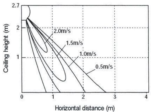
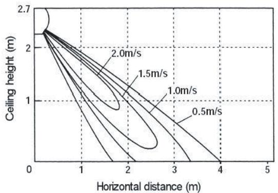
2-1-7. Air Throw Distance Chart
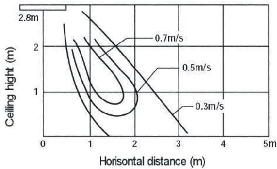
RAV-SM562UT-E
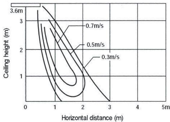
RAV-SM802UT-E
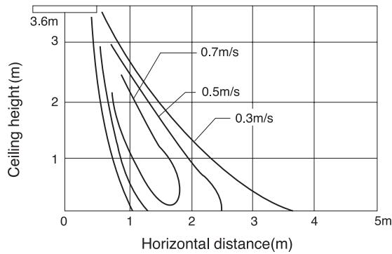
RAV-SM1402UT-E
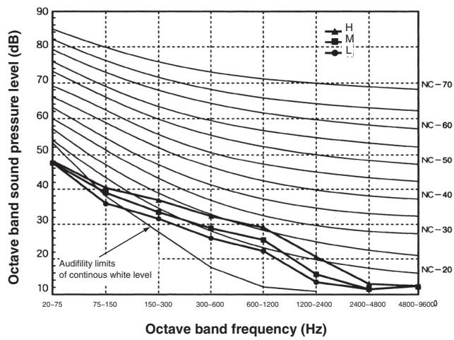
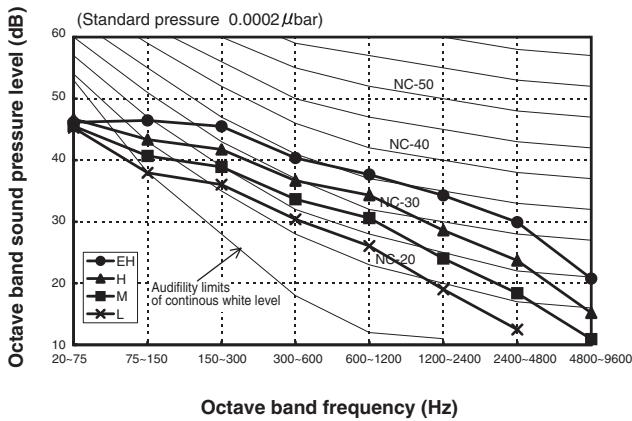
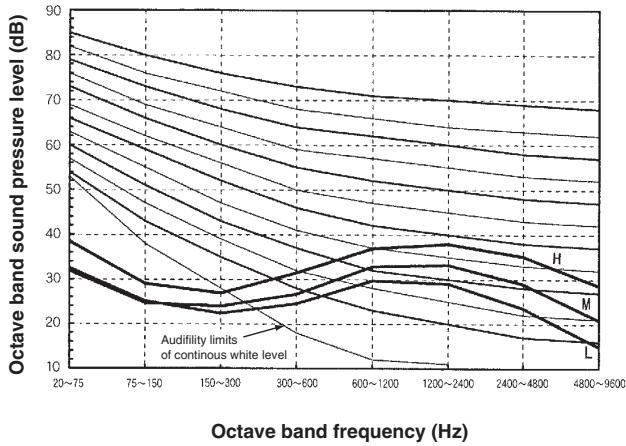
2-1-8. Sound Characteristics (NC curve)
RAV-SM562UT-E
| Fan tap | H | M | L |
| Sound pressure level (dB(A)) | 32 | 29 | 27 |
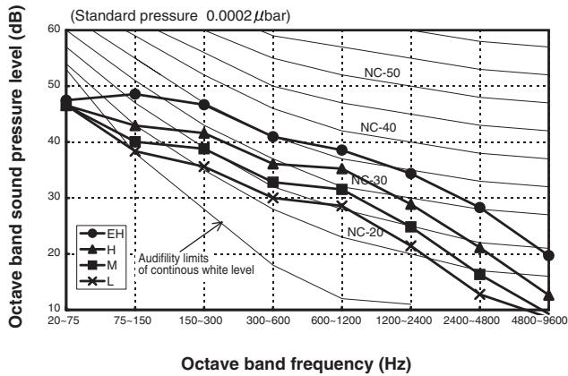
RAV-SM802UT-E
| Fan tap | H | M | L |
| Sound pressure level (dB(A)) | 34 | 31 | 28 |
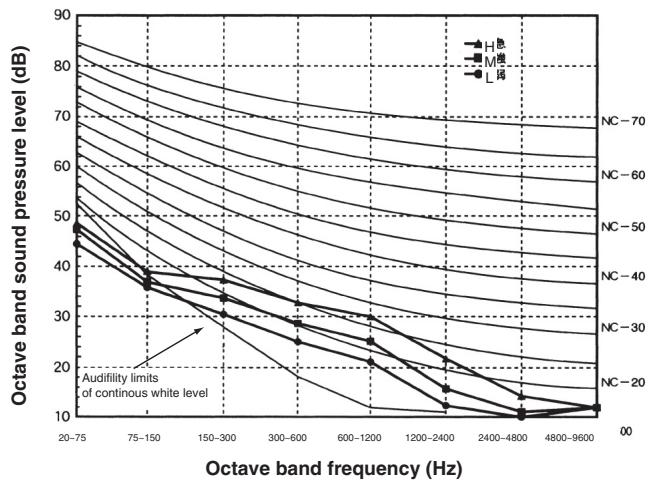
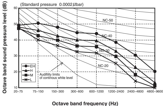
RAV-SM1402UT-E
| Fan tap | H | M | L |
| Sound pressure level (dB(A)) | 42 | 38 | 34 |
2-2. Duct type
2-2-1. Single system Specifications 2-15
2-2-2. Twin system specifications 2-16
2-2-3. Dimension 2-17
2-2-4. Wiring diagram 2-18
2-2-5. Refrigerant cycle diagram 2-19
2-2-6. Sensible capacity table 2-23
2-2-7. Fan static 2-24
2-2-8. Sound characteristics 2-26
2-2. Duct Type
2-2-1. Single System Specifications
| Model | Indoor unit RAV- | SM562BT-E | SM802BT-E | SM1102BT-E | SM1402BT-E |
| Outdoor unit RAV- | SP562AT-E | SP802AT-E | SP1102AT-E | SP1402AT-E |
| Cooling capacity | (kW) | 5.0 | 7.1 | 10.0 | 12.5 |
| Heating capacity | (kW) | 5.6 | 8.0 | 11.2 | 14.0 |
| Power supply | 1 phase 230V (220 - 240V) 50Hz |
| Electrical characteristics | Cooling | Running current (A) | 6.51 - 5.97 | 9.74 - 8.93 | 11.72 - 10.74 | 18.09 - 16.58 |
| Power consumption (kW) | 1.39 | 2.10 | 2.50 | 3.90 |
| Power factor (%) | 97 | 98 | 97 | 98 |
| EER (W/W) | 3.60 | 3.38 | 4.00 | 3.21 |
| Energy efficiency class * | A | A | A | A |
| Energy rating ** | — | — | — | — |
| Heating | Running current (A) | 7.26 - 6.66 | 9.74 - 8.93 | 11.72 - 10.74 | 16.70 - 15.31 |
| Power consumption (kW) | 1.55 | 2.10 | 2.50 | 3.60 |
| Power factor (%) | 97 | 98 | 97 | 98 |
| COP (W/W) | 3.61 | 3.81 | 4.48 | 3.89 |
| Energy efficiency class * | A | A | A | A |
| Energy rating ** | — | — | — | — |
| Appearance | Main unit | Zinc hot dipping steel plate |
| Ceiling panel (Sold separately) | Model | — |
| Panel color | — |
| Outer dimension | Main unit | Height (mm) | 320 | 320 | 320 | 320 |
| Width (mm) | 700 | 1000 | 1350 | 1350 |
| Depth (mm) | 800 | 800 | 800 | 800 |
| Ceiling panel (Sold separately) | Height (mm) | — | — | — | — |
| Width (mm) | — | — | — | — |
| Depth (mm) | — | — | — | — |
| Total weight | Main unit (kg) | 30 | 39 | 54 | 54 |
| Ceiling panel (Sold separately) (kg) | — | — | — | — |
| Heat exchanger | Finned tube |
| Fan unit | Fan | Centrifugal | Centrifugal | Centrifugal | Centrifugal |
| Standard air flow | H/M/L (m³/min) | 13.0/11.9/9.8 | 19.0/16.2/13.3 | 27.0/23.0/18.9 | 33.0/28.0/23.1 |
| Motor (W) | 120 | 120 | 120 | 120 |
| Air filter | TCB- | UFM21BE UFM61BE | UFM11BFCE UFM31BE UFH51BFCE UFM71BE | UFM21BFCE UFM 41BE UFH61BFCE UFH 81BE |
| Controller (Sold separately) | RBC-AMT31E2, AS21E2, TCB-SC642TLE2, AX21E2 |
| Connecting pipe | Gas side (mm) | 12.7 | 15.9 | 15.9 | 15.9 |
| Liquid side (mm) | 6.4 | 9.5 | 9.5 | 9.5 |
| Drain port (mm) | VP25 |
| Sound pressure level | H/M/L (dB·A) | 40/37/33 | 40/37/34 | 42/39/36 | 44/41/38 |
| Sound power level | H/M/L (dB·A) | 55/52/48 | 55/52/49 | 57/54/51 | 59/56/53 |
: IEC standard, *: AS standard
2-2-2. Twin System Specifications
| Model | Type | Concealed Duct |
| Indoor unit 1 RAV- | SM562BT-E | SM802BT-E |
| Indoor unit 2 RAV- | SM562BT-E | SM802BT-E |
| Outdoor unit RAV- | SP1102AT-E | SP1402AT-E |
| Cooling capacity (kW) | 10.0 | 12.5 |
| Heating capacity (kW) | 11.2 | 14.0 |
| Indoor unit |
| Power supply | 1 phase 230V (220 - 240V) 50Hz |
| Electrical characteristics | Cooling | Running current (A) | 11.72-10.74 | 18.09-16.58 |
| Power consumption (kW) | 2.50 | 3.90 |
| Powerfactor (%) | 97 | 98 |
| EER (W/W) | 4.00 | 3.21 |
| Energy efficiency class * | A | A |
| Heating | Running current (A) | 11.95-10.95 | 16.70-15.31 |
| Power consumption (kW) | 2.55 | 3.60 |
| Powerfactor (%) | 97 | 98 |
| COP (W/W) | 4.39 | 3.89 |
| Energy efficiency class * | A | A |
| Fan unit | Fan | Centrifugal | Centrifugal |
| Standard air flow | H/M/L (m³/min) | 13.0/11.9/9.8 | 19.0/16.2/13.3 |
| Motor (W) | 120 | 120 |
| Sound pressure level | H/M/L (dB·A) | 40/37/33 | 40/37/34 |
| Sound power level | H/M/L (dB·A) | 55/52/48 | 55/52/49 |
| Outdoor unit |
| Power supply | 1 phase 230V (220 - 240V) 50Hz (Power exclusive to outdoor is required.) |
| Inter connecting pipes | Standard length (m) | 7.5 | 7.5 |
| Min. length (m) | 5.0 | 5.0 |
| Max. total length (m) | 50 | 50 |
| Over 30m | 40g/m (31m to 50m) |
| Height difference | Outdoor lower (m) | 30 | 30 |
| Outdoor high (m) | 30 | 30 |
| Fan unit | Fan | Propeller fan |
| Standard air flow high (m³/min) | 125 | 125 |
| Motor (W) | 63 + 63 | 63 + 63 |
| Connecting pipe | Gas side | Main (mm) | 15.9 | 15.9 |
| Sub (mm) | 12.7 | 15.9 |
| Liquid side | Main (mm) | 9.5 | 9.5 |
| Sub (mm) | 6.4 | 9.5 |
| Sound pressure level | Cooling/Heating (dB·A) | 49/51 | 53/54 |
| Sound power level | Cooling/Heating (dB·A) | 66/68 | 70/71 |
2-2-3. Dimension
RAV-SM562BT-E, RAV-SM802BT-E, RAV-SM1102BT-E, RAV-SM1402BT-E
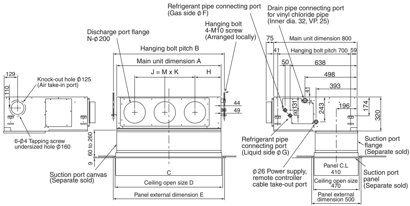
| A | B | C | D | E | F | G | H | J | K | M | N | O |
| RAV-SM562BT | 700 | 766 | 690 | 750 | 780 | 12.7 | 6.4 | 252 | 280 | 280 | 1 | 2 | 410 |
| RAV-SM802BT | 1000 | 1066 | 990 | 1050 | 1080 | 15.9 | 9.5 | 252 | 580 | 290 | 2 | 3 | 410 |
| RAV-SM1102BTRAV-SM1402BT | 1350 | 1416 | 1340 | 1400 | 1430 | 15.9 | 9.5 | 252 | 930 | 310 | 3 | 4 | 410 |
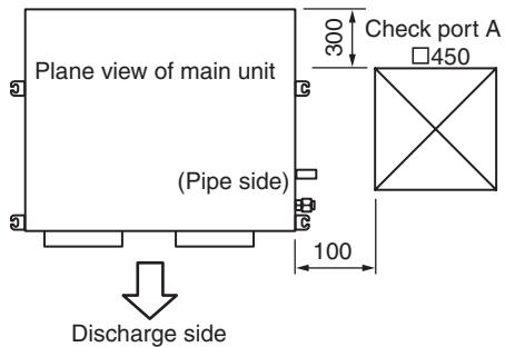
NOTE 1 :
For maintenance of the equipment, be sure to install a check port A at the position as shown below.
NOTE 2 :
Using the drain up kit sold separately, drain-up by 300 (mm) from drain pipe draw-out port of the main unit is necessary. The drain-up over 300mm or more is impossible.
2-2-4. Wiring diagram
RAV-SM562BT-E, RAV-SM802BT-E, RAV-SM1102BT-E, RAV-SM1402BT-E
2-2-5. Refrigerant Cycle Diagram
RAV-SM562BT-E, RAV-SP562AT-E
Cooling Heating
| Pressure (MPa) | Pipe surface temperature (℃) | Compressor revolutions per second (rps) * | Indoor fan | Indoor/Outdoor temp. conditions (DB/WB) (℃) |
| Discharge (TD) | Suction (TS) | Indoor heat exchanger (TC) | Outdoor heat exchanger (TE) | Indoor | Outdoor |
| Pd | Ps |
| Cooling | Standard | 2.71 | 1.03 | 75 | 15 | 10 | 38 | 43 | HIGH | 27/19 | 35/- |
| Overload | 3.48 | 1.16 | 81 | 20 | 16 | 51 | 44 | HIGH | 32/24 | 43/- |
| Low load | 1.92 | 0.74 | 34 | 5 | 2 | 11 | 24 | LOW | 18/15.5 | -5/- |
| Heating | Standard | 2.22 | 0.72 | 62 | 6 | 38 | 2 | 41 | HIGH | 20/- | 7/6 |
| Overload | 3.47 | 1.16 | 81 | 20 | 55 | 15 | 41 | LOW | 30/- | 24/18 |
| Low load | 1.79 | 0.25 | 71 | -16 | 30 | -18 | 70 | HIGH | 15/- | -15/(70%) |
- 4 poles are provided to this compressor. The compressor frequency (Hz) measured with a clamp meter is 2 times of revolutions (rps) of the compressor.
RAV-SM802BT-E, RAV-SP802AT-E

| Pressure (MPa) | Pipe surface temperature (℃) | Compressor revolutions per second (rps) * | Indoor fan | Indoor/Outdoor temp. conditions (DB/WB) (℃) |
| Discharge (TD) | Suction (TS) | Indoor heat exchanger (TC) | Outdoor heat exchanger (TE) | Indoor | Outdoor |
| Pd | Ps |
| Cooling | Standard | 2.72 | 0.93 | 74 | 12 | 11 | 40 | 55 | HIGH | 27/19 | 35/- |
| Overload | 3.57 | 1.10 | 80 | 21 | 17 | 52 | 47 | HIGH | 32/24 | 43/- |
| Low load | 1.89 | 0.74 | 34 | 7 | 2 | 12 | 24 | LOW | 18/15.5 | -5/- |
| Heating | Standard | 2.58 | 0.68 | 72 | 4 | 41 | 2 | 62 | HIGH | 20/- | 7/6 |
| Overload | 3.49 | 1.22 | 79 | 19 | 55 | 16 | 28 | LOW | 30/- | 24/18 |
| Low load | 2.30 | 0.25 | 91 | -17 | 37 | -19 | 90 | HIGH | 15/- | -15/(70%) |
- 4 poles are provided to this compressor. The compressor frequency (Hz) measured with a clamp meter is 2 times of revolutions (rps) of the compressor.
RAV-SM1102BT-E, RAV-SP1102AT-E

| Pressure (MPa) | Pipe surface temperature (℃) | Compressor revolutions per second (rps) * | Indoor fan | Indoor/Outdoor temp. conditions (DB/WB) (℃) |
| Discharge (TD) | Suction (TS) | Indoor heat exchanger (TC) | Outdoor heat exchanger (TE) | Indoor | Outdoor |
| Pd | Ps |
| Cooling | Standard | 2.55 | 0.98 | 69 | 12 | 10 | 40 | 40 | HIGH | 27/19 | 35/- |
| Overload | 3.28 | 1.08 | 82 | 17 | 16 | 48 | 50 | HIGH | 32/24 | 43/- |
| Low load | 1.76 | 0.76 | 47 | 8 | 5 | 27 | 24 | LOW | 18/15.5 | -5/- |
| Heating | Standard | 2.58 | 0.73 | 68 | 3 | 40 | 3 | 44 | HIGH | 20/- | 7/6 |
| Overload | 3.43 | 1.18 | 75 | 20 | 56 | 16 | 24 | LOW | 30/- | 24/18 |
| Low load | 2.10 | 0.32 | 88 | -14 | 34 | -13 | 63 | HIGH | 15/- | -15/(70%) |
- 4 poles are provided to this compressor.
The compressor frequency (Hz) measured with a clamp meter is 2 times of revolutions (rps) of the compressor.
RAV-SM1402BT-E, RAV-SP1402AT-E

| Pressure (MPa) | Pipe surface temperature (℃) | Compressor revolutions per second (rps) * | Indoor fan | Indoor/Outdoor temp. conditions (DB/WB) (℃) |
| Discharge (TD) | Suction (TS) | Indoor heat exchanger (TC) | Outdoor heat exchanger (TE) | Indoor | Outdoor |
| Pd | Ps |
| Cooling | Standard | 2.76 | 0.91 | 74 | 11 | 9 | 39 | 53 | HIGH | 27/19 | 35/- |
| Overload | 3.46 | 1.03 | 82 | 17 | 16 | 48 | 51 | HIGH | 32/24 | 43/- |
| Low load | 1.77 | 0.78 | 48 | 9 | 6 | 27 | 24 | LOW | 18/15.5 | -5/- |
| Heating | Standard | 2.65 | 0.69 | 75 | 3 | 43 | 3 | 55 | HIGH | 20/- | 7/6 |
| Overload | 3.33 | 1.08 | 74 | 19 | 55 | 15 | 24 | LOW | 30/- | 24/18 |
| Low load | 2.50 | 0.22 | 98 | -22 | 43 | -18 | 73 | HIGH | 15/- | -15/(70%) |
- 4 poles are provided to this compressor. The compressor frequency (Hz) measured with a clamp meter is 2 times of revolutions (rps) of the compressor.
2-2-6. Sensible Capacity Table
RAV-SM562BT-E, SM802BT-E, SM1102BT-E, SM1402BT-E
| indoor air temp. |
| unit size | outdoor air temp. CDB | 14.0CWB 20.0CDB | 16.0CWB 23.0CDB | 18.0CWB 26.0CDB | 19.0CWB 27.0CDB | 20.0CWB 28.0CDB | 22.0CWB 30.0CDB | 24.0CWB 32.0CDB |
| TC | SHC | TC | SHC | TC | SHC | TC | SHC | TC | SHC | TC | SHC | TC | SHC |
| 562 | 10.0 | 4.7 | 3.3 | 5.2 | 3.6 | 5.6 | 3.9 | 5.7 | 4.0 | 5.9 | 4.1 | 6.2 | 4.4 | 6.5 | 4.6 |
| 12.0 | 4.7 | 3.3 | 5.2 | 3.6 | 5.5 | 3.9 | 5.7 | 4.0 | 5.8 | 4.1 | 6.2 | 4.3 | 6.5 | 4.5 |
| 14.0 | 4.6 | 3.2 | 5.1 | 3.6 | 5.5 | 3.8 | 5.6 | 4.0 | 5.8 | 4.1 | 6.1 | 4.3 | 6.4 | 4.5 |
| 16.0 | 4.6 | 3.2 | 5.1 | 3.6 | 5.4 | 3.8 | 5.6 | 3.9 | 5.8 | 4.0 | 6.1 | 4.3 | 6.4 | 4.5 |
| 18.0 | 4.6 | 3.2 | 5.0 | 3.5 | 5.4 | 3.8 | 5.6 | 3.9 | 5.7 | 4.0 | 6.1 | 4.2 | 6.3 | 4.4 |
| 20.0 | 4.5 | 3.2 | 5.0 | 3.5 | 5.4 | 3.8 | 5.5 | 3.9 | 5.7 | 4.0 | 6.0 | 4.2 | 6.3 | 4.4 |
| 21.0 | 4.5 | 3.2 | 5.0 | 3.5 | 5.3 | 3.7 | 5.5 | 3.8 | 5.6 | 4.0 | 6.0 | 4.2 | 6.3 | 4.4 |
| 23.0 | 4.5 | 3.1 | 4.9 | 3.5 | 5.3 | 3.7 | 5.4 | 3.8 | 5.6 | 3.9 | 5.9 | 4.1 | 6.2 | 4.3 |
| 25.0 | 4.4 | 3.1 | 4.9 | 3.4 | 5.2 | 3.7 | 5.4 | 3.8 | 5.5 | 3.9 | 5.9 | 4.1 | 6.1 | 4.3 |
| 27.0 | 4.4 | 3.1 | 4.8 | 3.4 | 5.2 | 3.6 | 5.3 | 3.7 | 5.5 | 3.8 | 5.8 | 4.0 | 6.0 | 4.2 |
| 29.0 | 4.3 | 3.0 | 4.8 | 3.3 | 5.1 | 3.6 | 5.2 | 3.7 | 5.4 | 3.8 | 5.7 | 4.0 | 6.0 | 4.2 |
| 31.0 | 4.2 | 3.0 | 4.7 | 3.3 | 5.0 | 3.5 | 5.2 | 3.6 | 5.3 | 3.7 | 5.6 | 3.9 | 5.9 | 4.1 |
| 33.0 | 4.2 | 2.9 | 4.6 | 3.2 | 4.9 | 3.5 | 5.1 | 3.6 | 5.2 | 3.7 | 5.5 | 3.9 | 5.8 | 4.1 |
| 35.0 | 4.1 | 2.9 | 4.5 | 3.2 | 4.9 | 3.4 | 5.0 | 3.5 | 5.1 | 3.6 | 5.4 | 3.8 | 5.7 | 4.0 |
| 37.0 | 4.0 | 2.8 | 4.4 | 3.1 | 4.8 | 3.3 | 4.9 | 3.4 | 5.0 | 3.5 | 5.3 | 3.7 | 5.6 | 3.9 |
| 39.0 | 3.9 | 2.8 | 4.4 | 3.1 | 4.7 | 3.3 | 4.8 | 3.4 | 4.9 | 3.5 | 5.2 | 3.7 | 5.5 | 3.8 |
| 802 | 10.0 | 6.7 | 4.8 | 7.4 | 5.3 | 7.9 | 5.7 | 8.1 | 5.8 | 8.3 | 6.0 | 8.8 | 6.3 | 9.2 | 6.6 |
| 12.0 | 6.6 | 4.8 | 7.3 | 5.3 | 7.8 | 5.6 | 8.1 | 5.8 | 8.3 | 6.0 | 8.8 | 6.3 | 9.2 | 6.6 |
| 14.0 | 6.6 | 4.7 | 7.3 | 5.2 | 7.8 | 5.6 | 8.0 | 5.8 | 8.2 | 5.9 | 8.7 | 6.3 | 9.1 | 6.6 |
| 16.0 | 6.5 | 4.7 | 7.2 | 5.2 | 7.7 | 5.6 | 8.0 | 5.7 | 8.2 | 5.9 | 8.7 | 6.2 | 9.1 | 6.5 |
| 18.0 | 6.5 | 4.7 | 7.2 | 5.1 | 7.7 | 5.5 | 7.9 | 5.7 | 8.1 | 5.8 | 8.6 | 6.2 | 9.0 | 6.5 |
| 20.0 | 6.4 | 4.6 | 7.1 | 5.1 | 7.6 | 5.5 | 7.8 | 5.6 | 8.1 | 5.8 | 8.5 | 6.1 | 8.9 | 6.4 |
| 21.0 | 6.4 | 4.6 | 7.1 | 5.1 | 7.6 | 5.4 | 7.8 | 5.6 | 8.0 | 5.8 | 8.5 | 6.1 | 8.9 | 6.4 |
| 23.0 | 6.3 | 4.6 | 7.0 | 5.0 | 7.5 | 5.4 | 7.7 | 5.5 | 7.9 | 5.7 | 8.4 | 6.0 | 8.8 | 6.3 |
| 25.0 | 6.3 | 4.5 | 6.9 | 5.0 | 7.4 | 5.3 | 7.6 | 5.5 | 7.9 | 5.6 | 8.3 | 6.0 | 8.7 | 6.2 |
| 27.0 | 6.2 | 4.4 | 6.8 | 4.9 | 7.3 | 5.3 | 7.5 | 5.4 | 7.8 | 5.6 | 8.2 | 5.9 | 8.6 | 6.2 |
| 29.0 | 6.1 | 4.4 | 6.7 | 4.8 | 7.2 | 5.2 | 7.4 | 5.3 | 7.7 | 5.5 | 8.1 | 5.8 | 8.5 | 6.1 |
| 31.0 | 6.0 | 4.3 | 6.7 | 4.8 | 7.1 | 5.1 | 7.3 | 5.3 | 7.5 | 5.4 | 8.0 | 5.7 | 8.4 | 6.0 |
| 33.0 | 5.9 | 4.3 | 6.5 | 4.7 | 7.0 | 5.0 | 7.2 | 5.2 | 7.4 | 5.3 | 7.9 | 5.6 | 8.2 | 5.9 |
| 35.0 | 5.8 | 4.2 | 6.4 | 4.6 | 6.9 | 5.0 | 7.1 | 5.1 | 7.3 | 5.2 | 7.7 | 5.6 | 8.1 | 5.8 |
| 37.0 | 5.7 | 4.1 | 6.3 | 4.5 | 6.8 | 4.9 | 7.0 | 5.0 | 7.2 | 5.1 | 7.6 | 5.4 | 7.9 | 5.7 |
| 39.0 | 5.6 | 4.0 | 6.2 | 4.4 | 6.6 | 4.8 | 6.8 | 4.9 | 7.0 | 5.0 | 7.4 | 5.3 | 7.8 | 5.6 |
| 1102 | 10.0 | 9.4 | 7.2 | 10.4 | 7.7 | 11.1 | 8.1 | 11.4 | 8.1 | 11.8 | 8.1 | 12.5 | 8.0 | 13.0 | 7.8 |
| 12.0 | 9.3 | 7.1 | 10.3 | 7.6 | 11.0 | 8.1 | 11.4 | 8.1 | 11.7 | 8.1 | 12.4 | 8.0 | 12.9 | 7.8 |
| 14.0 | 9.3 | 7.1 | 10.2 | 7.6 | 11.0 | 8.0 | 11.3 | 8.0 | 11.6 | 8.0 | 12.3 | 7.9 | 12.9 | 7.8 |
| 16.0 | 9.2 | 7.0 | 10.2 | 7.5 | 10.9 | 8.0 | 11.2 | 8.0 | 11.5 | 7.9 | 12.2 | 7.9 | 12.8 | 7.7 |
| 18.0 | 9.1 | 7.0 | 10.1 | 7.4 | 10.8 | 7.9 | 11.1 | 7.9 | 11.4 | 7.9 | 12.1 | 7.8 | 12.7 | 7.6 |
| 20.0 | 9.1 | 6.9 | 10.0 | 7.4 | 10.7 | 7.9 | 11.0 | 7.8 | 11.3 | 7.8 | 12.0 | 7.7 | 12.6 | 7.6 |
| 21.0 | 9.0 | 6.9 | 10.0 | 7.4 | 10.7 | 7.8 | 11.0 | 7.8 | 11.3 | 7.8 | 12.0 | 7.7 | 12.5 | 7.5 |
| 23.0 | 8.9 | 6.8 | 9.9 | 7.3 | 10.6 | 7.7 | 10.9 | 7.7 | 11.2 | 7.7 | 11.8 | 7.6 | 12.4 | 7.5 |
| 25.0 | 8.8 | 6.8 | 9.8 | 7.2 | 10.4 | 7.7 | 10.8 | 7.6 | 11.1 | 7.6 | 11.7 | 7.5 | 12.2 | 7.4 |
| 27.0 | 8.7 | 6.7 | 9.6 | 7.1 | 10.3 | 7.6 | 10.6 | 7.5 | 10.9 | 7.5 | 11.6 | 7.4 | 12.1 | 7.3 |
| 29.0 | 8.6 | 6.6 | 9.5 | 7.0 | 10.2 | 7.5 | 10.5 | 7.4 | 10.8 | 7.4 | 11.4 | 7.3 | 11.9 | 7.2 |
| 31.0 | 8.5 | 6.5 | 9.4 | 6.9 | 10.0 | 7.4 | 10.3 | 7.3 | 10.6 | 7.3 | 11.3 | 7.2 | 11.8 | 7.1 |
| 33.0 | 8.4 | 6.4 | 9.2 | 6.8 | 9.9 | 7.2 | 10.2 | 7.2 | 10.5 | 7.2 | 11.1 | 7.1 | 11.6 | 7.0 |
| 35.0 | 8.2 | 6.3 | 9.1 | 6.7 | 9.7 | 7.1 | 10.0 | 7.1 | 10.3 | 7.1 | 10.9 | 7.0 | 11.4 | 6.9 |
| 37.0 | 8.1 | 6.2 | 8.9 | 6.6 | 9.5 | 7.0 | 9.8 | 7.0 | 10.1 | 7.0 | 10.7 | 6.9 | 11.2 | 6.7 |
| 39.0 | 7.9 | 6.0 | 8.7 | 6.4 | 9.3 | 6.8 | 9.6 | 6.8 | 9.9 | 6.8 | 10.5 | 6.7 | 10.9 | 6.6 |
| 1402 | 10.0 | 11.7 | 8.7 | 13.0 | 9.3 | 13.9 | 9.9 | 14.3 | 9.8 | 14.7 | 9.8 | 15.6 | 9.7 | 16.3 | 9.5 |
| 12.0 | 11.7 | 8.7 | 12.9 | 9.2 | 13.8 | 9.8 | 14.2 | 9.8 | 14.6 | 9.8 | 15.5 | 9.6 | 16.2 | 9.4 |
| 14.0 | 11.6 | 8.6 | 12.8 | 9.2 | 13.7 | 9.7 | 14.1 | 9.7 | 14.5 | 9.7 | 15.4 | 9.6 | 16.1 | 9.4 |
| 16.0 | 11.5 | 8.5 | 12.7 | 9.1 | 13.6 | 9.7 | 14.0 | 9.6 | 14.4 | 9.6 | 15.3 | 9.5 | 16.0 | 9.3 |
| 18.0 | 11.4 | 8.5 | 12.6 | 9.0 | 13.5 | 9.6 | 13.9 | 9.6 | 14.3 | 9.6 | 15.1 | 9.4 | 15.8 | 9.2 |
| 20.0 | 11.3 | 8.4 | 12.5 | 8.9 | 13.4 | 9.5 | 13.8 | 9.5 | 14.2 | 9.5 | 15.0 | 9.4 | 15.7 | 9.2 |
| 21.0 | 11.3 | 8.4 | 12.4 | 8.9 | 13.3 | 9.5 | 13.7 | 9.4 | 14.1 | 9.4 | 15.0 | 9.3 | 15.6 | 9.1 |
| 23.0 | 11.2 | 8.3 | 12.3 | 8.8 | 13.2 | 9.4 | 13.6 | 9.3 | 14.0 | 9.3 | 14.8 | 9.2 | 15.5 | 9.0 |
| 25.0 | 11.0 | 8.2 | 12.2 | 8.7 | 13.1 | 9.3 | 13.4 | 9.2 | 13.8 | 9.2 | 14.6 | 9.1 | 15.3 | 8.9 |
| 27.0 | 10.9 | 8.1 | 12.0 | 8.6 | 12.9 | 9.2 | 13.3 | 9.1 | 13.7 | 9.1 | 14.5 | 9.0 | 15.1 | 8.8 |
| 29.0 | 10.8 | 8.0 | 11.9 | 8.5 | 12.7 | 9.0 | 13.1 | 9.0 | 13.5 | 9.0 | 14.3 | 8.9 | 14.9 | 8.7 |
| 31.0 | 10.6 | 7.9 | 11.7 | 8.4 | 12.5 | 8.9 | 12.9 | 8.9 | 13.3 | 8.9 | 14.1 | 8.8 | 14.7 | 8.6 |
| 33.0 | 10.4 | 7.7 | 11.5 | 8.2 | 12.3 | 8.8 | 12.7 | 8.7 | 13.1 | 8.7 | 13.8 | 8.6 | 14.5 | 8.5 |
| 35.0 | 10.3 | 7.6 | 11.3 | 8.1 | 12.1 | 8.6 | 12.5 | 8.6 | 12.9 | 8.6 | 13.6 | 8.5 | 14.2 | 8.3 |
| 37.0 | 10.1 | 7.5 | 11.1 | 8.0 | 11.9 | 8.5 | 12.3 | 8.4 | 12.6 | 8.4 | 13.4 | 8.3 | 14.0 | 8.2 |
| 39.0 | 9.9 | 7.3 | 10.9 | 7.8 | 11.7 | 8.3 | 12.0 | 8.3 | 12.4 | 8.3 | 13.1 | 8.2 | 13.7 | 8.0 |
TC:Total Capacity [kW]
SHC:Sensible Heat Capacity [kW]
2-2-7. Fan Static
Static Pressure Characteristics of Each Model
RAV-SM562BT-E, RAV-SM802BT-E, RAV-SM1102BT-E, RAV-SM1402BT-E
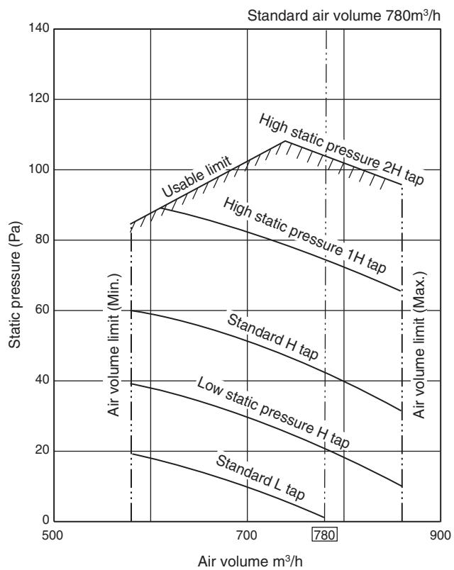
Fig. 1 RAV-SM562BT-E (Round duct)
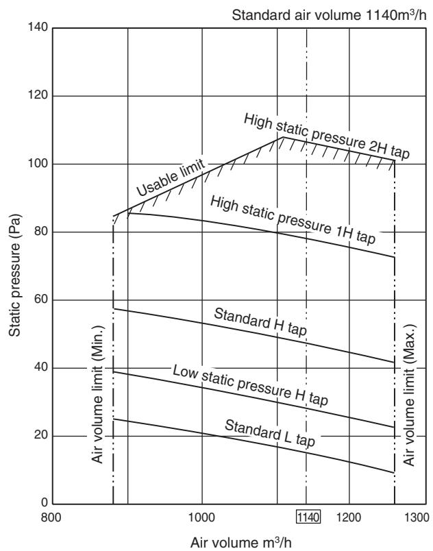
Fig. 3 RAV-SM802BT-E (Round duct)
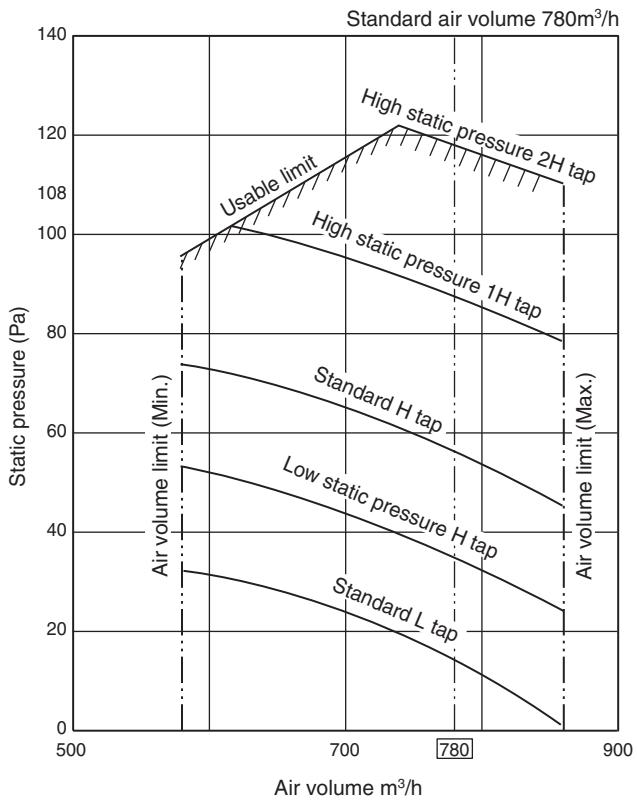
Fig. 2 RAV-SM562BT-E (Square duct)
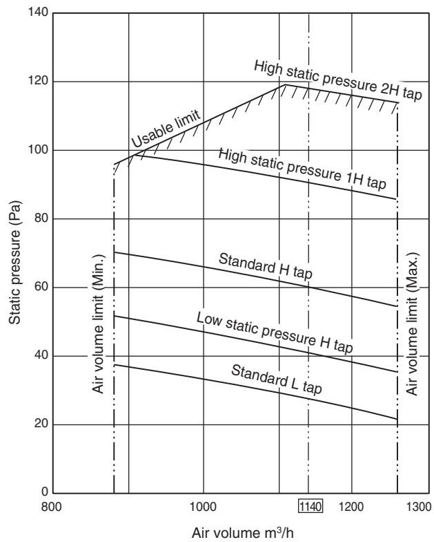
Fig. 4 RAV-SM802BT-E (Square duct)
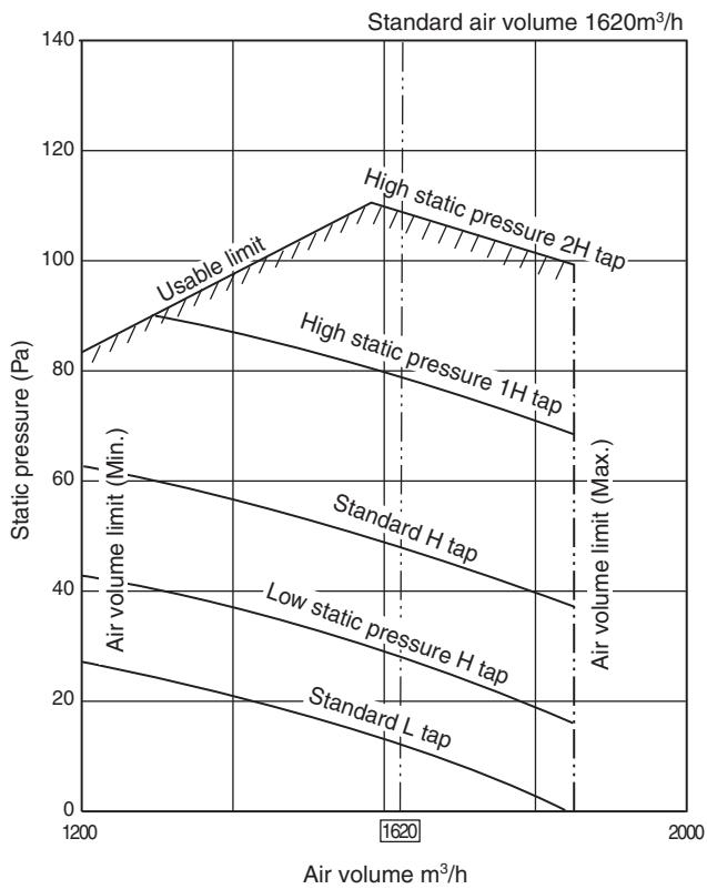
Fig. 5 RAV-SM1102BT-E (Round duct)
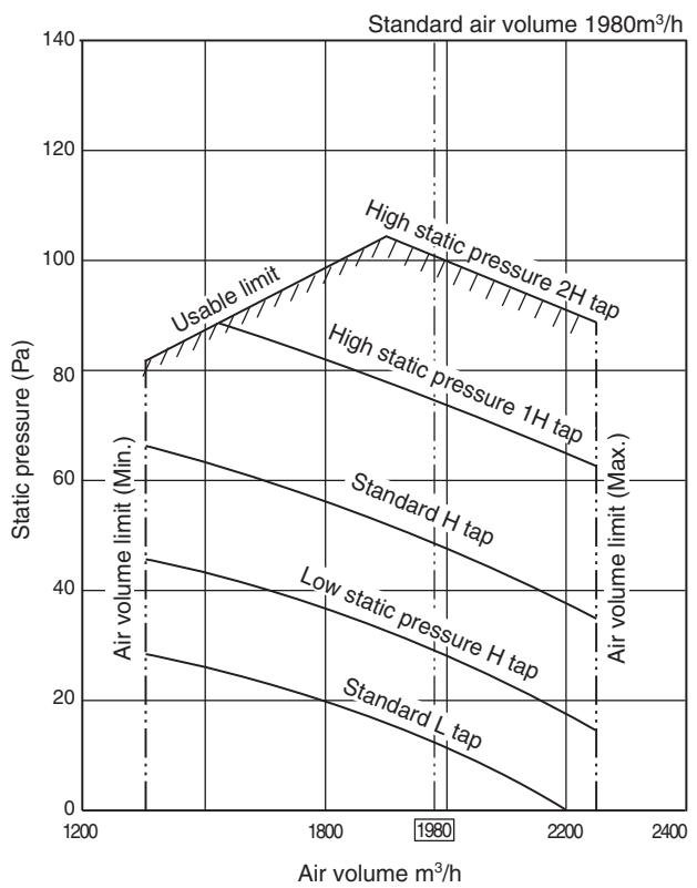
Fig. 7 RAV-SM1402BT-E (Round duct)
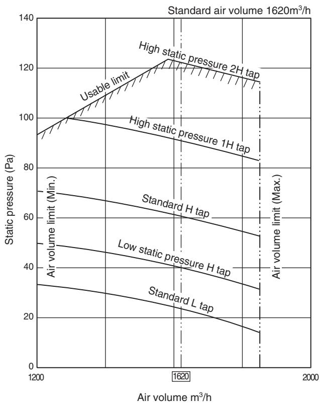
Fig. 6 RAV-SM1102BT-E (Square duct)
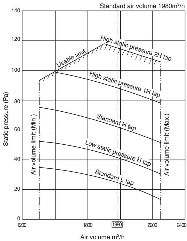
Fig. 8 RAV-SM1402BT-E (Square duct)
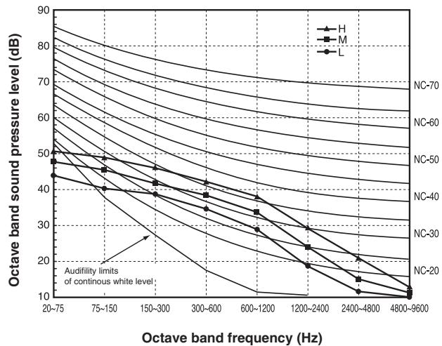
2-2-8. Sound Characteristics
RAV-SM562BT-E
| Fan tap | H | M | L |
| Sound pressure level (dB(A)) | 40 | 37 | 33 |
RAV-SM802BT-E
| Fan tap | H | M | L |
| Sound pressure level (dB(A)) | 40 | 37 | 34 |
RAV-SM1102BT-E
| Fan tap | H | M | L |
| Sound pressure level (dB(A)) | 42 | 39 | 36 |
RAV-SM1402BT-E
| Fan tap | H | M | L |
| Sound pressure level (dB(A)) | 44 | 41 | 38 |
2-3. Ceiling type
2-3-1. Single system Specifications 2-28
2-3-2. Twin system specifications 2-29
2-3-3. Dimension 2-30
2-3-4. Wiring diagram 2-31
2-3-5. Refrigerant cycle diagram 2-32
2-3-6. Sensible capacity table 2-36
2-3-7. Air throw distance chart 2-37
2-3-8. Sound characteristics 2-38
2-3. Ceiling Type
2-3-1. Single System Specifications
| Model | Indoor unit RAV- | SM562CT-E | SM802CT-E | SM1102CT-E | SM1402CT-E |
| Outdoor unit RAV- | SP562AT-E | SP802AT-E | SP1102AT-E | SP1402AT-E |
| Cooling capacity | (kW) | 5.0 | 7.1 | 10.0 | 12.5 |
| Heating capacity | (kW) | 5.6 | 8.0 | 11.2 | 14.0 |
| Power supply | 1 phase 230V (220 - 240V) 50Hz |
| Electrical characteristics | Cooling | Running current (A) | 6.61 - 6.06 | 9.47 - 8.93 | 11.24 - 10.31 | 18.09 - 16.58 |
| Power consumption (kW) | 1.41 | 2.10 | 2.40 | 3.90 |
| Power factor (%) | 97 | 98 | 97 | 98 |
| EER (W/W) | 3.55 | 3.38 | 4.17 | 3.21 |
| Energy efficiency class * | A | A | A | A |
| Energy rating ** | - | - | - | - |
| Heating | Running current (A) | 7.03 - 6.44 | 10.20 - 9.35 | 11.72 - 10.74 | 17.39 - 15.94 |
| Power consumption (kW) | 1.50 | 2.20 | 2.50 | 3.75 |
| Power factor (%) | 97 | 98 | 97 | 98 |
| COP (W/W) | 3.73 | 3.64 | 4.48 | 3.73 |
| Energy efficiency class * | A | A | A | A |
| Energy rating ** | - | - | - | - |
| Appearance | Main unit | Shine white |
| Ceiling panel (Sold separately) | Model | - |
| Panel color | - |
| Outer dimension | Main unit | Height (mm) | 210 | 210 | 210 | 210 |
| Width (mm) | 910 | 1180 | 1595 | 1595 |
| Depth (mm) | 680 | 680 | 680 | 680 |
| Ceiling panel (Sold separately) | Height (mm) | - | - | - | - |
| Width (mm) | - | - | - | - |
| Depth (mm) | - | - | - | - |
| Total weight | Mainunit (kg) | 21 | 25 | 33 | 33 |
| Ceiling panel (Sold separately) (kg) | - | - | - | - |
| Heat exchanger | Finned tube |
| Fan unit | Fan | Centrifugal | Centrifugal | Centrifugal | Centrifugal |
| Standard air flow | H/M/L (m³/min) | 13.0/11.2/10.0 | 18.5/16.7/14.6 | 27.5/24.0/21.2 | 30.0/26.0/23.1 |
| Motor (W) | 30 | 40 | 80 | 80 |
| Air filter | Attached main unit |
| Controller (Sold separately) | RBC-AMT31E2, AS21E2, TCB-SC642TLE2, AX21E2 |
| Connecting pipe | Gas side (mm) | 12.7 | 15.9 | 15.9 | 15.9 |
| Liquid side (mm) | 6.4 | 9.5 | 9.5 | 9.5 |
| Drain port (mm) | VP25 |
| Sound pressure level | H/M/L (dB·A) | 36/33/30 | 38/36/33 | 41/38/35 | 43/40/37 |
| Sound power level | H/M/L (dB·A) | 51/48/45 | 53/51/48 | 56/53/50 | 58/55/52 |
2-3-2. Twin System Specifications
| Model | Type | Under Ceiling |
| Indoor unit 1 RAV- | SM562CT-E | SM802CT-E |
| Indoor unit 2 RAV- | SM562CT-E | SM802CT-E |
| Outdoor unit RAV- | SP1102AT-E | SP1402AT-E |
| Cooling capacity (kW) | 10.0 | 12.3 |
| Heating capacity (kW) | 11.2 | 14.0 |
| Indoor unit |
| Power supply | 1 phase 230V (220 - 240V) 50Hz |
| Electrical characteristics | Cooling | Running current (A) | 11.24-10.31 | 18.09-16.58 |
| Power consumption (kW) | 2.40 | 3.90 |
| Powerfactor (%) | 97 | 98 |
| EER (W/W) | 4.17 | 3.21 |
| Energy efficiency class * | A | A |
| Heating | Running current (A) | 11.95-10.95 | 17.39-15.94 |
| Power consumption (kW) | 2.55 | 3.75 |
| Powerfactor (%) | 97 | 98 |
| COP (W/W) | 4.39 | 3.79 |
| Energy efficiency class * | A | A |
| Fan unit | Fan | Centrifugal | Centrifugal |
| Standard air flow | H/M/L (m³/min) | 13.0/11.2/10.0 | 18.5/16.7/14.6 |
| Motor (W) | 30 | 40 |
| Sound pressure level | H/M/L (dB·A) | 36/33/30 | 38/36/33 |
| Sound power level | H/M/L (dB·A) | 51/48/45 | 53/51/48 |
| Outdoor unit |
| Power supply | 1 phase 230V (220 - 240V) 50Hz (Power exclusive to outdoor is required.) |
| Inter connecting pipes | Standard length (m) | 7.5 | 7.5 |
| Min. length (m) | 5.0 | 5.0 |
| Max. total length (m) | 50 | 50 |
| Over 30m | 40g/m (31m to 50m) |
| Height difference | Outdoor lower (m) | 30 | 30 |
| Outdoor high (m) | 30 | 30 |
| Fan unit | Fan | Propeller fan |
| Standard air flow high (m³/min) | 125 | 125 |
| Motor (W) | 63 + 63 | 63 + 63 |
| Connecting pipe | Gas side | Main (mm) | 15.9 | 15.9 |
| Sub (mm) | 12.7 | 15.9 |
| Liquid side | Main (mm) | 9.5 | 9.5 |
| Sub (mm) | 6.4 | 9.5 |
| Sound pressure level | Cooling/Heating (dB·A) | 49/51 | 53/54 |
| Sound power level | Cooling/Heating (dB·A) | 66/68 | 70/71 |
- : IEC standard, ** : AS standard
2-3-3. Dimension
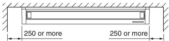
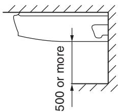
RAV-SM562CT-E, RAV-SM802CT-E, RAV-SM1102CT-E, RAV-SM1402CT-E
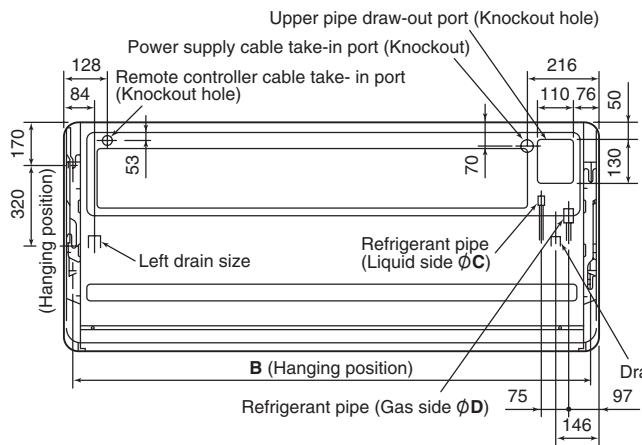
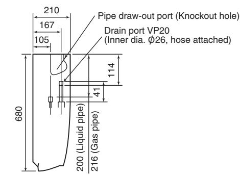
Drain pipe connecting port
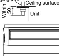
Hanging bolt
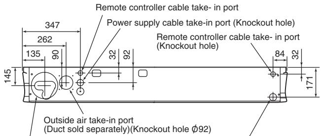
Pipe hole on wall (Φ100 hole)
Drain left pipe draw-out port (Knockout hole)
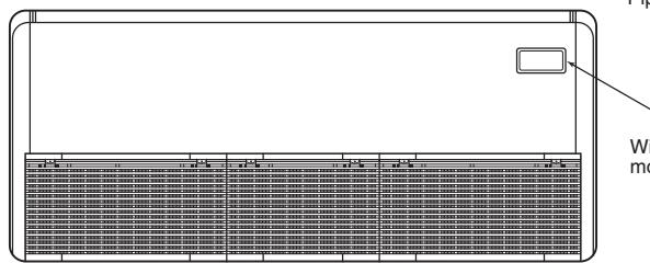
Wireless sensor mounting section
| Model name | A | B | C | D |
| SM562CT | 910 | 855 | ∅6.4 | ∅12.7 |
| SM802CT | 1180 | 1125 | ∅9.5 | ∅15.9 |
| SM1102CT, SM1402CT | 1595 | 1540 |
2-3-4. Wiring Diagram
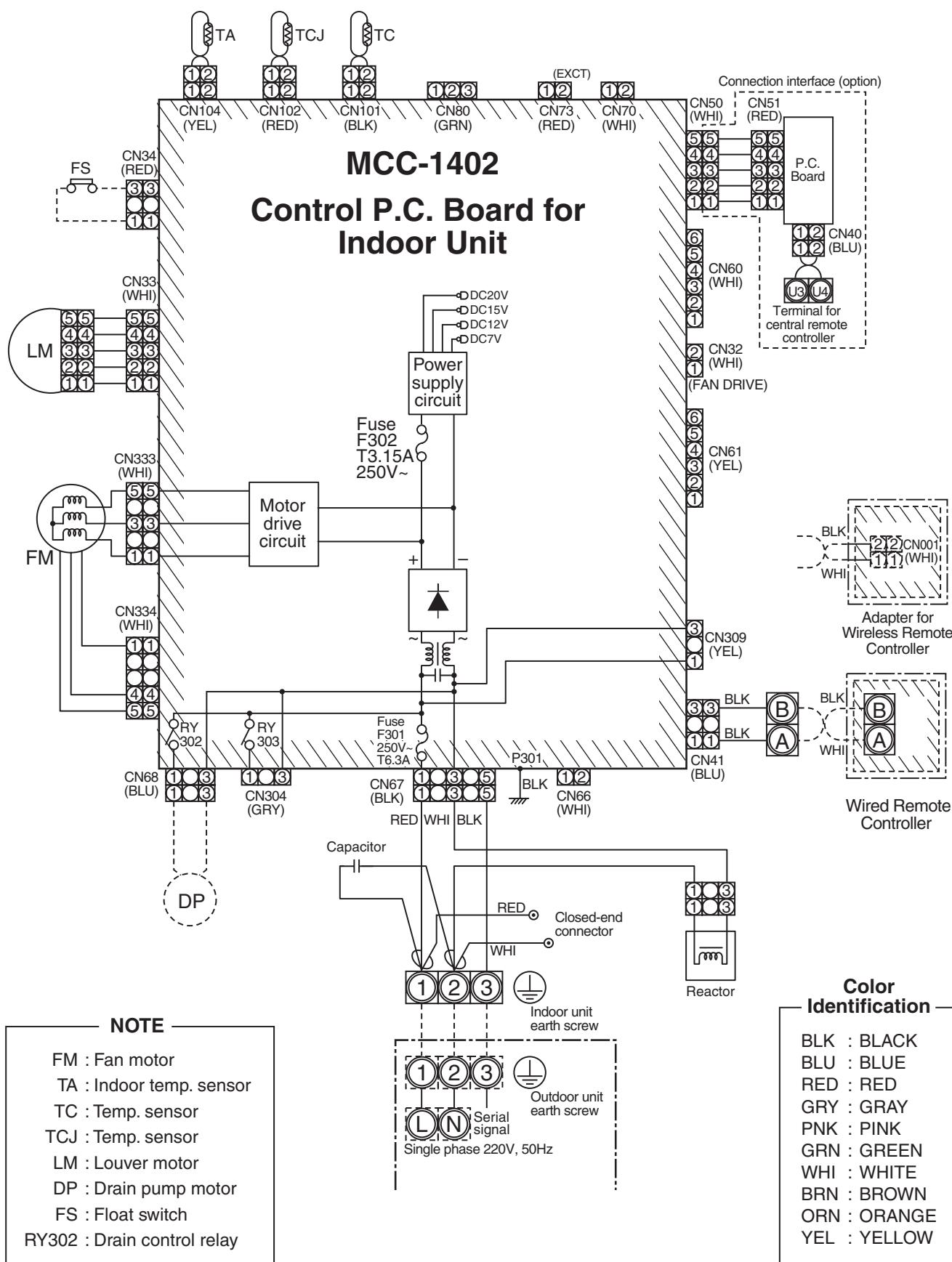
RAV-SM562CT-E, RAV-SM802CT-E, RAV-SM1102CT-E, RAV-SM1402CT-E
2-3-5. Refrigerant Cycle Diagram
RAV-SM562CT-E / RAV-SP562*AT-E
Cooling Heating
| Pressure (MPa) | Pipe surface temperature (°C) | Compressor revolutions per second (rps) * | Indoor fan | Indoor/Outdoor temp. conditions (DB/WB) (°C) |
| Discharge (TD) | Suction (TS) | Indoor heat exchanger (TC) | Outdoor heat exchanger (TE) | Indoor | Outdoor |
| Pd | Ps |
| Cooling | Standard | 2.71 | 1.03 | 75 | 15 | 10 | 38 | 43 | HIGH | 27/19 | 35/- |
| Overload | 3.48 | 1.16 | 81 | 20 | 16 | 51 | 44 | HIGH | 32/24 | 43/- |
| Low load | 1.92 | 0.74 | 34 | 5 | 2 | 11 | 24 | LOW | 18/15.5 | -5/- |
| Heating | Standard | 2.22 | 0.72 | 62 | 6 | 38 | 2 | 41 | HIGH | 20/- | 7/6 |
| Overload | 3.47 | 1.16 | 81 | 20 | 55 | 15 | 41 | LOW | 30/- | 24/18 |
| Low load | 1.79 | 0.25 | 71 | -16 | 30 | -18 | 70 | HIGH | 15/- | -15/(70%) |
- 4 poles are provided to this compressor.
The compressor frequency (Hz) measured with a clamp meter is 2 times of revolutions (rps) of the compressor.
RAV-SM802CT-E / RAV-SP802AT-E
| Pressure (MPa) | Pipe surface temperature (℃) | Compressor revolutions per second (rps) * | Indoor fan | Indoor/Outdoor temp. conditions (DB/WB) (℃) |
| Discharge (TD) | Suction (TS) | Indoor heat exchanger (TC) | Outdoor heat exchanger (TE) | Indoor | Outdoor |
| Pd | Ps |
| Cooling | Standard | 2.72 | 0.93 | 74 | 12 | 11 | 40 | 55 | HIGH | 27/19 | 35/- |
| Overload | 3.57 | 1.10 | 80 | 21 | 17 | 52 | 47 | HIGH | 32/24 | 43/- |
| Low load | 1.89 | 0.74 | 34 | 7 | 2 | 12 | 24 | LOW | 18/15.5 | -5/- |
| Heating | Standard | 2.58 | 0.68 | 72 | 4 | 41 | 2 | 62 | HIGH | 20/- | 7/6 |
| Overload | 3.49 | 1.22 | 79 | 19 | 55 | 16 | 28 | LOW | 30/- | 24/18 |
| Low load | 2.30 | 0.25 | 91 | -17 | 37 | -19 | 90 | HIGH | 15/- | -15/(70%) |
- 4 poles are provided to this compressor.
The compressor frequency (Hz) measured with a clamp meter is 2 times of revolutions (rps) of the compressor.
RAV-SM1102CT-E / RAV-SP1102AT-E
| Pressure (MPa) | Pipe surface temperature (℃) | Compressor revolutions per second (rps) * | Indoor fan | Indoor/Outdoor temp. conditions (DB/WB) (℃) |
| Discharge (TD) | Suction (TS) | Indoor heat exchanger (TC) | Outdoor heat exchanger (TE) | Indoor | Outdoor |
| Pd | Ps |
| Cooling | Standard | 2.55 | 0.98 | 69 | 12 | 10 | 40 | 40 | HIGH | 27/19 | 35/- |
| Overload | 3.28 | 1.08 | 82 | 17 | 16 | 48 | 50 | HIGH | 32/24 | 43/- |
| Low load | 1.76 | 0.76 | 47 | 8 | 5 | 27 | 24 | LOW | 18/15.5 | -5/- |
| Heating | Standard | 2.58 | 0.73 | 68 | 3 | 40 | 3 | 44 | HIGH | 20/- | 7/6 |
| Overload | 3.43 | 1.18 | 75 | 20 | 56 | 16 | 24 | LOW | 30/- | 24/18 |
| Low load | 2.10 | 0.32 | 88 | -14 | 34 | -13 | 63 | HIGH | 15/- | -15/(70%) |
- 4 poles are provided to this compressor.
The compressor frequency (Hz) measured with a clamp meter is 2 times of revolutions (rps) of the compressor.
RAV-SM1402CT-E / RAV-SP1402AT-E
| Pressure (MPa) | Pipe surface temperature (℃) | Compressor revolutions per second (rps) * | Indoor fan | Indoor/Outdoor temp. conditions (DB/WB) (℃) |
| Discharge (TD) | Suction (TS) | Indoor heat exchanger (TC) | Outdoor heat exchanger (TE) | Indoor | Outdoor |
| Pd | Ps |
| Cooling | Standard | 2.76 | 0.91 | 74 | 11 | 9 | 39 | 53 | HIGH | 27/19 | 35/- |
| Overload | 3.46 | 1.03 | 82 | 17 | 16 | 48 | 51 | HIGH | 32/24 | 43/- |
| Low load | 1.77 | 0.78 | 48 | 9 | 6 | 27 | 24 | LOW | 18/15.5 | -5/- |
| Heating | Standard | 2.65 | 0.69 | 75 | 3 | 43 | 3 | 55 | HIGH | 20/- | 7/6 |
| Overload | 3.33 | 1.08 | 74 | 19 | 55 | 15 | 24 | LOW | 30/- | 24/18 |
| Low load | 2.50 | 0.22 | 98 | -22 | 43 | -18 | 73 | HIGH | 15/- | -15/(70%) |
- 4 poles are provided to this compressor.
The compressor frequency (Hz) measured with a clamp meter is 2 times of revolutions (rps) of the compressor.
2-3-6. Sensible Capacity Table
RAV-SM562CT-E, SM802CT-E, SM1102CT-E, SM1402CT-E
| indoor air temp. |
| unit size | outdoor air temp. CDB | 14.0CWB 20.0CDB | 16.0CWB 23.0CDB | 18.0CWB 26.0CDB | 19.0CWB 27.0CDB | 20.0CWB 28.0CDB | 22.0CWB 30.0CDB | 24.0CWB 32.0CDB |
| TC | SHC | TC | SHC | TC | SHC | TC | SHC | TC | SHC | TC | SHC | TC | SHC |
| 562 | 10.0 | 4.7 | 3.3 | 5.2 | 3.6 | 5.6 | 3.9 | 5.7 | 4.0 | 5.9 | 4.1 | 6.2 | 4.4 | 6.5 | 4.6 |
| 12.0 | 4.7 | 3.3 | 5.2 | 3.6 | 5.5 | 3.9 | 5.7 | 4.0 | 5.8 | 4.1 | 6.2 | 4.3 | 6.5 | 4.5 |
| 14.0 | 4.6 | 3.2 | 5.1 | 3.6 | 5.5 | 3.8 | 5.6 | 4.0 | 5.8 | 4.1 | 6.1 | 4.3 | 6.4 | 4.5 |
| 16.0 | 4.6 | 3.2 | 5.1 | 3.6 | 5.4 | 3.8 | 5.6 | 3.9 | 5.8 | 4.0 | 6.1 | 4.3 | 6.4 | 4.5 |
| 18.0 | 4.6 | 3.2 | 5.0 | 3.5 | 5.4 | 3.8 | 5.6 | 3.9 | 5.7 | 4.0 | 6.1 | 4.2 | 6.3 | 4.4 |
| 20.0 | 4.5 | 3.2 | 5.0 | 3.5 | 5.4 | 3.8 | 5.5 | 3.9 | 5.7 | 4.0 | 6.0 | 4.2 | 6.3 | 4.4 |
| 21.0 | 4.5 | 3.2 | 5.0 | 3.5 | 5.3 | 3.7 | 5.5 | 3.8 | 5.6 | 4.0 | 6.0 | 4.2 | 6.3 | 4.4 |
| 23.0 | 4.5 | 3.1 | 4.9 | 3.5 | 5.3 | 3.7 | 5.4 | 3.8 | 5.6 | 3.9 | 5.9 | 4.1 | 6.2 | 4.3 |
| 25.0 | 4.4 | 3.1 | 4.9 | 3.4 | 5.2 | 3.7 | 5.4 | 3.8 | 5.5 | 3.9 | 5.9 | 4.1 | 6.1 | 4.3 |
| 27.0 | 4.4 | 3.1 | 4.8 | 3.4 | 5.2 | 3.6 | 5.3 | 3.7 | 5.5 | 3.8 | 5.8 | 4.0 | 6.0 | 4.2 |
| 29.0 | 4.3 | 3.0 | 4.8 | 3.3 | 5.1 | 3.6 | 5.2 | 3.7 | 5.4 | 3.8 | 5.7 | 4.0 | 6.0 | 4.2 |
| 31.0 | 4.2 | 3.0 | 4.7 | 3.3 | 5.0 | 3.5 | 5.2 | 3.6 | 5.3 | 3.7 | 5.6 | 3.9 | 5.9 | 4.1 |
| 33.0 | 4.2 | 2.9 | 4.6 | 3.2 | 4.9 | 3.5 | 5.1 | 3.6 | 5.2 | 3.7 | 5.5 | 3.9 | 5.8 | 4.1 |
| 35.0 | 4.1 | 2.9 | 4.5 | 3.2 | 4.9 | 3.4 | 5.0 | 3.5 | 5.1 | 3.6 | 5.4 | 3.8 | 5.7 | 4.0 |
| 37.0 | 4.0 | 2.8 | 4.4 | 3.1 | 4.8 | 3.3 | 4.9 | 3.4 | 5.0 | 3.5 | 5.3 | 3.7 | 5.6 | 3.9 |
| 39.0 | 3.9 | 2.8 | 4.4 | 3.1 | 4.7 | 3.3 | 4.8 | 3.4 | 4.9 | 3.5 | 5.2 | 3.7 | 5.5 | 3.8 |
| 802 | 10.0 | 6.7 | 4.7 | 7.4 | 5.2 | 7.9 | 5.6 | 8.1 | 5.7 | 8.3 | 5.9 | 8.8 | 6.2 | 9.2 | 6.5 |
| 12.0 | 6.6 | 4.7 | 7.3 | 5.2 | 7.8 | 5.5 | 8.1 | 5.7 | 8.3 | 5.8 | 8.8 | 6.2 | 9.2 | 6.5 |
| 14.0 | 6.6 | 4.6 | 7.3 | 5.1 | 7.8 | 5.5 | 8.0 | 5.6 | 8.2 | 5.8 | 8.7 | 6.1 | 9.1 | 6.4 |
| 16.0 | 6.5 | 4.6 | 7.2 | 5.1 | 7.7 | 5.4 | 8.0 | 5.6 | 8.2 | 5.8 | 8.7 | 6.1 | 9.1 | 6.4 |
| 18.0 | 6.5 | 4.6 | 7.2 | 5.0 | 7.7 | 5.4 | 7.9 | 5.6 | 8.1 | 5.7 | 8.6 | 6.1 | 9.0 | 6.3 |
| 20.0 | 6.4 | 4.5 | 7.1 | 5.0 | 7.6 | 5.4 | 7.8 | 5.5 | 8.1 | 5.7 | 8.5 | 6.0 | 8.9 | 6.3 |
| 21.0 | 6.4 | 4.5 | 7.1 | 5.0 | 7.6 | 5.3 | 7.8 | 5.5 | 8.0 | 5.6 | 8.5 | 6.0 | 8.9 | 6.3 |
| 23.0 | 6.3 | 4.5 | 7.0 | 4.9 | 7.5 | 5.3 | 7.7 | 5.4 | 7.9 | 5.6 | 8.4 | 5.9 | 8.8 | 6.2 |
| 25.0 | 6.3 | 4.4 | 6.9 | 4.9 | 7.4 | 5.2 | 7.6 | 5.4 | 7.9 | 5.5 | 8.3 | 5.9 | 8.7 | 6.1 |
| 27.0 | 6.2 | 4.4 | 6.8 | 4.8 | 7.3 | 5.2 | 7.5 | 5.3 | 7.8 | 5.5 | 8.2 | 5.8 | 8.6 | 6.0 |
| 29.0 | 6.1 | 4.3 | 6.7 | 4.8 | 7.2 | 5.1 | 7.4 | 5.2 | 7.7 | 5.4 | 8.1 | 5.7 | 8.5 | 6.0 |
| 31.0 | 6.0 | 4.2 | 6.7 | 4.7 | 7.1 | 5.0 | 7.3 | 5.2 | 7.5 | 5.3 | 8.0 | 5.6 | 8.4 | 5.9 |
| 33.0 | 5.9 | 4.2 | 6.5 | 4.6 | 7.0 | 4.9 | 7.2 | 5.1 | 7.4 | 5.2 | 7.9 | 5.5 | 8.2 | 5.8 |
| 35.0 | 5.8 | 4.1 | 6.4 | 4.5 | 6.9 | 4.9 | 7.1 | 5.0 | 7.3 | 5.1 | 7.7 | 5.4 | 8.1 | 5.7 |
| 37.0 | 5.7 | 4.0 | 6.3 | 4.4 | 6.8 | 4.8 | 7.0 | 4.9 | 7.2 | 5.0 | 7.6 | 5.3 | 7.9 | 5.6 |
| 39.0 | 5.6 | 3.9 | 6.2 | 4.4 | 6.6 | 4.7 | 6.8 | 4.8 | 7.0 | 4.9 | 7.4 | 5.2 | 7.8 | 5.5 |
| 1102 | 10.0 | 9.4 | 6.8 | 10.4 | 7.2 | 11.1 | 7.7 | 11.4 | 7.7 | 11.8 | 7.6 | 12.5 | 7.6 | 13.0 | 7.4 |
| 12.0 | 9.3 | 6.7 | 10.3 | 7.2 | 11.0 | 7.6 | 11.4 | 7.6 | 11.7 | 7.6 | 12.4 | 7.5 | 12.9 | 7.4 |
| 14.0 | 9.3 | 6.7 | 10.2 | 7.1 | 11.0 | 7.6 | 11.3 | 7.6 | 11.6 | 7.6 | 12.3 | 7.5 | 12.9 | 7.3 |
| 16.0 | 9.2 | 6.7 | 10.2 | 7.1 | 10.9 | 7.5 | 11.2 | 7.5 | 11.5 | 7.5 | 12.2 | 7.4 | 12.8 | 7.3 |
| 18.0 | 9.1 | 6.6 | 10.1 | 7.0 | 10.8 | 7.5 | 11.1 | 7.5 | 11.4 | 7.4 | 12.1 | 7.4 | 12.7 | 7.2 |
| 20.0 | 9.1 | 6.5 | 10.0 | 7.0 | 10.7 | 7.4 | 11.0 | 7.4 | 11.3 | 7.4 | 12.0 | 7.3 | 12.6 | 7.1 |
| 21.0 | 9.0 | 6.5 | 10.0 | 6.9 | 10.7 | 7.4 | 11.0 | 7.4 | 11.3 | 7.3 | 12.0 | 7.3 | 12.5 | 7.1 |
| 23.0 | 8.9 | 6.4 | 9.9 | 6.9 | 10.6 | 7.3 | 10.9 | 7.3 | 11.2 | 7.3 | 11.8 | 7.2 | 12.4 | 7.0 |
| 25.0 | 8.8 | 6.4 | 9.8 | 6.8 | 10.4 | 7.2 | 10.8 | 7.2 | 11.1 | 7.2 | 11.7 | 7.1 | 12.2 | 7.0 |
| 27.0 | 8.7 | 6.3 | 9.6 | 6.7 | 10.3 | 7.1 | 10.6 | 7.1 | 10.9 | 7.1 | 11.6 | 7.0 | 12.1 | 6.9 |
| 29.0 | 8.6 | 6.2 | 9.5 | 6.6 | 10.2 | 7.0 | 10.5 | 7.0 | 10.8 | 7.0 | 11.4 | 6.9 | 11.9 | 6.8 |
| 31.0 | 8.5 | 6.1 | 9.4 | 6.5 | 10.0 | 6.9 | 10.3 | 6.9 | 10.6 | 6.9 | 11.3 | 6.8 | 11.8 | 6.7 |
| 33.0 | 8.4 | 6.0 | 9.2 | 6.4 | 9.9 | 6.8 | 10.2 | 6.8 | 10.5 | 6.8 | 11.1 | 6.7 | 11.6 | 6.6 |
| 35.0 | 8.2 | 5.9 | 9.1 | 6.3 | 9.7 | 6.7 | 10.0 | 6.7 | 10.3 | 6.7 | 10.9 | 6.6 | 11.4 | 6.5 |
| 37.0 | 8.1 | 5.8 | 8.9 | 6.2 | 9.5 | 6.6 | 9.8 | 6.6 | 10.1 | 6.6 | 10.7 | 6.5 | 11.2 | 6.4 |
| 39.0 | 7.9 | 5.7 | 8.7 | 6.1 | 9.3 | 6.5 | 9.6 | 6.4 | 9.9 | 6.4 | 10.5 | 6.4 | 10.9 | 6.2 |
| 1402 | 10.0 | 11.5 | 8.1 | 12.8 | 8.6 | 13.7 | 9.2 | 14.1 | 9.1 | 14.5 | 9.1 | 15.3 | 9.0 | 16.0 | 8.8 |
| 12.0 | 11.5 | 8.0 | 12.7 | 8.6 | 13.6 | 9.1 | 14.0 | 9.1 | 14.4 | 9.1 | 15.2 | 9.0 | 15.9 | 8.8 |
| 14.0 | 11.4 | 8.0 | 12.6 | 8.5 | 13.5 | 9.1 | 13.9 | 9.0 | 14.3 | 9.0 | 15.1 | 8.9 | 15.8 | 8.7 |
| 16.0 | 11.3 | 7.9 | 12.5 | 8.5 | 13.4 | 9.0 | 13.8 | 9.0 | 14.2 | 9.0 | 15.0 | 8.9 | 15.7 | 8.7 |
| 18.0 | 11.2 | 7.9 | 12.4 | 8.4 | 13.3 | 8.9 | 13.7 | 8.9 | 14.1 | 8.9 | 14.9 | 8.8 | 15.6 | 8.6 |
| 20.0 | 11.1 | 7.8 | 12.3 | 8.3 | 13.2 | 8.8 | 13.6 | 8.8 | 14.0 | 8.8 | 14.8 | 8.7 | 15.5 | 8.5 |
| 21.0 | 11.1 | 7.8 | 12.3 | 8.3 | 13.1 | 8.8 | 13.5 | 8.8 | 13.9 | 8.8 | 14.7 | 8.7 | 15.4 | 8.5 |
| 23.0 | 11.0 | 7.7 | 12.1 | 8.2 | 13.0 | 8.7 | 13.4 | 8.7 | 13.8 | 8.7 | 14.6 | 8.6 | 15.2 | 8.4 |
| 25.0 | 10.9 | 7.6 | 12.0 | 8.1 | 12.8 | 8.6 | 13.2 | 8.6 | 13.6 | 8.6 | 14.4 | 8.5 | 15.1 | 8.3 |
| 27.0 | 10.7 | 7.5 | 11.8 | 8.0 | 12.7 | 8.5 | 13.1 | 8.5 | 13.4 | 8.5 | 14.2 | 8.4 | 14.9 | 8.2 |
| 29.0 | 10.6 | 7.4 | 11.7 | 7.9 | 12.5 | 8.4 | 12.9 | 8.4 | 13.3 | 8.4 | 14.0 | 8.3 | 14.7 | 8.1 |
| 31.0 | 10.4 | 7.3 | 11.5 | 7.8 | 12.3 | 8.3 | 12.7 | 8.3 | 13.1 | 8.3 | 13.8 | 8.2 | 14.5 | 8.0 |
| 33.0 | 10.3 | 7.2 | 11.3 | 7.7 | 12.2 | 8.2 | 12.5 | 8.1 | 12.9 | 8.1 | 13.6 | 8.0 | 14.3 | 7.9 |
| 35.0 | 10.1 | 7.1 | 11.2 | 7.5 | 11.9 | 8.0 | 12.3 | 8.0 | 12.7 | 8.0 | 13.4 | 7.9 | 14.0 | 7.7 |
| 37.0 | 9.9 | 6.9 | 10.9 | 7.4 | 11.7 | 7.9 | 12.1 | 7.8 | 12.4 | 7.8 | 13.1 | 7.8 | 13.7 | 7.6 |
| 39.0 | 9.7 | 6.8 | 10.7 | 7.3 | 11.5 | 7.7 | 11.8 | 7.7 | 12.2 | 7.7 | 12.9 | 7.6 | 13.5 | 7.4 |
TC:Total Capacity [kW]
SHC:Sensible Heat Capacity [kW]
2-3-7. Air Throw Distance Chart
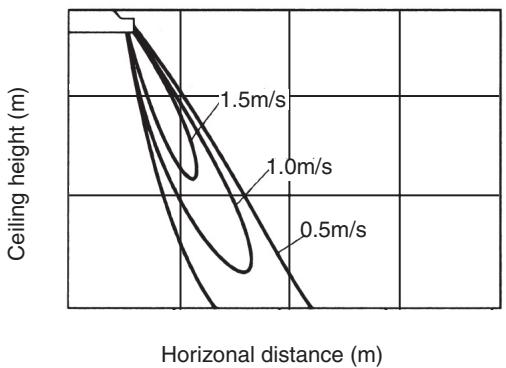
RAV-SM562CT-E
| Fan tap | H | M | L |
| Sound pressure level (dB(A)) | 36 | 33 | 30 |
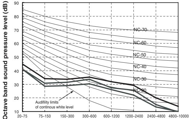
Octave band frequency (Hz)
RAV-SM802CT-E
| Fan tap | H | M | L |
| Sound pressure level (dB(A)) | 38 | 36 | 33 |
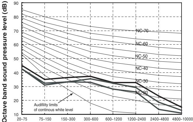
Octave band frequency (Hz)
RAV-SM1102CT-E
| Fan tap | H | M | L |
| Sound pressure level (dB(A)) | 41 | 38 | 35 |
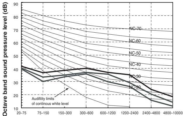
Octave band frequency (Hz)
RAV-SM1402CT-E
| Fan tap | H | M | L |
| Sound pressure level (dB(A)) | 43 | 40 | 37 |
Octave band frequency (Hz)
2-4. High wall type
2-4-1. Single system Specifications 2-40
2-4-2. Twin system specifications 2-41
2-4-3. Dimension 2-42
2-4-4. Wiring diagram 2-43
2-4-5. Refrigerant cycle diagram 2-44
2-4-6. Sensible capacity table 2-46
2-4-7. Air throw distance chart 2-47
2-4-8. Sound characteristics 2-48
2-4. High Wall Type
2-4-1. Single Sprit System
| Model | Indoor unit | RAV-SM562KRT-E | RAV-SM802KRT-E |
| Outdoor unit | RAV-SP562AT-E | RAV-SP801AT-E |
| Cooling capacity (kW) | 5.0 | 6.9 |
| Heating capacity (kW) | 5.6 | 8.0 |
| Power supply | 1 phase 230V (220-240V) 50Hz |
| Electrical characteristics | Cooling | Running current (A) | 8.33-7.63 | 13.15-12.05 |
| Power consumption (kW) | 1.39 | 2.40 |
| Power factor (%) | 95 | 94 |
| EER (W/W) | 3.60 | 2.88 |
| Energy efficiency class* | A | C |
| Energy rating** | - | - |
| Heating | Running current (A) | 8.138-7.46 | 12.91-11.84 |
| Power consumption (kW) | 1.55 | 2.40 |
| Power factor (%) | 95 | 94 |
| COP (W/W) | 3.61 | 3.33 |
| Energy efficiency class* | A | C |
| Energy rating** | - | - |
| Appearance | Main unit | Pure white |
| Ceiling panel (Sold separately) | Model | - |
| Panel color | - |
| Outer dimension | Main unit | Height (mm) | 298 | 298 |
| Width (mm) | 998 | 998 |
| Depth (mm) | 208 | 208 |
| Ceiling panel (Sold separately) | Height (mm) | - | - |
| Width (mm) | - | - |
| Depth (mm) | - | - |
| Total weight | Main unit (kg) | 12 | 12 |
| Ceiling panel (Sold separately) (kg) | - | - |
| Heat exchanger | Finned tube |
| Fan unit | Fan | Turbo fan | Turbo fan |
| Standard air flow | H/M/L (m³/min) | 14.0/12.5/10.7 | 18.5/14.6/12.2 |
| Motor (W) | 30 | 30 |
| Air filter | Attached main unit |
| Controller | FCU attached with WH-H07EE |
| Connecting pipe | Gas side (mm) | 12.7 | 15.9 |
| Liquid side (mm) | 6.4 | 9.5 |
| Drain port (mm) | VP16 |
| Sound pressure level | H/M/L (dB·A) | 39/36/33 | 45/41/36 |
| Sound power level | H/M/L (dB·A) | 54/51/48 | 60/56/51 |
: IEC standard, *: AS standard
2-4-2. Twin System Specifications
| Model | Type | High wall Type |
| Indoor unit 1 | RAV-SM562KRT-E | RAV-SM802KRT-E |
| Indoor unit 2 | RAV-SM562KRT-E | RAV-SM802KRT-E |
| Outdoor unit | RAV-SP1102AT-E | RAV-SP1402AT-E |
| Cooling capacity (kW) | 10.0 | 12.3 |
| Heating capacity (kW) | 11.2 | 14.0 |
| Indoor unit |
| Power supply | 1 phase 230V (220-240V) 50Hz |
| Electrical characteristics | Cooling | Running current (A) | - | - |
| Power consumption (kW) | 2.40 | 4.00 |
| Power factor (%) | - | - |
| EER (W/W) | 4.17 | 3.08 |
| Energy efficiency class* | A | A |
| Heating | Running current (A) | - | - |
| Power consumption (kW) | 2.55 | 3.85 |
| Power factor (%) | - | - |
| COP (W/W) | 4.39 | 3.64 |
| Energy efficiency class* | A | A |
| Fan unit | Fan | Cross flow fan | Cross flow fan |
| Standard air flow | H/M/L (m³/min) | 14.0/12.5/10.7 | 18.5/14.6/12.2 |
| Motor (W) | 30 | 30 |
| Sound pressure level | H/M/L (dB·A) | 39/36/33 | 45/41/36 |
| Sound power level | H/M/L (dB·A) | 54/51/48 | 60/56/51 |
| Outdoor unit |
| Power supply | phase 230V (220-240V) 50Hz (Power exclusive to outdoor is requirec) |
| Pipe | Standard length (m) | 7.5 | 7.5 |
| Max. total length (m) | 50 | 50 |
| Over 30m | 40g/m (31m to 50m) | 40g/m (31m to 50m) |
| Height difference | Outdoor lower (m) | 30 | 30 |
| Outdoor high (m) | 30 | 30 |
| Fan unit | Fan | Propeller fan |
| Standard air flow High (m³/min) | 125 | 125 |
| Motor (W) | 63 + 63 | 63 + 63 |
| Connecting pipe | Gas side | Main (mm) | 15.9 | 15.9 |
| Sub (mm) | 12.7 | 15.9 |
| Liquid side | Main (mm) | 9.5 | 9.5 |
| Sub (mm) | 6.4 | 9.5 |
| Sound pressure level | Cooling/Heatir (dB·A) | 49/51 | 53/54 |
| Sound power level | Cooling/Heatir (dB·A) | 66/68 | 70/71 |
*: IEC standard
2-4-3. Dimension
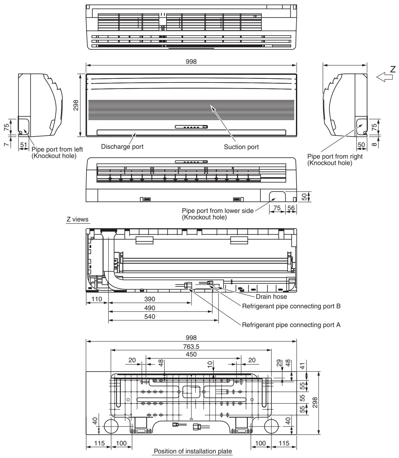
RAV-SM562KRT-E/RAV-SM802KRT-E
| Liquid Side | B Gas Side |
| SM561 | ∅6.4 | ∅12.7 |
| SM801 | ∅9.5 | ∅15.9 |
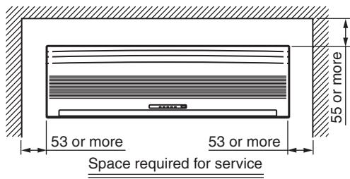
2-4-4. Wiring Diagram
Notes)
1. Material: White slick paper 75kg (with adhesive on the reverse side)
2. Ground color: White
3. Printing color: Black
4. Before the production, submit three copies of photographic printing paper draft
and it should be approved by the designer
2-4-5. Refrigerant Cycle Diagram
RAV-SP562AT-E, RAV-SM562KRT-E
| Pressure (MPa) | Pipe surface temperature (℃) | Compressor revolutions per second (rps) * | Indoor fan | Indoor/Outdoor temp. conditions (DB/WB) (℃) |
| Discharge (TD) | Suction (TS) | Indoor heat exchanger (TC) | Outdoor heat exchanger (TE) | Indoor | Outdoor |
| Pd | Ps |
| Cooling | Standard | 2.71 | 1.03 | 75 | 15 | 10 | 38 | 43 | HIGH | 27/19 | 35/- |
| Overload | 3.48 | 1.16 | 81 | 20 | 16 | 51 | 44 | HIGH | 32/24 | 43/- |
| Low load | 1.92 | 0.74 | 34 | 5 | 2 | 11 | 24 | LOW | 18/15.5 | -5/- |
| Heating | Standard | 2.22 | 0.72 | 62 | 6 | 38 | 2 | 41 | HIGH | 20/- | 7/6 |
| Overload | 3.47 | 1.16 | 81 | 20 | 55 | 15 | 41 | LOW | 30/- | 24/18 |
| Low load | 1.79 | 0.25 | 71 | -16 | 30 | -18 | 70 | HIGH | 15/- | -15/(70%) |
- 4 poles are provided to this compressor.
The compressor frequency (Hz) measured with a clamp meter is 2 times of revolutions (rps) of the compressor.
RAV-SP802AT-E, RAV-SM802KRT-E

| Pressure (MPa) | Pipe surface temperature (°C) | Compressor revolutions per second (rps) * | Indoor fan | Indoor/Outdoor temp. conditions (DB/WB) (°C) |
| Discharge (TD) | Suction (TS) | Indoor heat exchanger (TC) | Outdoor heat exchanger (TE) | Indoor | Outdoor |
| Pd | Ps |
| Cooling | Standard | 2.72 | 0.93 | 74 | 12 | 11 | 40 | 55 | HIGH | 27/19 | 35/- |
| Overload | 3.57 | 1.10 | 80 | 21 | 17 | 52 | 47 | HIGH | 32/24 | 43/- |
| Low load | 1.89 | 0.74 | 34 | 7 | 2 | 12 | 24 | LOW | 18/15.5 | -5/- |
| Heating | Standard | 2.58 | 0.68 | 72 | 4 | 41 | 2 | 62 | HIGH | 20/- | 7/6 |
| Overload | 3.49 | 1.22 | 79 | 19 | 55 | 16 | 28 | LOW | 30/- | 24/18 |
| Low load | 2.30 | 0.25 | 91 | -17 | 37 | -19 | 90 | HIGH | 15/- | -15/(70%) |
- 4 poles are provided to this compressor.
The compressor frequency (Hz) measured with a clamp meter is 2 times of revolutions (rps) of the compressor.
2-4-6. Sensibles Capacity Table
RAV-SM562KRT-E, SM802KRT-E
| indoor air temp. |
| unit size | outdoor air temp. CDB | 14.0CWB 20.0CDB | 16.0CWB 23.0CDB | 18.0CWB 26.0CDB | 19.0CWB 27.0CDB | 20.0CWB 28.0CDB | 22.0CWB 30.0CDB | 24.0CWB 32.0CDB |
| TC | SHC | TC | SHC | TC | SHC | TC | SHC | TC | SHC | TC | SHC | TC | SHC |
| 562 | 10.0 | 4.8 | 4.0 | 5.3 | 4.3 | 5.7 | 4.6 | 5.8 | 4.6 | 6.0 | 4.6 | 6.3 | 4.5 | 6.6 | 4.4 |
| 12.0 | 4.8 | 4.0 | 5.3 | 4.3 | 5.6 | 4.6 | 5.8 | 4.5 | 6.0 | 4.5 | 6.3 | 4.5 | 6.6 | 4.4 |
| 14.0 | 4.7 | 4.0 | 5.2 | 4.3 | 5.6 | 4.5 | 5.8 | 4.5 | 5.9 | 4.5 | 6.3 | 4.5 | 6.6 | 4.4 |
| 16.0 | 4.7 | 4.0 | 5.2 | 4.2 | 5.6 | 4.5 | 5.7 | 4.5 | 5.9 | 4.5 | 6.2 | 4.4 | 6.5 | 4.3 |
| 18.0 | 4.7 | 3.9 | 5.1 | 4.2 | 5.5 | 4.5 | 5.7 | 4.4 | 5.8 | 4.4 | 6.2 | 4.4 | 6.5 | 4.3 |
| 20.0 | 4.6 | 3.9 | 5.1 | 4.2 | 5.5 | 4.4 | 5.6 | 4.4 | 5.8 | 4.4 | 6.1 | 4.4 | 6.4 | 4.3 |
| 21.0 | 4.6 | 3.9 | 5.1 | 4.1 | 5.4 | 4.4 | 5.6 | 4.4 | 5.8 | 4.4 | 6.1 | 4.3 | 6.4 | 4.2 |
| 23.0 | 4.6 | 3.8 | 5.0 | 4.1 | 5.4 | 4.4 | 5.5 | 4.3 | 5.7 | 4.3 | 6.0 | 4.3 | 6.3 | 4.2 |
| 25.0 | 4.5 | 3.8 | 5.0 | 4.1 | 5.3 | 4.3 | 5.5 | 4.3 | 5.6 | 4.3 | 6.0 | 4.2 | 6.2 | 4.2 |
| 27.0 | 4.4 | 3.8 | 4.9 | 4.0 | 5.3 | 4.3 | 5.4 | 4.2 | 5.6 | 4.2 | 5.9 | 4.2 | 6.2 | 4.1 |
| 29.0 | 4.4 | 3.7 | 4.8 | 4.0 | 5.2 | 4.2 | 5.3 | 4.2 | 5.5 | 4.2 | 5.8 | 4.1 | 6.1 | 4.1 |
| 31.0 | 4.3 | 3.7 | 4.8 | 3.9 | 5.1 | 4.1 | 5.3 | 4.1 | 5.4 | 4.1 | 5.7 | 4.1 | 6.0 | 4.0 |
| 33.0 | 4.3 | 3.6 | 4.7 | 3.8 | 5.0 | 4.1 | 5.2 | 4.1 | 5.3 | 4.1 | 5.6 | 4.0 | 5.9 | 3.9 |
| 35.0 | 4.2 | 3.5 | 4.6 | 3.8 | 5.0 | 4.0 | 5.1 | 4.0 | 5.2 | 4.0 | 5.6 | 4.0 | 5.8 | 3.9 |
| 37.0 | 4.1 | 3.5 | 4.5 | 3.7 | 4.9 | 3.9 | 5.0 | 3.9 | 5.1 | 3.9 | 5.4 | 3.9 | 5.7 | 3.8 |
| 39.0 | 4.0 | 3.4 | 4.4 | 3.6 | 4.8 | 3.9 | 4.9 | 3.8 | 5.0 | 3.8 | 5.3 | 3.8 | 5.6 | 3.7 |
| 802 | 10.0 | 6.3 | 5.2 | 6.9 | 5.5 | 7.4 | 5.8 | 7.7 | 5.8 | 7.9 | 5.8 | 8.3 | 5.8 | 8.7 | 5.6 |
| 12.0 | 6.3 | 5.1 | 6.9 | 5.5 | 7.4 | 5.8 | 7.6 | 5.8 | 7.8 | 5.8 | 8.3 | 5.7 | 8.7 | 5.6 |
| 14.0 | 6.2 | 5.1 | 6.9 | 5.4 | 7.3 | 5.8 | 7.6 | 5.8 | 7.8 | 5.8 | 8.2 | 5.7 | 8.6 | 5.6 |
| 16.0 | 6.2 | 5.1 | 6.8 | 5.4 | 7.3 | 5.7 | 7.5 | 5.7 | 7.7 | 5.7 | 8.2 | 5.6 | 8.6 | 5.5 |
| 18.0 | 6.1 | 5.0 | 6.8 | 5.3 | 7.2 | 5.7 | 7.5 | 5.7 | 7.7 | 5.7 | 8.1 | 5.6 | 8.5 | 5.5 |
| 20.0 | 6.1 | 5.0 | 6.7 | 5.3 | 7.2 | 5.6 | 7.4 | 5.6 | 7.6 | 5.6 | 8.1 | 5.6 | 8.4 | 5.4 |
| 21.0 | 6.0 | 5.0 | 6.7 | 5.3 | 7.1 | 5.6 | 7.4 | 5.6 | 7.6 | 5.6 | 8.0 | 5.5 | 8.4 | 5.4 |
| 23.0 | 6.0 | 4.9 | 6.6 | 5.2 | 7.1 | 5.6 | 7.3 | 5.5 | 7.5 | 5.5 | 7.9 | 5.5 | 8.3 | 5.4 |
| 25.0 | 5.9 | 4.9 | 6.5 | 5.2 | 7.0 | 5.5 | 7.2 | 5.5 | 7.4 | 5.5 | 7.8 | 5.4 | 8.2 | 5.3 |
| 27.0 | 5.8 | 4.8 | 6.5 | 5.1 | 6.9 | 5.4 | 7.1 | 5.4 | 7.3 | 5.4 | 7.8 | 5.3 | 8.1 | 5.2 |
| 29.0 | 5.8 | 4.7 | 6.4 | 5.0 | 6.8 | 5.4 | 7.0 | 5.3 | 7.2 | 5.3 | 7.6 | 5.3 | 8.0 | 5.2 |
| 31.0 | 5.7 | 4.7 | 6.3 | 5.0 | 6.7 | 5.3 | 6.9 | 5.3 | 7.1 | 5.3 | 7.5 | 5.2 | 7.9 | 5.1 |
| 33.0 | 5.6 | 4.6 | 6.2 | 4.9 | 6.6 | 5.2 | 6.8 | 5.2 | 7.0 | 5.2 | 7.4 | 5.1 | 7.8 | 5.0 |
| 35.0 | 5.5 | 4.5 | 6.1 | 4.8 | 6.5 | 5.1 | 6.7 | 5.1 | 6.9 | 5.1 | 7.3 | 5.0 | 7.6 | 4.9 |
| 37.0 | 5.4 | 4.4 | 6.0 | 4.7 | 6.4 | 5.0 | 6.6 | 5.0 | 6.8 | 5.0 | 7.2 | 4.9 | 7.5 | 4.8 |
| 39.0 | 5.3 | 4.3 | 5.8 | 4.6 | 6.3 | 4.9 | 6.4 | 4.9 | 6.6 | 4.9 | 7.0 | 4.8 | 7.3 | 4.7 |
TC:Total Capacity [kW]
SHC:Sensible Heat Capacity [kW]
2-4-7. Air Throw Distance Chart
RAV-SM562KRT-E
RAV-SM802KRT-E
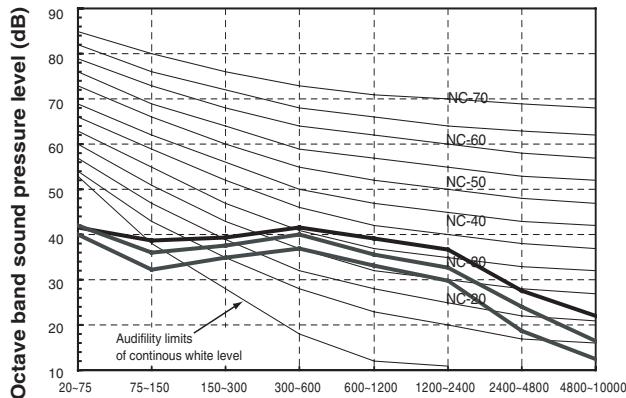
2-4-8. Sound Characteristics
RAV-SM562KRT-E
| Fan tap | H | M | L |
| Sound pressure level (dB(A)) | 39 | 36 | 33 |
RAV-SM802KRT-E
| Fan tap | H | M | L |
| Sound pressure level (dB(A)) | 45 | 41 | 36 |
3. Outdoor unit
3-1. Specifications 3-2
3-2. Dimension 3-3
3-3. Wiring diaaram 3-5
3-4. Sound characteristics 3-7
3-5. Capacity variation ratio according to temperature 3-8
3-1. Specifications
- Outdoor Unit Specifications
| Model name RAV- | SP562AT-E | SP802AT-E | SP1102AT-E | SP1402AT-E |
| Power supply | 1 phase 230V (220 - 240V) 50Hz (Power exclusive to outdoor is required.) |
| Compressor | Type | Hermetic compressor |
| Motor (kW) | 2.0 | 2.0 | 3.75 | 3.75 |
| Pole | 4 | 4 | 4 | 4 |
| Refrigerant charged (kg) | 1.5 | 2.1 | 2.95 | 2.95 |
| Refrigerant control | Pulse motor valve |
| Inter connecting pipe | Standard length (m) | 7.5 | 7.5 | 7.5 | 7.5 |
| Min. length (m) | 5.0 | 5.0 | 5.0 | 5.0 |
| Max. total length (m) | 50 | 50 | 70 | 70 |
| Additional refrigerant charge under long piping connector | 20g/m (21m to 50m) | 40g/m (31m to 50m) | 40g/m (31m to 70m) | 40g/m (31m to 70m) |
| Height difference | Outdoor lower (m) | 30 | 30 | 30 | 30 |
| Outdoor higher (m) | 30 | 30 | 30 | 30 |
| Outer dimension | Height (mm) | 795 | 795 | 1340 | 1340 |
| Width (mm) | 900 | 900 | 900 | 900 |
| Depth (mm) | 320 | 320 | 320 | 320 |
| Appearance | Silky shade (Muncel 1Y8.5/0.5) |
| Total weight (kg) | 55 | 62 | 95 | 95 |
| Heat exchanger | Finned tube |
| Fan unit | Fan | Propeller fan |
| Standard air flow (m³/min) | 57 | 57 | 125 | 125 |
| Motor (W) | 63 | 63 | 63 + 63 | 63 + 63 |
| Connecting pipe | Gas side (mm) | 12.7 | 15.9 | 15.9 | 15.9 |
| Liquid side (mm) | 6.4 | 9.5 | 9.5 | 9.5 |
| Sound pressure level | Cooling/Heating (dB·A) | 46/47 | 47/49 | 49/51 | 53/54 |
| Sound power level | Cooling/Heating (dB·A) | 63/64 | 64/66 | 66/68 | 70/71 |
| Outside air temperature, Cooling (°C) | 43 to -15 |
| Outside air temperature, Heating (°C) | 15 to -15 |
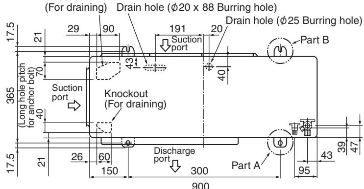
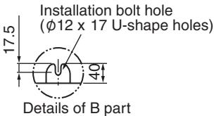
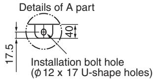
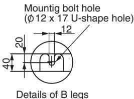
3-2. Dimension
RAV-SP562AT-E, RAV-SP802AT-E
Knockout
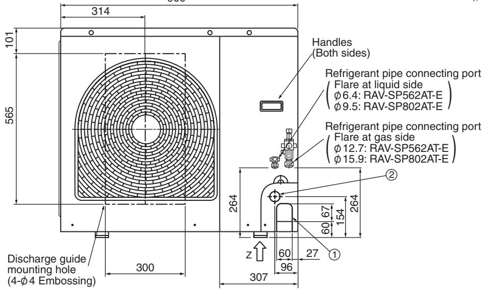
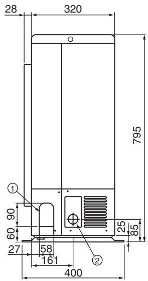
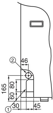
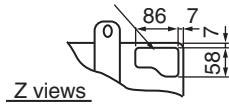
Knockout for lower piping
Space required for service
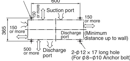
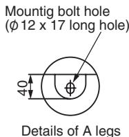
2-φ 12 x 17 U-shape holes (For φ8-φ10 Anchor bolt)
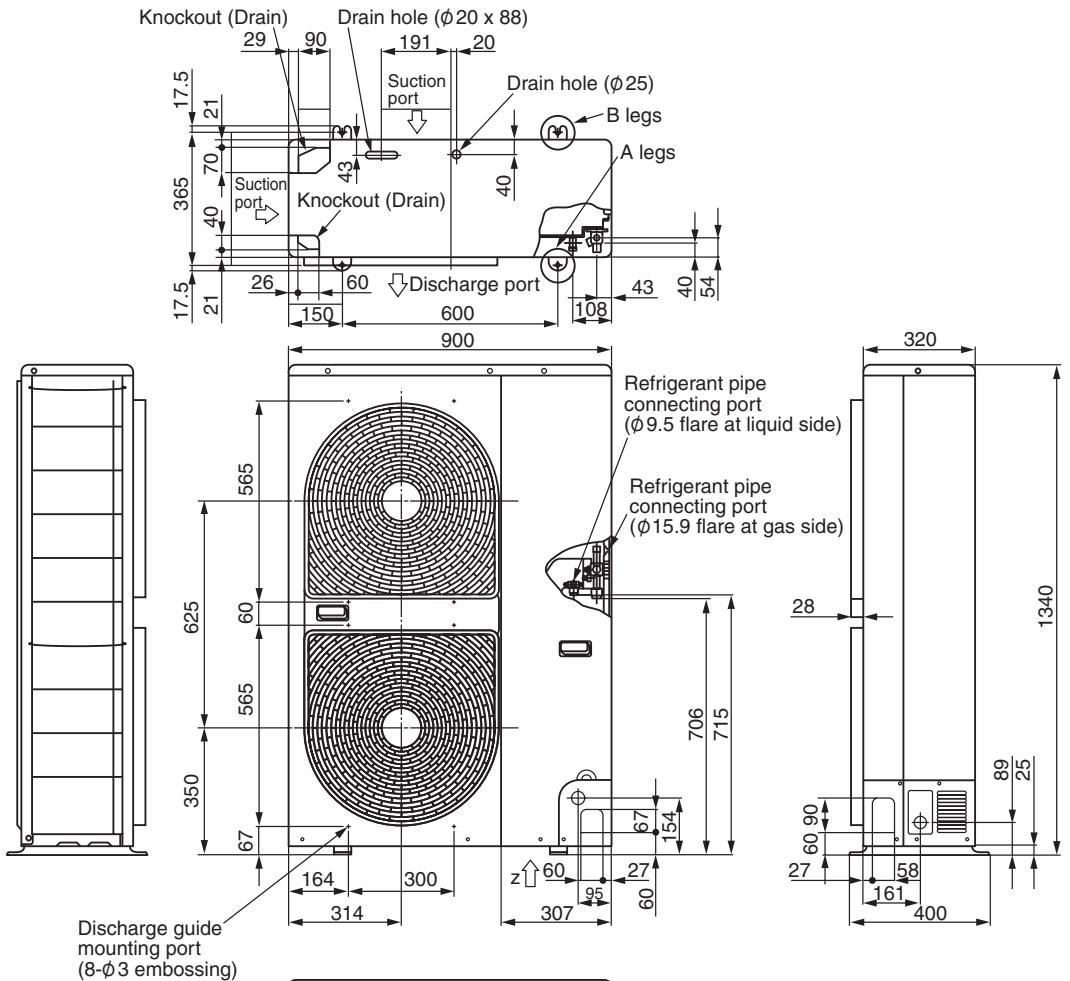
RAV-SP1102AT-E, RAV-SP1402AT-E
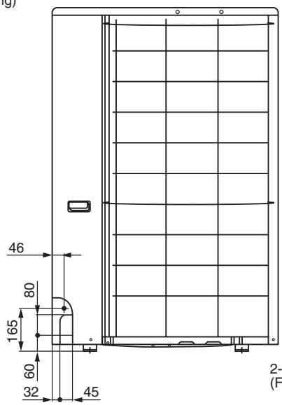
Space required for service
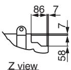
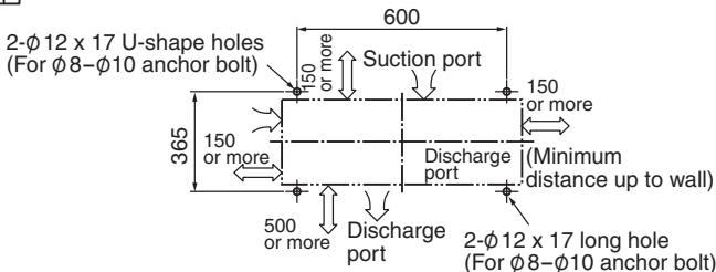
3-3. Wiring Diagram
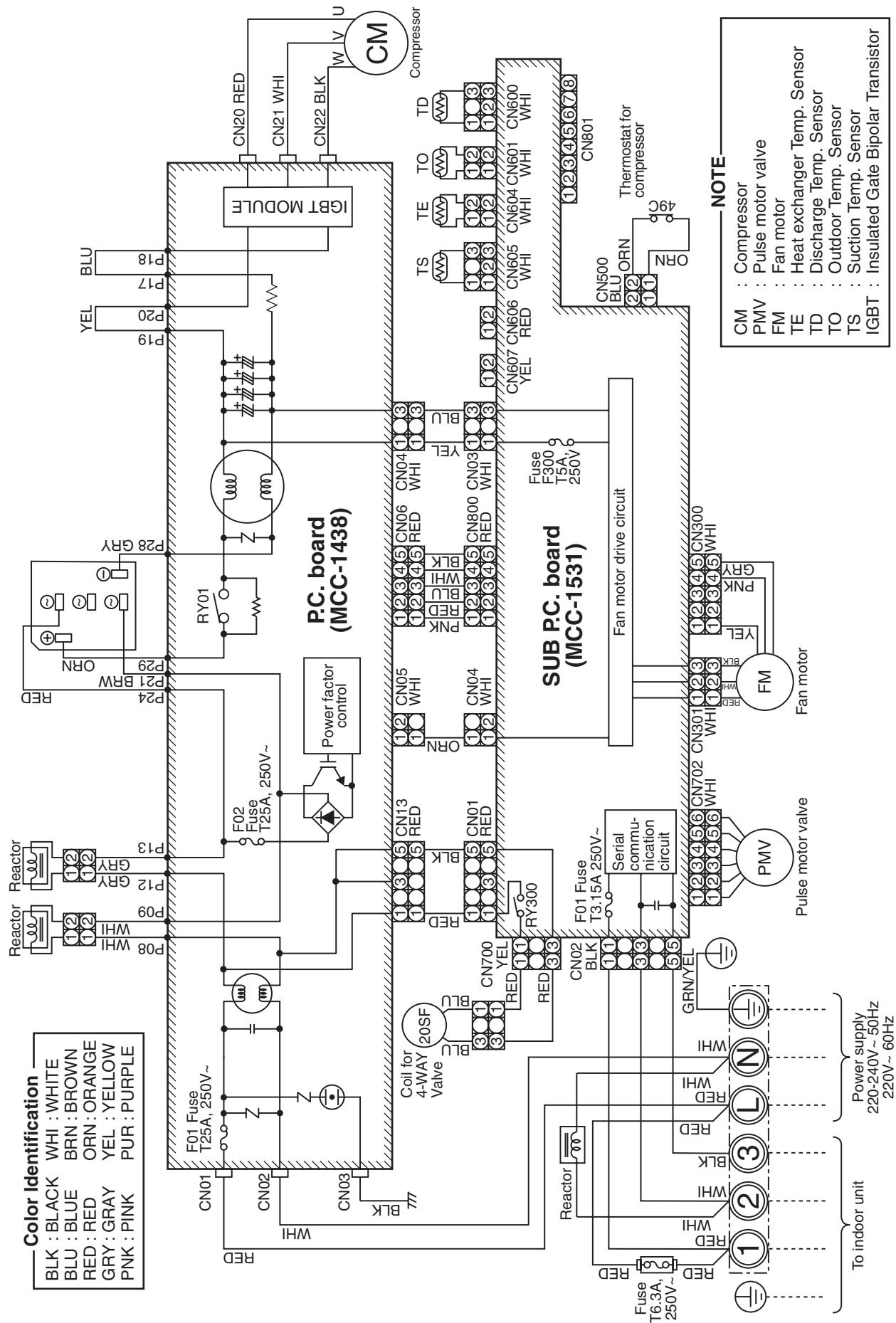
RAV-SP562AT-E, RAV-SP802AT-E
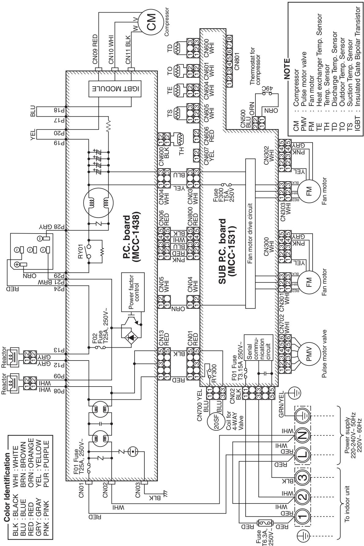
RAV-SP1102AT-E, RAV-SP1402AT-E
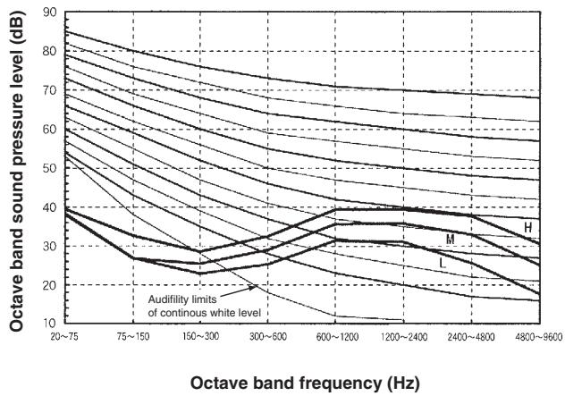
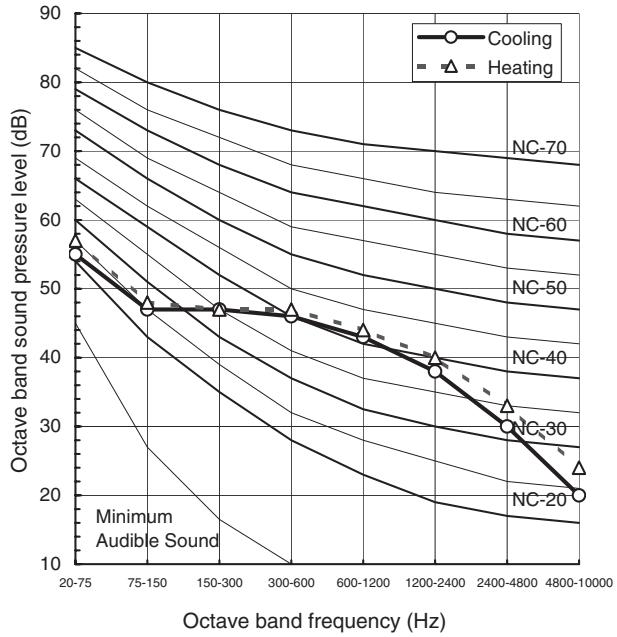
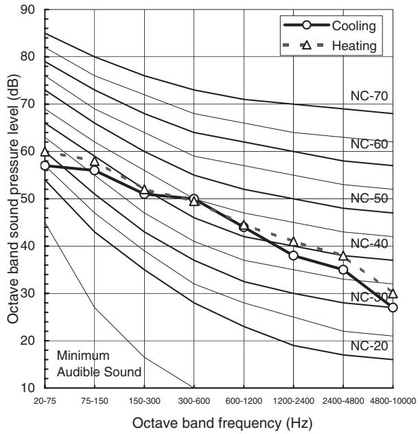
3-4. Sound Characteristics (NC Curve)
RAV-SP562AT-E
| Sound pressure level (dB(A)) | Cooling | Heating |
| 46 | 47 |
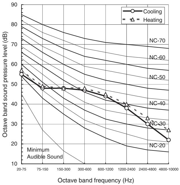
RAV-SP802AT-E
| Sound pressure level (dB(A)) | Cooling | Heating |
| 47 | 49 |
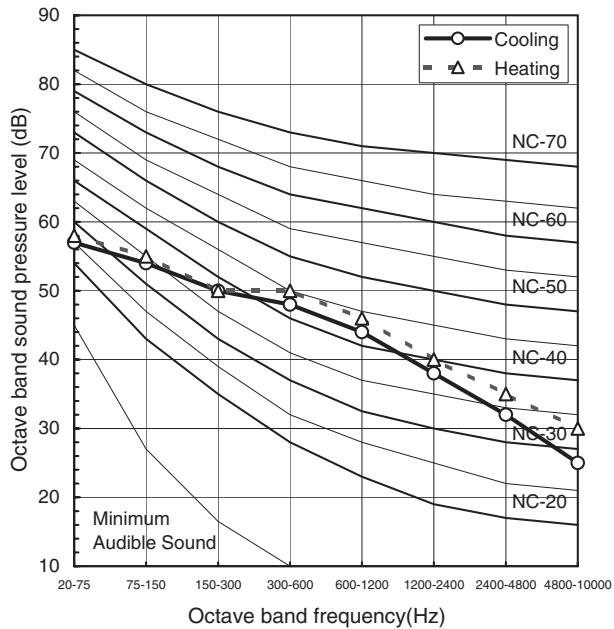
RAV-SP1102AT-E
| Sound pressure level (dB(A)) | Cooling | Heating |
| 49 | 51 |
RAV-SP1402AT-E
| Sound pressure level (dB(A)) | Cooling | Heating |
| 53 | 54 |
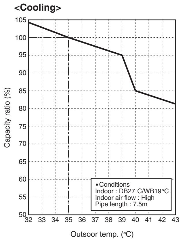
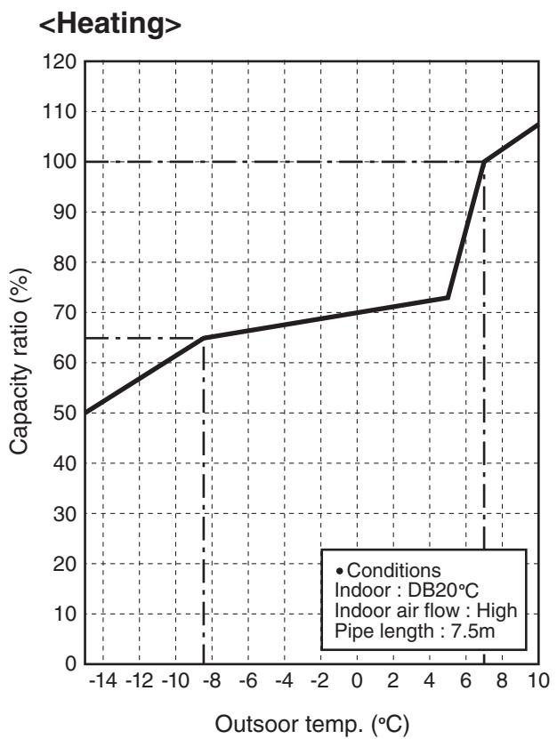
3-5. Capacity Variation Ratio According To Temperature
RAV-SP562AT-E, RAV-SP802AT-E, RAV-SP1102AT-E, RAV-SP1402AT-E
4. Controls
4-1. Remote controller line-up 4-2
4-2. Group control 4-3
4-3. Central control 4-3
4. Controls
4-1. Remote Controller Line-UP
| Remote controller & Adaptor | Indoor unit | 4-Way Cassette Type RAV-SM**2UT-ERAV-SP1102UT-E | Duct Type RAV-SM**2BT-E | Ceiling Type RAV-SM**2CT-E | High-Wall Type RAV-SM**2KRT-E | |
| RBC-AMT31E Wired remote controller | ● | ● | ● | ● | ● | |
| RBC-AS21E2 Simple wired remote controller | ● | ● | ● | ● | ● | |
| TBC-AX21U(W)-E2 Wireless remote controller kit | ● | — | — | — | — | |
| RBC-AX22CE2 Wireless remote controller kit | — | — | ● | — | — | |
| TCB-AX21E2 Wireless remote controller kit | — | ● | — | ● | ● | |
| RBC-EXW21E2 Weekly timer | ● | ● | ● | ● | ● | |
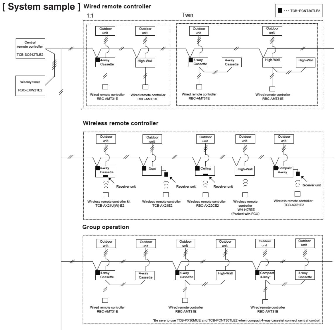
| TCB-SC642TLE2 Central remote controller | ● | ● | ● | ● | ● | |
| TCB-TC21LE2 Remote sensor | ● | ● | ● | ● | ● | |
| TCB-PCNT30TLE2 "1:1 model" connection interface (for connecting to central control wiring) | ● | ● | ● | ● | — | |
| WH-H2UE Wireless remote controller | — | — | — | ● | ● | |
Packed with FCU
| 4-Way Cassette Type | Duct Type | Ceiling Type | High-Wall Type | |
| Group control | ○ | ○ | ○ | ○ | |
| Central remote controller | ○
"1:1 model"
connection interface
TCB-PCNT30TLE2 | ○
"1:1 model"
connection interface
TCB-PCNT30TLE2 | ○
"1:1 model"
connection interface
TCB-PCNT30TLE2 | ○
Can connect without
"1:1 model"
connection interface | |
Auto Restart Operation How to set the AUTO RESET Function
| Indoor unit | Remote controller | Setting Procedure |
| 4-way cassette Type | RAV-SM**2UT-E | RBC-AMT31E | Set the code on wired remote controller.
0001 : Reset 0000 : none
*When the unit are shipped from the factory "Auto restart function" is set up "0000" operation. |
| Duct Type | RAV-SM**2BT-E | RBC-AMT31E | Set the code on wired remote controller.
0001 : Reset 0000 : none
*When the unit are shipped from the factory "Auto restart function" is set up "0000" operation. |
| Ceiling Type | RAV-SM**2CT-E | RBC-AMT31E | Set the code on wired remote controller.
0001 : Reset 0000 : none
*When the unit are shipped from the factory "Auto restart function" is set up "0000" operation. |
| High-wall Type | RAV-SM**2KRT-E | RBC-AMT31E | Set the code on wired remote controller.
0001 : Reset 0000 : none
*When the unit are shipped from the factory "Auto restart function" is set up "0000" operation. |
| | | |
4-2. Group Control
Max. 8 indoor units can be controlled by one remote controller on a group control.
Twin control of 1 by 1 model is one group control.
Header indoor unit controls indoor air temperature based on setting temperature of the remote controller.
[ System sample ]
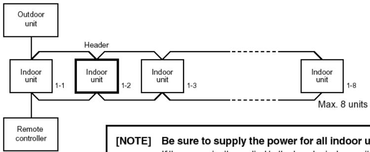
[NOTE] Be sure to supply the power for all indoor units on the group control. If the power isn't supplied to the header indoor unit, communication between indoor units and remote controller can't be performed.
4-3. Central Control
Connectable units
- Max.64 of indoor units or groups can be connected and controlled in one central remote controller.
- It count the number of the twin unit as the one
5. Accessories
5-1. Accessories 5-2
5-2. Drain up kit 5-4
5-3. Twin kit 5-5
5. Accessories
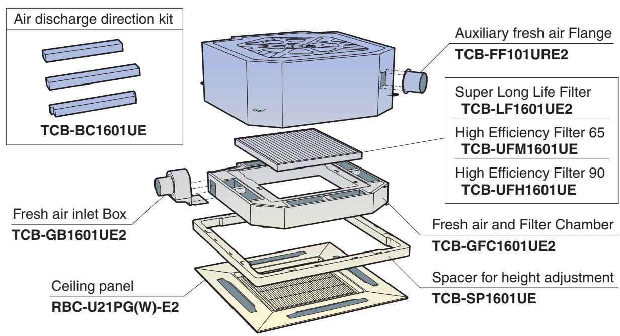
5-1. Accessories line up
4-way Cassette Type
| Parts Name | Model name | Notes | Remarks |
| Ceiling panel | RBC-U21PG(W)-E2 | Required accessory | |
| Super Long Life Filter | TCB-LF1601UE2 | Dust collecting effect : 50% (Weight method) *Not valid in combination with TCB-FM1601UE, TCB-UFH1601UE and TCB-BC1601UE | Use with TCB-GFC1601UE2 |
| High Efficiency Filter 65 | TCB-UFM1601UE | Dust collecting effect : 65% (NBS Colorimetric method) *Not valid in combination with TCB-LF1601UE2, TCB-UFH1601UE, TCB-FF101URE2 and TCB-BC1601UE | Use with TCB-GFC1601UE2 |
| High Efficiency Filter 90 | TCB-UFH1601UE | Dust collecting effect : 90% (NBS Colorimetric method) *Not valid in combination with TCB-LF1601UE2, TCB-UFM1601UE, TCB-FF101URE2 and TCB-BC1601UE | Use with TCB-GFC1601UE2 |
| Fresh air inlet Box | TCB-GB1601UE2 | For fresh air intake by using the knockout hole of Fresh air and filter chamber. (dia=100mm) *Not valid in combination with TCB-FF101URE2 and TCB-SP1601UE | Use with TCB-GFC1601UE2 |
| Frech air and Filter Chamber | TCB-GFC1601UE2 | For fresh air intake and installing high efficiency filter or super long filter *Not valid in combination with TCB-SP1601UE | |
| Auxiliary fresh air Flange | TCB-FF101URE2 | For easy fresh air intake by using the knockout hole of indoor unit.(dia=100mm) *Not valid in combination with TCB-GB1601UE2 | |
| Spacer for height adjustment | TCB-SP1601UE | Height = 500mm *Not valid in combination with TCB-GB1601UE2 and TCB-GFC1601UE2 | |
| Air discharge direction kit | TCB-BC1601UE | Air direction charge by cutting off air discharge port (3pcs) *Not valid in combination with TCB-LF1601UE2, TCB-UFM1601UE, TCB-UFH1601UE | |
■ Ceiling Type
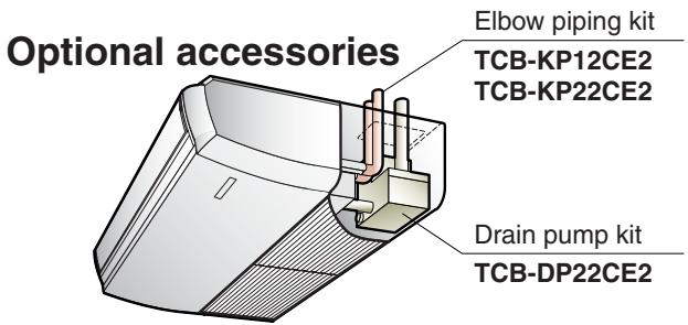
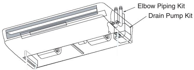
| Parts Name | Model name | Applied Model | Notes | Remarks |
| Drain Pump Kit | TCB-DP22CE2 | MMC-AP0151/0181H | Stand-up 600 or less (from bottom face of ceiling) | Use with TCB-KP12CE |
| MMC-AP0241H/0271/0361H/0481H | Use with TCB-KP22CE |
| Elbow Piping Kit | TCB-KP12CE2 | 2HP | Needed when Drain Pump Kit is used | |
| TCB-KP22CE2 | 3-5HP |
Duct Type
| Model name | Remarks |
| High Efficiency Filter 65 | TCB-UFM11BFCE | For rear suction (2P for 3HP) |
| TCB-UFM21BFCE | For rear suction (2P for 4-5HP) |
| TCB-UFM21BE | For Underside suction (for 2HP) |
| TCB-UFM31BE | For Underside suction (for 3HP) |
| TCB-UFM41BE | For Underside suction (for 4-5HP) |
| High Efficiency Filter 90 | TCB-UFH51BFCE | For rear suction (2P for 3HP) |
| TCB-UFH61BFCE | For rear suction (2P for 4-5HP) |
| TCB-UFH61BE | For Underside suction (for 2HP) |
| TCB-UFH71BE | For Underside suction (for 3HP) |
| TCB-UFH81BE | For Underside suction (for 4-5HP) |
5-2. Drain up kit
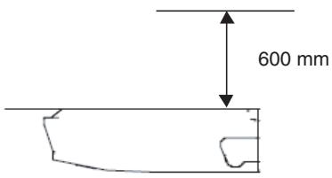
* A high-lift drain kit is available as an option (600mm)
| model name | Note | RAV- |
| SM56*CT-E | SM80*CT-E | SM110*CT-E | SM140*CT-E |
| Drain Pump Kit | | TCB-DP22CE2 |
| Elbow Piping Kit | Necessary when Drain Pump kit is used. | TCB-KP12CE2 | TCB-KP22CE2 |
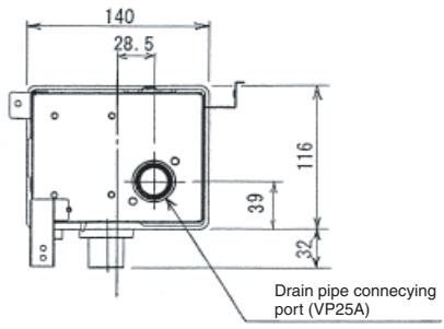
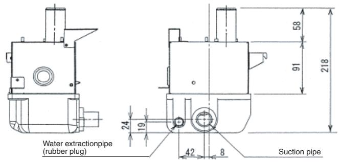
Dimension
Drain pump kit (TCB-DP22CE2)
Elbow piping kit (TCB-KP12CE2, TCB-KP22CE2)
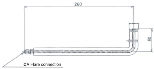
(Liquid side)
(Gas side)
| model | A | B |
| TCB-KP12CE2 | 6.4 | 12.7 |
| TCB-KP22CE2 | 9.5 | 15.9 |
5-3. Twin kit
- COMPONENT
The following parts are supplied as accessories of the branch pipes. Check them when opening the carton box.
| Part | Quantity | Shape | Use |
| Installation Instructions | 1 | This booklet | For installation works |
| Branch pipe | Gas side | 1 | | For refrigerant pipe branching and collection |
| Liquid side | 1 | |
| Noise filter | 2 | | For connection on the P.C. board |
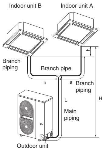
- REFRIGERANT PIPING
Tolerance of pipe length and pipe head
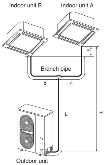
| Pipe Length (One Direction) | Height Difference | Remarks |
| Model (RAV-) | Full length L + a or L + b | Branch piping a, b | Difference of branch piping length b - a, or a - b | Outdoor Unit - Indoor Unit H | Between Indoor Units Dh |
| Outdoor Unit Installed Above Indoor Unit | Outdoor Unit Installed Below Indoor Unit |
| 1102AT 1402AT | Below 50m (actual length) | Below 15m (actual length) | Below 10m | Below 30m | Below 30m | Below 0.5m | Less than 10 bends |
CAUTION
Ensure that the shortest pipe length complies with the following: L + b ≥ 5m a≥b
When planning a layout for Units A and B, comply with the following:
- The lengths after branching ("a" and "b") should be equal if feasible. Install Units A and B so that the difference of the branching lengths becomes less than 10m if the lengths cannot be equal due to the branch pipe position.
- Install Units A and B on the same level. If Units A and B cannot be installed on the same level, the difference in level should be limited to 0.5m or less.
3.Be certain to install Units A and B in the same room. Units A and B cannot be operated independently each other.
Piping materials and sizes
Use copper tube of Copper and copper alloy seamless pipes and tubes, with 40mg / 10m or less in the amount of oil stuck on inner walls of pipe and 0.8mm in pipe wall thickness for diameters 6.4, 9.5 and 12.7mm and 1.0mm , for diameter 15.9mm . Never use pipes of thin wall thickness such as 0.7mm .
| Model (RAV -) | 1102AT | 1402AT |
| Pipe side | Gas side | Main piping | Ø15.9 (1.0) |
| Branch piping | Ø12.7 (0.8) | Ø15.9 (1.0) |
| Liquid side | Main piping | Ø9.5 (0.8) |
| Branch piping | Ø6.4 (0.8) | Ø9.5 (0.8) |
In parentheses ( ) are wall thickness
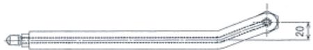
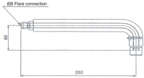
Branch pipe
Now the refrigerant pipe is installed using branch pipes supplied as accessories.
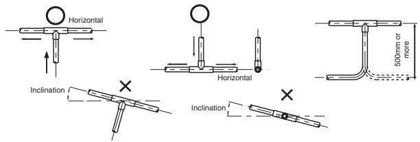
Bend and adjust the refrigerant piping so that the branch pipes and pipe after branching become horizontal.
Fix the branch pipes onto a wall in a ceiling or onto a column.
Provide a straight pipe longer than 500mm in length as the main piping of the branches.
Additional Refrigerant Amount
Do not remove the refrigerant even if the additional refrigerant amount becomes minus result as a result of calculations by the following formula and operate the air conditioner as it is.
| Additional refrigerant amount (kg) = Main piping additional refrigerant amount (kg) + Branch piping additional refrigerant amount (kg) = A x (L - 18) + B x (a + b - 4) |
A: Additional refrigerant amount per meter of actual main piping length (kg)
B: Additional refrigerant amount per meter of actual branch piping length (kg)
L: Actual length of main piping (m)
a, b: Actual length of branch piping (m)
| Standar d piping length | Additional refrigerant amount per Meter (kg/m) |
| Main piping | Branch piping | A | B |
| 1102AT | 18m | 2m | 0.040 | 0.020 |
| 1402AT | 18m | 2m | 0.040 | 0.040 |
CAUTION
- Be certain to write the additional refrigerant amount, pipe length (actual length), head and other specification on the nameplate put on the outdoor unit for recording.
- Seal the correct amount of additional refrigerant in the system.
Indoor Unit P.C electrical parts
This work is unnecessary for Hi-Wall Type.
This work is necessary for each indoor unit.
- Disconnect the read wire between remote control terminal and CN41 (RC) connector on the P.C/board.
P.C board of Indoor Unit
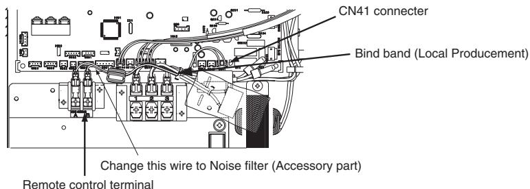
- Connect the Noise Filter between remote control terminal and CN41 (RC) connector on the P.C/board.
3.Bind this wire and main terminal wire by bind band.
Wiring Diagram
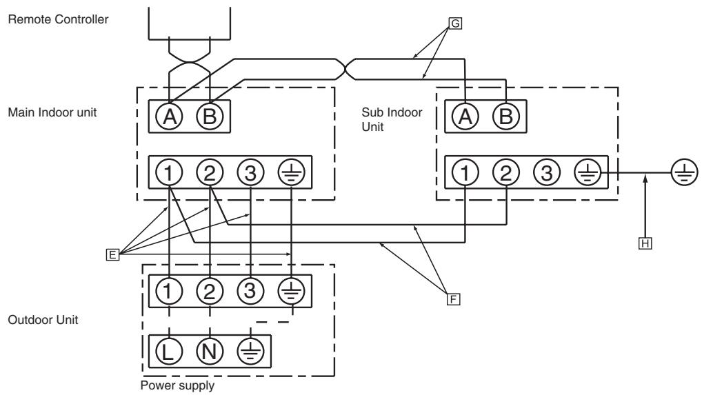
Wiring Specification
Specification of Wires Between Units and Numbers of Wires.
| Outdoor unit - indoor unit (main unit) E | No. of wires | 4 (Include ground wire) |
| Wire diameter | H07RN-F or 245IEC66 1.5mm² or more |
| Indoor unit - indoor unit (main unit) F | No. of wires | 2 |
| Wire diameter | H07RN-F or 245IEC66 1.5mm² or more |
| Remote control wiring G | No. of wires | 2 |
| Wire diameter | Between 0.5mm² and 2mm² (up to 200m) |
| Grounding wire of indoor sub unit H | H07RN-F or 245IEC66 1.5mm² or more |
Procure necessary parts and perform all connection work locally.
Super Digital Inverter
Engineering Data Book