USER MANUAL MMK-AP0153H TOSHIBA
Leading Innovation >>
SUPER MODULAR MULTI SYSTEM AIR CONDITIONER
Installation Manual
HFC
R410A
SUPER
SUPER MODULAR MULTI
Indoor Unit
Model name:
High-Wall Type
MMK-AP0073H, MMK-AP0073H-C
MMK-AP0093H, MMK-AP0093H-C
MMK-AP0123H, MMK-AP0123H-C
MMK-AP0153H, MMK-AP0153H-C
MMK-AP0183H, MMK-AP0183H-C
MMK-AP0243H, MMK-AP0243H-C
For commercial use
Pour usage commercial
Please read this Installation Manual carefully before installing the Air Conditioner.
- This Manual describes the installation method of the indoor unit.
- For installation of the outdoor unit, follow the Installation Manual attached to the outdoor unit.
ADOPTION OF NEW REFRIGERANT
This Air Conditioner is a new type which adopts a new refrigerant HFC (R410A) instead of the conventional refrigerant R22 in order to prevent destruction of the ozone layer.
Contents
1 ACCESSORY PARTS 2
2 PRECAUTIONS FOR SAFETY 3
3 SELECTION OF INSTALLATION PLACE 5
4 INSTALLATION OF INDOOR UNIT 7
5 CUTTING A HOLE AND MOUNTING INSTALLATION PLATE 8
6 Piping and Drain Hose Installation 9
7INDOOR UNIT FIXING 12
8 DRAINAGE 12
9 REFRIGERANT PILING 13
10 ELECTRIC WORK 15
11 APPLICABLE CONTROLS 21
12 TEST RUN 24
13 TROUBLE SHOOTING 26
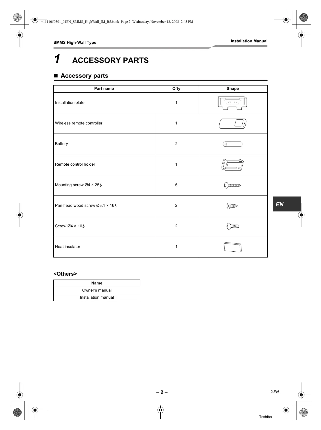
1 ACCESSORY PARTS
Accessory parts
| Part name | Q'ty | Shape |
| Installation plate | 1 | |
| Wireless remote controller | 1 | |
| Battery | 2 | |
| Remote control holder | 1 | |
| Mounting screw Ø4 × 25l | 6 | |
| Pan head wood screw Ø3.1 × 16l | 2 | × |
| Screw Ø4 × 10l | 2 | |
| Heat insulator | 1 | |
| Name |
| Owner's manual |
| Installation manual |
2 PRECAUTIONS FOR SAFETY
- Ensure that all Local, National and International regulations are satisfied.
- Read this "PRECAUTIONS FOR SAFETY" carefully before Installation.
- The precautions described below include the important items regarding safety. Observe them without fail.
- After the installation work, perform a trial operation (test run) to check for any problem. Follow the Owner's Manual to explain how to use and maintain the unit to the customer.
- Turn off the main power supply switch (or breaker) before the unit maintenance.
- Ask the customer to keep the Installation Manual together with the Owner's Manual.

WARNING
- Ask an authorized dealer or qualified installation professional to install (including moving)/ maintain the air conditioner.
Inappropriate installation may result in water leakage, electric shock or fire.
- Be sure to connect earth wire. (grounding work)
Incomplete grounding cause an electric shock.
Do not connect ground wires to gas pipes, water pipes, lightning rods or ground wires for telephone wires.
- Turn off the main power supply switch or breaker before attempting any electrical work.
Make sure all power switches are off. Failure to do so may cause electric shock.
- Install the refrigerant pipe securely during the installation work before operating the air conditioner.
If the air conditioner is operated with the valve open and without the refrigerant pipe, the compressor sucks air and the refrigeration cycle is over pressurized, which may cause a burst or injury.
- When moving the air conditioner for the installation into another place, be very careful not to enter any gaseous matter other than the specified refrigerant into the refrigeration cycle.
If air or any other gas is mixed in the refrigerant, the gas pressure in the refrigeration cycle becomes abnormally high and it resultingly causes pipe burst and injuries on persons.
- Perform installation work properly according to the Installation Manual.
Inappropriate installation may result in water leakage, electric shock or fire.
-
When the air conditioner is installed in a small room, provide appropriate measures to ensure that the concentration of refrigerant leakage occur in the room does not exceed the critical level.
-
Install the air conditioner securely in a location where the base can sustain the weight adequately.
-
Perform the specified installation work to guard against an earthquake.
If the air conditioner is not installed appropriately, accidents may occur due to the falling unit.
- If refrigerant gas has leaked during the installation work, ventilate the room immediately.
If the leaked refrigerant gas comes in contact with fire, noxious gas may generate.
- After the installation work, confirm that refrigerant gas does not leak.
If refrigerant gas leaks into the room and flows near a fire source, such as a cooking range, noxious gas might generate.
- Electrical work must be performed by a qualified electrician in accordance with the Installation Manual. Make sure the air conditioner uses an exclusive power supply.
An insufficient power supply capacity or inappropriate installation may cause fire.
- Use the specified wires for wiring connect the terminals securely fix.
To prevent external forces applied to the terminals from affecting the terminals.
- Conform to the regulations of the local electric company when wiring the power supply.
Inappropriate grounding may cause electric shock.
- For the refrigerant recovery work (collection of refrigerant from the pipe to the compressor), stop the compressor before disconnecting the refrigerant pipe.
If the refrigerant pipe is disconnected while the compressor is working with the valve open, the compressor sucks air and the refrigeration cycle is over pressurized, which may cause a burst or injury.

CAUTION
New Refrigerant Air Conditioner Installation
- THIS AIR CONDITIONER ADOPTS THE NEW HFC REFRIGERANT (R410A) WHICH DOES NOT DESTROY OZONE LAYER.
- The characteristics of R410A refrigerant are; easy to absorb water, oxidizing membrane or oil, and its pressure is approx. 1.6 times higher than that of refrigerant R22. Accompanied with the new refrigerant, refrigerating oil has also been changed. Therefore, during installation work, be sure that water, dust, former refrigerant, or refrigerating oil does not enter the refrigerating cycle.
- To prevent charging an incorrect refrigerant and refrigerating oil, the sizes of connecting sections of charging port of the main unit and installation tools are changed from those for the conventional refrigerant.
- Accordingly the exclusive tools are required for the new refrigerant (R410A).
- For connecting pipes, use new and clean piping designed for R410A, and please care so that water or dust does not enter.
To Disconnect the Appliance from Main Power Supply.
- This appliance must be connected to the main power supply by means of a switch with a contact separation of at least 3mm .
- The installation fuse must be used for the power supply line of this conditioner.
- Tighten the flare nut with a torque wrench in the specified manner.
Excessive tightening of the flare nut may cause a crack in the flare nut after a long period, which may result in refrigerant leakage.
- Wear heavy gloves and a long sleeve shirt during the installation work to avoid injury.
3 SELECTION OF INSTALLATION PLACE

WARNING
- Install the air conditioner at enough strong place to withstand the weight of the unit.
If the strength is not enough, the unit may fall down resulting in injury.

CAUTION
- Do not install the air conditioner in a location subject to a risk of exposure to a combustible gas.
If a combustible gas leaks and stays around the unit, a fire may occur.
Upon approval of the customer, install the air conditioner in a place that satisfies the following conditions.
- Place where the unit can be installed horizontally.
- Place where a sufficient servicing space can be ensured for safety maintenance and check.
- Place where drained water will not cause any problem.
Avoid installing in the following places.
- Place exposed to air with high salt content (seaside area), or place exposed to large quantities of sulfide gas (hot spring).
(Should the unit be used in these places, special protective measures are needed.)
- A restaurant kitchen where a lot of oil is used or place near machines in a factory (Oil adhering to the heat exchanger and resin part (cross flow fan) in the indoor unit may reduce the performance, generate mist or dew drop, or deform or damage resin parts.)
- Place where organic solvent is used nearby.
- Place close to a machine generating high frequency.
- Place where the discharged air blows directly into the window of the neighbour house. (Outdoor unit)
- Place where noise of the outdoor unit is easily transmitted. (When install the outdoor unit on the boundary with the neighbour, pay due attention to the level of noise.)
- Place with poor ventilation.
- Do not use the air conditioner for special purposes such as preserving food, precision instruments, or art objects, or where breeding animals or growing plants are kept. (This may degrade the quality of preserved materials.)
- Place where any of high-frequency appliances (including inverter devices, private power generators, medical equipment, and communication equipment) and inverter-type fluorescent light is installed. (A malfunction of the air conditioner, abnormal control, or problems due to noise to such appliances/ equipment may occur.)
- When the wireless remote controller is used in a room equipped with an inverter-type fluorescent light or at a place exposed to direct sunlight, signals from the remote controller may not be received correctly.
- Place where organic solvent is used.
- Place near a door or window exposed to humid outside air (Dew dropping may form.).
- Place where special spray is used frequently.
Installation diagram of Indoor and outdoor units
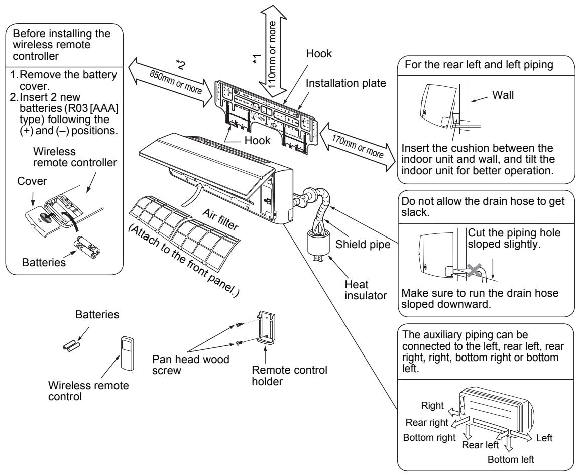
Installation space
The indoor unit shall be installed so that its top surface comes at a height of 2m or more.
Also it must be avoided to put anything on top of the indoor unit.
1 Reserve space required to install the indoor unit and for service work.
Keep 110mm or more for clearance between top plate of the indoor unit and the ceiling surface.
2 Provide a space as shown for service clearance for the cross flow fan.
Installation place
- A place which provides the spaces around the indoor unit as shown in the above diagram.
- A place where there is no obstacle near the air inlet and outlet.
- A place that allows easy installation of the piping to the outdoor unit.
- A place which allows the front panel to be opened.

CAUTION
- Direct sunlight to the indoor unit's wireless receiver should be avoided.
- The microprocessor in the indoor unit should not be too close to RF noise sources. (For details, see the owner's manual.)
■ Wireless remote controller
- A place where there are no obstacles such as a curtain that may block the signal from the indoor unit.
- Do not install the remote controller in a place exposed to direct sunlight or close to a heating source, such as a stove.
- Keep the remote controller at least 1m apart from the nearest TV set or stereo equipment.
(This is necessary to prevent image disturb-bounces or noise interference.)
- The location of the remote controller should be determined as shown below.
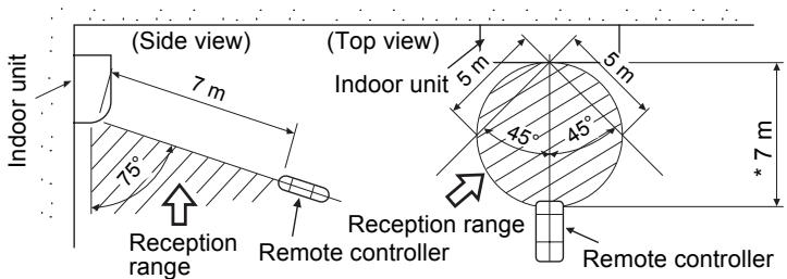
*: Axial distance
4 INSTALLATION OF INDOOR UNIT

WARNING
Install the air conditioner certainly to sufficiently withstand the weight.
If the strength is insufficient, the unit may fall down resulting in human injury.
Perform a specified installation work to guard against strong wind or earthquake.
An incomplete installation can cause accidents by the units falling and dropping.
REQUIREMENT
Strictly comply with the following rules to prevent damage of the indoor units and human injury.
- Do not put a heavy article on the indoor unit. (Even units are packaged)
- Carry in the indoor unit as it is packaged if possible. If carrying in the indoor unit unpacked by necessity, be sure to use buffering cloth, etc. to not damage the unit.
- To move the indoor unit, do not apply force to the refrigerant pipe, drain pan, foamed parts, or resin parts, etc.
- Carry the package by two or more persons, and do not bundle it with plastic band at positions other than specified.
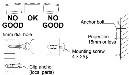
Be careful to the following items when installing the unit.
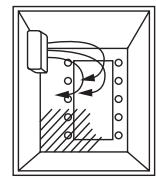
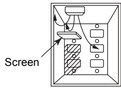
- Considering air discharge direction, select an installation place where discharge air can circulate evenly in a room. Avoid to install the unit at place with "NO GOOD" mark in the right figure.
OK
Good installation place Cooled well all over.
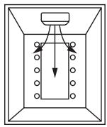
NO GOOD
Bad installation place
Not cooled well.
5 CUTTING A HOLE AND MOUNTING INSTALLATION PLATE
Cutting a hole
In case of installing the refrigerant pipes from the rear:
- Decide the hole position for piping at 180mm from the arrow mark () on the installation plate and drill a hole at a slight downward slant toward outdoor side. Pipe hole; dia.65mm: AP007-AP018 type Pipe hole; dia.80mm: AP024 type
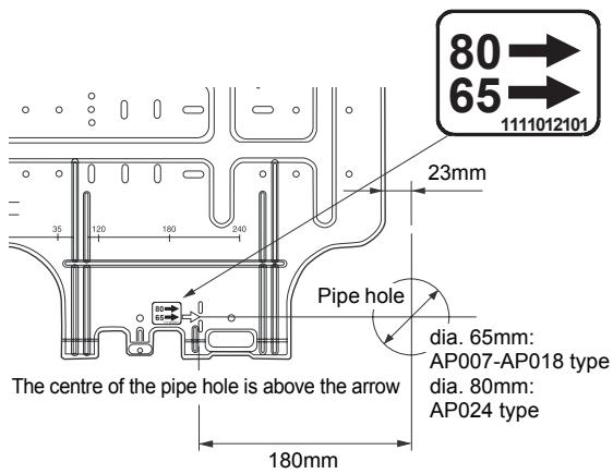
NOTE
- When drilling a wall that contains a metal lath, wire lath or metal plate, be sure to use a pipe hole brim ring sold separately.
Mounting the installation plate
Be sure that the installation plate is fix to the wall with screws to make the indoor unit fit to the wall.
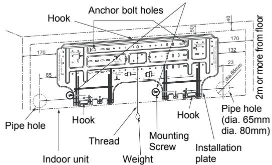
When the installation plate is directly mounted on the wall
- Securely fit the installation plate onto the wall by screwing it in the upper and lower parts to hook up the indoor unit.
- To mount the installation plate on a concrete wall with anchor bolts, utilize the anchor bolt holes as illustrated in the above figure.
- Install the installation plate horizontally in the wall.
CAUTION
When installing the installation plate with a mounting screw, do not use the anchor bolt hole. Otherwise the unit may fall down and result in personal injury and property damage.
CAUTION
Failure to firmly install the unit may result in personal injury and property damage if the unit falls.
- In case of block, brick, concrete or similar type walls, make 5mm dia. holes in the wall.
- Insert clip anchors for appropriate mounting screws.
NOTE
- Secure four corners and lower parts of the installation plate with 6 mounting screws to install it.
6 Piping and Drain Hose Installation
- Apply heat-insulation for both refrigerant pipe and drain hose surely so that no dew generates inside of the equipment. (Use polyethylene foam for insulating material.)
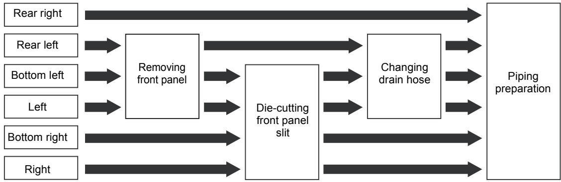
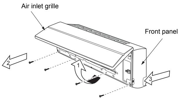
1. Remove the front panel
The front panel must be removed for piping connections in the left, bottom left, and rear left directions.
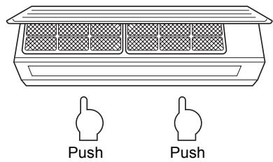
- Open the air inlet grille upward.
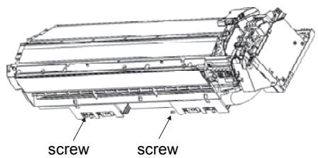
- Remove the four screws securing the front panel.
- Slightly open the lower part of the front panel, and then pull the upper part of the front panel toward you to remove it from the rear plate.
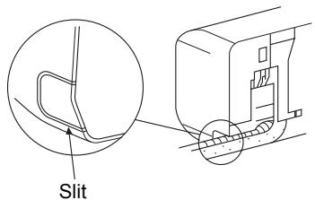
2. Die-cutting front panel slit
Cut out the slit on the leftward or right side of the front panel for the left or right connection and the slit on the bottom left or right side of the front panel for the bottom left or right connection with a pair of nippers.
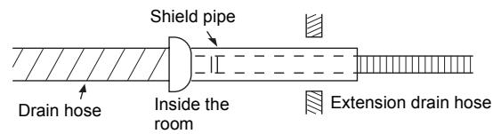
3. Changing drain hose
For leftward connection, bottom-leftward connection and rear leftward connection's piping, it is necessary to change the drain hose and drain cap.
Without changing the drain hose position, the indoor unit will not fit to the wall.
How to remove the drain hose
- The drain hose can be removed by removing the screw securing the drain hose and then pulling out the drain hose.
- When removing the drain hose, be careful of any sharp edges of steel plate. The edges can injuries.
- To install the drain hose, insert the drain hose firmly until the connection part contacts with heat insulator, and the secure it with original screw.
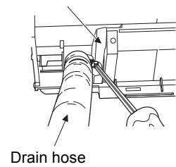
Heat insulator
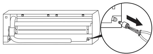
How to remove the drains cap
Clip the drain cap by needle-nose pliers and pull out.
How to fix the drains cap
1) Insert hexagonal wrench (dia. 4mm) in a centre head.
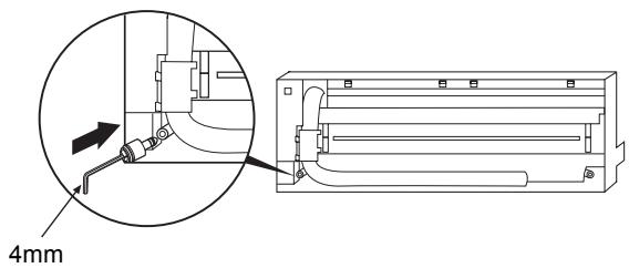
2) Firmly insert drains cap.
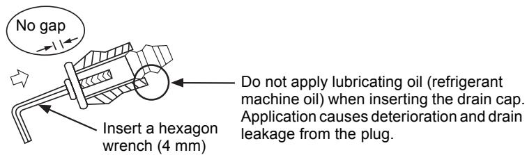

CAUTION
Firmly insert the drain hose and drain cap; otherwise, water may leak.
How to remove the drain hose
1) Remove the front panel.
2) Remove the screws of drain hose.
3) Pull out the drain hose.
How to fix the drain hose
1) Put the drain hose.
2) Screw the drain hose to the indoor unit.
3) Install the front panel.
In case of right or left piping
After scribing slits of the front panel with a knife or a marking-off pin, cut them with a pair of nippers or an equivalent tool.
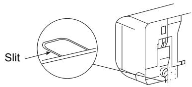
In case of bottom right or bottom left piping
- After scribing slits of the front panel with a knife or a marking-off pin, cut them with a pair of nippers or an equivalent tool.
Left-hand connection with piping
Bend the connecting pipe so that it is laid within 43mm above the wall surface. If the connecting pipe is laid exceeding 43mm above the wall surface, the indoor unit may unstably be set on the wall. When bending the connecting pipe, make sure to use a spring bender so as not to crush the pipe.
Bend the connection pipe within a radius of 30~mm
To connect the pipe after installation of the unit (figure)
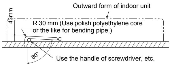
NOTE
If the pipe is bent incorrectly, the indoor unit may unstably be set on the wall.
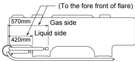
After passing the connecting pipe through the pipe hole, connect the connecting pipe to the auxiliary pipes and wrap the facing tape around them.

CAUTION
- Bind the auxiliary pipes (two) and power supply wiring and control wiring with facing tape tightly. In case of leftward piping and rear leftward piping, bind the auxiliary pipes (two) only with facing tape.
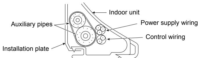
- Carefully arrange pipes so that any pipe does not stick out of the rear plate of the indoor unit.
- Carefully connect the auxiliary pipes and connecting pipes to one another and cut off the insulating tape wound on the connecting pipe to avoid double-taping at the joint, moreover, seal the joint with the vinyl tape, etc.
- Since dew results in a machine trouble, make sure to insulate both the connecting pipes. (Use polyethylene foam as insulating material.)
- When bending a pipe, carefully do it, not to crush it.
7 INDOOR UNIT FIXING
- Pass the pipe through the hole in the wall, and hook the indoor unit on the installation plate at the upper hooks.
- Swing the indoor unit to right and left to confirm that it is firmly hooked up on the installation plate.
- While pressing the indoor unit onto the wall, hook it at the lower part on the installation plate. Pull the indoor unit toward you to confirm that it is firmly hooked up on the installation plate.
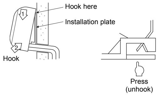
- For detaching the indoor unit from the installation plate, pull the indoor unit toward you while pushing its bottom up at the specified parts.
REQUIREMENT
The lower part of indoor unit may float, due to the condition of piping and you cannot fix it to the installation plate. In that case, use the screws provided to fix the unit and the installation plate. Especially when the pipes are pulled out from the left side, the unit must be screwed to the installation plate.
8 DRAINAGE
- Run the drain hose sloped downwards.
NOTE
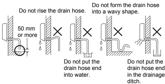

CAUTION
Arrange the drain pipe for proper drainage from the unit.
Improper drainage can result in dew-dropping.
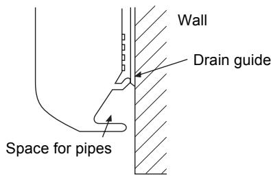
This air conditioner has the structure designed to drain water collected from dew, which forms on the back of the indoor unit, to the drain pan.
Therefore, do not store the power cord and other parts at a height above the drain guide.
9 REFRIGERANT PIPING
Refrigerant Piping
- Use copper pipe with 0.8 ~mm or more thickness. (In case pipe size is dia. 15.9, with 1.0 ~mm or more.)
- Flare nut and flare works are also different from those of the conventional refrigerant. Take out the flare nut attached to the main unit of the air conditioner, and use it.
REQUIREMENT
When the refrigerant pipe is long, provide support brackets at intervals of 2.5 to 3m to clamp the refrigerant pipe. Otherwise, abnormal sound may be generated.

CAUTION
IMPORTANT 4 POINTS FOR PIPING WORK
- Remove dust and moisture from the inside of the connecting pipes.
- Tight connection (between pipes and unit)
- Evacuate the air in the connecting pipes using VACUUM PUMP.
- Check the gas leakage. (Connected points)
Pipe size
(dia.: mm)
| MMK- | AP007 to AP012 type | AP015 to AP018 type | AP024 type |
| Gas side | 9.5 | 12.7 | 15.9 |
| Liquid side | 6.4 | 6.4 | 9.5 |
■ Permissible Piping Length and Height Difference
They vary according to the outdoor unit.
For details, refer to the Installation Manual attached to the outdoor unit.
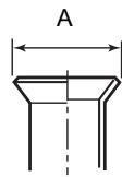
Flaring
- Cut the pipe with a pipe cutter.
Remove burrs completely.
Remaining burrs may cause gas leakage.
- Insert a flare nut into the pipe, and flare the pipe. As the flaring sizes of R410A differ from those of refrigerant R22, the flare tools newly manufactured for R410A are recommended.
However, the conventional tools can be used by adjusting projection margin of the copper pipe.
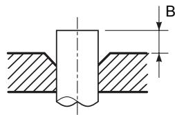
Projection margin in flaring: B (Unit: mm)
Rigid (Clutch type)
| Outer dia. of copper pipe | R410A tool used | Conventional tool used |
| R410A | R410A |
| 6.4, 9.5 | 0 to 0.5 | 1.0 to 1.5 |
| 12.7, 15.9 |
Flaring dia. meter size: A (Unit: mm)
| Outer dia. of copper pipe | A+0.4 |
| R410A |
| 6.4 | 9.1 |
| 9.5 | 13.2 |
| 12.7 | 16.6 |
| 15.9 | 19.7 |
- In case of flaring for R410A with the conventional flare tool, pull it out approx.
0.5 mm more than that for R22 to adjust to the specified flare size.
The copper pipe gauge is useful for adjusting projection margin size.
Tightening connection

CAUTION
- Do not apply excessive torque. Otherwise, the nut may crack depending on the conditions.
(Unit:N·m)
| Outer dia. of copper pipe | Tightening torque |
| 6.4 mm (dia.) | 14 to 18 (1.4 to 1.8 kgf*m) |
| 9.5 mm (dia.) | 33 to 42 (3.3 to 4.2 kgf*m) |
| 12.7 mm (dia.) | 50 to 62 (5.0 to 6.2 kgf*m) |
| 15.9 mm (dia.) | 68 to 82 (6.8 to 8.2 kgf*m) |
Tightening torque of flare pipe connections
Pressure of R410A is higher than that of R22.
(Approx. 1.6 times) Therefore, using a torque wrench, tighten the flare pipe connecting sections which connect the indoor and outdoor units of the specified tightening torque.
Incorrect connections may cause not only a gas leak, but also a trouble of the refrigeration cycle.
Align the centres of the connecting pipes and tighten the flare nut as far as possible with your fingers. Then tighten the nut with a spanner and torque wrench as shown in the figure.
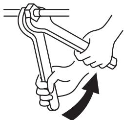
Work using double spanner
REQUIREMENT
Tightening with an excessive torque may crack the nut depending on installation conditions.
Tighten the nut within the specified tightening torque.
Piping with outdoor unit
- Shape of valve differs according to the outdoor unit.
For details of installation, refer to the Installation Manual of the outdoor unit.
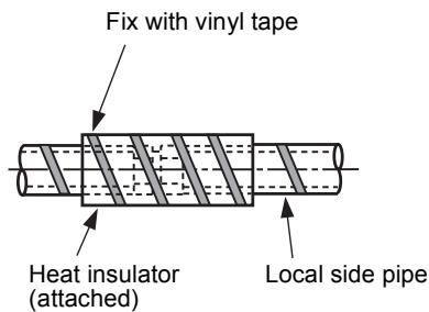
Heat insulation
Heat insulation for the pipes should be done separately for the liquid side and gas side. Because both of the liquid and gas side pipes become a low temperature during cooling operation, sufficient heat insulation should be done to prevent condensation.
- Heat insulator with a heat resistance of 120^ or more must be used for the gas side pipe.
- The pipe connection section of the indoor unit must be heat insulated securely and compactly with the attached heat insulator.
Airtight test/Air purge, etc.
For airtight test, air purge, addition of refrigerant, and gas leak check, follow the Installation Manual attached to the outdoor unit.
- Open fully valves of the outdoor unit
Gas leak check
Check with a leak detector or soap water whether gas leaks or not, from the pipe connecting section or cap of the valve.
REQUIREMENT
Use a leak detector manufactured exclusively HFC refrigerant (R410A, R134a, etc.).
10 ELECTRIC WORK

WARNING
- Using the specified wires, ensure to connect the wires, and fix wires securely so that the external tension to the wires do not affect the connecting part of the terminals. Incomplete connection or fixation may cause a fire, etc.
- Be sure to connect earth wire. (grounding work) Incomplete grounding cause an electric shock. Do not connect ground wires to gas pipes, water pipes, lightning rods or ground wires for telephone wires.
- Appliance shall be installed in accordance with national wiring regulations.
Capacity shortage of power circuit or incomplete installation may cause an electric shock or a fire.

CAUTION
- If incorrect/incomplete wiring is carried out, it will cause an electrical fire or smoke.
- Be sure to install an earth leakage breaker that is not tripped by shock waves. If an earth leakage breaker is not installed, an electric shock may be caused.
- Be sure to use the cord clamps attached to the product.
- Do not damage or scratch the conductive core and inner insulator of power and interconnecting wires when peeling them.
- Use the power cord and Inter-connecting wire of specified thickness, type, and protective devices required.
- Never connect 220–240V power to the terminal blocks (U1, U2, A, B, etc.) for control wiring.
(Otherwise, the system will fail.)
REQUIREMENT
- For power supply wiring, strictly conform to the Local Regulation in each country.
- For wiring of power supply of the outdoor units, follow the Installation Manual of each outdoor unit.
- Perform the electric wiring so that it does not come to contact with the high-temperature part of the pipe.
The coating may melt resulting in an accident.
After connecting wires to the terminal blocks, provide a trap and fix wires with the cord clamp.
- Run the refrigerant piping line and control wiring line in the same line.
- Do not turn on the power of the indoor unit until vacuuming of the refrigerant pipes completes.
Power supply wire and communication wires specifications
Power supply wire and communication wires are procured locally.
For the power supply specifications, follow the table below. Power supply wiring and communication wiring are to be procured locally.
For specifications of the power capacity of the outdoor unit and the power supply wires, refer to the
Installation Manual supplied with the outdoor unit.
Indoor unit power supply
- Prepare an exclusive power supply for the indoor unit independently of the outdoor unit.
- Arrange the power supplies to the indoor and outdoor units, so that a common earth leakage breaker and main switch can be used.
- Power supply wire specification: Cable 3-core 2.5mm^2 , in conformity with Design H07 RN-F or 60245 IEC 57.
Power supply
| Power supply | 220–240V ~ 50Hz
220V ~ 60Hz |
| Power supply switch/Earth leakage breaker or power supply wiring/fuse rating for indoor units should be selected by the accumulated total current values of the indoor units. |
| Power supply wiring | Below 50m | 2.5 mm² |
Control wiring, Central controller wiring
- Use a 2 core non polarity wire.
- To prevent any possible noise issues, use a shielded 2 core wire.
- The total stated length of communication wiring is determined by the interconnecting length of indoor to outdoor wire plus the length of the central control communication wire.
Communication line
| Control wiring between indoor units, and outdoor unit (2-core shield wire) | Wire size | (Up to 1000m) 1.25 mm²
(Up to 2000m) 2.0 mm² |
| Central control line wiring (2-core shield wire) | Wire size | (Up to 1000m) 1.25 mm²
(Up to 2000m) 2.0 mm² |
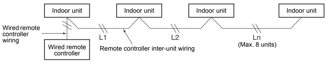
Wired remote controller wiring
This wiring is not required when using the supplied wireless remote controller.
- For wiring remote controllers a 2 core non polarity wire must be used.
| Wired remote controller wiring, remote controller inter-unit wiring | Wire size: 0.5mm² to 2.0mm² |
| | |
| Total wire length of wired remote controller wiring and remote controller inter-unit wiring = L + L1 + L2 + ... Ln | In case of wired type only | Up to 500m |
| In case of wireless type included | Up to 400m |
| Total wire length of wired remote controller inter-unit wiring = L1 + L2 + ... Ln | Up to 200m |

CAUTION
The remote controller wire (Communication line) and AC220-240V wires cannot be parallel to contact each other and cannot be stored in the same conduits. If doing so, a trouble may be caused on the control system due to noise, etc.
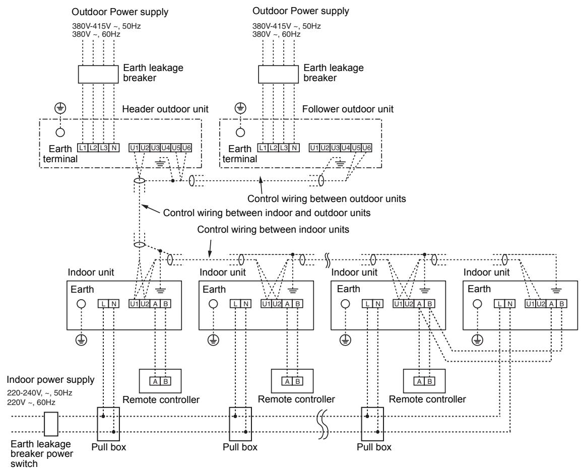
Control wiring between indoor and outdoor units
NOTE
An outdoor unit that is interconnected to the indoor units automatically becomes the header unit.
Wiring example
Address setup
Set up the addresses as per the Installation Manual supplied with the outdoor unit.
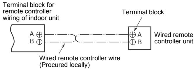
■ Wired remote controller wiring
- As the wired remote controller wire has non-polarity, there is no problem if connections to indoor unit terminal blocks A and B are reversed.
Wiring diagram
Wiring Connection
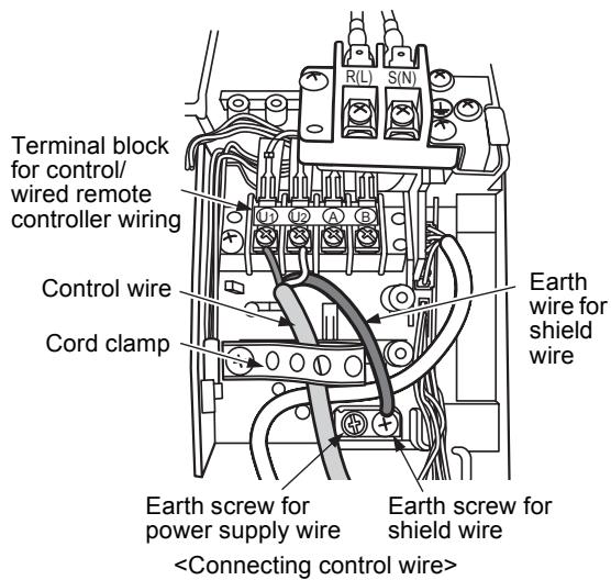
How to connect the power supply wiring and control wiring
The power supply wire and the control wire can be connected without removing the front panel.
REQUIREMENT
Connect the power supply wire after connecting the control wire for this model.
- Remove the air inlet grille. Open the air inlet grille upward and pull it toward you.
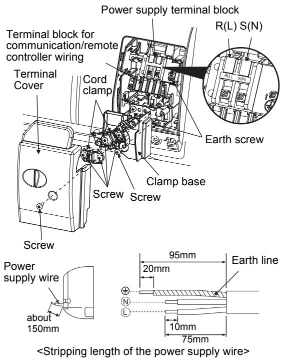
- Remove the terminal cover and the clamp base.
- Insert the power supply wire and control wire (according to the local rule) into the pipe hole on the wall.
- Take the power supply wire out of the cable slot on the rear panel so that it protrudes about 150mm from the front.
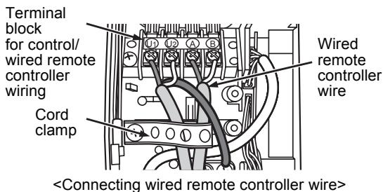
- Insert the control wire fully into the control/ wired remote controller terminal block _1 _2 A, B and secure it tightly with screws.
- Clamp the control wire with the cord clamp.
- Install the clamp base with a screw.
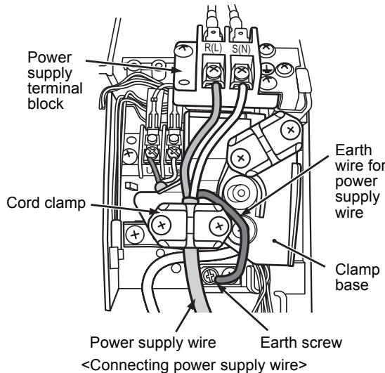
- Insert the power supply wire fully into the terminal block and secure it tightly with screws. Tightening torque: 1.2 N·m (0.12 kgf·m) Secure the earth line with the earth screw.
- Clamp the power supply wire with the cord clamp.
- Attach the terminal cover and the air inlet grille to the indoor unit.

CAUTION
- Be sure to refer to the wiring diagram attached inside the front panel.
- Check local electrical cords and also any specific wiring instructions and limitations.
- Do not catch the control wire when installing the clamp base.
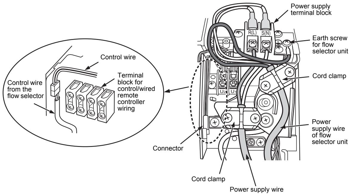
Wiring connection for flow selector unit
How to connect the wiring of flow selector unit
Connect the power supply wire and the communication wire supplied with the flow selector unit to the indoor unit.
- Remove the air inlet grille.
Open the air inlet grille upward and pull it toward you.
- Remove the four screws securing the front panel.
- Slightly open the lower part of the front panel, and then pull the upper part of the front panel toward you to remove it from the rear plate.
- Remove the terminal cover and the clamp base.
- Insert the control wire fully into the control/wired remote controller terminal block and secure it tightly with screws.
- Connect the control wire connector of the flow selector unit to the lead with a connector to the left of the control/wired remote controller terminal block.
- Clamp the control wire and the control wire of the flow selector unit with the cord clamp.
- Install the clamp base with a screw.
- Insert the power supply wire fully into the terminal block and secure it tightly with screws.
Tightening torque: 1.2N· m (0.12 kgf·m)
Secure the earth line with the earth screw.
10.Clamp the power supply wire with the cord clamp.
11.Insert the power supply wire fasten terminal of the flow selector unit into the power supply terminal.
Secure the earth line with the earth screw.
12.Clamp the power supply wire of the flow selector unit tight with the cord clamp.
13. Attach the terminal cover, the front panel and the air inlet grille to the indoor unit.

CAUTION
Confirm that every wires are stored in the electric parts box without getting caught before attaching the terminal cover.
11 APPLICABLE CONTROLS
A wired remote controller is necessary for this function. This function cannot be operate with a wireless remote controller.
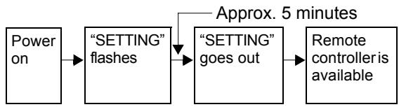
REQUIREMENT
- When you use this air conditioner for the first time, it takes approx. 5 minutes until the remote controller becomes available after power-on. This is normal.
It takes approx. 5 minutes until the remote controller becomes available.
It takes approx. 1 minute until the remote controller becomes available.

- Normal settings were made when the indoor unit was shipped from factory. Change the indoor unit settings as required.
-
Use the wired remote controller to change the settings.
-
The settings cannot be changed using the wireless remote controller, sub remote controller, or remote-controller less system (for central remote controller only). Therefore, install the wired remote controller to change the settings.
Changing of settings of for applicable controls
Basic procedure for changing settings
Change the settings while the air conditioner is not working.
(Be sure to stop the air conditioner before making settings.)
The display content for setting differs from that on the former types of remote controller (RBC-
AMT21E/AMT31E). (The number of CODE No. has increased.)
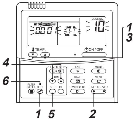
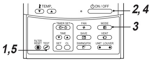
Procedure 1
Push TEST button and "TEMP." button simultaneously for at least 4 seconds.
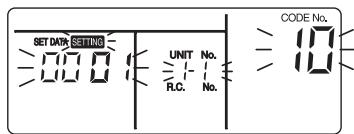
After a while, the display flashes as shown in the figure.
Confirm that the CODE No. is [10].
- If the CODE No. is not [10], push TEST button to erase the display content, and repeat the procedure from the beginning. (No operation of the remote controller is accepted for a while after TEST button is pushed.) (While air conditioners are operated under the group control, "ALL" is displayed first. When UNIT LOUVER is pushed, the indoor unit number displayed following "ALL" is the header unit.)
(*Display content varies with the indoor unit model.)
Procedure 2
Each time you push UNIT LOUVER button, indoor unit numbers in the control group change cyclically. Select the indoor unit you want to change settings for.
The fan of the selected unit runs and the louvers start swinging. You can confirm the indoor unit for which you want to change settings.
Procedure 3
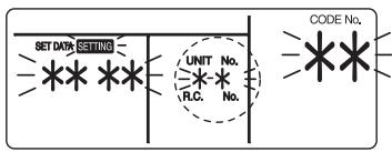
Using "TEMP." / buttons, specify CODE No.[**].
Procedure 4
Using timer "TIME" 一 / 一 buttons, select SET DATA [ ****].
Procedure 5
Push SET button. When the display changes from flashing to lit, the setup is completed.
- To change settings of another indoor unit, repeat from Procedure 2.
- To change other settings of the selected indoor unit, repeat from Procedure 3.
Use SET button to clear the settings.
To make settings after button was pushed, repeat from Procedure 2.
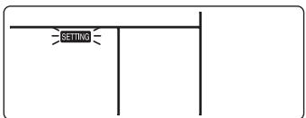
Procedure 6
When settings have been completed, push TEST button to determine the settings.
When TEST button is pushed, "SETTING" flashes and then the display content disappears and the air conditioner enters the normal stop mode.
While "SETTING" is flashing, no operation of the remote controller is accepted.
Change of lighting time of filter sign
According to the installation condition, the lighting time of the filter sign (Notification of filter cleaning) can be changed.
Follow to the basic operation procedure
$$
(\mathbf {1} \rightarrow \mathbf {2} \rightarrow \mathbf {3} \rightarrow \mathbf {4} \rightarrow \mathbf {5} \rightarrow \mathbf {6}).
$$
- For the CODE No.. in Procedure 3, specify [01].
- For the [SET DATA] in Procedure 4, select the SET DATA of filter sign lighting time from the following table.
| SET DATA | Filter sign lighting time |
| 0000 | None |
| 0001 | 150H (Factory setting) |
| 0002 | 2500H |
| 0003 | 5000H |
| 0004 | 10000H |
To secure better effect of heating
When it is difficult to obtain satisfactory heating due to installation place of the indoor unit or structure of the room, the detection temperature of heating can be raised. Also use a circulator, etc. to circulate heat air near the ceiling.
Follow to the basic operation procedure
$$
(\mathbf {1} \rightarrow \mathbf {2} \rightarrow \mathbf {3} \rightarrow \mathbf {4} \rightarrow \mathbf {5} \rightarrow \mathbf {6}).
$$
- For the CODE No.. in Procedure 3, specify [06].
- For the SET DATA in Procedure 4, select the SET DATA of shift value of detection temperature to be set up from the table below.
| SET DATA | Detection temp shift value |
| 0000 | No shift |
| 0001 | +1°C |
| 0002 | +2°C |
| 0003 | +3°C (Factory setting) |
| 0004 | +4°C |
| 0005 | +5°C |
| 0006 | +6°C |
■ Adjustment of air direction
- Using the remote controller switch, change the up/down air direction by moving the horizontal louver.
- Adjust the right/left air direction by bending the vertical grille inside of the air outlet port with hands.
REQUIREMENT
Do not touch the horizontal louver directly with hands; otherwise a trouble may be caused.
For handling of the horizontal louver, refer to
"Owner's Manual" attached to the outdoor unit.
Group control
In a group control, a remote controller can control up to maximum 8 units.
- The wired remote controller only can control a group control. The wireless remote controller is unavailable for this control.
- For cabling procedure and cables of the individual line (Identical refrigerant line) system, refer to "Electric work" in this Manual.
- Cabling between indoor units in a group is performed in the following procedure. Connect the indoor units by connecting the remote controller inter-unit cables from the remote controller terminal blocks (A, B) of the indoor unit connected with a remote controller to the remote controller terminal blocks (A, B) of the other indoor unit. (Non-polarity)
- For address setup, refer to the Installation Manual attached to the outdoor unit.
NOTE
Net work adapter (Model TCB-PCNT20E) can not connect to this High Wall type air conditioner.
12 TEST RUN
A wired remote controller is necessary for this function. This function cannot be operate with a wireless remote controller.
Before test run
- Before turning on the power supply, carry out the following procedure.
1) Using 500V-megger, check that resistance of 1M or more exists between the terminal block of the power supply and the earth (grounding). If resistance of less than 1M is detected, do not run the unit.
2) Check the valve of the outdoor unit being opened fully.
- To protect the compressor at activation time, leave power-ON for 12 hours or more be for operating.

WARNING
- Never press the electromagnetic contactor to forcibly perform a test run. (This is very dangerous because the protective device does not work.)
- Before starting a test run, be sure to set addresses following the installation manual supplied with the outdoor unit.
How to execute a test run
Using the wired remote controller, operate the unit as usual.
For the procedure of the operation, refer to the attached Owner's Manual.
A forced test run can be executed in the following procedure even if the operation stops by thermo.-OFF.
In order to prevent a serial operation, the forced test run is released after 60 minutes have passed and returns to the usual operation.

CAUTION
- Do not use the forced test run for cases other than the test run because it applies an excessive load to the devices.
In case of wired remote controller
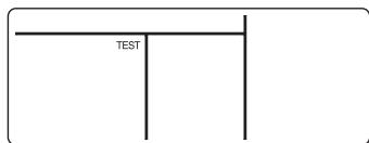
Procedure 1
Keep TEST button pushed for 4 seconds or more. [TEST] is displayed on the display part and the selection of mode in the test mode is permitted.
Procedure 2
Push ON/OFF button.
Procedure 3
MODE button, select the operation mode, [COOL] or [HEAT].
- Do not run the air conditioner in a mode other than [COOL] or [HEAT].
- The temperature controlling function does not work during test run.
- The detection of error is performed as usual.
Procedure 4
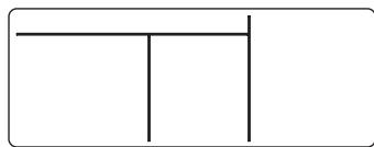
After the test run, push ON/OFF button to stop a test run.
(Display part is same as procedure 1.)
Procedure 5
Push TEST check button to cancel (release from) the test run mode.
([TEST] disappears on the display and the status returns to a normal.)
REQUIREMENT
- For the operation procedure, be sure to follow the Owner's Manual.
- Finish the forced cooling operation in a short time because it applies excessive strength to the air conditioner.
- A test operation of forced heating is unavailable. Perform a test operation by heating operation using the switches of the remote controller.
However heating operation may be not carried out according to the temperature conditions.
- Check wiring/piping of indoor and outdoor units
- When pushing ⑥ button for 10 seconds or more, "Pi!" sound is heard and the operation changes to a forced cooling operation. After approx. 3 minutes, a cooling operation starts forcibly. Check cool air starts blowing. If the operation does not start, check wiring again.
- To stop a test operation, push button once again (Approx. 1 second). The louver closes and the operation stops.
- Check transmission of remote controller
-
Push "START/STOP" button of the remote controller to check an operation can also start by the remote controller.
-
"Cooling" operation by the remote controller may be unavailable according to the temperature conditions.
Check wiring/piping of the indoor and outdoor units in forced cooling operation.
13 TROUBLE SHOOTING
A wired remote controller is necessary for this function. This function cannot be operate with a wireless remote controller.
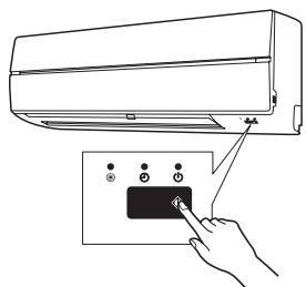
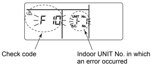
Confirmation and check
When a trouble occurred in the air conditioner, the check code and the indoor UNIT No. appear on the display part of the remote controller.
The check code is only displayed during the operation.
If the display disappears, operate the air conditioner according to the following "Confirmation of error history" for confirmation.
Confirmation of error history
When a trouble occurred on the air conditioner, the trouble history can be confirmed with the following procedure. (The trouble history is stored in memory up to 4 troubles.)
The history can be confirmed from both operating status and stop status.
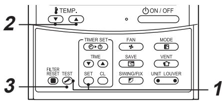
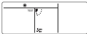
Procedure 1
When pushing SET and TEST buttons at the same time for 4 seconds or more, the following display appears.
If [Service check] is displayed, the mode enters in the trouble history mode.
- [01: Order of trouble history] is displayed in CODE No. window.
- [Check code] is displayed in CHECK window.
- [Indoor unit address in which an error occurred] is displayed in UNIT No.

Procedure 2
Every pushing of "TEMP." button used to set temperature, the trouble history stored in memory is displayed in order.
The numbers in CODE No. indicate CODE No. [01] (latest) [04] (oldest).
REQUIREMENT
Do not push button because all the trouble history of the indoor unit will be deleted.
Procedure 3
After confirmation, push TEST button to return to the usual display.
Check method
On the remote controller (Wired remote controller, Central control remote controller) and the interface P.C. board of the outdoor unit (I/F), a check display LCD (Remote controller) or 7-segment display (on the outdoor interface P.C. board) to display the operation is provided. Therefore the operation status can be known. Using this self-diagnosis function, a trouble or position with error of the air conditioner can be found as shown in the table below.
Check code list
The following list shows each check code. Find the check contents from the list according to part to be checked.
- In case of check from indoor remote controller: See "Wired remote controller display" in the list.
- In case of check from outdoor unit: See "Outdoor 7-segment display" in the list.
- In case of check from indoor unit with wireless remote controller: See "Sensor block display of receiving unit" in the list.
AI-NET: Artificial Intelligence.
IPDU: Intelligent Power Drive Unit
O: Lighting, O: Flashing, Goes off
ALT.: Flashing is alternately when there are two flashing LED.
SIM: Simultaneous flashing when there are two flashing LED.
| Check code | Wireless remote controller | Check code name | Judging device |
| Wired remote controller display | Outdoor 7-segment display | Sensor block display of receiving unit |
| Auxiliary code | OPERATION TIMER PRE.DEF. | Flash | |
| E01 | — | — | ☐ | ☐ | ☐ | Communication error between indoor and remote controller (Detected at remote controller side) | Remote controller |
| E02 | — | — | ☐ | ☐ | ☐ | Remote controller transmission error | Remote controller |
| E03 | — | — | ☐ | ☐ | ☐ | Communication error between indoor and remote controller (Detected at indoor side) | Indoor |
| E04 | — | — | ☐ | ☐ | ☐ | Communication circuit error between indoor/outdoor (Detected at indoor side) | Indoor |
| E06 | E06 | No. of indoor units in which sensor has been normally received | ☐ | ☐ | ☐ | Decrease of No. of indoor units | I/F |
| — | E07 | — | ☐ | ☐ | ☐ | Communication circuit error between indoor/outdoor (Detected at outdoor side) | I/F |
| E08 | E08 | Duplicated indoor addresses | ☐ | ☐ | ☐ | Duplicated indoor addresses | Indoor / I/F |
| E09 | — | — | ☐ | ☐ | ☐ | Duplicated main remote controllers | Remote controller |
| E10 | — | — | ☐ | ☐ | ☐ | Communication error between indoor MCU | Indoor |
| E12 | E12 | 01: Indoor/Outdoor communication
02: Communication between outdoor units | ☐ | ☐ | ☐ | Automatic address start error | I/F |
| E15 | E15 | — | ☐ | ☐ | ☐ | Indoor is nothing during automatic addressing | I/F |
| E16 | E16 | 00: Capacity over
01 ~:No. of connected units | ☐ | ☐ | ☐ | Capacity over / No. of connected indoor units | I/F |
| E18 | — | — | ☐ | ☐ | ☐ | Communication error between indoor units | Indoor |
| E19 | E19 | 00: Header is nothing
02: Two or more header units | ☐ | ☐ | ☐ | Outdoor header units quantity error | I/F |
| E20 | E20 | 01: Outdoor of other line connected
02: Indoor of other line connected | ☐ | ☐ | ☐ | Other line connected during automatic address | I/F |
| E23 | E23 | — | ● | ● | ○ | | Sending error in communication between outdoor units | I/F |
| E25 | E25 | — | ● | ● | ○ | | Duplicated follower outdoor addresses | I/F |
| E26 | E26 | No. of outdoor units which received signal normally | ● | ● | ○ | | Decrease of No. of connected outdoor units | I/F |
| E28 | E28 | Detected outdoor unit number | ● | ● | ○ | | Follower outdoor unit error | I/F |
| E31 | E31 | 01: IPDU1 error02: IPDU2 error03: IPDU1, 2 error04: Fan IPDU error05: IPDU + Fan IPDU error06: IPDU2 + Fan IPDU error07: All IPDU error | ● | ● | ○ | | IPDU communication error | I/F |
| F01 | — | — | ○ | ○ | ● | ALT | Indoor TCJ sensor error | Indoor |
| F02 | — | — | ○ | ○ | ● | ALT | Indoor TC2 sensor error | Indoor |
| F03 | — | — | ○ | ○ | ● | ALT | Indoor TC1 sensor error | Indoor |
| F04 | F04 | — | ○ | ○ | ○ | ALT | TD1 sensor error | I/F |
| F05 | F05 | — | ○ | ○ | ○ | ALT | TD2 sensor error | I/F |
| F06 | F06 | — | ○ | ○ | ○ | ALT | TE1 sensor error | I/F |
| F07 | F07 | — | ○ | ○ | ○ | ALT | TL sensor error | I/F |
| F08 | F08 | — | ○ | ○ | ○ | ALT | TO sensor error | I/F |
| F10 | — | — | ○ | ○ | ● | ALT | Indoor TA sensor error | Indoor |
| F12 | F12 | — | ○ | ○ | ○ | ALT | TS1 sensor error | I/F |
| F13 | F13 | 01: Comp. 1 side02: Comp. 2 side | ○ | ○ | ○ | ALT | TH sensor error | IPDU |
| F15 | F15 | — | ○ | ○ | ○ | ALT | Outdoor temp. sensor miscabling (TE, TL) | I/F |
| F16 | F16 | — | ○ | ○ | ○ | ALT | Outdoor pressure sensor miscabling (Pd, Ps) | I/F |
| F23 | F23 | — | ○ | ○ | ○ | ALT | Ps sensor error | I/F |
| F24 | F24 | — | ○ | ○ | ○ | ALT | Pd sensor error | I/F |
| F29 | — | — | ○ | ○ | ● | SIM | Indoor other error | Indoor |
| F31 | F31 | — | ○ | ○ | ○ | SIM | Indoor EEPROM error | I/F |
| H01 | H01 | 01: Comp. 1 side02: Comp. 2 side | ● | ○ | ● | | Compressor break down | IPDU |
| H02 | H02 | 01: Comp. 1 side02: Comp. 2 side | ● | ○ | ● | | Magnet switch errorOvercurrent relay operationCompressor trouble (lock) | MG-SWOvercurrent relayIPDU |
| H03 | H03 | 01: Comp. 1 side02: Comp. 2 side | ● | ○ | ● | | Current detect circuit system error | IPDU |
| H04 | H04 | — | ● | ○ | ● | | Comp 1 case thermo operation | I/F |
| H06 | H06 | — | ● | ○ | ● | | Low pressure protective operation | I/F |
| H07 | H07 | — | ● | ○ | ● | | Oil level down detective protection | I/F |
| H08 | H08 | 01: TK1 sensor error02: TK2 sensor error03: TK3 sensor error04: TK4 sensor error | ● | ○ | ● | | Oil level detective temp sensor error | I/F |
| H14 | H14 | — | ● | ○ | ● | | Comp 2 case thermo operation | I/F |
| H16 | H16 | 01: TK1 oil circuit system error02: TK2 oil circuit system error03: TK3 oil circuit system error04: TK4 oil circuit system error | ● | ○ | ● | | Oil level detective circuit errorMagnet switch errorOvercurrent relay operation | I/MG-SWOvercurrent relay |
| L03 | — | — | ○ | ● | ○ | SIM | Indoor centre unit duplicated | Indoor |
| L04 | L04 | — | ○ | ○ | ○ | SIM | Outdoor line address duplicated | I/F |
| L05 | — | — | ○ | ● | ○ | SIM | Duplicated indoor units with priority(Displayed in indoor unit with priority) | I/F |
| L06 | L06 | No. of indoor units with priority | ○ | ● | ○ | SIM | Duplicated indoor units with priority(Displayed in unit other than indoor unit with priority) | I/F |
| L07 | — | — | ○ | ● | ○ | SIM | Group line in individual indoor unit | Indoor |
| L08 | L08 | — | ○ | ● | ○ | SIM | Indoor group/Address unset | Indoor, I/F |
| L09 | — | — | ☐ ☐ ☐ | SIM | Indoor capacity unset | Indoor |
| L10 | L10 | — | ☐ ☐ ☐ | SIM | Outdoor capacity unset | I/F |
| L20 | — | — | ☐ ☐ ☐ | SIM | Duplicated central control addresses | AI-NET, Indoor |
| L28 | L28 | — | ☐ ☐ ☐ | SIM | Over No. of connected outdoor units | I/F |
| L29 | L29 | 01: IPDU1 error02: IPDU2 error03: IPDU3 error04: Fan IPDU error05: IPDU1 + Fan IPDU error06: IPDU2 + Fan IPDU error07: All IPDU error | ☐ ☐ ☐ | SIM | No. of IPDU error | I/F |
| L30 | L30 | Detected indoor address | ☐ ☐ ☐ | SIM | Indoor outside interlock | Indoor |
| — | L31 | — | — | | Extended I/C error | I/F |
| P01 | — | — | ☐ ☐ ☐ | ALT | Indoor fan motor error | Indoor |
| P03 | P03 | — | ☐ ☐ ☐ | ALT | Discharge temp. TD1 error | I/F |
| P04 | P04 | 01: Comp. 1 side02: Comp. 2 side | ☐ ☐ ☐ | ALT | High-pressure SW system operation | IPDU |
| P05 | P05 | 01: Phase-missing detection02: Phase error | ☐ ☐ ☐ | ALT | Phase-missing detection /Phase error | I/F |
| P07 | P07 | 01: Comp. 1 side02: Comp. 2 side | ☐ ☐ ☐ | ALT | Heat sink overheat error | IPDU, I/F |
| P10 | P10 | Detected indoor address | ☐ ☐ ☐ | ALT | Indoor overflow error | Indoor |
| P12 | — | — | ☐ ☐ ☐ | ALT | Indoor fan motor error | Indoor |
| P13 | P13 | — | ☐ ☐ ☐ | ALT | Outdoor liquid back detection error | I/F |
| P15 | P15 | 01: TS condition02: TD condition | ☐ ☐ ☐ | ALT | Gas leak detection | I/F |
| P17 | P17 | — | ☐ ☐ ☐ | ALT | Discharge temp. TD2 error | I/F |
| P19 | P19 | Detected outdoor unit number | ☐ ☐ ☐ | ALT | 4-way valve inverse error | I/F |
| P20 | P20 | — | ☐ ☐ ☐ | ALT | High-pressure protective operation | I/F |
| P22 | P22 | 0_____:IGBT short1_____:Fan motor positiondetective circuit error3_____:Fan motor troubleC_____:TH sensor temp. error(Heat sink overheat)D_____:TH sensor errorE_____:Vdc output error | ☐ ☐ ☐ | ALT | Outdoor fan IPDU error | IPDU |
| P26 | P26 | 01: Comp. 1 side02: Comp. 2 side | ☐ ☐ ☐ | ALT | G-TR short protection error | IPDU |
| P29 | P29 | 01: Comp. 1 side02: Comp. 2 side | ☐ ☐ ☐ | ALT | Comp position detective circuit systemerror | IPDU |
| P31 | P31 | — | ☐ ☐ ☐ | ALT | Other indoor unit error(Group terminal unit error) | Indoor |
| — | — | — | By alarm device ALT | | Error in indoor group | AI-NET |
Error detected by TCC-LINK central control device
| Check code | Wireless remote controller | Check code name | Judging device |
| Central control device indication | Outdoor 7-segment display | Sensor block display of receiving unit |
| Auxiliary code | OPERATION TIMER PRE.DEF. | Flash |
| C05 | — | — | — | Sending error in TCC-LINK central control device | TCC-LINK |
| C06 | — | — | — | Receiving error in TCC-LINK central control device | TCC-LINK |
| C12 | — | — | — | Batch alarm of general-purpose equipment control interface | General-purpose equipment I/F |
| P30 | Differs according to error contents of unit with occurrence of alarm | Group control branching unit error | TCC-LINK |
| — | — | (L20 is displayed.) | Duplicated central control addresses |
TCC-LINK: TOSHIBA Carrier Communication Link.
MEMO
TCC-LINK: TOSHIBA Carrier Communication Link.
MEMO
MEMO
请在安装空调之前仔细阅读本安装手册。
Check of Concentration Limit
The room in which the air conditioner is to be installed requires a design that in the event of refrigerant gas leaking out, its concentration will not exceed a set limit.
The refrigerant R410A which is used in the air conditioner is safe, without the toxicity or combustibility of ammonia, and is not restricted by laws to be imposed which protect the ozone layer. However, since it contains more than air, it poses the risk of suffocation if its concentration should rise excessively. Suffocation from leakage of R410A is almost non-existent. With the recent increase in the number of high concentration buildings, however, the installation of multi air conditioner systems is on the increase because of the need for effective use of floor space, individual control, energy conservation by curtailing heat and carrying power etc. Most importantly, the multi air conditioner system is able to replenish a large amount of refrigerant compared with conventional individual air conditioners. If a single unit of the multi conditioner system is to be installed in a small room, select a suitable model and installation procedure so that if the refrigerant accidentally leaks out, its concentration does not reach the limit (and in the event of an emergency, measures can be made before injury can occur).
In a room where the concentration may exceed the limit, create an opening with adjacent rooms, or install mechanical ventilation combined with a gas leak detection device.
The concentration is as given below.
Total amount of refrigerant (kg)
Min. volume of the indoor unit installed room (^3) ≤ Concentration limit (kg/m)
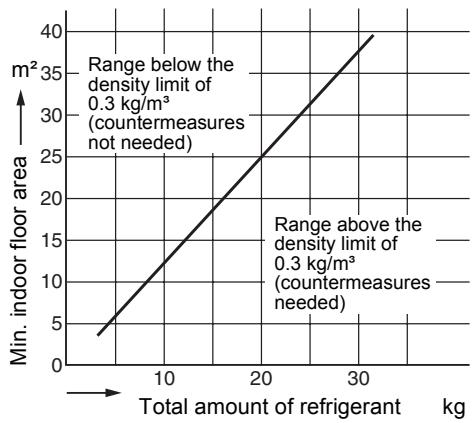
The concentration limit of R410A which is used in multi air conditioners is 0.3kg / m^3
NOTE 1
If there are 2 or more refrigerating systems in a single refrigerating device, the amounts of refrigerant should be as charged in each independent device.
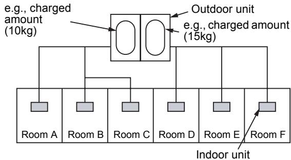
For the amount of charge in this example: The possible amount of leaked refrigerant gas in rooms A, B and C is 10kg The possible amount of leaked refrigerant gas in rooms D, E and F is 15kg
NOTE 2
The standards for minimum room volume are as follows.
(1) No partition (shaded portion)
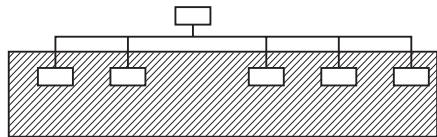
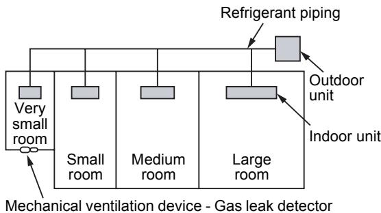
(2) When there is an effective opening with the adjacent room for ventilation of leaking refrigerant gas (opening without a door, or an opening 0.15% or larger than the respective floor spaces at the top or bottom of the door).

(3) If an indoor unit is installed in each partitioned room and the refrigerant piping is interconnected, the smallest room of course becomes the object. But when a mechanical ventilation is installed interlocked with a gas leakage detector in the smallest room where the density limit is exceeded, the volume of the next smallest room becomes the object.
NOTE 3
The minimum indoor floor area compared with the amount of refrigerant is roughly as follows: (When the ceiling is 2.7m high)
CONFIRMATION OF INDOOR UNIT SETUP
Prior to delivery to the customer, check the address and setup of the indoor unit, which has been installed in this time and fill the check sheet (Table below). Data of four units can be entered in this check sheet. Copy this sheet according to the No. of the indoor units. If the installed system is a group control system, use this sheet by entering each line system into each installation manual attached to the other indoor units.
REQUIREMENT
This check sheet is required for maintenance after installation. Be sure to fill this sheet and then pass this Installation Manual to the customers.
Indoor unit setup check sheet
| Indoor unit | Indoor unit | Indoor unit | Indoor unit |
| Room name | Room name | Room name | Room name |
| Model | Model | Model | Model |
| Check indoor unit address. (For check method, refer to Applicable controls in this sheet.)* In case of a single system, it is unnecessary to enter the indoor address. (CODE No.: Line [12], Indoor [13], Group [14], Central control [03]) |
| Line | Indoor | Group | Line | Indoor | Group | Line | Indoor | Group | Line | Indoor | Group |
| | | | | | | | | | | |
| Central control address | Central control address | Central control address | Central control address |
| | | |
| Various setup | Various setup | Various setup | Various setup |
| Have you changed high ceiling setup? If not, fill check mark [×] in [NO CHANGE], and fill check mark [×] in [ITEM] if changed, respectively. (For check method, refer to Applicable controls in this sheet.) * In case of replacement of short plugs on indoor microcomputer P.C. board, setup is automatically changed. |
| High ceiling setup(CODE No. [5d])□ NO CHANGE□ STANDARD[0000]□ HIGH CEILING 1[0001]□ HIGH CEILING 3[0003] | High ceiling setup(CODE No. [5d])□ NO CHANGE□ STANDARD[0000]□ HIGH CEILING 1[0001]□ HIGH CEILING 3[0003] | High ceiling setup(CODE No. [5d])□ NO CHANGE□ STANDARD[0000]□ HIGH CEILING 1[0001]□ HIGH CEILING 3[0003] | Hight ceiling setup(CODE No. [5d])□ NO CHANGE□ STANDARD[0000]□ HIGH CEILING 1[0001]□ HIGH CEILING 3[0003] |
| Have you changed lighting time of filter sign? If not, fill check mark [×] in [NO CHANGE], and fill check mark [×] in [ITEM] if changed, respectively.(For check method, refer to Applicable controls in this sheet.) |
| Filter sign lighting time(CODE No. [01])□ NO CHANGE□ NONE[0000]□ 150H[0001]□ 2500H[0002]□ 5000H[0003]□ 10000H[0004] | Filter sign lighting time(CODE No. [01])□ NO CHANGE□ NONE[0000]□ 150H[0001]□ 2500H[0002]□ 5000H[0003]□ 10000H[0004] | Filter sign lighting time(CODE No. [01])□ NO CHANGE□ NONE[0010]□ 150H[0001]□ 2500H[0002]□ 5000H[0003]□ 10000H[0004] | Filter sign lighting time(CODE No. [01])□ NO CHANGE□ NONE[0010]□ 150H[0001]□ 2500H [0002]□ 5000H[0003]□ 10000H[0004] |
| Have you changed detected temp. shift value? If not, fill check mark [×] in [NO CHANGE], and fill check mark [×] in [ITEM] if changed, respectively.(For check method, refer to Applicable control in this sheet.) |
| Detected temp. shift value setup(CODE No. [06])□ NO CHANGE□ NO SHIFT[0000]□ +1°C[0001]□ +2°C[0002]□ +3°C[0003]□ +4°C[0004]□ +5°C[0005]□ +6°C[0006] | Detected temp. shift value setup(CODE No. [06])□ NO CHANGE□ NO SHIFT[0000]□ +1°C[0001]□ +2°C[0002]□ +3°C[0003]□ +4°C[0004]□ +5°C[0005]□ +6°C[0006] | Detected temp. shift value setup(CCODE No. [06])□ NO CHANGE□ NO SHIFT[0000]□ +1°C[0001]□ +2°C[0002]□ +3°C[0003]□ +4°C[0004]□ +5°C[0005]□ +6°C[0006] | Detected temp. shift value setup(CODE No. [06])□ NO CHANGE☐ NO SHIFT[0000]□ +1°C[0001]□ +2°C[0002]□ +3°C[0003]□ +4°C[0004]□ +5°C[0005]□ +6°C[0006] |
| Incorporation of parts sold separately | Incorporation of parts sold separately | Incorporation of parts sold separately | Incorporation of parts sold separately |
| Have you incorporated the following parts sold separately? If incorporated, fill check mark [×] in each [ITEM].(When incorporating, the setup change is necessary in some cases. For setup change method, refer to Installation Manual attached to each part sold separately.) |
| Panel□ Standard panel | Panel□ Standard panel | Panel□ Standard panel | Panel□ Standard panel |
| Filter□ Super long life filter | Filter□ Super long life filter | Filter□ Super long life filter | Filter□ Super long life filter |
| □ Others()□ Others() | □ Others()□ Others() | □ Others()□ Others() | □ Others()□ Others() |