
MM-A0280HX - Microwaves TOSHIBA - Free user manual and instructions
Find the device manual for free MM-A0280HX TOSHIBA in PDF.
User questions about MM-A0280HX TOSHIBA
0 question about this device. Answer the ones you know or ask your own.
Ask a new question about this device
Download the instructions for your Microwaves in PDF format for free! Find your manual MM-A0280HX - TOSHIBA and take your electronic device back in hand. On this page are published all the documents necessary for the use of your device. MM-A0280HX by TOSHIBA.
USER MANUAL MM-A0280HX TOSHIBA
Installation Instructions
Air Conditioner - Multi Split Type System
GB
Instructions
Airconditioning - Multi-delig Type System

Contents
Introduction 4
Installation 9
Trial Operation 38
Troubleshooting 48
Environmental 64
F Passer à la page 65 pour dire le manuel d'installation en français.
Die deutsche Montageanleitung findsie auf Seite 127.
Por favor, vaya a la page 189 para seguir las instrucciones del manual de instalacion en lengua española.
Il manuale d'installazione italiano è a pagina 251.
NL Zie bladzijde 313 voor de Nederlandse Installatichandleiding.
Introduction
Contents
Precautions 5
Operating Conditions 6
Components 7
Metric/Imperial pipe conversion 7
Introduction
Precautions
Please read these instructions carefully before starting the installation.
This equipment should only be installed by suitably trained operatives.
In all cases ensure safe working practice: Observe precautions for persons in the vicinity of the works.
Ensure that all local, national and international regulations are satisfied.
Check that the electrical specifications of the unit meet the requirements of the site.
Carefully unpack the equipment, check for damage or shortages. Please report any damage immediately.
These units comply with EC Directive:
73/23/EEC (Low Voltage Directive) and 89/336/EEC (Electro Magnetic Compatibility).
Accordingly, they are designated for use in commercial and industrial environments.
Avoid installation in the following locations:
Where the water drainage may cause a nuisance or a hazard when frozen.
Where there is a danger of flammable gas leakage.
Where there are high concentrations of oil.
Where the atmosphere contains an excess of salt (as in coastal areas). Special maintenance is required to maintain product design life.
Where the airflow from the outdoor unit may cause annoyance.
Where the operating noise of the outdoor unit may cause annoyance.
Where the foundation is not strong enough to fully withstand the weight of the outdoor unit.
Where strong winds may blow against the air inlet of the outdoor unit.
Precautions for R407C Systems
R407C outdoor units use synthetic oils which are extremely hygroscopic. Therefore ensure that the refrigerant system is NEVER exposed to air or any form of moisture.
Mineral oils are unsuitable for use in these units and may lead to premature system failure.
Use only equipment which is suitable for use with R407C. Never use equipment which has been used with R22.
R407C should only be charged from the service cylinder in the liquid phase. It is advisable to use a gauge manifold set equipped with a liquid sight glass fitted in the centre (entry) port.
Introduction
Operating Conditions
| Outdoor Temperature | -5 ~ 43°C | Cooling |
| -15 ~ 21°C | Heating | |
| Room Temperature | 18 ~ 32°C | Cooling |
| 15 ~ 29°C | Heating | |
| Room Humidity | <80% | Cooling |
1. Allocation standard of Model name
OUTDOOR
MM-A0280HT
Maaannnnnne aannnnnne annnnnne
A - Outdoor
0280 - 28.0kW (10HP)
0224 - 22.4kW (8HP)
0160 - 16.0kW (6HP)
C - Cooling
H - Heating
T-Inverter
X - Fixed Speed
INDOOR
MM-TU056
Maaannnnnne aannnnnne
B Built-In Duct Type
C (CR) - Ceiling Type (IR Remote)
K (KR) - High Wall Type (IR Remote)
N - Carcase Type
S (SR) - Low Wall Type (IR Remote)
SB - Built-In Slim Duct Type
TU - 2 Way Cassette Type
U - 4 Way Cassette Type
028 - 2.8kW (1HP)
042-4.2kW(1.5HP)
056 - 5.6kW (2HP)
080 - 8.0kW (3HP)
112-11.2kW (4HP)
140-14.0kW(5HP)
2. Range of combined units
No. of combined units
: 1 to 5 units
Capacity range
: Equivalent to 14HP (0384kW type) to 46HP (1288kW)
3. Restriction for combination units
(1) The Inverter Unit should have the maximum capacity among all units in that combination.
(2) The 6HP fixed-speed unit is available only with the combination of 14HP and 22HP. (It cannot be used for any other combination.)
4. Rated conditions
Cooling
: Indoor air temperature 27°C DB/19°C WB
Outdoor air temperature 35^ C DB/25°C WB
Heating
: Indoor air temperature 21°C DB/15.5°C WB
Outdoor air temperature 7^ C DB/6°C WB
5. Mode Priority
This Outdoor Unit is set to operate with the Heating mode taking precedence. This precidence can be switched between Heat and Cool mode using the DIP switch 07 on the Outdoor Unit Interface PCB (MCC-1343-01) as follows:
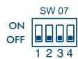
Heat Priority (factory set)
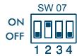
Cool Priority
Introduction
Components
1. Outdoor Unit
| Corresponding HP | Inverter unit | Fixed-speed unit | Appearance | |||
| 8HP | 10HP | 6HP | 8HP | 10HP | ||
| Model name | MM-A0224HT | MM-A0280HT | MM-A0160HX | MM-A0224HX | MM-A0280HX | |
| Cooling capacity (kW) | 22.4 | 28.0 | 16.0 | 22.4 | 28.0 | |
| Heating capacity (kW) | 25.0 | 31.5 | 18.0 | 25.0 | 31.5 | |
2. Outdoor Units (Combination of Outdoor Units)
| Corresponding HP | 8HP | 10HP | 14HP | 16HP | 18HP | 20HP | 22HP | 24HP | 26HP | 28HP | 30HP | 32HP | 34HP | 36HP | 38HP | 40HP | 42HP | 44HP | 46HP | |
| Combined Model MM-A~HT | 0224 | 0280 | 0384 | 0440 | 0504 | 0560 | 0608 | 0672 | 0728 | 0784 | 0840 | 0896 | 0952 | 1008 | 1064 | 1120 | 1176 | 1232 | 1288 | |
| Cooling capacity (kW) | 22.4 | 28.0 | 38.4 | 44.8 | 50.4 | 56.0 | 60.8 | 67.2 | 72.8 | 78.4 | 84.0 | 89.6 | 95.2 | 100.8 | 106.4 | 112.0 | 117.6 | 123.2 | 128.8 | |
| Combined outdoor units | Inverter unit | 8HP | 10HP | 8HP | 8HP | 10HP | 10HP | 8HP | 8HP | 10HP | 10HP | 10HP | 8HP | 10HP | 10HP | 10HP | 10HP | 10HP | 10HP | 10HP |
| Fixed-speed unit | — | — | 6HP | 8HP | 8HP | 10HP | 8HP | 8HP | 8HP | 10HP | 10HP | 8HP | 8HP | 10HP | 10HP | 10HP | 8HP | 10HP | 10HP | |
| — | — | — | — | — | — | 6HP | 8HP | 8HP | 8HP | 10HP | 8HP | 8HP | 8HP | 10HP | 10HP | 8HP | 8HP | 10HP | ||
| — | — | — | — | — | — | — | — | — | — | — | 8HP | 8HP | 8HP | 8HP | 10HP | 8HP | 8HP | 8HP | ||
| — | — | — | — | — | — | — | — | — | — | — | — | — | — | — | — | 8HP | 8HP | 8HP | ||
| No. of connectable indoor units | 13 | 16 | 16 | 18 | 18 | 20 | 22 | 24 | 26 | 28 | 30 | 32 | 34 | 36 | 38 | 40 | 40 | 40 | 40 | |
| Min. HP Connection | 4 | 5 | 7 | 8 | 9 | 10 | 11 | 12 | 13 | 14 | 15 | 16 | 17 | 18 | 19 | 20 | 21 | 22 | 23 | |
| Max. HP Connection | 10.8 | 13.5 | 18.9 | 21.6 | 24.3 | 27 | 29.7 | 32.4 | 35.1 | 37.8 | 40.5 | 43.2 | 45.9 | 48.6 | 51.3 | 54 | 56.7 | 59.4 | 62.1 | |
Metric/Imperial pipe conversion
| Diameter (mm) | 6.4 | 9.5 | 12.7 | 15.9 | 19.0 | 22.0 | 28.6 | 34.9 | 41.3 | 54.1 |
| Nominal Diameter (inch) | 1/4 | 3/8 | 1/2 | 5/8 | 3/4 | 7/8 | 1 1/8 | 1 3/8 | 1 5/8 | 2 1/8 |
Note: 1.0MPaG = 10.2kgf/cm^2G
Introduction
Components
- Indoor Unit
| Type | Appearance | Model name | Capacity code/HP | Cooling Capacity(kW) | Heating Capacity(kW) |
| 4 Way Cassette Type 'U' | MM-U056 | 2 | 5.6 | 6.4 | |
| MM-U080 | 3 | 8.0 | 9.6 | ||
| MM-U112 | 4 | 11.2 | 12.8 | ||
| MM-U140 | 5 | 14.0 | 15.8 | ||
| 2 Way Cassette Type 'TU' | MM-TU028 | 1 | 2.8 | 3.2 | |
| MM-TU042 | 1.5 | 4.2 | 4.8 | ||
| MM-TU056 | 2 | 5.6 | 6.4 | ||
| Built-In Slim Duct Type 'SB' | MM-SB028 | 1 | 2.8 | 3.2 | |
| Built-In Slim Duct, Type 'B' | MM-B056 | 2 | 5.6 | 6.4 | |
| MM-B080 | 3 | 8.0 | 9.6 | ||
| MM-B112 | 4 | 11.2 | 12.8 | ||
| MM-B140 | 5 | 14.0 | 15.8 | ||
| Ceiling Type 'C' | MM-C/CR042 | 1.5 | 4.2 | 4.8 | |
| MM-C/CR056 | 2 | 5.6 | 6.4 | ||
| MM-C/CR080 | 3 | 8.0 | 9.6 | ||
| MM-C/CR112 | 4 | 11.2 | 12.8 | ||
| MM-C/CR140 | 5 | 14.0 | 15.8 | ||
| High Wall Type 'K' | MM-K/KR042 | 1.5 | 4.2 | 4.8 | |
| MM-K/KR056 | 2 | 5.6 | 6.4 | ||
| MM-K/KR080 | 3 | 8.0 | 9.6 | ||
| Carcase Type 'N' | MM-N028 | 1 | 2.8 | 3.2 | |
| MM-N042 | 1.5 | 4.2 | 4.8 | ||
| MM-N056 | 2 | 5.6 | 6.4 | ||
| MM-N080 | 3 | 8.0 | 9.6 | ||
| Low Wall Type 'S' | MM-S/SR056 | 2 | 5.6 | 6.4 | |
| MM-S/SR080 | 3 | 8.0 | 9.6 |
Contents
Outdoor Unit
Transportation of the Outdoor Unit 10
Installation of Outdoor Unit 11
Dimensional Drawings Outdoor Unit 12
Dimensional Drawings Two Units Connected 13
Dimensional Drawings Three Units Connected 14
Dimensional Drawings Four Units Connected 15
Dimensional Drawings Five Units Connected 16
Multiple Installation on the Rooftop 17
Piping
Free Branching System 19
Connecting Refrigerant Pipes 20
Permissible Length/Height Separation of Refrigerant Piping . . . . . .21
Selection of Refrigerant Piping and Charge Requirement 22
Branch Headers/Branch Joints (Accessories) 24
Branch Header/T-shape Branch Joint 25
Connecting the Branching Kit/Y-shape Branching Joint 26
Heat Insulating the Branching Pipes/Branching Header 27
T-shape Branching Joint - to Connect Outdoor Units 29
Installation of Gas/Liquid Branching Pipes. 30
Airtight Test 31
Leak Position Check/Air Purge 32
Calculating the Additional Refrigerant Required 33
Additional Charge Amounts 34
Wiring
General/Wiring System Overview 35
Connecting Power Source Cable/Control Cable 36
Control Wiring Overview 37
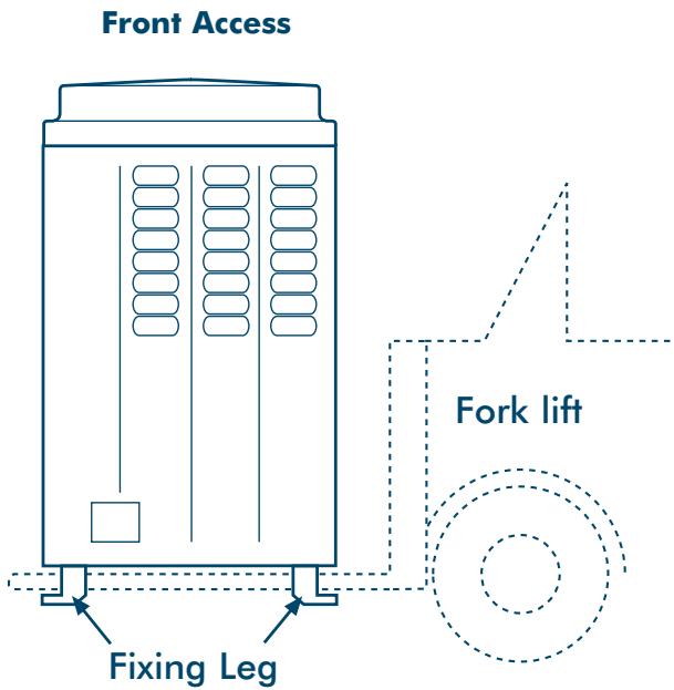
Transportation of the Outdoor Unit
Fork Lift
- Front Access - insert the forks into the slots on the fixing legs.
- Side Access - see diagram.
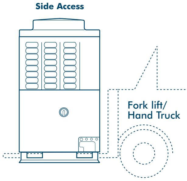
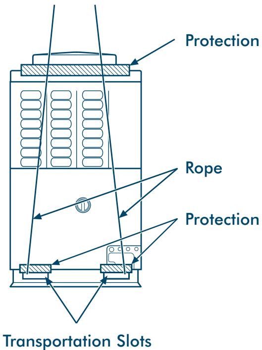
Crane
- Check the suitability of the lifting rope (see table).
- Secure lifting rope through transportation slot.
- Protect the unit where rope contact could scratch or deform it.
| Model | Weight |
| MM-A0280HT | 284.0kg |
| MM-A0224HT | 282.0kg |
| MM-A0280HX | 280.0kg |
| MM-A0224HX | 278.0kg |
| MM-A0160HX | 204.0kg |
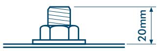
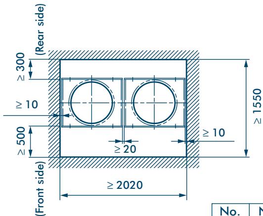
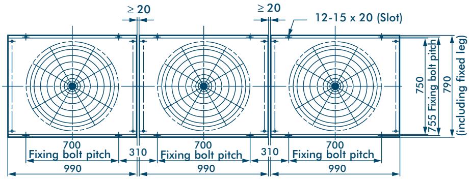
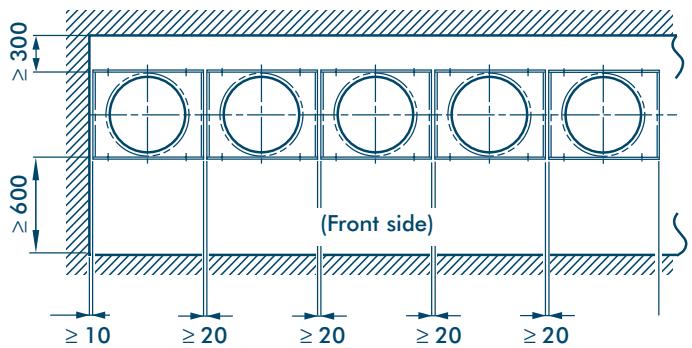
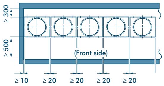
Installation of Outdoor Unit
- Align the outdoor units at intervals of 20mm or more.
Fix the outdoor units with M12 anchor bolts. (4 positions per unit.)
Anchor bolt with 20mm length is suitable.
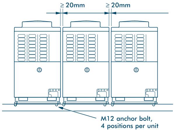
- Anchor bolt pitch is as shown in the following figure.
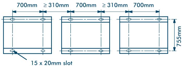
- However, the equivalent pipe length between the nearest outdoor unit and farthest outdoor unit of the refrigerating cycle system should not exceed 20m .
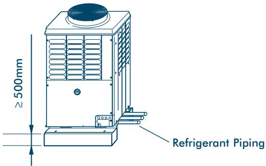
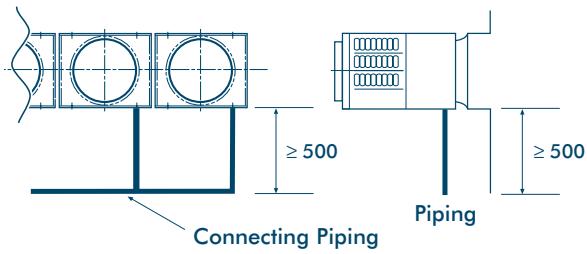
- When routing the refrigerant piping through the base, the fixing height of the base (two-divided foundations) must be 500m or more.
- Correct foundation mounts for supporting the Outdoor unit:
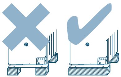
Note: The leading outdoor unit to be connected to the main refrigerant piping for the indoor units must be an inverter unit.
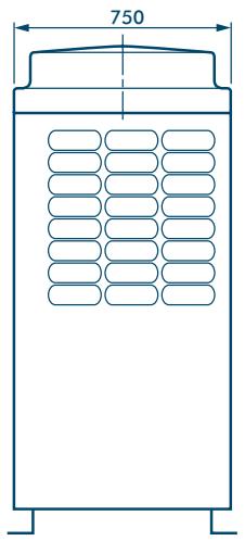
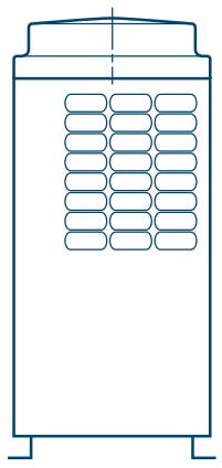
Dimensional Drawings
Outdoor Unit
Model Name:
MM-A0280HT, MM-A0224HT, MM-A0280HX, MM-A0224HX, MM-A0160HX
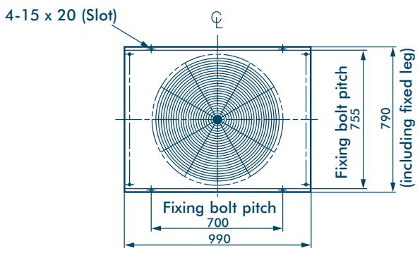
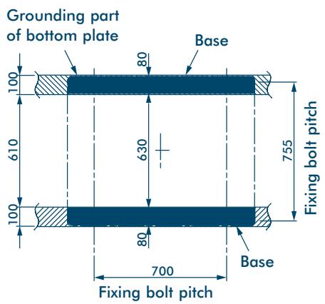
Base bolt position
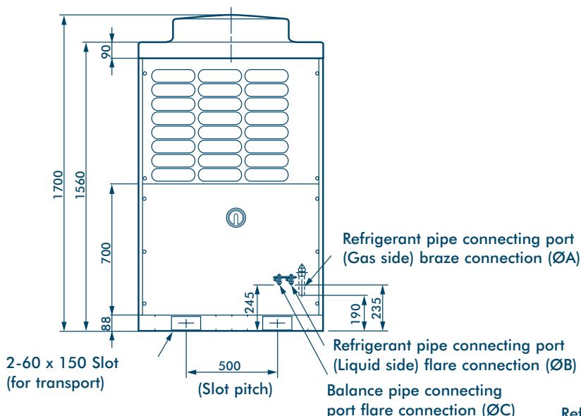
Note: All dimensions in (mm)
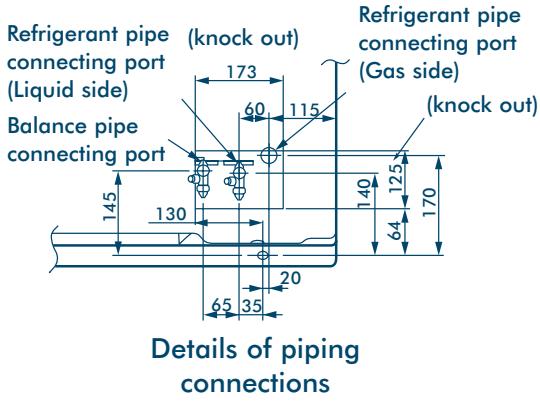
| Model | ØA mm | ØB mm | ØC mm |
| MM-A0280HT, MM-A0280HX | 28.6 | 12.7 | 9.52 |
| MM-A0224HT, MM-A0224HX | 22.2 | 12.7 | 9.52 |
| MM-A0160HX | 22.2 | 9.52 | 9.52 |
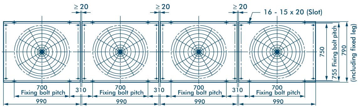
Dimensional Drawings
Two Units Connected
Model Name:
MM-A0384HT, MM-A0440HT, MM-A0504HT, MM-A0560HT
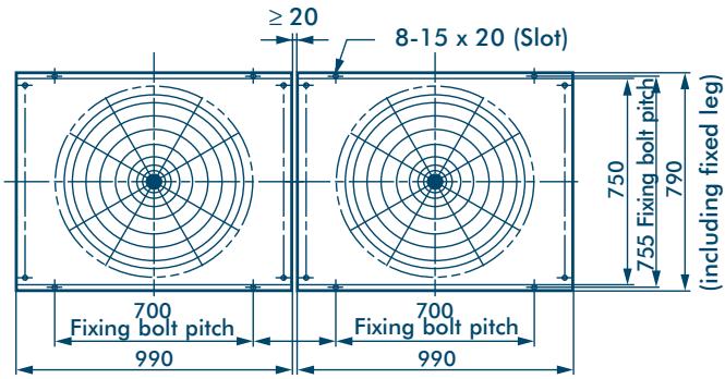
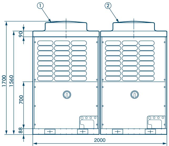
| No. | Name |
| ① | Outdoor Unit (Inverter type) |
| ② | Outdoor Unit (Fixed-speed type) |
Note: All dimensions in (mm)
Dimensional Drawings
Three Units Connected
Model Name:
MM-A0608HT, MM-A0672HT, MM-A0728HT, MM-A0784HT, MM-A0840HT
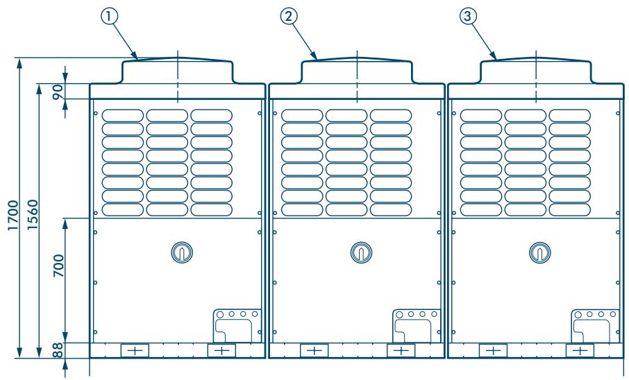
Note: All dimensions in (mm)
| No. | Name |
| ① | Outdoor Unit (Inverter type) |
| ② | Outdoor Unit (Fixed-speed type 1) |
| ③ | Outdoor Unit (Fixed-speed type 2) |
Dimensional Drawings
Four Units Connected
Model Name:
MM-A0896HT, MM-A0952HT, MM-A1008HT, MM-A1064HT, MM-A1120HT
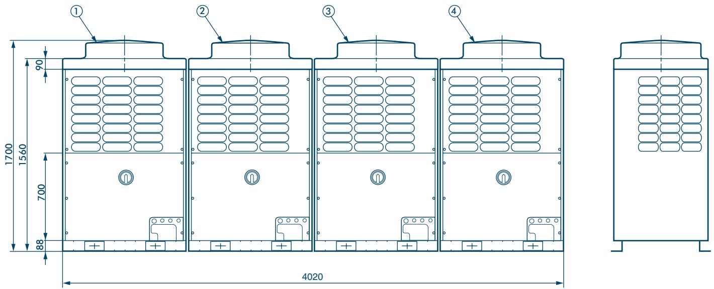
Note: All dimensions in (mm)
| No. | Name |
| ① | Outdoor Unit (Inverter type) |
| ② | Outdoor Unit (Fixed-speed type 1) |
| ③ | Outdoor Unit (Fixed-speed type 2) |
| ④ | Outdoor Unit (Fixed-speed type 3) |
Dimensional Drawings
Five Units Connected
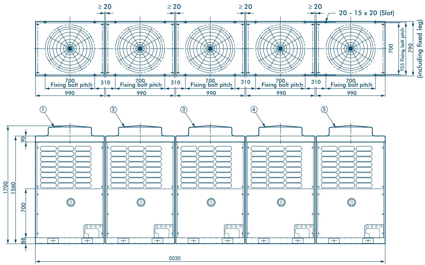
Model Name:
MM-A1176HT, MM-A1232HT, MM-A1288HT
Note: All dimensions in (mm)
| No. | Name |
| ① | Outdoor Unit (Inverter type) |
| ② | Outdoor Unit (Fixed-speed type 1) |
| ③ | Outdoor Unit (Fixed-speed type 2) |
| ④ | Outdoor Unit (Fixed-speed type 3) |
| ⑤ | Outdoor Unit (Fixed-speed type 4) |
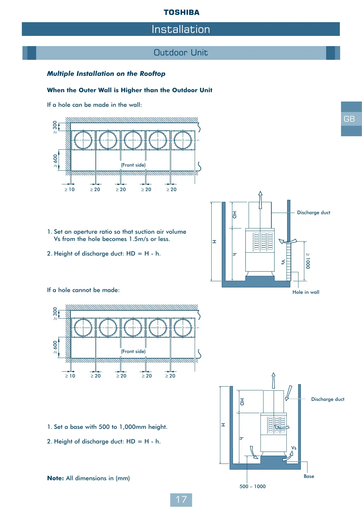
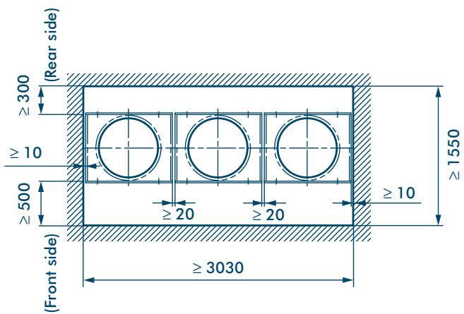
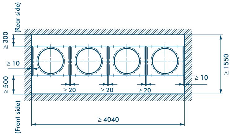
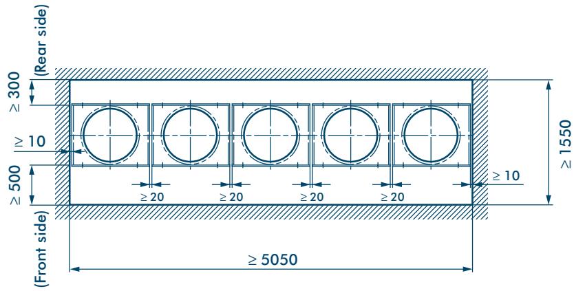
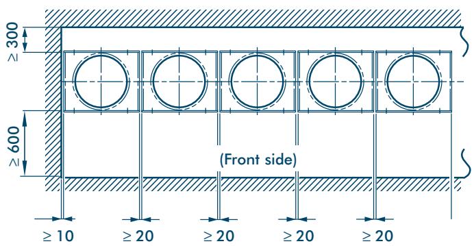
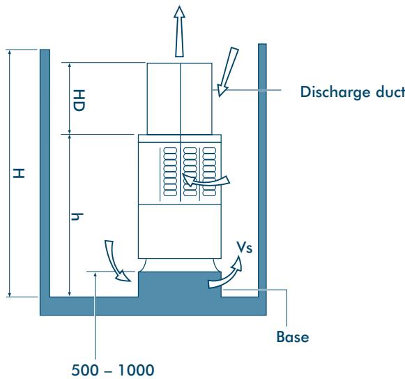
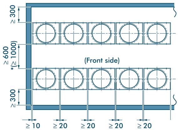
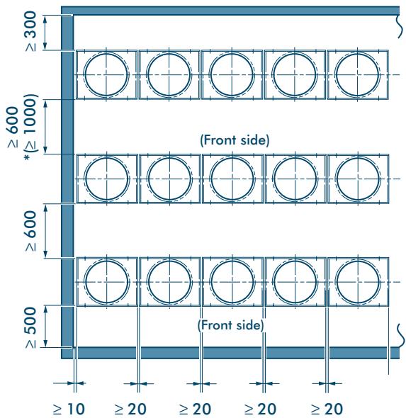
Multiple Installation on the Rooftop
When the Outer Wall is Higher than the Outdoor Unit
If a hole can be made in the wall:
- Set an aperture ratio so that suction air volume Vs from the hole becomes 1.5m / s or less.
- Height of discharge duct: HD = H - h
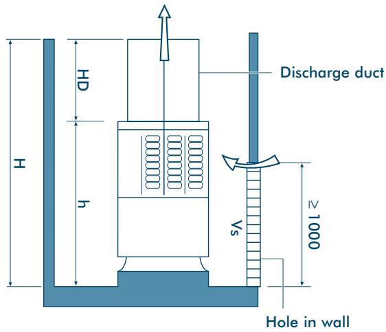
If a hole cannot be made:
- Set a base with 500 to 1,000mm height.
- Height of discharge duct: HD = H - h
Note: All dimensions in (mm)
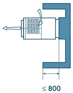
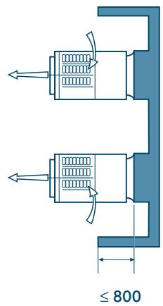
When the Outer Wall is Lower than the Outdoor Unit
1-line installation
2-parallel lines installation
3-parallel lines installation
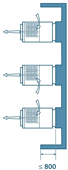
- When refrigerant piping is routed from the front of the unit, distance between Outdoor Unit and Connecting piping must be 500mm or more.
Note: All dimensions in (mm)
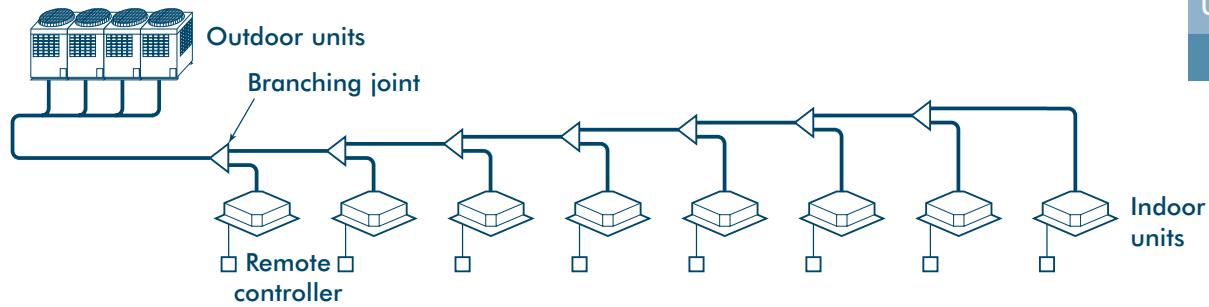
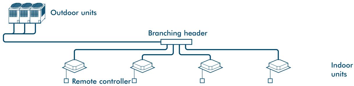
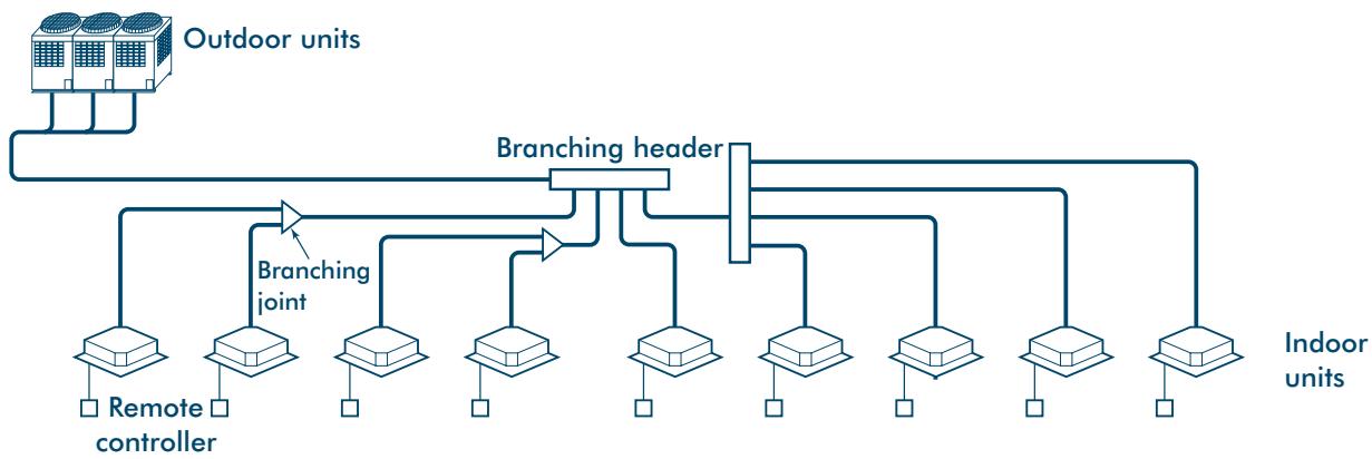
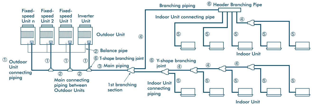
Free Branching System
The following five branching systems are available to increase the flexibility of refrigerant piping design.
Line branching system
2 Header branching system
3 Header branching system after line branching
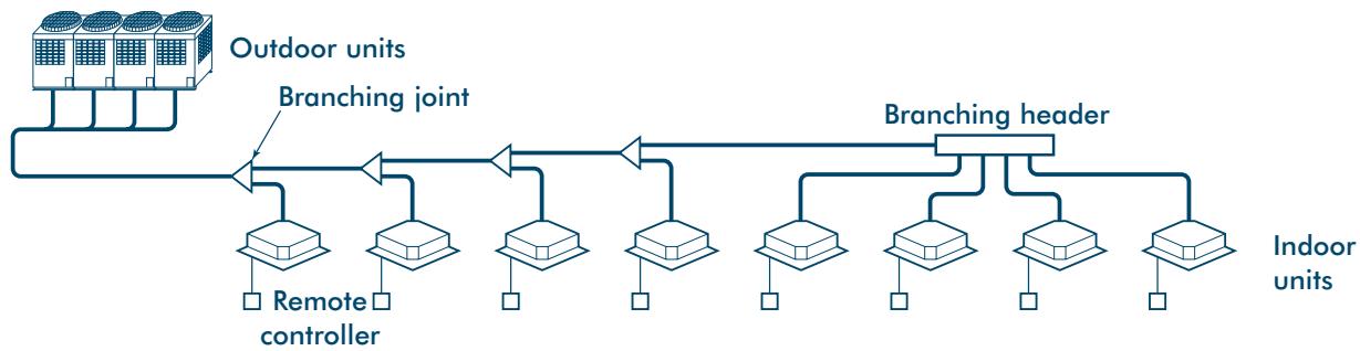
Line branching system after header branching
WARNING!
During installation – if the refrigerant gas leaks, ventilate the room. After installation – check for gas leakages.
If refrigerant gas comes into contact with fire – noxious gas may result!
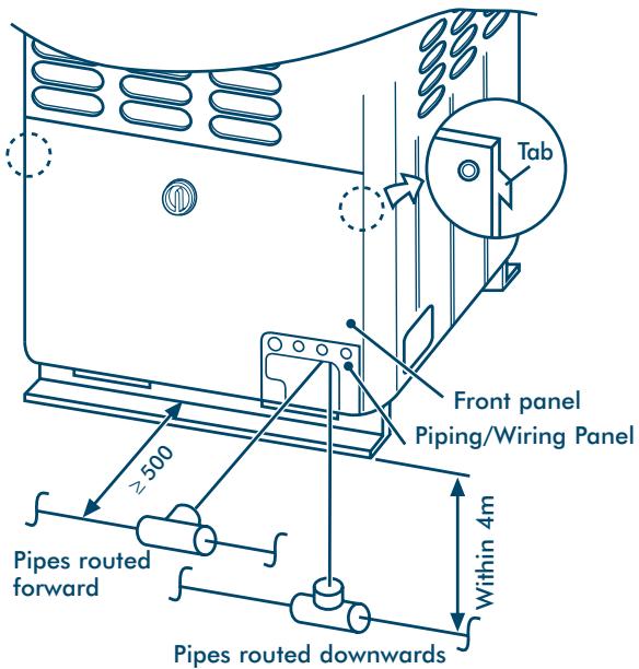
Connecting Refrigerant Pipes
- To access the refrigerant piping connections and electrical wiring terminals, remove the 7xM5 securing bolts in the front panel. To remove the panel, lift it up and away from its hanging tabs - See diagram.
- The refrigerant pipes can be routed forwards, downwards or sideways.
- If the pipes are routed forwards, make sure they exit through the Piping/Wiring Panel - (remove knock out section) and allow at least 500mm between the Outdoor Unit and the main pipe connecting it to the Indoor Unit. This is for servicing access. (Replacing the compressor, for example, requires a space of at least 500mm.)
- If the pipes are routed downwards, remove the knockout section in the baseplate of the Outdoor Unit. This will enable access. They can then be connected to the left or right, or the rear side. (Leading pipe of the balancing should be within 4m.)
Notes:
- When brazing, use nitrogen. This prevents internal oxidisation of the pipes.
- Always use clean new pipe, and ensure it is not contaminated by water or dust.
- Always use a double spanner on the flare nut - and tighten to the specified torque: (see table).
Note: All dimensions in (mm)
| Connecting pipe outer dia. (mm) | Tightening torque (Nm) | Re-tightening torque (Nm) |
| Ø6.4 | 11.8 (1.2kgf m) | 13.7 (1.4kgf m) |
| Ø9.5 | 24.5 (2.5kgf m) | 29.4 (3.0kgf m) |
| Ø12.7 | 49.0 (5.0kgf m) | 53.9 (5.5kgf m) |
| Ø15.9 | 78.4 (8.0kgf m) | 98.0 (10.0kgf m) |
| Ø19.0 | 98.0 (10.0kgf m) | 117.7 (12.0kgf m) |
Permissible Length/Height Separation of Refrigerant Piping
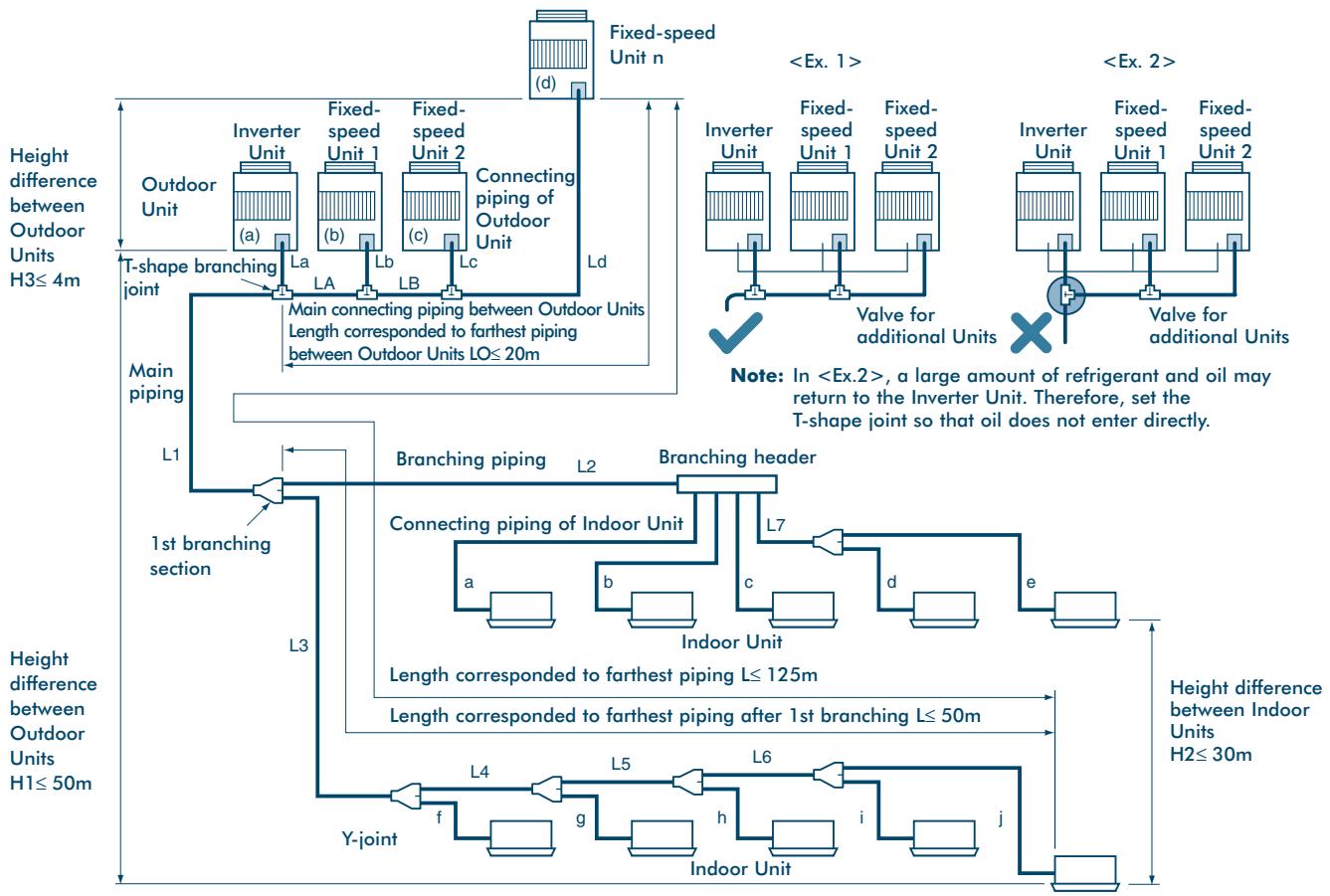
System Restrictions
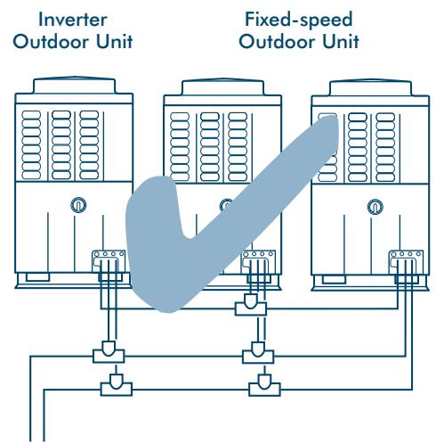
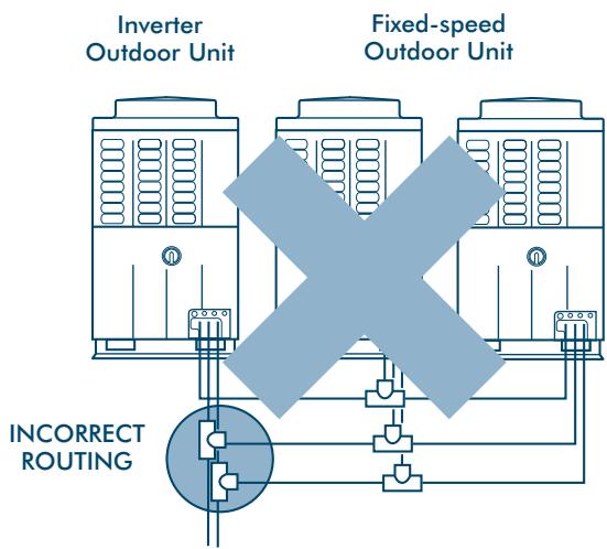
Notes: Combination of Outdoor Units: Inverter Unit + Fixed-speed Unit (0 to 4 units).
Combination of Fixed-speed Units without Inverter Unit is not permissible.
The Inverter Unit is the master Outdoor Unit and is directly connected to the indoor distribution pipe.
Install the Outdoor Units in order of capacity.
(Inverter Unit≥ Fixed-speed Unit 1 > Fixed-speed Unit 2 > Fixed-speed Unit n).
| Max. No. of combined outdoor units | 5 units | |
| Max. capacity of combined outdoor units | 128.8kW/46HP | |
| Max. No. of connected indoor units | 40 units | |
| Max. capacity of combined indoor units | H2≤ 15 | 135% |
| H2>15 | 105% | |
| Allowable value | Piping section | |||
| Piping length | Total extension of pipe (Liquid pipe, real length) | 250m | LA + LB + La + Lb + Lc + Ld + L1 + L2 + L3 + L4 + L5 + L6 + L7 + a + b + c + d + e + f + g + h + i + j | |
| Farthest piping length L (*) | Real length | 100m | LA + LB + Ld + L1 + L3 + L4 + L5 + L6 + j | |
| Equivalent length | 125m | |||
| Equivalent length of farthest piping from 1st branching Li (*) | 50m | L3 + L4 + L5 + L6 + j | ||
| Equivalent length of farthest piping between outdoor units LO (*) | 20m | LA + LB + Ld, LA + Lb, LA + LB + Lc | ||
| Max. equivalent length of outdoor unit connecting piping | 10m | Ld, La, Lb, Lc | ||
| Height difference | Height between indoor and outdoor units H1 | Upper outdoor unit | 50m | — |
| Lower outdoor unit | 30m | — | ||
| Height between indoor units H2 | 30m | — | ||
| Height between outdoor units H3 | 4m | — | ||
^*(d) is Outdoor Unit farthest from branching and (j) is Indoor Unit farthest from 1st branching.
Selection of Refrigerant Piping and Charge Requirement
Pipe Size of Outdoor Unit
| kW | HP | Model name | Gas side | Liquid side |
| 16.0 | 6 | MM-A0160HX | Ø22.2 | Ø9.5 |
| 22.4 | 8 | MM-A0224HT, MM-A0224HX | Ø22.2 | Ø12.7 |
| 28.0 | 10 | MM-A0280HT, MM-A0280HX | Ø28.6 | Ø12.7 |
2 Connecting Pipe Size Between Outdoor Units
| Total capacity code of outdoor units | Gas side | Liquid side | Balance pipe |
| Below 16 | Ø28.6 | Ø15.9 | Ø9.5 |
| 16 to Below 20 | Ø34.9 | Ø15.9 | Ø9.5 |
| 20 to Below 26 | Ø41.3 | Ø19.0 | Ø9.5 |
| 26 to Below 32 | Ø41.3 | Ø22.2 | Ø9.5 |
| 32 or more | Ø54.1 | Ø22.2 | Ø9.5 |
3 Size of Main Pipe
| Total capacity code of all outdoor units | Gas side | Liquid side |
| Below 10 | Ø22.2 | Ø12.7 |
| 10 to Below 14 | Ø28.6 | Ø12.7 |
| 14 to Below 20 | Ø34.9 | Ø15.9 |
| 20 to Below 26 | Ø41.3 | Ø19.0 |
| 26 to Below 32 | Ø41.3 | Ø22.2 |
| 32 or more | Ø54.1 | Ø22.2 |
4 Size Between Branching Sections
| Total capacity code of indoor units downstream (*1) | Gas side | Liquid side |
| Below 4.0 | Ø15.9 | Ø9.5 |
| 4.0 to Below 6.4 | Ø19.0 | Ø9.5 |
| 6.4 to Below 13.2 | Ø22.2 | Ø12.7 |
| 13.2 to Below 19.2 | Ø34.9 | Ø15.9 |
| 19.2 to Below 25.2 | Ø41.3 | Ø19.0 |
| 25.2 to Below 31.2 | Ø41.3 | Ø19.0 |
| 31.2 or more | Ø54.1 | Ø22.2 |
Piping
5 Piping of Indoor Unit
| Unit | Gas side (*4) | Liquid side |
| 028 type to 056 type | Ø12.7 | Ø 6.4 |
| 080 type | Ø15.9 | Ø 9.5 |
| 112 type to 140 type | Ø19.0 | Ø 9.5 |
i.e. MM-SB028 = Gas 12.7 , Liquid 6.4
6 Branching joints/headers
| Model name | Usage | Appearance | |||
| Y-shape branching joint | RBM-Y018 | Indoor unit capacity code (*1): Total below 6.4 | - | ||
| RBM-Y037 | Indoor unit capacity code (*1): Total 6.4 or more and below 13.2 (*2) | ||||
| RBM-Y071 | Indoor unit capacity code (*1): Total 13.2 or more and below 25.2 (*2) | ||||
| RBM-Y129 | Indoor unit capacity code (*1): Total 25.2 or more (*2) | ||||
| 4-branching header (*3) | RBM-H4037 | Indoor unit capacity code (*1): Total below 13.2 | Max. 4 branches | - | |
| RBM-H4071 | Indoor unit capacity code (*1): Total 13.2 or more and below 25.2 | ||||
| 8-branching header (*3) | RBM-H8037 | Indoor unit capacity code (*1): Total below 13.2 | Max. 8 branches | ||
| RBM-H8071 | Indoor unit capacity code (*1): Total 13.2 or more and below 25.2 | ||||
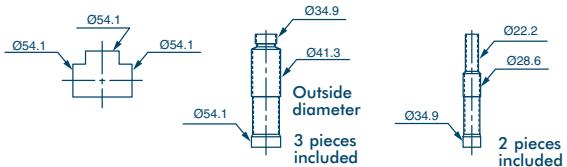
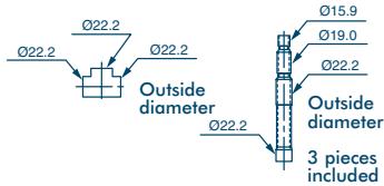
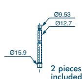
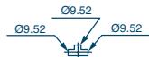
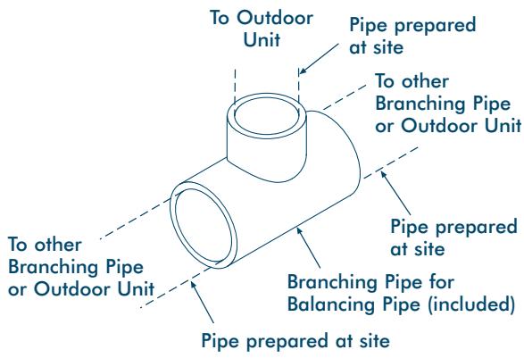
| T-shape branching joint (For connection of outdoor unit) | RBM-T129 | 1 set of 3 types of T-shape joint pipes as described below: The required quantity is arranged and they are combined at the site. | |||
| Connecting pipe | Corresponding dia. (mm) | Qty | |||
| Balancing pipe | Ø9.52 | 1 | |||
| Piping at liquid side | Ø12.7 to Ø22.2 | 1 | |||
| Piping at gas side | Ø22.2 to Ø54.1 | 1 | |||
7 Additional Refrigerant Amount
| Liquid pipe size | Additional refrigerant amount for liquid pipe 1m (kg) |
| Ø6.4 | 0.030 |
| Ø9.5 | 0.065 |
| Ø12.7 | 0.115 |
| Ø15.9 | 0.190 |
| Ø19.0 | 0.290 |
| Ø22.2 | 0.420 |
() Code is determined according to the capacity code of the Indoor Units connected. For details, refer to the Introduction section in this manual.
(^2) If the total capacity code value of Indoor Units exceeds that of Outdoor Units, apply the capacity code of Outdoor Units.
() When using a branch header, Indoor Units with a maximum of 6.0 capacity code in total can be connected to each branch.
(4) If the length of the gas pipe exceeds 30m from the 1st branching to an Indoor Unit, increase the Gas pipe section by 1 size, i.e. MM-U140 = Gas Ø22.2, Liquid Ø9.5.
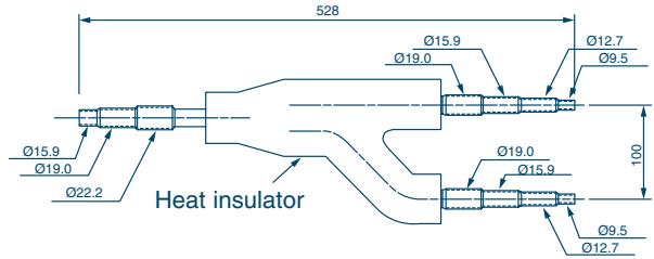
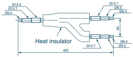
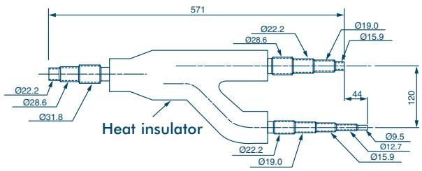
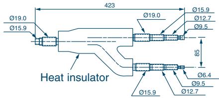
Branch Headers/Branch Joints (Accessories)
Y-shape Branch Joint
RBM-Y018
[Gas side]
[Liquid side]
RBM-Y037
[Gas side]
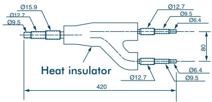
[Liquid side]
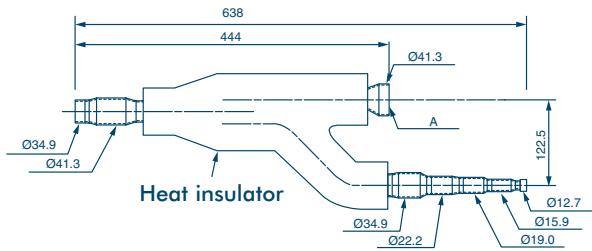
RBM-Y071
[Gas side]
[Liquid side]
RBM-Y129
[Gas side]
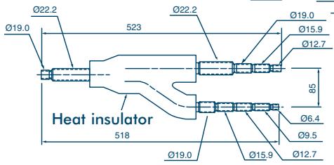
[Liquid side]
Note:
This additional connecting pipe is used if the gas pipe size is 041.3 or less. When brazing, the minimum insertion margin is 15mm .
Note: All dimensions in (mm)
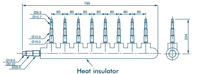
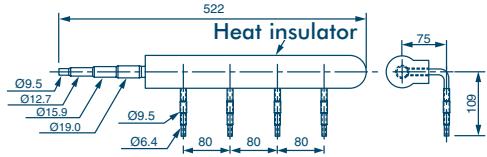
Branch Header
Note: Pipe dia. shown indicates dia. of pipe to be connected.
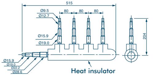
RBM-H4037
[Gas side]
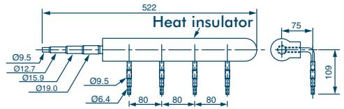
[Liquid side]
RBM-H8037
[Gas side]
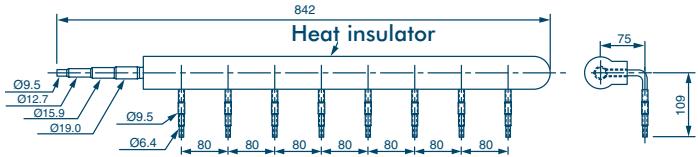
[Liquid side]
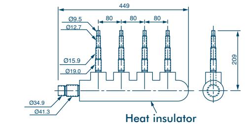
RBM-H4071
[Gas side]
[Liquid side]
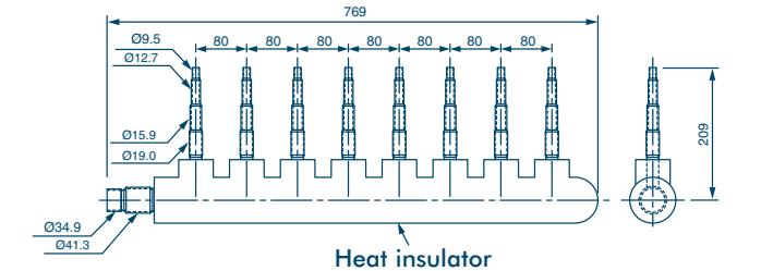
RBM-H8071
[Gas side]
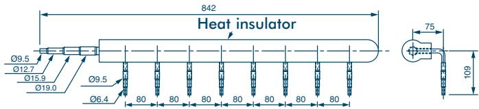
[Liquid side]
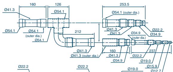
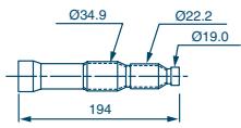
T-shape Branch Joint
RBM-T129
[Gas side]
[Liquid side]
[Balance side]
Note: All dimensions in (mm)
Piping
Connecting the Branching Kit
Y-shape Branching Joint
Y-shape Branching Joint for gas and liquid distribution
When the selected pipe size differs from the size of the y-shape branching joint pipe, cut the centre of the connecting section with a pipe cutter, as shown below.

- Use the attached auxiliary pipe to adjust the pipe dia. of the Y-shape branching joint at gas or liquid side (RBM-Y071, RBM-Y129). Cut the branched pipe and auxiliary pipe to the specified size, and then braze.
Y-shape Joint for gas and liquid distribution
- Install Y-shape branching joint so that it branches horizontally or vertically.
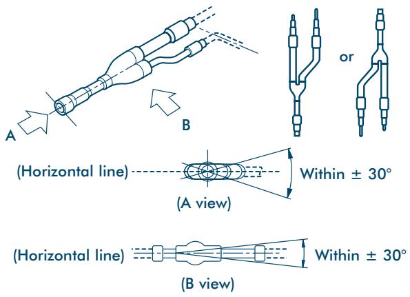
- Be sure to fit the insulation to the Y-shape branching joint supplied in the kit.
Cutting position
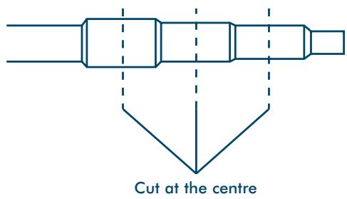
Cut the pipe at the centre of each connecting section, and remove burr.
Note: All dimensions in (mm)
Piping
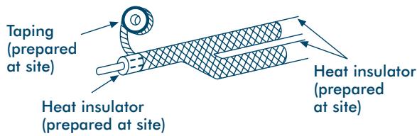
Heat Insulating the Branching Pipes
Ensure the pipe insulation covers the piping up to the brazed accessory joints, as this will eliminate ingress of water - tape the pipe insulation to a thickness of 10mm or more, as shown.
RBM-Y129 (Gas side) (Prepared at site)
RBM-Y071 (Gas side, Liquid side),
RBM-Y129 (Liquid side)
Use insulator with a heat resistance of 120^ or over for gas pipes. To insulate the Branching Pipes, use a T-Shaped Joint cover with a thickness of 10mm or over - or a machined insulation portion, as shown.
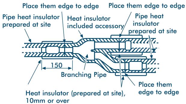
After the heat insulating, tape to seal.
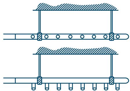
Branching Header
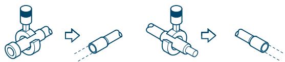
When the selected pipe size prepared at site differs from the size of the branching header pipe, cut the centre of the connecting section with a pipe cutter as shown.
If the number of Indoor Units to be connected is less than the number of connections on the Branching Header, braze a pipe cap to the unused connectors.
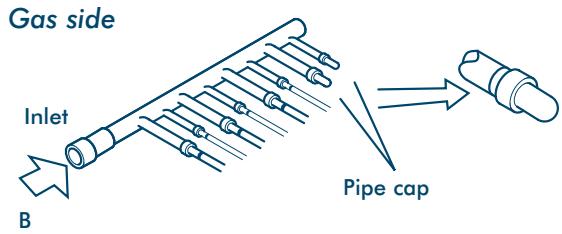
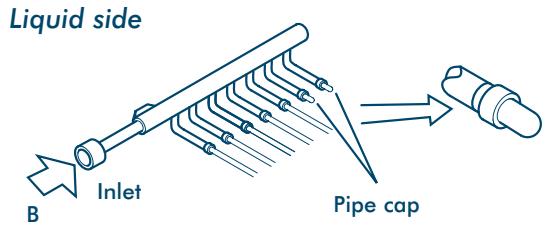
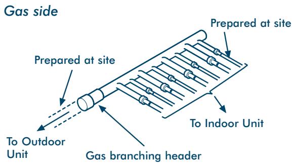
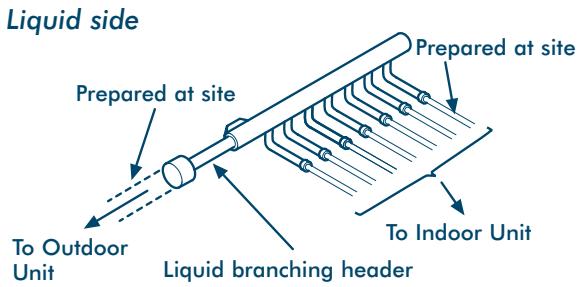
Piping
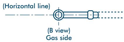
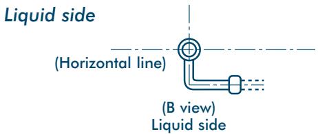
- Install the branching header so that it branches horizontally. DO NOT install vertically.
Gas side
- Be sure to insulate the branching header with the insulation provided.
- When routing the branching header at the liquid side from the opposite side, cut both ends and use a pipe cap (not supplied), as shown.
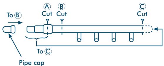
- Support of branching header
Set a hanging metal support (prepared at site) for the branching header, after fitting heat insulation.
- Cutting position
Cut the centre of each connecting section, and remove burr.
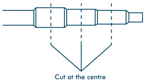
Use a mini-cutter to cut branching headers up to 22.2.
Notes:
- Make sure there's a straight run of pipe at least 300mm long at the inlet side of Y-shaped Branching Joints and Branching Headers.
- Install Y-shaped Branching Joint so they branch horizontally or vertically. In horizontal installations, set within ± 30^ .
- Install Branching Headers so they branch horizontally.
- Do not use T-shaped Branching Joints for Branching Sections.
- When using Y-Branches or Header Branches to prevent incorrect piping, attach a line number or name to each pipe.
Note: All dimensions in (mm)
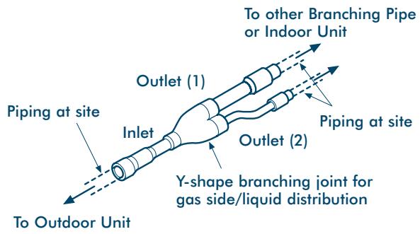
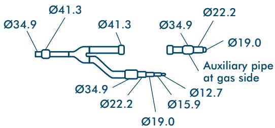
T-shape Branching Joint - to Connect Outdoor Units
Branching Pipes at Gas Side/Liquid Side
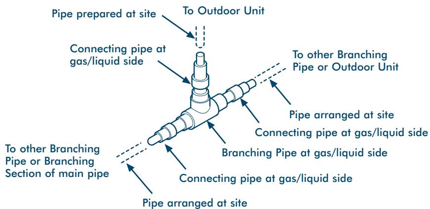
- Use the included connecting pipes for gas/liquid sides to match to the appropriate pipe size. (The diagram shows a connecting example.)
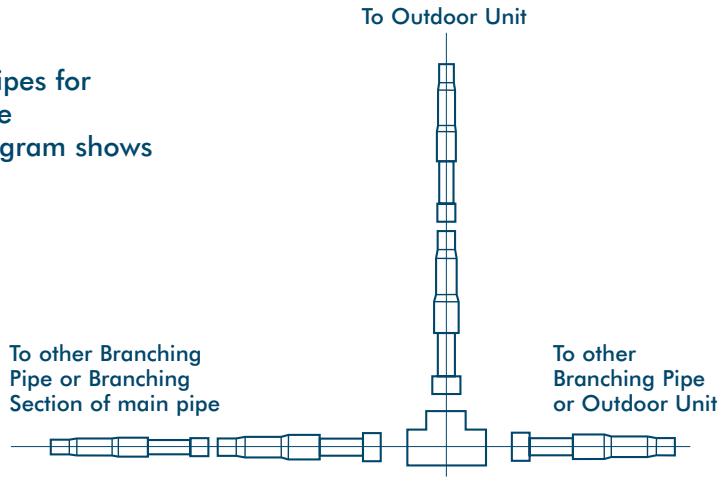
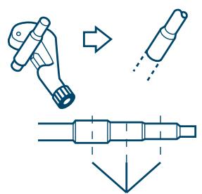
Cut the centre

- Cutting position of connecting pipe
When the selected pipe size prepared at site differs from the size of the Branching Pipe, cut the centre of the connecting section with a pipe cutter.
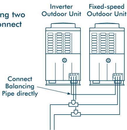
Installation of Gas/Liquid Branching Pipes
Balancing Branch Pipes (Oil)
When combining two units, connect directly.
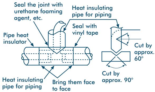
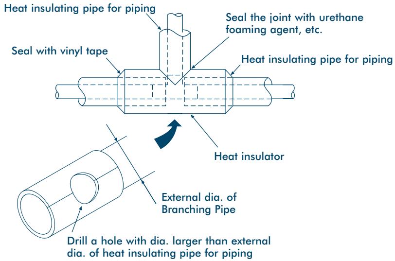
Heat Insulation
Insulate liquid side, gas side and Balancing Pipes separately.
Use insulator with a resistance of 120^ + for gas pipes.
To insulate the Branching Pipes, use a T-Shaped Joint cover with a thickness of 10mm or over – or the machined one included. (Insulation for branching is not included.)
To prevent condensation or dripping – seal the Branching Pipe securely, with no gaps.
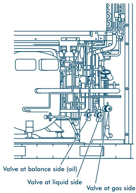
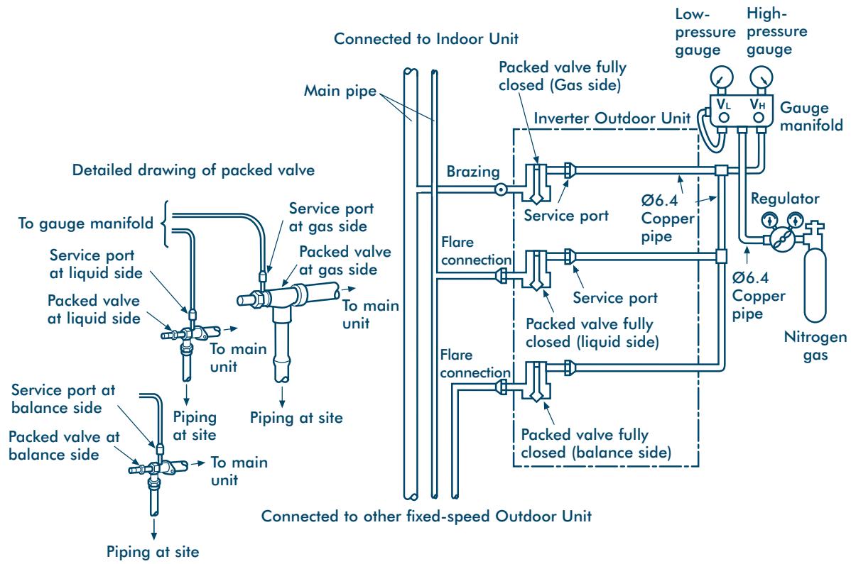
Airtight Test
Carry out an airtight test after the refrigerant piping is complete. For an airtight test, connect a nitrogen gas bottle as shown, and apply pressure.
- Be sure to carry out the test from the service ports of the packed valves at both the gas side and balance side.
- Complete the airtight test on the service ports at liquid, gas and balance sides of the Inverter Outdoor Unit ONLY.
- Keep all of the valves at gas, liquid and balance sides fully closed. Nitrogen may enter the cycle of the Outdoor Unit. Therefore, re-tighten the valve rod before applying pressure. (For all valves at gas, liquid and balance sides.)
- For each refrigerant line, apply pressure gradually at gas, liquid and balance sides.
Be sure to apply pressure at gas, liquid and balance sides.
Never use oxygen, or a flammable noxious gas.
To detect a large leakage
STEP 1: 0.3MPa (3.0kg / cm^2G) Apply pressure for 3 minutes or more
STEP 2: 1.5 MPa ( 15 ~kg / cm^2 G) Apply pressure for 3 minutes or more
To detect a fine leakage
STEP 3: 3.0MPa (30kg / cm^2G) Apply pressure for 24 hours
- Check for a reduction in pressure.
If there is no reduction in pressure this is acceptable.
If there is a reduction in pressure check for leakage.
(Note: If there is a difference of ambient temp. between when the pressure was applied and 24 hours later, then pressure could change by approx. 0.01MPa (0.1kg / cm^2G) - so correct the pressure change.)
Note: All dimensions in (mm)
Leak Position Check
If a pressure drop is detected, check for leakage at connecting points. Locate the leakage by listening, feeling, using foaming agent etc. – then re-braze or re-tighten.
Air Purge
Using a vacuum pump, complete an air purge. Never use refrigerant gas.
After the airtight test, discharge the nitrogen gas.
- Connect a gauge manifold to the service port at liquid side, gas side and balance side, and connect a vacuum pump as shown.
- Be sure to vacuum at liquid, gas and balance sides.
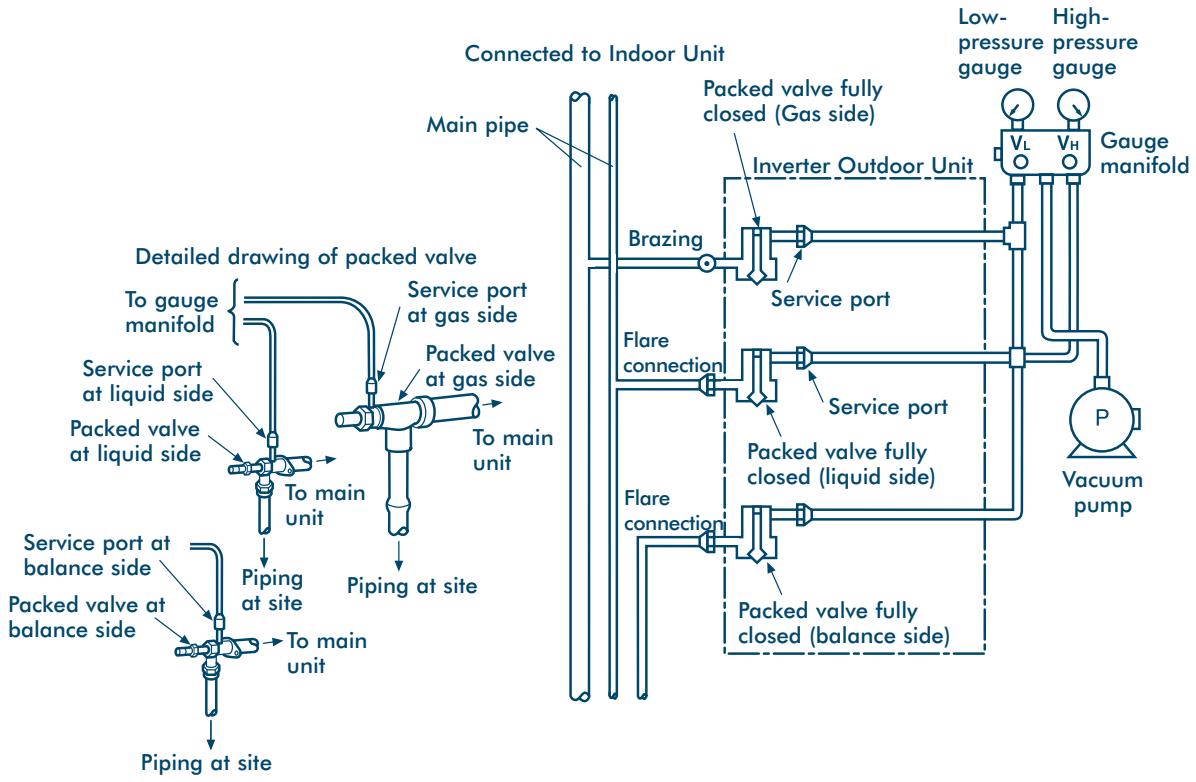
- Use a vacuum pump with high vacuum carry-over degree (0.750mmHg or less) and large displacement (40L/min. or more).
- Perform vacuuming for 2 or 3 hours, though time depends on pipe length. Confirm that all packed valves at liquid, gas and balance sides are fully closed.
- If vacuum does not reach 0.750mmHg or less even after pumping for 2 hours or more, carry on for another hour. If it is still not reached even after 3 hours, check for leaks.
- When vacuum has reached 0.750mmHg or less after 2 hours or more, fully close valves VL and VH on the gauge manifold, stop the vacuum pump, leave for 1 hour, and then confirm the vacuum reading has not changed. If it has, there may be a leak – so carry out a full piping check.
- After the procedure has been completed, replace the vacuum pump with a refrigerant bottle and add the refrigerant.
Adding the Refrigerant
After the airtight test, replace the vacuum pump with a refrigerant bottle to charge the system.
Calculating the Additional Refrigerant Required
The refrigerant amount at shipment does not include the refrigerant needed for the piping - so first calculate this amount, and then add it.
Refrigerant charge amount shipped from the factory
| Outdoor Unit Model name MM- | A0224HT | A0280HT | A0160HX | A0224HX | A0280HX |
| Charging amount (kg) | 15.5 | 17.0 | 5.0 | 7.0 | 9.0 |
The amount of additional refrigerant is calculated from the size of the liquid pipe, and its real length.
Additional refrigerant charge amount at site =
Real length of liquid pipe x Additional refrigerant charge amount per liquid pipe 1m.
Example:
Additional charge amount R (kg) = (L1 × 0.030kg/m) + (L2 × 0.065kg/m) + (L3 × 0.115kg/m)
L1: Real total length of liquid pipe 6.4 (m)
L2: Real total length of liquid pipe 9.5 (m)
L3: Real total length of liquid pipe 12.7 (m)
| Pipe dia. at liquid side | Additional refrigerant amount/1m |
| Ø6.4 | 0.030kg |
| Ø9.5 | 0.065kg |
| Ø12.7 | 0.115kg |
| Ø15.9 | 0.190kg |
| Ø19.0 | 0.290kg |
| Ø22.2 | 0.420kg |
Charging the System
- Keeping the Outdoor Unit valve closed, charge the refrigerant from the service port on the liquid side.
- If the specified amount of refrigerant cannot be charged - fully open the Outdoor Unit's valves on the liquid, gas and balance sides, then perform the cooling operation with the valve at the gas side slightly closed.
- If leaks cause a shortage of refrigerant – recover the refrigerant from the system, and recharge with new refrigerant to the total refrigerant charge.
Note: All dimensions in (mm)
Piping
Additional Charge Amounts
| Pipe Length | Liquid Pipe Diameter (mm) | |||||
| (m) | Ø6.4 | Ø9.5 | Ø12.7 | Ø15.9 | Ø19.0 | Ø22.2 |
| 1 | 0.030 | 0.065 | 0.115 | 0.190 | 0.290 | 0.420 |
| 2 | 0.060 | 0.130 | 0.230 | 0.380 | 0.580 | 0.840 |
| 3 | 0.090 | 0.195 | 0.345 | 0.570 | 0.870 | 1.260 |
| 4 | 0.120 | 0.260 | 0.460 | 0.760 | 1.160 | 1.680 |
| 5 | 0.150 | 0.325 | 0.575 | 0.950 | 1.450 | 2.100 |
| 6 | 0.180 | 0.390 | 0.690 | 1.140 | 1.740 | 2.520 |
| 7 | 0.210 | 0.455 | 0.805 | 1.330 | 2.030 | 2.940 |
| 8 | 0.240 | 0.520 | 0.920 | 1.520 | 2.320 | 3.360 |
| 9 | 0.270 | 0.585 | 1.035 | 1.710 | 2.610 | 3.780 |
| 10 | 0.300 | 0.650 | 1.150 | 1.900 | 2.900 | 4.200 |
| 11 | 0.330 | 0.715 | 1.265 | 2.090 | 3.190 | 4.620 |
| 12 | 0.360 | 0.780 | 1.380 | 2.280 | 3.480 | 5.040 |
| 13 | 0.390 | 0.845 | 1.495 | 2.470 | 3.770 | 5.460 |
| 14 | 0.420 | 0.910 | 1.610 | 2.660 | 4.060 | 5.880 |
| 15 | 0.450 | 0.975 | 1.725 | 2.850 | 4.350 | 6.300 |
| 16 | 0.480 | 1.040 | 1.840 | 3.040 | 4.640 | 6.720 |
| 17 | 0.510 | 1.105 | 1.955 | 3.230 | 4.930 | 7.140 |
| 18 | 0.540 | 1.170 | 2.070 | 3.420 | 5.220 | 7.560 |
| 19 | 0.570 | 1.235 | 2.185 | 3.610 | 5.510 | 7.980 |
| 20 | 0.600 | 1.300 | 2.300 | 3.800 | 5.800 | 8.400 |
| 21 | 0.630 | 1.365 | 2.415 | 3.990 | 6.090 | 8.820 |
| 22 | 0.660 | 1.430 | 2.530 | 4.180 | 6.380 | 9.240 |
| 23 | 0.690 | 1.495 | 2.645 | 4.370 | 6.670 | 9.660 |
| 24 | 0.720 | 1.560 | 2.760 | 4.560 | 6.960 | 10.080 |
| 25 | 0.750 | 1.625 | 2.875 | 4.750 | 7.250 | 10.500 |
| 26 | 0.780 | 1.690 | 2.990 | 4.940 | 7.540 | 10.920 |
| 27 | 0.810 | 1.755 | 3.105 | 5.130 | 7.830 | 11.340 |
| 28 | 0.840 | 1.820 | 3.220 | 5.320 | 8.120 | 11.760 |
| 29 | 0.870 | 1.885 | 3.335 | 5.510 | 8.410 | 12.180 |
| 30 | 0.900 | 1.950 | 3.450 | 5.700 | 8.700 | 12.600 |
| 31 | 0.930 | 2.015 | 3.565 | 5.890 | 8.990 | 13.020 |
| 32 | 0.960 | 2.080 | 3.680 | 6.080 | 9.280 | 13.440 |
| 33 | 0.990 | 2.145 | 3.795 | 6.270 | 9.570 | 13.860 |
| 34 | 1.020 | 2.210 | 3.910 | 6.460 | 9.860 | 14.280 |
| 35 | 1.050 | 2.275 | 4.025 | 6.650 | 10.150 | 14.700 |
| 36 | 1.080 | 2.340 | 4.140 | 6.840 | 10.440 | 15.120 |
| 37 | 1.110 | 2.405 | 4.255 | 7.030 | 10.730 | 15.540 |
| 38 | 1.140 | 2.470 | 4.370 | 7.220 | 11.020 | 15.960 |
| 39 | 1.170 | 2.535 | 4.485 | 7.410 | 11.310 | 16.380 |
| 40 | 1.200 | 2.600 | 4.600 | 7.600 | 11.600 | 16.800 |
| 41 | 1.230 | 2.665 | 4.715 | 7.790 | 11.890 | 17.220 |
| 42 | 1.260 | 2.730 | 4.830 | 7.980 | 12.180 | 17.640 |
| 43 | 1.290 | 2.795 | 4.945 | 8.170 | 12.470 | 18.060 |
| 44 | 1.320 | 2.860 | 5.060 | 8.360 | 12.760 | 18.480 |
| 45 | 1.350 | 2.925 | 5.175 | 8.550 | 13.050 | 18.900 |
| 46 | 1.380 | 2.990 | 5.290 | 8.740 | 13.340 | 19.320 |
| 47 | 1.410 | 3.055 | 5.405 | 8.930 | 13.630 | 19.740 |
| 48 | 1.440 | 3.120 | 5.520 | 9.120 | 13.920 | 20.160 |
| 49 | 1.470 | 3.185 | 5.635 | 9.310 | 14.210 | 20.580 |
| 50 | 1.500 | 3.250 | 5.750 | 9.500 | 14.500 | 21.000 |
| 51 | 1.530 | 3.315 | 5.865 | 9.690 | 14.790 | 21.420 |
| 52 | 1.560 | 3.380 | 5.980 | 9.880 | 15.080 | 21.840 |
| 53 | 1.590 | 3.445 | 6.095 | 10.070 | 15.370 | 22.260 |
| 54 | 1.620 | 3.510 | 6.210 | 10.260 | 15.660 | 22.680 |
| 55 | 1.650 | 3.575 | 6.325 | 10.450 | 15.950 | 21.100 |
| 56 | 1.680 | 3.640 | 6.440 | 10.640 | 16.240 | 23.520 |
| 57 | 1.710 | 3.705 | 6.555 | 10.830 | 16.530 | 23.940 |
| 58 | 1.740 | 3.770 | 6.670 | 11.020 | 16.820 | 24.360 |
| 59 | 1.770 | 3.835 | 6.785 | 11.210 | 17.110 | 24.780 |
| 60 | 1.800 | 3.900 | 6.900 | 11.400 | 17.400 | 25.200 |
Wiring
Precautions
The circuit protection device will protect the supply cable against over current. The circuit protection must be selected having due regard to the compressor starting current, such that the supply cables when sized correctly, are protected.
The cable should be selected to match the nominal load of the system, in addition to the losses associated with corrections for length, temperature, impedance etc., in accordance with local codes of practice.
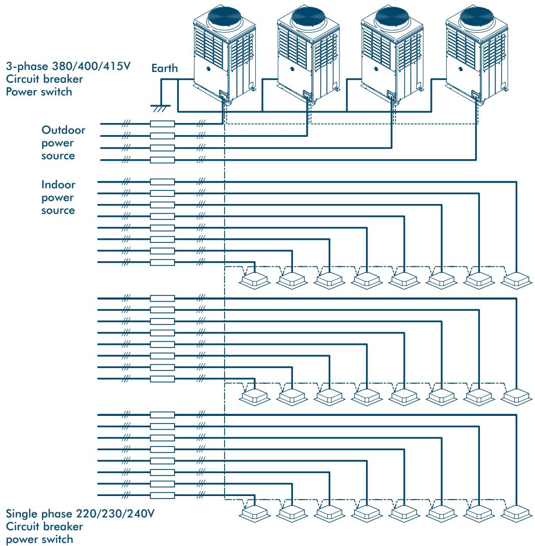
General
- Observe the Electrical Equipment Engineering Standard and Indoor Wiring Regulations.
- The refrigerant piping and corresponding control wiring should be routed closely together.
- For the control wires connecting the Indoor Units, Outdoor Units, and between indoor and Outdoor Units, the use of double-core shielded wires is recommended to prevent interference.
- Provide each Indoor Unit with a separate method of isolation.
- Supply power to each Outdoor Unit via a dedicated branch circuit, and provide a circuit breaker for each Outdoor Unit.
- Connect the power supply cables to the Outdoor Unit via the built in isolator.
Note: Provide separate power supplies for indoor and Outdoor Units.
Wiring System Overview
Wiring
Table below shows the supply requirements
| MODEL | STARTING CURRENT (A) | RUNNING CURRENT (A) | POWER COMSUMPTION (KW) |
| MM-A0280HT | 60 | 19.7 | 12.6 |
| MM-A0224HT | 60 | 16.2 | 10.2 |
| MM-A0280HX | 60 | 21.8 | 12.8 |
| MM-A0224HX | 60 | 18.7 | 10.6 |
| MM-A0160HX | 60 | 10.6 | 5.9 |
Note: The above data is based on the following conditions:
Indoor Temperature: 27^ C DB/19°C WB
Outdoor Temperature: 35^ C DB/25°C WB
Connecting the Power Source Cable and Control Cable
Insert power source cable and control cable after removing the knockout in the Piping/Wiring Panel on the front side of the main unit.
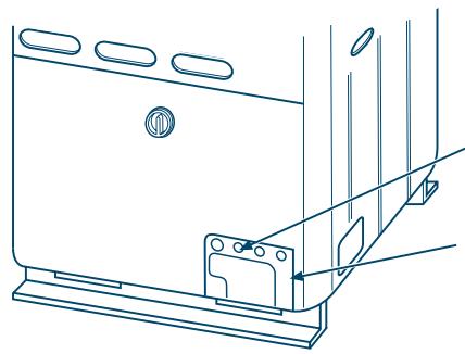
Knock out (x4) for control cable and power source cables.
Piping/Wiring Panel
Power Source cable
- Connect the electric cables and earth wire to the Outdoor isolator terminal block through a notched section at side of the electric parts box, and fix with a clamp.
- Bundle the electric cables using the hole so that they are in the notched section of the electric parts box.
Control Cable
- Connect the control cable between Indoor and Outdoor Units plus the control cable between Outdoor Units to P-Q terminal section through a hole at the side of the electric parts box, and fix with a clamp.
- Use control cable with 2-core shield wire (1.25mm² or more) in order to prevent interference. (Non-polarity.)
Notes:
1 Be sure to separate the power source cables and each control cable.
2 Arrange the power source cables and each control cable so they are not in contact with the bottom surface of the main unit.
3 A terminal block (X-Y) for connecting the optional Central Remote Controller is provided on the Inverter Unit.
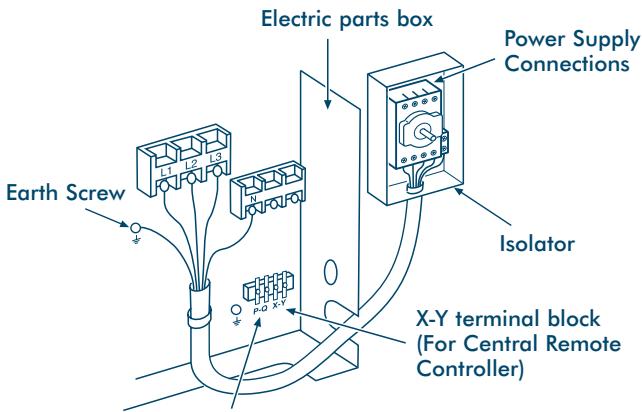
P-Q terminal block
(For wiring for control cable between Indoor/Outdoor Unit
For wiring for control cable between Outdoor Units)
Earth Screw (Shield Wire)
Control Wiring Overview
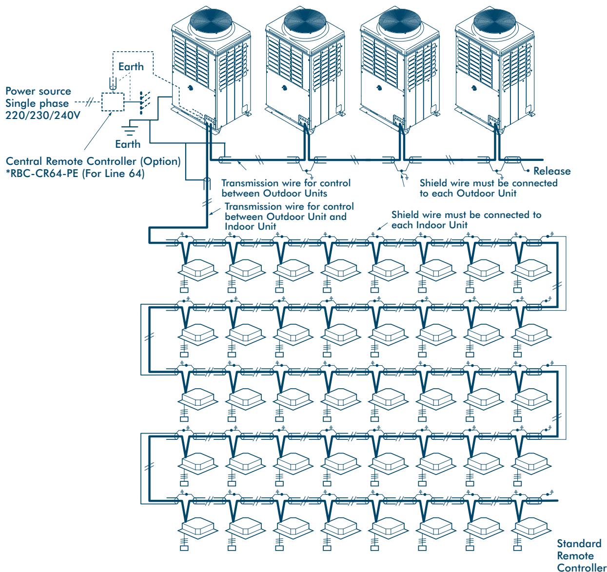
Wire specification, quantity, size of crossover wire (transmission wire) and Remote Controller wire.
| Name | Qty | Size | Specification |
| Crossover wire (between indoor and outdoor units, between outdoor units) | 2 cores | 1.25mm² ≤ 500m | Shielded wire |
| Remote controller wiring | 3 cores | 0.3mm ≤ 200m, 200m < 0.75mm ≤ 500m | |
| Central control remote controller transmission wire | 2 cores | 1.25mm ≤ 500m, 500m < 2.0mm ≤ 1000m |
- Crossover lines and lines from the central Remote Controller use double-core non-polar wires. Use double-core shielded wires to prevent interference. Connect the ends of shielded wires and insulate the final end. Provide two ground points: one at the central Remote Controller and the other for the Outdoor Units.
- Use 3-core and polar wire for Remote Controller (A, B, C terminals). Use 2-core wire for grouping wiring of Remote Controller (B,C terminals).
- Be sure to divide the earth shield wires of the central Remote Controller and crossover into the separate lines (not crossed halfway).
Trial Operation
Contents
Final Installation Checks 39
Adjustment Before Trial Operation 39
Service Support Functions 40
Check Function for Connection of Refrigerant Pipes and Control Transmission Lines 40
Function to Start/Stop Indoor Units From an Outdoor Unit 41
Trial Cooling Operation Function 42
Collective Start/Stop (On/Off) Function 43
Individual Start/Stop (On/Off) Function 44
Alarm Clear Function 45
Clearing a Central Remote Controller/with 7 day Timer . . . . . . . . . . . . . . . . . . . . . . . . . . . . . . . . . . . . . . . . . .
Clearing the Interface PCB of an Inverter Outdoor Unit 45
Clearing an Alarm by Resetting the Power Source 46
Remote Controller Identification Function 46
Forcing the Electronic Control Valve (PMV) 'Fully Open'– on the Indoor Unit 47
Forcing the Electronic Control Valve (PMV) 'Fully Opened/Fully Closed' - on the Outdoor Unit 47
Trial Operation
Final Installation Checks
Precautions
Ensure that the electrical cable used for power supply and control of the system is unable to come into contact with either service valves or pipework which are not insulated.
Electrical Wiring
When installation is complete, check that all power supply and interconnecting wiring has been appropriately protected.
Refrigerant Piping
When refrigerant and drain piping have been completed, ensure that all pipework is fully insulated and apply finishing tape to seal the insulation.
Adjustment Before Trial Operation
Automatic Address Between Indoor and Outdoor Units
Turning on the power for the first time after the system has been installed starts the Automatic Address procedure. It usually takes between 3 and 5 minutes to complete – but in some cases, can take up to 20 minutes.
During Automatic Address the System cannot be Operated
If the Operate button on the indoor unit is pressed during Automatic Address, the following will happen:
- The operation light on the remote control will come on;
- The fan on the Indoor Unit will start or stop, according to the mode;
- Cool air will not come out, because the Outdoor Unit is off.
When Automatic Address procedure is complete, normal operation starts automatically.
Automatic Address Reactivation
Once control of the Indoor Unit has been confirmed, Automatic Address will only be reactivated when:
- the PC board of the Indoor Unit is replaced, and power is turned on for the first time.
- a new Indoor Unit is added, and power is turned on for the first time.
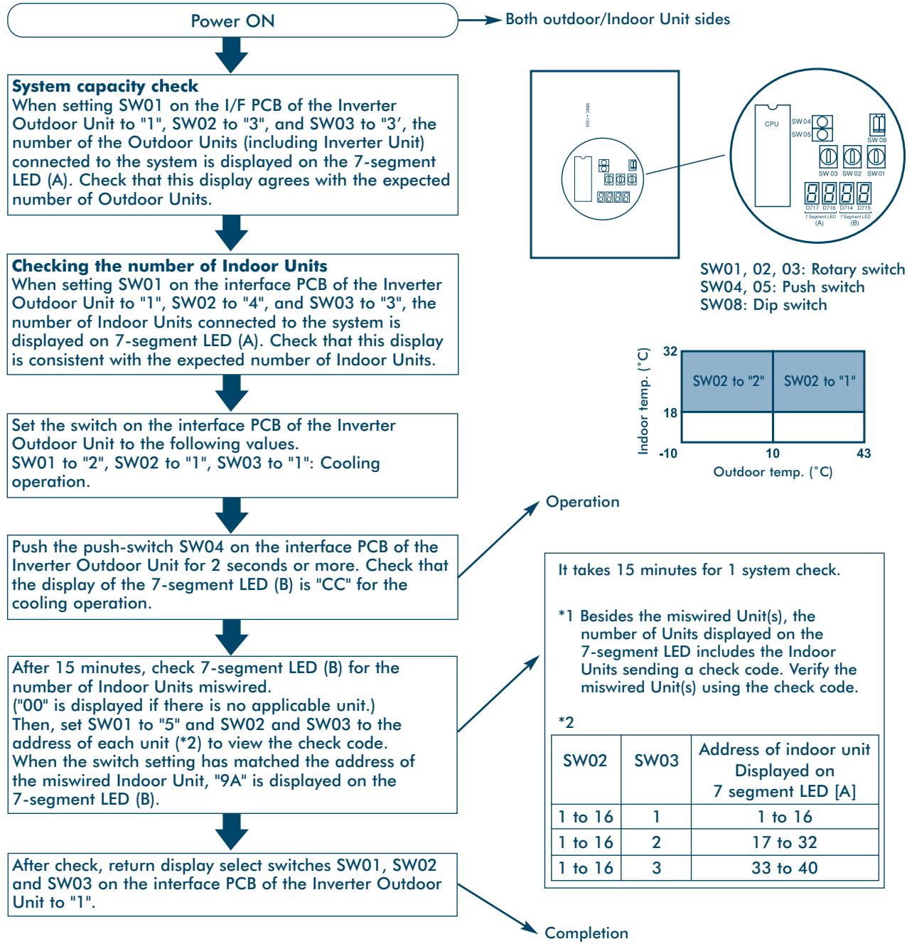
Check Function for Connection of Refrigerant Pipes and Control Transmission Lines
This function is provided to check misconnection of the refrigerant piping and the control transmission line between Indoor and Outdoor Units by the switches on the interface PCB of the Inverter Outdoor Unit.
However, be sure to check items described here before implementing this check function.
- When grouping operation of the Remote Controller is performed and the connected Outdoor Units are used, the check function does not work.
- Only use this facility to check lines one by one in a single Outdoor Unit. Checking multiple lines at the same time may cause faulty readings.
Procedure
Service Support Functions
Function to Start/Stop Indoor Units From an Outdoor Unit
| No. | Function | Outline | Clear Setup |
| (1) | Trial cooling operation | The modes of all the connected indoor units are collectively changed to trial cooling operation modes. NOTE: Control operation as same as that of normal trial operation from the remote controller is performed. | [Setup] Push SW04 for at least 2 seconds under condition of SW01 “2”, SW02 “5”. [Clear] Cleared from the remote controller when SW01 and SW02 are changed to other positions. |
| (2) | Collective operation | All the connected indoor units are operated collectively. NOTE: Operation contents follow to the setup on the remote controller. | [Setup] Push SW04 for at least 2 seconds under condition of SW01 “2”, SW02 “7”. [Clear] Cleared from the remote controller. |
| Collective stop | All the connected indoor units are stopped collectively. | [Setup] Push SW05 for at least 2 seconds under condition of SW01 “2”, SW02 “7”. [Clear] Cleared from the remote controller. | |
| (3) | Individual operation | The specified indoor unit is operated. NOTE: Operation contents follow to the setup on the remote controller. Other indoor units stay as they are. | [Setup] To start an indoor unit, set “16” in SW01 and the address number of the indoor unit (1 to 20) in SW02 and SW07, and then push SW04 for at least 2 seconds. [Clear] Cleared from the remote controller. |
| Individual stop | The specified indoor unit is stopped. NOTE: Other indoor units stay as they are. | [Setup] Push SW05 for at least 5 seconds. [Clear] Cleared from the remote controller. |
Note:
This start/stop function only sends mode signals for starting, stopping, operation, etc., from the Outdoor Unit to the Indoor Unit(s). If the Indoor Unit did not follow the sent signal, there is no function to re-send the signal and force the Unit to follow the command.
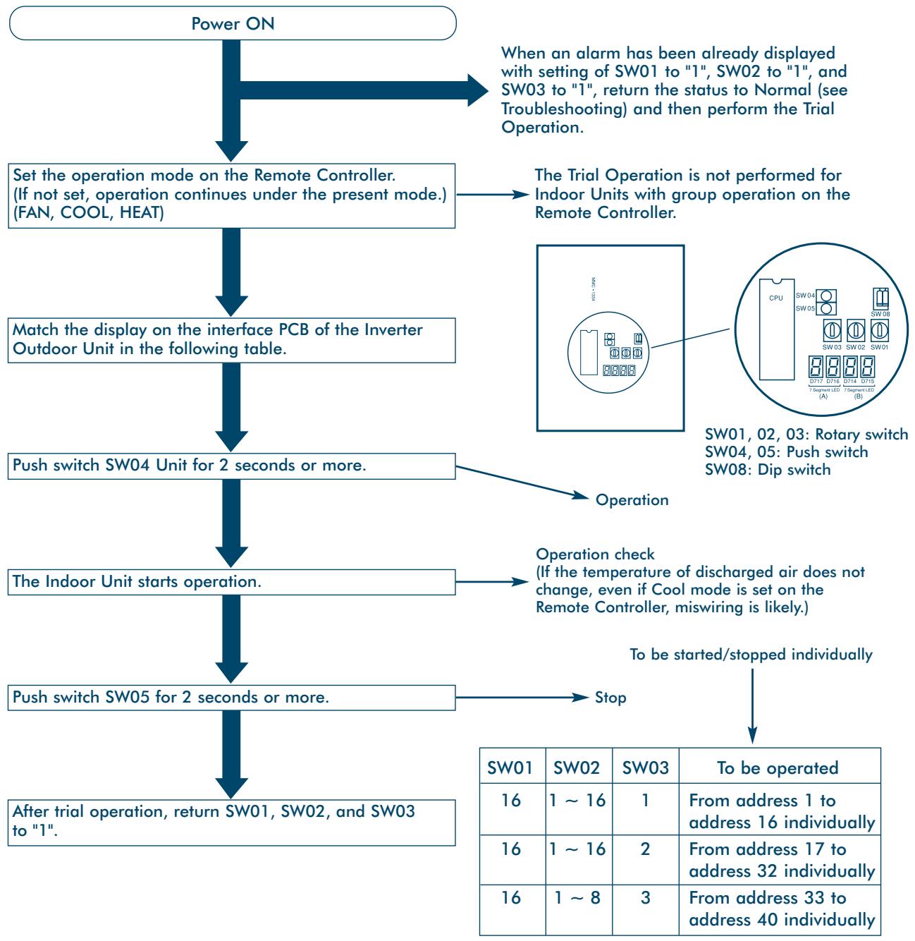
Trial Cooling Operation Function
This function changes the modes of all the Indoor Units to trial operation modes. It is operated by the switch on the interface PCB of the Inverter Outdoor Unit.
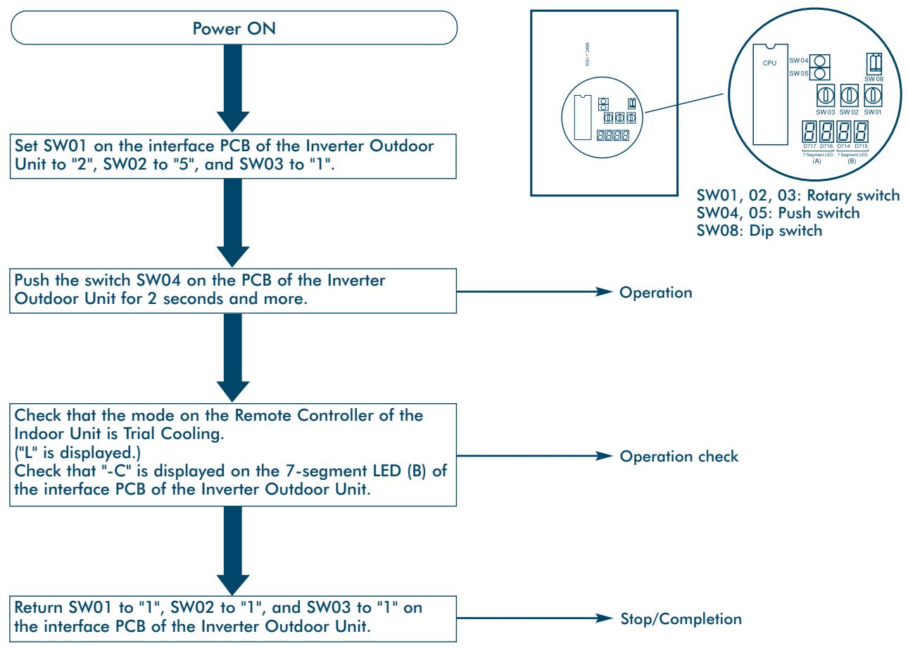
Procedure
Collective Start/Stop (On/Off) Function
This function starts/stops all the Indoor Units by the switch on interface PCB of the Inverter Outdoor Unit.
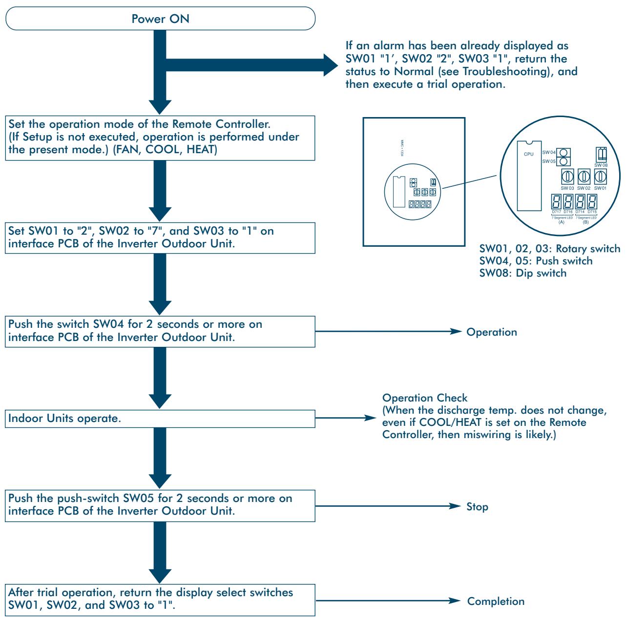
Procedure
Individual Start/Stop (On/Off) Function
This function starts/stops the Indoor Units individually by the switch on the interface PC board of the Inverter Outdoor Unit.
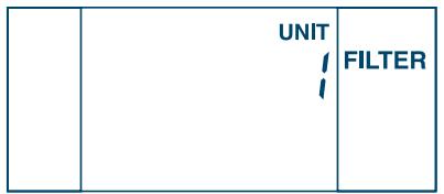
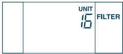
Set SW01 to "16", and SW02 and SW03 to the Indoor Unit to be operated. (See table.) The nominated Units will now operate.
(If the rotary switch of a nominated unit is set at anything from 2 to 16, it cannot start or stop individually. " _ " is displayed on LED 'B'.)
Procedure
Alarm Clear Function
Clearing a Central Remote Controller/with 7 day Timer
This clears the alarm so that the Outdoor Unit can resume operation without having to reset power.
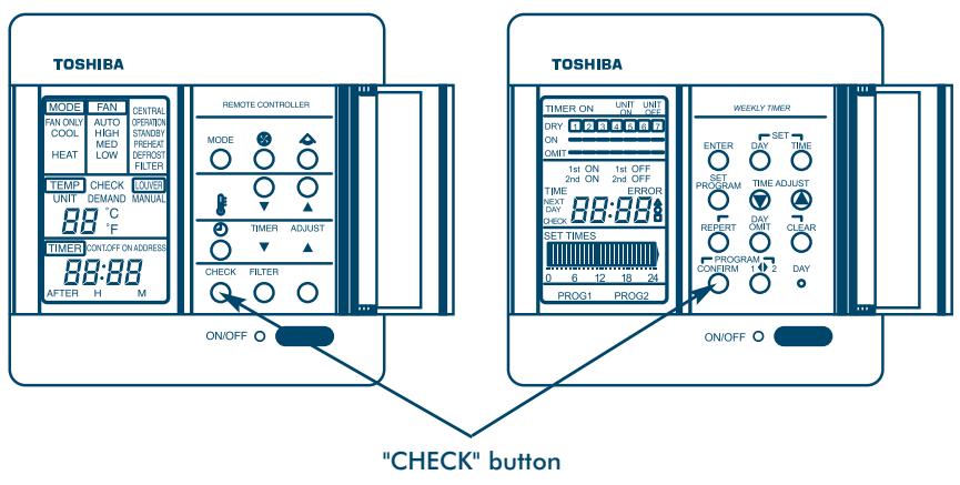
- Push the 'CHECK' button on the remote control panel for at least 5 seconds.
- To clear the check code for that Remote Controller - push the 'CHECK' button for at least 15 seconds. (Using the 'Reset' hole can also clear the check code.)
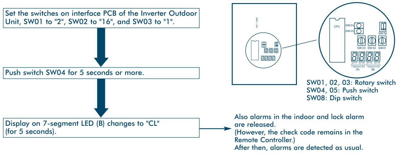
Clearing the Interface PCB of an Inverter Outdoor Unit
This clears the alarm so that the Outdoor Unit can resume operation without having to reset power. However, this does not clear the check code in the Remote Controller – this is done either by the method described previously, or by using the 'Reset' hole.
Procedure
Clearing an Alarm by Resetting the Power Source
Be sure to reset the power sources of both the Outdoor and Indoor Units.
- Turn the power OFF.
- Turn the power ON for the Outdoor Unit first.
- Turn the power ON for the Indoor Unit next.
Note:
Even if the power source of the Outdoor Unit is re-set, the fault code is still displayed on the Indoor Unit. To clear this, hold down the 'CHECK' button on the Remote Controller for at least 15 seconds.
Remote Controller Identification Function
This function identifies the Remote Controller connected to each Outdoor Unit.
Procedure
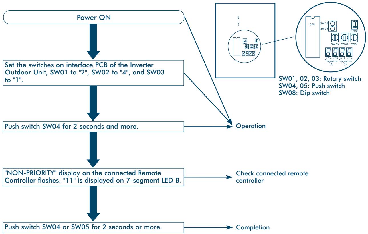
Other completion conditions:
1. Send operation continued for 10 minutes.
2. SW01, SW02 or SW03 moved to other position.
Service Support Functions
Forcing the Electronic Control Valve (PMV) 'Fully Open' – on the Indoor Unit
This function forces the electronic control valves open in all the Indoor Units for 2 minutes. It is activated by a switch on the interface PCB of the outdoor Inverter Unit.
Usually, turning on the power to an Indoor Unit once fully closes the PMV – this function is used when you want to open the PMV fully for operation after the power has been turned off a second time.
Procedure
Set SW01 to "2", SW02 to "3" and SW03 to "1" on interface PCB of the Inverter Outdoor Unit, and push SW04 for 2 seconds or more.
(7-segment LED [B] changes to "FF" for 2 minutes.)
Clear
Following Setup, the PMV automatically returns to its normal open pulse after 2 minutes. It is only opened fully for 2 minutes when it receives the FULL OPEN signal from the Outdoor Unit.
Forcing the Electronic Control Valve (PMV) 'Fully Opened/Fully Closed' – on the Outdoor Unit
This function opens or closes the electronic control valve of an Outdoor Unit for 2 minutes.
Fully Open
Short circuit CN30 on the interface PC board of the Inverter Outdoor Unit.
Fully Closed
Short circuit CN31 on the interface PC board of the Inverter Outdoor Unit.
Clear
Both Fully Open and Fully Closed return to the normal open pulse after 2 minutes. Be sure to remove the short circuit after confirmation.
Notes:
If bit 1 of DIP SW08 is ON PMV1 and PMV2 (Refrigerant Control) electronic control valves are turned on.
If bit 1 of DIP SW08 is OFF PMV3 (Cooling Bypass) electronic control valve is turned off.
Troubleshooting
Contents
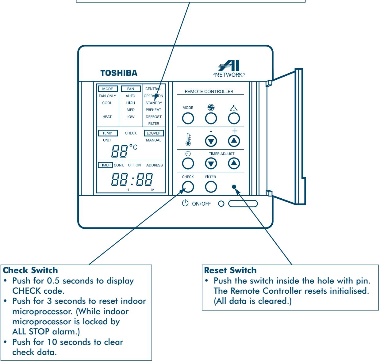
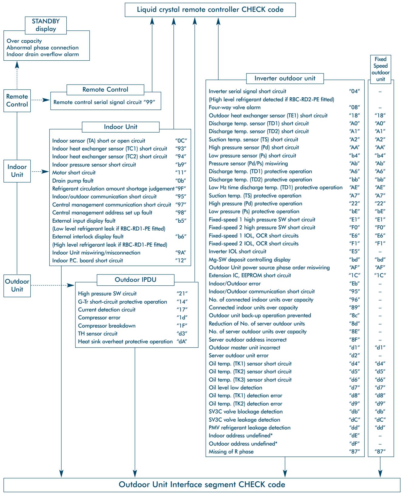
Remote Controller 'Check' Display 49
Main Remote Controller 49
Operating and Reading the Check Display 49
Room Remote Controller 51
Operating and Reading the Check Display 51
Self-Diagnostic Function 53
Check Codes - Remote Controller/Outdoor Unit .54
Cautions on Refrigerant Leakage 62
Troubleshooting
Remote Controller 'Check' Display
Main Remote Controller
Operating and Reading the Check Display
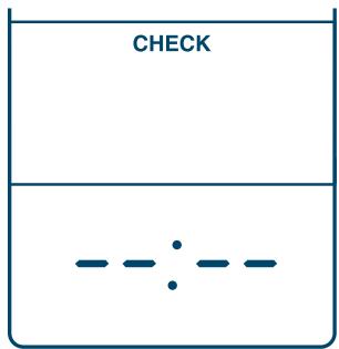
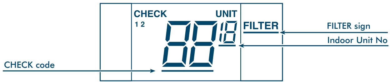
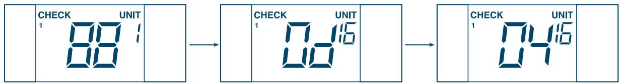
Push the CHECK button, and the identification number of the faulty Indoor Unit is shown in the Temperature Setup section of the display – and the check code is shown in the TIME section of the display.
If the air filter cleaning sign is displayed, the number of Indoor Units with a filter problem is indicated, followed by the check code.
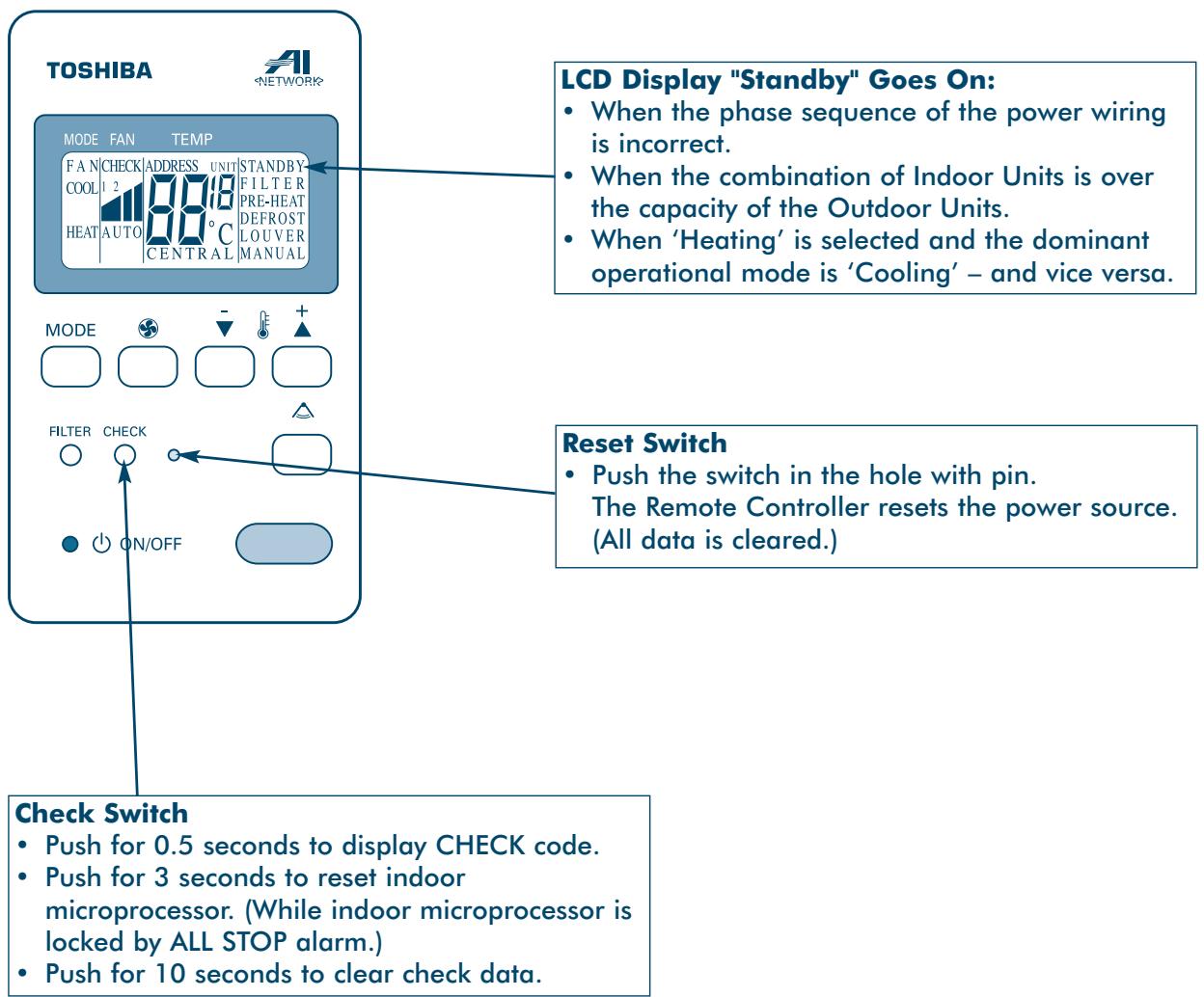
LCD Display "Standby" Mode:
- When combination of Indoor Units is over the capacity.
- When Indoor Unit with command excepted by operation mode select switch.
- When phase-sequence of power wiring is incorrect.
Troubleshooting
Remote Controller 'Check' Display
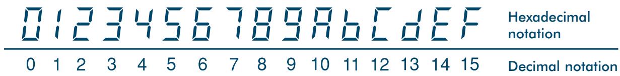
7-Segment Display
| 0 | 1 | 2 | 3 | 4 | 5 | 6 | 7 | 8 | 9 | 10 | 11 | 12 | 13 | 14 | 15 | Hexadecimal notation |
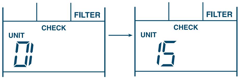
Filter Data
Example: A Filter signal is sent from No. 1 and No. 15 units under grouping operation.
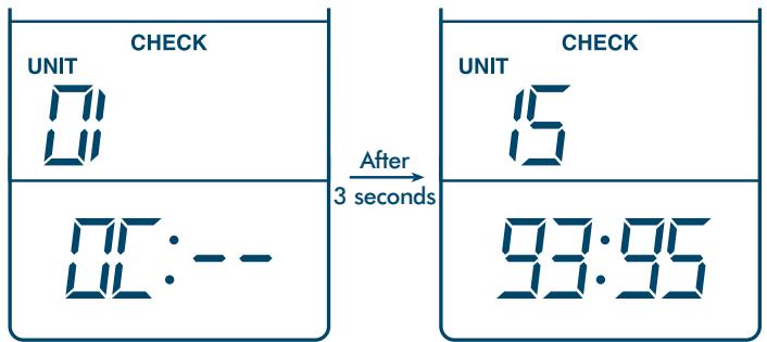
Check Data
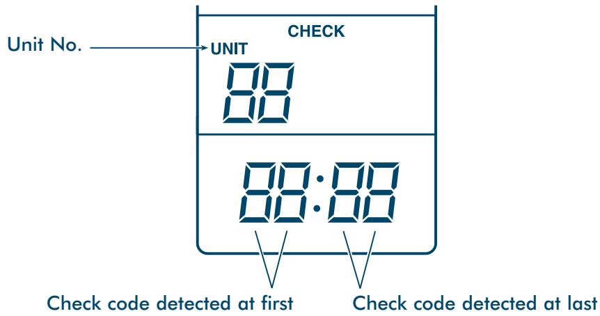
Example: Room Temp. sensor of No. 1 is defective. In No. 15, first the Heat Exchanger sensor has failed. Next, the indoor/outdoor inter-unit wire (bus communication line) is defective.
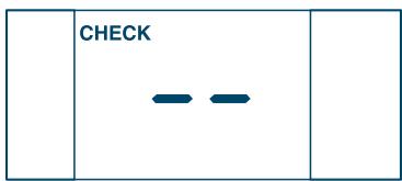
Example: There is no check data.
Troubleshooting
Remote Controller 'Check' Display
Room Remote Controller
Operating and Reading the Check Display
Push the CHECK button, and the identification number of the faulty Indoor Unit (1 - 16) is shown in the Temperature Setup section of the display - along with the check codes of up to 2 problems.
If there is a filter display, the number of the Indoor Unit with a filter problem is shown on the right.
Troubleshooting
Remote Controller 'Check' Display
7-Segment Display
Display on Check Monitor
Filter Data
Example: A Filter signal is sent from No. 1 and No. 16 units under grouping operation.
Check Data
Example: Room temp. sensor of No. 1 is defective.
In No.16, first the heat exchanger sensor has failed.
Next, inter-unit wire (serial signal line) of indoor/outdoor is defective.
Example: There is no check data.
Troubleshooting
Self-Diagnostic Function
*: No display on the remote controller
Note: To retrieve fault codes, ensure rotary switches 1, 2 and 3 on the Outdoor Interface PCB (MCC-1343-01) are all set to 1 (factory default setting).
Troubleshooting
Check Codes - Remote Controller/Outdoor Unit
| Check code | Detected position | Check code name | Cause | Problem detection condition | Check item |
| 04 | Interface | Inverter communication alarm | Inverter serial signal | Serial signal from inverter was interrupted. | ·Outdoor PC. board (Interface, INV) error. ·Check communication connector (CN600) between outdoor interface and INV PC. boards. ·Check integrity of refrigeration pipework |
| High level refrigerant detected if RBC-RD2-PE is fitted | 1000ppm refrigerant detected in compressor housing | ||||
| 08 | Interface | Four-way valve circuit | 4 way valve | Abnormal refrigeration cycle data detected during heating operation. | (Check all Outdoor Units) ·Check 4 way valve body error. ·Check 4 way valve coil and connection. ·Check resistance characteristics of TS and TE sensors ·Check output voltage characteristics of Pd and Ps pressure sensors. ·Check fixed speed compressor power supply wiring and magnetic switch error. |
| 0b | Indoor | Indoor drain overflow alarm | Float switch | ·Float switch operates continuously for 2 minutes. ·Float switch circuit disconnected or connector was out of place. | ·Check connection of float switch connector (CN10). ·Check drain pump operation. ·Check drain pump circuit. ·Check blockage of water drain pipe. ·Check indoor PC. board error. |
| 0C | Indoor | Indoor TA sensor alarm | Indoor temp. sensor (TA) | Sensor resistance value was infinity or zero (Open, Short). | ·Check connection and wiring of TA connector (CN04). ·Check characteristics of TA sensor resistance value. ·Check indoor PC. board error. |
| 11 | Indoor | Indoor fan motor alarm | Indoor fan motor circuit | Status that detection value of motor speed was out of target was detected continuously. | ·Check connection and wiring of fan connector (CN07, CN18). ·Check running condenser error for indoor fan. ·Check fan motor error. ·Check indoor PC. board error. ·Check effect of outside air process (OA). |
| 12 | Indoor | Other indoor error | Indoor PC. board (EEPROM/Peripheral circuit) | Indoor PC. board did not operate correctly. | ·Check power source voltage. ·Check noise of peripheral equipment. ·Check power source transformer output voltage (DC12V). |
| 14 | Inverter | G-Tr short-circuit protective system error | Inverter over-current protective circuit | Instantaneous over-current was detected when inverter compressor was activated. | ·Check power source wiring. ·Check connection of connector on inverter PC. board. ·Check reactor connection. ·Check AC fuse disconnection. ·Check cause of abnormal overload operation. ·Check inverter compressor error and rare short. ·IGBT conductive check. ·Check shortage of capacitor capacity. ·Check outdoor PC. board (INV) error. |
Troubleshooting
Check Codes - Remote Controller/Outdoor Unit
| Check code | Detected position | Check code name | Cause | Problem detection condition | Check item |
| 17 | Inverter | Current detection circuit system alarm | Inverter current detection circuit | Current flows over the set value when inverter compressor stop was detected. | • Check wiring of current detection circuit system. • Check outdoor P.C. board (INV) error. |
| 18 | Interface | TE1 sensor alarm | Outdoor heat exchanger sensor (TE1) | Sensor resistance value was infinity or zero (Open, Short) (automatic back-up operation after judgment). | • Check connection of TE1 sensor connector. • Check characteristics of TE1 sensor resistance value. • Check outdoor P.C. board (Interface) error. |
| 1C | Interface | Extension IC, EEPROM alarm | Outdoor interface P.C. board circuit | Outdoor P.C. board (Interface) did not operate correctly. | • Check power source voltage. • Check power source noise. • Check outdoor P.C. board (Interface) error. |
| 1d | Outdoor | Compressor alarm | Inverter compressor system circuit | Over-current was detected several seconds after inverter compressor was activated. | • Check inverter compressor lock. • Check power source voltage (AC380 to 415V ± 10%). • Check wiring of inverter compressor system and miss-phase. • Check connection of connector on inverter P.C. board. • Conductive check for crank case heater. (Activation error check by liquid stagnation in compressor). • Check outdoor P.C. board (INV) error. |
| 1F | Outdoor | Compressor break down | Inverter current detection circuit | After inverter frequency reduced by current release, over-current was detected and stopped. | • Check power source voltage (AC380 to 415V ± 10%). • Check cause of abnormal overload operation. • Check current sensor detection circuit system. • Check outdoor P.C. board (INV) error. |
Troubleshooting
Check Codes - Remote Controller/Outdoor Unit
| Check code | Detected position | Check code name | Cause | Problem detection condition | Check item |
| 21 | Outdoor | · Inverter high-pressure SW system alarm | Inverter high-pressure SW system circuit | High-pressure SW or IOL operated. · High-pressure Pd ≥ 2.5MPaG; [21] is displayed · High-pressure Pd < 2.5MPaG; [E5] is displayed | · Check inverter high-pressure SW error. · Check IOL operation and case temp. up. (Check cause of overload operation.) · Check service valve full open. · Check connection of outdoor fan connector. · Check outdoor fan motor, running condenser error. · Check blockage of outdoor PMV. 1) Refrigerant reducing circuit (PMV1, PMV2). 2) Cooling bypass circuit (PMV3). 3) Liquid line stopping check valve (Cooling only model). · Check blockage of outdoor/indoor heat exchanger. · Short-circuit status between outdoor discharge air and suction air. · Check Pd pressure sensor error. · Check blockage of hot gas bypass SV2 circuit. · Check outdoor P.C. board (Interface) error. · Check open valve status of indoor PMV. · Check miswiring of communication line between indoor and outdoor. |
| 22 | Interface | High-pressure protective operation Pd sensor detection value | High pressure up protection by high-pressure | Pd sensor detected 3.3MPaG or more. | · Check Pd pressure sensor error. · Check service valve full open. · Check cause of overload operation. · Check connection of outdoor fan connector. · Check outdoor fan motor, running condenser error. · Check blockage of outdoor PMV. 1) Refrigerant reducing circuit (PMV1, PMV2). 2) Liquid line stopping check valve (Cooling only model). · Check blockage of outdoor/indoor heat exchanger. · Short-circuit status between outdoor discharge air and suction air. · Check blockage of hot gas bypass SV2 circuit. · Check outdoor P.C. board (Interface) error. · Check indoor side fan system error (cause of air volume down). · Check open valve status of indoor PMV. · Check miswiring of communication line between indoor and outdoor. |
Troubleshooting
Check Codes - Remote Controller/Outdoor Unit
| Check code | Detected position | Check code name | Cause | Problem detection condition | Check item |
| 89 | Interface | Indoor capacity over | Total connected capacity of indoor units greater than outdoor units | Total capacity of indoor units was 135% more than total capacity of outdoor units. | • Check indoor unit connection capacity. • Check indoor unit HP capacity. • Check outdoor HP setup. • Check outdoor P.C. board (INV) error. |
| 8C | Interface | Outdoor unit back-up operation prevented | Heat mode selection during set-up | Operation mode of the system changed to HEAT during operation setup of outdoor unit. | • If outdoor unit back-up operation is being set-up heating operation is not available. |
| 8d | Interface | Reduction of No. of connected outdoors | No. of connected outdoor units communication | No. of connected outdoor units was judged to be less than No.of units stored in memory of EEPROM. [NOTE] If this code is displayed when back-up operation of outdoor error was performed, set “Alarm clear”. | • Check connection of communication connector. • Check communication line between outdoor units. • Check power source OFF (power source breaker) of outdoor unit. • Check outdoor P.C. board (Interface) error. • Check outdoor back-up setup. |
| 8E | Interface | Excessive No. of connected outdoors | No. of connected outdoor units communication | No. of outdoor units exceeded 5. | • Check connected No. of outdoor units (Max. 5 units per 1 system). • Check communication line between outdoor units. • Check outdoor P.C. board (Interface) error. |
| 8F | Interface | Constant-speed outdoor address duplication | Duplication of manual address switch setup of fixed-speed outdoor | Address No. of fixed-speed outdoor unit was duplicated when address setup of outdoor unit was performed manually. | • Check address switch setup of fixed-speed outdoor. • Check outdoor P.C. board (Interface) error. |
| 93 | Indoor | Indoor TC1 sensor alarm | Indoor gas pipe temp. sensor (TC1) | • Sensor resistance value was infinity or zero (Open, Short). | • Check connection of TC1 sensor connector (CN12). • Check characteristics of TC1 sensor resistance value. • Check indoor P.C. board error. |
| 94 | Indoor | Indoor TC2 sensor alarm | Indoor liquid pipe temp. sensor (TC2) | • Sensor resistance value was infinity or zero (Open, Short). | • Check connection of TC2 sensor connector (CN05). • Check characteristics of TC2 sensor resistance value. • Check indoor P.C. board error. |
Troubleshooting
Check Codes - Remote Controller/Outdoor Unit
| Check code | Detected position | Check code name | Cause | Problem detection condition | Check item |
| 95 | Interface | Communication alarm between indoor and outdoor | Inter-unit wire between indoor and outdoor (PQ control line) | • Communication was interrupted. • There was no inverter outdoor unit. | • Check power source of indoor unit. (Is power turned on?) • Check power source of outdoor unit. (Is power turned on?) • Check connection and disconnection of communication line (PQ) between indoor and outdoor. • Check connection of communication connector (CN24) of indoor P.C. board. • Check connection of communication connector of outdoor P.C. board. • Check indoor P.C. board error. • Check outdoor P.C. board (Interface) error. • Check inverter outdoor setup (Presence of setup/duplication) when check code [U][-][9][5] is displayed at outdoor. |
| 96 | Interface | Disagreement detected between indoor and outdoor address | Inter-unit wire between indoor and outdoor (PQ control line) | • No of connected indoor units exceeded 40. • Connected to other outdoor system or central management remote controller. | • Check No. of indoor units connected to outdoor. • Check connection and miswiring of communication line (PQ) between indoor and outdoor. • Check connection of central management remote controller wiring. (Check connection and miswiring of communication line (XY).) • Check outdoor P.C. board (Interface) error. |
| 97 | Indoor | BUS communication alarm (1) | Central management system communication circuit | Communication of central management system was interrupted. | • Check communication line (XY) at outdoor side or indoor side. • Check connector (CN15) on indoor P.C. board. • Check indoor power source wiring and voltage. • Check central management controller and indoor power source system. (Check whether one side is not turned on.) • Check peripheral noise. • Check indoor P.C. board error. • Check power failure. (Problems may be caused by central management side by power failure. The returns to normal status by resetting power source.) |
| 98 | Indoor | BUS communication alarm (2) | Central management address setup | Addresses duplicated. | • Check communication line (XY) at outdoor side or indoor side. • When grouping operation is performed, check communication line of indoor unit. [NOTE] When connecting XY communication line to indoor unit (No.2 to No.16), check code [98] is displayed. • Network address duplication check. • Indoor P.C. board error check. • Check No. of connected central management controllers. (If multiple units are connected, correct to 1 unit.) • Check central management controller. |
Troubleshooting
Check Codes - Remote Controller/Outdoor Unit
| Check code | Detected position | Check code name | Cause | Problem detection condition | Check item |
| 99 | Remote controller | Indoor remote controller communication alarm | Indoor remote controller communication circuit | Serial between indoor PC. board and remote controller was interrupted. | ·Check remote controller wire (ABC).·Check disconnection and connector contact error.·Check remote controller error.·Check indoor PC. board error.·Check duplication of indoor unit No.1. (When grouping operation is set up.) |
| 9A | Indoor | Indoor miswiring/ misconnection | Miswiring or misconnection of indoor unit | Change of detection value of indoor unit temp. sensor or pressure sensor after operation has started. ·Judgement time: Approx. 15 minutes after activation. ·Cooling: when changed value of TC1 is 5°C or less. | ·Check miswiring of indoor unit for which alarm is displayed. ·Check blockage in pipe of indoor unit for which alarm is displayed. ·Check refrigerant shortage. [NOTE] When checking miswiring, follow the steps below: 1) Check miswiring after stopping outdoor unit for 20 minutes or more. Microprocessor is locked so that miswiring check function does not operate forcibly for 2 minutes and 30 seconds after power has been turned on. 2) Check miswiring under the following conditions: In cooling Room temp. : 18 to 32°C Outside temp. : 15 to 43°C 3) When grouping operation over other outdoor system is performed, miswiring check function cannot be used. |
| 9F | Indoor | Indoor PMV blockage | Refrigerant circulation volume shortage | Refrigerant did not flow in indoor unit. ·Compared with TA temp., TC1 and TC2 temp. are continuously below 4°C for 60 minutes. | ·Check indoor PMV open valve status. ·Check characteristics of TC1, TC2, and TA sensor resistant value. ·Check indoor pressure sensor error. ·Check indoor PMV connector and wiring. ·Check breakage and blockage of pipe. ·Check operation status of outdoor compressor. (When outdoor fan operates and compressor stops, error is shown on indoor side. In this case, check outdoor side.) |
| A0 | Interface | TD1 sensor alarm | Discharge temp. sensor (TD1) | Sensor resistance value is infinity or zero (Open, Short). | ·Check connection of TD1 sensor connector. ·Check characteristics of TD1 sensor resistance value. ·Check outdoor PC. board (Interface) error. |
| A1 | Interface | TD2 sensor alarm | Discharge temp. sensor (TD2) | Sensor resistance value is infinity or zero (Open, Short). | ·Check connection of TD2 sensor connector. ·Check characteristics of TD2 sensor resistance value. ·Check outdoor P.C. board (Interface) error. |
| A2 | Interface | TS1 sensor alarm | Suction temp. sensor (TS1) | Sensor resistance value is infinity or zero (Open, Short). | ·Check connection of TS1 sensor connector. ·Check characteristics of TS1 sensor resistance value. ·Check outdoor P.C. board (Interface) error. |
| A3 | Interface | TS2 sensor alarm | Suction temp. sensor (TS2) | Sensor resistance value is infinity or zero (Open, Short). | ·Check connection of TS2 sensor connector. ·Check characteristics of TS2 sensor resistance value. ·Check outdoor P.C. board (Interface) error. |
Troubleshooting
Check Codes - Remote Controller/Outdoor Unit
| Check code | Detected position | Check code name | Cause | Problem detection condition | Check item |
| A6 | Interface | Discharge temp. TD1 alarm | Discharge temp. (TD1) protective operation | Protective stop was repeated for more than three times when discharge temp. TD1 exceeded 130°C. | • Check outdoor service valve is (Gas side, Liquid side) full open. • Check blockage of outdoor PMV. 1) Refrigerant reduction circuit (PMV1, PMV2). 2) Cooling bypass circuit (PMV3). 3) Liquid line stopping check valve (cooling only model). • Check characteristics of TD1 sensor resistance value. • Check 4 way valve error. |
| A7 | Interface | TS condition gas leak detection | Suction temp. protective operation (TS1, TS2) | Protective stop when status suction temp. TS is above the critical temp. continues for 10 minutes and was repeated for three times or more. <TS alarm critical temp.> In cooling: 60°C or more. | • Check refrigerant shortage. • Check outdoor service valve (Gas side, Liquid side) full open. • Check blockage of outdoor PMV. 1) Refrigerant reducing circuit (PMV1, PMV2). 2) Liquid line stopping check valve (cooling only model). • Check characteristics of TS1, TS2 resistance value. • Check 4 way valve error. |
| A8 | Interface | TE2 sensor alarm | Outdoor heat exchanger sensor (TE2) | Sensor resistance value is infinity or zero (Open, Short). | • Check connection of TE2 sensor connector. • Check characteristics of TE2 sensor resistance value. • Check outdoor P.C. board (Interface) error. |
| AA | Interface | Pd sensor alarm | High-pressure Pd sensor | Pd sensor output voltage is zero (Sensor open). | • Check connection of Pd sensor connector. • Check Pd sensor error. • Check outdoor P.C. board (Interface) error. |
| A5 | Interface | Misconnection of pressure sensor | Miswiring of pressure sensor (Pd, Ps) | • High-pressure Pd sensor and Low-pressure Ps sensor were exchanged. • Output voltage of both sensors are zero. | • Check connection of high-pressure Pd sensor connector. • Check connection of low-pressure Ps sensor connector. • Check pressure sensor Pd and Ps error. • Check outdoor P.C. board (Interface) error. • Check miswiring of fixed-speed compressor terminal. (Inverse operation of fixed-speed scroll compressor.) • Check compressor function error. |
Troubleshooting
Check Codes - Remote Controller/Outdoor Unit
| Check code | Detected position | Check code name | Cause | Problem detection condition | Check item |
| AE | Interface | Detection of TD1 condition gas leak | Discharge temp. increased when small capacity of indoor operates (TD1) | Protective stop when discharge temp. TD1 detected 110°C or more when inverter compressor operated at low frequency and was repeated three times. | • Check refrigerant shortage. • Check blockage of outdoor PMV. 1) Refrigerant reduction circuit (PMV1, PMV2). 2) Cooling bypass circuit (PMV3). 3) Liquid line stopping check valve (cooling only model). • Check characteristics of TD1 sensor resistance value. • Check blockage of indoor filter. • Check blockage of pipe. |
| AF | Interface | Phase order alarm | Miswiring of phase order of outdoor unit | Phase order error was detected when power was turned on. | • Check phase order of outdoor power source wiring. • Check outdoor PC. board (Interface) error. |
| b2 | Interface | TD3 sensor alarm | Discharge temp. sensor (TD3) | Sensor resistance value is infinity or zero (Open, Short). | • Check connection of TD3 sensor connector. • Check characteristics of TD3 sensor resistance value. • Check outdoor PC. board (Interface) error. |
| b3 | Interface | TD4 sensor alarm | Discharge temp. sensor (TD4) | Sensor resistance value is infinity or zero (Open, Short). | • Check connection of TD4 sensor connector. • Check characteristics of TD4 sensor resistance value. • Check outdoor PC. board (Interface) error. |
| b4 | Interface | Ps sensor alarm | Low-pressure Ps sensor | • Ps sensor output voltage was zero. • Ps pressure detected continuously 0.95MPaG or more during operation. | • Misconnection of connector between Pd sensor and Ps sensor. • Check connection of Ps sensor connector. • Check Ps sensor error. • Check compressor function error. • Check 4 way valve error. • Check outdoor PC. board (Interface) error. |
| b5 | Indoor | Indoor outside input alarm | Alarm display by outside input | • By voltage value Vemg to be input in outside alarm input terminal. (Vemg <3.75V was detected for 60 seconds.) | • When outside equipment is connected to connector (CN21): 1) Check outside equipment error. 2) Check indoor PC. board error. • When outside equipment is not connected to connector (CN21): 1) Check indoor PC. board. |
| b6 | Indoor | Indoor outside interlock | Display of outside interlock input | • By voltage value Vemg to be input in outside alarm input terminal. (Vemg <1.25V was detected for 60 seconds.) | • When outside equipment is connected to connector (CN21): 1) Check outside equipment error. 2) Check indoor PC. board error. • When outside equipment is not connected to connector (CN21): 1) Check indoor PC. board. |
| b9 | Indoor | Indoor pressure sensor alarm | Indoor pressure sensor | Indoor pressure sensor output was zero. (After judgement, operation transits to automatic back-up operation.) | • Check connection and wiring of indoor pressure sensor connector (CN07). • Check indoor pressure sensor error. • Check indoor PC. board error. |
Troubleshooting
Cautions On Refrigerant Leakage
Check of Density Limit
The room in which an air conditioning unit is to be installed requires a design such that, should there be a refrigerant leak, the density of the gas will not exceed a set limit.
The refrigerant R407C which is used in the system is safe, without the toxicity or combustibility of ammonia. However, since it's an asphyxiant it poses the risk of suffocation if its density should rise excessively.
Suffocation from leakage of R407C is almost non-existent. With the recent increase in the number of high density buildings, however, the installation of multi air conditioner systems is on the increase because of the need for effective use of floor space, individual control, energy conservation by curtailing heat and carrying power etc. Most importantly, the multi air conditioner system is able to replenish a large amount of refrigerant compared with conventional individual air conditioners.
If a single unit of the multi air conditioner system is to be installed in a small room, select a suitable model and installation procedure so that if the refrigerant accidentally leaks out, its density does not reach the limit – and in the event of an emergency, measures can be taken before injury occurs.
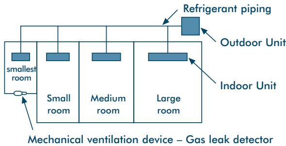
In a room where the density may exceed the limit, create an opening with adjacent rooms, or install mechanical ventilation combined with a gas leak detection device.
The density is:
Total amount of refrigerant (kg)
Min. volume of the Indoor Unit installed room (^3)
≤ Density limit (kg / m^3)
The density limit of R407C which is used in multi air conditioners is 0.15kg / m^3
Note 1:
If there are 2 or more refrigerating systems in a single refrigerating device, the amounts of refrigerant should be as charged in each independent device.
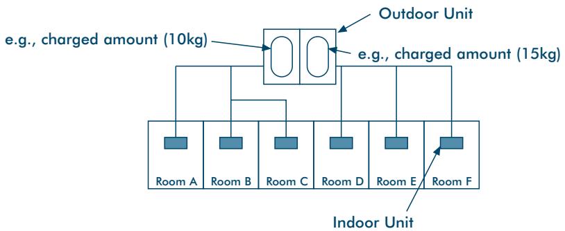
For the amount of charge in this example:
The possible amount of leaked refrigerant gas in rooms A, [B] and C is 10kg
The possible amount of leaked refrigerant gas in rooms D, E and F is 15kg .
Troubleshooting
Cautions On Refrigerant Leakage
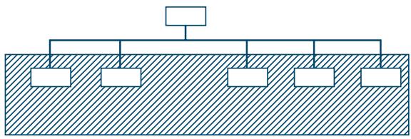
Note 2:
The standards for minimum room volume are as follows.
(1) No partition (shaded portion).
(2) When there is an effective opening with the adjacent room for ventilation of leaking refrigerant gas (i.e. an opening without a door, or an opening 0.15% or larger than the respective floor spaces at the top or bottom of the door).
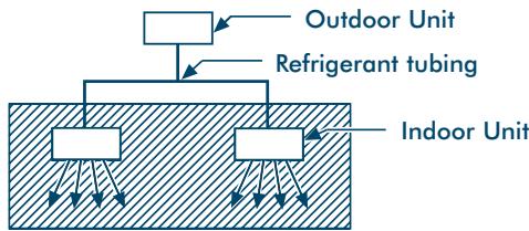
(3) If an Indoor Unit is installed in each partitioned room and the refrigerant piping is interconnected, the smallest room becomes the object. But when a mechanical ventilation is installed interlocked with a gas leakage detector in the smallest room where the density limit is exceeded, the volume of the next smallest room becomes the object.
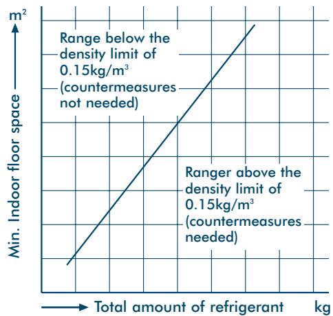
Note 3:
The minimum indoor floor space compared with the amount of refrigerant is roughly as shown:
(When the ceiling is 2.7m high)
Environmental
Precaution for Refrigerant Leakage
This air conditioning system contains HFC R407C refrigerant gas. We recommend that the installer should compare the total amount of refrigerant contained in the system with the air volume of each of the rooms in which an indoor unit has been installed. This practice is of

particular importance when installing a system with a large refrigerant volume. Using these figures, calculate the worst case refrigerant density (using the total refrigerant charge) in the unlikely event of a leak. If the resultant density level exceeds that of the standard, then either a ventilation system or alarm system, or both, must be installed. The above procedure must be completed in accordance with local, national and international standards, codes of practice and statutory requirements.
Product Maintenance
To minimise the chances of environmental damage and to ensure the efficient operation of the unit, it is recommended to have the air conditioner periodically checked and serviced by a qualified engineer.
Product disposal
Please dispose of the air conditioner unit in an environmentally responsible manner. Recycling is the preferred disposal method.
When disposing of an air conditioner system, contact either the manufacturer, your local environmental control authority or a local waste disposal company for advice.
Ensure all packaging material is either recycled or disposed of in accordance with local regulations.
The refrigerant gas within the unit should only be removed by an authorised company.
WARNING: Discharge of refrigerant to atmosphere is illegal and may lead to prosecution.
TOSHIBA
Sommaire
Dimension de Tuyau Principal
Controll finally installation 287
4. Nominate condities
Koeling : Binnen temperatuur 27^ DB/19°C WB
(4 posities per installation)