SSD7140 - NAS Highpoint - Free user manual and instructions
Find the device manual for free SSD7140 Highpoint in PDF.

User questions about SSD7140 Highpoint
0 question about this device. Answer the ones you know or ask your own.
Ask a new question about this device
Download the instructions for your NAS in PDF format for free! Find your manual SSD7140 - Highpoint and take your electronic device back in hand. On this page are published all the documents necessary for the use of your device. SSD7140 by Highpoint.
USER MANUAL SSD7140 Highpoint
natural_image
Front view of a computer graphics card with two heat sinks and cooling fan array (no text or symbols visible)Quick Installation Guide
V1.06
System Requirements
PC Requirements
• System with a free PCIe3.0 (or 4.0) x16 slot
• Windows 10, Windows Server 2016 and Windows Server 2019
- Linux kernel 3.10 and later
• macOS 10.13 and later
SSD7140 Kit Content
• SSD7140 Controller Card
- Quick Installation Guide
SSD7140 Hardware
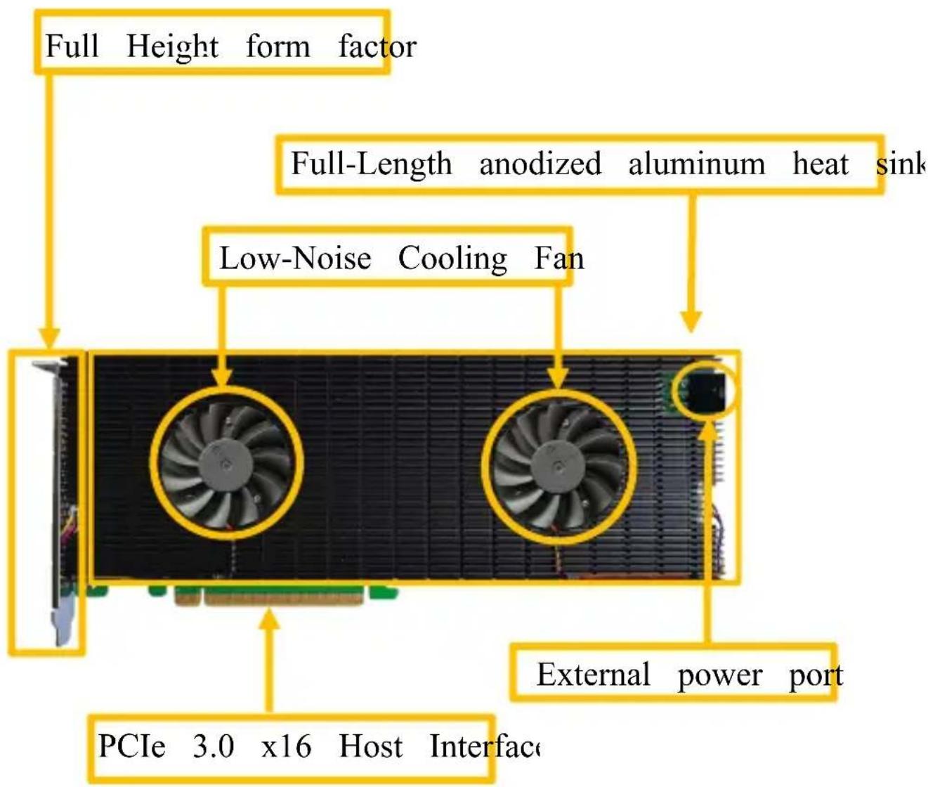
Front View
text_image
Full Height form factor Full-Length anodized aluminum heat sink Low-Noise Cooling Fan PCIe 3.0 x16 Host Interface External power portHardware Installation
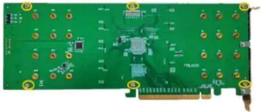
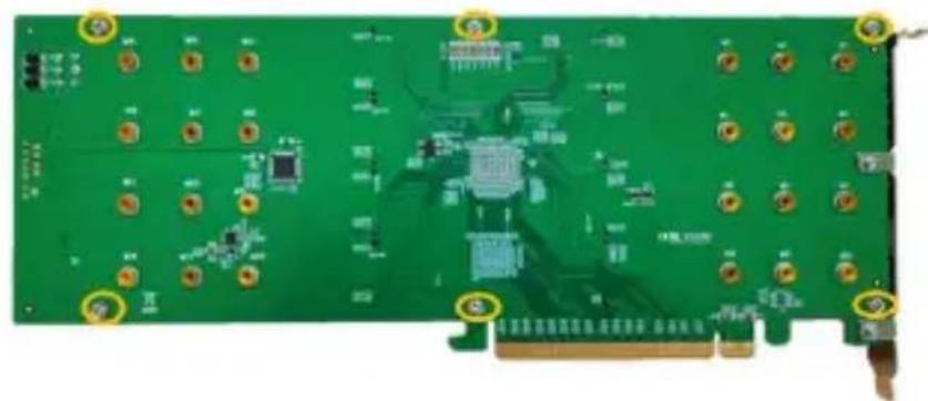
Step 1. On the rear of the SSD7140, remove the six screws tl the unit's heat sink to the PCB.
natural_image
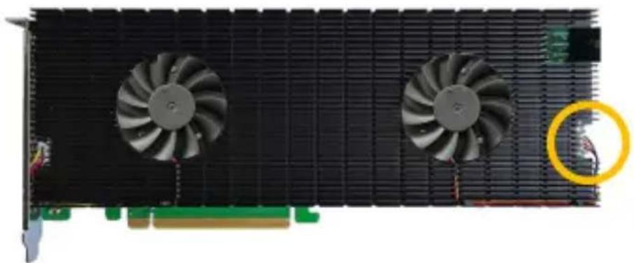
Green printed circuit board with multiple electronic components and mounting holes (no visible text or symbols)Step 2. Carefully remove fan's power cable from the right-side heatsink as shown below, then carefully flip the heatsink to left (like turning a page from a book).
Note: Take care when moving the heatsink to prevent dam the left fan's power cable.
natural_image
Front view of a black GPU card with two fans and a yellow circular annotation highlighting a component (no text or symbols)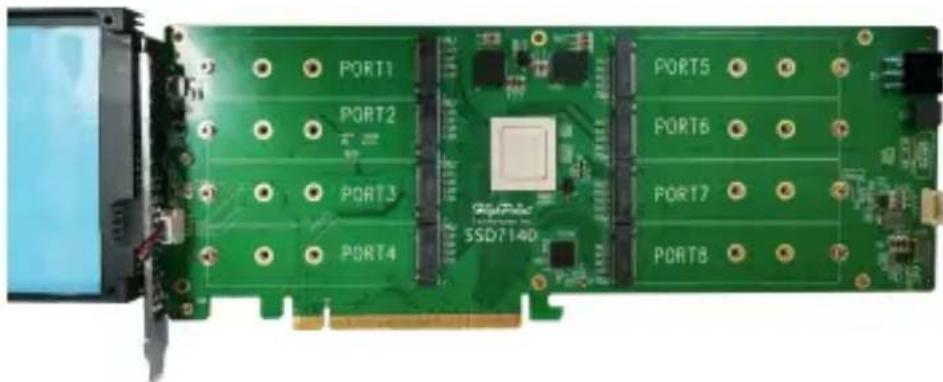
natural_image
Green PCI expansion card with labeled ports (PORT1–PORT8) and SSD7140 chip, no readable text or symbols beyond component labelsStep 3. After removing the casing, carefully turn it over to view thermal pad. The blue films must be removed from the pad before reinstalling the panel. These films protect the pad from damage foreign objects prior to installation, however, they will also prevent thermal pad from conducting the heat away from the NVMe SS we don't remove it.

text_image
Remove the Cover Before Use Remove the Cover Before UseStep 4. These 8 screws are used to install the NVMe SSD's.
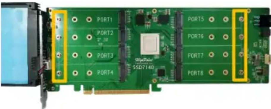
text_image
PORT1 PORT2 PORT3 PORT4 32-Peel SSD7140 PORT5 PORT6 PORT7 PORT8Step 5. Please remove these screws from each of the M.2 slots
text_image
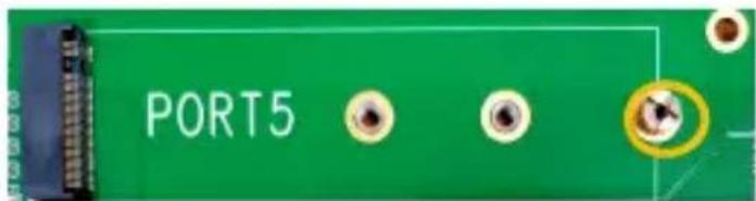
PORT5Step 6. Gently insert the SSD into the slot.

natural_image
Green circuit board with black display and control panel (no visible text or symbols)Note: Please make sure all disks are clean before you ins into the slot to avoid unexpected situations.
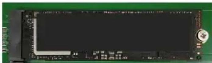
Step 7. Refasten the screw to secure the SSD.
natural_image
Green circuit board with a black LCD screen and a small circular component (no visible text or symbols)Repeat Steps 4 to 6 to install the remaining SSDs.
The following example shows eight M.2 NVMe SSDs installed in Ports 1-8:

natural_image
Green PCI card with multiple RAM slots and a central chip, no visible text or symbols on the card surface.Step 8. After installing all SSDs, carefully flip the heatsink to
Note: Make sure each SSD is carefully aligned and fastene SSD7140 using the supplied screws. Loosely attached SSDs not be detected by the SSD7140 or host system.
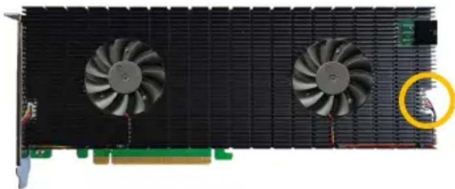
Step 9. Carefully reinsert in the power supply cable of the coo that was removed in step 2.
natural_image
Front view of a computer graphics card with two fans and a highlighted cable (no text or symbols visible)Step 10. On the rear of the SSD7140, refasten the 6 screws tl removed in step 1.
natural_image
Green printed circuit board with multiple electronic components and mounting holes (no visible text or symbols)Note: Make sure the aluminum cover is properly aligned with controller board (PCB), and that it makes full contact with thermal pad, before refastening it to the SSD7140. If the improperly installed, the fan and thermal pad will be unable sufficiently cool the NVMe SSD's and controller componentry which may result in damage to the SSD's or controller has performance loss, unstable I/O, and the loss of data.
Step 11. Power up the SSD external power supply
Note: If the external power supply is not powered on, the
may drop offline or remain undetected, which could lead to loss.

natural_image
Close-up of a computer hardware component with two cooling fans and a cable connector (no visible text or symbols)SSD7140 relies on two power sources to support eight SSI power supplied through the PCIe bus, and power from the system's PSU via an external 6 pin PCIe power cable. If external cable is not connected, there will be insufficient p support all 8 SSD's; this may cause the SSDs to drop of
Note: The SSD7140 does not require the external power cc when used with 2019 Mac pro systems.

text_image
Connect 6 pin PCIe power cable 9Note: Please be sure to connect NVMe before using the product reduce the occurrence of unnecessary errors!
Note: Install the driver in the system first and then install the
Resources
A variety of manuals, guides and FAQ's are available for the RAID controller.
In addition, we recommend visiting the Software Downloads web for the latest drivers, management interfaces, and installation guid
Software Download:
SSD7140 Driver, WebGUI, Installation Guides
https://highpoint-tech.com/USA_new/series-ssd7140-download.htm
Other Reference Information:
Mother Board & NVMe SSD Compatibility List
SSD7140 User Guides
https://highpoint-tech.com/USA_new/series-ssd7140-resource.htm
Customer Support
If you encounter any problems while utilizing the SSD7140, or any questions about this or any other HighPoint Technologies, In product, feel free to contact our Customer Support Department.
Web Support:
https://www.highpoint-tech.com/websupport/main.php
HighPoint Technologies, Inc. websites:
https://www.highpoint-tech.com
© Copyright 2021 HighPoint Technologies, Inc. All rights re