OR-841-HDSDI - Suivi MARSHALL - Free user manual and instructions
Find the device manual for free OR-841-HDSDI MARSHALL in PDF.

User questions about OR-841-HDSDI MARSHALL
0 question about this device. Answer the ones you know or ask your own.
Ask a new question about this device
Download the instructions for your Suivi in PDF format for free! Find your manual OR-841-HDSDI - MARSHALL and take your electronic device back in hand. On this page are published all the documents necessary for the use of your device. OR-841-HDSDI by MARSHALL.
USER MANUAL OR-841-HDSDI MARSHALL
Marshall Electronics

orchid OR-841-HDSDI
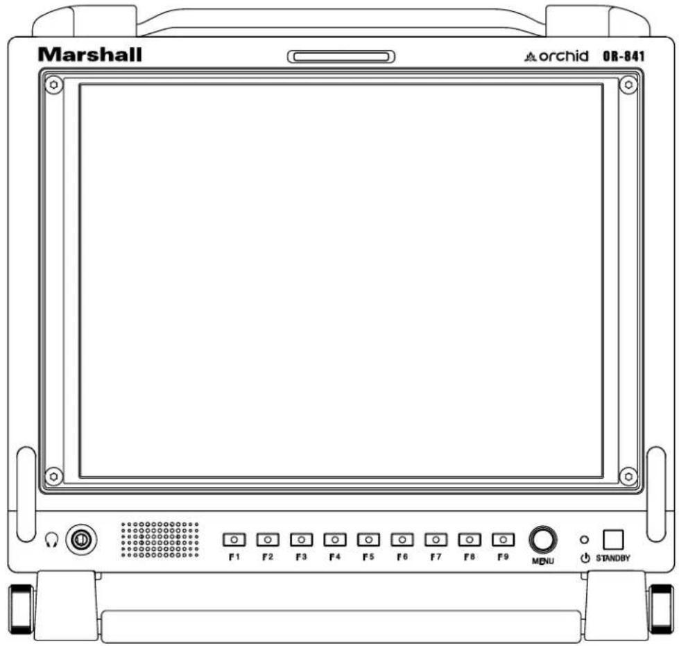
Fully Featured 8.4" Rack Mountable / Camera-Top / Portable LCD Field Monitor
text_image
Marshall orchid OR-841 F1 F2 F3 F4 F5 F6 F7 F8 F9 MENU STANDBYOperating Instructions
Contents
Product Overview 3
Features....3
Installation and Initial Setup .... 5
Unpacking....5
Mounting....5
Connections and Power-On....5
Front Panel Features....6
Power Button....6
Input Select Buttons....6
User-Definable Function Buttons 6
Image Adjustment Knobs....6
Rear Panel Features 7
Power Input 7
Compatible Input Formats....8
On-Screen Menu 9
MAIN MENU AND NAVIGATION 12
INFO SUBMENU....12
INPUT SUBMENU 12
PICTURE SUBMENU....13
COLOR SUBMENU 13
Color Temperature Presets 13
RGB Bias and Gain....13
SCREEN SUBMENU 14
Scan....14
Aspect Ratio Setting 14
Mono / Color....14
H/V Delay....14
Shift H 14
Shift V 15
MARKER CONFIGURATION SUBMENU....15
Markers 15
Center Marker....15
Aspect Markers 15
Safety Marker 15
Marker Mat 15
Line Thickness....15
Line Type 15
AUDIO CONFIGURATION SUBMENU....16
Meter Background....16
Display Channels 16
Active Channel Only 16
Meter Columns....16
Display Type....16
Front Volume 16
Rear Volume 16
Headroom Start 16
Headroom End 16
Channel Assignment....16
Load CH Preset....16
Save CH Preset 17
CH Preset 17
WAVEFORM SUBMENU 17
VECTORSCOPE SUBMENU 18
ClipGuide SUBMENU 18
USER ASSIGN SUBMENU 19
REMOTE SUBMENU 20
SETUP SUBMENU 20
Specifications 22
Maintenance / Color Calibration Procedure....23
Warranty Information 24
Product Overview
The Orchid OR-841-HDSDI is a single 8.4" fully featured camera-top and field monitor system. The OR-841-HDSDI offers built-in Waveform Monitor, Vectorscope, Audio Bars, Built In Speaker with audio outputs, and several diagnostic tools. This monitor is ideal for use as a camera top or field camera assist monitor. The OR-841-HDSDI is equipped with two HD/SD-SDI inputs with switched output. Diagnostic tools include our exclusive ClipGuide feature, 16 Tri-Color Audio Bar Graph meters with peak hold and numeric display of headroom and peak levels, and real-time analysis of color space conversion gamut errors. Other standard features include factory calibrated screen, easy-to-navigate onscreen menus with RotoMenu control, 9 assignable function keys, adjustable color temperature, aspect ratio settings, a variety of screen markers, blue-only mode, monochrome mode, H/V delay, and 7 assignable GPI inputs.
Features
High Resolution 8.4" Panel
The OR-841-HDSDI features an all-digital TFT-MegaPixel active matrix LCD system. The LCD panel features a nominal brightness of 400 cd/m^2 and a contrast ratio of 400:1 making each display ideal in a variety of environments and lighting conditions.
natural_image
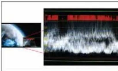
Composite image showing Earth and a waveform display (no readable text or symbols)Waveform monitor function
The built-in waveform monitor (which includes adjustable White and Black clip level indicators) can be displayed in various aspect ratios, positions, and transparency options. The Waveform Monitor not only monitors luminance, but can also warn the user for out-of-range conditions such as overexposure or “blacker-than-black” errors with fully user-adjustable warning limits.

natural_image
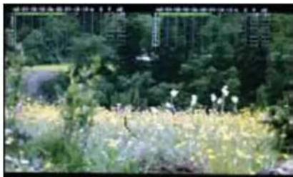
Landscape photo of a grassy field with scattered white flowers and green trees, featuring an inset image of a bird in flight (no text or symbols visible)Real-time Color Vectorscope
The built-in Vectorscope allows users to monitor color gamut range in real time. It displays in full color and can also be displayed in various sizes, positions, and transparency options. The Vectorscope has adjustable gain from 1x to 5x.

natural_image
Illustration of Earth from space showing cloud cover and atmospheric layers (no text or symbols)ClipGuide
The ClipGuide function operates with both the Waveform display and Monochrome/Color picture display. Both the upper and lower ClipGuide levels are user-adjustable in order to accurately display over-and-under exposures during different shooting conditions. For example, the upper ClipGuide limit may be set to 85 IRE and the lower limit to 10 IRE. With these settings, any exposures over the set limit of 85 IRE will display red on both the Waveform and picture (if selected). The same will be true for blacks under 10 IRE.
Chroma monitor function
Included in the ClipGuide menu are settings for monitoring color gamut errors, which can occur in color space conversion. Any data exceeding these values will be displayed as Yellow in the picture. The factory preset for C limits are 16 and 240 according to ITU-R BT.709. Typically, these values should not be exceeded during normal video production.
natural_image
Landscape photo of a green field with scattered white flowers and distant high-rise buildings (no visible text or symbols)Precision Audio Level Meters
De-embeds and displays up to 16 channels of audio using sixteen 64-segment tri-color Audio Meters with user-adjustable reference levels. The Audio Level Meters provide numerical indicators and headroom levels, as well as peak hold function. Audio Channel Loss Warning prevents errors during monitoring.
scatter
| x | y | | ------- | ------- | | 0.25704 | 0.25704 | | 0.25705 | 0.25705 | | 0.25706 | 0.25706 | | 0.25707 | 0.25707 | | 0.25708 | 0.25708 | | 0.25709 | 0.25709 | | 0.25710 | 0.25710 | | 0.25711 | 0.25711 | | 0.25712 | 0.25712 | | 0.25713 | 0.25713 | | 0.25714 | 0.25714 | | 0.25715 | 0.25715 | | 0.25716 | 0.25716 | | 0.25717 | 0.25717 | | 0.25718 | 0.25718 | | 0.25719 | 0.25719 | | 0.25720 | 0.25720 | | 0.25721 | 0.25721 | | 0.25722 | 0.25722 | | 0.25723 | 0.25723 | | 0.25724 | 0.25724 | | 0.25725 | 0.25725 | | 0.25726 | 0.25726 | | 0.25727 | 0.25727 | | 0.25728 | 0.25728 | | 0.25729 | 0.25729 | | 0.25730 | 0.25730 | | 0.25731 | 0.25731 | | 0.25732 | 0.25732 | | 0.25733 | 0.25733 | | 0.25734 | 0.25734 | | 0.25735 | 0.25735 | | 0.25736 | 0.25736 | | 0.25737 | 0.25737 | | 0.25738 | 0.25738 | | 0.25739 | 0.25739 | | 0.25740 | 0.25740 | | 0.25741 | 0.25741 | | 0.25742 | 0.25742 | | 0.25743 | 0.25743 | | 0.25744 | 0.25744 | | 0.25745 | 0.25745 | | 0.25746 | 0.25746 | | 0.25747 | 0.25747 | | 0.25748 | 0.25748 | | 0.25749 | 0.25749 | | 0.25750 | 0.25750 | | 0.25751 | 0.25751 | | 0.25752 | 0.25752 | | 0.25753 | 0.25753 | | 0.25754 | 0.25754 | | 0.25755 | 0.25755 | | 0.25756 | 0.25756 | | 0.25757 | 0.25757 | | 0.25758 | 0.25758 | | 0.25759 | 0.25759 | | 0.25760 | 0.25760 | | 0.25761 | 0.25761 | | 0.25762 | 0.25762 | | 0.25763 | 0.25763 | | 0.25764 | 0.25764 | | 0.25765 | 0.25765 | | 0.25766 | 0.25766 | | 0.25767 | 0.25767 | | 0.25768 | 0.25768 | | 0.25769 | 0.25769 | | 0.25770 | 0.25770 | | 0.25771 | 0.25771 | | 0.25772 | 0.25772 | | 0.25773 | 0.25773 | | 0.25774 | 0.25774 | | 0.25775 | 0.25775 | | 0.25776 | 0.25776 | | 0.25777 | 0.25777 | | 0.25778 | 0.25778 | | 0.25779 | 0.25779 | | 0.25780 | 0.25780 | | 0.25781 | 0.25781 | | 0.25782 | 0.25782 | | 0.25783 | 0.25783 | | 0.25784 | 0.25784 | | 0.25785 | 0.25785 | | 0.25786 | 0.25786 | | 0.25787 | 0.25787 | | 0.25788 | 0.25788 | | 0.25789 | 0.25789 | | 0.3489Precision White Balance with Color Temperature Adjustment
White balance adjustment is essential in order to render colors correctly. To display colors correctly, gray scale should maintain identical color temperature. The white balance for ORCHID monitors defaults to D65 (6500K) so the user does not need to adjust white balance.
LCD monitors have color-matching issues because white balance can be affected by a change in luminance level. Our unique color management system solves this problem.
The ORCHID operating system includes an Automatic White Balance function that allows a “One Button” calibration procedure when used with a Minolta CA-210 color probe. All Orchid Series LCD panels are calibrated at the factory to ensure color conformity between screens.
Select color temperature and gamma mode
Color temperature presets may be selected between D65 or D93 as well as user-defined settings. Gamma settings are adjustable from 1.0 to 3.0 in 0.1 steps. The standard setting is 2.2.
Flexible Screen Markers
A variety of screen markers in 4:3, 16:9, and full screen modes allow accurate monitoring of the different aspect ratios used in broadcast environments.
User-Definable Function Buttons
Nine user-definable function buttons and one Rotary Encoder on the front panel allow quick access to numerous settings and features including Input 1, Input 2, Option Input, Waveform, Vectorscope, Audio Bars, aspect ratio, screen markers, monochrome mode, H/V delay mode, and more.
AUDIO Jack
There are two 3.5mm AUDIO jacks (one on the front panel for headphones and one on rear panel to feed an external amplifier). It is possible to utilize both the front panel headphone connector and rear panel speaker connector simultaneously with individual volume controls. When not in menu mode, the rotary encoder on the front panel may control the headphone and internal speaker volume.
Installation and Initial Setup
Unpacking
Carefully unpack the OR-841-HDSDI monitor and verify that the following items are included:
• OR-841-HDSDI Monitor
• 12V 4A XLR Power Supply with 4-Pin Female XLR Connector
- Operating Instructions
Inspect the unit for any physical damage that may have occurred during shipping. Should there be any damage, immediately call Marshall Electronics Customer Service at (800) 800-6608. If you are not located within the continental United States, call +1 (310) 333-0606.
Mounting
The OR-841-HDSDI is designed as a tabletop camera assist or tri-pod/camera-top monitor. It comes complete with tabletop stand, easy-to-carry handle on top, and is equipped with both 14 -20 and 3/8" threaded mounts on top and bottom. The included handle and stand may be removed for access to the threaded mounts.
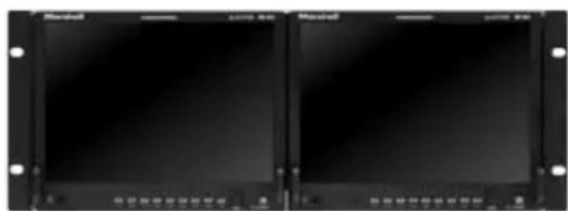
There is an optional OR-8RK rack mount kit for mounting two OR-841-HDSDI units side by side in a standard 19" rack. When used in this configuration, the Dual OR-841-HDSDI units occupy 5 RU and have a +/- 40° Tilt.
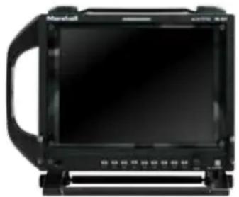
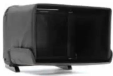
Other optional accessories include the OR-8HO Custom Hood for daylight viewing and the OR-8HA optional side mount handle. One handle may be mounted on each side of the OR-841 for easy carrying during a wireless camera shoot.
Optional Accessories for OR-841
natural_image
Front view of a black electronic device with a screen and handle (no visible text or symbols)OR-8HA Side Handle
natural_image
Black rectangular electronic device with a flat top and side panel (no visible text or symbols)OR-8HO Hood
natural_image
Two black rectangular electronic equipment units with mounting holes, no visible text or symbols on the surfaces.OR-8RK Rack Mount Kit (Mounts two units side-by-side)
Connections and Power-On
Plug the power supply into an AC power source (100-240 V @ 50/60 Hz). Attach the 4-pin female XLR connector to the back of the monitor. The monitor will draw no more than 4.0 Amps at 12 Volts in operation (24 Watts).
Connect the required cables for video signal input and output (Power must be applied to the OR-841-HDSDI for the active loop-through outputs to be activated). All BNC connectors are rated at 75Ω.
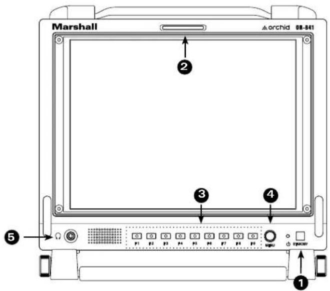
Front Panel Features
text_image
Marshall archid 08-041 ② ③ ④ ⑤ ①1 Power Button with Indicator
Press power switch to turn on the Unit. The indicator LED will turn Green. Press again to put the OR-841-HDSDI into standby mode. The LED will turn Red.
② Tri-Color Tally Light
30mm Tri-Color tally lamp controlled via the Remote connector on the rear of the unit.
3 User-Definable Function Keys
Nine user-definable function buttons can be used for direct access to various settings. Functions are assigned using the on-screen menu.
4 User-Defined Rotary Encoder
The Rotary Encoder may be assigned to one of five functions through the User Assign menu. The available functions are:
- Volume
- Brightness
- Contrast
- Saturation
- Sharpness
Turning the encoder will allow the user to make adjustments to the selected mode.
ROTOMENU Control
Press the ROTOMENU Encoder to access the on-screen Menu. Turn the encoder to the Left or Right to navigate Up and Down on the on-screen menu. Press the encoder to select the sub-menu. When you arrive at the sub-menu or value you wish to modify, turn the encoder to select the new value and then press the Encoder to save the change. If you exit the data entry submenu before pressing the Encoder, the changes will not be saved. You may exit sub-menus by turning the Encoder to the Return heading and pressing the Encoder to select, or simply by pressing the F9 key.
5 Headphone Jack
3.5mm stereo headphone jack. Left and Right source are selected from the on-screen menu.
Rear Panel Features
Parallel Remote RJ-45 Pin Assignments
| Pin 1 | GPI 1 |
| Pin 2 | GPI 2 |
| Pin 3 | GPI 3 |
| Pin 4 | GPI 4 |
| Pin 5 | GND |
| Pin 6 | GPI 5 |
| Pin 7 | GPI 6 |
| Pin 8 | GPI 7 |
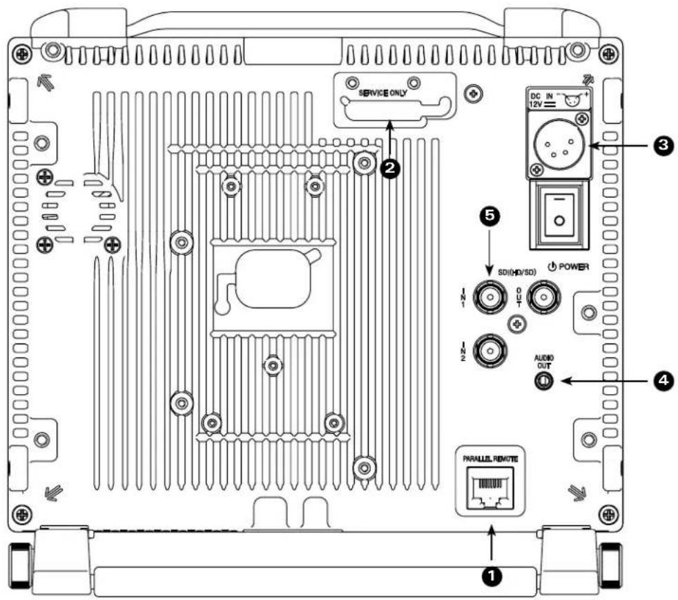
text_image
SERVICE ONLY DC IN 12V SD(HD/SD) POWER IN1 OUT IN2 AUDIO OUT PARALLEL REMOTE 1 2 3 41 GPI Input
RJ-45 connector for 7 user-assignable GPI inputs. Assignable using the on-screen menu.
② Service Port
Proprietary connection used for firmware upgrades and LCD color balance calibration.
3 Power Input
Connect 12VDC to the 4-Pin XLR power input connector. Power can be supplied from the included power supply or from a variety of DC sources supplying at least 1 Amp at 12 Volts.
IMPORTANT: If using a power source other than the included power supply, be sure that the polarity of the DC input is correct:
Pin 1: GND
Pin 2: N/C
Pin 3: N/C
Pin 4: +12VDC
4 Audio Output
3.5mm stereo line level output for monitoring embedded audio channels. The desired audio channels are selected in the Audio onscreen menu. The output level is also controlled through the Audio onscreen menu.
5 Video input connectors
Dual Auto-Sensing HDSDI BNC Video inputs. There are two HDSDI video inputs.
Each input auto-detects HD and SD-SDI video signals.
The output connector is an active re-clocked video signal from the selected HD/SDI input.
OR-841-HDSDI Compatible Formats
| Format HD/SD-SDI | |
| 480 / 60i | √ |
| 576 / 50i | √ |
| 480 / 60p | |
| 576 / 50p | |
| 720 / 60p | √ |
| 720 / 50p | √ |
| 720 / 30p | √ |
| 720 / 25 | √ |
| 720 / 24p | √ |
| 1080 / 60p | |
| 1080 / 50p | |
| 1080 / 60i (30PsF) | √ |
| 1080 / 50i (25PsF) | √ |
| 1080 / 48i (24Psf) | √ |
| 1080 / 30p | √ |
| 1080 / 25p | √ |
| 1080 / 24p | √ |
| VGA | |
| SVGA | |
| XGA | |
| SXGA | |
| UXGA | |
| WUXGA | |
On-Screen Menu
| OR-841-HDSDI MENU STRUCTURE OVERVIEW | ||
| INFO [1080i / 60] | MODEL NAME OR-841-HDSDI | |
| OPTION CARD N/A | ||
| OPTION S/N | ||
| INPUT SDI | ||
| INPUT FORMAT 1080i / 60 | ||
| COLOR MATRIX 709 | ||
| COLOR TEMP D65 | ||
| VERSION 0.0.0.0 | ||
| INPUT [SDI] | RETURN | |
| INPUT SELECT SDI 1 / SDI 2 | ||
| Analog Calibrate > | ||
| PICTURE | RETURN | |
| BRIGHT 0~100 [50] is Calibrated setting | ||
| CONTRAST 0~100 [80] is Calibrated setting | ||
| SATURATION 0~100 [50] is Calibrated setting | ||
| SHARPNESS 0~100 [0] is Calibrated setting | ||
| GAMMA | 1.0 to 3.0 in 0.1 steps [2.2] is Calibrated Setting | |
| COLOR [D65 / 709] | RETURN | |
| COLOR MATRIX AUTO, RGB, BT. 601, BT. 709 | ||
| COLOR TEMP CIE D65, JP D93, USER, CAL D65/D93, CAL D65, CAL D93 | ||
| RED BIAS | -128 to 127 [0] is Calibrated Setting | |
| GREEN BIAS | -128 to 127 [0] is Calibrated Setting | |
| BLUE BIAS | -128 to 127 [0] is Calibrated Setting | |
| RED GAIN | 0.000 to 1.992 [x1.00] is Calibrated setting | |
| GREEN GAIN | 0.000 to 1.992 [x1.00] is Calibrated setting | |
| BLUE GAIN | 0.000 to 1.992 [x1.00] is Calibrated setting | |
| SCREEN [16 : 9] | RETURN | |
| SCAN | NORMAL, OVERSCAN, ZOOM | |
| ASPECT AUTO, 4:3, 16:9 | ||
| MONO COLOR SEL | RGB | |
| MONO | ||
| RED | ||
| GREEN | ||
| BLUE | ||
| R+G | ||
| R+B | ||
| G+B | ||
| H/V DELAY | ON / OFF | |
| SHIFT II -128 to 127 [0] is Calibrated Setting (- = Right) | ||
| SHIFT V -128 to 127 [0] is Calibrated Setting (- = Down) | ||
| MARKER | RETURN | |
| MARKER | ON / OFF | |
| CENTER | ON / OFF | |
| ASPECT RATIO | OFF | |
| 4:03 | ||
| 16:9 | ||
| 1.85:1 | ||
| 2.35:1 | ||
| 4:3 & 2.85:1 | ||
| 4:3 & 2.35:1 | ||
| SAFETY ZONE | 80% to 100% (OFF) [95%] is normal setting | |
| MARKER MAT | CLEAR, HALFTONE, BLACK | |
| LINE THICKNESS | 1, 2, 3 | |
| LINE LEVEL GRAY, HALFTONE, WHITE, INVERT | ||
| AUDIO [ON] | RETURN | |
| LEVEL METER ON / OFF | ||
| METER BACKGROUND ON / OFF | ||
| DISPLAY CHANNELS 1~16 | ||
| ACTIVE CH ONLY ACTIVE, ALL | ||
| METER COLUMNS DUAL, QUAD | ||
| DISP TYPE OVERLAP, OVERLAY | ||
| FRONT VOLUME 0 to 40 | ||
| REAR VOLUME 0 to 40 | ||
| HEADROOM START -6 to -60 | [-20] is SMPTE Standard | |
| HEADROOM END 0 to -20 [-6] is Normal setting | ||
| LEFT CHANNEL CHANNEL1 | TO CHANNEL 16 | |
| RIGHT CHANNEL CHANNEL1 | TO CHANNEL 16 | |
| LOAD CH PRESET FROM > PRESET 1 to PRESET 8 | ||
| SAVE CH PRESET TO > | PRESET 1 to PRESET 8 | |
| CH PRESET | LOCK / UNLOCK | |
| WAVEFORM [ON] | RETURN | |
| LAYOUT | NORMAL, LAYOUT A, LAYOUT B | |
| WAVEFORM | ON / OFF | |
| SIZE | SMALL, MEDIUM, LARGE | |
| POSITION | LEFT TOP, LEFT BOTTOM, RIGHT TO, RIGHT BOTTOM | |
| TYPE | OVERLAY / OVERLAP | |
| Y OVER LIMIT | [100.0%] % IRE 0% to 109.1% | |
| Y UNDER LIMIT [100.0%] % IRE -7.3% to 109.1% | ||
| VECTORSCOPE | RETURN | |
| LAYOUT | NORMAL, LAYOUT A, LAYOUT B | |
| VECTORSCOPE | ON / OFF | |
| SIZE | SMALL, MEDIUM, LARGE | |
| POSITION | LEFT TOP, LEFT BOTTOM, RIGHT TOP, RIGHT BOTTOM | |
| TYPE | OVERLAY / OVERLAP | |
| GAIN | X1.00 to X1.91 in .01 steps | |
| ClipGuide | RETURN | |
| ClipGuide | ON / OFF | |
| MODE | LUMA (Y) | |
| LUMA (Y) ON MONO | ||
| CIROMA (C) | ||
| CIROMA (C) ON MONO | ||
| Y & C | ||
| Y & C ON MONO | ||
| DISPLAY TYPE | ZEBRA / FILL | |
| Y UPPER LIMIT | [100.0%] % IRE -7.3% to 109.1% | |
| Y UNDER LIMIT [0.0%] % IRE -7.3% to 109.1% | ||
| C UPPER LIMIT | 0~255 [016 = 7.5 IRE, 235 = 100 IRE] | |
| C LOWER LIMIT | 0~255 [016 = 7.5 IRE, 235 = 100 IRE] | |
| USER ASSIGN | RETURN | |
| F-1 THRU F-9 | INPUT 1 | |
| INPUT 2 | ||
| GAMMA 1.0 | ||
| GAMMA 1.8 | ||
| GAMMA 2.0 | ||
| GAMMA 2.2 | ||
| GAMMA 2.4 | ||
| GAMMA 2.6 | ||
| WHITEBALANCE D65 | ||
| WHITEBALANCE D93 | ||
| MONO | ||
On-Screen Menu (continued)
| USER ASSIGN | F-1 THRU F-9 | COLOR CHANNEL AUDIO PRESET 5 | |
| SCAN AUDIO PRESET 6 | |||
| ASPECT AUDIO PRESET 7 | |||
| ZOOM AUDIO PRESET 8 | |||
| HV DELAY LAYOUT A | |||
| MARKER LAYOUT B | |||
| AUDIO METER WAVEFORM MON | |||
| AUDIO PRESET 1 VECTORSCOPE | |||
| AUDIO PRESET 2 ClipGuide | |||
| AUDIO PRESET 3 TIMECODE | |||
| AUDIO PRESET 4 | |||
| ROTARY 1 | VOLUME | ||
| BRIGHIT | |||
| CONTRAST | |||
| SATURATION | |||
| SHARPNESS | |||
| REMOTE | RETURN | ||
| PIN 1 THRU 8(Pin 5 is Ground) | INPUT 1 | ||
| INPUT 2 | |||
| GAMMA 1.0 | |||
| GAMMA 1.8 | |||
| GAMMA 2.0 | |||
| GAMMA 2.2 | |||
| GAMMA 2.4 | |||
| GAMMA 2.6 | |||
| WHITEBLANCE D65 | |||
| WHITEBALANCE D93 | |||
| MONO | |||
| SCAN | |||
| ASPECT | |||
| ZOOM | |||
| HV DELAY | |||
| RED ONLY | |||
| BLUE ONLY | |||
| GREEN ONLY | |||
| MARKER | |||
| AUDIO METER | |||
| AUDIO PRESET 1 | |||
| AUDIO PRESET 2 | |||
| AUDIO PRESET 3 | |||
| AUDIO PRESET 4 | |||
| AUDIO PRESET 5 | |||
| AUDIO PRESET 6 | |||
| AUDIO PRESET 7 | |||
| AUDIO PRESET 8 | |||
| LAYOUT A | |||
| LAYOUT B | |||
| WAVEFORM MON | |||
| VECTORSCOPE | |||
| CLIPGUIDE | |||
| TIMECODE LTC | |||
| TIMECODE VITC 1 | |||
| TIMECODE VITC 2 | |||
On-Screen Menu (continued)
| REMOTE | PIN 1 THRU 8(Pin 5 is Ground) | R TALLY |
| G TALLY | ||
| B TALLY | ||
| LEFT R TALLY | ||
| LEFT G TALLY | ||
| LEFT B TALLY | ||
| RIGHT R TALLY | ||
| RIGHT G TALLY | ||
| RIGHT B TALLY | ||
| SETUP | RETURN | |
| FORMAT DISP AUTO / ON / OFF | ||
| TIMECODE OFF / LITC / VITC1 / VITC2 | ||
| POWER SAVE | ALWAYS ON | |
| 2 MIN | ||
| 5 MIN | ||
| 10 MIN | ||
| 30 MIN | ||
| 1 HOUR | ||
| 2 HOUR | ||
| KEY LOCK LOCK / UNLOCK | ||
| RESET TO MFG DEFAULT > | REST NOW / CANCEL | |
| BACKUP USER CONFIG > | BACKUP NOW / CANCEL | |
| RESTORE USER CONFIG RE | STORE NOW / CANCEL | |
Main Menu and Navigation
Access the main menu by pushing the center MENU button on the front panel of the monitor.
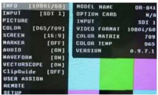
text_image
INFO [1080i/69] INPUT [SDI 1] PICTURE COLOR [D65/709] SCREEN [16:9] MARKER [OFF] AUDIO [ON] MAVEFORM [ON] VECTORSCOPE [ON] ClipGuide [OFF] USER ASSIGN REMOTE SETUP MODEL NAME OR-B41 OPTION CARD N/A INPUT SDI 1 VIDEO FORMAT 1080i/60 COLOR MATRIX 709 COLOR TEMP D65 VERSION 0.9.7.1- Step through menu items by using the RotoMenu control.
- Choose a submenu or select a menu item by pushing the RotoMenu control.
- Return to the previous menu by pressing the F-9 button.
- Exit the main menu by again pressing the F-9 button.
text_image
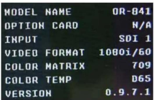
MODEL NAME OR-841 OPTION CARD N/A INPUT SDI 1 VIDEO FORMAT 1080i/60 COLOR MATRIX 709 COLOR TEMP D65 VERSION 0.9.7.1INFO SUBMENU
The INFO Submenu is a read-only display that gives the user information about the particular screen being viewed. No adjustment can be made from this submenu.
INPUT SUBMENU
The Input sub menu allows the user to select either the SDI-1 / SDI-2 inputs or the Optional Input module if installed as the source to be displayed.
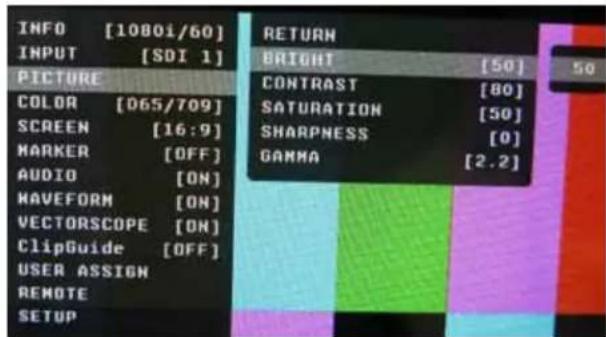
PICTURE SUBMENU
The Picture submenu allows the user to make adjustments to Brightness, Contrast, Saturation, Sharpness and Gamma.
Brightness
- Varies between 0 and 100 (50 is standard).
- 50 is default value with standard black level.
- Increasing brightness level allows user to see BTB (Blacker-than-Black).
Contrast
- Varies between 0 and 100 (80 is standard).
- 80 is default value with 100% gain of video signal.
Saturation
- Varies between 0 and 100 (50 is standard).
- 50 is default value with nominal color saturation.
- Setting to 0 should display as monochrome.
- Increasing value will increase color saturation.
Sharpness
- Varies between 0 and 100 (0 is standard).
- 0 is default value with no scaling artifact.
Gamma
- Varies between 1.0 and 3.0 with 0.1 steps.
- If White Balance is set to User Mode, changing gamma will have no effect.
text_image
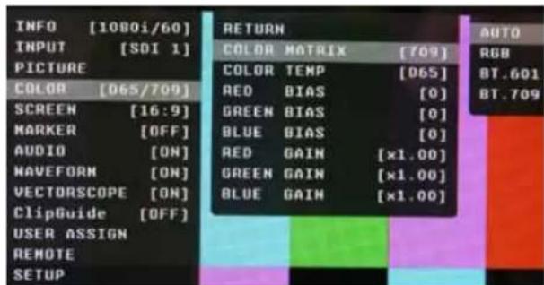
INFO [1080i/60] INPUT [SDI 1] PICTURE COLOR [065/709] SCREEN [16:9] MARKER [OFF] AUDIO [ON] HAVEFORM [ON] VECTORSCOPE [ON] ClipGuide [OFF] USER ASSIGN REMOTE SETUP RETURN BRIGHT [50] CONTRAST [80] SATURATION [50] SHARPNESS [0] GAMMA [2.2]COLOR SUBMENU
The Color submenu allows the user to access to the Color management controls.
■ Color Matrix
Auto
- System automatically selects correct matrix.
• Typically, 601 for SD Formats, 709 for HD Formats.
RGB
- User can manually set to RGB.
- RGB should be used with GBR422 systems.
601
- Conforms to ITU-R BT.601 matrix.
709
- Conforms to ITU-R BT.709 matrix.
text_image
INFO [1080i/60] INPUT [SDI 1] PICTURE COLOR [065/709] SCREEN [16:9] MARKER [OFF] AUDIO [ON] MAVEFORM [ON] VECTORSCOPE [ON] ClipGuide [OFF] USER ASSIGN REMOTE SETUP RETURN COLOR MATRIX [709] COLOR TEMP [065] RED BIAS [0] GREEN BIAS [0] BLUE BIAS [0] RED GAIN [×1.00] GREEN GAIN [×1.00] BLUE GAIN [×1.00] AUTO RGB BT.601 BT.709■ Color Temp
Use this setting to choose between color temperature presets:
- D65 (6500K). Conforms to CIE D65 White Point. x = 0.3127, y = 0.3290
- D93 (9300K). Conforms to Japanese D93 White Point. x = 0.2830, y = 0.2980
- USER (Adjustable Color Bias and Gain)
• CAL D65/D93
• CAL D65
• CAL D93
■ RGB Bias and Gain
Select this submenu to fine-tune the monitor's color balance (R, G, B) or execute the One Button Auto White Balance function. The color calibration procedure is described at the rear of this manual. Fine-tuning the monitor's color balance (R, G, B) should only be done by someone experienced with video engineering, as this will alter the overall color shading of the screen. The purpose is to allow color matching to other types of monitors and/or displays. NOTE: The Color Temperature preset will automatically switch to CUSTOM when Color Bias or Gain settings are adjusted. It is normal for color bias adjustments to be very subtle. When selecting the RGB Bias and Gain submenus, changes to Gain and Bias will be seen in real time. Once the proper level is achieved, the user must save this setting by pressing the RotoMenu encoder. If the user leaves the setting menu before saving, the value will return to the original setting.
text_image
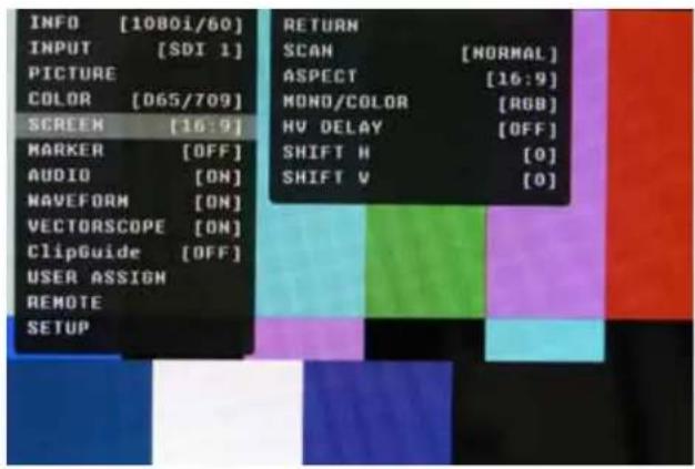
INFO [1080i/60] INPUT [SDI 1] PICTURE COLOR [D65/709] SCREEN [16:9] MARKER [OFF] AUDIO [ON] WAVEFORM [ON] VECTORSCOPE [ON] ClipGuide [OFF] USER ASSIGN REMOTE SETUP RETURN SCAN [NORMAL] ASPECT [16:9] MONO/COLOR [RGB] HV DELAY [OFF] SHIFT H [0] SHIFT V [0]SCREEN SUBMENU
■ Scan
Normal (Zero Scan)
- Whole picture should be visible without any cropping. - When in normal mode, it should not see non-active areas such as SAV, EAV.
Over (End-User TV Production Scan)
- 5% of the picture is cropped and zoomed to fill the screen. - After cropping, it will maintain correct aspect ratio and center.
Zoom
- When in zoom mode, the center portion of the picture is magnified to fill the screen by approximately 4x.
■ Aspect Ratio Settings
Use to switch between Full Screen, 4:3 and 16:9 aspect ratios.
The OR-841-HDSDI monitor has a native resolution of 1024 x 768 RGB pixels, so incoming images are automatically scaled to fit the screen:
- In Auto mode, images are displayed in their native Aspect Ratio. SD is normally 4:3 / HD normally 16:9.
- In 4:3 mode, images are scaled to fill the maximum 4:3 portion of the screen (1024 x 768), with black bars filling the remainder of the screen, regardless of its original format.
- In 16:9 mode, images are scaled to fill the maximum 16:9 portion of the screen (1024 x 576) regardless of its original format.

natural_image
Two black horizontal bars on white background, no text or symbols presentAUTO with 16:9 source
natural_image
Empty white square with black border (no text or symbols)4:3 Mode with 16:9 source or native 4:3 in AUTO mode.
■ Mono / Color
Use the Mono / Color modes for monitor calibration or to analyze individual color components of an image.
- RGB = displays all three colors (Normal display)
- Mono = displays as monochrome
• Red Channel = displays red channel only - Green Channel = displays green channel only
- Blue Channel = displays blue channel only
• R+G = Red + Green - R + B = Red + Blue
• G+B = Green + Blue
■ H/V Delay
Use this setting to enable H & V Delay
- In H & V Delay mode, both horizontal sync and vertical sync are delayed, resulting in both horizontal and vertical blanking periods being shown at the center of the screen.
■ Shift H
Use the RotoMenu control to change the value of this setting which will shift the picture horizontally. Negative values will move the picture Right, while Positive values will move the picture Left. [0] is center value.
■ Shift V
Use the RotoMenu control to change the value of this setting, which will shift the picture Vertically. Negative values will move the picture DOWN, while Positive values will move the picture UP.
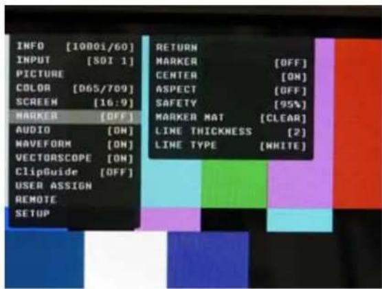
MARKER CONFIGURATION SUBMENU
Marker
Use this setting to enable or disable all on-screen markers. This setting affects the Center marker, Aspect markers, and Safety marker.
■ Center Marker
Use this setting to display a center marker on the screen.
■ Aspect Markers
Use these settings to superimpose one of 6 markers on the screen when in 16:9 mode.
• 4:3
• 16:9
• 1.85:1
• 2.35:1
• 4:3 and 1.85:1
• 4:3 and 2.35:1
text_image
INFO [1000i/60] INPUT [SOI 1] PICTURE COLOR [065/709] SCREEN [16:9] MARKER [OFF] AUDIO [ON] VAVEFORM [ON] VECTORASCOPE [ON] ClipGuide [OFF] USER ASSIGN REMOTE SETUP RETURN MARKER [OFF] CENTER [ON] ASPECT [OFF] SAFETY [95%] MARKER MAT [CLEAR] LINE THICKNESS [2] LINE TYPE [WHITE]■ Safety Marker
Use this setting to adjust the safety marker from 80% to 100% (Off) in 1% steps.
natural_image
Empty white rectangle with black border (no text or symbols)
natural_image
Empty rectangular frame with no text, symbols, or markingsOFF (No Marker) 2.35:1 Aspect Ratio 4:3 Aspect Ratio Marker 90% Safe Area
Marker Mat
Use this setting to change the format of the marker curtains between Clear, Halftone, or Black.
■ Line Thickness
Use this setting to choose the line thickness of the markers from 1, 2, or 3 pixels thick.
■ Line Type
Use this setting to select the style of line used for markers between White, Halftone, and Invert.
Example (80% Marker in 4:3 Mode):
natural_image
Empty rectangular frame with no text, numbers, or symbols inside
natural_image
Empty white rectangle with black border (no text or symbols)Normal Background Black Background
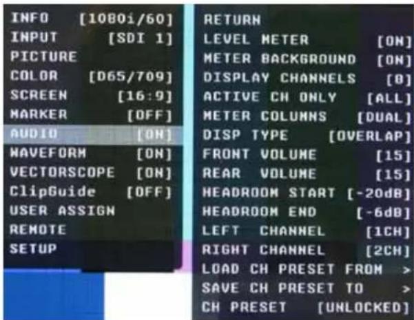
AUDIO CONFIGURATION SUBMENU
■ Level Meter
Selects whether or not to display audio level meters.
■ Meter Background
Selects whether or not to display meter background.
■ Display Channels
Selects how many audio meters you want to display. You may select any number of channels from 1 to 16.
■ Active Channel Only
Allows a choice of All channels or Active channels only. Selecting Active will override the Display Channels setting.
text_image
INFO [1080i/60] INPUT [SDI 1] PICTURE COLOR [D65/709] SCREEN [16:9] MARKER [OFF] AUDIO [ON] WAVEFORM [ON] VECTORSCOPE [ON] ClipGuide [OFF] USER ASSIGN REMOTE SETUP RETURN LEVEL METER [ON] METER BACKGROUND [ON] DISPLAY CHANNELS [O] ACTIVE CH ONLY [ALL] METER COLUMNS [DUAL] DISP TYPE [OVERLAP] FRONT VOLUME [15] REAR VOLUME [15] HEADROOM START [-20dB] HEADROOM END [-6dB] LEFT CHANNEL [1CH] RIGHT CHANNEL [2CH] LOAD CH PRESET FROM > SAVE CH PRESET TO > CH PRESET [UNLOCKED]■ Meter Columns
Allows a choice of displaying Level Meters is Dual (2) or Quad (4) columns.
■ Display Type
Allows a choice between Overlap and Overlay modes. Overlap is opaque and will block part of the video image where the Level Meters appear. Overlay is Halftone (semi-transparent) so video can be seen through the Level Meters.
■ Front Volume
Adjusts Headphone and speaker volume on the front panel. This value is adjustable from 0 to 40. Setting to 0 will Mute the output.
■ Rear Volume
Adjusts the Line Output jack on the rear panel. This value is adjustable from 0 to 40. Setting to 0 will Mute the output.
■ Headroom Start
Adjusts the point at which the level meters will change color from Green to Yellow. This is normally the level used for alignment. For digital audio in the US, the SMPTE standard is -20dBFS = 0VU = +4dBu. The European EBU standard is -18dBFS = 0VU. Other Alignment standards can be set using this menu.
■ Headroom End
Adjusts the point at which the level meters will change color from Yellow to Red. There is no official standard to where this point should occur. This is an arbitrary setting to give visual warning that the program level is peaking near the 0dBFS point at which there are no more bits and clipping will occur.
■ Left Channel / Right Channel
These menus are used to designate which one of the available 16 audio channels will be assigned to either the Left, Right, or both outputs for listening. For example, the user can choose to send CH 1 to the left output and CH 2 to the Right output, or the user can assign CH 1 to both Left and Right for a mono feed.
■ Load CH Preset From >
Use this menu to recall one of the 8 possible memory locations where the user previously stored channel output assignments. Use of this Load command will override the current channel output assignments.
■ Save CH Preset To >
Use this menu to select which one of 8 memory locations where the user wants to store the current channel output assignments.
■ CH Preset
Use this menu to Lock or Unlock the ability to save to the Ch Preset memory locations. This helps to prevent accidental overwriting of stored presets. When Locked, Ch Presets may still be recalled.
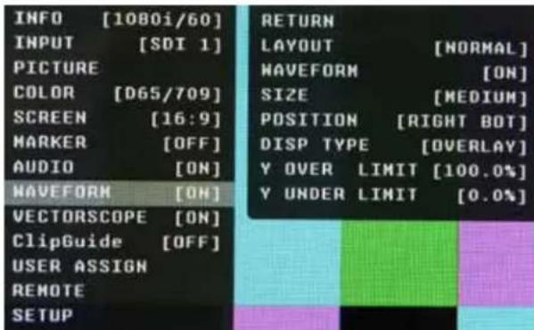
WAVEFORM SUBMENU
■ Layout
Use this menu to choose from several available preset screen layouts. Choosing any of the available preset layouts will override the settings in the Waveform, Size and Position menus.
■ Waveform
Use this menu to turn the Waveform display On or Off when in the Normal mode.
text_image
INFO [1080i/60] INPUT [SDI 1] PICTURE COLOR [D65/709] SCREEN [16:9] MARKER [OFF] AUDIO [ON] WAVEFORM [ON] VECTORSCOPE [ON] ClipGuide [OFF] USER ASSIGN REMOTE SETUP RETURN LAYOUT [NORMAL] WAVEFORM [ON] SIZE [MEDIUM] POSITION [RIGHT BOT] DISP TYPE [OVERLAY] Y OVER LIMIT [100.0%] Y UNDER LIMIT [0.0%]■ Size
Use this menu to choose the size of the Waveform display in Normal mode. Choices are Small, Medium, and Large.
■ Position
Use this menu to select the position you want the Waveform display to occupy on the screen when in the Normal mode. Choices are Left Top, Left Bottom, Right Top, and Right Bottom.
■ Display Type
Use this menu to choose how to display the waveform. The choices are Overlay or Overlap. In the Overlay mode, the waveform will be semi-transparent and the user will be able to see the source video through the waveform. In the Overlap mode, the waveform will be Opaque and will block the source video.
■ Y Over Limit
Use this menu to set where you want the waveform to display Red when the video source exceeds the limit set. This value is adjustable from -7.3% to 109.1% IRE. This setting is shared with the ClipGuide Menu.
■ Y Under Limit
Use this menu to set where you want the waveform to display Red when the video source below the limit set. This value is adjustable from -7.3% to 109.1% IRE. This setting is shared with the ClipGuide Menu.
Limits
- Internally, Y values ranges from 0 to 255.
- -7.3 IRE is equal to 0 in digital.
- 0 IRE is equal to 16 in digital.
• 100 IRE is equal to 235 in digital.
• 109.1 IRE is equal to 255 in digital
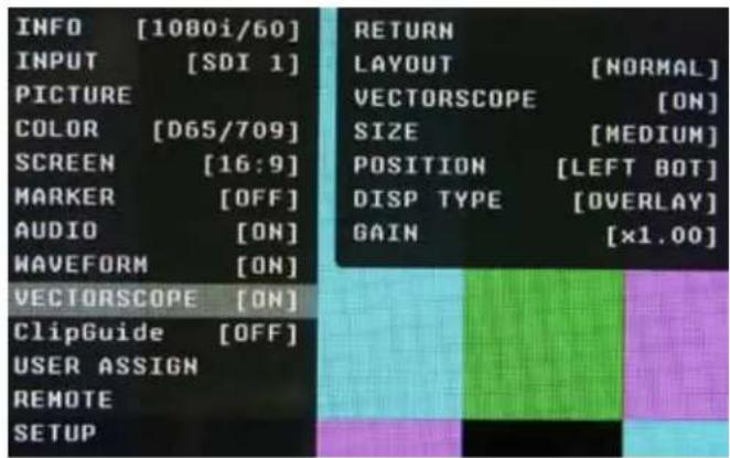
VECTORSCOPE SUBMENU
text_image
INFO [1080i/60] INPUT [SDI 1] PICTURE COLOR [D65/709] SCREEN [16:9] MARKER [OFF] AUDIO [ON] WAVEFORM [ON] VECTORSCOPE [ON] ClipGuide [OFF] USER ASSIGN REMOTE SETUP RETURN LAYOUT [NORMAL] VECTORSCOPE [ON] SIZE [MEDIUM] POSITION [LEFT BOT] DISP TYPE [OVERLAY] GAIN [x1.00]■ Layout
Use this menu to choose from several available preset screen layouts. Choosing any of the preset layouts will override the settings in the Vectorscope, Size, and Position menus.
■ Vectorscope
Use this menu to turn the Vectorscope display On or Off when in the Normal mode.
■ Size
Use this menu to choose the size of the Vectorscope display in Normal mode. Choices are Small, Medium, and Large.
■ Position
Use this menu to select the position you want the Vectorscope display to occupy on the screen when in the Normal mode. Choices are Left Top, Left Bottom, Right Top, and Right Bottom.
■ Display Type
Use this menu to choose how to display the Vectorscope. The choices are Overlay or Overlap. In the Overlay mode, the Vectorscope will be semi-transparent and the user will be able to see the source video through the Vectorscope. In the Overlap mode, the Vectorscope will be Opaque and will block the source video.
Gain
Use this menu to change the gain of the Vectorscope display. Normally, the Vectorscope displays x1.00. In order to allow a magnified view, the gain is adjustable from x1.00 to x4.98 in .01 steps. Changing this value has no effect on the source material.
ClipGuide SUBMENU
text_image
INFO [1080i/60] INPUT [SDI 1] PICTURE COLOR [D65/709] SCREEN [16:9] MARKER [OFF] AUDIO [ON] WAVEFORM [ON] VECTORSCOPE [ON] ClipGuide [OFF] USER ASSIGN REMOTE SETUP RETURN FORMAT DISPLAY [AUTO] TIMECODE [OFF] POWER SAVE [ALWAYS ON] KEY LOCK [UNLOCKED] RESET TO MFG DEFAULT BACKUP USER CONFIG > RESTORE USER CONFIG >■ ClipGuide
Use this menu to turn the ClipGuide function On or Off.
■ Mode
Allows the choice of which ClipGuide function you want to display. There are 6 modes to choose from:
• Luma (Y) displayed over Color video
• Luma (Y) displayed over Mono video
• Chroma (C) displayed over Color video
• Chroma (C) displayed over Mono video
• Luma (Y) and Chroma (C) displayed over Color Video
• Luma (Y) and Chroma (C) displayed over Mono Video
■ Display Type
ClipGuide will display over and under values in two ways when monitoring the video signal. In the Zebra mode, over and under conditions are indicated in a Zebra (diagonal stripe) pattern. In the Fill mode, over and under conditions are indicated by a solid fill. In either Zebra or Fill mode, Red is the indication for Luma and Yellow is the indication for Chroma.
Y Limits (These values are shared with WFM settings)
Set luminance upper and lower limits to be monitored.
- Limits are displayed in IRE unit
• Varies between -7.3 IRE and 109.1 IRE
• This value will be shown in WFM window as red line - Any data exceeding these values will be displayed as red on the picture
• These values are shared with WFM settings - Internally, Y values ranges from 0 to 255
- -7.3 IRE equals to 0 in digital
• 0 IRE equals to 16 in digital
• 100 IRE equals to 235 in digital
• 109.1 IRE equals to 255 in digital
C Limits
Sets the chrominance levels to be monitored.
• Displayed in 8-bit digital video representation
- Any data exceeding these values will be displayed as Yellow in the picture
• The factory preset for C limits are 16 and 240 according to ITU-R BT.709
• Typically these values should not be exceeded during normal video production
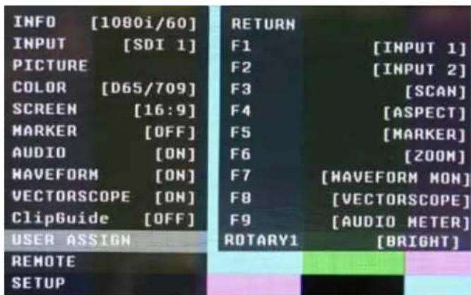
USER ASSIGN SUBMENU
■ F-1 thru F-9
There are nine Function Keys and One Rotary Encoder on the front panel of the OR-841-HDSDI. Each of these F-keys key may be assigned any one of 31 different functions as required by the job or individual user. The Rotary Encoder may be assigned in the same manner. These functions are listed in the Menu Overview section of this manual.
One-way functions
- Pressing pre-defined key will activate the feature
- When it is enabled, the indicator of the key will be lit up.
- Pressing again will have no effect. FOR EXAMPLE: Selecting Input, Selecting Audio Preset, Selecting White Balance
text_image
INFO [1080i/60] INPUT [SDI 1] PICTURE COLOR [D65/709] SCREEN [16:9] MARKER [OFF] AUDIO [ON] MAVEFORM [ON] VECTORSCOPE [ON] ClipGuide [OFF] USER ASSIGN RETURN F1 [INPUT 1] F2 [INPUT 2] F3 [SCAN] F4 [ASPECT] F5 [MARKER] F6 [ZOOM] F7 [WAVEFORM MON] F8 [VECTORSCOPE] F9 [AUDIO METER] ROTARY1 [BRIGHT] REMOTE SETUPTwo-way functions
- Pressing pre-defined key will active the feature
- When it is enabled, the indicator of the key will turn on
- Pressing again will deactivate the feature.
FOR EXAMPLE: Scan, WFM, ALM, Layout, HV Delay
Sequential functions
- Pressing pre-defined key will rotate features in sequence.
FOR EXAMPLE: Timecode, Color Channel - TimeCode will change its state for OFF->LTC->VITC1->VITC2->OFF
- Color Channel will change its state for RGB->R Only->G Only ... -> RGB
text_image
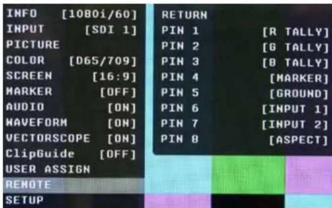
INFO [1080i/60] INPUT [SDI 1] PICTURE COLOR [D65/709] SCREEN [16:9] MARKER [OFF] AUDIO [ON] WAVEFORM [ON] VECTORSCOPE [ON] ClipGuide [OFF] USER ASSIGN REMOTE SETUP RETURN PIN 1 [R TALLY] PIN 2 [G TALLY] PIN 3 [B TALLY] PIN 4 [MARKER] PIN 5 [GROUND] PIN 6 [INPUT 1] PIN 7 [INPUT 2] PIN 8 [ASPECT]■ Pin 1 through Pin 8
The RJ-45 Remote connector on the rear panel has 8 pins. Pin 5 is Ground, while the remaining 7 pins are pulled high to 3.3VDC and may be used for Tally or other Remote Commands. A list of available Commands and Tally configurations can be found in the Menu Overview section of this manual. The command or Tally is activated by connecting the corresponding Pin (1-4 and 6-8) to Pin 5 (Ground).
Event Trigger
- Two types of events are allowed.
- The falling event is when you pull down to ground, and the rising event is when you remove the ground and the pin returns to normal high state.
- Falling events occurs only once and on the event of power up sequence.
- This means a falling event will occur only once regardless of whether its pin is repeatedly grounded such as when selecting an input source.
- The rising event can only occur once a pin has been pulled down to ground to activate the command such as turning on a tally releasing ground (open circuit) to turn off.
- Priority
- Lower pin number has higher priorities over higher pin numbers during power up sequence.
Tally System
Tally System can be used with non-separated mode and separated mode.
Non-separated mode
• Supports R/G/B tallies.
- Can mix any channels. FOR EXAMPLE: Mix Red and Green for Amber.
- Cannot mix R/G/B for White (It will be pink due to white balance).
- Cannot be assigned with separated tallies.
Left/Right Separated Mode
• Supports R/G/B tallies on each Left and Right.
- Can mix any channels for each Left and Right.
- Cannot mix R/G/B for White (It will be pink due to white balance).
- Cannot be assigned with non-separated tallies.
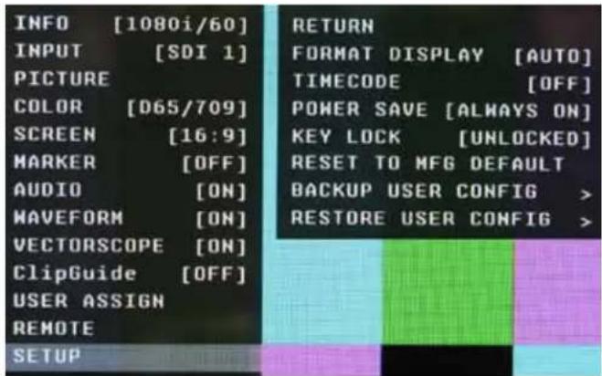
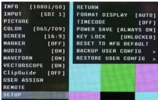
SETUP SUBMENU
text_image
INFO [1080i/60] INPUT [SDI 1] PICTURE COLOR [D65/709] SCREEN [16:9] MARKER [OFF] AUDIO [ON] WAVEFORM [ON] VECTORSCOPE [ON] ClipGuide [OFF] USER ASSIGN REMOTE SETUP RETURN FORMAT DISPLAY [AUTO] TIMECODE [OFF] POWER SAVE [ALWAYS ON] KEY LOCK [UNLOCKED] RESET TO MFG DEFAULT BACKUP USER CONFIG > RESTORE USER CONFIG >■ Format Display
Auto
This mode will display the video format information for about 8 seconds whenever video format is changed.
Off - This mode will not display any video format information.
On - This mode will always display current video format information.
■ TimeCode
Selects among to following options: OFF / LTC / VITC1 / VITC2. In the most cases, the value of LTC and VITC1 will be identical to each other.
■ Power Save
- When enabled, the monitor will go to sleep after a predefined time has passed when loss of picture occurs.
- When a valid video format is detected, the monitor will wake up from the sleep state.
- Pressing any front panel keys will wake up the monitor.
- In the sleep state, all lights (including the backlight and front key indicators) are turned off.
- Any change in parallel remote status will wake up the monitor.
• Tally status is not affected by sleep mode.
■ Key Lock
When it is locked, user cannot use front panel keys except for accessing the menu.
■ Reset to MFG Default
- This will Restore all configuration values and functions to the factory preset state.
- This will not change Model Name, Serial Number, or White Balance Data.
- Requires Confirm action by selecting Confirm again.
(Select Reset -> RotoMenu control -> Select Confirm -> Press RotoMenu control) - Resetting default will not effect backed up data.
■ Backup User Configuration
- This command backs up all user information to secondary EEPROM (User settings)
- Requires Confirm action by selecting Confirm again.
(Select Backup -> Press RotoMenu control -> Select Confirm -> Press RotoMenu control)
■ Restore User Configuration
- This will Restore all configuration values and functions to the factory preset state.
- This will not change Model Name, Serial Number, or White Balance Data.
- Requires Confirm action by selecting Confirm again. (Select Reset -> Press the RotoMenu control -> Select Confirm -> Press Enter the ROTO-Menu control)
- Resetting default will not effect backed up data.
■ Backup User Configuration
- This command backs up all user information to secondary EEPROM (User settings)
- Requires Confirm action by selecting Confirm again. (Select Backup -> Press the RotoMenu control -> Select Confirm -> Press Enter the RotoMenu control)
Specifications
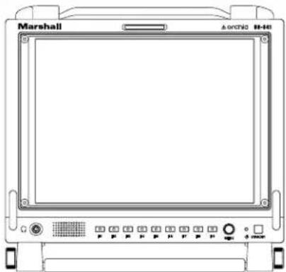
Front
natural_image
Front view of a Marshall medical monitor with control buttons and display screen (no readable text or symbols)Rear
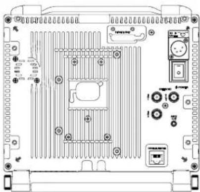
natural_image
Technical line drawing of an electronic device rear panel with ventilation slots and ports (no text or symbols)Dimensions
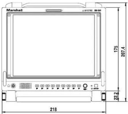
text_image
Marshall △0°25'80" 10-14" 175 207.4" 22.2" 218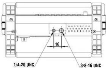
text_image
1/4-20 UNC 16 3/8-16 UNC■ PANEL
| Screen Size | 8.4” Diagonal |
| Display Area (h x v) | 6.7” x 5” |
| Aspect Ratio | 4:3 |
| Pixels | 1024 x 768 |
| Color Depth | 8-bit (16.7M colors) |
| Viewing Angle (h x v) | 85° + 85° (H) 50° + 60° (V) |
| Brightness | 400 cd/m ^2 |
| Contrast Ratio | 400:1 |
Video Input - 2 x BNC Female (75 Ω)
Video Output (Active Loop-Through) - 1 x BNC Female (75 Ω)
Parallel Remote - RJ-45
Optional Input Slot
Audio Output Jacks - 3.5mm Stereo x 2. One Front and One Rear.
Service Terminal
Power Input - 4-Pin Male XLR
Pin 1: GND
Pin 2: N/C
Pin 3: N/C
Pin 4: +12VDC
■ ELECTRICAL
Power Consumption - 1.5 Amp (Max) @ 12VDC (18W Max)
Voltage Requirement - 12VDC (10VDC-18VDC)
■ MECHANICAL
| Dimensions (w x h x d) | 8.6” x 8.2” x 1.7” |
| Weight (Monitor Only) | 4.6 lbs including power adapter |
| Operating Temperature | 32° F to 104° F (0° C to 40° C) |
| Storage Temperature | -4° F to104° F (-20° C to 40° C) |
| RoHs | Do not dispose. Return to Manufacturer or Authorized Recycle Facility. |
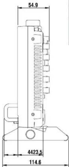
text_image
54.9 4423.5 114.6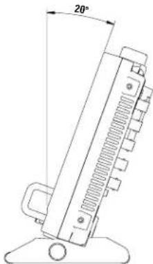
natural_image
Technical line drawing of a mechanical component with a 20-degree angle标注 (no text or symbols beyond the dimension)Maintenance / Color Calibration Procedure
■ Screen Cleaning
Periodically clean the screen surface using ammonia-free cleaning wipes (Marshall Part No. V-HWP-K). A clean micro-fiber cloth can also be used using only non-abrasive and ammonia-free cleaning agents. Do not use paper towels. Paper towel fibers are coarse and may scratch the surface of the polycarbonate faceplate or leave streaks on the surface. Antistatic and fingerprint resistant cleaning agents are recommended. Do not apply excessive pressure to the screen to avoid damaging the LCD.
■ Faceplate Dusting
Dust the unit with a soft, damp cloth or chamois. Dry or abrasive cloths may cause electrostatic charge on the surface, attracting dust particles. Neutralize static electricity effects by using the recommended cleaning and polishing practice.
■ Color Calibration Procedure
- Allow both the unit you want to calibrate and the Minolta® CA-210 to warm up for a minimum of 20 minutes.
- Attach the CA-210 color probe to the update dongle.
- With the unit still turned on, insert the update dongle into the service port at the rear of the OR-841-HDSDI.
- Use the RotoMenu navigation control and go to:
Color Menu
Color Temp
• Cal D65/D93 to calibrate both
• Cal D65 to calibrate only D65
- Cal D93 to calibrate only D93
Press enter once to select and again to confirm
- Follow the on-screen instructions
Notes:
- If there is no color probe attached or you make a mistake and try to calibrate the incorrect screen, you will get an error message and the screen will default to previous settings.
- If the calibration process is interrupted while in progress, the current screen settings will be corrupted and the calibration process will have to be repeated.
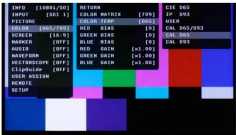
text_image
INFO [1080i/50] INPUT [SDI 1] PICTURE COLOR [065/709] SCREEN [16:9] MARKER [OFF] AUDIO [OFF] WAVEFORM [OFF] VECTORSCOPE [OFF] ClipGuide [OFF] USER ASSIGN REMOTE SETUP RETURN COLOR MATRIX [709] COLOR TEMP [065] RED BIAS [0] GREEN BIAS [0] BLUE BIAS [0] RED GAIN [x1.00] GREEN GAIN [x1.00] BLUE GAIN [x1.00] CIE D65 JP D93 USER CAL D65/D93 CAL D65 CAL D93Warranty
Marshall Electronics warranties to the first consumer that this OR-841-HDSDI LCD monitor will (under normal use) be free from defects in workmanship and materials, when received in its original container, for a period of one year from the purchase date. This warranty is extended to the first consumer only, and proof of purchase is necessary to honor the warranty. If there is no proof of purchase provided with a warranty claim, Marshall Electronics reserves the right not to honor the warranty set forth above. Therefore, labor and parts may be charged to the consumer. This warranty does not apply to the product exterior or cosmetics. Misuse, abnormal handling, alterations or modifications in design or construction void this warranty. It is considered normal for a minimal amount of pixels, not to exceed three, to fail on the periphery of the display active viewing area. Marshall Electronics reserves the option to refuse service for display pixel failure if deemed unobtrusive to effective use of the monitor by our technicians. No sales personnel of the seller or any other person is authorized to make any warranties other than those described above, or to extend the duration of any warranties on behalf of Marshall Electronics, beyond the time period described above. Due to constant effort to improve products and product features, specifications may change without notice.
Marshall Electronics, Inc.
1910 East Maple Avenue
www.LCDracks.com / sales@lcdracks.com