Orchid OR-70-3D - Watch MARSHALL - Free user manual and instructions
Find the device manual for free Orchid OR-70-3D MARSHALL in PDF.

User questions about Orchid OR-70-3D MARSHALL
0 question about this device. Answer the ones you know or ask your own.
Ask a new question about this device
Download the instructions for your Watch in PDF format for free! Find your manual Orchid OR-70-3D - MARSHALL and take your electronic device back in hand. On this page are published all the documents necessary for the use of your device. Orchid OR-70-3D by MARSHALL.
USER MANUAL Orchid OR-70-3D MARSHALL
Marshall Electronics
Marshall Electronics warranties to the first consumer that this OR-70-3D LCD monitor will (under normal use) be free from defects in workmanship and materials, when received in its original container, for a period of one year from the purchase date. This warranty is extended to the first consumer only, and proof of purchase is necessary to honor the warranty. If there is no proof of purchase provided with a warranty claim, Marshall Electronics reserves the right not to honor the warranty set forth above. Therefore, labor and parts may be required to apply to the product contractor's refuse or misuse, abnormal handling, alterations or modifications in device or construction void this warranty. It is considered normal for a
minimal amount of pixels, not to exceed three, to fail on the periphery of the display active viewing area.
orchid
OR-70-3D
Fully-Featured 7" ORCHID Auto-Stereoscopic 3D Camera-Top / Field Monitor
natural_image
Line drawing of a rectangular electronic device with control panel and indicator lights (no text or symbols)Owners Manual
Marshall Electronics, Inc.
1910 East Maple Avenue
www.LCDracks.com/sales@lcdracks.com
2011 10 07 v 0.06
Contents
- Product Overview 3
1.1 Overview 3
1.2 Features 4 - Specifications 6
2.1 Technical Specifications 6
2.2 Dimensions (mm) 8 - Installation....9
3.1 Installation and Initial Setup 9
3.2 Optional Accessories....9 - Operation 10
4.1 Front Panel Features 10
4.2 Rear Panel Features....11
4.3 OR-70-3D Menu Structure....12 - Maintenance 15
Warranty....16
5. Maintenance

Screen Cleaning
Periodically clean the screen surface using ammonia-free cleaning wipes (Marshall Part No. V-HWP-K).
A clean micro-fiber cloth can also be used using only non-abrasive and a cleaning agents. Do not use paper towels. Paper towel fibers are coarse and may scratch the surface of the polycarbonate faceplate or leave streaks on the surface. Antistatic and fingerprint resistant cleaning agents are recommended

Faceplate Dusting
Dust the unit with a soft, damp cloth or chamois. Dry or abrasive cloths may cause electrostatic charge on the surface, attracting dust particles. Neutralize static electricity effects by using the recommended cleaning and polishing practice.
4.3 OR-70-3D Menu Structure
| REMOTE | PIN 1-PIN 6PIN 5 GROUND | R TALLY |
| G TALLY | ||
| B TALLY | ||
| LEFT R TALLY | ||
| LEFT G TALLY | ||
| LEFT B TALLY | ||
| RIGHT R TALLY | ||
| RIGHT G TALLY | ||
| RIGHT B TALLY | ||
| MARKER | ||
| 3D | ||
| 3D TPR (G+R) | ||
| ANAGLYPH | ||
| BLENDING | ||
| CHECK BOX | ||
| COMPARE BOX | ||
| H MARKER | ||
| LEFT EYE | ||
| RIGHT EYE | ||
| S-D-S (SIDE BY SIDE) | ||
| SDI ERROR | ||
| Y DIFF | ||
| Y DIFF MONO | ||
| ZEBPA | ||
| SDI STATUS | RETURN | |
| ERROR COUNT 0-9999 | ||
| RESET COUNTER | ||
| DISPLAY OFF / ON / AUTO | ||
| SETUP | RETURN | |
| TIMECODE | OFF / ON | |
| LTC | ||
| VITC 1 | ||
| VITC 2 | ||
| BACKLIGHT 1 TO 100%PICTURE DELAY NORMAL / FAST / FASTEST | ||
| FAN CONTROL AUTO, MAX. OFF | ||
| RESET TO MFG DEFAULT > RESET NOW / CANCEL | ||
1. Product Overview
1.1 Overview
Marshall's OR-70-3D is the world's first portable 7-inch 3D production monitor with innovative "glasses free" auto-stereoscopic technology. This lightweight 3D monitor does not require passive or active glasses and can be used as a camera viewfinder or portable 3D production display. With parallax barrier and lenticular hybrid technology, the OR-70-3D provides superior 3D images with 1600 x 600 screen resolution. For precision 3D calibration, the OR-70-3D provides dual waveform and vectorscope, along with various 3D analysis features such as checkbox, difference, blending, compare, and more. Integrated mux and independent loop-through eliminate the requirement of an additional external converter. Delay compensated horizontal mirror flip supports both channels respectively. Like most portable Marshall monitors, this unit also supports large battery adapters.
1.2 Features
High Resolution 7.2" Panel
The OR-70-3D features an all-digital TFT-MegaPixel active matrix LCD system. The LCD panel features a nominal brightness of 320 cd/m ^2 and a contrast ratio of 600:1 making each display ideal in a variety of environments and lighting conditions.
Compare Box
This New Innovative feature for 3D calibration compares a specific region of both channels using easily readable bar-graphs for Y,R,G,B with numeric display. Compare Box is now must-have feature for precision 3D camera alignment.
Check Box (a.k.a checkerboard)
Checkbox provides quilted layout of both left and right channels for depth check, channel difference, and etc. The size of box can be easily adjusted by using the "Peaking" rotary encoder.
Emboss (Alpha-Channel View)
Full Frame Embossed or Luminance Difference View shows the difference between Left Eye and Right Eye.
Y Diff
Enhanced Y diff provides for better recognition of depth
H Marker
New horizontal marker provided as a ruler for 3D depth control. The position and space between lines are adjustable using the "Bright" and "Contrast" rotary encoders.
Waveform monitor function
The built-in waveform monitor (which includes adjustable White and Black clip level indicators) can be displayed in various aspect ratios, positions, and transparency options. The Waveform Monitor not only monitors luminance, but can also warn the user of out-of-range conditions such as overexposure or "blacker-than-black" errors with fully user-adjustable warning limits.
Real-time Color Vectorscope
The built-in Vectorscope allows users to monitor color gamut range in real time. It displays in full color and can also be displayed in various layouts. The Vectorscope has adjustable gain from 1x to 5x.
ClipGuide
The ClipGuide function operates with both the Waveform display and Monochrome/Color picture display. Both the upper and lower ClipGuide levels are user-adjustable in order to accurately display over-and-under exposures during different shooting conditions. For example, the upper ClipGuide limit may be set to 85 IRE and the lower limit to 10 IRE. With these settings, any exposures over the set limit of 85 IRE will display red on both the Waveform and picture (if selected). The same will be true for blacks under 10 IRE.
4.3 OR-70-3D Menu Structure
| ANALYSIS | RETURN | |
| WAVEFORM OFF LEFT EYE,RIGHT EYE, BOTH | ||
| Y OVER LIMIT | 7.3 TO 106.1% [103.2%] | |
| Y UNDER LIMIT | 7.3% TO 100.1% [1.9%] | |
| VECTORS CODE | OFF,LEFT EYE,RIGHT EYE,BOTH | |
| GAIN | X:00 to X4.91 | |
| COMPARE BOX OFF ON | ||
| HORIZONTAL MOVE | USE ROTARY | |
| VERTICAL MOVE | USE ROTARY | |
| ZEBRA | RETURN | |
| ZEBRA | OFF ON | |
| MODE | YON MONO | |
| C | ||
| C ON MONOT & C ON MONO | ||
| DISPLAY TYPE ZEBRA / FILL | ||
| Y UPPER LIMIT | 7.3 TO 106.1% [103.2%] | |
| Y LOWER LIMIT | 7.3% TO 100.1% [1.9%] | |
| C UPPER LIMIT | TO 256 [240] | |
| C LOWER LIMIT | TO 256 [16] | |
| DISPLAY TYPE ZEBRA / FILL | ||
| Y UPPER LIMIT [100.0%] % IRE | 7.3% TO 109.1% | |
| Y UNDER LIMIT [0.0%] % IRE | 7.3% TO 108.1% | |
| C UPPER LIMIT | 3-255 [016.7.5 IRE,235.100 IRE] | |
| C LOWER LIMIT | 3-255 [016.7.5 IRE,235.100 IRE] | |
| USER ASSIGN | RETURN | |
| F-1 THRU-F-6REMOTE 1-3 | INPUT SELECT | |
| 3D REVIEW | ||
| VIEW MODE | ||
| LAYOUTS | ||
| COLOR CHANNEL | ||
| MARKER | ||
| 3D | ||
| 3D TPO [G.I.R] | ||
| ANAGLIPH | ||
| BLENDING | ||
| CHECK BOX | ||
| COMPARE BOX | ||
| H MARKER | ||
| LEFT EYE | ||
| RIGHT EYE | ||
| 5-3-S (SIDE BY SIDE) | ||
| SD/ERROR | ||
| Y DIFF | ||
| Y DIFF MONO | ||
| ZEBRA | ||
| FAN STOP | ||
| REMOTE L IR | BLENDING | |
| CHECK BOX | ||
| Y DIFF | ||
| Y DIFF MONO | ||
| ANAGLIPH | ||
| 3D | ||
| S & S (SIDE BY SIDE) | ||
4.3 OR-70-3D Menu Structure
| INFO | INPUT DUAL | |
| VIDEO FORMAT 1080 / 60 | ||
| MODEL NAME OR 70-3D | ||
| VERSION 1,2 | ||
| INPUT | RETURN | |
| SINGLE LEFT LINK | ||
| SINGLE RIGHT LINK | ||
| DXIAL LINK | ||
| FLIP VIEW LEFT OFF/ON | ||
| FLIP VIEW RIGHT OFF/ON | ||
| PICTURE | RETURN | |
| CHROMA 0-100 [50] is Calibetas acting | ||
| PEAKING | WHITE | |
| RED | ||
| GREEN | ||
| BLUE | ||
| SCREEN | RETURN | |
| VIEW MODE | LEFT EYE | |
| RIGHT EYE | ||
| S & S (SIDE BY SIDE) | ||
| 3D | ||
| 3D REVIEW | RETURN | |
| OFF | NORMAL, OVERSCAN, ZOOM | |
| BLENDING | ||
| Y DIFF | ||
| Y DIFF MOND | ||
| CHECK BOX SIZE | 0 - 63 [10] | |
| ANAGLYPTI | OFF | |
| COLOR | ||
| HALF COLOR | ||
| OPTIMIZED | ||
| GRAY | ||
| MARKER | RETURN | |
| MARKER | ON/OFF | |
| CENTER | ON/OFF | |
| ASPECT RATIO | OFF | |
| 4:3 | ||
| 16:3 | ||
| 1.85:1 | ||
| 2.35:1 | ||
| 4:3 & 1.85 | ||
| 4:3 & 2.35 | ||
| 16:3 7:4:3 | ||
| SAFETY ZONE | 80% TO 100% [OFF] [95%] | |
| MARKER MAT | CLEAR, HALFTONE, BLACK | |
| LINE THICKNESS | 1, 2, 3 | |
| LINE TYPE | GRAY, HALFTONE, WHITE INVERT | |
| CROSS HATCH | OFF | |
| SMALL | ||
| MEDIUM | ||
| LARGE | ||
| H MARKER | ON/OFF | |
| INTERVAL | 0.35% TO 8.00% [4.00%] | |
| OFFSET | 0 TO 22 [0] |
Chroma monitor function
Included in the ClipGuide menu are settings for monitoring color gamut errors, which can occur in color space conversion. Any data exceeding these values will be displayed as Yellow in the picture. The factory preset for Climits are 16 and 240 according to ITU-R BT.709. Typically, these values should not be exceeded during normal video production.
Precision White Balance with Color Temperature Adjustment
White balance adjustment is essential in order to render colors correctly. To display colors correctly, gray scale should maintain identical color temperature. The white balance for ORCHID monitors defaults to D65 (6500K) so the user does not need to adjust white balance. LCD monitors have color-matching issues because white balance can be affected by a change in luminance level. Our unique color management system solves this problem. The ORCHID operating system includes an Automatic White Balance function that allows a "One Button" calibration procedure when used with a Minolta CA-210 color probe. All Orchid Series LCD panels are calibrated at the factory to ensure color conformity between screens.
Select color temperature and gamma mode
Color temperature presets may be selected between D65 or D93 as well as user-defined settings. Gamma settings are adjustable from 1.0 to 3.0 in 0.1 steps. The standard setting is 2.2.
Flexible Screen Markers
A variety of screen markers in 4:3, 16:9, and full screen modes allow accurate monitoring of the different aspect ratios used in broadcast environments.
User-Definable Function Buttons
Six user-definable function buttons and one Rotary Encoder on the front panel allow quick access to numerous
settings and features including Input 1, Input 2, Option Input, Wavelength, Vectorscope, Audio Bars, aspect ratio, screen markers, monochrome mode, H/V delay mode, and more.
2. Specifications
2.1 Technical Specifications
| OR-70-3D | ||||
| Panel | Type | TFT LCD, 3D View | ||
| Display Area(mm) | 146.4x109.8, 7.2"(Diagonal Wide) | |||
| Pixels | 1600(H)x600(V), HDDP(Horizontally Double Density Pixel) | |||
| Pixel Pitch(mm) | 0.183(H)x0, 183(V) | |||
| Color Depth | 16.7M, 24bit true color | |||
| Brightness (cdm2) | 320 | |||
| Contrast Ratio | 600:1 | |||
| INPUT SCI | SMPTE-424M | 3G(2.970Gb/s) | 2xBNC | |
| SMPTE-202 | HD(1.485Gb/s) | |||
| SMPTE-259M | SD(270Mbps) | |||
| OUTPUT SDI | SMPTE-424M | 3G(2.970Gb/s) | 2xBNC(Left/Right Loop through)2xBNC(Side by Side Half) | |
| SMPTE-202 | HD(1.485Gb/s) | |||
| SMPTE-259M | SD(270Mbps) | |||
| Compatible Formats | SDI Dual Stream | SMPTE 425 A | YCsCp, 4:2:2, 10bit | 1080p(60/59.94/50) |
| YCsCp, 4:2:2, 12bit | 1080p(30/29.97/25/24/23.98)1080p(60/59.94/50)1080PsF(30/29.97/25/24/23.98)1080p(60/59.94/50)1080PsF(30/29.97/25/24/23.98)720p(60/58.84/50:30/29.97/25/24/23.98) | |||
| YCaCr(RGB)4:4:1, 10bit | ||||
| YGcCr(RGB)4:4:12bit | 1080p(30/29.97/25/24/23.98)1080p(60/59.94/50)1080PsF(30/29.97/25/24/23.98)720p(60/58.84/50:30/29.97/25/24.23.98) | |||
| YCsCpA(RGBA)4:4:4:4 10bit | ||||
| 2xSMPTE 274M | YCsCp, 4:2:2, 10bit | 1080p(60/59.94/50)1080p(30/29.97/25/24/23.98)1080PsF(30/29.97/25/24/23.98)720p(60/58.84/50:30/29.97/25/24/23.98) | ||
| 2xSMPTE 296M | YCsCp, 4:2:2, 10bit | 720p(60/58.84/50:30/29.97/25/24/23.98) | ||
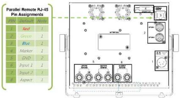
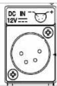
4.2 Rear Panel Features
text_image
Parallel Remote RJ-45 Pin Assignments PIN Default Note 1 Red 1 2 Green 1 3 Blue 1 4 Marker 1 5 GND 2 6 Input 1 1 7 Input 1 1 8 Aspect 1① 4-Pin XLR male Power Connector.
② Option Connectors for Tally and Remote
③ Parallel Remote Connector (RJ-45 User Assignable Functions)
④ Service Port
(for use with optional OR-SM service module to upgrade firmware and perform color calibration
⑤ 3G/SD/HD-SDI Inputs (BNC)
⑥ Re-clocked 3G/SD/HD-SDI Output (BNC)
4. Operation
4.1 Front Panel Features
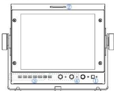
text_image
Technical diagram of a device front panel with labeled components and control buttons① Power Button with Indicator
Press power switch to turn on the Unit. The Indicator LED will turn Green. Press again to put the OR-70-3D into standby mode. The LED will turn Red.
② Tri-Color Tally Light
30mm Tri-Color tally lamp controlled via the Remote connector on the rear of the unit.
③ User-Definable Function Keys
Six user-definable function buttons can be used for direct access to various settings. Functions are assigned using the on-screen menu.
④ Rotary Encoders
In normal operation the Rotary Encoders control Brightness / Contrast / and Peaking. Turning the encoder will allow the user to make adjustments to the indicated mode. These same rotary encoders also function as adjustment controls for the Check Box, Compare Box and H-Marker Analysis functions as well as Menu navigation.
ROTOMENU Control
Press the Menu Key to access the on-screen Menu. Turn the "Bright" encoder to the Left or Right to navigate Up and Down on the on-screen menu. Press the encoder to select the submenu. When you arrive at the sub-menu or value you wish to modify, turn the encoder to select the new value and then press the Encoder to save the change. If you exit the data entry submenu before pressing the Encoder, the changes will not be saved. You may exit submenus by turning the Encoder to the Return heading and pressing the Encoder to select, or simply by pressing the Menu key.
| SDI Single Stream(Sido by SideHalf) | SMPTE 425AB | YC_eC_s , 4:2.2, 10bit | 1080x(60/59.94/50) | |
| YC_uC_t , 4:2.2, 12bit | 1080x(30/29.97/25/24/23.98)1080(50/59.94/50)1080PsF(30/29.97/25/24/23.98) | |||
| YC_eC_s(RGB) 4:4.4, 10bit | 1080x(30/29.97/25/24/23.98)1080(50/59.94/50)1080PsF(30/29.97/25/24/23.98)720p(50/59.94/50/30/29.97/25/24/23.98) | |||
| YC_eC_s(RGB) :4:4.4,12bit | 1080x(30/29.97/25/24/23.98)1080(50/59.94/50)1080PsF(30/29.97/25/24/23.98)720p(50/59.94/50/30/29.97 /25/24/23.98) | |||
| YC_eC_sN(RGBA) :4:4.4, 10bit | 1080x(30/29.97/25/24/23.98)1080(50/59.94/50)1080PsF(30/29.97/25/24/23.98)720p(50/59.94/50:30/29.97/25/24/23.98) | |||
| SMPTE274M | YC_eC_s , 4:2.2, 10bit | 1080(50/59.94/50)1080p(30/29.97/25/24/23.98)1080PsF(30/29.97/25/24/23.98) | ||
| SMPTE296M | YC_eC_s , 4:2.2, 10bit | 720p(50/59.94/50/30/29.97/25/24/23.98) | ||
| General | Power Supply | 6~18 VDC | ||
| PowerConsumption | 24W (12V, 2A) | |||
| REMOTE | PARALLEL | 7 GPI(General Purpose Input) | ||
| OPTION-1 | Remote Control Module Interface | |||
| OPTION-2 | EXTERNAL TALLY INTERFACE | |||
| Operation | Temperature | 0°C~40°C | ||
| Humidity | 30%~85% | |||
| Storage | Temperature | 10°C~40°C | ||
| Humidity | 0%~90% | |||
| Weight(Kg) | 1.3Kg | |||
| Dimensions(WxDxH, mm) | 188x42x161 | |||
2.2 Dimensions (mm)
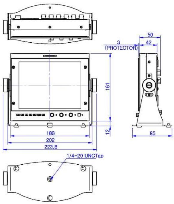
text_image
3 (PROTECTOR) 161 12 188 202 223,8 95 50 42 1/4-20 UNCTap3. Installation
3.1 Installation and Initial Setup
Carefully unpack the OR-70-3D and verify that the following items are present
- OR-70-3D with battery adapter
• 12 volt AC/DC Power adaptor
4-pin XLR connector14.4V (Anton Bauer-Mount).
. PIN 1: GND 7.2V (Small battery mount).
. PIN 2: N.C. Operating voltage 7\~30VDC
- PIN 4: +12VDC
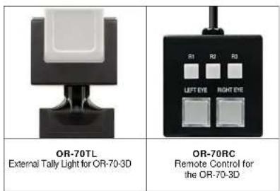
3.2 Optional Accessories