QVW-1708 - Suivi MARSHALL - Free user manual and instructions
Find the device manual for free QVW-1708 MARSHALL in PDF.

User questions about QVW-1708 MARSHALL
0 question about this device. Answer the ones you know or ask your own.
Ask a new question about this device
Download the instructions for your Suivi in PDF format for free! Find your manual QVW-1708 - MARSHALL and take your electronic device back in hand. On this page are published all the documents necessary for the use of your device. QVW-1708 by MARSHALL.
USER MANUAL QVW-1708 MARSHALL
Marshall Electronics
Model No. QVW-1708
17.3" Quad-Viewer Monitor with 4K Format Support
natural_image
Technical line drawing of a rectangular electronic device with mounting flanges and internal components (no text or symbols)Operating Instructions
Table of Contents
Installation and Accessories....3
Monitor Front....4
Monitor Rear 4
Front Controls .... 5
Rear Inputs 6
Compatible Input Formats....7
Screen Layouts 8
On Screen Menu....10
Marker Setup Submenu 11
Video Configuration Submenu 12
Color Configuration Submenu....15
System Configuration Submenu 16
OSD Configuration Submenu....18
Audio Config Submenu 21
IMD Config Submenu....22
IMD Fixed Config Submenu 24
IP Config Submenu....25
Service Submenu....26
Monitor Specifications....27
Dimensions 28
Warranty 32
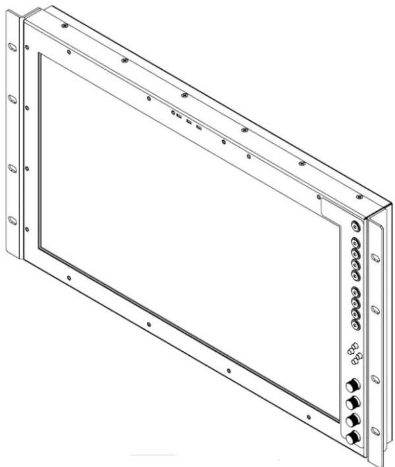
Installation and Accessories
Unpacking
Carefully unpack the QVW-1708 monitor and verify that the following items are included:
- QVW-1708 Monitor
- V-PS12V-5A-XLR Power Supply
- Operating Instructions
Accessories
The QVW-1708 supports VESA standard 75 mm hole pattern accessories. Additionally, a desktop stand is available for this product. Please contact Marshall Electronics for further information.
Monitor Front
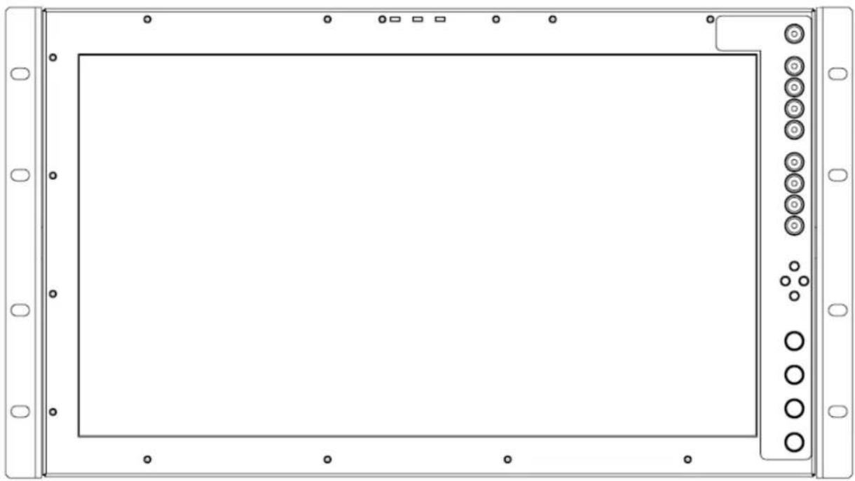
natural_image
Front view of a rectangular electronic device with mounting flanges and circular components on the right side (no text or symbols)Monitor Rear
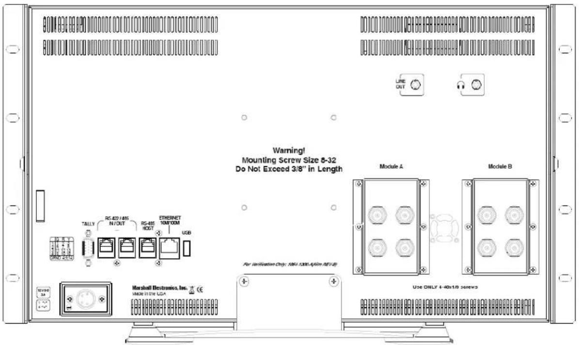
text_image
Warning! Mounting Screw Size 8-32 Do Not Exceed 3/8" in Length TALLY RS.422/48S IN/OUT RS-48S HOLT ETRESNET 10M/100M USB For Verification Only: N61.130A/48s SEY-8 Marshall Electronics, Inc. USE ONLY 4-40s10 screws Module A Module BFront Controls
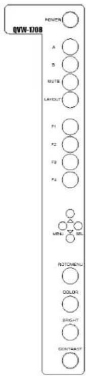
text_image
QVW-1708 POWER A B MUTE LAYOUT P1 P2 P3 P4 MENU ROTOMENU COLOR SIGHT CONTRASTPOWER
Control Power going to the front panel.
A - B (Input buttons)
Press the A or B to select which module input to display on the screen. Each press of an input button cycles between the available inputs on that module.
MUTE
Press the MUTE button to mute the output to the headphone jack.
Layout
Press the LAYOUT button to cycle between the available screen layouts.
F1 - F4 (Function buttons)
Press the F1, F2, F3 or F4 buttons to activate the selected functions. The function activated can be changed on the on screen menu.
MENU / ↑ / ↓ / SEL
As an alternative to the ROTOMENU™, these buttons provide the ability to navigate through the menu with the MENU / ↑ / ↓ / SEL buttons.
ROTOMENU™
The RotoMenu™ knob is an alternate means of accessing and navigating the main menu, using only a single control. See the Using the RotoMenu knob section for details on using the RotoMenu. Also, turning the RotoMenu™ knob before pressing it adjusts the Headphone volume on monitors with an available Headphone Jack.
COLOR, BRIGHT, CONTRAST (Image Adjustment Knobs)
Use the image adjustment knobs to adjust color saturation, brightness and contrast of the image. The status of each image adjustment parameter is shown on the bottom left of the screen, with values ranging from 0 to 100. Pressing a knob once displays the current value. Pressing a knob twice resets the corresponding adjustment to the default setting.
Rear Inputs
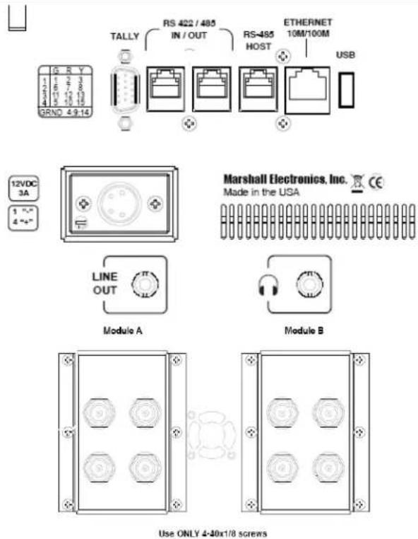
text_image
TALLY RS 422 / 485 IN / OUT RS-485 HOST ETHERNET 10M/100M USB GRND 4.9-14 12VDC 3A 1 "- 4 "- LINE OUT Module A Module B Use ONLY 4-40x1/8 screwsLINE OUT
The Line Out, 1/8", jack on the back of the monitor takes two channels of embedded SDI audio and provides a Line Level Output. The volume is constant and can not be adjusted via the VOLUME or MUTE functions on the monitor.
Headphone Jack
The Headphone, 1/8", jack on the front panel takes two channels of embedded SDI audio for your listening pleasure. The Headphone jack provides audio with adjustable levels via the ROTOMENU knob.
TALLY
OSD tally and GPI can be activated via the HD-15 connector by connecting the corresponding pin to ground via dry contact.
A variety of external devices can be used to perform the contact closure. No additional power should be supplied to the HD-15 port.
RS-422 / 485 IN / OUT
The RS-422/485 ports are used to remotely control the MEI Protocol features. (Note: Connector/pin-out may need to be adapted depending on protocol and controlling device used). Only one connection to either port is needed to control the monitor. The second port
can be used to loop multiple monitors in the same bus. See IMD CONFIGURATION SUBMENU for further details.
RS-485 HOST
Use the RS-485 HOST port to receive data input from Image Video or TSL protocols.
ETHERNET 10M / 100M
You can use the Ethernet port to access the MEI Remote Control page via a web browser such as IE or Firefox. Network connectivity can be setup in the IP Config menu.
USB (Input port)
The USB port is used for field upgrades. Contact Marshall Electronics for further information.
Module A - Module B
Input slots can be pre-configured at the factory with a variety of modules. Contact Marshall Electronics for information on options.
Power Input
Connect the power input connector here. Power can be supplied from the included power supply, or from a variety of DC sources supplying the voltage and current listed on the silkscreen.
Compatible Input Formats
SDI / HDSDI Formats
567i 50, 625i 59.94
720p 23.98, 24, 25, 29.97, 30, 50, 59.94, 60
1035i 59.94, 60
1080p 23.98, 23.98sF, 24, 24sF, 25, 29, 30
1080i 50, 59.94, 60
3G SDI Formats
Level A 1920 x 1080 p
50, 59.94, 60p
23.98, 23.98sF, 24, 24sF, 25, 25sF, 29.97, 29.97sF, 30, 30sF
Level A 1920 x 1080 i
50, 59.94, 60i
Level A 1280 x 720 p
50, 59.94, 60
23.98, 24, 25, 29.97, 30
Level A 2k x 1080 p
23.98, 23.98sF, 24, 24sF, 25, 25sF, 29.97, 29.97sF, 30, 30sF
Level B 1920 x 1080 p
50, 59.94, 60p
23.98, 23.98sF, 24, 24sF, 25, 25sF, 29.97, 29.97sF, 30, 30sF
Level B 1920 x 1080 i
50, 59.94, 60
Level B 2k x 1080 p
23.98, 23.98sF, 24, 24sF, 25, 25sF, 29.97, 29.97sF, 30, 30sF
4K Formats
4096 x 2160 p
4K 50,59.94, 60
4K 23.98
3840 x 2160 p
4k 50, 59.94, 60
4k 23.98
Input formats that exceed the native display resolution (such as 4K inputs) will be scaled to fit. Best scaling performance occurs with Progressive "p" inputs vs. segmented-frame "sF" inputs.
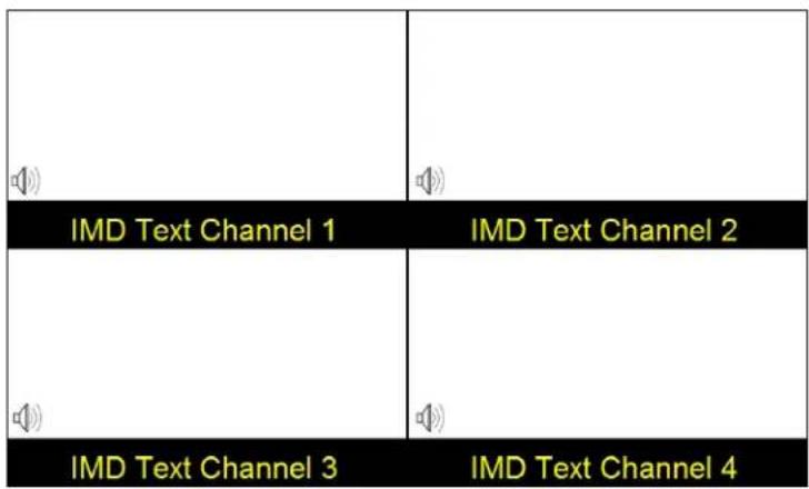
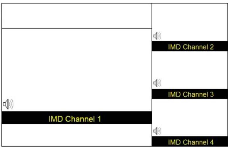
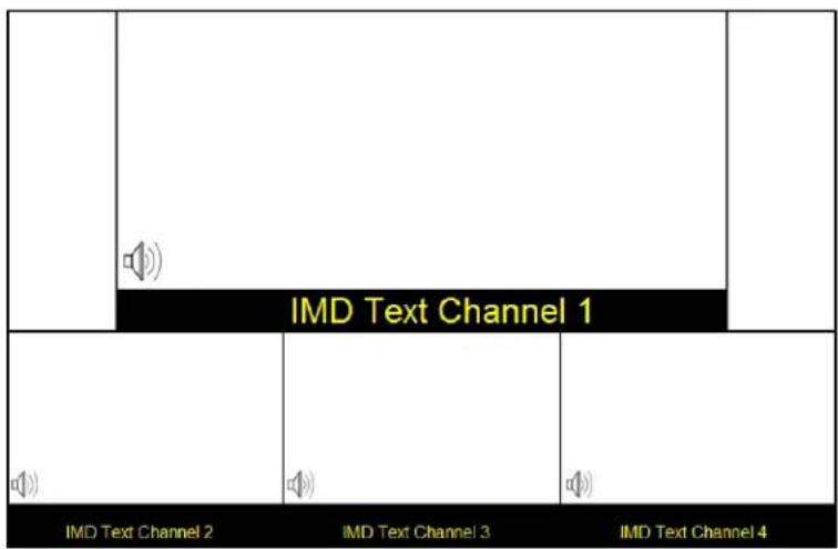
Screen Layouts
The QVW-1708-Q can display 4 different input sources simultaneously. Each source is scaled and positioned to fit the desired layout. There are a total of 4 different layouts illustrated below. Each press of the Layout Button will switch to the next available layout.
text_image
IMD Text Channel 1 IMD Text Channel 2 IMD Text Channel 3 IMD Text Channel 4Default Quad Layout
text_image
IMD Channel 1 IMD Channel 2 IMD Channel 3 IMD Channel 4Quad Layout 2
text_image
IMD Text Channel 1 IMD Text Channel 2 IMD Text Channel 3 IMD Text Channel 4Quad Layout 3
| IMD Channel 1 | IMD Channel 2 |
Layout 4
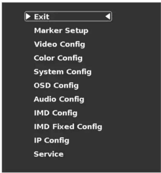
On Screen Menu
Access and navigate the main menu using the RotoMenu™ knob:
text_image
Exit Marker Setup Video Config Color Config System Config OSD Config Audio Config IMD Config IMD Fixed Config IP Config ServiceMain Menu
Using the RotoMenu knob
- Press the RotoMenu™ knob to enter the main menu.
- Rotate the knob to scroll up or down in the main menu or each submenu.
- Press the RotoMenu™ knob to enter a submenu or choose a setting.
• To return to main menu from submenu, select 'Back' and press the RotoMenu™.
The menu timeout can be set in the OSD Timeout section of the OSD Config submenu.
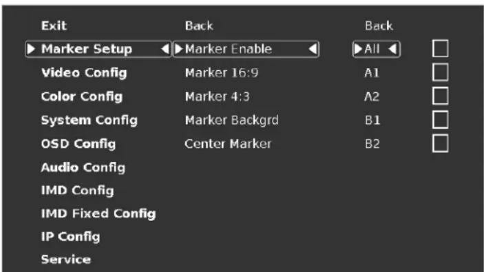
Making Changes to an Individual Channel
The Quad-Viewer RotoMenu allows for Video, Color, System, OSD and IMD Configuration changes to be made to individual channels in the Quad-Viewer system. Items in the menu that can be changed for each individual channel will have a A1, A2, B1, B2 indicator on the right side of the menu and a small white box for each individual channel, as shown below:
text_image
Exit Back Back ► Marker Setup ► Marker Enable ► All □ Video Config Marker 16:9 A1 □ Color Config Marker 4:3 A2 □ System Config Marker Backgrd B1 □ OSD Config Center Marker B2 □ Audio Config IMD Config IMD Fixed Config IP Config ServiceTo modify a channel, enter a specific submenu (Marker Setup) and a specific function in that submenu (Marker Enable) by highlighting it with the RotoMenu and pressing the knob to confirm your selection.
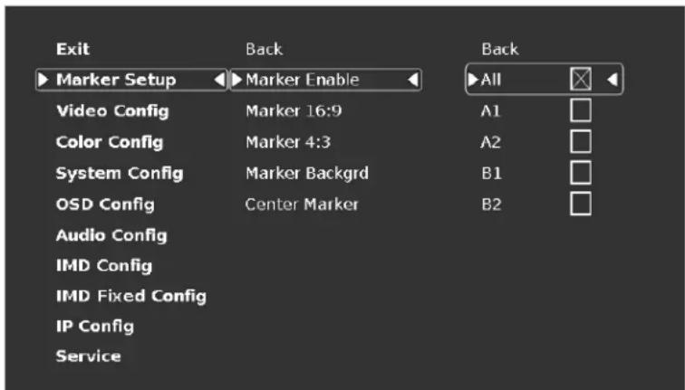
Your current position in the menu is indicated by the white highlighted box. When you have selected the desired function, you are given the option of modifying one channel or All channels. Using the RotoMenu, you can select which channel you would like to modify.
text_image
Exit Marker Setup Marker Enable Video Config Marker 16:9 Color Config Marker 4:3 System Config Marker Backgrd OSD Config Center Marker Audio Config IMD Config IMD Fixed Config IP Config Service Back AllWhen you apply a change to the particular channel (or All channels), a white X will appear in your chosen channel box when the setting is active in the channel, and the white X will go away when the setting is inactive.
When modifying the A1 channel, the All option will simultaneously be highlighted. This is normal operation and is used by the system software internally to keep track of channel selection and modification.
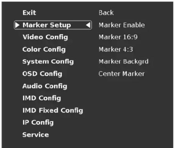
Marker Setup Submenu
Use the Marker Setup submenu to select various on screen marker options and the opacity of the area surrounding the markers.
text_image
Exit ► Marker Setup Video Config Color Config System Config OSD Config Audio Config IMD Config IMD Fixed Config IP Config Service Back Marker Enable Marker 16:9 Marker 4:3 Marker Backgrd Center MarkerMarker Setup Submenu
Marker Enable
Enable or disable on screen markers for each individual channel.
Marker 16:9, Marker 4:3
The Marker 16:9 and Marker 4:3 functions allow you to adjust the screen markers for the 16:9 and 4:3 Aspect Ratios, respectively.
Marker Backgrd
Use this function to set the opacity of the area outside of the on screen markers. You can choose between Off, 50% and Black.
Center Marker
Enable or disable the Center Marker cross hairs for each individual channel.
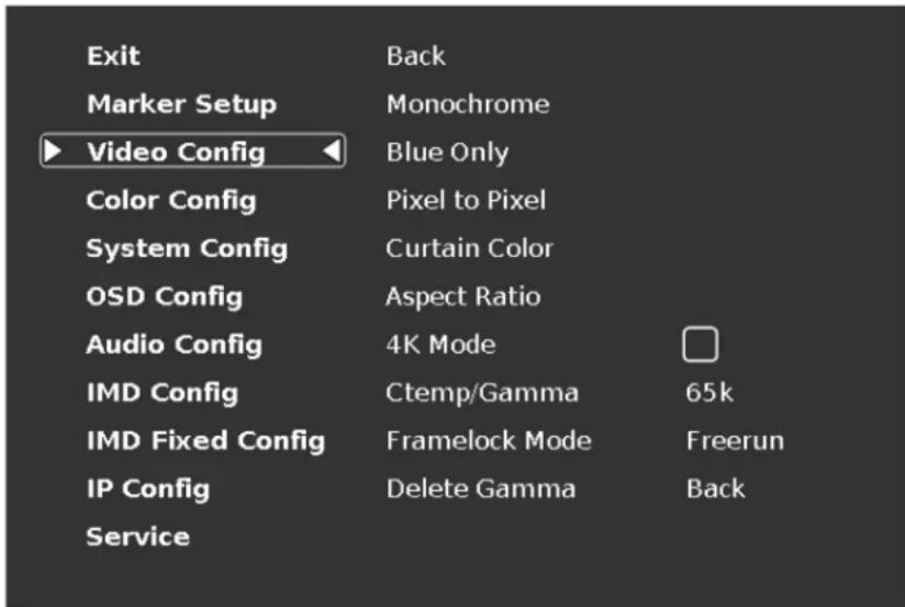
Video Configuration Submenu
Use the Video Configuration submenu to select various video settings such as 4K Mode, Pixel to Pixel mode and other picture related functions.
text_image
Exit Marker Setup Video Config Monochrome Blue Only Color Config Pixel to Pixel System Config Curtain Color OSD Config Aspect Ratio Audio Config 4K Mode IMD Config Ctemp/Gamma 65k IMD Fixed Config Framelock Mode Freerun IP Config Delete Gamma Back ServiceVideo Configuration Submenu
Monochrome Mode
Use this setting to enable monochrome mode. Only the luminance of the image will be displayed as a grayscale picture.
Blue-Only Mode
Use this setting to enable Blue-Only mode. This mode displays only the blue color component of the image, switching off the red and green components. Use this mode when calibrating the monitor to SMPTE color bars with the following procedure:
- Allow the monitor to warm up for at least 5-10 minutes.
- Display SMPTE split-field color bars on the monitor using an external source.
-
Enable Monochrome mode.
-
Locate the pluge pattern (super black, black, and gray bars) at the lower-right corner of the screen. Adjust the Brightness knob until there is no visible difference between the super black and black bars, but the gray bar is still visible.
-
Adjust the Contrast knob until an even grayscale appears along the top bars.
-
Disable Monochrome mode.
Enable Blue-Only mode and adjust the Color knob so that the outermost bars (white and blue) appear to match in brightness.
■ Pixel-to-Pixel Mode
Use this setting to enable Pixel-to-Pixel mode.
This mode bypasses the monitor's internal scaling function and displays images in their native resolution and aspect ratio, with a one-to-one mapping of incoming image pixels to screen pixels:
- For incoming formats smaller than the native resolution of the window (or selected aspect ratio), the image will be displayed in the center of the window using only the necessary LCD pixels. For example, 480i images will only occupy exactly 640x480 pixels in a particular channel window in Quad mode, or if the channel is selected full screen, it will occupy exactly 640x480 pixels in the center of the screen. The surrounding screen area will be black.
■ Curtain Color
Use this setting to choose the default color displayed on the screen when no video input is present. Available colors are red, green, white, black and blue.
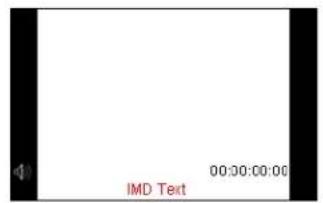
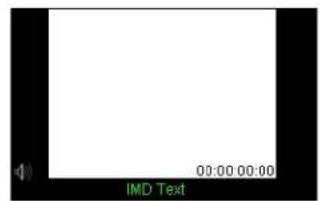
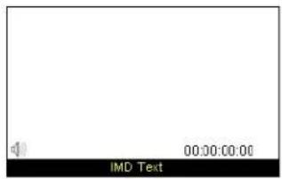
■ Aspect Ratio Settings
Use this menu option to switch between several aspect ratio settings.
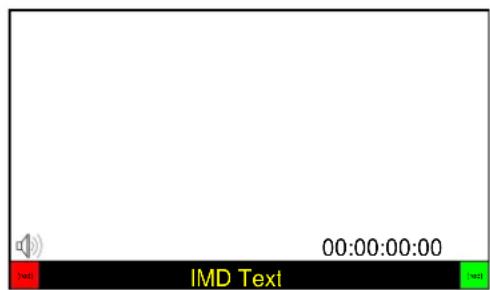
- In 4:3 mode, images are scaled up or down to fill the maximum 4:3 portion of the screen. IMD text and time code are superimposed on the lower portion of the image. The audio presence indicator and on-screen tally are displayed at the bottom of the screen, outside the image.
- In Scaled 4:3 mode, images are scaled to a smaller 4:3 portion of the screen, leaving space for IMD text, tally, and audio presence indicator to be displayed below or around the image. Time code is superimposed on the lower portion of the image.
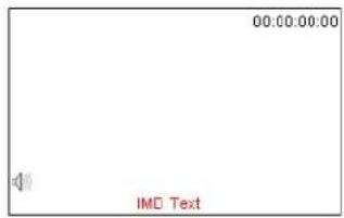
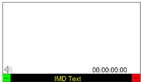
• In 16:9 mode, images are scaled to fill the maximum 16:9 portion at the top of the screen. In this mode, IMD text and on-screen tally are displayed below the image. Time code and the audio presence indicator are superimposed on the lower portion of the image.
• In Full Screen mode, images are scaled to fill the entire screen. In this mode, all OSD features are superimposed on the image.
The diagrams on the following page show how IMD text, timecode, and the audio monitor icon are simultaneously displayed on the screen in each aspect ratio setting. The white area represents the video image.
text_image
00:00:00:00 IMD Text4:3
text_image
00:00 00:00 IMD TextScaled 4:3
text_image
00:00:00:00 IMD Text16:9
text_image
00:00:00:00 IMD TextFull Screen (16:10)
4K Mode
Use this setting to enable the 4K Mode, which synchronizes all four inputs to allow the monitor to display a 4K signal. When in 4K mode, all functions in the menu will be available, and controls for COLOR, BRIGHTNESS and CONTRAST will work on all four quadrants simultaneously.
Ctemp/Gamma
Use this setting to choose one of three color temperature / gamma presets or to remove gamma settings:
• Linear (No gamma applied)
• 55K
• 65K
• 93K
- Custom Gamma 1-4
If a custom Gamma table has been loaded, it will appear in this section of the menu. Up to 4 Gamma tables can be stored CalMAN 5.2.0.1355 software or above
Delete Gamma
Use this function to delete gamma tables that have been stored on the monitor via CalMan 5.2.0.1355 software, or other compatible software.
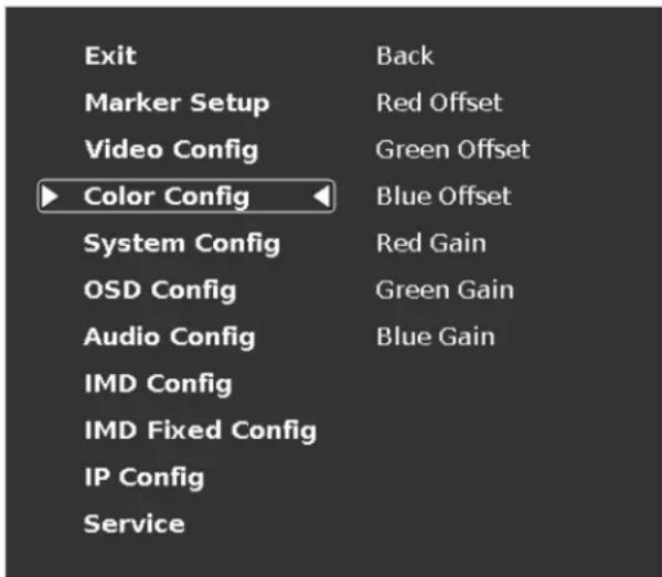
Color Configuration Submenu
Use the Color Configuration submenu to adjust the Red, Green and Blue Offset and Gain values of all four input channels.
text_image
Exit Marker Setup Video Config Color Config System Config OSD Config Audio Config IMD Config IMD Fixed Config IP Config Service Back Red Offset Green Offset Blue Offset Red Gain Green Gain Blue Gain■ Red, Green, and Blue Offset
Use the offset controls for red, green, and blue to adjust the color temperature of the display. Each setting adjusts the offset, or brightness, of each individual color component. These settings will affect whichever color temperature preset is selected.
■ Red, Green, and Blue Gain
Use the gain controls for red, green, and blue to adjust the color temperature of the display. Each setting adjusts the gain, or contrast, of each individual color component. These settings will affect whichever color temperature preset is selected.
Use the System Configuration submenu to control various system parameters such as GPI, function button settings and User definable presets.
text_image
Exit Back Marker Setup Green GPI Video Config Red GPI Color Config Yellow GPI ►System Config◀ Function 1 Marker OSD Config Function 2 Aspect Ratio Audio Config Function 3 Anc. Monitor IMD Config Function 4 Monochrome IMD Fixed Config Load Config Back IP Config Save Config Back ServiceSystem Configuration Submenu
■ Green, Red and Yellow GPI
Use the Green, Red and Yellow GPI menu items to set a certain action when the Green, Red or Yellow tally connector is activated through dry contact on the tally connector on the back of the unit. The following options are available for each input:
•Tally Activate the Green, Red or Yellow On Screen Tally
•Monochrome Activate Monochrome mode
- Blue Only Active Blue Only mode
- Pixel to Pixel Activate Pixel to Pixel
- Anc. Monitor Activate the Ancillary data monitor
- OSD Tally Activate the OSD Tally
- IMD State Activate IMD Text Strings on the screen
-CTemp / Gamma Toggle through the different CTemp settings
- Layout Toggle through the available screen Layouts
- Aspect Ratio Toggle through the available Aspect Ratios
- Anc. Timecode Toggle through the Ancillary Timecode options
- Marker Level Toggle through the available Marker background options
•Monochrome (L) Activate the Monochrome function when the Tally pin is set to LOW (dry contact)
- Markers (L) Toggle through the available Markers when the Tally pin is set to LOW (dry contact)
- Marker Mask 50% (L) Activate the 50% Marker Mask when the Tally pin is set to LOW (dry contact)
- Marker Mask Black (L) Activate the Black Marker Mask when the Tally pin is set to LOW (dry contact)
- Marker Center (L) Activate the Center Marker when the Tally pin is set to LOW (dry contact)
User-Definable Function Buttons
Use the Function 1 – Function 4 menu items to define each function button on the front panel of the monitor. The following options are available for each button:
- Marker Enable and rotate amongst marker settings (choices depend on aspect ratio setting)
- Center Marker Enable/disable center marker
- Marker Enable Enable/disable screen markers
- Marker Backgrd Rotate amongst marker backgrounds
• IMD Display/hide IMD text - Anc. Time Code Display/hide time code
- OSD Tally Rotate amongst types of OSD Tally
•Anc. Monitor Display/hide ancillary data presence indicator
-User 1-6 Load any of the 6 User Customizable presets - Aspect Ratio Toggle between 4:3 and 16:9 aspect ratios
- Pixel to Pixel Toggle input scaling on or off
-CTemp / Gamma Load any of the 6 User Customizable presets - Blue Only Toggle the Blue only mode on or off
- Monochrome Toggle Monochrome on or off
Saving and Loading User Presets
Use the SAVE CONFIG and LOAD CONFIG menus to save current settings to one of 6 presets, or load a preset. Each Preset saves all monitor settings except for IMD configuration.
- Use the LOAD CONFIG menu to load one of presets USR1 – USR6. Factory default settings can also be loaded by selecting MFG. (Factory defaults cannot be overwritten.)
- Use the SAVE CONFIG menu to save the current settings to a preset from USR1-USR6.
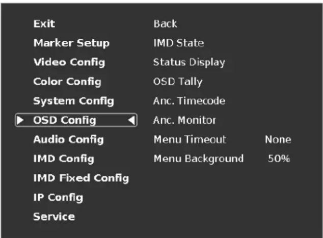
OSD Configuration Submenu
Use the OSD Configuration submenu to select a variety of information to be displayed on the screen.
text_image
Exit Back Marker Setup IMD State Video Config Status Display Color Config OSD Tally System Config Anc. Timecode ► OSD Config Anc. Monitor Audio Config Menu Timeout None IMD Config Menu Background 50% IMD Fixed Config IP Config ServiceOSD Configuration Submenu
■ IMD State
Use this setting to enable or disable the IMD text display. This setting affects both the fixed string (entered through display menus) and remote IMD text commands.
■ Status Display
Use this setting to enable or disable status display. When enabled, the current video input standard is displayed on the top left of the screen. When disabled, status is only displayed for 2 seconds when the monitor is powered on, when an input is applied, or when the input video standard changes. The status display reads "No Input" when no video input is present.

text_image
CH1 HDSDI/SDI NO INPUTStatus Display
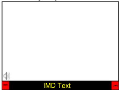
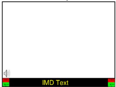
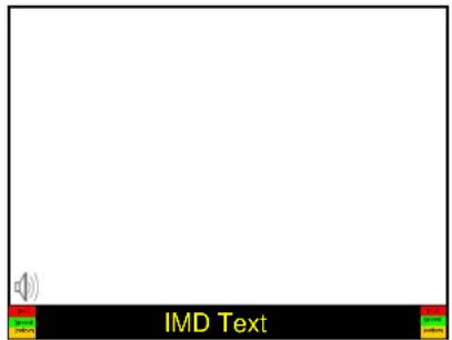
OSD Tally
Use this setting to choose how tally is displayed on the screen. The available OSD Tally options depend on the Tally Source selected in the IMD Configuration submenu.
When the Tally Source is set to Standard (contact closure), OSD Tally can be set to Off, RGY, RG, or GR:
- Off On-screen tally is disabled
• RGY Red, yellow, or green tally signals are indicated at both the bottom left and bottom right corners of the screen. Two or three colors are shown simultaneously by subdividing each tally indicator
• RG Red tally is shown at the bottom left of the screen, and green is shown at the bottom right.
• GR Green tally is shown at the bottom left of the screen, and red is shown at the bottom right.
The following diagrams show RGY, RG, and GR OSD Tally modes:
text_image
IMD TextRGY mode: single color activated
text_image
IMD TextRGY mode: two colors activated
text_image
IMD TextRGY mode: three colors activated
text_image
00:00:00:00 IMD TextRG Mode: both colors activated
text_image
00:00:00:00 IMD TextGR Mode: both colors activated
When the Tally Source is set to TSL/MEI 422, OSD Tally can be set to Off or IMD:
- Off On-screen tally is disabled
- IMD Red, yellow, and green tally is displayed according to the protocol commands. Green, red, and yellow colors are shown individually on either the bottom left or right of the screen.
■ Anc. Time Code
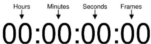
Use this setting to enable time code display on the screen. Time code is de-embedded from the vertical ancillary data (VANC) within the HD/SDI signal. Two types of time code can be selected to display on the screen: LTC (linear time code) or VITC (vertical interval time code).
The position of the time code display varies based on the aspect ratio setting and presence of IMD text
text_image
Hours Minutes Seconds Frames 00:00:00:00Time Code display
Anc. Monitor
Use the Ancillary Monitor menu option to enable or disable on screen audio, closed caption and timecode presence indicators. When enabled, Audio, CC608, CC708, LTC and VITC indicators are shown on the screen. A green circle will appear next to each data type if it is present in the SDI stream.
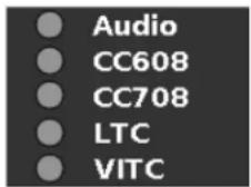
Ancillary Monitor with input signal with no ancillary data
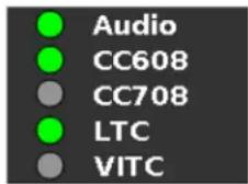
Ancillary Monitor with input signal with Audio, 608 CC and LTC timecode.
Menu Timeout
Select how long the Menu will remain active on the screen. Choose between None (no Menu timeout) to 30 Seconds in 5 second increments.
Menu Background
Select the transparency of the Menu Background. Choose between Off (Menu background is completely transparent), 50% or Solid (video behind the menu cannot be seen).
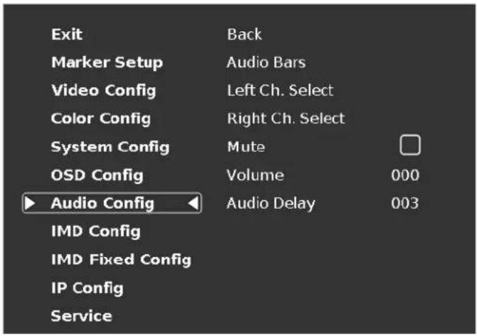
Audio Config Submenu
Use the Audio Configuration submenu to configure Audio channel selection for the headphone jack, audio level and on screen audio display.
text_image
Exit Back Marker Setup Audio Bars Video Config Left Ch. Select Color Config Right Ch. Select System Config Mute OSD Config Volume 000 ► Audio Config Audio Delay 003 IMD Config IMD Fixed Config IP Config ServiceAudio Configuration Submenu
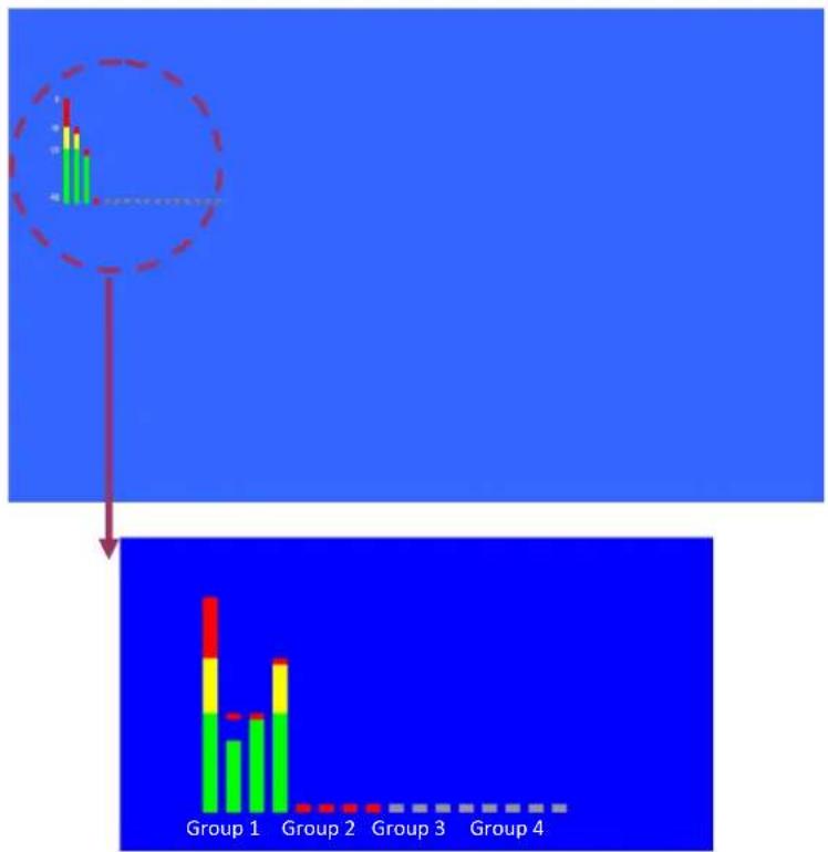
■ Audio Bars
This monitor provides audio level indicators for SDI streams with embedded audio. Support for up to 16 channels (labeled as Groups 1, 2, 3 and 4) is provided.
bar
| Group | Value | |---|---| | Group 1 | 100 | | Group 2 | 50 | | Group 3 | 25 | | Group 4 | 10 |Audio groups 1-4 shown on the screen
Left Ch. Select
Use this setting to select which of the 16 possible channels you would like to monitor on the Left side of the stereo output.
Right Ch. Select
Use this setting to select which of the 16 possible channels you would like to monitor on the Right side of the stereo output.
Mute
The Mute function disables audio output from Headphone output on the monitor. This will NOT control the Line Out level of the monitor, only the Headphone output.
Volume
The Volume control determines the output level for the Headphone out on the monitor. This will NOT control the Line Out level of the monitor, only the Headphone output.
Audio Delay
The Audio Delay function applies a delay to the Audio Metering and audio output. Use the function to select a delay between 000 and 015 (in terms of fields, or frames if the signal is progressive).
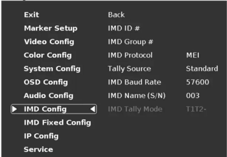
IMD Config Submenu
The QVW-1708-Q features an In-Monitor Display (IMD) with the ability to display on-screen text and tally in three colors. IMD text, color, and alignment can be assigned to each input locally using menu options (see below).
Alternately, IMD text and tally can be remotely controlled via the RS-422/485 serial interface using several industry-standard protocols, including TSL v4.0 and Image Video. Multiple QVW-1708-Q monitors can be looped together and each addressed individually via the protocol. All menu features of the QVW-1708-Q can also be controlled via the embedded MEI Remote page.
Use the IMD Configuration submenu to configure various IMD parameters as described below. IMD State can be enabled / disabled through the OSD Config submenu.
text_image
Exit Back Marker Setup IMD ID # Video Config IMD Group # Color Config IMD Protocol MEI System Config Tally Source Standard OSD Config IMD Baud Rate 57600 Audio Config IMD Name (S/N) 003 ▶ IMD Config IMD Tally Mode T1T2- IMD Fixed Config IP Config ServiceIMD Configuration Submenu
IMD ID #
The IMD ID # identifies each screen to the controlling device. When using the TSL protocol, the ID # of each screen should be manually set in conjunction with the controlling device. When using the Image Video protocol, the ID # may be set automatically by the controlling device, after each IMD is initially identified by IMD Name. Available ID #s are 000-254.
IMD Group #
Each screen can be assigned an IMD Group # when using the Marshall protocol. Available Group #s are 01-254.
IMD Protocol
Use the IMD Protocol menu option to choose the protocol with which the QVW-1708-Q receives remote commands. Currently, four protocols are available. Contact Marshall Electronics for the latest protocol compatibility.
MEI
Use the MEI protocol setting when controlling the QVW-1708-Q using the Marshall Network Controller box. This protocol allows remote control of all features on the QVW-1708-Q, including marker setup, video configuration, system configuration, and image adjustments (brightness, contrast, etc.). The IMD #, IMD Group #, and Baud Rate parameters must be set in conjunction with the Network Controller Box.
TSL v4.0
Use the TSL v4.0 protocol setting when controlling the IMD from a TSL tally controller, or other controlling device which utilizes the TSL v4.0 protocol. The IMD # must be set for each screen in conjunction with the controlling device.
Image Video
Use the Image Video protocol setting when controlling the IMD from an Image Video tally controller (e.g. TSI-1000) or other controlling device which utilizes the Image Video protocol. The IMD #, IMD Name(S/N), and Baud Rate parameters must be set for each screen in conjunction with the controlling device.
Tally Source
The QVW-1708-Q OSD tally can be controlled in a variety of different ways. Use the Tally Source setting to choose how tally is controlled:
Standard
Use the Standard setting to control tally via contact closure on the HD-15 tally interface.
Image Video HW
Use the Image Video HW setting to control Image Video tally states via contact closure on the HD-15 tally interface. Contact closure of the Red pin corresponds to Image Video Tally 1, and the Green pin maps to Image Video Tally 2. Contact closure (ground) corresponds to a LOW state, and open circuit corresponds to a HIGH state. This mode requires the IMD Tally Mode parameter to be set. Consult Image Video documentation for further information.
Image Video 422
Use the Image Video 422 setting to control Image Video tally states via the Image Video serial protocol. OSD tally will be disabled in this mode, as Image Video tally states are manifested in the text color and other parameters. This mode requires the IMD Tally Mode parameter to be set. Consult Image Video documentation for further information.
Standard + IV422
Use the Image Video 422 setting to control Image Video tally states via the Image Video serial protocol, while controlling OSD tally using contact closure on the HD-15 tally interface. This mode requires the IMD Tally Mode parameter to be set. Consult Image Video documentation for further information.
TSL/MEI 422
Use the TSL/MEI 422 setting to control OSD tally via the TSL or Marshall serial protocols.
IMD Baud Rate
Use this setting to choose the baud rate. The baud rate must be set in conjunction with the controlling device. Available baud rates are 300, 600, 1200, 2400, 4800, 9600, 19200, 38400, 57600, 115200. The TSL v4.0 protocol is fixed at 38400 bauds for correct functionality, but this can be changed on the monitor for custom purposes.
IMD Name (S/N)
Use this setting to assign a name to each screen when using the Image Video or Marshall-IV protocols. The IMD name is equivalent to the Image Video serial number and is used by the Image Video controlling device to identify each screen. The default IMD Name(S/N) is "M00000." It is recommended to maintain this naming scheme in order to avoid serial number conflicts with other Image Video devices on the same serial bus. Each name can be up to 16 ASCII characters.
Press RotoMenu™ knob to edit the IMD Name. Rotate the RotoMenu™ knob to move the cursor. Press the RotoMenu™ knob with the cursor on the character to be changed, then rotate the knob to scroll through the character set. Press the RotoMenu™ knob to choose a character.
IMD Tally Mode
Use this setting when using Image Video tally control. Choose one of the following settings, in conjunction with the Image Video controlling device. T1, T2, T1T2, T2T1, T1-, T2-, T1T2-, T2T1-. Consult Image Video documentation for further information.
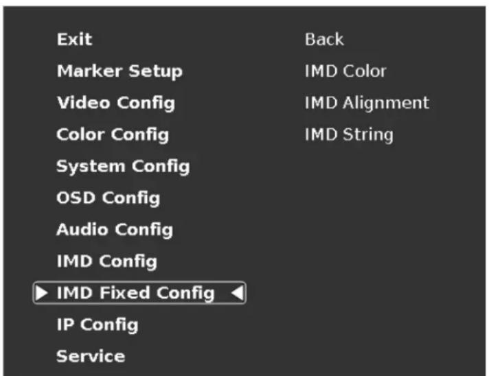
IMD Fixed Config Submenu
text_image
Exit Back Marker Setup IMD Color Video Config IMD Alignment Color Config IMD String System Config OSD Config Audio Config IMD Config ► IMD Fixed Config ◀ IP Config ServiceIMD Fixed Configuration Submenu
■ IMD Color
Use this setting to choose the color of the IMD Fixed String text (see below). Available colors are red, green, and yellow. This setting does not affect text color when using IMD text via the Image Video or TSL v4.0 protocols (text color is set via the protocols).
■ IMD Alignment
Use this setting to choose the horizontal alignment of the IMD text. IMD text can be justified on the left, center or right of the screen. This setting is overridden when using IMD text via the Image Video protocol (alignment is set via Image Video protocol).
■ IMD String
Use this setting to display static IMD text on the screen. This setting is used to enter IMD text locally, when a serial protocol is not used for remote control. The IMD Fixed String is saved after power cycle. The IMD Fixed String will be overridden by serial protocol commands.
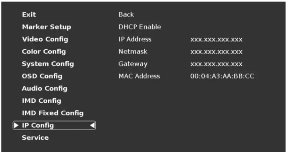
IP Config Submenu
The IP CONFIGURATION submenu is intended to configure settings for access to the embedded Network Control Platform on the QVW monitor series. Please consult with your network administrator to ensure compatibility with your network.
text_image
Exit Back Marker Setup DHCP Enable Video Config IP Address xxx.xxx.xxx.xxx Color Config Netmask xxx.xxx.xxx.xxx System Config Gateway xxx.xxx.xxx.xxx OSD Config MAC Address 00:04:A3:AA:BB:CC Audio Config IMD Config IMD Fixed Config ► IP Config ServiceIMD Fixed Configuration Submenu
DHCP Enable
Use DHCP to set the IP Address, Netmask and Gateway automatically.
IP Address
Use this field to manually set an IP Address for a particular monitor. If you enable DHCP, this will be automatically set for you based on your current Network settings.
Netmask
Use this field to set the appropriate Netmask compatible with your network. If you enable DHCP, this will be automatically set for you based on your current Network settings.
Gateway
Use this field to set the appropriate Gateway compatible with your network. If you enable DHCP, this will be automatically set for you based on your current Network settings.
MAC Address
The MAC address is an internal fixed address for each individual monitor. You may wish to refer to this value when setting up your network.
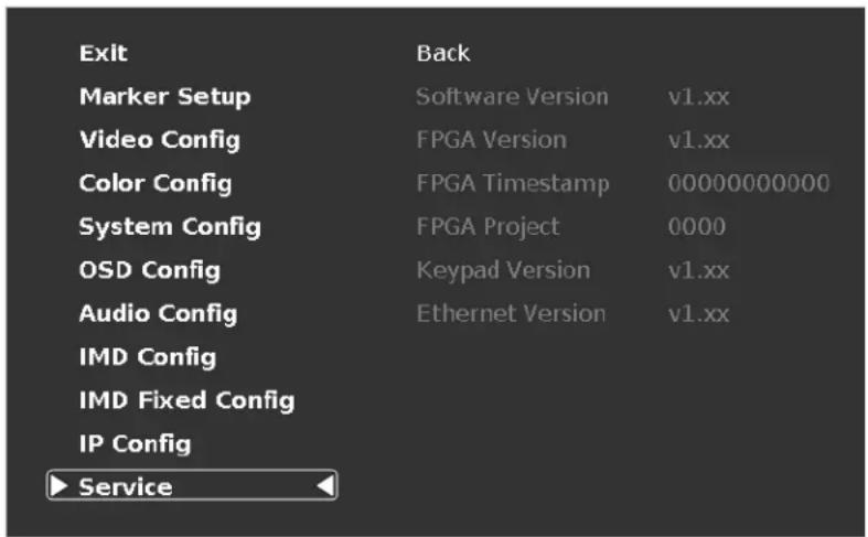
Service Submenu
Software Version Display
This submenu will give you access to Software versions for each of the key components of the system.
text_image
Exit Back Marker Setup Software Version v1.xx Video Config FPGA Version v1.xx Color Config FPGA Timestamp 00000000000 System Config FPGA Project 0000 OSD Config Keypad Version v1.xx Audio Config Ethernet Version v1.xx IMD Config IMD Fixed Config IP Config ► ServiceService Menu
Monitor Specifications
Panel Specifications
Screen Size 17.3"
Screen Resolution 1920 x 1080
Brightness 400 cd/m
Contrast Ratio 600:1
Burn-In Warning
The QVW-1708-Q uses a high quality LCD panel.
However, if a static image is left on the screen for 48 hours, there may be a 10 to 20 minute recovery period for the panel. During recovery, a very faint image may be retained on the display. Put up a white image for 30 minutes to eliminate the retained image.
Connectors
Modular Inputs
2 x Input Module Slots
Video Inputs / Outputs
Optional Modules Available - 3G-SDI (2 x Input / Output)
Power Input
4-Pin XLR
Tally / GPI Interface
HD-15 Female connector
RS-422/485 Interface
2 x RJ12 (Modular 6P6C)
1 x RJ12 (Host port)
Ethernet (Remote Control Page)
1 x RJ45
Electrical
Voltage Requirement 12 VDC
Power Consumption 5.0 A
Included Power Supply V-PS12V-5A-XLR
Tally / GPI Connector
| G | R | Y | |
| 1 | 1 | 2 | 3 |
| 2 | 6 | 7 | 8 |
| 3 | 11 | 12 | 13 |
| 4 | 5 | 10 | 15 |
| GRND 4;9;14 | |||
Connect the corresponding pins (under G,R,Y), and execute a dry contact closure by connecting it to either of the GRND pins listed.
Mechanical
Weight 9.35 Lbs
Operating Temperature 0^ C – 35^ C
Storage Temperature -10^ C – 50^ C
Dimensions
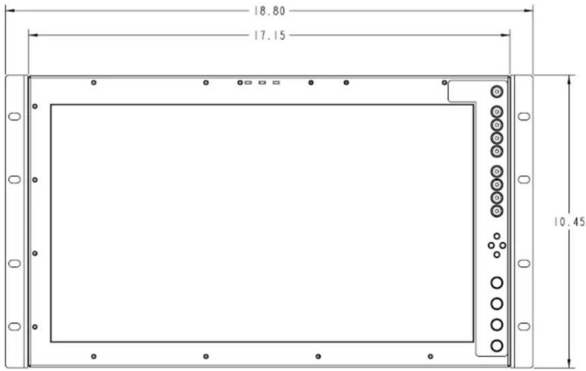
text_image
18.80 17.15 10.45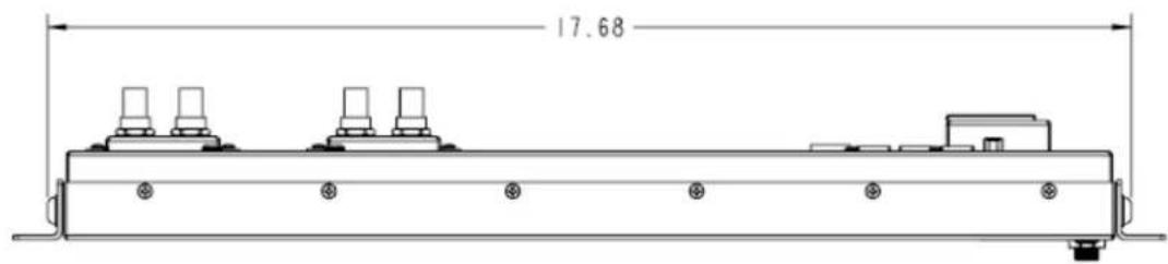
text_image
17.68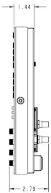
text_image
1.44 2.79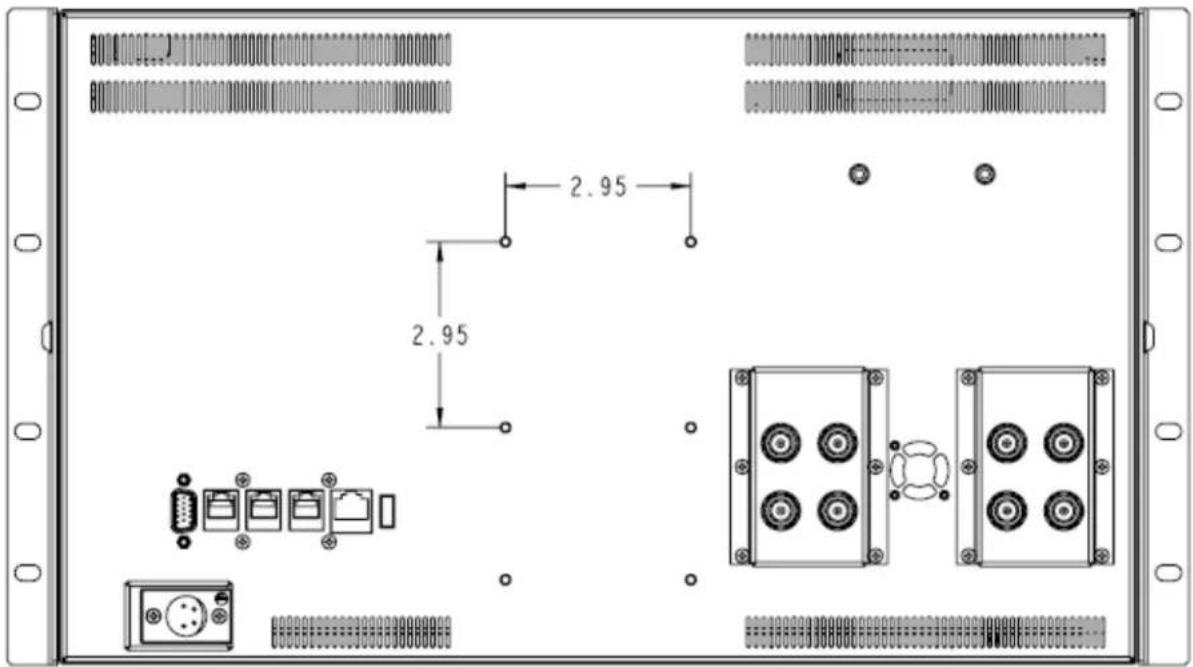
text_image
2.95 2.95
text_image
17.15 10.40 .75 4.91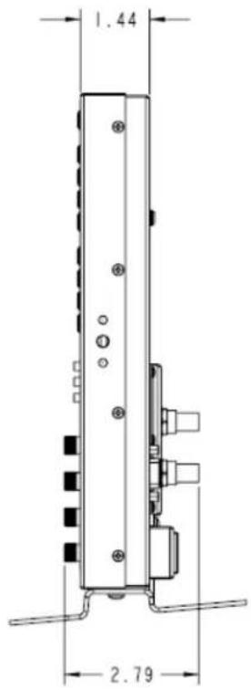
text_image
1.44 2.79Warranty
Marshall Electronics warranties to the first consumer that this QVW-1708 LCD monitor will, under normal use, be free from defects in workmanship and materials, when received in its original container, for a period of one year from the purchase date. This warranty is extended to the first consumer only, and proof of purchase is necessary to honor the warranty. If there is no proof of purchase provided with a warranty claim, Marshall Electronics reserves the right not to honor the warranty set forth above. Therefore, labor and parts may be charged to the consumer. This warranty does not apply to the product exterior or cosmetics. Misuse, abnormal handling, alterations or modifications in design or construction void this warranty. It is considered normal for a minimal amount of pixels, not to exceed three, to fail on the periphery of the display active viewing area. Marshall Electronics reserves the option to refuse service for display pixel failure if deemed unobtrusive to effective use of the monitor by our technicians. No sales personnel of the seller or any other person is authorized to make any warranties other than those described above, or to extend the duration of any warranties on behalf of Marshall Electronics, beyond the time period described above. Due to constant effort to improve products and product features, specifications may change without notice.