NK182-85CB - Security Camera Lorex - Free user manual and instructions
Find the device manual for free NK182-85CB Lorex in PDF.

User questions about NK182-85CB Lorex
0 question about this device. Answer the ones you know or ask your own.
Ask a new question about this device
Download the instructions for your Security Camera in PDF format for free! Find your manual NK182-85CB - Lorex and take your electronic device back in hand. On this page are published all the documents necessary for the use of your device. NK182-85CB by Lorex.
USER MANUAL NK182-85CB Lorex
User Manual N841 Series

text_image
4K Ultra HD NVRUser Manual N841 Series
Thank you for purchasing this product. Lorex Corporation is committed to providing our customers with quality, reliable security solution.
This manual refers to the following models:
N841A81
N841A82
For the latest online manual, downloads and product updates, and to learn about our complete line of products, please visit our website at:
a high
lorex.com

WARNING
RISK OF ELECTRIC SHOCK DO NOT OPEN

WARNING: TO REDUCE THE RISK OF ELECTRIC SHOCK DO NOT REMOVE COVER. NO USER SERVICEABLE PARTS INSIDE.
REFER SERVICING TO QUALIFIED SERVICE PERSONNEL.

The lightning flash with arrowhead symbol, within an equilateral triangle, is intended to alert the user to the presence of uninsulated "dangerous voltage" within the product's enclosure that may be of sufficient magnitude to constitute a risk of electric shock.

The exclamation point within an equilateral triangle is intended to alert the user to the presence of important operating and maintenance (servicing) instructions in the literature accompanying the appliance.
WARNING: TO PREVENT FIRE OR SHOCK HAZARD, DO NOT EXPOSE THIS UNIT TO RAIN OR MOISTURE.
CAUTION: TO PREVENT ELECTRIC SHOCK, MATCH WIDE BLADE OF THE PLUG TO THE WIDE SLOT AND FULLY INSERT.
Table of contents
1 Important Safeguards .... 1
1.1 General Precautions.... 1
1.2 Installation 1
1.3 Service 3
1.4 Use 3
2 Package Contents.... 4
3 Recorder Overview 5
3.1 Front Panel 5
3.2 Back Panel 5
4 Basic System Setup.... 7
4.1 STEP 1: Connect cameras.... 7
4.2 STEP 2: Connect router 7
4.3 STEP 3: Connect mouse 7
4.4 STEP 4: Connect monitor 8
4.5 STEP 5: Connect power 8
4.6 STEP 6: Upgrade Firmware to Latest Version (If Available) 8
4.7 Quick Access to System Information.... 9
4.8 Connecting Cameras to the Local Area Network (LAN) .....10
5 Camera Installation....13
5.1 Installation Tips 13
5.2 Installing Cameras 13
5.3 Connecting Camera Extension Cables 14
6 Using the Mouse ....15
7 Setting the Date & Time ....16
8 Using the On-Screen Display....18
8.1 Navigation Bar....18
8.2 Quick Menu 18
8.3 Camera Toolbar....19
8.4 On-Screen Keyboards 20
8.5 Camera Image Settings 21
9 Recording 23
9.1 Video Recording Types....23
9.2 Configuring Recording Quality 23
9.3 Setting the Recording Schedule 24
9.4 Setting up Scheduled or Manual Recording 25
9.5 Configuring Hard Drive Overwrite 27
10 Playback....28
10.1 Playing Back Video from the Hard Drive....28
10.2 Playback Controls....28
10.3 Area Search ....30
10.4 Video Clip Backup....32
10.5 Playing Back Video from a USB Drive 33
11 Backup....35
11.1 Formatting the USB Flash Drive....35
11.2 Backing Up Video....36
11.3 Using Video Clip Backup 37
11.4 Viewing Backed Up Files 37
11.4.1 Viewing Backed Up Files on PC 37
11.4.2 Viewing Backed Up Files on Mac....38
11.4.3 Lorex Player Controls....39
12 Motion Detection ..... 42
12.1 Status Icons 42
12.2 Configuring Motion Detection 42
13 Active Deterrence....45
13.1 Automatic Deterrence Settings ....45
13.2 Manually Activate Deterrence Features....47
14 Smart Motion Detection....48
14.1 Ensuring Accurate Person & Vehicle Detection 48
14.2 Configuring Person & Vehicle Detection 49
14.3 Searching for Person & Vehicle Detection Events (Smart Search)....51
15 Managing Passwords and User Accounts ....53
15.1 User Accounts 53
15.1.1 Changing Passwords 53
15.1.2 Adding Users....54
15.1.3 Modifying Users 55
15.1.4 Deleting Users 56
15.2 Account Groups 56
15.2.1 Adding Groups....56
15.2.2 Modifying Groups 57
15.2.3 Deleting Groups 57
16 Using the Main Menu....59
16.1 Main Menu Overview 59
16.2 Camera Menu 59
16.2.1 Viewing Camera Status 59
16.2.2 Camera Firmware Versions 60
16.2.3 Upgrading Camera Firmware 61
16.2.4 Configuring Snapshot Recording Settings 62
16.2.5 Configuring Video Overlay Settings 63
16.2.6 Creating Custom Channel Names 64
16.3 Information Menu....65
16.3.1 Hard Drive Information....65
16.3.2 Recording Information....66
16.3.3 Version Information 67
16.3.4 Event Information 68
16.3.5 Online Users....69
16.3.6 Network Load 70
16.3.7 Network Test 71
16.3.8 BPS 72
16.3.9 System Log 73
16.4 Settings Menu 74
16.4.1 Selecting DHCP or Static IP Address (TCP/IP) .....74
16.4.2 Configuring System Ports (Connection)....75
16.4.3 Configuring IP Filter 76
16.4.4 Configuring Email Alerts....77
16.4.5 FTP (Advanced) 79
16.4.6 Configuring Switch Settings (Advanced) 80
16.4.7 P2P Setting 81
16.4.8 Configuring Video Loss Settings 81
16.4.9 Configuring Hard Drive Warnings 82
16.4.10 Configuring Network Warnings 83
16.4.11 Configuring Pre-Recording 84
16.4.12 Formatting the Hard Drive 85
16.4.13 Configuring Hard Drive Type....86
16.4.14 Configuring Holidays 87
16.4.15 Configuring General System Settings 88
16.4.16 Setting the Monitor Resolution (Display) 89
16.4.17 Configuring Sequence Mode....91
16.4.18 Saving Your System Configuration to a USB Thumb Drive .....92
16.4.19 Restore Default Settings 93
16.4.20 Upgrading Firmware Manually....94
16.4.21 Automatic Firmware Upgrades 95
16.5 Shutdown....96
17 Connecting Remotely using the Lorex Home Mobile App....97
18 Smart Home & Voice Assistance 98
19 Pan/Tilt/Zoom (PTZ) Cameras 99
19.1 Connecting PTZ Cameras to the Recorder....99
19.2 Basic PTZ Controls 100
19.3 Advanced PTZ Controls.... 100
19.4 Presets 101
19.5 Tours 102
19.6 Patterns 102
19.7 AutoScan 102
20 Connecting Audio Devices 104
21 Replacing the Hard Drive 106
21.1 Removing the Hard Drive.... 106
21.2 Installing a New Hard Drive.... 109
22 DDNS Setup (Advanced).... 112
22.1 STEP 1: Port Forwarding 112
22.2 STEP 2: Create a Lorex Account 112
22.3 STEP 3: Activate Your Warranty 113
22.4 STEP 4: Sign Up for a DDNS Account 113
22.5 STEP 5: Enable DDNS on the Recorder 114
23 Troubleshooting..... 116
24 Technical Specifications 118
24.1 General 118
24.2 Inputs/Outputs 118
24.3 Display.... 118
24.4 Recording 118
24.5 Playback 118
24.6 Storage.... 118
24.7 Special Features 118
24.8 Smart Home 119
24.9 Connectivity 119
24.10 Additional Specifications 119
25 Notices 120
25.1 FCC/IC 120
25.2 CE 120
25.3 Modification 120
Table of contents
| 25.4 | RoHS | 120 |
| 25.5 | ICES-003 | 120 |
Important Safeguards1
In addition to the careful attention devoted to quality standards in the manufacturing process your product, safety is a major factor in the design of every instrument. However, safety is responsibility too. This sheet lists important information that will help to ensure your enjoymer proper use of the product and accessory equipment. Please read them carefully before operati and using your product.
1.1 General Precautions
- All warnings and instructions in this manual should be followed.
- Remove the plug from the outlet before cleaning. Do not use liquid aerosol detergents. U water-dampened cloth for cleaning.
- Do not use this product in humid or wet places.
- Keep enough space around the product for ventilation. Slots and openings in the storage net should not be blocked.
- It is highly recommended to connect the product to a surge protector to protect from da caused by electrical surges. It is also recommended to connect the product to an uninten ble power supply (UPS), which has an internal battery that will keep the product runnin the event of a power outage.

CAUTION
Maintain electrical safety. Power line operated equipment or accessories connected to this product should bear UL listing mark or CSA certification mark on the accessory itself and should not be modified so as to defe safety features. This will help avoid any potential hazard from electrical shock or fire. If in doubt, contact q service personnel.
1.2 Installation
- Read and Follow Instructions: All the safety and operating instructions should be read before the product is operated. Follow all operating instructions.
- Retain Instructions: The safety and operating instructions should be retained for future reference.
- Heed Warnings: Comply with all warnings on the product and in the operating instructions.
- Polarization: Do not defeat the safety purpose of the polarized or grounding-type plug. A polarized plug has two blades with one wider than the other.
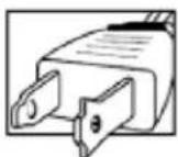
A grounding type plug has two blades and a third grounding prong.

The wide blade or the third prong are provided for your safety.
If the provided plug does not fit into your outlet, consult an electrician for replacement obsolete outlet.
-
Power Sources: This product should be operated only from the type of power source indicated on the marking label. If you are not sure of the type of power supplied to your consult your video dealer or local power company. For products intended to operate from tery power, or other sources, refer to the operating instructions.
-
Overloading: Do not overload wall outlets or extension cords as this can result in the risk of fire or electric shock. Overloaded AC outlets, extension cords, frayed power cords, damage or cracked wire insulation, and broken plugs are dangerous. They may result in a shock hazard. Periodically examine the cord, and if its appearance indicates damage or deteriorating insulation, have it replaced by your service technician.
-
Power-Cord Protection: Power supply cords should be routed so that they are not likely to be walked on or pinched by items placed upon or against them. Pay particular attention cords at plugs, convenience receptacles, and the point where they exit from the product.
-
Surge Protectors: It is highly recommended that the product be connected to a surge proctor. Doing so will protect the product from damage caused by power surges. Surge prot should bear the UL listing mark or CSA certification mark.
-
Uninterruptible Power Supplies (UPS): Because this product is designed for continuous, 247 operation, it is recommended that you connect the product to an uninterruptible power ply. An uninterruptible power supply has an internal battery that will keep the product r in the event of a power outage. Uninterruptible power supplies should bear the UL listir mark or CSA certification mark.
-
Ventilation: Slots and openings in the case are provided for ventilation to ensure reliable operation of the product and to protect it from overheating. These openings must not be bld covered. The openings should never be blocked by placing the product on a bed, sofa, other similar surface. This product should never be placed near or over a radiator or heater. This product should not be placed in a built-in installation such as a bookcase or less proper ventilation is provided and the product manufacturer's instructions have been followed.
-
Attachments: Do not use attachments unless recommended by the product manufacturer a they may cause a hazard.
-
Water and Moisture: Do not use this product near water — for example, near a bath tub, wash bowl, kitchen sink or laundry tub, in a wet basement, near a swimming pool and
-
Heat: The product should be situated away from heat sources such as radiators, heat registers, stoves, or other products (including amplifiers) that produce heat.
-
Accessories: Do not place this product on an unstable cart, stand, tripod, or table. The product may fall, causing serious damage to the product. Use this product only with a cart, start pod, bracket, or table recommended by the manufacturer or sold with the product. Any 1ing of the product should follow the manufacturer's instructions and use a mounting accer recommended by the manufacturer.

-
Camera Extension Cables: Check the rating of your extension cable(s) to verify compliant with your local authority regulations prior to installation.
-
Mounting: The cameras provided with this system should be mounted only as instructed this guide or the instructions that came with your cameras, using the provided mounting brackets.
-
Camera Installation: Cameras are not intended for submersion in water. Not all cameras be installed outdoors. Check your camera environmental rating to confirm if they can be stalled outdoors. When installing cameras outdoors, installation in a sheltered area is required
1.3 Service
-
Servicing: Do not attempt to service this product yourself, as opening or removing covers may expose you to dangerous voltage or other hazards. Refer all servicing to qualified s personnel.
-
Conditions Requiring Service: Unplug this product from the wall outlet and refer servicing to qualified service personnel under the following conditions:
-
When the power supply cord or plug is damaged.
- If liquid has been spilled or objects have fallen into the product.
- If the product has been exposed to rain or water.
- If the product has been dropped or the cabinet has been damaged
- If the product does not operate normally by following the operating instructions. Adjustly those controls that are covered by the operating instructions. Improper adjustment of er controls may result in damage and will often require extensive work by a qualified technician to restore the product to its normal operation.
- When the product exhibits a distinct change in performance. This indicates a need for service.
- Replacement Parts: When replacement parts are required, have the service technician verify that the replacements used have the same safety characteristics as the original parts. Use placements specified by the product manufacturer can prevent fire, electric shock, or other hazards.
- Safety Check: Upon completion of any service or repairs to this product, ask the service technician to perform safety checks recommended by the manufacturer to determine that the act is in safe operating condition.
1.4 Use
- Cleaning: Unplug the product from the wall outlet before cleaning. Do not use liquid cleaners or aerosol cleaners. Use a damp cloth for cleaning.
- Product and Cart Combination: When product is installed on a cart, product and cart condition should be moved with care. Quick stops, excessive force, and uneven surfaces may cause the product and cart combination to overturn.
- Object and Liquid Entry: Never push objects of any kind into this product through open as they may touch dangerous voltage points or "short-out" parts that could result in a f electric shock. Never spill liquid of any kind on the product.
- Lightning: For added protection of this product during a lightning storm, or when it is left unattended and unused for long periods of time, unplug it from the wall outlet and discon antenna or cable system. This will prevent damage to the product due to lightning and line surges.
Package Contents2
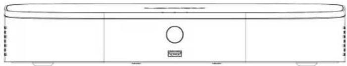
Your security recorder package includes the following components:
natural_image
Line drawing of a rectangular electronic device with a central circular element and mounting feet (no text or symbols)4K Ultra HD Security NVR

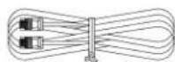
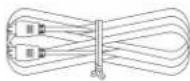
Power Adapter Ethernet Cable USB Mouse HDMI Cable


NOTE
Hard drive size, number of channels, and camera configuration may vary by model. Please refer to your pack for specific details. Check your package to confirm that you have received the complete system, including all ponents shown above.
Recorder Overview3
3.1 Front Panel

text_image
4K Ultra HDNVR 1 2 31. LED Indicators:
- HDD: Glows to indicate hard drive is operating properly. Turns off when there is drive error.
• POWER: Glows to indicate the system is on.
• NETWORK: Glows to indicate the recorder is connected to the Internet for remote access and automatic firmware updates. Turns off when there is no Internet access.
2. Info / Panic Button:
- From live view, press once to open the System Information screen.
-
Press and hold for 3 seconds to activate the warning lights and sirens on all connected terrence cameras.
-
USB Port: Connect a USB mouse (included) to control the system, or a USB flash drive (included) for data backup or manual firmware updates.
3.2 Back Panel

text_image
1 2 3 4 5 6 7- DC 12V: Connect the included power adapter.
- PoE Vidco Inputs: Connect Lorex IP cameras to the system. For a full list of compatibleras, visit lorex.com/compatibility.
- LAN: Connect the included RJ45 Ethernet cable from the recorder to your router for ren connectivity and automatic firmware updates.
- VGA: Connect a VGA monitor (not included) to view the system interface.
5. AUDIO IN/OUT:
- Connect an external microphone to the AUDIO IN port for single-channel audio recordi
- Connect an external speaker to the AUDIO OUT port to hear system audio
-
For full details on connecting external audio devices, see 20 Connecting Audio Devices, page 104.
-
HDMI: Connect to an HDMI monitor or TV (not included) using the included HDMI ca view the system interface.
Recorder Overview3
- USB Port: Connect a USB mouse (included) to control the system, or a USB flash drive (included) for data backup or manual firmware updates.
Basic System Setup4
4.1 STEP 1: Connect cameras
| NOTE |
| This step is for verification of the camera image only. It is recommended to connect cameras to a adapter for this step. The Lorex Setup Wizard that runs at startup will assist you in naming and cameras, so it is also recommended to leave cameras connected until the wizard asks you to install permanent mounting location. |
nearby F
Option 1: Direct Connection to NVR
Test your cameras prior to selecting a permanent mounting location by temporarily connecting cameras and cables to your recorder. Connect the cameras to the recorder using the RJ45 E extension cables provided with your cameras.

natural_image
Two connected devices: a security camera and a network interface (no text or symbols visible)Option 2: Connect Cameras to Local Network
You can also connect your IP cameras to your local network for flexible installations. For see 4.8 Connecting Cameras to the Local Area Network (LAN), page 10.
| NOTE |
| Before selecting a permanent mounting location for your cameras, see 5 Camera Installation, page 13 for important notes and installation tips. |
4.2 STEP 2: Connect router
Connect the recorder to your router using the included Ethernet cable.

natural_image
Two electronic devices connected by a cable, one with a WiFi and the other a network interface (no text or symbols visible)| NOTE |
| To receive automatic firmware updates and enable remote viewing with mobile apps, a high speed tion is required (minimum upload speed of 5Mbps required for 4K viewing; 3.5Mbps for lower res other system features can be used without an Internet connection. |
4.3 STEP 3: Connect mouse
Connect the included mouse to a USB port on the recorder.

natural_image
Diagram showing a computer mouse connected to an Ethernet device via cable (no text or symbols visible)4.4 STEP 4: Connect monitor
Connect the recorder to a monitor using the included HDMI cable (supports up to 4K resol
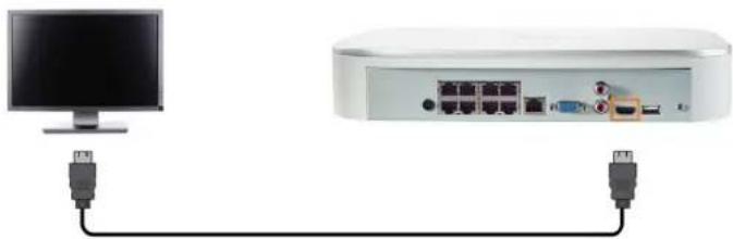
natural_image
Diagram showing a computer monitor connected to a network device via USB cable (no text or symbols visible)OR
Connect the recorder to a monitor using a VGA cable (not included - supports up to 1080 resolution).

natural_image
Two connected devices: a monitor and a network switch, each with a blue VGA terminal (no text or symbols visible)
CAUTION
If you need to switch monitors, make sure you set the recorder to an output resolution supported by the net or before switching. See 16.4.16 Setting the Monitor Resolution (Display), page 89 for details.
4.5 STEP 5: Connect power
Use the included power adapter to connect the recorder to a nearby outlet.
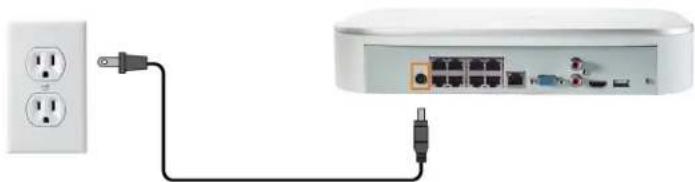
natural_image
Diagram showing connections between a power outlet and a router (no text or symbols visible)4.6 STEP 6: Upgrade Firmware to Latest Version (If Available)
If a firmware upgrade is available, you will be asked to install it once the system starts u ommended to upgrade your system firmware and client software or mobile apps to the latest sion to ensure remote connectivity to the system and support newly-developed features.

NOTE
You must connect your recorder to a router with Internet access in order to get automatic firmware upgrades
If a firmware upgrade is available:
-
After startup, a notification will appear asking you to upgrade the firmware. Click OK to upgrade.
-
Enter the system user name (default: admin) and your secure password, then click OK. Wait for the firmware update to complete. The system will restart once the firmware has been upgraded.

CAUTION
DO NOT POWER OFF THE SYSTEM OR DISCONNECT THE POWER CABLE DURING FIRMWARE INSTALLATION.
4.7 Quick Access to System Information
Perform one of the following actions to bring up the system information window. This wind contains vital system information including the model number, serial number, and device ID.
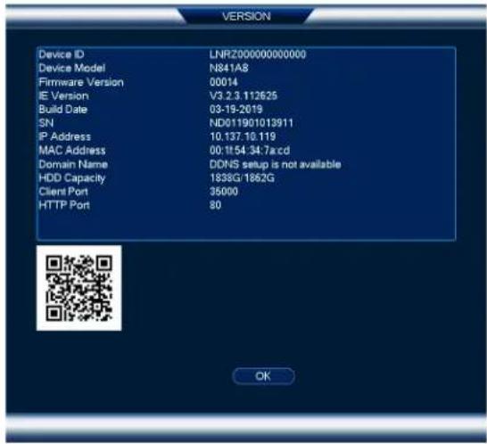
text_image
VERSION Device ID LNRZ000000000000 Device Model N841A8 Firmware Version 00014 IE Version V3.2.3.112625 Build Date 03-19-2019 SN NDD011901013911 IP Address 10.137.10.119 MAC Address 00:1154:34.7acd Domain Name DDNS setup is not available HDD Capacity 1838G/1862G Client Port 35000 HTTP Port 80 OK
NOTE
The QR code shown on this screen can be scanned during mobile setup to enter the system's device ID.
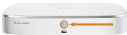
To quickly open a window that displays important system information:
- From the Live View display, right-click to open the Quick Menu, then click Info. OR
- Press the front panel button on the recorder.

NOTE
Do not press and hold the button. The front panel button doubles as a panic button that activates warning and sirens for deterrence cameras if held for 3 seconds.
natural_image
Close-up of a silver electronic device with a circular button and orange arrow pointing to it (no visible text or symbols)4.8 Connecting Cameras to the Local Area Network (LAN)
For flexibility, you may also connect IP cameras to the same Local Area Network (LAN) a NVR instead of connecting them directly to NVR. This is accomplished by connecting the cameras to the same router as the NVR.
For these installations, an external PoE switch (sold separately) or power adapter (sold separate must be used to provide power to each IP camera. You also must add the cameras on the fore they will show a picture on the monitor or be recorded by the NVR.
Follow the steps below to connect the cameras to the NVR over the LAN.
| NOTE |
| Compatible with Lorex HD IP cameras. For a list of compatible cameras, please visit lorex.com/compatibility. |
Step 1 of 2 — Option A: Connecting cameras to your local network using a PoE switch:
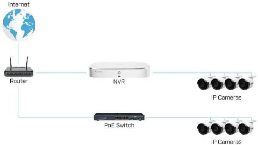
flowchart
graph LR
    A["Internet"] --> B["Router"]
    B --> C["NVR"]
    C --> D["IP Cameras"]
    C --> E["PoE Switch"]
    E --> F["IP Cameras"]
- Connect an Ethernet cable from the LAN port on an external PoE switch (sold separately: lorex.com) to your router using a CAT5c or higher Ethernet cable. Connect the power of the PoE switch and to a power outlet or surge protector.
| NOTE |
| Terminology may vary depending on the model of PoE switch you have. |
- Connect the IP cameras to the PoE switch using the Ethernet extension cables. The PoE will provide power and video transmission the same way as your NVR.
Step 1 of 2 — Option B: Connecting cameras to your local network using power adapters:
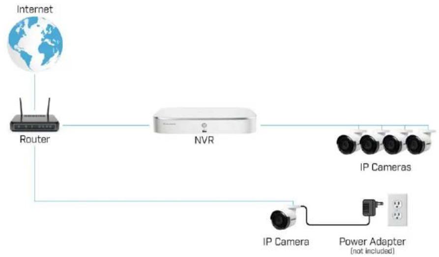
flowchart
graph LR
    A["Internet"] --> B["Router"]
    B --> C["NVR"]
    C --> D["IP Cameras"]
    C --> E["IP Camera"]
    E --> F["Power Adapter (not included)"]
-
Connect each camera to a compatible power adapter (check your camera documentation at lorex.com for compatible power adapters for your cameras).
-
Connect the camera to your router using a CAT5e or higher Ethernet cable.
Step 2 of 2: Add the cameras to your NVR:
- Right-click and select Device Search.

text_image
Camera Registration Device Search IP Address Search Uninitialized Initialize 2 Modify Status IP Address Port Device Model Protocol 1 10.137.10.170 8018 Onvit 2 10.137.10.203 35000 LNR6108 Private Add Ms Add Modify IP Filter None Added Device CH Camera Name Modify Delete Status IP Address Port 1 Backyard 1 ✓ ✗ 10.1.1.128 Port 1 2 Side Yard ✓ ✗ 10.1.1.150 Port 2 3 Backyard 2 ✓ ✗ 10.1.1.129 Port 3 4 Garage ✓ ✗ 10.1.1.151 Port 4 5 Backyard 3 ✓ ✗ 10.1.1.153 Port 5 6 Driveway ✓ ✗ 10.1.1.125 Port 6 7 Front Entrance ✓ ✗ 10.1.1.126 Port 7 Delete Import Export Reconnect IPC- Click Device Search. The system searches the network for compatible cameras.
| NOTE |
| It may take a few minutes after you power up IP cameras for them to appear in your search |
- Check the camera(s) you would like to add.
- Click Add. The Status indicator turns green to show the camera is successfully connected.

NOTE
You can also add a camera to a specific channel by hovering the mouse over an empty channel in split-ser and clicking. Double-click the camera you would like to add, then right-click to exit.
Camera Installation
The following chapter provides general setup instruction and installation tips for security came
| NOTE |
| This section covers connection of cameras to the recorder and general installation tips only. Please umentation that came with your camera or search for your camera model number at lorex.com for specific installation instructions. |
5.1 Installation Tips
General camera installation tips that apply to all camera models. Please review before selecting permanent mounting location for your cameras.
- Test the cameras before permanent installation. Plan where you will route the wiring for 1 camera and where you will aim the camera.
- Point the camera where there is the least amount of obstructions (e.g., tree branches).
- Mount the camera where the lens is away from direct and intense sunlight.
- Plan your cable wiring so that it does not interfere with power lines or telephone lines.
- Secure cabling so that it is not exposed or easily cut.
- Mount the camera in an area that is visible, but out of reach.
- Avoid pointing the camera at a glass window to see outside. This may result in a bright ring in the night vision image, as the light from the night vision LEDs may reflect off
- Adjust the camera angle so that it covers an area with high traffic.
- In "high-risk" locations, have multiple cameras point in the same area. This provides came redundancy if a vandal attempts to damage one of your cameras.
- For outdoor rated cameras, installation in a sheltered location is recommended to ensure the camera lens remains clear of rainwater and other precipitation.
5.2 Installing Cameras
- Mount the cameras to the desired mounting surface according to the instructions that cam with the cameras (visit lorex.com for the most up-to-date documentation). Choose a firm mounting surface that can support the full weight of the camera.
| NOTE |
| If you wish to mount cameras to drywall, it is recommended to use the included drywall anch |
- Adjust the camera stand to ensure that the camera has a satisfactory view of the area y would like to monitor. Stand configuration depends on the mounting surface you have ch (see below for suggested stand configurations).

text_image
LOREX Wall Mount Ceiling Mount
NOTE
Counter / table top mounting is not recommended if you are planning to utilize Person & Vehicle detection due to limited accuracy. Please refer to 14.1 Ensuring Accurate Person & Vehicle Detection, page 48 for recommended camera angling to ensure accurate detection.
5.3 Connecting Camera Extension Cables
It is recommended to connect your cameras directly to the NVR. This is because the NVR Power over Ethernet (PoE) ports that are used to transmit video and audio, as well as prov power to the camera without the need for a power adapter.
You can also connect cameras to a network switch or router (see 4.8 Connecting Cameras t Local Area Network (LAN), page 10for details). If your switch does not support PoE, or you connecting cameras to a router, you will require a power adapter for each camera (sold sep Refer to your camera's documentation at lorex.com for the correct power adapter to use.

text_image
Diagram showing cable connection between a device and its internal components, labeled with numbered parts.- Connect the camera to the included Ethernet extension cable.
- Connect the other end of the Ethernet extension cable to one of the PoE ports on the of the NVR.
Using the Mouse6
The mouse is the primary control device for the system. Connect the included mouse to the port on the front or rear panel.
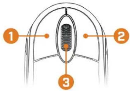
text_image
1 2 31. Left-button:
- In live view, while in a split-screen display mode, click an individual channel to view full-screen. Click again to return to the split-screen display mode. - While navigating menus, click to open a menu option.
2. Right-button:
- During live view, right-click anywhere on the screen to open the Quick Menu. - Within system menus, right-click to exit menus.
- Scroll wheel: In live view, use the scroll wheel to zoom in/out.
Setting the Date & Time
| CAUTION |
| It is highly recommended to set the date and time when first setting up your system. Inaccurate time stamps may render your footage unusable for court evidence. |
| NOTE |
| This chapter covers setting system date and time only. See the references below for full instructions submenus shown below: • General: Scc 16.4.15 Configuring General System Settings, page 88. • Holiday: Scc 16.4.14 Configuring Holidays, page 87. |
To set the date and time:
-
From the Live View display, right-click to open the Quick Menu, then click Main Menu
-
Click 📄, then click SYSTEM. Click the GENERAL tab on the side panel, then click Date & Time on the top panel.
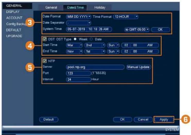
text_image
GENERAL DISPLAY ACCOUNT Config Backu DEFAULT UPGRADE 3 Date Format MM DD YYYY Time Format 12-HOUR Date Separator System Time 05-07-2019 10:18:26 AM to GMT-05.00 OK 4 DST DST Type Week Date Start Time Mar 2nd Sun 02:00 AM End Time Nov 1st Sun 02:00 AM 5 NTP Server pool.ntp.org Manual Update Port 123 (1~65535) Interval 24 Hour Default OK Cancel Apply SYSTEM- Under System Time, enter the current time and select your time zone. Then, click OK.
- Check the DST check box to enable auto Daylight Savings Time updates.
| NOTE |
| ·You can adjust the Start Time and End Time for Daylight Savings Time if the default settings do not match your region. ·Under DST Type, select Week to set the start and end time based on a day and week (e.g. 2nd Sunday in March), or select Date to set the start and end time to a specific date. |
- (Optional) Check the NTP check box to sync your system with an Internet time server. Manual Update to instantly update the time.

NOTE
- Your system must have a constant connection to the Internet to use NTP.
-
(Advanced) You can enter a custom NTP server under Server and Port, and you can select how often the system will sync the time using Interval.
-
Click Apply to save changes.
Using the On-Screen Display
Use the system's on-screen display to navigate menus and configure options and settings.
| NOTE |
| To access the on-screen display, you must connect the included mouse and a monitor (not included Sec 4 Basic System Setup, page 7 for full instructions. |
to the 1
8.1 Navigation Bar
The Navigation Bar along the bottom of the recorder's Live View display allows you to act the Main Menu and control basic functions of the recorder.
To show the Navigation Bar:
- Hover the mouse pointer near the bottom of the Live View screen.

text_image
1 2 3 4 5 6 7 8 9 10 11 12 13 14 15- Main Menu: See 16 Using the Main Menu, page 59 for full instructions on using the Main Menu.
- Collapse Navigation Bar
- Viewing Modes: Select how many channels are shown on screen during live viewing.
- Sequence Mode: Start or stop Sequence Mode. In Sequence Mode, the system display will automatically cycle through connected channels every few seconds.
- Pan/Tilt/Zoom: Control and configure settings for Pan-Tilt-Zoom (PTZ) cameras. For full instructions on connecting and using PTZ cameras, see 19 Pan/Tilt/Zoom (PTZ) Cameras, page 99.
- Camera: Click to open camera image settings. For full details, see 8.5 Camera Image Settings, page 21.
- Playback: Opens the Playback Menu. This allows you to search for video recordings save on the recorder's hard drive. For details on using the Playback menu, see 10 Playback, 28.
- Alarm Status: View alarms in progress. See 16.3.4 Event Information for details.
- Channel Info: Click to access status information about connected cameras.
- Remote Device Search: Manage IP cameras over the network.
- Network: View and configure network options, including setting a dynamic or static IP dress. For full instructions on configuring network options, see 16.4.1 Selecting DHCP or Static IP Address (TCP/IP), page 74.
- Hard Drive Manager: Configure hard drive read/write options (see 16.4.13 Configuring Hard Drive Type, page 86 for details) or format drives (see 16.4.12 Formatting the Hard Drive, page 85 for details).
- USB Manager: Click to access options for connected USB thumb drives (not included). can backup video, logs, or system configurations and install firmware upgrades.
- System Upgrade: Check for firmware upgrades. The system must be connected to the Ir to check for or receive updates.
- Warning Light & Siren — Deterrence Cameras Only: Click to activate warning lights and sirens for all connected deterrence cameras. Click again to deactivate.
8.2 Quick Menu
The Quick Menu gives you quick access to functions which can also be accessed using the gation Bar.
To open the Quick Menu:
• Right-click anywhere on the Live View screen.
text_image
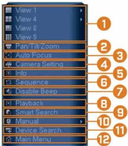
View 1 View 4 View 8 View 9 Pan/Tilt/Zoom Auto Focus Camera Setting Info Sequence Disable Beep Playback Smart Search Manual Device Search Main Menu-
Viewing Modes: Select how many channels are shown on screen during live viewing.
-
Pan/Tilt/Zoom: Control and configure settings for Pan-Tilt-Zoom (PTZ) cameras. For full instructions on connecting and using PTZ cameras, see 19 Pan/Tilt/Zoom (PTZ) Cameras, page 99.
-
AutoFocus: Access zoom/focus controls for auto-focus cameras (not included).
-
Camera Setting: Configure image settings for cameras. For full details, see 8.5 Camera Image Settings, page 21.
-
Info: Displays system information, such as model number, device ID, IP address, etc.
-
Sequence: Start or stop Sequence Mode. In Sequence Mode, the system display will automatically cycle through connected channels every few seconds.
-
Disable Beep: Temporarily disable the current audible warning.
| NOTE |
| Audible warnings can be given for a wide range of events, such as hard drive issues, network motion detection events and more. Disabling the current audible alarm using the Quick Menu w recorder only for a short time, then audible warnings will continue. |
-
Playback: Opens the Playback Menu. This allows you to search for video recordings save on the recorder's hard drive. For details on using the Playback menu, see 10 Playback, 28.
-
Smart Search: Search for person and vehicle detection events only from compatible camer For full instructions, see 14.3 Searching for Person & Vehicle Detection Events (Smart Search), page 51
-
Manual: Select manual recording and snapshot options. For details, see 9.4 Setting up Scheduled or Manual Recording, page 25.
-
Device Search: Open the Device Search menu to manage IP cameras over the local net
-
Main Menu: See 16 Using the Main Menu, page 59 for full instructions on using the Main Menu.
8.3 Camera Toolbar
The Camera Toolbar lets you perform quick functions for a specific channel on the recorder.
To use the Camera Toolbar:
- Hover the mouse near the top of a channel with a connected camera.
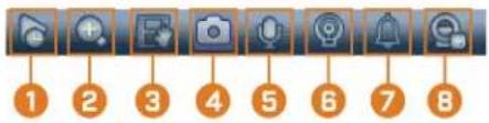
text_image
Row of eight numbered icons with corresponding labels, likely representing a sequence or checklist.- Instant Playback: Plays back recent video from the selected channel. By default, instant play-back is set to play the last 5 minutes of recorded video. See 16.4.15 Configuring Gener tem Settings, page 88 to set a custom playback length.
- Digital Zoom: Click to enable digital zoom. Click-and-drag over the camera image to zoo in on the selected area. Right-click to return to the full camera image. You can then re zoom in on a different area, or click the icon again to disable zoom.
- Real-time Backup: Click to start recording the current channel manually. Click again to s recording and save the video file to a USB flash drive (not included).
- Snapshot: Save a snapshot of the current camera image to a USB flash drive (not inclu
- Two-Way Audio: (Two—way audio cameras only) Click to enable two-way talk on compatible cameras.
- Warning Light: (Deterrence cameras only) Click to manually turn on the camera's warning light for 10 seconds.
- Siren: (Deterrence cameras only) Click to manually turn on the camera's siren for 10 seconds.
- Remote Device Search: Manage IP cameras over the network.
8.4 On-Screen Keyboards
The Full Keyboard is used to input alphanumeric characters, such as in user name or passv fields. The Number Keyboard is used to input numeric characters only, such as in the time date fields.
To use the Full Keyboard:
- Using the mouse, click on a field where alphanumeric characters are entered, such as the name and password fields.
• The Full Keyboard opens:

text_image
! ? @ # $ % = + * - _ ← 1 2 3 q w e r t y u i o p / a s d f g h j k l : Enter 4 5 6 z x c v b n m , . Shift 7 8 9 ← 0 &- Click Shift to switch between uppercase and lowercase characters.
• Right-click to close the Full Keyboard.
To use the Number Keyboard:
- Using the mouse, click on a field where numeric characters are entered, such as the date fields.
• The Number Keyboard opens:

- Right-click to close the Number Keyboard.
8.5 Camera Image Settings
Use the Camera Setting menu to adjust image settings for your cameras.
To adjust image settings:
- Right-click on the channel you would like to configure and select Camera Setting.

text_image
Camera Setting Channel 1 Config File Normal Image Brightness 50 Contrast 50 Saturation 50 Sharpness 50 Gamma 50 Mirror On Off Flip 0° Corridor Mode Enable Disable BLC Mode Off Exposure 3D NR On Off WB Mode Auto Day&Night Mode Auto Lorex Logo Enable Disable Default Refresh OK 3- Configure the following settings as needed:

NOTE
The settings listed below are only shown if they are supported on the selected camera. Some camera mo do not support all settings.
- Config File: Select from image setting presets.
• Brightness: Adjust the image brightness. - Contrast: Adjust the image contrast.
- Saturation: Adjust the vibrancy of colors in the image.
- Sharpness: Adjust the sharpness of the image.
• Gamma: Adjust the light-to-dark balance of the image. - Mirror: Select On to flip the image horizontally.
- Flip: Select 180^ to flip the image vertically, or select 0^ for the default orientation. You can also select 90^ or 270^ .
• Corridor Mode: Not supported.
• BLC Mode: Select one of the following backlight compensation modes:
• BLC (Back Light Compensation): Adjusts the lighting levels in the picture so you see objects in the foreground if there is a strong light source behind them.
WDR / HDR (Wide / High Dynamic Range): (Compatible camera required) The camera compensates for changes in brightness across the image to enhance the picture ity of both light and dark areas.
• HLC (High Light Compensation): The camera dims the brightest areas of the image to make them clearer.
- Off: Disable this function.
- Day&Night Mode: This setting sets the camera's day/night mode. Select Auto for the camera to automatically determine whether to use color or black and white mode. Select Black&White for the camera to use black and white mode at all times. Select Color for the camera to use color mode at all times.

NOTE
It is recommended for most installations to select Auto mode. Using Color mode will keep the camera in color even as light levels drop, which will impact image quality on cameras without low-light image sensors.
- 3D NR: Select On to turn on the camera's noise reduction feature. Noise reduction will ensure a cleaner image, especially at night, and may reduce the amount of disk space to store video.
- WB Mode: This mode allows you to adjust white balance levels for the camera. Choc from the list of preset modes, or select Auto to have the system automatically set the mal white balance mode.
-
Lorex Logo: Select Enable to include a Lorex watermark on the camera image.
-
Click OK to save changes.

NOTE
You must save changes to apply settings changes. It is recommended to adjust one setting at a time so see the results of each change. Click Default to reset the camera to default image settings.
Recording9
By default, the system is set to immediately record video from connected cameras continuous 24 hours a day. You can customize the recording settings according to your needs.
9.1 Video Recording Types
The system supports the following recording types:
- Continuous recording: Normal, continuous recording. A icon is shown in the bottom left-hand corner of the camera image when continuous recording is in progress.
- Motion recording: Motion-triggered video recording. An icon is shown in the bottom left-hand corner of the camera image when a motion event is being recorded.
- Smart motion recording: Smart motion video recording of a person or vehicle. As shown in the bottom left-hand corner of the camera image when a motion event of a p vehicle is being recorded. For more details on configuring smart motion detection of peop and/or vehicles, see 14 Smart Motion Detection, page 48.
9.2 Configuring Recording Quality
The system uses two video recording streams: a Main Stream and a Sub Stream. The Main Stream records high quality video to your system's hard drive. The Sub Stream records low lution video for efficient streaming to devices over the Internet. You can customize the vide ity settings for these streams according to your needs.
To configure recording quality:
-
From the Live View display, right-click to open the Quick Menu, then click Main Menu
-
Click 🙏, then click RECORDING. Click the Recording tab on the top panel.

text_image
RECORDING Recording Snapshot Overlay Channel 1 Type Continuous Sub Stream1 Compression H.265 H.264H Super H.264/6 Off Resolution (4K)3840x218 (D1)704x480 Frame Rate(FPS) 15 15 Bit Rate Type CBR CBR Bit Rate(Kbps) 4096 256 Reference Bit Rate 1024-4096Kbps 258-1280Kbps Audio/Video ✓ ✓ ✓ Audio Encode G.711A AAC Sampling Rate 8000 8000 Default Copy Refresh OK Cancel Apply RECORDING- Under Channel, select the camera you would like to configure.
-
Under Type, select the recording type you want to configure the recording quality settings for.
-
Configure the following settings. Except where noted, options for Main Stream and Sub Stream are the same:
-
Compression: Select the video compression type that will be used. For H.265 compatible cameras, it is recommended to select H.265, as it will use the least amount of disk
- Super H.264/5: (Main Stream only) Enable to reduce system requirements for unimportant recordings to maximize hard drive storage. If you enable, select the Quality from 1 (lowest) to 6 (highest).
- Resolution: Select the resolution that you want to use to record the selected channel. er resolutions create a more detailed image, but take up more hard drive space to re and require more bandwidth to stream to connected computers or mobile devices.

NOTE
Available resolutions for the Main Stream and Sub Stream depend on the model of camera that is connected to the system.
- Frame Rate (FPS): Select the frame rate in Frames Per Second (FPS) that each strear record at. A higher frame rate provides a smoother picture, but requires more storage bandwidth.
- Bit Rate Type: Select CBR (Constant Bit Rate) or VBR (Variable Bit Rate) to determine the bit rate type. If you select VBR, select the Quality from 1 (lowest) to 6 (highest).
- Bit Rate (Kbps): Select the bit rate for each recording stream. A higher bit rate results in a better image, but increases the amount of hard drive space or bandwidth required.

NOTE
Recording settings include options for audio recording. For full details, see 20 Connecting Audio Devices, page 104.
- Click Apply.
- (OPTIONAL) Click Copy to apply the settings for the current channel to one or more other channels.
9.3 Setting the Recording Schedule
You can set a custom recording schedule according to your needs. For example, you can set system to record continuously during business hours and record on motion detection only out of business hours.
A custom recording schedule helps reduce the amount of hard drive space required, increasing time your system can retain recordings.
To configure the recording schedule:
-
From the Live View display, right-click to open the Quick Menu, then click Main Menu
-
Click X, then click STORAGE. Click the SCHEDULE tab on the side panel.

text_image
SCHEDULE HDD MAN 78 RECORD Record Channel 1 Pre-record 4 s ANR 1800 s Continuous Motion Smart Motion All 0 2 4 6 8 10 12 14 16 18 20 22 24 Sun Mon Tue Wed Thu Fri Sat Default Copy OK Cancel Apply 5 STORAGE-
Under Channel, select the channel you would like to configure or select All.
-
Configure the schedule as needed:
-
Check Continuous, Motion, or Smart Motion to select the recording type you would like to configure.
- Click-and-drag on each day to customize the recording schedule. The schedule is set up a grid, which each block representing one hour.
-
Click beside 2 or more days to link schedules (). This allows you to quickly change multiple schedules at once.
• To make fine adjustments to a schedule, click This will allow you to set exact start and end times for a schedule.
• To disable all recording of the selected type on the selected way, click -
Click Apply.
9.4 Setting up Scheduled or Manual Recording
You can set the system to record based on a schedule or you can manually turn recording off. By default, the system is set to always record on a schedule.
To configure the recording schedule, see 9.3 Setting the Recording Schedule, page 24.
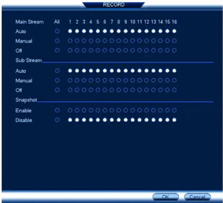
To set options for manual recording:
- From the Live View display, right-click to open the Quick Menu. Click Manual, then Record.
-
Under Main Stream, select how the system will record the Main Stream for each channel
-
Auto: Main Stream recording will follow the recording schedule.
- Manual: The system will record the Main Stream continuously as long as this option checked.
-
Off: The system will not record the Main Stream for this channel. This option is not recommended.
-
Under Sub Stream, select how the system will record the Sub Stream for each channel.
-
Auto: Sub Stream recording will follow the recording schedule.
- Manual: The system will record the Sub Stream continuously as long as this option i checked.
-
Off: The system will not record the Sub Stream for this channel. This option is not recommended.
-
Under Snapshot, select Enable to enable snapshot recording on each channel. Or, select Disable to disable snapshot recording.

NOTE
To set more preferences for snapshots recording, see 16.2.4 Configuring Snapshot Recording Settings, page 62.
- Click Apply.
9.5 Configuring Hard Drive Overwrite
When the hard drive is full, the system will overwrite the oldest recordings by default. This is commended, as it makes sure that your system will continue to record without any input from You can also set the system to stop recording once the hard drive is full.
To configure hard drive overwrite:
-
From the Live View display, right-click to open the Quick Menu, then click Main Menu
-
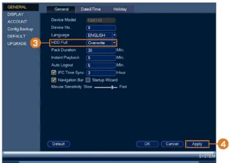
Click X, then click SYSTEM. Click the GENERAL tab on the side panel, then click the General tab on the top panel.
text_image
GENERAL DISPLAY ACCOUNT Config Backup DEFAULT UPGRADE 3 General Date&Time Holiday Device Model N841A8 Device No. 8 Language ENGLISH HDD Full Overwrite Pack Duration 30 Min. Instant Playback 5 Min. Auto Logout 5 Min. IPC Time Sync 3 Hour Navigation Bar Startup Wizard Mouse Sensitivity Slow Fast Default OK Cancel Apply SYSTEM- Ensure HDD Full is set to Overwrite to overwrite the oldest recordings when the hard drive is full.
| NOTE |
| Select Stop Record for the system to stop recording when the hard drive is full. |
- Click Apply.
Playback
Search through and playback recorded video files on the system.
10.1 Playing Back Video from the Hard Drive
To play back recorded video:
- From the Live View display, right-click to open the Quick Menu, then click Playback.
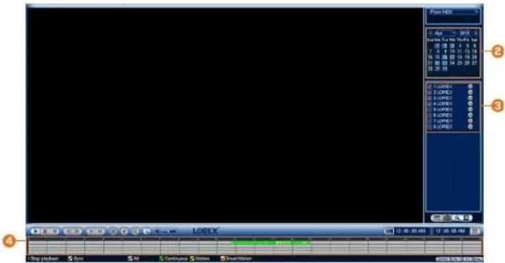
text_image
Play HSB 1 - Max - 2018 BackUp Tools Tools Set 17:00:4:5:6 7:00:10:13:18 4:00:15:25:35:35 21:00:24:25:29:27 23:29:33 2 LOPEX 2 LOPEX 2 LOPEX 2 LOPEX 2 LOPEX 2 LOPEX 2 LOPEX 2 LOPEX 2 LOPEX 2 LOPEX 2 LOPEX 2 LOPEX 2 LOPEX 2 LOPEX 2 LOPEX 2 LOPEX 2 LOPEX 2 LOPEX 2 LOPEX 2 LOPEX 2 LOPEY 2 LOPEY 2 LOPEY 2 LOPEY 2 LOPEY 2 LOPEY 2 LOPEY 2 LOPEY 2 LOPEY 2 LOPEY 2 LOPEY 2 LOPEY 2 LOPEY 2 LOPEY 2 LOPEY 2 LOPEY 2 LOPEY 2 LOPEY 2 LOPEY 2 LOPEY 2 LOPEE 2 LOPEE 2 LOPEE 2 LOPEE 2 LOPEE 2 LOPEE 2 LOPEE 2 LOPEE 2 LOPEE 2 LOPEE 2 LOPEE 2 LOPEE 2 LOPEE 2 LOPEE 2 LOPEE 2 LOPEE 2 LOPEE 2 LOPEE 2 LOPEE 2 LOPEE 2 LOPEe 2 Lopee 2 Lopee 2 Lopee 2 Lopee 2 Lopee 2 Lopee 2 Lopee 2 Lopee 2 Lopee 2 Lopee 2 Lopee-
Use the calendar on the right to select the day to playback.
-
Check the channels you want to play back. Click the icons to the right of each channel to choose the video quality for Main Stream, for Sub Stream).
-
Click inside the video bar to select the playback time. The system will begin playing back from the selected time.
10.2 Playback Controls
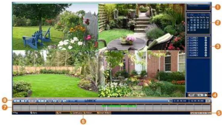
text_image
Screenshot of a garden editing software interface with labeled panels and toolbars-
Select Playback Device: Choose between searching the recorder's hard drive or a USB flash drive (not included).
-
Calendar: Select the date to playback.
-
Channel Selection: Select channels and video quality for playback.
-
Viewing Modes:
• Not supported
• Not supported
- Bookmark List: Shows all bookmarked recordings for a single channel on the selected date (requires bookmarked recordings — see below for details).
-
File List: Shows all available recordings for the selected date and channel(s) in format.
-
Playback Bar Time Scale: Select the length of the time period shown on the playback b
- Recording Type Filters: Click to show/hide recording types.
- Playback Bar: Click inside the bar to select a playback time.
8. Playback Controls:
• /Play / Pause
- Stop
• Play Backwards
- Previous Frame: Go to the previous frame when video is paused.
• Next Frame: Go to the next frame when video is paused.
- Slow Playback: Click repeatedly to slow the video down by half speed up to 16 slower than normal. Click again to return to regular speed.
- Fast Playback: Click repeatedly to double the speed of the video up to 16 × faste normal. Click again to return to regular speed.
- Area Search: Click to select an area of the camera image and play back all readings with motion in the selected area. For full details, see 10.3 Area Search, page 30.
- Add Bookmark: Bookmark recordings for easy retrieval.
- Digital Zoom: Click to enable digital zoom. Click-and-drag over the camera image zoom in on the selected area. Right-click to return to the full camera image. You can repeat to zoom in on a different area, or click the icon again to disable zoom.
• Show/Hide Smart Search Rules: Click to show/hide active areas for smart detection of people and vehicles during playback.
• Volume / Mute: Click on the volume bar to set the volume for audio i playback. Click the icon to mute/unmute.

NOTE
You must be viewing an audio camera in single channel to hear audio. You must also be using a HDMI monitor with built-in speakers, or connect an external speaker to the recorder in order to be audio.
- Audio recording and / or use of listen-in audio without consent is illegal in certain jurisdictions. Corporation assumes no liability for use of its products that does not conform with local laws.
Video Clip: Back up a custom video clip to a USB flash drive (not included). For full instructions, see 10.4 Video Clip Backup, page 32.
10.3 Area Search
Play back all recordings from a single channel with motion in a specific area of the camer
To perform an area search:
- From the Live View display, right-click to open the Quick Menu, then click Playback.
text_image
Play HSB 2015 Start My To Kit The File Set 10:00:00 7:5:00 2 0 9 10 11 12 13 4 10 11 12 13 14 15 5 16 17 18 19 20 6 21 22 23 24 25 26 7 27 28 LODEX LODEX LODEX LODEX LODEX LODEX LODEX LODEX LODEX LODEX LODEX LODEX LODEX LODEX LODEX LODEX LODEX LODEX LODEX LODEX LODEX LODEX LODEX LODEX LODEX LODEY LODEY LODEY LODEY LODEY LODEY LODEY LODEY LODEY LODEY LODEY LODEY LODEY LODEY LODEY LODEY LODEY LODEY LODEY LODEY LODEY LODEY LODEY LODEY LODEY LODE Y LODE Y LODE Y LODE Y LODE Y LODE Y LODE Y LODE Y LODE Y LODE Y LODE Y LODE Y LODE Y LODE Y LODE Y LODE Y LODE Y LODE Y LODE Y LODE Y LODE Y LODE Y LODE Y LODE Y LODE Y LODEY-
Use the calendar on the right to select the day to playback.
-
Check a single channel you want to play back. Click the icon to the right of the channel to choose the video quality for Main Stream, for Sub Stream).
-
Click inside the video bar to select the playback time. The system will begin playing back from the selected time.
-
Click to configure an area for the search.
-
The icon changes to , and the camera image appears with a grid overlay. Click or click and-drag to add / remove squares from the grid. Solid blue areas mark the part of the that will be searched for motion events.

text_image
Syst-130 2013.10 Syst-Mo Tu We The Fri Sat 7 8 9 10 11 12 13 14 15 16 17 18 19 20 21 22 23 24 25 26 27 28 29 30 1 LOREX 2 LOREX 3 LOREX 4 LOREX 5 LOREX 6 LOREX 7 LOREX 8 LOREX LOREX 10:09:29 AM - 10:09:30 AM Play Sync All Continuous Motion Smart Motion- Click to begin area search.
10.4 Video Clip Backup
Video clip backup allows you to select a duration of video during playback mode and save USB device (not included).
To use video clip backup:
- Connect the USB thumb drive (not included) to a free USB port on the recorder.
- From the Live View display, right-click to open the Quick Menu, then click Playback.

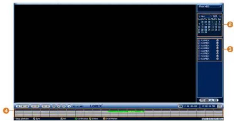
text_image
File HX Age - 2019 Playable in the Play Date 00:28:24:5:6 7:00:00:11:12:19 14:00:00:12:19:20 21:00:00:22:26:27 28:26:35 LOREX LOREX LOREX LOREX LOREX LOREX LOREX LOREX LOREX LOREX LOREX LOREX LOREX LOREX LOREX LOREX LOREX LOREX LOREX LOREX LOREX LOREX LOREX LOREX LOREX LOREx LOREx LOREx LOREx LOREx LOREx LOREx LOREx LOREx LOREx LOREx LOREx LOREx LOREx LOREx LOREx LOREx LOREx LOREx LOREx LOREx LOREx LOREx LOREx LOREx LOR Ex LOR Ex LOR Ex LOR Ex LOR Ex LOR Ex LOR Ex LOR Ex LOR Ex LOR Ex LOR Ex LOR Ex LOR Ex LOR Ex LOR Ex LOR Ex LOR Ex LOR Ex LOR Ex LOR Ex LOR Ex LOR Ex LOR Ex LOR Ex LOR Ex LOR EX LOR Ex LOR Ex LOR Ex LOR Ex LOR Ex LOR Ex LOR Ex LOR Ex LOR Ex LOR Ex LOR Ex LOR Ex- Use the calendar on the right to select the day to playback.
- Check the channels you want to play back. Click the icons to the right of each channel to choose the video quality for Main Stream, for Sub Stream).
- Click inside the video bar to select the playback time. The system will begin playing base from the selected time.

text_image
LOREX Play Sync All Continuous Motion Smart Motor-
Click to mark the beginning of the video clip, then click again to mark the end of the video clip.
-
Click to open the backup menu.

text_image
Backup File Format DAV ASF AVI MP4 1 Name(Type) Free Space/Total Space Device Status 1 sdb1(USB DISK) 7.47 GB/7.49 GB Ready 1 CH Type Start Time End Time Size(MB) 1 M 04-02-19 10:09:25AM 04-02-19 10:09:30AM 50% Page Up Page Down Select/Cancel backup device or file Combine Video Space Required / Space Remaining:2.22 MB/7.47 GB BackUp-
Select a filetype for your backup file.
-
Click Backup.
10.5 Playing Back Video from a USB Drive
If you have video files saved to a USB flash drive (not included), you can play them back the system.
For full instructions on backing up video to a USB flash drive, see 11 Backup, page 35.
To play back video from a USB flash drive:
-
Connect the USB thumb drive (not included) with video files on it into a free USB po recorder.
-
From the Live View display, right-click to open the Quick Menu, then click Playback.

text_image
From:100 + 4pt - 23/18 Start: 5.1.16 15:30:50 7 E B 11 12 13 14 15 16 17 18 19 20 21 22 23 24 25 26 27 28 29 30 LOREX LOREX LOREX LOREX LOREX LOREX LOREX LOREX LOREX LOREX LOREX LOREX LOREX LOREX LOREX LOREX LOREX LOREX LOREX LOREX LOREX LOREX LOREX LOREX LOREX LOREx Log x Log y Log z Log w Log x Log y Log z Log w Log y Log z Log w Log y Log z Log w Log y Log z Log w Log y Log z Log w Log y Log z Log w Log y Log z Log w Log y Log z Log w Log y Log z Log w Log y Log z Log w Log y Log z Log w Log y Log z Log w- Click the dropdown and select From IO Device.
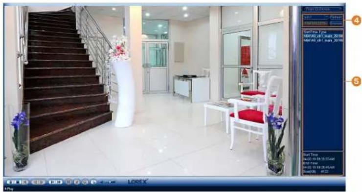
natural_image
Interior view of a modern hotel lobby with staircase, white furniture, and glass doors (no visible text or symbols)- Click Browse to locate the video file on your USB flash drive.
- Double-click the video file you want to open from the file list to start playback.
Backup
Backup video files to external USB flash drive (not included).
11.1 Formatting the USB Flash Drive
It is recommended to format your USB thumb drive (not included) before using it with the
| CAUTION |
| Formatting the USB device will permanently erase all data. This step cannot be undone. |
Prerequisite:
- Connect a USB flash drive (not included) to a free USB port on the unit.
To format a USB flash drive:
-
From the Live View display, right-click to open the Quick Menu, then click Main Menu
-
Click , then click BACKUP.
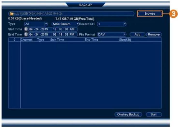
text_image
BACKUP sdb1(USB DISK)NB41A8/2019-4-24 Browse 0.00 KB(Space Needed) 7.47 GB/7.49 GB(Free/Total) Type All Main Stream Record CH 1 Start Time 04 - 24 - 2019 12 : 00 : 00 AM End Time 04 - 24 - 2019 03 : 11 : 08 PM File Format DAV Add Remove 0 Channel Type Start Time End Time Size(KB) Onekey Backup Start- Click Browse to locate the USB drive you want to format.
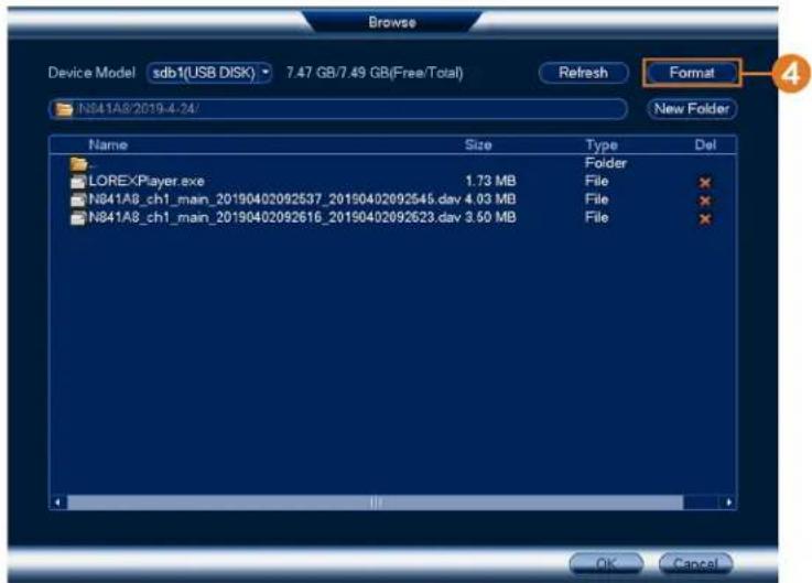
text_image
Browse Device Model:sdb1(USB DISK) 7.47 GB/7.49 GB(Free/Total) Refresh Format N841A8'2019-4-24/ New Folder Name Size Type Del LOREXPlayer.exe 1.73 MB Folder N841A8_ch1_main_20190402092537_20190402092545.dav 4.03 MB File N841A8_ch1_main_20190402092616_20190402092623.dav 3.60 MB File OK Cancel-
Select the correct drive, then click Format.
-
Select a format mode:
• FAT32: Recommended — offers the greatest compatibility with other devices.
- NTFS: Advanced users only — should only be used on drives larger than 32GB when sizes will be larger than 4GB.
- Click OK.
11.2 Backing Up Video
You can save video recordings from your system to a USB flash drive. Ensure you format drives before backing up video (see 11.1 Formatting the USB Flash Drive, page 35 for deta
To back up video:
- From the Live View display, right-click to open the Quick Menu, then click Main Menu
2. Click

BACKUP.

text_image
3 27.92 GB(Space Needed) 7.41 GB/7.49 GB(Free Total) Browse Type All Main Stream Record CH 1 Start Time 04 - 02 - 2019 12 : 00 : 00 AM End Time 04 - 02 - 2019 03 : 11 : 08 PM File Format DAV Add Remove 543 Channel Type Start Time End Time Size(MB) 1 1 M 04-02-19 12:00:00AM 04-02-19 12:00:33AM 18304 2 1 C 04-02-19 12:00:33AM 04-02-19 12:00:35AM 3456 3 1 M 04-02-19 12:00:35AM 04-02-19 12:05:28AM 161936 4 1 C 04-02-19 12:05:28AM 04-02-19 12:05:40AM 8576 5 1 M 04-02-19 12:05:40AM 04-02-19 12:06:50AM 37760 6 1 C 04-02-19 12:06:50AM 04-02-19 12:07:11AM 13184 7 1 M 04-02-19 12:07:11AM 04-02-19 12:07:53AM 23424 8 1 C 04-02-19 12:07:53AM 04-02-19 12:08:30AM 20864 9 1 M 04-02-19 12:08:30AM 04-02-19 12:09:20AM 28032 10 1 C 04-02-19 12:09:20AM 04-02-19 12:09:32AM 8576 11 1 M 04-02-19 12:09:32AM 04-02-19 12:11:46AM 70016 12 1 C 04-02-19 12:11:46AM 04-02-19 12:13:11AM 45568 13 1 M 04-02-19 12:13:11AM 04-02-19 12:13:52AM 23552 14 1 C 04-02-19 12:13:52AM 04-02-19 12:15:10AM 41856 15 1 M 04-02-19 12:15:10AM 04-02-19 12:16:12AM 33664 16 1 C 04-02-19 12:16:12AM 04-02-19 12:16:16AM 1744 17 1 C 04-02-19 12:16:12AM 04-02-19 12:16:16AM 4480 Onekey Backup Start-
Click Browse to select the USB backup device and the folder to save your backup files
-
Configure the following:
-
Type: Select the recording type you would like to search for or select All to search all recording types.
- Record CII: Select the channel you would like to search or select All to search all channels.
- Start Time / End Time: Select the start and end time for your search.
-
File Format: Select DAV to save files to save files to .dav format. You can playback .dav files using the Lorex video player software.
-
Click Add. A list of files that match your search criteria appears.
-
Check files you would like to backup.
-
Click Start

NOTE
HD video files saved on the system may take up a large amount of disk space. The size of video file and the amount of free space on your USB device is shown on screen.
11.3 Using Video Clip Backup
Video clip backup allows you to select a duration of video during playback mode and save USB device (not included). For full instructions on video clip backup, see 10.4 Video Clip Backup, page 32.
11.4 Viewing Backed Up Files
Use the free Lorex Player to play back .dav files.
11.4.1 Viewing Backed Up Files on PC
-
Download and install the Lorex Player for PC from the recorder's product page at lorex.com
-
Double-click one of the files under the Group File List on the left to begin playback.
| NOTE |
| By default, the video file will play in the top-left playback window as shown below. Select a back window then double-click another file to play additional videos at the same time. |
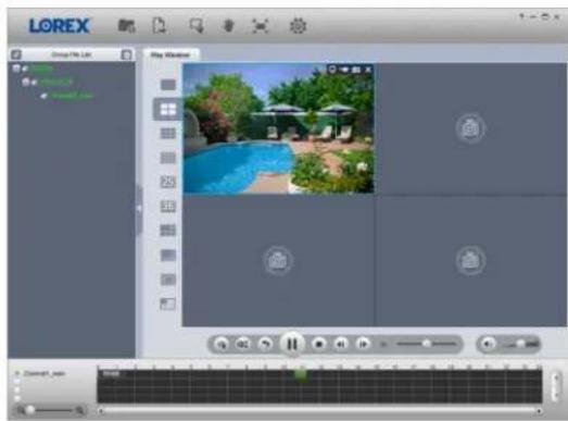
natural_image
Screenshot of a video editing software interface showing a pool scene with greenery and blue umbrellas, displayed within a media player window (no readable text or symbols on the main image area)OR
Click to open a backed up video file in another location.
- Use the Lorex Player controls to control playback or select other files for playback.

NOTE
For a full overview of Lorex Player controls, see 11.4.3 Lorex Player Controls, page 39.
11.4.2 Viewing Backed Up Files on Mac
- Download and install the Lorex Player for Mac from the recorder's product page at lorex.com
- Double-click the downloaded file in Safari to extract the Lorex Player app file.
-
Drag the Lorex Player app to your Desktop or Applications list. Double-click Lorex Player to open the application.
-
Double-click one of the files under the Group File List on the left to begin playback.
| NOTE |
| By default, the video file will play in the top-left playback window as shown below. Select a back window then double-click another file to play additional videos at the same time. |

text_image
LOREX Crop File List Play Window 100% 200% 300% 400% 500% 600% 700% 800% 900% 1000%OR
Click to open a backed up video file in another location.
- Use the Lorex Player controls to control playback or select other files for playback.

NOTE
For a full overview of Lorex Player controls, see 11.4.3 Lorex Player Controls, page 39.
11.4.3 Lorex Player Controls

text_image
LOREX Group File List Play Window 1 2 3 4 5 6 7 8 9 10 11 12 Channel_max- File List: Double-click to open a file.
- Viewing Mode: Select between single-channel viewing and various split-screen options.
3. Hide/Show File List
4. Playback Controls:
• : Playback files in sequence.
• Synchronize playback times.
• : Play/pause playback.
- □: Stop playback.
• : Previous frame.
• ▶: Next frame.
• 1X : Playback speed.
• : Volume control.
5. Zoom Timeline
- Display Area: Double-click a video file to expand. Click the controls inside the display area to do the following:
• View information about the video file.
• Start/stop a manual recording of the video file.
• Take a snapshot of the video file.
- ✗: Close the video file.
- Add Files: Click to open backed up video files.
- Export Files: Export a video file to a different format.
- Digital Zoom: Click, then click-and-drag over a camera image to zoom in. Right-click to turn to the full image.
- Drag: Click, then click-and-drag to move around a camera image that has been digitally zoomed in.
-
Fullscreen: Click to open the player in full screen. Press ESC to exit full screen.
-
Settings: Click to open the configuration menu for the player. From here you can control the default file formats and save locations for snapshots and control the aspect ratio.

text_image
LOREX Play Options Event No. 4 Config Snap Path Browse Video Path Browse Snap Format SNP RecordFormat DATA Video Proportion 10.0 Signal Channel Audio Channel Language(Select Record) Vertical SyncrimationMotion Detection12
Configure motion detection settings to ensure that events are captured according to your preferences.
12.1 Status Icons
The system displays different icons in the bottom left-hand corner of the camera image to you of motion detection events:
- Motion detection: Motion has been detected by the camera. Ron is shown in the bottom left-hand corner of the camera image to show that motion was detected, but the sys not recording a motion event. This is because motion recording is not enabled on the ch or the movement detected by the camera was not significant enough to trigger motion reing. See 12.2 Configuring Motion Detection, page 42 to configure settings for motion dete and recording.
- Motion recording: Motion-triggered video recording. An icon is shown in the bottom left-hand corner of the camera image when a motion event is being recorded.
12.2 Configuring Motion Detection
Set preferences for motion detection per channel.
To configure motion detection:
-
From the Live View display, right-click to open the Quick Menu, then click Main Menu
-
Click X, then click EVENT.
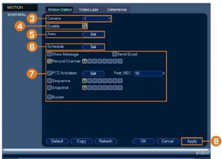
text_image
MOTION WARNING Camera Enable Area Set Schedule Show Message Record Channel PTZ Activation Sequence Snapshot Buzzer Default Copy Refresh OK Cancel Apply Event- Select a channel to configure motion detection for.
-
Check to enable motion detection on the selected channel.
-
Click Setup next to Area to configure which areas of the image will be enabled for motion detection. A grid will appear on the monitor:

text_image
Name Region1 Sensitivity 60 Threshold 5- The camera image appears with a red grid overlay. This means the entire image is set for motion detection.
- Click or click-and-drag to add / remove boxes from the active area. Cells that have moved from the active area appear green.
-
Hover near the top of the image to reveal zone selection. You can set up to 3 diff with different sensitivity and threshold values.
• Right-click when finished. -
Click Setup next to Schedule to choose which days and times of the week to enable motion detection:

text_image
Set All 0 2 4 6 8 10 12 14 16 18 20 22 24 Sun Mon Tue Wed Thu Fri Sat Set Set Set Set Set Set Set Set OK Cancel- Click or click-and-drag along each of the yellow timelines to quickly add or remove from each day's schedule in 15-minute segments.
- Click beside 2 or more days to link schedules (). This allows you to quickly change multiple schedules at once.
-
To make fine adjustments to a schedule, click Set. This will allow you to set exact end times for a schedule.
-
Choose how the system will react when motion is detected:
-
Show Message: Check to enable an on-screen pop-up when one of your cameras detect motion. On-screen pop-up shows the channels an event occurred on and the type of c
- Send Email: Check to enable email alerts. You must configure email alerts before you be able to receive them (see 16.4.4 Configuring Email Alerts, page 77).
- Record Channel: Select the channels that will record when motion is detected on the elected channel. Set the length of recording following a video loss event in the Post_I field.
- PTZ Activation: Set connected PTZ cameras to start a tour, pattern, or go to a prese location.
- Sequence: Sequence mode will begin. Select the numbered tiles next to this option to clude the corresponding channels in the sequence.
- Snapshot: Select the numbered tiles next to this option to save a snapshot of the corresponding channels.
-
Buzzer: Check to enable the system buzzer.
-
Click Apply.
Active Deterrence13
Lorex Active Deterrence cameras feature bright, customizable warning lights and a remote-triggered siren. The recorder allows you to customize automatic light-triggering when motion is tested to deter intruders (see 13.1 Automatic Deterrence Settings, page 45). You can also trigger the lights and sirens manually using the recorder or Lorex Home connectivity software (see Manually Activate Deterrence Features, page 47).
For a complete list of compatible deterrence cameras, navigate to your recorder series at lorex.com/compatibility.
natural_image
Exterior view of a modern security camera (no visible text or symbols on body)13.1 Automatic Deterrence Settings
Set preferences for automatic warning light triggering on compatible Lorex deterrence cameras.
To configure deterrence settings:
- From the Live View display, right-click to open the Quick Menu, then click Main Menu
- Click ALARM. Click the MOTION tab on the side panel, then Deterrence on the top panel.

text_image
MOTION WARNING 3 Camera 3 Enable Area Set Schedule Set Duration 10 Warning Light ○ Strobe Strobe Frequency Low Sensitivity 60 Threshold 5 Refresh OK Cancel Apply 9 EVENT- Select the channel of a connected deterrence camera.
- Check Enable.

NOTE
This is for automatic warning light triggering only. You can manually activate the warning light without enabling automatic warning light triggering.
and sire
- Click Set next to Area to set an active area for automatic deterrence.

natural_image
Green outdoor patio area with table, chairs, and fence, set against a backdrop of trees and a distant house (no text or symbols visible)- The camera image appears with a grid overlay. The green area is the active area for deterrence.
- Click or click-and-drag to add / remove boxes from the active area.
-
In the example image above, only motion around the garage or on the porch will trigger warning light.
• Right-click when finished. -
Click Set next to Schedule to set the weekly schedule for automatic deterrence.
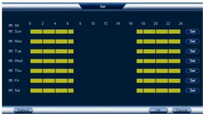
text_image
Set All Sun Mon Tue Wed Thu Fri Sat 0 2 4 6 8 10 12 14 16 18 20 22 24 Set Set Set Set Set Set Set Set OK Cancel- Click or click-and-drag along each of the yellow timelines to quickly add or remove from each day's schedule in 15-minute segments.
- Click beside 2 or more days to link schedules (). This allows you to quickly change multiple schedules at once.
- To make fine adjustments to a schedule, click Set. This will allow you to set exact end times for a schedule.
-
Click OK when finished.
-
Configure preferences for the warning light:
• Duration: Choose how long the warning light will stay on when motion is detected.
- Select Warning Light for a solid white light, or Strobe for a flashing light. If you select Strobe, set how quickly the light will flash under Strobe Frequency.
-
Set the sensitivity and threshold for the warning light:
-
Sensitivity: The amount of activity required to classify an on-screen event as motion. A higher sensitivity will classify even small movements as motion events, and trigger the warning light.
-
Threshold: The level at which a motion detection event triggers the warning light. A threshold will trigger the warning light even for small objects.
-
Click Apply.
13.2 Manually Activate Deterrence Features
The system has multiple options for activating deterrence features.
To activate deterrence features on a single camera:
- Hover the mouse pointer near the top of the camera image in Live View to reveal the Toolbar. Click to activate the warning light or to activate the siren.

- Activate deterrence features using the Lorex Home app. For details, see 17 Connecting Remotely using the Lorex Home Mobile App, page 97.
To activate deterrence features on all connected cameras:
- Push and hold the front panel panic button on the recorder for 3 seconds.
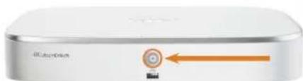
natural_image
Close-up of a silver electronic device with a circular button and orange arrow pointing to it (no visible text or symbols)- From the Live View display, check on the Navigation Bar.

Smart Motion Detection14
The system supports detection of people and vehicles with compatible IP cameras only. This deliver more relevant notifications when using the Lorex Home app for remote viewing. You also link white light deterrence to person and/or vehicle detection on compatible Lorex deter cameras for an added level of smart security.
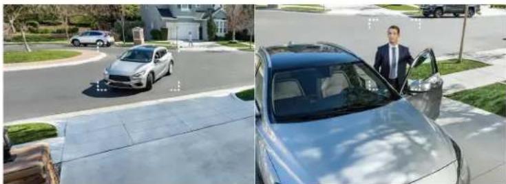
natural_image
Split image showing a silver car on a residential street and a man in a suit standing beside the car's door (no visible text or symbols)14.1 Ensuring Accurate Person & Vehicle Detection
The following are important camera installation notes to ensure accurate Person & Vehicle dtion. Refer to the documentation that came with your camera or search for your camera mo number at lorex.com for full mounting instructions.
- Choose a location where objects of interest will be no further than 50ft (\~15m) from the camera.
- Angle the camera so that objects of interest appear in the bottom 13 of the camera imag

natural_image
Exterior view of a residential area with cars and pedestrians, overlaid with a green heatmap-style overlay (no readable text or symbols)- Angle the camera between 30\~60° down from the level position.
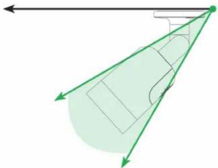
natural_image
Diagram showing a vehicle with a curved trajectory and green directional arrows, no text or symbols present.• Install the camera between 8-16ft (2.5-5m) off of the ground.
| NOTE |
| Accuracy of Person & Vehicle detection will be influenced by multiple factors, such as the object's the camera, the size of the object, and the height and angle of the camera. Night vision will also racy of detection. |
14.2 Configuring Person & Vehicle Detection
Set preferences for person and/or vehicle detection per channel.
| NOTE |
| This chapter covers motion detection settings only. See the references below for full instructions on menus shown below: |
To configure person and/or vehicle detection:
-
From the Live View display, right-click to open the Quick Menu, then click Main Menu
-
Click 📄, then click EVENT. Click the MOTION tab on the side panel, then click Deterrence on the top panel.
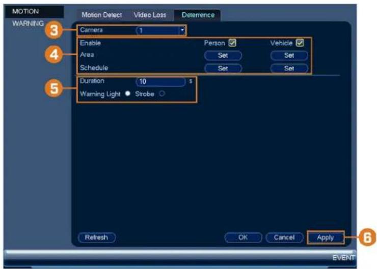
text_image
MOTION WARNING 3 Camera 1 Enable Person Vehicle Area Set Set Schedule Set Set Duration 10 Warning Light • Strobe Refresh OK Cancel Apply 6 EVENT-
Select a channel with a compatible camera you would like to configure smart detection 1
-
Configure the following:
- Enable: Check Person or Vehicle or both to enable each type of smart detection. - Area: Click Set under each detection type you have enabled to set the active area for detection.
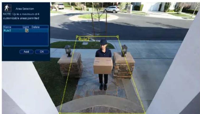
text_image
Area Selection NOTE: Up to a maximum of 4 customizable areas permitted Name Light Delete Rule2 Add OK Rule2- Click Add to set an area for person or vehicle detection on the selected channel. And-drag the corners to resize the area.
- For most accurate results, set an area where objects of interest will move within the bounding box as well as into / out of.
- Check Light next to a rule to flash the camera's warning light when an object is detected.
- See 14.1 Ensuring Accurate Person & Vehicle Detection, page 48 for optimal camera positioning for person and vehicle detection.
- Schedule: Click Set under each detection type you have enabled to set the weekly schedule for detection.
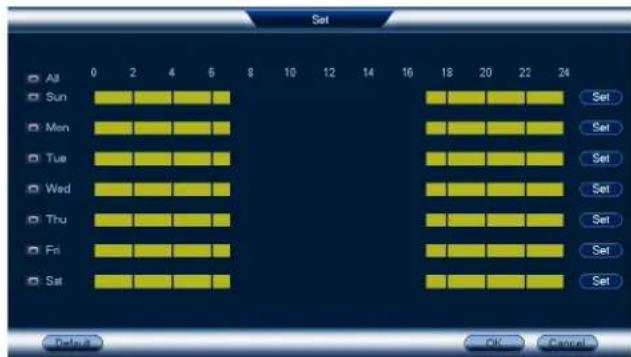
text_image
Set All 0 2 4 6 8 10 12 14 16 18 20 22 24 Sun Mon Tue Wed Thu Fri Sat Set Set Set Set Set Set Set OK Cancel- If you choose to flash the camera's warning light when a person or vehicle is detected, are the following warning light options:
- Duration: Enter the time in seconds the warning light will remain on after a person hicle is detected.
- Warning Light / Strobe: Choose Warning Light to use a solid white light, or Strobe for a flashing light. If you select Strobe, choose the Strobe Frequency to determine how quickly the warning light will flash when triggered.
- Click Apply.
14.3 Searching for Person & Vehicle Detection Events (Smart Search)
Smart Search lets you filter recorded video to search for person detection events, vehicle detect events, or both.
| NOTE |
| In order to use Smart Search, you must configure at least one channel's smart detection settings. S above for full instructions. |
To perform a Smart Search:
- From the Live View display, right-click to open the Quick Menu, then click Smart Sear

text_image
Smart Search Channel All Start Time 05 - 08 - 2019 12 : 00 : 00 AM End Time 05 - 09 - 2019 11 : 59 : 59 PM Event Type All Smart Search- Select a channel to search for detection events from, or select All.
- Enter a start and end time for your search.
- Next to Event Type, select Person, Vehicle, or All.
- Click Smart Search.

text_image
Smart Check 6 1:1 SetTo 1- Events that match your search criteria are displayed. You now have the following options
- Click a thumbnail to preview the event. Double-click the preview window to view in screen.
- Check thumbnails to perform other actions:
。: Back up events.
。 E: Lock events.
。: Bookmark events.
Managing Passwords and User Accounts
Passwords are enabled by default and are required to access the Main Menu or connect to tem using a computer or mobile device. You will be prompted to create a custom password you connect for the first time.
| NOTE |
| If you forget the password to the system, contact technical support to have it reset. |
15.1 User Accounts
The system includes the following default accounts:
- admin: The administrator account has full access to the system, may configure all system tings, and can manage user accounts.
- user: User accounts are secondary accounts which can be assigned limited access to system settings and camera feeds.
15.1.1 Changing Passwords
You can change the system password of the administrator and user accounts.
To change an account password:
-
From the Live View display, right-click to open the Quick Menu, then click Main Menu
-
Click 📄, then click SYSTEM. Click the ACCOUNT tab on the side panel, then click User on the top panel.
-
Click next to the account you want to change the password for.
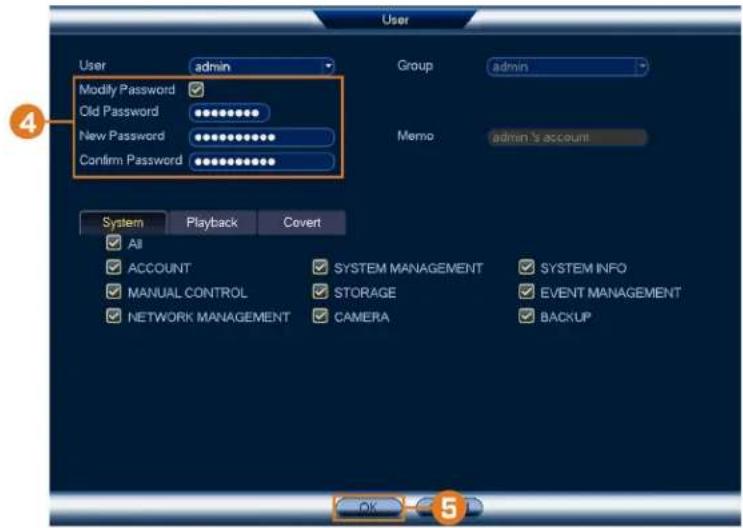
text_image
User User admin Modify Password Old Password New Password Confirm Password Group admin Memo admin's account System Playback Covert All ACCOUNT SYSTEM MANAGEMENT SYSTEM INFO MANUAL CONTROL STORAGE EVENT MANAGEMENT NETWORK MANAGEMENT CAMERA BACKUP OK 5-
Configure the following:
-
Modify Password: Check to modify password.
- Old Password: Enter the current password.
- New Password: Enter the new password you want to use for the system.

NOTE
Passwords for the system must be a minimum of 8 characters, and must include at least 2 of the fi character types: lowercase, uppercase, numeric, and special characters.
- Confirm Password: Re-enter the new password.
- Click OK.
15.1.2 Adding Users
You can allow multiple users to log in to the system. When adding different users, you can what menus they have access to. For example, you may want your friend to monitor your while you are away, while not giving full access to your system.
To add a user:
-
From the Live View display, right-click to open the Quick Menu, then click Main Menu
-
Click X, then click SYSTEM. Click the ACCOUNT tab on the side panel, then click User on the top panel.
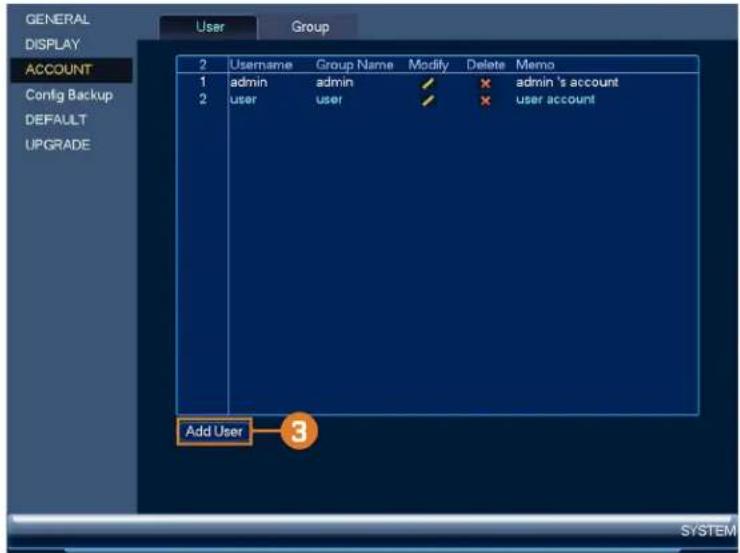
text_image
GENERAL DISPLAY ACCOUNT Config Backup DEFAULT UPGRADE User Group 2 Username Group Name Modify Delete Memo 1 admin admin / × admin's account 2 user user / × user account Add User 3 SYSTEM3. Click Add User.
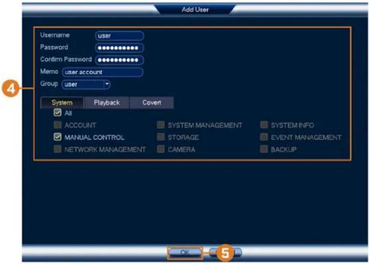
text_image
Add User Username user Password ********** Confirm Password ********** Memo user account Group user System Playback Covert All ACCOUNT SYSTEM MANAGEMENT SYSTEM INFO MANUAL CONTROL STORAGE EVENT MANAGEMENT NETWORK MANAGEMENT CAMERA BACKUP OK 54. Configure the following:
- Username: Enter a name for the user account.
- Password: Enter a password for the user account. Enter the password again under Confirm Password.
- Memo: (Optional) Enter a description of the user account.
- Group: Select the group you would like to assign to this user account. A user account not be given permissions its group does not have.
- Authority: Check the permissions you would like the user account to have. Under the System tab, select the menus the user account may access. Under the Playback tab, select which channels the user account may access recorded video from. Under the Covert tab, select the channels the user account may view live video from.
5. Click OK.
| NOTE |
| Now, you can log in to the system locally, or remotely using the user name and password yo logging into the system with a user account, the user will only have access to the menus you |
15.1.3 Modifying Users
Modify account details, such as account username or permissions.
To modify a user:
- From the Live View display, right-click to open the Quick Menu, then click Main Menu
- Click 📄, then click SYSTEM. Click the ACCOUNT tab on the side panel, then click User on the top panel.
- Click next to the account you want to modify.
- Update account details as needed, then click OK.
15.1.4 Deleting Users
Remove a user from the system.
To remove a user:
- From the Live View display, right-click to open the Quick Menu, then click Main Menu
- Click 📧, then click SYSTEM. Click the ACCOUNT tab on the side panel, then click User on the top panel.
- Click ✗ next to the account you want to delete.
- Click OK.
15.2 Account Groups
Account groups can be used to easily manage permissions for multiple user accounts. User accounts can be given all the permissions of a group, but cannot be given permissions that the does not have.
The system includes the following groups by default:
- admin: Accounts in the admin group are system administrators. They have full access to system, may configure all system settings, and can manage user accounts.
- user: Accounts in the user group are normal users. They have limited access to system r
15.2.1 Adding Groups
Add a new group with unique system permissions.
To add a group:
-
From the Live View display, right-click to open the Quick Menu, then click Main Menu
-
Click 📧, then click SYSTEM. Click the ACCOUNT tab on the side panel, then click User on the top panel.
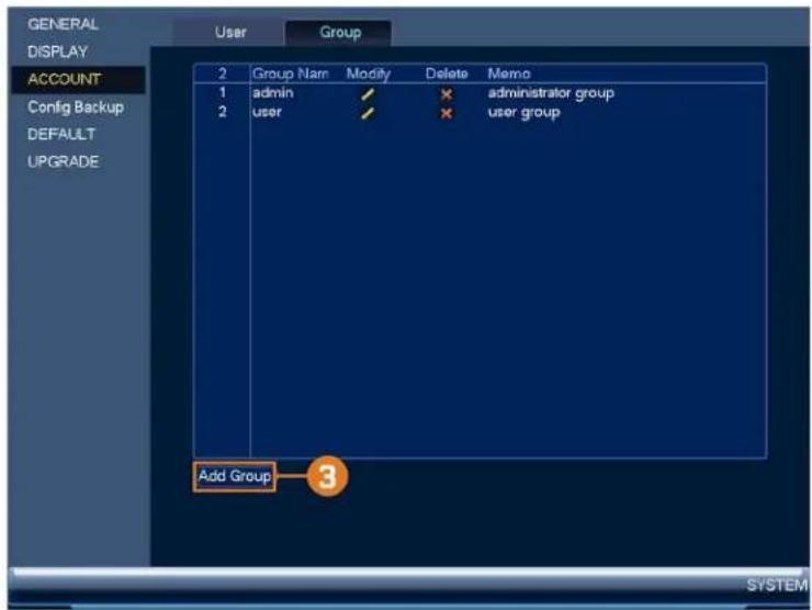
text_image
GENERAL DISPLAY ACCOUNT Config Backup DEFAULT UPGRADE User Group 2 Group Nam Modify Delete Memo 1 admin / × administrator group 2 user / × user group Add Group 3 SYSTEM3. Click Add Group.
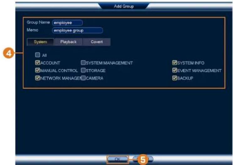
text_image
Add Group Group Name employee Memo employee group System Playback Covert All ACCOUNT SYSTEM MANAGEMENT SYSTEM INFO MANUAL CONTROL STORAGE EVENT MANAGEMENT NETWORK MANAGER CAMERA BACKUP4. Configure the following:
- Group Name: Enter a name for the group.
- Memo: (Optional) Enter a description of the group.
- Authority: Check the permissions you would like the user account to have. Under the System tab, select the menus the user account may access. Under the Playback tab, select which channels the user account may access recorded video from. Under the Covert tab, select the channels the user account may view live video from.
5. Click OK.
15.2.2 Modifying Groups
Change an existing group's name or permissions.
To modify a group:
- From the Live View display, right-click to open the Quick Menu, then click Main Menu
- Click 📄, then click SYSTEM. Click the ACCOUNT tab on the side panel, then click User on the top panel.
- Click next to the group you want to modify.
- Update group details as needed, then click OK.
15.2.3 Deleting Groups
Remove a group.
To delete a group:
- From the Live View display, right-click to open the Quick Menu, then click Main Menu
-
Click 📧, then click SYSTEM. Click the ACCOUNT tab on the side panel, then click User on the top panel.
-
Click ✗ next to the group you want to delete.
- Click OK.
Using the Main Menu16
To open the main menu:
- From the Live View display, right-click to open the Quick Menu, then click Main Menu.

text_image
View 1 View 4 View 8 View 9 PanTill/Zoom Auto Focus Camera Selling Info Sequence Disable Beep Playback Smart Search Manual Device Search Main MenuOR
- From the Live View display, hover the mouse near the bottom of the screen, then click on the Navigation Bar.

16.1 Main Menu Overview
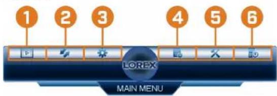
text_image
1 2 3 4 5 6 LOREX MAIN MENU- Playback: Search for and play back recordings, or search for person and/or vehicle detect events. For full details, see 10 Playback, page 28.
- Backup: Export recordings and snapshots to a USB flash drive (not included). For full details, see 11 Backup, page 35.
- Camera: Open the menu to manage IP cameras connected to the network, set recording rameters, and assign custom titles for your cameras.
- Information: View system information.
- Settings: Configure general system settings, recording schedule, motion settings, and more.
- Shutdown: Logout, restart, or shutdown the system.
16.2 Camera Menu
The Camera Menu allows you to manage IP cameras, set recording parameters, and assign titles for your cameras.
16.2.1 Viewing Camera Status
View the connection and alarm status for all connected cameras.
To view camera status:
- From the Live View display, right-click to open the Quick Menu, then click Main Menu

- Click 🧑️, then click REMOTE DEVICE. Click the STATUS tab on the side panel.

text_image
Remote Device STATUS FIRMWARE IPC UPGRADE Channel Status IP Address Video Detect IPC External Alarm Channel N 1 ● 10.1.1.157 -- -- FUR 2 ● 10.1.1.132 -- -- CAM 10 3 ● 10.1.1.151 -- -- CAM 12 4 ● 10.1.1.136 -- -- CAM 27 5 ● 10.1.1.150 -- -- 3MP LNE3 6 ● 10.1.1.135 -- -- CAM 5 7 ● 10.1.1.153 -- -- FUR 8 ● 10.1.1.154 -- -- CAM 1 9 ● 10.1.1.144 -- -- CAM 3 10 ● 10.1.1.134 -- -- CAM 2 11 ● 10.1.1.143 -- -- CAM 7 12 ● 10.1.1.142 -- -- IPC 13 ● 10.1.1.156 -- -- 2MP LNB3 14 ● 10.1.1.155 -- -- CAM 7 15 ● 10.1.1.152 -- -- CAM 8 16 ● 10.1.1.149 -- -- CAM 28 17 ● 192.168.0.71 -- -- CAM 30 18 ● 192.168.0.69 CAM 32 19 192.168.0.77 Refresh Remote Device16.2.2 Camera Firmware Versions
View firmware versions for connected cameras.
To view camera firmware versions:
- From the Live View display, right-click to open the Quick Menu, then click Main Menu
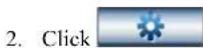
then click REMOTE DEVICE. Click the FIRMWARE tab on the side
- Click

text_image
Remote Device STATUS FIRMWARE IPC UPGRADE Channel IP Address Protocol Type Firmware Vers 1 10.1.1.157 Private N237BE 2.420 2 10.1.1.132 Private PB133F 2.400 3 10.1.1.151 Private LNB3163B 2.420 4 10.1.1.136 Private PE133F 2.400 5 10.1.1.150 Private PE133E 2.420 6 10.1.1.135 Private PB133F 2.400 7 10.1.1.153 Private N237VE 2.420 8 10.1.1.154 Private N233VE 2.420 9 10.1.1.144 Private PB133F 2.400 10 10.1.1.134 Private PB133F 2.400 11 10.1.1.143 Private PB133F 2.400 12 10.1.1.142 Private PE133F 2.400 13 10.1.1.156 Private MCNB3153B 2.212 14 10.1.1.155 Private LNB3143RB 2.400 15 10.1.1.152 Private LNB3163B 2.420 16 10.1.1.149 Private PE133F 2.400 17 192.168.0.71 Private PE133F 2.400 18 192.168.0.69 Private PE133F 2.400 19 192.168.0.77 Private PE133F 2.400 Refresh Remote Device16.2.3 Upgrading Camera Firmware
You can update the firmware for connected IP cameras through the NVR. Firmware upgrade: vide enhanced functionality for the cameras. Typically, a camera firmware upgrade will not be necessary unless directed to do so by technical support.
To upgrade the camera firmware:
- Download the camera firmware file.

NOTE
Make sure that the firmware file you are using is compatible with your IP camera model.
- Extract the firmware file and copy it to a USB thumb drive (not included).
- Insert the USB thumb drive (not included) into a USB port on the system.
-
From the Live View display, right-click to open the Quick Menu, then click Main Menu
-
Click 🙏 then click REMOTE DEVICE. Click the IPC UPGRADE tab on the side panel.

text_image
Remote Device STATUS FIRMWARE IPC UPGRADE Upgrade File Select Device Upgrade(0:32) Device Model None Channel Status IP Address Port Protocol Device Type 1 10.1.1.157 1 Private N237BE 2 10.1.1.132 2 Private PB133F 3 10.1.1.151 3 Private LNB3163B 4 10.1.1.136 4 Private PE133F 5 10.1.1.150 5 Private PE133E 6 10.1.1.135 6 Private PB133F 7 10.1.1.153 7 Private N237VE 8 10.1.1.154 8 Private N233VE 9 10.1.1.144 9 Private PB133F 10 10.1.1.134 10 Private PB133F 11 10.1.1.143 11 Private PB133F 12 10.1.1.142 12 Private PE133F 13 10.1.1.156 13 Private MCNB3153B 14 10.1.1.155 14 Private LNB3143RB 15 10.1.1.152 15 Private LNB3163B Start Upgrade Remote Device- Click Select. Select the firmware file on the USB drive and click OK.
- Check the cameras you would like to apply the upgrade to in the list and then click S Upgrade.
| CAUTION |
| Wait for the firmware upgrade to complete before turning off or unplugging the cameras or N eras will restart during the firmware update process. |
16.2.4 Configuring Snapshot Recording Settings
The system can be set to record snapshot images when a camera detects motion. These sna can be viewed through the Playback menu or can be attached to email alerts and push not. Use the following procedure to set the snapshot parameters for each camera.
| NOTE |
| Snapshot recording must be enabled for motion detection in the Event menu. See 12 Motion Detection, page 42 for details. |
To configure snapshot recording settings:
- From the Live View display, right-click to open the Quick Menu, then click Main Menu

then click RECORDING. Click the Snapshot tab on the top panel.
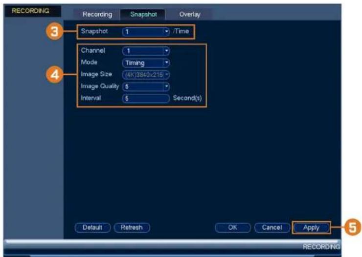
text_image
RECORDING Recording Snapshot Overlay 3 Snapshot 1 /Time Channel 1 Mode Timing Image Size (4K)3840x215 Image Quality 5 Interval 5 Second(s) Default Refresh OK Cancel Apply 5 RECORDING-
Under Snapshot, select the number of snapshots the system will take when the snapshot ton is pressed.
-
Configure the following settings for snapshots saved automatically from motion detection of the snapshot schedule:
-
Channel: Select the channel you would like to configure.
- Mode: Select Timing for the system to take snapshots at fixed intervals throughout the day, or select Trigger for the system to take snapshots only when triggered by motion detection (snapshot recording must be enabled in the motion detection menu - see 12 Motion E tion, page 42 for details).
- Image Size: The image size is the same as the Main Stream resolution of the camera
• Image Quality: Select the snapshot image quality between 1 (lowest) and 6 (highest) -
Interval: Enter the time between snapshots in seconds.
-
Click OK to save changes.
16.2.5 Configuring Video Overlay Settings
The Overlay tab allows you to configure the text and information that appears overtop of the era image, such as time and channel display.
To configure video overlay settings:
-
From the Live View display, right-click to open the Quick Menu, then click Main Menu
-
Click 🙏, then click RECORDING. Click the Overlay tab on the top panel.
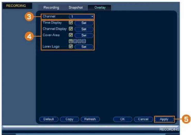
text_image
RECORDING Recording Snapshot Overlay 3 Channel 1 Time Display ✓ Set Channel Display ✓ Set Cover Area ✓ Set Lorex Logo ✓ Set Default Copy Refresh OK Cancel Apply 5 RECORDING-
Under Channel, select the camera you would like to configure.
-
Configure the following settings:
-
Time Display: Check to display the time information during live view. Click Set next to Time Display to choose the position of the time display overlay. Click-and-drag the tin display to reposition it. Right-click when finished.
- Channel Display: Check to display the channel information. Click Set next to Channel Display to choose the position of the channel display overlay. Click-and-drag the channel display to reposition it. Right-click when finished.
- Cover-Area: Check to hide certain parts of the camera image in video recordings. Click the numbered boxes under the Cover-Area checkbox, representing the number of black boxes (masks) that will appear on the camera image. Click Set next to Cover-Area to choose the position of the mask overlay. Click-and-drag masks to reposition them, or and-drag the edges to resize a mask. Right-click to exit the live screen.
-
Lorex Logo: Check to display a Lorex logo watermark on the selected channel. Click Set next to Lorex Logo to choose the position of the logo overlay. Click-and-drag the log reposition it. Right-click when finished.
-
Click OK to save changes.
-
(Optional) Click Copy to copy overlay settings to other channels.
16.2.6 Creating Custom Channel Names
You can assign custom names to your cameras. For example, you can name your cameras 1 on their location (e.g. hallway or front door).
To create custom channel names:
-
From the Live View display, right-click to open the Quick Menu, then click Main Menu
-
Click , then click CHANNEL NAME.

text_image
CHANNEL NAME Camera Name 1 Backyard 1 2 Side Yard 3 Backyard 2 4 Garage 5 Backyard 3 6 Driveway 7 Front Entrance 8 Back Entrance Default Refresh OK Cancel Apply CHANNEL NAME- Click a channel to enter a custom name.
- Click Apply to save changes.
16.3 Information Menu
View system information related to storage, network status, system warnings, and more.
16.3.1 Hard Drive Information
View information related to the hard drives installed in the system, including capacity, status, type.
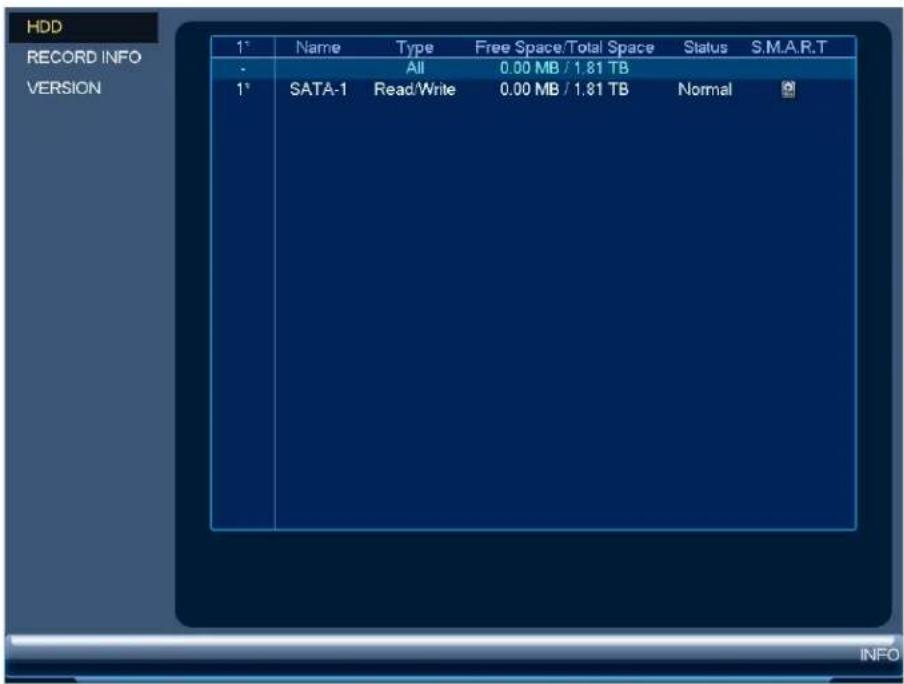
text_image
HDD RECORD INFO VERSION 1° Name Type Free Space/Total Space Status S.M.A.R.T All 0.00 MB / 1.81 TB 1° SATA-1 Read/Write 0.00 MB / 1.81 TB NormalTo access the HDD Info menu:
- From the Live View display, right-click to open the Quick Menu, then click Main Menu
- Click 📄, then click INFO. Click the HDD tab on the side panel.
16.3.2 Recording Information
View start and end times of recordings saved on the hard drive.

text_image
HDD RECORD INFO VERSION Device Model Start Time End Time All 03-30-2019 03:08:45AM 05-02-2019 05:21:03PM 1° SATA-1 03-31-2019 08:04:42PM 04-02-2019 01:45:25AM SATA-1 04-02-2019 01:45:21AM 04-03-2019 06:50:44AM SATA-1 04-03-2019 06:50:39AM 04-03-2019 03:20:14PM SATA-1 04-16-2019 02:47:30PM 04-17-2019 04:02:45PM SATA-1 04-22-2019 01:44:27PM 04-26-2019 05:31:11PM SATA-1 04-29-2019 02:43:19PM 05-01-2019 03:59:54PM SATA-1 05-01-2019 02:59:55PM 05-02-2019 05:21:03PM SATA-1 03-30-2019 03:08:45AM 03-30-2019 02:00:30PM SATA-1 03-30-2019 02:00:27PM 03-31-2019 08:04:46PMTo access the Record Info menu:
- From the Live View display, right-click to open the Quick Menu, then click Main Menu
- Click 📄, then click INFO. Click the RECORD INFO tab on the side panel.
16.3.3 Version Information
View system information such as device ID, model number, IP address, and firmware version
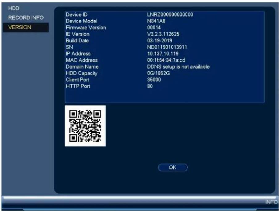
text_image
HDD RECORD INFO VERSION Device ID LNRZ000000000000 Device Model N841A8 Firmware Version 00014 IE Version V3.2.3.112625 Build Date 03-19-2019 SN ND011901013911 IP Address 10.137.10.119 MAC Address 00:1f:54:34:7a:cd Domain Name DDNS setup is not available HDD Capacity 0G/1862G Client Port 35000 HTTP Port 80 OK INFOTo access the Version Info menu:
- From the Live View display, right-click to open the Quick Menu, then click Main Menu
- Click 📄, then click INFO. Click the VERSION tab on the side panel.
16.3.4 Event Information
View a summary of active system alarms. Activated alarms are highlighted in white. Addition: info such as channels that are currently detecting motion is shown.

text_image
EVENT Device Status Device(NIC No.:1,HDD No.:1) No HDD HDD Error Disk full IP Conflict Net Disconnect MAC Conflict Channel Status Channel(CH:8) Video Loss Motion Detect EVENTThe following alarms are shown in the Alarm Status menu:
• No HDD: No hard drive is detected.
• HDD Error: Hard drive error detected.
- Disk Full: Hard drive is full.
- IP Conflict: More than one device on the network is using the same IP address.
- Net Disconnect: System is not connected to the network.
- MAC Conflict: More than one device on the network is using the same MAC address.
• Video Loss: Shows disconnected channels.
- Motion Detect: Shows channels with active motion alarms.
To access the event information menu:
-
From the Live View display, right-click to open the Quick Menu, then click Main Menu
-
Click , then click EVENT.
16.3.5 Online Users
View all users connected to the system using computers or mobile devices.

text_image
ONLINE USERS Network Load TEST Username IP Address User Login Time Block Block Time 60 s NETWORKTo access the online users menu:
- From the Live View display, right-click to open the Quick Menu, then click Main Menu
- Click 📄, then click NETWORK. Click the ONLINE USERS tab on the side par
16.3.6 Network Load
View network traffic your system is sending and receiving.
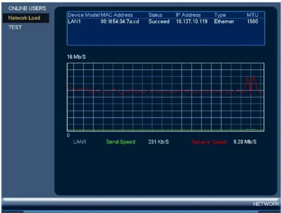
line
| Device Model MAC Address | Status | IP Address | Type | MTU | | ------------------------ | ------ | ---------- | ---- | --- | | LAN1 | Succeed | 10.137 | Ethernet | 1500 |To access the network load menu:
- From the Live View display, right-click to open the Quick Menu, then click Main Menu
- Click , then click NETWORK. Click the Network Load tab on the side panel.
16.3.7 Network Test
Test if your system can connect to other devices over the LAN or Internet. You can enter dress of a device and click Test to determine if your system can connect to it.
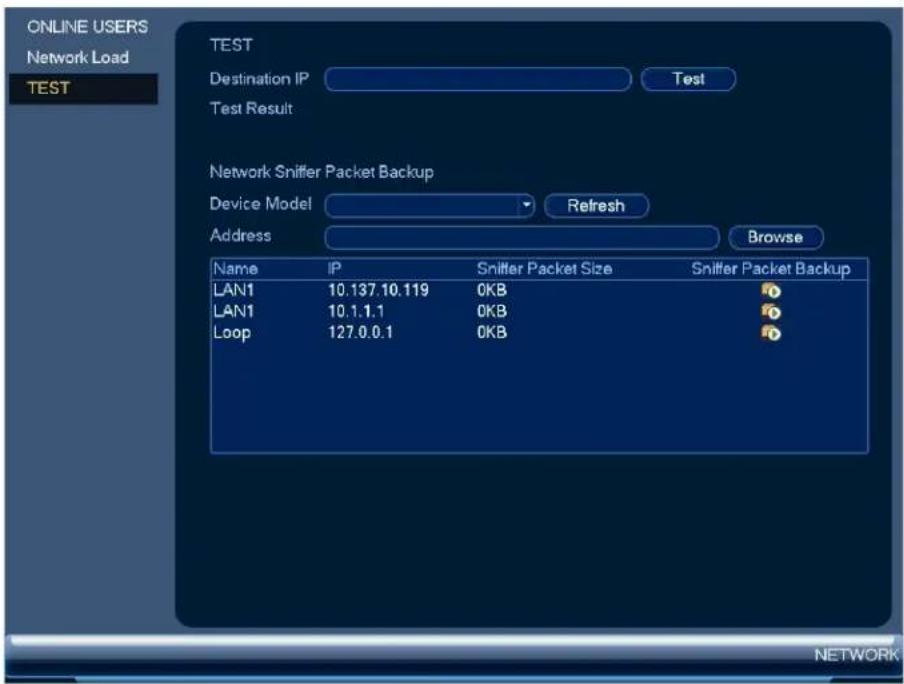
text_image
ONLINE USERS Network Load TEST TEST Destination IP Test Test Result Network Sniffer Packet Backup Device Model Refresh Address Browse Name IP Sniffer Packet Size Sniffer Packet Backup LAN1 10.137.10.119 0KB LAN1 10.1.1.1 0KB Loop 127.0.0.1 0KBTo access the network test menu:
-
From the Live View display, right-click to open the Quick Menu, then click Main Menu
-
Click 📄, then click NETWORK. Click the TEST tab on the side panel.
16.3.8 BPS
Shows bitrates of connected cameras. The bitrate is the amount of data the camera is sending the system.

line
| Channel | Kbps | Resolution | Wave | | :--- | :--- | :--- | :--- | | 1 | 4488 | 3840*2160 | [---] | | 2 | 4189 | 3840*2160 | [---] | | 3 | 3208 | 3840*2160 | [---] | | 4 | 3654 | 3840*2160 | [---] | | 5 | 4488 | 3840*2160 | [---] | | 6 | 4189 | 3840*2160 | [---] | | 7 | 3654 | 3840*2160 | [---] | | 8 | 4189 | 3840*2160 | [---] |To access the BPS menu:
-
From the Live View display, right-click to open the Quick Menu, then click Main Menu
-
Click, then click BPS.
16.3.9 System Log
Search for system logs in a certain time range.
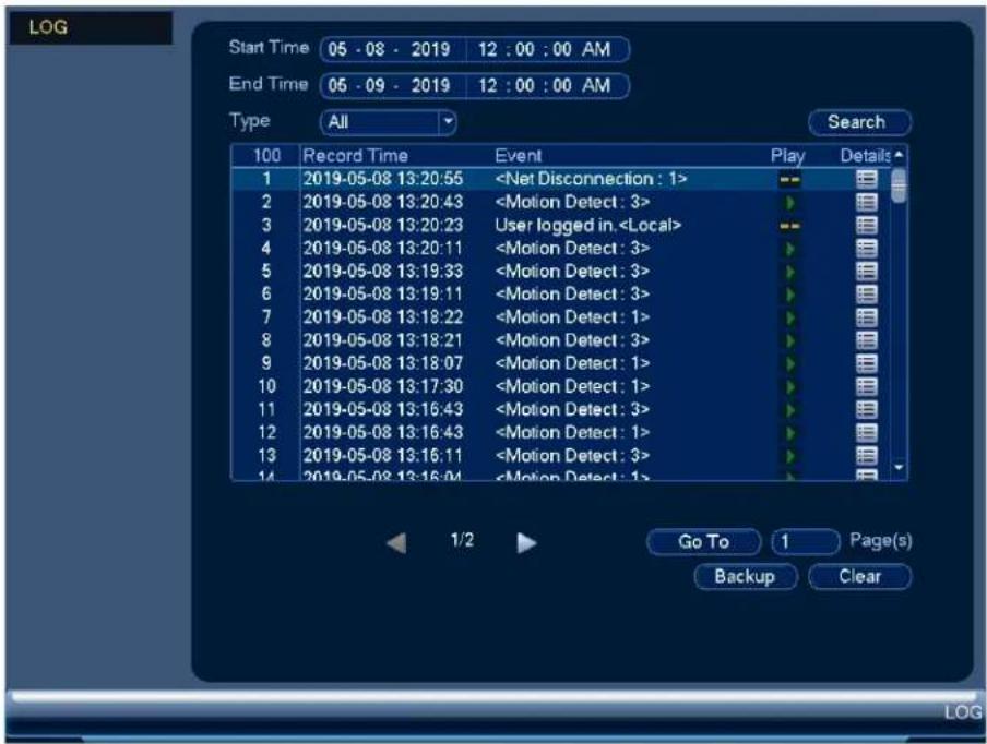
text_image
LOG Start Time 05 - 08 - 2019 12 : 00 : 00 AM End Time 05 - 09 - 2019 12 : 00 : 00 AM Type All Search 100 Record Time Event Play Details 1 2019-05-08 13:20:56To access the log menu:
-
From the Live View display, right-click to open the Quick Menu, then click Main Menu
-
Click, then click LOG.
16.4 Settings Menu
Configure general system settings, recording schedule, motion settings, and more.
16.4.1 Selecting DHCP or Static IP Address (TCP/IP)
Configure IP address settings.
To configure IP address settings:
- From the Live View display, right-click to open the Quick Menu, then click Main Menu

- Click then click NETWORK. Click the TCP/IP tab on the side panel.
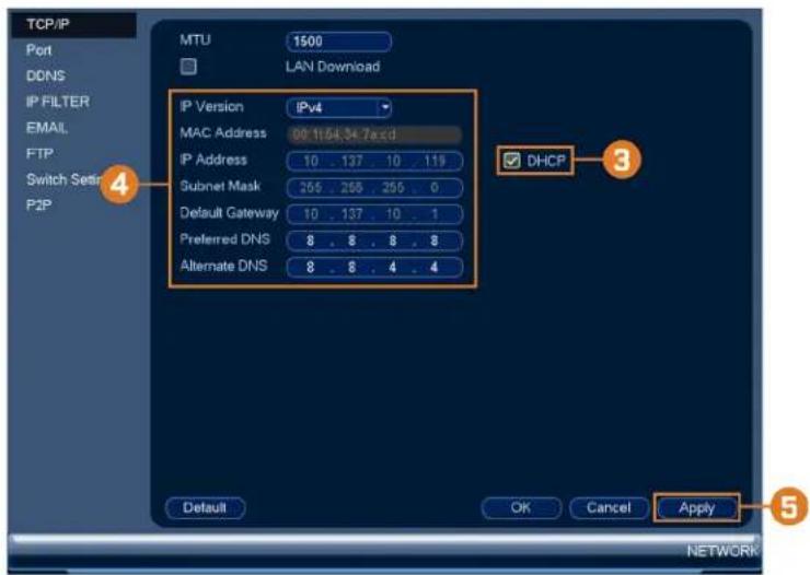
text_image
TCP/IP Port DDNS IP FILTER EMAIL FTP Switch Set: P2P MTU 1500 LAN Download IP Version IPv4 MAC Address 00:11/64.34.7abcd IP Address 10 137 10 119 Subnet Mask 265 268 255 0 Default Gateway 10 137 10 1 Preferred DNS 8 8 8 8 Alternate DNS 8 8 4 4 DHCP Default OK Cancel Apply 5 NETWORK- Check DHCP (recommended) to let the system automatically obtain an IP address from the router.
OR
Uncheck DHCP to assign a static IP address (advanced users only).
- If you uncheck DHCP, configure the following:
• IP Version: Select IPv4 or IPv6.
- IP Address: Enter the IP address you would like to assign to the system. Make sure other device on your network is using the same IP address.
- Subnet Mask: Enter the subnet mask for your network.
- Default Gateway: Enter the gateway address for your network.
- Preferred DNS: Enter the address of your primary DNS server.
- Alternate DNS: Enter the address of your secondary DNS server.
- Click Apply to save changes.
16.4.2 Configuring System Ports (Connection)
Configure ports used by the system for remote connectivity. If you are using DDNS connect port forwarding is required for the HTTP Port (default: 80) and TCP (Client) Port (default: 35000).
| NOTE |
| Port forwarding is not required unless you are using DDNS for remote access. Using mobile apps port forwarding or DDNS setup. |
To configure system ports:
- From the Live View display, right-click to open the Quick Menu, then click Main Menu

- Click then click NETWORK. Click the Port tab on the side panel.
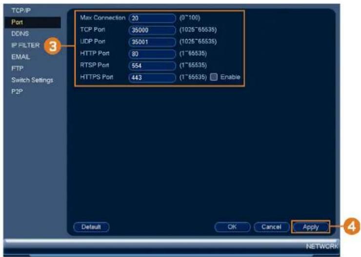
text_image
TCP/IP Port DDNS IP FILTER EMAIL FTP Switch Settings P2P Max Connection 20 (0~100) TCP Port 35000 (1025~65535) UDP Port 35001 (1025~65535) HTTP Port 80 (1~65535) RTSP Port 554 (1~65535) HTTPS Port 443 (1~65535) Enable Default OK Cancel Apply 4 NETWORK- Configure the port numbers as needed.
- Click Apply to save changes.

NOTE
Up to 3 devices may connect to the system at the same time.
16.4.3 Configuring IP Filter
Configure permissions for external IP addresses attempting to access the unit.
-
From the Live View display, right-click to open the Quick Menu, then click Main Menu
-
Click 📧, then click NETWORK. Click the IP FILTER tab on the side panel.
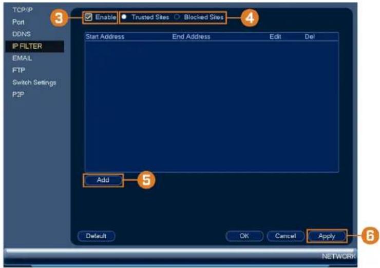
text_image
TCP/IP Port DDNS IP FILTER EMAIL FTP Switch Settings P2P 3 Enable • Trusted Sites ○ Blocked Sites 4 Start Address End Address Edit Del Add 5 Default OK Cancel Apply 6 NETWORK- Check Enable.
- Select Trusted Sites to add IP addresses or ranges that are permitted to access the recorder, or select Blocked Sites to add IP addresses or ranges that are not permitted to access the recorder.
- Click Add to enter an IP address or range.
- Click Apply when finished.
16.4.4 Configuring Email Alerts
You can configure the system to send out email alerts for motion detection or other events.
| NOTE |
| To send out motion detection alerts, you must enable the Send Email option for motion detection on each camera you would to receive alerts from. For details, see 12 Motion Detection, page 42. |
To configure Email Alerts:
- From the Live View display, right-click to open the Quick Menu, then click Main Menu
- Click 📧, then click NETWORK. Click the EMAIL tab on the side panel.
- Check Enable to enable email notifications.
If you want to use Lorex's email server (recommended):
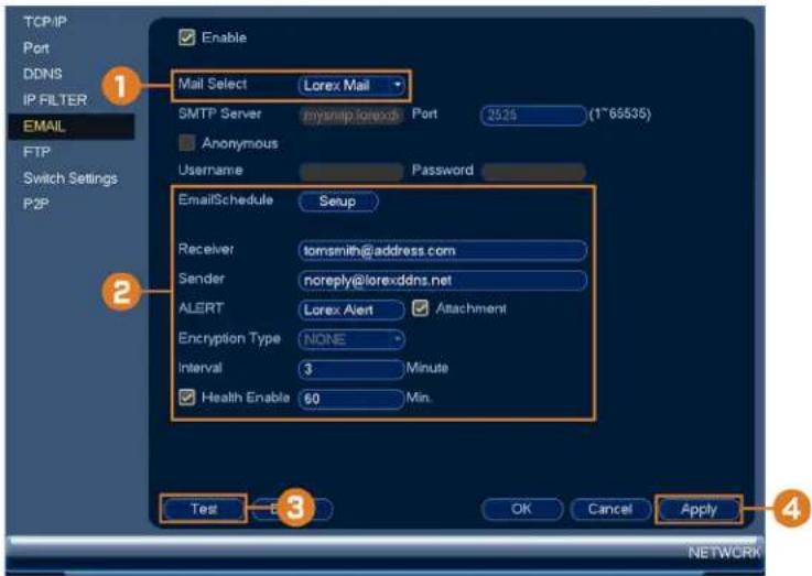
text_image
TCP/IP Port DDNS IP FILTER EMAIL FTP Switch Settings P2P Enable Mail Select Lorex Mail SMTP Server myriplorexx Port 25.25 (1~65535) Anonymous Username Password EmailSchedule Setup Receiver tomsmith@address.com Sender noreply@lorexddns.net ALERT Lorex Alert Attachment Encryption Type NONE Interval 3 Minute Health Enable 60 Min. Test OK Cancel Apply 4 NETWORK- Under Mail Select, select Lorex Mail to use the Lorex email server to send out alarm notifications. This is the recommended setting.
2. Configure the following:
- Email Schedule: Configure time periods during which email alerts will be sent.
- Receiver: Enter the email address that will receive alerts.
- Sender: Enter the sender's email address.
- ALERT: Enter the subject line for the email alert.
- Attachment: Check to include an image attachment of the camera.

NOTE
You must enable the Snapshot option for motion detection on each camera you would to receive attachments. For details, see 12 Motion Detection, page 42.
- Interval: Enter the interval between alert emails.
-
Health Enable: Check to enable health check emails. Health check emails will be sent riodically to ensure that the system is functioning normally. Enter the interval in minu for health check emails.
-
Click Test to send a test email.
- Click Apply to save settings.
If you want to use your own email server (advanced):

text_image
TCP/IP Port DDNS IP FILTER EMAIL FTP Switch Settings P2P Enable Mail Select Customize SMTP Server mysmtp.lorexd Port 2525 (1~65535) Anonymous Username myusername Password ************ EmailSchedule Setup Receiver tomsmith@address.com Sender sender@address.com ALERT Lorex Alert Attachment Encryption Type SSL Interval 3 Minute Health Enable 60 Min. Test OK Cancel Apply 4 NETWORK-
Under Mail Select, select Customize.
-
Configure the following:
-
SMTP Server: Enter the SMTP server address.
- Port: Enter the port used by the SMTP server.
- Anonymous: Check if your server supports anonymous log ins. Otherwise, leave this unchecked.
- User: Enter the SMTP user name.
- Password: Enter the SMTP password.
- Receiver: Enter the email address that will receive alerts.
- Sender: Enter the sender's email address.
- ALERT: Enter the subject line for the email alert.
- Attachment: Check to include an image attachment of the camera.

NOTE
You must enable the Snapshot option for motion detection on each camera you would to receive attachments. For details, see 12 Motion Detection, page 42.
- Encryption Type: Select SSL or TLS if your server uses encryption. Select None if your server does not use encryption.
- Interval: Enter the interval between alert emails.
-
Health Enable: Check to enable health check emails. Health check emails will be sent riodically to ensure that the system is functioning normally. Enter the interval in minu for health check emails.
-
Click Test to send a test email.
- Click Apply to save settings.
16.4.5 FTP (Advanced)
Send recordings and/or snapshots to an FTP server.
To configure FTP settings:
- From the Live View display, right-click to open the Quick Menu, then click Main Menu

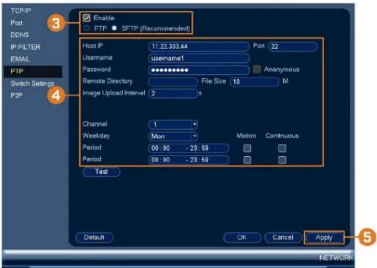
text_image
TCP/IP Port DONS IP FILTER EMAIL FTP Switch Settings P2P Enable FTP SFTP (Recommended) Host IP 11.22.333.44 Port 22 Username username1 Password ********** Anonymous Remote Directory File Size 10 M Image Upload Interval 2 Channel 1 Weekday Mon Motion Continuous Period 00:00 -23:59 Period 00:00 -23:59 Test Default OK Cancel Apply 3 4 5 NETWORK-
Check Enable to allow FTP connection, and select either FTP or SFTP depending on your configuration.
-
Configure the following:
-
Host IP: Enter the FTP server's address.
- Port: Enter the FTP port.
- Username: Enter your FTP username.
- Password: Enter your FTP password.
- Anonymous: Enable if your FTP server supports anonymous login.
- Remote Directory: Enter the directory to save recordings and/or snapshots to.
- File Length: Enter the recording file length in minutes.
- Image Upload Interval: Enter the interval between snapshots in seconds.
- Channel: Select a channel to set FTP recording preferences for.
- Weekday: Select a day of the week to configure FTP recording settings for, or select All to apply to all days of the week.
- Period: Select up to 2 periods of time where the system will save recordings to the Check Motion or Continuous beside each period to determine which recording type will be uploaded to the FTP.
5. Click Apply.
16.4.6 Configuring Switch Settings (Advanced)
Configure the networking settings for the internal PoE switch.

CAUTION
It is recommended to leave this menu on the default settings. Changing the information in this menu may d the connection to the cameras.
To configure switch settings:
-
From the Live View display, right-click to open the Quick Menu, then click Main Menu
-
Click 📧, then click NETWORK. Click the Switch Settings tab on the side panel
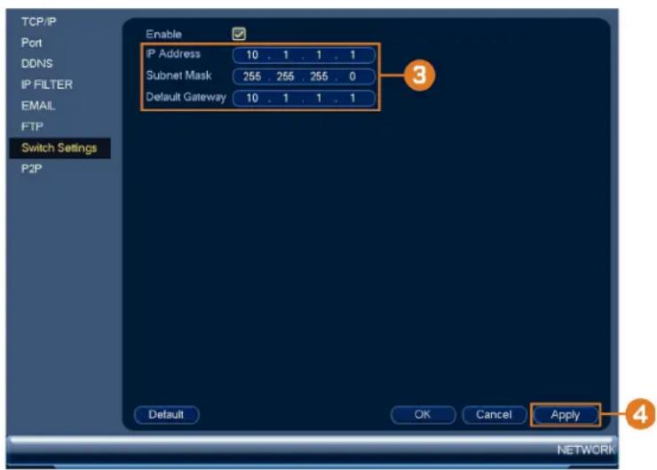
text_image
TCP/IP Port DDNS IP FILTER EMAIL FTP Switch Settings P2P Enable IP Address 10 . 1 . 1 . 1 Subnet Mask 255 . 255 . 255 . 0 Default Gateway 10 . 1 . 1 . 1 3 Default OK Cancel Apply 4 NETWORK- Configure the IP Address, Subnet Mask, and Default Gateway for the internal PoE switch.
- Click OK. Click Save to save changes. The system will restart.
16.4.7 P2P Setting
The P2P Setting menu is used only to enable / disable remote access to the system using connection.
| CAUTION |
| P2P connection is the primary method used for remote access to your security system using the Lo If you disable P2P connectivity, you will only be able to access your system over the Internet usi DDNS Setup (Advanced), page 112 for details. |
To change P2P setting:
- From the Live View display, right-click to open the Quick Menu, then click Main Menu
- Click 📧, then click NETWORK. Click the P2P tab on the side panel.
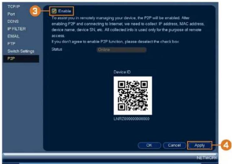
text_image
TCP/IP Port DDNS IP FILTER EMAIL FTP Switch Settings P2P 3 Enable To assist you in remotely managing your device, the P2P will be enabled. After enabling P2P and connecting to Internet, we need to collect IP address, MAC address, device name, device SN, etc. All collected info is used only for the purpose of remote access. If you don't agree to enable P2P function, please deselect the check box Status Online Device ID LNRZ000000000000 OK Cancel Apply 4 NETWORK- Check Enable to use P2P, or uncheck to disable.
- Click Apply.
16.4.8 Configuring Video Loss Settings
Configure video loss settings and how the system reacts to a video loss event. Video loss is that video from one or more cameras was interrupted or disabled. It could be caused by a of factors, such as a loose or damaged connection, loss of power to a camera, or a block lens.
To configure video loss settings:
-
From the Live View display, right-click to open the Quick Menu, then click Main Menu
-
Click 📧, then click EVENT. Click the MOTION tab on the side panel, then click the Video Loss tab on the top panel.

text_image
MOTION WARNING 3 Camera 1 Enable Schedule Set Show Message Send Email Record Channel PTZ Activation Set Post_REC 10 s Sequence Snapshot Buzzer Default Copy Refresh OK Cancel Apply EVENT-
Under Camera, select the channel you would like to configure.
-
Check Enable to enable video loss events for the selected channel.
-
Configure the following to customize settings for video loss events:
- Schedule: Click Set to configure a schedule for video loss events. It is recommended to leave this on the default setting, so you can be alerted at any time one of your car video.
- Show Message: Check to show a popup message on the monitor if one of your came loses video.
- Send Email: Check to enable email alerts. You must configure email alerts before you be able to receive them (see 16.4.4 Configuring Email Alerts, page 77).
- Record Channel: Click the checkbox to enable video recording when video loss occurs. You can then select the channels the system will record when video loss occurs on 1 rently selected channel.
- PTZ Activation: Check to enable PTZ actions when video loss occurs (PTZ camera required; not included). Click Set to select which PTZ actions will be taken by each c
- Post_REC: Enter the number of seconds the system will record after video loss occurs
- Sequence: Check to enable a custom sequence mode when motion is detected on the elected channel. Then click the channels you would like to display in the custom seq mode.
- Snapshot: Click the box to enable snapshot recording when video loss occurs. You can then select which channels will save snapshots when video loss occurs on the current lected channel.
- Buzzer: Check to enable the system buzzer when video loss occurs on the currently selected channel.
- Click Apply to save changes.
16.4.9 Configuring Hard Drive Warnings
Hard drive warnings will notify you if an issue is detected with the hard drive.
To configure hard drive warnings:
-
From the Live View display, right-click to open the Quick Menu, then click Main Menu
-
Click 📧, then click EVENT. Click the WARNING tab on the side panel, then click the HDD tab on the top panel.

text_image
MOTION WARNING HDD Network Event Type No HDD Enable ✓ Show Message Send Email Buzzer OK Cancel Apply EVENT- Under Event Type, select the hard drive event you would like to configure. Check Enable to activate the selected warning.
• No HDD: No hard drive detected.
- Disk Error: A hard drive error has been detected.
- Disk Full: The hard drive is full or almost full. You can enter the percentage of disk remaining that will trigger a warning under Less Than (e.g. when less than 10% of t drive is empty, trigger a warning). Disk Full warnings will not occur if overwrite is
- All: Configure warnings for all hard drive events.
- Configure the responses the system will take when the selected event occurs:
• Show Message: Show a popup message on the monitor.
- Send Email: Check to enable email alerts. You must configure email alerts before you be able to receive them (see 16.4.4 Configuring Email Alerts, page 77).
- Buzzer: Check to activate the system buzzer.
- Click Apply to save changes.
16.4.10 Configuring Network Warnings
Network warnings will notify you if there your system loses connection to the Internet or I network or if there is an issue on your network.
To configure network warnings:
- From the Live View display, right-click to open the Quick Menu, then click Main Menu

- Click 📄 then click EVENT. Click the WARNING tab on the side panel, then click the Network tab on the top panel.
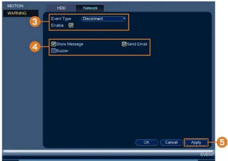
text_image
MOTION WARNING HDD Network Event Type Disconnect Enable Show Message Send Email Buzzer OK Cancel Apply 3 4 5-
Under Event Type, select the event type you would like to configure. Check Enable to activate the selected warning.
-
Net Disconnection: The system has lost connection to the network.
• IP Conflict: More than one device on your network has the same IP address.
• MAC Conflict: More than one device on your network has the same MAC address. -
All: Configure responses for all network events.
-
Configure the following for the selected event type:
-
Show Message: Check to show a popup message when the selected event occurs.
- Send Email: Check to enable email alerts. You must configure email alerts before you be able to receive them (see 16.4.4 Configuring Email Alerts, page 77).
-
Buzzer: Check to activate the system buzzer.
-
Click Apply to save changes.
16.4.11 Configuring Pre-Recording
The system can pre-record video when motion detection events occur. This will ensure that system records the entire event when motion is detected. By default, the system pre-records onds of video every time motion is detected.
| NOTE |
| Ensure you have set your preferences for motion detection (see 12 Motion Detection, page 42 for details). |
To configure pre-recording:
- From the Live View display, right-click to open the Quick Menu, then click Main Menu

- Click X, then click STORAGE. Click the SCHEDULE tab on the side panel.
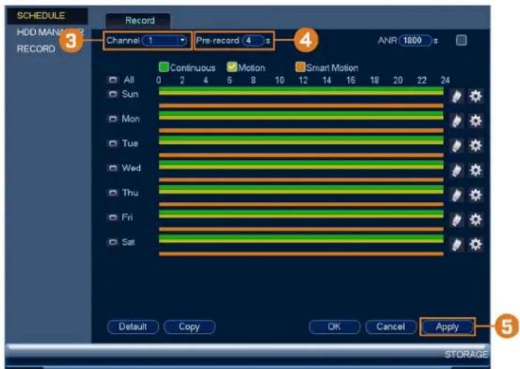
text_image
SCHEDULE HDD MAN 2 3 RECORD Record Channel 1 Pre-record 4 ANR 1800 s Continuous Motion Smart Motion All 0 2 4 6 8 10 12 14 16 18 20 22 24 Sun Mon Tue Wed Thu Fri Sat Default Copy OK Cancel Apply 5 STORAGE- Under Channel, select the camera you would like to configure or select All.
- Under PreRecord, select the duration for pre-recording.
- Click OK to save settings.
16.4.12 Formatting the Hard Drive
Format the hard drive to erase all saved data. If you install a new hard drive, you must find hard drive using the procedure below before you will be able to record.
To format the hard drive:
| CAUTION |
| Formatting the hard drive erases all data on the hard drive. Formatting cannot be undone. |
- From the Live View display, right-click to open the Quick Menu, then click Main Menu

- Click 📄, then click STORAGE. Click the HDD MANAGER tab on the side pan

text_image
SCHEDULE HDD MANAGER RECORD SATA 1 Name Type Status Free Space/Total Space SATA-1 Read/Write Normal 0.00 MB/1.81 TB 4 ash→ Format OK Cancel Apply STORAGE- Select the hard dive you would like to format.
- Click Format, then click Yes to confirm.
16.4.13 Configuring Hard Drive Type
The system supports the following hard drive types:
- Read/Write: Normal recording hard drive.
- Read-Only: The system can playback data from this hard drive, but it will not record to
To set the hard drive type:
- From the Live View display, right-click to open the Quick Menu, then click Main Menu

- Click X, then click STORAGE. Click the HDD MANAGER tab on the side pan

text_image
SCHEDULE HDD MANAGER RECORD SATA 1 0 Name Type Status.Free Space/Total Space SATA-1 Read/Write Normal 0.00 MB/1.81 TB Refresh Format OK Cancel Apply 4 STORAGE- Select the hard drive type under the Type column next to the hard drive you would like to configure.
- Click Apply to save changes. The system will restart to complete this operation.
16.4.14 Configuring Holidays
You can set certain days as holidays. Holidays have a special recording schedule.
To configure holidays:
-
From the Live View display, right-click to open the Quick Menu, then click Main Menu
-
Click 📄, then click SYSTEM. Click the GENERAL tab on the side panel, then click the Holiday tab on the top panel.
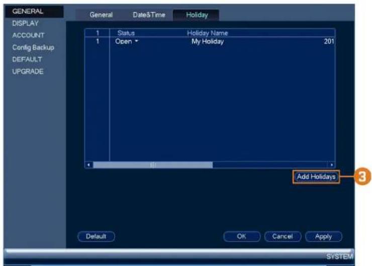
text_image
GENERAL DISPLAY ACCOUNT Config Backup DEFAULT UPGRADE General Date&Time Holiday 1 Status Holiday Name 1 Open My Holiday 201 Add Holidays Default OK Cancel Apply SYSTEM-
Click Add Holidays.
-
Configure the following:
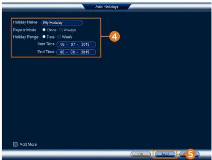
text_image
Add Holidays Holiday Name My Holiday Repeat Mode Once Always Holiday Range Date Week Start Time 05 - 07 - 2019 End Time 05 - 08 - 2019 Add More OK Add• Holiday Name: Enter a name for this holiday.
- Repeat Mode: Select Once for the holiday to occur only this year or Always for the holiday to be repeated each year.
- Holiday Range: Select Date to select a specific date, or select Week to select holidays based on which week they fall on.
- Click Add. Now that you have added a holiday, an extra holiday setting is added to the recording schedule.
| NOTE |
| You cannot delete holidays, but you can disable them by selecting Off under the Status drop-down, then click Apply. |
16.4.15 Configuring General System Settings
Configure miscellaneous system settings.
To configure general settings:
- From the Live View display, right-click to open the Quick Menu, then click Main Menu

- Click 📄, then click SYSTEM. Click the GENERAL tab on the side panel, then click the General tab on the top panel.
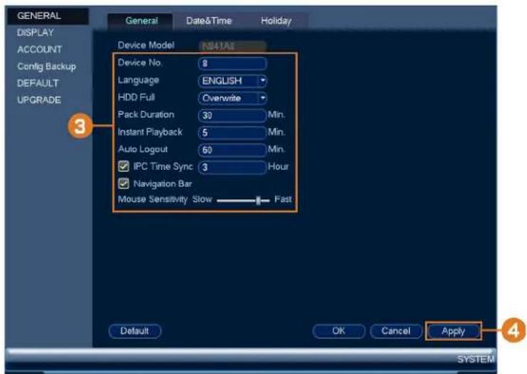
text_image
GENERAL DISPLAY ACCOUNT Config Backup DEFAULT UPGRADE General Date&Time Holiday Device Model N941AI Device No. 8 Language ENGLISH HDD Full Overwrite Pack Duration 30 Min. Instant Playback 5 Min. Auto Logout 60 Min. IPC Time Sync 3 Hour Navigation Bar Mouse Sensitivity Slow Fast Default OK Cancel Apply SYSTEM- Configure the following:
• Device No.: Not supported.
- Language: Set the system languages. Available options are English, French, and Spanish
- Video Standard: Select NTSC (North America) or PAL (Europe).
- HDD Full: Select Overwrite for the system to overwrite the oldest recordings when the hard drive is full or select Stop Record for the system to stop recording when the h drive is full.
- Pack Duration: Set the length of time (in minutes) for video files saved to the hard. For example, if set to 30 minutes, the system will create a new video file for every nutes of continuous recording.
- Instant Playback: Select the amount of time (in minutes) the system will go back wh stant playback is activated in live view.
- Auto Logout: Select the idle time (in minutes) before the system will logout the current user.
- IPC Time Sync: Select how often (in hours) the NVR will update the time on the II cameras.
- Navigation Bar: Check to enable the Navigation Bar that comes up when you left click live view.
- Mouse Sensitivity: Use the slider to adjust the mouse speed.
- Click Apply to save changes.
16.4.16 Setting the Monitor Resolution (Display)
Configure the system's monitor resolution and other display settings.
To set the monitor resolution:
- From the Live View display, right-click to open the Quick Menu, then click Main Menu

- Click 📄, then click SYSTEM. Click the DISPLAY tab on the side panel, then click the Display tab on the top panel.
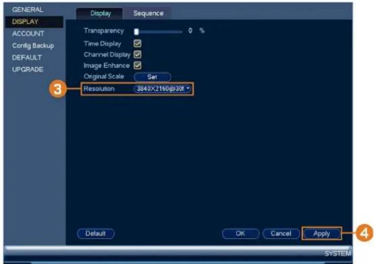
text_image
GENERAL DISPLAY ACCOUNT Config Backup DEFAULT UPGRADE Display Sequence Transparency 0 % Time Display ✓ Channel Display ✓ Image Enhance ✓ Original Scale Set Resolution 3840×2160@30ft Default OK Cancel Apply SYSTEM- Under Resolution, select the correct resolution for your monitor.
- Click Apply to save changes. Click OK again to restart the system using the new resolution.
To configure other display settings:
- From the Live View display, right-click to open the Quick Menu, then click Main Menu
- Click 📄, then click SYSTEM. Click the DISPLAY tab on the side panel, then click the Display tab on the top panel.

text_image
GENERAL DISPLAY ACCOUNT Config Backup DEFAULT UPGRADE Display Sequence Transparency 0 % Time Display ✓ Channel Display ✓ Image Enhance ✓ Original Scale Set Resolution 3840X2160@30f Default OK Cancel Apply SYSTEM 4-
Configure the following:
-
Transparency: Select the menu transparency.
- Time Display: Check to show the time on the monitor.
- Channel Display: Check to show the channel names on the monitor.
- Image Enhance: Check for the system to digitally improve the video quality on the list display. This setting does not affect recordings.
-
Original Scale: Set the system to show the true aspect ratio of the cameras on the lplay. This may add black bars on the top and bottom of the image.
-
Click Apply to save changes.
16.4.17 Configuring Sequence Mode
Sequence mode cycles through connected channels to give you an overview of what is happy on all cameras. You can customize the order that channels appear in Sequence mode, as we configure which viewing modes should be used.
To configure Sequence mode:
-
From the Live View display, right-click to open the Quick Menu, then click Main Menu
-
Click 📧, then click SYSTEM. Click the DISPLAY tab on the side panel, then click the Sequence tab on the top panel.

text_image
GENERAL DISPLAY ACCOUNT Config Backup DEFAULT UPGRADE 3 Video Detection View 1 Enable Sequence Dwell 5 s Window Split View 4 2 Window Split 1 1 2 3 4 2 5 6 7 8 Add Del Move up Move down Default OK Cancel Apply SYSTEM- Choose how many channels will appear on screen when Sequence mode is triggered by a motion detection (you must check Sequence when configuring motion detection — see 12 Motion Detection, page 42 for details).
- Enter the amount of time in seconds that each channel or page will appear on screen d Sequence mode.
- Select a viewing mode to configure. It is recommended to start with View 1 and make way to View 9. By default, all viewing modes are included in the Sequence mode cycle
- Configure the order of channels shown on screen for each viewing mode. Uncheck channel groups that you want to remove from the Sequence mode cycle.
- Click Apply.
16.4.18 Saving Your System Configuration to a USB Thumb Drive
The system allows you to save your current system configuration to a USB thumb drive (ncluded). This is useful if you want to backup your current settings.
| NOTE |
| This function only saves settings created in system menus. It does not save or backup any video. |
To save your system configuration to a USB thumb drive:
-
From the Live View display, right-click to open the Quick Menu, then click Main Menu
-
Click X, then click SYSTEM. Click the Config Backup tab on the side panel.
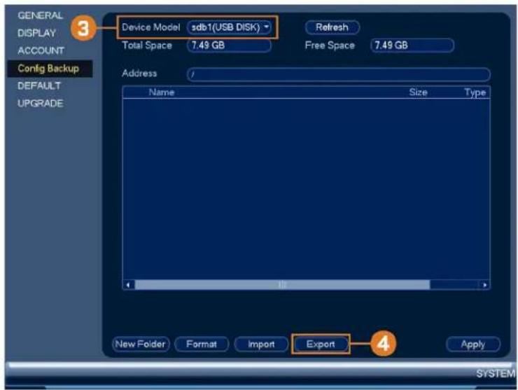
text_image
GENERAL DISPLAY ACCOUNT Config Backup DEFAULT UPGRADE 3 Device Model sdb1(USB DISK) Total Space 7.49 GB Refresh Free Space 7.49 GB Address Name Size Type New Folder Format Import Export Apply SYSTEM- Under Device Model, select the USB device where you would like to save the configura
- Click EXPORT to save your current system configuration.
To restore a saved system configuration:
- From the Live View display, right-click to open the Quick Menu, then click Main Menu

- Click 📧, then click SYSTEM. Click the Config Backup tab on the side panel.

text_image
GENERAL DISPLAY ACCOUNT Config Backup DEFAULT UPGRADE 3 Device Model sdb1(USB DISK) Total Space 7.49 GB Refresh Free Space 7.48 GB Address Name Size Type System Volume Information Folde Config_NVR_20190508132212 Folde New Folder Format Import Apply SYSTEM- Under Device Model, select the USB device where the system configuration is saved.
- Click the folder with the configuration file you would like to restore. Configuration file are labeled "Config" and then the time and date the configuration was saved (e.g., Conf, 20140425103727).
- Click Import to restore the system configuration.
- Click OK to confirm. The system will restart to complete the operation.
16.4.19 Restore Default Settings
Restore the system to its default settings.
To restore default settings:
-
From the Live View display, right-click to open the Quick Menu, then click Main Menu
-
Click 📧, then click SYSTEM. Click the DEFAULT tab on the side panel.
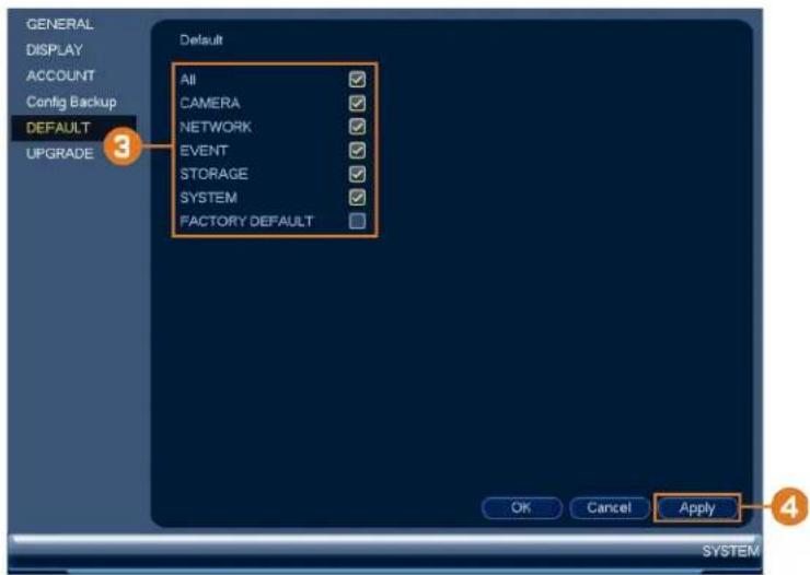
text_image
GENERAL DISPLAY ACCOUNT Config Backup DEFAULT UPGRADE Default All CAMERA NETWORK EVENT STORAGE SYSTEM FACTORY DEFAULT OK Cancel Apply SYSTEM- Check the menus you would like to reset to default settings.
- Click OK.
16.4.20 Upgrading Firmware Manually
The primary method for upgrading system firmware is automatically over the Internet. The s: also supports firmware upgrades from a USB thumb drive (not included).
Prerequisite:
- Save the .bin firmware file for your unit onto a USB flash drive (not included), and connect the drive to one of the system's free USB ports.
To upgrade firmware manually:
-
From the Live View display, right-click to open the Quick Menu, then click Main Menu
-
Click X, then click SYSTEM. Click the UPGRADE tab on the side panel.
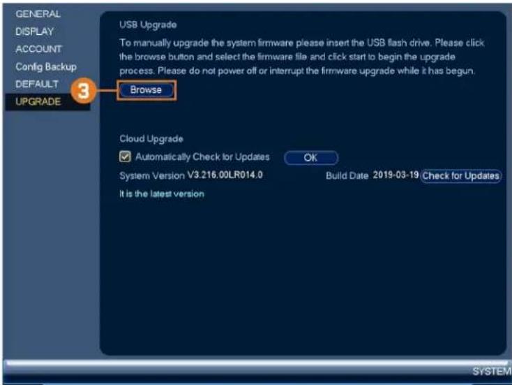
text_image
GENERAL DISPLAY ACCOUNT Config Backup DEFAULT UPGRADE 3 USB Upgrade To manually upgrade the system firmware please insert the USB flash drive. Please click the browse button and select the firmware file and click start to begin the upgrade process. Please do not power off or interrupt the firmware upgrade while it has begun. Browse Cloud Upgrade ✓ Automatically Check for Updates OK System Version V3.216.00LR014.0 Build Date 2019-03-19 Check for Updates It is the latest version- Click Browse.
- Click on the .bin firmware file for your recorder.
- Click Start.
16.4.21 Automatic Firmware Upgrades
Firmware upgrades provide enhanced functionality. The system will automatically check for fir ware upgrades if it is connected to the Internet.
To configure automatic firmware upgrade:
- From the Live View display, right-click to open the Quick Menu, then click Main Menu

- Click 📄, then click SYSTEM. Click the UPGRADE tab on the side panel.
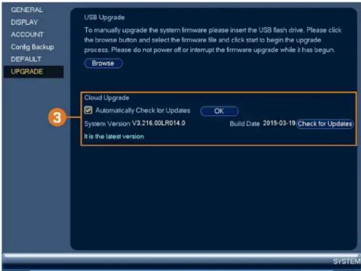
text_image
GENERAL DISPLAY ACCOUNT Config Backup DEFAULT UPGRADE USB Upgrade To manually upgrade the system firmware please insert the USB flash drive. Please click the browse button and select the firmware file and click start to begin the upgrade process. Please do not power off or interrupt the firmware upgrade while it has begun. Browse Cloud Upgrade ✓ Automatically Check for Updates OK System Version V3.216.00LR014.0 Build Date 2019-03-19 Check for Updates It is the latest version- Ensure Automatically Check for Updates is checked. If it was previously unchecked, click OK to save changes.
- Click Check for Updates to check for a newer firmware version.
- If a newer version is found, click Upgrade Now to upgrade the system.
16.5 Shutdown
Shut down, restart, or log out of the system.
To access the shutdown menu:
-
From the Live View display, right-click to open the Quick Menu, then click Main Menu
-
Click 📄, then click SHUTDOWN.
-
Select one of the following:

text_image
SHUTDOWN Shut down Logout Restart- Logout: Log out the account that is currently active.
- Shutdown: Power off the system.
- Restart: Power off the system, then restart.
Connecting Remotely using the Lorex Home Mobile App
You can connect to your security system over the Internet using our free Lorex Home app and Android devices. Securely connect to your system from anywhere with no recurring fees live viewing.

natural_image
Simple house icon inside a diamond shape, no text or symbols present

text_image
Mobile phone screenshot showing a customer service interaction with a smartphone displaying a photo and a tablet displaying a service counter scene.The Lorex Home app allows you to:
• View live video from cameras
- Play back recorded video from the hard drive
- Manually record video clips or take a snapshot of live video
- Activate deterrence features including warning lights and sirens*
- Set preferences for push notifications, informing you of motion detection and other system events
For full setup instructions and advanced support for the app, click here to open the Lorex Home instruction manual.
* On supporting devices.
Smart Home & Voice Assistance18
The recorder is compatible with third-party smart home solutions, including Amazon Alexa® Google Assistant®. You can use these services to take your security experience to the next with smart home options that make accessing your system even easier.
For compatibility information, as well as full instructions on setup and use, visit lorex.com/SmartHome.
Google and Google Home are trademarks of Google LLC.
Amazon, Alexa and all related logos are trademarks of Amazon.com, Inc. or its affiliates.
Pan/Tilt/Zoom (PTZ) Cameras19
Pan/Tilt/Zoom (PTZ) cameras are specialty cameras that move according to commands given the recorder. You can move PTZ cameras manually using the recorder's on-screen display, or ate preset locations and patterns for the camera to follow automatically.
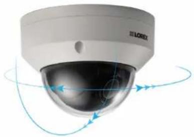
natural_image
Exterior view of a modern security camera with visible lens and control buttons (no text or symbols)19.1 Connecting PTZ Cameras to the Recorder
Lorex HD PTZ cameras connect to your recorder just like any other camera with no need special wiring — these cameras can accept PTZ commands directly through the Ethernet cab

CAUTION
When the PTZ camera powers on, it will perform an initial diagnostics check. The camera will move around this process, so ensure the camera module is not resting against another object or surface.
To connect Lorex PTZ cameras:
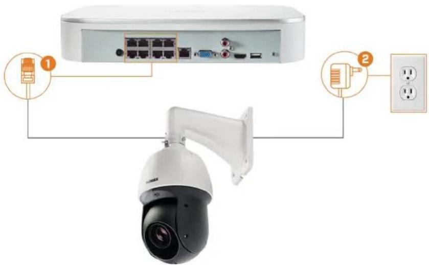
text_image
Diagram showing security camera with labeled components including a switch, network ports, and power outlet-
Connect the Ethernet cable to one of the video inputs on the recorder.
-
(OPTIONAL) Connect the PTZ camera's power adapter to a power outlet.

CAUTION
Most PTZ cameras have a higher power requirement than fixed cameras. If you are planning to connect than one PTZ camera to the system, check the power requirement in your PTZ camera's documentation to sure you remain within the total PoE power output of the recorder (80W). Connecting the included power adapter to your PTZ camera as shown above will force it to draw power from the wall outlet rather than recorder's PoE switch.
19.2 Basic PTZ Controls
Controlling PTZ cameras.

NOTE
Ensure you have completed initial setup of your PTZ camera in order to control the camera using the record 19.1 Connecting PTZ Cameras to the Recorder for more details.
To access the PTZ controls:
- Open the Live View screen for your PTZ camera in single-channel view (fullscreen). Righ click to open the Quick Menu, then click Pan/Tilt/Zoom.
• Right-click again to close PTZ controls.
To use the PTZ controls:

text_image
2 SIT Speed 5 Zoom + Focus + Iris + 1 3 4 5- Navigation Controls: Click the directional arrows to move the PTZ camera manually.
- Zoom-to-Area: Click, then click-and-drag to draw a box on the camera image. The PTZ era will zoom in to the selected area.
- Mouse Tracking: Click to enable/disable mouse tracking. When enabled, click-and-drag in the direction you would like the PTZ camera to move. The camera will follow the path mouse cursor.
4. PTZ Settings:
- Speed: The speed of PTZ camera movement. A higher value means the camera will run faster.
- Zoom: Optical zoom level. Click + to zoom in, and - to zoom out.
- Focus: Manually control focus level. Click + to focus on objects further from the camera, or - to focus on objects closer to the camera.
-
Iris: Controls the amount of light coming through the lens. Click + to allow more light, or - for less.
-
Advanced: Expand to show advanced options. For a full overview, see 19.3 Advanced PTZ Controls, page 100.
19.3 Advanced PTZ Controls
Using advanced options for PTZ cameras, including presets, tours, patterns, etc.

NOTE
Ensure you have completed initial setup of your PTZ camera in order to control the camera using the record 19.1 Connecting PTZ Cameras to the Recorder for more details.
To access the advanced PTZ controls:
- Open the Live View screen for your PTZ camera in single-channel view (fullscreen). Righ click to open the Quick Menu, then click Pan/Tilt/Zoom.
- Click the arrow on the far-right side of the PTZ control panel to access advanced option:
• Right-click again to close PTZ controls.
To use advanced PTZ controls:

NOTE
Depending on your PTZ camera model, some of the features in the advanced menu may not be supported. I your camera documentation to confirm which features are supported by your camera.

text_image
1 No. 1 2 3 4 5 6 7 8 9 10 11- No.: Enter the ID number for a preset, tour, or pattern you want to activate.
- Preset: Move the camera to the preset number specified in the No. field. For instructions on setting up preset locations, see 19.4 Presets, page 101.
- AutoPan: Set the camera to rotate 180^ back and forth.
- Tour: Perform the tour number specified in the No. field. For instructions on creating a tour, see 19.5 Tours, page 102.
- Flip: Rotate the camera 180° from its current position.
- Pattern: Perform the pattern number specified in the No. field. For instructions on creating a pattern, see 19.6 Patterns, page 102.
- Reset: Move the camera to the home position.
- AutoScan: Move the camera between a predetermined left and right point. For instructions creating an autoscan, see 19.7 AutoScan, page 102.
- Configuration: Click to open the configuration menu, where you can configure presets, to patterns and autoscans.
- OSD Menu: Click to open the camera's OSD menu. This may not be supported on all models.
- Auxiliary Settings: Not supported.
19.4 Presets
Presets will save a camera position for quick retrieval.
To add preset locations:
- From the Live View display of your PTZ camera, right-click to open the Quick Menu, click Pan/Tilt/Zoom.
- The PTZ controls open. Click to open advanced PTZ controls, then click .
- Click the Preset tab.
- Enter the number of the preset you want to create under Preset.
- Move the camera to the desired position and click Set.
To go to a preset location:
- Under No., select the number of the preset you want to go to, then click
19.5 Tours
Tours will cycle through a set of presets.
To add tours:
- From the Live View display of your PTZ camera, right-click to open the Quick Menu, click Pan/Tilt/Zoom.
- The PTZ controls open. Click to open advanced PTZ controls, then click.
- Click the Tour tab.
- Under Patrol No., enter the number of the tour you want to create.
- Under Preset, select a preset you want to add to the tour.
- Click Add Preset.
- Repeat steps 5 & 6 to add additional presets to the tour.
To run a tour:
- Under No., select the number of the tour you want to go to, then click
19.6 Patterns
Patterns automatically move the camera according to manually-entered movements.
To add patterns:
- From the Live View display of your PTZ camera, right-click to open the Quick Menu, click Pan/Tilt/Zoom.
- The PTZ controls open. Click to open advanced PTZ controls, then click .
- Click the Pattern tab.
- Under Pattern, enter the number of the pattern you want to create.
- Move the camera to the desired starting position, then click Start.
- Using the on-screen controls, move the camera in any pattern you wish. When finished, End.
To run a pattern:
- Under No., select the number of the pattern you want to go to, then click
19.7 AutoScan
An autoscan automatically cycles between a left and right point.
To configure autoscan:
- From the Live View display of your PTZ camera, right-click to open the Quick Menu, click Pan/Tilt/Zoom.
- The PTZ controls open. Click to open advanced PTZ controls, then click.
- Click the Border tab.
- Move the camera into the desired left position and click Left.
- Move the camera into the desired right position and click Right.
To run autoscan:
- Click

Connecting Audio Devices20
The system supports Lorex HD audio cameras, which transmit audio through the same network cable used for video connection and powering the camera. The system can also record one channel using the AUDIO IN port on the rear panel. You must have a self-powered microp or an audio camera with an RCA-type audio connection to use this port.
| NOTE |
| Use of an external microphone allows you to record audio on Channel 1 of the system. It cannot be moved to a different channel. |
The second RCA-type connector on the back panel is the AUDIO OUT port, which can be to connect a self-powered speaker that will play audio from the system (requires audio-capab camera or self-power microphone).
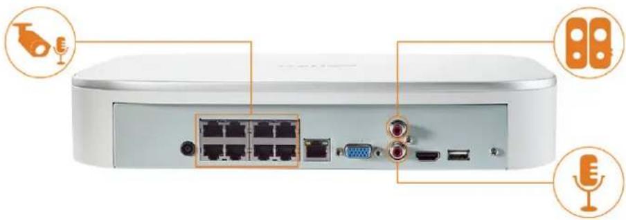
natural_image
Front view of a white electronic device rear panel with labeled ports and connectors (no text or symbols visible)To enable audio recording:
text_image
CAUTION Audio recording and / or use of listen-in audio without consent is illegal in certain jurisdictions. L assumes no liability for use of its products that does not conform with local laws.-
From the Live View display, right-click to open the Quick Menu, then click Main Menu
-
Click 🎨, then click RECORDING. Click the Recording tab on the top panel.

text_image
RECORDING Recording Snapshot Overlay Channel 1 Type Continuous Sub Stream1 Compression H.265 H.264H Super H.264/5 Off Resolution (4K)3840x215 (D1)704x480 Frame Rate(FPS) 15 15 Bit Rate Type CBR CBR Bit Rate(Kbps) 4096 256 Reference Bit Rate 1024-4096Kbps 256-1280Kbps Audio/Video ✓ ✓ ✓ Audio Encode G.711A AAC Sampling Rate 8000 8300 Default Copy Refresh OK Cancel Apply RECORDING-
Select the channel where the audio camera is connected.
-
Select the type of recording to enable audio for. If you wish to record audio at all time you configure both Continuous and MD (Motion Detection) recording.
-
Configure the following:
• Audio/Video: Ensure all boxes are checked.
• Audio Encode: Select an audio codec (G711a or AAC recommended).

CAUTION
In order to use voice commands with your security system, you must choose AAC encoding for the Sub Stream. For more details on using voice commands with your security system, see 18 Smart Home & Voice Assistance, page 98.
- Sampling Rate: Select an audio sampling rate (8000 recommended).
- Click Apply.
Replacing the Hard Drive21
The system comes with a pre-installed 3.5" SATA hard drive. You can replace the hard dri one up to a maximum size of 10TB.
21.1 Removing the Hard Drive

CAUTION
Make sure that the system is OFF and the power adapter is disconnected before removing/installing a hard d
To remove the hard drive:
-
Power off the system, and unplug all cabling from the system.
-
Turn the recorder over. Remove the bottom panel screws (6×).

natural_image
Top-down view of a gray electronic device with multiple screw holes and mounting points (no visible text or symbols)- Turn the recorder over carefully, then remove the top panel.

CAUTION
The wiring to the front panel button and USB port runs along the top panel of the recorder. the top panel, rest it carefully beside the bottom panel as shown below.
When ser
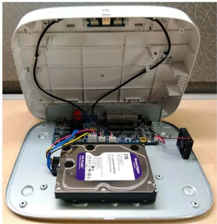
natural_image
Interior view of a computer case showing an open chassis with internal components and wiring, no visible text or symbols.- Remove the power and SATA cables from the hard drive.

natural_image
Close-up of a white and blue hard disk drive with visible circuit board and wiring, no readable text or symbols on the device itself.- Carefully pick up the hard drive to lift the bottom panel, being mindful of the sharp ed the bottom panel. Remove the hard drive screws (4×) from the bottom panel. Hold onto hard drive so it remains in place when all screws have been removed.

natural_image
Hand placing a component with multiple screw holes on a gray electronic device (no text or symbols visible)- If you are not immediately going to install a new hard drive, replace the top panel and bottom panel screws.
21.2 Installing a New Hard Drive
| CAUTION |
| Make sure that the system is OFF and the power adapter is disconnected before removing/installing a hard d |
To install a new hard drive:
- Insert the 2 hard drive screws closest to the SATA and power ports on the hard drive en them half way.

natural_image
Internal view of a hard disk drive showing internal circuit board, drive casing, and cable (no text or symbols visible)-
Power off the system, and unplug all cabling from the system.
-
Turn the recorder over. Remove the bottom panel screws (6×).
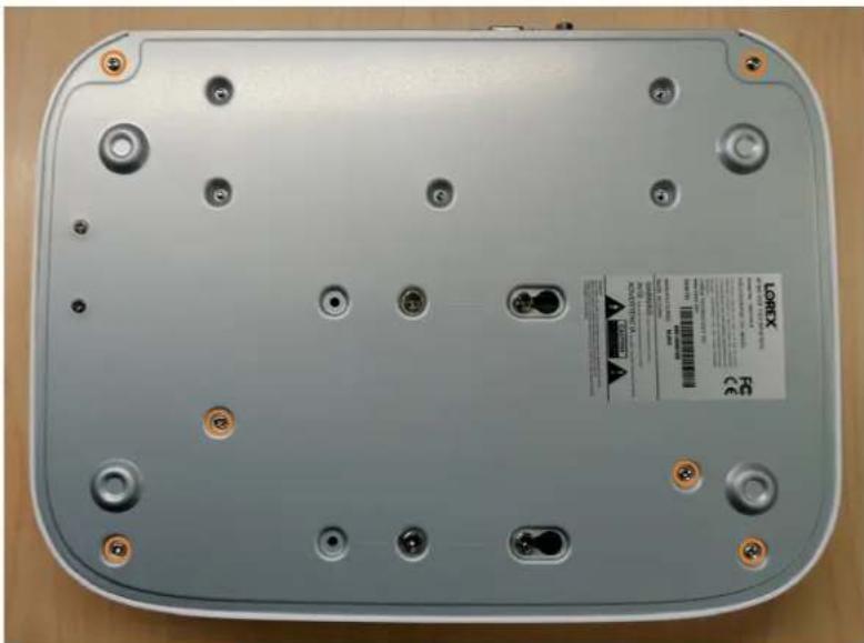
natural_image
Top-down view of a gray electronic device with multiple screw holes and mounting points (no visible text or symbols)- Turn the recorder over carefully, then remove the top panel.

CAUTION
The wiring to the front panel button and USB port runs along the top panel of the recorder. the top panel, rest it carefully beside the bottom panel as shown below.
When sef

natural_image
Interior view of a computer case showing an open chassis with internal components and wiring, no visible text or symbols.- Line the 2 half-inserted hard drive screws with the 2 holes shown below.

natural_image
Interior view of a laptop with visible circuit board and wiring, no text or symbols present
natural_image
Interior view of a computer hard drive showing internal components and wiring (no visible text or symbols)- Carefully pick up the bottom panel with the hard drive, being mindful of the sharp edge the bottom panel. Slide the 2 pre-inserted screws into the locked position, then tighten the screws. Insert and tighten the 2 remaining hard drive screws.
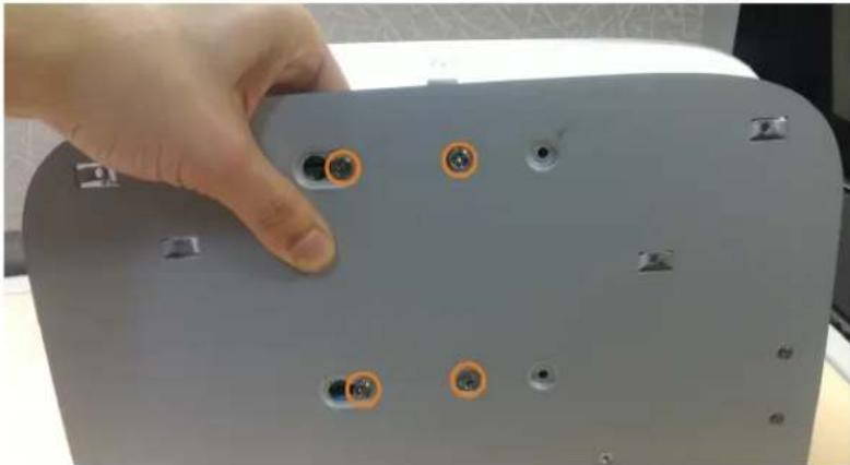
natural_image
Hand holding a gray electronic device with multiple screw holes and mounting screws (no visible text or symbols)- Connect the power and SATA cables to the hard drive.
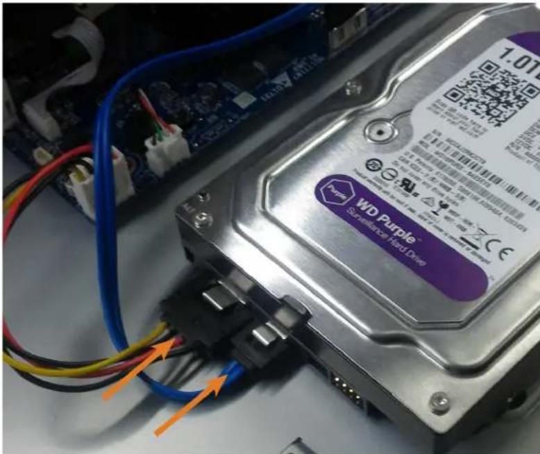
text_image
1.01 WD Purple Supervision for Hard Drive- Replace the top panel and the 6 bottom panel screws.
DDNS Setup (Advanced)22
Setting up DDNS connectivity allows you to view your recorder from any computer or com mobile device with Internet access.
NOTE
The primary connectivity option for the recorder uses the Lorex Home app to connect to your system over Internet without the need for port forwarding or DDNS registration.
- For instructions on using the Lorex Home app for mobile devices, see 17 Connecting Remotely using the Lorex Home Mobile App, page 97.
22.1 STEP 1: Port Forwarding
If you are using DDNS, you must port forward the HTTP and Client Ports (default: 80 and
35000) on your router to your recorder's IP address before you can remotely connect to yo system:
- Manually port forward the required ports on your router to your recorder's IP address by lowing your router manufacturer's instructions. For more information on port forwarding, so the reference guides on lorex.com.
22.2 STEP 2: Create a Lorex Account
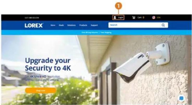
text_image
LOREX® Store Deal Solutions Products Support Search Free Moving Resume | Free Mapping Upgrade your Security to 4K Get 4K Ultra HD resolution without breaking the Bank Send Home- Visit lorex.com and click Login at the top of the page.

text_image
Login Please select one of the options listed below, as a guest user you will have an opportunity to create an account at the end if one does not exist for you. I Have a LOREX Account Create an Account Tox Smith licomini@email.com Email: lorex@mail.com Email: lorex@mail.com Email: lorex@mail.com Email: lorex@mail.com Email: lorex@mail.com Email: lorex@mail.com Email: lorex@mail.com Email: lorex@mail.com Email: lorex@mail.com Email: lorex@mail.com Email: lorex@mail.com Email: lorex@mail.mal Email: lorex@mail.mal Email: lorex@mail.mal Email: lorex@mail.mal Email: lorex@mail.mal Email: lorex@mail.mal Email: lorex@mail.mal Email: lorex@mail.mal Email: lorex@mail.mal Email: lorex@mail.mal Email: lorex@mail.mol Email: lorex@mail.mol Email: lorex@mail.mol Email: lorex@mail.mol Email: lorex@mail.mol Email: lorex@mail.mol Email: lorex@mail.mol Email: lorex@mail.mol Email: lorex@mail.mol Email: lorex@mail.mol Email: lorex@mail.mal Email: lorex@mail.mal Email: lorex@mail.mal Email: lorex@mail.mal Email: lorex@mail.mal Email: lorex@mail.mal Email: lorex@mail.mal Email: lorex@mail.mal Email: lorex@mail.mal Email: lorex@mail.mul Email: lorex@mail.mul Email: lorex@mail.mul Email: lorex@mail.mul Email: lorex@mail.mul Email: lorex@mail.mul Email: lorex@mail.mul Email: lorex@mail.mul Email: lorex@mail.mul Email: lorex@mail.mul Email: lorex@mail.mal Email: lorex@mail.mal Email: lorex@mail.mal Email: lorex@mail.mal Email: lorex@mail.mal Email: lorex@mail.mal Email: lorex@mail.mal Email: lorex@mail.mal Email: lorex@mail.mal Email: lorex@mail.mall Email: lorex@mail.mall Email: lorex@mail.mall Email: lorex@mail.mall Email: lorex@mail.mall Email: lorex@mail.mall Email: lorex@mail.mall Email: lorex@mail.mall Email: lorex@mail.mall Email: lorex@mail.mall Email: lorex@mail.mal Email: lorex@mail.mal Email: lorex@mail.mal Email: lorex@mail.mal Email: lorex@mail.mal Email: lorex@mail.mal Email: lorex@mail.mal Email: lorex@mail.mal Email: lorex@mail.mal Email: lorex@mail.mtal Email: lorex@mail.mtal Email: lorex@mail.mtal Email: lorex@mail.mtal Email: lorex@mail.mtal Email: lorex@mail.mtal Email: lorex@mail.mtal Email: lorex@mail.mtal Email: lorex@mail.mtal- Select Create an Account.

NOTE
If you have already set up an account, select I Have a LOREX Account and log in. Proceed directly to , page
- Enter basic information for account setup.
- Click Create an Account.
22.3 STEP 3: Activate Your Warranty
Activate the manufacturer's warranty on your recorder.
To activate your product warranty:

text_image
My Warranties Activating your product warranty is the most effective way to keep track of your product models and purchase dates and provides you with access to Technical Support and Customer Service assistance. Please click here to read more about your warranty. You can activate a new warranty registration by clicking on the "Activate Warranty" button and completing the form, and you can review a previously activated warranties below. Tip: It is a good idea to keep a copy of your receipt in an easy to find location. If you require warranty repair or assistance, our Customer Service team will need a copy of the receipt as proof of purchase. Activate Warranty Activate a New Warranty $9414018 $4522279 Used Bit of Sale (except Note 100) Share Buy On the store Cancel Save Warranty- From your Lorex account, click the WARRANTIES tab.
- Click Activate Warranty.
- Enter your product information (attaching bill of sale optional).
- Click Save Warranty.
Once submitted, your warranty information will be summarized under My Warranties.
22.4 STEP 4: Sign Up for a DDNS Account
Activate the manufacturer's warranty on your recorder.
To sign up for a DDNS account:
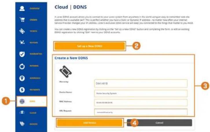
text_image
Cloud | DDNS A Lower DDNS account allows you to connect to your Lower system from anywhere in the world using an easy-to-remember web site address that is available 24/7. This is perfect whether you have a Static or Dynamic IP address - no matter how often your Internet Service Provider changes your IP address. Lower's exclusive DDNS service will keep you connected to the things that matter to you moist. You can create a new DDNS registration by clicking on the "Set Up a New DDNS" button and completing the form, or edit an existing DDNS registration by clicking "Add" next to your DDNS accounts. Set up a New DDNS Create a New DDNS Maintenance: O841.A61B Device Name: Home Security Systems MAC Address: H0-DA-00-00-00-00 URL Request: www.dsn.com/ Add Device Cancel- From your Lorex account, click the DDNS tab.
- Click Set up a New DDNS.
- Select your recorder warranty from the dropdown next to Warranty. Enter the rest of your product information.
| NOTE |
| ·The Device Name can be any name of your choice (for example, "Store Security System"). ·You can find your recorder's MAC Address in the system information window on the recorder. From the Live View display, right-click and click Info, click the Navigation Bar. |
- Click Add Device.
Once submitted, your DDNS account information will be summarized under My DDNS Dces. Make a note of your DDNS URL, Username and Password, as they will be needed to complete DDNS setup.
22.5 STEP 5: Enable DDNS on the Recorder
Enter your DDNS information into the menu of your recorder. You can find the information enclosed below on your My Lorex account, or on the confirmation email sent to you after re; for DDNS service.
To configure DDNS in the recorder:
-
From the Live View display, right-click to open the Quick Menu, then click Main Menu
-
Click 📧, then click NETWORK. Click the DDNS tab on the side panel.
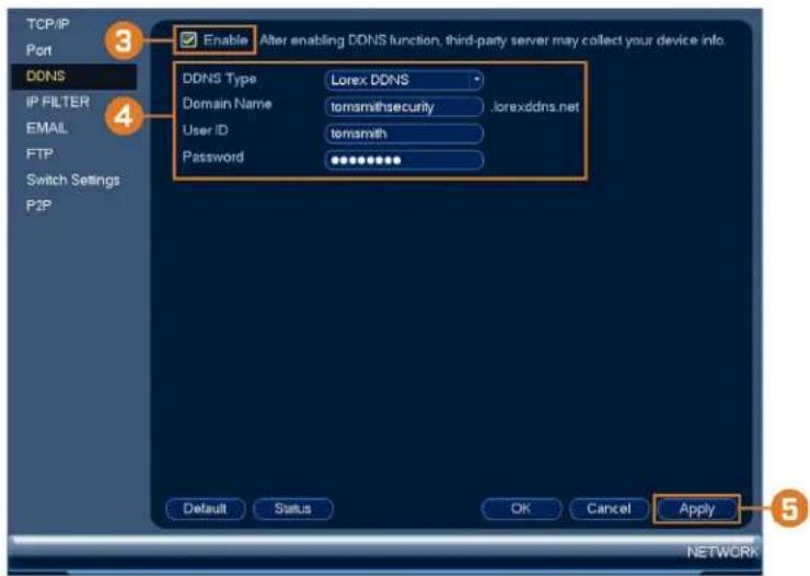
text_image
TCP/IP Port DDNS IP FILTER EMAIL FTP Switch Settings P2P Enable After enabling DDNS function, third-party server may collect your device info. DDNS Type Lorex DDNS Domain Name tomsmithsecurity .jorexdns.net User ID tomsmith Password ****** Default Status OK Cancel Apply 5 NETWORK-
Check to enable DDNS connectivity.
-
Configure the following:
• DDNS Type: Select Lorex DDNS.
- Domain Name: Enter the first part of the DDNS domain that you requested during se
- User ID: Enter the username provided in the DDNS confirmation email.
- Password: Enter the password provided in the DDNS confirmation email.
- Click Apply.
You will now be able to access your system remotely using DDNS. Enter the full domain name into a web browser (e.g., http://www.tomsmithsecurity.lorexddns.net) and login using the provided credentials.
| NOTE |
| If your system uses an HTTP port other than 80, you will need to add a colon to the end of y name and enter the port number (e.g., http://www.lomsmithsecurity.lorexddns.net:81) |
Troubleshooting23
When a malfunction occurs, it may not be serious and can be corrected easily. The following scribes the most common problems and solutions. Please refer to the following before calling ex technical support:
| Error Possible Causes Solutions | ||
| System is not receiving power or is not powering up. | Cable from power adapter is loose or is unplugged. | Confirm that all cables are connected correctly.Confirm that the power adapter is securely connected to the back of the unit. |
| Cables are connected, but system is not receiving sufficient power. | Confirm that the system is powered on (LED indicators on the front should be ON).If the unit is connected through a power bar or surge protector, try bypassing the bar and connecting the power directly to the wall outlet.Confirm that there is power at the outlet:Connect the power cable to another outlet.Test the outlet with another device (such as a lamp or phone charger). | |
| Hard drive is not detected by the system. | Hard drive cables are loose or not properly connected. | Remove the housing and check that hard drive cables are firmly connected. |
| There is no hard drive in the system. | Open the housing and install compatible hard drive. Make sure to format the drive after installing. For details, see 21 Replacing the Hard Drive, page 106. | |
| Hard drive is full (0%) and unit is no longer recording. | Overwrite is not enabled. See 9.5 Configuring Hard Drive Overwrite, page 27 for full instructions on enabling hard drive overwrite. | |
| There is no picture on monitor/TV after connecting it to the system. | Monitor/TV not detected by system. | Power off the monitor/TV and system. Power on the monitor/TV, and then power on the system. |
| Input channel for system not lected on monitor/TV. | On the monitor/TV, select the input channel the system is connected to. | |
| Video cable is loose or has come disconnected. | Check the video cable connection to the system and monitor/TV. | |
| Camera is not compatible with recorder. | theVisit lorex.com/compatibility and navigate to N841 Series for a list of all compatible cameras. | |
| • Mouse not detected by system. | • Mouse cable is not firmly connected to the system.Mouse is not connected to the system. | • Firmly connect the mouse cable to one of the USB ports. |
| • System needs to be reset • Power off the system (disconnect power cable). Firmly connect a USB mouse to one of the USB ports. Reconnect the power cable to the DC 12V port on the rear panel. | ||
| • There is no picture on selected channels / camera picture is being displayed. | • Camera cables are loose or have not become disconnected. | • Check the camera video cable and connections.• Disconnect and reconnect the cable at the system and at the camera.• Try moving the camera to another channel or use another cable. |
| Camera is not compatible with recorder. | theVisit lorex.com/compatibility and navigate to N841 Series for a list of all compatible cameras. | |
| Power output of the recorder's switch is being exceeded. | Polf you have multiple PTZ cameras connected to the recorder's PoE ports, the camera power requirement may surpass the recorder's power output. Lorex PTZ cameras come with a power adapter, which you can use to power the camera instead of the recorder's PoE ports.See 19 Pan/Tilt/Zoom (PTZ) Cameras, page 99 for full instructions. | |
| • The system beeps at startup. | • The beep at startup is normal. | |
| • The system beeps during motion detection. | • Motion detection is enabled and the alarm buzzer is activated. | • See 12 Motion Detection, page 42 for instructions on configuring motion detection options.Uncheck the Buzzer option in the motion detection configuration screen. |
| • I am not receiving email notifications. | • Email notification is disabled. | • Ensure you have configured email notification. For details, see 16.4.4 Configuring Email Alerts, page 77. |
| • Send Email setting not enabled in Event menu. | • Make sure that Send Email is checked for any events you want to be notified of. | |
Technical Specifications24
24.1 General
| Video Transmission Technology |
| Channels |
24.2 Inputs/Outputs
| Video Input |
| Video Outputs |
| Audio Input |
| Audio Output |
24.3 Display
| Display Output Resolution |
| Live Display |
| Live Display Speed (Max) |
| OSD |
| System Navigation |
24.4 Recording
| Recording Resolution |
| Recording Frame Rate |
| Recording Scheduling |
| Back-up File Format |
| Video Compression |
24.5 Playback
| Simultaneous Playback |
| Playback Speed |
| Search |
24.6 Storage
| Hard Drive Bays |
| Hard Drive Capacity |
| Backup Media |
24.7 Special Features
| Smart Motion Detection |
| Smart Search |
| Third Party Integrations |
24.8 Smart Home
| Amazon Alexa |
| Google Assistant |
| Streaming Options |
24.9 Connectivity
| Mobile Viewing ^2 | Android, |
| Compatible App Lorex Ho | |
| PC/MAC Remote Viewing Yes/Lorex | |
| Email Notification Text and | |
| Network Interface | 10/100 B. |
| Network Bit Rate | 80Mbps t |
| DDNS Ycs (Opti | |
| USB Interface USB 2.0 × |
24.10 Additional Specifications
| FW Upgrade |
| Watchdog Function |
| Power Consumption |
| Supply Voltage |
| Total PoE Power Output |
| Unit Dimensions (W × D × II) |
| Unit Weight |
| Operating Temperature |
| Humidity |
Disclaimers:
- HDMI output supports 4K HD for high definition multi-channel live or recorded video viing. Image quality and resolution is dependent on the type of camera connected to the as well as TV/monitor resolution.
- Compatible with certain Lorex IP cameras only. For a list of compatible cameras please visit lorex.com/compatibility
- Controlling certain features in your security system requires a compatible smart device. Availability and performance of certain features and services are smart device dependent and not be available in all areas or networks. For compatibility, features, and instructions visit lorex.com/SmartHome
- Both firmware and software must be updated to latest version to ensure remote connectivity.
Notices25
This product has been certified and found to comply with the limits regulated by FCC, EM LVD. Therefore, it is designated to provide reasonable protection against interference and will cause interference with other appliance usage. However, it is imperative that the user follows guidelines in this manual to avoid improper usage, which may result in damage to the prod electrical shock and fire hazard injury.
25.1 FCC/IC
This equipment has been tested and found to comply with the limits for a digital device, p to Part 15 of the FCC Rules. These limits are designed to provide reasonable protection ag harmful interference in a residential or commercial installation. This equipment generates, uses, and can radiate radio frequency energy and, if not installed and used in accordance with the struction manual, may cause harmful interference to radio communications.
25.2 CE
This product and the supplied accessories are marked with "CE" and comply with the applied harmonized European standards listed under Low Voltage Directive 2006/95/EC and the EMC rective 2004/108/EC.
25.3 Modification
Any changes or modifications not expressly approved by the grantee of this device could vo user's authority to operate the device.
This product is fully compliant with the European Union Restriction of the Use of Certainous Substances in Electrical and Electronic Equipment ("RoHS") Directive (2002/95/EC). The RoHS directive prohibits the sale of electronic equipment containing certain hazardous substances such as lead, cadmium, mercury, and hexavalent chromium, PBB, and PBDE in the European Union.
25.5 ICES-003
This device meets the CAN ICES-3 (A) / NMB-3 (A) standards requirements.
Website
www.lorextechnology.com
Copyright
© 2019, Lorex Corporation
All rights reserved worldwide. Names and marks appearing herein are either registered trademarks or trademarks of Lorex Corporation and/or its subsidiaries. All other trademarks, trade names or company names referenced herein are used for identification only and are the property of their respective owners.
Legal disclaimer
As our product is subject to continuous improvement, Lorex Corporation & subsidiaries reserve the right to modify product design, specifications & prices without notice and without incurring any obligation.E&OE.