HDBT104 - Electronics Projecta - Free user manual and instructions
Find the device manual for free HDBT104 Projecta in PDF.

User questions about HDBT104 Projecta
0 question about this device. Answer the ones you know or ask your own.
Ask a new question about this device
Download the instructions for your Electronics in PDF format for free! Find your manual HDBT104 - Projecta and take your electronic device back in hand. On this page are published all the documents necessary for the use of your device. HDBT104 by Projecta.
USER MANUAL HDBT104 Projecta
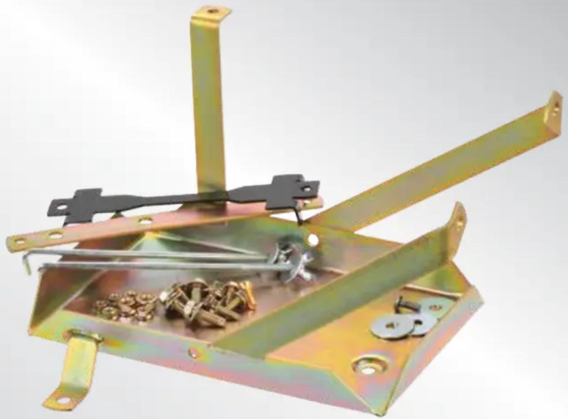
Tray Fitting Instructions to suit Auxiliary battery for Toyota 100 & 105 Series, Petrol & Diesel
Years: 1998–2007
Models: 1HDFTE 6 Cyl 4.2 TDI
All can be used as a 3rd tray for models 1HZ 6 cylinder 4.2 Diesel, 1FZFE 6 cylinder 4.5 Litre Petrol
natural_image
Metallic mechanical device with attached clamps and bolts, no visible text or symbols
natural_image
Silver SUV parked on a dirt road with desert background (no visible text or symbols)IMPORTANT SAFETY INFORMATION
Please read this instruction thoroughly before fitting the tray.
This product is recommend to be fitted by a workshop or qualified mechanical person.
WARNINGS
- Before installation, make sure that the vehicle is stationary and the wheels chocked.
- Be careful when laying wires, not to cause any electrical shorts or wire breakage.
- After installation ensure the bonnet can close without hitting the newly installed battery and battery tray.
SPECIFICATIONS
| Max Battery Size (mm) L265 x W174 x H220 |
| Max Battery Weight 21Kg |
| Recommended batteries Exide LCS 24-86, Exide Orbital, Optima D34 & Century NS70T |
| Approximate fitting time 2 hours |
| Special tools None required |
| Recommended Dual P/n: IDC25, DBC150, VSR200Battery System |
| Tray Location Engine Bay, Passenger side near firewall |
KIT INCLUDES
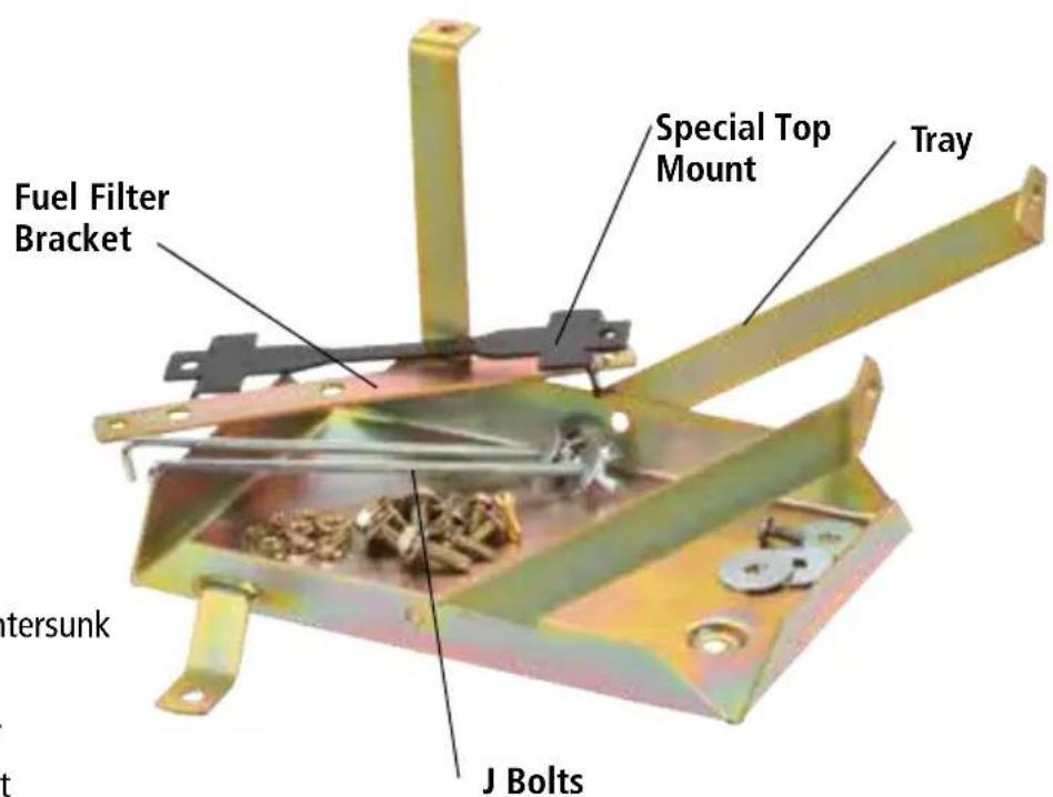
Hardware
4 x M6 Bolt
1 x M6 Nut
1 x M6 Bolt countersunk
5 x M6 Nuts
3 x Body Washer
1 x M6 Weld Bolt
2 x M8 Bolt Long
2 x M8 Bolt Short
2 x M8 Nut
FITTING INSTRUCTIONS
-
Make sure that the vehicle is stationary, the engine is switched off and cool. Disconnect the negative battery terminal from the main battery.
-
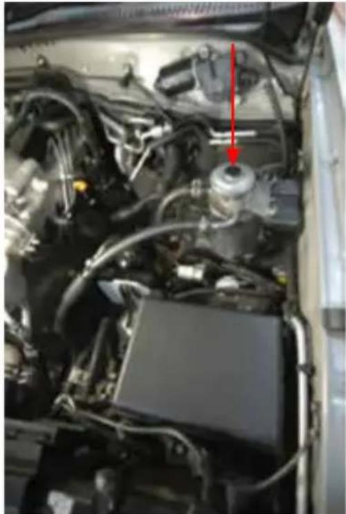
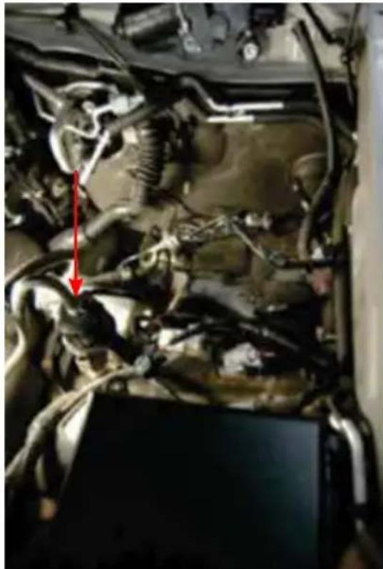
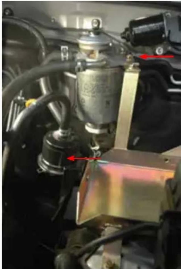
Remove fuel filter/Primer and Bracket.
natural_image
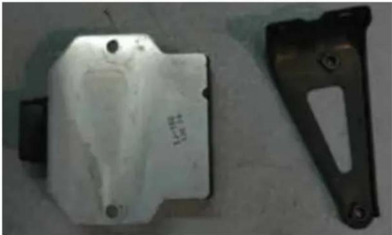
Close-up of an automotive engine bay with visible components and a red arrow pointing to a component (no text or symbols present)- Remove Computer and Bracket.
natural_image
Two metal mechanical components: a white plastic housing and a black bracket with cutouts (no visible text or symbols)- Remove Small Black fuel filter.
natural_image
Close-up of an automotive engine bay with visible hoses and a red arrow pointing to a component (no text or symbols)-
Remove all wiring on inner guard and re-run around where tray will sit.
-
Unbolt fuel line bracket from inner guard. Note the nut is under the wheel arch.
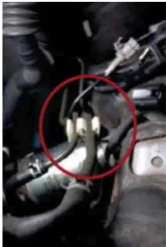
natural_image
Close-up of an engine component with a red circle highlighting a specific part (no visible text or symbols)- Mark on the rear arm of the tray where the computer is going and drill M6 holes.
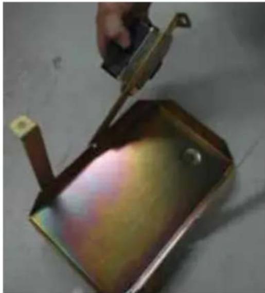
natural_image
Close-up of a metal container being cut with a tool, no visible text or symbols-
Bolt the computer to the tray. Using flat head M6 bolts and nuts. The flat bolt head should face the battery.
-
Place tray in position and manipulate air/con line to gain clearance on upper mount.
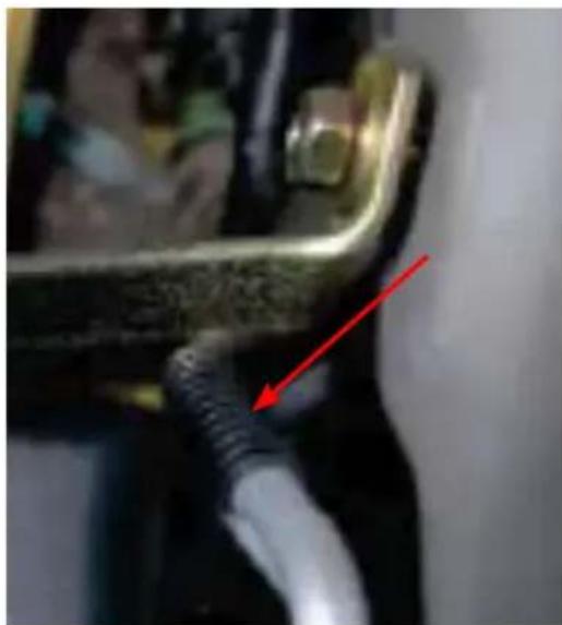
natural_image
Close-up of a mechanical component with a red arrow pointing to a cable or wire (no visible text or symbols)- Using 2 x M8 short bolts, align and bolt both upper arms to the captive nuts on the body.
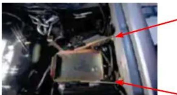
natural_image
Close-up of an engine compartment with red arrows pointing to structural components (no visible text or symbols)-
Using M6 bolts align & bolt 3 mounts in lower tray, ensuring to use the M6 counter sunk bolts in tray mount. Hand tighten only (see image from point 10). You will need to use the nuts and washers supplied.
-
Plug computer back in and tighten all tray mounting bolts.
-
Place provided fuel filter bracket between tray and firewall and bolt to tray.
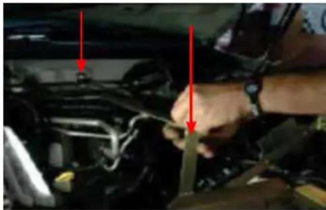
natural_image
Close-up of a person's hand adjusting a car engine compartment with red arrows pointing to the components (no visible text or symbols)-
Drill lip in firewall for bracket (wiring loom needs to be unbolted and moved so it doesn't get drilled.)
-
Bolt Fuel filter bracket using M6 bolt & nut provided.
natural_image
Close-up of a mechanical assembly with visible wiring and components, no readable text or symbols present.- Manipulate fuel lines and re-bolt filter/primer to fuel filter bracket.
- Align small black fuel filter against tray and drill hole for mounting, then mount using weld bolt to allow clearance on battery.
- Place battery into position, fit J bolts at the bottom of the tray and tighten top mount.
- Reconnect the negative battery terminal to the main starter battery or install the desired Dual Battery System. Before closing the bonnet make sure the battery and tray do not kit the bonnet.
For assistance throughout the installation procedure please call our customer service representatives on 1800 113 443.
WARRANTY STATEMENT
APPLICABLE ONLY TO PRODUCT SOLD IN AUSTRALIA
Brown & Watson International Pty Ltd of 1500 Ferntree Gully Road, Knoxfield, Vic., telephone (03) 9730 6000, fax (03) 9730 6050, warrants that all products described in its current catalogue (save and except for all bulbs and lenses whether made of glass or some other substance) will under normal use and service be free of failures in material and workmanship for a period of one (1) year (unless this period has been extended as indicated elsewhere) from the date of the original purchase by the consumer as marked on the invoice. This warranty does not cover ordinary wear and tear, abuse, alteration of products or damage caused by the consumer.
To make a warranty claim the consumer must deliver the product at their cost to the original place of purchase or to any other place which may be nominated by either BWI or the retailer from where the product was bought in order that a warranty assessment may be performed. The consumer must also deliver the original invoice evidencing the date and place of purchase together with an explanation in writing as to the nature of the claim.
In the event that the claim is determined to be for a minor failure of the product then BWI reserves the right to repair or replace it at its discretion. In the event that a major failure is determined the consumer will be entitled to a replacement or a refund as well as compensation for any other reasonably foreseeable loss or damage.
This warranty is in addition to any other rights or remedies that the consumer may have under State or Federal legislation.
IMPORTANT NOTE
Our goods come with guarantees that cannot be excluded under the Australian Consumer Law. You are entitled to a replacement or refund for a major failure and compensation for any other reasonably foreseeable loss or damage. You are also entitled to have the goods repaired or replaced if the goods fail to be of acceptable quality and the failure does not amount to a major failure.
Distributed by
AUSTRALIA
Brown & Watson International Pty Ltd
Knoxfield, Victoria 3180
Telephone (03) 9730 6000
Facsimile (03) 9730 6050
National Toll Free 1800 113 443
NEW ZEALAND
Narva New Zealand Ltd
22–24 Olive Road
PO Box 12556 Penrose
Auckland, New Zealand
Telephone (09) 525 4575
Facsimile (09) 579 1192