
DJM-2000 - DJ mixer PIONEER - Free user manual and instructions
Find the device manual for free DJM-2000 PIONEER in PDF.

| Brand | PIONEER |
| Model | DJM-2000 |
| Product Type | Professional DJ mixer |
| Dimensions (W×H×D) | 430 mm × 107.9 mm × 409 mm |
| Weight | 8.5 kg |
| Power Supply | AC 120 V, 60 Hz, 42 W (standby 0.4 W) |
| Main Functions | 5.8-inch multipoint touch panel, Frequency Mix, Sidechain Remix, INST FX (6 types), BEAT EFFECT (13 types), PRO DJ LINK, 4-channel USB audio interface, Live Sampler, MIDI |
| Sound Quality | Sampling 96 kHz, A/D converter 24-bit, D/A 32-bit |
| Inputs | PHONO (×2), CD (×4), LINE (×2), MIC (XLR/Jack), RETURN (Jack), DIGITAL IN coaxial (×4), USB (Type B), LINK (LAN ×6), CONTROL (minijack ×2) |
| Outputs | MASTER1 (XLR), MASTER2 (RCA), BOOTH (Jack), REC OUT (RCA), SEND (Jack), DIGITAL OUT coaxial, PHONES (stereo Jack), MIDI OUT (5-pin DIN) |
| Frequency Response | 20 Hz - 20 kHz (CD/LINE/MIC) |
| Signal-to-Noise Ratio | PHONO 93 dB, CD/DIGITAL/LINE 107 dB, MIC 85 dB |
| Total Harmonic Distortion | 0.004 % (LINE - MASTER1) |
| Channel EQ | HI: -26 dB to +6 dB (13 kHz), MID: -26 dB to +6 dB (1 kHz), LOW: -26 dB to +6 dB (70 Hz) |
| Microphone EQ | HI: -12 dB to +12 dB (10 kHz), LOW: -12 dB to +12 dB (100 Hz) |
| Operating Temperature | +5°C to +35°C |
| Operating Humidity | 5% to 85% (without condensation) |
| Care and Cleaning | Clean with a dry cloth. Do not use liquid or aerosol products. |
| Safety | Do not open the device. Protect from moisture and open flames. Unplug during storms or prolonged non-use. Ventilation: at least 5 cm at the back, 3 cm on sides. |
| Spare Parts and Repairability | No user-serviceable parts. Contact an authorized Pioneer service center. Serial number on rear panel. |
| Included Accessories | CD-ROM, USB cable, LAN cables (×4), power cable, warranty card, instruction manual |
Frequently Asked Questions - DJM-2000 PIONEER
User questions about DJM-2000 PIONEER
0 question about this device. Answer the ones you know or ask your own.
Ask a new question about this device
Download the instructions for your DJ mixer in PDF format for free! Find your manual DJM-2000 - PIONEER and take your electronic device back in hand. On this page are published all the documents necessary for the use of your device. DJM-2000 by PIONEER.
USER MANUAL DJM-2000 PIONEER
The Pioneer website listed above provides answers to frequently asked questions, information about software, and other up-to-date data of assistance to our customers.
Operating Instructions
Mode d'emploi
IMPORTANT

The lightning flash with arrowhead symbol, within an equilateral triangle, is intended to alert the user to the presence of uninsulated "dangerous voltage" within the product's enclosure that may be of sufficient magnitude to constitute a risk of electric shock to persons.
CAUTION
RISK OF ELECTRIC SHOCK DO NOT OPEN
CAUTION:
TO PREVENT THE RISK OF ELECTRIC SHOCK,DO NOT REMOVE COVER (OR BACK).NO USER-SERVICEABLE PARTS INSIDE.REFER SERVICING TO QUALIFIED SERVICE PERSONNEL.

The exclamation point within an equilateral triangle is intended to alert the user to the presence of important operating and maintenance (servicing) instructions in the literature accompanying the appliance.
D3-4-2-1-1_A1_En
IMPORTANT SAFETY INSTRUCTIONS
1) Read these instructions.
2) Keep these instructions.
3) Heed all warnings.
4) Follow all instructions.
5) Do not use this apparatus near water.
6) Clean only with dry cloth.
7) Do not block any ventilation openings. Install in accordance with the manufacturer's instructions.
8) Do not install near any heat sources such as radiators, heat registers, stoves, or other apparatus (including amplifiers) that produce heat.
9) Do not defeat the safety purpose of the polarized or grounding-type plug. A polarized plug has two blades with one wider than the other. A grounding type plug has two blades and a third grounding prong. The wide blade or the third prong are provided for your safety. If the provided plug does not fit into your outlet, consult an electrician for replacement of the obsolete outlet.
10) Protect the power cord from being walked on or pinched particularly at plugs, convenience receptacles, and the point where they exit from the apparatus.
11) Only use attachments/accessories specified by the manufacturer.
12) Use only with the cart, stand, tripod, bracket, or table specified by the manufacturer, or sold with the apparatus. When a cart is used, use caution when moving the cart/apparatus combination to avoid injury from tip-over.

13) Unplug this apparatus during lightning storms or when unused for long periods of time.
14) Refer all servicing to qualified service personnel. Servicing is required when the apparatus has been damaged in any way, such as power-supply cord or plug is damaged, liquid has been spilled or objects have fallen into the apparatus, the apparatus has been exposed to rain or moisture, does not operate normally, or has been dropped.
P1-4-2-2_En
NOTE:
This equipment has been tested and found to comply with the limits for a Class B digital device, pursuant to Part 15 of the FCC Rules. These limits are designed to provide reasonable protection against harmful interference in a residential installation. This equipment generates, uses, and can radiate radio frequency energy and, if not installed and used in accordance with the instructions, may cause harmful interference to radio communications. However, there is no guarantee that interference will not occur in a particular installation. If this equipment does cause harmful interference to radio or television reception, which can be determined by turning the equipment off and on, the user is encouraged to try to correct the interference by one or more of the following measures:
— Reorient or relocate the receiving antenna.
— Increase the separation between the equipment and receiver.
- Connect the equipment into an outlet on a circuit different from that to which the receiver is connected.
— Consult the dealer or an experienced radio/TV technician for help.
D8-10-1-2_A1_En
FEDERAL COMMUNICATIONS COMMISSION DECLARATION OF CONFORMITY
This device complies with part 15 of the FCC Rules. Operation is subject to the following two conditions: (1) This device may not cause harmful interference, and (2) this device must accept any interference received, including interference that may cause undesired operation.
Product Name: DJ MIXER
Model Number: DJM-2000
Responsible Party Name: PIONEER ELECTRONICS (USA) INC.
SERVICE SUPPORT DIVISION
Address: 1925 E. DOMINGUEZ ST. LONG BEACH, CA 90810-1003, U.S.A.
Phone: 1-800-421-1404
URL: http://www.pioneerelectronics.com
D8-10-4*C1_En
WARNING
This equipment is not waterproof. To prevent a fire or shock hazard, do not place any container filled with liquid near this equipment (such as a vase or flower pot) or expose it to dripping, splashing, rain or moisture.
D3-4-2-1-3_A1_En
WARNING
Before plugging in for the first time, read the following section carefully.
The voltage of the available power supply differs according to country or region. Be sure that the power supply voltage of the area where this unit will be used meets the required voltage (e.g., 230 V or 120 V) written on the rear panel.
D3-4-2-1-4*A1En
WARNING
This product equipped with a three-wire grounding (earthed) plug - a plug that has a third (grounding) pin. This plug only fits a grounding-type power outlet. If you are unable to insert the plug into an outlet, contact a licensed electrician to replace the outlet with a properly grounded one. Do not defeat the safety purpose of the grounding plug.
D3-4-2-1-6_A1_En
WARNING
To prevent a fire hazard, do not place any naked flame sources (such as a lighted candle) on the equipment.
D3-4-2-1-7a_A1_En
VENTILATION CAUTION
When installing this unit, make sure to leave space around the unit for ventilation to improve heat radiation (at least 5 cm at rear, and 3 cm at each side).
WARNING
Slots and openings in the cabinet are provided for ventilation to ensure reliable operation of the product, and to protect it from overheating. To prevent fire hazard, the openings should never be blocked or covered with items (such as newspapers, table-cloths, curtains) or by operating the equipment on thick carpet or a bed.
D3-4-2-1-7b*A1_EN
Operating Environment
Operating environment temperature and humidity: +5^ to +35^ (+41^ to +95^) ; less than 85% RH (cooling vents not blocked)
Do not install this unit in a poorly ventilated area, or in locations exposed to high humidity or direct sunlight (or strong artificial light)
D3-4-2-1-7c*A1_En
If the AC plug of this unit does not match the AC outlet you want to use, the plug must be removed and appropriate one fitted. Replacement and mounting of an AC plug on the power supply cord of this unit should be performed only by qualified service personnel. If connected to an AC outlet, the cut-off plug can cause severe electrical shock. Make sure it is properly disposed of after removal. The equipment should be disconnected by removing the mains plug from the wall socket when left unused for a long period of time (for example, when on vacation).
D3-4-2-2-1a_A1_En
CAUTION
The POWER switch on this unit will not completely shut off all power from the AC outlet. Since the power cord serves as the main disconnect device for the unit, you will need to unplug it from the AC outlet to shut down all power. Therefore, make sure the unit has been installed so that the power cord can be easily unplugged from the AC outlet in case of an accident. To avoid fire hazard, the power cord should also be unplugged from the AC outlet when left unused for a long period of time (for example, when on vacation).
D3-4-2-2-2a*_A1_En
This Class B digital apparatus complies with Canadian ICES-003.
D8-10-1-3_A1_En
Information to User
Alterations or modifications carried out without appropriate authorization may invalidate the user's right to operate the equipment.
D8-10-2_A1_En
CAUTION
This product satisfies FCC regulations when shielded cables and connectors are used to connect the unit to other equipment. To prevent electromagnetic interference with electric appliances such as radios and televisions, use shielded cables and connectors for connections.
D8-10-3a_A1_En
IMPORTANT NOTICE
THE MODEL NUMBER AND SERIAL NUMBER OF THIS EQUIPMENT ARE ON THE RIGHT SIDE. RECORD THESE NUMBERS ON YOUR ENCLOSED WARRANTY CARD AND KEEP IN A SAFE PLACE FOR FUTURE REFERENCE.
D36-AP9-1_A1_En
WARNING: Handling the cord on this product or cords associated with accessories sold with the product may expose you to chemicals listed on proposition 65 known to the State of California and other governmental entities to cause cancer and birth defect or other reproductive harm.
Wash hands after handling.
D36-P5_B1_En
POWER-CORD CAUTION
Handle the power cord by the plug. Do not pull out the plug by tugging the cord and never touch the power cord when your hands are wet as this could cause a short circuit or electric shock. Do not place the unit, a piece of furniture, etc., on the power cord, or pinch the cord. Never make a knot in the cord or tie it with other cords. The power cords should be routed such that they are not likely to be stepped on. A damaged power cord can cause a fire or give you an electrical shock. Check the power cord once in a while. When you find it damaged, ask your nearest PIONEER authorized service center or your dealer for a replacement.
S002*A1En


Want You LISTENING For A Lifetime
Dear Customer:
Selecting fine audio equipment such as the unit you've just purchased is only the start of your musical enjoyment. Now it's time to consider how you can maximize the fun and excitement your equipment offers. This manufacturer and the Electronic Industries Association's Consumer Electronics Group want you to get the most out of your equipment by playing it at a safe level. One that lets the sound come through loud and clear without annoying blaring or distortion-and, most importantly, without affecting your sensitive hearing.
Sound can be deceiving. Over time your hearing "comfort level" adapts to higher volumes of sound. So what sounds "normal" can actually be loud and harmful to your hearing. Guard against this by setting your equipment at a safe level BEFORE your hearing adapts.
To establish a safe level:
- Start your volume control at a low setting.
- Slowly increase the sound until you can hear it comfortably and clearly, and without distortion.
Once you have established a comfortable sound level:
- Set the dial and leave it there.
Taking a minute to do this now will help to prevent hearing damage or loss in the future. After all, we want you listening for a lifetime.
We Want You Listening For A Lifetime
Used wisely, your new sound equipment will provide a lifetime of fun and enjoyment. Since hearing damage from loud noise is often undetectable until it is too late, this manufacturer and the Electronic Industries Association's Consumer Electronics Group recommend you avoid prolonged exposure to excessive noise. This list of sound levels is included for your protection.
Decibel
Level Example
30 Quiet library,soft whispers
40 Living room, refrigerator, bedroom away from traffic
50 Light traffic, normal conversation, quiet office
60 Air conditioner at 20 feet, sewing machine
70 Vacuum cleaner, hair dryer, noisy restaurant
80 Average city traffic, garbage disposals, alarm clock at two feet.
THE FOLLOWING NOISES CAN BE DANGEROUS UNDER CONSTANT EXPOSURE
90 Subway, motorcycle, truck traffic, lawn mower
100 Garbage truck, chain saw, pneumatic drill
120 Rock band concert in front of speakers,
hunderclap
140 Gunshot blast, jet plane
180 Rocket launching pad
Information courtesy of the Deafness Research Foundation.


S001_A1_En
Contents
How to read this manual
The names of displays, menus, and buttons in this manual are enclosed in brackets. (e.g. [MASTER] channel, [ON/OFF], [File] menu)
01 Before start
Features 6
What's in the box. 6
12 Connections
Rear Panel 7
Connecting input terminals 8
Connecting output terminals. 8
Connecting to the control panel 9
Connecting a computer 9
About the USB audio driver software. 9
03 Operations
Control Panel. 12
Basic Operation 13
Advanced Operations 15
List of MIDI Messages 19
Types of BEAT EFFECT 23
04 Changing the settings
Setting preferences. 25
About the auto standby function. 25
05 Additional information
Troubleshooting 26
About the liquid crystal display. 27
About the exemption clauses 27
Block Diagram. 28
Specifications 29
Before start
Features
This unit is a high-performance DJ mixer designed for professional DJs, which, in addition to its high sound quality design, is equipped with a multi-touch panel and various types of interface and effect functions enabling new styles of DJ performing.
TOUCH PANEL EFFECT
This unit uses a large 5.8-inch LCD multi-touch panel. When the [FREQUENCY MIX] and [SIDECHAIN REMIX] effect functions are combined, the effect can be checked both visually and aurally, enabling intuitive control.
FREQUENCY MIX
The track frequencies are divided into seven bands and displayed graphically. Fader control on the touch panel makes it easier to grasp the details and mix two channels or swap instruments (parts).
SIDECHAIN REMIX
The sound of a specific channel can be used as the trigger to apply effects to the sound of other channels. Operation of the touch panel's pad makes it possible to process sound dynamically.
INST FX
This unit is equipped with six types of effects (NOISE, ZIP, CRUSH, JET, HPF, LPF). Effects can be obtained simply by turning the [FILTER] controls for the different channels for improvisational performances, and the desired effects can be achieved by adjusting the [PARAMETER] control.
BEAT EFFECT
The DJM series' well-received BEAT EFFECT function has been carried over and further evolved. This unit is equipped with an [EFFECT FREQUENCY] function allowing the amount of the effect applied to be adjusted by frequency range, for even greater playing freedom than before.
PRO DJ LINK
When a PRO DJ LINK-compatible Pioneer DJ player (CDJ-2000, CDJ-900 etc.), a computer on which rekordbox is installed and this unit are connected by LAN cable, the PRO DJ LINK functions below can be used. For details, see About PRO DJ LINK on page 15.
SD&USBExport
rekordboxLINKExport
LIVE SAMPLER
LINK MONITOR
STATUS INFORMATION
SOUND CARD
This unit is equipped with sound card/USB audio interface allowing up to four audio sources from one computer to be assigned to the different channels and mixed. Furthermore, the master channel output signals can be output to the computer, a great convenience for example for recording the mixed sound.
HIGH SOUND QUALITY
Measures have been taken to improve sound quality for both the digital and analog inputs and outputs. Sound processing with 96 kHz sampling, a 24-bit high sound quality A/D converter and a 32-bit high sound quality D/A converter achieves more powerful, higher grade sound.
This unit supports 48 kHz 16 bit, 48 kHz 24 bit and 44.1 kHz 16 bit USB audio signals.
What's in the box
CD-ROM
USB Cable
LAN cables x 4
Power cable
Warranty card
- Operating instructions (this document)
Connections
Be sure to turn off the power and unplug the power cord from the power outlet whenever making or changing connections.
Refer to the operating instructions for the component to be connected.
Connect the power cord after all the connections between devices have been completed.
Be sure to use the included power cord.
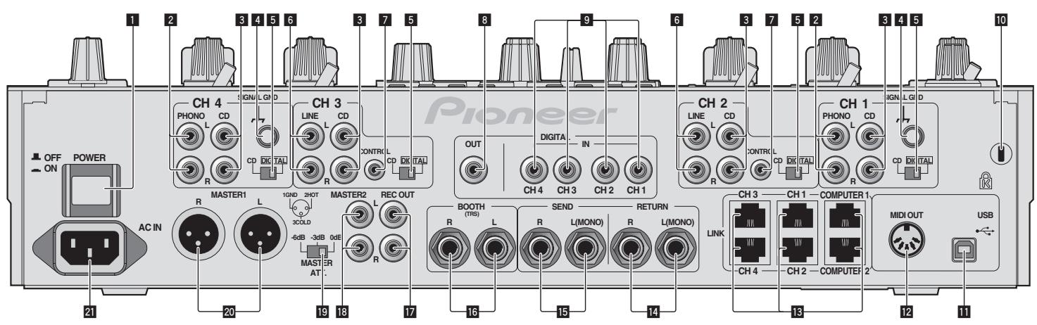
Rear Panel
1 POWER (page 13)
Turns this unit's power on and off.
2 PHONO (page 8)
Connect to a phono level (MM cartridge) output device. Do not input line level signals.
3 CD (page 8)
Connect to a DJ player or a line level output component.
4 SIGNAL GND (page 8)
Connect an analog player's ground wire here. This helps reduce noise when the analog player is connected.
5 CD, DIGITAL (page 13)
Selects the analog signal input terminals (CD) or the digital signal input terminals (DIGITAL IN).
6 LINE (page 8)
Connect to a cassette deck or a line level output component.
7 CONTROL (page 8)
Connect using a control cord (included with Pioneer DJ players).
8 DIGITAL OUT (page 8)
Outputs the master channel audio signals.
9 DIGITAL IN (page 8)
Connect these to the digital coaxial output terminals on DJ players, etc. The sound may be momentarily interrupted when the output signal sampling frequency is switched.
10 Kensington security slot
USB (page 9)
Connect to a computer.
12 MIDI OUT (page 8)
Connect this to the MIDI IN terminal on an external MIDI sequencer.
13 LINK (page 8)
Connect these to the LINK terminals on Pioneer DJ players or the LAN ports of computers on which rekordbox is installed (PRO DJ LINK).
RETURN (page 8)
Connect to the output terminal of an external effector. When the [L (MONO)] channel only is connected, the [L (MONO)] channel input is simultaneously input to the [R] channel.
15 SEND (page 8)
Connect to the input terminal of an external effector. When the [L (MONO)] channel only is connected, a monaural audio signal is output.
16 BOOTH (page 8)
Output terminals for a booth monitor, compatible with balanced or unbalanced output for a TRS connector.
17 REC OUT (page 8)
This is an output terminal for recording.
18 MASTER2 (page 8)
Connect to a power amplifier, etc.
19 MASTER ATT.
Switches the attenuation level of the sound output from the [MASTER1] and [MASTER2] terminals. Select 0 dB, -3 dB or -6 dB.
20 MASTER1 (page 8)
Connect to a power amplifier, etc.
21 AC IN
Connect to a power outlet using the included power cord. Wait until all connections between the equipment are completed before connecting the power cord.
Be sure to use the included power cord.
Connecting input terminals
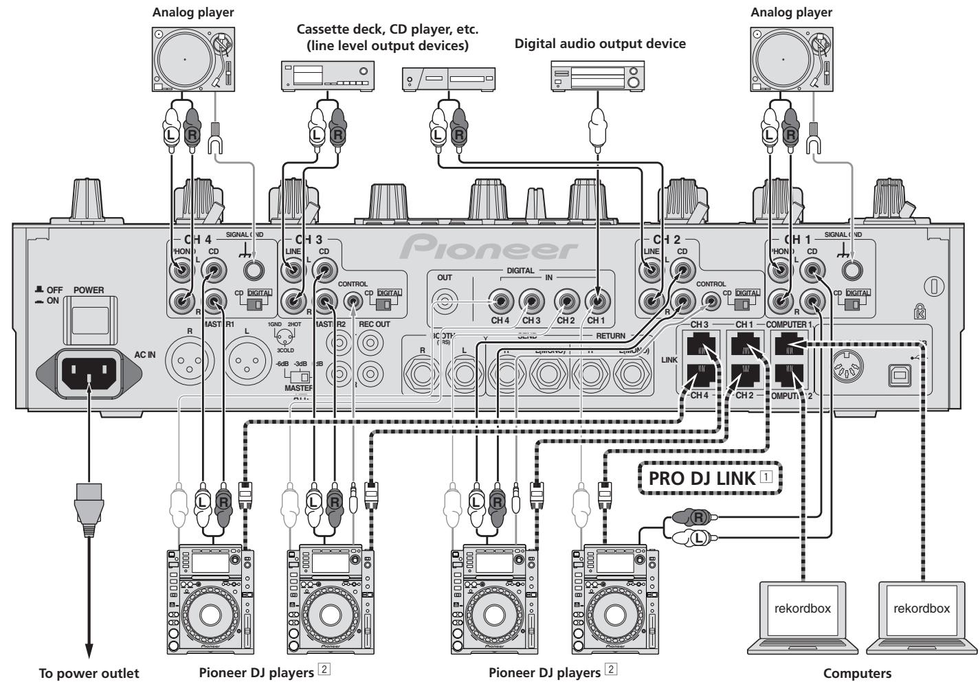
For details on PRO DJ LINK, see About PRO DJ LINK on page 15.
Use the included LAN cables to connect to Pioneer DJ players.
To use the fader start function, connect a LAN cable or control cord (page 14).
Connecting output terminals
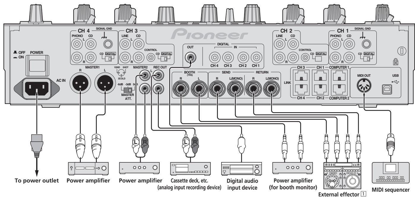
1 Also connect the external effector to the [RETURN] terminal (input terminal).
Connecting to the control panel
Connecting a computer
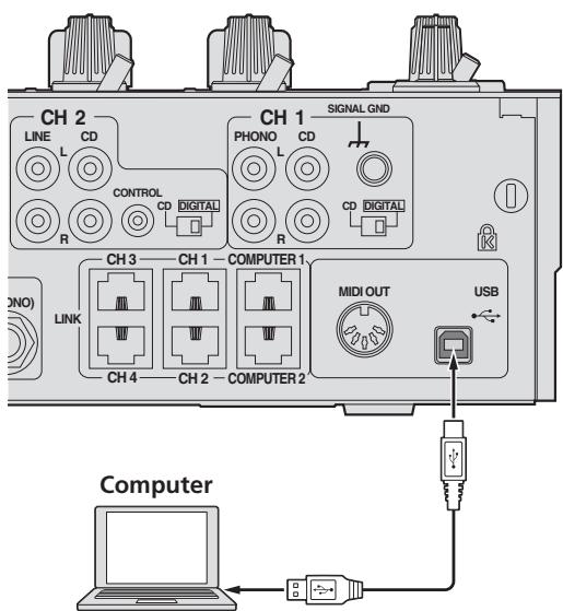
Connect with the included USB cable.
About the USB audio driver software
This driver software is a proprietary program for inputting and outputting audio signals from the computer. To use this unit connected to a computer on which a Windows or Mac OS is installed, install the driver software on the computer beforehand.
Software end user license agreement
This Software End User License Agreement ("Agreement") is between you (both the individual installing the Program and any single legal entity for which the individual is acting) ("You" or "Your") and PIONEER CORPORATION ("Pioneer"). TAKING ANY STEP TO SET UP OR INSTALL THE PROGRAM MEANS THAT YOU ACCEPT ALL OF THE TERMS OF THIS LICENSE AGREEMENT. PERMISSION TO DOWNLOAD AND/OR USE THE PROGRAM IS EXPRESSLY CONDITIONED ON YOUR FOLLOWING THESE TERMS. WRITTEN OR ELECTRONIC APPROVAL IS NOT REQUIRED TO MAKE THIS AGREEMENT VALID AND ENFORCEABLE. IF YOU DO NOT AGREE TO ALL OF THE TERMS OF THIS AGREEMENT, YOU ARE NOT AUTHORIZED TO USE THE PROGRAM AND MUST STOP INSTALLING IT OR UNINSTALL IT, AS APPLICABLE.
1 Definitions
1 "Documentation" means written documentation, specifications and help content made generally available by Pioneer to aid in installing and using the Program.
"Program" means all or any part of Pioneer's software licensed to You by Pioneer under this Agreement.
2 Program license
1 Limited License. Subject to this Agreement's restrictions, Pioneer grants to You a limited, non-exclusive, nontransferable, license (without the right to sublicense):
a To install a single copy of the Program on the hard disk drive of Your computer, to use the Program only for Your personal purpose complying with this Agreement and the Documentation ("Authorized Use");
b To use the Documentation in support of Your Authorized Use; and
c To make one copy of the Program solely for backup purposes, provided that all titles and trademark, copyright and restricted rights notices are reproduced on the copy.
2 Restrictions. You will not copy or use the Program or Documentation except as expressly permitted by this Agreement. You will not transfer, sublicense, rent, lease or lend the Program, or use it for third-party training, commercial time-sharing or service bureau use. You will not Yourself or through any third party modify, reverse engineer, disassemble or decompile the Program, except to the extent expressly permitted by applicable law, and then only after You have notified Pioneer in writing of Your intended activities. You will not use the Program on multiple processors without Pioneer's prior written consent.
Ownership. Pioneer or its licensor retains all right, title and interest in and to all patent, copyright, trademark, trade secret and other intellectual property rights in the Program and Documentation, and any derivative works thereof. You do not acquire any other rights, express or implied, beyond the limited license set forth in this Agreement.
4 No Support. Pioneer has no obligation to provide support, maintenance, upgrades, modifications or new releases for the Program or Documentation under this Agreement.
3 Warranty disclaimer
THE PROGRAM AND DOCUMENTATION ARE PROVIDED "AS IS" WITHOUT ANY REPRESENTATIONS OR WARRANTYES, AND YOU AGREE TO USE THEM AT YOUR SOLE RISK. TO THE FULlest EXTENT PERMISSIBLE BY LAW, PIONEER EXPRESSLY DISCLAIMS ALL WARRANTYES OF ANY KIND WITH RESPECT TO THE PROGRAM AND DOCUMENTATION, WHETHER EXPRESS, IMPLIED, STATUTORY, OR ARISING OUT OF COURSE OF PERFORMANCE, COURSE OF DEALING OR USAGE OF TRADE, INCLUDING ANY WARRANTYES OF MERCHANTABILITY, FITNESS FOR A PARTICULAR PURPOSE, SATISFACTORY QUALITY, ACCURACY, TITLE OR NON-INFRINGEMENT.
4 Damages and remedies for breach
You agree that any breach of this Agreement's restrictions would cause Pioneer irreparable harm for which money damages alone would be inadequate. In addition to damages and any other remedies to which Pioneer may be entitled, You agree that Pioneer may seek injunctive relief to prevent the actual, threatened or continued breach of this Agreement.
5 Termination
Pioneer may terminate this Agreement at any time upon Your breach of any provision. If this Agreement is terminated, You will stop using the Program, permanently delete it from the computer where it resides, and destroy all copies of the Program and Documentation in Your possession, confirming to Pioneer in writing that You have done so. Sections 2.2, 2.3, 2.4, 3, 4, 5 and 6 will continue in effect after this Agreement's termination.
6 General terms
1 Limitation of Liability. In no event will Pioneer or its subsidiaries be liable in connection with this Agreement or its subject matter, under any theory
of liability, for any indirect, incidental, special, consequential or punitive damages, or damages for lost profits, revenue, business, savings, data, use, or cost of substitute procurement, even if advised of the possibility of such damages or if such damages are foreseeable. In no event will Pioneer's liability for all damages exceed the amounts actually paid by You to Pioneer or its subsidiaries for the Program. The parties acknowledge that the liability limits and risk allocation in this Agreement are reflected in the Program price and are essential elements of the bargain between the parties, without which Pioneer would not have provided the Program or entered into this Agreement.
The limitations or exclusions of warranties and liability contained in this Agreement do not affect or prejudice Your statutory rights as consumer and shall apply to You only to the extent such limitations or exclusions are permitted under the laws of the jurisdiction where You are located.
Severability and Waiver. If any provision of this Agreement is held to be illegal, invalid or otherwise unenforceable, that provision will be enforced to the extent possible or, if incapable of enforcement, deemed to be severed and deleted from this Agreement, and the remainder will continue in full force and effect. The waiver by either party of any default or breach of this Agreement will not waive any other or subsequent default or breach.
4 No Assignment. You may not assign, sell, transfer, delegate or otherwise dispose of this Agreement or any rights or obligations under it, whether voluntarily or involuntarily, by operation of law or otherwise, without Pioneer's prior written consent. Any purported assignment, transfer or delegation by You will be null and void. Subject to the foregoing, this Agreement will be binding upon and will inure to the benefit of the parties and their respective successors and assigns.
5 Entire Agreement. This Agreement constitutes the entire agreement between the parties and supersedes all prior or contemporaneous agreements or representations, whether written or oral, concerning its subject matter. This Agreement may not be modified or amended without Pioneer's prior and express written consent, and no other act, document, usage or custom will be deemed to amend or modify this Agreement.
6 You agree that this Agreement shall be governed and construed by and under the laws of Japan.
Cautions on Installation
- Before installing the driver software, be sure to turn off the power of this unit and disconnect the USB cable from both this unit and your computer.
- If you connect this unit to your computer without installing the driver software first, an error may occur on your computer depending on the system environment.
- If you have discontinued the installation process in progress, step through the installation process again from the beginning according to the following procedure.
- Read Software end user license agreement carefully before installing this unit's proprietary driver software.
- Before installing the driver software, terminate all other programs running on your computer.
- The driver software is compatible with the following OSs.
Supported operating systems
| Mac OS X (10.3.9 and later) | ✓ | |
| Windows® 7 Home Premium/Professional/Ultimate | 32-bit version | ✓ |
| 64-bit version | ✓ | |
| Windows Vista® Home Basic/Home Premium/Business/Ultimate | 32-bit version | ✓ |
| 64-bit version | ✓ | |
| Windows® XP Home Edition/Professional (SP2 and later) | 32-bit version | ✓ |
Windows® XP Professional x64 edition is not supported.
- The included CD-ROM includes installation programs in the following 12 languages.
English, French, German, Italian, Dutch, Spanish, Portuguese, Russian, Simplified Chinese, Traditional Chinese, Korean, and Japanese When using operating systems in other languages, follow the instructions on the screen to select [English (English)].
Installing the driver software
Installation Procedure (Windows)
Read Cautions on Installation carefully before installing the driver software.
- To install or uninstall the driver software, you need to be authorized by the administrator of your computer. Log on as the administrator of your computer before proceeding with the installation.
1 Insert the included CD-ROM into the computer's CD drive.
The CD-ROM folder appears.
- If the CD-ROM folder is not displayed after a CD-ROM is loaded, open the CD drive from [Computer (or My Computer)] in the [Start] menu.
2 Double-click [DJM-2000_X.XXX.exe].
The driver installation screen appears.
3 When the language selection screen appears, select [English] and click [OK].
You can select one from multiple languages depending on the system environment of your computer.
4 Carefully read the Software end user license agreement and if you consent to the provisions, put a check mark in [I agree.] and click [OK].
If you do not consent to the provisions of the Software end user license agreement, click [Cancel] and stop installation.
5 Proceed with installation according to the instructions on the screen.
If [Windows Security] appears on the screen while the installation is in progress, click [Install this driver software anyway] and continue with the installation.
- When installing on Windows XP
If [Hardware Installation] appears on the screen while the installation is in progress, click [Continue Anyway] and continue with the installation. - When the installation program is completed, a completion message appears.
- When the installation of the driver software is completed, you need to reboot your computer.
Installation Procedure (Macintosh)
Read Cautions on Installation carefully before installing the driver software.
- To install or uninstall the driver software, you need to be authorized by the administrator of your computer. Have the name and password of the administrator of your computer ready in advance.
1 Insert the included CD-ROM into the computer's CD drive.
The CD-ROM folder appears.
- Double-click the CD icon on the desktop when folders are not displayed after a CD-ROM has been loaded.
2 Double-click [DJM-2000_M_X.X.X.dmg].
The [DJM-2000AudioDriver] menu screen appears.
3 Double-click [DJM-2000AudioDriver pkg].
The driver installation screen appears.
4 Check the details on the screen and click [Continue Anyway].
5 When the Software Use Agreement screen appears, select [English], carefully read the Software end user license agreement and click [Continue Anyway].
You can select one from multiple languages depending on the system environment of your computer.
6 If you consent to the provisions of the Software end user license agreement, click [Agree].
If you do not consent to the provisions of the Software end user license agreement, click [I disagree] and stop installation.
7 Proceed with installation according to the instructions on the screen.
- Click [Cancel] to cancel installation after it has started.
- When the installation of the driver software is completed, you need to reboot your computer.
Connecting the DJM-2000 and computer
1 Connect this unit to your computer via a USB cable.
This unit functions as an audio device conforming to the ASIO standards.
- When using ASIO-compatible applications, [USB 1/2], [USB 3/4], [USB 5/6] and [USB 7/8] can be used as inputs. Depending on the input/output setting, it is possible to use three of this unit's sets of inputs.
- When using DirectX-compatible applications, only [USB 1/2] can be used as the input.
- The computer's recommended operating environment depends on the DJ application. Be sure to check the recommended operating environment for the DJ application you are using.
- When another USB audio device is connected to the computer at the same time, it may not operate or be recognized normally. We recommend only connecting the computer and this unit.
- When connecting the computer and this unit, we recommend connecting directly to this unit's USB port.
2 Press [POWER].
Turn on the power of this unit.
- The message [Installing device driver software] may appear when the DJM-2000 is connected to the computer for the first time or when it is reconnected
to the computer's USB port. Wait until the [Your devices are ready for use] message appears.
-
When installing on Windows XP
-
[Can Windows connect to Windows Update to search for software?] may appear while the installation is in progress. Select [No, not this time] and click [Next] to continue with the installation.
- [What do you want the wizard to do?] may appear while the installation is in progress. Select [Install the software automatically (Recommended)] and click [Next] to continue with the installation.
- If [Windows Security] appears on the screen while the installation is in progress, click [Install this driver software anyway] and continue with the installation.
Switching the input/output setting
Use this procedure to switch the computer's input/output setting when using the driver software.
- If applications using this unit as the default audio device (DJ applications, etc.) are running, quit those applications before switching the input/output setting.
- Some time is required after the input/output setting is switched for the computer to be updated. The input/output setting cannot be switched while the computer is being updated.
- Sound may not be output if there are differences between the input/output settings on this unit and on the computer. If this happens, turn this unit's power on and reset the input/output settings with the USB cable connected.
- If the input/output setting is switched while using DirectX, the application may not recognize the driver software.
- MIDI communications are interrupted if the input/output setting is switched during MIDI communications.
Switching procedure (Windows)
Click the Windows [Start] menu>[All Programs]>[Pioneer]>[DJM-2000]>[DJM-2000 Setting Utility].
Switch the computer's input/output setting.
ASIO 4 outputs 0 inputs 16 bits DirectX 1 output 0 inputs
ASIO 3 outputs 1 input 16 bits DirectX 1 output 1 input
ASIO 3 outputs 0 inputs 24 bits DirectX 1 output 0 inputs
Switching procedure (Macintosh)
Click [Apple] [System Preferences] [Other] [DJM-2000 Settings].
Switch the computer's input/output setting.
- 8-channel output No input 16 bits
- 6-channel output 2-channel input 16 bits
- 6-channel output No input 24 bits
Adjusting the buffer size (Windows)
Use this procedure to adjust the computer's buffer size when using ASIO driver software.
Click the Windows [Start] menu>[All Programs]>[Pioneer]>[DJM-2000]>[DJM-2000 Setting Utility].
A sufficiently large buffer size decreases the chance of sound dropout (sound interruption) but increases audio signal transmission delay (latency).
- If applications using this unit as the default audio device (DJ applications, etc.) are running, quit those applications before adjusting the buffer size.
Checking the version of the driver software
Procedure for checking (Windows)
Click the Windows [Start] menu>[All Programs]>[Pioneer]>[DJM-2000]>[DJM-2000 Version Display Utility].
The [Version] screen appears.
Procedure for checking (Macintosh)
Click [Apple]>[About This Mac]>[More Info]>[Extensions]>[DJM-2000 USBAudio].
The [Version] screen appears.
Checking the latest information on the driver software
For the latest information on the driver software for exclusive use with this unit, visit our website shown below.
http://www.prodjnet.com/support/
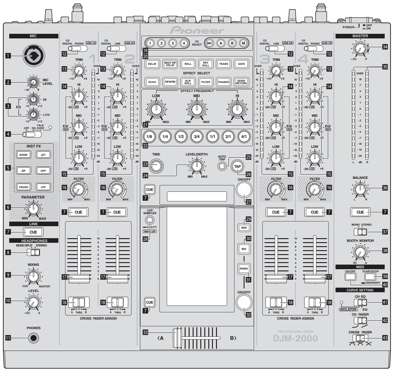
Control Panel
1 Microphone input jack (page 14)
MIC LEVEL (page 14)
EQ (HI, LOW) (page 14)
OFF, ON, TALK OVER (page 14)
5 INST FX (page 16)
6 PARAMETER (page 16)
7 CUE (page 13)
6 MONO SPLIT, STEREO (page 13)
9 MIXING (page 13)
10 LEVEL (page 13)
PHONES (page 13)
CD/DIGITAL, PHONO, LINE, USB */* (page 13)
TRIM (page 13)
14 EQ/ISO (HI, MID, LOW) (page 13)
15 Channel Level Indicator (page 13)
16 FILTER (page 16)
17 Channel Fader (page 13)
18 CROSS FADER ASSIGN (A, THRU, B) (page 13)
19 CH SELECT (page 17)
20 EFFECT SELECT (page 17)
21 EFFECT FREQUENCY (HI, MID, LOW) (page 17)
22 Beat buttons (page 17)
TIME (page 17)
24 LEVEL/DEPTH (page 17)
25 AUTO/TAP (page 17)
26 TAP (page 17)
27 ON/OFF (BEAT EFFECT) (page 17)
28 LIVE SAMPLER (UTILITY, WAKE UP) (page 16, page 25)
29 MIDI (page 17)
30 MIX (page 15)
REMUX (page 15)
32 ON/OFF (TOUCH PANEL EFFECT) (page 15)
33 Crossfader (page 13)
34 MASTER (page 13)
55 Master Level Indicator (page 13)
BALANCE (page 14)
37 MONO,STEREO (page 14)
38 BOOTH MONITOR (page 14)
START/STOP (SNAPSHOT) (page 17)
40 ON/OFF (MIDI) (page 17)
41 CH EQ (ISOLATOR, EQ) (page 13)
42 CH FADER (, page 14)
43 CROSS FADER (六, 六, 六) (page 14)
Basic Operation
Outputting sound
1 Press [POWER].
Turn on the power of this unit.
2 Switching the [CD/DIGITAL, PHONO, LINE, USB */*] switch
Select the input sources for the different channels from among the devices connected to this unit.
- [CD/DIGITAL]: Selects the DJ player connected to the [CD] terminals. To select the DJ player connected to the [DIGITAL IN] terminal, set the [CD, DIGITAL] switch on the rear panel to [DIGITAL].
- [PHONO]: Selects the analog player connected to the [PHONO] terminals.
- [LINE]: Selects the cassette deck or CD player connected to the [LINE] terminals.
- [USB /]: Selects the sound of the computer connected to the [USB] port.
3 Rotate [TRIM].
Adjusts the level of audio signals input in each channel.
The corresponding channel level indicator lights when audio signals are being properly input to that channel.
4 Set the channel fader to the inner position.
Adjusts the level of audio signals output in each channel.
5 Switch the [CROSS FADER ASSIGN (A, THRU, B)] switch.
Switches the output destination of each channel.
[A]: Assigns to [A] (left) of the crossfader.
- [B]: Assigns to [B] (right) of the crossfader.
- [THRU]: Choose this when you do not want to use the crossfader. (The signals do not pass through the crossfader.)
6 Set the crossfader.
This operation is not necessary when [CROSS FADER ASSIGN (A, THRU, B)] is set to [THRU].
7 Turn the [MASTER] control.
Audio signals are output from the [MASTER1] and [MASTER2] terminals.
The master level indicator lights.
Adjusting the sound quality
Turn the [EQ/ISO (HI, MID, LOW)] controls for the individual channels.
Refer to Specifications on page 29 for the range of sound that can be adjusted by each control.
Switching the [EQ/ISO (HI, MID, LOW)] function.
Switch the [CH EQ (ISOLATOR, EQ)] switch.
- [ISOLATOR]: The isolator function is set. The indicator lights.
- [EQ]: The equalizer function is set.
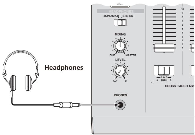
Monitoring sound with headphones
1 Connect headphones to the [PHONES] jack.
2 Press [CUE] for the channel to be monitored.
3 Switch the [MONO SPLIT, STEREO] switch.
- [MONO SPLIT]: The sound of the channel for which [CUE] is pressed is output from the headphones output's left channel, while the sound of [MASTER] is output from the right channel.
- [STEREO]: The sound of the channel for which [CUE] is pressed is output in stereo from the headphones.
4 Turn the [MIXING] control.
This adjusts the balance of the monitor volume between the sound of the channel for which [CUE] is pressed and the [MASTER] channel sound.
5 Turn the [LEVEL] control for [HEADPHONES].
Sound is output from the headphones in the channel selected by [CUE].
Monitoring is canceled when [CUE] is pressed again.
- When [LIVE SAMPLER] is turned on, [CUE] button for the TOUCH PANEL EFFECT and [CUE] button for the [LINK] cannot be pressed simultaneously.
Monitoring the sound of the computer
1 Connect headphones to the [PHONES] jack.
2 Connect a computer on which rekordbox is installed.
For instructions on connections, see Connecting input terminals on page 8.
3 Selecting the track to be monitored withrekordbox
4 Press [CUE] button for [LINK].
The track selected with rekordbox is output from the headphones.
Monitoring is canceled when [CUE] is pressed again.
- The same operation as at Monitoring sound with headphones (steps 3 to 5) can be performed.
Switching the fader curve
Select the channel fader curve characteristics.
Switch the [CH FADER ( ,) ] switch.
- [J]: The curve rises suddenly at the back side.
- []: The curve rises gradually (the sound gradually increases as the channel fader is moved away from the front side).
Select the crossfader curve characteristics.
Switch the [CROSS FADER (六, 六, 六)] switch.
- [A]: Makes a sharply increasing curve (if the crossfader is moved away from the [A] side, audio signals are immediately output from the [B] side).
- [] : Makes a curve shaped between the two curves above and below.
- [X] : Makes a gradually increasing curve (if the crossfader is moved away from the [A] side, the sound on the [B] side gradually increases, while the sound on the [A] gradually decreases).
Starting playback on a DJ player using the fader (fader start)
When connected to a Pioneer DJ player by LAN cable (included with this unit) or control cord (included with the DJ player), operations such as starting playback on the DJ player can be controlled with this unit's fader.
Connect this unit and Pioneer DJ player beforehand. For instructions on connections, see Connecting input terminals on page 8.
Start playback using the channel fader
1 Set [CROSS FADER ASSIGN (A, THRU, B)] to [THRU].
2 Set [FADER START] to [ON].
For instructions on setting, see Changing the settings on page 25.
3 Set the channel fader to the outermost position.
4 Set the cue on the DJ player.
The DJ player pauses playback at the cue point.
5 Set the channel fader to the inner position.
Playback starts on the DJ player.
- If you set the channel fader back to the original position, the player instantaneously returns to the cue point already set and pauses playback (back cue).
Start playback using the crossfader
1 Set [CROSS FADER ASSIGN (A, THRU, B)] to [A] or [B].
2 Set [FADER START] to [ON].
For instructions on setting, see Changing the settings on page 25.
3 Set the crossfader.
Set to the edge opposite the side on which the channel you want to use with the fader start function is set.
4 Set the cue on the DJ player.
The DJ player pauses playback at the cue point.
5 Set the crossfader.
Playback starts on the DJ player.
- If you set the crossfader back to the original position, the player instantaneously returns to the cue point already set and pauses playback (back cue).
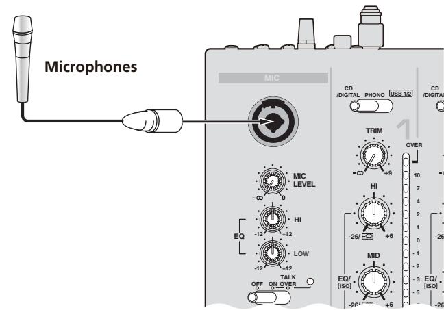
Using a microphone
1 Connect the microphone to the microphone input jack.
2 Set [OFF, ON, TALK OVER] to [ON] or [TALK OVER].
-
[ON]: The indicator lights.
— [TALK OVER]: The indicator flashes. -
When set to [TALK OVER], sound other than that from the [MIC] terminal is attenuated by 20 dB (default value) when sound of -15dB (default value) or greater is input to the microphone.
3 Turn the [MIC LEVEL] control.
This adjusts the audio level output from the [MIC] terminal.
- Pay attention that rotating to the extreme right position outputs a very loud sound.
4 Input audio signals to the microphone.
Adjusting the sound quality
Turn the [EQ (HI, LOW)] control for [MIC] channel.
Refer to Specifications on page 29 for the range of sound that can be adjusted by each control.
Switching between monaural and stereo audio
This switches the sound output from the [MASTER1], [MASTER2], [BOOTH], [REC OUT], [PHONES], [DIGITAL OUT] and [USB] terminals between monaural and stereo.
Switch the [MONO, STEREO] switch.
- [MONO]: Outputs monaural audio.
- [STEREO]: Outputs stereo audio.
Adjusting the L/R balance of audio
The left/right balance of the sound output from the [MASTER1], [MASTER2], [BOOTH], [REC OUT], [PHONES], [DIGITAL OUT] and [USB] terminals can be adjusted.
1 Set the [MONO,STEREO] switch to [STEREO].
2 Rotate [BALANCE].
The L/R balance of audio varies according to the rotation direction and position of the [BALANCE] control.
- Rotating to the rightmost position outputs only the right sound of stereo audio. Rotating to the leftmost position outputs only the left sound of stereo audio.
Audio is output from the [BOOTH] terminal
Rotate [BOOTH MONITOR].
Adjusts the level of audio signals output at the [BOOTH] terminal.
Advanced Operations
About PRO DJ LINK
When a PRO DJ LINK-compatible Pioneer DJ player (CDJ-2000, CDJ-900 etc.), a computer on which rekordbox is installed and this unit are connected by LAN cable, the PRO DJ LINK functions below can be used.
For more details on the PRO DJ LINK function, also refer to the DJ player's handling instructions and rekordbox's operating instructions.
For instructions on connections, see Connecting input terminals on page 8.
- Up to four DJ players can be connected. Up to two computers can be connected.
- Connect the DJ players to the [LINK] terminal ([CH1] to [CH4]) with the same number as the channel to which the audio cables are connected.
- Connect the computers to the [COMPUTER 1] or [COMPUTER 2] terminal.
SD & USB Export
rekindbox music files and management data on SD memory cards/USB devices connected to a CDJ-2000, CDJ-900, etc., can be transferred between DJ players.
rekordboxLINKExport
This function lets you transferrekordbox music files and management data directly, eliminating the bother of exporting the data to an SD memory card/USB device.
LIVE SAMPLER
The sound input to the [MIC] terminal or output from the [MASTER] terminals can be sampled and played on a DJ player.
LINK MONITOR
With this function, rekordbox music files stored on the computer can be quickly monitored over the headphones.
STATUS INFORMATION
This function informs the DJ players of the connected channel status (on-air status, channel number, etc.).
FREQUENCY MIX
The currently playing sound is divided into seven frequency bands that are displayed graphically. Fader control on the touch panel makes it easier to grasp the details and mix two channels or swap instruments (parts).
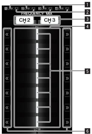
| 1 | LINK | These light when DJ players are properly connected to the [LINK] terminals. |
| 2 | FS | These light when the fader start function is turned on. |
| 3 | Channel assign buttons | These select the channels to be mixed. |
| 4 | Volume level display | The input volume level to this function is displayed in a light color, the output volume level from this function is displayed in a dark color. |
| 5 | Touch fader | These adjust the volume balance of the channels to be mixed for the separate frequency bands. |
| 6 | << >> | These move the touch fader immediately to the left or right edge. |
To mix [CH2] and [CH3]:
Prepare this unit in advance so that the sound of [CH3] is being output from the [MASTER] terminals.
1 Set the [CROSS FADER ASSIGN (A, THRU, B)] switches for [CH2] and [CH 3] to [THRU].
- Set the [CROSS FADER ASSIGN (A, THRU, B)] switches of the channels to be mixed to [THRU].
- When using the crossfader, it is recommended to set it to the center position.
2 Press [MIX].
The [FREQUENCY MIX] screen appears on the touch panel.
3 Press the channel assign buttons to select [CH2] for the left side, [CH3] for the right side.
The volume levels for the individual frequency bands of the sound playing in [CH3] are displayed on the right half of the touch panel.
4 Press all the [>>] buttons.
All the touch faders move to the right edge.
5 Press [ON/OFF].
This turns the effect on.
[ON/OFF] flashes when the effect is turned on.
6 Move the channel fader for [CH2] to the back side.
The volume levels for the individual frequency bands of the sound playing in [CH2] are displayed on the left half of the touch panel.
7 Move the touch fader to the left side.
The sound of the frequency bands whose crossfaders have been moved is mixed and output.
- The effect turns off when [ON/OFF] is pressed again.
- To switch from the [FREQUENCY MIX] to the [SIDECHAIN REMIX] mode, first press the [ON/OFF] button to turn the effect off, then press [REMX].
SIDECHAIN REMIX
When this function is used, the sound of the specified frequency band for the specified channel can be used as the trigger to apply effects to the sounds of other channels.
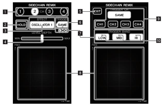
| 1 | CH | This selects the channel to which the effect is applied. |
| 2 | HOLD | This holds the effect's parameter information (the position at which the control area was touched). |
| 3 | EFFECT | This selects the type of effect. |
| 4 | LEVEL/DEPTH | Use this to adjust the amount of the effect applied. |
| 5 | EXIT | Use this to close the [TRIGGER] menu. |
| 6 | TRIGGER (SAMPLING/TRIGGER) | Use this to open the [TRIGGER] menu. |
| 7 | TRIGGER BAND | Use these to select the frequency band to be used as the trigger. |
| 8 | Control area | Use this to change the effect's parameters. |
| 9 | TRIGGER CH (SAM-PLING/TRIGGER CH) | This selects the channel to be used as the effect trigger. |
| 10 | Trigger indicators | These flash according to the automatically detected rhythm for the different frequency bands. |
To set the channel for sampling and triggering to [CH3] and mix the sampled sound with the sound of [CH2] for output:
Prepare this unit in advance so that the sound of [CH2] is being output from the [MASTER] terminals.
1 Press [REMIX].
The [SIDECHAIN REMIX] screen appears on the touch panel.
2 Press the [2] button in the [CH] section.
This selects the channel to which the effect is applied.
3 Press [EFFECT] and select [SAMPLER].
This selects the type of effect.
| Effect Name | Descriptions |
| OSCILLATOR1 - 4 | Sound is created inside this unit, mixed to the sound of the channel selected in the [CH] section, then output according to the [TRIGGER CH (SAMPLING/TRIGGER CH)] trigger. |
| SAMPLEER | The sound of the channel selected at [TRIGGER CH (SAMPLING/TRIGGER CH)] is sampled, mixed to the sound of the channel selected in the [CH] section, then output according to the [TRIGGER CH (SAMPLING/TRIGGER CH)] trigger. |
| PITCH | The pitch of the sound of the channel selected in the [CH] section is changed, mixed with the channel selected in the [CH] section, then output according to the [TRIGGER CH (SAMPLING/TRIGGER CH)] trigger. |
| GATE | The sound input at [CH] is output according to the [TRIGGER CH (SAMPLING/TRIGGER CH)] trigger. |
It is not possible to select multiple effects simultaneously.
4 Press [TRIGGER (SAMPLING/TRIGGER)].
The [TRIGGER] menu appears.
5 At [TRIGGER CH (SAMPLING/TRIGGER CH)], select [CH3].
This selects the channel to be used as the effect trigger.
- When [SAME] is pressed, the same channel as the one selected in the [CH] section is selected as the trigger.
6 At [TRIGGER BAND], press [MID] and [HI].
This selects the frequency band set as the effect trigger.
Only [LOW] (the bass sound) is selected.
7 Press [ON/OFF].
This turns the effect on.
[ON/OFF] flashes when the effect is turned on.
8 Touch the control area.
[ ] appears at the point at which the panel was touched.
The [CH3] sound at the point in the control area that was touched is sampled.
Triggered by the low frequency sound of [CH3], the sampled sound is mixed with the sound of [CH2] (which is continuing to play normally) and output from the [MASTER] terminals.
The effect changes when the position touched in the control area is changed.
- The effect turns off when [ON/OFF] is pressed again.
- The sampled sound is only valid while the control area is being touched.
- To switch from the [SIDECHAIN REMIX] to the [FREQUENCY MIX] mode, first press the [ON/OFF] button to turn the effect off, then press [MIX].
Using [HOLD]
When [HOLD] is turned on, effect's parameter information is held even if the effect is turned off. The parameter information is cleared when [HOLD] is turned off.
- The parameter information and sampled sound are cleared when the effect is switched.
LIVE SAMPLER
The sound input to the [MIC] terminal or the sound output from the [MASTER] terminals can be sampled and played on a PRO DJ LINK-compatible Pioneer DJ player.
Connect this unit and PRO DJ LINK-compatible Pioneer DJ player in advance.
For instructions on connections, see Connecting input terminals on page 8.
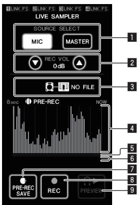
| 1 | SOURCE SELECT | Select the source to be sampled here. |
| 2 | REC VOLUME | Use these to adjust the volume for recording. The volume can be adjusted in the range -9 dB to +9 dB. |
| 3 | Status indicator | This indicates this unit's status and whether or not sampling data is available. |
| 4 | Waveform display | This displays the sound as a waveform. |
| 5 | Playing address display | This displays the sound as a bar graph. This is only displayed when previewing the sound. |
| 6 | Slider | The sound is played from the position at which the touch panel was touched. This is only displayed when previewing the sound. |
| 7 | PRE-REC SAVE | The sound is sampled from a point 8 seconds before the button was pressed. |
| 8 | REC (REC STOP) | The sound is sampled for up to 8 seconds from the point at which the button is pressed. |
| 9 | PREVIEW (STOP) | Use this to preview the sampled sound over the head-phones. |
Sampling the sound being played
1 Press [LIVE SAMPLER].
The [LIVE SAMPLER] screen appears on the touch panel.
2 Press [MIC] or [MASTER] in the [SOURCE SELECT].
This selects the channel to be sampled.
3 Press [REC (REC STOP)].
The sound of the channel selected at step 2 is sampled from the point at which [REC (REC STOP)] was pressed.
- Sampling is possible for up to 8 seconds.
- Sampling stops automatically once 8 seconds have elapsed after [REC (REC STOP)] was pressed.
4 Press [REC (REC STOP)].
Sampling stops. The sample saving screen is displayed.
Sampling the sound from the point 8 seconds before
1 Press [LIVE SAMPLER].
The [LIVE SAMPLER] screen appears on the touch panel.
2 Press [MIC] or [MASTER] in the [SOURCE SELECT].
This selects the channel to be sampled.
3 Press [PRE-REC SAVE].
The sound for the channel selected in step 2 is sampled from the point 8 seconds before [PRE-REC SAVE] was pressed.
- Sampling is possible for up to 8 seconds.
Previewing the sampled sound
1 Press the [CUE] button to the left of the touch panel.
2 Press [PREVIEW (STOP)].
The position being played is displayed at the playing address and slider displays.
- When the touch panel's slider is touched, the sampled sound is played from that position.
Playing the sampled sound on the DJ player
Use PRO DJ LINK to access this unit from the DJ player.
The sampled sound (audio file) can be loaded and played on the DJ player.
INST FX
This effect changes in association with the [FILTER] controls for the individual channels.
1 Press one of the [INST FX] buttons.
This selects the type of effect.
The button that was pressed flashes.
The same effect is set for [CH1] to [CH4].
2 Turn the [FILTER] control.
The effect is applied to the channel(s) for which the control(s) was (were) pressed.
| Effect Name | Descriptions | FILTER (parameter 1) | PARAMETER (parameter 2) |
| NOISE | White noise generated inside this unit is mixed in to the sound of the channel via the filter and output. | Sets the cut-off frequency for the filter through which the white noise passes. | Sets the volume of the white noise. |
| ZIP | Lowers the pitch of the channel's sound for output. | Sets the amount of pitch shifting for lowering the pitch. | Sets the balance between the original sound and the effect sound. |
| CRUSH | Changes the channel's sound to a crushed sound for output. | Sets the degree by which the input sound is crushed. | The further the control is turned clockwise, the more the effect is stressed. |
| JET | Adds a flanger effect for output. | Sets the flanger effect. | The further the control is turned clockwise, the more the effect is stressed. |
| HPF | Outputs the sound through the high-pass filter. | Sets the filter's cut-off frequency. | The further the control is turned clockwise, the more the effect is stressed. |
| LPF | Outputs the sound through the low-pass filter. | Sets the filter's cut-off frequency. | The further the control is turned clockwise, the more the effect is stressed. |
Adjusting the effect of the effect sound
Turn the [PARAMETER] control.
The further the control is turned clockwise, the more the effect is stressed. When turned all the way counterclockwise, the effect is minimum.
BEAT EFFECT
This function lets you instantaneously set various effects according to the tempo (BPM = Beats Per Minute) of the currently playing track.
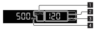
| 1 | AUTO (TAP) | [AUTO] lights when the BPM measurement mode is set to the auto mode. [TAP] lights when in the manual input mode. |
| 2 | BPM value display (3 digits) | When in the auto mode, this displays the automatically detected BPM value. When the BPM cannot be detected, the previously detected BPM value is displayed and flashes. When in the manual input mode, this displays the BPM value that was input manually. |
| 3 | BPM | This is always lit. |
| 4 | % (ms) | These light according to the units for the different effects. |
1 Press [AUTO/TAP].
Select the BPM measurement mode.
-
AUTO: The BPM is automatically measured from the input audio signal. AUTO is set when this unit's power is turned on.
TAP: The BPM is input manually by tapping [TAP]. -
The BPM measurement range when AUTO is selected is 70 to 180. Depending on the track, it may not be possible to properly measure the BPM. If not, the BPM value flashes on the display. In this case, use the [TAP] button to input the BPM manually.
2 Press one of the [CH SELECT] buttons.
This selects the channel to which the effect is applied.
[1] - [4]: The effect is applied to the sounds of channels [CH1] - [CH4].
[MIC]: The effect is applied to the sound of the [MIC] channel.
- [A], [B]: The effect is applied to the sound of the crossfader's [A] (left) or [B] (right) side.
- [M]: The effect is applied to the sound of the [MASTER] channel.
3 Press one of the [EFFECT SELECT] buttons.
This selects the type of effect.
- For the types of effects, see Types of BEAT EFFECT on page 23.
- When [SEND/RETURN] is selected, see Using the external effector below.
4 Press one of the beat buttons.
This selects the beat fraction for synchronizing the effect sound.
The effect time corresponding to the beat fraction is set automatically.
- The beat fraction can be changed by turning [TIME] while pressing the beat button.
5 Press [ON/OFF].
The effect is applied to the sound.
The effect's time parameter can be adjusted by turning the [TIME] control.
The effect's quantity parameter can be adjusted by turning the [LEVEL/DEPTH] control.
[ON/OFF] flashes when the effect is turned on.
The effect turns off when [ON/OFF] is pressed again.
Inputting the BPM manually
Tap the [TAP] button at least two times with a finger in (quarter note) beat with the currently playing sound.
The average value of the intervals at which the [TAP] button was tapped is set as the BPM.
-
When the BPM is set using the [TAP] button, the beat fraction is set to 1/1, and the time of one beat (one quarter note) is set as the effect time.
-
The BPM can be set manually by turning the [TIME] control while pressing the [TAP] button.
- The BPM can be set manually by pressing the beat button while pressing [TAP].
- The BPM can be set in units of 0.1 by turning [TIME] while pressing [TAP] and [AUTO/TAP].
Adjusting the amount of effect applied for different frequency bands
Turn the [EFFECT FREQUENCY (HI, MID, LOW)] control.
See Types of BEAT EFFECT on page 23 for the parameters of the effects that can be adjusted with the different controls.
Using the external effector
1 Connect this unit and external effector.
[SEND/RETURN] lights.
For instructions on connections, see Connecting output terminals on page 8.
2 Press one of the [CH SELECT] buttons.
This selects the channel to which the effect is applied.
3 Press [SEND/RETURN].
[SEND/RETURN] flashes.
4 Press [ON/OFF].
The sound that has passed through the external effector is output.
The effect turns off when [ON/OFF] is pressed again.
Using the MIDI function
Operating the DJ software
The DJM-2000 also outputs the operating data for the buttons and dials in MIDI format. If you connect a computer with a built-in MIDI-compatible DJ software via a USB cable, you can operate the DJ software on this unit. Install the DJ software on your computer in advance. Also, adjust audio and MIDI settings for the DJ software.
- For MIDI channel setting instructions, see Changing the settings on page 25.
1 Connect this unit's [USB] terminal to the computer.
For details about connections, see Connecting a computer on page 9.
2 Start the DJ software.
3 Press [ON/OFF] in the [MIDI] section.
Turn the MIDI function on.
Transmission of the MIDI messages begin.
- When the faders and controls are moved, messages are sent according to the positions of the faders and controls. For messages output by this unit, see List of MIDI Messages on page 19.
- MIDI messages for the positions of all the buttons, faders and controls can be sent in a single batch by pressing the [START/STOP] button for at least 2 seconds (Snapshot function).
- The MIDI timing clock (BPM information) is sent regardless of [ON/OFF].
- When [ON/OFF] in the [MIDI] section is pressed again, sending of MIDI messages stops.
Sending the MIDI start and MIDI stop messages
Press [START/STOP] in the [MIDI] section.
- The MIDI start and MIDI stop messages are sent alternately each time the [START/STOP] button is pressed, regardless of whether the MIDI function is on or off.
Using the MIDI control screens
This unit is equipped with four types of MIDI control screens. Use them according to your DJ software.
1 Press the [MIDI] button to the right of the touch panel.
The [MIDI CONTROL] screen appears on the touch panel.
2 Select a type, from [TYPE A] to [TYPE D].
This selects the type of MIDI control screen.
- When [PAGE1] or [PAGE2] is pressed, the page being displayed switches.
3 Operate the touch panel buttons or faders.
Transmission of the MIDI messages begin.
For messages output by this unit, see List of MIDI Messages on page 19.
Operating an external MIDI sequencer
This unit sends the tempo of the currently playing source (BPM information) as the MIDI timing clock. This can be used to synchronize an external MIDI sequencer with the tempo of the source.
- External MIDI sequencers not supporting MIDI timing clocks cannot be synchronized.
- External MIDI sequencers cannot be synchronized for sources for which the BPM cannot be measured stably.
- MIDI timing clocks are output even for BPM values input manually by tapping the [TAP] button with a finger. The MIDI timing clock output range is 40 BPM to 250 BPM.
1 Connect the [MIDI OUT] terminal to the external MIDI sequencer's MIDI IN terminal using a commercially available MIDI cable.
2 Set the external MIDI sequencer's sync mode to Slave.
3 Press [START/STOP].
The MIDI start message is sent.
4 Press [ON/OFF] in the [MIDI] section.
Transmission of the MIDI messages begin.
Control Panel
| Category | SW Name | SW Type | MIDI Messages | Trigger/Toggle | Notes | |||||
| MSB | LSB | |||||||||
| CH1 | TRIM | VR | Bn | 01 | dd | — | — | — | — | 0-127 |
| HI | VR | Bn | 02 | dd | — | — | — | — | 0-127 | |
| MID | VR | Bn | 03 | dd | — | — | — | — | 0-127 | |
| LOW | VR | Bn | 04 | dd | — | — | — | — | 0-127 | |
| FILTER | VR | Bn | 05 | dd | — | — | — | — | 0-127 | |
| Channel fader | VR | Bn | 11 | dd | — | — | — | — | 0-127 | |
| CROSS FADER ASSIGN | SW | Bn | 41 | dd | — | — | — | — | 0,64,127 | |
| CUE | BTN | Bn | 46 | dd | — | — | — | Trigger/Toggle | OFF=0,ON=127 | |
| CH2 | TRIM | VR | Bn | 06 | dd | — | — | — | — | 0-127 |
| HI | VR | Bn | 07 | dd | — | — | — | — | 0-127 | |
| MID | VR | Bn | 08 | dd | — | — | — | — | 0-127 | |
| LOW | VR | Bn | 09 | dd | — | — | — | — | 0-127 | |
| FILTER | VR | Bn | 0A | dd | — | — | — | — | 0-127 | |
| Channel fader | VR | Bn | 12 | dd | — | — | — | — | 0-127 | |
| CROSS FADER ASSIGN | SW | Bn | 42 | dd | — | — | — | — | 0,64,127 | |
| CUE | BTN | Bn | 47 | dd | — | — | — | Trigger/Toggle | OFF=0,ON=127 | |
| CH 3 | TRIM | VR | Bn | 0C | dd | — | — | — | — | 0-127 |
| HI | VR | Bn | 0E | dd | — | — | — | — | 0-127 | |
| MID | VR | Bn | 0F | dd | — | — | — | — | 0-127 | |
| LOW | VR | Bn | 15 | dd | — | — | — | — | 0-127 | |
| FILTER | VR | Bn | 16 | dd | — | — | — | — | 0-127 | |
| Channel fader | VR | Bn | 13 | dd | — | — | — | — | 0-127 | |
| CROSS FADER ASSIGN | SW | Bn | 43 | dd | — | — | — | — | 0,64,127 | |
| CUE | BTN | Bn | 48 | dd | — | — | — | Trigger/Toggle | OFF=0,ON=127 | |
| CH4 | TRIM | VR | Bn | 50 | dd | — | — | — | — | 0-127 |
| HI | VR | Bn | 51 | dd | — | — | — | — | 0-127 | |
| MID | VR | Bn | 5C | dd | — | — | — | — | 0-127 | |
| LOW | VR | Bn | 52 | dd | — | — | — | — | 0-127 | |
| FILTER | VR | Bn | 53 | dd | — | — | — | — | 0-127 | |
| Channel fader | VR | Bn | 14 | dd | — | — | — | — | 0-127 | |
| CROSS FADER ASSIGN | SW | Bn | 44 | dd | — | — | — | — | 0,64,127 | |
| CUE | BTN | Bn | 49 | dd | — | — | — | Trigger/Toggle | OFF=0,ON=127 | |
| Crossfader | Crossfader | VR | Bn | 0B | dd | — | — | — | — | 0-127 |
| CURVE SETTING | CH EQ (ISOLATOR, EQ) | SW | Bn | 21 | dd | — | — | — | — | 0,127 |
| CH FADER (←,→) | SW | Bn | 5E | dd | — | — | — | — | 0,127 | |
| CROSS FADER (×,×,×) | SW | Bn | 5F | dd | — | — | — | — | 0,64,127 | |
| MASTER | BALANCE | VR | Bn | 17 | dd | — | — | — | — | 0-127 |
| MASTER level | VR | Bn | 18 | dd | — | — | — | — | 0-127 | |
| CUE | BTN | Bn | 4A | dd | — | — | — | Trigger/Toggle | OFF=0,ON=127 | |
| BOOTH MONITOR | VR | Bn | 19 | dd | — | — | — | — | 0-127 | |
| CH SELECT | 1 | BTN | Bn | 22 | dd | — | — | — | Trigger/Toggle[1] | OFF=0,ON=127 |
| 2 | BTN | Bn | 23 | dd | — | — | — | Trigger/Toggle[1] | OFF=0,ON=127 | |
| 3 | BTN | Bn | 24 | dd | — | — | — | Trigger/Toggle[1] | OFF=0,ON=127 | |
| 4 | BTN | Bn | 25 | dd | — | — | — | Trigger/Toggle[1] | OFF=0,ON=127 | |
| MIC | BTN | Bn | 26 | dd | — | — | — | Trigger/Toggle[1] | OFF=0,ON=127 | |
| A | BTN | Bn | 27 | dd | — | — | — | Trigger/Toggle[1] | OFF=0,ON=127 | |
| B | BTN | Bn | 28 | dd | — | — | — | Trigger/Toggle[1] | OFF=0,ON=127 | |
| M | BTN | Bn | 29 | dd | — | — | — | Trigger/Toggle[1] | OFF=0,ON=127 | |
| BEAT EFFECT | TIME | VR | Bn | 0D | MSB | Bn | 2D | LSB | — | TIME value (half the value when FILTER or PHASER is selected for EFFECT SELECT) |
| ON/OFF | BTN | Bn | 40 | dd | — | — | — | Trigger/Toggle | OFF=0,ON=127 | |
| AUTO/TAP | BTN | Bn | 45 | dd | — | — | — | Trigger/Toggle | OFF=0,ON=127 | |
| CUE | BTN | Bn | 4B | dd | — | — | — | Trigger/Toggle | OFF=0,ON=127 | |
| TAP | BTN | Bn | 4E | dd | — | — | — | Trigger/Trigger | OFF=0,ON=127 | |
| LEVEL/DEPTH | VR | Bn | 5B | dd | — | — | — | — | 0-127 | |
| EFFECT SELECT | DELAY | BTN | Bn | 2A | dd | — | — | — | Trigger/Toggle1 | OFF=0, ON=127 |
| MULTI TAP DELAY | BTN | Bn | 2B | dd | — | — | — | Trigger/Toggle1 | OFF=0, ON=127 | |
| ROLL | BTN | Bn | 2E | dd | — | — | — | Trigger/Toggle1 | OFF=0, ON=127 | |
| REV ROLL | BTN | Bn | 2F | dd | — | — | — | Trigger/Toggle1 | OFF=0, ON=127 | |
| TRANS | BTN | Bn | 35 | dd | — | — | — | Trigger/Toggle1 | OFF=0, ON=127 | |
| GATE | BTN | Bn | 3D | dd | — | — | — | Trigger/Toggle1 | OFF=0, ON=127 | |
| ECHO | BTN | Bn | 37 | dd | — | — | — | Trigger/Toggle1 | OFF=0, ON=127 | |
| REVERB | BTN | Bn | 36 | dd | — | — | — | Trigger/Toggle1 | OFF=0, ON=127 | |
| SLIP ROLL | BTN | Bn | 3A | dd | — | — | — | Trigger/Toggle1 | OFF=0, ON=127 | |
| FILTER | BTN | Bn | 3B | dd | — | — | — | Trigger/Toggle1 | OFF=0, ON=127 | |
| PHASER | BTN | Bn | 39 | dd | — | — | — | Trigger/Toggle1 | OFF=0, ON=127 | |
| SEND/RETURN | BTN | Bn | 3E | dd | — | — | — | Trigger/Toggle1 | OFF=0, ON=127 | |
| EFFECT FRE-QUENCY | HI | VR | Bn | 66 | dd | — | — | — | — | 0-127 |
| MID | VR | Bn | 67 | dd | — | — | — | — | 0-127 | |
| LOW | VR | Bn | 68 | dd | — | — | — | — | 0-127 | |
| INST FX | NOISE | BTN | Bn | 55 | dd | — | — | — | Trigger/Toggle1 | OFF=0, ON=127 |
| ZIP | BTN | Bn | 56 | dd | — | — | — | Trigger/Toggle1 | OFF=0, ON=127 | |
| CRUSH | BTN | Bn | 57 | dd | — | — | — | Trigger/Toggle1 | OFF=0, ON=127 | |
| JET | BTN | Bn | 69 | dd | — | — | — | Trigger/Toggle1 | OFF=0, ON=127 | |
| HPF | BTN | Bn | 6A | dd | — | — | — | Trigger/Toggle1 | OFF=0, ON=127 | |
| LPF | BTN | Bn | 6B | dd | — | — | — | Trigger/Toggle1 | OFF=0, ON=127 | |
| PARAMETER | VR | Bn | 6C | dd | — | — | — | — | 0-127 | |
| MIC | HI | VR | Bn | 1E | dd | — | — | — | — | 0-127 |
| LOW | VR | Bn | 1F | dd | — | — | — | — | 0-127 | |
| HEADPHONES | LEVEL | VR | Bn | 1A | dd | — | — | — | — | 0-127 |
| MIXING | VR | Bn | 1B | dd | — | — | — | — | 0-127 | |
| LINK | CUE | BTN | Bn | 73 | dd | — | — | — | Trigger/Toggle | OFF=0, ON=127 |
| Touch panel control | CUE | BTN | Bn | 6E | dd | — | — | — | Trigger/Toggle | OFF=0, ON=127 |
| MIDI | BTN | Bn | 6F | dd | — | — | — | Trigger/Toggle | OFF=0, ON=127 | |
| MIX | BTN | Bn | 70 | dd | — | — | — | Trigger/Toggle1 | OFF=0, ON=127 | |
| REMIX | BTN | Bn | 71 | dd | — | — | — | Trigger/Toggle1 | OFF=0, ON=127 | |
| ON/OFF | BTN | Bn | 72 | dd | — | — | — | Trigger/Toggle | OFF=0, ON=127 | |
| MIDI | START | BTN | FA | — | — | — | — | — | — | — |
| STOP | BTN | FC | — | — | — | — | — | — | — | |
When turning one button on switches another button from on to off, MIDI on and off messages are sent from the two buttons.
When there is no button that switches off, only the MIDI on message is sent from the button that was pressed.
Touch panel
Types of BEAT EFFECT
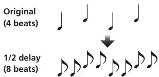
DELAY
This function outputs a delay sound once according to the beat button's fraction. When 1/2 beat delay sound is added, 4 beats become 8 beats.
| Beat buttons (parameter 1) | Use these to set the delay time from 1/8 to 4/1 with respect to 1 beat of BPM time. |
| TIME (parameter 2) | Use this to set the delay time. 1 to 4000 (ms) |
| LEVEL/DEPTH (param- eter 3) | Use this to set the balance between the original sound and the delay sound. |
| EFFECT FREQUENCY -parameter 4) | Use these to set the balance between the original sound and the delay sound for the different bands. |
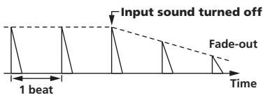
ECHO
This function outputs increasingly attenuated delay sounds several times according to the beat button's fraction. With 1/1 beat echoes, the delay sounds are faded out according to the track's tempo even after the input sound has been cut.
| Beat buttons (parameter 1) | Use these to set the delay time from 1/8 to 4/1 with respect to 1 beat of BPM time. |
| TIME (parameter 2) | Use this to set the delay time. 1 to 4000 (ms) |
| LEVEL/DEPTH (param-eter 3) | Use this to set the balance between the original sound and the echo sound. |
| EFFECT FREQUENCY parameter 4) | Use these to set the balance between the original sound and the echo for the different bands. |
MULTI TAP DELAY
This function outputs up to 7 delay sounds in 1/8 units, according to the beat button's fraction.
The volume of the delay sound can be adjusted with the [EFFECT FREQUENCY] controls.
The volume of the odd delay sounds is adjusted from [MIN] to the center position, the volume of the even delay sounds is adjusted from the center position to [MAX].
| Beat buttons (parameter 1) | The effect time is set from 1/8 to 4/1 with respect to 1 beat of BPM time. |
| TIME (parameter 2) | Use this to set the delay time. 10 to 4000 (ms) |
| LEVEL/DEPTH (param-eter 3) | Use this to set the balance between the original sound and the delay sound. |
| EFFECT FREQUENCY parameter 4) | This sets the volume of the delay sound for the different bands. |
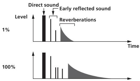
REVERB
This function adds a reverberation effect to the input sound.
| Beat buttons (parameter 1) | These set the degree of the reverb effect from 1 to 100%. |
| TIME (parameter 2) | Use this to set the degree of the reverb effect. 1 to 100 (%) |
| LEVEL/DEPTH (param- eter 3) | Sets the balance between the original sound and the effect sound. |
| EFFECT FREQUENCY -parameter 4) | Use these to set the balance between the original sound and the effect sound for the different bands. |
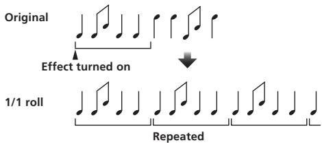
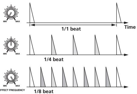
ROLL
This function records the input sound at the point at which the [ON/OFF] button is pressed and repeats the recorded sound according to the beat button's fraction.
| Beat buttons (parameter 1) | The effect time is set from 1/8 to 4/1 with respect to 1 beat of BPM time. |
| TIME (parameter 2) | Use this to set the effect time. 10 to 4000 (ms) |
| LEVEL/DEPTH (param-eter 3) | Use this to set the balance between the original sound and ROLL. |
| EFFECT FREQUENCY (parameter 4) | Use these to set the balance between the original sound and the ROLL for the different bands. |
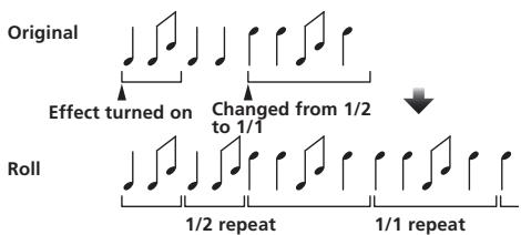
SLIP ROLL
This function records the input sound at the point at which the [ON/OFF] button is pressed and repeats the recorded sound according to the beat button's fraction.
When the effect time changes, the input sound is recorded again.
| Beat buttons (parameter 1) | The effect time is set from 1/8 to 4/1 with respect to 1 beat of BPM time. |
| TIME (parameter 2) | Use this to set the effect time. 10 to 4000 (ms) |
| LEVEL/DEPTH (param-eter 3) | Use this to set the balance between the original sound and ROLL. |
| EFFECT FREQUENCY (parameter 4) | Use these to set the balance between the original sound and the ROLL for the different bands. |
REVROLL
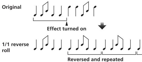
This function records the input sound at the point at which the [ON/OFF] button is pressed, reverses the recorded sound and repeats it according to the beat button's fraction.
| Beat buttons (parameter 1) | The effect time is set from 1/8 to 4/1 with respect to 1 beat of BPM time. |
| TIME (parameter 2) | Use this to set the effect time. 10 to 4000 (ms) |
| LEVEL/DEPTH (param-eter 3) | Use this to set the balance between the original sound and ROLL. |
| EFFECT FREQUENCY (parameter 4) | Use these to set the balance between the original sound and the ROLL for the different bands. |
FILTER
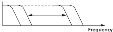
This function changes the filter's cut-off frequency according to the beat button's fraction.
| Beat buttons (parameter 1) | These set the cycle for moving the cut-off frequency from 1/8 to 4/1 with respect to 1 beat of BPM time. |
| TIME (parameter 2) | Use this to set the cycle at which the cut-off frequency is moved. 10 to 32000 (ms) |
| LEVEL/DEPTH (param-eter 3) | The further the control is turned clockwise, the more the effect is stressed. |
| EFFECT FREQUENCY (parameter 4) | These set the balance between the original sound and the effect sound for the different bands. |
TRANS
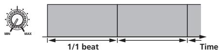
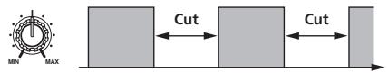
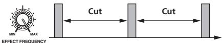
This function cuts the sound according to the beat button's fraction.
The amount of the sound to be cut can be changed at [EFFECT FREQUENCY].
| Beat buttons (parameter 1) | These set the 1/8 to 4/1 cut time with respect to 1 beat of BPM time. |
| TIME (parameter 2) | Use this to set the effect time. 10 to 16000 (ms) |
| LEVEL/DEPTH (param-eter 3) | Sets the balance between the original sound and the effect sound. |
| EFFECT FREQUENCY (parameter 4) | This sets the amount of the original sound to be cut for the different bands. |
PHASER
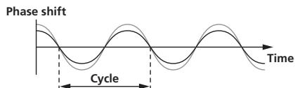
The phaser effect changes according to the beat button fraction.
| Beat buttons (parameter 1) | These set the cycle for moving the phaser effect by 1/8 to 4/1 with respect to the time of one BPM beat. |
| TIME (parameter 2) | This sets the cycle by which the phaser effect is moved. 10 to 32000 (ms) |
| LEVEL/DEPTH (param-eter 3) | The further the control is turned clockwise, the more the effect is stressed. When turned all the way counterclockwise, only the original sound is output. |
| EFFECT FREQUENCY (parameter 4) | Use these to set the balance between the original sound and the effect sound for the different bands. |
GATE
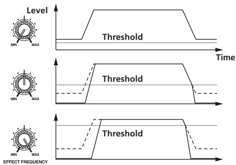
This function outputs the input sound that has a level above the threshold level, cutting the input sound that has a level below the threshold level. The threshold level can be changed at [EFFECT FREQUENCY].
| Beat buttons (parameter 1) | This sets the release time between 1 and 100 %. |
| TIME (parameter 2) | This sets the release time. 1 to 100 %) |
| LEVEL/DEPTH (param-eter 3) | Sets the threshold level. The further the control is turned clockwise, the more the effect is stressed and the sound is cut. |
| EFFECT FREQUENCY (parameter 4) | Use these to set the threshold levels for the different bands. |
SEND/RETURN
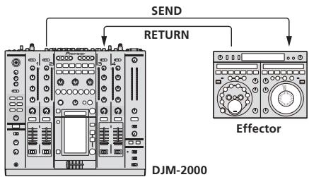
Connect an external effector, etc., here. [EFFECT FREQUENCY] can be used as an isolator.
| Beat buttons (parameter 1) | — |
| TIME (parameter 2) | — |
| LEVEL/DEPTH (param-eter 3) | This adjusts the sound level input to the [RETURN] terminal. |
| EFFECT FREQUENCY (parameter 4) | This sets the audio output level of the RETURN sound for the different bands. |
When "A", "B" or "M" is selected with the [CH SELECT] buttons, the effect sound cannot be monitored by pressing [CUE] (BEAT EFFECT) unless the sound for the channel you want to monitor is being output from [MASTER] channel.
2 When BEAT EFFECT is off, the effect sound cannot be monitored by pressing [CUE] (BEAT EFFECT).
Changing the settings
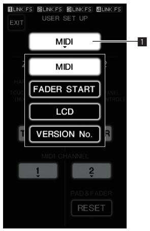
1 Setup item button
1 Press [LIVE SAMPLER (UTILITY, WAKE UP)] for at least 1 seconds.
The [USER SETUP] screen appears.
The [LIVE SAMPLER (UTILITY, WAKE UP)] indicator flashes.
- To display the [CLUB SETUP] screen, first turn this unit's power off, then press [POWER] while pressing [LIVE SAMPLER (UTILITY, WAKE UP)].
2 Press the setup item button.
The selection items appear.
3 Select the setup item.
Select the item on the touch panel and enter it.
4 Change the item's setting.
Select the item on the touch panel and enter it.
- Press [SAVE] to save the changes to the [CLUB SETUP] screen.
5 Press [EXIT].
The [USER SETUP] screen closes.
- To close the [CLUB SETUP] screen, press [POWER] to turn this unit's power off.
Setting preferences
Settings indicated in italics are the default settings set upon purchase.
| Mode | Options settings | Selection item 1 | Selection item 2 | Selection item 3 | Descriptions |
| USER SETUP | MIDI | ZONE1① | BUTTON ACTION | TOGGLE | Select the MIDI signal sending method, [TOGGLE] or [TRIGGER]. |
| TRIGGER | |||||
| MIDI CHANNEL | 1, 2, to 16 | Sets the MIDI channel. | |||
| ZONE2② | BUTTON ACTION | TOGGLE | Select the MIDI signal sending method, [TOGGLE] or [TRIGGER]. | ||
| TRIGGER | |||||
| MIDI CHANNEL | 1, 2, to 16 | Sets the MIDI channel. | |||
| RESET | — | Restores the [TYPE A] - [TYPE D] MIDI settings to the default values. [RESET] function is unique to [ZONE2]. | |||
| FADER START | LINK | CH1 to CH4 | ON, OFF | Turns the fader start function of the DJ players connected to the [LINK] terminals on and off. | |
| CONTROL | CH2, CH3 | ON, OFF | Turns the fader start function of the DJ players connected to the [CONTROL] terminals on and off. | ||
| LCD | BACK LIGHT | 1, 2, 3, 4, 5 | — | Adjusts the touch panel's brightness. | |
| VERSION No. | — | — | — | Displays the DJM-2000's software version. | |
| CLUB SETUP | SYSTEM | DIGITAL OUT MAX LEVEL | -19 dB, -15 dB, -10 dB, -5 dB | — | Adjusts the maximum audio level output from the [DIGITAL OUT] terminal. |
| DIGITAL SAMPLING RATE | 48 kHz, 96 kHz | — | Switches the digital signal sampling rate. | ||
| AUTO STANDBY | ON, OFF | — | Turns the auto standby function on and off. | ||
| MIC | OUTPUT TO BOOTH MONITOR | ON, OFF | — | Sets whether or not to output the microphone's audio signals from [BOOTH] terminals. | |
| TALK OVER THRESH-OLD LEVEL | -25 dB, -20 dB, -15 dB, -10 dB | — | Sets the talkover sensitivity. The talkover function is activated when a sound with a volume above the set volume is input to the microphone. | ||
| TALK OVER LEVEL | -25 dB, -20 dB, -15 dB, -10 dB | — | Sets the attenuation level for the sound other than the microphone's sound when the talkover function is activated. | ||
| TOUCH PANEL | — | — | — | The touch panel's calibration is adjusted by pressing [+] in order. | |
| FACTORY RESET | YES, NO | — | — | Restores all the settings to their factory defaults. |
1 Changes the MIDI settings of the buttons on the control panel, [FREQUENCY MIX] and [SIDECHAIN REMIX].
Changes the MIDl settings for [TYPE A] to [TYPE D] on the MIDl control screen.
About the auto standby function
When [AUTO STANDBY] is set to [ON], the standby mode is set automatically if 4 hours pass with all of the conditions below met.
- That none of this unit's buttons or controls are operated.
- That no audio signals of -10 dB or greater are input to this unit's input terminals.
- That no PRO DJ LINK connections are made.
- The standby mode is canceled when [LIVE SAMPLER (UTILITY, WAKE UP)] is pressed.
Additional information
Troubleshooting
Incorrect operation is often mistaken for trouble or malfunction. If you think that there is something wrong with this component, check the points below. Sometimes the trouble may lie in another component. Inspect the other components and electrical appliances being used. If the trouble cannot be rectified after checking the items below, ask your nearest Pioneer authorized service center or your dealer to carry out repair work.
- The player may not operate properly due to static electricity or other external influences. In such cases, normal operation may be restored by unplugging the power cord then plugging it back in.
| Problem | Check | Remedy |
| The power is not turned on. | Is the power cord properly connected? | Plug in the power cord to an AC outlet. |
| No sound or small sound. | Is the [CD/DIGITAL, PHONO, LINE, USB */] switch set to the proper position? | Switch the [CD/DIGITAL, PHONO, LINE, USB */] switch to the channel's input source. (page 13) |
| Are the [CD, DIGITAL] switches on the rear panel properly set? | Set the [CD, DIGITAL] switches according to the devices to be played. (page 13) | |
| Are the connection cables properly connected? | Connect the connection cables properly. (page 8) | |
| Are the terminals and plugs dirty? | Clean the terminals and plugs before making connections. | |
| Is the [MASTER ATT.] switch on the rear panel set to [-6 dB], etc.? | Switch the [MASTER ATT.] switch. (page 7) | |
| Digital sound cannot be output. | Is the digital audio output's sampling frequency (fs) suited for the specifications of the connected device? | On the [CLUB SETUP] screen, set [DIGITAL SAMPLING RATE] according to the specifications of the connected equipment. (page 25) |
| Distorted sound. | Is the level of audio output from the microphone channel properly set? | Adjust the [MASTER] control so that the master channel level indicator lights at about [0 dB] at the peak level. (page 13) |
| Set [MASTER ATT.] to [-3 dB] or [-6 dB]. (page 7) | ||
| Is the level of audio input to each channel properly set? | Adjust the [TRIM] control so that the channel level indicator lights at about [0 dB] at the peak level. (page 13) | |
| Can't crossfade. | Is the [CROSS FADER ASSIGN] switch properly set? | Set the channel's [CROSS FADER ASSIGN] switch properly. (page 13) |
| Can't fader start a DJ player. | Is [FADER START] set to off? | Set [FADER START] to on at the [USER SETUP] screen. (page 14) |
| Is the DJ player properly connected to the [CONTROL] terminal? | Connect the [CONTROL] terminal and DJ player using a control cord. (page 8) | |
| Is the DJ player properly connected to the [LINK] terminal? | Connect the DJ player to the [LINK] terminal properly using a LAN cable. (page 8) | |
| Are the audio cables properly connected? | Connect this unit's audio input terminals and the DJ player's audio output terminals by audio cable. (page 8) | |
| BEAT EFFECT function does not work. | Are the [CH SELECT] buttons properly set? | Press the [CH SELECT] button(s) to select the channel(s) to which you want to add the effect. |
| [INST FX] does not work. | Is the [FILTER] control set to the proper position? | Turn the [FILTER] control clockwise. (page 16) |
| Can't use an external effector. | Is [ON/OFF] for the BEAT EFFECT set to on? | Press [ON/OFF] for the BEAT EFFECT to turn [SEND/RETURN] on. (page 17) |
| Is the external effector properly connected to the [SEND] or [RETURN] terminal? | Connect the external effector to the [SEND] and [RETURN] terminals. (page 8) | |
| Distorted sound from an external effector. | Is the external effector's audio output level set to an appropriate level? | Adjust the external effector's audio output level. |
| Tempo (BPM) cannot be measured or measurement value of tempo (BPM) is implausible. | Is the audio input level too high or too low? | Adjust the [TRIM] control so that the channel level indicator lights at about [0 dB] at the peak level. (page 13) |
| For some tracks, it may not be possible to measure the tempo (BPM). In this case, input the tempo manually using the [TAP] button. (page 17) | ||
| Measured tempo (BPM) differs from tempo indicated on CD. | — | The values may differ slightly due to the different ways in which the BPM is measured. There is no need to make any corrections. |
| MIDI sequencer does not synchronize. | Is the MIDI sequencer's sync mode set to Slave? | Set the MIDI sequencer's sync mode to Slave. |
| Does the MIDI sequencer you are using support MIDI timing clocks? | MIDI sequencers not supporting MIDI timing clocks cannot be synchronized. | |
| MIDI control does not work. | Is the MIDI channel turned on? | Press [ON/OFF] in the [MIDI] section. (page 17) |
| Are the MIDI settings properly set? | To operate DJ software with this unit, this unit's MIDI messages must be assigned to the DJ software you are using. For instructions on assigning messages, see your DJ software's operating instructions. | |
| This unit is not recognized after it has been connected to a computer. | Is the driver software properly installed on your computer? | Install the driver software. If the software is already installed, re-install it. (page 9) |
| Sound of a computer cannot be output from this unit. | Are this unit and computer properly connected? | Connect this unit and computer using a USB cable. (page 9) |
| Are the audio output device settings properly set? | Select this unit with the audio output device settings. For instructions on making settings for your application, see your application's operating instructions. | |
| Is this unit's input selector switch properly set? | Set the channel's input selector switch to the [USB */] position. (page 13) | |
| Nothing happens when touch panel is pressed. | Touch panel's calibration is off. | Adjust the touch panel with the [TOUCH PANEL] settings at the [CLUB SETUP] screen. (page 25) |
| The effect sound cannot be monitored when [CUE] for the BEAT EFFECT is pressed. | — | The circuit that generates the echo for the [ECHO], [REVERB], [ROLL], [SLIP ROLL] and [REV ROLL] effect sounds is positioned after the effect circuit, so the effect sound cannot be monitored. This is not a malfunction. |
About the liquid crystal display
- Small black or shining points may appear on the liquid crystal display. This is a phenomenon inherent to liquid crystal displays; this is not a malfunction.
- When using in cold places, the liquid crystal display may be dark for a while after the DJM-2000's power is turned on. It will reach the normal brightness after a while.
- When the liquid crystal display is exposed to direct sunlight, the light will reflect off it, making it difficult to see. Block the direct sunlight.
About the exemption clauses
- Pioneer is a registered trademark of Pioneer Corporation.
- Microsoft®, Windows Vista®, and Windows® are registered trademarks or trademarks of Microsoft Corporation in the United States and/or other countries.
- Pentium is a registered trademark of Intel Corporation.
- Adobe and Reader are either registered trademarks or trademarks of Adobe Systems Incorporated in the United States and/or other countries.
- Apple, Macintosh or Mac OS are registered trademarks of Apple Inc. in the United States and/or other countries.
ASIO is a trademark of Steinberg Media Technologies GmbH. - The names of companies and products mentioned herein are the trademarks of their respective owners.
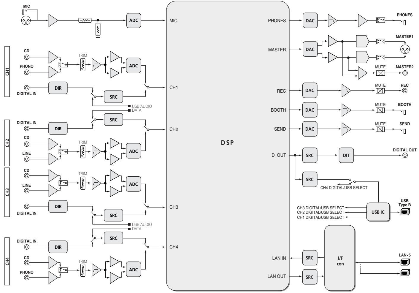
Block Diagram
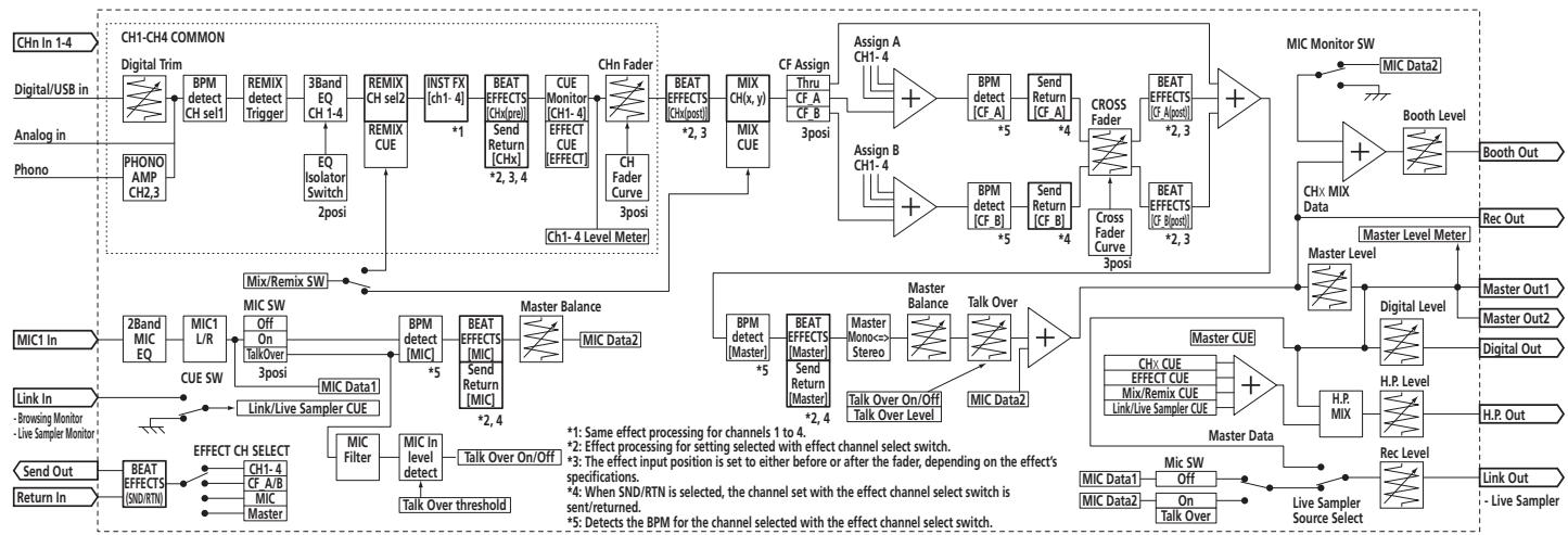
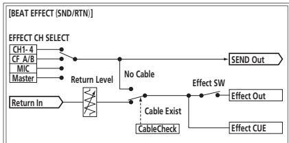
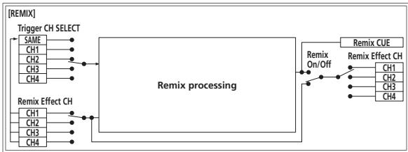
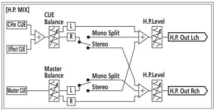
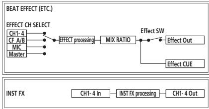
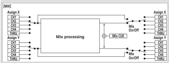
Specifications
General
Power requirements.. AC 120 V, 60 Hz
Power consumption 42 W
Power consumption (standby) .0.4 W
Main unit weight. 8.5 kg (18.7 lb)
External dimensions. 430 mm (W) x 107.9 mm (H) x 409 mm (D)
(16.9 in. (W) x 4.3 in. (H) x 16.1 in. (D))
Tolerable operating temperature. +5^ to +35^ (+41^ to +95^)
Tolerable operating humidity. 5% to 85% (no condensation)
Audio Section
Sampling rate 96 kHz
A/D, D/A converter. 24 bits
Frequency characteristic
CD/LINE/MIC 20 Hz to 20 kHz
S/N ratio (rated output)
PHONO 93 dB
CD/DIGITAL LINE 107 dB
MIC. 85 dB
Total harmonic distortion (LINE - MASTER1) 0.004 %
Standard input level / Input impedance
PHONO. -52 dBu/47 kΩ
CD/LINE -12 dBu/47 kΩ
MIC. -52 dBu/8 kΩ
RETURN. -12 dBu/47 kΩ
Standard output level / Load impedance / Output impedance
MASTER1 +8dBu / 10k /1 or lower
MASTER2 +2dBu / 10k /22 or lower
REC OUT. 8 dBu/10 kΩ/22 Ω or lower
BOOTH +8dBu / 10k /1k or lower
SEND. -12 dBu/10 kΩ/1 kΩ or lower
PHONES. +8.5dBu / 32 /1 or lower
Rated output level / Load impedance
MASTER1 +26 dBu/10 kΩ
MASTER2 +20 dBu/10 kΩ
Crosstalk (LINE) 82 dB
Channel equalizer characteristic
HI. -26 dB to +6 dB (13 kHz)
MID -26 dB to +6 dB (1 kHz)
LOW. -26 dB to +6 dB (70 Hz)
Microphone equalizer characteristic
HI. -12 dB to +12 dB (10 kHz)
LOW. -12 dB to +12 dB (100 Hz)
Input / Output terminals
PHONO input terminal
RCA pin jack 2
CD input terminal RCA pin jack 4
LINE input terminal
RCA pin jack 2
MIC input terminal
XLR connector/Phone jack (6.3 mm) 1
RETURN Input terminals
Phone jack (6.3 mm) 1
DIGITAL IN coaxial input terminal
RCA pin jack 4
MASTER output terminal
XLR connector 1
RCA pin jack 1
BOOTH output terminal
Phone jack (6.3 mm) 1
REC OUT output terminal
RCA pin jack 1
SEND output terminal
Phone jack (6.3 mm) 1
DIGITAL OUT coaxial output terminal
RCA pin jack 1
MIDI OUT terminal
5PDIN 1
PHONES output terminal
Stereo phone jack (6.3 mm) 1
USB terminal
B-type 1
CONTROL terminal
Mini phone jack (0 3.5 mm) 2
LINK terminal
LAN terminal (100Base-TX) 6
The specifications and design of this product are subject to change without notice.
IMPORTANT

Exportation SD & USB
ExportationrekordboxLINK
LIVE SAMPLER
LINK MONITOR
STATUS INFORMATION
CARTE SON
Exportation SD & USB
To register your product, find the nearest authorized service location, to purchase replacement parts, operating instructions, or accessories, please go to one of following URLs :
http://www.pioneerelectronics.com
In Canada/Aux Canada
http://www.pioneerelectronics.ca
S018_B1_EnFr
Published by Pioneer Corporation.
Copyright © 2010 Pioneer Corporation.
All rights reserved.
Publication de Pioneer Corporation.
© 2010 Pioneer Corporation.