
RM-72.13 H - Riding lawn mower DOLMAR - Free user manual and instructions
Find the device manual for free RM-72.13 H DOLMAR in PDF.


User questions about RM-72.13 H DOLMAR
0 question about this device. Answer the ones you know or ask your own.
Ask a new question about this device
Download the instructions for your Riding lawn mower in PDF format for free! Find your manual RM-72.13 H - DOLMAR and take your electronic device back in hand. On this page are published all the documents necessary for the use of your device. RM-72.13 H by DOLMAR.
USER MANUAL RM-72.13 H DOLMAR
8 ACCESSORIES OPTIONNELS 42
L'emballage standard contient:
REEMPLACEMENT D'UN FUSIBLE
8. ACCESSORIES OPTIONNELS
1. CONTRE-POIDS FRONTAUX
We thank you for having purchased our riding mower and hope that it will fully meet all your expectations.
This manual has been compiled in order that you may get to know your machine and to be able to use it safely and efficiently. Don't forget that the manual forms an integral part of the machine so keep it handy so that it can be consulted at any time, and pass it on to the purchaser if you resell the machine.
Your new machine has been designed and made in line with current regulations, and is safe and reliable if used for cutting and collecting grass observing the indications given in this manual (proper usage). Using the machine in any other way or ignoring the instructions for safe usage, maintenance or repair, is considered "incorrect usage" which will invalidate the guarantee, and the manufacturer will decline all responsibility, placing the blame with the user for damage or injury to himself or others in such cases.
If you should find any slight differences between the description and your own machine, bear in mind that, since there are continual improvements to the product, information contained in this manual may be modified without prior warning and without the obligation to update it, although the essential safety and function characteristics will remain unaltered. In case of any doubts, do not hesitate to contact your Retailer or a Licensed Service Centre.
AFTER-SALES SERVICE
This manual gives all the necessary instructions for using the machine and the basic maintenance that may be carried out by the user.
For all information not contained here, contact the Local Retailer or a Licensed Service Centre.
If you wish, your Retailer will be pleased to offer a maintenance programme personalised to your needs. Like this you will be able to keep your new acquisition in peak performance, maintaining its value.
TABLE OF CONTENTS
- SAFETY 3
Regulations for using the machine safely
- IDENTIFICATION OF THE MACHINE AND PARTS 7
Explanations on how to identify the machine and its main parts
- UNPACKING AND ASSEMBLY 9
Explanations on how to remove the packing and on how to assemble separated parts
- COMMANDS AND CONTROL INSTRUMENTS 13
Position and functions of all the controls
- HOW TO USE THE MACHINE 17
Provides indications for working efficiently and safely
5.1 Directions before starting 17
5.2 Starting and moving 20
5.3 Grass cutting 22
5.4 Cleaning and storage 27
- MAINTENANCE 29
All the information for maintaining the machine in peak efficiency
- TROUBLESHOOTING 39
A help in quickly resolving any problems
8 ACCESSORIES ON REQUEST 42
A description of the accessories available for particular types of work
- SPECIFICATIONS 43
A summary of the main specifications of your machine
1. SAFETY
HOW TO READ THE MANUAL
This manual describes both mechanically and hydrostatically driven machines, as well as versions including equipment and accessories that may not be available in your area.
The symbol highlights all differences in usage and is followed by the indication of the type of drive or version to which it refers.
Some paragraphs in the manual contain information of particular importance and these are highlighted at various levels of emphasis, and signify the following:
NOTE or IMPORTANT These give details or further information on what has already been said, and are aimed at preventing damage to the machine or causing damage.
WARNING! Non-observation will result in the risk of injury to oneself or others.
DANGER! Non-observation will result in the risk of serious injury or death to oneself or others.
SAFETY REGULATIONS
(read carefully before using the machine)
A) TRAINING
1) Read the instructions carefully. Be familiar with the controls and the proper use of the equipment. Learn how to stop the engine quickly.
2) Only use the machine for the purpose for which it was made, that is, the cutting and collection of grass. Any use not specifically indicated in the Operator's Manual can be dangerous and result in damage to the machine, and will also result in the annulling of the warranty and the manufacturer declining all responsibility.
3) Never allow children or people unfamiliar with these instructions to use the machine. Local regulations may restrict the age of the operator.
4) Never use the machine:
- when people, especially children, or pets are nearby.
- if the operator has taken medicine or substances that can affect his ability to react and concentrate.
5) Keep in mind that the operator or user is responsible for accidents or hazards occurring to other people or their property.
6) Do not carry passengers.
7) The operator of a machine must carefully follow the driving instructions, particularly:
- the need for care and concentration when using machines;
- that control of a machine sliding on a slope will not be regained by the application of the brake.
The main reasons for loss of control are:
- insufficient wheel grip;
- being driven too fast;
- inadequate braking;
- the type of machine is unsuitable for its task;
- lack of awareness of the effect of ground conditions, especially slopes;
8) The machine is equipped with a series of safety microswitches and devices which must never be removed, altered or tampered with. Removing these devices invalidates the warranty and the manufacturer declines any responsibility.
B) PREPARATION
1) While mowing, always wear substantial footwear and long trousers. Do not operate the equipment when barefoot or wearing open sandals.
2) Thoroughly inspect the area where the equipment is to be used and remove all objects which may be thrown by the machine (stones, sticks, metal wire, bones, etc.)
3) WARNING: DANGER! - Engine fuel is highly flammable:
- store fuel in containers specifically designed for this purpose;
- refuel using a funnel and outdoors only. Do not smoke while refuelling or whenever handling the fuel;
- add fuel before starting the engine. Never remove the cap of the fuel tank or add fuel while the engine is running or when the engine is hot;
- if fuel is spilled, do not attempt to start the engine but move the machine away from the area of spillage and avoid creating any source of ignition until the fuel has evaporated and the fumes dispersed;
- replace caps of all fuel tanks and containers securely.
4) Replace faulty silencers.
5) Before using, always carry out a visual inspection, particularly of the blade, seeing that the screws and cutter assembly are not worn or damaged. Replace a worn or damaged blade and screws as a set to preserve balance.
6) Before mowing, attach the discharge opening guards (grass-catcher or stone-guard).
C) OPERATION
1) Do not operate the engine in a confined space where dangerous carbon monoxide fumes can collect.
2) Mow only in daylight or good artificial light.
3) Avoid operating the equipment in wet grass, where feasible.
4) Before starting the engine, disengage the blade, shift the gear lever (for mechanical drive models) or the speed change lever (for hydrostatic drive models) into neutral and engage the parking brake.
5) Do not use slopes of more than 10^ (17%).
6) Remember there is no such thing as a "safe" slope. Travel on grass slopes requires particular care. To guard against overturning:
- it is advisable to use a front counterweight (supplied on request);
- do not stop or start suddenly when going up or downhill;
- engage clutch slowly, always keep the machine in gear (for mechanical drive models) or engage the speed change lever slowly both for forward and reverse movement (for hydrostatic drive models), especially when travelling downhill;
- machine speeds should be kept low on slopes and during tight turns;
- stay alert for humps and hollows and other hidden hazards;
- never mow across the face of the slope.
7) Stop the blade rotating and put the cutting deck into the highest position before
crossing surfaces other than grass.
8) Never use the machine to cut grass if the guards are defective, or without the stone-guard and/or grass-catcher in place.
9) Do not change the engine governor settings or overspeed the engine.
10) Before leaving the operator's position:
-
disengage the blade;
-
change into neutral ( or mechanical drive models) or make sure that the speed change lever has returned to the neutral position ( or hydrostatic drive models) and engage the parking brake;
- stop the engine and remove the key.
11) Disengage the blade, stop the engine and remove key: - before carrying out any work beneath the cutting deck or unclogging the collector channel;
- before checking, cleaning or working on machine;
- after striking a foreign object. Inspect the machine for damage and make repairs before restarting and operating the machine;
- if the machine starts to vibrate abnormally (immediately check and remove the cause of the vibration).
12) Disengage the blade when transporting or not in use. Disengage the blade and wait for it to stop before emptying the grass-catcher.
13) Stop the engine and disengage the blade: - before refuelling;
- every time the grass-catcher is removed or replaced.
14) Reduce the throttle setting before stopping the engine and turn the fuel off at the conclusion of mowing, following the instructions in the manual.
15) Do not put hands or feet near or under rotating parts. Keep clear of the discharge opening at all times.
1) Keep all nuts, bolts and screws tight to be sure the equipment is in safe working condition. Regular maintenance is essential for safety and for maintaining performance levels.
2) Never store the equipment with fuel in the tank inside a building where fumes may reach a flame or a spark or a source of extreme heat.
3) Allow the engine to cool before storing in an enclosed space.
4) To reduce the fire hazard, keep the engine, exhaust silencer, battery compartment and fuel storage area free of grass, leaves, or excessive grease. Always empty the grass-catcher and do not leave garden rubbish containers inside a room.
5) Frequently check the stone-guard, the grass-catcher and the air intake grill for wear and deterioration. Replace if damaged.
6) For reasons of safety, do not use equipment with worn or damaged parts. Parts are to be replaced and not repaired. Use genuine spare parts (the blade should always bear the symbol ). Parts which are not of an equivalent quality can damage the equipment and may adversely affect your safety.
7) If the fuel tank has to be drained, this should be done outdoors and when the engine is cool.
8) Wear strong work gloves when removing and reassembling the blade.
9) Check the blade's balance after sharpening.
10) When the machine is to be parked, stored or left unattended, lower the cutting deck.
11) The ignition key must never be left inserted in the machine, or where children or persons not familiar to the machine may reach it. Before any maintenance or repair, remove the ignition key.
E) TRANSPORTING
1) If the machine is transported on a truck or trailer, lower the cutting deck, engage the parking brake and fasten the machine securely with ropes, cables or chains to the hauling device.
SAFETY DECALS
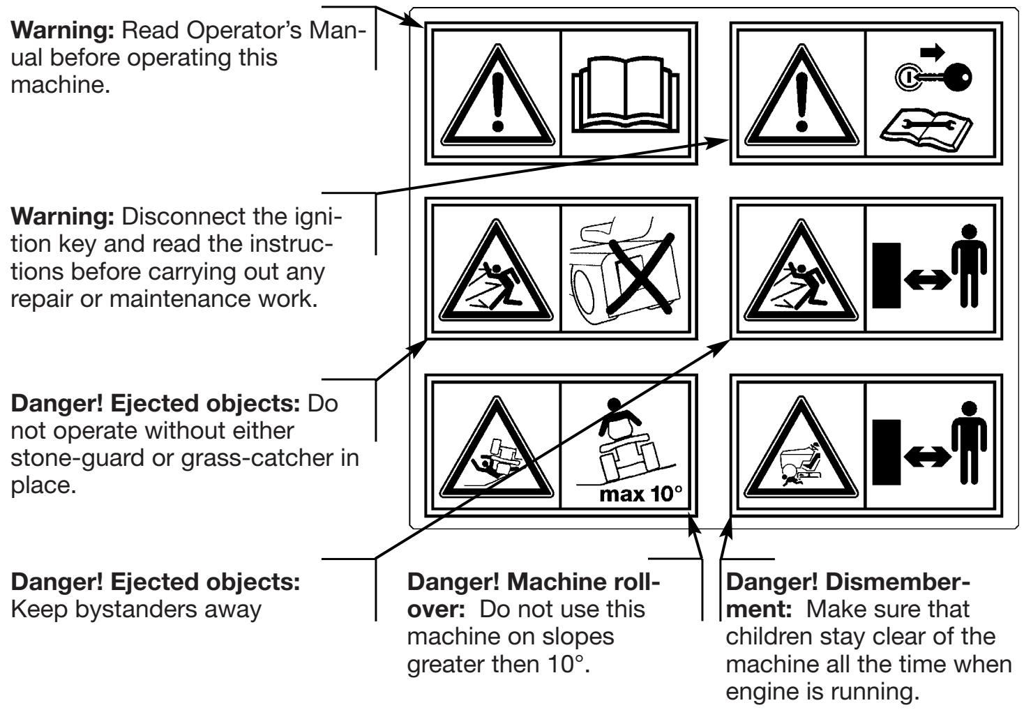
Your machine must be used with care. Therefore, decals have been placed on the machine, to remind you pictorially of the main precautions to take during use. These decals are to be considered an integral part of the machine.
If a decal should fall off or become illegible, contact your retailer to replace it. Their meaning is explained below.
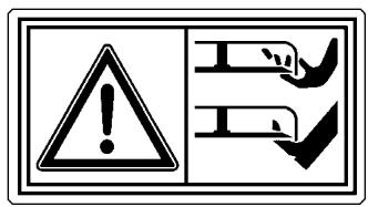
Risk of being cut. Blade in movement. Do not insert hands or feet inside the blade housing.
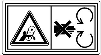
Avoid injury from getting caught in belt: Do not operate the machine without shields in place. Stay clear of belts.
2. IDENTIFICATION OF THE MACHINE AND PARTS
IDENTIFICATION OF THE MACHINE
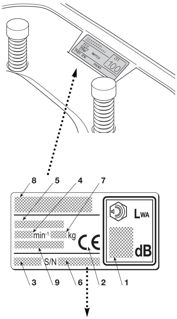
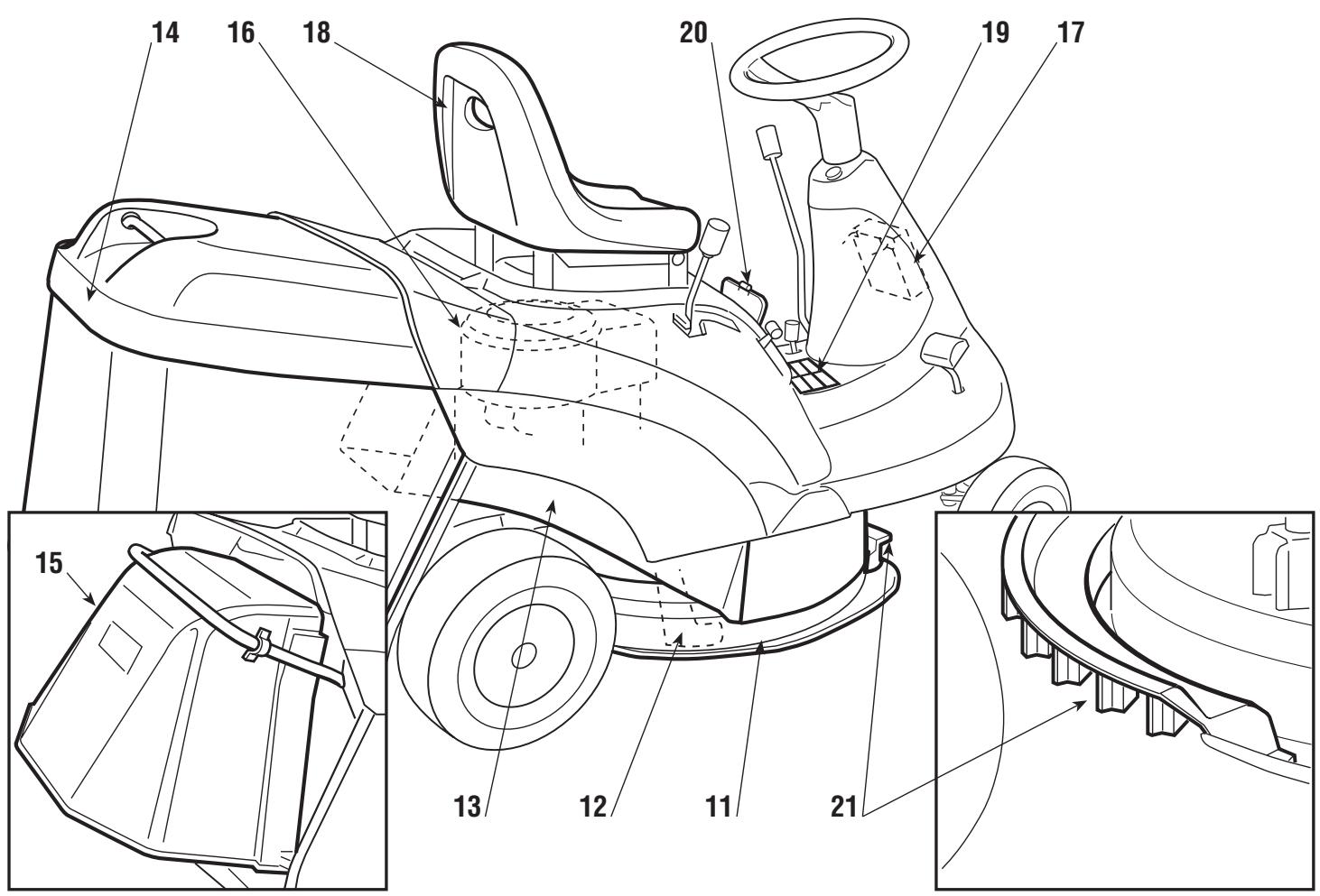
The plate located under the driver's seat has the essential data and serial number of each machine (6).
- Acoustic power level according to directive 2000/14/CE
- Conformity mark according to directive 98/37/EEC
- Year of manufacture
- Operating engine speed in r.p.m (if indicated)
- Type of machine
- Serial number
- Weight in kgs
- Name and address of Manufacturer
- Type of transmission (if indicated)


Write your machine's serial number here
IDENTIFICATION OF MAIN COMPONENTS
Various main components can be seen on the machine, and these have the following functions:
- Cutting deck: this is the guard enclosing the rotating blade.
-
Blade: this is what cuts the grass. The wings at the ends help convey the cut grass towards the collector channel.
-
Collector channel: this is the part connecting the cutting deck to the grass-catcher.
- Grass-catcher: as well as collecting the grass cuttings, this is also a safety element in that it stops any objects drawn up by the blade from being thrown outside of the machine.
- Stone-guard or deflector: this can be fitted in place of the grass-catcher and prevents objects drawn up by the blade from being thrown outside of the machine.
- Engine: this moves the blade and drives the wheels. It is fully described in a specific booklet.
- Battery: provides the energy for starting the engine. It is fully described in a specific booklet.
- Driver seat: this is where the machine operator sits. It has a sensor for detecting the presence of the operator which is a safety device.
- Decals for regulations and safety: give reminders on the main provisions for working safely, each of which is explained in chapter 1.
- Access hatch: gives easy access to the spark plug, the fuel cock, and the fixing nut for the engine cover.
- Air intake grill: helps air to flow inside the cutting deck and prevents objects from being thrown out at the front.
3. UNPACKING AND ASSEMBLY
For storage and transport reasons, some components of the machine are not directly installed in the factory, but have to be assembled after their removal from the packing. Final assembly is carried out by following these simple instructions.
IMPORTANT For transport reasons the machine is supplied without engine oil or fuel. Before starting up the engine, fill with oil and fuel following the instructions given in the engine booklet.
UNPACKING
When unpacking the machine, take care to gather all individual parts and fittings, and do not damage the cutting deck when taking the machine off the base pallet.
The standard packing contents:
- the machine;
- the battery;
- steering wheel;
- seat;
- grass-catcher components;
- an envelope containing the instruction manual, documents and the nuts and bolts with two starter keys, a pin for blocking the steering wheel and a spare 10 Ampere fuse.
ASSEMBLY AND CONNECTING THE BATTERY
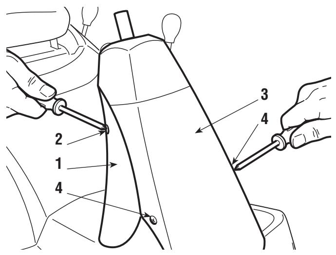
Remove both the rear column cover (1) fastened with two screws (2) and the front column cover (3) fastened with another two screws (4).
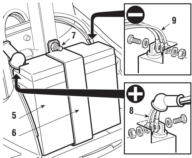
Fit the battery (5) in place and secure it with the bracket (6) and the nut (7).
Connect the three red cables (8) to the positive terminal (+) and the three black cables (9) to the negative terminal (-) using the screws supplied. Follow the instructions given.
Put the column covers (3) and (1) back on with their screws (4) and (2).
Charge the battery following the battery manufacturer's instructions.
IMPORTANT
To prevent the safety device in the electronics card from cut-
ting in, never start the engine until the battery is fully charged!
WARNING!
Follow the battery manufacturer's instructions regarding
safe handling and disposal.
FITTING THE STEERING WHEEL
Put the machine on a flat surface and straighten up the front wheels.
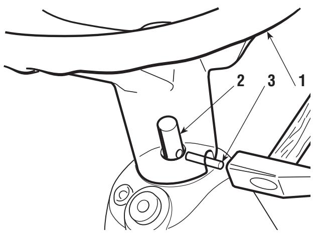
Fit the steering wheel (1) onto the protruding shaft (2) with the spokes directed towards the seat.
Line up the hole in the steering wheel hub with the hole in the shaft and insert the pin supplied (3).
Push the pin in using a hammer, ensuring that it comes completely through to the opposite side.
NOTE
To avoid damaging the steering wheel with the hammer, use
an awl or a screw-driver of the same size as the pin to push it in the last part.
FITTING THE SEAT
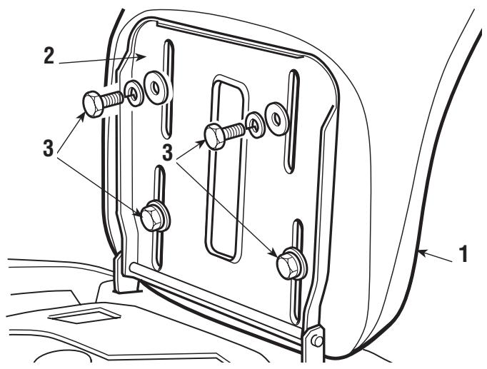
Fit the seat (1) onto the plate (2) using the screws (3).
FITTING THE GRASS-CATCHER
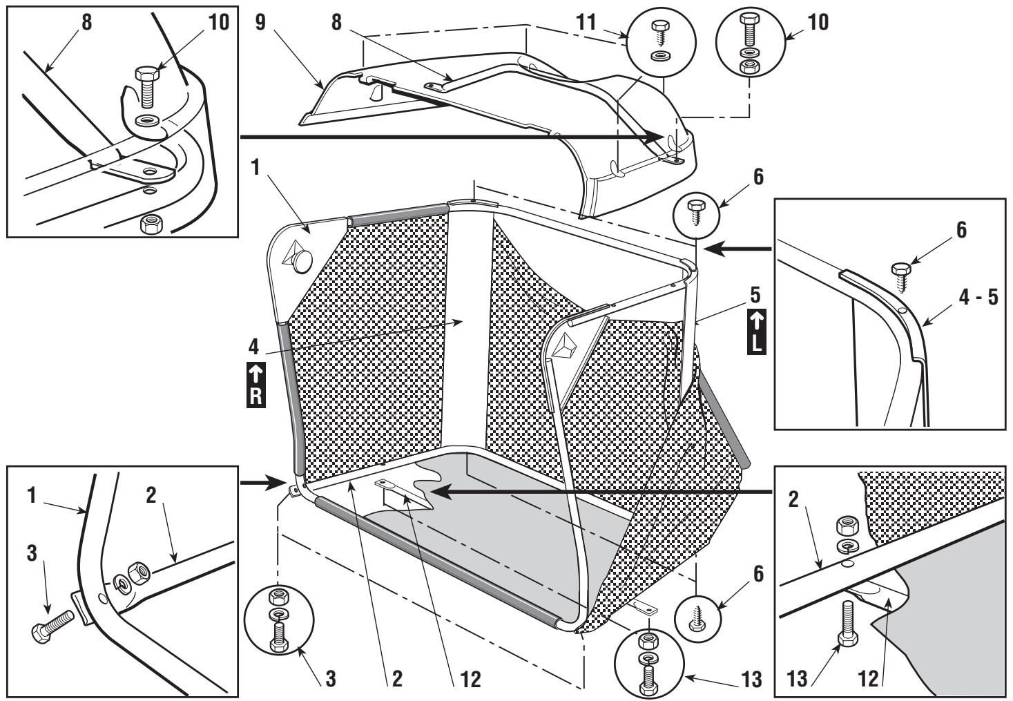
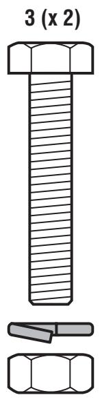
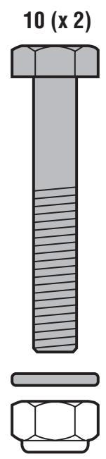
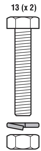
First of all assemble the frame, joining the upper part (1), including the opening, to the lower part (2), using the supplied nuts and screws (3) and following the indicated sequence.
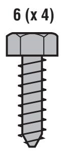
Position the angle supports (4) and (5), respecting the right (R ) and left (L ) sides, and attach them to the frame using the four self-tapping screws (6).
Insert this frame into the canvas cover, ensuring that it is correctly positioned along the base perimeter.
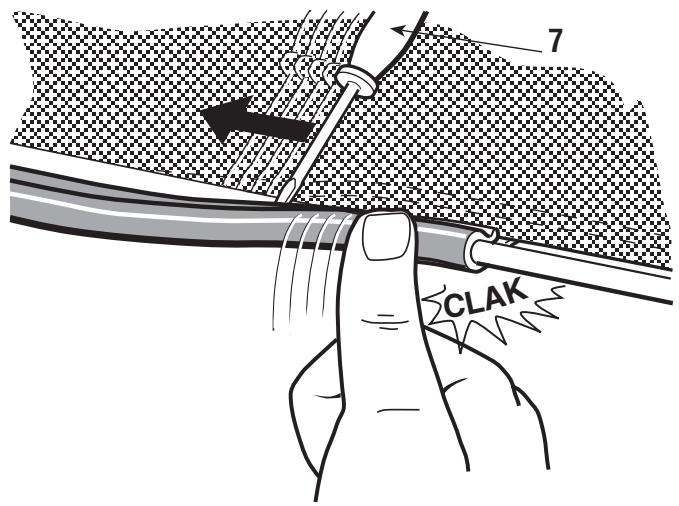
Hook all the plastic profiles to the frame tubes with the help of a screwdriver (7).
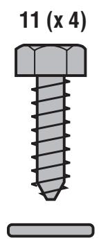
Insert the handle (8) into the holes of the canvas (9). Attach this to the frame using the screws (10), following the indicated sequence, and complete the assembly screwing the four front and rear self-threading screws (11).
Lastly, fit the stiffening bar (12) on the
outside of the frame base, keeping the flat part towards the canvas and using the nuts and screws supplied (13) in the sequence indicated.
4. COMMANDS AND CONTROL INSTRUMENTS
1. STEERING WHEEL
Turns the front wheels.
2. ACCELERATOR LEVER
Regulates the engine's r.p.m. The positions are indicated on a plate showing the following symbols:

Position «CHoke»
for starting up.

Position «SLOW»
for minimum engine speed

Position «FAST»
for maximum engine speed
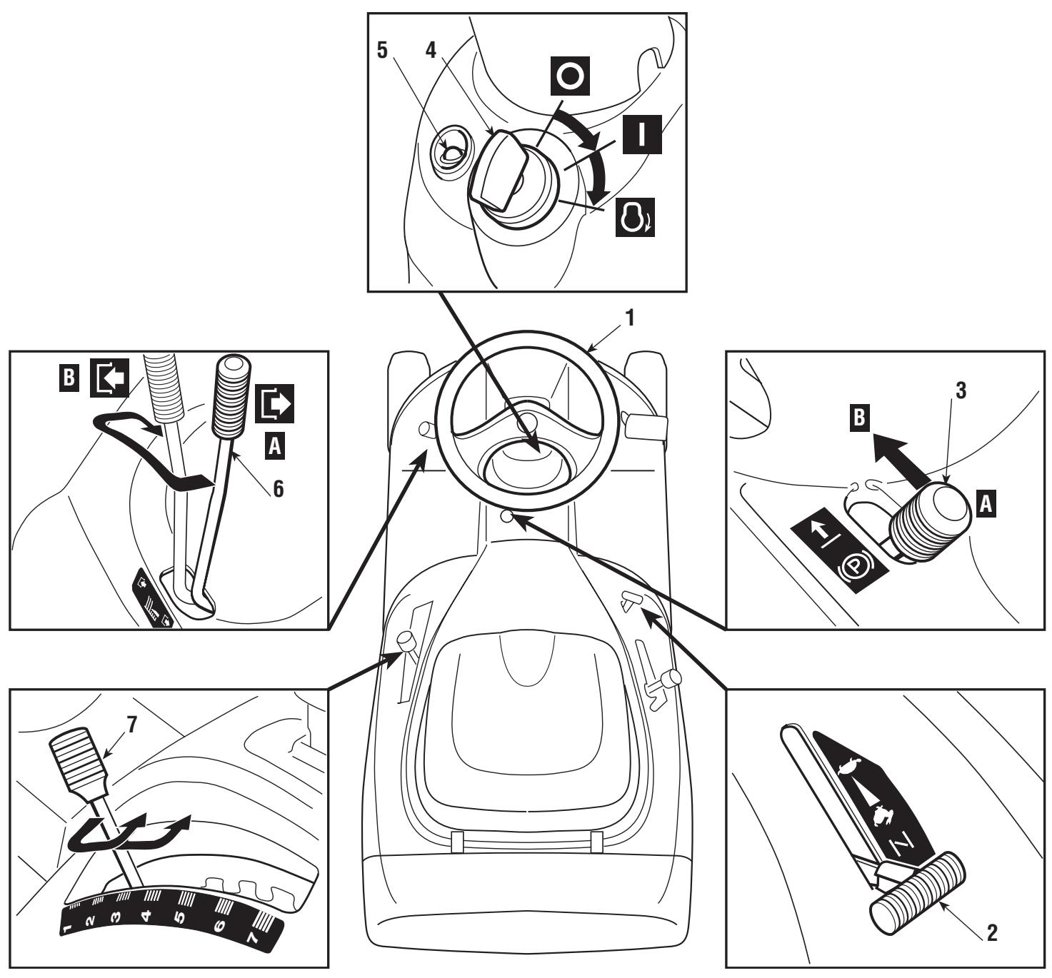
When moving from one area to another, put the lever in a position between «SLOW» and «FAST» When cutting, go to the «FAST» position.
This lever is to stop the machine from moving when it has been parked, and must always be engaged before leaving the machine.
The brake is engaged by fully pressing the pedal (11 - 21) and moving the lever to position «A». When you take your foot off the pedal it will be blocked by the lever in the down position.
To disengage the parking brake, press the pedal again so that the lever returns to position «B».
4. KEY IGNITION SWITCH
This key operated control has three positions:
O <
means everything is switched off
I «ON»
activates all parts
0 «START»
engages the starter motor. On being released, the key will automatically return to «ON» from this position.
5. PILOT LAMP AND SIGNAL
This light comes on when the key (4) is in the «ON» position and remains constantly lit while the machine is operating.
When it starts flashing this means that the engine is being prevented from starting (see page 26).
The audible warning indicates that the grass-catcher is full.
This lever has two positions, as shown on the label:

Position «A»
= BLADE DISENGAGED

Position «B»
= BLADE ENGAGED
If the blade is engaged when safety conditions have not been complied with, the engine shuts down (see page 26).
On disengaging the blade (Pos. «A»), a brake is simultaneously activated which stops it rotating in five seconds.
7. CUTTING HEIGHT ADJUSTING LEVER
There are seven positions for this lever, shown as «1» to «7» on the label, which correspond to various heights of between 3 and 8 cm.
To go from one height to another, move the lever sideways and put into one of the seven notches.
For mechanical drive models:
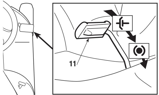
11. CLUTCH / BRAKE PEDAL
This pedal has a double function - during the first part of its travel it acts as a clutch, engaging and disengaging drive to the wheels, and in the second part it acts as a brake on the rear wheels.
It is important not to take too long in using the clutch as this can cause overheating and damage the transmission belt.
NOTE
When the machine
is in movement, keep your foot off the pedal.
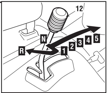
This lever has seven positions for the 5 forward speeds, the neutral position «N», and reverse «R». To go from one speed to another, press the pedal (11) half way and move the lever as per the indications on the label.
WARNING!
Reverse must
only be engaged when the machine is stopped.
For hydrostatic drive models:
21. BRAKE PEDAL
In hydrostatically driven models this pedal is solely for braking and works on the rear wheels.
22. SPEED CHANGE
LEVER
This lever engages drive to the wheels and changes the machine's forward and reverse speed.
The machine's forward speed gradually increases by moving the lever towards «F».
Reverse is engaged by moving the lever to «R».
When the brake pedal
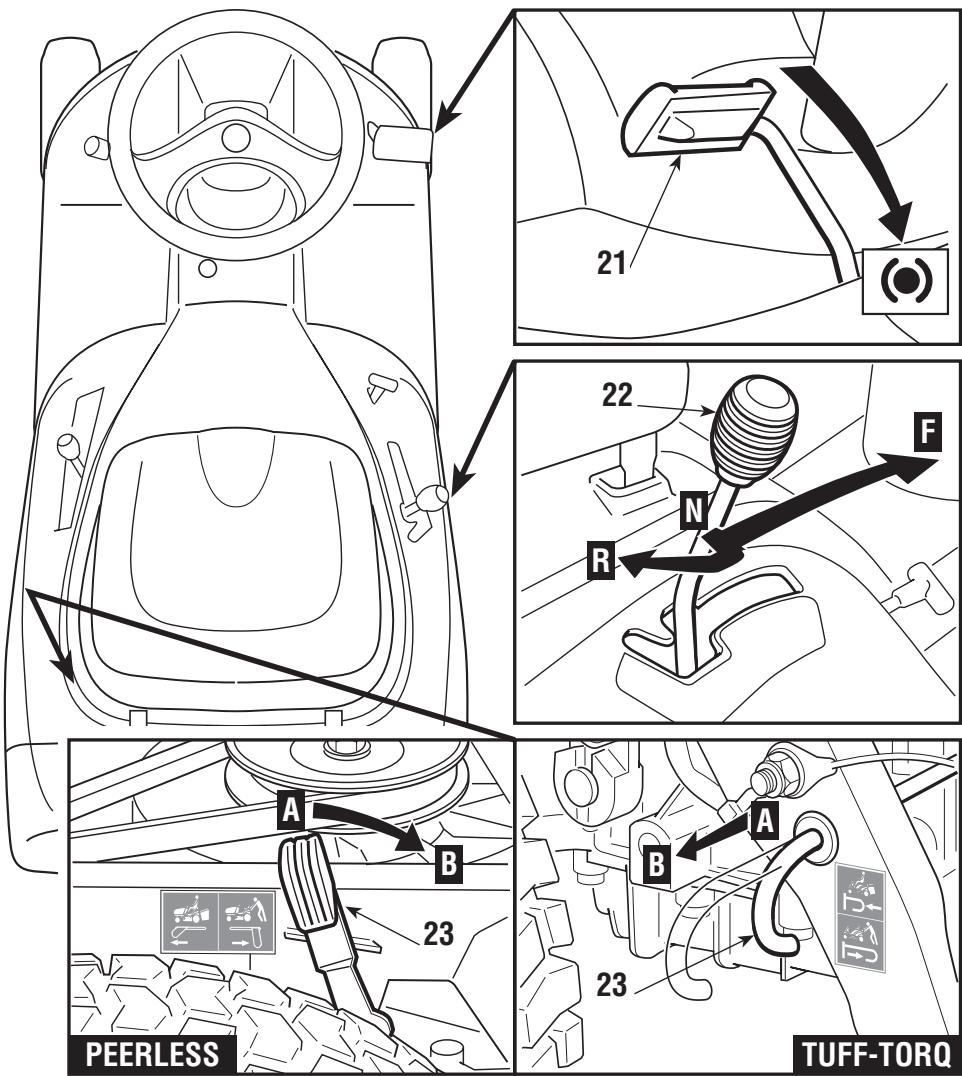
(21) is pressed the lever automatically returns to the «N» (neutral) position. It can also be moved there manually even without pressing the brake.
IMPORTANT
When the parking brake (3) is engaged the speed change
lever is locked in the «N» position and cannot be moved until the parking brake and the pedal have been released.
23. LEVER TO RELEASE THE HYDROSTATIC DRIVE
This lever has two positions shown on the plate:
Position «A» = Drive engaged: for all operating conditions, when moving and during cutting;
Position «B» = Drive released: considerably reduces the effort required for moving the machine manually, when the engine is not running.
IMPORTANT
To avoid damaging the transmission unit, this operation
must be carried out only when the engine has stopped with the lever (22) at position “N”.
5. HOW TO USE THE MACHINE
DANGER!
REMEMBER THAT THE USER IS ALWAYS RESPONSIBLE
FOR DAMAGE AND INJURIES TO OTHERS. Before using the machine, read the safety requirements shown in chapter 2, paying particular attention to driving and cutting on slopes. It is the user's responsibility to assess the potential risk of the area where work is to be carried out, as well as to take all the necessary steps to ensure safe working, particularly on slopes or rough, slippery and unstable ground. This machine must not be used on slopes greater than 10^ (17%).
WARNING!
If the machine is likely to be used mostly on sloping
ground (max. 10^ ), fit counterweights (supplied on request) to the front part of the frame to improve stability at the front and reduce the chance of tipping up.
IMPORTANT
All references regarding the positions of controls are shown
in chapter 4.
5.1 DIRECTIONS BEFORE STARTING
SEAT ADJUSTMENT
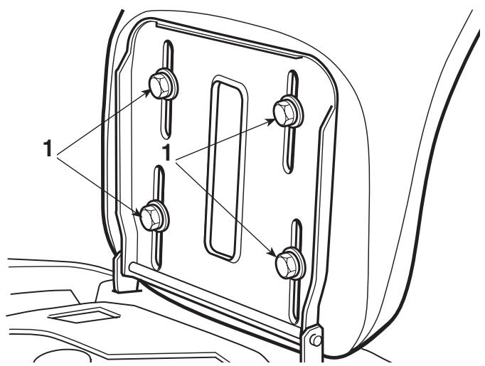
The seat is held by four screws (1) which have to be loosened for changing the position of the seat which is done by sliding it along the slots in the base.
When you have got in a comfortable position, fully tighten the four screws.
REFUELLING
NOTE
The oil and fuel to use are indicated in the engine booklet.
To reach the oil level dipstick, lift up the seat and open the hatchway beneath.
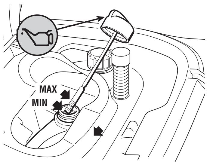
With engine stopped, check its oil level which must be between the MIN and MAX marks on the dipstick.
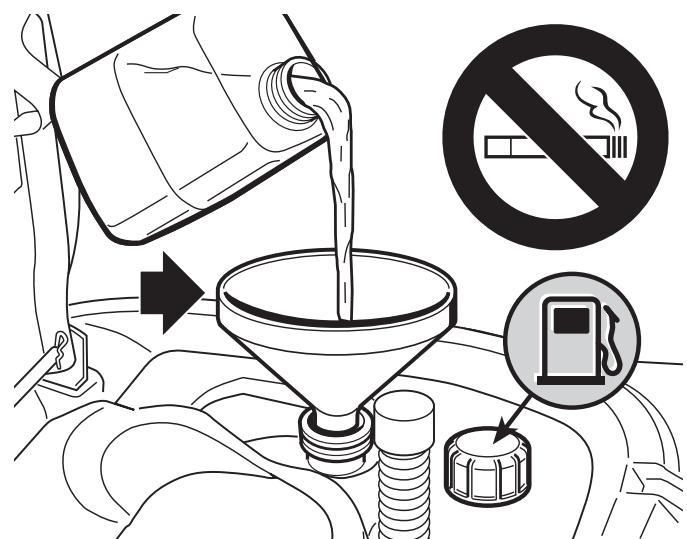
Refuel using a funnel, but do not completely fill the tank.
The tank's capacity is about 4 litres.
DANGER!
Refuelling should be carried out in an open or well venti-
lated area with engine stopped. Always remember that petrol fumes are inflammable. DO NOT TAKE FLAMES TO THE TANK MOUTH TO VERIFY ITS CONTENTS AND DO NOT SMOKE WHEN REFUELLING.
IMPORTANT
Do not drip petrol onto the plastic parts to avoid ruining
them. In the event of accidental leaks, rinse immediately with water.
TYRE PRESSURE
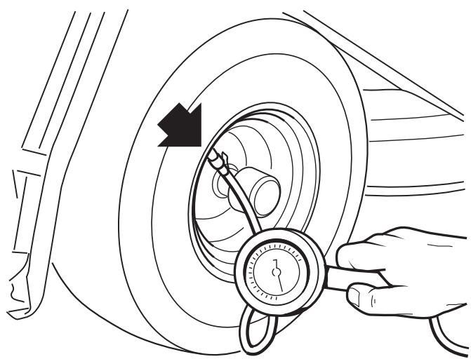
Having the correct tyre pressure is essential for keeping the cutting deck horizontal and thus achieving uniform mowing. Unscrew the valve protection cap and connect the valves to a compressed air line with a gauge.
Pressures are:
FRONT
1.5 bar
REAR
1.0 bar
FITTING THE PROTECTION AT THE EXIT (GRASS-CATCHER OR STONE-GUARD)
WARNING!
Never use the machine
without having fitted the exit protection!
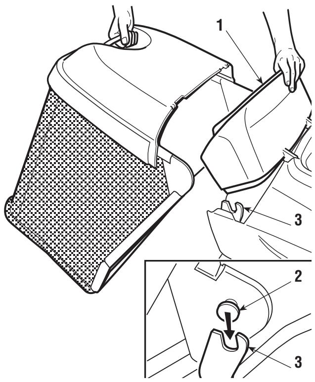
Lift the removable cover (1) and hook on the grass-catcher by inserting the two pivots (2) into the slots on the two supports (3).
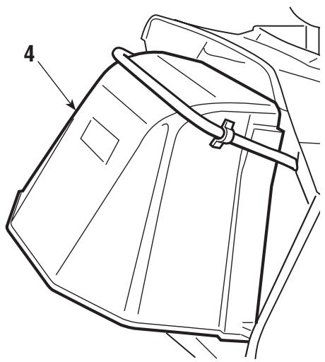
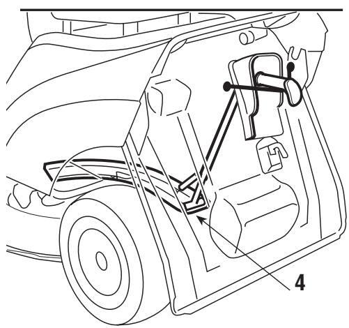
If you want to work without using the grass-catcher, a stone-guard kit (4) is available on request which is fitted as shown in the figure.
WARNING!
There is a micro-switch
which stops the engine or prevents starting when the blade is engaged if either the grass-catcher or stone-guard is not in position. IT IS VERY DANGEROUS TO TAMPER WITH OR LIMIT THE EFFECTIVENESS OF THIS DEVICE!
CHECKING THE SAFETY SYSTEMS
Every time before using, check that the safety systems
are working properly. To do so, simulate the various situations of usage shown in the table on page 26, making sure that the correct result is achieved for each situation.
Make sure that the machine's braking capacity is adequate for the conditions of usage. Avoid starting the machine if you have doubts on the brake efficiency. If necessary, adjust the brake and if you still have doubts on its efficiency, consult a Licensed Service Centre.
BLADE CHECK
Check that the blade is sharpened properly and firmly fixed to the hub. A badly sharpened blade pulls at the grass and causes the lawn to turn yellow.
5.2 STARTING AND MOVING
STARTING
DANGER! All starting operations have to be effected in an open or well ventilated area! ALWAYS REMEMBER THAT EXHAUST GASES ARE TOXIC!
Before starting the engine:
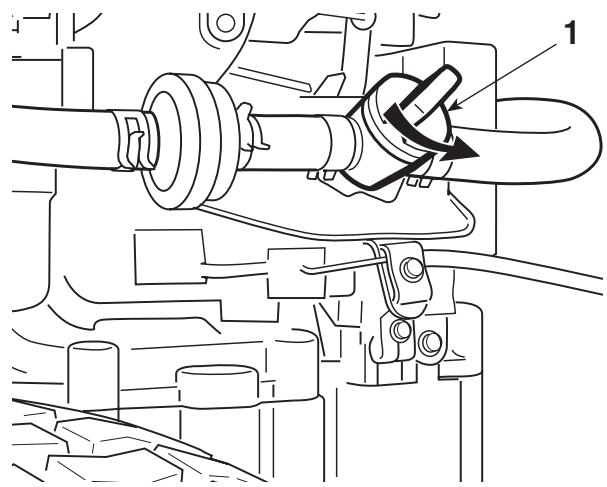
- open the fuel stopcock (1) (where supplied), which you can reach from the left-hand rear wheel arch;
- put the gear lever ( for mechanical drive models) or the speed change lever pedal (
for hydrostatic drive models) into neutral ( N) ;
- disengage the blade;
- on slopes, engage the parking brake:
Afterwards:
- put the accelerator lever to «CHoke», as shown on the label, if the engine is cold. If the engine is already warm, put the lever between «SLOW» and «FAST»;
- put in the key and turn to «ON» to make electrical contact, then turn to «START» to start the engine. Release once the engine has started.
When the engine is running, put the accelerator into the «SLOW» position.
NOTE
Should you have difficulties in starting do not continue to
use the starter motor for a long time as this can run down the battery or flood the engine. Turn the key to the «OFF» position, wait for a few seconds and then repeat the operation. If the malfunction continues, refer to chapter «7» of this manual and to the engine booklet.
IMPORTANT
Always bear in mind that the safety devices prevent the
engine from starting if safety requirements have not been met (see page 26).
The pilot lamp will begin flashing if the key is held in the «START» position when the safety devices have been activated.
MOVING WITHOUT MOWING
WARNING!
The machine has not been approved for use on public
roads. It has to be used (as indicated by the highway code) in private areas closed to traffic.
NOTE When moving the machine, the blade must be disengaged and the cutting deck put at its highest position (position «7»).
For mechanical drive models:
Put the accelerator control between the «SLOW» and «FAST» positions, and the gear change lever in the 1st speed position.
Keep the pedal pressed down and disengage the parking brake. Slowly release the pedal which will turn from «brake» to «clutch», thus operating the rear wheels.
The pedal has to be released gradually as a sudden engagement may cause tipping up and loss of control of the vehicle.
Gradually reach the desired operating speed using the accelerator and gear lever. To change the gear speed the clutch must be used pushing the pedal down half way.
For hydrostatic drive models:
Put the accelerator control between the «SLOW» and «FAST» positions. Press the brake pedal to disengage the parking brake and release the pedal.
Move the speed change lever in the «F» direction and go to the required speed by using the lever and the accelerator.
The lever must be moved gradually as a sudden engagement of drive to the
- wheels may cause tipping and loss of control of the machine.
BRAKING
For mechanical drive models:
- To brake, first reduce the speed on the accelerator to avoid overloading the
- brake assembly and then push the pedal down fully.
For hydrostatic drive models:
- To brake, press the brake pedal which will simultaneously make the speed
- change lever return to the «N» position.
REVERSE
For mechanical drive models:
The machine MUST be stopped before reverse can be engaged. Push down
the pedal until the machine stops and then insert reverse by moving the lever
- sideways and putting it into position «R». Gradually release the pedal to
- engage the clutch and then begin moving in reverse.
For hydrostatic drive models:
The machine MUST be stopped before reverse can be engaged. When the
- machine is stopped, start the reverse movement by putting the speed change
lever in the «R» direction.
5.3 GRASS CUTTING
ENGAGING THE BLADE AND FORWARD MOVEMENT
When you have reached the area to be mowed,
- put the accelerator into the «FAST» position;
-
engage the blade by putting the lever into position «B»;
-
to begin moving, operate the speed regulation controls taking care to release the pedal very gradually and with particular caution as already described.
Engage the blade with the cutting deck in the highest position, and then gradually lower to the height required. To achieve good collection and even cutting of the grass, choose a forward speed to suit the quantity of grass to be cut (height and density) and the lawn's humidity, in line with the following indications (for mechanical drive models):
- High and dense grass
- wet lawn 1st speed
- Average condition grass 2nd - 3rd speed
- Low grass - dry lawn 4th speed
NOTE
The fifth gear is solely for moving from one area to another
on horizontal surfaces.
For hydrostatic drive models the speed has to be adapted to the condition of
the grass in a gradual and progressive way by moving the speed change lever.
The speed should always be reduced if you note a reduction in engine speed, since a forward speed that is too fast will not cut the grass well.
Disengage the blade and put the cutting deck in the highest position whenever you need to get past an obstacle.
CUTTING HEIGHT ADJUSTMENT
The height is adjusted by moving the lever with 7 height positions.
HOW TO OBTAIN A GOOD CUT
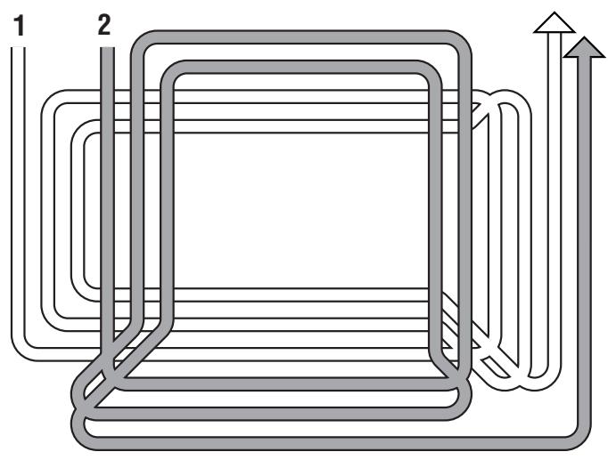
- The lawn's appearance will be best if you cut in alternate directions, always at the same height.
- If the collector system blocks up you should reduce the forward speed as it
could be too high for the lawn conditions.
If this does not solve the problem, it is probably due to unsharpened cutting edges or the wings on the blade having become deformed (see chapter 7).
- If the grass is very tall it should be mowed twice - once at the maximum cutting height, and perhaps reducing the cutting width, followed by a second cut at the required height.
- Be very careful when mowing near bushes or kerbs which could alter the horizontal position of the cutting deck or damage its edge or the blade.
SLOPES
Complying with the slope limits already mentioned, lawns on a slope have to mowed moving up and down and never across them, taking great care when changing direction that the first wheels do not hit obstacles (such as stones, branches, roots, etc.), that may cause the machine to slide sideways, roll over or otherwise cause loss of control.
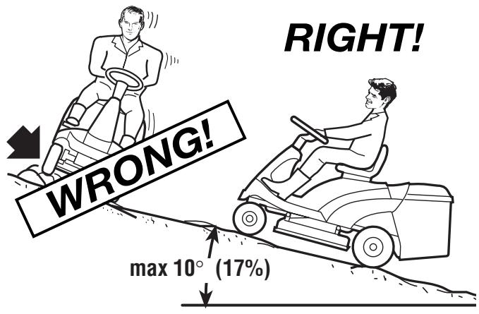
DANGER!
REDUCE SPEED BEFORE ANY CHANGE OF DIRECTION
ON SLOPES and always engage the parking brake before leaving the machine stopped and unattended.
WARNING!
Take care when beginning forward movement on slop-event the risk of tipping up.
For mechanical drive models:
DANGER!
Never ride the machine on slopes in neutral gear or
with the clutch out! Always engage a low gear before leaving the machine stopped and unattended.
For hydrostatic drive models:
Move on slopes with the speed change lever in the «N» position, (to take advantage of the hydrostatic unit's braking effect) and then further reduce the speed using the brake, if necessary.
DANGER!
Never use reverse for reducing speed going downhill.
Control of the machine could be lost, particularly on slippery surfaces.
This operation can only be
done with the blade disengaged, otherwise the engine stops.
When the grass-catcher is full an audible warning is given. STOP FORWARD MOVEMENT, in order not to block the collector channel, and disengage the blade which will stop the audible signal. Empty the grass-catcher by lifting it using the handle.
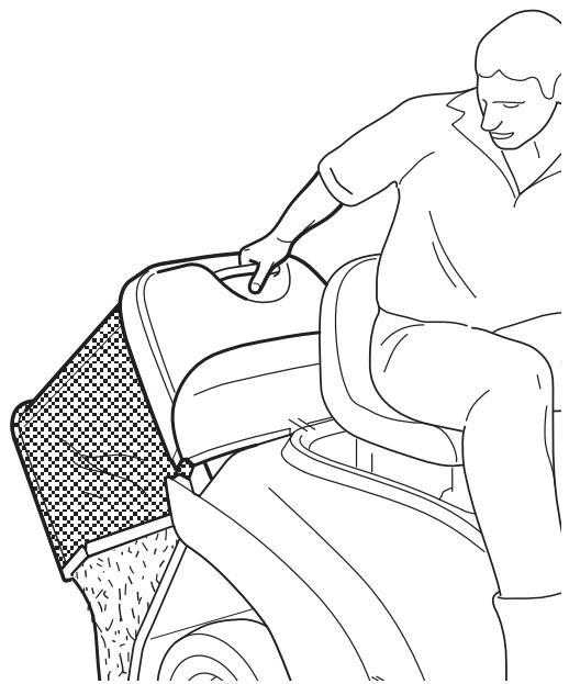
NOTE
At times the audible warning
may be heard on engaging the blade even when the grass-catcher has been emptied. This is due to grass cuttings left on the sensor of the micro-switch. To stop the signal, either remove the remaining grass or disengage the blade and then immediately engage it again.
EMPTYING THE COLLECTOR CHANNEL
Cutting very tall or wet grass, particularly at too high a speed, can cause the collector channel to become blocked. Should this happen, it will be necessary to:
- stop forward movement, disengage the blade and stop the engine;
- take off the grass-catcher or stone-guard;
- remove the accumulated cuttings going in through the exit of the collector channel.
SUMMARY OF THE MAIN CONDITIONS WHEREBY THE SAFETY DEVICES PERMIT OR STOP WORK
The safety devices work in two ways:
- by preventing the engine from starting if all the safety requirements have not been met;
- stopping the engine if even just one of the safety requirements is lacking.
a) To start the engine it will be necessary that:
- the transmission is in "neutral";
- the blade is not engaged;
- the operator is seated or the parking brake is engaged.
b) The engine stops when:
- the operator leaves his seat when the blades are engaged;
- the operator leaves his seat when the transmission is not in "neutral";
- the operator leaves his seat with the transmission in "neutral" but without engaging the parking brake;
- the grass-catcher is lifted or the stone-guard is removed when the blades are engaged;
- the parking brake is engaged without disengaging the blade.
The table below shows various operating conditions, highlighting why the safety device shuts down the engine.
| OPERATOR | GRASS-CATCHER | BLADE | TRANSMISSION | BRAKE | ENGINE |
| A) WHEN STARTING (Key in «START» position) | |||||
| Sitting | Uninfluentia | Disengaged | 1....5 - F/R | Engaged | Does NOT start |
| Sitting | Uninfluentia | Engaged | «N» | Engaged | Does NOT start |
| Absent | Uninfluentia | Disengaged | «N» | Disengaged | Does NOT start |
| B) WHEN CUTTING (Key in «ON» position) | |||||
| Absent | YES | Engaged | Uninfluentia | Engaged | Stops |
| Absent | Uninfluentia | Disengaged | 1....5 - F/R | Disengaged | Stops |
| Absent | YES | Disengaged | «N» | Disengaged | Stops |
| Sitting | NO | Engaged | Uninfluentia | Disengaged | Stops |
| Sitting | YES | Engaged | Uninfluentia | Engaged | Stops |
CARD PROTECTION DEVICE
The electronic card has a self-resetting protector which breaks the circuit if there is a fault in the electrical system. It results in the stopping of the engine and is signalled by the pilot lamp turning off.
The circuit automatically resets after a few seconds but the cause of the fault should be ascertained and dealt with to avoid re-activating the protection device.
IMPORTANT
To avoid activating the protection device:
- do not reverse the cables on the battery terminals;
- do not use the machine without its battery or damage may be caused to the charging regulator;
- be careful to not cause short-circuits.
END OF MOWING
When you have finished mowing, disengage the blade and ride the machine with the cutting deck in the highest position.
Stop the machine, engage the parking brake and turn off the engine by turning the ignition key to «OFF».
When the engine is stopped, close the fuel cock (1) (where fitted).
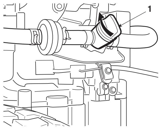
WARNING!
To avoid backfire, put the accelerator in the «SLOW» seconds before stopping the engine.
WARNING!
Always take out the ignition key if leaving the machine
unattended!
IMPORTANT
To keep the battery charged, do not leave the key in the box. Then the engine is not running.
5.4 CLEANING AND STORAGE
CLEANING
After each mowing, clean the outside of the machine, empty the grass-catcher and shake it to remove residual grass and earth.
Clean the plastic parts of the body with a damp sponge using water and detergent, taking care not to wet the engine, the electrical parts or the electronic card located under the dashboard.
IMPORTANT
Never use hose-nozzles or harsh detergents for cleaning the
body and engine!
WASHING THE INSIDE OF THE CUTTING DECK
The machine has to be put on firm ground with the stone-guard or grass-catcher in position. Washing the inside of the cutting deck and the collector channel is done by attaching a water hose to the connector (1) and running water through for a few minutes, with:
- the operator seated;
- the engine running;
- the drive in neutral;
- the blade engaged.
When washing, the cutting deck should be in the fully lowered position. Take off the grass-catcher, empty and rinse it, and then put it in a position to assist quick drying.
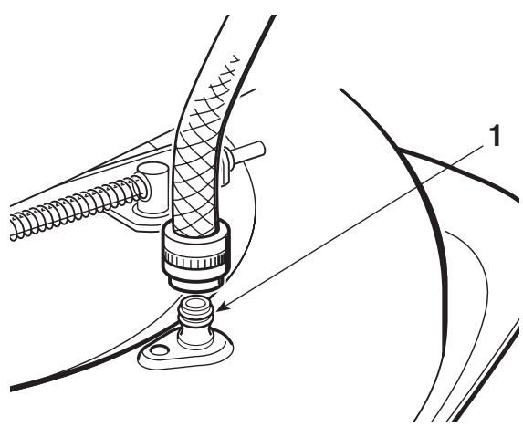
STORAGE AND INACTIVITY FOR LONG PERIODS
If the machine is likely to be unused for a long period (more than 1 month), disconnect the cables from the battery and follow the instructions in the engine manual. Lubricate all joints as directed in chapter 6.
WARNING!
Carefully remove any dry
grass cuttings which may have collected around the engine or silencer to prevent their catching fire the next time the machine is used!
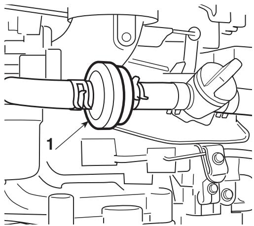
Empty the fuel tank by disconnecting the tube situated at the inlet of the fuel filter (1) and follow the instructions in the engine booklet.
IMPORTANT
The battery must be kept in a cool and dry place. Before a
long storage period (more than 1 month), always charge the battery, and then recharge before using again (chapter 6).
The next time the machine is used, check that there are no fuel leaks from the tubes, fuel cock or carburettor.
6. MAINTENANCE
WARNING!
Before cleaning, maintenance or repair work, take out and read the relevant instructions. Wear suitable clothing as
IMPORTANT
Never get rid of used oil, fuel or other pollutants in unautho
rised places!
ACCESS TO MECHANICAL PARTS
Lift the engine cover (1) to access the engine and mechanical parts below it.
To do so:
- put the machine on level ground, bring the cutting deck into the highest position and put blocks (2) of around 65 - 70 ~mm beneath the edge to hold up the deck during the following stages.
For mechanical drive models:
- engage the parking brake;
For hydrostatic drive models:
-
put the drive release lever into the «ENGAGED» position (see chap. 4, n° 23), since it is necessary for the parking brake to be disengaged to ensure that the speed change lever has enough movement;
-
remove the grass-catcher or stone-guard;
- unscrew the knob on the lever (3) and put the lever into neutral «N» (For mechanical drive models), or in «R» (For hydrostatic drive models);
- open the access hatch (4) and unscrew the nut (5) with a 13 mm spanner;
- release the lever (6) so that the deck rests on the blocks and keep the lever
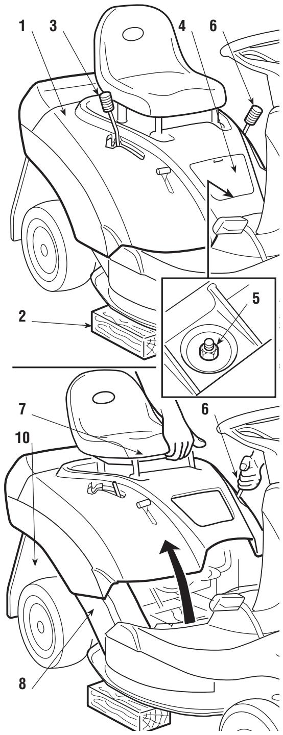
moved sideways so that it is not in any of the notches. Hold the base of the seat (7) and tip the cover back.
On closing:
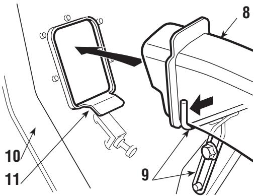
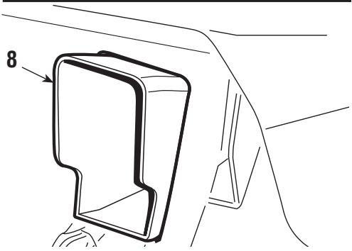
- check that the collector channel (8) is properly fitted onto its support (9) and resting on the right-hand guide;
- put the lever (3) into the «R» position and lower the cover (1) to the height of the levers (3) and (6);
- first put the lever (6) into its housing followed by lever (3). Lower the cover in line with the fastening screw.
WARNING!
When the cover (1) has been lowered check that:
- he channel exit (8) is correctly lined up with the opening in the rear plate (10) and that it is resting on the support (11).
Then:
- fully tighten the fixing nut (5);
- put the lever (6) into the notch at position «7»;
- take the blocks (2) away, and reassemble the knob on the lever (3) and the access hatch (4).
ENGINE
Follow the instructions in the engine booklet.
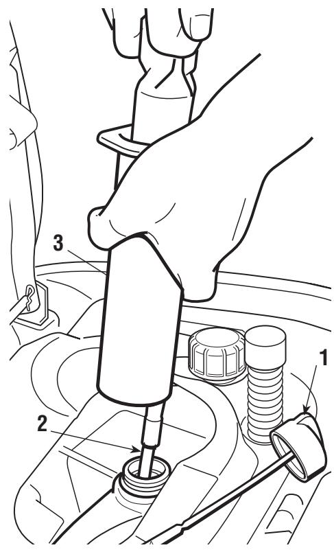
Drain the engine oil by unscrewing the oil fill plug (1) and using the syringe supplied.
Fit the pipe (2) onto the syringe (3) and insert it right into the hole. Drain all the engine oil, repeating if necessary until there is no oil left in the engine.
REAR AXLE
These are permanently lubricated with grease that does not need changing.
BATTERY
To ensure long life to the battery it is essential to keep it carefully maintained.
The machine battery must always be charged:
- before using the machine for the first time after purchase;
- before leaving the machine for a prolonged period of disuse;
-
before starting up the machine after a prolonged period of disuse.
-
Carefully read and comply with the procedure for recharging described in the booklet coming with the battery. If the procedure is not followed or the battery is not charged, irreparable damage could be caused to the elements inside the battery.
- A flat battery must be recharged as soon as possible.
IMPORTANT
Recharging must be done using a battery charger at con-
stant voltage. Other recharging systems can irreversibly damage the battery.
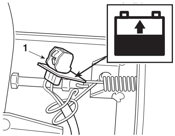
The machine has a connector (1) for recharging, to be connected to the corresponding connector of the special "CB01" maintenance battery-charger supplied (if included) or available on request (chapter 8).
IMPORTANT
This connector must only
be used for connection to the “CB01” maintenance battery-charger. For its use:
- follow the instructions given in the relative instruction booklet,
- follow the instructions given in the battery booklet.
REPLACING A FUSE
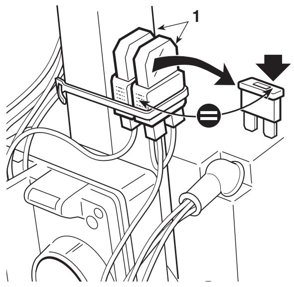
The machine is fitted with fuses (1) with different capacities and functions. Specifically:
- 10 ~A fuse = protects the main and power circuits of the electronic board. When it blows, the machine stops and the dashboard light
switches off.
- 25 A fuse = protects the battery charger circuit. When it blows, the battery gradually runs out and the machine will have problems starting.
The fuse capacity is indicated on the fuse.
IMPORTANT A blown fuse must always be replaced by one of the same type and ampere rating, and never one of a different rating.
If you cannot find the cause of the protection device's activation, consult a Licensed Service Centre.
CHANGING WHEELS
Stop the machine on a flat surface and put blocks under a load-bearing part of the frame on the side that the wheel is to be changed.
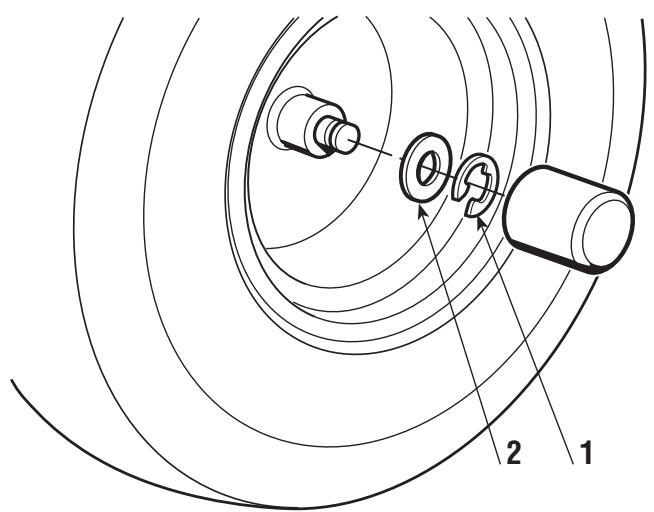
The wheels are held by a snap ring (1) which can be taken off with a screwdriver.
The rear wheels are directly coupled to the axle shafts and fastened by a key that forms part of the wheel's hub.
Before re-fitting a wheel, smear some grease on the axle and carefully re-fit the snap ring and washer (2).
NOTE Should you substitute one or both rear wheels, ensure that they are of the same diameter, and check that cutting deck is horizontal to prevent an uneven cut.
CHANGING AND REPAIRING TYRES
Tyres are of the «Tubeless» type and therefore all puncture repairs will have to be carried out by a tyre-repair expert in accordance with the methods for this kind of tyres.
CHANGING BELTS
The motion from the engine to the rear axle and from the motor to the blade is obtained by two "V" belts, whose duration largely depends on how the machine is used.
Replacing belts is quite complicated because of dismantling and adjustments and must only be carried out by a Licensed Service Centre.
NOTE
Belts must always be replaced as soon as they are seen to USE MANUFACTURER'S Genuine SPARE BELTS!
CUTTING DECK ADJUSTMENT
The cutting deck should be properly adjusted to obtain a good cut. Height adjustments to the cutting deck are made through three linkages.
Such adjustments are to be made on a flat surface after having ensured that the tyre pressures are correct.
NOTE
For achieving good
results from cutting, the front part should always be 2 - 4 mm lower than the rear.
To adjust the cutting deck so that it is parallel with the ground:
- put one 26 ~mm block (1) under the edge of the deck and one 32 ~mm block (2) under the rear edge, then put the lifting lever into the notch at position «1»;
- loosen the nuts (3 - 5 - 7) and the locknuts (4 - 6 - 8) so that the deck is resting firmly on the blocks;
- turn the nut (3) until the right-hand rear part of the deck starts to rise, and then tighten the relative locknut (4);
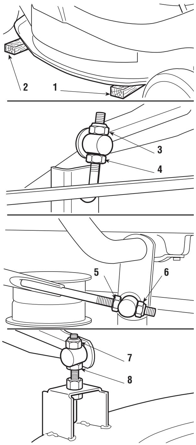
- screw down the nut (5) on the rod until the right-hand front part of the deck begins to rise, and then tighten the relative locknut (6);
- screw the nut (7) on the front left support until the deck in that area begins to rise, and then tighten the nut (8)
If you are unable to get the cutting deck parallel, consult a Licensed Service Centre.
BRAKE ADJUSTMENT
The adjustment will need to be made while the parking brake is engaged.
For mechanical drive models:
For hydrostatic drive models (Peerless):
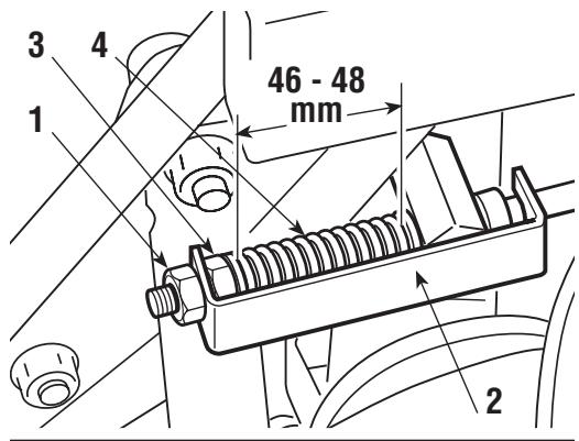
- Loosen the nut (1) which holds on the bracket (2)
and turn the nut (3) until the length of the spring
(4) is 46 - 48 ~mm inside the washers. - When the adjustment has been made, tighten the
- nut (1).
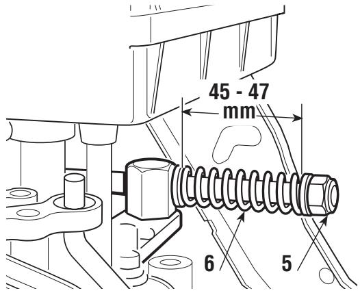
For hydrostatic drive models (Tuff-Torq):
- Turn the nut (5) until the length of the spring (6) is
45 - 47 mm inside the washers.
IMPORTANT
Do not screw to below these
values to avoid overloading the brake unit.
ADJUSTING DRIVE ENGAGEMENT
For mechanical drive models:
If you should notice that forward drive power
- has dropped, you can adjust the regulating
screw (1) which is accessible through the
- hatchway beneath the seat. Undoing the
screw and then lengthening the spring (2) will
- increase the drive ability.
The best length for the spring is 86 mm mea
- sured from the outer ends of the spring. Once the adjustment has been made,
- tighten the locknuts (3). Excessive spring tension may cause too sudden
- engagement of the clutch, resulting in the machine tipping up.
ADJUSTMENT TO BLADE ENGAGEMENT AND BRAKE
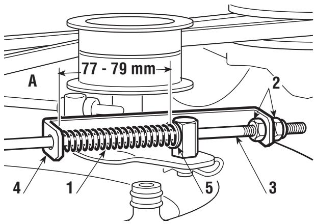
If there seem to be problems in engaging the blade or the time for stopping after disengagement is over 5 seconds, adjust the spring tension (1).
To make this adjustment, loosen the nuts (2) and screw or unscrew them on the control rod (3) in order to obtain a distance of 77- 79 mm between the bracket (4) and the inside
of the washer (5), with the blade engaged and the cutting height adjustment lever at position “1”. When the adjustment has been made, screw the nuts (2) back on.
For hydrostatic drive models:
The speed change lever has a clutch device which keeps it in the position selected during forward movement and which returns the lever to neutral when brake is operated.
If the lever does not stay in position during working and has difficulty in returning to neutral, the adjuster nut (1) will need to be registered to restore normal functioning.
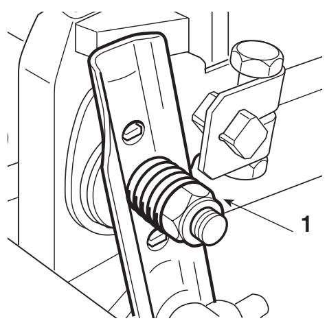
Check that the blade is sharpened properly and firmly fixed to the bracket.
- A badly sharpened blade pulls at the grass and causes the lawn to turn yellow.
- A loose blade causes unusual vibrations and can be dangerous.
WARNING!
All operations on the blade (dismantling, sharpening,
balancing, remounting and/or replacing) require a certain familiarity and special tools. For safety reasons, go to a specialized centre if you do not have the right tools or experience.
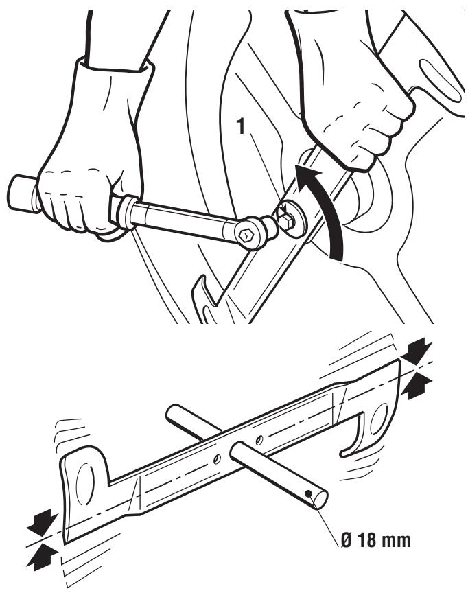
To remove the blade, hold it firmly wearing strong gloves and undo the central screw (1).
Sharpen the two cutting edges using a medium grade grinding wheel and check the balance by holding the blade up with a round 18 ~mm diameter bar inserted in the central hole.
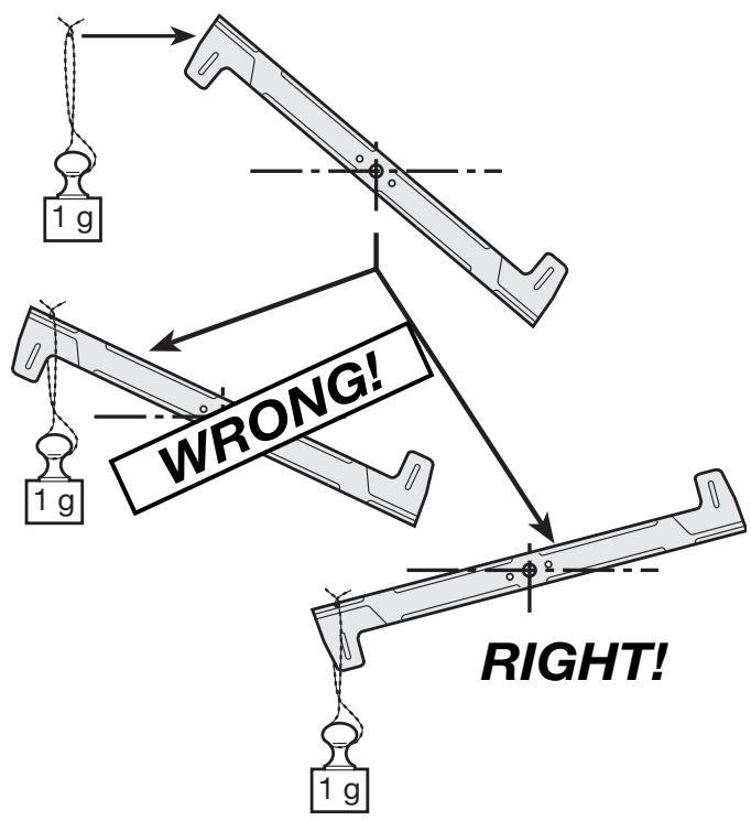
To ensure that it works properly without unusual vibrations any imbalance between the two parts of the blade must be below one gram.
This can be easily ascertained by putting a one gram weight on the lightest end of the blade. If it tends to go below the balanced position it means that the balance is correct, while if it stays up then the other end will have to be made lighter.
WARNING!
A damaged or bent
blade must always be replaced; never try to repair it! ALWAYS USE MANUFACTURER'S Genuine SPARE BLADES !
WARNING!
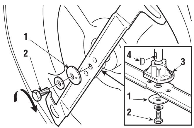
When re-fitting the
blade, always follow the indicated sequence, making sure that the blade's wings are facing towards the interior of the cutting deck and that the concave part of the cup spring (1) is pressing against the blade. Tighten the fixing screw (2) using a torque wrench set to 45-50 Nm. If the shaft hub (3) came off when dismantling the blade, make sure that the key (4) is firmly in its right position.
GUIDE TO SCHEDULED MAINTENANCE
This table is to help you maintain your machine's safety and performance. It shows the main maintenance and lubrication work, indicating the frequency with which it should be carried out.
To the right of each one there is a box where you can write the date or after how many hours of operation the work was carried out.
| WORK | HOURS | DATE OR N° OF HOURS | ||||||
| 1. MACHINE | ||||||||
| 1.1 Check of tight fixing and sharpness of blade 25 | ||||||||
| 1.2 Blade replacement 100 | ||||||||
| 1.3 Check of the transmission belt 25 | ||||||||
| 1.4 Transmission belt replacement 2) - | ||||||||
| 1.5 Checking the blade drive belt 25 | ||||||||
| 1.6 Blade drive belt replacement 2) - | ||||||||
| 1.7 Check and adjustment of brake 10 | ||||||||
| 1.8 Check and adjustment of drive 10 | ||||||||
| 1.9 Check blade engagement and brake 10 | ||||||||
| 1.10 Check of tight fixing of all the elements 25 | ||||||||
| 1.11 General lubrication 3) 25 | ||||||||
| 2. ENGINE 1) | ||||||||
| 2.1 Engine oil change ...... | ||||||||
| 2.2 Check and cleaning of air filter ...... | ||||||||
| 2.3 Air filter replacement ...... | ||||||||
| 2.4 Check of fuel filter ...... | ||||||||
| 2.5 Fuel filter replacement ...... | ||||||||
| 2.6 Check and cleaning of spark plug points ...... | ||||||||
| 2.7 Replacement of spark plug ...... | ||||||||
1) See the engine booklet for a full list and methods of work.
2) If worn, immediately contact a Licensed Service Centre for the replacement.
3) General lubrication should be carried out whenever the machine is to be left unused for a long period.
LAYING ON ITS SIDE
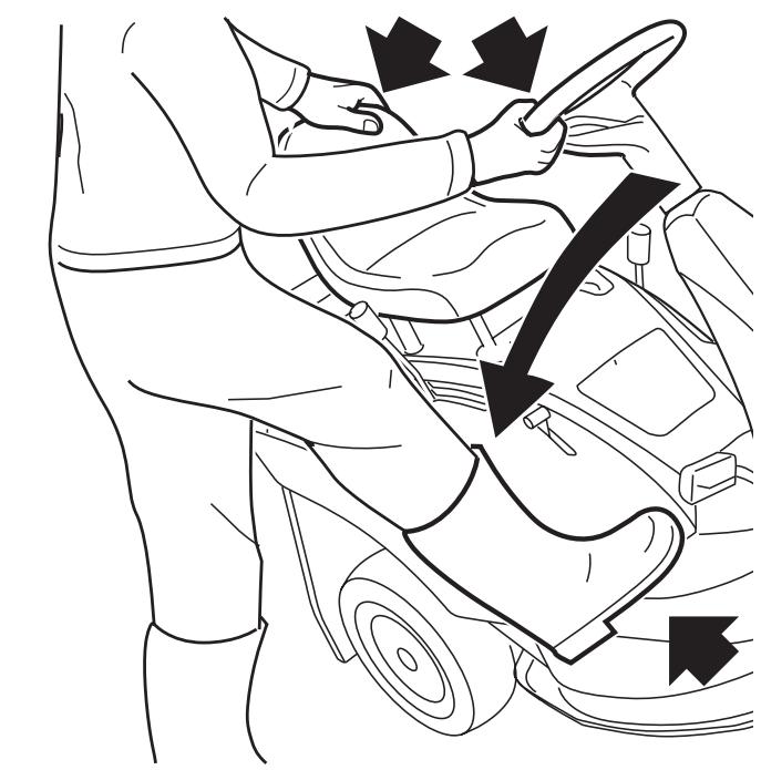
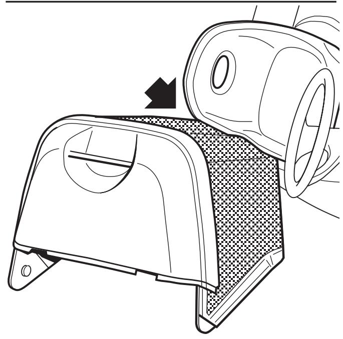
In order to easily reach beneath the machine, it can be turned onto its side after having removed the grass-catcher and completely emptied the fuel tank.
Having put the machine onto a firm and flat surface, engage the parking brake, put the cutting deck into position «7», firmly grip the steering wheel and the seat, and turn the machine onto its right hand side so that it rests on the grass-catcher (as shown), taking care not to damage plastic parts.
DANGER!
Make sure that the
machine is stable before starting any work and do not carry out work that may cause it to fall.
7. TROUBLESHOOTING
| PROBLEM | SITUATION | LIKELY CAUSE | SOLUTIONS |
| 1. Pilot lamp off | Key is in «ON» position, engine stopped | Electronic card in safety alert, due to: | Put the key in the «OFF» position and look for the cause of the problem: |
| - badly connected battery | - check connections | ||
| - completely flat battery or eroded battery plates | - recharge battery | ||
| - battery terminals crossed | - connect properly | ||
| - fuse blown | - replace fuse (10 A) | ||
| - badly earthed | - check connections | ||
| - electronic card wet | - dry by air | ||
| - earthed micro-switches | - check connections | ||
| 2. Starter motor not working | Key in «START» position and pilot lamp on | - insufficiently charged battery | - recharge battery (if the problem continues, consult a Licensed Service Centre) |
| - battery charger fuse blown | - replace fuse (25 A) | ||
| - badly earthed | - check connections | ||
| Key in «START» position and pilot lamp flashing | - you are not ready for starting | - Check that the conditions allowing the start are met (see page 26/a) | |
| 3. Engine does not start | Key in «START» position | - no fuel supply | - check fuel level |
| - open fuel stop-cock (where fitted) | |||
| - check the wiring of the fuel open command (where fitted) | |||
| - check fuel filter | |||
| - faulty ignition | - check that spark plugs caps are firmly fitted | ||
| - check that the electrodes are clean and have the correct gap | |||
| 4. Starting is difficult or the engine runs erratically | Key in «ON», engine running | - fuel fault | - clean or replace the air filter - flush out the float chamber - empty fuel tank and refill with new fuel - check and, if necessary, replace fuel filter |
| 5. Weak engine performance during cutting | Key in «ON», engine running | - forward speed too high in relation to cutting height | - reduce the forward speed and/or raise the cutting deck |
| 6. The engine stops but the light flashes | Key in «ON», engine running | - the safety devices cut in | - check that the conditions allowing starting are met (see page 26/b) |
| 7. The engine stops and the light goes off | Key in «ON», engine running | Electronic card in safety alert, due to: - earthed micro-switches - flat battery - overload caused by the charge regulator - badly connected battery (poor contact) - engine badly earthed | Put the key in the «OFF» position and look for the cause of the problem: - check connections - recharge battery - contact a Licensed Service Centre - check battery connections - check engine earth connection |
| 8. The engine stops but the light stays on | Key in «ON», engine running | - problems in the engine | - contact a Licensed Service Centre |
| 9. Uneven cut and poor grass collection | Key in «ON», engine running | - cutting deck not parallel to the ground - blade cutting badly | - check tyre pressures - re-align the cutting deck to the ground - check that the blade is fitted properly - sharpen or replace the blade - check the tension of the belt |
| - forward speed too high compared to height of grass | - reduce forward speed and/or raise the cutting deck | ||
| - wait for grass to dry | |||
| - collector channel is obstructed | - remove the grass-catcher and empty the collector channel | ||
| - cutting deck full of grass | - clean the cutting deck | ||
| 10. Unusual vibrations while working | Key in «ON», engine running | - the blade is imbalanced | - balance or replace the damaged blade |
| - blade loose | - check that the blade is firmly fitted | ||
| - fixing screws loose | - check and tighten all the fixing screws of engine and the machine | ||
| - cutting deck is obstructed | - remove the grass-catcher, empty the collector channel and clean the inside of the cutting deck |
If problems continue after having carried out these operations, contact a Licensed Service Centre.
WARNING!
Do not take on complicated repair work if you don't
have the necessary equipment and the technical knowledge. The guarantee is automatically revoked and the manufacturer declines all responsibility for any repairs which are badly done.
8. ACCESSORIES ON REQUEST
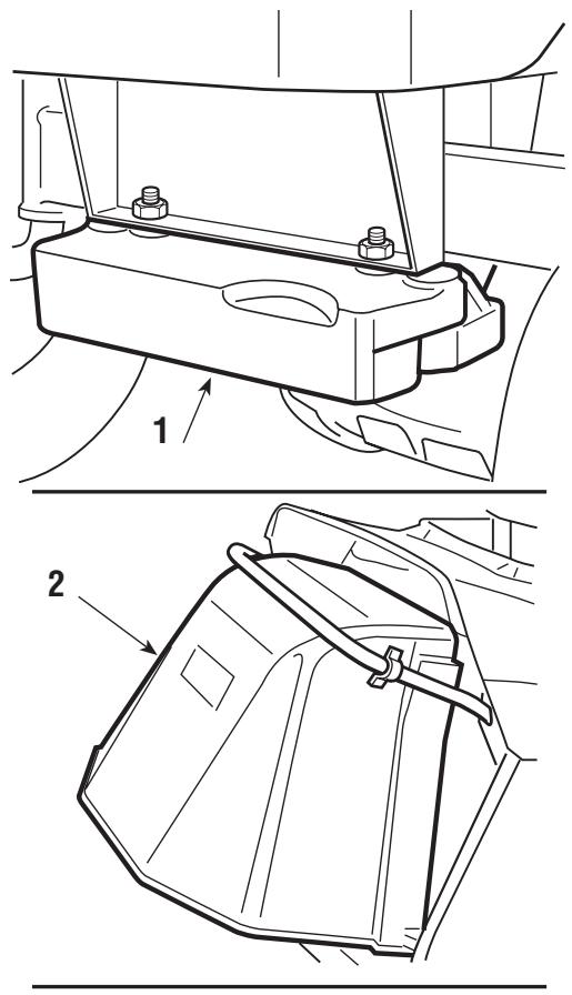
1. FRONT COUNTERWEIGHTS
These improve stability at the front of the machine, particularly when being used on ground which is mostly sloping.
2. STONE-GUARD KIT
For use in place of the grass-catcher when the cuttings are not to be collected.
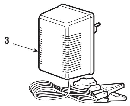
3. "CB01" MAINTENANCE BATTERY-CHARGER
This makes it possible to keep the battery in good working order when the machine is in storage, guaranteeing an optimum level of charge and a longer life to the battery.
4. KIT FOR "MULCHING"
It finely chops the grass cuttings and leaves them on the lawn, instead of collecting them in the grass-catcher
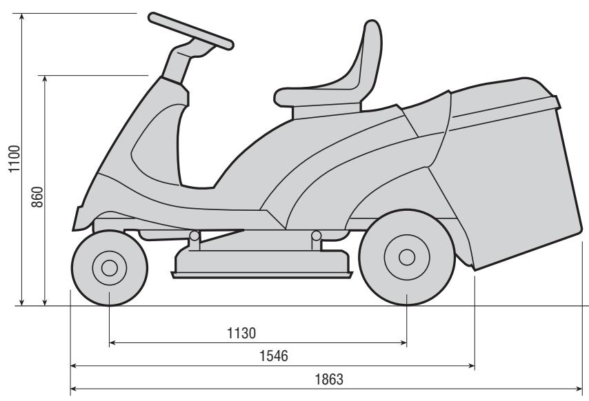
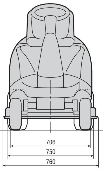
9. SPECIFICATIONS
Electrical system. 12 V
Battery 18 Ah
Front tyres 11 x 4-4
Rear tyres 15 x 6-6
Front tyre pressure 1.5 bar
Rear tyre pressure 1.0 bar
Weight 159÷168 kg
Inside turning circle (minimum
diameter of uncut area 1.4 m
Cutting height 3 ÷ 8 cm
Cutting width 71 cm
Grass-catcher capacity 170 liters
For mechanical drive models:
Forward speed (approximate) at
3000 min-1:
in 1st 1.5 km/h
in 2nd 2.7 km/h
in 3rd 4.0 km/h
in 4th 4.5 km/h
in 5th 6.8 km/h
in Reverse 2.0 km/h
For hydrostatic drive models:
Forward speed (at 3000 min ^-1 ):
in Forward drive ....... 0 ÷ 8.6 ~km / h
in Reverse . . . . . . . . . . 0 ÷ 3.2 km/h
PRESENTAZIONE
Gentile Cliente,
ACCESSO AGLI ORGANI MECCANICI
GUIDA ALLA MANUTENZIONE PROGRAMMATA
4. KIT PER “MULCHING”
in 3^a 4,0 km/h
in 4^a 4,5 km/h
in 5^a 6,8 km/h
in Retromarcia 2,0 km/h
No enroscar defaulted de"These
4. KIT PARA “MULCHING”
Service, spare parts and guarantee EC DECLARATION OF CONFORMITY
Service, spare parts and guarantee
Maintenance and repair
The maintenance and repair of modern machines, as well as all safety devices, require qualified technical training and a special workshop equipped with special tools and testing devices.
All work not described in this Instruction Manual may be done only by a properly qualified workshop or authorised service centre.
The DOLMAR service centres have all the necessary equipment and skilled and experienced personnel, who can work out cost-effective solutions and advise you in all matters.
Repair attempts by third parties or unauthorized persons will void all warranty claims.
Responsibility
On tools with engines by Briggs&Stratton, Honda, Tecumseh or Robin Subaru, the engine manufacturer or their authorised service centre is responsible for the engine only. DOLMAR is responsible for the rest of the tool (excluding the engine).
This does not apply to electrical generators and all other tools or equipment not containing engines of the above brands.
Only DOLMAR is responsible for these tools and equipment.
Spare parts
Reliable long-term operation, as well as the safety of your machine, depend among other things on the quality of the spare parts used.
Use only original DOLMAR parts.
Only original spare parts and accessories guarantee the highest quality in material, dimensions, function and safety.
Original spare parts and accessories can be obtained from your local dealer. He will also have the spare part lists to determine the required spare part numbers, and will be constantly informed about the latest improvements and spare part innovations.
Please note that the use of non-original parts renders the warranty void.
Guarantee
DOLMAR guarantees the highest quality and will therefore reimburse all costs for repair by replacement of damaged parts resulting from material or production faults occurring within the guarantee period after purchase. Please note that in some countries particular guarantee conditions may exist. If you have any questions, please contact your salesman, who is responsible for the guarantee of the product.
Please note that we cannot accept any responsibility for damage caused by:
- Disregard of the instruction manual.
- Non-performance of the required maintenance and cleaning.
- Incorrect carburetor adjustment.
Normal wear and tear. - Obvious overloading due to permanent exceeding of the upper performance limits.
- Use of force, improper use, misuse or accidents.
- Damage from overheating due to dirt on the fan housing.
- Work on the machine by unskilled persons or inappropriate repairs.
- Use of unsuitable spare parts or parts which are not original DOLMAR parts, insofar as they have caused the damage.
- Use of unsuitable or old oil.
- Damage related to conditions arising from lease or rent contracts.
Cleaning, servicing and adjustment work is not covered by the guarantee. All repairs covered by the guarantee must be performed by a DOLMAR service centre.

To find your local distributor,
please visit www.dolmar.com