HCG640VGT - Oven Freggia - Free user manual and instructions
Find the device manual for free HCG640VGT Freggia in PDF.

User questions about HCG640VGT Freggia
0 question about this device. Answer the ones you know or ask your own.
Ask a new question about this device
Download the instructions for your Oven in PDF format for free! Find your manual HCG640VGT - Freggia and take your electronic device back in hand. On this page are published all the documents necessary for the use of your device. HCG640VGT by Freggia.
USER MANUAL HCG640VGT Freggia
Thank you for purchasing Freggia built-in hob.
Please carefully read the user manual, as it contains the instructions for the safe installation, operation and maintenance of the built-in hob.
Save it for future use.
RU
We invite you to read this instruction booklet carefully, before installing and using the equipment. It is very important that you keep this booklet together with the equipment for any future consultation.
If this equipment should be sold or transferred to another person, make sure that the new user receives the booklet, so that he can learn how to operate the appliance and read the corresponding notice.
This is a class 3 appliance

Declaration of conformity:
It declared that our products comply with current European directives, orders and regulations, and fulfil the conditions set out in the reference standards.
- The installation must be carried out by experienced and qualified personnel, in conformity with the regulations in force.
- This appliance is not intended for use by person (including children) with reduced physical, sensory or mental capabilities, or lack of experience and knowledge, unless they have been given supervision or instruction concerning use of the appliance by a person responsible for their safety.
• Children should be supervised to ensure that they do not play with the appliance. - While the appliance is running, watch the children and make sure they neither stay near the equipment, nor touch the surfaces that have not cooled down completely.
- Before powering the equipment, check that it is properly adjusted for the type of gas at disposal (see the "installation" paragraph).
• Before carrying out the maintenance or cleaning the equipment, cut power supply off and make it cool down.
• Make sure that air circulates around the gas equipment. Insufficient ventilation produces a lack of oxygen. - In case of an intense or prolonged use of the equipment, it may be necessary to improve aeration, for example by opening a window or increasing the mechanical suction power, if it exists.
- The products of combustion must be discharged outside through a suction hood or an electric fan (see the "installation" paragraph).
- For any possible operation or modification, apply to an authorized Technical Assistance Centre and demand original spare parts.
The manufacturer refuses all responsibility for possible damages to things or people, resulting from a wrong installation or from an improper, incorrect or unreasonable use of this equipment.
- The appliance and its accessible parts become hot during use. Care should be taken to avoid touching heating elements. Children less than 8 years of age shall be kept away unless continuously supervised.
- This appliance can be used by children aged from 8 years and above and persons with reduced physical, sensory or mental capabilities or lack of experience and knowledge if they have been given supervision or instruction concerning use of the appliance in a safe way and understand the hazards involved. Children shall not play with the appliance. Cleaning and user maintenance shall not be made by children without supervision.
! Unattended cooking on a hob with fat or oil can be dangerous and may result in fi re. NEVER try to extinguish a fi re with water, but switch off the appliance and then cover flame e.g. with a lid or a fi re blanket.
! Danger of fi re: do not store items on the cooking surfaces.
! Don't use a steam cleaner for the cleaning the hob.
- The appliance is not intended to be operated by means of an external timer or separate remotecontrol system.
- Do not use the hob during cleaning.
- These instructions apply only if the symbol of the country appears on the appliance. If the symbol not appear on the device you need to refer to the technical instructions required that the manufacturer will provide for the amendment of the appliance in terms of use of the destination country.
- Carefully read the instructions before installing and using the appliance. The manufacturer is not responsible if the installation and improper use of the device causing injury or damage. Keep the instructions handy as a reference for the future.
GENERAL NOTICE
- Never leave the appliance unattended during food preparation because oil and grease could cause a fire.
- When the unit is connected directly to the power supply, you need a switch insulating omnipolar. It is necessary that the appliance can be completely disconnected from the network in accordance with the conditions of the category III on the overvoltage. The earth cable is not included.
- If the power cable is damaged, it must be replaced by the manufacturer, by an authorized technician or by a qualified person to avoid danger.
- When connecting the power cable, make sure it is not in direct contact (eg. through the use of insulation sleeves) with parts that can reach temperatures of over 50 °C.
! WARNING !!!!!
- DO NOT USE diff users, toasters, griddles in cast iron or stainless steel grills for meat on gas burners.
- MUST BE used only pots as described in the section "Use of the burner";
! WARNING !!!!!
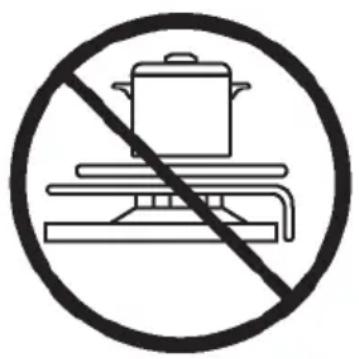
- DO NOT PLACE anything, e.g. flame tamer, asbestos mat, between pan and pan support as serious damage to the appliance may result.
- DO NOT REMOVE the pan support and enclose the burner with a wok stand as this will concentrate and deflect the heat onto the hotplate;
text_image
Prohibition sign showing a cooking pot above a table with a diagonal line, indicating no cooking activity.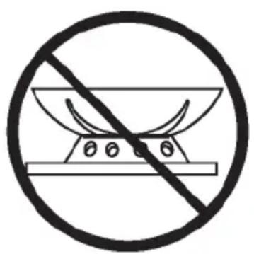
natural_image
Prohibition sign with crossed-out bowl and plate, no text or symbols present- DO NOT USE large pots or heavy weights which can bend the pan support or deflect the flame onto the hotplate.
- LOCATE pan centrally over the burner so that it is stable and does not overhang the appliance.

natural_image
Prohibition sign of a cooking pot crossed out by a diagonal line, enclosed in a circle (no text or symbols)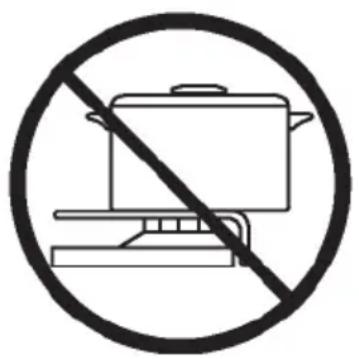
text_image
Prohibition sign showing a cooking pot crossed out by a horizontal line, indicating no cooking activity.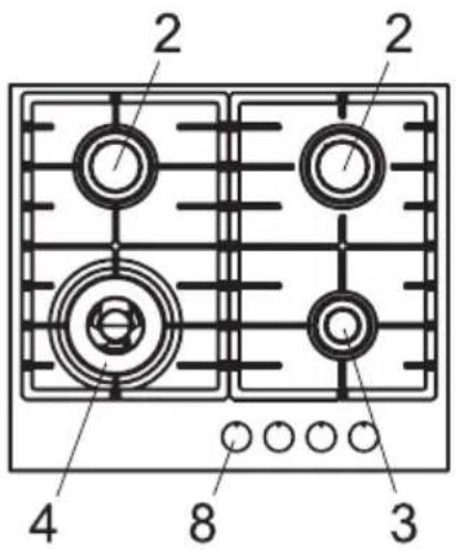
text_image
2 2 4 8 32 Semi-rapid burner 1750 W
3 Auxiliary burner 1000 W
4 Ultra-rapid burner 3500W
8 Control knobs burner
INSTRUCTIONS FOR THE USER
IT IS NECESSARY THAT ALL THE OPERATIONS REGARDING THE INSTALLATION, ADJUSTMENT AND ADAPTATION TO THE TYPE OF GAS AVAILABLE ARE CARRIED OUT BY QUALIFIED PERSONNEL, IN CONFORMITY WITH THE REGULATIONS IN FORCE.
THE SPECIFIC INSTRUCTIONS ARE DESCRIBED IN THE BOOKLET SECTION INTENDED FOR THE INSTALLER
USING THE BURNERS
The symbols silk-screen printed on the side of the knob indicate the correspondence between the knob and the burner.
• MANUAL IGNITION
Press the knob and turn it anticlockwise until it reaches the symbol on the control panel (maximum flame position) and place a lighted match or lighter near the burner.
• ELECTRICAL IGNITION
Press the knob and turn it anticlockwise until it reaches the symbol on the control panel (maximum flame position) and press the button on the control panel.
On those models fitted with a safety device, the knob must be pressed in for about 6 seconds once the burner has ignited.
• USING THE BURNERS
In order to obtain the maximum yield without waste of gas, it is important that the diameter of the pot is suitable for the burner potential (see the following table), so as to avoid that the flame goes out of the pot bottom (fig.1).
Use the maximum capacity to quickly make the liquids reach the boiling temperature, and the reduced capacity to heat food or maintain boiling. All of the operating positions must be chosen between the maximum and the minimum ones, never between the minimum position and the closing point.
The gas supply can be interrupted by turning the knob clockwise up to the closing position.
| Burners power (W) ∅ of pots | |
| Auxiliary 1000 10 - 14 cm | |
| Semi-rapid 1750 16 - 18 cm | |
| Rapid 3000 20 - 22 cm | |
| Ultra-rapid 3500 24 - 26 cm | |
INSTRUCTIONS FOR THE USER
NOTICE
- When the equipment is not working, always check that the knobs are in the closing position.
- If the flame should blow out accidentally, the safety valve will automatically stop the gas supply, after a few seconds. To restore operation, set the knob to the lighting point (large flame, fi g.1).
• While cooking with fat or oil, pay the utmost attention as these substances can catch fire when overheated. - Do not use sprays near the appliance in operation.
- Do not place unstable or deformed pots on the burner, so as to prevent them from overturning or overflowing.
- Make sure that pot handles are placed properly.
- When the burner is started up, check that the flame is regular and, before taking pots away, always lower the flame or put it out.
CLEANING
Before any operation, disconnect the appliance from the electric grid. Don't use a steam cleaner for the cleaning the hob. It is advisable to clean the appliance when it is cold.
• GLASS PLATFORM AND ENAMELLED PARTS
The glass platform and all of the enamelled parts must be washed with a sponge and soapy water or with a light detergent.
Do not use abrasive or corrosive products. Do not leave substances, such as lemon or tomato juice, salt water, vinegar, coffee and milk on the enamelled surfaces for a long time.
• STAINLESS STEEL PARTS
Stainless steel can be stained if it remains in contact with highly calcareous water or aggressive detergents for an extended period of time. The stainless steel parts should also be cleaned with soapy water and then dried with a soft cloth.
• BURNERS AND RACKS
These parts can be removed to make cleaning easier. The burners must be washed with a sponge and soapy water or with a light detergent, wiped well and placed in their housing perfectly. Make sure that the flame-dividing ducts are not clogged. Check that the feeler of the safety valve and the start-up electrode are always perfectly cleaned, so as to ensure an optimum operation.
- GAS TAPS
The possible lubrication of the taps must be carried out by specialized personnel, exclusively.
In case of hardening or malfunctions in the gas taps, apply to the Customer Service.
IMPORTANT NOTICE: THE OPERATIONS IND
THE OPERATIONS INDICATED BELOW MUST BE FOLLOWED BY QUALIFIED PERSONNEL EXCLUSIVELY, IN CONFORMITY WITH THE REGULATIONS IN FORCE.
THE MANUFACTURING FIRM REFUSES ALLRESPONSIBILITY FOR DAMAGES TO PEOPLE, ANIMALS OR THINGS, RESULTING FROM THE FAILURE TO COMPLY WITH SUCH PROVISIONS.
INSTALLATION
• INSTALLATION ROOM
This appliance is not provided with a device for exhausting the products of combustion.
Regarding room ventilation rules where appliance is installed make reference to the legislation, in conformity with the local regulations.
• FOR THE U.K. ONLY
The room containing this hotplate should have an air supply in accordance with BS 5440: Part 2:1989.
- All rooms require an openable window, or equivalent and some rooms will require a permanent vent a well.
- For room volumes up to 5m ^3 an air vent of 100cm ^2 is required.
- For room volumes between 5m ^3 and 10m ^3 an air vent of 50cm ^2 is required.
- If the room is greater than 5m ^3 and has a door that opens directly to the outside, then no air vent is required.
If there are other fuel burning appliances in the same room BS 5440: Part 2:1989 should be consulted to determine the air vent requirements
• INSTALLING THE TOP
The appliance is designed to be embedded into heat-resistant pieces of furniture.
The walls of the pieces of furniture must resist a temperature at least a 65^ C temperature.
The gas hobs are equipped with type Y degree protection against overheating. Therefore, the appliance can be installed next to cabinets, provided the height of the cabinet doses not exceed that of the hob.
The equipment must not be installed near inflammable materials, such as curtains, cloths, etc.
Make a hole in the top of the piece of furniture, with the dimensions (see fig.2), at a distance of at least 50 mm from the appliance border to the adjacent walls.
Any possible wall unit over the cook-top must be placed at a distance of at least 760 mm from the top.
It is advisable to isolate the appliance from the piece of furniture below with a separator, leaving a depression space of at least 10 mm (fi g. 3).
- FASTENING THE TOP
Every cook-top is equipped with a special washer having.
This must be placed under the edge of the box unit, as close as possible to the edge itself (fig.4). Introduce and place the cook-top in the hole made in the piece of furniture, then block it with the screws of the fastening hooks C (fig. 5).
• GAS CONNECTION
Make sure that the appliance is adjusted for the gas type available (see the label under the appliance). Follow the instructions indicated in the chapter "gas transformations and adjustments" for the possible adaptation to different gases. The appliance must be connected to the gas system by means of stiff metal pipes or fl exible steel pipes having continuous walls, in compliance with the regulations in force.
Gas enters the appliance through a cylindrical threaded male gas union (1/2").
The connection must not stress the gas ramp.
Once the installation is over, check the connection seal with a soapy solution.
INSTRUCTIONS FOR THE INSTALLER
• ELECTRIC CONNECTION
The connection to the electric grid must be carried out by qualified personnel and in conformity with the regulations in force.
The voltage of the electric system must correspond to the value indicated in the label under the appliance. Make sure that the electric system is provided with an effective ground connection in compliance with the regulations and provisions of the law. Grounding is compulsory. If the appliance is not equipped with a plug, apply a standardized plug to the power supply cable.
To connect directly to the electric net, it is necessary to be provided with a device assuring disconnection from the complete electric net. This device must be at a suitable opening distance from the contacts in order to allow the entire disconnection in case of overvoltage category III, in accordance with installation rules.
GAS TRANSFORMATIONS AND ADJUSTMENTS
• REPLACING THE NOZZLES
If the equipment is adjusted for a type of gas that is different from the one available, it is necessary to replace the burner nozzles.
The choice of the nozzles to replace must be made according to the table of the "technical characteristics".
Act as follows:
- Remove the racks and burners.
• By means of a straight spanner L, unscrew the nozzle U (fig.6 / 6A) and substitute it with the corresponding one. - Tighten the nozzle strongly.
• ADJUSTING THE BURNERS
The lowest flame point must always be properly adjusted and the flame must remain on even if there is an abrupt shift from the maximum to the minimum position.
If this is not so, it is necessary to adjust the lowest flame point as follows:
- start the burner up;
- turn the tap up to the minimum position (small fl ame);
- remove the knob from the tap rod;
- introduce a flat-tip screwdriver C in the hole F or near the tap rod (fig.7) and turn the by-pass screw up to a proper adjustment of the lowest fl ame point.
As regards G30 gas burners, the by-pass screw must be tightened completely.
MAINTENANCE
• REPLACING THE POWER SUPPLY CABLE
If the power supply cable should be replaced, it is necessary to use a cable with a section of 3 × 0.75 mm^2 , type H05VV-F or H05RR-F, complying with the regulations in force.
The connection to the terminal board must be effected as shown in fig. 8:
brown cable L (fase)
blue cable N (neutro)
green-yellow cable (terra)
| BURNERS | GAS | NORMAL PRESSURE mbar | NOMINAL RATE | INJECTOR DIAMETER 1/100 mm | TAPE BY PASS ∅ 1/100 mm | NOMINAL HEAT INPUT (W) | |||
| N° | DENOMINATION | g/h | L/h | Max. | Min. | ||||
| 2 | SEMI-RAPID | G30 | 28-30 | 120 | - | 66 | 31 | 1750 | 600 |
| G20 | 20 | - | 157 | 101 | Reg. | 1750 | 600 | ||
| 3 | AUXILIARY | G30 | 28-30 | 73 | - | 50 | 27 | 1000 | 450 |
| G31 | 20 | - | 95 | 77 | Reg. | 1000 | 450 | ||
| G20 | |||||||||
| 4 | ULTRA- RAPID | G30 | 28-30 | 255 | - | 94 | 60 | 3500 | 2100 |
| G20 | 20 | - | 334 | 137 | Reg. | 3500 | 2100 | ||
Short title or reference to the measurement and calculation methods used to establish compliance with the above requirements.
The performance of each individual burner is calculated according to standard EN 30-2-1 + A1:2003 + A2:2005
The total efficiency of the hob is calculated according to the EU Regulation 66/2014 Par. 2.2
The efficiency is calculated only for the burners with a nominal capacity exceeding 1,16 KW (EN 30-2-1 + A1:2003 + A2:2005; Par. 4.1)
Information which is relevant to the customer to minimize the energy consumption during usage:
Energy Saving Tips: use pots having flat base, Use pots with proper size, use pots with lid, minimize the amount of liquid or fat, when liquid starts boiling reduce the setting.
This product complies with EU directive 2002/96/EC.

The crossed-out dustbin symbol reported on the appliance indicates that the appliance must be disposed of separately from other domestic refuse at the end of its useful life. It must therefore be delivered to a waste recycling centre specifically for electric and electronic equipment or returned to the retailer at the moment of purchase of a new equivalent appliance.
The user is responsible for delivering the appliance to the appropriate collection centre at the end of its useful life, Failure to do so may result in a fine, as provided for by laws governing waste disposal.
Differential collection of waste products for eventual recycling, treatment and environmentally friendly disposal helps reduce possible negative effects on the environment and health, and also enables the materials making up the product to be recycled.
For more detailed information on the available refuse collection systems, refer to the local Municipal Solid
Waste disposal centre or the shop where the product was purchased.
Producers and importers are responsible for fulfilling their obligations as regards recycling, treatment and environmentally friendly disposal by directly or indirectly participating in the collection system.
The manufacturing firm refuses all responsibility for any possible imprecision in this booklet, due to misprints or clerical errors. It reserves the right to make all the changes that it will consider necessary in its own products, without affecting the essential characteristics of functionality and safety.

natural_image
Two cooking pots with crossed-out steamers, one on a stovetop and the other on a gas stove (no text or symbols)
text_image
MOD. 60-70 560 480 2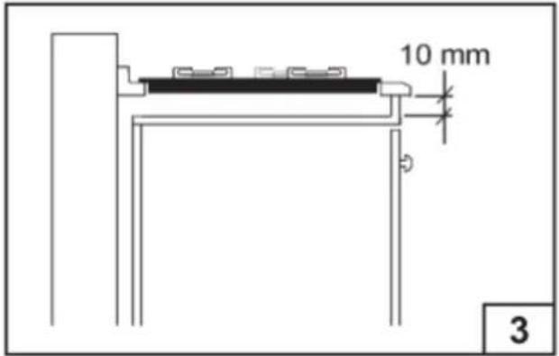
text_image
10 mm 3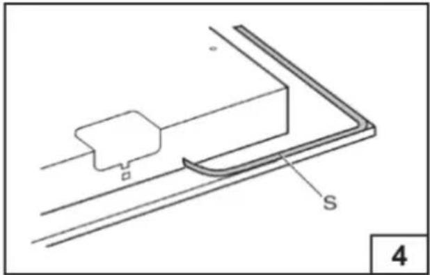
natural_image
Technical line drawing of a mechanical component with labeled parts S and a small block, no readable text or symbols present.
text_image
V G 11 5
text_image
L U 6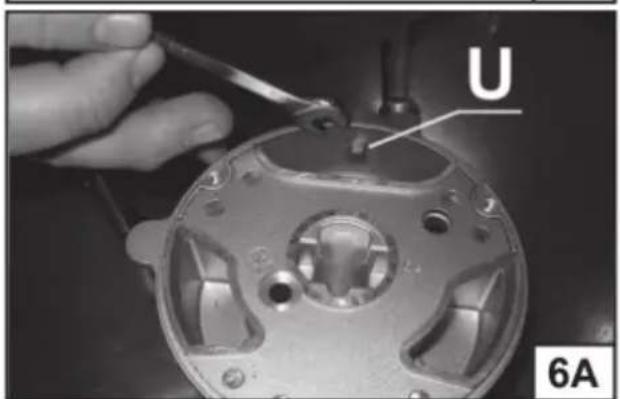
natural_image
Close-up of a hand using a tool to adjust or install a mechanical component, labeled 'U' and '6A' (no readable text beyond labels)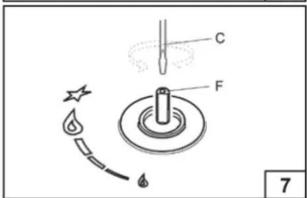
text_image
C F 7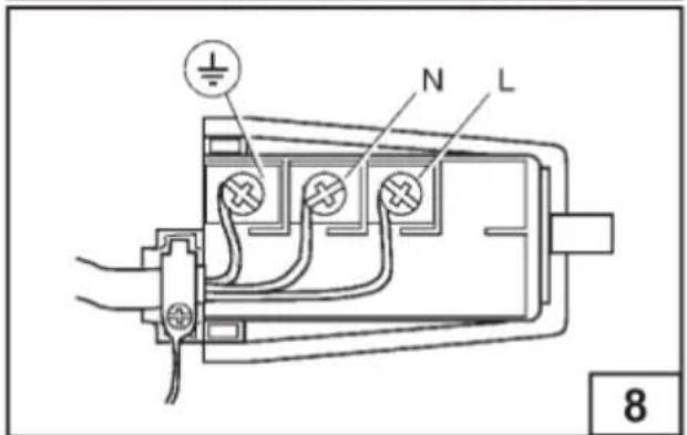
text_image
N L 8natural_image
Two cooking pots with crossed-out steamers, one heating on a stove and the other on a gas stove (no text or symbols)
text_image
MOD. 60-70 560 480 2
text_image
10 mm 3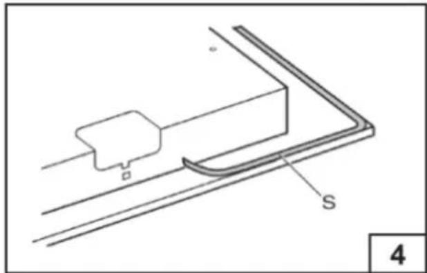
natural_image
Technical line drawing of a mechanical component with labeled parts S and a small block, no readable text or symbols present.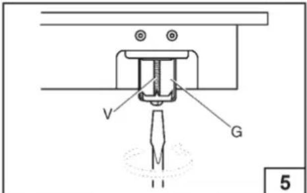
text_image
V G 5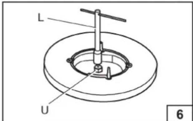
text_image
L U 6
natural_image
Close-up of a hand using a tool to adjust or repair a mechanical component, labeled 'U' and '6A' (no readable text beyond labels)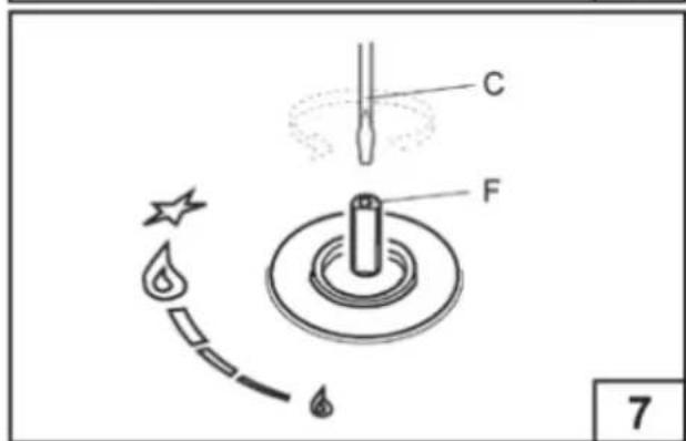
text_image
C F 7
text_image
N L 8ЗАГАЛЬНА ІНФОРМАЦІЯ

natural_image
Two cooking pots with crossed-out steamers, one on a stove and the other on a pot (no text or symbols)
text_image
MOD. 60-70 560 480 2
text_image
10 mm 3
natural_image
Technical line drawing of a mechanical component with labeled parts S and a small block, no readable text or symbols present.
text_image
V G 5
text_image
L U 6
natural_image
Close-up of a hand using a tool to adjust or repair a mechanical component, labeled 'U' and '6A' (no readable text beyond labels)
text_image
C F 7
text_image
N L 8natural_image
Two cooking pots with crossed-out steamers, one heating on a stove and the other on a gas stove (no text or symbols)
text_image
MOD. 60-70 560 480 2
text_image
10 mm 3
natural_image
Technical line drawing of a mechanical component with labeled parts S and a small component (no text or symbols beyond labels)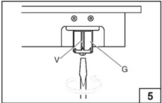
text_image
V G 11 5
text_image
L U 6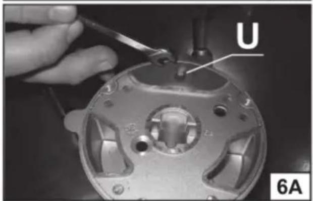
natural_image
Close-up of a hand using a tool to adjust or repair a mechanical component, labeled 'U' and '6A' (no readable text beyond labels)
text_image
C F 7
text_image
N L 8
text_image
510 580 560 55 480FOR YEARS TO COME freggia

This manual can be downloaded at www.freggia.com