
OMRB66 - Oven Freggia - Free user manual and instructions
Find the device manual for free OMRB66 Freggia in PDF.

| Product Type | Gas built-in oven |
| Brand | Freggia |
| Model | OMRB66 |
| External Dimensions (WxDxH) | 595 x 560 x 598 mm |
| Installation Cabinet Dimensions (WxDxH) | 560 x 575 x 560 mm |
| Oven Interior Volume | 53 L |
| Net Weight | 37 kg |
| Gross Weight | 40 kg |
| Power Supply | 220-240 V ~ 50/60 Hz |
| Total Maximum Power | 1275 W |
| Gas Oven Burner Power | 1.9 kW (nominal) |
| Grill Heater Power | 2000 W |
| Bottom Heater Power | 1200 W |
| Oven Burner Ignition | Automatic with safety valve; manual option in case of power failure |
| Cooling System | Automatic cooling fan motor |
| Timer Type | 60-minute mechanical timer or digital timer (model dependent) |
| Oven Door | Removable; double glass pane (inner pane removable for cleaning) |
| Safety Features | Flame failure device, safety cooling fan, child lock (supervision required) |
| Gas Types Compatible | LPG (30 mbar) and Natural Gas (G20 20 mbar); injector set provided |
| Energy Efficiency | Follow preheating and residual heat tips for energy saving |
| Cleaning | Manual cleaning with mild detergent; avoid abrasives; steam cleaning not recommended |
| Included Accessories | Oven tray, wire grill, side rail frames, injector set (if applicable) |
Frequently Asked Questions - OMRB66 Freggia
User questions about OMRB66 Freggia
0 question about this device. Answer the ones you know or ask your own.
Ask a new question about this device
Download the instructions for your Oven in PDF format for free! Find your manual OMRB66 - Freggia and take your electronic device back in hand. On this page are published all the documents necessary for the use of your device. OMRB66 by Freggia.
USER MANUAL OMRB66 Freggia
Thank you for purchasing Freggia gas build-in oven.
Please carefully read the user manual, as it contains the instructions for the safe installation, operation and maintenance of the oven.
Save it for future use.
RU
ATTENTION! Important safety information.
ВНИМАНИЕ!
Edditional recommendations regarding usage.
Care and maintenance.
COBET:
IMPORTANT SAFETY PRECAUTIONS AND RECOMMENDATIONS....3
CONTROL PANEL....5
HOW TO USE THE OVEN....6
MINUTE COUNTER....7
MAINTENANCE....8
RECOMMENDATIONS FOR THE INSTALLER......11
BEFORE FIRST USE
- Read the instructions carefully before setting up and using the appliance.
- Make sure the appliance is not damaged, after removing it from the packaging. In case of doubt, do not use the appliance and consult your supplier or a competent engineer.
- Remove all packaging materials. Do not store the packaging materials in places that children can reach, as they can cause serious injuries (plastic bags, polystyrene, tapes, etc.). Packaging materials are recyclable.
- The appliance should be installed in accordance with the regulations in force and following the instructions of the manufacturer, by a competent engineer and gas/power connections should also made by a competent engineer.
- Do not attempt to change the technical characteristics of the appliance as its use can be dangerous.
IMPORTANT PRECAUTIONS AND ADVICES REGARDING USE OF ELECTRICAL APPLIANCES
Using any electrical appliance requires compliance with a set of basic rules.
Especially:
- Never touch the appliance with wet hands or feet;
- Do not operate the appliance with bare feet;
- Do not allow children or handicapped people to operate the appliance without supervision.
Manufacturer cannot be held responsible for any damage caused by inappropriate, wrong or unreasonable use of the appliance.
USING THE OVEN FOR THE FIRST TIME
We recommend you do the following:
- Install the inner part of the oven as described under «Cleaning and Maintenance».
- Operate the oven empty for maximum temperature for two hours to remove the oil stains and smell from the parts.
- Let the oven cool down, turn off the power, and then clean the interior of the oven with a cloth dipped in neutral detergent, and wipe dry well.
IMPORTANT SAFETY PRECAUTIONS AND RECOMMENDATIONS
- Do not perform any cleaning or maintenance operation without unplugging the appliance.
- Some parts might get very hot during or after using the oven. Do not touch the hot parts.
• After use, make sure all controls are in closed position. - Home appliance is not for children's play.
- Keep children away when using the oven.
IMPORTANT SAFETY PRECAUTIONS
AND RECOMMENDATIONS
- For children and people who have a handicap that prevent them to use the appliance, a responsible person must be present to supervise them about the oven's use. The person who supervises them has to make sure that they can use the oven in a way not to damage themselves or the environment.
! WARNING
- When installed correctly, your product meets all the safety conditions foreseen for this product category. But special care should be given to the rear and bottom sides of the appliance, since it can have sharp or hard corners that can cause injuries and these areas should not be touched.
Risk of Fire! Do not store fl am- mable materials in the oven.
• Always use oven mittens when removing racks or trays from the oven while hot. -
Clean the oven regularly and do not allow oil to gather in oven floor or trays. Clean the spills right away.
-
Do not cover the oven walls with aluminum. Do not place cake molds and grill on the oven surface.
- To allow steam and hot air out before taking food out, always stay away from the oven when opening the oven door.
- Do not hang towel, drying cloth or other things inside the oven or on the oven handle. It might cause fire.
- Make sure that the power cords of other nearby appliances cannot get stuck in oven's door.
• We recommend that an unwanted appliance be rendered in-operable and all parts that can cause danger to be made not dangerous.
- Important: This appliance is designed for home use only. It is NOT fit for use in semi-commercial, commercial or common area uses.
! Cooking Safely: Keep the foods inside the oven for short durations before and after cooking. This is to prevent contamination by organisms that can cause poisoning. Take special care in hot weather.
1 2 3
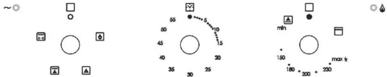
INTRODUCTION TO CONTROLS
- Function selection button
- Mechanical timer control knob
- Upper electric and lower gas burner control knob

Note:
• Electrical ignition is integrated to thermostat control knob.
- Appliance is equipped with a safety valve system. Gas flow will be cut off if flame is extinguished by accident.
CAUTION: When the burner goes off by accident, turn off the gas from the control knob and wait at least for one (1) minute before trying to light it again.
CAUTION: Gas appliances cause heat and humidity in their environment. Ensure that the cooking area is ventilated well, by opening the natural ventilation grids or mounting an aspirator to the exit channel.
CAUTION: Additional ventilation might be required by opening a window or increasing the suction power of the aspirator (if any) when the appliance is used for excessive durations.
! ATTENTION: standard frontal symbology, The product can have 3 or 4 functions. (Rotisserie required)
TECHNICAL SPECIFICATIONS
Oven is delivered completely clean.
Again, it is recommended that the oven is set to maximum temperature in first use to remove the possible oil stains from the oven burner.
The same must be applied with the gas grill as well.
This oven has the following equipment:
• One gas oven burner (1.9 kW) mounted on the floor which provides automatic ignition and safety device
COOLING FAN MOTOR
This appliance is equipped with a safety cooling fan motor that enables the maintain lower temperatures for most efficient operation of the controls and cooling the internal parts. Cooling fan motor automatically starts running when oven or grill burner is ignited.
It can keep running (for a few minutes) after the oven or grill is turned off. This duration is dependent on the previous cooking temperature and duration.
CAUTION: Oven might get very hot during operation and very hot steam might come out of the area under the control panel. Keep children away.
! Door is hot, so use the handle.
Appliance gets hot while running.
Avoid touching the heating elements inside the oven.
IMPORTANT INFORMATION:
Do not use the appliance if there is an electrical malfunction or if the cooling fan motor is damaged.
The appliance may overheat and be damaged due to cooling fan motor not operating.
In case the cooling fan motor is damaged during gas oven or gas grill operation, oven or grill burner automatically shuts down after approximately 20 minutes. In that case, do not use the appliance and call Post-Sale Service.
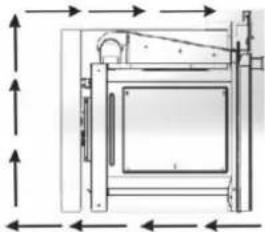
If the cooling fan motor is running correctly, an air flow is formed above the appliance (Figure 2).
natural_image
Technical line drawing of a mechanical device with dimension arrows (no text or symbols)Fig. 2
OVEN BURNER
The gas flow of the burner is regulated with a thermostat that allows the oven temperature to e kept stable.
Heat is controlled by a thermostat probe inside the oven.
The probe must always be kept clean and inside its case. A wrong location or crustation might cause changes in heat control.
Thermostat is also equipped with a safety valve that automatically shuts off the gas when the flame goes out.
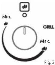
THERMOSTAT
The indicator on the control panel (Figure 3) shows the increasing oven temperature.
To regulate the heat, bring the knob onto the selected number. The symbol closest to the maximum position indicates that electrical ignition is built in the knob (it is activated by the knob itself).
IGNITING THE OVEN BURNER
IMPORTANT:
The oven door will be open during this operation.
To ignite the oven burner:
- Completely open the oven door.
Do not continue igniting the oven unless you do this.
- Press the thermostat knob to start electrical ignition and while keeping the knob pressed, turn it counter-clockwise (Figure 4) until it reaches the Maximum position (Figure 3).
Never keep this operation up longer than 15 seconds. If the burner is still not ignited, wait for around one (1) minute and repeat the ignition.
To operate the oven manually in case of an electrical malfunction, bring a fl ame close to the point «A» on the floor (Figure 5) and then press and turn the thermostat knob (Figure 4).
-
Wait for about 10 seconds after igniting the burner to release the knob (duration for thermal connection to start).
-
Make sure the burner is ignited. If not, turn the knob clockwise again to the «O» (Closed) position and repeat the operation from step one.
-
Slowly close the oven door and bring the thermostat knob to the desired setting. If the flame goes out for any reason, the safety valve will automatically cut off the gas supply to the burner.

natural_image
Diagram of a rotary dial with directional arrows indicating rotation (no text or symbols)Fig. 4

natural_image
Hand placing a button into a computer drive casing (no text or symbols visible)Fig. 5
To reignite the burner, first bring the control knob to the OFF («O») position, wait for at least one (1) minute and repeat the ignition procedure.
For correct use of the gas oven, see «COOKINGWITH GAS OVEN» chapter.
! Some parts might be very hot during and after using the oven. Keep children away.
CAUTION: Never turn the thermostat before approaching the «A» hole on the floor in case of a manual ignition.
TRADITIONAL GRILL
Warning:
Grill burner is used only when the door is open.
Leave it to heat up for approximately 5 minutes when the door is half-open. Place the food on the grill, while the rack is as close to the grill as possible. Place the tray on the suitable rack to collect the juice dripping from the food during grilling.
! Grill should not be operated for longer than 30 minutes. Caution: Oven door gets very hot while running. Keep children away.
HOW TO USE THE OVEN MINUTE COUNTER
COOKING GUIDE
Your gas oven has a burner located under the burner cap. If you are accustomed to cook with gas from before, you might have to change your cooking methods slightly. The oven floor is hot and it is ideal for baking the bottom of fl at cake molds and pizzas.
Other foods must be cooked closer to the upper part of the oven. When making cake, pita bread etc. over more than one racks, you can get the best results by switching the racks in the middle of cooking time.
- SAFETY
NEVER allow oil to gather on the oven floor.
As in all ovens, clean the oil from walls and oven floor regularly to prevent oil from flaming.
The oven is equipped with a safety cooling fan motor that enables the maintain lower surface temperatures for most efficient operation of the controls and cooling the internal parts.

Oven door might get hot - keep children away.
Never place something on the oven floor.
Do not cover the walls of the oven with aluminum.
Do not place racks or dripping tray on the oven floor.
| Heat Guide | ||
| SIGN OVEN | HEAT FOOD TO BE COOKED | |
| 1⁄2th Region Very cold oven | Meringue cakes, foods cooked in low temperature | |
| 1 Region Cold oven | Rice pudding, cakes with lots of fruit, i.e. Christmas | |
| 2 Region Cold or slow oven | Stew, casserole, foods cooked in low fire, rich fruit cakes, i.e. Dundee | |
| 3rd Region Cold or slow oven | Biscuits, fl at cakes, i.e. Madeira, frying in low temperature | |
| 4th Region Warm oven | Flat cakes, Victorian sandwich, mince pie, chicken | |
| 5th Region Medium-warmoven Small cakes, pies, fi sh | ||
| 6th Region Somewhat hot oven | Flat cakes, fruit cakes, frying in high temperature | |
| 7th Region Hot oven | Bread and loaves of bread, etc. pita bread, fl at puff pastry, frying in high temperature | |
| 8th Region Medi um-hot oven Sausages, pastry, puff pastry, pizza, meat | ||
| 9th Region Very hot oven Food ready to be fried | ||


60-MINUTE COUNTER
Minute counter is a sound-warning device that can be set to 60 minutes.
Turn the knob (Figure 9) clockwise until it come to the 60 minutes position and then bring it to the desired time by turning it counter-clockwise.

IMPORTANT WARNING:
This is only a mechanical timer.
Do not forget to turn off the oven/grill manually.
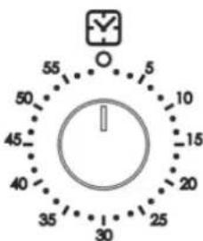
Fig. 9
DIGITAL TIMER

Minute Minder Icon
Dot Icon
1: Minute Minder Button
2: Minus Button

3: Plus Button
2 and 3: Watch Adjustment
• SETTING THE TIME OF DAY (24 H CLOCK)
After you connect or reconnect to a power source after you have power outage, «0.00» fl ashes.
- Press button 1 for approx. 2 sec., the dot icon starts flashing. Set the current time using buttons 2 and 3. About 7 seconds after the set time has been selected, the new data is stored. The time correction can be done later in this way:
- Press button 2 and 3 simultaneously for approx. 2 sec., the dots icon starts flashing and you can set the current time.
Wait about 7 seconds and the new data will be stored.
• SETTING THE MINUTE MINDER
The time that you can set varies from 1 minute to 23 hours 59 minutes.
- Press button 1 until the alarm icon starts flashing and the display shows «0.00».
- Enter the desired time using buttons 3 and 2. Wait approx. 7 seconds until the alarm icon is fixed on the display and the setting is stored. After the set time has elapsed, a beep is emitted and the alarm icon starts flashing again.
• Press keys 1, 2 or 3 to turn off the audible signal;
Then press button 1 for approx. 2 seconds and the alarm icon disappears and the display shows the current time.
• CHANGE THE TIMER BEEPS
The tone of the timer beeps may be changed as follows:
• Press buttons 2 and 3 simultaneously,
- Press button 1 to see actual tone "ton1" to see on the display.
• Press button 2 to select the tone you wish from 1 to 3.
Wait approximately 7 seconds and the tone will be set, then reappear on the screen the current time.
• CANCEL SETTINGS
Cancel minute minder settings:
• Press button 1 to select minute minder settings,
• Press buttons 2 and 3 to increase or decrease the time
MAINTENANCE
We recommend that you clean the appliance when it is cold, especially the enamel parts. Avoid using alkaline or acidic materials (lemon juice, vinegar, etc.) on the surfaces. Do not use chlorine or acid-based cleaning agents.

WARNING
When installed correctly, your product meets all the safety conditions foreseen for this product category. But special care should be given to the rear and bottom sides of the appliance, since it can have sharp or hard corners that can cause injuries and these areas should not be touched.
• INSIDE THE OVEN
The oven must always be cleaned when cold after use. Clean the gap with a mild detergent solution and warm water.
Appropriate chemicals can be used after consulting the recommendations of the manufacturer and trying it on a small part of the gap. Abrasive cleaning agents or abrasive clothes must not be used on the surfaces of the gap.

NOTE: The manufacturer of this appliance does not take responsibility for damages caused by chemicals or abrasive cleaning.
• ENAMEL PARTS
All enamel parts are cleaned only with sponge and soap water, or otherwise non-abrasive products.
Drying with a microfiber or soft cloth is preferred.
• STAINLESS STEEL, ALUMINUM, PAINTED PARTS AND SILKSCREEN SURFACES
Clean using an appropriate product. Always dry thoroughly.

IMPORTANT: These parts must be cleaned very carefully to prevent scratches and wear. Use a soft cloth and acid-free soap.
• GLASS CONTROL PANEL (Only in some models)
Clean using an appropriate product. Always dry thoroughly.
Do not use hard abrasive cleaning agents or sharp-edged metal scratchers to clean the control panel as they may scratch the surface and cause the glass to break.
| IMPORTANT:Cut off the appliance's power before you start cleaning. | CAUTION:Wait for the oven to cool down and take care not to touch the hot heating elements inside the oven gap. | WARNING:Do not use abrasive materials or acidic detergents as they will scratch the surface without repair. |
| IMPORTANT:Do not use steam cleaning appliances as the humidity can get into the oven and make the appliance unreliable. | CAUTION:Do not store foreign materials inside the oven. | WARNING:Do not use hard abrasive materials or sharp-edged metal scratchers as they will scratch the surface beyond repair and may cause the glass to break. |
REPLACING THE OVEN LAMP
WARNING: To prevent electric shock, make sure the appliance is turned off before replacing the lamp.
- Leave the oven gap and heating elements to cool down.
• Cut off the power connection. - Remove the protective cover «A» (Figure 10).
- Remove the bulb «B» and replace with a bulb suitable for high temperatures (300°C) that is 230 V or 220-240 V, E14 specifications (Check the Watt power on the bulb).
- Replace the protective cover «A».
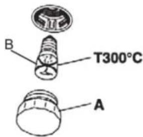
Fig. 10
INSTALLATION AND REMOVAL OF SIDE RAIL FRAMES
- Place the side rail frames into the holes on the side walls inside the oven (Figure 11).
- Place the racks as shown.
- Follow the reverse order to remove.

natural_image
Two-panel photo showing hands holding a tool inside a storage unit, no visible text or symbolsFig. 11
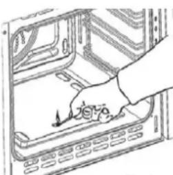
REMOVING THE OVEN DOOR
Be careful, oven door is heavy. When in doubt, do not try to remove the door.
Oven door can be removed as follows:
- Open the door to the end (Figure 13)
• Completely open the A arm on the left and right hinges (Figure 14). - Hold the door as shown in Figure 12.
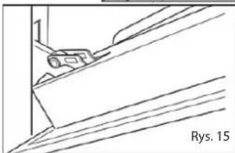
- Close the door slowly (Figure 15) until the left and right hinge arms A lock on the B part of the door (Figure 14).
- Follow Ok C and remove the hinge hooks from their places (Figure 16).
- Place the door on a soft surface.

natural_image
Line drawing of a person installing or adjusting a door panel (no text or symbols present)
natural_image
Technical line drawing of a mechanical bracket or clamp assembly (no text or symbols)

natural_image
Technical line drawing of a mechanical component with diagonal lines and a small inset detail (no text or symbols)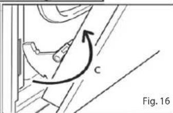
natural_image
Technical diagram showing a mechanical component with an arrow indicating rotational motion (no text or symbols present)PLACING THE OVEN DOOR BACK
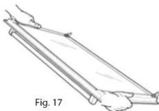
- Hold the door fast (Figure 17).
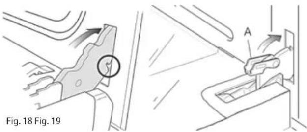
- Place the hinge latches in the gaps and make sure that the gap is fitted into place as in figure 18.
- Open the door to the end.
- As seen in Figure 19, completely close the «A» arms on the left and right side.
- Close the door and make sure it fitted into place.
natural_image
Line drawing of a person using a lever on a wooden plank, labeled Fig. 17 (no text or symbols on the diagram itself)- REMOVING AND REINSTALLING THE INNER DOOR PANE FOR CLEANING
If you want to clean the inner glass of the door, closely follow the precautions and instructions.
Replacing the glass pane and the door wrongfully causes the oven to be damaged and voids the warranty.

IMPORTANT!
- Oven door is heavy, take care. When in doubt, do not try to remove the door.
- Make sure the oven and all its parts are cooled down. Do not attempt to replace the parts of a hot oven.
- Exercise maximum caution when working with the glass pane. Ensure the glass edges to not crash into any surface. Glass might break.
- Do not use hard abrasive cleaning agents or sharp-edged metal scratchers to clean the control panel - as they may scratch the surface and cause the glass to break.
- Do not use the oven if you see any damage (crack or break) on the glass pane. Call Authorized Service or Customer Services.
- Make sure you replaced the glass pane correctly. Do not use the oven when glass pane is not correctly placed.
- Do not force the glass pane if you are having difficulty removing or replacing it. Call Authorized Service or Customer Service for help.

Note: The visits made for use or maintenance of the oven are not covered under warranty.
REMOVING THE INNER GLASS PANE
The oven door has two panes:
- 1 glass outer
- 1 glass inner
To clean all panes from both sides, the inner pane must be removed as specified below:
natural_image
Technical line drawing of a mechanical clamp or bracket assembly (no text or symbols)-
Open the door
-
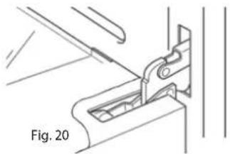
Open the door to the end (Figure 20)
• Completely open the A arm on the left and right hinges (Figure 21). -
Close the door slowly (Figure 22) until the left and right hinge arms A lock on the B part of the door (Figure 22).
-
Remove the inner pane:
• Pull the glass inner pane slowly (Figure 23).
- Clean the glass with appropriate cleaning agent. Dry throughout and place on a soft surface.
Now you can clean the inner side of the outer glass as well.

Fig. 21
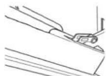
Fig. 22

Fig. 23
• REPLACING THE INNER GLASS PANE AFTER CLEANING
When replacing the inner glass pane:
- make sure you replaced the pane correctly as shown. Pane must be in the position specified below to fit in the door and to ensure oven's safe and correct operation.
- Ensure that glass edges do not crash into an object or surface.
- Do not try to force the pane into place.
If you're having difficulty replacing the pane, remove it and start over. Otherwise call Customer Service.
To install the inner glass pane:
- Make sure the door is open
- Replacing the inner glass pane:
- Ensure that four rubber seats are in place (Figure 25).


IMPORTANT: When reinstalling the glass, we recommend that you hold the four rubber seat D in place to prevent the rubber seals from breaking or sliding off.
- Make sure you hold the pane correctly. You should be able to read the texts on it when it's facing you.
-
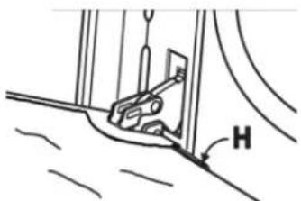
- Fit the pane into the left E and right F guide rails (Figure 25) and slide up to the holders H (Figure 26).
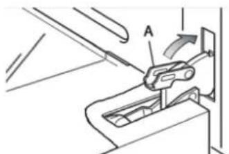
- Open the oven door completely and close the arms A on the left and right hinges, and open the door (Figure 27).
natural_image
Simple line drawing of a mechanical component with labeled angle H (no text or symbols beyond the label)Fig. 26
natural_image
Mechanical assembly diagram showing a lever mechanism with labeled component A (no text or symbols present)Fig. 27
MAINTENANCE
WHAT SHOULD / SHOULDN'T BE DONE
• Always grill with the door half-open.
- Read the user instructions carefully before using the oven for the first time.
- Before using the oven for the first time, operate the oven empty for two hours to remove the odors caused by new oven insulation.
- Clean your oven regularly.
- Clean the spills immediately.
• Always use oven mittens when removing the racks and trays from the oven.
- Do not allow children to come near the oven when in operation.
- Do not allow oil to gather on the tray or oven floor.
- Do not place food bowls or plates directly on the oven floor.
- Do not grill oily food without using the wire grill.
- Do not cover the grill with aluminum folio.
- Do not use the over tray for frying.
- Do not immerse enamel parts in water when hot. Let them cool down first.
- Do not allow vinegar, coffee, milk, salt water, lemon or tomato juice to come into contact with enamel parts (inside the oven or over the oven tray).
- To not use abrasive cleaning agents or powders that scratch the surfaces and enamel.
- Do not attempt to repair the inner equipment of your oven.
- Remove the protective fi Im before fi rst use.
- Do not perform any cleaning or maintenance without cutting off the power connection of the appliance.
• Risk of fire! Do not store flammable materials in the oven.
• FOR YOUR SAFETY
The product should be used only for the intended purpose; to cook at home.
No external covers must be removed by unauthorized people for servicing or maintenance.
• IMPORTANT NOTES
The oven will be installed by competent and authorized people in accordance with the related standards.

CAUTION:
The appliance gets very hot, especially around cooking areas. Do not leave your children unattended in the kitchen while cooking.
The installation and maintenance of the appliance shall be performed only by AUTHORIZED TECHNICIANS and in accordance with local safety standards.
- Cut off the power connection of the appliance when performing any maintenance or repair operation.
- The walls around the oven must be made from fi re-resistant material.
• DO NOT lift the oven from the door handle.

WARNING
When installed correctly, your product meets all the safety conditions foreseen for this product category. But special care should be given to the rear and bottom sides of the appliance, since it can have sharp or hard corners that can cause injuries and these areas should not be touched.
- LOCATION
The appliance can be installed to the kitchen, kitchen/living room or living room, but it cannot be installed in bathroom or a location where shower is present.
The appliance must not be installed to a living room smaller than 20 m ^3 . The appliance is designed only for domestic use, and should not be installed on commercial, semi-commercial or common areas.
The oven is designed to fit into a cabinet of 600mm width.
The oven can be installed into or under kitchen units, but it should be wellventilated.
The fl ushed oven in the diagram is ventilated from the opening left in the upper part of the kitchen cabinet.
Many other methods are available to ventilate the oven. Consult an engineer for advice.
- IMPORTANT
Ensure that air can flow freely around the case area.
Not having enough ventilation can cause the appliance to overheat or cause the units around to malfunction.
Place the oven on the rack carefully, but DO NOT lift by the door handle.
When you take the oven door down, you will see 4 screw holes, 2 on each side of the oven.
Fix the oven to the case using these screw holes.
The case should not stand free. It should be fixed to the wall and/or adjacent fixtures.

Open the door and fix the oven with four wood screws which must be screwed through the holes in the lateral jambs of the oven.

natural_image
Line drawing of an oven with ventilation grilles and control knobs (no text or symbols)ELECTRICAL CONNECTION
- The device must be connected to the main electricity grid only by authorized electricity technicians in accordance with the laws and regulations in force.
- Make sure that the power from the main grid is enough to supply the power stated in the information tag placed on the front bottom of the device.
- If the current of fuse in your house is less than 16 Ampere, have a qualified electrician connect a 16 Ampere fuse.
WARNING: The device must absolutely be grounded.
- Your oven includes a grounded plug mounted on the grid cord. This plug must be used with a grounded line. Have a licensed electrician do the grounding installation.
Before supplying electricity to the device:
- Place the oven in a way to make reaching the plug used for electricity connection or double pole switch easier.
- Do not let the electricity cable touch hot surfaces when placed and do not pin it to the oven lid.
- Contact the nearest authorized service if the electricity cable is damaged. Make sure authorized service makes the chance with a new cable with plastic insulation at the same size and that can withstand the electricity current the oven needs.
- A double pole switch with at least 3 mm between the contact points between the device and the electric wire and suitable for carrying the desired load in accordance with the laws in force must be installed if the device is to be connected directly to the electric wiring. Ground wire must not be cut be double pole switch.
- It is not advised to use adapters, multi plugs or extension cords. If absolutely necessary, adapters or extension cords in line with safety laws can be used. However, never go beyond the maximum current capacity and maximum power stated for the adapter.
- Test heating elements for 3 minutes after the connections are done.
- Electricity safety of the device is guaranteed only if connected to suitable source correctly with grounding in accordance with the rules. Our company cannot be held responsible for the damages to people, animals or properties due to the failure to ground the device properly.
WHEN THE DEVICE IS INSTALLED INITIALLY:
- Set the Temperature Control to maximum level. (250 C MAX)
- Set the Function button as Top and Bottom Grill (and + Fan if available).
- Run the oven in this setup for 30 minutes.
- Open a window for air circulation.
A smoke and smell resulting from insulation materials and heating elements can be experienced for once during this period. If this happens, wait for the smoke and smell to dissipate before placing food inside the oven.
After these are done, clean the interior of the oven with a slightly wet soapy soft cloth.
IMPORTANT: Always use the middle section of the handle when opening the lid of the oven.
WARNING: Carefully wash parts such as tray, grid etc before the first use of the oven.
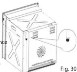
FIXING THE OVEN

natural_image
Line drawing of a kitchen sink with a tray and door, no text or symbols presentPlace the oven to the gap in the cabinet and fix with 4 screws, as shown in Figure 29.
As the purpose of the fixing with screws is only complementary, make sure the oven stands on a surface that supports its weight. To allow 4-5mm gap between the cabinet door and the oven frame, adjust the hinged of the cabinet doors next to the oven.
IMPORTANT:
To prevent the lower rail from being damaged, Fig. 29 follow the instructions below.
Lower rail is designed to ensure better ventilation and correct opening of the oven door. To make sure that the rail is not damaged due to the appliances mounted on the floor, the appliance should be supported as shown here.
After installation, the appliance door should be slowly opened to make sure no damage has occurred.
If these instructions are not adhered to, no responsibility shall be taken for lower rail damages.
VENTILATION CONDITIONS
- In rooms with a volume below 5 m ^-3 , continuous free air ventilation of 500 cm ^2 is required.
- For rooms with a volume between 5 m3 to 10 m ^-3 , continuous free air ventilation of 100 cm ^2 is required. If the room has a door opening directly outdoors, continuous ventilation is not required.
- Continuous ventilation is not required for rooms with over 10m^-3 volume.
Not: Irrelevant with the room size, all the rooms that the appliance is installed in must have an opening window or direct access to outdoors air through equivalent means.
- The conditions specified above allow the use of a gas oven and grill, but if there are other gas appliances in the same room, consult a competent engineer.
GAS CONNECTION
Warning: Appliance should be installed only by a competent and authorized installer who also has knowledge of electricity. He/she will observe the regulations and application laws that govern the installation of gas appliances.
Note: The gas connection of the appliance must be made by a fl exible tube
- Flexible hoses may be used in places where the environment temperature of the hose is not above 70^ C.
The hose should not be crushed, squeezed and come into contact with sharp or abrasive edges.
If the installation will be made using flexible connections the points below shall be observed:
Note: The fi nal connection to the gas fi xture pipes and appliance connection pipe shall be in the size that can maintain the heat output specifi ed in the appliance installation hapter.
- The fl exible connection of the appliance should not be subjected to unsuitable forces neither during normal use nor when connected or not connected.
-
The fl exible connection of the appliance must not be subjected to excessive heat due to contact with hot surfaces or direct exposure to chimney products.
-
The socket that the fl exible connection of the appliance shall be fitted into must be continuously connected to a gas fixture pipe that is strongly connected and the hose freely dangling below.
-
The fl exible connection of the appliance shall be placed as not to suffer mechanical damage, for example due to wear or squeezing with fl xing device by kitchen furniture like doors or drawers during use.
natural_image
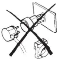
Diagram of a device with X-shaped cutouts and a magnified inset showing a small object, labeled 'Figure 30' (no text or symbols on the diagram itself)-
Plug-in connection should be accessible to be able to be cut off after the device is moved.
-
Remove the glass protection by turning as indicated in the figure on the left side. If you - Ovens with high efficiency in electricity use and heat insulation should be preferred.
- Frequently opening the oven lid causes cold air outside the oven to enter inside, thereby causing energy loss. Therefore, oven lid shouldn't be opened if not necessary.
- You shouldn't try to cook more than one meal in the oven at once. Meals that cook earlier should be taken out first, thereby use less energy without changing oven temperature.
- Residual heat after the meal cooked in the oven should be used for another meal. You will save energy this way.
- Preheating should be done for a short time (10 minutes the most).
- Frozen meals should be deiced before cooking in the oven.
• Combustible, infl ammable materials that ignite easily must be kept away from the oven. - Ovens must be installed on a location far from infl ammable environments.
- Ovens will continue cooking in current temperature by using less energy if the lid is closed a few minutes before cooking.
OVEN TECHNICAL SPECIFICATIONS
| Injector Selection Table | ||||
| BURNERS | Nominal Power [kW]LPG30mb | Reduced Power[kW] | LPG 30mb | |
| Injector diameter[1/100 mm] | Ring gap[mm] | |||
| Oven | 1,9 | - | 70 | Completely open (*) |
| BURNERS | Nominal Power [kW]G20mb | Reduced Power[kW] | Natural Gas G20mb | |
| Injector diameter[1/100 mm] | Ring gap[mm] | |||
| Oven | 1,9 | - | 97 | 2(*) |
| Bottom Heater 1200 W | |
| (*) = Reference value 15-25 W | |
| Cooling Fan 22 W | |
| Oven Lamp 25 W | |
| Turbo Fan 25 W | |
| Oven External Dimension (WxDxH) | 595x560x598 mm |
| Installation Cabin Dimension WxDxH) | 560x575x560 mm |
| Oven Interior Volume | 53 lt |
| Net Weight | 37 Kg |
| Gross Weight | 40 Kg |
| Voltage | 220-240V 50-60 Hz |
| Maximum Power | 1275 W |
| Supply voltage | 220-240 V 50/60 Hz. |
| Grill heater | 2000 W |
| Supply voltage | 220-240 V 50/60 Hz. |
ENVIRONMENTAL WARNING:
• After you installed your product, please dispose of its packaging materials according to the safety and environment conditions.
IMPORTANT: All interventions regarding appliance installation, maintenance and conversion must be made with original factory parts. Manufacturer refuses all responsibility caused by not adhering to this liability.
REPLACEMENT OPERATIONS FOR OVEN AND GRILL BURNER INJECTORS.
Some models are provided with an injector set for different gas types.
If the injector is not supplied, it can be purchased from Service Center.
Select the injectors to be changed from the «Injector Selection Chart »
The jet diameters specified in one hundredth of a millimeter are marked on the body of each injector.
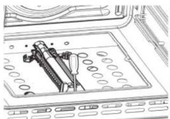
OVEN BURNER
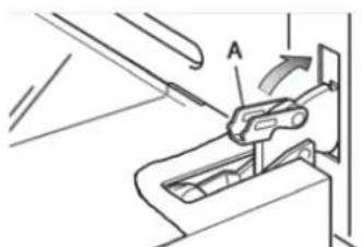
- Lift and remove the lower pane inside the oven.
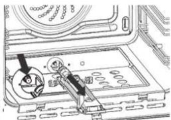
- Remove the screws and remove the burner screw «A» (Figure 31).
- Remove the burner as shown in Figure 29 and place it into the oven. Take care not to damage the safety valve probe and electrical ignition electrode.
- Remove the screws of the injector using 7 mm box strainer (shown with an arrow in Figure 32) and replace with a new injector selected according to the «Injector Selection Chart».
- Adjust the air supply to the oven burner as specified in the «Oven and Grill Burners Air Supply Adjustment» chapter; then follow the steps in reverse order to replace the burner and other parts back into their places.
IMPORTANT: Checkwhether the safety valve and the ignition electrode work correctly or not.
- Remove the screws and remove the burner screw «A» (Figure 33).
- Remove the burner as shown in Figure 34. Take care not to damage the safety valve probe and electrical ignition electrode.
- Remove the screws of the injector using 7 mm box strainer (shown with an arrow in Figure 34) and replace with a new injector selected according to the «Injector Selection Chart».
- Adjust the air supply to the grill burner as specified in the «Oven and Grill Burners Air Supple Adjustment» chapter; then follow the steps in reverse order to replace the burner and other parts back into their places.
natural_image
Technical line drawing of a mechanical assembly with no visible text or symbolsFig. 31

natural_image
Technical line drawing of a mechanical assembly with gears and a tool (no text or symbols)Fig. 32
| Primer Air Insufficient | Correct Air | Primer Air TooMuch |
| spread, yellow and flickering | light insides blue cone | short and sharp too blue inner cone, prone to separation |
Primer Air Air | Correc t Air t Air | Primer Air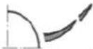 TooMuch TooMuch |
| CAUSE | ||
| Air adjustment bottle closed too much | Bottle in correct distance | Air adjustment bottle open too much |
natural_image
Pure electrical circuit lines without any symbols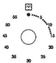
radar
| Angle (°) | Value | |-----------|-------| | 0 | 5 | | 45 | 10 | | 90 | 15 | | 135 | 20 | | 180 | 25 | | 225 | 30 | | 270 | 35 | | 315 | 40 | | 360 | 45 | | 405 | 50 | | 450 | 55 |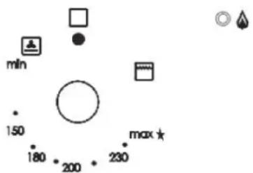
1 2 3
natural_image
Pure technical diagram of a mechanical assembly with no text, numbers, or symbolsРис. 2
natural_image
Diagram of a rotary dial with directional arrows indicating rotation (no text or symbols)Рис. 4

natural_image
Hand placing a component into a server rack (no text or symbols visible)Рис. 5
natural_image
Two-panel photo showing hands installing or adjusting a mechanical component inside a storage unit (no visible text or symbols)natural_image
Line drawing of a person installing or adjusting a door panel (no text or symbols)
natural_image
Technical line drawing of a mechanical component with no visible text or symbols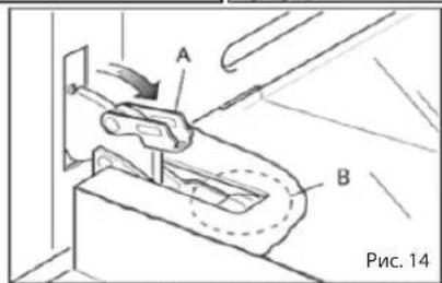

natural_image
Line drawing of a mechanical component or bracket with diagonal lines and a small object, labeled 'Рис. 15' at bottom right (no other text or symbols)
natural_image
Illustration of a hand holding a long cylindrical object with a handle, labeled 'Рис. 17' (no other text or symbols)natural_image
Technical line drawing of a mechanical clamp or bracket assembly (no text or symbols)Рис. 26 Рис. 27
natural_image
Line drawing of an oven with ventilation grilles and doorways (no text or symbols)natural_image
Diagram of mechanical components including a fan, gear, and clamp (no text or labels)natural_image
Line drawing of a kitchen sink with a tray and door, no text or symbols presentnatural_image
Line drawing of a washing machine with a fan-shaped vent and label 'Рис. 30' (no text or symbols on the diagram itself)natural_image
Technical line drawing showing mechanical assembly and component alignment (no text or symbols)Рис. 31 Рис. 32
Мал. 4
natural_image
Hand placing a component into a server rack (no text or symbols visible)Мал. 5
natural_image
Two-panel image showing hands holding a tool on a metal panel, with no visible text or symbols.natural_image
Two technical line drawings of a door frame assembly, one showing hand placement and the other showing clamping mechanism (no text or symbols)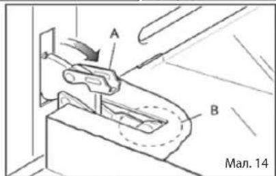

natural_image
Line drawing of a person holding a long object, labeled 'Mal. 17' (no other text or symbols)
natural_image
Technical line drawing of a mechanical clamp or bracket assembly (no text or symbols)natural_image
Technical line drawing showing three-step assembly steps: part A is a mechanical clamp, part B is a cable or connector, and a hand pressing a component on a flat panel (no text or symbols)Мал. 26 Мал. 27
natural_image
Line drawing of an oven with ventilation grilles and control knobs (no text or symbols)natural_image
Pure mechanical diagram showing intersecting rods and components without any text or symbolsПЕРШЕ ВИКОРИСТАННЯ
natural_image
Line drawing of a kitchen oven with a tray and door, no text or symbols presentnatural_image
Technical line drawing of a washing machine with fan and bulb components (no text or symbols)ЕНЕРГЕТИЧНА ЕФЕКТИВНІСТЬ ДУХОВОЇ ШАФИ
natural_image
Technical line drawing of a mechanical assembly with no visible text or symbols
natural_image
Technical diagram of a mechanical assembly with gears and housing (no text or symbols)Мал. 31 Мал. 32
natural_image
Technical line drawing of a mechanical assembly with dimension arrows (no text or symbols)PALNIK GAZOWY
natural_image
Diagram of a rotary device with rotating coil and control knob (no text or symbols)Rys. 4

natural_image
Hand placing a button into a computer oven (no text or symbols visible)Rys. 5
Rys. 10
WYJMOWANIE BOCZNYCH DRABINEK
natural_image
Two-panel photo showing hands installing or adjusting a mechanical component inside an appliance (no visible text or symbols)Rys. 11
ZDEJMOWANIE DRZWICZEK PIEKARNIKA
natural_image
Line drawing of a hand holding a rectangular object inside a window frame (no text or symbols)
natural_image
Technical line drawing of a mechanical bracket or clamp assembly (no text or symbols)
natural_image
Pure technical line drawing of a mechanical component or bracket (no text or symbols)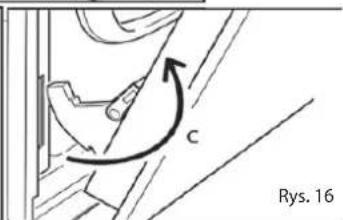
MONTAŻ DRZWI
natural_image
Line drawing of a person using a tool to lift a flatboard, labeled 'Rys. 17' (no other text or symbols)- WYJMOWANIE I PONOWNA INSTALACJA SZYBY WEWNĘTRZNEJ W DRZWIACH PIEKARNIKA
natural_image
Technical line drawing of a mechanical clamp or bracket assembly (no text or symbols)natural_image
Technical line drawing of a mechanical assembly with labeled component H (no text or symbols beyond label)Fig. 26
natural_image
Technical line drawing of a mechanical device with labeled component A (no text or symbols beyond label)Fig. 27
ZALECENIA UŻYTKOWANIA
natural_image
Line drawing of an oven with doors and ventilation slots (no text or symbols)natural_image
Pure mechanical diagram showing intersecting rods and components without any text or symbolsPRZED PIERWSZYM URUCHOMIENIEM:
natural_image
Line drawing of a kitchen sink with a tray and door, no text or symbols presentnatural_image
Diagram of a washing machine with X-bracing and fan blade, labeled Rys. 30 (no text or symbols on the device itself)ZALECENIA DLA INSTALATORA
EFEKTYWNOŚĆ ENERGETYCZNA
natural_image
Technical line drawing of a mechanical assembly with no visible text or symbolsFig. 31
natural_image
Technical line drawing of a mechanical assembly with gears and a base plate (no text or symbols)Fig. 32
This manual can be downloaded at
www.freggia.com


- RU
- BEFORE FIRST USE
- IMPORTANT PRECAUTIONS AND ADVICES REGARDING USE OF ELECTRICAL APPLIANCES
- USING THE OVEN FOR THE FIRST TIME
- IMPORTANT SAFETY PRECAUTIONS AND RECOMMENDATIONS
- IMPORTANT SAFETY PRECAUTIONS
- AND RECOMMENDATIONS
- ! WARNING
- INTRODUCTION TO CONTROLS
- TECHNICAL SPECIFICATIONS
- COOLING FAN MOTOR
- IMPORTANT INFORMATION:
- OVEN BURNER
- THERMOSTAT
- IGNITING THE OVEN BURNER
- IMPORTANT:
- TRADITIONAL GRILL
- HOW TO USE THE OVEN MINUTE COUNTER
- COOKING GUIDE
- - SAFETY
- 60-MINUTE COUNTER
- DIGITAL TIMER
- • SETTING THE TIME OF DAY (24 H CLOCK)
- • SETTING THE MINUTE MINDER
- • CHANGE THE TIMER BEEPS
- • CANCEL SETTINGS
- MAINTENANCE
- WARNING
- • INSIDE THE OVEN
- • ENAMEL PARTS
- • STAINLESS STEEL, ALUMINUM, PAINTED PARTS AND SILKSCREEN SURFACES
- • GLASS CONTROL PANEL (Only in some models)
- REPLACING THE OVEN LAMP
- INSTALLATION AND REMOVAL OF SIDE RAIL FRAMES
- REMOVING THE OVEN DOOR
- PLACING THE OVEN DOOR BACK
- - REMOVING AND REINSTALLING THE INNER DOOR PANE FOR CLEANING
- IMPORTANT!
- REMOVING THE INNER GLASS PANE
- • REPLACING THE INNER GLASS PANE AFTER CLEANING
- WHAT SHOULD / SHOULDN'T BE DONE
- • FOR YOUR SAFETY
- • IMPORTANT NOTES
- CAUTION:
- - LOCATION
- - IMPORTANT
- ELECTRICAL CONNECTION
- WARNING: The device must absolutely be grounded.
- Before supplying electricity to the device:
- WHEN THE DEVICE IS INSTALLED INITIALLY:
- IMPORTANT: Always use the middle section of the handle when opening the lid of the oven.
- WARNING: Carefully wash parts such as tray, grid etc before the first use of the oven.
- FIXING THE OVEN
- VENTILATION CONDITIONS
- Not: Irrelevant with the room size, all the rooms that the appliance is installed in must have an opening window or direct access to outdoors air through equivalent means.
- GAS CONNECTION
- Note: The gas connection of the appliance must be made by a fl exible tube
- Note: The fi nal connection to the gas fi xture pipes and appliance connection pipe shall be in the size that can maintain the heat output specifi ed in the appliance installation hapter.
- ENVIRONMENTAL WARNING:
- ПЕРШЕ ВИКОРИСТАННЯ
- ЕНЕРГЕТИЧНА ЕФЕКТИВНІСТЬ ДУХОВОЇ ШАФИ
- PALNIK GAZOWY
- WYJMOWANIE BOCZNYCH DRABINEK
- ZDEJMOWANIE DRZWICZEK PIEKARNIKA
- MONTAŻ DRZWI
- - WYJMOWANIE I PONOWNA INSTALACJA SZYBY WEWNĘTRZNEJ W DRZWIACH PIEKARNIKA
- ZALECENIA UŻYTKOWANIA
- PRZED PIERWSZYM URUCHOMIENIEM:
- ZALECENIA DLA INSTALATORA
- EFEKTYWNOŚĆ ENERGETYCZNA
Brand : Freggia
Model : OMRB66
Category : Oven