
RO8-D - Audio Interface YAMAHA - Free user manual and instructions
Find the device manual for free RO8-D YAMAHA in PDF.
| Product Type | Audio Interface |
| Brand | YAMAHA |
| Model | RO8-D |
| Format | 19-inch rack, 1U |
| Analog Inputs | 8 combo XLR/6.35 mm jack inputs with preamps |
| Analog Outputs | 8 6.35 mm jack outputs |
| Digital Connectivity | USB 2.0 ports, MIDI In/Out, AES/EBU (optional) |
| Audio Resolution | Up to 24-bit / 192 kHz |
| Power Supply | External 12 V DC power adapter |
| Power Consumption | 12 W (max) |
| Dimensions (W × D × H) | 482 × 200 × 44 mm |
| Weight | 2.8 kg |
| Operating Temperature | 0 °C to 40 °C |
| Main Features | Multitrack recording, direct monitoring, volume control, phantom power |
| Maintenance and Cleaning | Clean with a soft, dry cloth. Do not use solvents. |
| Safety | Do not expose to moisture, do not open the device, unplug during storms. |
| Spare Parts and Repairability | Contact an authorized Yamaha service center for any repairs or spare parts. |
| General Information | 2-year warranty, compatible with major DAW software (Cubase, Logic, Pro Tools, etc.) |
Frequently Asked Questions - RO8-D YAMAHA
User questions about RO8-D YAMAHA
0 question about this device. Answer the ones you know or ask your own.
Ask a new question about this device
Download the instructions for your Audio Interface in PDF format for free! Find your manual RO8-D - YAMAHA and take your electronic device back in hand. On this page are published all the documents necessary for the use of your device. RO8-D by YAMAHA.
USER MANUAL RO8-D YAMAHA
The above warning is located on the top of the unit.
Explanation of Graphical Symbols

The lightning flash with arrowhead symbol within an equilateral triangle is intended to alert the user to the presence of uninsulated "dangerous voltage" within the product's enclosure that may be of sufficient magnitude to constitute a risk of electric shock to persons.

The exclamation point within an equilateral triangle is intended to alert the user to the presence of important operating and maintenance (servicing) instructions in the literature accompanying the product.
IMPORTANT SAFETY INSTRUCTIONS
1 Read these instructions.
2 Keep these instructions.
3 Heed all warnings.
4 Follow all instructions.
5 Do not use this apparatus near water.
6 Clean only with dry cloth.
7 Do not block any ventilation openings. Install in accordance with the manufacturer's instructions.
8 Do not install near any heat sources such as radiators, heat registers, stoves, or other apparatus (including amplifiers) that produce heat.
9 Do not defeat the safety purpose of the polarized or grounding-type plug. A polarized plug has two blades with one wider than the other. A grounding type plug has two blades and a third grounding prong. The wide blade or the third prong are provided for your safety. If the provided plug does not fit into your outlet, consult an electrician for replacement of the obsolete outlet.
10 Protect the power cord from being walked on or pinched particularly at plugs, convenience receptacles, and the point where they exit from the apparatus.
11 Only use attachments/accessories specified by the manufacturer.
12 Use only with the cart, stand, tripod, bracket, or table specified by the manufacturer, or sold with the apparatus. When a cart is used, use caution when moving the cart/apparatus combination to avoid injury from tip-over.
13 Unplug this apparatus during lightning storms or when unused for long periods of time.
14 Refer all servicing to qualified service personnel. Servicing is required when the apparatus has been damaged in any way, such as power-supply cord or plug is damaged, liquid has been spilled or objects have fallen into the apparatus, the apparatus has been exposed to rain or moisture, does not operate normally, or has been dropped.

WARNING
TO REDUCE THE RISK OF FIRE OR ELECTRIC SHOCK, DO NOT EXPOSE THIS APPARATUS TO RAIN OR MOISTURE.
(UL60065_03)
ihi#i#(B)
(class b korea)
FCC INFORMATION (U.S.A.)
1. IMPORTANT NOTICE: DO NOT MODIFY THIS UNIT!
This product, when installed as indicated in the instructions contained in this manual, meets FCC requirements. Modifications not expressly approved by Yamaha may void your authority, granted by the FCC, to use the product.
2. IMPORTANT: When connecting this product to accessories and/ or another product use only high quality shielded cables. Cable/s supplied with this product MUST be used. Follow all installation instructions. Failure to follow instructions could void your FCC authorization to use this product in the USA.
3. NOTE: This product has been tested and found to comply with the requirements listed in FCC Regulations, Part 15 for Class "B" digital devices. Compliance with these requirements provides a reasonable level of assurance that your use of this product in a residential environment will not result in harmful interference with other electronic devices. This equipment generates/uses radio frequencies and, if not installed and used according to the instructions found in the users manual, may cause interference harmful to the operation of other electronic devices. Compliance with FCC regulations does
not guarantee that interference will not occur in all installations. If this product is found to be the source of interference, which can be determined by turning the unit "OFF" and "ON", please try to eliminate the problem by using one of the following measures:
Relocate either this product or the device that is being affected by the interference.
Utilize power outlets that are on different branch (circuit breaker or fuse) circuits or install AC line filter/s.
In the case of radio or TV interference, relocate/reorient the antenna. If the antenna lead-in is 300 ohm ribbon lead, change the lead-in to co-axial type cable.
If these corrective measures do not produce satisfactory results, please contact the local retailer authorized to distribute this type of product. If you can not locate the appropriate retailer, please contact Yamaha Corporation of America, Electronic Service Division, 6600 Orangethorpe Ave, Buena Park, CA90620
The above statements apply ONLY to those products distributed by Yamaha Corporation of America or its subsidiaries.
- This applies only to products distributed by YAMAHA CORPORATION OF AMERICA.
(class B)
COMPLIANCE INFORMATION STATEMENT (DECLARATION OF CONFORMITY PROCEDURE)
Responsible Party : Yamaha Corporation of America
Address: 6600 Orangethorpe Ave., Buena Park, Calif. 90620
Telephone:714-522-9011
Type of Equipment : I/O RACK
Model Name: Ri8-D/Ro8-D
This device complies with Part 15 of the FCC Rules.
Operation is subject to the following two conditions:
1) this device may not cause harmful interference, and
2) this device must accept any interference received including interference that may cause undesired operation.
See user manual instructions if interference to radio reception is suspected.
- This applies only to products distributed by YAMAHA CORPORATION OF AMERICA.
(FCC DoC)
IMPORTANT NOTICE FOR THE UNITED KINGDOM Connecting the Plug and Cord
WARNING: THIS APPARATUS MUST BE EARTHED IMPORTANT. The wires in this mains lead are coloured in accordance with the following code:
GREEN-AND-YELLOW : EARTH
BLUE NEUTRAL
BROWN : LIVE
As the colours of the wires in the mains lead of this apparatus may not correspond with the coloured markings identifying the terminals in your plug proceed as follows:
The wire which is coloured GREEN-and-YELLOW must be connected to the terminal in the plug which is marked by the letter E or by the safety earth symbol or colored GREEN or GREEN-and-YELLOW.
The wire which is coloured BLUE must be connected to the terminal which is marked with the letter N or coloured BLACK.
The wire which is coloured BROWN must be connected to the terminal which is marked with the letter L or coloured RED.
(3 wires)
Contents
PRECAUTIONS 6
Introduction 8
Features 8
Firmware Updates. 8
Precautions for Rack Mounting 8
About Dante 9
Controls and Functions 10
Front Panel 10
Rear Panel 13
About Connections 14
Daisy Chain Network 14
Star Network. 14
About Dante Controller. 15
Head Amp Control 16
Control from an Ri8-D-native Device. 16
Control from a Device That Does Not Feature Ri8-D-Native Support 16
Head Amplifier Parameters That Can be Monitored and Controlled 16
Troubleshooting 17
Troubleshooting 17
Messages 18
Specifications. 135
General Specifications 135
Analog Input Characteristics (Ri8-D only)......136
Analog Output Characteristics (Ro8-D only)...136
Digital I/O Characteristics 136
Dimensions 137
Accessories
(Pleases check the package contents.)
- Owner's Manual
- AC power cable
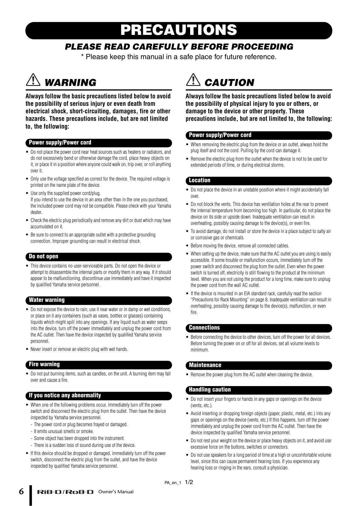
PRECAUTIONS
PLEASE READ CAREFULLY BEFORE PROCEEDING
- Please keep this manual in a safe place for future reference.

WARNING
Always follow the basic precautions listed below to avoid the possibility of serious injury or even death from electrical shock, short-circuiting, damages, fire or other hazards. These precautions include, but are not limited to, the following:
Power supply/Power cord
- Do not place the power cord near heat sources such as heaters or radiators, and do not excessively bend or otherwise damage the cord, place heavy objects on it, or place it in a position where anyone could walk on, trip over, or roll anything over it.
- Only use the voltage specified as correct for the device. The required voltage is printed on the name plate of the device.
- Use only the supplied power cord/plug. If you intend to use the device in an area other than in the one you purchased, the included power cord may not be compatible. Please check with your Yamaha dealer.
- Check the electric plug periodically and remove any dirt or dust which may have accumulated on it.
- Be sure to connect to an appropriate outlet with a protective grounding connection. Improper grounding can result in electrical shock.
Do not open
- This device contains no user-serviceable parts. Do not open the device or attempt to disassemble the internal parts or modify them in any way. If it should appear to be malfunctioning, discontinue use immediately and have it inspected by qualified Yamaha service personnel.
Water warning
- Do not expose the device to rain, use it near water or in damp or wet conditions, or place on it any containers (such as vases, bottles or glasses) containing liquids which might spill into any openings. If any liquid such as water seeps into the device, turn off the power immediately and unplug the power cord from the AC outlet. Then have the device inspected by qualified Yamaha service personnel.
- Never insert or remove an electric plug with wet hands.
Fire warning
- Do not put burning items, such as candles, on the unit. A burning item may fall over and cause a fire.
If you notice any abnormality
- When one of the following problems occur, immediately turn off the power switch and disconnect the electric plug from the outlet. Then have the device inspected by Yamaha service personnel.
- The power cord or plug becomes frayed or damaged.
- It emits unusual smells or smoke.
- Some object has been dropped into the instrument.
- There is a sudden loss of sound during use of the device.
- If this device should be dropped or damaged, immediately turn off the power switch, disconnect the electric plug from the outlet, and have the device inspected by qualified Yamaha service personnel.

CAUTION
Always follow the basic precautions listed below to avoid the possibility of physical injury to you or others, or damage to the device or other property. These precautions include, but are not limited to, the following:
Power supply/Power cord
- When removing the electric plug from the device or an outlet, always hold the plug itself and not the cord. Pulling by the cord can damage it.
- Remove the electric plug from the outlet when the device is not to be used for extended periods of time, or during electrical storms.
Location
- Do not place the device in an unstable position where it might accidentally fall over.
- Do not block the vents. This device has ventilation holes at the rear to prevent the internal temperature from becoming too high. In particular, do not place the device on its side or upside down. Inadequate ventilation can result in overheating, possibly causing damage to the device(s), or even fire.
- To avoid damage, do not install or store the device in a place subject to salty air or corrosive gas or chemicals.
- Before moving the device, remove all connected cables.
- When setting up the device, make sure that the AC outlet you are using is easily accessible. If some trouble or malfunction occurs, immediately turn off the power switch and disconnect the plug from the outlet. Even when the power switch is turned off, electricity is still flowing to the product at the minimum level. When you are not using the product for a long time, make sure to unplug the power cord from the wall AC outlet.
- If the device is mounted in an EIA standard rack, carefully read the section "Precautions for Rack Mounting" on page 8. Inadequate ventilation can result in overheating, possibly causing damage to the device(s), malfunction, or even fire.
Connections
- Before connecting the device to other devices, turn off the power for all devices. Before turning the power on or off for all devices, set all volume levels to minimum.
Maintenance
- Remove the power plug from the AC outlet when cleaning the device.
Handling caution
- Do not insert your fingers or hands in any gaps or openings on the device (vents, etc.).
- Avoid inserting or dropping foreign objects (paper, plastic, metal, etc.) into any gaps or openings on the device (vents, etc.) If this happens, turn off the power immediately and unplug the power cord from the AC outlet. Then have the device inspected by qualified Yamaha service personnel.
- Do not rest your weight on the device or place heavy objects on it, and avoid use excessive force on the buttons, switches or connectors.
- Do not use speakers for a long period of time at a high or uncomfortable volume level, since this can cause permanent hearing loss. If you experience any hearing loss or ringing in the ears, consult a physician.
Yamaha cannot be held responsible for damage caused by improper use or modifications to the device, or data that is lost or destroyed.
NOTICE
To avoid the possibility of malfunction/ damage to the product, damage to data, or damage to other property, follow the notices below.
Handling and Maintenance
- Do not use the device in the vicinity of a TV, radio, stereo equipment, mobile phone, or other electric devices. Otherwise, the device, TV, or radio may generate noise.
- Do not expose the device to excessive dust or vibrations, or extreme cold or heat (such as in direct sunlight, near a heater, or in a car during the day) to prevent the possibility of panel disfiguration, damage to the internal components or unstable operation.
- Do not place vinyl, plastic or rubber objects on the device, since this might discolor the panel or keyboard.
- When cleaning the device, use a dry and soft cloth. Do not use paint thinners, solvents, cleaning fluids, or chemical-impregnated wiping cloths.
- Condensation can occur in the device due to rapid, drastic changes in ambient temperature—when the device is moved from one location to another, or air conditioning is turned on or off, for example. Using the device while condensation is present can cause damage. If there is reason to believe that condensation might have occurred, leave the device for several hours without turning on the power until the condensation has completely dried out.
Always turn the power off when the device is not in use.
Connectors
- XLR-type connectors are wired as follows (IEC60268 standard): pin 1: ground, pin 2: hot (+), and pin 3: cold (-).
Information
About copyrights
- Copying of the commercially available musical data including but not limited to MIDI data and/or audio data is strictly prohibited except for your personal use.
About this manual
- The illustrations and LCD screens as shown in this manual are for instructional purposes only, and may appear somewhat different from those on your device.
- The company names and product names in this manual are the trademarks or registered trademarks of their respective companies.
- Specifications and exterior appearance may be subject to change without prior notice as a result of improvements.
European Models
Inrush Current based on EN 55103-1:2009
2A (on initial switch-on)
2A (after a supply interruption of 5s)
Conforms to Environments: E1, E2, E3 and E4
Information for Users on Collection and Disposal of Old Equipment

This symbol on the products, packaging, and/or accompanying documents means that used electrical and electronic products should not be mixed with general household waste.
For proper treatment, recovery and recycling of old products, please take them to applicable collection points, in accordance with your national legislation and the Directives 2002/96/EC.
By disposing of these products correctly, you will help to save valuable resources and prevent any potential negative effects on human health and the environment which could otherwise arise from inappropriate waste handling.
For more information about collection and recycling of old products, please contact your local municipality, your waste disposal service or the point of sale where you purchased the items.
[For business users in the European Union]
If you wish to discard electrical and electronic equipment, please contact your dealer or supplier for further information.
[Information on Disposal in other Countries outside the European Union]
This symbol is only valid in the European Union. If you wish to discard these items, please contact your local authorities or dealer and ask for the correct method of disposal.
(weee_eu)
Introduction
Thank you for choosing the Yamaha Input Rack Ri8-D/ Output Rack Ro8-D.
The Ri8-D is a Dante-compatible input rack equipped with 8 channels analog input. The Ro8-D is a Dante-compatible output rack equipped with 8 channels analog output.
To take full advantage of the superior functions and performance offered by the Ri8-D/Ro8-D, and to extend the useful life of the product, be sure to read this owner's manual carefully before operation.
Features
Long-distance Dante Network Capability
Low-latency, low-jitter audio can be transferred over distances up to 100 meters* between devices via standard Ethernet cables using the Dante network protocol. The Ri8-D/Ro8-D can be used as a general-purpose I/O box for the Dante network. Supported sampling rates are 44.1 kHz, 48 kHz, 88.2 kHz, and 96 kHz.
- Maximum practical distance may vary according to the cable used.
Vast variety of layout is available with compact 1U chassis
The Ri8-D is dedicated for input rack and the Ro8-D is for output. This enables an installation of rack for an occasion requires input only or output only.
Of course, combination with the Rio3224-D/Rio1608-D (input/output rack) is enabled to realize system configuration with higher flexibility.
Remotely Controllable Internal Head Amplifiers (Ri8-D only)
Internal head amplifier parameters can be remotely controlled from a compatible device.
Gain Compensation Function (Ri8-D only)
Enabling Gain Compensation feature of the Ri8-D for supporting equipment with gain compensation capability such as CL Series products may compensate change of analog gain in downstream by the compensation gain integrated in the Ri8-D, and it will send the audio signal to Dante network with gain level fixed to a value immediately before it was enabled.
Direct Audio In/Out With a Connected Computer
Connecting the Ri8-D/Ro8-D with a standard Ethernet cable to a computer that has a Dante Virtual Soundcard installed enables you to directly input or output audio signals without using an audio interface device (the Ri8-D is for input and the Ro8-D is for output only).
Firmware Updates
This product enables you to update the unit firmware to improve operations, add functions, and correct possible malfunctions. The following two types of firmware are available for the unit.
Unit's firmware
Dante module firmware
You must update each type of firmware separately.
Details on updating the firmware are available on the following website:
http://www.yamahaproaudio.com/
For information on updating and setting up the unit, please refer to the firmware update guide available on the website.
NOTE
When you update Dante firmware on the unit, be sure to update Dante firmware on other Dante-compatible devices connected to the Ri8-D/Ro8-D.
Precautions for Rack Mounting
This unit is rated for operation at ambient temperatures ranging from 0 to 40 degrees Celsius. When mounting the unit with other Ri8-D/Ro8-D unit(s) or other device(s) in an EIA standard equipment rack, internal temperatures can exceed the specified upper limit, resulting in impaired performance or failure. When rack mounting the unit, always observe the following requirements to avoid heat buildup:
- When mounting the unit in a rack with devices such as power amplifiers that generate a significant amount of heat, leave more than 1U of space between the Ri8-D/Ro8-D and other equipment. Also either leave the open spaces uncovered or install appropriate ventilating panels to minimize the possibility of heat buildup.
- To ensure sufficient airflow, leave the rear of the rack open and position it at least 10 centimeters from walls or other surfaces. If the rear of the rack can't be left open, install a commercially available fan or similar ventilating option to secure sufficient airflow. If you've installed a fan kit, there may be cases in which closing the rear of the rack will produce a greater cooling effect. Refer to the rack and/or fan unit manual for details.
About Dante
This product features Dante technology as a protocol to transmit audio signals. Dante is a network protocol developed by Audinate. It is designed to deliver multi-channel audio signals at various sampling and bit rates, as well as device control signals over a Giga-bit Ethernet (GbE) network. Dante also offers the following benefits:
- It transmits up to 512 in/512 out, for a total 1024 channels (in theory) of audio over a GbE network. (The Ri8-D features 8 in with a 24/32-bit resolution. The Ro8-D features 8 out with a 24/32-bit resolution.)
- Dante-enabled devices will automatically configure their network interfaces and find each other on the network. You can label Dante devices and their audio channels with names that make sense to you.
- Dante uses high accuracy network synchronization standards to achieve sample-accurate playback with extremely low latency and jitter. Four types of latency are available on the Ri8-D/Ro8-D: 0.25 msec, 0.5 msec, 1.0 msec, and 5.0 msec.
- Dante supports redundant connections via primary and secondary networks to defend against unforeseen difficulties.
- Connecting a computer to Dante network over Ethernet enables you to directly input or output audio signals without using any audio interface devices.
By taking advantages of these benefits, you can skip any complicated procedures to automate connections and setups of Dante-enabled devices, remotely control I/O racks or amplifiers from a mixing console, or make multi-track recordings to a DAW, such as Nuendo, installed on a computer in the network.
Visit Audinate website for more details on Dante.
http://www.audinate.com/
More information on Dante is also posted on the Yamaha Pro Audio website:
http://www.yamahaproaudio.com/
Controls and Functions
Front Panel

(1) [INPUT] Connectors 1-8 (Ri8-D only)
These are the XLR-3-31 type analog balanced connectors for the input channels. The input level range is from -62dBu to +10dBu . +48V phantom power can be supplied to devices that require it via the input connectors.
NOTE
The PAD will be switched on or off internally when the gain of the internal head amp is adjusted between +17 dB and +18 dB. Keep in mind that noise may be generated if there is a difference between the Hot and Cold impedance of the external device connected to the INPUT connector when using phantom power.
② OUTPUT +4 dBu Connectors 1-8 (Ro8-D only)
These XLR-3-32 type balanced connectors deliver analog output from the unit's corresponding output channels. Nominal output level is +4 dBu.
(3) [+48V] Indicators (Ri8-D only)
These indicators light when +48V phantom power is turned ON for the corresponding input channels. Phantom power supply switching can be carried out from a compatible digital mixing console or computer application. No phantom power will be supplied, however, if the [+48V MASTER] switch is OFF, even if phantom power to individual channels is turned ON (the +48V indicators will still light). The +48V indicators also function as error indicators: the indicators for all channels will flash if an error occurs.
CAUTION:
- Make sure that phantom power is turned OFF unless it is needed.
- When turning phantom power ON, make sure that no equipment other than phantom-powered devices such as condenser microphones are connected to the corresponding [INPUT] connectors. Applying phantom power to a device that does not require phantom power can damage the connected device.
- Do not connect or disconnect a device to an INPUT while phantom power is applied. Doing so can damage the connected device and/or the unit itself.
- To prevent possible damage to speakers, make sure that power amplifiers and/or powered speakers are turned OFF when switching phantom power ON or OFF. We also recommend setting all digital mixing console output
controls to minimum when turning phantom power ON or OFF. Sudden high level peaks caused by the switching operation can damage equipment as well as the hearing of those present.
(4) [PEAK] Indicators (Ri8-D only)
These indicators light red when the signal level of the corresponding channel reaches or exceeds -3 dBFS. The PEAK indicators also function as error indicators: the indicators for all channels will flash if an error occurs.
⑤ [SIG] (Signal) Indicators
These indicators light green when the signal applied to the corresponding channel reaches or exceeds -34 dBFS.
The SIG indicators also function as error indicators: the indicators for all channels will flash if an error occurs.
(6) [UNIT ID] Rotary Switch
This rotary switch enables you to set an ID number so that connected devices will recognize the Ri8-D/Ro8-D. The UNIT ID must be a unique number in the network so that the Ri8-D/Ro8-D will be able to transmit and receive audio signals over a Dante network, or be controlled from a connected digital mixing console.
Use the rotary switch while the power to the unit is turned OFF. Otherwise, the ID setting will not be effective.
⑦ [SYSTEM] Indicators
These indicators show the Ri8-D/Ro8-D's operating status. If the green indicator lights steadily and the red indicator turns off, the unit is operating normally.
When power to the unit is turned ON, if the green indicator turns off, or if the red indicator lights or flashes, the unit is not functioning properly. In this case, refer to the "Messages" section (see page 18).
⑧ [SYNC] Indicators
These indicators show the operating status of the Ri8-D/Ro8-D's internal Dante network capability. If the green indicator lights, the unit is operating as a word clock slave and synching to the word clock.
If the green indicator flashes, the unit is operating as the word clock master.
If the power to the unit is turned on but the green indicator is turned off, the unit is not functioning properly. In this case, refer to the "Messages" section (see page 18).
If the orange indicator lights or flashes, refer to the "Messages" section.
⑨ DIP Switches
These switches enable you to specify the settings related to the startup operation of the unit.
Set the DIP switches while the power to the unit is turned OFF. Otherwise, the setting will not be effective.
Refer to the following for details.
| Switch | Status |
| □ | Represent a status with switch toggled up. |
| ■ | Represent a status with switch toggled down. |
- Switch 1 (UNIT ID)
This switch setting determines whether the hexadecimal setting of the [UNIT ID] rotary switch will range from 0 to F (0 to 15) or from 10 to 1F (16 to 31).
| Switch | Setting | Description |
| 1 | UNIT ID ranging from 0 to F | The setting range of the [UNIT ID] rotary switch is from 0 to F. |
| 1 | UNIT ID ranging from 10 to 1F | The setting range of the [UNIT ID] rotary switch is from 10 to 1F. |
- Switch 4 (SECONDARY PORT)
This switch setting determines whether the rear-panel [SECONDARY] connector will be used for a daisy chain or redundant network.
With the [DAISY CHAIN] setting, you can connect multiple Dante-enabled network devices in a daisy chain without using a network switch. Refer to "Daisy Chain Network" in the "About Connections" section (see page 14) for more information about daisy chain connections.
With the [REDUNDANT] setting, the [PRIMARY] connector will be used for primary connections, and the [SECONDARY] connector will be used for secondary (backup) connections. If the unit is unable to transmit signals through the [PRIMARY] connector for some reason (e.g., due to damage or accidental removal of the cable, or a failed network switch), the [SECONDARY] connector will automatically take over communications and functions on the redundant network. Refer to "About Redundant Networks" in the "About Connections" section (see page 14) for more information on redundant networks.
| Switch | Setting | Description |
| 4 | DAISY CHAIN | The [SECONDARY] connector is used for a daisy chain connection. It can be connected in a daisy chain by connecting to [PRIMARY] terminal of the next device. |
| 4 | REDUNDANT | The [SECONDARY] connector is used for a redundant network. It will function as backup connection, independent of the network to which the [PRIMARY] connector is connected. |
- Switches 5 and 6 (REMOTE) (Ri8-D only)
When you plan to monitor or control the Ri8-D from a digital mixing console, these switches determine whether to use an Ri8-D-native compatible device such as CL Series or a non-Ri8-D-native device such as M7CL Series. Information on which devices feature Ri8-D-native support is available at the Yamaha pro audio website product page:
http://www.yamahaproaudio.com/products/
| Switch | Setting | Description |
| 56 | NATIVE | An Ri8-D-native device will control the Ri8-D. |
| 56 | AD8HR | A non-Ri8-D-native device will control the Ri8-D as AD8HRs. Set the UNIT ID number between 1 and F. The unit with any other UNIT ID numbers will not be controllable. |
- Switches 7 and 8 (START UP MODE)
These switches determine whether part of the internal memory is initialized when the unit starts up, or uses the previous settings (i.e., settings used prior to the most recent power-off).
If you plan to connect an Ri8-D/Ro8-D-native device, such as a CL series product, set the switches to [REFRESH]. The Ri8-D/Ro8-D will not input or output audio until the connected
Ri8-D/Ro8-D-native device transmits its settings to the Ri8-D/Ro8-D, so that the Ri8-D/Ro8-D will not output audio accidentally.
| Switch | Setting | Description | |
| 78 | REFRESH | The Ri8-D/Ro8-D starts up with part of the internal memory initialized. The following settings are initialized. | |
| HA GAIN | -6 dB | ||
| +48V | OFF | ||
| HPF | OFF | ||
| HPF Freq | 80Hz | ||
| Gain Compensation | OFF | ||
| Dante Patch | OFF | ||
| 78 | RESUME | The unit starts up using the settings assigned prior to the most recent power-off. | |
[+48V MASTER] Switch (Ri8-D only)
This is the master switch for the unit's +48V phantom power supply.
If the [+48V MASTER] switch is off, no phantom power will be supplied to the unit's input connectors even if the individual input phantom power settings are ON. However, the [+48V] indicators will light on channels for which phantom power is turned ON even if the [+48V MASTER] switch is OFF.
⑪ Power Indicator
Lights when AC power to the unit is ON.
⑫ Power Switch (B)
Turns power to the unit ON or OFF.
CAUTIONS:
- Rapidly turning the unit on and off in succession can cause it to malfunction. After turning the unit off, wait for about 6 seconds before turning it on again.
- Even when the power switch is turned off, electricity is still flowing to the product at the minimum level. When you are not using the product for a long time, make sure to unplug the power cord from the wall AC outlet.
Rear Panel

⑬ AC IN Connector
Connect the supplied AC power cord here. First, connect the power cord to the device, then insert the power cord plug into the AC outlet.
The supplied power cord features a special latching mechanism (V-LOCK) to prevent the power cord from being accidentally disconnected. Connect the power cord by inserting the power cord fully until it is locked.
CAUTION:
Be sure to turn the power off before connecting or disconnecting the power cord. Press the latch button on the plug to disconnect the power cord.

[PRIMARY]/[SECONDARY] Connectors
The Ri8-D/Ro8-D can be connected to other Dante-compatible devices (such as a CL-series product) via these RJ45 connectors using standard Ethernet cables (CAT5e or better recommended).
If DIP switch 4 on the front panel is set upward (to DAISY CHAIN), audio signals coming into one of these connectors will be output from the other. Refer to "Daisy Chain Network" in the "About Connections" section (see page 14) for more information on daisy chain connections.
If DIP switch 4 on the front panel is set downward (to REDUNDANT), the [PRIMARY] connector will be used for primary connection, and the [SECONDARY] connector will be used for secondary (backup) connection. If the unit is unable to transmit signals through the [PRIMARY] connector for some reason (e.g., due to damage or accidental removal of the cable, or a failed network switch), the [SECONDARY] connector will automatically take over the connection. Refer to "About Redundant Networks" in the "About Connections" section (see page 14) for more information on redundant networks.
NOTE
- Use STP (shielded twisted pair) cable to prevent electromagnetic interference. Make sure that the metal parts of the plugs are electrically connected to the STP cable shield by conductive tape or comparable means.
- Connect only Dante-compatible devices or GbE-compatible devices (including a computer).
[LINK/ACT] Indicators
These indicators show the communication status of the [PRIMARY] and [SECONDARY] connectors. They flash fast if the Ethernet cables are connected properly.
[1G] Indicators
These indicators light when the Dante network is functioning as Giga-bit Ethernet.
⑦ Grounding screw
Grounding of chassis shall be sufficiently connected via a power supply cord as long as AC socket is grounded since the attached power supply cord is a triplex cable. In addition, connecting this screw to ground may prevent hum noise or interference noise.
About Connections
There are two ways to connect the Ri8-D/Ro8-D to a Dante network.
Daisy Chain Network
A daisy chain is a wiring scheme in which multiple devices are connected together in sequence. In this way, networking is simple and requires no network switches. This connection method is suitable for a simple system with a small number of devices.
However, if a large number of devices are connected, the latency value must be increased. Also, if a connection is broken in a daisy chain network, the signal flow is interrupted at that point and no signal will be transferred beyond that point.

Star Network
In a star network, each device is connected to a central network switch. Using a GbE-compatible network switch enables you to configure a wide-band, large-scale network. We recommend a network switch that features various functions to control and monitor the network (such as Qos, the ability to assign priority to data flows - e.g., clock synchronization or audio transmission on certain data circuits.)
With this topology, it is common to configure a redundant network so that an unexpected network problem will not affect any audio or otherwise stable communications.
About Redundant Networks
A redundant network consists of two circuits, a primary circuit and a secondary circuit. Normally, the network operates on the primary circuit. However, if the primary connection is broken, the secondary circuit will automatically take over communications. Therefore, using a redundant network with a star topology would increase communication stability relative to a daisy chain network.

About Dante Controller
Dante Controller is a software application that allows configuration and audio routing of Dante networks. Use this application if you plan to connect or set up Dante-enabled devices that do not feature Ri8-D/Ro8-D-native support. Please download the latest Dante Controller from the following website.
Please note that Dante Controller Version 3.2.1 or later supports Ri8-D/Ro8-D.
http://www.yamahaproaudio.com/
To run Dante Controller, a computer must feature a GbE-compatible Ethernet connector.
Refer to the Dante Controller owner's manual for details on Dante Controller.
In Dante Controller, make the following basic settings:
- [Network View] [Routing] I/O patching
- [Network View] [Clock Status] Word clock master setting
- [Device View] [Config] Sampling rate setting
Head Amp Control
The Ri8-D head amplifiers can be remotely controlled from a host device, such as a compatible Yamaha digital mixing console.
Control from an Ri8-D-native Device
The Ri8-D head amplifiers can be controlled remotely from an Ri8-D-native digital mixing console, such as a CL series product.
The connected Ri8-D-native device displays the model name and UNIT ID number of the corresponding Ri8-D unit to be controlled.
If you plan to connect a device that features Ri8-D-native support to monitor and control the head amplifiers, refer to the owner's manual for the corresponding device.
Control from a Device That Does Not Feature Ri8-D-Native Support
This section explains how to configure the Ri8-D settings that are required to control the Ri8-D as AD8HR units from a device that does not feature Ri8-D-native support.
NOTE
The following Yamaha non-Ri8-D-native devices enable you to control the Ri8-D as AD8HRs. Insert the Dante-MY16-AUD card which is a firmware controllable as AD8HR into the Mini-YGDAI slot for connection.
M7CL, LS9, DM1000, DM2000, PM5D/DSP5D, DME64N/24N
Setting the DIP Switches
While the power to the unit is off, flip DIP switch 5 down and DIP switch 6 up.

Setting the UNIT ID
Setting the Ri8-D in [AD8HR] will set UNIT ID as virtual ID (as AD8HR Device ID).
If you combine Rio3224-D or Rio1608-D or add an AD8HR or SB168-ES in the network, make sure that the IDs are all unique.
Set the Ri8-D correctly so that you can control it as AD8HRs. In addition, scene recall can be used to recall all head amplifier settings at once. Refer to the digital mixing console owner's manual for details on head amplifier control.
Head Amplifier Parameters That Can be Monitored and Controlled
| Parameter | Description |
| +48V | Turns +48V phantom power ON or OFF for each channel. |
| HA GAIN | Adjusts gain from -6 dB to 66 dB in 1-dB increments. |
| HPF | Turns the high-pass filter ON or OFF. |
| HPF FREQ | Adjusts the cutoff frequency of the high-pass filter (12 dB/Oct.) from 20 Hz to 600 Hz in 60 steps. |
| METER (Ri8-D-native device only) | Displays a level meter for each input channel. |
| Device ID | It displays Device ID 1-F (Device ID as AD8HR) assigned based on the UNIT ID. |
| +48V Master SW | Displays the [+48V MASTER] switch ON/OFF status of the +48V phantom power supply. |
| Gain Compensation (Ri8-D-native device only) | Turns the Gain Compensation ON or OFF. |
Troubleshooting
Troubleshooting
| Symptom | Cause | Possible Solution |
| The power won't turn on. The power indicator doesn't light. | The power cable is connected improperly. | Connect the power cable properly (see page 13). |
| The [POWER] switch is not turned ON. | Turn the [POWER] switch ON. If the power still will not come on, refer the problem to your Yamaha dealer. | |
| The unit is not receiving an input signal. | The input cables are not connected properly. | Connect the cables properly. |
| No signal is output from external devices. | Output a signal from the source device and make sure that the SIG indicators on the appropriate channels will light. | |
| The internal head amplifier gain is not set to an appropriate level. | Set the internal head amplifier gain to an appropriate level. | |
| The DIP switches are set to REFRESH, but the Ri8-D-native device has not started up. | Start the Ri8-D-native device to send the setting to the Ri8-D. | |
| The input level is too low. | A condenser microphone is connected. | Turn the [+48V MASTER] switch ON. |
| Turn phantom power for the corresponding channel(s) ON from the Ri8-D-native device. | ||
| The internal head amplifier gain is not set to an appropriate level. | Set the internal head amplifier gain to an appropriate level. | |
| No sound is heard. | The cables are not connected properly. | Connect the cables properly. |
| The DIP switches are set to REFRESH, but the Ro8-D-native device has not started up. | Start the Ro8-D-native device to send the setting to the Ro8-D. | |
| Output is muted. | Unmute the output on the Ro8-D-native device. | |
| The head amp cannot be controlled. | The Ri8-D has not been mounted on the RACK of the Ri8-D-native device. | Mount the Ri8-D on the RACK of the Ri8-D-native device. |
| Adjusting the internal head amp gain does not change the audio level. | The Gain Compensation function is turned on. | If you are not using the Gain Compensation function, turn it off. |
| Adjustment of the [UNIT ID] rotary switch or DIP switch settings seems to be ineffective. | You may have adjusted the setting while the power is ON. | Turn the power OFF, then change the setting. |
Messages
Errors, warnings, and certain other types of information are displayed via the Ri8-D/Ro8-D front panel indicators. Messages are also displayed in the Dante Controller Error Status field.
Each indicator lights or flashes as described below:
| No call-out | The indicator is off. |
| Light | The indicator remains lit steadily. |
| Flash | The indicator continues to flash. |
| Flash x2 | The indicator flashes twice cyclically. |
| Flash x3 | The indicator flashes three times cyclically. |
Error Messages
When an error occurs, the indicators for all channels will flash until the error is resolved, and the SYSTEM indicators will light and/or flash cyclically as shown in the chart below. In that case, repair is required. Contact your Yamaha dealer.
| SYSTEM Indicators | Description | Possible Solution |
| SYSTEM Flash x2 | An internal error has occurred. | The device has failed. Contact your Yamaha dealer for repair. |
| SYSTEM Flash x3 | The MAC address setting has been corrupted and no communication can occur via Dante. | |
| SYSTEM Light Flash x3 | The internal memory has been corrupted. | Use the front-panel DIP switches to set START UP MODE to REFRESH, then restart the unit. If the problem persists after setting START UP MODE back to RESUME, consult your Yamaha dealer. |
| SYSTEM Light | UNIT ID is not unique. | Set a unique UNIT ID number for the Dante network. |
| SYSTEM Flash | The DIP switches are not set correctly. | Check the DIP switch settings, and set them correctly. |
Warning Messages
The indicators will light and/or flash as shown until the cause is resolved.
| SYNC Indicators | Description | Possible Solution |
| SYNC Flash | The word clock is not set correctly. | Set the clock mas-ter and sampling frequency correctly on the Ri8-D/Ro8-D-native device or in Dante Controller. |
| SYNC Flash x2 | Dante Network circuit is broken. | Make sure that the Ethernet cables are not removed or short-circuited. |
| SYNC Flash x3 | Dante Network is wired incorrectly. (The devices are con- nected in a ring net- work, although the DAISY CHAIN setting has been selected, or they are connected in a daisy chain network, although the REDUN-DANT setting has been selected, etc.) | Make sure that the Ethernet cables are connected cor- rectly. |
| SYNC Light Light | A non-GbE-compatible device is con- nected. | Remove the non-GbE-compatible device from the Dante network. |
| SYNC Light Flash | The SECONDARY connector has taken over communications during redundant net- work operation. | Check the circuit connected to the PRIMARY connec- tor. |
| SYNC Light Flash x2 | An abnormality has occurred on the circuit connected to the SEC- ONDARY connector during redundant net- work operation. | Check the circuit connected to the SECONDARY con- nector. |
Information Messages
The indicators will remain lit and/or flashing cyclically to report the status.
| SYNC Indicators | Description | Possible Solution |
| SYNCLight | Synchronizing | Please wait until the unit synchron- nizes completely. It may take up to 45 seconds to syn- chronize com- pletely. |
| SYNCFlash Light or flash in different patterns | Operating as the word clock master | The unit is operat- ing as the word clock master. |
Specifications
General Specifications
| Sampling Frequency | External | 44.1kHz+4.1667%, +0.1%, -0.1%, -4.0% | ±200ppm |
| 48kHz+4.1667%, +0.1%, -0.1%, -4.0% | ±200ppm | ||
| 88.2kHz+4.1667%, +0.1%, -0.1%, -4.0% | ±200ppm | ||
| 96kHz+4.1667%, +0.1%, -0.1%, -4.0% | ±200ppm | ||
| Signal Delay | Less than 3msINPUT to OUTPUT*, connect with CL5 using Dante, Dante Receive Latency set to 0.25ms (one way), Fs= 48kHz | ||
| Frequency Response | +0.5, -1.5dB 20Hz-20kHz, refer to +4dBu output @1kHz, INPUT to OUTPUT*, Fs= 44.1kHz, 48kHz+0.5, -1.5dB 20Hz-40kHz, refer to +4dBu output @1kHz, INPUT to OUTPUT*, Fs= 88.2kHz, 96kHz | ||
| Total Harmonic Distortion*2 | Less than 0.05% 20Hz-20kHz@+4dBu into 600Ω, Fs= 44.1kHz, 48kHzLess than 0.05% 20Hz-40kHz@+4dBu into 600Ω, Fs= 88.2kHz, 96kHzINPUT to OUTPUT*, Input Gain= Min. | ||
| Hum&Noise*3 | -128dBu typ., Equivalent Input Noise, Input Gain= Max.-88dBu Residual output noise, ST master off. | ||
| Dynamic Range | 112dB typ., DA Converter,108dB typ., INPUT to OUTPUT*, Input Gain= Min. | ||
| Crosstalk@1kHz | -100dB*, adjacent INPUT/OUTPUT channels, Input Gain= Min. | ||
| Dimensions (WxHxD) and Net Weight | Ri8-D: 480mm x 44mm x 362mm, 4.5kgRo8-D: 480mm x 44mm x 359mm, 4.4kg | ||
| Power Requirements(wattage) | Ri8-D: 35WRo8-D: 35W | ||
| Power Requirements(voltage and hertz) | US/Canada: 120V 60HzJapan: 100V 50/60HzChina: 110-240V 50/60Korea: 220V 60HzOther: 110-240V 50/60Hz | ||
| Temperature Range | Operating temperature range: 0 - 40°CStorage temperature range: -20 - 60°C | ||
| Included Accessories | Owner's Manual, Power Cord | ||
1. INPUT to OUTPUT means Ri8-D INPUT to Ro8-D OUTPUT
2. Total Harmonic Distortion is measured with 18dB/octave filter @80kHz
3. Hum & Noise are measured with A-Weight filter.
4. Crosstalk is measured with a 30dB/octave filter @22kHz
Analog Input Characteristics (Ri8-D only)
| Input Terminals | GAIN | Actual Load Impedance | For Use With Nominal | Input Level | Connector | |
| Nominal | Max. before clip | |||||
| INPUT 1-8 | +66dB | 7.5kΩ | 50-600Ω Mics & 600Ω Lines | -62dBu (0.616mV) | -42dBu (6.16mV) | XLR-3-31 type (Balanced)*1 |
| -6dB | +10dBu (2.45V) | +30dBu (24.5V) | ||||
1. XLR-3-31 type connectors are balanced.(1=GND, 2=HOT, 3=COLD)
In these specifications, 0dBu = 0.775 Vrms.
All input AD converters are 24bit linear, 128times oversampling.
+48V DC ( phantom power ) is supplied to INPUT XLR type connectors via each individual software controlled switch.
Analog Output Characteristics (Ro8-D only)
| Output Terminals | Actual Source Impedance | For Use With Nominal | Max.Output Level Select SW*1 | Output Level | Connector | |
| Nominal | Max. before clip | |||||
| OUTPUT 1-8 | 75Ω | 600Ω Lines | +24dB (default) | +4dBu (1.23 V) | +24dBu (12.3V) | XLR-3-32 type (Balanced)*2 |
| +18dB | -2dBu (616mV) | +18dBu (6.16V) | ||||
1. There are switches inside the body to preset the maximum output level.
2. XLR-3-32 type connectors are balanced. (1=GND, 2=HOT, 3=COLD)
* All output DA converters are 24bit, 128times oversampling.
Digital I/O Characteristics
| Terminals | Format | Data length | Level | Audio | Connector |
| Primary/Secondary | Dante | 24bit or 32bit | 1000Base-T | 8ch (Ri8-D to other device) 8ch (Other device to Ro8-D) | RJ45 |
Dimensions

Ri8-D


Ro8-D


Unit: mm
Important Notice: Guarantee Information for customers in European Economic Area (EEA) and Switzerland
| Important Notice: Guarantee Information for customers in EEA* and Switzerland For detailed guarantee information about this Yamaha product, and Pan-EEA* and Switzerland warranty service, please either visit the website address below (Printable file is available at our website) or contact the Yamaha representative office for your country. * EEA: European Economic Area | ||||||||
| Wichtiger Hinweis: Garantie-Information für Kunden in der EWR* und der Schweiz Fürnahme Garantie-Informatique über desses Produkt von Yamaha, sowie über den Pan-EWR* und Schweizer Garantieservice, besuchen Sieitte entweder die folgenden angegebene Internetadresses (eine druckfähige Version befindet sich auf unserer Seiten), oder wenden Sie sich an den für Ihr land zuständigen Yamaha-Vertrieb. * EWR: Europäischer Wirtschaftswärme | ||||||||
| Remarque importante: informations de garantie pour les clients de l'EEA et la Suisse Pour des informations plus détaillées sur la garantie de ce produit Yamaha et sur le service de garantie applicable dans l'ensemble de l'EEA ainsi qu'en Suisse, consultez notre site Web à l'adres ci-dessus (le fichier imprimable est disponible sur notre site Web) ou contactez directement Yamaha dans vos pays de résidence. * EEE: Espace Economique Européen | ||||||||
| Belangrête mecedeling: Garantie-informatique voor klanten in de EER* en Zwitserland Voor gedetaillede garantie-informatie over dit Yamaha-producte en de garantieservice in heel de EER* en Zwitserland, gaat u naar de onderstaande website (u vind een afdrukbaar bestand op unsere website) of neemt u contact met de vertegenwoordiging van Yamaha in uw land. * EER: Europesche Economische Rumme | ||||||||
| Avisio importante: information sobre la garantia para los clients de l'EEA* y Suza Para una información detallada sobre este produits Yamaha y sobre el soporte de garantía en la zona EEE* y Suza, visite la Directions web que se incluye más bajo (la version del archivo para imprimir esta disponible en nuestro Sitio web) o póngase en contacto con el representante de Yamaha en su pays. * EEE: Espacio Económico Europeo | ||||||||
| Bolangrijke mecedeling: Garantie-informatique Voorklanten in de EER* en Zwitserland, gaat u naar de onderstaande website (u vind een afdrukbaar bestand op unsere website) of neemt u contact met de vertegenwoordiging van Yamaha in uw land. * EER: Europesche Economische Rumme | ||||||||
| Avisio importante: informations sulla garantia para los clients de l'EEA* y Suza Per informationi dettaglale sulla garantia relative a quello prodotto Yamaha e Fassistenza in garanzia nei paesi EEA* e in Swizzera, potete consultare il site Web all'indirizzo rportato di seguito (è disponibile il file in formato stampabile) oppure contattare l'ufficio di rappresentazione locale della Yamaha. * EEA: Area Economica Europea | ||||||||
| Avisio importante: informations sobre as garantias para clients de AEE* e da Suza Para tener una informazione tornaperonizzada sobre este produits da Yamaha y sobre o service de garantia na EEE* e na Suza, visite o site a seguir (o arquivo para impressão está dispiñavel no loro site) ou entre em contacto com o escrétrico de representation da Yamaha no seu pays. * AEE: Area Económica Europaia | ||||||||
| Σημντή Σημεισόν Πλυροφορίες ευγύπους για τοῦ Διατές στον ΕΟΧ* και Ελβείσια Για λλτίαρες Σλροφορίες ευγύπους σχεπά με το τρόν προίου τός Σγελίας τοῦ ΕΟχ* και Ελβείσια επικερείτετη τὸν ΕΟχ* και Ελβείσια επικερείτετη τὸν τραρατάτω Ποτιολίδα (Ekτυμομίη μρρρίενινα διδεδίμουσι Οτήν Ειθελία βας) έτιανυνυθέτε έτην αντρομούπει τός Μγαγα έχροσας * * EOO: Eupmaikókos Okovopikóos Xúpóos | ||||||||
| Viktigt: Garantiinformation für kunder i EES-omradet'och Schweiz Förder detailerad information on ditta Yamahaprodukt samt garantiiservice i hela EES-omradet'och Schweiz kan du antingen besöka nedanstänstende webbadaddress (en utskriftsvänlig fil finns på webplatsen) eller kontakte Yamahas officiella représentant i ditt land. * EES: Europeiska Ekonomiska Samarbetsomradet | ||||||||
| Viktig merknad: Garantiinformationsonkunder i EOS* og Sveits Detaljert garantiinformationsondette Yamaha-produktet agarantiense for heile EOS-omradet'og Sveits kan fás enten v ad besekte nettadressen nedenfor (utskriftsservion finnes à vigre nettsider) et al. Kontakte Sontake Yamahas officiella représentant i ditt land. * EOS: Det europeske ökonomiske samarbeidsomradet | ||||||||
| Vigtig oplysning: Garantiopsyninger til kunder i EEO* og Schweiz De danke finde detailerade garantiopsyninger on ditta Yamaha-produkt on den failles garantiesserviceordering for EOO* (og Schweiz) ved at besage det websted, der er angivet nederfor (darfindes en fil, somkan odukstriv, pares websted), eller ved at kontakte Yamahas nationale représentationskontorl i det land, hvor De bor. * EOO: Det Europeske Ökonomiske Omrade Tärkä Ilmoitus: Takuutiedot Europanal talousalueen (EMA)* ja Sveitsin asiakaille Tämän Yamaha-tuutente sekä EMEA-aluen te Sveitsin taktuka koskevat yksityskohaisiet tiedod tot saatte alla olevasta nettiosoitteesta. (Tulostettava tiedosto saatavissa sivustollamme.) Voitte myös ottaa yhtyttä paikalliseen Yamaha-edustajaan. *ETA: Europan talousalue | ||||||||
| Wazne: Warunki garancjyne obowiazujace w EOG* i Szwajcari Aby doviedzie sieantiago na temar warunkow garancjyne偿还igo produkt firmy Yamaha i serwiswu garancjinyego w calym EOG* i Szwajcari, nalezdy odiewicz wskazana ponijei strone internetotwora (PIK gotawy do wydruku znajdujie sie na naszej stronie internetotwe) lub skontaktowac sie z prydstawcielstwem firmy Yamaha w goim kraju. * EOG - Europaqi Obszar Gospodarczy | ||||||||
| Duležite oznámieni: Záručni informace pro zákovázní y EHO* a ve Švycarsku Podrobné záručni informace o toto produkt Yamaha a záručnim servuis v celém EHO* a ve Švycarsku naleznete na niže udvené nebove adrese (soubor k tisku je dostupny na našich webovych strankách) nebu mezièle obrát in zastupeni firmy Yamaha ve své zemi. * EGO: Evopyski hospodárský prostor | ||||||||
| Fontos figyelmeztetis: Garancjina-ong EGT teruletén é Svájcban eló vasárlók szármára A jelen Yamaha termekre vanatkozó részlétjes garancjina-ong EGT reprente induse cohata, kūlastage palun veebisaiti alljärgneval addressil (meie sadidl on saadalv prinditav fali) vovi põrduge Teie regiooni Yamaha esinduse pleone. * EGT: Europai Gazdasagi Térseg | ||||||||
| Ouline markus: Garantiiteave Euroopa Majanduspirkkona (EMP*) ja Šveitsi kliidentele Täppe taeba te aaamiseks sellée Yamaha toto gentuki ning kogu Oumaopa Majanduspirkkona J SvětsiGarantiitenininduse kohta, kūlastage palun veebisaiti alljärgneval addressil (meie sadidl on saadalv prinditav fali) vovi põrduge Teie regiooni Yamaha esinduse pleone. * EGP: Europaqa Majanduspirkond | ||||||||
| Svarigs pazinojums: garantijs informacijs klientiem EEO* un Šveicé Lai sānemu t delaizitàu garantijs informacijs per so Šyama haukačuta kä, ari garantijas apkalpošanu EEO* un Šveicie, lüdzu, apmekljet jemit zemk odàrdito imekja vintes adresi (tímekla jvietne ir piejams drukajāms fails) vai sazinieties ar jusu valsti akpalpojóu Yamaha pärstvänciebu. * EEO: Europas Ekonomikas zona | ||||||||
| Démiso: informaciçă del garantijs pirekijems EEO* i Šveiciarjó Jei reiklia issamios informacjos apie SJ, 'Yamaha' produkt i je technine prieziúra visoje EEO* i Šveiciarjó, apsilankykite mûsu svatniéte johé V EEO -Europes ekonomie erdve | ||||||||
| Dolžite upozomeni: Informació o zárukce pre zázkaznikov v EHO* a Švajciarsku Podrobné informació o zárukce su toto produkt o spolocnosti Yamaha a garancjónom service v EHO* a Švajciarsku nájdelete na webovoj stránke uvedenej nižsie (na našej webovoj stránke je k disipzicii subr na tlač) alebo sa obrute na zastupcu spolocnosti Yamaha vo svojej krajine. * EHP: Europyski hospodársky priestor | ||||||||
| Pomembno obvestilo: Informació o garanciji za kupce v EGO* in Švici Za podobre sensione que informació o tem Yamaheim idelteklor gerancjşem servis v celoton nem EGO in Švici, običité splotneo moote, ki je navedeno spodaj (natisjiva datoteke je na voljo na našem spletné mestu), als obrnite na Yamahinegrednaya predstavnika v slovj dižav. * EGP: Evropski gospodarski prostdor | ||||||||
| Baxno Stoboume: Indropopmua 3a Knuhentn b EINI* b IIeivzucarpin 3a no podobna Infcpormua 3a rapaunianita 3a konhentn b EINI* b IIeivzucarpin 3a no podobna Infcpormua 3a rapaunianita 3a konhuchanov 3a konh. Incepuere napiya napiya napiya napiya napiya napiya napiya napiya napiya napiya napiya napiya napiya napiya napiya napiya napiya napiya napiya napiya napiya napiya napiya napiya napiya napiya napiya napiya napiya napiya napiya napiya napiya napiya 3a no podobna Infcpormua 3a rapaunianita 3a konhuchanov 3a konh. Incepuere napiya napiya napiya napiya napiya napiya napiya napiya napiya napiya napiya napiya napiya napiya napiya napiya napiya napiya napiya napiya nAPIYA 3a no podobna Infcpormua 3a rapaunianita 3a konhuchanov 3a konh. Incepuere napiya napiya napiya napiya napiya napiya napiya napiya napiya napiya napiya napiya napiya napiya napiya napiya napiya napiya napiya napiya napis 3a no podobna Infcpormua 3a rapaunianita 3a konhuchanov 3a konh. Incepuere napiya napiya napiya napiya napiya napiya napiya napiya napiya napiya napiya napiya napiya napiya napiya napiya napiya napiya napiya napiya napya napiya napiya napiya napiya napiya napiya napiya napiya napiya napiya napiya napiya napiya napiya napiya napiya napiya napiya napiya napiya napiya napiya napiya napiya napiya napiya napiya napiya napiya napiya napiya napiya napi YA 3a no podobna Infcpormua 3a rapaunianita 3a konhuchanov 3a konh. Incepuere napiya napiya napiya napiya napiya napiya napiya napiya napiya napiya napiya napiya napiya napiya napiya napiya napiya napiya napiya napiya nape 3a no podobna Infcpormua 3a rapaunianita 3a konhuchanov 3a konh. Incepuere napiya napiya napiya napiya napiya napiya napiya napiya napiya napiya napiya napiya napiya napiya napiya napiya napiya napiya napiya napiya nani 3a no podobna Infcpormua 3a rapaunianita 3a konhuchanov 3a konh. Incepuere napiya napiya napiya napiya napiya napiya napiya napiya napiya napiya napiya napiya napiya napiya napiya napiya napiya napiya napiya napiya napan 3a no podobna Infcpormua 3a rapaunianita 3a konhuchanov 3a konh. Incepuere napiya napiya napiya napiya napiya napiya napiya napiya napiya napiya napiya napiya napiya napiya napiya napiya napiya napiya napiya napiya nai 3a no podobna Infcpormua 3a rapaunianita 3a konhuchanov 3a konh. Incepuere napiya napiya napiya napiya napiya napiya napiya napiya napiya napiya napiya napiya napiya napiya napiya napiya napiya napiya napiya napiya naji 3a no podobna Infcpormua 3a rapaunianita 3a konhuchanov 3a konh. Incepuere napiya napiya napiya napiya napiya napiya napiya napiya napiya napiya napiya napiya napiya napiya napiya napiya napiya napiya napiya napiya nali 3a no podobna Infcpormua 3a rapaunianita 3a konhuchanov 3a konh. Incepuere napiya napiya napiya napiya napiya napiya napiya napiya napiya napiya napiya napiya napiya napiya napiya napiya napiya napiya napiya napiya nadi 3a no podobna Infcpormua 3a rapaunianita 3a konhuchanov 3a konh. Incepuere napiya napiya napiya napiya napiya napiya napiya napiya napiya napiya napiya napiya napiya napiya napiya napiya napiya napiya napiya napiya nati 3a no podobna Infcpormua 3a rapaunianita 3a konhuchanov 3a konh. Incepuere napiya napiya napiya napiya napiya napiya napiya napiya napiya napiya napiya napiya napiya napiya napiya napiya napiya napiya napiya napiya nasi 3a no podobna Infcpormua 3a rapaunianita 3a konhuchanov 3a konh. Incepuere napiya napiya napiya napiya napiya napiya napiya napiya napiya napiya napiya napiya napiya napiya napiya napiya napiya napiya napiya napiya navi 3a no podobna Infcpormua 3a rapaunianita 3a konhuchanov 3a konh. Incepuere napiya napiya napiya napiya napiya napiya napiya napiya napiya napiya napiya napiya napiya napiya napiya napiya napiya napiya napiya napiya nangi 3a no podobna Infcpormua 3a rapaunianita 3a konhuchanov 3a konh. Incepuere napiya napiya napiya napiya napiya napiya napiya napiya napiya napiya napiya napiya napiya napiya napiya napiya napiya napiya napiya napiya nipi 3a no podobna Infcpormua 3a rapaunianita 3a konhuchanov 3a konh. Incepuere napiya napiya napiya napiya napiya napiya napiya napiya napiya napiya napiya napiya napiya napiya napiya napiya napiya napiya napiya napiya nifi 3a no podobna Infcpormua 3a rapaunianita 3a konhuchanov 3a konh. Incepuere napiya napiya napiya napiya napiya napiya napiya napiya napiya napiya napiya napiya napiya napiya napiya napiya napiya napiya napiya napiya nini 3a no podobna Infcpormua 3a rapaunianita 3a konhuchanov 3a konh. Incepuere napiya napiya napiya napiya napiya napiya napiya napiya napiya napiya napiya napiya napiya napiya napiya napiya napiya napiya napiya napiya n api 3a no podobna Infcpormua 3a rapaunianita 3a konhuchanov 3a konh. Incepuere napiya napiya napiya napiya napiya napiya napiya napiya napiya napiya napiya napiya napiya napiya napiya napiya napiya napiya napiya napiya nopi 3a no podobna Infcpormua 3a rapaunianita 3a konhuchanov 3a konh. Incepuere napiya napiya napiya napiya napiya napiya napiya napiya napiya napiya napiya napiya napiya napiya napiya napiya napiya napiya napiya napiya noli 3a no podobna Infcpormua 3a rapaunianita 3a konhuchanov 3a konh. Incepuere napiya napiya napiya napiya napiya napiya napiya napiya napiya napiya napiya napiya napiya napiya napiya napiya napiya napiya napiya napiya nip 3a no podobna Infcpormua 3a rapaunianita 3a konhuchanov 3a konh. Incepuere napiya napiya napiya napiya napiya napiya napiya napiya napiya napiya napiya napiya napiya napiya napiya napiya napiya napiya napiya napiya nipe 3a no podobna Infcpormua 3a rapaunianita 3a konhuchanov 3a konh. Incepuere napiya napiya napiya napiya napiya napiya napiya napiya napiya napiya napiya napiya napiya napiya napiya napiya napiya napiya napiya napiya nane 3a no podobna Infcpormua 3a rapaunianita 3a konhuchanov 3a konh. Incepuere napiya napiya napiya napiya napiya napiya napiya napiya napiya napiya napiya napiya napiya napiya napiya napiya napiya napiya napiya napiya npi 3a no podobna Infcpormua 3a rapaunianita 3a konhuchanov 3a konh. Incepuere napiya napiya napiya napiya napiya napiya napiya napiya napiya napiya napiya napiya napiya napiya napiya napiya napiya napiya napiya napiya nabi 3a no podobna Infcpormua 3a rapaunianita 3a konhuchanov 3a konh. Incepuere napiya napiya napiya napiya napiya napiya napiya napiya napiya napiya napiya napiya napiya napiya napiya napiya napiya napiya napiya napiya nafi 3a no podobna Infcpormua 3a rapaunianita 3a konhuchanov 3a konh. Incepuere napiya napiya napiya napiya napiya napiya napiya napiya napiya napiya napiya napiya napiya napiya napiya napiya napiya napiya napiya napiya nandi 3a no podobna Infcpormua 3a rapaunianita 3a konhuchanov 3a konh. Incepuere napiya napiya napiya napiya napiya napiya napiya napiya napiya napiya napiya napiya napiya napiya napiya napiya napiya napiya napiya napiya niki 3a no podobna Infcpormua 3a rapaunianita 3a konhuchanov 3a konh. Incepuere napiya napiya napiya napiya napiya napiya napiya napiya napiya napiya napiya napiya napiya napiya napiya napiya napiya napiya napiya napiya nedi 3a no podobna Infcpormua 3a rapaunianita 3a konhuchanov 3a konh. Incepuere napiya napiya napiya napiya napiya napiya napiya napiya napiya napiya napiya napiya napiya napiya napiya napiya napiya napiya napiya napiya nami 3a no podobna Infcpormua 3a rapaunianita 3a konhuchanov 3a konh. Incepuere napiya napiya napiya napiya napiya napiya napiya napiya napiya napiya napiya napiya napiya napiya napiya napiya napiya napiya napiya napiya neni 3a no podobna Infcpormua 3a rapaunianita 3a konhuchanov 3a konh. Incepuere napiya napiya napiya napiya napiya napiya napiya napiya napiya napiya napiya napiya napiya napiya napiya napiya napiya napiya napiya napiya nni 3a no podobna Infcpormua 3a rapaunianita 3a konhuchanov 3a konh. Incepuere napiya napiya napiya napiya napiya napiya napiya napiya napiya napiya napiya napiya napiya napiya napiya napiya napiya napiya napiya napiya naise 3a no podobna Infcpormua 3a rapaunianita 3a konhuchanov 3a konh. Incepuere napiya napiya napiya napiya napiya napiya napiya napiya napiya napiya napiya napiya napiya napiya napiya napiya napiya napiya napiya napiya naside 3a no podobna Infcpormua 3a rapaunianita 3a konhuchanov 3a konh. Incepuere napiya napiya napiya napiya napiya napiya napiya napiya napiya napiya napiya napiya napiya napiya napiya napiya napiya napiya napiya napiya nide 3a no podobna Infcpormua 3a rapaunianita 3a konhuchanov 3a konh. Incepuere napiya napiya napiya napiya napiya napiya napiya napiya napiya napiya napiya napiya napiya napiya napiya napiya napiya 3a no podobna Infcpormua 3a rapaunianita 3a konhuchanov 3a konh. Incepuere napiya napiya napiya nani 3a no podobna Infcpormua 3a rapaunianita 3a konhuchanov 3a konh. Incepuere napiya napiya napiya nani 3a no podobna Infcpormua 3a rapaunianita 3a konhuchanov 3a konh. Incepuere napiya napiya nani 3a no podobna Infcpormua 3a rapaunianita 3a konhuchanov 3a konh. Incepuere napiya napiya nani 3a no podobna Infcpormua 3a rapaunianita 3a konhuchanov 3a konh. Incepuere napiya napiya nANI 3a no podobna Infcpormua 3a rapaunianita 3a konhuchanov 3a konh. Incepuere napiya napiya nani 3a no podobna Infcpormua 3a rapaunianita 3a konhuchanov 3a konh. Incepuere napiya napiya nani 3a no podobna INfcpormua 3a rapaunianita 3a konhuchanov 3a konh. Incepuere napiya napiya nani 3a no podobna Infcpormua 3a rapaunianita 3a konhuchanov 3a konh. Incepuere napiya napiya nani 3a no podobna Infcpormua 3a ranaynag | 3a no podobna Infcpormua 3a rapaunianita 3a konhuchanov 3a konh. Incepuere napiya napiya nani 3a no podobna Infcpormua 3a ranaynag | 3a no podobna Infcpormua 3a rapaunianita 3a konhuchanov 3a konh. Inces 3a no podobna Infcpormua 3a ranaynag | 3a no podobna Infcpormua 3a rapaunianita 3a konhuchanov 3a konh. Inces 3a no podobna Infcpormua 3a ranaynag | 3a no podobna Infcpormua 3a rapaunianita 3a konh.chudok 3a no podobna Infcpormua 3a ranaynag | 3a no podobna Infcpormua 3a rapaunianita 3a konh.chudok 3a no podobna Infcpormua 3a ranaynag | 3a no podobna Infcpormua 3a rapaunianita 3a konh.chudok 3a no podOBnInfcpormua 3a ranaynag | 3a no podobna Infcpormua 3a rapaunianita 3a konh.chudok 3a no podOBnInfcpormua 3a ranaynag | 3a no podobna Infcpormua 3a rapaunianita 3a konh.chudok 3a no podOBnInfcpormua 2014 3a no podOBnInfcpormua 2014 3a no podOBnInfcpormua 2014 3a no podOBnInfcpormua 2014 3a no podOBnInfcpormua 2014 3a no podOBnInfcpormua 2014 3a no podOBnInfcpormua 214 3a no podOBnInfcpormua 214 3a no podOBnInfcpormua 214 3a no podOBnInfcpormua 214 3a no podOBnInfcpormua 214 3a no podOBnInfcpormua 214 3a no podOBnInfcpormua 214 2014 3a no podOBnInfcpormua 214 3a no podOBnInfcpormua 214 3a no podOBnInfcpormua 214 3a no podOBnInfcpormua 214 3a no podOBnInfcpormua 214 3a no podOBnInfcpormua 215 3a no podOBnInfcpormua 215 3a no podOBnInfcpormua 215 3a no podOBnInfcpormua 215 3a no podOBnInfcpormua 215 3a no podOBnInfcpormua 215 3a no podOBnInfcpormua 215 3a No podOBnInfcpormua 215 3a No podOBnInfcpormua 215 3a No podOBnInfcpormua 215 3a No podOBnInfcpormua 215 3a No podOBnInfcpormua 215 3a No podOBnInfcpormua 215 3a No podOBnINfcpormua 215 3a No podOBnINfcpormua 215 3a No podOBnINfcpormua 215 3a No podOBnINfcpormua 215 3a No podOBnINfcpormua 215 3a No podOBnINfcpormua 215 3a No podOBnINfcpormUA 215 3a No podOBnINfcpormUA 215 3a No podOBnINfcpormUA 215 3a No podOBnINfcpormUA 215 3a No podOBnINfcpormUA 215 3a No podOBnINfcpormUA 215 3a No podOBnINfcpormUA 216 3a No podOBnINfcpormUA 216 3a No podOBnINfcpormUA 216 3a No podOBnINfcpormUA 216 3a No podOBnINfcpormUA 216 3a No podOBnINfcpormUA 216 3a No podOBnINfcpormUA 216 3aNo podOBnINfcpormUA 216 3a No podOBnINfcpormUA 216 3a No podOBnINfcpormUA 216 3a No podOBnINfcpormUA 216 3a No podOBnINfcpormUA 216 3a No podOBnINfcpormUA 216 3a No podOBn INfcpormUA 216 3a No podOBn INfcpormUA 216 3a No podOBn INfcpormUA 216 3a No podOBn INfcpormUA 216 3a No podOBn INfcpormUA 216 3a No podOBn INfcpormUA 216 3a No podOBn INfcporm UA 216 3a No podOBn INfcporm UA 216 3a No podOBn INfcporm UA 216 3a No podOBn INfcporm UA 216 3a No podOBn INfcporm UA 216 3a No podOBn INfcporm UA 216 3a No podOBn INfcporm UA 217 3a No podOBn INfcporm UA 217 3a No podOBn INfcporm UA 217 3a No podOBn INfcporm UA 217 3a No podOBn INfcporm UA 217 3a No podOBn INfcporm UA 217 3a No podOBn INfcporm UA 217 3aNo podOBn INfcporm UA 217 3a No podOBn INfcporm UA 217 3a No podOBn INfcporm UA 217 3a No podOBn INfcporm UA 217 3a No podOBn INfcporm UA 217 3a No podOBn INfcporm UA 217 3a No podOBnINfcporm UA 217 3a No podOBn INfcporm UA 217 3a No podOBn INfcporm UA 217 3a No podOBn INfcporm UA 217 3a No podOBn INfcporm UA 217 3a No podOBn INfcporm UA 217 3a No podOBn INfcporm UDA 217 3a No podOBn INfcporm UDA 217 3a No podOBn INfcporm UDA 217 3a No podOBn INfcporm UDA 217 3a No podOBn INfcporm UDA 217 3a No podOBn INfcporm UDA 217 3a No podOBn INfcporp M 217 3a No podOBn INfcporp M 217 3a No podOBn INfcporp M 217 3a No podOBn INfcporp M 217 3a No podOBn INfcporp M 217 3a No podOBn INfcporp M 217 3a No podOBn INfcporp M 218 3a No podOBn INfcporp M 218 3a No podOBn INfcporp M 218 3a No podOBn INfcporp M 218 3a No podOBn INfcporp M 218 3a No podOBn INfcporp M 218 3a No podOBn INfcporp M 218 3aNo podOBn INfcporp M 218 3a No podOBn INfcporp M 218 3a No podOBn INfcporp M 218 3a No podOBn INfcporp M 218 3a No podOBn INfcporp M 218 3a No podOBn INfcporp M 218 3a No podOBnINfcporp M 218 3a No podOBn INfcporp M 218 3a No podOBn INfcporp M 218 3a No podOBn INfcporp M 218 3a No podOBn INfcporp M 218 3a No podOBn INfcporp M 218 3a No podOBn INfcporpM 218 3a No podOBn INfcporp M 218 3a No podOBn INfcporp M 218 3a No podOBn INfcporp M 218 3a No podOBn INfcporp M 218 3a No podOBn INfcporp M 218 3a No podOBn INfcporp M 217 3a No podOBn INfcporp M 217 3a No podOBn INfcporp M 217 3a No podOBn INfcporp M 217 3a No podOBn INfcporp M 217 3a No podOBn INfcporp M 217 3aNo podOBn INfcporp M 217 3a No podOBn INfcporp M 217 3a No podOBn INfcporp M 217 3a No podOBn INfcporp M 217 3a No podOBn INfcporp M 217 3a No podOBn INfcporp M 217 3a No podOBnINfcporp M 217 3a No podOBn INfcporp M 217 3a No podOBn INfcporp M 217 3a No podOBn INfcporp M 217 3a No podOBn INfcporp M 217 3a No podOBn INfcporp M 217 3a No podOBn INfcporpM 217 3a No podOBn INfcporp M 217 3a No podOBn INfcporp M 217 3a No podOBn INfcporp M 217 3a No podOBn INfcporp M 217 3a No podOBn INfcporp M 217 3a No podOBn INfcporp M 216 3a No podOBn INfcporp M 216 3a No podOBn INfcporp M 216 3a No podOBn INfcporp M 216 3a No podOBn INfcporp M 216 3a No podOBn INfcporp M 216 3a No podOBn INfcporp M 216 3aNo podOBn INfcporp M 216 3a No podOBn INfcporp M 216 3a No podOBn INfcporp M 216 3a No podOBn INfcporp M 216 3a No podOBn INfcporp M 216 3a No podOBn INfcporp M 216 3a No podOBnINfcporp M 216 3a No podOBn INfcporp M 216 3a No podOBn INfcporp M 216 3a No podOBn INfcporp M 216 3a No podOBn INfcporp M 216 3a No podOBn INfcporp M 216 3a No podOBn INfcporpM 216 3a No podOBn INfcporp M 216 3a No podOBn INfcporp M 216 3a No podOBn INfcporp M 216 3a No podOBn INfcporp M 216 3a No podOBn INfcporp M 216 3a No podOBn INfcporp M 217 3a No podOBn INfciorp M 217 3a No podOBn INfciorp M 217 3a No podOBn INfciorp M 217 3a No podOBn INfciorp M 217 3a No podOBn INfciorp M 217 3a No podOBn INfciorp M 217 3a No podOBn INfciorp M 1999 3a No podOBn INfciorp M 217 3a No podOBn INfciorp M 217 3a No podOBn INfciorp M 217 3a No podOBn INfciorp M 217 3a No podOBn INfciorp M 217 3a No podOBn INfciorp M 217 3aNo podOBn INfciorp M 217 3a No podOBn INfciorp M 217 3a No podOBn INfciorp M 217 3a No podOBn INfciorp M 217 3a No podOBn INfciorp M 217 3a No podOBn INfciorp M 217 3a No podOBnINfciorp M 217 3a No podOBn INfciorp M 217 3a No podOBn INfciorp M 217 3a No podOBn INfciorp M 217 3a No podOBn INfciorp M 217 3a No podOBn INfciorp M 217 3a No podOBn INfciorpM 217 3a No podOBn INfciorp M 217 3a No podOBn INfciorp M 217 3a No podOBn INfciorp M 217 3a No podOBn INfciorp M 217 3a No podOBn INfciorp M 217 3a No podOBn INfciorp M 216 3a No podOBn INfciorp M 216 3a No podOBn INfciorp M 216 3a No podOBn INfciorp M 216 3a No podOBn INfciorp M 216 3a No podOBn INfciorp M 216 3a No podOBn INfciorp M 216 3aNo podOBn INfciorp M 216 3a No podOBn INfciorp M 216 3a No podOBn INfciorp M 216 3a No podOBn INfciorp M 216 3a No podOBn INfciorp M 216 3a No podOBn INfciorp M 216 3a No podOBnINfciorp M 216 3a No podOBn INfciorp M 216 3a No podOBn INfciorp M 216 3a No podOBn INfciorp M 216 3a No podOBn INfciorp M 216 3a No podOBn INfciorp M 216 3a No podOBn INfciorpM 216 3a No podOBn INfciorp M 216 3a No podOBn INfciorp M 216 3a No podOBn INfciorp M 216 3a No podOBn INfciorp M 216 3a No podOBn INfciorp M 216 3a No podOBn INfciorp M 217 3a No podOBn INfciorp M 217 3a No podOBn INfciorp M 217 3a No podOBn INfciorp M 217 3a No podOBn INfciorp M 217 3a No podOBn INfciorp M 217 3a Nod Pod OBn INfciorp M 217 3a No podOBn INfciorp M 217 3a No podOBn INfciorp M 217 3a No podOBn INfciorp M 217 3a No podOBn INfciorp M 217 3a No podOBn INfciorp M 217 3a No podOBn INfcorp M 217 3a No podOBn INfciorp M 217 3a No podOBn INfciorp M 217 3a No podOBn INfciorp M 217 3a No podOBn INfciorp M 217 3a No podOBn INfciorp M 217 3a No podOBn INfciorp M 51 3a No podOBn INfciorp M 51 3a No podOBn INfciorp M 51 3a No podOBn INfciorp M 51 3a No podOBn INfciorp M 51 3a No podOBn INfciorp M 51 3a No podOBn INfciorp M 51 3a No podOBn INfcorp M 51 3a No podOBn INfciorp M 51 3a No podOBn INfciorp M 51 3a No podOBn INfciorp M 51 3a No podOBn INfciorp M 51 3a No podOBn INfciorp M 51 3a No podOBn INfciorp M 51 3a No Pod OBn INfciorp M 51 3a No Pod OBn INfciorp M 51 3a No Pod OBn INfciorp M 51 3a No Pod OBn INfciorp M 51 3a No Pod OBn INfciorp M 51 3a No Pod OBn INfciorp M 51 3a No Pod OBn INfciorp M 51 |
For details of products, please contact your nearest Yamaha representative or the authorized distributor listed below.
Yamaha Canada Music Ltd.
135 Milner Avenue, Scarborough, Ontario,
M1S 3R1, Canada
Tel: 416-298-1311
U.S.A.
Yamaha Corporation of America
6600 Orangethorpe Ave., Buena Park, Calif. 90620,
U.S.A.
Tel: 714-522-9011
CENTRAL & SOUTH AMERICA
MEXICO
Yamaha de Mexico S.A. de C.V.
Col. San José Insurgentes, C.P. 03900,
Deleg. Benito Juarez, Mexico, D.F.
Tel: 55-5804-0600
BRAZIL
PANAMA AND OTHER LATIN
AMERICAN COUNTRIES/
CARIBBEAN COUNTRIES
Yamaha Music Latin America, S.A.
Torre Banco General, Piso 7, Urbanizacion Marbella,
Sherbourne Drive, Tilbrook, Milton Keynes,
MK7 8BL, England
Tel: 01908-366700
GERMANY
Yamaha Music Europe GmbH
Siemensstraße 22-34, 25462 Rellingen, Germany
Tel: 04101-3030
Branch Switzerland in Zurich
Seefeldstrasse 94, 8008 Zürich, Switzerland
Tel: 044-387-8080
AUSTRIA/BULGARIA
Yamaha Music Europe GmbH Branch Austria
Schleiergasse 20, A-1100 Wien, Austria
Tel: 01-60203900
CZECH REPUBLIC/HUNGARY/
ROMANIA/SLOVAKIA/SLOVENIA
Yamaha Music Europe GmbH
Branch Austria (Central Eastern Europe Office)
Schleiergasse 20, A-1100 Wien, Austria
Tel: 01-602039025
POLAND/LITHUANIA/LATVIA/ESTONIA
Yamaha Music Europe GmbH
Branch Poland Office
Yamaha Music Europe GmbH, Branch Italy
Viale Italia 88, 20020 Lainate (Milano), Italy
Tel: 02-935-771
SPAIN/PORTUGAL
Yamaha Music Europe GmbH Ibérica, Sucursal
en España
Ctra.de la Coruna km.17,200,28230
Las Rozas (Madrid), Spain
Tel: +34-902-39-8888
GREECE
Philippos Nakas S.A. The Music House
147 Skiathou Street, 112-55 Athens, Greece
Tel: 01-228 2160
SWEDEN/FINLAND/ICELAND
Yamaha Music Europe GmbH Germany filial
Scandinavia
J. A. Wettergrens Gata 1, Box 30053
S-400 43 Göteborg, Sweden
Tel: 031 89 34 00
DENMARK
Yamaha Music Europe GmbH, Tyskland - filial
Denmark
Generatorvej 6A, DK-2730 Herlev, Denmark
Tel: 44 92 49 00
NORWAY
Yamaha Music Europe GmbH Germany -
Norwegian Branch
Grini Næringspark 1, N-1345 Østerås, Norway
Tel: 67167770
RUSSIA
Yamaha Music (Russia)
Room 37, bld. 7, Kievskaya street, Moscow,
121059, Russia
Tel: 495 626 5005
OTHER EUROPEAN COUNTRIES
Yamaha Music Europe GmbH
Siemensstraße 22-34, 25462 Rellingen, Germany
Tel: +49-4101-3030
AFRICA
Yamaha Corporation,
Asia-Pacific Sales & Marketing Group
Nakazawa-cho 10-1, Naka-ku, Hamamatsu,
Japan 430-8650
Tel: +81-53-460-2303
MIDDLE EAST
TURKEY/CYPRUS
Yamaha Music Europe GmbH
Siemensstraße 22-34, 25462 Rellingen, Germany
Tel: 04101-3030
OTHER COUNTRIES
Yamaha Music Gulf FZE
LOB 16-513, P.O.Box 17328, Jubel Ali,
Dubai, United Arab Emirates
Tel: +971-4-881-5868
ASIA
THE PEOPLE'S REPUBLIC OF CHINA
Yamaha Music & Electronics (China) Co.,Ltd.
2F, Yunhedasha, 1818 Xinzha-lu, Jingan-qu,
Shanghai, China
Tel: 021-6247-2211
INDIA
Yamaha Music India Pvt. Ltd.
Spazedge building, Ground Floor, Tower A, Sector
47, Gurgaon- Sohna Road, Gurgaon, Haryana, India
Tel: 0124-485-3300
INDONESIA
PT. Yamaha Musik Indonesia (Distributor)
PT. Nusantik
Gedung Yamaha Music Center, Jalan Jend. Gatot
SubROTO Kav. 4, Jakarta 12930, Indonesia
Tel: 021-520-2577
KOREA
Yamaha Music Korea Ltd.
8F, 9F, Dongsung Bldg. 158-9 Samsung-Dong,
Kangnam-Gu, Seoul, Korea
Tel: 02-3467-3300
MALAYSIA
Yamaha Music (Malaysia) Sdn., Bhd.
Lot 8, Jalan Perbandaran, 47301 Kelana Jaya,
Petaling Jaya, Selangor, Malaysia
Tel: 03-78030900
SINGAPORE
Yamaha Music (Asia) PRIVATE LIMITED
Blk 202 Hougang Street 21, #02-00,
Singapore 530202, Singapore
Tel: 6747-4374
TAIWAN
Yamaha KHS Music Co., Ltd.
3F, #6, Sec.2, Nan Jing E. Rd. Taipei.
Taiwan 104, R.O.C.
Tel: 02-2511-8688
THAILAND
Siam Music Yamaha Co., Ltd.
4, 6, 15 and 16th floor, Siam Motors Building,
891/1 Rama 1 Road, Wangmai,
Pathumwan, Bangkok 10330, Thailand
Tel: 02-215-2622
OTHER ASIAN COUNTRIES
Yamaha Corporation,
Asia-Pacific Sales & Marketing Group
Nakazawa-cho 10-1, Naka-ku, Hamamatsu,
Japan 430-8650
Tel: +81-53-460-2303
OCEANIA
AUSTRALIA
Yamaha Music Australia Pty. Ltd.
Level 1, 99 Queensbridge Street, Southbank,
Victoria 3006, Australia
Tel: 3-9693-5111
COUNTRIES AND TRUST
TERRITORIES IN PACIFIC OCEAN
Yamaha Corporation,
Asia-Pacific Sales & Marketing Group
Nakazawa-cho 10-1, Naka-ku, Hamamatsu,
Japan 430-8650
Tel: +81-53-460-2303

YAMAHA
Yamaha Pro Audio Global Web Site
http://www.yamahaproaudio.com/
Yamaha Manual Library
© 2012 Yamaha Corporation
211PHD*. *-A0
Printed in China