DSR-118W - Subwoofer YAMAHA - Free user manual and instructions
Find the device manual for free DSR-118W YAMAHA in PDF.

| Product Type | Powered Subwoofer |
| Brand | YAMAHA |
| Model | DSR-118W |
| Speaker | 18 inches |
| Power Output | 700 W (RMS) |
| Frequency Response | 20 Hz - 120 Hz |
| Maximum SPL | 133 dB |
| Inputs | 2 x XLR-1/4" combo |
| Outputs | 1 x XLR (THRU) |
| Controls | Polarity (Normal/Invert), FRONT LED (Enable/Disable), Limiter, Protection |
| Power Supply | 100-240 V, 50/60 Hz |
| Dimensions (W x H x D) | 531 x 600 x 600 mm |
| Weight | 36 kg |
| Maintenance and Cleaning | Clean with a dry, soft cloth. Avoid chemical products. |
| Safety | Do not expose to water. Use a grounded outlet. Have repairs performed by a qualified technician. |
| Spare Parts and Repairability | Contact an authorized Yamaha dealer for original parts. |
| General Information | This subwoofer is part of the DSR series. It is designed for professional use. |
Frequently Asked Questions - DSR-118W YAMAHA
User questions about DSR-118W YAMAHA
0 question about this device. Answer the ones you know or ask your own.
Ask a new question about this device
Download the instructions for your Subwoofer in PDF format for free! Find your manual DSR-118W - YAMAHA and take your electronic device back in hand. On this page are published all the documents necessary for the use of your device. DSR-118W by YAMAHA.
USER MANUAL DSR-118W YAMAHA
natural_image
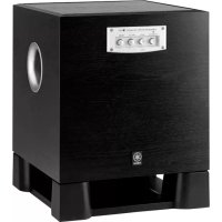
Four black Yamaha audio amplifiers arranged in a row, no visible text or symbols on the devices themselves.POWERED SPEAKERS DSR series
POWERED SPEAKER
The above warning is located on the rear of the unit.
Explanation of Graphical Symbols
The lightning flash with arrowhead symbol within an equilateral triangle is intended to alert the user to the presence of uninsulated “dangerous voltage” within the product’s enclosure that may be of sufficient magnitude to constitute a risk of electric shock to persons.

The exclamation point within an equilateral triangle is intended to alert the user to the presence of important operating and maintenance (servicing) instructions in the literature accompanying the product.
IMPORTANT SAFETY INSTRUCTIONS
1 Read these instructions.
2 Keep these instructions.
3 Heed all warnings.
4 Follow all instructions.
5 Do not use this apparatus near water.
6 Clean only with dry cloth.
7 Do not block any ventilation openings. Install in accordance with the manufacturer's instructions.
8 Do not install near any heat sources such as radiators, heat registers, stoves, or other apparatus (including amplifiers) that produce heat.
9 Do not defeat the safety purpose of the polarized or grounding-type plug. A polarized plug has two blades with one wider than the other. A grounding type plug has two blades and a third grounding prong. The wide blade or the third prong are provided for your safety. If the provided plug does not fit into your outlet, consult an electrician for replacement of the obsolete outlet.
10 Protect the power cord from being walked on or pinched particularly at plugs, convenience receptacles, and the point where they exit from the apparatus.
11 Only use attachments/accessories specified by the manufacturer.
12 Use only with the cart, stand, tripod, bracket, or table specified by the manufacturer, or sold with the apparatus. When a cart is used, use caution when moving the cart/apparatus combination to avoid injury from
13 Unplug this apparatus during lightning storms or when unused for long periods of time.
14 Refer all servicing to qualified service personnel. Servicing is required when the apparatus has been damaged in any way, such as power-supply cord or plug is damaged, liquid has been spilled or objects have fallen into the apparatus, the apparatus has been exposed to rain or moisture, does not operate normally, or has been dropped.

WARNING
TO REDUCE THE RISK OF FIRE OR ELECTRIC SHOCK, DO NOT EXPOSE THIS APPARATUS TO RAIN OR MOISTURE.
(UL60065_03)
FCC INFORMATION (U.S.A.)
- IMPORTANT NOTICE: DO NOT MODIFY THIS UNIT! This product, when installed as indicated in the instructions contained in this manual, meets FCC requirements. Modifications not expressly approved by Yamaha may void your authority, granted by the FCC, to use the product.
- IMPORTANT: When connecting this product to accessories and/or another product use only high quality shielded cables. Cable/s supplied with this product MUST be used. Follow all installation instructions. Failure to follow instructions could void your FCC authorization to use this product in the USA.
- NOTE: This product has been tested and found to comply with the requirements listed in FCC Regulations, Part 15 for Class "B" digital devices. Compliance with these requirements provides a reasonable level of assurance that your use of this product in a residential environment will not result in harmful interference with other electronic devices. This equipment generates/uses radio frequencies and, if not installed and used according to the instructions found in the users manual, may cause interference harmful to the operation of other electronic devices. Compliance with FCC regulations does not guarantee that interference will not occur in
all installations. If this product is found to be the source of interference, which can be determined by turning the unit "OFF" and "ON", please try to eliminate the problem by using one of the following measures:
Relocate either this product or the device that is being affected by the interference.
Utilize power outlets that are on different branch (circuit breaker or fuse) circuits or install AC line filter/s.
In the case of radio or TV interference, relocate/reorient the antenna. If the antenna lead-in is 300 ohm ribbon lead, change the lead-in to co-axial type cable.
If these corrective measures do not produce satisfactory results, please contact the local retailer authorized to distribute this type of product. If you can not locate the appropriate retailer, please contact Yamaha Corporation of America, Electronic Service Division, 6600 Orangethorpe Ave, Buena Park, CA90620
The above statements apply ONLY to those products distributed by Yamaha Corporation of America or its subsidiaries.
* This applies only to products distributed by YAMAHA CORPORATION OF AMERICA.
(class B)
* Please keep this manual in a safe place for future reference.

WARNING
Always follow the basic precautions listed below to avoid the possibility of serious injury or even death from electrical shock, short-circuiting, damages, fire or other hazards. These precautions include, but are not limited to, the following:
Power supply/Power cord
- Only use the voltage specified as correct for the device. The required voltage is printed on the name plate of the device.
- Use only the included power cord.
- Do not place the power cord near heat sources such as heaters or radiators, and do not excessively bend or otherwise damage the cord, place heavy objects on it, or place it in a position where anyone could walk on, trip over, or roll anything over it.
- Be sure to connect to an appropriate outlet with a protective grounding connection. Improper grounding can result in electrical shock.
Do not open
- Do not open the device or attempt to disassemble the internal parts or modify them in any way. The device contains no user-serviceable parts. If it should appear to be malfunctioning, discontinue use immediately and have it inspected by qualified Yamaha service personnel.
Water warning
- Do not expose the device to rain, use it near water or in damp or wet conditions, or place containers on it containing liquids which might spill into any openings. If any liquid such as water seeps into the device, turn off the power immediately and unplug the power cord from the AC outlet. Then have the device inspected by qualified Yamaha service personnel.
- Never insert or remove an electric plug with wet hands.
If you notice any abnormality
- If the power cord or plug becomes frayed or damaged, or if there is a sudden loss of sound during use of the device, or if any unusual smells or smoke should appear to be caused by it, immediately turn off the power switch, disconnect the electric plug from the outlet, and have the device inspected by qualified Yamaha service personnel.
- If this device should be dropped or damaged, immediately turn off the power switch, disconnect the electric plug from the outlet, and have the device inspected by qualified Yamaha service personnel.

CAUTION
Always follow the basic precautions listed below to avoid the possibility of physical injury to you or others, or damage to the device or other property. These precautions include, but are not limited to, the following:
Power supply/Power cord
- Remove the electric plug from the outlet when the device is not to be used for extended periods of time, or during electrical storms.
- When removing the electric plug from the device or an outlet, always hold the plug itself and not the cord. Pulling by the cord can damage it.
Location
- If you use the pole socket on the DSR118W for mounting of the DSR112 or DSR115, use a pole no longer than 90cm (35-7/16") with an outer diameter of 35mm (1-3/8"). Use of any other size pole may cause the device to fall, and result in injury or damage to the internal components. Mounting a speaker other than the DSR112 or DSR115 may cause the speaker to fall, and result in damage to the speaker.
- Always consult qualified Yamaha service personnel if the device installation requires construction work, and make sure to observe the following precautions.
- Choose mounting hardware and an installation location that can support the weight of the device.
- Do not use a wall mounting bracket.
- Avoid locations that are exposed to constant vibration.
-
Inspect the device periodically.
-
When transporting or moving the device, always use two or more people. Attempting to lift the device by yourself may damage your back, result in other injury, or cause damage to the device itself.
- Do not hold the bottom of the device when transporting or moving it. In doing so, you may pinch your hands under the device, and result in injury.
- Before moving the device, remove all connected cables.
- When setting up the device, make sure that the AC outlet you are using is easily accessible. If some trouble or malfunction occurs, immediately turn off the power switch and disconnect the plug from the outlet. Even when the power switch is turned off, electricity is still flowing to the product at the minimum level. When you are not using the product for a long time, make sure to unplug the power cord from the wall AC outlet.
- Do not use the device in a confined, poorly-ventilated location. Make sure that there is adequate space between the device and surrounding walls or other devices: at least 30cm at the sides, 30cm behind and 30cm above. Inadequate ventilation can result in overheating, possibly causing damage to the device(s), or even fire.
- Do not press the rear panel of the device against the wall. Doing so may cause the plug to come in contact with the wall and detach from the power cord, resulting in short circuiting, malfunction, or even fire.
- Do not suspend the speaker sideways. Doing so may cause the device to topple, potentially resulting in damage or in injury.
-
Do not use the speaker's handles for suspended installation. Doing so can result in damage or injury.
-
Do not expose the device to excessive dust or vibrations, or extreme cold or heat (such as in direct sunlight, near a heater, or in a car during the day) to prevent the possibility of panel disfiguration or damage to the internal components.
- Do not place the device in an unstable position where it might accidentally fall over.
- Do not place the device in a location where it may come into contact with corrosive gases or salt air. Doing so may result in malfunction.
Connections
- Before connecting the device to other devices, turn off the power for all devices. Before turning the power on or off for all devices, set all volume levels to minimum.
Handling caution
- When turning on the AC power in your audio system, always turn on the device LAST, to avoid speaker damage. When turning the power off, the device should be turned off FIRST for the same reason.
- Condensation can occur in the device due to rapid, drastic changes in ambient temperature—when the device is moved from one location to another, or air conditioning is turned on or off, for example. Using the device while condensation is present can cause damage. If there is reason to believe that condensation might have occurred, leave the device for several hours without turning on the power until the condensation has completely dried out.
- Avoid inserting or dropping foreign objects (paper, plastic, metal, etc.) into any gaps or openings on the device. If this happens, turn off the power immediately and unplug the power cord from the AC outlet. Then have the device inspected by qualified Yamaha service personnel.
- Do not use the device for a long period of time at a high or uncomfortable volume level, since this can cause permanent hearing loss. If you experience any hearing loss or ringing in the ears, consult a physician.
- Do not operate the device if the sound is distorting. Prolonged use in this condition could cause overheating and result in fire.
- Do not rest your weight on the device or place heavy objects on it, and avoid use excessive force on the buttons, switches or connectors.
- Do not pull on any attached cable, such that of a microphone. Doing so may cause the speaker to topple, and result in damage or in injury.
XLR-type connectors are wired as follows (IEC60268 standard): pin 1: ground, pin 2: hot (+), and pin 3: cold (-).
Interference From Cell Phones
Using a cell phone near the speaker system can induce noise. If this occurs, move the cell phone further away from the speaker system.
Yamaha cannot be held responsible for damage caused by improper use or modifications to the device, or data that is lost or destroyed.
Always turn the power off when the device is not in use.
The performance of components with moving contacts, such as switches, volume controls, and connectors, deteriorates over time. Consult qualified Yamaha service personnel about replacing defective components.
- The company names and product names in this manual are the trademarks or registered trademarks of their respective companies.
- The illustrations as shown in this manual are for instructional purposes only, and may appear somewhat different from those on your instrument.
- Specifications and descriptions in this owner's manual are for information purposes only. Yamaha Corp. reserves the right to change or modify products or specifications at any time without prior notice. Since specifications, equipment or options may not be the same in every locale, please check with your Yamaha dealer.
Introduction
Thank you for your purchase of the Yamaha DSR series powered speaker.
Please read this manual thoroughly to ensure optimum use of the DSR series for the longest possible period of time. Keep the manual in a safe place for future reference.
Contents
Introduction......6
Main Features of the DSR Series 6
Controls and Functions .... 7
Setup Examples ...... 9
Troubleshooting....11
References 71
Main Features of the DSR Series
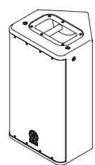
DSR112

natural_image
Isometric line drawing of a rectangular enclosure with a recessed door and mounting holes (no text or symbols)DSR115
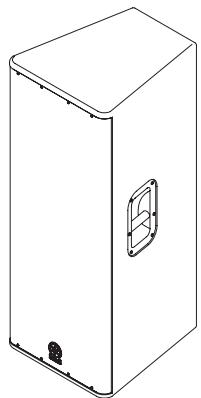
natural_image
Line drawing of a rectangular box with a side panel and mounting base (no text or symbols)DSR215
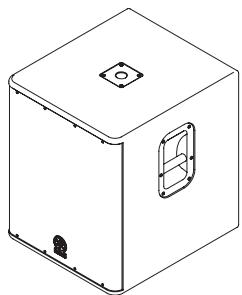
natural_image
Isometric line drawing of a rectangular box with a square top and a side vent, no text or symbols present.DSR118W
■ Speaker processing functionality provided by internal DSP (DSR112/DSR115/DSR215)
The internal DSP delivers high-resolution sound by using speaker processing functionality that has been optimized for each model of the DSR series.
■ FIR-X tuning™ feature (DSR112/DSR115/DSR215)
Linear phase FIR filter provides natural sound quality and smooth frequency response without phase cancellation around the crossover point.
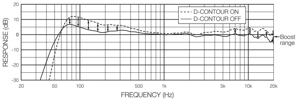
■ D-CONTOUR (Dynamic CONTOUR) feature (DSR112/DSR115/DSR215)
D-CONTOUR is a newly developed three-band multiband compressor. It dynamically adjusts the level of each frequency range according to the volume of speaker outputs. It boosts the high and low frequencies when the volume level is low, and it reduces the amount of boost when the volume level is high. So that it delivers powerful sound tailored to human hearing. For example, this is useful for dance music, etc., if you want to emphasize the rhythm.
■ Light and compact
Featuring class-D amplifier, switching power supply with PFC, and light powerful magnetic neodymium magnet (DSR112 and DSR115 only) provides top-level light and compact body in the class.
■ Powerful protection function
Separate advanced protection circuits in the speaker unit, amplifier unit, and power supply unit ensure optimum reliability and long equipment life.
Included Accessories
- AC power cord
- Owner's manual (this book)
Rear panel
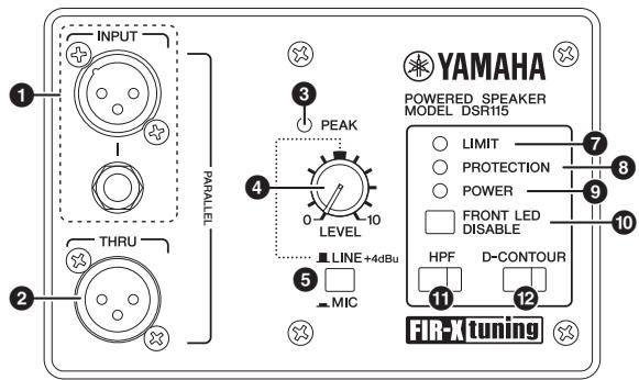
These are balanced XLR and phone input jacks. The DSR118W has XLR jacks (L, R) only.
NOTE
You may use either the XLR or the phone jack, but not both types simultaneously. Please connect to only one of these jacks.
② THRU jack(s)
These are balanced XLR output jack(s). Input signals will be passed through unaffected, since these are parallel connected to the INPUT jacks.
③ PEAK Indicator
Lights red when the input level reaches 3dB below clipping.
If the PEAK indicator frequently lights, adjust the volume of the input source so that the PEAK indicator flashes briefly on the highest input levels.
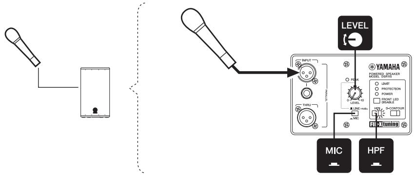
4 LEVEL control
Adjusts the overall output level. Set the MIC/LINE switch (5) of the DSR112, DSR115 and DSR215 to LINE when connecting a device (such as a mixer) whose specified output level is +4dBu. In this condition, set the LEVEL control to roughly a 12:00 position to obtain sufficient output.
5 MIC/LINE switch (DSR112/DSR115/DSR215)
Set this switch to MIC or LINE for INPUT jacks, depending on the level of the input signal. For low-level signals (such as microphones), set the switch to the MIC (■) position. For high-level signals (such as electronic musical instruments and audio equipment), set the switch to the LINE (■) position.
⑥ POLARITY switch (DSR118W)
Selects the subwoofer polarity. You will usually set this switch to NORMAL (■). However, an INVERTED (■) setting may improve low-range response, depending on the type and location of the speaker system. Try both settings and select the one that produces the best low-end sound.
⑦ LIMIT indicator
Lights when the output limiter is active. The output limiter will operate in the following situations, attenuating the output signals to the amplifier.
- If the output voltage of the amplifier has exceeded the maximum value
- If excessive integral power consumption is detected
- If the amplifier overheats
NOTE
- The integral power consumption refers to the sum of power consumption provided to the speaker driver per unit time.
- (DSR112/DSR115/DSR215) If the output voltage of the amplifier has exceeded the maximum value, or if excessive integral power consumption is detected, the LIMIT indicator will light when the amount of attenuation is 3dB or higher.
8 PROTECTION indicator
Lights when the protection system is active. The protection system will operate in the following situations.
NOTE
If the protection system has engaged after the problem was detected, waiting until the amplifier cools down or powering off and on again will return to normal operation. If the unit does not return to normal operation, please contact your Yamaha dealer.
- If amplifier overheating is detected:
The speaker output will be muted.
- If DC output is detected:
After the indicator lights, the speaker output will be muted, and the power supply section will be shut down.
- If overcurrent is detected:
The speaker output will be muted.
- When turning the power on:
Lights for about two seconds when the power supply starts. The indicator turns off when the power supply has started normally.
- When turning the power off:
If the power switch is set to off, or if the power turns off by an unexpected error, the protection system will shut the device down to prevent noise.
9 POWER indicator
Lights when the power switch (14) is set to on.
10 FRONT LED DISABLE switch
Selects turning on or off the LED at the lower left of the unit's front grill. The LED will light when this switch is set to off (■). Turn this switch on (■) when you want to turn off the LED.
NOTE
(DSR112/DSR115/DSR215) When the limiter for protecting the amplifier operates, the LED will light brighter than usual in proportion to the amount of attenuation (6dB or higher).
11 HPF switch (DSR112/DSR115/DSR215)
Toggles the HPF on or off. Press this switch to turn the HPF on (■), and the switch will light. When the switch is turned on, the high-pass filter cuts frequencies below 120Hz. We recommend that you turn this switch on if you connect the speaker directly to a microphone or use the speaker with a subwoofer.
⑫ D-CONTOUR switch (DSR112/DSR115/DSR215)
Toggles the D-CONTOUR (Dynamic CONTOUR) on or off. Press this switch to turn the D-CONTOUR on (■), and the switch will light. Turn this switch on if you want to emphasize the rhythm sound when playing dance music, etc., for example (page 6).
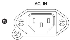
natural_image
Pure electrical circuit lines without any symbolsConnect the supplied AC power cord here. First, connect the power cord to the device, then insert the power cord plug into the AC outlet.
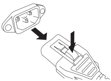
The supplied power cord features a special latching mechanism (V-LOCK) to prevent the power cord from being accidentally disconnected. Connect the power cord by inserting the power cord fully until it is locked.

Be sure to turn the power off before connecting or disconnecting the power cord.
Press the latch button on the plug to disconnect the power cord.
natural_image
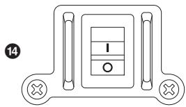
Diagram showing two connected electrical connectors with internal components, one pointing to a switch (no text or symbols present)14 Power switch
Turns the power supply on or off. Move the switch up to the (|) position to turn the power supply on. Move the switch down to the (○) position to turn the power supply off.

Rapidly turning the unit on and off in succession can cause it to malfunction. After turning the unit off, wait for about 5 seconds before turning it on again.
Suspended installation
If you suspend the DSR112 or DSR115, remove the fixing screws at the top (two) and at the lower back (one), and use commercially available M10 long eye bolts each instead. Keep in mind that you will need three long eyes bolts to suspend it. Make sure to use the long eye bolts according to the standards and safety regulations in your area.

- Before doing any installation or construction work, consult with an installation expert.
- When choosing the installation location, suspension wire and mounting hardware, make sure all are strong enough to support the weight of the speaker.
- Some fittings may deteriorate over extended periods of time due to wear and/or corrosion. For optimum safety, the installation should be checked thoroughly at regular intervals.
Yamaha cannot be held responsible for damage or injury caused by insufficient strength of the support structure or improper installation.
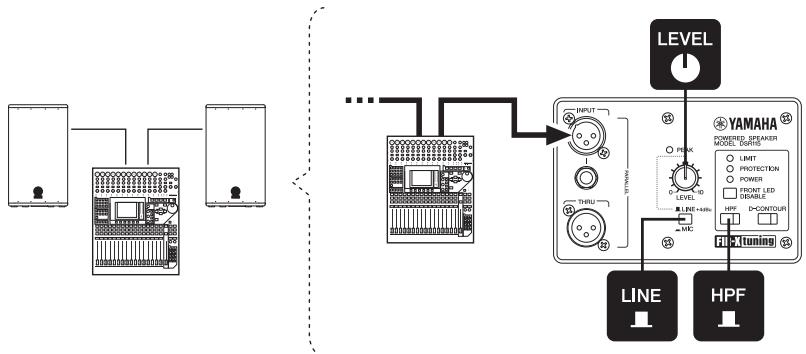
1. Basic SR system
This example illustrates a basic SR system setup using two 2-way speakers. The system is most suitable for a small-sized live space, a restaurant and a practice studio. As necessary, add a stage monitor system illustrated in no. 4.
flowchart
graph TD
    A["Device 1"] --> B["Device 2"]
    B --> C["..."]
    C --> D["Device 3"]
    D --> E["Level"]
    E --> F["YAMAHA"]
    F --> G["LINE"]
    F --> H["HPF"]
    G --> I["Tuning"]
    H --> I
    style A fill:#f9f,stroke:#333
    style B fill:#f9f,stroke:#333
    style D fill:#f9f,stroke:#333
    style E fill:#ccf,stroke:#333
    style F fill:#cfc,stroke:#333
    style G fill:#fcc,stroke:#333
    style H fill:#fcc,stroke:#333
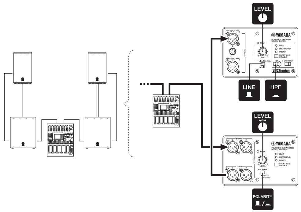
2. SR system with subwoofer
This example illustrates an SR system setup using two 2-way speakers and a subwoofer with speaker poles. The system is most suitable for a small-sized live house, a church and an event site. We recommend that the subwoofer's input LEVEL control is set to a 12:00 position. If you prefer, you can adjust the level as desired. As necessary, add a stage monitor system illustrated in no. 4.
NOTE
Pole sockets for mounting speaker poles are provided at the bottom of the DSR112, DSR115, and at the top of the DSR118W. About the installation, refer to the “Precautions” (page 4).
flowchart
graph TD
    A["Audio System"] --> B["Power Supply Unit"]
    B --> C{Power Supply Unit}
    C --> D["Line 1"]
    C --> E["Line 2"]
    C --> F["Line 3"]
    D --> G["POWER Speaker Control"]
    E --> H["POWER Speaker Control"]
    F --> I["POWER Speaker Control"]
    G --> J["YAMAHA Module"]
    H --> J
    I --> J
    J --> K["LEVEL"]
    J --> L["HPF"]
    J --> M["Polarity"]
    style A fill:#f9f,stroke:#333
    style B fill:#ccf,stroke:#333
    style C fill:#cfc,stroke:#333
    style D fill:#fcc,stroke:#333
    style E fill:#cff,stroke:#333
    style F fill:#ffc,stroke:#333
    style G fill:#fcf,stroke:#333
    style H fill:#fcf,stroke:#333
    style I fill:#fcf,stroke:#333
    style J fill:#cff,stroke:#333
    style K fill:#ffc,stroke:#333
    style L fill:#ffc,stroke:#333
    style M fill:#ffc,stroke:#333
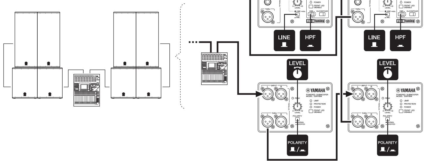
3. Medium-sized SR system
This example illustrates a medium-sized SR system setup using four 2-way speakers and four subwoofers. The system is most suitable for a medium-sized live house, an auditorium and a public hall. As necessary, add a stage monitor system illustrated in no. 4.
NOTE
If you use multiple subwoofers at the same time, set the POLARITY switch of adjacent subwoofers to the same position. Otherwise, the sounds from each speaker may cancel each other, resulting in diminished sound pressure.
flowchart
graph TD
    A["Power Supply Unit 1"] --> B["Grid"]
    C["Power Supply Unit 2"] --> B
    D["Power Supply Unit 3"] --> B
    B --> E["Grid"]
    F["Power Supply Unit 4"] --> G["HPF"]
    G --> H["Line 1"]
    G --> I["HPF"]
    J["Power Supply Unit 5"] --> K["HPF"]
    K --> L["LINE 1"]
    K --> M["HPF"]
    N["Polarity Indicator"] --> O["YAMAHA Power Supply Unit 6"]
    P["Polarity Indicator"] --> Q["YAMAHA Power Supply Unit 7"]
    R["Input Lines"] --> S["Line 1"]
    R --> T["HPF"]
    U["Polarity Indicator"] --> V["Line 1"]
    U --> W["HPF"]
    X["Input Lines"] --> Y["Line 1"]
    X --> Z["HPF"]
    AA["Polarity Indicator"] --> AB["Line 1"]
    AA --> AC["HPF"]
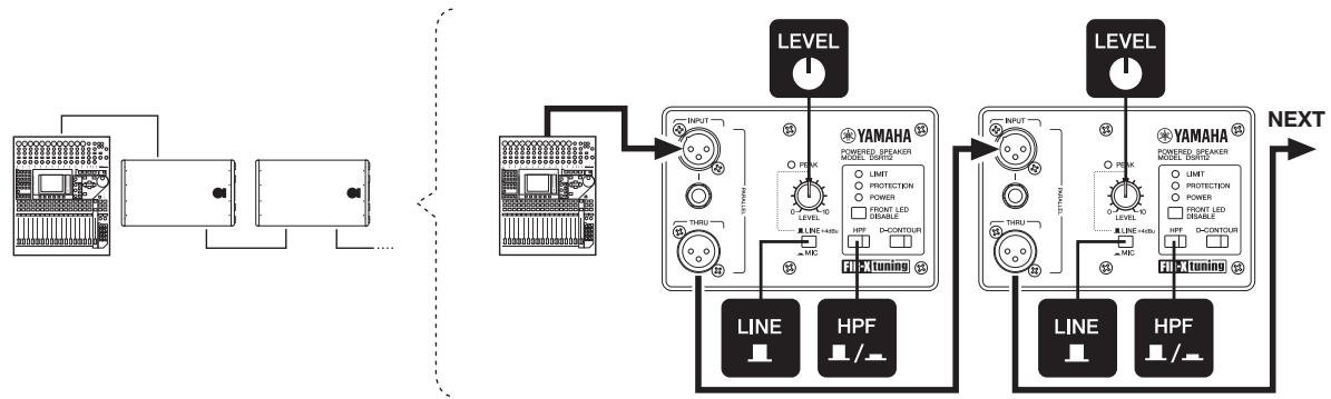
4. Stage monitor system
As necessary, connect speakers in parallel.
NOTE
We recommend that the HPF switch is set to on (■) to reduce feedback when using as a vocal stage monitor.
flowchart
graph TD
    A["Audio System"] --> B["Input"]
    B --> C["THRU"]
    C --> D["LINE"]
    C --> E["HPF"]
    D --> F["PICTuning"]
    E --> F
    F --> G["LEVEL"]
    G --> H["INPUT"]
    H --> I["THRU"]
    H --> J["HPF"]
    I --> K["PICTuning"]
    J --> K
    K --> L["LEVEL"]
    L --> M["INPUT"]
    M --> N["THRU"]
    M --> O["HPF"]
    N --> P["PICTuning"]
    O --> P
    P --> Q["LEVEL"]
    Q --> R["INPUT"]
    R --> S["THRU"]
    R --> T["HPF"]
    S --> U["PICTuning"]
    T --> U
    U --> V["LEVEL"]
    V --> W["INPUT"]
    W --> X["THRU"]
    W --> Y["HPF"]
    X --> Z["PICTuning"]
    Y --> Z
    Z --> AA["LEVEL"]
    AA --> AB["INPUT"]
    AB --> AC["THRU"]
    AB --> AD["HPF"]
    AC --> AE["PICTuning"]
    AD --> AE
    AE --> AF["LEVEL"]
    AF --> AG["INPUT"]
    AG --> AH["THRU"]
    AG --> AI["HPF"]
5. SR system with microphone only (microphone direct input)
This example illustrates an SR system setup using one 2-way speaker connected directly with a microphone. This system can be used in a wide range of places such as corporate events, presentations, and restaurants. Adjust the volume with the LEVEL control to prevent feedback.
Troubleshooting
| Symptom | Possible causes | Possible solution |
| Power does not turn on. | The power cord is not connected properly | Connect the power cord properly. |
| The power cord cannot be disconnected. | You tried to disconnect the power cord without pressing the latch button. | The DSR series feature a V-LOCK power cord. Press the latch button on the plug to disconnect the power cord. |
| Power suddenly went off. | The protection system has operated, shutting down the power supply. | Turn off the power, wait until the amplifier cools down, and then turn on again. |
| No sound. | The cable is not connected properly. | Connect to the INPUT jack properly. |
| Sound is interrupted suddenly. | The protection system has operated, muting the output. | Wait until the amplifier cools down. If the device won't automatically reset itself, turn off the power, and then on again. |
| Sound howls (feedback) | A microphone is directed toward the speaker. | Keep the speaker away from the area where the microphone picks up sound. |
| Sound is amplified too much. | Lower the volume of the input device and locate the microphone more closely to the sound source. | |
| The setting of the HPF switch is not appropriate. | Turn the HPF switch on (■) if you get feedback in low frequency bands. | |
| Each speaker sound differs (if multiple speakers are used) | Settings for each speaker differ. | Set the HPF and D-CONTOUR switches of each speaker to the same positions.Set the POLARITY switch of each speaker to the same position (DSR118W). |
| Sound is distorted | Input volume is excessive. | Lower the volume level of the input device so that the PEAK indicator sometimes lights.If sound continues to be distorted even if you turn down the volume to the minimum, set the MIC/LINE switch to the LINE (■) position (if the switch is set to MIC). |
| Output volume is excessive. | Lower the output level with the LEVEL control so that the LIMIT indicator sometimes lights. | |
| The microphone volume is too low. | The MIC/LINE switch is set to LINE. | Set the MIC/LINE switch to the MIC (■) position. |
| A microphone that needs phantom power is being used. | DSR series products do not provide phantom power.Change your microphone to a dynamic microphone, use a battery, or provide external phantom power. |
*If any specific problem should persist, however, please contact your Yamaha dealer.
Specifications
| General Section | DSR112 | DSR115 | DSR215 | DSR118W | |
| System Type | 12" 2-way, bi-amp powered speaker, bass-reflex type | 15" 2-way, bi-amp powered speaker, bass-reflex type | Dual 15" 2-way, bi-amp powered speaker, bass-reflex type | 18" Powered speaker, bass-reflex type | |
| Frequency Range (-10dB) | 55Hz — 20kHz | 45Hz — 20kHz | 45Hz — 20kHz | 40Hz — 130Hz | |
| Frequency Response (-3dB) | 60Hz — 18kHz | 55Hz — 18kHz | 55Hz — 18kHz | 50Hz — 110Hz | |
| Coverage Angle | H90° × V60° | - | |||
| Crossover Type | FIR-X tuningTM (linear phase FIR filter) | - | |||
| Crossover Frequency | 1.7kHz | 1.7kHz | 1.7kHz | - | |
| Measured Maximum SPL (peak) IEC noise @ 1m | 134dB SPL | 136dB SPL | 138dB SPL | 132dB SPL | |
| Amplifier Section | |||||
| Amplifier Type | Class-D | ||||
| Power Rating *1 | 1300W | 800W | |||
| Low-Frequency | 850W | 800W | |||
| High-Frequency | 450W | - | |||
| Cooling | Natural Convection | ||||
| Controls | LEVEL control, MIC/LINE switch, HPF switch, D-CONTOUR switch, FRONT LED DISABLE switch, POWER switch | LEVEL control, POLARITY switch, FRONT LED DISABLE switch, POWER switch | |||
| Indicators | PEAK (red), LIMIT (red), PROTECTION (red), POWER (green), Front (white), HPF (orange), D-CONTOUR (orange) | PEAK (red), LIMIT (red), PROTECTION (red), POWER (green), Front (white) | |||
| HPF Frequency | 120Hz(-6dB) 24dB/oct | - | |||
| Boost Type | D-CONTOUR (Dynamic CONTOUR) | - | |||
| Protection | Load | POWER switch on/off: Mute | |||
| DC-fault: power supply shuts down automatically (reset manually) | |||||
| Integral Power Protection: Limit the output (return automatically) | |||||
| Clip limiting | |||||
| Amplifier | Thermal: Limit the output or Mute (return automatically) | Thermal: Mute (return automatically) | |||
| Output through current: Amplifier shuts down automatically (reset manually) | |||||
| Power supply | Thermal : Amplifier shuts down automatically (reset manually) | ||||
| Over voltage: Power supply shuts down automatically (reset manually) | |||||
| Connectors | Input | XLR-3-31 x1 (Balanced) TRS Phone Jack x1 (Balanced) | XLR-3-31 x2 (Balanced) | ||
| Output | XLR-3-32 x1 (Balanced) Parallel connection with INPUT | XLR-3-32 x2 (Balanced) Parallel connection with INPUT | |||
| Power | AC inlet x1 | ||||
| Power Consumption | 1/8 Power | 100W | 140W | 100W | |
| Transducer Section | DSR112 | DSR115 | DSR215 | DSR118W | |
| Low-Frequency | 12" cone | 15" cone | 2 x 15" cone | 18" cone | |
| Magnet | Materials | Neodymium Magnet | Neodymium Magnet | Ferrite Magnet | Ferrite Magnet |
| Voice Coil | Diameter | 3" | 3" | 2.5" | 3" |
| High-Frequency | 2" Titanium diaphragm compression driver | - | |||
| Magnet | Materials | Neodymium Magnet | - | ||
| Enclosure | |||||
| Material | LINE-X® coated wood | ||||
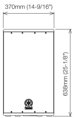
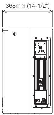
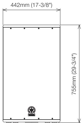
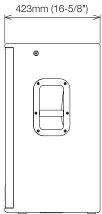
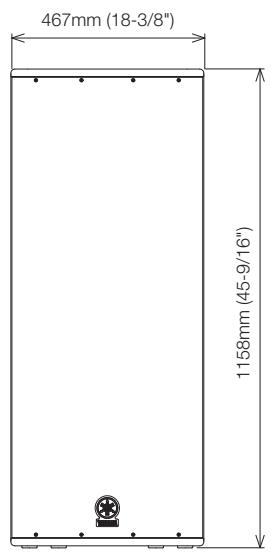
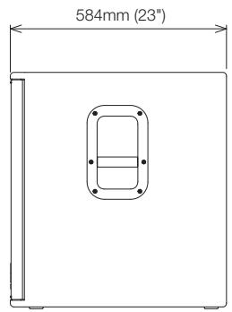
| Dimensions (W x H x D) | 370 x 638 x 368 mm(14-9/16" x 25-1/8" x 14-1/2") | 442 x 755 x 423 mm(17-3/8" x 29-3/4" x 16-5/8") | 467 x 1158 x 520 mm(18-3/8" x 45-9/16" x 20-1/2") | 520 x 638 x 584 mm(20-1/2" x 25-1/8" x 23") | |
| Weight | 21.2 kg (46 lbs) | 28.0 kg (61 lbs) | 49.8 kg (109 lbs) | 42.0 kg (92 lbs) | |
| Externals Finish, Color | LINE-X®, Black | ||||
| Grille | 16 gauge matte black powder coated perforated steel grille | ||||
| Metal Handle | 1pc (Top Board) | 2pcs (Side Board) | |||
| Pole Socket | Diameter | 35mm (Bottom Board) | - | 35mm (Top Board) | |
| Flying Hardware | 3 x M10 (Top L/R 1pc each, Bottom rear 1pc) | - | - | ||
Input Characteristics
| MIC/LINE switch: LINE | DSR112 | DSR115 | DSR215 | DSR118W | |
| Input Sensitivity | LEVEL position: maximum | 0dBu | |||
| LEVEL position: center (12 o'clock) | +7dBu | - | |||
| Maximum Input Level | +24dBu | ||||
| Input Impedance | 12kΩ | 10kΩ | |||
| MIC/LINE switch: MIC | |||||
| Input Sensitivity | LEVEL position: maximum | -25dBu | - | ||
| Maximum Input Level | -11dBu | - | |||
| Input Impedance | 8kΩ | - | |||
0dBu is referenced to 0.775Vrms.
*1. THD+N=10% at minimum impedance
D-CONTOUR Frequency Response Chart
line
| FREQUENCY (Hz) | D-CONTOUR ON (Response dB) | D-CONTOUR OFF (Response dB) | | -------------- | -------------------------- | --------------------------- | | 20 | -30 | -30 | | 50 | -10 | -10 | | 100 | 10 | 10 | | 500 | 0 | 0 | | 1k | 0 | 0 | | 5k | 0 | 0 | | 10k | 0 | 0 | | 20k | 0 | 0 |Dimensions
DSR112
DSR115
natural_image
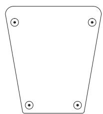
Pure technical diagram of a mechanical component with four mounting holes and a central circular feature (no text or symbols)DSR215
natural_image
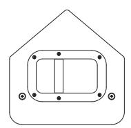
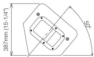
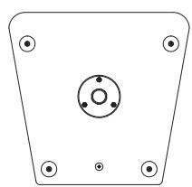
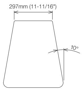
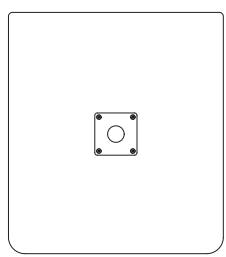
Simple geometric shape with four corner dots, no text or symbols presentDSR118W
natural_image
Simple geometric diagram with a square and central circle, no text or symbols present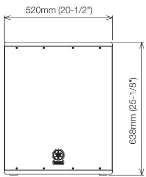
Block Diagram
DSR112/DSR115/DSR215
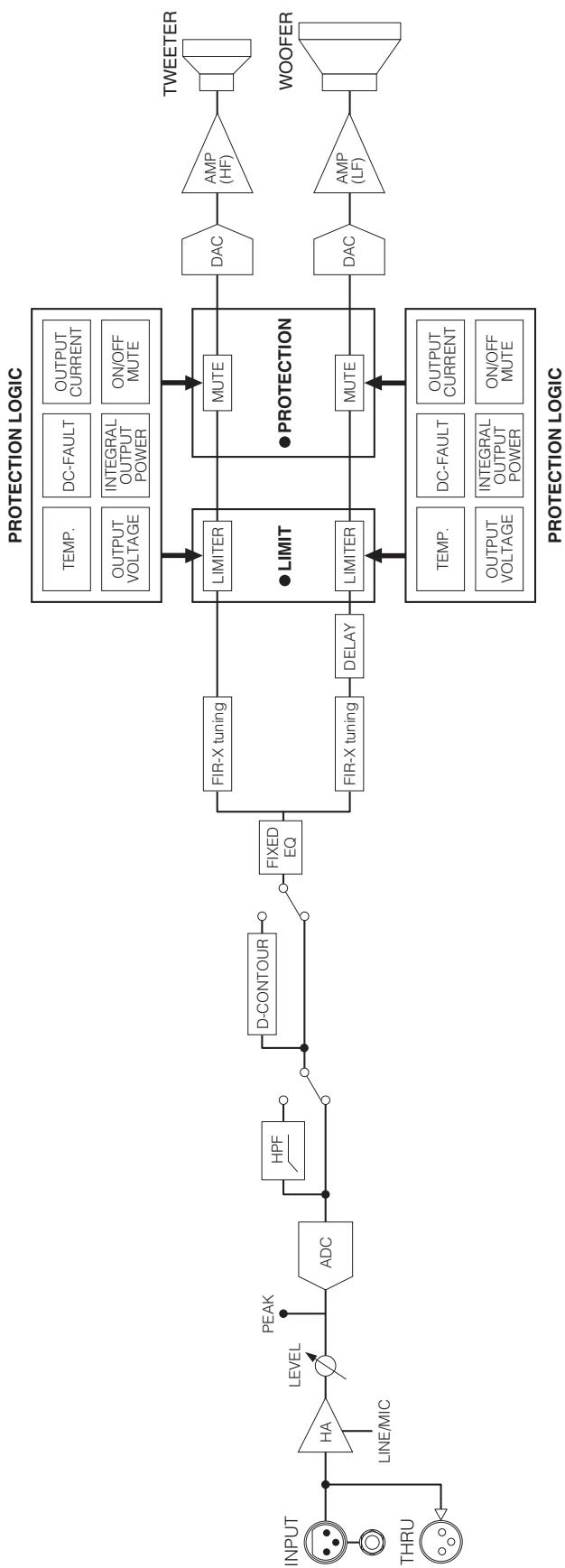
flowchart
graph LR
    INPUT["INPUT"] --> HA["HA"]
    THRU["THRU"] --> HA
    HA --> LEVEL["LEVEL"]
    LEVEL --> PEAK["PEAK"]
    PEAK --> ADC["ADC"]
    ADC --> HPF["HPF"]
    HPF --> D-CONTOUR["D-CONTOUR"]
    D-CONTOUR --> FIXEDEQ["FIXED EQ"]
    FIXEDEQ --> FIRX_Tuning["FIR-X tuning"]
    FIXEDEQ --> FIRX_Tuning2_DELAY["FIR-X tuning"]
    FIRX_Tuning --> LIMITER["LIMITER"]
    FIRX_Tuning2 DELAY --> LIMITER2 DELAY
    LIMITER --> MUTE1["MUTE"]
    LIMITER2 DELAY --> MUTE2["MUTE"]

    PROTECTION_LOGIC["PROTECTION LOGIC"] --> TEMP["TEMP."]
    PROTECTION_LOGIC --> DC_FAULT["DC-FAULT"]
    PROTECTION_LOGIC --> OUTPUT_CURRENT["OUTPUT CURRENT"]
    PROTECTION_LOGIC --> OUTPUT_VOLTAGE["OUTPUT VOLTAGE"]
    PROTECTION_LOGIC --> INTEGRAL_OUTPUT_POWER["INTEGRAL OUTPUT POWER"]
    PROTECTION_LOGIC --> ON/OFF_MUTE["ON/OFF MUTE"]

    TWEETER["TWEETER"] --> AMP_HF["AMP (HF)"]
    WOOFER["WOOFER"] --> AMP_LF["AMP (LF)"]

    style TALENDRAVE fill:#f9f9f9,stroke:#333
DSR118W
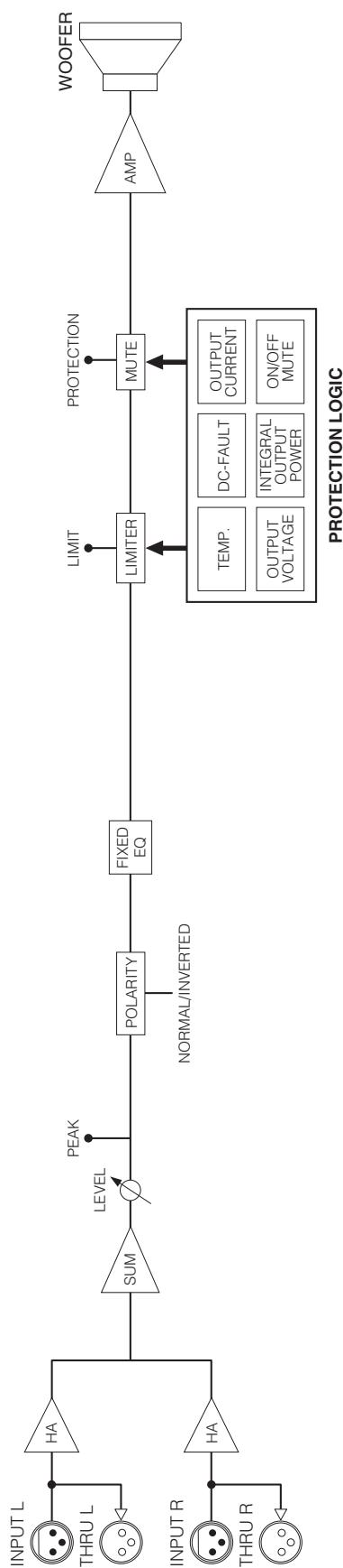
flowchart
graph LR
    A["INPUT L"] --> B["HA"]
    C["THRU L"] --> D["HA"]
    E["INPUT R"] --> F["HA"]
    G["THRU R"] --> H["HA"]
    B --> I["SUM"]
    D --> J["LEVEL"]
    F --> K["POLARITY"]
    H --> L["NORMAL/INVERTED"]
    I --> M["FIXE EQ"]
    J --> M
    K --> M
    L --> M
    M --> N["LIMITER"]
    N --> O["PROTECTION"]
    O --> P["AMP"]
    P --> Q["WOOFER"]
    R["TEMP."] --> N
    S["DC-FAULT"] --> N
    T["OUTPUT CURRENT"] --> N
    U["OUTPUT VOLTAGE"] --> N
    V["INTEGRAL OUTPUT POWER"] --> N
    W["ON/OFF MUTE"] --> N
    X["PEAK"] --> I

YAMAHA
Yamaha Pro Audio global website
http://www.yamahaproaudio.com/
Yamaha Manual Library
© 2010 Yamaha Corporation
006MWAP3.3-01A0
Printed in Vietnam
WU43450