
DM2000V22ADD - Digital Mixer YAMAHA - Free user manual and instructions
Find the device manual for free DM2000V22ADD YAMAHA in PDF.
| Product Type | Digital Mixing Console |
| Brand | YAMAHA |
| Model | DM2000V22ADD |
| Dimensions (W x D x H) | 1220 mm x 760 mm x 340 mm |
| Weight | 60 kg |
| Power Supply | 100-240 V AC, 50/60 Hz, 300 W |
| Input Channels | 96 (48 mono + 48 stereo) |
| Output Buses | 8 buses, 12 aux, 4 matrix, stereo, surround 6.1 |
| Display | Color Touch LCD Screen |
| Built-in Effects | Internal effect processors + Add-On packages |
| Connectivity | Slots for MY cards, analog and digital inputs/outputs |
| Surround | Surround monitoring with matrices, bass management (THX) |
| Software Update | Version 2.20 (latest) |
| Main Functions | Multichannel digital mixing, automation, scenes, GPI, monitoring |
| Maintenance and Cleaning | Clean with a soft dry cloth, avoid solvents |
| Safety | Grounding, do not expose to moisture, unplug before maintenance |
| Spare Parts and Reparability | Contact an authorized Yamaha service center for repairs |
| General Information | Professional console for studio and sound reinforcement |
Frequently Asked Questions - DM2000V22ADD YAMAHA
User questions about DM2000V22ADD YAMAHA
0 question about this device. Answer the ones you know or ask your own.
Ask a new question about this device
Download the instructions for your Digital Mixer in PDF format for free! Find your manual DM2000V22ADD - YAMAHA and take your electronic device back in hand. On this page are published all the documents necessary for the use of your device. DM2000V22ADD by YAMAHA.
USER MANUAL DM2000V22ADD YAMAHA
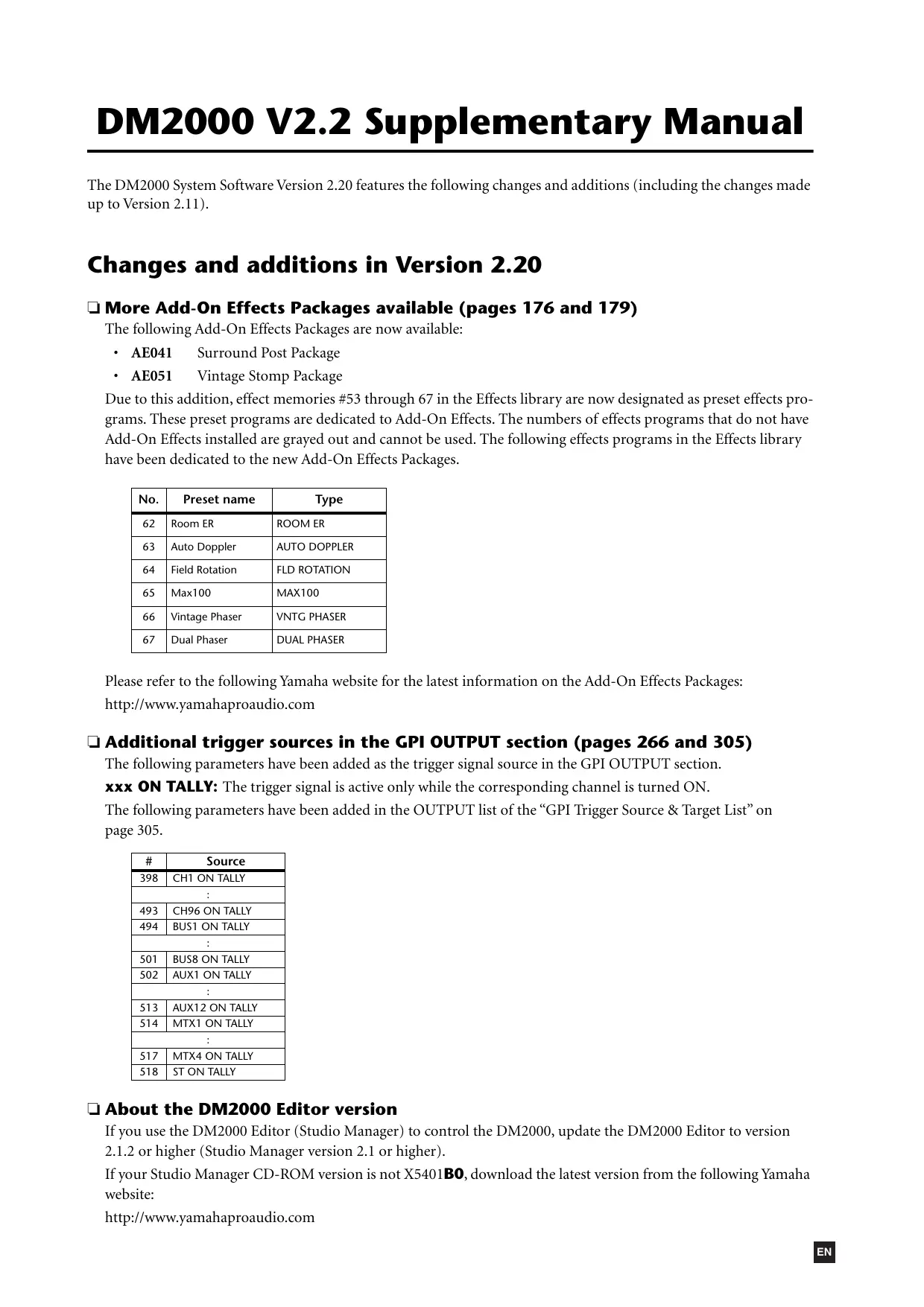
The DM2000 System Software Version 2.20 features the following changes and additions (including the changes made up to Version 2.11).
Changes and additions in Version 2.20
More Add-On Effects Packages available (pages 176 and 179)
The following Add-On Effects Packages are now available:
- AE041 Surround Post Package
- AE051 Vintage Stomp Package
Due to this addition, effect memories #53 through 67 in the Effects library are now designated as preset effects programs. These preset programs are dedicated to Add-On Effects. The numbers of effects programs that do not have Add-On Effects installed are grayed out and cannot be used. The following effects programs in the Effects library have been dedicated to the new Add-On Effects Packages.
| No. | Preset name | Type |
| 62 | Room ER | ROOM ER |
| 63 | Auto Doppler | AUTO DOPPLER |
| 64 | Field Rotation | FLD ROTATION |
| 65 | Max100 | MAX100 |
| 66 | Vintage Phaser | VNTG PHASER |
| 67 | Dual Phaser | DUAL PHASER |
Please refer to the following Yamaha website for the latest information on the Add-On Effects Packages: http://www.yamahaaproaudio.com
Additional trigger sources in the GPI OUTPUT section (pages 266 and 305)
The following parameters have been added as the trigger signal source in the GPI OUTPUT section.
xxx ON TALLY: The trigger signal is active only while the corresponding channel is turned ON.
The following parameters have been added in the OUTPUT list of the "GPI Trigger Source & Target List" on page 305.
| # | Source |
| 398 | CH1 ON TALLY |
| : | |
| 493 | CH96 ON TALLY |
| 494 | BUS1 ON TALLY |
| : | |
| 501 | BUS8 ON TALLY |
| 502 | AUX1 ON TALLY |
| : | |
| 513 | AUX12 ON TALLY |
| 514 | MTX1 ON TALLY |
| : | |
| 517 | MTX4 ON TALLY |
| 518 | ST ON TALLY |
About the DM2000 Editor version
If you use the DM2000 Editor (Studio Manager) to control the DM2000, update the DM2000 Editor to version 2.1.2 or higher (Studio Manager version 2.1 or higher).
If your Studio Manager CD-ROM version is not X5401B0, download the latest version from the following Yamaha website:
http://www.yamahaproaudio.com
Changes in V2.11
Y96K card and MY16-mLAN card support (pages 70 and 349)
The Waves Y96K Plug-in DSP card (supported by Version 2.10) and the MY16-mLAN interface card are now supported. Also, in accordance with the mLAN MIDI specifications, multiple MIDI ports on SLOT 1 have been changed to a single port. (Now you do not need to select Ports 1-8.)
Please refer to the following website for the latest information on compatible cards, and on the number of cards that can be installed in combination with other cards.
http://www.yamahaproudio.com
Changes in V2.10
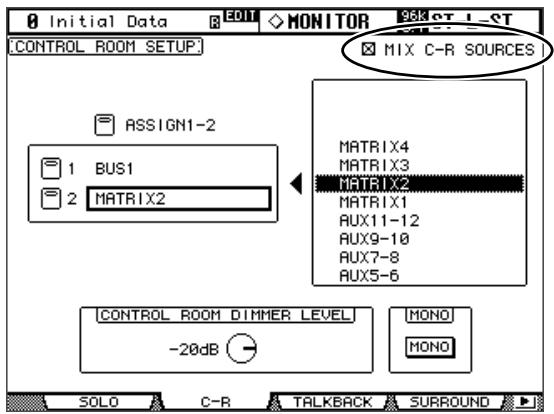
MIX C-R SOURCES parameter added to Control Room Monitor (page 159)
A "MIX C-R SOURCES" parameter has been added in the CONTROL ROOM SETUP page. In V2.0, you could choose one item from 2TR D1, D2, D3, A1, or A2 as a monitor source, plus other sources (STEREO, ASSIGN1, or ASSIGN2). In V2.1, you can turn the MIX C-R SOURCES parameter off to disable this simultaneous selection.
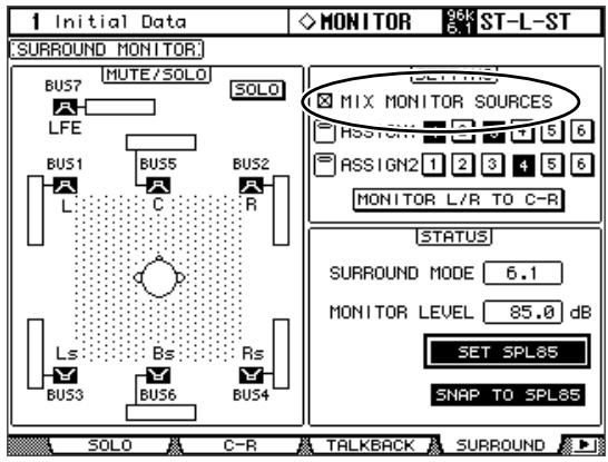
MIX MONITOR SOURCES parameter added to Surround Monitor (page 160)
A "MIX MONITOR SOURCES" parameter has been added to the SURROUND MONITOR page. In V2.0, you could choose ASSIGN1 or ASSIGN2 in addition to a BUS as the monitor source, but in V2.1 you can turn this parameter off to disable this simultaneous selection.
THX preset added to Surround Monitor (page 161-163)
Presents for the THX pm3 monitor system have been added to the bass management settings for surround monitoring. Several supplements have also been added regarding the surround monitor settings, so please replace the corresponding pages with the following.
Configuring Surround Monitoring
Surround monitoring, including speaker setup, monitor matrix, Bass Management, and monitor alignment, is configured on the Surround Monitor Setup page.
1 Use the MONITOR [DISPLAY] button to locate the Surround Monitor Setup page.

2 Use the cursor buttons to select the parameters, and use the Parameter wheel, INC/DEC buttons, and [ENTER] button to set them.
SPEAKER SETUP: These parameters are for setting the volume balance of the surround monitor speakers. Select the OSC (Oscillator) parameter and choose from PINK NOISE, 500-2K (pink noise through a 500Hz to 2kHz BPF), 1K (1 kHz sinewave), or 50Hz (50 Hz sinewave). Use the ON/OFF button to turn the Oscillator on and off. When on, the Oscillator outputs a signal at -20 dB to the Surround Channels whose icons are highlighted. You can turn on and off Oscillator output for speakers individually. Speaker icons can be selected by using the cursor buttons. The signal phase of the LFE Channel can be reversed by using the SW phase button. When ROTATE is on, the Oscillator signal is output by each speaker in turn in a clockwise direction (3 second signal, 2 second pause). SURR. MODE: This indicates the currently selected Surround mode, which is set on the Surround Mode page (see page 97).
Note: If you had been monitoring with the surround mode set to 6.1 and the monitor matrix mode set to 6.1 on DM2000 units with system software earlier than V2.1, the playback may not always be correct on V2.1.
MONITOR MATRIX: This is used to select the Surround Monitor Matrix. In 6.1 Surround mode, you can select 6.1, 5.1, 3-1, or ST. In 5.1 Surround mode, you can select 5.1, 3-1, or ST. In 3-1 Surround mode, you can select 3-1 or ST.
When a down mix Monitor Matrix is selected, you can attenuate signals by using the ATT parameters. You can use the Surround Monitor settings in Stereo mode, but Monitor Matrix is fixed to ST.
Note: If you choose monitor matrix mode = 3-1, you must set the following three attenuation amounts to the same value.
ATT1 for surround mode 3-1
- ATT4 for surround mode 5.1
ATT5 for surround mode 6.1
These ATT values are not attenuators for down-mixing; rather, they are used as monitor adjustment attenuators for lowering the playback volume of the Ls, Rs, Ls2, and Rs2 speakers.
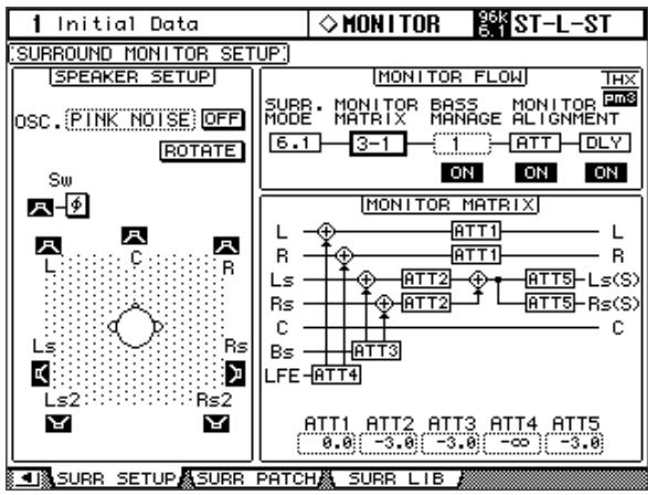
BASS MANAGEMENT
You can set the filter and attenuator settings for each Surround Monitor Channel using eight preset Bass Management modes. The following presets are available:
| Presets | Parameters | |||||
| No. | Title | HPF 1, 2, 3 | LPF1 | LPF2 | ATT 1 & 2 | AMP |
| 1 | DVD LFE80Hz | 80-12 | 80-24 | 80-24 | 0 | 10 |
| 2 | DVD LFE120Hz | 80-12 | 120-42 | 80-24 | 0 | 10 |
| 3 | Movie LFE80Hz | 80-12 | 80-24 | 80-24 | -3 | 10 |
| 4 | Movie LFE120Hz | 80-12 | 120-42 | 80-24 | -3 | 10 |
| 5 | Bypass | THRU | THRU | MUTE | 0 | 0 |
| THXD | THX DVD | 80-12 | 120-42 | 80-24L | 0 | 10 |
| THXF | THX Movie | 80-12 | 120-42 | 80-24L | -3 | 10 |
| THXM | THX Music | 80-12 | 120-42 | 80-24L | 0 | 10 |
ATT1: Adjusts the level difference between LR and LsRs.
ATT2: Adjusts the level difference between C and Bs.
AMP: Corrects the LFE channel level.
HPF1-3: Cut the low range so that the speakers' supporting frequency ranges will not interfere with the subwoofer signals.
HPF1-2: Cut the high range so that the subwoofer's supporting frequency ranges will not interfere with other speakers' signals.
Note:
- If you select preset THXD or THXF, you cannot change the parameters.
- If you select preset THXM, you can switch AMP between 10 dB and 0 dB. However, you cannot change other parameters.
You can set the Bass Management parameters in the following ranges:
| Parameters | Range |
| HPF 1, 2, 3 | THRU, 80-12, 80-12L, 80-24, 80-24L |
| LPF1 | THRU, 80-24, 80-24L, 120-42 |
| LPF2 | THRU, 80-24, 80-24L, MUTE |
| ATT 1 & 2 | 0 to -12 dB (1 dB steps) |
| AMP | 0 to +12 dB (1 dB steps) |
The HPF 1, 2, 3, and LPF 1 & 2 values indicate a cut-off frequency and a filter response. For example, "80-12" means a cutoff frequency of 80Hz and a filter response of -12dB /octave.
"L" means Linkwitz filter. Other filters are Butterworth.
- Changes and additions in Version 2.20
- More Add-On Effects Packages available (pages 176 and 179)
- Additional trigger sources in the GPI OUTPUT section (pages 266 and 305)
- About the DM2000 Editor version
- Changes in V2.11
- Y96K card and MY16-mLAN card support (pages 70 and 349)
- Changes in V2.10
- MIX C-R SOURCES parameter added to Control Room Monitor (page 159)
- MIX MONITOR SOURCES parameter added to Surround Monitor (page 160)
- THX preset added to Surround Monitor (page 161-163)
- Configuring Surround Monitoring
- BASS MANAGEMENT
- Note:
Brand : YAMAHA
Model : DM2000V22ADD
Category : Digital Mixer