
PM5D-RH - Digital Mixer YAMAHA - Free user manual and instructions
Find the device manual for free PM5D-RH YAMAHA in PDF.
User questions about PM5D-RH YAMAHA
0 question about this device. Answer the ones you know or ask your own.
Ask a new question about this device
Download the instructions for your Digital Mixer in PDF format for free! Find your manual PM5D-RH - YAMAHA and take your electronic device back in hand. On this page are published all the documents necessary for the use of your device. PM5D-RH by YAMAHA.
USER MANUAL PM5D-RH YAMAHA
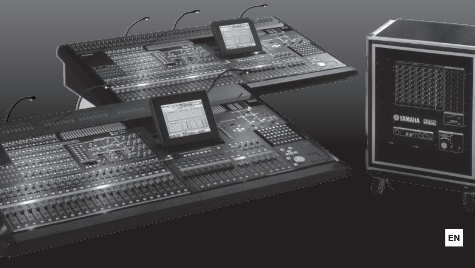
DIGITAL MIXING CONSOLE
DSP5D
DIGITAL MIXING SYSTEM
PM5D/PM5D-RH V2
DSP5D
Owner's Manual
FCC INFORMATION (U.S.A.)
1. IMPORTANT NOTICE: DO NOT MODIFY THIS UNIT!
This product, when installed as indicated in the instructions contained in this manual, meets FCC requirements. Modifications not expressly approved by Yamaha may void your authority, granted by the FCC, to use the product.
- IMPORTANT: When connecting this product to accessories and/ or another product use only high quality shielded cables. Cable/s supplied with this product MUST be used. Follow all installation instructions. Failure to follow instructions could void your FCC authorization to use this product in the USA.
- NOTE: This product has been tested and found to comply with the requirements listed in FCC Regulations, Part 15 for Class "B" digital devices. Compliance with these requirements provides a reasonable level of assurance that your use of this product in a residential environment will not result in harmful interference with other electronic devices. This equipment generates/uses radio frequencies and, if not installed and used according to the instructions found in the users manual, may cause interference harmful to the operation of other electronic devices. Compliance with FCC regulations does
not guarantee that interference will not occur in all installations. If this product is found to be the source of interference, which can be determined by turning the unit "OFF" and "ON", please try to eliminate the problem by using one of the following measures:
Relocate either this product or the device that is being affected by the interference.
Utilize power outlets that are on different branch (circuit breaker or fuse) circuits or install AC line filter/s.
In the case of radio or TV interference, relocate/reorient the antenna. If the antenna lead-in is 300 ohm ribbon lead, change the lead-in to co-axial type cable.
If these corrective measures do not produce satisfactory results, please contact the local retailer authorized to distribute this type of product. If you can not locate the appropriate retailer, please contact Yamaha Corporation of America, Electronic Service Division, 6600 Orangethorpe Ave, Buena Park, CA90620
The above statements apply ONLY to those products distributed by Yamaha Corporation of America or its subsidiaries.
- This applies only to products distributed by YAMAHA CORPORATION OF AMERICA.
(class B)

The above warning is located on the rear/top of the unit.
Explanation of Graphical Symbols
The lightning flash with arrowhead symbol within an equilateral triangle is intended to alert the user to the presence of uninsulated "dangerous voltage" within the product's enclosure that may be of sufficient magnitude to constitute a risk of electric shock to persons.

The exclamation point within an equilateral triangle is intended to alert the user to the presence of important operating and maintenance (servicing) instructions in the literature accompanying the product.
IMPORTANT SAFETY INSTRUCTIONS
1 Read these instructions.
2 Keep these instructions.
3 Heed all warnings.
4 Follow all instructions.
5 Do not use this apparatus near water.
6 Clean only with dry cloth.
7 Do not block any ventilation openings. Install in accordance with the manufacturer's instructions.
8 Do not install near any heat sources such as radiators, heat registers, stoves, or other apparatus (including amplifiers) that produce heat.
9 Do not defeat the safety purpose of the polarized or grounding-type plug. A polarized plug has two blades with one wider than the other. A grounding type plug has two blades and a third grounding prong. The wide blade or the third prong are provided for your safety. If the provided plug does not fit into your outlet, consult an electrician for replacement of the obsolete outlet.
10 Protect the power cord from being walked on or pinched particularly at plugs, convenience receptacles, and the point where they exit from the apparatus.
11 Only use attachments/accessories specified by the manufacturer.
12 Use only with the cart, stand, tripod, bracket, or table specified by the manufacturer, or sold with the apparatus. When a cart is used, use caution when moving the cart/apparatus combination to avoid injury from tip-over.
13 Unplug this apparatus during lightning storms or when unused for long periods of time.
14 Refer all servicing to qualified service personnel. Servicing is required when the apparatus has been damaged in any way, such as power-supply cord or plug is damaged, liquid has been spilled or objects have fallen into the apparatus, the apparatus has been exposed to rain or moisture, does not operate normally, or has been dropped.
This product contains a high intensity lamp that contains a small amount of mercury. Disposal of this material may be regulated due to environmental considerations. For disposal information in the United States, refer to the Electronic Industries Alliance web site: www.eiae.org
- This applies only to the PM5D (PM5D-RH) distributed by YAMAHA CORPORATION OF AMERICA.
(mercury)
IMPORTANT NOTICE FOR THE UNITED KINGDOM
Connecting the Plug and Cord
WARNING: THIS APPARATUS MUST BE EARTHED IMPORTANT. The wires in this mains lead are coloured in accordance with the following code:
GREEN- AND- YELLOW : EARTH
BLUE : NEUTRAL
BROWN : LIVE
As the colours of the wires in the mains lead of this apparatus may not correspond with the coloured markings identifying the terminals in your plug proceed as follows:
The wire which is coloured GREEN-and-YELLOW must be connected to the terminal in the plug which is marked by the letter E or by the safety earth symbol or colored GREEN or GREEN-and-YELLOW.
The wire which is coloured BLUE must be connected to the terminal which is marked with the letter N or coloured BLACK.
The wire which is coloured BROWN must be connected to the terminal which is marked with the letter L or coloured RED.
This applies only to the DSP5D distributed by
Yamaha-Kemble Music (U.K.) Ltd.
(3 wires)
COMPLIANCE INFORMATION STATEMENT (DECLARATION OF CONFORMITY PROCEDURE)
Responsible Party : Yamaha Corporation of America
Address: 6600 Orangethorpe Ave., Buena Park, Calif.
90620
Telephone:714-522-9011
Type of Equipment : Digital Mixing System
Model Name:DSP5D
This device complies with Part 15 of the FCC Rules.
Operation is subject to the following two conditions:
1) this device may not cause harmful interference, and
2) this device must accept any interference received including interference that may cause undesired operation.
See user manual instructions if interference to radio reception is suspected.
- This applies only to products distributed by
YAMAHA CORPORATION OF AMERICA.
(FCC DoC)
ADVARSEL!
COMPLIANCE INFORMATION STATEMENT (DECLARATION OF CONFORMITY PROCEDURE)
Responsible Party : Yamaha Corporation of America
Address: 6600 Orangethorpe Ave., Buena Park, Calif.
90620
Telephone:714-522-9011
Type of Equipment : Digital Mixing Console
Model Name:PM5D/PM5D-RH
This device complies with Part 15 of the FCC Rules.
Operation is subject to the following two conditions:
1) this device may not cause harmful interference, and
2) this device must accept any interference received including interference that may cause undesired operation.
See user manual instructions if interference to radio reception is suspected.
This applies only to products distributed by
YAMAHA CORPORATION OF AMERICA.
(FCC DoC)
This product contains a battery that contains perchlorate material.
Perchlorate Material—special handling may apply,
See www.dtsc.ca.gov/hazardouswaste/perchlorate.
- This applies only to products distributed by YAMAHA CORPORATION OF AMERICA.
(Perchlorate)
PRECAUTIONS
PLEASE READ CAREFULLY BEFORE PROCEEDING
- Please keep this manual in a safe place for future reference.

WARNING
Always follow the basic precautions listed below to avoid the possibility of serious injury or even death from electrical shock, short-circuiting, damages, fire or other hazards. These precautions include, but are not limited to, the following:
Power supply/Power cord
- Only use the voltage specified as correct for the device. The required voltage is printed on the name plate of the device.
- Use only the specified power supply (PW800W or an equivalent recommended by Yamaha).
- (DSP5D only) Use only the included power cord.
If you intend to use the device in an area other than in the one you purchased, the included power cord may not be compatible. Please check with your Yamaha dealer. - Do not place the power cord near heat sources such as heaters or radiators, and do not excessively bend or otherwise damage the cord, place heavy objects on it, or place it in a position where anyone could walk on, trip over, or roll anything over it.
- (DSP5D only) Be sure to connect to an appropriate outlet with a protective grounding connection. Improper grounding can result in electrical shock.
Do not open
- Do not open the device or attempt to disassemble the internal parts or modify them in any way. The device contains no user-serviceable parts. If it should appear to be malfunctioning, discontinue use immediately and have it inspected by qualified Yamaha service personnel.
Water warning
- Do not expose the device to rain, use it near water or in damp or wet conditions, or place containers on it containing liquids which might spill into any openings. If any liquid such as water seeps into the device, turn off the power immediately and unplug the power cord from the AC outlet. Then have the device inspected by qualified Yamaha service personnel.
- Never insert or remove an electric plug with wet hands.
If you notice any abnormality
- If the power cord or plug becomes frayed or damaged, or if there is a sudden loss of sound during use of the device, or if any unusual smells or smoke should appear to be caused by it, immediately turn off the power switch, disconnect the electric plug from the outlet, and have the device inspected by qualified Yamaha service personnel.
- If this device or power supply should be dropped or damaged, immediately turn off the power switch, disconnect the electric plug from the outlet, and have the device inspected by qualified Yamaha service personnel.

CAUTION
Always follow the basic precautions listed below to avoid the possibility of physical injury to you or others, or damage to the device or other property. These precautions include, but are not limited to, the following:
Power supply/Power cord
- Remove the electric plug from the outlet when the device is not to be used for extended periods of time, or during electrical storms.
- When removing the electric plug from the device or an outlet, always hold the plug itself and not the cord. Pulling by the cord can damage it.
- Turn the PM5D ON/OFF using only the power supply PW800W POWER switch. Turning the PM5D ON/OFF by plugging or unplugging the power cord, using a switch on a power tap, a breaker switch, or similar external means can result in damage.
Location
- When transporting or moving the device, always use four or more people (PM5D), two or more people (DSP5D). Attempting to lift the device by yourself may damage your back, result in other injury, or cause damage to the device itself.
-
Before moving the device, remove all connected cables.
-
When setting up the DSP5D, make sure that the AC outlet you are using is easily accessible. If some trouble or malfunction occurs, immediately turn off the power switch and disconnect the plug from the outlet. Even when the power switch is turned off, electricity is still flowing to the product at the minimum level. When you are not using the product for a long time, make sure to unplug the power cord from the wall AC outlet.
- If the DSP5D is to be mounted in an EIA-standard rack, leave the back of the rack open and make sure that it is at least 10cm away from walls or surfaces. Also, if the DSP5D is to be mounted with devices that tend to generate heat, such as power amplifiers, be sure to keep an adequate gap between the DSP5D and the heat-generating devices or install ventilation panels to prevent high temperatures from developing inside the DSP5D. Inadequate ventilation can result in overheating, possibly causing damage to the device(s), or even fire.
-
Do not use the DSP5D in a confined, poorly-ventilated location. If the DSP5D is to be used in a small space other than an EIA-standard rack, make sure that there is adequate space between the device and surrounding walls or other devices: at least 10cm behind and 10cm above. Inadequate ventilation can result in overheating, possibly causing damage to the device(s), or even fire.
-
Avoid setting all equalizer controls and faders to their maximum. Depending on the condition of the connected devices, doing so may cause feedback and may damage the speakers.
- Do not expose the device to excessive dust or vibrations, or extreme cold or heat (such as in direct sunlight, near a heater, or in a car during the day) to prevent the possibility of panel disfiguration or damage to the internal components.
- Do not place the device in an unstable position where it might accidentally fall over.
- Do not block the vents. This device has ventilation holes at the front and rear to prevent the internal temperature from becoming too high. In particular, do not place the device on its side or upside down. Inadequate ventilation can result in overheating, possibly causing damage to the device(s), or even fire.
- Do not use the device in the vicinity of a TV, radio, stereo equipment, mobile phone, or other electric devices. Doing so may result in noise, both in the device itself and in the TV or radio next to it.
Connections
- Before connecting the device to other devices, turn off the power for all devices. Before turning the power on or off for all devices, set all volume levels to minimum.
Maintenance
- Remove the power plug from the AC outlet when cleaning the device.
- During extreme changes in temperature or humidity, condensation may occur and water may collect on the surface of the device. If water is left, the wooden parts may absorb the water and be damaged. Make sure to wipe any water off immediately with a soft cloth.
Handling caution
- When turning on the AC power in your audio system, always turn on the power amplifier LAST, to avoid speaker damage. When turning the power off, the power amplifier should be turned off FIRST for the same reason.
- Condensation can occur in the device due to rapid, drastic changes in ambient temperature—when the device is moved from one location to another, or air conditioning is turned on or off, for example. Using the device while condensation is present can cause damage. If there is reason to believe that condensation might have occurred, leave the device for several hours without turning on the power until the condensation has completely dried out.
- Do not insert your fingers or hands in any gaps or openings on the device (vents, etc.).
- Avoid inserting or dropping foreign objects (paper, plastic, metal, etc.) into any gaps or openings on the device (vents, etc.) If this happens, turn off the power immediately and unplug the power cord from the AC outlet. Then have the device inspected by qualified Yamaha service personnel.
- (DSP5D only) Do not apply oil, grease, or contact cleaner to the faders. Doing so may cause problems with electrical contact or fader motion.
- Do not use the headphones for a long period of time at a high or uncomfortable volume level, since this can cause permanent hearing loss. If you experience any hearing loss or ringing in the ears, consult a physician.
- Do not rest your weight on the device or place heavy objects on it, and avoid use excessive force on the buttons, switches or connectors.
Backup battery
- This device has a built-in backup battery. When you unplug the power cord from the AC outlet, the internal data of current scene (see page 87) is retained.
However, if the backup battery fully discharges, this data will be lost. When the backup battery is running low in the system using PM5D or PM5D/DSP5D Editor, each LCD display indicates "Low Battery!" during operation or "NO BATTERY!" when starting up the system (the BATTERY field also indicates "LOW" or "NO BATTERY" in the PREFERENCE2 screen).
When using only the DSP5D, the message such as "Low Battery!" cannot be displayed because the DSP5D itself has no LCD display. When the DSP5D is cascade-connected to the PM5D or online with the DSP5D Editor, these messages will be displayed. In this case, have qualified Yamaha service personnel replace the backup battery.
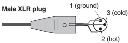
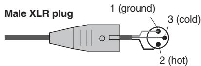
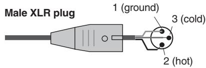
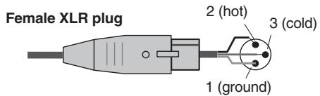
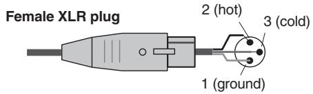
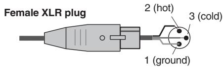
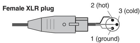
XLR-type connectors are wired as follows (IEC60268 standard): pin 1: ground, pin 2: hot (+), and pin 3: cold (-).
Yamaha cannot be held responsible for damage caused by improper use or modifications to the device, or data that is lost or destroyed.
Always turn the power off when the device is not in use.
The performance of components with moving contacts, such as switches, volume controls, and connectors, deteriorates over time. Consult qualified Yamaha service personnel about replacing defective components.
Included Accessories
PM5D/PM5-D-RH
- Owner's Manual (this document)
- Gooseneck Lamps x 3
Power Supply PW800W Connection Cable
DSP5D
- Owner's Manual (this document)
- AC Power Cord
D-SUB 68-pin Cable 10m× 2
Table of Contents — Operating section
1 Introduction 10
Thank you 10
An overview of the PMSD system 10
Differences between the PM5D model and the PM5D-RH model 11
About the channel structure of the PM5D 12
About the DSP5D 12
Differences with the PM5D. 12
Regarding cascade connections between the PM5D and DSP5D 13
About PM5D Editor and DSP5D Editor 13
Firmware versions 14
Major new functionality in PM5D firmware V2.0 14
Regarding word clock synchronization 15
How this manual is organized. 15
Conventions in this manual. 15
2 Top, front, and rear panels 16
Top panel 16
Rear panel. 18
Front panel 20
DSP5D front panel. 21
DSP5D rear panel 22
3 Basic operation on the PM5D 23
About the various types of user interface 23
User interface in the display. 23
DISPLAY ACCESS section 24
Data Entry section. 24
External user interface 25
Basic operation 26
Click 26
Drag. 26
Drag and drop 26
Accessing a desired screen 27
Moving the cursor. 27
Scrolling the screen 28
Operating the buttons 29
Adjusting the setting of a knob or fader. 29
Assigning a name 30
4 Connections and setup 31
Examples of systems expanded with the DSP5D 31
Example of simple input expansion (PM5D + one DSP5D unit)................................31
PM5D + remotely connected input expansion (PM5D + DCU5D + two DSP5D units). 31
Control from DSP5D Editor (one DSP5D unit + PC) 32
Audio connections 33
Analog audio connections. 33
Analog output connections 34
Digital input/output connections 36
Installing an option card 37
Word clock connections and settings 38
About word clock. 38
Selecting the word clock master. 38
Restoring the current scene to the default state. 40
Switching the target of panel operations (when cascade-connected with the DSP5D) 40
5 Input channel operations 41
About the input channels 41
AD IN section 43
Items in the AD IN section 43
Controlling the input sensitivity and phantom power (+48V) of the head amp 44
INPUT channel strip. 45
Items in the INPUT channel strip. 45
ST IN/FX RTN channel strip 47
Items in the ST IN/FX RTN channel strip 47
FADERFLIP/ENCODERMODEsection 48
Items in the FADER FLIP/ENCODER MODE section 48
Various operations for input channels 49
Selecting the function of the encoders 49
Exchanging the fader and encoder functions 49
Sending a signal from an input channel to the STEREO bus 50
Sending the signal from the input channel to a MIX bus 51
Enabling/disabling pairing. 53
6 Output channel operations 55
About the output channels 55
MIX section 57
Items in the MIX section 57
Operations in the MIX section 57
STEREO A/B channel strip 61
Items in the STEREO A/B channel strip 61
Operations in the STEREO A/B channel strip 62
MATRIX section 63
Items in the MATRIX section 63
Operations in the MATRIX section. 63
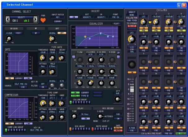
7 Using the Selected Channel section.....65
About the SELECTED CHANNEL section 65
Items in the SELECTED CHANNEL section 65
GROUP 65
CHANNEL SELECT 66
DELAY 66
GAIN/ATTENUATION/Ø (Gain / Attenuation / Phase) ...... 67
NOISE GATE 67
STEREO 68
COMPRESSOR 68
HPF (High Pass Filter) 69
EQUALIZER 69
Operations in the SELECTED CHANNEL section 70
Selecting a channel and editing its parameters 70
Compressor operations. 71
Gate operations 72
EQ/HPF operations. 73
8 Input Patch / Output Patch operations .74
Changing the input patch settings 74
Changing the output patch settings. 75
Inserting an external device into a channel. 77
Connecting an external device for insertion 77
Patching the insert-out and insert-in 78
Directly outputting the signal of an input channel 80
9 Grouping and linking. 81
About DCA Groups and Mute Groups 81
Items in the ASSIGN MODE section. 81
Items in the DCA strip. 81
Using DCA Groups 82
Assigning channels to DCA groups. 82
Controlling DCA groups. 83
Using mute groups 83
Assigning channels to mute groups. 83
Controlling mute groups. 84
Using the Mute Safe function 84
Using EQ Link and Compressor Link 85
10 Scene memory. 87
About scenes 87
Items in the SCENE MEMORY section. 88
Using scene memories 89
Storing a scene. 89
Recalling a scene. 90
Using PREVIEW mode 90
Using the Auto Store function. 91
Using the Direct Recall function 91
Using the Selective Recall function 92
Using the Recall Safe function 94
Using the Fade function 95
Using the Tracking Recall function 96
Using the Global Paste function 97
11 Monitor and Cue. 99
About the MONITOR and CUE sections 99
Using the Monitor function 100
Items in the MONITOR section. 100
Monitoring a signal. 101
Using the Cue/Solo functions 102
Items in the CUE section. 102
About CUE mode and SOLO mode. 102
Cue and Solo groups. 103
Using the Cue function 104
Using the Solo function. 104
12 Talkback and Oscillator 105
About the TALKBACK/OSCILLATOR sections. 105
Items in the TALKBACK/OSCILLATOR sections. 105
Using talkback 106
Using the oscillator 107
13Meters. 108
Items in the meter section 108
Switching the meter display. 108
Switching the metering point 109
Specifying the metering point for input channels. 109
Specifying the metering point for output channels 109
Viewing the gain reduction of the internal gates and compressors 110
Viewing the gain reduction for input channels 110
Viewing the gain reduction for output channels. 110
14 Effects 111
About the internal effects 111
Using an internal effect via a MIX bus 112
Inserting an internal effect into a channel 113
Basic operations in the effect screen 114
Recalling settings from the effect library. 114
Editing the effect parameters 115
Storing settings in the effect library 115
Using the Tap Tempo function 116
Using the Freeze effect 117
15 Graphic EQ and Parametric EQ.....118
Patching the GEQ modules. 118
Expanding the GEQ modules. 119
Basic graphic EQ operations 119
Controlling the graphic EQ from the display 119
Controlling the graphic EQ from the DCA section. 120
Basic parametric EQ operations 121
Controlling the parametric EQ from the display. 121
Controlling the parametric EQ from the SELECTED CHANNEL section. 122
16 Remote control 123
MIDI on the PM5D 123
Using program changes to control events 123
Using control changes to control events. 125
Using the MIDI Remote function 127
Assigning MIDI messages to controllers 127
UsingMIDIremote channels. 131
Transmitting MIDI events when you switch scenes..... 132
Using GPI (General Purpose Interface) 133
Using GPI IN 133
Calibrating the GPI IN ports. 135
Using GPI OUT. 136
17 Using memory cards 138
Using memory cards with the PM5D 138
Saving files to a memory card. 138
Loading files from a memory card 140
18 Surround pan 142
About surround pan 142
Bus configuration and operation in surround mode 143
About the surround buses 143
How the MIX section will operate 143
Basic settings for surround buses 144
Controlling surround pan 145
Notes regarding surround pan 147
19 Other functions 148
Using the user defined keys 148
Items in the USER DEFINED section 148
Assigning functions to the User Defined keys 148
Executing functions assigned to the User Defined keys. 149
Using the FADER MODE section 149
Items in the FADER MODE section. 149
Assigning the FADER MODE section layer 149
Switching the FADER MODE section layer 150
Locking the PM5D (Security functions) 151
Setting the System Password or Console Password 151
Using Parameter Lock or Console Lock 152
Using cascade connections 153
Example of cascade connections between the PM5D and DSP5D. 153
Example of cascade connections between PM5D units 153
Specifying the DSP5D's machine ID number 153
Basic settings for cascade connection 154
Selecting the buses used for cascade connection 156
Connecting the PM5D to your computer via USB 158
Caution when using the USB TO HOST connector 158
Connecting the DSP5D to your computer via Ethernet . 159
Initializing the PM5D's internal memory 160
Initializing the DSP5D's internal memory 160
Adjusting the faders and input/output gain (Calibration) 161
Calibrating the faders. 161
Adjusting the analog input gain (PM5D-RH model only).... 162
Adjusting the output gain. 162
Table of Contents — Reference section
Information shown in the display. 163
Upper part of the display (always visible) 163
Main area of the display 164
Lower part of the display (always visible) 164
Function menu 165
Global functions. 166
EFFECT functions 166
EFFECT PARAM (Effect parameter) screen 166
EFFECT ASSIGN screen. 168
EFFECT LIBRARY screen 169
PLUG-IN screen. 170
GEQ function. 170
GEQPARAM(GEQparameter)screen 170
GEQ ASSIGN screen 173
GEQ LIBRARY screen 174
SCENE function 175
SCENE screen. 175
EVENT LIST screen. 177
SELECTIVE RECALL screen 180
RECALL SAFE screen 182
FADE TIME screen. 184
TRACKING RECALL screen 186
GLOBAL PASTE screen 187
MIDI REMOTE function 188
MIDI SETUP screen 188
MIDI PGM CHANGE (MIDI program change) screen .....190
MIDI CTRL CHANGE (MIDI control change) screen.....191
MIDI REMOTE screen. 192
GPI screen. 194
FADER START screen. 196
TRANSPORT screen 198
DME CONTROL screen 199
UTILITY function 204
PREFERENCE 1/2 screens 204
USERDEFINE screen. 208
SAVE screen 211
LOAD screen 215
FADER ASSIGN screen 217
SECURITY screen. 218
SYS/W.CLOCK function 219
WORD CLOCK screen. 219
MIXER SETUP screen. 221
CASCADE screen. 226
HA (Head Amp) screen. 228
OUTPUT PORT ATT (Output port attenuation) screen.....229
DITHER screen 229
HA LIBRARY screen. 230
METER function 231
INPUT METER screen. 231
OUTPUT METER screen. 232
INPUT GR (Input Gain Reduction) screen. 233
OUTPUT GR (Output Gain Reduction) screen 234
MON/CUE function 234
TALKBACK screen 234
OSCILLATOR screen 236
2TR I/O screen 237
MONITOR screen 238
CUE/SOLO screen 240
Output functions 243
OUTPUT PATCH function 243
OUTPUT PATCH screen 243
INSERT PATCH screen 244
INSERT POINT screen 246
NAME screen. 247
OUTPUT PATCH LIBRARY screen 247
OUTPUT INSERT function 248
INSERT IN MIX 1-24 screen 248
INSERT IN MATRIX/STEREO/MONITOR screen 248
HA LIBRARY screen 249
OUTPUT EQ function 250
EQPARAM(EQParameter)screen. 250
MIX 1-24 screen 251
MATRIX/STEREO screen 251
OUTPUT EQ LIBRARY screen 252
OUTPUT COMP function 253
COMP PARAM (Compressor parameter) screen. 253
MIX 1-24 screen 255
MATRIX/STEREO screen 255
COMP LIBRARY (Compressor library) screen. 256
OUTPUT DELAY function 257
MIX 1-24 screen 257
MATRIX/STEREO screen 257
OUTPUT DCA/GROUP function 258
DCA GROUP ASSIGN screen 258
MUTE GROUP ASSIGN screen 259
EQLINK ASSIGNscreen 260
COMP LINK ASSIGN (Compressor link assign) screen..... 261
MATRIX/ST function 262
MATRIX/ST ROUTING screen 262
MIX to MATRIX VIEW screen. 264
LCR screen 267
SURR SETUP screen 268
OUTPUT VIEW function 270
CH VIEW (Channel view) screen 270
SIGNAL FLOW screen 272
FADER VIEW screen 273
CH JOB (Channel job) screen 274
OUTPUT CH LIBRARY screen 275
Input functions 277
INPUT PATCH function 277
INPUT PATCH screen 277
DIRECT OUT PATCH screen. 278
INSERT PATCH screen 279
INSERT/DIRECT OUT POINT screen 281
NAME screen 282
INPUT PACH LIBRARY screen 283
INPUT HA/INSERT function 283
CH 1-24 (Input channel 1-24) screen. 283
CH 25-48 (Input channel 25-48) screen. 283
STIN/FXRTN (ST IN/FXRTN channel) screen 283
INSERT 1-24 screen. 284
INSERT 25-48 screen. 284
INSERT STIN screen 284
HA LIBRARY screen. 285
INPUT /EQ function 286
EQPARAM(EQparameter)screen 286
EQ 1-24 screen 287
EQ 25-48 switch. 287
EQ STIN/FXRTN screen 287
/ATT 1-48 (Phase/Attenuation 1-48) screen. 288
/ ATT STIN/FXRTN (Phase/Attenuation STIN/FXRTN)
screen 288
INPUT EQ LIBRARY screen 289
INPUT GATE/COMP function 289
GATE PARAM (Gate parameter) screen. 289
COMP PARAM (Compressor parameter) screen 291
CH 1-12 (Input channel 1-12) screen 293
CH 13-24 (Input channel 13-24) screen 293
CH 25-36 (Input channel 25-36) screen 293
CH 37-48 (Input channel 37-48) screen 293
ST IN (ST IN channel) screen. 293
GATE LIBRARY screen 294
COMP LIBRARY (Compressor library) screen 295
INPUT DELAY function 295
CH 1-24 (Input channel 1-24) screen .295
CH 25-48 (Input channel 25-48) screen 295
ST IN (ST IN channel) screen. 295
INPUT DCA/GROUP function 296
DCA GROUP ASSIGN screen 296
MUTE GROUP ASSIGN screen. 297
EQ LINK ASSIGN screen 298
COMP LINK ASSIGN (Compressor link assign) screen .....299
PAN/ROUTING function 299
CH to MIX (Channel to mix) screen 299
MIX SEND VIEW screen 305
FIX ASSIGN VIEW screen 307
LCR screen. 308
SURR PARAM (Surround parameter) screen. 309
SURR VIEW (Surround view) screen 310
M/S screen 311
INPUT VIEW function 311
CH VIEW (Channel view) screen 311
SIGNAL FLOW screen 313
FADER VIEW screen. 314
CH JOB screen 314
INPUT CH LIBRARY (Input channel library) screen............316
Appendices 317
EQ Library List. 317
GATE Library List. 318
Compressor Library List 319
Dynamics Parameters 321
GATE section. 321
COMP section 322
Effect Library List. 324
Effects Parameters 325
Effects and tempo synchronization 336
Scene Memory/Effect Library to Program Change Table.. 337
Parameters that can be assigned to control changes .... 341
Control change parameter assignments 343
NRPN parameter assignments 360
Channel Library List 364
List of parameters available for Pair, Recall Safe or OUTPUT ISOLATION operation 365
MIDI Data Format 368
Warning Messages 377
Error Messages 379
Troubleshooting 380
General Specifications 381
PM5D/PM5D-RH 381
DSP5D 383
Input/output characteristics 384
Electrical characteristics 389
PM5D/PM5D-RH 389
DSP5D 391
Mixer Basic Parameters 393
Pin Assignment 394
Dimensions 395
MIDI Implementation Chart 396
Index 397
PM5D/PM5D-RH Block Diagram .........End of Manual
DSP5D Block Diagram...................................End of Manual
PM5D Level Diagram............End of Manual
PM5D-RH Level Diagram......End of Manual
DSP5D Level Diagram End of Manual
-
The illustrations and screen displays as shown in this Owner's Manual are for instructional purposes only, and may be different from the ones on your device.
-
The company names and product names in this Owner's Manual are the trademarks or registered trademarks of their respective companies.
Operating section
1 Introduction
Thank you
Thank you for purchasing the Yamaha PM5D digital mixing console and/or Yamaha DSP5D digital mixing system. In order to take full advantage of the PM5D/DSP5D's superior functionality and enjoy years of trouble-free use, please read this manual before you begin using the product. After you have read the manual, keep it in a safe place.
An overview of the PM5D system
The PM5D is an expandable digital mixing console with the following features.
Full digital SR mixing system
The PM5D is a full-digital SR mixing console that takes advantage of cutting-edge digital audio processing technology. 24-bit linear AD/DA converters are used to deliver up to 110dB of dynamic range and amazing sound quality. As input channels, it provides 48 monaural channels, four stereo channels, and four stereo channels for effect return. As output channels, it provides 24 MIX channels, eight MATRIX channels, and two STEREO channels. The PM5D can be used in a wide range of applications. You can assign desired channels to be controlled by the eight DCA faders on the panel, and use them as group faders.
PM5D model and PM5D-RH model
In addition to the standard PM5D model that provides manual control of the head amp for each input, the PM5D-RH model is also available, providing programmable control of head amp input sensitivity and phantom power settings. You can choose the model appropriate for your situation and budget.
Cutting-edge user interface
For the input channels and STEREO A/B channels, dedicated channel strips are provided where you can operate the fader, pan, cue, and on/off controls. For MIX channels and MATRIX channels, encoders allow you to control the send level and master level. The PM5D allows quick and intuitive operation just as on an analog mixer. In addition, you can use the SELECTED CHANNEL section to manually control the principal parameters (delay, EQ, gate, compressor) of the desired channel.
Eight effect modules / Twelve graphic EQ modules
Eight high-quality multi-effect modules are built in. Effects such as reverb, delay, multiband compressor, and various modulation effects can be routed via internal buses or inserted into the desired channel. 31-band graphic EQ (alternatively, 8-band parametric EQ) can also be inserted into any channel or any output.
Add-On effects provided as standard
As effect types, the channel strip package (COMP276/276S, COMP260/260S, EQ601), master strip package (OPEN DECK), and reverb package (REV-X) are provided as standard.
Scene memories and libraries
Mix parameters and internal effect settings can be stored in memory as up to 500 scenes for immediate recall. Effects, input/output patching, input channel/output channel settings, internal head amp (PM5D-RH model only) or external head amp settings can be stored in various libraries, independently of scenes.
Digital cascade connection
Up to four PM5D units, or one PM5D and one Yamaha DM2000/02R96 unit, can be cascade-connected to share buses in the digital domain. In particular when PM5D units are cascaded together, operations such as scene saving and recall can also be linked. DME64N can also be used as inserts or as extended signal processors via a cascade connection.
Surround panning
Surround pan functionality allows multi-channel playback systems to be used, letting you place the signal of an input channel in two-dimensional space, or move the sound image forward/backward and left/right. 3-1ch, 5.1ch, and 6.1ch surround modes are available.
I/O card expansion
The rear panel provides four slots in which separately sold mini-YGDAI cards can be installed. AD cards, DA cards, or digital I/O cards can be installed in these slots to add inputs and outputs.
Expansion via the DSP5D
A maximum of two DSP5D digital mixing systems can be cascade-connected to a PM5D to expand the inputs and outputs. You can also connect a Yamaha DCU5D digital cabling unit between the PM5D and DSP5D, and locate the DSP5D remotely.
Differences between the PM5D model and the PM5D-RH model
The PM5D is available as the standard PM5D model or as the PM5D-RH model which allows internal head amp settings to be programmed. These models differ as follows.
PM5D model
- Head amp adjustments (input sensitivity settings, phantom power (+48V) on/off) for the analog inputs (INPUT jacks 1-48, ST IN jacks 1-4) are performed manually, using the controls of the top panel.
- Insert jacks (INSERT IN/OUT jacks) for the monaural analog inputs (INPUT jacks 1-48) are provided on the rear panel, allowing external effect processors to be inserted in the analog domain.
ST IN jacks 1-4 are only for line level. - There is no +48V MASTER switch.
PM5D-RH model
- Head amp adjustments (input sensitivity settings, phantom power (+48V) on/off) for the analog inputs are controlled from within the screen via software. For this reason, the top panel does not have head amp controls; instead, LEDs showing the presence or absence of a signal are provided. Head amp settings can be saved in a library and recalled at any time.
- Insert jacks for the analog inputs are not provided.
- ST IN jacks 1-4 support mic levels through line levels. Phantom power can also be supplied to ST IN jacks 1-4.
- The +48V MASTER switch turns all phantom power (+48V) on/off.
About the channel structure of the PM5D
The PM5D provides the following input channels and output channels.
□ Input channels
This section processes input signals and sends them to the STEREO bus or MIX buses. There are three types of input channel, as follows.
Input channels 1-48
These channels are used to process monaural signals. By default, the input signals from the monaural analog input jacks (INPUT jacks 1-48) are assigned to these channels.
STIN channels 1-4
These channels are used to process stereo signals. By default, the input signals from the stereo analog input jacks (ST IN jacks 1-4) are assigned to these channels.
FX RTN channels 1-4
These channels are used mainly to process the return signals (stereo) from the internal effects. By default, the left/right output channels of internal effects 1 through 4 are assigned to these channels.
Hint
Signal assignments to the input channels can be changed as desired.
About the DSP5D
The DSP5D is a digital signal processing (DSP) system expanding the inputs and outputs of the PM5D.
- Its audio processing capability is equivalent to that of the PM5D-RH. As analog audio input/output jacks, it provides INPUT jacks 1-48, ST IN jacks 1-4, and OMNI OUT jacks 1-24.
- Up to two DSP5D units can be cascade-connected to one PM5D. By connecting it with DSP5D units, the PM5D system can be expanded to a maximum of 168 channels of input (144 channels + 12 ST).
- By switching the control target on the PM5D, the DSP5D can be seamlessly controlled in the same way as the PM5D itself.
- You can use DSP5D Editor application software to remotely control and edit the parameters of the DSP5D. Only Windows computers are supported.
- The DSP5D can be connected to a Yamaha DCU5D digital cabling unit and placed on stage, and operated remotely from the PM5D.
- The front panel provides two slots in which you can install separately sold mini-YGDAI cards to add inputs and outputs in a variety of digital formats.
Output channels
This section mixes the signals sent from input channels etc., and sends them to the corresponding output jacks or output buses. There are three types of output channel, as follows.
- MIX channels 1-24
These channels process signals sent from input channels to MIX buses. In the initial state, output signals are assigned to MIX OUT jacks 1-24. These channels are used mainly for foldback or as sends to external effects. The signals of MIX channels 1-24 can also be sent to the STEREO bus or MATRIX buses. - MATRIX channels 1-8
These process the signals sent from MIX channels or STEREO A/B channels to MATRIX buses, and output them from the MATRIX OUT jacks. This allows MIX channels or STEREO A/B channels to be mixed at the desired balance for output.
STEREO A/B channels
These process the signals sent from input channels or MIX channels, and output them to STEREO OUT jacks A/B. These channels are used as the main stereo outputs. Normally, the same signal is sent from the STEREO A and B channels. However, it is also possible to use the STEREO B channel as the center channel for three-channel L/C/R playback.
Differences with the PM5D
- Connectors and interfaces not found on the DSP5D
- INSERT IN/OUT jacks, MIX OUT jacks, LAMP jacks, MONITOR OUT jacks, CUE OUT jacks, STEREO OUT A/B jacks, MATRIX OUT jacks, 2TR IN ANALOG jacks, TIME CODE INPUT jack, USB TO HOST connector, GPI connector, RS422 REMOTE connector, HA REMOTE connector, MIDI IN/THRU/OUT connectors, 2TR OUT DIGITAL jack, 2TR IN DIGITAL jack, SLOT 3-4, MEMORY CARD slot, MOUSE connector, KEYBOARD connector, PHONES jack
- Controllers such as faders, display devices such as meters. LCD display, +48V MASTER switch (PM5DRH), 75Ω ON/OFF switch
- Connectors and interfaces found only the DSP5D
- OMNI OUT jacks, CASCADE IN/OUT RJ-45 connectors, NETWORK connector, AC IN connector
- POWER switch, mode switch, FAN switch
About the connectors: Since the DSP5D does not have the functionality for the connectors with which DSP5D is not equipped, these functions and connectors are not shown in the screen of the PM5D or DSP5D Editor.
About the interface: Since the DSP5D does not have controllers such as faders or the LCD display, it is operated from the PM5D or DSP5D Editor.
Note
- The explanations in chapter 5 and following of this Owner's Manual are based on the functionality and operating procedures of the PM5D. Supplementary explanations regarding the DSP5D are added only in cases where there is a significant difference in functionality or operating procedure. However, in cases where it is obvious that the above-described differences would make clear differences in operation or in the on-screen display, explanations for the DSP5D will be omitted.
- There are some differences between the PM5D and DSP5D in the I/O cards that are supported. For the most recent information regarding I/O cards, refer to the following Yamaha website. http://www.yamahaaproudio.com/
□ Connection to a computer
The PM5D can be connected to a computer via a USB cable from its USB TO HOST connector, but the DSP5D can be connected to a computer via an Ethernet CAT5 cable from its NETWORK connector.
Regarding cascade connections between the PM5D and DSP5D
By bi-directionally cascade-connecting the PM5D and DSP5D, you can share MIX buses 1-24, STEREO A/B buses, and CUE buses.
For details on cascade connections, refer to p.153.
Note
- Cascade connection with the DSP5D is possible only for PM5D V2.0 or later. If you're using earlier version than V2.0, you will need to upgrade to PM5D V2.0 or later. You can download the most recent firmware from the following Yamaha website. http://www.yamahaaproaudio.com/
- Connectors and interfaces not found on the DSP5D cannot be controlled from the PM5D. For example, the MONITOR [LEVEL] and MONITOR [PHONES] knobs found on the PM5D's top panel are always operated at the level of the PM5D.
□ Controlling the DSP5D
- As the target of control from the PM5D's panel and screen, you can recall machine #1 (PM5D), machine #2
(first DSP5D), or machine #3 (second DSP5D) as desired. For details on operation, refer to p.153.
- Functions assigned to the user-defined keys or the FADER MODE section can be used to select the DSP5D as the target machine to be operated (p.148, 149). Operations can be performed from the panel of the PM5D itself or from DSP5D Editor connected to the DSP5D.
Operation when cascade-connected
Output channels
In general, operations for the output channels of cascade-connected buses will be linked between machines. (You can also specify that they not be linked.) This means that you can operate the system as if it were a single console with an expanded number of inputs. However, since the inserts to output channels will also be duplicated, inserted GEQ modules and effects may also be consumed in duplicate or triplicate. (Separate GEQ modules or effects are inserted into the linked buses on each machine.)
- Scene memories and libraries
Scene memory and library data is stored on each machine. When a scene or a library associated with a scene is stored or recalled, the same scene/library number will be stored/recalled on all machines. When the cascade-connection becomes active, the PM5D's library data not associated with a scene will be sent to each DSP5D to synchronize the libraries. The data on cascade-connected machines can also be saved together to a memory card.
- Effects
The DSP5D provides GEQ modules and effects that are equivalent to those on the PM5D, but since the connections between machines are bus cascade connections, inserts into input channels are limited to being within each machine.
DCA groups / Mute groups
These will operate in tandem for cascade-connected PM5D/DSP5D machines. (p.156)
- CH JOB function
Channel copy operations between the PM5D/DSP5D can be performed from the PM5D front panel. However, channels can be moved using the INPUT VIEW function only within each machine. (p.274, 314)
About PM5D Editor and DSP5D Editor
These programs are application software for operating the PM5D/DSP5D's functionality from a computer. You can use this software to remotely control and edit the parameters of the PM5D/DSP5D.
The USB-MIDI driver (for the PM5D) or DME-N Network driver (for the DSP5D) required for connection with a computer, as well as the PM5D/DSP5D editor, can be downloaded from the following Yamaha website.
http://www.yamahaproaudio.com/
Note
DSP5D Editor supports only Windows computers.
Firmware versions
You can download the most recent firmware from the following Yamaha website.
http://www.yamahaproaudio.com/
For either the PM5D or the DSP5D, you can check the firmware version in the UTILITY function PREFERENCE 2 screen
( p.207)
Major new functionality in PM5D firmware V2.0
The major new functionality and improvements that were added in conjunction with the upgrade to firmware V2.0 are as follows.
Basic functionality and panel operations
- You can now control the DSP5D from the PM5D's panel. (→ p.153)
- On/off operations of the channel selected in the FADER MODE section can now be operated from the DCA [MUTE] key.
- Even if the FADER [FLIP] key is on, you can now use the encoders to control the panning of the signal sent to the MIX buses, the head amp gain, or the attenuators. (p.49)
- If there is no vacant library number when you store the selected scene as NEW, it will now be impossible to save the scene; this prevents an existing library item from being overwritten.
- Remote control of the DME64N/24N (firmware V2.0 and later) is now faster. In particular, operation is faster when connected via an MY16-C or MY16-CII card (supported from V1.2).
- As parameters that can be operated in the screen, MONITOR LEVEL and CUE LEVEL have been added. You can now assign these to the faders of the DCA strip so that the monitor or cue levels can be adjusted. (p.149)
□ EFFECT functions
- Add-On Effects (COMP276/276S, COMP260/260S, EQ601, OPEN DECK) and DE-ESSER have been added.
- A DSP CONFIGURATION option has been added to the EFFECT ASSIGN screen and to the GEQ function GEQ ASSIGN screen, allowing internal effects 1-8 to be used as graphic EQ or parametric EQ. (p.168, 173)
- When the panel [SEL] key is pressed in the EFFECT PARAM screen, or when a [SEL] key is turned on via a linking setting, the effect module inserted in that channel will automatically be selected.
- If you've used the tap tempo function to specify the tempo in the EFFECT PARAM screen and then edited the DELAY parameter, the tempo will now stay unchanged.
GEQ functions
- Options have been added to the GEQ PARAM screen, allowing you to switch a graphic EQ to a parametric EQ. (→ p.170)
-
Not only when the panel [SEL] key is pressed in the GEQ PARAM screen but also when a [SEL] key is turned on via a linking setting, the GEQ module inserted in that channel will automatically be selected.
-
When you insert a GEQ in the GEQ PARAM screen, insert-in will automatically be turned on for that channel, and will be automatically turned off when you remove the GEQ.
SCENE functions
- In the SCENE screen, you can now specify "read-only" scenes that will not be overwritten when you load scenes from a memory card. (p.175)
- In the SCENE screen, a DELAY field has been added, allowing you to specify the timing of the program change or MIDI events that are transmitted when the scene is recalled. (p.175)
- In the SELECTIVE RECALL screen and the RECALL SAFE screen, the ON parameter has been added as a channel parameter that can be included in or excluded from recall operations. (p.180, 182)
- In the SELECTIVE RECALL screen and RECALL SAFE screen, separately from the conventional Recall Safe functionality, an OUTPUT ISOLATION field has been added, so that output channels and parameters to be excluded from recall operations can be stored in SETUP memory (which is not affected by memory card load operations). ( p.180, 182)
SYS/W.CLOCK functions
- In the MIXER SETUP screen, a VIRTUAL SOUND-CHECK button has been added, allowing you to temporarily switch the input signals without affecting the scene memory (input patching). For example, this allows you to perform a sound check using prerecorded material played back by a DAW connected to a slot, instead of the analog input material received via the INPUT jacks. (p.221)
- In the OUTPUT ATT PORT screen, a (phase) button has been added, allowing you to switch the phase between normal and reverse for each output channel or I/O channel output port.
□ UTILITY functions
- In the PREFERENCE 1 screen, a DCA MUTE TARGET option has been added, allowing you to specify that the DCA [MUTE] key will mute the send to the MIX bus. (→ p.205)
- In the PREFERENCE 1 screen, an ATT OPERATION ON PANEL option has been added, allowing you to prevent the panel encoders from operating the attenuators. (→ p.206)
- In the PREFERENCE 1 screen, a MIX SEL/ENCODER MODE LINK option has been added, allowing you to
link selection of MIX channels with selection of MIX SEND SELECT keys. ( p.206)
- In the USER DEFINE screen, functions such as DSP5D CONTROL and ENCODER MODE KEY have been added to the functions that can be assigned to user-defined keys. (p.208)
- In the FADER ASSIGN screen, options have been added, allowing you to use the STEREO/DCA strip section to control the monitor/cue level and on/off status. (p.217)
- In the FADER ASSIGN screen, you can now assign the desired channels of the DSP5D as well. (→ p.217)
- In the SECURITY screen, a LOAD LOCK function has been added, allowing you to disable loading for each type of file. (p.218)
- In the SECURITY screen, a RECALL LOCK option has been added, allowing you to lock parameters so that they will not be changed when a scene or library is recalled. (p.218)
Input/output functions
-
In the OUTPUT PATCH function OUTPUT PATCH screen, you can now change the patching of output channels to MIX OUT jacks 1-24. (p.243)
-
In the OUTPUT PATCH function INSERT POINT screen and the INPUT PATCH function INSERT/DIRECT OUT POINT screen, a SET ALL button and CLEAR ALL button have been added, allowing you to turn all channels on/off in a single operation. (p.246, 281)
- In the OUTPUT PATCH function, a NAME screen has been added, allowing you to assign names to output channels for display in various screens (supported from V1.2). ( p.247)
- In the INPUT VIEW function CH JOB screen, channel settings can now be moved as well as copied. (p.314)
- In the INPUT PATCH function INSERT/DIRECT OUT POINT screen, PRE ATT has been added as a direct output transmit location. (p.282)
- In the PAN/Routing function MIX SEND VIEW screen, the send position (PRE/POST) of the signal sent to the MIX bus is now indicated by the color of the bar graph. ( p.306)
- You can now set a Q of up to 16 for the parametric EQ in the input channels, output channels, and GEQ modules.
- You can now set a threshold level of down to -72dB for an input channel GATE.
Regarding word clock synchronization
The signal used to synchronize digital audio signal processing is called "word clock." Normally, one device transmits a reference word clock signal, and the other devices receive this word clock signal and synchronize to it.
In order to transmit or receive digital audio signals to or from an external device via the PM5D/DSP5D's digital input/output jacks or via a digital I/O card installed in a slot, the word clock must be synchronized between the devices. Be aware that if the word clock is not synchronized, the signals will not be transmitted correctly, and unpleasant noise will occur.
How this manual is organized
This owner's manual is divided into the following three sections.
□ Operating section
This section explains the items on the front and rear panels, connections and setup, and how to operate the PM5D's basic functionality. In particular if you have not operated a digital console before, we recommend that you read chapters 2 through 7 first.
Reference section
This section explains the functionality and operation for all of the PM5D's screens. Refer to this section when you want to learn about the items in the screens.
Appendices
This contains various information such as library lists, parameter lists for the internal effects, the MIDI data format, and lists of warning messages and error messages.
Hint
- For details on synchronizing the word clock of the PM5D/ DSP5D and external devices, refer to the explanation of word clock in Operating section "Chapter 4. Connections and setup" (p.38), and to the Reference Section "WORD CLOCK screen" (p.219).
- As an exception, digital signals that are not synchronized with the PM5D/DSP5D can be input via a digital I/O card that contains a sampling rate converter, or via the 2TR IN/OUT DIGITAL jacks.
Conventions in this manual
In this manual, non-locking panel switches that you press are called "keys," and those that change their on/off status when you push them in (locking types) are called "switches." Of the control knobs on the panel, those that turn from a minimum value to a maximum value are called "knobs," while those that turn endlessly are called "encoders."
Controls located on the panel are enclosed in square brackets [ ] (e.g., [CUE] key, [PAD] switch) in order to distinguish them from the buttons and knobs displayed in the screen. For some controls, the section name is listed before the [ ] (e.g., CH [ON] key, EQ [FREQUENCY] encoder).
Unless otherwise specified, references to the PM5D apply to both the PM5D model and the PM5D-RH model. If specifications differ between the PM5D model and the PM5D-RH model, such differences will be noted each time they occur.
2 Top, front, and rear panels
This chapter explains the names and functions of each part of the PM5D/DSP5D. Details for each section of the top panel are explained in subsequent chapters of this operating section; refer to the appropriate chapter for more information.
Top panel
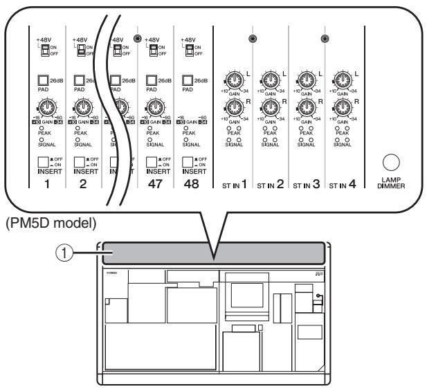
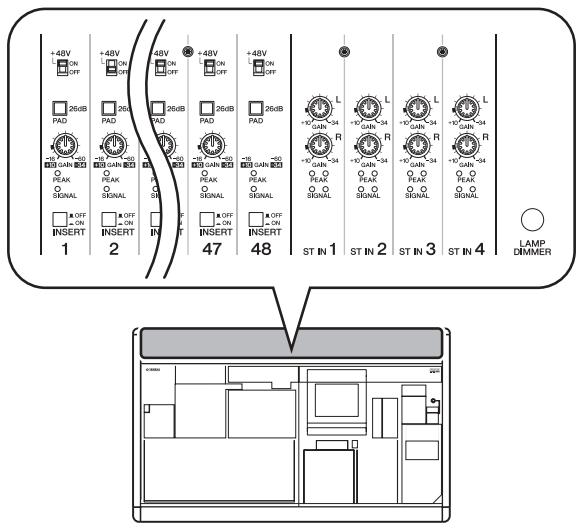
① AD IN section (PM5D model)
In this section you can adjust the sensitivity of the analog signals being input from the rear panel INPUT jacks 1-48 and ST IN jacks 1-4, and switch pad, insert, and phantom power (+48V) on/off (p.43).
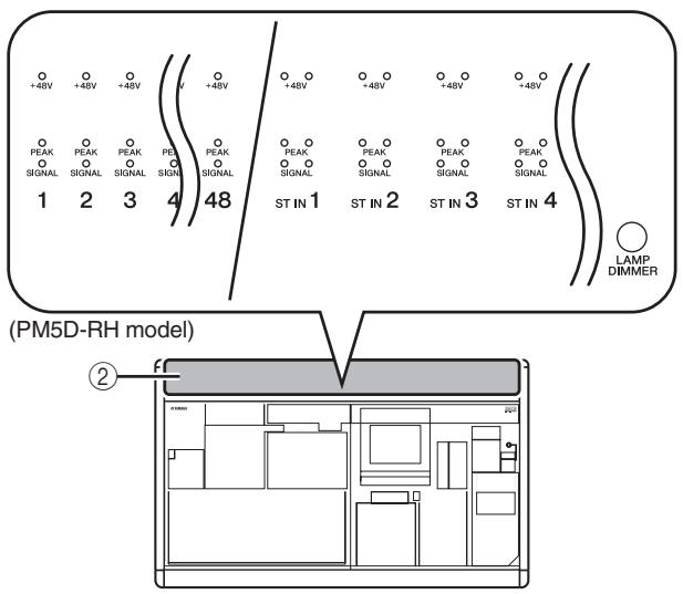
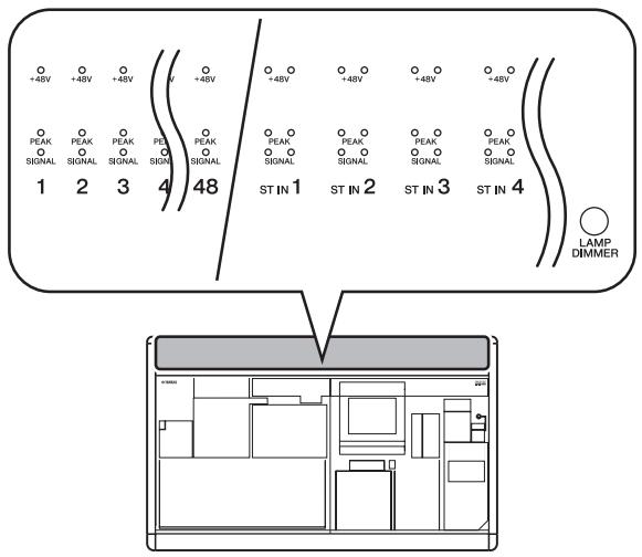
② AD IN section (PM5D-RH model)
This area indicates the presence, peak level, and phantom power (+48V) on/off status of the input signal from rear panel INPUT jacks 1-48 and ST IN jacks 1-4.
Hint
For the PM5D-RH model, input sensitivity and phantom power on/off are controlled by operations in the display (→ p.44).
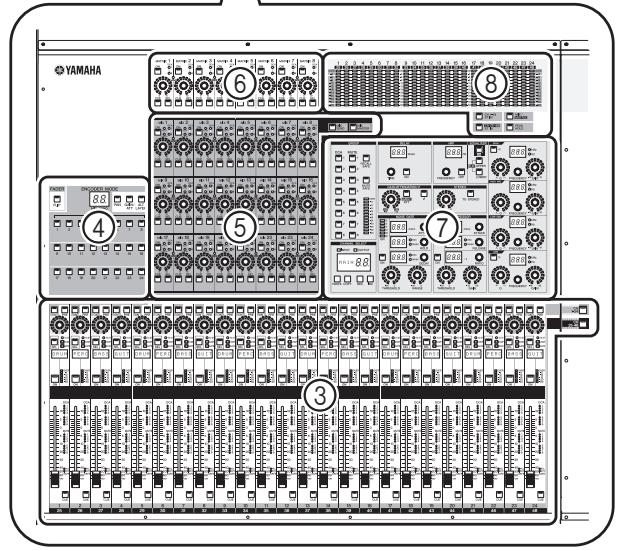
⑧ Meter section
③ INPUT channel strip section
This section controls the principal parameters for input channels 1-48 (p.45).
④ FADER FLIP/ENCODER MODE section
Here you can select the parameters controlled by the faders/encoders of the INPUT channel strip (③) ( p.48).
⑤ MIX section
This section controls the on/off status and send level of the signals sent from input channels to MIX buses, and adjusts the master level of the MIX channels (p.57).
⑥ MATRIX section
This section controls the send level of the signals sent from MIX channels to MATRIX buses, and adjusts the master level of the MATRIX channels (p.63).
⑦ SELECTED CHANNEL section
In this section you can view and control the mix parameters for the currently selected input channel or output channel (p.65).
This section contains peak level meters that indicate the input levels of input channels and the output levels of output channels and cue monitoring, as selected by key operations ( p.108).
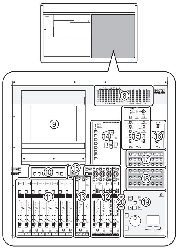
⑨ Display
This display shows the information you need to operate the PM5D, and lets you make system-wide settings and control mix parameters for input and output channels (p.23).
Hint
You can adjust the angle of the display by moving the upper part of the display frame forward or backward.
Note
Before moving the PM5D, you must lower the display all the way back until it is fastened in place.
10 FADER MODE section
Here you can select the combination of channels or DCA groups that will be controlled by the faders of the DCA strip section (⑪) (→ p.149).
11 DCA strip section
From this section you can control the channels assigned to DCA groups 1-8 (p.81).
⑫ ST IN/FX RTN (Stereo in / Effect return) channel strip section
This section controls the principal parameters of ST IN channels 1-4 or FX RTN channels 1-4 (p.47).
⑬ STEREO strip section
This section controls the principal parameters of the STEREO A/B channels (p.61).
14 SCENE MEMORY section
This section stores/recalls mix parameters as scene memories (p.88). Mute operations for mute groups 1-8 are also performed in this section (p.83).
15 CUE/MONITOR section
This section selects the monitor source that is output from the MONITOR OUT jacks, and adjusts the levels. This section also determines the cue point and monitoring method that will be used when you press a [CUE] key for a channel ( p.99).
16 OSCILLATOR/TALKBACK section
This section switches the oscillator or talkback on/off, and adjusts the talkback level ( p.105).
17 DISPLAY ACCESS section
This section selects the functions or screen shown in the display ( p.24).
18 USER DEFINED KEYS sections
This section executes the functions that have been assigned to the User Defined keys [1]–[25] (p.148).
19 Data entry section
This section lets you move the pointer (the arrow displayed in the screen) or cursor (the red frame indicating a selection) in the display and edit the parameter value ( p.24) .
ASSIGN MODE section
This section lets you assign mute groups and DCA groups for control from the panel (p.81).
Rear panel
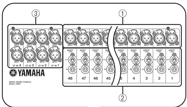
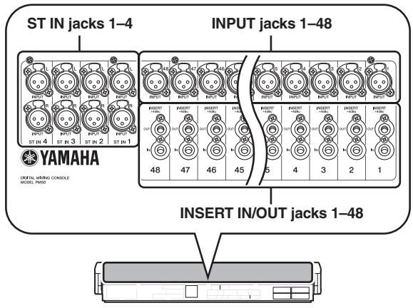
① INPUT jacks 1-48 (PM5D model)
These are balanced XLR-3-31 type input jacks for inputting analog audio signals from line level devices or microphones. Nominal input level is -60dBu to +10dBu .
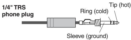
(2) INSERT IN/OUT jacks 1-48 (PM5D model only)
These are balanced TRS phone type input/output jacks for inserting external effects or dynamics processors etc. into INPUT jacks 1-48. Nominal input/output level is +4 dBu.
③ ST IN (Stereo input) jacks 1-4 (PM5D model)
These are balanced XLR-3-31 type input jacks for inputting analog audio signals from line level devices. Nominal input level is -34dBu to +10dBu .

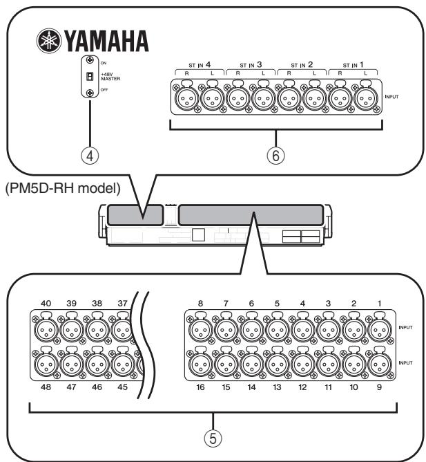
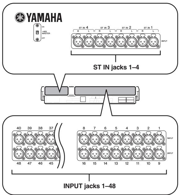
(4) +48V MASTER switch (PM5D-RH model only)
This is the master phantom power (+48V) switch for INPUT jacks 1-48 and ST IN jacks 1-4. If this switch is off, the +48V buttons shown in the display are unavailable.
⑤ INPUT jacks 1-48 (PM5D-RH model)
These are balanced XLR-3-31 type input jacks for inputting analog audio signals from line level devices or microphones. Nominal input level is -62dBu to +10dBu .
⑥ ST IN (Stereo input) jacks 1-4 (PM5D-RH model)
These are balanced XLR-3-31 type input jacks for inputting analog audio signals from line level devices or microphones. Nominal input level is -62dBu to +10dBu .
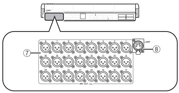
⑦ MIX OUT jacks
These are XLR-3-32 (balanced) jacks that output analog signals such as those that are patched from MIX channels 1-24. Nominal output level is +4 dBu.
⑧ LAMP connector
This is a four-pin female XLR output jack for supplying power to a gooseneck lamp. (These jacks are provided at three locations). The location of these jacks differs between the PM5D model and the PM5D-RH model.
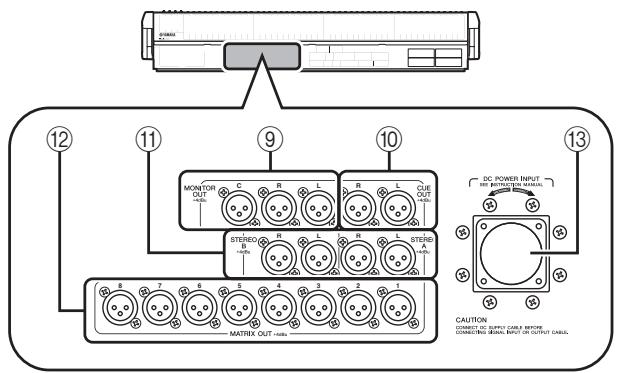
⑨ MONITOR OUT jacks
These are XLR-3-32 (balanced) jacks that output the monitor signal selected in the MONITOR section of the top panel. Nominal output level is +4 dBu.

Note
Although the various output jacks and 2TR IN ANALOG jacks have a nominal input/output level of +4 dBu (maximum level is +24 dBu), an internal switch allows this to be changed to -2 dBu (maximum level +18 dBu) if necessary. For details, contact your Yamaha dealer.
CUE OUT jacks
These are XLR-3-32 (balanced) jacks that output the cue monitor signal from the channel selected by its [CUE] key. Nominal output level is +4 dBu.
⑪ STEREO OUT A/B jackets
These are XLR-3-32 (balanced) jacks that output the analog signals of the STEREO A/B channels. Nominal output level is +4 dBu.
⑫ MATRIX OUT jacks
These are XLR-3-32 (balanced) jacks that output the analog signals of MATRIX channels 1-8. Nominal output level is +4 dBu.
DC POWER INPUT connector
This is a connector for connecting the PW800W power supply. Use the dedicated cable included with the PM5D to make the connection.
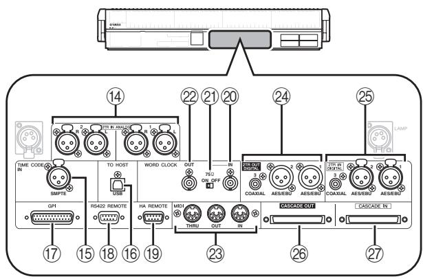
14 2TR IN ANALOG jacks 1/2
These are XLR-3-31 (balanced) jacks that input stereo analog signals from an external source. Nominal input level is +4 dBu.

This is an XLR-3-31 (balanced) jack that receives SMPTE time code (LTC) from an external source.

16 TO HOST connector
This is a USB (type B) connector that allows communication with a computer.
Note
PM5D Editor and the USB-MIDI driver required for connection with your computer can be downloaded from the Yamaha website listed below.
http://www.yamahaproaudio.com/
GPI connector
This is a D-sub 25-pin female connector that allows communication with a GPI-equipped external device.
RS422 REMOTE connector
This is a D-sub 9-pin female connector for remotely controlling an external device that supports the RS422 protocol.
HA REMOTE connector
This is a D-sub 9-pin male connector for remotely controlling an external head amp device (e.g., Yamaha AD8HR or AD824) that supports a special protocol.
WORD CLOCK IN connector
This is a BNC connector for supplying a word clock from an external device to the PM5D.
275Ω ON/OFF switch
This switch terminates the word clock connection. Normally you will leave this ON. If a device made by another manufacturer is connected and word clock cannot be received correctly, try turning this OFF.
22 WORD CLOCK OUT connector
This is a BNC connector for supplying a word clock from the PM5D to an external device.
23 MIDI IN/THRU/OUT connectors
These connectors are used to transmit and receive MIDI messages to and from external MIDI devices. The MIDI IN connector receives messages from an external device, and the MIDI OUT connector transmits messages from the PM5D. Messages received at the MIDI IN connector are retransmitted without change from the MIDI THRU connector.
24 2TR OUT DIGITAL (2 track out digital) jacks 1-3
These jacks digitally output the signals of the STEREO A/B channels. Two types are provided; AES/EBU (XLR-3-32) jacks (1/2) which output AES/EBU format signals, and a COAXIAL (RCA phono) jack (3) which outputs consumer format signals (IEC60958).
25 2TR IN DIGITAL (2 track in digital) jacks 1-3
These jacks input digital audio from external devices such as CD players. Two types are provided; AES/EBU (XLR-3-31) jacks (1/2) which receive AES/EBU format
Front panel
signals, and a COAXIAL (RCA phono) jack (3) which receives consumer format signals (IEC60958).
26 CASCADE OUT connector
This is a D-sub half-pitch 68-pin female connector that can be connected to another PM5D, DSP5D, DCU5D or DME64N for transmission/reception of control signals and transmission of audio signals.
27 CASCADE IN connector
This is a D-sub half-pitch 68-pin female connector that can be connected to another PM5D, DSP5D or DCU5D for transmission/reception of control signals and reception of audio signals.
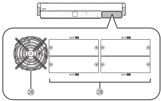
Cooling fan vent
This is the vent for the cooling fans inside the console (two locations). When placing the unit, take care that this vent is not obstructed.
SLOT 1-4
These slots allow separately sold mini-YGDAI I/O cards to be installed to expand the input/output ports.
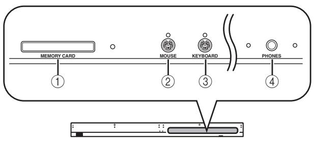
① MEMORY CARD slot
A memory card inserted in this slot can be used to save/load scene memories or library data. You can use PCMCIA Type II flash ATA cards, or CompactFlash cards inserted into a PC card adaptor.
② MOUSE connector
A PS/2 mouse can be connected to this connector and used to perform operations in the display.
③ KEYBOARD connector
A PS/2 keyboard can be connected to this connector and used to input text or perform operations in the display.
④ PHONES (Headphone) jack
This headphone jack lets you monitor the MONITOR OUT or CUE signals.
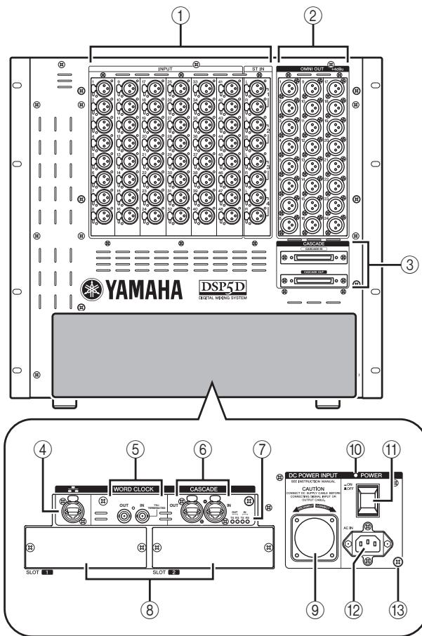
① INPUT jacks 1-48 / ST IN (stereo input)
jacks 1-4
These are balanced XLR-3-31 type input jacks for inputting analog audio signals from line level devices or microphones. The nominal input level is -62dBu to +10dBu . A resettable head amp is provided on all jacks, and head amp settings can be stored in scene memory.
② OMNI OUT jacks 1-24
These are XLR-3-32 (balanced) jacks for outputting analog audio signals. These are used mainly for outputting the MIX/MATRIX/STEREO A/B channel signals. The nominal output level is +4 dBu.
Note
The nominal output level of OMNI OUT jacks 1-24 is +4 dBu (maximum level is +24 dBu), but if necessary, this can be changed to -2 dBu (maximum level +18 dBu) by setting an internal switch (a fee will be charged). For details, please contact your Yamaha dealer.
③ CASCADE IN/OUT connectors
These are D-sub half-pitch 68-pin female connectors to allow connection of the DSP5D, PM5D, DCU5D, and DME64N so that audio signals and control signals can be transmitted and received.
④ NETWORK connector
This connector allows the DSP5D to be connected to a Windows computer via a CAT5 Ethernet cable.
This is used mainly when remotely controlling or editing the DSP5D from the dedicated "DSP5D Editor" application software.
Note
- You should use a CAT5 STP (Shielded Twisted Pair) cable to prevent electromagnetic interference.
- DSP5D Editor and the DME-N Network driver required for connection with your computer can be downloaded from the Yamaha website listed below. http://www.yamahaproudio.com/
⑤ WORD CLOCK IN/OUT connectors
These are BNC connectors used to input and output word clock signals from and to an external device. The input connector is terminated with 75 ohms.
^6 CASCADE IN/OUT connectors
These are RJ-45 connectors that can be connected via a CAT5 Ethernet cable to a DSP5D or DCU5D so that audio signals and control signals can be transmitted and received.
Note
- As connectors, use RJ-45 connectors that are compatible with Neutrik's etherCON® CAT5.
- As cables, you should use CAT5 STP cables (shielded twisted pair cables) to prevent electromagnetic interference.
- To prevent electromagnetic interference, use conductive tape etc. to firmly fasten the metal portion of the connector to the shield of the cable.
- These connectors use EtherSound technology, but are only for use with the PM5D system; they cannot be connected to other EtherSound equipment. For details on the length of cables that can be used, refer to the following website. http://www.ethersound.com/technology/compatibility.php
⑦ IN/OUT [TX]/[RX] LED
When signals are transmitted (TX) or received (RX) via the [CASCADE IN]/[CASCADE OUT] connectors, the corresponding LED will light.
When you use the rear panel mode switch to set the machine ID, the number of LEDs corresponding to the machine ID number will light for five seconds (p.153).
SLOT 1-2
The input/output ports can be expanded by installing separately sold mini-YGDAI I/O cards in these slots.
⑨ DC POWER INPUT connector
A separately sold PW800W power supply can be connected here as an external backup power supply. Use a power supply link cable (PSL360) to make this connection.
10 POWER LED
This will light if power is being supplied to the DSP5D.
⑪ POWER switch
This switch turns the power on/off.
12 AC IN connector
Use the included power cable to supply power to this connector.
⑬ Grounding screw
For safe operation, be sure that the DSP5D is correctly grounded. The included power cable has a three-pin plug, and if the AC outlet is grounded, the DSP5D will be grounded appropriately. If the AC outlet you're using is not grounded, you must be sure to connect this screw to a valid electrical ground. Correct grounding will effectively eliminate noises such as hum and interference.
DSP5D rear panel
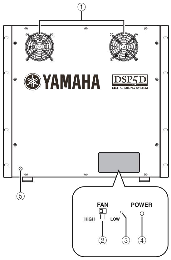
① Cooling fan vents
These are the vents for the DSP5D's internal cooling fans (two locations). When placing the unit, take care that these vents are not obstructed.
② FAN switch
This switches the rotational speed of the DSP5D's internal cooling fans between HIGH and LOW. For normal use, set this to LOW. However if the DSP5D is in a location of high temperature or is outside in direct sunlight, set this to HIGH. You should also set this to HIGH if you feel that the panel is warmer than usual.
③ Mode switch
This switch is used when initializing the settings of internal memory, when updating the firmware in the future, and when setting the machine ID number.
(4) POWER LED
This will light if power is being supplied to the DSP5D.
⑤ Grounding screw
For safe operation, be sure that the DSP5D is correctly grounded. The included power cable has a three-pin plug, and if the AC outlet is grounded, the DSP5D will be grounded appropriately. If the AC outlet you're using is not grounded, you must be sure to connect this screw to a valid electrical ground. Correct grounding will effectively eliminate noises such as hum and interference.
3 Basic operation on the PM5D
This chapter explains the various types of user interface used to operate the PM5D.
About the various types of user interface
Basic parameters such as mixing and editing the sound of each channel can be controlled by the faders and encoders of the top panel. However to make more detailed settings, you will need to access the appropriate "function" and edit the parameter values in the display. The section below explains the various user interface components shown in the display, and how to use them.
User interface in the display
The user interface in the PM5D's display uses the following components.
Pointer
The arrow shown in the display is called the "pointer." Use the pointer to select the parameter you want to control next.
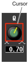
Cursor
The red frame shown in the display is called the "cursor." If the cursor encloses a parameter on the screen, that parameter is selected for operation.
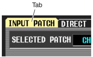
□ Tabs
The screen names shown in the upper left of the display are called "tabs." Tabs are used to switch between screens within the same function.
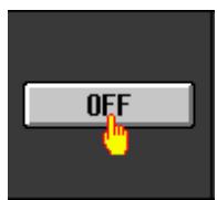
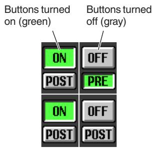
□ Buttons
Buttons in the display are used to switch parameters on/off or to select one of multiple choices. Buttons that are currently on are displayed in green (some buttons are displayed in red or blue); buttons that are turned off are displayed in gray.
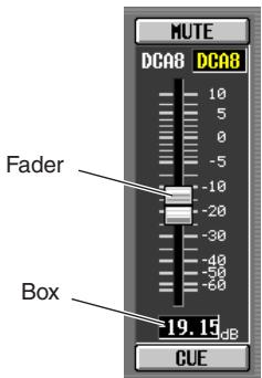
Knobs/Faders/Boxes
Knobs/faders in the display are used to edit parameter values. The current value is shown in the box. Boxes for which
/ buttons are displayed at left and right allow you to edit the parameter by using these buttons. (If editing is not possible, the buttons will be gray.)
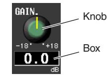
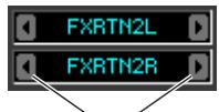
buttons for editing the value
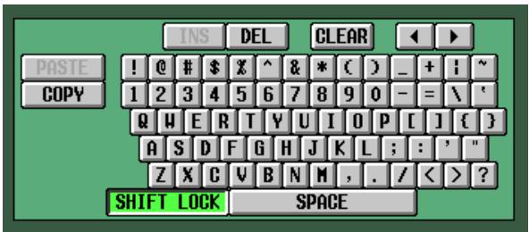
If you want to assign a name to a channel or scene, input characters, numerals, and symbols into the box.

- Character palette
This is a "virtual" keyboard used to input characters, numerals, and symbols into a text input box.
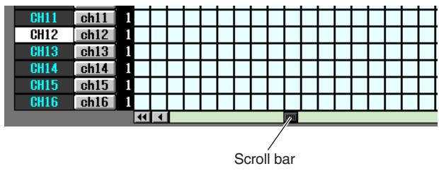
Scroll bar
If the displayed items are too numerous to fit into a single screen, you can use the scroll bar to view the portion that is not currently displayed.
DISPLAY ACCESS section
The DISPLAY ACCESS section contains keys that access the desired function or screen in the display.
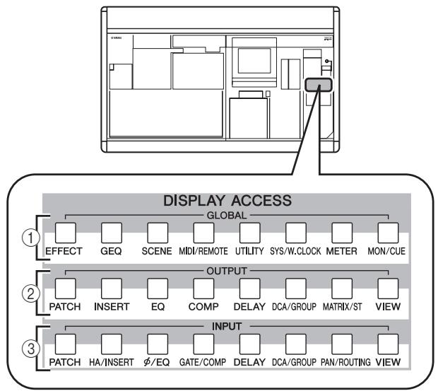
① Global functions
These keys access functions that affect the entire PM5D.
② Output functions
These keys access functions that are related to output channels.
③ Input functions
These keys access functions that are related to input channels.
When you press the key for the desired function, the screen for that function will appear in the display. By repeatedly pressing a key you can cycle through the screens included in that function.
Hint
If you hold down the [SHIFT] key and press a key in the DISPLAY ACCESS section, the screens included in that function will appear in the reverse order (Previous Tab function). You can also use the Previous Tab function by holding down a key in the DISPLAY ACCESS section. If you rapidly press a key twice, you will return to the first screen in that function.
Data Entry section
Controllers used to edit settings and values in the display are gathered into the data entry section.
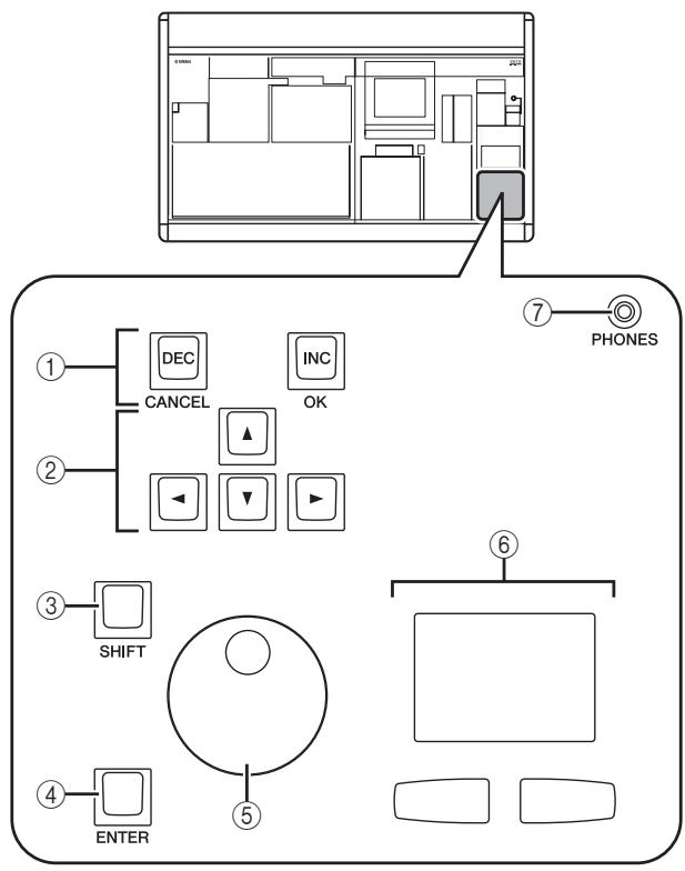
① [DEC/CANCEL]/[INC/OK] keys
Use these keys to increase or decrease the value of the parameter where the cursor is located. If the PM5D has displayed a window asking you to confirm an operation such as recall or store, these buttons can be used instead of the CANCEL button and OK button shown in the window.
② CURSOR [▲]/[▶]/[▲]/[▼] keys
These keys are used to move the cursor to the desired parameter.
③ [SHIFT] key
This key can be used in conjunction with the CURSOR [] / [] / [] / [] keys to move the cursor rapidly, or in conjunction with the [DATA] encoder or [DEC]/[INC] keys to change the parameter value rapidly. If you hold down the [SHIFT] key and press the [ENTER] key, the JOB SELECT window will appear, allowing you to set multiple parameters in a single operation. (When you move the cursor to a parameter for which there is a JOB SELECT window, an indication of "Job Select = [SHIFT] + [ENTER]" will appear.)
(4) [ENTER] key
Use this key to switch a button at the cursor location on/off, or to open a window.
(5) [DATA] encoder
Use this to increase or decrease the value of the parameter where the cursor is located. The parameter value will change more rapidly if you turn the [DATA] encoder while holding down the [SHIFT] key.
⑥ Track pad and left/right buttons
These are used to move the pointer or select the desired parameter. To adjust a knob-type parameter in the display, hold down the left button or right track pad button while you operate the track pad.
⑦ PHONES (Headphone) jack
This is a stereo phone jack for connecting a set of headphones.
External user interface
If desired, you can add the following external user interface components.
Mouse
A PS/2 compatible mouse can be connected to the MOUSE connector located on the front panel of the PM5D and used in the same way as the track pad.
Keyboard
A PS/2 compatible keyboard can be connected to the KEYBOARD connector located on the front panel of the PM5D and used in the same way as the character palette in the display to input characters, numerals, and symbols. The numeric key pad of the keyboard can be used to input numerical values or to recall scenes.
Each key (or combination of keys) has the following function.
Full keyboard
| Key | Function |
| <PageUp> | Same function as the [INS/OK] key of the Data Entry section |
| <PageDown> | Same function as the [DEC/CANCEL] key of the Data Entry section |
| <←>, <→, <↑>, <↓> | Same function as the CURSOR [▲]/[▲]/[▼] keys |
| <Alt> + <PageUp> | Same function as moving the [DATA] encoder clockwise |
| <Alt> + <PageDown> | Same function as moving the [DATA] encoder counterclockwise |
| <Enter> | Same function as the [ENTER] key |
| <Shift> | Same function as the [SHIFT] key |
| <Ctrl> + <←>, <Ctrl> + <→ | Same function as the ↘ buttons of the character palette |
| <Ctrl> + <x> | Copies the text string in the box and clears the copy-source character string (Cut) |
| <Ctrl> + <c> | Same function as the COPY button of the character palette |
| <Ctrl> + <v> | Same function as the PASTE button of the character palette |
| <Insert> | Same function as the INS button of the character palette |
| <Delete> | Same function as the DEL button of the character palette |
| <Home> | Moves the input location in the box to the beginning |
| <End> | Moves the input location in the box to after the last-input character |
| <BackSpace> | Deletes the preceding character that was input in the box (Backspace) |
| <Tab> | Switches to the next screen within the same function |
| Key | Function |
| <Shift> + <Tab> | Switches to the previous screen within the same function |
| <Esc> | Accesses the function menu (if the function menu is already displayed, recalls the last-displayed screen) |
| <Alt> + <0>−<9> | Switch screens within the same function |
Numeric key pad
| Key | Function |
| <0><9> | Input a scene number (if the PREFERENCE 1 screen item USE NUMERIC-KEYPAD is on), input numerical values (if off) |
| <,> | Returns the scene selection number to the number of the scene that was last recalled or stored |
| <++> | Same function as the [▲] key of the SCENE MEMORY section |
| <-> | Same function as the [▼] key of the SCENE MEMORY section |
| </>,<*> | Not used |
| <Enter> | Same function as the [RECALL] key of the SCENE MEMORY section (if the PREFER-ENCE 1 screen item USE NUMERIC-KEY-PAD is on), same function as the [ENTER] key (when off) |
Basic operation
This section explains the basic procedures you can perform in the PM5D's display. In general, you will perform operations in the PM5D's display by combining the operations described here.
Click
Moving the pointer to a specific parameter in the screen and pressing the left/right track pad button (or the left/right mouse button) is called "clicking." Clicking is mainly used to turn an on-screen button on/off, to move the cursor, or to make fine adjustments to a value.
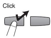
- Track pad
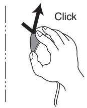
- Mouse
Using the CURSOR [] / [] / [] / [] keys of the data entry section to move the cursor to a desired parameter and then pressing the [ENTER] key is equivalent to clicking. If you are using a PS/2 keyboard, you can perform the same action using the arrow keys and the
Subsequently in this manual, this operation will simply be called "clicking."
Hint
When using the track pad, you can move the pointer to the desired parameter and then tap the track pad to obtain the same result as if you pressed the left button. (This is called the Tapping function.) If you want to use the tapping function, you must enable it in the PREFERENCE 2 screen (UTILITY function) ( p.206) .
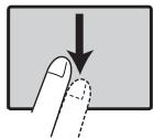
- Track pad
Tapping
Drag
Moving the pointer to a specific parameter in the screen and then holding down the left/right track pad (or mouse) button while moving up/down/left/right is called "dragging." Dragging is used mainly to adjust the value of a knob or fader.
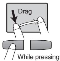
- Track pad
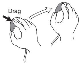
- Mouse
Using the CURSOR [] / [] / [] / [] keys of the data entry section to move the cursor to a desired parameter and then turning the [DATA] encoder (or pressing the [DEC/CANCEL]/[INC/OK] keys) is equivalent to dragging. If you are using a PS/2 keyboard, you can perform the same action using the arrow keys and the
Subsequently in this manual, this operation will simply be called "dragging."
Drag and drop
Moving the mouse pointer to a specific parameter in the screen, dragging to another location in the screen, and then releasing your finger is called "dragging and dropping." Dragging and dropping is used to copy EQ or compressor settings to another channel. Dragging and dropping cannot be performed using the CURSOR keys or keyboard.
Subsequently in this manual, this operation will be called "dragging and dropping."
Accessing a desired screen
A desired function/screen can be accessed in the display using either of the following two methods.
Using the keys of the DISPLAY ACCESS section
1 From the keys of the DISPLAY ACCESS section, press the key corresponding to the desired function.
The most recently operated screen for that function will appear.
2 If you want to switch to another screen within that function, press the same key you pressed in step 1.
If you repeatedly press a key in the DISPLAY ACCESS section, or hold down the [SHIFT] key of the data entry section and press the same key as in step 1, you will return to the preceding screen of the same function.
Using buttons within the display
1 In any screen, click the function name area located in the upper left of the screen.
When you click the function name area, the function menu screen will appear. This screen is the starting point from which you can access the desired screen via operations in the display.
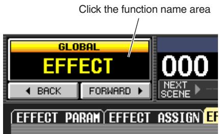
2 In the function menu screen, click the button corresponding to the desired function.
The most recently operated screen for that function will appear.
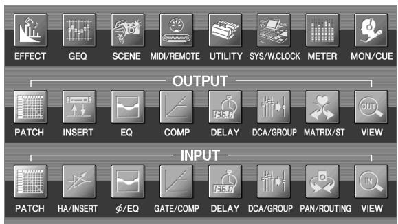
3 Click a tab in the screen to select the desired screen.
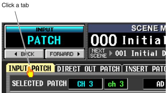
Hint
By clicking the BACK FORMALD buttons located below the function name area you can switch backward through the screens that had been previously displayed for at least two seconds (not including the function menu). Up to the eight most recent screens are remembered.
Moving the cursor
To select a parameter, use the data entry section's controllers or a PS/2 keyboard to move the cursor (the red frame).
Hint
If you are using a mouse or the track pad, the cursor will move when you click on the button or knob of the desired parameter.
1 Use the CURSOR [] / [] / [] / [] keys to move the cursor.
The cursor in the display will move in the direction of the key you pressed. However, it will not move if there is no parameter in the direction of that key.
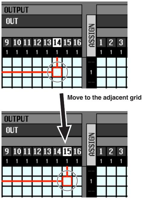
2 To move quickly to the outer edge of the current window or to a different window, hold down the [SHIFT] key and use the CURSOR []/[]/[] /[▼] keys.
You will move from the scroll window in which the cursor is currently located, in the direction of the key you pressed.
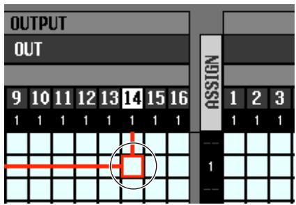
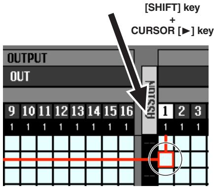
Hint
If the cursor is located on a grid such as in a PATCH screen, turning the [DATA] encoder clockwise will move the cursor toward the right, and turning it counterclockwise will move the cursor toward the left. If you are holding down the [SHIFT] key, turning the [DATA] encoder clockwise will move the cursor downward, and turning it counterclockwise will move the cursor upward.
Scrolling the screen
A scroll bar is displayed if there are more items than can be shown in a single screen. To scroll the screen, drag the box shown in the bar.
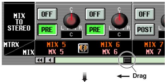
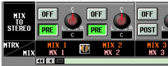
You can also scroll the screen by clicking the vacant portion of the scroll bar or the / buttons or / buttons located at the ends of the scroll bar.
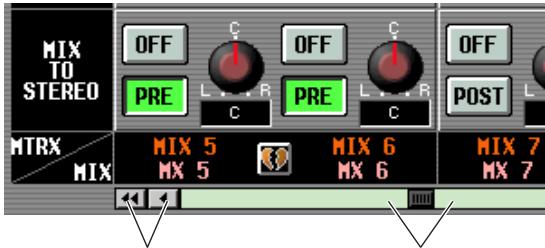
Click these buttons to move the scroll bar box step-wise in the direction indicated. Clicking the / buttons will move in larger steps than clicking the / buttons.
Click in these areas to make the scroll bar box move by a large step in the corresponding direction; the screen will scroll accordingly.
If you move the cursor to the scroll bar and press the [DEC/CANCEL] key or turn the [DATA] encoder counterclockwise, the screen will scroll toward the left (or upward, in the case of vertical scrolling). If you press the [INC/OK] key or
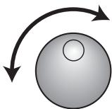
turn the [DATA] encoder clockwise, the screen will scroll toward the right (or downward, in the case of vertical scrolling).
Hint
If the cursor is located at the scroll bar box, holding down the [SHIFT] key and turning the [DATA] encoder will have the same result as clicking the button or button, depending on the direction in which you turn the encoder.
Operating the buttons
Buttons in the display are used to switch parameters on/off or to select one of multiple choices.
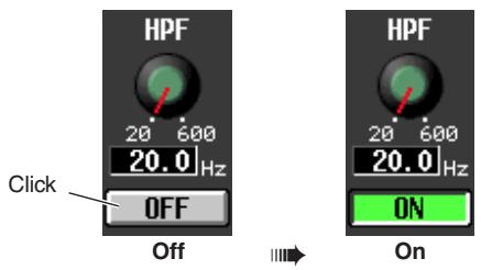
1 Move the pointer to the desired button, and use the left/right buttons of the track pad (or mouse) to click the button.

The button will be switched on/off (or the corresponding button will be selected).
Hint
You can use the CURSOR [<]/[▶][[▲][▼] keys and the [ENTER] key (or the arrow keys and
Hint
When using the track pad, you can also click by tapping the track pad if you have enabled tapping in the PREFERENCE 2 screen (UTILITY function p.206). In this case, the result will be the same as if you pressed the left button of the track pad (or mouse).
Adjusting the setting of a knob or fader
Knobs and faders in the display are used to adjust the value of specific parameters.
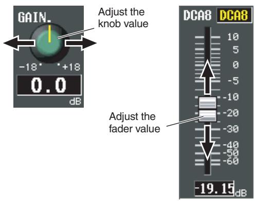
1 Move the pointer to the desired knob/fader, and use the left/right buttons of the track pad (or mouse) to click the knob/fader.
The cursor will move to that location.
2 To increase or decrease the value in steps of 1, click the right button or left button of the track pad (or mouse).
Clicking the right button will raise the value by one step, and clicking the left button will lower the value by one step.
3 To raise or lower the value continuously, use the track pad (or mouse) to drag the knob/fader.
The value will change as you drag the knob or fader left/right or up/down. For a parameter whose knob has a wide range of adjustment, holding down the right button of the track pad (or mouse) as you drag will produce a larger range of change than when using the left button.
Hint
You can also adjust the value by using the [DEC/CANCEL]/[INC/OK] keys, the [DATA] encoder, or the
Assigning a name
On the PM5D you can assign a four-character name to each input channel or DCA group, and assign a title to scene and library data when saving it.
For example, the screen shown below is the LIBRARY STORE window that appears when you assign a name to the INPUT EQ library. To input characters in this screen, use the following procedure.
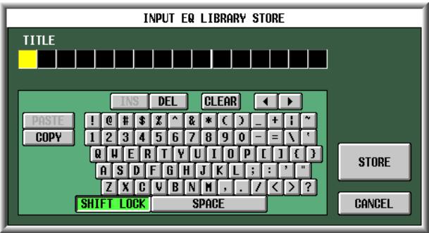
1 Use the character palette (or a PS/2 keyboard) to input a character.
When you click the character palette, a character will be input in the box, and the highlighted area will move to the right.

2 Input the subsequent characters in the same way.
When inputting characters, you can use the following buttons in the character palette.
| INS button | Inserts a space (blank) at the high-lighted position. Pressing the <Insert> key of a PS/2 keyboard will produce the same result. |
| DEL button | Deletes the character at the high-lighted position. Pressing the <Delete> key of a PS/2 keyboard will produce the same result. |
| CLEAR button | Deletes all characters that have been input in the text input box. |
| <→ buttons | Move the highlighted area to left or right. |
| PASTE button | Pastes the character string that was copied to buffer memory by the COPY button. Holding down the <Ctrl> key and pressing the <V> key of a PS/2 keyboard will produce the same result. |
| COPY button | Copies the character string in the box to a temporary buffer memory. Holding down the <Ctrl> key and pressing the <C> key of a PS/2 keyboard will produce the same result. |
| CAPS LOCK button | Switches between uppercase and lowercase alphabetical characters. Uppercase characters can be input while this button is on. |
Note
Copy/paste operations are not possible in some screens. There are also cases in which the paste operation cannot be performed due to the type of character string copied to the buffer memory.
3 When you have finished inputting the name, click the STORE button.
The name you input will be stored.
Hint
- In general, the same procedure applies in screens where you enter names for scenes or other library items.
- If a PS/2 keyboard is connected, you can use it to enter characters.
- If you move the cursor to the text input box and press the [ENTER] key (or click), the input position will move to that point. If the cursor is located at the text input box, you can step through the available characters by turning the [DATA] encoder. If the cursor is located elsewhere, turning the [DATA] encoder will move the selected position. The [INC]/[DEC] keys move the selected position regardless of where the cursor is located.
Note
The number of characters that can be input will depend on the type of data (scene/library) you are saving. You cannot input more than the specified number of characters, or move the highlighted area beyond that range.
4 Connections and setup
This chapter describes examples of expanded systems using the DSP5D, audio input/output connections, and the setup that will be necessary when starting up the PM5D/DSP5D for the first time.
Examples of systems expanded with the DSP5D
- In order to use "escape connections" for expansion, you must first specify the machine ID (p.153) and make cascade connection settings (p.154). If the PM5D and DSP5D are cascade-connected, you'll be able to select the PM5D/DSP5D that will be the target of control from the PM5D's panel (p.40).
Example of simple input expansion (PM5D + one DSP5D unit)
- This system expands the number of input channels to 96 monaural + 8 stereo.
- To make cascade connections, use a D-sub half-pitch 68-pin cable to connect the CASCADE IN connector to the OUT connector of each respective PM5D and DSP5D unit.
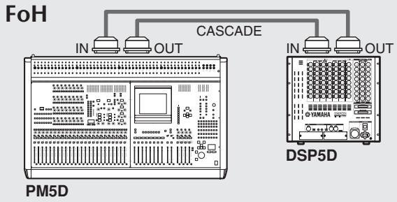
PM5D + remotely connected input expansion (PM5D + DCU5D + two DSP5D units)
- The connection between the PM5D located at FoH and the DSP5D located on the stage is routed through the DCU5D, via Ethernet CAT5 cable and the CASCADE IN and OUT connectors.
- By using two DSP5D units, the number of input channels is expanded to 144 monaural + 12 stereo.
- To make cascade connections between the PM5D and DCU5D, use D-sub half-pitch 68-pin cables to connect the CASCADE IN connectors to the OUT connectors of each respective unit.
- Connections between the two DSP5D units are made using an Ethernet CAT5 cable and a D-sub half-pitch 68-pin cable, each connected from CASCADE IN to OUT of the two units.
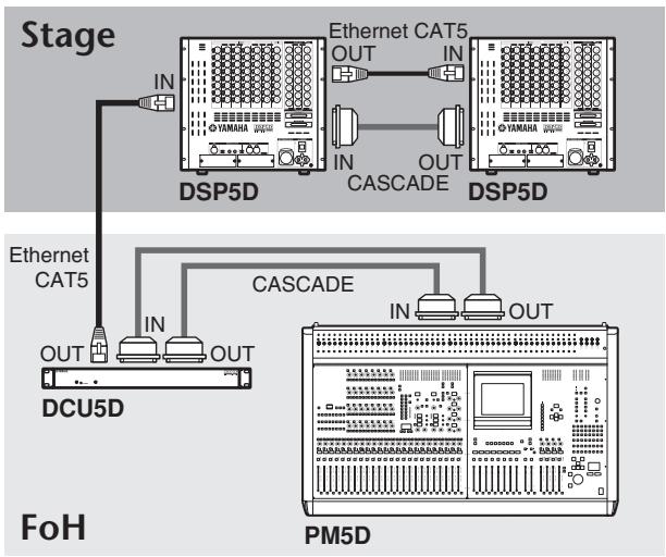
Note
If the PM5D and DSP5D are cascade-connected via the DCU5D and you're not synchronizing to an external word clock being input to the PM5D, you should set the PM5D as the word clock master and the DSP5D as the slave.
Control from DSP5D Editor (one DSP5D unit + PC)
- One DSP5D unit is connected to a PC via an Ethernet CAT5 cable, allowing the DSP5D to be controlled from DSP5D Editor.

Analog audio connections
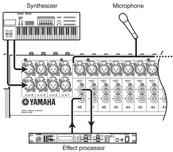
PM5D model
INPUT jacks 1-48 are used mainly to connect microphones or monaural line-level devices. ST IN jacks 1-4 are used mainly to connect stereo line-level devices.
Input signal sensitivity, pad on/off, and phantom power (+48V) on/off are controlled from the top panel AD IN section (p.44).
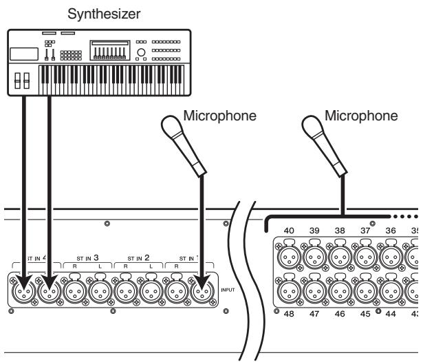
PM5D-RH model
INPUT jacks 1-48 and ST IN jacks 1-4 can both be used to connect microphones or line-level devices.
Input signal sensitivity and phantom power (+48V) on/off are controlled from within the display (p.44). However, all phantom power can be switched on/off as a whole by the rear panel [+48V MASTER] switch.
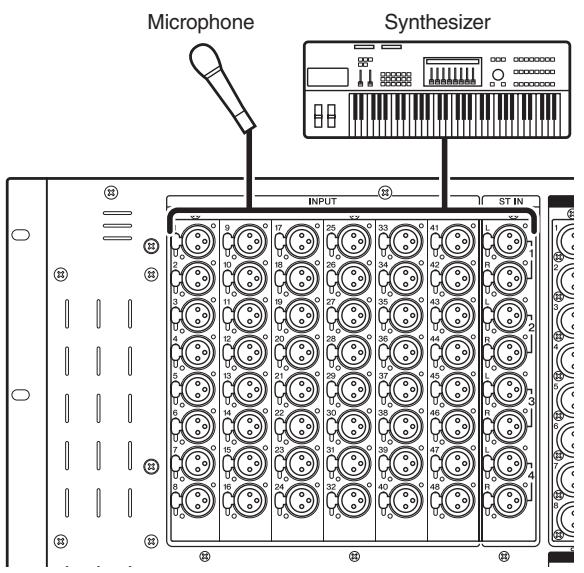
DSP5D
INPUT jacks 1-48 and ST IN jacks 1-4 will accommodate connections ranging from microphones to line level devices.
Each connector is provided with phantom power (+48V) and the input signal sensitivity and phantom power on/off can be operated from the display as on the PM5D-RH
( p.44). The +48V master switch is turned on/off in the SYS/W.CLOCK function MIXER SETUP screen
( p.221)
When the PM5D, PM5D-RH, or DSP5D are in the default state, the input signal from INPUT jacks 1-48 is patched to input channels 1-48, and the input signal from ST IN jacks 1-4 is patched to the ST IN channels. However, you may change this if desired (for details on restoring the default patching p.40).
Analog output connections
PM5D/PM5D-RH
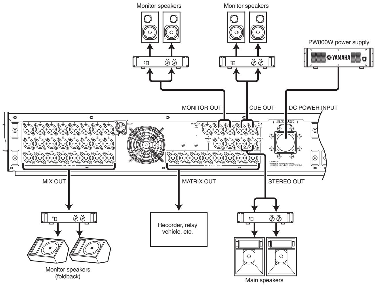
MIX OUT jacks 1-24, MATRIX OUT jacks 1-8, and STEREO OUT A/B jacks respectively output the signal from MIX channels 1-24, MATRIX channels 1-8, and the STEREO A/B channels.
The MONITOR OUT jacks output the monitor signal that is selected in the top panel MONITOR section.
The CUE OUT jacks output the cue monitor signal of the channel that is currently selected by its [CUE] key.
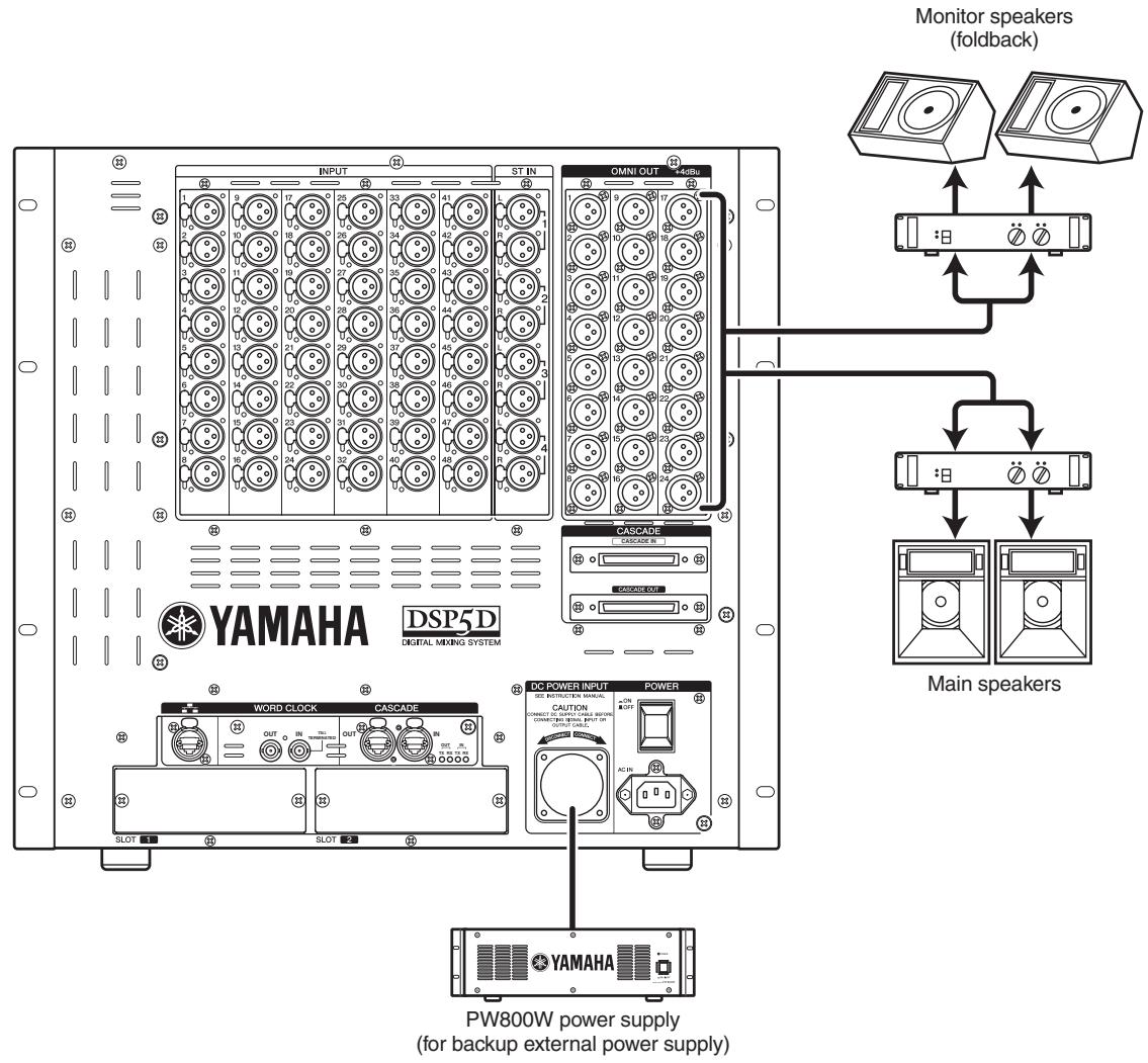
With the default settings, the signals of MIX channels 1-22 are output from OMNI OUT jacks 1-22, and the signals of the STEREO A channel are output from OMNI OUT jacks 23-24. The desired output signal can be patched to each jack; the signals of MIX channels 1-24, MATRIX channels 1-8, STEREO A/B channels, or cue signals can be output from OMNI OUT jacks 1-24.
Digital input/output connections
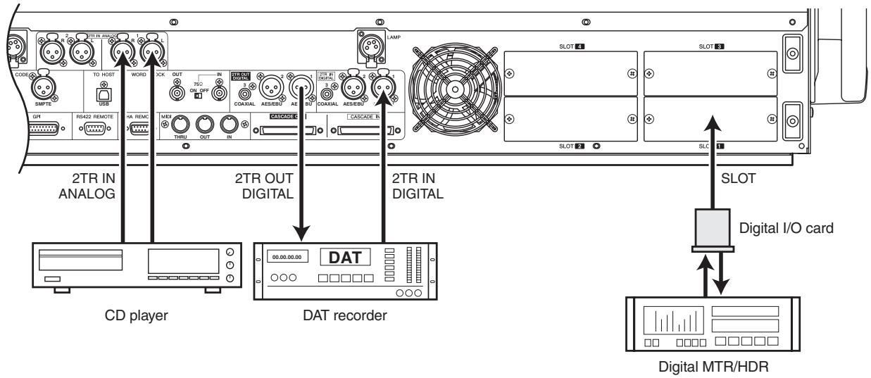
PM5D/PM5D-RH
Use 2TR IN DIGITAL jacks 1-3 to connect digital sources such as CD players or DAT recorders. (To input analog output signals from a CD player or DAT recorder, use 2TR IN ANALOG jacks 1/2.)
Use 2TR OUT DIGITAL jacks 1-3 to send the STEREO A/ B channel signals to a DAT recorder or other digital device.
By installing separately sold mini-YGDAI I/O cards in slots 1-4 (1-2 on the DSP5D) you can add analog input/output jacks to the PM5D/DSP5D or allow connection of digital devices such as digital MTR or HDR units.
The following types of I/O card can be used.
| Card type | Model | Number of channels | Digital format | Bit depth |
| AD card | MY4-AD | 4 | — | 24 bit |
| MY8-AD* | 8 | |||
| MY8-AD24 | ||||
| MY8-AD96 | ||||
| DA card | MY4-DA | 4 | — | 20 bit |
| MY8-DA96 | 8 | 24 bit | ||
| AD/DA card | MY8-ADDA96 | 8 | — | 24 bit |
| Digital I/O card | MY8-AE | 8 | AES/EBU | 24 bit |
| MY8-AEB | ||||
| MY8-AE96 | ||||
| MY8-AE96S | ||||
| MY16-AE | 16 | |||
| MY8-AT | 8 | ADAT | ||
| MY16-AT | 16 | |||
| MY8-TD | 8 | TASCAM | ||
| MY16-TD | 16 | |||
| CobraNet card | MY16-C* | 16 | CobraNet | 24 bit |
| MY16-CII | ||||
| AVIOM Yamaha output card | AVIOM16/o-Y1 | 16 | A-NET | 24 bit |
| AudioService MADI card | MY16MADI64 | 16 | MADI | 24 bit |
| Card type | Model | Number of channels | Digital format | Bit depth |
| AuviTran EtherSound card | AVY16-ES | 16 | EtherSound | 24 bit |
| Waves plug-in DSP card | Y96K* | 8 | ADAT | 24bit |
- is supported only by the PM5D.
For the most recent information regarding I/O cards, refer to the following Yamaha website.
http://www.yamahaproaudio.com/
Note
- In order to send or receive digital audio via the 2TR IN DIGITAL jacks, 2TR OUT DIGITAL jacks, or slots 1-4, the word clock data of the respective signals must be synchronized ( p.38) .
- In order to assign input signals from the 2TR IN DIGITAL jacks, 2TR IN ANALOG jacks, or slots 1-4 to input channels or ST IN channels, you will need to change the input patching (→ p.74).
Installing an option card
Before installing a card, you must check the Yamaha website to make sure that this device is compatible with this card, and to verify the number of cards that can be installed in conjunction with other Yamaha or third-party cards.
Yamaha website: http://www.yamahaproaudio.com
To install an optional mini-YGDAI card, proceed as follows.
1 Make sure that the power is turned off.
2 Loosen the screws that hold the slot cover in place, and remove the slot cover.
Keep the removed slot cover in a safe place.
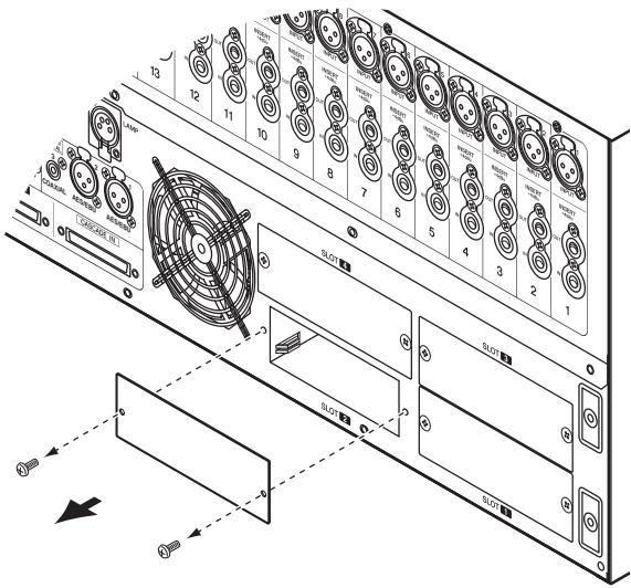
3 Align the edges of the card with the guard rails inside the slot, and insert the card into the slot.
Push the card all the way into the slot so that the connector at the end of the card is correctly mated with the connector inside the slot.
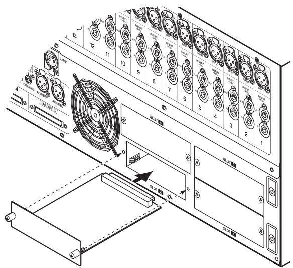
4 Use the screws included with the card to fasten the card in place.
Malfunctions or incorrect operation may occur if the card is not fastened.
Word clock connections and settings
This section explains the word clock settings required in order to send or receive digital audio between the PM5D/DSP5D and an external digital device.
About word clock
When digital audio signals are being sent or received between multiple devices, the devices must process the audio signals at the matching timing. For example if the audio signal processing is not synchronized, the signals will not be transmitted correctly and unpleasant noise will occur even if both devices are set to the same sampling frequency.
The signal used to synchronize digital audio signal processing is called "word clock." Normally, one device transmits a reference word clock signal, and the other devices receive this word clock signal and synchronize to it. (The transmitting device is called the "word clock master" and the receiving devices are called "word clock slaves.")
The word clock can be synchronized between the PM5D/ DSP5D and external devices in either of two ways; you can send/receive a word clock signal by itself, or use the clock data that is included in a digital audio signal.
The WORD CLOCK IN/OUT connectors on the rear panel of the PM5D (front panel for the DSP5D) are used to send/receive a word clock signal by itself. In general, word clock connections can be made in either of the following two ways.
Using daisy-chain connections
In this method, the signal is distributed sequentially; the WORD CLOCK OUT connector of the first device is connected to the WORD CLOCK IN connector of the second device, and so on. Turn all of the PM5D's 75 ON/OFF switches ON. On the DSP5D, this is fixed at 75 ON. This method is not recommended for large systems.
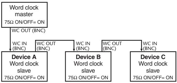
Using a word clock distribution box
In this method, a special word clock distribution box is used to distribute the signal from the word clock master to multiple word clock slaves. Turn ON all of the 75 ON/OFF switches.
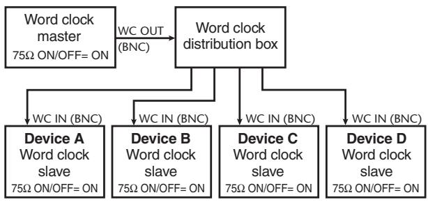
If an external device does not have WORD CLOCK IN/ OUT connectors, the clock data included in the digital audio signal is used. In this case, both the digital audio signal and the clock data are sent from the DIGITAL OUT jack of the word clock master to the DIGITAL IN jack of the word clock slave.
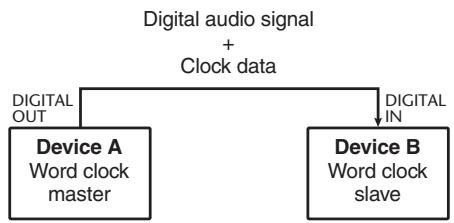
Selecting the word clock master
When digitally connecting the PM5D/DSP5D to an external device, you must select the source that will be the word clock master for the system.
1 Repeatedly press the [SYS/W.CLOCK] key of the DISPLAY ACCESS section until the WORD CLOCK screen appears.
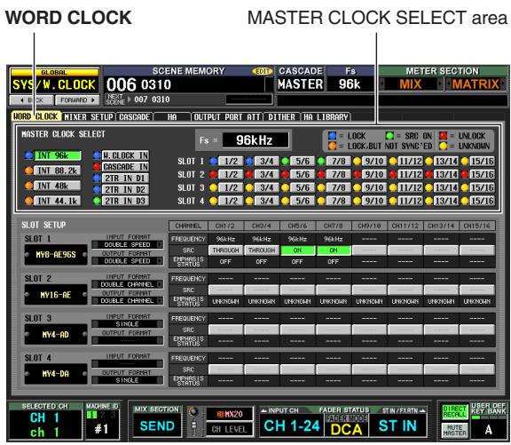
In this screen you can select the master clock, and check the input signal synchronization status for each slot or jack.
Note
When you switch the word clock source, noise may occur due to loss of synchronization. You must lower the level of your monitoring equipment before you perform the following operation.
Use the MASTER CLOCK SELECT area located in the upper part of the screen to select the master clock source. You can choose one of the following sources.
PM5D
| INT 96, INT 88.2, INT 48, INT 44.1 | These settings select the PM5D's internal clock. If you select one of these settings, the PM5D will operate as the word clock master. As necessary, make settings within your external devices so that they will operate as word clock slaves. |
| W.CLOCK IN | The PM5D will follow the word clock signal being input from the rear panel WORD CLOCK IN connector. |
| CASCADE IN | The PM5D will follow the clock data being sent from another PM5D connected to the CASCADE IN connector. |
| 2TR IN D1–D3 | The PM5D will follow the clock data included in the input signal from 2TR IN DIGITAL jacks 1–3. |
| SLOT 1–4 | The PM5D will follow the clock data included in the input signal from a digital I/O card installed in slots 1–4. (You can select a specific pair of adjacent odd-numbered/even-numbered channels.) |
DSP5D
| INT 96, INT 88.2, INT 48, INT 44.1 | These settings select the DSP5D's internal clock. If you select one of these settings, the DSP5D will operate as the word clock master. As necessary, make settings within your external devices so that they will operate as word clock slaves. |
| W.CLOCK IN | The DSP5D will follow the word clock signal being input from the front panel WORD CLOCK IN connector. |
| CASCADE IN (D-sub half-pitch 68-pin connector) | The DSP5D will follow the clock data sent from the other DSP5D, the PM5D, or the DME64N. |
| CASCADE IN (RJ-45 connector) | The DSP5D will follow the clock data sent from the other DSP5D or the DCU5D. |
| SLOT 1-2 | The DSP5D will follow the clock data included in the input signal from a digital I/O card installed in slots 1-2. (You can select a specific pair of adjacent odd-numbered/even-numbered channels.) |
Note
- Sources for which the symbol at the left of the button is red (UNLOCK) or yellow (UNKNOWN) cannot be selected, since a valid clock is not being input or the clock cannot be detected.
- If the PM5D and DSP5D are cascade-connected via the DCU5D and you're not synchronizing to an external word clock being input to the PM5D, you should set the PM5D as the word clock master and the DSP5D as the slave. This means that in this case, you'll select INT for the PM5D, and CASCADE IN for the DSP5D.
2 In the MASTER CLOCK SELECT area located in the upper part of the screen, click a button to select the desired master clock source.
A window will appear, asking you to confirm that you want to switch the master clock.
3 Click the OK button.
The selected word clock master will be enabled. The selected word clock master is remembered even if you turn off the power. As long as the connections have not been changed, you don't have to make this setting again.
Note
- If a digital I/O card (such as the MY8-AE96S) that contains a built-in SRC (Sampling Rate Converter) is installed in slots, you can switch the SRC on/off in groups of two channels. The input signals from channels for which the SRC is turned on do not need to be synchronized with the PM5D/DSP5D's word clock.
- If transferring high sampling rate (88.2 kHz/96 kHz) signals between the PM5D/DSP5D and an external device, you will need to select the transmission method. (For details, refer to p.220)
Restoring the current scene to the default state
When the PM5D/DSP5D is in its default state, the input signals from INPUT jacks 1-48 are patched to input channels 1-48 and the input signals from ST IN jacks 1-4 are patched to the ST IN channels, and can then be output via the STEREO bus or MIX buses.
However, if the PM5D/DSP5D's internal mix parameter settings (referred to as the "current scene") have been modified, the signal of a specific input may not be sent to an input channel, or the EQ or dynamics processors may be set to produce extreme effects.
To initialize the mix parameters from such a state, proceed as follows.
1 Use the SCENE [ ] / [ ] keys of the SCENE MEMORY section to make the scene number indicator show "000".
Scene number "000" is a scene memory containing the default settings.
Hint
If the PM5D and DSP5D are cascade-connected, scene data is stored in both the PM5D and the DSP5D. When a scene is recalled, the same scene number is recalled on all PM5D/DSP5D units.
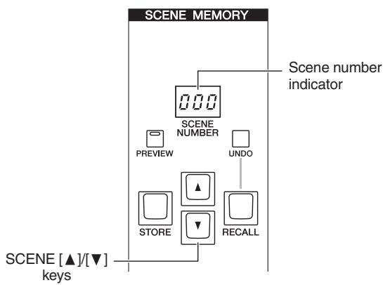
2 Press the [RECALL] key of the SCENE MEMORY section.
Scene number "000" will be loaded, and the current scene will return to the default state.
Note
Be aware that when scene number "000" is loaded, the input patch, output patch, internal effect, and HA (Head Amp) settings will also return to their default state. (However, the word clock master selection is not affected.)
Switching the target of panel operations (when cascade-connected with the DSP5D)
When the DSP5D is cascade-connected, you can switch the target of operations performed from the PM5D's panel, and operate these units while seamlessly switching between the PM5D and DSP5D.
To switch the target of panel operations, use the following procedure. For details, refer to the page reference given for each step.
1 Set the machine ID number of the PM5D and DSP5D ( p.153).
2 In the SYS/W.CLOCK function MIXER SETUP screen, make settings for cascade connections ( p.154).
3 Use one of the following three methods to switch the target of panel operations.
- Using the constantly-displayed screen In the constantly displayed screen, select the machine ID and change it (→ p.164).
- Using a user-defined key In the UTILITY function USER DEFINE screen, assign the DSP5D CONTROL function ( p.148), and use the user-defined key to switch the target of control ( p.149).
- Using the FADER MODE key In the UTILITY function FADER ASSIGN screen, assign a DSP5D layer ( p.149), and use the FADER MODE key to switch the target of control ( p.150).
5
Input channel operations
This chapter explains the functions and operation of each section related to input channels.
About the input channels
The input channel section processes the signals that are input via the input patch section, and outputs them to the STEREO buses or MIX buses. There are three types of input channel, as follows.
Input channels 1-48
These channels are used to process monaural signals. When the input patching is in the default state, the input signals from INPUT jacks 1-48 are assigned to these channels.
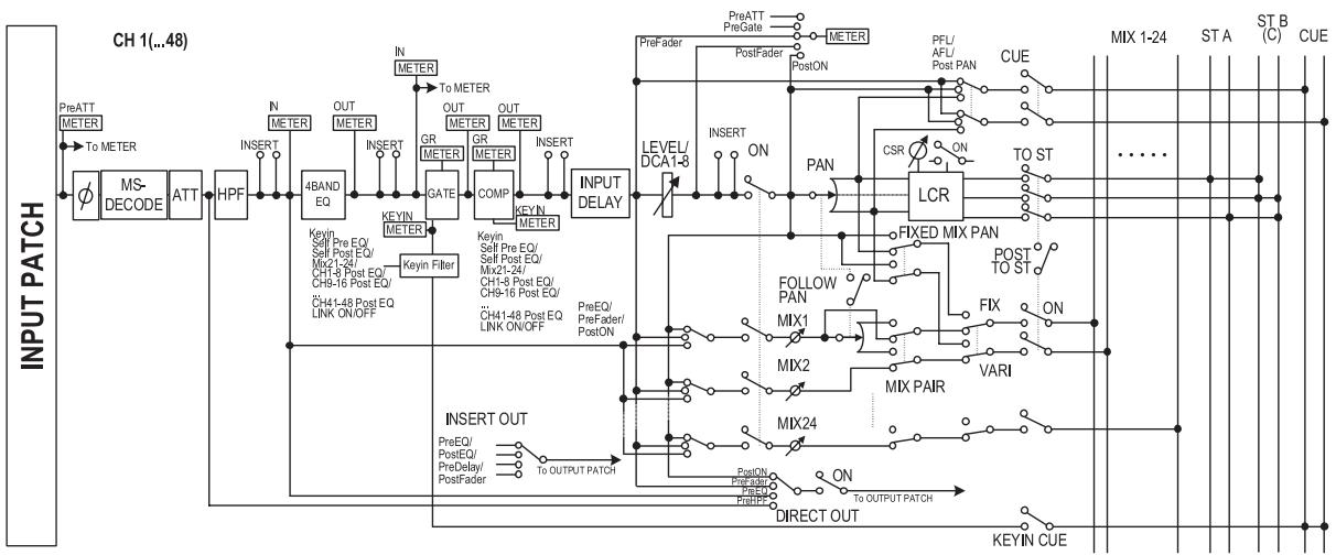
ST IN channels 1-4
These channels are used to process stereo signals. When the input patching is in the default state, the input signals from ST IN jacks 1-4 are assigned to these channels.
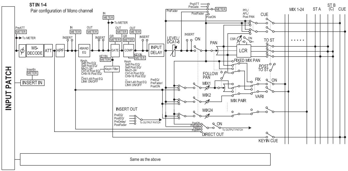
FX RTN channels 1-4
These channels are used mainly to process the return signals (stereo) from the internal effects. When the input patching is in the default state, the left/right channels of internal effects 1-4 are assigned to these channels.
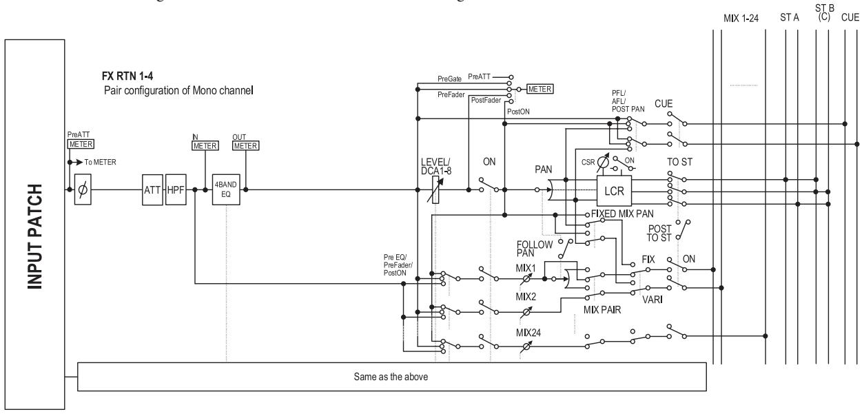
- INPUT PATCH
This assigns an input signal to the input channel.
- (Phase)
Switches the phase of the input signal.
- MS DECODE (Input channels / ST IN channels only)
Switches MS decode processing on/off when an MS mic is connected.
- ATT (Attenuator)
Attenuates/boosts the level of the input signal.
HPF (High Pass Filter)
This is a high pass filter that cuts the region below the specified frequency.
4 BAND EQ (4 band equalizer)
A parametric EQ with four bands; HIGH, HIGH MID, LOW MID, and LOW.
GATE (Input channels and ST IN channels only)
This is a dynamics processor that can be used for gating or ducking.
- COMP (Compressor) (Input channels and ST IN channels only)
This is a dynamics processor that can be used as a compressor, expander, or limiter.
- INPUT DELAY (Input channels and ST IN channels only)
This delays the input signal. It can be used to make fine adjustments in the relative timing between channels.
LEVEL/DCA 1-8
Adjusts the input level of the effect.
- ON (On/off)
Turns the input channel on/off. If off, that channel is muted.
PAN
Adjusts the panning of the signal sent from the input channel to the STEREO bus. If necessary, this pan setting can also be applied to signals sent to two paired MIX buses.
- LCR (Left/Center/Right)
Sends the three-channel signal (left/right channels and a center channel) to the STEREO bus.
- MIX 1-24 (Mix send level 1-24)
Adjusts the send level of the signal sent from the input channel to MIX buses 1-24. As the position from which the signal is sent to the MIX bus, you can choose from the following; immediately before the 4-band EQ, pre-fader, or post-fader.
- INSERT (Input channels and ST IN channels only)
Here you can patch the desired output port and input port to insert-out/insert-in, allowing an external effect processor or other device to be inserted. You can switch the insert-out and insert-in locations.
- DIRECT OUT (Input channel and ST IN channels only)
This can be patched to an output port, and the input signal sent directly from that output port.
METER
This meters the level of the input channel. The level detection point can be switched.
Note
The signal assignments from input patch to input channel can be edited in the INPUT PATCH function INPUT PATCH screen.
To edit the parameters of an input channel, you can either use the panel controllers (e.g., INPUT channel strip, ST IN/FX RTN channel strip, SELECTED CHANNEL section), or access the appropriate screen in the display and edit the parameters in the screen.
The AD IN section AD-converts the signals that are input from the rear panel INPUT jacks 1-48 and ST IN jacks 1-4, and sends them to the input patch section. The structure of this section differs between the PM5D model and the PM5D-RH model.
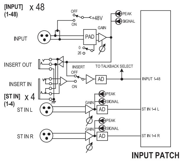
PM5D model
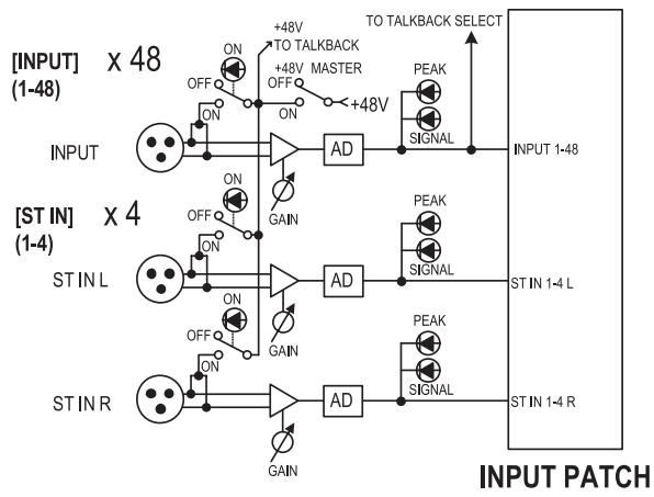
PM5D-RH model
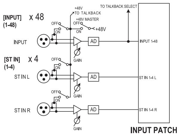
DSP5D
Items in the AD IN section
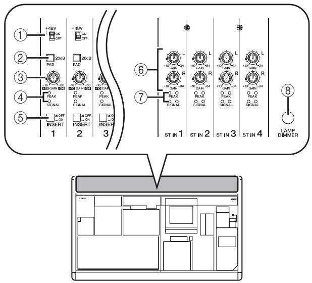
PM5D model
① [+48V ON/OFF] switch
If this switch is on, +48V is supplied to the condenser mic or direct box connected to the INPUT jack 1-48.
② [PAD] switch
If this switch is on, the input level is attenuated by 26 dB.
③ [GAIN] knob
Adjusts the input sensitivity of the input channel. The range of adjustment is -34dBu to +10dBu (when the PAD switch is on) or -60dBu to -16dBu (when the PAD switch is off).
(4) [PEAK]/[SIGNAL] LED
The [SIGNAL] LED will light when the input level reaches 14 dB below nominal level (i.e., 34 dB below clipping level). The [PEAK] indicator will light when the signal reaches 3 dB below clipping level.
⑤ [INSERT ON/OFF] switch
This switch enables/disables the INSERT IN/OUT jack located on the rear panel.
⑥ ST IN [GAIN] knob
Adjusts the input sensitivity of the ST IN channel. The range of adjustment is -34dB to +10dB .
⑦ ST IN [PEAK]/ST IN [SIGNAL] LED
The ST IN [SIGNAL] LED will light when the input level of the ST IN channel reaches 14 dB below nominal level (34 dB below clipping level). The ST IN [PEAK] indicator will light when the signal reaches 3 dB below clipping level.
⑧ [LAMP DIMMER] knob
This adjusts the brightness of the lamp connected to the LAMP connector.
PM5D-RH model
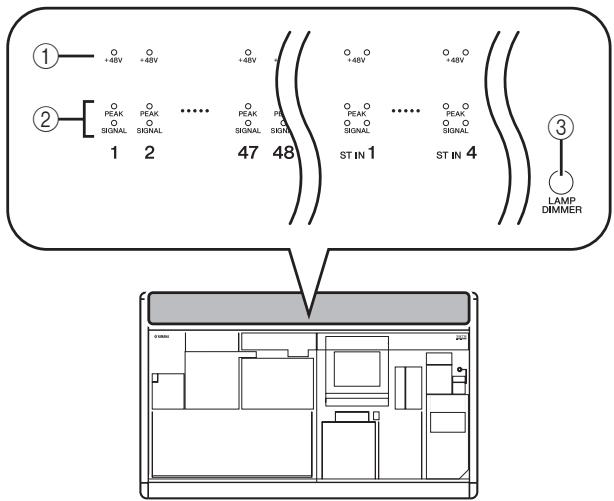
① [+48V ON/OFF] LED
This LED will light if phantom power (+48V) is being supplied to the corresponding INPUT jacks 1-48 or ST IN jacks 1-4. However, +48V will not be supplied unless the rear panel [+48V MASTER] switch is on.
(2) [PEAK]/[SIGNAL] LED
The [SIGNAL] LED will light when the input level reaches 14 dB below nominal level (i.e., 34 dB below clipping level). The [PEAK] indicator will light when the signal reaches 3 dB below clipping level.
③ [LAMP DIMMER] knob
This adjusts the brightness of the lamp connected to the LAMP connector.
On the PM5D-RH model, the AD IN input signal sensitivity and phantom power (+48V) on/off setting for each channel are controlled from within the display. However, the rear panel [+48V MASTER] switch is the phantom power master switch.
Controlling the input sensitivity and phantom power (+48V) of the head amp
You can adjust the input sensitivity and switch phantom power (+48V) on/off for the signals being input from INPUT jacks 1-48 and ST IN jacks 1-4. These operations are performed differently on the PM5D model and PM5DRH model.
Hint
Even if input channels are paired, head amp settings must be made individually.
PM5D model
For the PM5D model, head amp settings are made using the controls of the AD IN section of the panel (p.43).
- The input sensitivity is adjusted by the combination of the [GAIN] knob setting and [PAN] switch on/off setting for that jack.
- To supply phantom power (+48V) to an INPUT jack 1-48, turn on the [+48V] switch corresponding to that jack.
- To enable an external device that is inserted into the INSERT IN/OUT jacks, turn on the [INSERT] switch corresponding to that jack.
PM5D-RH model/DSP5D
On the PM5D-RH model/DSP5D, head amp settings are made by operations within the display.
1 Repeatedly press the [SYS/W.CLOCK] key of the DISPLAY ACCESS section until the HA screen appears.
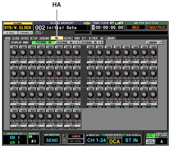
2 In the screen, click the INTERNAL HA button.
The internal head amp settings for INPUT jacks 1-48 and ST IN jacks 1-4 will be displayed.
3 Use the buttons and knobs in the screen to edit the head amp settings.
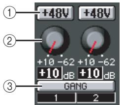
① +48V button
Click this button to switch phantom power (+48V) on/off for that jack.
② GAIN knob
Drag this knob to adjust the input sensitivity of that jack in a range of +10 dB to -62 dB.
Note
The PAD will be switched on or off internally when the gain of the PM5D-RH internal head amp is adjusted between -14 dB and -13 dB. Keep in mind that noise may be generated if there is a difference between the Hot and Cold output impedance of the external device connected to the INPUT connector/ST IN connector when using phantom power.
③ GANG button
If this button is on, the input sensitivity of two adjacent odd-numbered/even-numbered channels will change in tandem, maintaining the current offset value. When making these settings, the LEDs of the AD IN section of the panel will indicate the input signal level and the phantom power (+48V) on/off status.
Note
- On the PM5D-RH model and DSP5D, head amp settings can also be made from the HA/INSERT function CH 1-24 screen, CH 25-48 screen, or ST IN/FX RTN screen (p.283).
- Settings for an external head amp device (AD8HR) can also be made from the screen in the same way as for the internal head amps.
The INPUT channel strip is the section where you can control the principal parameters of the input channels.
This section is layered as shown in the following diagram; choose the CH 1-24 layer when you want to control input channels 1-24, or the CH 25-48 layer when you want to control input channels 25-48.
Note
If the console is cascade-connected to a DSP5D, you can use user-defined keys (→ p.148) or the FADER MODE key (→ p.149) to select a DSP5D layer.
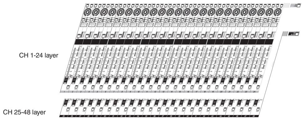
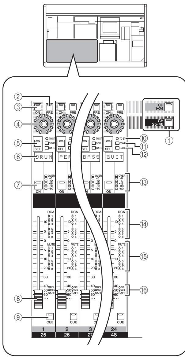
Items in the INPUT channel strip
① [CH 1-24]/[CH 25-48] keys
These keys select the layer (CH 1-24 or CH 25-48) controlled by the INPUT channel strip. The LED of the currently selected layer will light.
(2) [PRE] key
This selects the output location of the signal when send level to MIX bus 1-24 is selected as the encoder function. The pre-fader signal is sent to the corresponding MIX bus if this key is on, and the post-fader signal is sent if this key is off.
③ ENCODER [ON] key
This switches the function currently assigned to the encoder on/off. By default, this switches the signal sent from the input channel to MIX buses 1-24 on/off.
④ Encoder
According to the selection in the ENCODER MODE section / FADER FLIP section (p.48), this encoder adjusts the send level from the input channel to MIX buses 1-24, the panning of the input channel, or the level of the input channel in the layer that is not currently selected. By default, this adjusts the send level to MIX buses 1-24.
⑤ [SEL] key
This selects the input channel that you will control from the SELECTED CHANNEL section or from within the display.
⑥ Name indicator
This displays the name that has been assigned to the input channel.
CH [ON] key
Switches the input channel on/off. If this key is off (LED dark), no signal will be sent from that input channel to the STEREO bus or MIX buses.
⑧ Fader
This 100mm fader adjusts the input level of the input channel.
(9) [CUE] key
This key lets you cue-monitor the signal of the input channel.
10 [TO ST] LED
This LED will light when the signal sent from the input channel to the STEREO bus is on.
(1) [COMP] LED
This indicates the operational status of the compressor for the input channel. This will be dark when the gain reduction amount is 0dB dimly lit when it is 0 - 10dB and lit when it is greater than 10dB .
⑫ [GATE]LED
This indicates the operational status of the gate for the input channel. This will be dark when the gain reduction amount is 0 dB, dimly lit when it is 0-30 dB (or 0-10 dB when ducking), and lit when greater than this.
⑬ Meter LEDs
This is a six-point LED meter that indicates the input level of the input channel. OVER indicates clipping level, and -6 to -60 indicate the level of the signal relative to clipping level (0 dB). The level detection point can be switched.
14 DCA assign LEDs
The LED of the DCA group to which that input channel is assigned will light.
15 MUTE assign LEDs
The LED of the mute group to which that input channel is assigned will light.
[16] [RCL SAFE]/[MUTE SAFE] LEDs
The corresponding LED will light when recall safe or mute safe is enabled for the input channel.
In this section you can control the ST IN channels and FX RTN channels.
This section is layered as shown in the diagram below; choose the ST IN layer when you want to control the ST IN channels, or the FX RTN layer when you want to control the FX RTN channels.
Note
If the console is cascade-connected to a DSP5D, you can use user-defined keys ( p.148) or the FADER MODE key ( p.149) to select a DSP5D layer.
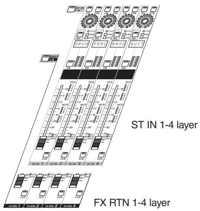
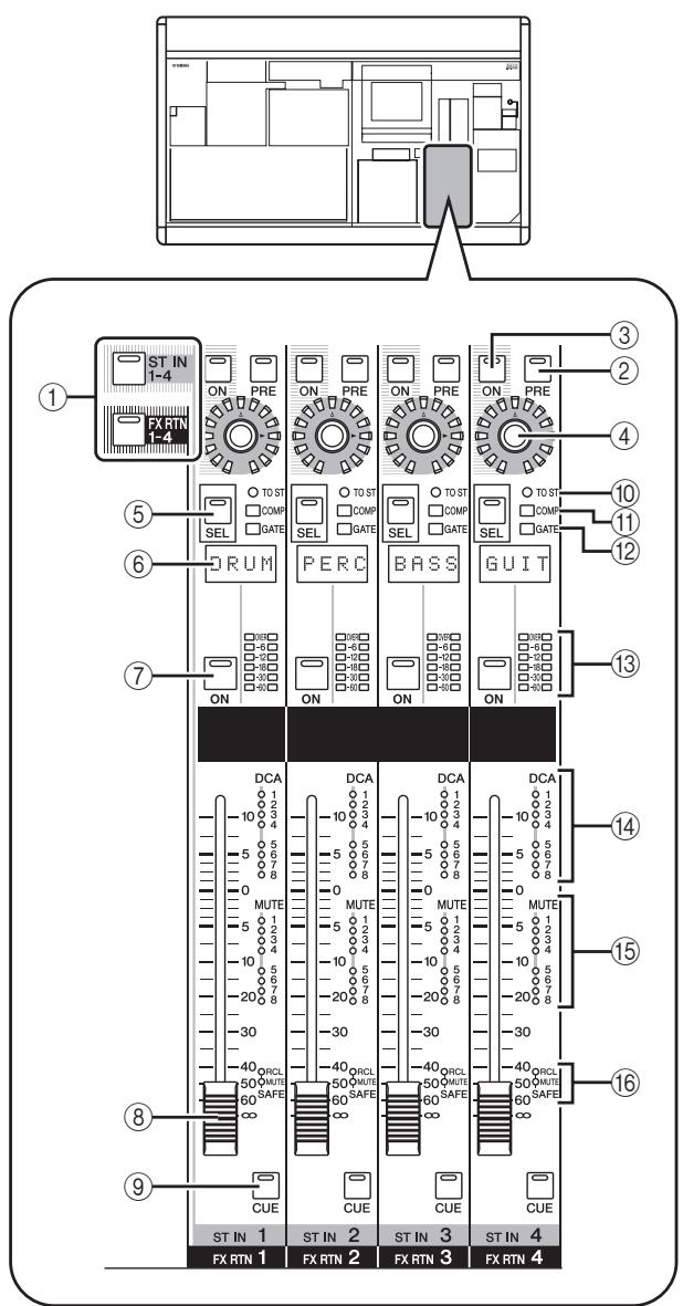
Items in the ST IN/FX RTN channel strip
① [ST IN 1-4]/[FX RTN 1-4] keys
These keys select the layer that will be controlled by the ST IN/FX RTN channel strip. Press the [ST IN 1-4] key to control ST IN channels 1-4, or press the [FX RTN 1-4] key to control FX RTN channels 1-4.
Items ②-⑥ below are the same as in the INPUT channel strip (→ p.45). However since FX RTN channels do not have a gate or compressor, the [GATE] LED (⑫) and [COMP] LED (⑭) are not used.
(2) [PRE] key
③ ENCODER [ON] key
④ Encoder
⑤ [SEL] key
⑥ Name indicator
⑦ CH [ON] key
⑧ Fader
(9) [CUE] key
[TO ST] LED
(1) [COMP] LED
⑫ [GATE] LED
⑬ Meter LEDs
14 DCA assign LEDs
15 MUTE assign LEDs
[16] [RCL SAFE]/[MUTE SAFE] LEDs
FADER FLIP/ENCODER MODE section
In the FADER FLIP/ENCODER MODE section you can change the parameter that is assigned to the encoders, and exchange the parameters assigned to the faders and encoders.
Items in the FADER FLIP/ENCODER MODE section
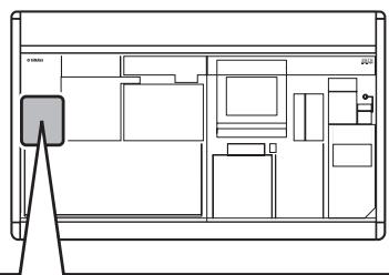
① FADER [FLIP] key
If this key is on, the parameters controlled by the faders and encoders will be exchanged.
② Encoder mode indicator
This indicates the number of the MIX bus (1-24) selected by the MIX SEND SELECT keys (⑥) or the encoder function selected by keys ③ - ⑤
③ [PAN] key
This key selects pan (balance) as the parameter controlled by the encoders. The encoder mode indicator will indicate "Pn" while this key is on.
(4) [GAIN/ATT] key
This key selects input sensitivity to the internal head amp (PM5D-RH model only) or external head amp device (AD8HR or AD824) or attenuation immediately after AD conversion as the parameter controlled by the encoders. The encoder mode indicator will indicate "HA" (if input sensitivity to the head amp is selected) or "At" (if attenuator is selected) while this key is on.
Note
If you don't want it to be possible to select the attenuators, access the UTILITY function PREFERENCE 1 screen, and turn ATT OPERATION ON PANEL off (p.206).
⑤ [ALT LAYER] key
This key selects "input level of the channel not included in the currently selected layer" as the parameter controlled by the encoders. The encoder mode indicator will indicate "AL" while this key is on.
⑥ MIX SEND SELECT [1]–[24] keys
These keys select the MIX bus (1-24) whose send level will be controlled by the encoders. When you press one of these keys, the LED of that key will light, and the encoder mode indicator will show the number of the MIX bus.
Hint
If you turn on any key ③-⑥ , the remaining keys will automatically turn off.
Selecting the function of the encoders
When the PM5D is in the default state, the encoders of the INPUT channel strip and ST IN/FX RTN channel strip are assigned to control send levels to MIX buses 1-24. However you can use the various ENCODER MODE keys to select one of the following as the function of the encoders.
| Key | Encoder function | Display |
| MIX SEND SELECT [1]-[24] keys | Send levels to MIX buses 1-24 | 1-24 |
| [PAN] key | Pan (balance) | Pn |
| [GAIN/ATT] key | Head amp input sensitivity | HA |
| [GAIN/ATT] key | Attenuator | At |
| [ALT LAYER] key | Input level for the currently un-selected layer*1 | AL |
*1. In the INPUT channel strip, the CH 1-24 layer and the CH 25-48 layer are in a “front/rear” relation. In the ST IN/FX RTN channel strip, the ST IN 1-4 layer and the FX RTN 1-4 layer are in a “front/rear” relation.
The currently selected function is shown by the key that is lit and by the encoder mode indicator.
Repeatedly pressing the [PAN] key or [ALT LAYER] key will alternate between the function selected by that key and the MIX bus send level. Repeatedly pressing the [GAIN/ATT] key will alternate between the following three choices; input sensitivity to the internal head amp attenuator MIX bus send level.
Hint
If the FADER section [FLIP] key is on, the functions controlled by the encoders and faders will be exchanged.
Exchanging the fader and encoder functions
You can use the FADER [FLIP] key to exchange the functions assigned to the faders and encoders of the channel strip.
For example with the default setting (FADER [FLIP] key off), the faders control the input channel input levels, and the encoders control the send levels to the MIX buses. If you then press the FADER [FLIP] key to make the LED light, the faders will control the send levels to the MIX buses and the encoders will control the input channel input levels.
Control the send level and on/off status of the signal sent from the channel to the MIX buses
Control the channel input level and on/off status
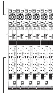
Control the channel input level and on/off status
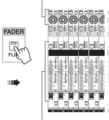
Control the send level and on/off status of the signal sent from the channel to the MIX buses
The function assigned to the controls when the [FLIP] key is on (LED lit) will depend on the current encoder mode as follows.
| [FLIP]key | Encoder mode | Function of each control | |||
| Encoder | ENCODER [ON] key | Fader | CH [ON] key | ||
| Off | MIXSEND | Send level from channel to MIX bus | On/off status of signal sent from channel to MIX bus | Channel (currently selected layer) input level | Channel (currently selected layer) on/off |
| PAN | Pan (balance) | On/off status of signal sent from channel to STEREO bus | |||
| GAIN/ATT | Head amp input sensitivity / attenuator | No function | |||
| ALT LAYER | Channel (currently un-selected layer) input level | Channel (currently un-selected layer) on/off | |||
| On | MIXSEND | Channel (currently selected layer) input level | Channel (currently selected layer) on/off | Send level from channel (currently selected layer) to MIX bus | On/off status of signal sent from channel (currently selected layer) to MIX bus |
| PAN | Pan of the signal sent from channels (of the currently selected layer) to paired MIX buses (invalid if MIX channels are not paired) | Channel (currently selected layer) on/off | |||
| GAIN/ATT | Head amp input sensitivity / attenuator | No function | |||
| ALT LAYER | Send level from channel (currently un-selected layer) to MIX bus | On/off status of signal sent from channel (currently un-selected layer) to MIX bus | |||
Note
The DCA channel strip and STEREO A/B channel strip are not affected by the on/off status of the [FLIP] key.
Sending a signal from an input channel to the STEREO bus
Here's how to use the INPUT channel strip or ST IN/FX RTN channel strip to send an input channel signal to the STEREO bus. The explanation here uses the example of an input channel, but the procedure is essentially identical when using a ST IN channel or FX RTN channel.
1 Make sure that an input source is correctly assigned to the input channel, and that the head amp gain is set appropriately.
2 Make sure that the appropriate CH [ON] key is turned on in the INPUT channel strip, and press the [SEL] key for that channel to make it light.
The [SEL] keys are used to select the channel you want to control.
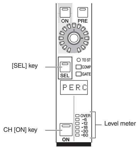
3 In the SELECTED CHANNEL section, press the [TO STEREO] key to make it light.
In the SELECTED CHANNEL section you can make detailed parameters settings for the channel currently selected by its [SEL] key. (For details on the SELECTED CHANNEL section p.65.)
When you turn on the [TO STEREO] key, the signal sent from that input channel to the STEREO bus will be turned on. At this time, the [TO ST] LED of the INPUT channel strip will light.
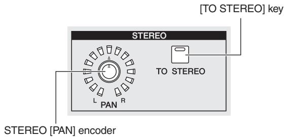
4 Raise the corresponding fader of the INPUT channel strip.
The level of the input signal is shown by the level meter located at the right of the CH [ON] key.
5 Turn on the [PAN] key in the ENCODER MODE section.
6 Use the encoder in the INPUT channel strip to adjust the pan of the input channel.
Note
If you are sending the signal from a ST IN channel / FX RTN channel to the STEREO bus, you can repeatedly press the [SEL] key to switch between L/R channels, and make pan settings for each channel.
7 In the STEREO A/B channel strip, turn the STEREO A [ON] key and STEREO B [ON] key on (LED lit).
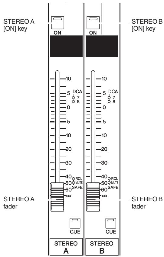
8 In the STEREO A/B channel strip, raise the [STEREO A]/[STEREO B] faders.
The signal sent to the stereo bus will be routed through the STEREO A/B channels and output from the STE-REO OUT A/B jacks.
Sending the signal from the input channel to a MIX bus
Signals from input channels or ST IN/FX RTN channels can be sent to the desired MIX bus. This can be done either by specifying the send level sent from all input channels to a specific MIX bus, or by specifying the send level sent from a specific input channel to all MIX buses.
The explanation here uses an input channel as the send-source, but the procedure is the same when using a ST IN channel or FX RTN channel.
To send signals from all input channels to a specific MIX bus
1 Use MIX SEND SELECT [1]–[24] keys of the ENCODER MODE section to select the destination MIX bus.
The selected key will light, and the encoder mode indicator will show the number of the destination MIX bus. In this state, the encoders of the channel strip adjust the send level to the MIX bus. Make sure that the FADER [FLIP] key is dark.
2 Turn the encoders of the INPUT channel strip.
When MIX SEND is selected as the encoder mode, you can use the encoders of the INPUT channel strip to adjust the level of the signal that is sent to the currently selected MIX bus from the corresponding input channel.
The LEDs around the periphery of the encoder indicate the approximate send level.
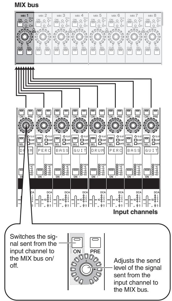
3 To turn off the signal sent from a specific channel to the MIX bus, press the ENCODER [ON] key for that channel to turn it off.
Press the same key once again to turn it back on.
Note
If the send-destination MIX bus is set to FIXED mode ( p.299) , the encoders have no effect; the signal can only be switched on/off by the ENCODER [ON] key.
4 In the same way, select a different send-destination MIX bus, and use the encoders of the INPUT channel strip to adjust the send levels to it.
To send signals from a specific input channel to all MIX buses
Press a [SEL] key of the INPUT channel strip to select the send-source channel.
2 In the MIX section, press the [MIX SEND] key to make it light.
The MIX section lets you control the signals sent to MIX buses 1-24 and the signals output from MIX channels 1-24. (For details, refer to p.57) When the [MIX SEND] key is lit, you can use the encoders of the MIX section to control the send levels from the currently selected input channel to MIX buses 1-24.
![YAMAHA PM5D-RH - In the MIX section, press the [MIX SEND] key to make it light. - 1](/content/2025/01/115055/images/514577b2134056f0118a211800fabd58337d5aba99f567b8f2c179a9d8071858.jpg)
Hint
When the [MIX MASTER] key of the MIX section is lit, you can hold down the [SEL] key of an input channel to make the [MIX SEND] key light (the [MIX MASTER] key will go dark). In this state, you can use the encoders of the MIX section to adjust the send levels from the selected channel to MIX buses 1-24.
3 Turn the MIX encoders to adjust the send levels to the MIX buses.
The LEDs around the periphery of the encoder indicate the approximate send level.
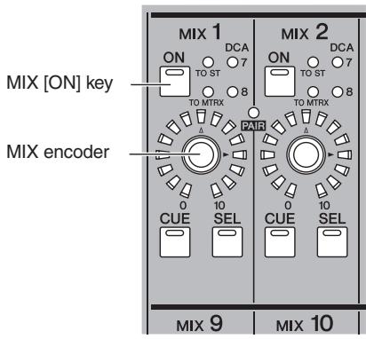
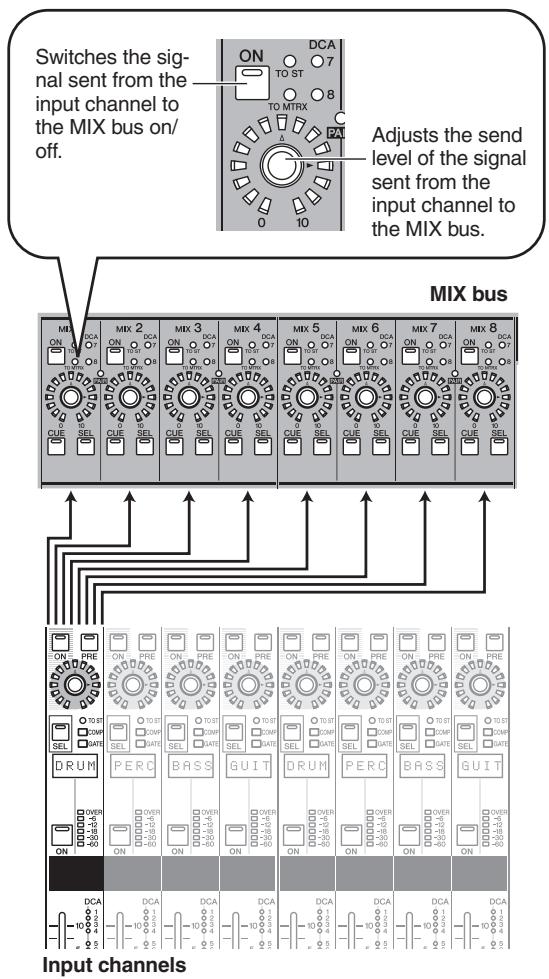
4 To turn off the signal sent from that channel to a MIX bus, press the MIX [ON] key to turn it off.
Press the MIX [ON] key once again to turn it back on.
Note
MIX buses can be switched (in units of two adjacent odd-numbered/even-numbered MIX buses) between VARl type (send levels are variable) and FIXED type (send levels are fixed). (For details on switching the type p.299
- When sending a signal from an input channel to a VARI type MIX bus
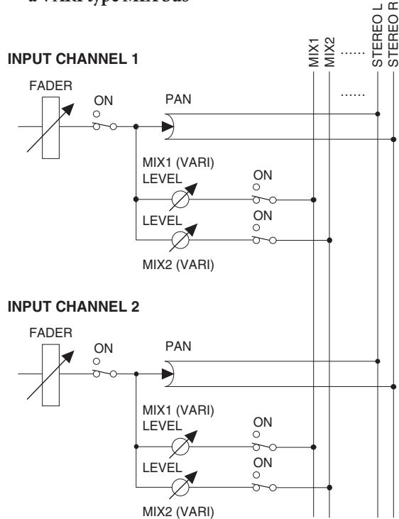
- When sending a signal from an input channel to a FIXED type MIX bus
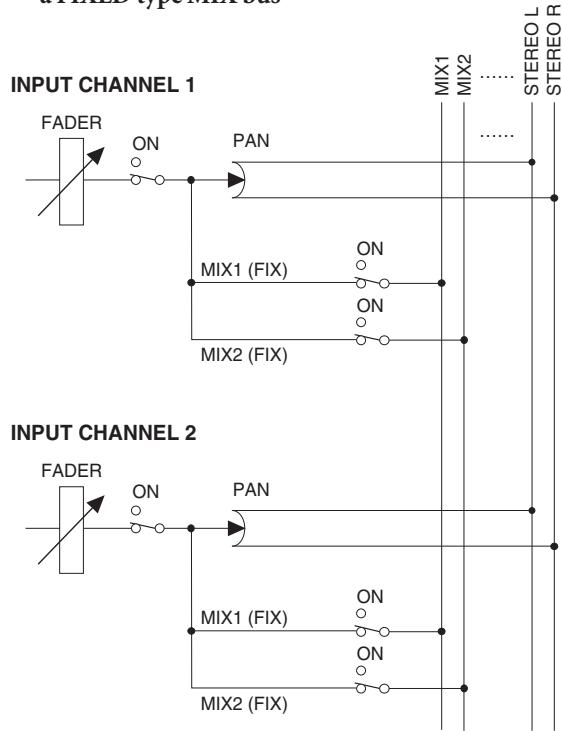
If the send-destination MIX bus is set to FIXED mode, the MIX encoders have no effect; the signal can only be switched on/off by the MIX [ON] key.
Enabling/disabling pairing
Monaural input channels can be paired to link their principal parameters. There are two types of pairing; you can use only one type.
Horizontal pair mode
This mode pairs adjacent odd-numbered/even-numbered channels (default setting).
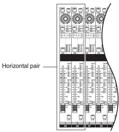
Vertical pair mode
This mode pairs channels of different layers that share the same fader.
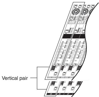
Hint
Input channels that are paired will have their parameters linked except for head amp, delay, pan, attenuation, and phase.
Note
If the PM5D is cascade-connected to the DSP5D, pairing can be specified only within each individual machine.
Using horizontal pairing
Here's how to enable or defeat pairing for adjacent odd-numbered/even-numbered channels.
1 To enable pairing, hold down the [SEL] key of one of the adjacent odd-numbered/even-numbered channels, and press the [SEL] key of the other channel.
The parameters of the channel you pressed first will be copied to the subsequently-pressed channel.
Hint
The copy-source channel is determined by the order in which you press the [SEL] keys. For example if you hold down the channel 1 [SEL] key and press the channel 2 [SEL] key, the channel 1 parameters will be copied to channel 2.
2 To defeat pairing, hold down the [SEL] key of one of the paired channels and press the [SEL] key of the other channel.
Note
If you are unable to enable/defeat pairing by using the above procedure, make sure that MAKE PAIR ON PANEL is turned on in the UTILITY function PREFERENCE 1 screen ( p.206) .
Using vertical pairing
Here's how to enable or disable pairing for channels of different layers that share the same fader.
1 Repeatedly press the [SYS/W.CLOCK] key of the DISPLAY ACCESS section until the MIXER SETUP screen appears.
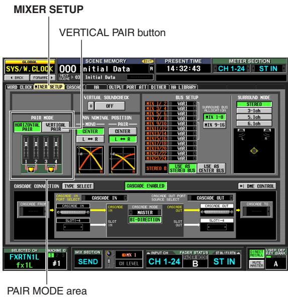
2 Click the VERTICAL PAIR button in the PAIR MODE area to turn it on.
A window will appear, asking you to confirm that you want to change the pair mode.
3 Click the OK button.
Now you can use "vertical pair" mode.
When you switch to "vertical pair" mode, new numbers will be assigned to the input channels. For details, refer to p.221.
You can return to "horizontal pair mode" by clicking the HORIZONTAL PAIR button to turn it on.
Hint
When you switch between vertical pair mode and horizontal pair mode, the input channel numbers will change, but the channel names and parameter values will not change.
4 Hold down the [SHIFT] key of the data entry section, and press the [SEL] key of one of the channels you want to pair.
A window will appear, allowing you to select how pairing will be handled.
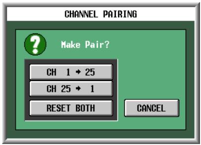
5 Click the appropriate button to choose the source/destination for the parameters that will be copied.
The channels will be paired as you specify.
Hint
If you click the RESET BOTH button, the parameters of both channels will be reset to their default value.
6 To defeat pairing, hold down the [SHIFT] key and press the [SEL] key of one of the channels.
A window will ask you to confirm that you want to defeat pairing. Click the OK button to defeat pairing.
6
Output channel operations
This chapter explains the functions and operation of each section related to output channels.
About the output channels
Output channels mix the signals sent from input channels etc., and send them to the corresponding output jacks or output buses.
There are three types of output channel, as follows.
Note
The DSP5D does not have MIX OUT jacks, MATRIX OUT jacks, or STEREO OUT jacks. Output channels are assigned to OMNI OUT jacks for use.
MIX channels 1-24
Signals sent from input channels to MIX buses are sent via these channels to the MIX OUT jacks 1-24 or the STEREO/MATRIX buses. If the output patching is in its default state, the PM5D assigns MIX channels 1-24 to MIX OUT jacks 1-24, and the DSP5D assigns MIX channels 1-22 to OMNI OUT jacks 1-22.
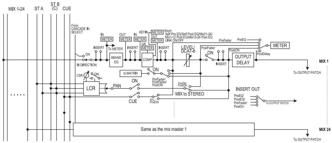
STEREO A/B channels
The signals sent from input channels or MIX channels are sent via these channels to STEREO OUT jacks A/B.
If the DSP5D's output patching is in its default state, the STEREO A channel is assigned to OMNI OUT jacks 23-24.
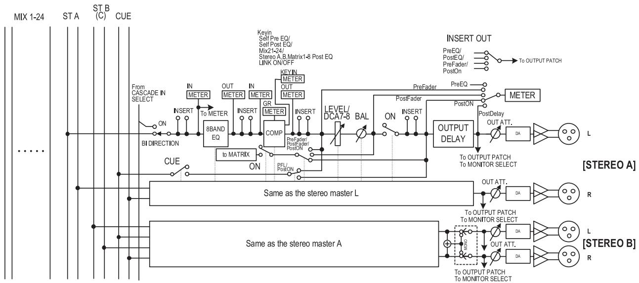
MATRIX channels 1-8
The signals sent from MIX channels or STEREO A/B channels to MATRIX buses are sent via these channels to the MATRIX OUT jacks.
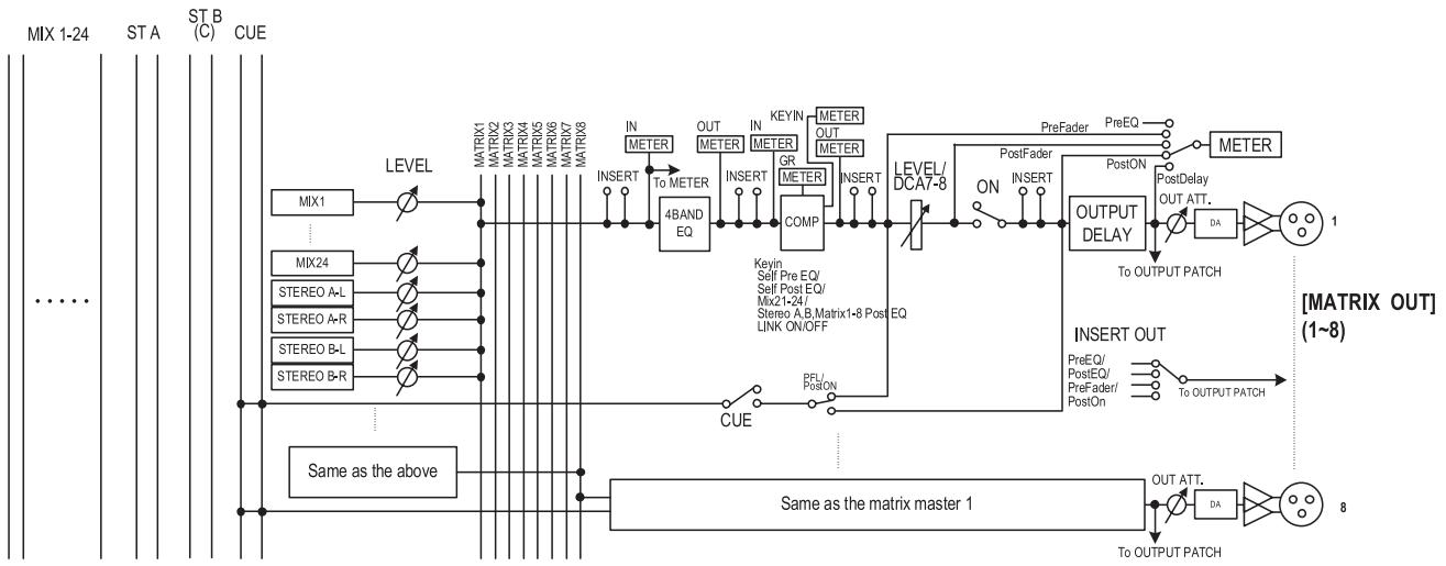
- 8 BAND EQ (8 band equalizer) (MIX channels and STEREO A/B channels)
This is an eight-band (four upper bands + four lower bands) parametric EQ.
- 4 BAND EQ (4 band equalizer) (MATRIX channels)
This is a four-band (HIGH, HIGH MID, LOW MID, LOW) parametric EQ.
COMP (Compressor)
This is a dynamics processor that can be used as a compressor, expander, or limiter.
LEVEL
This adjusts the output level of the channel.
- ON (On/off)
This switches the channel on/off. If this is off, that channel will be muted.
OUTPUT DELAY
This delays the output signal. It can be used to make fine adjustments in the relative timing between channels.
- OUT ATT. (Output attenuator)
This attenuates or boosts the level of the channel's output signal.
METER
This meter indicates the output level of the output channel. The level detection point can be switched.
- MIX to STEREO (MIX channels)
This is an on/off switch for the signal sent from the MIX channel to the STEREO bus.
to MATRIX (MIX channels and STEREO A/B channels)
This is an on/off switch for the signal sent from the MIX channel to the MATRIX bus.
- PAN (MIX channels)
This adjusts the panning of the signal sent from the MIX channel to the STEREO bus.
BAL (Balance) (STEREO channels)
This adjusts the L/R volume balance of the STEREO channel.
- LCR (Left/Center/Right) (MIX channels)
This sends the three-channel signal (left/right channels and a center channel) to the STEREO bus.
- INSERT
Here you can patch the desired output port and input port to insert-out/insert-in, allowing an external effect processor or other device to be inserted. You can switch the insert-out and insert-in locations.
OUTPUT PATCH
Here, output channels can be assigned to output jacks.
Hint
STEREO A/B channels, and MATRIX channels 1-8 are always connected to STEREO OUT jacks A/B, and MATRIX OUT jacks 1-8 respectively. However, you can also make output patch settings to send the signals of these output channels and MIX channels 1-24 to slots 1-4, the 2TR OUT DIGITAL jacks or the MIX OUT jacks.
The MIX section adjusts the send level of the signals sent from input channels to MIX buses, and adjusts the output level of the MIX channels.
Items in the MIX section
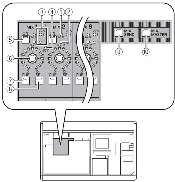
① [TO ST] LED
This LED will light when the signal sent from the MIX channel to the STEREO bus is on.
② [TO MTRX] LED
This LED will light when the signal sent from the MIX channel to the MATRIX bus is on.
③ DCA group LEDs
The LED of the DCA group to which this MIX channel is assigned will light.
(4) MIX [PAIR] LED
This LED will light if adjacent odd-numbered/even-numbered MIX channels are paired.
⑤ MIX [ON] key
If the [MIX SEND] key (⑨) is on, this switches the signal sent from the input channel to the MIX bus on/off. If the [MIX MASTER] key (⑩) is on, this switches the MIX channel on/off.
⑥ MIX encoder
If the [MIX SEND] key (⑨) is on, this adjusts the send level to the MIX bus. If the [MIX MASTER] key (⑩) is on, this adjusts the output level of the MIX channel.
⑦ MIX [CUE] key
This is used to monitor a MIX channel via the Cue Monitor/Solo function.
⑧ MIX [SEL] key
This selects the MIX channel to which operations in the SELECTED CHANNEL section or in the display will apply.
[MITXSEND]key
10 [MIX MASTER] key
These keys switch the operation of the MIX section.
When the [MIX SEND] key is on, you can use the con
trols of the MIX section to edit the send level and on/off status of the signal being sent from the currently selected input channel to the MIX buses. Controls other than ④-⑥ will have no effect.
When the [MIX MASTER] key is on, you can use the controls of the MIX section to edit the output level and on/off status of the MIX channels.
Operations in the MIX section
□ Sending signals from MIX channels to output jacks
Here's how a signal sent from an input channel to a MIX bus can be sent from the corresponding MIX OUT jack.
1 Make sure that an appropriate signal is being sent from an input channel to the MIX bus.
2 Press the [MIX MASTER] key in the MIX section.
When this key is on, you can use the MIX section to control the signals being sent from the MIX channels to the MIX OUT jacks.
3 Turn on the MIX [ON] key for the MIX channel whose signal you want to output.
4 Turn the MIX encoder to adjust the output level of the corresponding MIX channel.
The signal of the corresponding MIX channel will be sent from the corresponding MIX OUT jack.
5 If you want the meters of the panel to indicate the output level of the MIX channels, press the [MIX/MATRIX] key of the meter section.
The output level of the MIX channels will be shown by the [INPUT/MIX] meters.
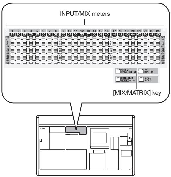
Hint
The detection point (metering point) of the signal levels shown in the meters can be changed if desired. For details, refer to p.109.
- Sending signals from MIX channels to MATRIX buses
Here's how a signal sent from an input channel to a MIX bus can be output to a MATRIX bus. This can be done either by specifying the send level sent from all MIX channels to a specific MATRIX bus, or by specifying the send level sent from a specific MIX channel to all MATRIX buses.
To send signals from all MIX channels to a specific MATRIX bus
1 Make sure that appropriate signals are being sent from input channels to the MIX buses.
2 Repeatedly press the [MATRIX/ST] key of the DISPLAY ACCESS section to access the MATRIX/ST ROUTING screen shown below.
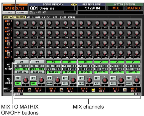
MATRIX/ST ROUTING
3 Use the left/right scroll bar to display the MIX channel that you want to send to the MATRIX bus, and click the MIX TO MATRIX ON/OFF button to turn it on.
The signal of the corresponding MIX channel is now sent to the MATRIX bus.
Hint
You can use the PRE FADER/POST FADER buttons in the MIX TO MATRIX area to change the send point (pre-fader/post-fader) of the signal sent from the MIX channel to the MATRIX bus.
4 Press the [MIX MASTER] key in the MIX section.
5 Press and hold the MATRIX [SEL] key for the send-destination MATRIX bus.
All MIX [SEL] keys will blink. As long as you hold down the MATRIX [SEL] key, the MIX encoders 1-24 will respectively adjust the send levels from the MIX channels to the currently selected MATRIX bus.
6 Continuing to hold down the MATRIX [SEL] key, turn MIX encoders 1-24 to adjust the level of the signal sent from each MIX channel to the currently selected MATRIX bus.
The LEDs around the periphery of the MIX encoder indicate the approximate level. When you take your hand off the MATRIX [SEL] key, the encoders will revert to their previous function.
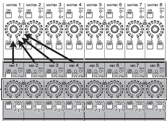
Use the encoders of the MIX section to adjust the send levels
Hint
You can fix the encoders in the above state by rapidly pressing the MATRIX [SEL] key twice. To return to the previous state, press any MIX [SEL] key or MATRIX [SEL] key.
To send from a specific MIX channel to all MATRIX buses
1 Make settings so that a signal is sent from the desired MIX channel to a MATRIX bus, as described in steps 1-3 of "To send signals from all MIX channels to a specific MATRIX bus."
2 Press the [MIX MASTER] key in the MIX section.
3 Press and hold the MIX [SEL] key for the send-source MIX channel.
All MATRIX [SEL] keys will blink. As long as you continue to hold down the MIX [SEL] key, MATRIX encoders 1-8 will adjust the send levels sent from the selected MIX channel to each MATRIX bus.
4 Continuing to hold down the MIX [SEL] key, turn MATRIX encoders 1-8 to adjust the level of the signal sent from the currently selected MIX channel to the MATRIX buses.
The LEDs around the periphery of the MATRIX encoder indicate the approximate send level. When you take your hand off the MIX [SEL] key, the encoders will revert to their previous function.
Use the encoders of the MATRIX section to adjust the send level
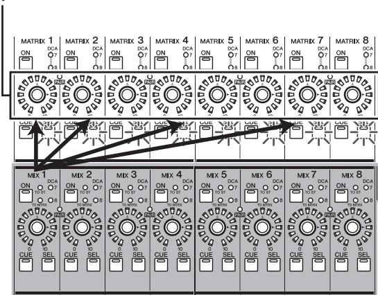
Hint
You can fix the encoders in the above state by rapidly pressing the MIX [SEL] key twice. To return to the previous state, press any MIX [SEL] key or MATRIX [SEL] key.
5 If you want the meters of the panel to indicate the output level of the MIX channels, press the [MIX/MATRiX] key of the meter section.
Hint
The send levels from MIX channels to MATRIX buses can also be edited in the display. For details, refer to p.262.
- Sending signals from MIX channels to the STEREO bus
Here's how signals sent from input channels to MIX buses can be output to the STEREO bus.
1 Make sure that appropriate signals are being sent from input channels to the MIX buses.
2 Press the [MIX MASTER] key in the MIX section.
3 Turn on the MIX [ON] key for the MIX channels whose signals you want to send to the STEREO bus.
4 Press the MIX [SEL] key of the channel whose signal you want to send to the STEREO bus, and turn on the [TO STEREO] key of the SELECTED CHANNEL section.
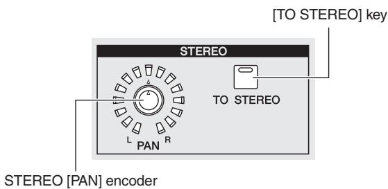
5 To adjust the pan of the signal sent from the MIX channel to the STEREO bus, press the MIX [SEL] key of the desired MIX channel and turn the STEREO [PAN] encoder of the SELECTED CHANNEL section.
6 Turn the MIX encoder to adjust the signal level that is sent to the STEREO bus.
Hint
You can also switch the output to the STEREO bus on/off and adjust the pan from within the MATRIX/ST ROUTING screen (MATRIX/ST function). If desired, the send position (post fader or post ON key) for the signal sent from the MIX channel to the STEREO bus can also be changed in this screen ( p.264) .
7 In the STEREO A/B channel strip, turn the STE-REO A [ON] key and STEREO B [ON] key on (LED lit).
8 In the STEREO A/B channel strip, raise the [STEREO A]/[STEREO B] faders.
The signal sent from the MIX channel to the STEREO bus will be sent from STEREO OUT jacks A/B.
The level of the signal output from the STEREO A/B channels is shown by the [MASTER] meters in the meter section.
Pairing MIX channels
Adjacent odd-numbered/even-numbered MIX channels can be paired. If two MIX channels are paired, their parameters (with the exception of pan and delay) will be linked.
1 Turn on the [MIX MASTER] key in the MIX section.
2 Of the desired two adjacent odd-numbered/ even-numbered MIX channels, hold down the MIX [SEL] key of one, and press the MIX [SEL] key of the other.
The [PAIR] LED will light, and the MIX channels will be paired. At this time, the parameters of the channel whose MIX [SEL] key you pressed first will be copied to the channel whose MIX [SEL] key you pressed later.
For example if you pressed the keys in the order of MIX channel 1 MIX channel 2, the parameters of MIX channel 1 will be copied to MIX channel 2.
3 To defeat pairing, hold down the MIX [SEL] key of one of the paired MIX channels and press the MIX [SEL] key of the other channel.
When MIX channels are paired, the signal flow will change as follows.
Signals sent from an input channel to a VARI type MIX bus
- If the VARI type MIX bus is not paired
When the [MIX SEND] key is on, the MIX encoders will adjust the send level of the signals sent to the corresponding MIX bus from the currently selected input channel.
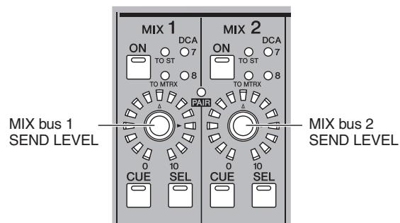
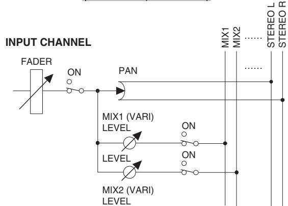
- If the VARI type MIX bus is paired
When the [MIX SEND] key is on, MIX encoders of odd-numbered channels will adjust the pan of the signal sent to the two MIX buses. MIX encoders of even-numbered channels will adjust the shared send level for the two MIX buses.
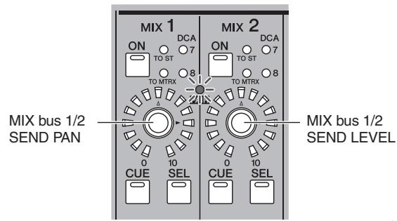
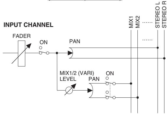
MIX channel output signals
- If MIX channels are not paired
When the [MIX MASTER] key is on, the MIX encoders will adjust the output level of the corresponding MIX channels.
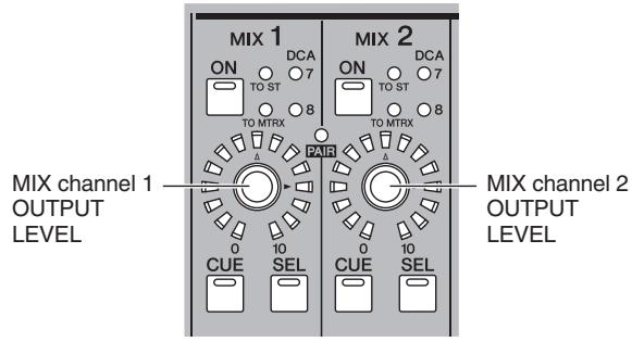
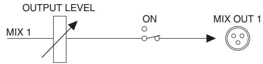
MIX CHANNEL
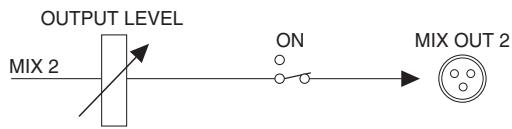
- If MIX channels are paired
When the [MIX MASTER] key is on, the MIX encoders of odd-numbered channels will adjust the volume balance between paired MIX channels. The MIX encoders of even-numbered channels will adjust the shared level of the two paired channels.
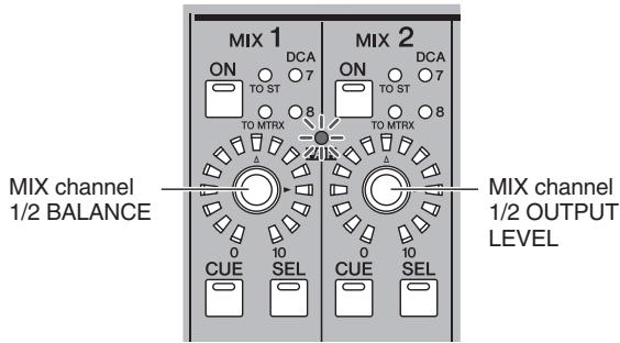
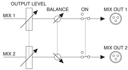
MIX CHANNEL
Hint
MIX channel pairing status and output level/balance settings can also be edited in the CH to MIX screen ( p.299) or MATRIX/ST screen ( p.262).
The STEREO A/B channel strip lets you send the signal of the STEREO A/B channels to the MATRIX bus, and adjust the output level of the STEREO A/B channels.
Items in the STEREO A/B channel strip
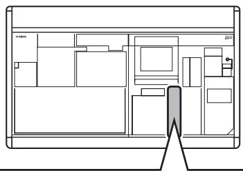
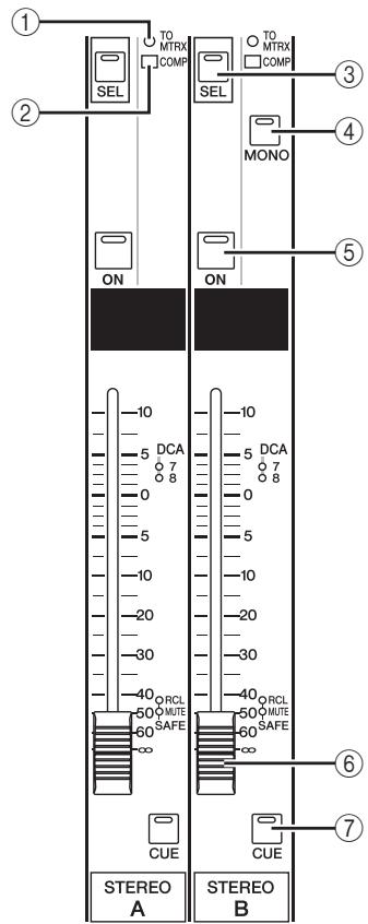
① [TO MATRIX] LED
This LED will light when the signal sent from the STE-REO channel to the MATRIX bus is on.
(2) [COMP] LED
This indicates the operating status of the compressor for the STEREO channel. This will be dark when the gain reduction amount is 0 dB, dimly lit when it is 0-10 dB, and lit when it is greater than 10 dB.
③ STEREO A/B [SEL] key
This selects the STEREO A or STEREO B L/R channels for editing in the SELECTED CHANNEL section or display. The L/R channels will alternate each time you press the key.
④ STEREO [MONO] key
This switches the STEREO B channel to monaural. The status will alternate between monaural and stereo each time you press the key.
⑤ STEREO [ON] key
This switches the STEREO channel on/off. If this key is off (LED dark), no signal will be output from that STEREO channel.
⑥ STEREO fader
This 100mm fader adjusts the output level of the STE-REO channel.
⑦ STEREO [CUE] key
This is used to monitor the STEREO A/B channel via the Cue Monitor/Solo function.
Operations in the STEREO A/B channel strip
□ Sending signals from the STEREO A/B channels to output jacks
Here's how the signals sent from input channels or MIX channels to the STEREO bus can be output from STEREO OUT jacks A/B.
1 Make sure that appropriate signals are being sent from the desired channels to the STEREO bus.
2 Turn on the STEREO [ON] key of the STEREO A/B channel strip.
3 Raise the [STEREO A]/[STEREO B] faders. The signal of the STEREO A/B channels will be output from STEREO OUT jacks A/B. The output level of the STEREO A/B channels is shown by the [MASTER] meters in the meter section.
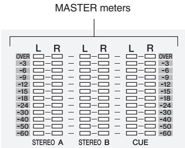
Hint
Normally, the same signal is output from the STEREO A and B channels. However you can also use the STEREO B channel as a Center channel for L/C/R three-channel playback (p.222, 267).
□ Sending signals from the STEREO A/B channels to MATRIX buses
Here's how the signal of the STEREO A/B channels can be sent to the MATRIX buses.
1 Make sure that an appropriate signal is being input to the STEREO bus.
2 Repeatedly press the [MATRIX/ST] key of the DISPLAY ACCESS section to access the MATRIX/ST ROUTING screen.
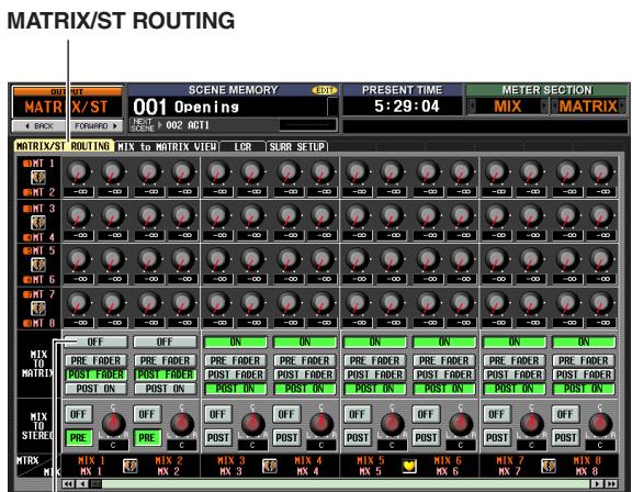
MIX TO MATRIX ON/OFF buttons
3 Use the left/right scroll bar to display the STE-REO A/B channels, and click the MIX TO MATRIX ON/OFF button to turn it on.
With these settings, the signal of the STEREO A/B channels will be sent to the MATRIX channels.
4 Make sure that the STEREO A/B [ON] keys are turned on in the STEREO A/B channel strip; then hold down the STEREO A [SEL] key or STEREO B [SEL] key.
While you continue holding down the key, all MATRIX [SEL] keys will blink. In this condition, you can use the MATRIX encoders to adjust the signal levels sent from the STEREO A or B channel to the MATRIX buses.
5 While continuing to hold down the STEREO A [SEL] key or STEREO B [SEL] key, turn MATRIX encoders 1-8 to adjust the signal level sent to the MATRIX buses.
The LEDs around the periphery of the MATRIX encoder indicate the approximate send level. When you take your hand off the STEREO A [SEL] key or STEREO B [SEL] key, the MATRIX encoders will revert to their previous function.
Hint
- You can also switch to the above state by rapidly pressing the STEREO A [SEL] key or STEREO B [SEL] key twice. To return to the previous state, press any [SEL] key.
- Send levels from the STEREO A/B channels to the MATRIX buses can also be adjusted from within the display ( p.262) .
In the MATRIX section you can adjust the send levels from MIX channels to MATRIX buses, and adjust the output level of the MATRIX channels.
Items in the MATRIX section
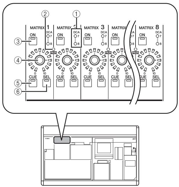
① DCA group LEDs
The LED of the DCA group to which this MATRIX channel is assigned will light.
② MATRIX [PAIR] LED
This LED will light if adjacent odd-numbered/even-numbered MATRIX channels are paired.
③ MATRIX [ON] key
This switches the MATRIX channel on/off.
(4) MATRIX encoder
This adjusts the output level of the MATRIX channel.
⑤ MATRIX [CUE] key
This is used to monitor a MATRIX channel via the Cue Monitor/Solo function.
⑥ MATRIX [SEL] key
This selects the MATRIX channel to which operations in the SELECTED CHANNEL section or in the display will apply.
Operations in the MATRIX section
□ Sending signals from the MATRIX section to output jacks
Here's how the signals sent from MIX channels or STE-REO A/B channels to MATRIX buses can be sent to the MATRIX OUT jacks.
1 Make sure that appropriate signals are being sent from the MIX channels or STEREO A/B channels to the MATRIX buses.
2 In the MATRIX section, press the MATRIX [ON] buttons to turn the desired MATRIX channel(s) on.
3 Turn the encoders of the MATRIX section to adjust the output level of the MATRIX channels.
The signals sent to the MATRIX bus(es) will be sent from the corresponding MATRIX OUT jack(s).
4 To check the output level of the MATRIX channels, press the [MIX/MATRIx] key in the meter section.
The [ST IN/MATRIX] meters will show the output levels.
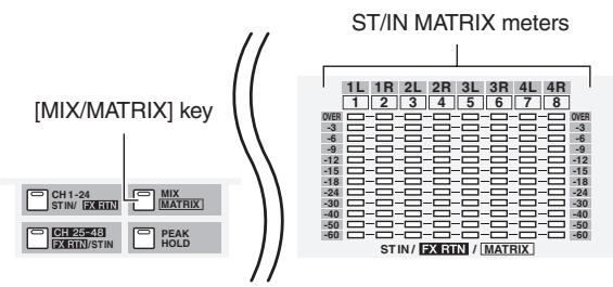
Hint
The detection point (metering point) of the signal levels shown in the meters can be changed if desired ( p.109) .
Pairing the MATRIX section
Adjacent odd-numbered/even-numbered MATRIX channels can be paired if desired. If two channels are paired, their parameters (with the exception of pan and delay) will be linked.
In the MATRIX section, hold down the MATRIX [SEL] key for one of two adjacent odd-numbered/even-numbered channels, and press the MATRIX [SEL] key of the other channel.
The [PAIR] LED will light, and the MATRIX channels will be paired. At this time, the parameters of the channel whose MATRIX [SEL] key you pressed first will be copied to the channel whose MATRIX [SEL] key you pressed later.
For example if you pressed the keys in the order of MATRIX channel 1 MATRIX channel 2, the parameters of MATRIX channel 1 will be copied to MATRIX channel 2.
2 To defeat pairing, hold down the [SEL] key of one of the paired MATRIX channels and press the [SEL] key of the other MATRIX channel.
When MATRIX channels are paired, the signal flow will change as follows.
Signals sent from MIX channels and STE-REO A/B channels to MATRIX buses
- If MATRIX channels are not paired
When you are holding down the [SEL] key of a specific MIX channel or STEREO A/B channel in order to adjust the send levels from that channel to all MATRIX buses, the MATRIX encoders will adjust the send level to the corresponding MATRIX bus.
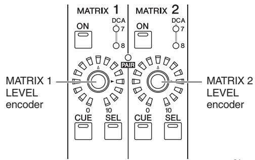
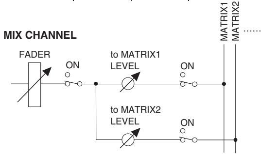
- If MATRIX channels are paired
When you are holding down the [SEL] key of a specific MIX channel or STEREO A/B channel in order to adjust the send levels from that channel to all MATRIX buses, the MATRIX encoder of the odd-numbered channel will adjust the pan of the signal sent to the two MATRIX buses. The MATRIX encoder of the even-numbered channel will adjust the send level shared by the two MATRIX buses.
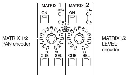
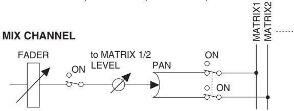
Hint
For details on how to send the signal of a specific MIX channel to all MATRIX buses, refer to p.58. For details on how to send the signal from either the STEREO A or B channel to all MATRIX buses, refer to p.62.
Output signals from MATRIX channels
- If MATRIX channels are not paired
The MATRIX encoders adjust the output level of the corresponding MATRIX channel.
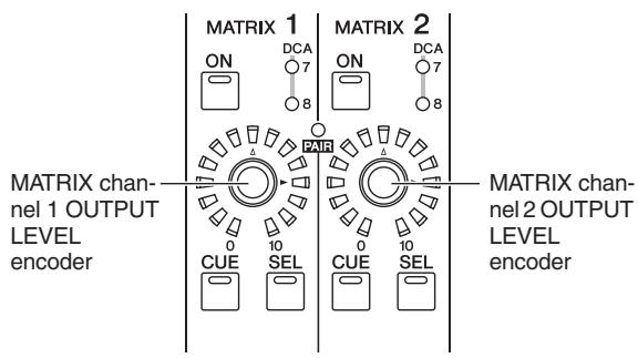
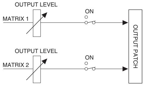
MATRIX CHANNEL
- If MATRIX channels are paired
MIX encoders of odd-numbered channels adjust the volume balance between paired MATRIX channels. MATRIX encoders of even-numbered channels will adjust the shared level of the two paired channels.
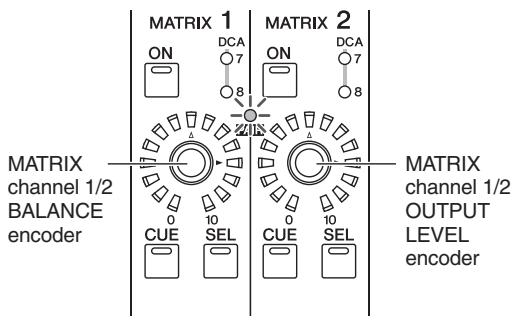
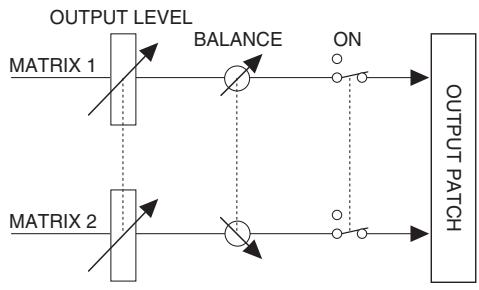
MATRIX CHANNEL
Hint
You can access the MATRIX/ST ROUTING screen (MATRIX/ ST function) to see a list of the MATRIX channels in the display, and edit the pairing and other parameters. For details, refer to p.262 of the Reference section.
7 Using the Selected Channel section
This chapter explains how you can use the SELECTED CHANNEL section to control input channels and output channels.
About the SELECTED CHANNEL section
The SELECTED CHANNEL section lets you edit the mix parameters of the currently selected input channel or output channel; it corresponds to a channel module of a conventional analog mixer.
This section controls the channel that was last selected by pressing its [SEL] key. (In the case of an ST IN channel, FX TRN channel, or STEREO A/B channel, you will select either the L or the R channel.) However, you will be able to edit essentially all of the mix parameters (head amp settings, EQ/compressor/gate settings, output to the STEREO bus, DCA group and mute group assignments, etc.) using panel controls.
Items in the SELECTED CHANNEL section
GROUP
Here you can assign the currently selected channel to DCA groups and mute groups. (For details on DCA groups and mute groups p.82, 83)
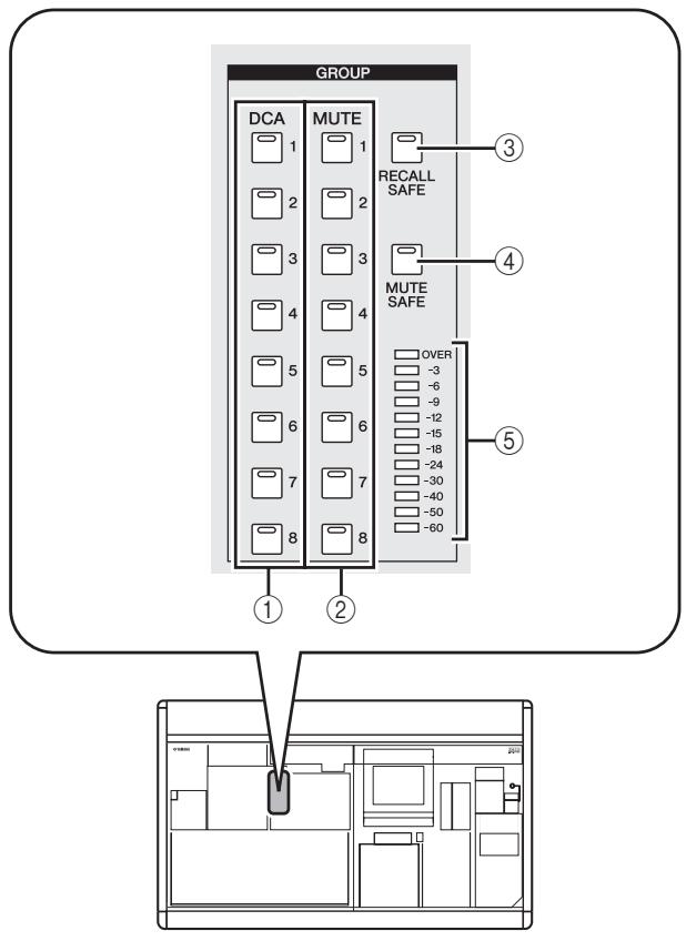
① DCA [1]-[8] keys
These keys assign the selected channel to DCA groups 1-8. The key LED for the assigned DCA group(s) will light.
Input channels can use DCA groups 1-8, and output channels can use DCA groups 7/8. For DCA groups 7/8, input channels and output channels can both exist in the same-numbered group.
② MUTE [1]-[8] keys
These keys assign the selected channel to mute groups 1-8. The key LED for the assigned mute group(s) will light.
Mute groups 1-8 allow you to mix input channels and output channels.
③ [RECALL SAFE] key
This key switches Recall Safe on/off for the selected channel. If this key is on, the parameters of the corresponding channel will not be affected when a scene is recalled. The applicable parameters can be specified in the RECALL SAFE screen (SCENE function)
$$ (\Rightarrow \mathrm {p}. 1 8 2). $$
(4) [MUTE SAFE] key
This key switches Mute Safe on/off for the selected channel. If this key is on, the corresponding channel will be temporarily excluded from mute groups.
(5) Level meter
This indicates the input/output level of the selected channel.
CHANNEL SELECT
Here you can select or copy channels.
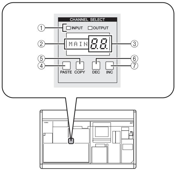
① INPUT/OUTPUT indicators
These indicators show whether an input channel or output channel is selected.
② Name indicator
This indicates the name of the selected channel.
③ Number indicator
This is the number of the selected channel. For stereo channels (ST IN, FX TRN, STEREO A/B), the number and a character of "L" or "r" will appear, depending on whether the L or R channel is selected. If a channel is paired, the decimal point for the lowest place will light. For a FX RTN channel, the LED for the highest place will light.
| Channel | Display |
| ST IN channel | 1L./1r. – 4L./4r. |
| FX RTN channel | 1L./1r. – 4L./4r. |
| STEREO A channel | AL./Ar. |
| STEREO B channel | BL./Br. |
(4) [PASTE] key
(5) [COPY] key
These keys are used to copy and paste channel data. When you press the [COPY] key, the data of the currently selected channel will be copied into a memory buffer; when you press the [PASTE] key, the data in the memory buffer will be pasted into the currently selected channel. You can specify the parameters that will be copied in the INPUT VIEW function CH JOB screen (for input channels) or the OUTPUT VIEW function CH JOB screen (for output channels).
Note
- If the buffer memory contains no data, or if the data in the buffer memory is of a different type than the selected channel, a warning message will appear and the Paste operation cannot be executed.
- The data in the buffer memory is lost when the power is turned off.
⑥ CH [DEC] key
CH [INC] key
The CH [DEC] key decrements the currently selected channel number, and the CH [INC] key increments it.
Input channels 1-48
ST IN channels 1L/1R-4L/4R
FX RTN channels 1L/1R-4L/4R
- MIX channels 1-24
- MATRIX channels 1-8
STEREO A channel L/R
STEREO B channel L/R
DELAY
Here you can edit delay-related parameters for the currently selected channel.
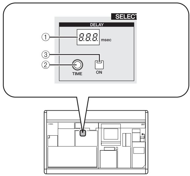
① DELAY [TIME] indicator
This indicates the currently specified delay time in msec units. However in the case of one second, the indicator will be "1...".
② DELAY [TIME] encoder
This controls the delay time of the selected channel.
③ DELAY [ON] key
This key switches delay on/off for the selected channel.
GAIN/ATTENUATION/ ±b (Gain / Attenuation / Phase)
Here you can edit the head amp, post AD conversion attenuator, and phase parameters for the currently selected channel. This section is available only if an input channel is selected.
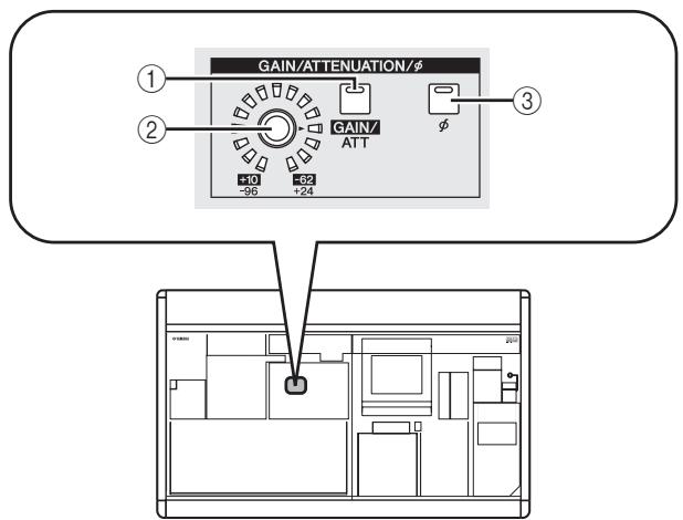
① A[GAIN/ATT] key
This key selects the parameter that is controlled by the [GAIN/ATT] encoder (②).
- [GAIN/ATT] key lit (Gain)
The encoder adjusts the input sensitivity of the internal head amp patched to the input channel (PM5D-RH and DSP5D only) or of an external head amp that supports the dedicated protocol (Yamaha AD8HR, AD824, etc.). The range of adjustment is +10 to -62 .
- [GAIN/ATT] key dark (Attenuator)
The encoder controls the post AD conversion attenuator of the input channel. The range of adjustment is -96 to +24 .
Note
- Gain cannot be selected for channels to which an internal/external head amp is not patched.
- The PAD will be switched on or off internally when the gain of the PM5D-RH internal head amp is adjusted between -14 dB and -13 dB. Keep in mind that noise may be generated if there is a difference between the Hot and Cold output impedance of the external device connected to the INPUT connector/ST IN connector when using phantom power.
- If you don't want it to be possible to select the attenuators, access the UTILITY function PREFERENCE 1 screen, and turn ATT OPERATION ON PANEL off (p.206).
(2) [GAIN/ATT] encoder
According to the setting of the [GAIN/ATT] key (①), this encoder controls either the input sensitivity of the internal/external head amp patched to the input channel, or the attenuator following AD conversion.
The LEDs around the periphery will change as follows.
- [GAIN/ATT] key lit (Gain)
![YAMAHA PM5D-RH - - [GAIN/ATT] key lit (Gain) - 1](/content/2025/01/115055/images/cd59749980eeca3589d06ff2a0fee28dcdcd1300254796b5c8aff7fd1ceb4d9a.jpg)
- [GAIN/ATT] key dark (Attenuator)
![YAMAHA PM5D-RH - - [GAIN/ATT] key lit (Gain) - 2](/content/2025/01/115055/images/c006a7ea87b1bb8e86a6e3a000e297de398e6f39a32de3faa9663dbd206e2cc6.jpg)
③ [0] key
This switches the phase of the selected input channel. If this key is on, the phase will be reversed.
NOISE GATE
Here you can edit noise gate parameters for the selected channel. This section is valid only if an input channel or ST IN channel is selected.
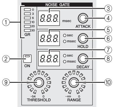
① GATE GR meter
This meter indicates the amount of reduction produced by the gate of the selected channel.
② GATE [ON] key
Switches the gate on/off for the selected channel.
③ GATE [ATTACK] indicator
Indicates the attack time of the gate in msec units.
④ GATE [ATTACK] encoder
Specifies the attack time of the gate (the time from when the signal exceeds the threshold until the gate opens).
⑤ GATE [HOLD] indicator
Indicates the hold time of the gate in msec units or sec units (the indicator for the displayed unit will light).
⑥ GATE [HOLD] encoder
Specifies the hold time of the gate (the time from when the signal falls below the threshold until the gate closes).
⑦ GATE [DECAY] indicator
Indicates the decay time of the gate in msec units or sec units.
GATE [DECAY] encoder
Specifies the hold time of the gate (the time over which the gate will close after the hold time has elapsed).
GATE [THRESHOLD] encoder
Specifies the threshold level of the gate (the level at which the gate will open or close). The gate will open when the signal exceeds this level, and will close when the signal falls below this level.
GATE [RANGE] encoder
Specifies the amount of attenuation while the gate is closed.
STEREO
Here you can switch the on/off status of the signal sent from the selected channel to the STEREO bus, and adjust the pan.
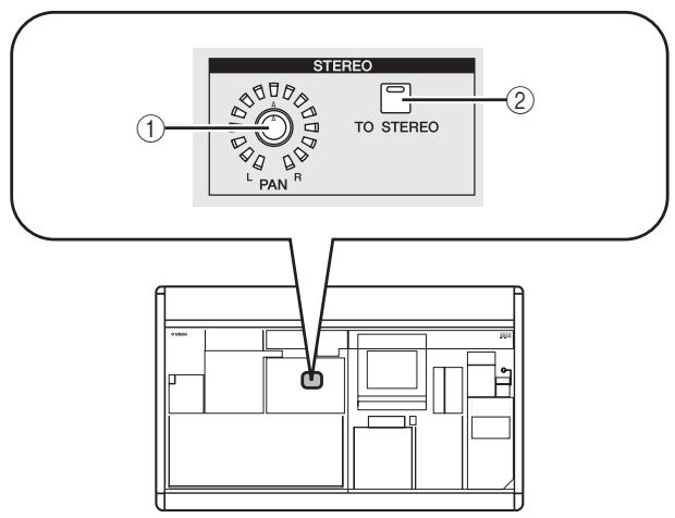
① STEREO [PAN] encoder
The function of this encoder depends on the currently selected channel, as follows.
| Selected channel | Function |
| Input channel | Adjusts the panning of the signal sent from that channel to the STE-REO bus. |
| ST IN channel | |
| FX RTN channel | |
| MIX channel | |
| STEREO A/B channels | Adjusts the left/right balance of the signal sent from the STEREO A/B channels. |
| MATRIX channel | No function. |
② [TO STEREO] key
The function of this key depends on the currently selected channel, as follows.
| Selected channel | Function |
| Input channel | Functions as an on/off switch for the signal sent from that channel to the STEREO bus. |
| ST IN channel | |
| FX RTN channel | |
| MIX channel | |
| STEREO A/B channels | No function. |
| MATRIX channel |
COMPRESSOR
Here you can edit compressor parameters for the selected channel. This section is available only if a channel other than an FX RTN channel is selected.
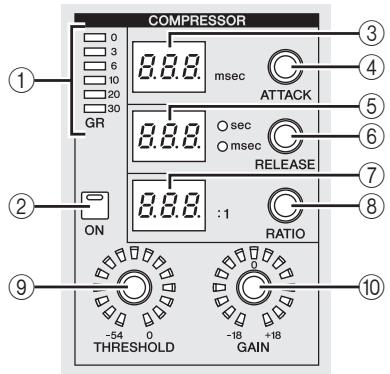
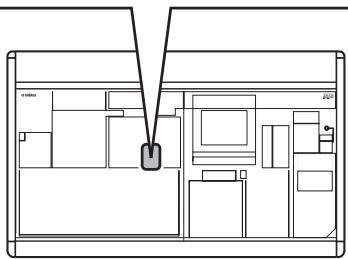
① COMP GR meter
This meter indicates the amount of reduction produced by the compressor of the selected channel.
② COMP [ON] key
Switches the compressor on/off for the selected channel.
③ COMP [ATTACK] indicator
Indicates the attack time of the compressor in msec units.
④ COMP [ATTACK] encoder
Specifies the attack time of the compressor (the time from when the signal exceeds the threshold level until compression begins).
⑤ COMP [RELEASE] indicator
Indicates the release time of the compressor in msec units or sec units (the indicator for the displayed unit will light).
⑥ COMP [RELEASE] encoder
Specifies the release time of the compressor (the time from when the signal falls below the threshold level until compression is removed).
⑦ COMP [RATIO] indicator
Indicates the compression ratio setting.
COMP [RATIO] encoder
Specifies the compression ratio (the ratio at which the input signal will be compressed when the signal exceeds the threshold level).
COMP [THRESHOLD] encoder
Specifies the threshold level of the compressor (the level at which the compressor will operate). The input signal will start being compressed when the signal exceeds this level; compression will be removed when the signal falls below this level.
10 COMP [GAIN] encoder
Specifies the gain of the signal that has passed through the compressor.
HPF (High Pass Filter)
Here you can edit high pass filter parameters for the selected channel. This section is available only if an input channel is selected.
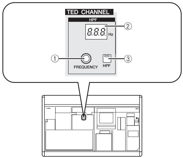
① HPF [FREQUENCY] encoder
Specifies the cutoff frequency of the high pass filter.
② HPF [FREQUENCY] indicator
Indicates the currently specified high pass filter cutoff frequency, in units of Hz.
③ HPF [ON] key
Switches the high pass filter on/off.
EQUALIZER
Here you can edit equalizer parameters for the selected channel. The equalizer structure differs as follows between input channels and output channels.
Input channels
You can use a four-band peak/dip type EQ (HIGH, HIGH MID, LOW MID, LOW). The HIGH band can be switched to an LPF or shelving type; the LOW band can be switched to a shelving type.
Output channels
If a MIX channel or STEREO A/B is selected, you can use an eight-band peak/dip type EQ. (Operation is divided into UPPER and LOWER groups of four bands each.) For MATRIX channels, you can use a four-band peak/dip type EQ.
For any output channel, the HIGH band can be switched to shelving or LPF. The LOW band can be switched to shelving or HPF. For MIX channels and STEREO A/B channels, this can be specified for UPPER and LOWER, allowing you to apply shelving or filtering twice.
Hint
- Input channels also provide an HPF that is independent of the four-band EQ.
Output channels do not have an independent HPF, but instead allow you to switch the LOW band type to HPF. - Switching the equalizer type to HPF or LPF can be done in the EQ PARAM screen (⇒ p.250)
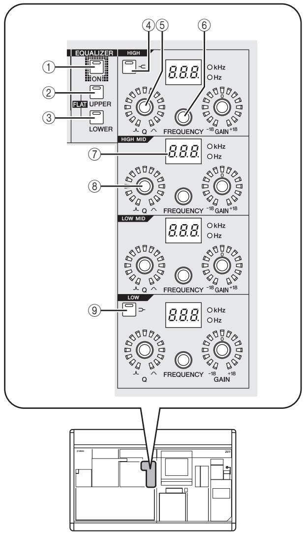
① EQ [ON] key
Switches the equalizer on/off for the selected channel.
② EQ [UPPER] key
③ EQ [LOWER] key
If a MIX channel or STEREO A/B channel is selected, these keys select the four-band group (UPPER or LOWER) that you will edit. (The LED of the currently selected key will light.)
If any other channel is selected, the LEDs of both keys will be dark.
Hint
By simultaneously holding down the EQ [UPPER] key and EQ [LOWER] key, you can return the EQ GAIN settings of the selected channel to a flat state.
④ EQ [−C] key
If this key is on, the corresponding HIGH band EQ type will be switched to shelving. In this case, the HIGH band EQ [Q] knob will have no function.
⑤ EQ [Q] encoder
Adjusts the Q (steepness) of each band. This encoder does nothing for bands whose EQ type is set to shelving, LPF, or HPF.
⑥ EQ [FREQUENCY] encoder
Adjusts the center frequency (or cutoff frequency) at which each band will be boosted or cut.
⑦ EQ [FREQUENCY] indicator
Indicates the center frequency (or cutoff frequency) at which boost/cut will occur, in units of kHz or Hz. (The indicator for the displayed unit will light.)
⑧ EQ [GAIN] encoder
Adjusts the amount of cut/boost for each band.
⑨ [D-] key
If this key is on, the corresponding LOW band EQ will be switched to shelving type. In this case, the LOW band EQ [Q] knob will have no function.
Operations in the SELECTED CHANNEL section
Selecting a channel and editing its parameters
The SELECTED CHANNEL section always controls the channel that was last selected by its [SEL] key.
To select an input channel, press a [SEL] key in the INPUT channel strip or ST IN/FX RTN channel strip. (If necessary, switch the layer before pressing a [SEL] key.) To select an output channel, press a [SEL] key in the MIX section, MATRIX section, or STEREO A/B channel strip.
1 Press a [SEL] key to select the channel you want to control.
The number and name of the currently selected channel is shown in the SELECTED CH area at the lower left of the display, and by the name indicator and number indicator in the SELECTED CHANNEL section.
Note
If the console is cascade-connected to the DSP5D, the MACHINE ID field will show the machine ID number.
Number of the selected channel
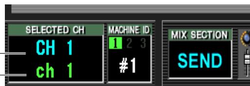
Name of the selected channel
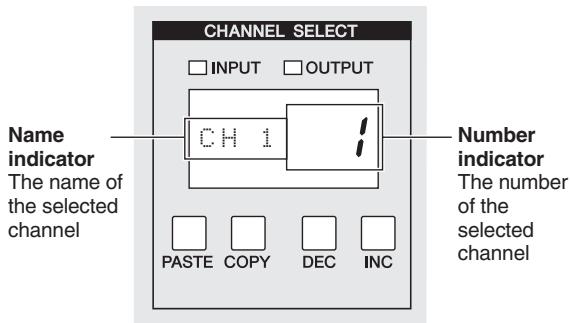
The number shown in the number indicator is as follows. If a channel is paired, the decimal point for the lowest place will light. For a FX RTN channel, the decimal point for the highest place will light.
| Selected channel | Number indicator |
| Input channels 1–48 | 1–48 |
| ST IN/FX RTN channels 1–4 (L/R) | 1L./1r. – 4L./4r. |
| MIX channels 1–24 | 1–24 |
| MATRIX channels 1–8 | 1–8 |
| STEREO A/B channels (L/R) | AL., Ar., BL., Br. |
Hint
- In the case of stereo channels (ST IN/FX RTN channels, STEREO A/B channels), you can switch between L/R by pressing the same [SEL] key.
- You can also switch the channel by using the CH [DEC] key / CH [INC] key of the SELECTED CHANNEL section.
2 Use the controls of the SELECTED CHANNEL section to edit the parameters of the selected channel.
When you select a channel in step 1, the parameter values of that channel will be shown by the LEDs and indicators of the SELECTED CHANNEL section. These parameters can be edited using the controls of the SELECTED CHANNEL section.
Hint
- Gate, compressor, and EQ/HPF operations are explained in the second half of this chapter; refer to the appropriate section for details.
- For details on DCA group and mute group operations, refer to p.82, 83.
- If you operate a parameter that is selected for AUTO DISPLAY in the PREFERENCE 1 screen, the screen associated with that parameter will appear automatically.
3 In the same way, select other channels and edit their parameters.
Compressor operations
Here's how you can use the SELECTED CHANNEL section to operate the internal compressor.
Note
The PM5D provides four types of built-in compressor; COMP (compressor), EXPANDER (expander), COMPANDER H (hard compander), and COMPANDER S (soft compander). These four operate in different ways. This means that if you want to use a compressor, you must load compressor settings of the desired type from the compressor library, and then edit the parameters as desired.
1 Press a [SEL] key to select the channel you want to control.
A compressor is available for all channels except for FX RTN channels.
2 In the DISPLAY ACCESS section, press the INPUT [GATE/COMP] key (for an input channel) or OUTPUT [COMP] key (for an output channel) several times to access the COMP LIBRARY screen.
![YAMAHA PM5D-RH - In the DISPLAY ACCESS section, press the INPUT [GATE/COMP] key (for an input channel) or OUTPUT [COMP] key (for an output channel) several times to access the COMP LIBRARY screen. - 1](/content/2025/01/115055/images/7c2b4d3ed9ca9ed4ed6d1fa918b0106061a822173da51fa5ae000f854ef9b9bd.jpg)
In the COMP LIBRARY screen you can store compressor settings in the library, or recall existing data from the library. The operations described below are the same for the COMP LIBRARY screen of both output channels and input channels.
3 Move the cursor to the scroll bar of the library list in the lower right of the screen, and turn the [DATA] encoder to select the library item that you want to load. (The library item selected in the list is highlighted.)
Numbers 001-036 for which an "R" is shown at the right of the list contain read-only preset library items. Numbers 001-004 contain preset library items of different types. It is convenient to use these library items when you want to select a specific type. Preset library items 001-004 are respectively of the following types.
| Number | Name | Type |
| 001 | Comp | COMP (Compressor) |
| 002 | Expand | EXPANDER |
| 003 | Compander (H) | COMPANDER H (Hard com-pander) |
| 004 | Compander (S) | COMPANDER S (Soft com-pander) |
Hint
- The type of the currently selected compressor is shown in the COMP PARAM screen ( p.253, 291).
- The COMP LIBRARY screen also provides other library settings suitable for a wide variety of instruments or purposes. Settings you edit can also be stored in the library.
- For a detailed explanation of each type of compressor, refer to the Appendices (p.322).
4 After selecting a library item, click the RECALL button located at the lower left of the library list.
The library item you selected in step 3 will be recalled to the channel you selected in step 1.
5 In the SELECTED CHANNEL section, press the COMP [ON] key to make the LED light.
The compressor of the selected channel will be activated.
![YAMAHA PM5D-RH - In the SELECTED CHANNEL section, press the COMP [ON] key to make the LED light. - 1](/content/2025/01/115055/images/c0e7198b82be18c48af0614353c21ec9e85018b5f9c27c191ccae67b957da8a9.jpg)
6 You can use the compressor controls of the SELECTED CHANNEL section to edit the compressor parameters.
The amount of gain reduction produced by the compressor is shown by the COMP GR meter in the SELECTED CHANNEL section.
Hint
- For details on the function of the compressor controls, refer to p.68.
- More detailed parameters for the compressor (selection of the key-in signal, stereo link on/off, assignment to a compressor link group) can be edited in the COMP PARAM screen of the INPUT GATE/COMP function or the OUTPUT COMP function ( p.253, 291) .
- You can also cause the COMP PARAM screen to appear automatically when you operate a compressor-related control. This setting is made in the UTILITY function PREFERENCE 1 screen ( p.204).
Gate operations
Here's how you can use the SELECTED CHANNEL section to operate the internal gate.
Note
The PM5D provides two types of built-in gating; GATE and DUCKING. These operate in different ways. This means that if you want to use a gate, you must load gate settings of the desired type from the gate library, and then edit the parameters as desired.
1 Press a [SEL] key to select the channel you want to control.
Gate is available only for input channels or ST IN channels.
2 In the DISPLAY ACCESS section, press the INPUT [GATE/COMP] key several times to access the GATE LIBRARY screen.
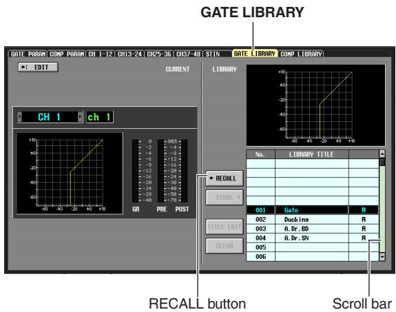
In the GATE LIBRARY screen you can store gate settings in the library, or recall existing data from the library.
3 Move the cursor to the scroll bar of the library list in the lower right of the screen, and turn the [DATA] encoder to select the library item that you want to load. (The library item selected in the list is highlighted.)
Numbers 001-004 for which an "R" is shown at the right of the list contain read-only preset library items. Numbers 001-002 contain preset library items of different types. It is convenient to use these library items when you want to select a specific type. These numbers correspond to the different types as follows.
| Number | Name | Type |
| 001 | Gate | GATE |
| 002 | Ducking | DUCKING |
Hint
- The type of the currently selected gate is shown in the GATE PARAM screen (p.289).
- The GATE LIBRARY screen also provides other library settings suitable for a wide variety of instruments or purposes. You can also save your own settings in the library.
- For a detailed explanation of each type of gate, refer to the Appendices (→ p.321).
4 After selecting a library item, click the RECALL button located at the lower left of the library list.
The library item you selected in step 3 will be recalled to the channel you selected in step 1.
5 In the SELECTED CHANNEL section, press the GATE [ON] key to make the LED light.
The gate of the selected channel will be activated.
6 You can use the gate controls of the SELECTED CHANNEL section to edit the gate parameters.
The amount of gain reduction produced by the gate is shown by the GATE GR meter in the SELECTED CHANNEL section.
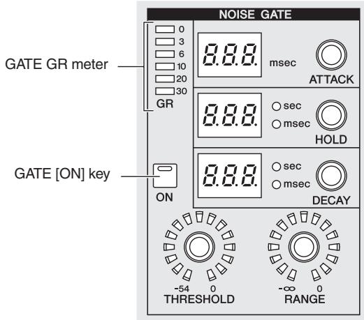
Note
The THRESHOLD LED will not light if the threshold level is between -55dB and -72dB .
Hint
- For details on the function of the gate controls, refer to p.67.
- More detailed parameters for the gate (selection of key-in signal, stereo link on/off) can be edited in the INPUT GATE/COMP function GATE PARAM screen ( p.289) .
- You can also cause the GATE PARAM screen to appear automatically when you operate a gate control. This setting is made in the UTILITY function PREFERENCE 1 screen ( p.204) .
EQ/HPF operations
Here's how you can use the SELECTED CHANNEL section to edit the EQ (equalizer) and HPF (High Pass Filter). EQ can be used on all input channels and all output channels. An HPF that is independent of the EQ is provided only for input channels. However even on output channels, you can switch the LOW band type to HPF.
1 Press a [SEL] key to select the channel you want to control.
Four-band EQ (HIGH, HIGH MID, LOW MID, LOW) is provided on all input channels and on MATRIX channels.
Eight-band EQ is provided on MIX channels and STE-REO A/B channels. (Control is divided into UPPER and LOWER sections of four bands each.)
2 In the SELECTED CHANNEL section, make sure that the EQ [ON] key is on.
If you selected a MIX channel or STEREO A/B channel in step 1, use the SELECTED CHANNEL section EQ [UPPER] key or EQ
[LOWER] key to select the UPPER or LOWER group of four bands.
![YAMAHA PM5D-RH - In the SELECTED CHANNEL section, make sure that the EQ [ON] key is on. - 1](/content/2025/01/115055/images/54b92a8f03696276231bff01100f03807229b80f87d5265a7af9ef33d49e8ca4.jpg)
3 For each band, use the EQ [Q] encoder, EQ [FREQUENCY] encoder, and [GAIN] encoder to edit the steepness, center frequency, and gain respectively.
![YAMAHA PM5D-RH - In the SELECTED CHANNEL section, make sure that the EQ [ON] key is on. - 2](/content/2025/01/115055/images/5c8be37cf8aa5aa103b466f201b49a97e261acda88ec937111f22fe009106c1c.jpg)
Hint
If the input signal of an input channel clips because of EQ boost, make the SELECTED CHANNEL section [GAIN/ATT] key go dark and use the [GAIN/ATT] encoder to lower the level.
4 If you want to restore the EQ of the currently operated channel to a flat state, simultaneously hold down the EQ [UPPER] and EQ [LOWER] keys of the SELECTED CHANNEL section.
When you hold down these two keys simultaneously, the boost/cut amount of all bands will be reset to 0 dB.
5 If you want to use the HIGH band or LOW band as a shelving-type EQ, turn on the [-C] key or [> -] key for the corresponding band.
6 If you want to use HPF on an input channel, turn on the HPF [ON] key in the SELECTED CHANNEL section.
Input channels provide an HPF that is independent of the four-band EQ. Use the HPF [ON] key to switch the HPF on/off, and use the HPF [FREQUENCY] encoder to specify the cutoff frequency.
![YAMAHA PM5D-RH - If you want to use HPF on an input channel, turn on the HPF [ON] key in the SELECTED CHANNEL section. - 1](/content/2025/01/115055/images/3ca9c1190c9a042204310355b192835f7fc2d0821046246f74dd52314d12b876.jpg)
Hint
- Output channels do not provide an HPF that is independent of the EQ, but you can switch the LOW band type to HPF, or the HIGH band type to LPF. This change is made in the OUTPUT EQ function EQ PARAM screen (p.250).
- For input channels you can switch the HIGH band type to LPF. This change is made in the INPUT /EQ function EQ PARAM screen (p.286).
Hint
- You can cause the associated screen to appear automatically when you operate equalizer or HPF parameters in the SELECTED CHANNEL section. This setting is made in the UTILITY function PREFERENCE 1 screen ( p.204).
- In the same way as for compressor or noise gate settings, EQ settings can also be stored to or recalled from a dedicated EQ library. Preset library items suitable for a variety of instruments or situations are also provided.
8 Input Patch / Output Patch operations
This chapter explains how to edit the input patch and output patch settings, and how to use insert connections and direct output.
Changing the input patch settings
The input patch section lets you assign input ports to input channels. In the PM5D's default state, the input patch settings assign the following signals to input channels.
| Input channels 1–48 | Input signals from INPUT jacks 1–48 |
| ST IN channels 1–4 | Input signals from ST IN jacks 1–4 (L/R) |
| FX RTN channels 1–4 | Output signals of internal effects 1–4 (L/R) |
However, you will need to edit the input patch settings if you want input signals from an I/O card installed in slots 1-4 or input signals from a 2TR IN DIGITAL jack to be assigned to an input channel. Here's how to do this.
1 In the DISPLAY ACCESS section, press the INPUT [PATCH] key several times to access the INPUT PATCH screen.
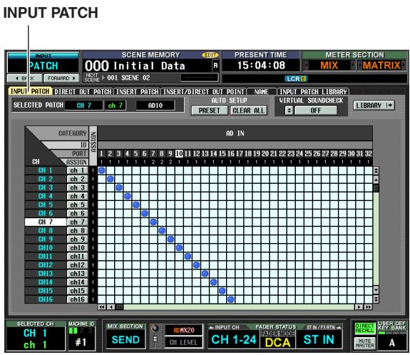
The INPUT PATCH screen is where you can patch (assign) input ports (rear panel input jacks or input channels of I/O cards) to input channels.
The horizontal direction of the screen shows the input ports (i.e., patch sources), and the vertical direction of the screen shows the input channels (i.e., patch destinations).
If an input port is patched to an input channel, a symbol is displayed at the intersecting grid.
2 Use the left/right scroll bar to display the patch-source input port.
The horizontal direction of the screen shows the patch source's input port type, ID number, port number, and the number of input channels that are assigned to it. To view input ports that are not currently visible, use the horizontal scroll bar or the [DATA] encoder.
From the top, this shows the input port type and ID number, the port number, and the number of input channels currently assigned.
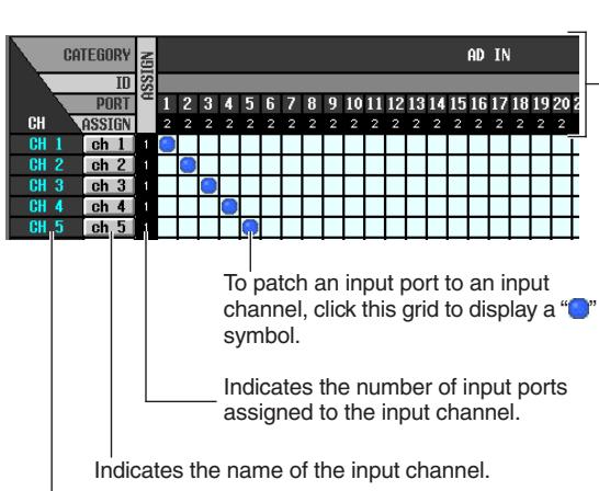
Indicates the number of the input channel.
You can select the following input ports.
| AD IN 1–48 | INPUT jacks 1–48 |
| AD ST IN 1–4 | ST IN jacks 1–4 (L/R) |
| SLOT IN 1–4 | Input channels (1–16) of slots 1–4 |
| FX OUT 1–8 | Outputs (L/R) of internal effects 1–8 |
| 2TR IN D1–D3 | 2TR IN DIGITAL jacks 1–3 (L/R) |
| 2TR IN A1/A2 | 2TR IN ANALOG jacks 1/2 |
3 Use the vertical scroll bar to display the patch-destination input channel.
The vertical direction of the screen shows the patch-destination input channels. To see channels that are not currently visible, use the vertical scroll bar. Alternatively, you can hold down the [SHIFT] key and turn the [DATA] encoder.
The following input channels can be selected.
| CH 1–48 | Input channels 1–48 |
| STIN1L/1R-STIN4L/4R | ST IN channels 1–4 (L/R) |
| FXRTN1L/1R-FXRTN4L/4R | FX RTN channels 1–4 (L/R) |
4 Click the grid where the desired patch-source and patch-destination intersect.
The vertical and horizontal red lines indicate the grid position where the cursor is located. The SELECTED PATCH area in the upper left of the screen shows the input port and input channel for the grid at which the cursor is located.
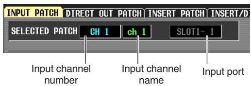
When you click a grid, a window will ask you to confirm that you want to change the patch setting.
5 Click the OK button in the window.
The new patch will be finalized, and a “ ” symbol will appear at the corresponding grid.
To cancel the patch, click the " " symbol once again.
Hint
- If you want to change the patch directly without having to respond to the confirmation window, go to the UTILITY function PREFERENCE 1 screen and turn PATCH CONFIRMATION off (p.204).
To move the cursor location rapidly in or out of the grid, hold down the [SHIFT] key and press the CURSOR [][]/[] /[▼] keys.
Note
You can patch a single input port to multiple input channels, but you cannot patch multiple input ports to a single input channel.
Changing the output patch settings
In the output patch section you can assign output channels to output ports. When the PM5D is in its initial state, MIX channels 1-24 are assigned to MIX OUT jacks 1-24. Other output channels are always connected to the following output jacks.
| MIX channels 1–24 | MIX OUT jacks 1–24 |
| STEREO A/B channels | STEREO OUT jacks A/B |
| MATRIX channels 1–8 | MATRIX OUT jacks 1–8 |
| Monitor output L/R/C | MONITOR OUT jacks L/R/C |
However you can edit the output patch settings so that the signals of these output channels are also sent from other output ports in parallel. Here's how to do this.
1 In the DISPLAY ACCESS section, press the OUTPUT [PATCH] key several times to access the OUTPUT PATCH screen.
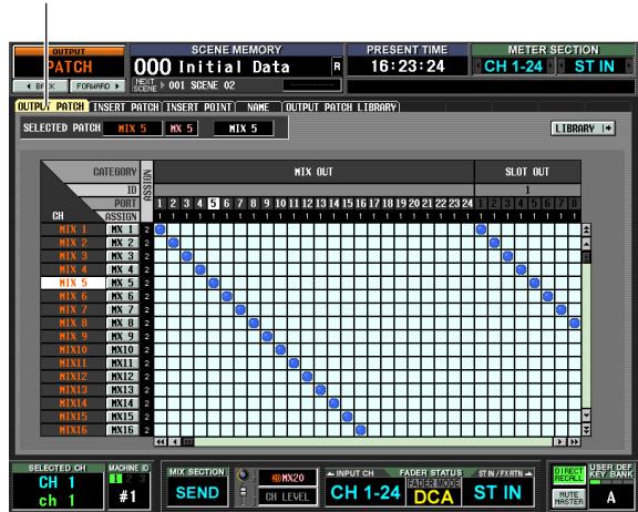
OUTPUT PATCH
In the OUTPUT PATCH screen you can patch (assign) output channels to output ports. The horizontal direction of the screen shows the output ports (i.e., patch destinations), and the vertical direction of the screen shows the output channels (i.e., patch sources).
When the PM5D is in its default state, MIX channels 1-24, MATRIX channels 1-8, and the STEREO A channel are patched to the output channels of slots 1-4 and the 2TR OUT DIGITAL jacks in addition to the
output jacks that are always connected. However, you are free to change this patching.
2 Use the horizontal scroll bar to display the patch-destination output port.
The horizontal direction of the screen shows the patch destination's output port type, ID number, port number, and the number of output channels that are assigned to it.
From the top, this area shows the output port type, ID number, port number, and number of assigned output channels.
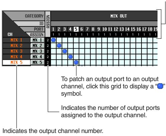
You can select the following output ports.
| MIX OUT | MIX OUT jacks 1–24 |
| SLOT OUT 1–4 | Output channels (1–16) of an I/O card installed in slots 1–4 |
| FX IN 1–8 | Inputs (L/R) of internal effects 1–8 |
| 2TR OUT D1/D2 | 2TR OUT DIGITAL jacks 1–2 (L/R) |
3 Use the vertical scroll bar to display the patch-source output channel.
The vertical direction of the screen shows the patch-source output channels.
The following output channels can be selected.
| MIX 1-24 | MIX channels 1-24 |
| MATRIX 1-8 | MATRIX channels 1-8 |
| ST AL/AR | STEREO A channel (L/R) |
| ST BL/BR | STEREO B channel (L/R) |
| MONITOR L/R/C (PM5D) | Monitor output (L/C/R) |
| CUE L/R (DSP5D) | Cue output (L/R) |
| TALKBACK OUT | Talkback output |
| OSC OUT | Oscillator output |
Note
For the PM5D, the CUE L/R channels are unavailable; for the DSP5D, the MONITOR L/R/C channels are unavailable.
4 Click the grid where the desired patch-source and patch-destination intersect.
The SELECTED PATCH area in the upper left of the screen shows the output port and output channel for the grid at which the cursor is located.
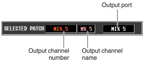
When you click a grid, a window will ask you to confirm that you want to change the patch setting.
Hint
If you want to change the patch directly without having to respond to the confirmation window, go to the UTILITY function PREFERENCE 1 screen and turn PATCH CONFIRMATION off (p.204).
5 Click the OK button in the window.
The new patch will be finalized, and a " " symbol will appear at the corresponding grid. To cancel the patch, click the " " symbol once again.
Note
You can patch an output channel to more than one output port, but you cannot patch multiple output channels to a single output port.
You can insert an effect processor or other external device into the signal route of an input channel or output channel. When doing so, you can specify for each channel the input/output port and insert I/O point that you want to use for insertion.
Connecting an external device for insertion
When inserting an external device into a desired channel, you can use the rear panel input/output jacks or the input/ output jacks of an I/O card installed in a slot as insert-out/ insert-in jacks.
The following diagrams show typical examples of insert connections.
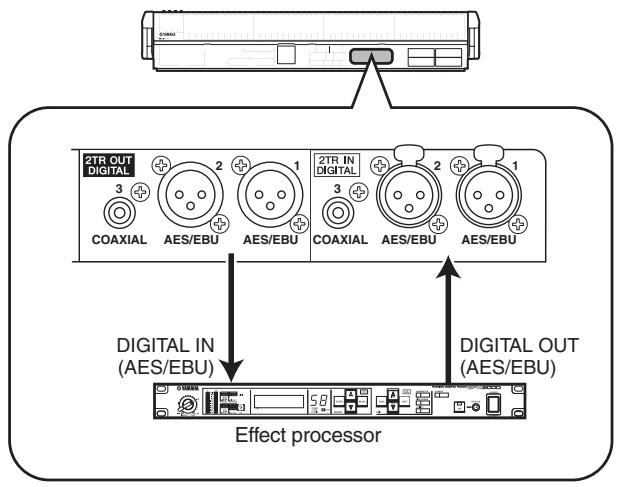
Insert connection example ①
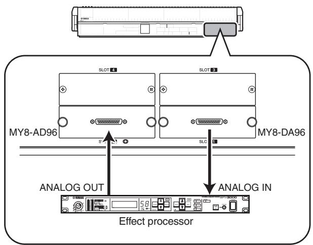
Insert connection example ②
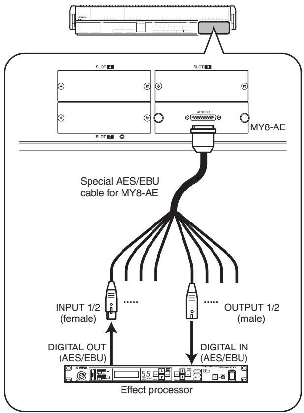
Insert connection example ③
If you are inserting an external digital device via a digital I/O card as shown in "Insert connection example ③," you will need to synchronize the word clock of the PM5D and the external device. Normally, we recommend that you set the external device as a word clock slave, and make it follow the PM5D's word clock. (For details on how to set your device as a word clock slave, refer to its manual.)
Hint
For the PM5D model, you can also use the rear panel INSERT IN/OUT jacks to insert an external device into an input signal, as an alternative to the method described above. In this case, the insert I/O point is fixed at immediately before AD conversion. Also, the steps described p.78 will not be necessary.
Patching the insert-out and insert-in
Here we will explain how to make insert connections, using an example in which an external device connected to an AD/DA card in a slot is inserted into an input channel. However, the procedure is the same when inserting into an output channel, the only difference being that you will be working in a screen for output channels.
1 In the DISPLAY ACCESS section, press the INPUT [PATCH] key several times to access the INSERT PATCH screen (INPUT PATCH function) shown below.
In the left side of this screen you can select an output port to use as insert-out, and in the right side of the screen you can select an input port to use as insert-in.
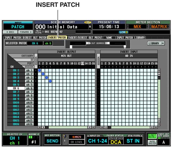
If you want to insert into an output channel, press the OUTPUT [PATCH] key several times to access the OUTPUT PATCH function INSERT PATCH screen.
2 In the left side of the screen, click the grid at which the output port connected to your external device intersects the desired channel.
The procedure is the same as in the INPUT PATCH screen or OUTPUT PATCH screen. You can select the following output ports.
| MIX OUT 1-24 | MIX OUT jacks 1-24 |
| SLOT OUT 1-4 | Output channels of an I/O card installed in slots 1-4 |
| FX IN 1-8 | L/R inputs of internal effects 1-8 |
| GEQ IN 1-12 | Inputs of GEQ modules 1-12 |
| 2TR OUT 1-3 | 2TR OUT DIGITAL jacks 1-3 (L/R) |
Hint
If you select GEQ IN at the left side of the screen, the identically-numbered GEQ OUT will be automatically selected at the right side of the screen, inserting the correspondingly-numbered GEQ module into that channel. (For details on using the graphic EQ p.118 )
3 In the right side of the screen, click the grid at which the input port connected to your external device intersects the desired channel.
You can select the following input ports.
| AD IN 1-48 | INPUT jacks 1-48 |
| AD ST IN 1-4 | ST IN jacks 1-4 (L/R) |
| SLOT IN 1-4 | Input channels of an I/O card installed in slots 1-4 |
| FX OUT 1-8 | Outputs (L/R) of internal effects 1-8 |
| GEQ OUT 1-12 | Outputs of GEQ modules 1-12 |
| 2TR IN D1-D3 | 2TR IN DIGITAL jacks 1-3 (L/R) |
| 2TR IN A1/A2 | 2TR IN ANALOG jacks 1/2 (L/R) |
The SELECTED PATCH area shows the channel corresponding to the grid at which the cursor is located. To the right of this are shown the input/output ports patched to insert-out/insert-in for this channel.
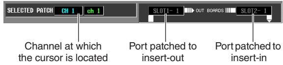
Hint
To move the cursor rapidly between the grids in the left and right sides of the screen, you can hold down the [SHIFT] key and press the CURSOR []/[] keys.
Note
With the steps you have taken so far, the external device has been patched to the insert-out/insert-in of the selected channel. However, please note that the insert connection is not actually enabled until you turn on the INSERT I/O ON/OFF button in the INSERT/DIRECT OUT screen as described below. As an exception to this, the INSERT I/O ON/OFF button is automatically turned on if you patch a GEQ.
4 Press the INPUT [PATCH] key several times to access the INSERT/DIRECT OUT POINT screen (INPUT PATCH function) shown below.
In the INSERT/DIRECT OUT POINT screen (INPUT PATCH function) you can switch insert on/off for each input channel. In this screen you can also select the insert I/O point (the location at which the external device will be inserted).
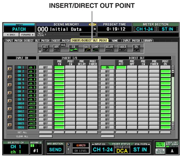
If you want to insert into an output channel, press the OUTPUT [PATCH] key several times to access the OUTPUT PATCH function INSERT PATCH screen.
5 Select one of the following as the insert I/O point for each channel, and turn on the corresponding button.
| PRE EQ | Immediately before the EQ |
| POST EQ | Immediately after the EQ |
| PRE DELAY | Immediately before the delay |
| POST FADER | Immediately after the fader |
The selected point is indicated by the graphic in the upper part of the screen.
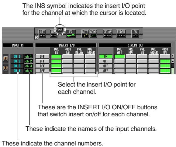
6 Click the INSERT I/O ON/OFF button for the desired channel to turn it on.
This enables the insert connection for the corresponding channel.
If you selected AD IN as the insert-in, or if you selected a slot to which an external head amp supporting the special protocol (Yamaha AD8HR, AD824) is connected, make head amp settings as necessary ( p.44).
Directly outputting the signal of an input channel
Here's how the signal being input to an input channel or ST IN channel can be output directly from the desired output jack.
1 In the DISPLAY ACCESS section, press the INPUT [PATCH] key several times to access the DIRECT OUT PATCH screen (INPUT PATCH function) shown below.
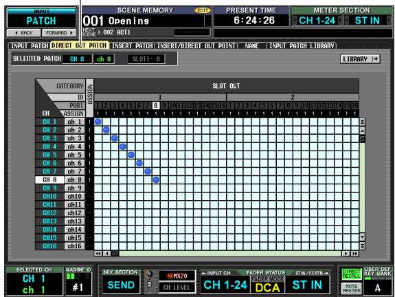
DIRECT OUT PATCH
In this screen you can select the output port that will directly output the input signal of an input channel or ST IN channel. You can select the following output ports.
| SLOT OUT 1-4 | Output channels of an I/O card installed in slots 1-4 |
| 2TR OUT D1-D3 | 2TR OUT DIGITAL jacks 1-3 (L/R) |
2 Click the grid at which the desired channel and output port intersect.
The procedure is the same as in the INPUT PATCH screen or OUTPUT PATCH screen. The SELECTED PATCH area at the upper left of the screen shows the channel and output port corresponding to the grid at which the cursor is located.
Note
With the procedure up to this point, the selected channel and output port are now patched. However, please note that direct output is not actually enabled until you turn on the DIRECT OUT ON/OFF button in the INSERT/DIRECT OUT screen described below.
3 Press the INPUT [PATCH] key several times to access the INSERT/DIRECT OUT POINT screen (INPUT PATCH function) shown below.
In the INSERT/DIRECT OUT POINT screen (INPUT PATCH function) you can switch direct output on/off, and select the direct out point (the location from which the signal is taken for direct output).
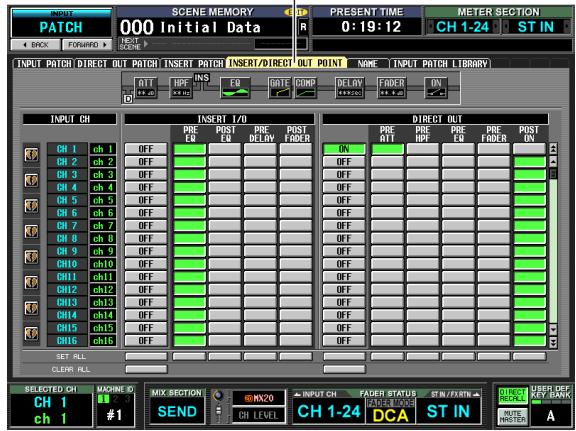
INSERT/DIRECT OUT POINT
4 Choose the direct out point for each channel from the following choices, and turn on the appropriate button.
| PRE ATT | Immediately before the attenuator |
| PRE HPF | Immediately before the HPF |
| PRE EQ | Immediately before the EQ (immediately after the PRE EQ of the INSERT I/O) |
| PRE FADER | Immediately before the fader |
| POST ON | Immediately after the [ON] key |
The selected point is indicated by the graphic in the upper part of the screen.

5 Click the DIRECT OUT ON/OFF button for the desired channel to turn it on.
This enables direct output for the corresponding channel.
9 Grouping and linking
This chapter explains DCA Groups and Mute Groups which let you control the level or muting of multiple channels simultaneously, and EQ Link and Compressor Link which let you link EQ or compressor parameters of multiple channels.
About DCA Groups and Mute Groups
You can use eight DCA groups and eight mute groups to control multiple channels simultaneously.
DCA groups allow the level of multiple channels to be controlled together by the DCA faders 1-8 of the top panel DCA strip. A single DCA fader will control the level of channels belonging to the same DCA group while maintaining the level difference between the channels. This provides a convenient way in which drum mics can be grouped.
DCA groups 1-6 are for input channels only, but DCA groups 7/8 can be used with both input channels and output channels. Both types of channel can exist in an identically-numbered group.
Mute groups allow multiple channels to be switched on/off simultaneously by the SCENE MEMORY [1]-[8] keys in the SCENE MEMORY section of the top panel. You can use this to cut out multiple channels simultaneously.
Mute groups 1-8 can be used with both input channels and output channels. Both types of channel can exist in an identically-numbered group.
Items in the ASSIGN MODE section
The ASSIGN MODE section lets you use the panel to assign channels to DCA groups or mute groups.
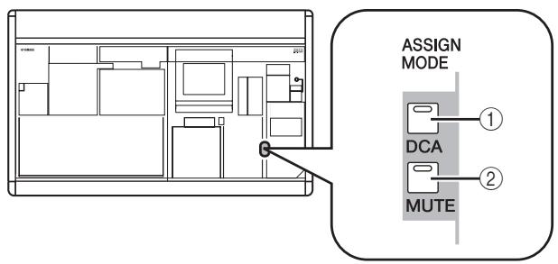
① ASSIGN MODE [DCA] key
This key lets you assign channels to DCA groups 1-8. While this key is blinking, you can use the [CUE] key of each channel to assign that channel to the currently selected DCA group.
② ASSIGN MODE [MUTE] key
This key lets you assign channels to mute groups 1-8. While this key is blinking, you can use the [CUE] key of each channel to assign that channel to the currently selected mute group.
Items in the DCA strip
The DCA strip is where you control DCA groups 1-8.
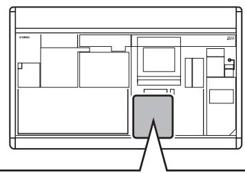
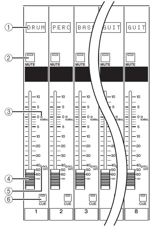
① Name indicator
This indicates the name assigned to each DCA group.
② DCA [MUTE] key
This switches DCA group muting on/off. If you turn this key on (LED lit), channels assigned to that DCA group will be muted.
DCA [NOMINAL] LED
This LED will light when the corresponding DCA fader is at the 0 dB position.
④ DCA fader
This fader adjusts the level of the DCA group.
⑤ DCA [RCL SAFE] LED
If Recall Safe is enabled for a DCA group, the corresponding LED will light.
⑥ DCA [CUE] key
This key is used to cue-monitor all channels assigned to that DCA group.
Using DCA Groups
Here we explain how to assign channels to DCA groups and use the DCA faders to control them.
Assigning channels to DCA groups
From the panel, you can assign channels to DCA groups either by selecting a specific channel and specifying the DCA group to which it will belong, or by selecting a specific DCA group and specifying the channels that will belong to that DCA group.
To select the DCA groups to which a specific channel will belong
1 Press a [SEL] key to select the channel for which you want to make assignments.
2 In the SELECTED CHANNEL section, press a DCA [1]-[8] key to select the DCA group to which the channel will be assigned (you may select more than one DCA group).
The LEDs will light for DCA [1]–[8] key(s) that are turned on. If an input channel is selected, its corresponding DCA assign LED(s) in the channel strip will also light.
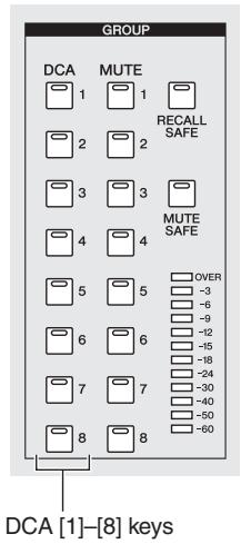
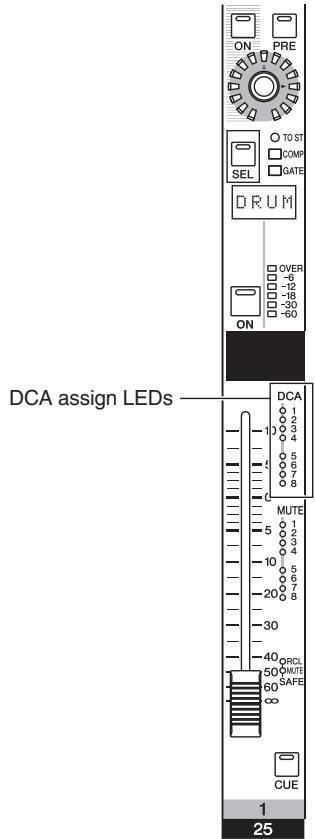
3 Select the DCA group(s) for other channels in the same way.
To select the channels that will belong to a specific DCA group
1 In the ASSIGN MODE section, press the ASSIGN MODE [DCA] key.
The ASSIGN MODE [DCA] key will blink. The [DCA] key of the FADER MODE section will also blink. While this key is blinking, you can use the [CUE] key of each channel to assign that channel to a DCA group.
2 Press a DCA [CUE] key in the DCA strip to select the DCA group (1-8) to which you want to assign channels.
3 Press the [CUE] key of input channels / output channels (you may select more than one) to assign them to the selected DCA group.
If a DCA group 1-6 is selected, you can select only input channels. If a DCA group 7/8 is selected, you can select input channels and output channels. If an input channel is selected, its corresponding DCA assign LED(s) in the channel strip will also light.
4 Assign channels to other DCA groups in the same way.
5 When you have finished making assignments, press the ASSIGN MODE section ASSIGN MODE [DCA] key to make its LED go dark.
The FADER MODE section [DCA] key will also stop blinking, and return to its previous state.
Hint
- You can also assign channels to DCA groups from within the display. Input channel DCA assignments are made in the INPUT DCA/GROUP function DCA GROUP ASSIGN screen (▶ p.296), and output channel DCA assignments are made in the OUTPUT DCA/GROUP function DCA GROUP ASSIGN screen (▶ p.258).
- DCA group settings are saved as part of the scene.
Controlling DCA groups
Here's how you can use the DCA strip to control DCA groups.
1 In the FADER MODE section, make sure that the FADER MODE [DCA] key LED is lit.
The FADER MODE section selects the function of the DCA strip faders. When the FADER MODE [DCA] key LED is lit, you can use the faders of the DCA strip to control DCA groups 1-8.
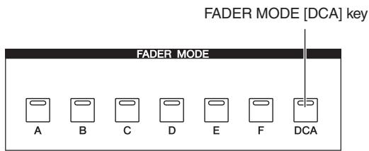
2 Use the faders of the channel strip to adjust the relative levels between the channels belonging to the DCA group you want to use.
3 Operate the DCA fader for the DCA group you want to use.
The level of the channels assigned to that DCA fader will change while preserving the level differences you established in step 2.
4 If you want to mute a DCA group, press the [MUTE] key for that DCA group in the DCA strip.
The [MUTE] key will light, and muting will be turned on for channels belonging to that DCA group (the same state as if the faders were lowered to - dB). At this time, the name indicator for that DCA group will be dimmed.
Hint
If desired, you can cause the DCA assign LEDs of the corresponding input channels to blink while the DCA group is muted. To do so, turn on the DCA/MUTE FLASH INDICATE setting in the PREFERENCE 1 screen (UTILITY screen).
5 To un-mute a DCA group, press the lit [MUTE] key in the DCA strip.
Using mute groups
This section explains how to assign channels to mute groups and use the panel keys to control them.
Assigning channels to mute groups
From the panel, you can assign channels to mute groups either by selecting a specific channel and specifying the mute groups to which that channel will belong, or by selecting a specific mute group and specifying the channels that will belong to that mute group.
To select the mute groups to which a specific channel will belong
1 Press a [SEL] key to select the channel for which you want to make assignments.
2 In the SELECTED CHANNEL section, use the MUTE [1]-[8] keys to select the mute group to which the channel will be assigned (you may select more than one mute group).
The LEDs will light for MUTE [1]–[8] key(s) that are turned on. If an input channel is selected, its corresponding mute assign LED(s) in the channel strip will also light.
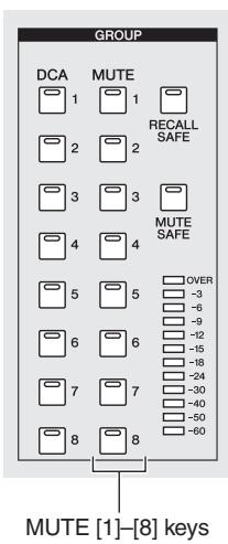
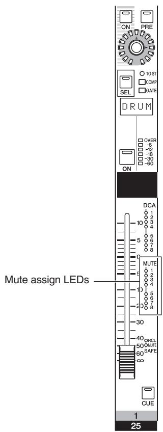
3 Select the mute group(s) for other channels in the same way.
To select the channels that will belong to a specific mute group
1 In the ASSIGN MODE section, press the ASSIGN MODE [MUTE] key.
The ASSIGN MODE [MUTE] key will blink. In the SCENE MEMORY section, the MUTE MASTER LED will also blink. While this key is blinking, you can use the [CUE] key of each channel to assign that channel to a mute group.
2 In the SCENE MEMORY section, use the SCENE MEMORY [1]-[8] keys to select the mute group (1-8) for which you want to make assignments.
While the ASSIGN MODE [MUTE] key is blinking, you can use the SCENE MEMORY [1]-[8] keys to select the mute group for which you will make assignments. Press one of these keys; the LED of that key will blink.
3 Press the [CUE] key of input channels / output channels (you may select more than one) to assign them to the selected mute group.
The [CUE] key will light, and that channel will be assigned to the selected mute group.
Both input channels and output channels can be assigned to mute groups 1-8.
4 Assign channels to other mute groups in the same way.
5 When you have finished making assignments, press the ASSIGN MODE section ASSIGN MODE [MUTE] key to make its LED go dark.
The SCENE MEMORY section MUTE MASTER/DIRECT RECALL LED will also return to its previous state.
Hint
- You can also assign channels to mute groups from within the display. Input channel assignments are made in the INPUT DCA/GROUP function MUTE GROUP ASSIGN screen (p.297), and output channel assignments are made in the OUTPUT DCA/GROUP function MUTE GROUP ASSIGN screen (p.259).
- Mute group assignments are saved as part of the scene.
Controlling mute groups
Here's how you can use the SCENE MEMORY [1]–[8] keys of the SCENE MEMORY section to switch mutating on/off for mute groups 1–8.
1 Turn on the MUTE MASTER button located in the lower right of the display.
The DIRECT RECALL button and MUTE MASTER button located in the lower right of the display select the function of the SCENE MEMORY [1]-[8] keys.
- When the DIRECT RECALL button is on
-
The SCENE MEMORY [1]–[8] keys will directly recall the scene that is assigned to each key.
-
When the MUTE MASTER button is on
The SCENE MEMORY [1]-[8] keys will switch mut-ing on/off for mute groups 1-8.
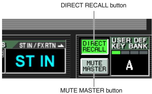
2 Press the SCENE MEMORY [1]-[8] key for the mute group you want to mute.
The key LED will light, and all channels belonging to the selected mute group will be muted (the same state as when the [ON] key is turned off). You can turn on more than one key to mute multiple mute groups.
3 To un-mute a mute group, press a lit SCENE MEMORY [1]-[8] key.
Hint
- The mute group mute on/off status is saved in the scene. However, you can also use the Recall Safe function to exclude the mute group status from scene recall.
- If desired, you can cause the MUTE assign LEDs of the corresponding input channels to blink while the mute group is muted. To do so, turn on the DCA/MUTE FLASH INDICATE setting in the PREFERENCE 1 screen (UTILITY screen).
Using the Mute Safe function
If necessary, channels belonging to a mute group can be temporarily excluded from mute group operations (Mute Safe).
1 Press a [SEL] key to select the channel you want to exclude from mute groups.
2 In the SELECTED CHANNEL section, press the [MUTE SAFE] key to make the LED light.
Mute Safe will be enabled for the corresponding channel. (In the case of an input channel, the [MUTE SAFE] LED in the channel strip will light.) In this state, mating an applicable mute group will not affect that channel.
3 To defeat Mute Safe, press the SELECTED CHANNEL section [MUTE SAFE] key once again to make the LED go dark.
Hint
Mute Safe settings are not saved in the scene. They will remain effective until you manually defeat them.
EQ Link and Compressor Link are functions that respectively link the EQ parameters or compressor parameters of multiple channels. Editing the EQ or compressor parameters of any channel belonging to a link group will similarly edit the other channels in that link group.
1 In the DISPLAY ACCESS section, press the INPUT [DCA/GROUP] key (for an input channel) or OUTPUT [GROUP] key (for an output channel) to access one of the following screens.
- INPUT DCA/GROUP function EQ LINK ASSIGN screen
Assign EQ link groups (1-8) for input channels
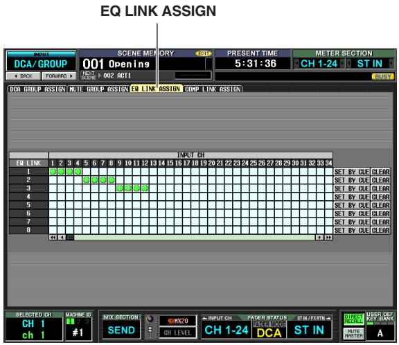
- INPUT DCA/GROUP function COMP LINK ASSIGN screen
Assign compressor link groups (1-8) for input channels
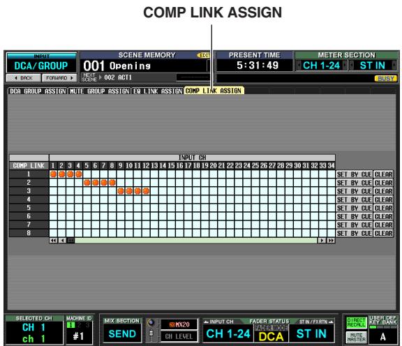
OUTPUT DCA/GROUP function EQ LINK ASSIGN screen
Assign EQ link groups (A-F) for output channels
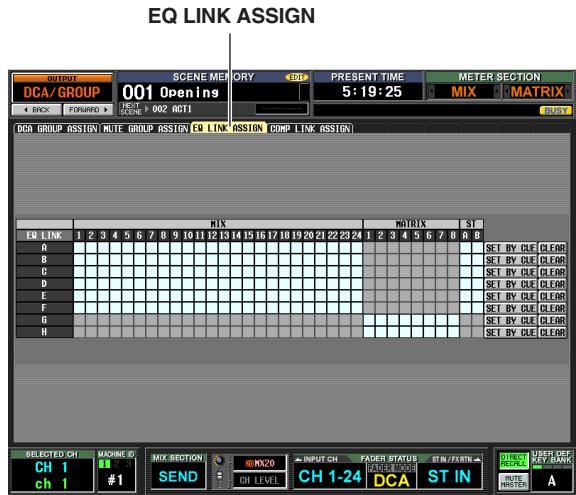
OUTPUT DCA/GROUP function COMP LINK ASSIGN screen
Assign compressor link groups (A-F) for output channels
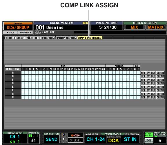
In each screen, the channels (assignment source) are listed horizontally, and the link group number or alphabetical character (assignment destination) are listed vertically.
Hint
The EQ link groups and compressor link groups are independent for input channels and output channels.
2 Click the grid at which the desired channel (assignment source) intersects the desired link group (assignment destination).
A " ⑤ " symbol will appear at the corresponding grid.
To cancel the assignment, click the " " symbol once again.
In the case of output channel EQ link groups, MIX channels and STEREO A/B channels can be assigned only to groups A-F, and MATRIX channels can be assigned only to groups G/H. (Unavailable grids are grayed-out.)
If another channel is already assigned to the assignment-destination group, the EQ and compressor parameters of the previously-assigned channel will be copied to the channel that is added later, causing the settings to be the same.
3 If you want to use the [CUE] key of each channel to assign it to a link group, click the SET BY CUE button for the corresponding link group in the screen to turn it on.
While the SET BY CUE button is on, you can use the channel [CUE] keys to set or cancel link group assignments.
![YAMAHA PM5D-RH - If you want to use the [CUE] key of each channel to assign it to a link group, click the SET BY CUE button for the corresponding link group in the screen to turn it on. - 1](/content/2025/01/115055/images/030b58f463d01034cf6557ab81f45a910ae0e2da952b7c678bd1c5573ee976ef.jpg)
Note
- The SET BY CUE button can be turned on for only one link group.
- When you switch to a different screen, the SET BY CUE button that was turned on will automatically be defeated.
4 When you have finished making link group assignments, operate the EQ or compressor parameters of a channel belonging to a link group.
The EQ or compressor parameters of channels belonging to the same link group will follow your editing.
Hint
Link group settings are saved as part of the scene.
Note
The STEREO LINK button and KEY IN SOURCE settings are not linked even for channels belonging to the same compressor link group.
10 Scene memory
This chapter explains how to store and recall the PM5D's mix parameters as "scenes."
About scenes
The PM5D can store and recall the current state of its mix parameters as a "scene." Scenes are assigned a scene number of 000-500. Scene 000 is read-only, and cannot be overwritten. Other scene numbers may be rewritten freely.
A scene contains the settings of the panel controls (except for the TALKBACK section, CUE/MONITOR section, and the AD IN section of the PM5D model) as well as the settings of the functions and screens listed below.
- INPUT function settings
- OUTPUT function settings
- EFFECT PARAM screen settings
- GEQ PARAM screen settings
- SELECTIVE RECALL screen (SCENE function) settings
- FADE TIME screen (SCENE function) settings
- MIXER SETUP screen (SYS/W.CLOCK function) settings
- HA screen (SYS/W.CLOCK function) settings
However, input patch, output patch, and HA (head amp) settings are saved in the corresponding library, and the scene contains only a library number that links to these saved settings.
For example if the input patch, output patch, and HA (head amp) settings have been edited when you store a scene, the changes will be stored in the corresponding library, and the library number of these stored library items will be stored in the scene.
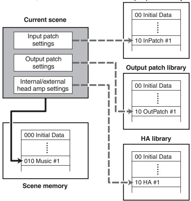
- Storing a scene
Hint
You can choose how the changes will be stored in the library; they can either be stored in a new unused library number, or overwritten onto the existing library number (→ p.89).
When you recall a scene, the input patch, output patch, and HA (head amp) library numbers linked to that scene will be recalled simultaneously.

Recalling a scene
For each scene, you can specify whether to enable linking to these libraries (→ p.175). For example if you turn off linking to the HA library for a certain scene, recalling that scene will not update the HA settings.
Note
By "head amp settings" we mean settings for the internal head amps of the PM5D-RH model and for an external head amp device that supports the special protocol (e.g., Yamaha AD8HR or AD824). The settings of the AD IN section of the PM5D model are not included.
Hint
If the PM5D and DSP5D are cascade-connected, storing a scene will cause the scene data to be stored in each the PM5D and in the DSP5D.
When a scene is recalled, the same scene number is recalled on all PM5D/DSP5D units.
Items in the SCENE MEMORY section
The SCENE MEMORY section lets you store and recall mix parameters as scene memories. Mute operations for mute groups 1-8 are also performed in this section.
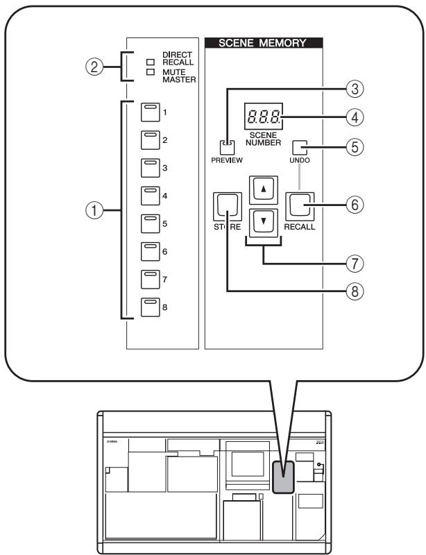
① SCENE MEMORY [1]–[8] keys
The function of these keys will depend on the selection of the DIRECT RECALL button and MUTE MASTER button in the lower right of the display.
![YAMAHA PM5D-RH - ① SCENE MEMORY [1]–[8] keys - 1](/content/2025/01/115055/images/a491fb9921b24911b7c402d251a67b5d764f0249eaaa7c60bb3cc63e7c3bcf77.jpg)
- When the DIRECT RECALL button is on SCENE MEMORY [1]–[8] keys operate as Direct Recall keys that directly recall the eight scenes assigned to these keys.
- When the MUTE MASTER button is on SCENE MEMORY [1]–[8] keys operate as Mute Master keys that switch muting on/off for mute groups 1–8.
(2) [DIRECT RECALL]/[MUTE MASTER] indicators
These indicators indicate the currently selected function of the SCENE MEMORY [1]-[8] keys (①).
③ SCENE MEMORY [PREVIEW] key
This key selects either NORMAL mode or Preview mode as the operation when you recall a scene. PREVIEW mode is selected if this key LED is lit; NORMAL mode is selected if it is dark. Operation will differ as follows according to the selected mode.
NORMAL mode
This mode lets you store and recall scenes as usual. When you recall a scene in this mode, the current scene will be overwritten by the settings of the newly recalled scene.
- PREVIEW mode
This mode lets you preview the settings of a scene stored in memory without affecting the signal processing of the current scene. When you recall a scene in this mode, the mix parameter values of that scene will be shown in the PM5D's panel, but the internal signal processing will remain as it was before the recall. When you operate the panel keys or encoders at this time, the panel display will change but internal signal processing will not be affected. If desired, you can save the edited content in the desired scene number or library number.
④ Scene number indicator
This indicate shows the number (000-500) of the scene that is selected for store or recall.
⑤ SCENE MEMORY [UNDO] key
This key cancels the most recently-executed scene recall operation. If you have accidentally recalled an unwanted scene, you can press this key to return to the state prior to recalling the scene.
⑥ SCENE MEMORY [RECALL] key
This key recalls the scene whose number is shown in the scene number indicator (④).
⑦ SCENE MEMORY [▲] /[▼] keys
These keys increment or decrement the number displayed in the scene number indicator (④) . However if the SCENE screen BLANK SKIP button is turned on, you will only be able to select numbers in which a scene is actually stored.
⑧ SCENE MEMORY [STORE] key
This key stores the current scene into the number shown by the scene number indicator (4).
Storing a scene
Here's how to store the current mix settings (the current scene) into a scene memory.
Note
Before you continue with the following procedure, make sure that the SCENE MEMORY section SCENE MEMORY [PREVIEW] key is off (dark). (If it is on, turn it off.)
1 Use the PM5D's panel controls to set the mix parameters as desired.
2 Use the SCENE MEMORY [▲]/[▼] keys to select the store-destination scene number.
When you select a new scene number, the scene number and name shown at the top of the display and the scene number shown in the scene number indicator of the SCENE MEMORY section will blink. This blinking indicates that the settings of the indicated scene differ from the currently-set mix parameters.
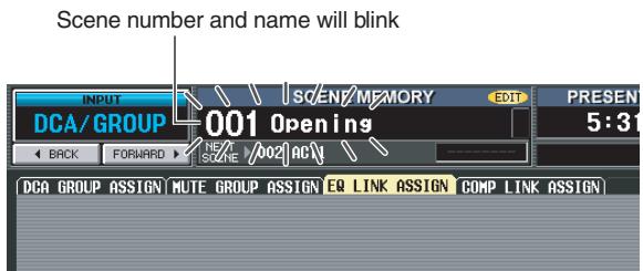

3 Press the SCENE MEMORY [STORE] key.
The SCENE STORE window will appear, allowing you to assign a title to the scene and store it. This window shows the following information.
As the default choice in which edited library settings will be stored when you store a scene, choose either NEW (select an unused library) or OVERWRITE (select the original library).
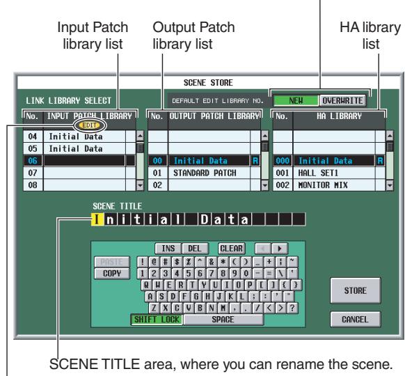
An "EDIT" indicator appears here if the library settings have been modified from the state in which they were last stored.
4 Use the SCENE TITLE area to assign a name to the scene. (For details on how to input text p.30)
5 As desired, specify the library numbers in which the input patch, output patch, and HA settings will be stored.
To specify a store-destination library number, scroll the input patch, output patch, or HA library list, and click the desired number. (The number currently selected as the store-destination is highlighted.) The library number you select here is saved as part of the scene.
The default selection of store-destination will depend on the setting in the DEFAULT EDIT LIBRARY NO. area.
- If the NEW button is on
The lowest of the unused library numbers will be selected.
- If the OVERWRITE button is on
The number from which the library was originally recalled will be selected. (If this was a read-only library item, the lowest-numbered unused library number will be selected.)
6 Click the STORE button in the window.
A message will ask you to confirm the store operation.
7 Click the OK button.
The current settings will be stored to the scene number you selected in step 2, and the upper part of the screen and the scene number indicators will stop blinking. If any changes have been made to the input patch, output patch, and HA settings used by this scene, they will be stored in the corresponding library number.
Recalling a scene
Here's how to recall a stored scene from memory.
Note
Before you continue with the following procedure, make sure that the SCENE MEMORY section SCENE MEMORY [PREVIEW] key is off (dark). (If it is on, turn it off.)
1 Use the SCENE MEMORY [ ] / [ ] keys to select the scene number that you want to recall.
When you select a new scene number, the scene number and name shown at the top of the display and the scene number shown in the scene number indicator of the SCENE MEMORY section will blink.
2 Press the SCENE MEMORY [RECALL] key.
A message in the display will ask you to confirm the recall operation. When you click the OK button, the scene number you selected in step 1 will be recalled. If input patch, output patch, and HA libraries are linked to that scene, the correspondingly numbered libraries will also be recalled.
Hint
If desired, you can disable the link between the scene and these libraries, so that specific libraries will not be updated when you recall that scene.
Using PREVIEW mode
Preview mode lets you check or edit the settings of a scene stored in memory without affecting the signal processing of the current scene. When you recall a scene in this mode, the settings of the newly recalled scene will appear on the PM5D's panel, but the internal signal processing will remain as it was prior to the recall.
During an actual performance, it can be convenient to use this to check the content of the scene you intend to recall next, or to make minor changes to a scene and then store it.
1 In the SCENE MEMORY section, turn on the SCENE MEMORY [PREVIEW] key.
The key LED will light, and the SCENE MEMORY section will operate in PREVIEW mode. At this time, the scene indicator at the top of the display will turn red, and the "PREVIEW" indicator will appear.
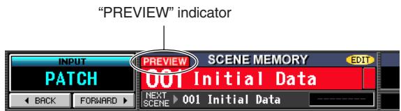
While in PREVIEW mode, operating the knobs, encoders, and other controls (except for the TALK-BACK section, CUE/MONITOR section, and the AD IN section of the PM5D model) will not affect the audio signal processing.
2 Use the SCENE MEMORY [ ] / [ ] keys to select the scene number that you want to recall.
The scene number will light in the scene number indicator.
3 Press the SCENE MEMORY [RECALL] key.
Only the setting values of the scene you selected in step 2 will be loaded and shown in the PM5D's panel LEDs and display. However, the internal signal processing of the system will remain unchanged as it was prior to the Recall operation.
If desired, you can access a specific channel in the SELECTED CHANNEL section, or access a specific screen in the display to examine the values in detail.
4 If desired, use the controls of the console to edit the settings.
Operating a panel control in PREVIEW mode will edit the settings of the scene you recalled in step 3, but will not affect the PM5D's internal signal processing.
5 If you want to store the changes you made in step 4, select the scene number in which you want to store the scene, and press the SCENE MEMORY [STORE] key.
The settings you edited in step 4 will be stored into memory.
6 To return the SCENE MEMORY section to NORMAL mode operation, press the SCENE MEMORY [PREVIEW] key to make the key LED go dark.
Note
- PREVIEW mode applies to all parameters included in scene memory, all parameters included in the INPUT PATCH and OUTPUT PATCH functions, and HA parameters. PREVIEW mode does not apply to parameters other than these.
- Even while you are in PREVIEW mode, recall operations in the EVENT LIST screen or via MIDI messages will apply to the current scene. While in PREVIEW mode, operations of parameters that can be edited in the USER DEFINED screen will generally apply to PREVIEW mode, not to the current scene.
With the PM5D's default settings, pressing the SCENE MEMORY [STORE] key will open the SCENE STORE window where you can name the scene and store it. If you enable the Auto Store function, you can execute the Store operation simply by pressing the SCENE MEMORY [STORE] key twice. Here's the procedure.
1 In the DISPLAY ACCESS section, press the [UTILITY] key several times to access the PREFERENCE 1 screen shown below.
The PREFERENCE 1 screen is where you can make various default settings for the PM5D.
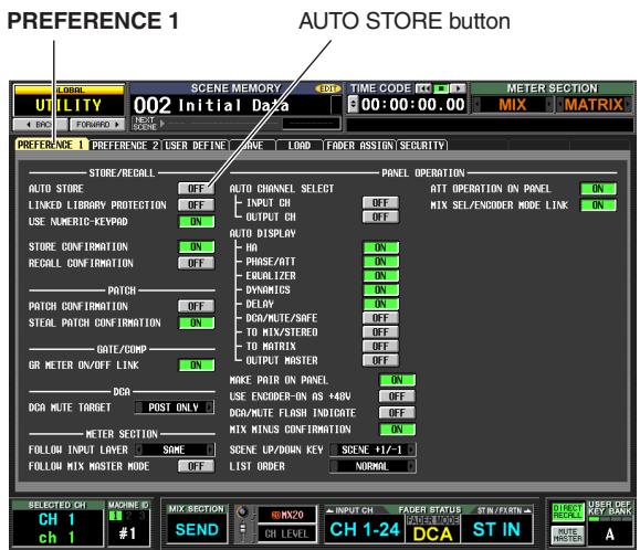
2 In the STORE/RECALL area at the upper left of the screen, turn on the AUTO STORE button.
The Auto Store function is now enabled. When you press the SCENE MEMORY [STORE] key once, the SCENE STORE window will appear as usual; press the key once again to execute the Store operation. If you rapidly press the key twice, the Store operation will be executed before the SCENE STORE window appears.
Note
Note that if the STORE CONFIRMATION button is turned on in the STORE/RECALL area of this PREFERENCE 1 screen, a window will ask you to confirm the Store operation even if Auto Store is enabled. If you don't want any windows to appear, turn off the STORE CONFIRMATION button as well.
Using the Direct Recall function
If you assign frequently-used scenes to the SCENE MEMORY [1]–[8] keys of the SCENE MEMORY section, you will be able to recall these scenes with a single keystroke.
1 In the DISPLAY ACCESS section, press the [SCENE] key several times to access the SCENE screen shown below.
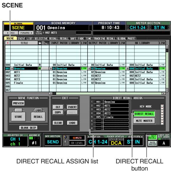
In the SCENE screen you can use the DIRECT RECALL ASSIGN list shown in the lower middle of the screen to assign scene numbers to the SCENE MEMORY [1]-[8] keys.
2 Use the DIRECT RECALL ASSIGN list to assign a scene number to a SCENE MEMORY [1]-[8] key.
Move the cursor to the left-hand field of the DIRECT RECALL ASSIGN list and turn the [DATA] encoder or click the 1 / 2 buttons to select a scene number; the scene name will appear in the field at right.
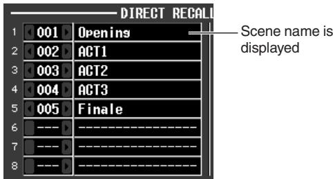
3 Assign scene numbers to other keys in the same way.
4 In the KEY MODE area at the right side (or lower right) of the screen, make sure that the DIRECT RECALL button is turned on. (If it is off, click the DIRECT RECALL button.)
When the DIRECT RECALL button is on, the SCENE MEMORY section [DIRECT RECALL] LED will light, and the SCENE MEMORY [1]-[8] keys will operate as Direct Recall keys.
5 In the SCENE MEMORY section of the console, press one of the SCENE MEMORY [1]-[8] keys.
The LED of the corresponding key will light, and the scene assigned to that key will be recalled.
Using the Selective Recall function
"Selective Recall" is a function that lets you restrict the parameters or channels that will be updated when you recall a specific scene, or, conversely, specify for each scene parameters or channels that will be excluded from recall operations.
Hint
As a function similar to Selective Recall, there is also a "Recall Safe" function that lets you select channels and parameters to be excluded from recall operations (p.94). However it differs from Selective Recall in that Recall Safe settings apply to all scenes.
In the DISPLAY ACCESS section, press the [SCENE] key several times to access the SELEC-TIVE RECALL screen shown below.
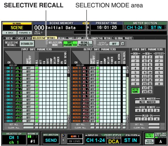
2 In the SELECTION MODE area in the upper middle of the screen, choose one of the following two selection modes to specify how the SELECTIVE RECALL screen will operate.
- SAFE PARAMETER mode
Specify channels/parameters that will be excluded from Recall operations. - RECALL PARAMETER mode
Specify channels/parameters that will be affected by Recall operations.
When you click a button to change the mode, a confirmation window will appear. Immediately after you switch modes, all channels/parameters will be subject to recall.
3 Use the buttons in the screen to select the parameters/channels that will be subject to recall (or excluded from recall).
The SELECTIVE RECALL screen is divided into three areas. From the left, these areas let you make settings for input channels, output channels, and other parameters. The buttons in the screen correspond to parameters and channels as follows.
Input channels / Output channels
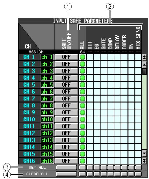
① SAFE ON/OFF RECALL ON/OFF
The functions and names of these buttons will depend on the currently-chosen SELECTION MODE.
- SAFE PARAMETER mode
The buttons will function as SAFE ON/OFF buttons to select the channels that will be excluded from Recall. - RECALL PARAMETER mode
The buttons will function as RECALL ON/OFF buttons to select the channels that will be subject to Recall.
② Parameter matrix grid
Here you can select the parameters that will be excluded from (or subject to) Recall. If the ALL button is on, all parameters will be excluded from (or subject to) Recall.
③ SET ALL
Turns on all buttons for all input channels/output channels or for the corresponding parameter.
(4) CLEAR ALL
Turns off all buttons for all input channels/output channels or for the corresponding parameter.
Other parameters
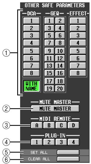
① DCA/GEQ/EFFECT
These buttons specify whether DCA groups, GEQ modules, and internal effects will be excluded from (or subject to) Recall.
Note
DCA groups provide a WITH NAME button. This button excludes the DCA group name from the recall operation (or selects it as the object of recall).
(2) MUTE MASTER
This button specifies whether the Mute Master key on/off status will be excluded from (or subject to) Recall.
③ MIDI REMOTE (PM5D only)
These buttons specify whether MIDI remote layers A-D will be excluded from (or subject to) Recall.
④ PLUG-IN (PM5D only)
These buttons specify whether the Waves plug-in DSP cards Y96K installed in slots 1-4 will be excluded from (or subject to) Recall.
⑤ SET ALL
This button turns on all buttons for parameters ①-④.
(6) CLEAR ALL
This button turns off all buttons for parameters ①-④.
4 In the upper left of the screen, switch the SELECTIVE RECALL ENABLED/DISABLED button to ENABLED.
When this button is set to ENABLED, the Selective Recall function will apply to subsequently-stored scenes.
5 Store the current scene.
The settings of the SELECTIVE RECALL screen will be saved as part of the scene. When you recall this scene, only the selected channels/parameters will be excluded from (or subject to) Recall.
Note
- If you edit the settings of the SELECTIVE RECALL screen, you must store that scene in order to make your changes effective.
- Recall Safe and Selective Recall can be used together. Channels/parameters excluded from recall operations by either Recall Safe or Selective Recall (or both) will not be recalled.
Using the Recall Safe function
"Recall Safe" is a function that excludes only specific parameters/channel from Recall operations. This differs from the Selective Recall settings (p.92) made for individual scenes in that Recall Safe settings are common to all scenes.
1 In the DISPLAY ACCESS section, press the [SCENE] key several times to access the RECALL SAFE screen shown below.
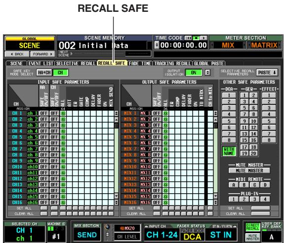
2 Use the buttons in the screen to select the parameters/channels that will be excluded from Recall operations.
The function of the buttons in the screen and the procedures are the same as in the SELECTIVE RECALL screen (when SAFE PARAMETER mode is selected), except for the fact that HA (Head Amp) SAFE ON/OFF button is added as a parameter in the INPUT SAFE PARAMETER area.
The [RCL SAFE] indicator of the channel strip will light for input channels, STEREO A/B channels, and DCA groups for which Recall Safe is turned on.
Hint
- In the RECALL SAFE screen, clicking the parameter matrix grid will display a “G” symbol with a “G” character in the center. This “G” indicates that the setting is global, and applies to all scenes.
- If desired, you can copy and paste Selective Recall settings from the currently selected scene into the RECALL SAFE screen (p.183).
- If you scroll the scroll bar downward, you will see that the CH column of the SAFE PARAMETERS area shows not only input channels but also input ports. If you set the HA of a certain input port to Recall Safe, the HA of the corresponding channel will also be set to Recall Safe. Even if they are assigned to multiple channels, the HA Recall Safe settings for corresponding input ports/channels will be linked.
- If necessary, you can turn on the HA+CH button in the SAFE KEY MODE SELECT area, so that when recall safe is turned on/off using the panel [RECALL SAFE] key or the RECALL SAFE button in the CH VIEW screen (INPUT VIEW function), recall safe will be also be turned on/off for the HA patched to the corresponding channel.
- Separately from the conventional Recall Safe functionality, the OUTPUT ISOLATION field allows you to specify output channels and parameters excluded from recall to be memorized in SETUP memory (which is not subject to memory card load operations) ( p.182).
3 If you want to use the panel to switch Recall Safe on/off for a channel, use the [SEL] key to select a channel and then press the SELECTED CHANNEL section [RECALL SAFE] key to make the key LED light.
Recall Safe will be turned on for the corresponding channel.
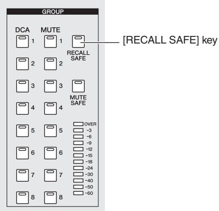
Note
By default, ALL is selected as the parameters that will be excluded from recall. This means that if you turn on Recall Safe from the panel, the Recall Safe setting will affect all parameters of the channel(s) for which it is turned on.
After you have finished making Recall Safe settings and you recall a scene, only the selected channels/parameters will be excluded from the Recall operation.
Note
Recall Safe and Selective Recall can be used together. Channels/parameters excluded from recall operations by either Recall Safe or Selective Recall (or both) will not be recalled.
"Fade" is a function that smoothly changes fader and pan to their new values over a specified duration when you recall a scene. The settings of the Fade function are made independently for each scene.
1 In the DISPLAY ACCESS section, press the [SCENE] key several times to access the FADE TIME screen shown below.
In this screen you can select the channels that will use the Fade function, and specify the fade time and start offset time.
![YAMAHA PM5D-RH - In the DISPLAY ACCESS section, press the [SCENE] key several times to access the FADE TIME screen shown below. - 1](/content/2025/01/115055/images/bd77b649d9380829fabc43b78ead4a4d3685925f6f60c3181d87494f350861d9.jpg)
2 In the upper left of the screen, click the FAD-ING ENABLED/DISABLED button to select ENABLED.
When the FADING ENABLED/DISABLED button is set to ENABLED, the Fade function will be enabled for the faders in the current scene.
3 In the upper right of the screen, make sure that the FADE TIME button is on.
The FADE TIME/START OFFSET buttons in the upper right of the screen select the parameter that will be edited in the lower part of the FADE TIME screen. When this button is on, you can specify the fade time (the time over which fader and pan parameters will reach their new value) for each channel.
4 In the rows of buttons at the bottom of the screen, click to turn on the buttons of the channels for which you want to enable the Fade function.
By clicking the SET ALL buttons located at the right of the screen, you can turn on the buttons of all input channels and all DCA groups, or the buttons of all output channels.
By clicking the CLEAR ALL buttons located at the right of the screen, you can turn off the buttons of all input channels and all DCA groups, or the buttons of all output channels.
5 Move the cursor to the box located immediately below each button, and turn the [DATA] encoder to specify the fade time for that channel. (Alternatively, click the 4 / 6 buttons at the left and right of the box.)
![YAMAHA PM5D-RH - Move the cursor to the box located immediately below each button, and turn the [DATA] encoder to specify the fade time for that channel. (Alternatively, click the 4 / 6 buttons at the left and right of the box.) - 1](/content/2025/01/115055/images/ec4689635a43dae2abd0c45e19ff24b9d516745085efea89f9036e1f5c675fa1.jpg)
Hint
If the numerical value is displayed in light blue when you perform the above actions, this indicates that an offset time has been specified for the corresponding channel.
6 In the same way, specify the fade time for other channels as well.
If desired, you can easily copy the fade time setting of a channel to another channel ( p.185).
7 In the upper right of the screen, click the START OFFSET button to turn it on.
When the START OFFSET button is on, you can specify an offset time for each channel (the time from when the scene is recalled until the fader or pan parameter begins to change).
As you did in steps 4-6, specify an offset time for each channel.
9 If you want to enable the Fade function not only for faders but also for the PAN (BALANCE) parameters of input channels, set the INPUT CH PANNING ENABLED/DISABLED button (located in the upper middle of the screen) to ENABLED.

The FADING ENABLED/DISABLED button and INPUT CH PANNING ENABLED/DISABLED button can be set independently. Use the following two buttons to select the input channels to which this will apply.
- When the ALL INPUT button is on
The Fade function will apply to the pan (balance) parameter of all input channels.
- When the SAME AS FADING button is on
The Fade function will apply to the pan (balance) parameters of only the input channels selected in step 4.
10 When you have finished making settings, store the scene.
The settings in the FADE TIME screen are saved independently for each scene. The Fade function will apply when you recall a scene for which this button is set to ENABLED. After recall, the fader and pan (balance) parameter values will begin changing when the specified Start Offset Time has elapsed, and will reach their new values over the specified Fade Time.
Using the Tracking Recall function
"Tracking Recall" is a function that adds a specified offset value to each fader or level value when a scene is recalled. Tracking Recall settings are common to all scenes. For example if the original level of a certain sound source has changed, or if an actor was replaced by an understudy, this function provides a convenient way to adjust the level of that specific channel for all scenes.
1 In the DISPLAY ACCESS section, press the [SCENE] key several times to access the TRACKING RECALL screen shown below.
In this screen you can select the channels that will use the Tracking Recall function, and specify the offset value for each channel.
![YAMAHA PM5D-RH - In the DISPLAY ACCESS section, press the [SCENE] key several times to access the TRACKING RECALL screen shown below. - 1](/content/2025/01/115055/images/56847c05ab4f5acef6b516e2b6e5f86e4b5bf7393c3ed6d35261073ff4cd29a4.jpg)
2 In the upper left of the screen, click the TRACKING RECALL ENABLED/DISABLED button to make it indicate ENABLED.
When the TRACKING RECALL ENABLED/DISABLED button is set to ENABLED, the Tracking Recall function will be enabled for all scenes.
3 Using the buttons of the DISPLAY SELECT area in the upper middle of the screen, select the type of channels for which you want to make settings.
- If the INPUT button is on
The screen will show the faders of input channels 1-48, ST IN channels 1-4, FX RTN channels 1-4, DCA groups 1-8, and STEREO A/B channels.
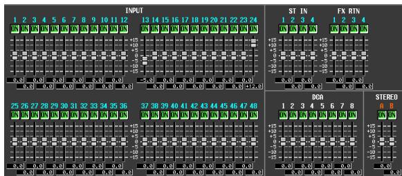
- If the OUTPUT button is on
The screen will show the faders of MIX channels 1-24, MATRIX channels 1-8, DCA groups 7/8, and STE-REO A/B channels.
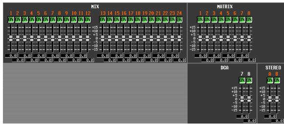
4 In the row of buttons above the faders in the screen, click to turn on the buttons of the channels for which you want to enable the Tracking Recall function.
Clicking the SET ALL button located in the upper right of the screen will turn on the buttons of all channels and DCA groups.
Clicking the CLEAR ALL button located in the upper right of the screen will turn off the buttons of all channels and DCA groups.
5 To set the offset value for each channel, drag the fader upward or downward for a channel whose button you have turned on.
When you turn on the setting for a channel in step 4, the offset value is set to 0. The offset value can be adjusted in a range of -15dB to +15dB . The current value is shown in the box immediately below the fader.
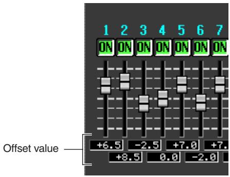
6 In the same way, specify the offset value for other channels as well.
7 When you have finished making settings, turn on the OFFSET LOCK button located in the upper right of the screen.
When this button is on, the offset values currently specified for the channels will be fixed; this prevents the offset values from being unintentionally changed.
When you recall a new scene in this state, the offset values will be added to the level of each channel when the scene is loaded. (However, the upper and lower level limits will not be exceeded.)
Note
Channels that are excluded from Recall operations by the Recall Safe or Selective Recall functions will not change even if Tracking Recall is turned on.
"Global Paste" is a function that lets you copy and paste settings of the desired channel or parameter from the current scene to scene data in memory (multiple selections are allowed). This is a convenient way in which changes to the current scene can be applied to scenes that have already been stored.
In the DISPLAY ACCESS section, press the [SCENE] key several times to access the GLOBAL PASTE screen shown below.
In this screen you can select the copy-source channels/ parameters and specify the paste-destination scene data.
![YAMAHA PM5D-RH - In the DISPLAY ACCESS section, press the [SCENE] key several times to access the GLOBAL PASTE screen shown below. - 1](/content/2025/01/115055/images/20eae3c713fbfcf30932d6aed1ec76473040075027d3665edbe9a8205e36e030.jpg)
2 Use the buttons in the PASTE MODE area to select one of the following as the type of item you want to paste.
| INPUT | Input channel parameters |
| OUTPUT | Output channel parameters |
| DCA, GEQ, EFFECT | DCA level or mute on/off status, GEQ settings, internal effect settings |
3 In the CURRENT SCENE area, select the copy-source channels or parameters.
The contents shown in the CURRENT SCENE area will depend on what you select in the PASTE MODE area.
- When PASTE MODE = INPUT
Select input channels in the left area, and select parameters in the right area. (For details on the parameters p.187).
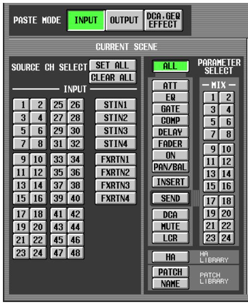
- When PASTE MODE = OUTPUT
Select output channels in the left area, and select parameters in the right area. (For details on the parameters p.187).
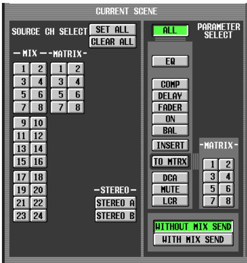
- When PASTE MODE = DCA, GEQ, EFFECT
Select DCA groups, GEQ modules, and internal effects.
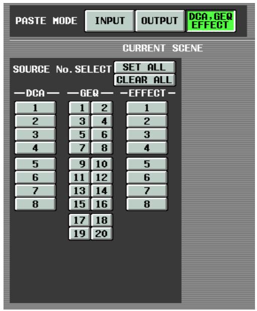
Hint
In either of these modes, you can click the SET ALL button to turn on all channels, or click the CLEAR ALL button to turn off all channels.
4 In the DESTINATION SCENE area, select the paste-destination scene(s).
To select a single scene, click the desired line in the upper half of the list.
To select multiple consecutive scenes, use the upper half of the list to click the scene number at which you want to begin pasting, and use the lower half of the list to click the scene number at which you want to stop pasting.
The order in which the scenes are listed can be changed by clicking one of the buttons at the top of the list; the
- button (sort by number), SCENE TITLE button (sort by scene title), or TIME STAMP button (sort by the date on which the scene was saved).
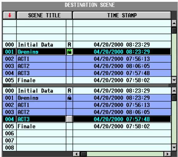
5 Click the PASTE button.
The selected items of the current scene will be pasted to the scene(s) in memory.
Note
- If the parameter settings differ between the copy-source and paste-destination, exception handling may be applied when the data is pasted (p.188).
- Only the parameters selected by PASTE MODE will be pasted. Note that even if you selected parameters in the CURRENT SCENE area, they will be excluded from the paste operation if you switch the PASTE MODE.
11 Monitor and Cue
This chapter explains the PM5D's Monitor and Cue functions.
About the MONITOR and CUE sections
The MONITOR section sends the signal selected as the monitor source to the MONITOR OUT jacks. You can select the following signals as the monitor source.
- The input signal from 2TR IN ANALOG jacks 1/2
The input signal from 2TR IN DIGITAL jacks 1-3 - The output signal of the STEREO A/B channels
The output signal of the LCR channels
The output signal of a pre-selected MIX channel 1-24 or MATRIX channel 1-8
Note
If the PM5D is cascade-connected to the DSP5D, the DSP5D's cue operations will occur in tandem.
The CUE section sends the cue signal of the channel/group selected by a panel [CUE] key to the CUE OUT jacks.
Hint
If the CUE INTERRUPTION button is turned on in the MONITOR screen (MON/CUE function), the Cue/Solo signal will also be sent from the MONITOR OUT jacks when Cue/Solo is active.
Note
Since the DSP5D does not have monitor functionality, the keys and knobs of the MONITOR section will always operate the settings of machine #1 (PM5D).
Similarly, the CUE [LEVEL] knob will always operate the settings of machine #1 (PM5D).
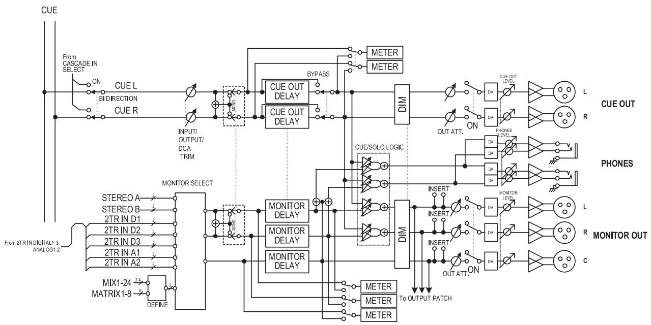
PM5D
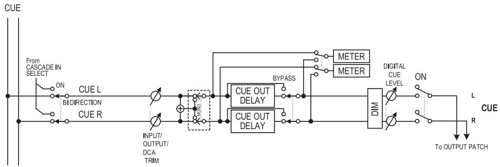
DSP5D
- MONITOR SELECT
Selects the monitor source.
- MONITOR DELAY
Delays the monitor signal.
- CUE OUT DELAY
Delays the cue signal.
METER
Switches the signal that is shown in the meter section or in the display.
DIM (Dimmer)
Attenuates the monitor/cue signal by a fixed amount.
- OUT ATT. (Output attenuator)
Attenuates/boosts the monitor/cue signal.
- ON (On/off)
Switches the monitor signal on/off.
PHONES LEVEL
Adjusts the output level of the top panel and front panel PHONES jacks.
- MONITOR LEVEL
Adjusts the monitor level.
CUE OUT LEVEL
Adjusts the output level of the cue signal.
Using the Monitor function
Items in the MONITOR section
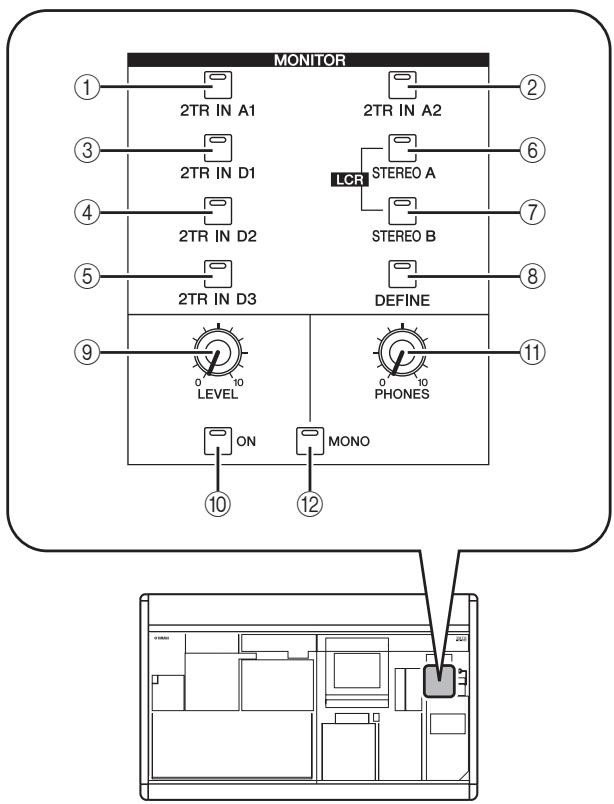
① [2TR IN A1] key
(2) [2TR IN A2] key
These keys select the input signals of 2TR IN ANALOG jacks 1 / 2 as the monitor source.
③ [2TR IN D1] key
(4) [2TR IN D2] key
(5) [2TR IN D3] key
These keys select the input signals of 2TR IN DIGITAL jacks 1-3 as the monitor source.
(6) [STEREO A] key
⑦ [STEREO B] key
These keys select the output signals of STEREO A/B channels as the monitor source. By simultaneously pressing the [STEREO A] key and [STEREO B] key you can select the LCR channels as the monitor source.
(8) [DEFINE] key
This key selects the output signal of the pre-selected MIX channel 1-24 or MATRIX channel 1-8 as the monitor source. This monitor source selected by this key can be specified in the MONITOR screen (MON/CUE function).
Hint
The currently selected source is shown by the lit/dark state of keys ①-⑧.
⑨ MONITOR [LEVEL] knob
This knob adjusts the output level of the signal being output from the MONITOR OUT L/R/C jacks.
⑩ MONITOR [ON] key
This key turns the monitor output on/off.
⑪ MONITOR [PHONES] knob
This analog volume adjusts the output level of the PHONES jacks.
[MONO] key
If this key is on, the monitor output L/R channels will be mixed and output as a monaural signal. The signal will return to stereo when you turn this key off.
Monitoring a signal
Here we explain how you can use the MONITOR section to monitor the desired source.
1 Make sure that your monitor system is connected to the rear panel MONITOR OUT jacks L/R/C.
If you want to monitor through headphones, make sure they are connected to the top panel or front panel PHONES jack.
Note
- Since the DSP5D does not have monitor functionality, the PM5D's MONITOR section will always operate the monitor settings of machine #1 (PM5D).
- MONITOR OUT jack C is a special jack used to monitor the center channel when LCR mode is active. Note that the appropriate signal will not be output from MONITOR OUT jack C unless the LCR channel is selected as the monitor source and the USE AS CENTER BUS button is turned on in the MIXER SETUP screen (SYS/W.CLOCK function) ( p.222) .
- Turning on the [CUE] key of even one input channel, output channel, or DCA group will override the settings of the MONITOR section and cause the Cue signal to be output from the MONITOR OUT jacks. Make sure that the CUE section [INPUT]/[DCA]/[OUTPUT] LEDs are not lit.
2 To specify the channel that will be selected by the [DEFINE] key, press the DISPLAY ACCESS section [MON/CUE] key repeatedly to access the MONITOR screen shown below.
![YAMAHA PM5D-RH - To specify the channel that will be selected by the [DEFINE] key, press the DISPLAY ACCESS section [MON/CUE] key repeatedly to access the MONITOR screen shown below. - 1](/content/2025/01/115055/images/e288bd891311253c2a0454c774846850a134b7d91a7310db7e40034261d54770.jpg)
3 Click a button in the DEFINE area to select the channel that will be monitored when you press the [DEFINE] key.
You can assign more than one channel to the [DEFINE] key. You can choose from the following sources.
| MIX 1-MIX 24 | Output signals of MIX channels 1-24 |
| MATRIX 1-MATRIX 8 | Output signals of MATRIX buses 1-8 |
Hint
The MONITOR screen also lets you make settings for monitor signal delay, insert-out/in, and dimmer ( p.238).
4 Use the keys of the MONITOR section to select the monitor source from the following.
| [2TR IN A1]/[2TR IN A2] keys | The input signal from 2TR IN ANA-LOG jacks 1/2 |
| [2TR IN D1]/[2TR IN D2]/[2TR IN D3] keys | The input signal from 2TR IN DIGI-TAL jacks 1–3 |
| [STEREO A]/[STE-REO B] keys | The output signal of the STEREO A/B channels |
| [STEREO A] key + [STEREO B] key | The LCR channel output |
| [DEFINE] key | The signal pre-selected in the MON-ITOR screen (MON/CUE function) |
Hint
- You can simultaneously select one from 2TR A1-2TR D3 or DEFINE, and one from STEREO A/STEREO B (including LCR) (a maximum of two). To select this from the panel, simultaneously press the two corresponding keys on the panel.
- The monitor source can also be selected in the MONITOR screen (MON/CUE function).
Press the MONITOR [ON] key to turn it on.
Hint
A signal is always output from the PHONES jacks regardless of the on/off state of the MONITOR [ON] key.
6 Turn the MONITOR [LEVEL] knob to adjust the monitor level. If you are monitoring through headphones, turn the PHONES [LEVEL] knob to adjust the monitor level.
Hint
Monitor level and monitor on/off status can also be operated from the STEREO/DCA strip section ( p.149) .
7 If you want to monitor the signal in monaural, turn the MONITOR section's [MONO] key on.
Using the Cue/Solo functions
Items in the CUE section
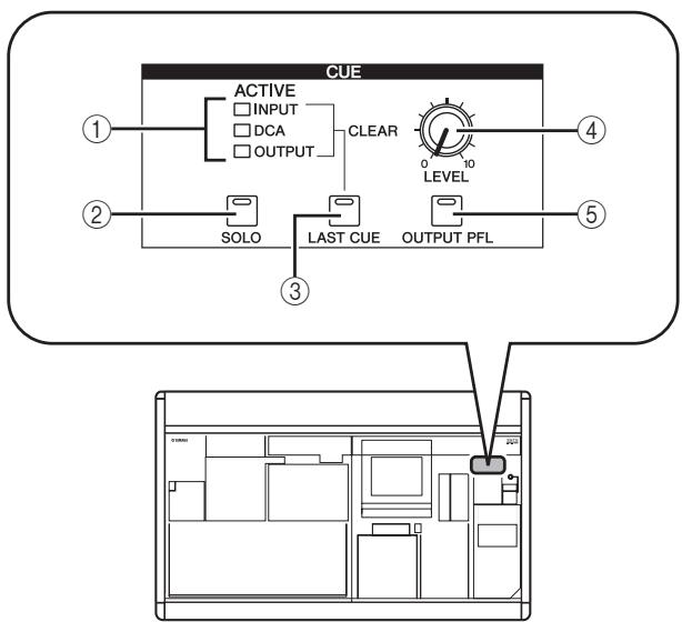
① [INPUT]/[DCA]/[OUTPUT] LEDs
These LEDs indicate the monitoring status. If even one [CUE] key is on, the LED of the group to which that key belongs will light. If a special Cue signal such as KEY IN CUE or EFFECT CUE is active, all three LEDs will light.
② [SOLO] key
This selects how monitoring will occur when you use the [CUE] keys. If this key is on, monitoring will operate in SOLO mode. If this key is off, monitoring will operate in CUE mode.
(3) [LAST CUE] key
This selects the mode of operation when more than one [CUE] key is on. Turning the key on selects LAST CUE mode; turning the key off selects MIX CUE mode. When you switch this mode, Cue will be turned off for all channels.
④ CUE [LEVEL] knob
This adjusts the signal level that is sent from the CUE OUT jacks.
⑤ [OUTPUT PFL] key
This switches the location from which the signal is sent to the CUE bus when you turn on the [CUE] key of an output channel (MIX channel, MATRIX channel, STE-REO A/B channel). If this key is on, the PFL (prefader) signal will be sent. If this key is off, the POST ON (immediately after the [ON] key) signal will be sent.
About CUE mode and SOLO mode
The PM5D lets you select either SOLO mode or CUE mode when using the [CUE] key to monitor signals. Use the [SOLO] key in the CUE section of the panel to switch the mode.
In CUE mode, holding down the [SOLO] key will switch to SOLO mode; the [CUE] keys of all channels will go dark. Conversely in SOLO mode, pressing the [SOLO] key will immediately switch to CUE mode.
These modes differ as follows.
CUE mode
The cue signals of channels / DCA groups whose [CUE] key is on will be sent via the CUE bus and output from the CUE OUT jacks (Cue function). Choose this method when you want to monitor a signal without affecting other channels. When the PM5D is in the default state, the cue signal can also be monitored from the MONITOR OUT jacks.
SOLO mode
Only the channels / DCA groups whose [CUE] key is on will be output from the MIX/MATRIX/STEREO buses, and other channels / DCA groups will be muted (Solo function). The MONITOR OUT jacks also will output only the signal from these same channels / DCA groups.
Note
- If an input channel is soloed, the on/off setting of the output channels will remain unchanged; only the signal of the corresponding input channel will be sent to the buses. If an output channel is soloed, the on/off setting of the input channels will remain unchanged; the signal will be sent only to the corresponding bus.
- If a DCA group is soloed, only the signals of input channels belonging to that DCA group will be output to the corresponding buses. However if output channels are assigned to DCA groups 7/8, signals will be sent only to buses belonging to that DCA group.
Hint
If desired, you can exclude specific channels from Solo operations (→ p.241).
Cue and Solo groups
The PM5D's cue and solo signals can be categorized into the following four groups.
- INPUT CUE group
The cue/solo signals of input channels make up this group. This group becomes active when a [CUE] key of an input channel, ST IN channel, or FX RTN channel is pressed to turn it on.
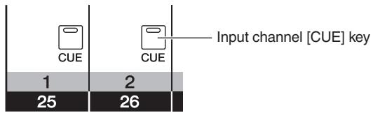
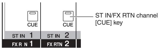
DCA CUE group
The cue/solo signals of DCA groups make up this group. This group becomes active when a [CUE] key in the DCA strip is pressed to turn it on.
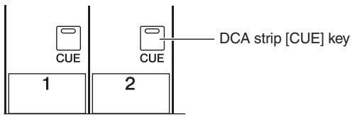
OUTPUT CUE group
The cue/solo signals of output channels make up this group. This group becomes active when a [CUE] key of a MIX channel, MATRIX channel, or STEREO A/B channel is pressed to turn it on.
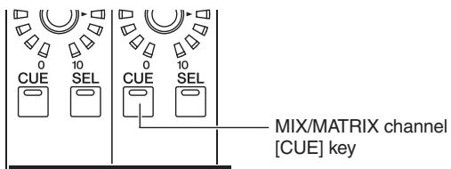
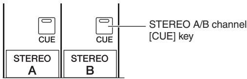
- Other CUE group
This group consists of the cue/solo signals operated by the CUE buttons in the display. This group becomes active when you click to turn on a CUE button in the EFFECT PARAM screen (EFFECT function) or GATE PARAM screen (INPUT GATE/COMP function).

-CUE button in the display
It is not possible to simultaneously turn on Cue between different groups. Normally, the group to which the most recently pressed [CUE] key (CUE button) belongs will take priority, and the [CUE] keys of the previously selected group will be defeated.
However if you have switched cue/solo signal groups in a certain order, the [CUE] key status of the previously selected group will be recovered when you turn off the [CUE] key (CUE button) to defeat the current cue/solo selection.
The [CUE] key status can be recovered for the following combinations of groups.
OUTPUT CUE group DCA CUE group
OUTPUT CUE group INPUT CUE group
DCA CUE group INPUT CUE group
- INPUT CUE / OUTPUT CUE / DCA CUE group Other CUE group
For example if you switch groups in the order of OUTPUT CUE group DCA CUE group INPUT CUE group Other CUE group, you can then successively defeat the [CUE] keys (CUE buttons) to recover the [CUE] key status of the previously selected group.
Using the Cue function
This section explains how you can use the [CUE] key of a desired channel or DCA group to monitor the Cue signal.
Note
If you want the cue/solo signal to be output from the MONITOR OUT jacks as well, access the MONITOR screen (MON/CUE function) and make sure that the CUE INTERRUPTION ON/OFF button is on before you continue with the following procedure ( p.239) .
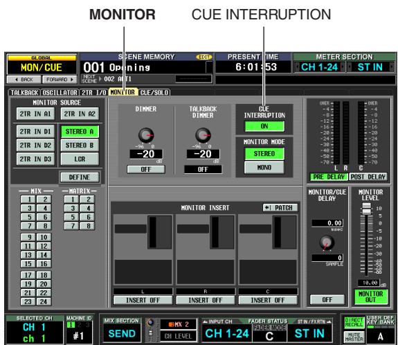
Using the [OUTPUT PFL] key of the CUE section, select one of the following as the output position of the signal sent to the CUE bus when an output channel [CUE] key is pressed.
- PFL ([OUTPUT PFL] key is on)
The signal from immediately before the fader will be sent to the CUE bus. - POST ON ([OUTPUT PFL] key is off)
The signal from immediately after the [ON] key will be sent to the CUE bus.
Hint
The above setting can also be made in the CUE screen (MON/CUE function) ( p.240) . In this screen you can also specify the output position of the signal sent from input channels and DCA groups to the CUE bus.
2 In the CUE section, use the [LAST CUE] key to specify the mode of operation when more than one [CUE] key within the same group is turned on.
LAST CUE mode ([LAST CUE] key is on)
Only the channel/group whose [CUE] key was last turned on will be monitored.
- MIX CUE mode ([LAST CUE] key is off)
Channels/groups within the same group whose [CUE] key is turned on will be monitored.
Note
- [CUE] keys belonging to different groups cannot be turned on simultaneously. The group to which the last-pressed [CUE] key belongs will be turned on, allowing the signals of that group to be monitored.
- If you press the [CUE] key of a paired channel, both channels will be turned on.
3 Make sure that the [SOLO] key in the CUE section is turned off.
4 Press the [CUE] key of a desired channel or DCA group to turn it on.
The cue signal of the corresponding channel will be output from the CUE OUT jacks and the MONITOR OUT jacks.
5 To defeat Cue, press the currently-on [CUE] key once again.
Hint
If you press the [LAST CUE] key to switch from LAST CUE mode to MIX CUE mode (or vice versa), all previously-enabled Cue (Solo) signals will be defeated. For example if you have turned on multiple [CUE] keys in MIX CUE mode, you can quickly turn them all off by pressing the [LAST CUE] key twice.
Using the Solo function
This section explains how to use the Solo function.
1 Use the [LAST CUE] key of the CUE section to specify the mode of operation when a [CUE] key is turned on (LAST CUE mode or MIX CUE mode).
2 In the CUE section, press and hold the [SOLO] key.
When you press and hold the [SOLO] key, the key LED will blink and SOLO mode will be enabled. In SOLO mode, only the signal of the channel or DCA group whose [CUE] key is turned on will be sent to the MIX, MATRIX, and STEREO buses. The same signal can also be monitored from the MONITOR OUT jacks and CUE OUT jacks.
Hint
If desired, you can exclude specific channels or groups from Solo operations (for details, refer to p.241).
3 Turn on the [CUE] key of a desired channel or DCA group.
Only the corresponding channel or DCA group will be output to the buses and output jacks; the remaining channels and DCA groups will be muted. The same signal will also be output from the CUE OUT jacks and the MONITOR OUT jacks.
Note
If you turn on the [CUE] key of an output channel, the signal will be sent only to the corresponding bus.
4 To defeat Solo, press the [SOLO] key.
If you press the [SOLO] key while in SOLO mode, you will immediately return to CUE mode.
Hint
Normally, the Cue/Solo functions can be operated independently of scene memories.
12 Talkback and Oscillator
This chapter explains how to use talkback and oscillator.
About the TALKBACK/OSCILLATOR sections
The TALKBACK and OSCILLATOR sections let you send the signal of a mic connected to the TALKBACK jack or the signal of a test oscillator to the desired output jacks.
Signal flow in the TALKBACK/OSCILLATOR sections is as follows.
PM5D
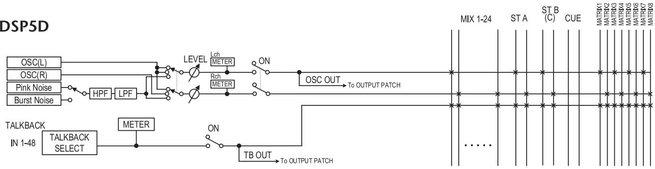
DSP5D
Items in the TALKBACK/OSCILLATOR sections
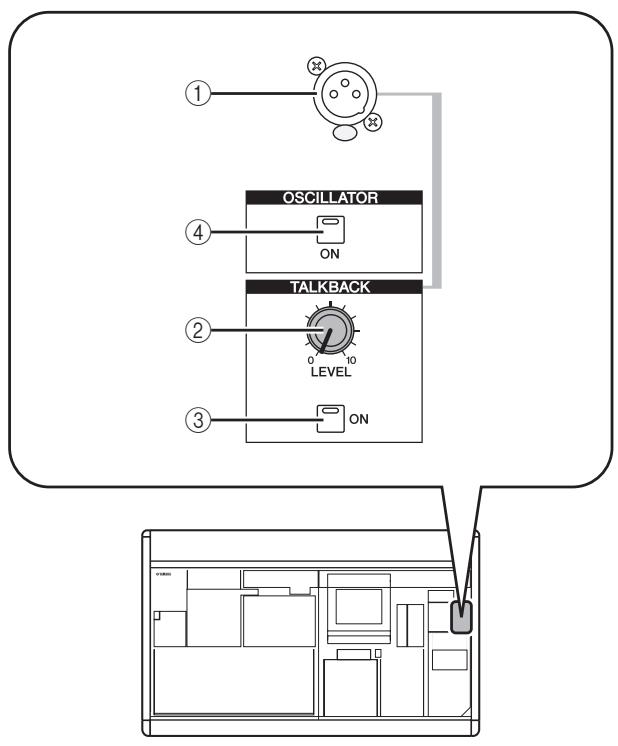
① TALKBACK jack
This is a balanced XLR-3-31 jack to which a talkback mic can be connected. You can make settings in the display to supply +48V phantom power to this jack.
② TALKBACK [LEVEL] knob
This adjusts the input level of the mic connected to the TALKBACK jack.
③ TALKBACK [ON] key
This switches the talkback signal on/off. When you press and hold the key, talkback will be on as long as you hold down the key. If you press and immediately release the key, talkback will remain on until you press the key once again.
However if the NEVER LATCH button is turned on in the TALKBACK screen, talkback will be on only while you hold down the key, and will turn off when you release the key; i.e., talkback will not "latch" even if you press and immediately release the key.
④ OSCILLATOR [ON] key
This is an on/off switch for the signal sent from the internal oscillator to the specified bus(es).
Note
If the OSCILLATOR [ON] key is off, and a screen other than the OSCILLATOR screen (TALKBACK function) is displayed, pressing this key will only display the OSCILLATOR screen; the key will not turn on. When you press the key once again, it will turn on. If the key is on, pressing it once again will turn it off regardless of the screen that is displayed.
Using talkback
Here's how the talkback signal input from the TALKBACK jack can be sent to the desired bus(es).
1 Repeatedly press the [MON/CUE] key of the DISPLAY ACCESS section until the TALKBACK screen appears.
![YAMAHA PM5D-RH - Repeatedly press the [MON/CUE] key of the DISPLAY ACCESS section until the TALKBACK screen appears. - 1](/content/2025/01/115055/images/6802648d2349d07e4f899bd67cb412f50c70725265030f4b70efd7a95ccc6adb.jpg)
Note
If you select the DSP5D when cascade-connected to the DSP5D, the TALKBACK IN field will not be displayed.
2 Turn the TALKBACK [LEVEL] knob to adjust the input sensitivity of the talkback mic.
The meter in the TALKBACK IN area indicates the input level of the mic connected to the TALKBACK jack. If you want phantom power (+48V) to be supplied to the TALKBACK jack, turn on the +48V button located in the TALKBACK IN area.
Hint
The INPUT TO TALKBACK area also lets you use any INPUT jack 1-48 as a supplementary input for talkback.
3 Click a button in the BUS ASSIGN area to specify the bus(es) to which the talkback signal will be sent (multiple selections are allowed).
These buttons correspond to the following buses.
| MIX 1-24 buttons | MIX buses 1-24 |
| MATRIX 1-8 buttons | MATRIX buses 1-8 |
| STEREO AL/R | STEREO A bus L/R channels |
| STEREO BL/R | STEREO B bus L/R channels |
Hint
If desired, the talkback signal can also be output directly from an output channel of slot 1-4 or from 2TR OUT DIGITAL jacks 1-3. To do so, click the PATCH button in the TALKBACK OUT area to access the OUTPUT PATCH screen, and patch talkback to the jack you want to use for direct output.
4 To enable talkback, press the TALKBACK [ON] key in the TALKBACK section of the panel to turn it on.
The TALKBACK [ON] key can operate in either of the following two ways, depending on the setting of the NEVER LATCH button in the TALKBACK area.
- If the NEVER LATCH button is off
Talkback will be switched on/off each time you press the TALKBACK [ON] key (Latched). However if you press and hold down the TALKBACK [ON] key, talkback will remain on only while you continue holding down the key, and will turn off when you release the key (Unlatched).
- If the NEVER LATCH button is on
Talkback will be on only while you continue holding down the TALKBACK [ON] key, and will turn off when you release the key (Unlatched).
Hint
- The TALKBACK [ON] key of the panel and the TALKBACK ON/OFF button in the screen are linked. The setting of the NEVER LATCH button also affects both of these. However if the NEVER LATCH button is off, holding down the on-screen TALKBACK ON/OFF button will cause Latched operation.
- When talkback is on, you can use the talkback dimmer to lower the monitor levels other than talkback ( p.239).
- You can also assign the talkback function to a user-defined key ( p.208).
The PM5D contains a test oscillator. By outputting the oscillator signal to the desired bus you can check the operation of connected devices or test the acoustics of a hall.
1 Repeatedly press the [MON/CUE] key of the DISPLAY ACCESS section until the OSCILLATOR screen appears.
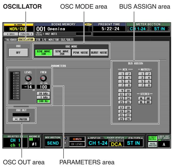
2 Click a button in the OSC MODE section to select the type of oscillator to output, from the following choices.
| SINE WAVE 1CH button | Sine wave x 1 channel |
| SINE WAVE 2CH button | Sine wave x 2 channels |
| PINK NOISE button | Pink noise |
| BURST NOISE button | Burst noise (repeated output of pink noise) |
3 Use the knobs and buttons of the PARAMETERS area to adjust the oscillator parameters.
The parameters that can be adjusted will depend on the type of oscillator you selected in step 2. For example if you selected SINE WAVE 1CH as the oscillator type, the PARAMETERS area will contain the following parameters.
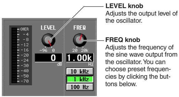
4 Click a button in the BUS ASSIGN area to select the oscillator signal output destination from the following choices.
| MIX 1-24 | MIX buses 1-24 |
| MATRIX 1-8 | MATRIX buses 1-8 |
| STEREO AL/R | STEREO A bus L/R channels |
| STEREO BL/R | STEREO B bus L/R channels |
Hint
- If you selected SINE WAVE 2CH as the oscillator type, the L-channel signal of the oscillator will be sent to odd-numbered buses (or the L output jack) and the R-channel signal of the oscillator will be sent to even-numbered buses (or the R output jack).
- You can use the OSC OUT area to directly output the oscillator signal from an output jack or slot ( p.237).
5 Press the OSCILLATOR [ON] key of the OSCILLATOR section.
The oscillator signal will be sent to the bus you selected in step 4. When you press the key again, the oscillator will turn off.
Hint
The OSCILLATOR [ON] key of the panel and the OSC ON/OFF button in the screen are linked.
Note
If the OSCILLATOR [ON] key is off, and a screen other than the OSCILLATOR screen (TALKBACK function) is displayed, pressing this key will only display the OSCILLATOR screen; the key will not turn on. When you press the key once again, it will turn on.
13 Meters
This chapter explains meter-related operations.
Items in the meter section
The meter section shows the input levels of the input channels and the output levels of the output channels.
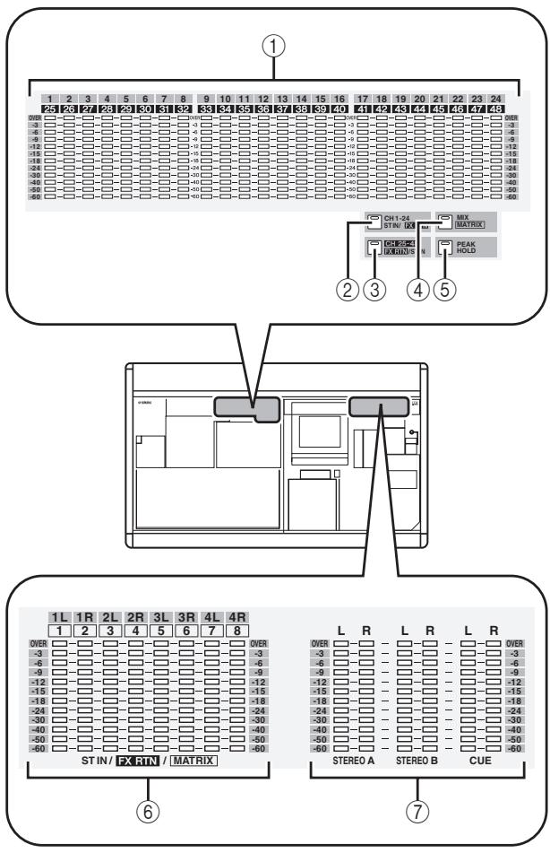
① INPUT/MIX meters
Depending on the key you press, these meters indicate the input levels of input channels 1-24 or 25-48, or the output levels of MIX channels 1-24.
② [CH 1-24/ST IN/FX RTN] key
When this key is on, the INPUT/MIX meters indicate the input levels of input channels 1-24 and the ST IN/ FX RTN/MATRIX meters indicate the output level of ST IN channels (or FX RTN channels, depending on the FOLLOW INPUT LAYER setting) 1-4.
③ [CH 25-48/FX RTN/ST IN] key
When this key is on, the INPUT/MIX meters indicate the input levels of input channels 25-48 and the ST IN/ FX RTN/MATRIX meters indicate the output level of FX RTN channels (or ST IN channels, depending on the FOLLOW INPUT LAYER setting) 1-4.
④ [MIX/MASTER] key
When this key is on, the INPUT/MIX meters indicate the output levels of MIX channels 1-24 and the ST IN/ FX RTN/MATRIX meters indicate the output levels of MATRIX channels 1-8.
(5) [PEAK HOLD] key
Switches the peak hold function on/off for the meter display.
⑥ ST IN/FX RTN/MATRiX meters
Depending on the key you press, these meters indicate the output levels of ST IN channels 1-4 or MATRIX channels 1-8.
⑦ MASTER meters
These meters always indicate the output levels of the STEREO A/B channels and CUE bus.
Switching the meter display
You can use the keys of the meter section to specify the channels whose levels will be shown in the INPUT/MIX meters and ST IN/MATRIX meters. The following channels correspond to each key.
| Key | [INPUT/MIX] meters | [ST IN/MATRIX] meters |
| [CH 1-24/ST IN/FX RTN] key | Input channels 1–24 | ST channels (or FX RTN channels) 1–4 |
| [CH 25-48/FX RTN/ST IN] key | Input channels 25–48 | FX RTN channels (or ST IN channels) 1–4 |
| [MIX/MATRIX] key | MIX channels 1–24 | MATRIX channels 1–8 |
Hint
- The type of channels shown in the meter section is also shown in the METER SECTION area in the upper right of the display.
- The MASTER meters always indicate the output levels of the STEREO A/B channels and CUE bus.
The metering point for the level meters (i.e., the position at which the level is detected) can be specified separately for input channels and output channels.
Specifying the metering point for input channels
Here's how to specify the metering point for input channels and ST IN/FX RTN channels.
1 In the DISPLAY ACCESS section, repeatedly press the [METER] key to access the INPUT METER screen.
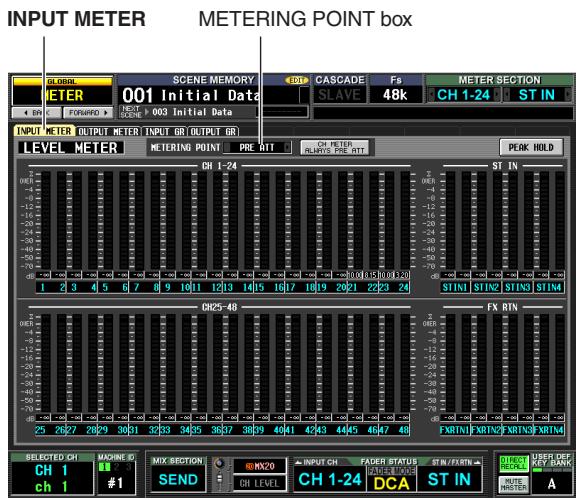
2 Click the / buttons at the left and right of the METERING POINT box to choose one of the following metering points.
| PRE ATT | Immediately before the attenuator |
| PRE GATE | Immediately before the internal gate |
| PRE FADER | Immediately before the fader |
| POST FADER | Immediately after the fader |
| POST ON | Immediately after the [ON] key |
Specifying the metering point for output channels
Here's how to specify the metering point for output channels, MONITOR channels, and the CUE bus.
Hint
The metering point setting for the CUE bus is independent from the other output channels.
1 In the DISPLAY ACCESS section, repeatedly press the [METER] key to access the OUTPUT METER screen.
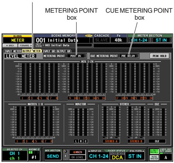
OUTPUT METER
2 To specify the metering point for output channels and MONITOR channels, click the 口 口 buttons at the left and right of the METERING POINT box to choose one of the following.
| PRE EQ | Immediately before the EQ |
| PRE FADER | Immediately before the fader |
| POST FADER | Immediately after the fader |
| POST ON | Immediately after the [ON] key |
| POST DELAY | Immediately after the internal delay |
3 To specify the metering point for the CUE bus, click the l buttons at the left and right of the CUE METERING POINT box to choose one of the following.
| PRE DELAY | Immediately before the internal delay |
| POST DELAY | Immediately after the internal delay |
Viewing the gain reduction of the internal gates and compressors
The amount of gain reduction produced by the gates/compressors of the input channels and the amount of gain reduction produced by the compressors of the output channels can be viewed in the display.
Viewing the gain reduction for input channels
Here's how to view the amount of gain reduction produced by the gates/compressors provided on input channels 1-48 and ST IN channels 1-4.
1 In the DISPLAY ACCESS section, repeatedly press the [METER] key to access the INPUT GR screen.
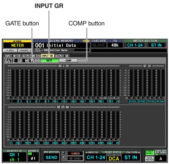
Viewing the gain reduction for output channels
To view the amount of gain reduction produced by the compressors provided on the output channels, repeatedly press the [METER] key of the DISPLAY ACCESS section to access the OUTPUT GR screen.
For an explanation of the items shown in the screen, refer to the explanation of the OUTPUT GR screen ( p.234) in the Reference section.
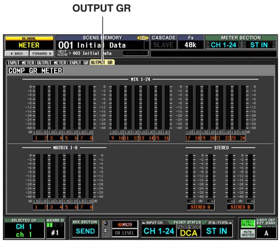
2 Click the GATE button or COMP button to select the parameter that will be displayed.
For an explanation of the items shown in the screen, refer to the explanation of the INPUT GR screen
( p.233) in the Reference section.
14 Effects
This chapter explains the functionality and operation of the PM5D's internal effects.
About the internal effects
The PM5D contains eight internal effect modules. For each module, you can choose one of 55 effect types for the module to use.
Note
The eight effects can also be used as GEQ modules (p.119).
To use an internal effect via send/return, assign the output of a MIX channel to the input of the effect, and assign the output of the effect to an input channel. In this case, the corresponding MIX bus is used as an effect send AUX bus, and the input channel is used as an effect return channel. By default, the L/R outputs of effects 1-4 are assigned to L/ R of FX RTN channels 1-4.
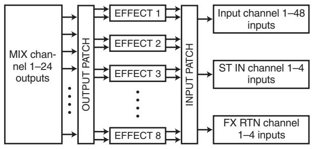
Alternatively, you can insert an internal effect into a channel by assigning the input/output of the internal effect to the insert-out/insert-in of the desired channel.
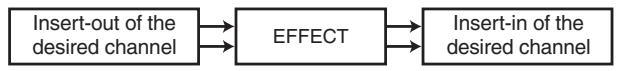
The PM5D's effect types fall into two categories; "stereo effect types" which process the L/R channel input signals independently, and "mix effect types" which mix the two channels before processing the signal.
If signals are assigned to both the L and R inputs of an effect, the way in which the L/R channels are processed will depend on whether a Stereo effect type or a Mix effect type is selected, as follows.
- Stereo effect types
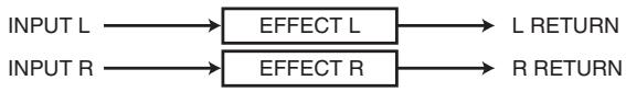
- Mix effect types
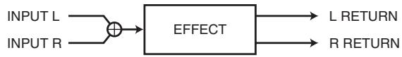
If a signal is assigned to only one input of an effect, it will be processed as mono-in/stereo-out regardless of whether a Stereo effect type or Mix effect type is selected.
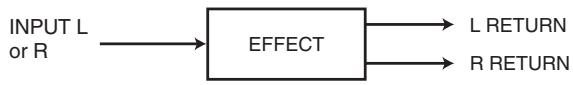
Using an internal effect via a MIX bus
This section explains how to use an internal effect via a MIX bus. As an example, we will choose effect 1 for our operations, assign MIX bus 1 to the effect input, and assign the effect output to FX RTN channels 1/2 .
1 In the DISPLAY ACCESS section, repeatedly press the INPUT [PAN/Routing] key to access the CH to MIX screen.
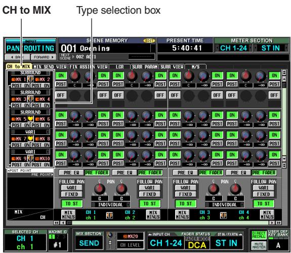
2 Make sure that the MIX bus 1 type selection box indicates "VARI."
If the box indicates "FIXED," click the + / + buttons at left and right to change the indication to "VARI"; then press the [ENTER] key (or click inside the box) to finalize the change.
This box selects the operation of the MIX bus (VARI or FIXED). If VARI is selected, the bus send levels will be adjustable.
Hint
The VAR/FIXED selection is made for two adjacent odd-numbered/even-numbered MIX buses. If the effect input is stereo, it is convenient to pair these two MIX buses.
3 In the DISPLAY ACCESS section, repeatedly press the [EFFECT] key to access the EFFECT PARAM screen.
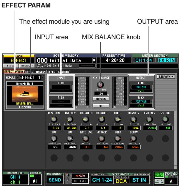
4 Make sure that the box in the upper left of the screen indicates EFFECT 1.
This box lets you select the effect module that you want to control. If a different effect module is selected, click the / buttons at left and right to select EFFECT 1.
Hint
You can access the EFFECT ASSIGN screen (EFFECT function) to see all eight effect modules at once while you assign signal routes to the effect inputs and outputs, or operate Bypass and Cue ( p.168) .
5 In the INPUT area, click the l buttons at the left and right of the L CH box to select MIX 1 (MIX channel 1); then press the [ENTER] key (or click within the box).
This assigns the output of MIX channel 1 to the L input of the effect.
If a signal route is already assigned, a window will appear when you press the [ENTER] key, asking you to confirm the assignment. Click the OK button to confirm the assignment.
If you want to use the effect input in stereo, assign MIX channel 2 to the R CH box in the same way.
6 In the OUTPUT area, make sure that the L CH box indicates FX RTN1L and the R CH box indicates FX RTN1R.
The L CH/R CH boxes in the OUTPUT area select the input channels that are assigned to the L/R outputs of the effect.
By default, the L/R outputs of effect 1 are assigned to FX RTN channel 1 (L/R). If different channels are selected, use the 4 / 5 buttons at the left and right of the boxes to select FX RTN1L and FX RTN1R respectively.
7 Set the MIX BALANCE knob to about 100.
The MIX BALANCE knob adjusts the balance between the original sound and effect sound included in the output signal from the effect. If this knob is at the 100 (%) position, only the effect sound will be output.
8 In the ENCODER MODE section, press the MIX SEND SELECT [1] key to make the encoder mode indicator show "1".
In this state you can use the input channel encoders to adjust the send level from each channel to MIX bus 1.
9 Turn the encoders of the INPUT channel strip and ST IN channel strip to adjust the send level of the signal sent from each channel to MIX bus 1.

Don't raise the encoder of the FX RTN channel you are using as the effect return. Doing so will send the output of the effect back to the input, possibly causing oscillation.
Hint
- The send position of the signals sent from input channels to the MIX bus can be specified for each channel ( p.51).
- As an alternate way to adjust the send level, you can turn on the [MIX SEND] key of the MIX section, then use a [SEL] key to select an input channel and turn the corresponding MIX encoder (→ p.51).
10 In the MIX section, press the [MIX MASTER] key to turn it on (LED lit).
When the [MIX MASTER] key is on, you can use the controls of the MIX section to control MIX channels 1-24.
11 Press the MIX channel 1 MIX [ON] key to turn it on. Use the MIX encoder of that MIX channel to adjust the master send level of the signal sent to the effect.
12 In the FX RTN channel strip, press the FX RTN channel 1 [ON] key to turn it on.
13 Use the FX RTN channel 1 fader to adjust the effect return level.
Hint
The input/output levels of the effect can be viewed in the meters shown in the EFFECT PARAM screen or EFFECT ASSIGN screen.
Inserting an internal effect into a channel
You can insert an internal effect into a channel by assigning the input/output of the internal effect to the insert-out/insert-in of the desired channel. As an example, here's how to insert an effect into an input channel.
1 In the DISPLAY ACCESS section, repeatedly press the [EFFECT] key to access the EFFECT PARAM screen.
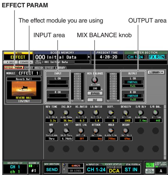
2 To select the effect module you want to use, click the l buttons at the left and right of the box in the upper left of the screen.
3 In the INPUT area, use the 1 / 2 buttons at the left and right of the L CH box to select the insert-out of the channel into which you want to insert the effect, and press the [ENTER] key. (If a signal route has already been assigned, a window will ask you to confirm the assignment change.)
If you are inserting the effect into a stereo channel (or two paired channels), use the R CH box to assign the insert-out for the other channel in the same way.
4 In the OUTPUT area, use the l buttons at the left and right of the L CH box to select the insert-in assigned to the L output of the effect. If you are inserting the effect into a stereo channel (or two paired channels), use the R CH box to assign the insert-in for the other channel in the same way.
5 In the DISPLAY ACCESS section, repeatedly press the INPUT [PATCH] key to access the INSERT/DIRECT OUT POINT screen.
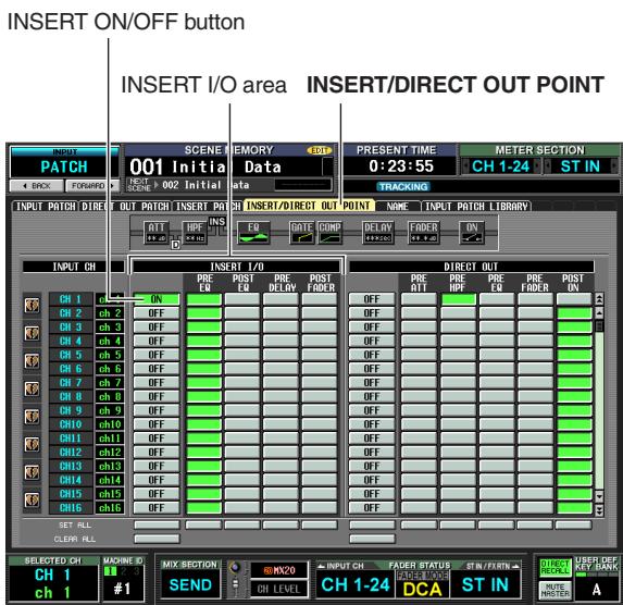
6 Turn on the INSERT ON/OFF button for the channel into which you inserted the effect.
This enables the effect insertion for the corresponding channel.
7 Use the buttons of the INSERT I/O area to specify the insert-out/in point.
Hint
For details on the INSERT I/O area, refer to INSERT/DIRECT OUT POINT screen ( p.281) in the Reference section.
8 Turn on the [ON] key for the channel into which you inserted the effect, and use the fader to adjust the input level.
9 Access the EFFECT PARAM screen, and drag the MIX BALANCE knob to adjust the balance of the effect sound and original sound.
The input/output levels of the effect can be viewed in the meters shown in the EFFECT PARAM screen or EFFECT ASSIGN screen.
Basic operations in the effect screen
This section explains how to store or recall effect library data, and how to edit effect parameters.
Note
Data created by versions earlier than PM5D V2.0 can be loaded into the PM5D V2.0 or the DSP5D. However, you must move library number 55 to number 56 or later before loading. On PM5D version 2.0 or later, library number 55 will be deleted.
Recalling settings from the effect library
Here's how to recall existing settings from the effect library.
1 In the DISPLAY ACCESS section, repeatedly press the [EFFECT] key to access the EFFECT PARAM screen.
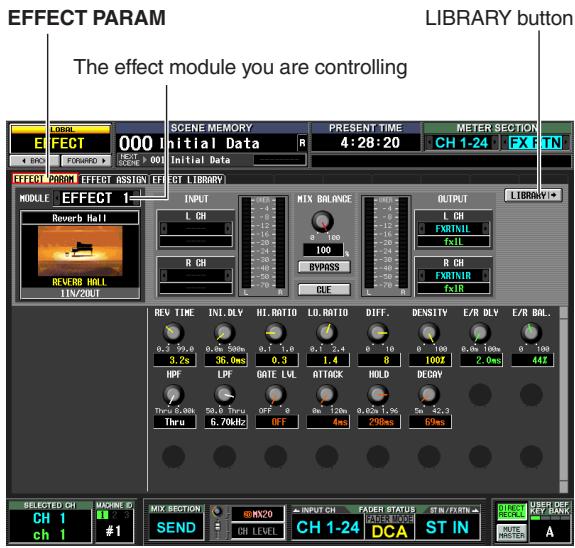
Note
You cannot change the currently selected effect type in the EFFECT PARAM screen. To change the effect type, you must recall (load) a library item that uses the desired effect type.
2 Click the / buttons at the left and right of the box in the left side of the screen to select the effect module you want to use, and then click the LIBRARY button.
The EFFECT LIBRARY screen will appear, allowing you to recall or store settings in the effect library.
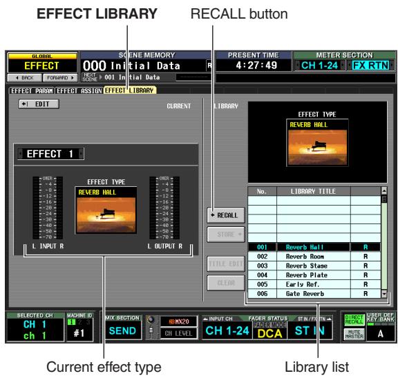
Hint
You can also access this screen by repeatedly pressing the [EFFECT] key. The effect module you are controlling can also be selected in this screen.
3 In the library list at the right of the screen, click to select the library item you want to recall
When you click a library item in the library list, that line will be highlighted and move to the center of the list. The effect type of the currently selected library item will be shown above the library list.
4 Click the RECALL button.
The selected library item will be loaded into the effect module you chose.
Hint
You can click the EDIT button in the upper right of the screen to access the EFFECT PARAM screen for the currently selected effect.
Editing the effect parameters
Here's how to edit the parameters of an internal effect.
1 In the DISPLAY ACCESS section, repeatedly press the [EFFECT] key to access the EFFECT PARAM screen.
The lower part of the screen will show knobs and buttons for editing the parameters of the currently selected effect. The content of the parameters will depend on the type of the currently selected effect.
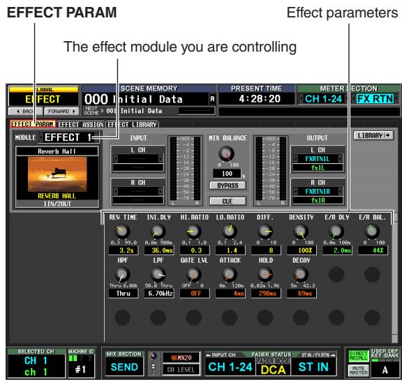
2 Use the box in the upper left of the screen to select the effect module you want to control.
3 Use the knobs and buttons in the lower part of the screen to edit the effect parameters.
For details on the effect parameters, refer to the Appendices at the end of this manual.
Hint
The parameter settings for internal effect modules 1-8 are saved in the scene. The settings of individual effects can also be stored in the effect library independently of scene memory.
Storing settings in the effect library
Here's how to store effect parameter settings in the effect library.
1 In the DISPLAY ACCESS section, repeatedly press the [EFFECT] key to access the EFFECT PARAM screen.
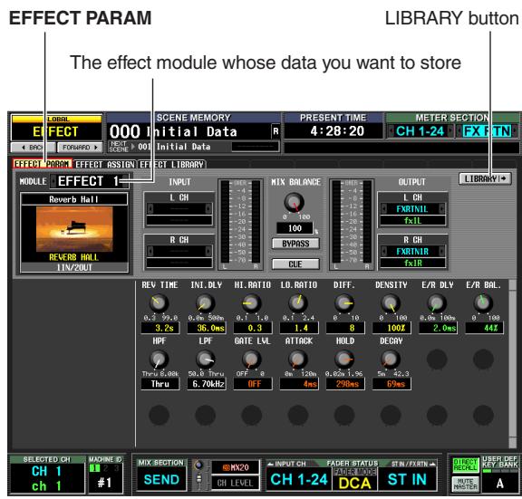
2 Use the box in the upper left of the screen to select the effect module whose settings you want to store, and click the LIBRARY button.
The EFFECT LIBRARY screen will appear, allowing you to recall or store settings in the effect library.
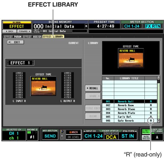
3 In the library list, choose the store-destination number and click that line.
Note
Library items for which an "R" (read-only) appears in the right column of the list are factory preset library items. These numbers cannot be overwritten.
4 Click the STORE button.
The EFFECT LIBRARY STORE window will appear, allowing you to name the library item you are saving.
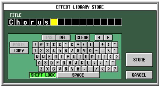
5 Use the character palette to assign a name to the library item.
For details on using the character palette, refer to p.30.
6 Click the STORE button.
A window will ask you to confirm the Store operation.
7 To execute the Store operation, click the OK button.
The data will be stored, and you will return to the previous screen.
If you click the CANCEL button instead of the OK button, the Store operation will be aborted and you will return to the previous screen.
Using the Tap Tempo function
This section explains how to use the Tap Tempo function. "Tap tempo" is a function that lets you specify the delay time of a delay effect or the modulation speed of a modulation effect by striking a key at the desired interval.
1 From the effect library, recall a library item whose effect type uses a TEMPO parameter (e.g., Delay+ER., Echo, Chorus).
TEMPO is a parameter that specifies a time-related effect parameter (the DELAY parameter of Delay+ER, or Echo, or the FREQ. parameter of Chorus, etc.) in terms of a BPM value or a manual setting. The TEMPO parameter is included in delay-type effects or modulation-type effects, and is shown in the lower left of the EFFECT PARAM screen.
Hint
For details on the parameters of each effect type, refer to the Appendices at the end of this manual ( p.325).
2 In the DISPLAY ACCESS section, repeatedly press the [EFFECT] key to access the EFFECT PARAM screen.
The following illustration shows the screen when the "Delay ER." effect type is selected.
EFFECT PARAM
![YAMAHA PM5D-RH - In the DISPLAY ACCESS section, repeatedly press the [EFFECT] key to access the EFFECT PARAM screen. - 1](/content/2025/01/115055/images/f7384086f3383221be43890770a1b5991a84c575d10cac782ec62a548b89c210.jpg)
TAP TEMPO button
3 Move the cursor to the TAP TEMPO button, and repeatedly press the [ENTER] key at the desired tempo. (Alternatively, repeatedly click the TAP TEMPO button.)
The average interval (BPM) at which you press the key will be calculated, and that value will be input for the TEMPO parameter.
![YAMAHA PM5D-RH - Move the cursor to the TAP TEMPO button, and repeatedly press the [ENTER] key at the desired tempo. (Alternatively, repeatedly click the TAP TEMPO button.) - 1](/content/2025/01/115055/images/f591de183959cb9fd5f2a958da861a2c385dbba18119b8babc1c448f77d84e2c.jpg)
The average interval will be input (the average of a, b, and c)
Hint
- The Tap Tempo function is valid only for the currently displayed internal effect. However, it is ignored if the selected effect type does not include a TEMPO parameter.
- If the average value is outside the range of 20–300 BPM, it will be ignored.
- If desired, an external switch connected to the GPI connector can be used to operate the Tap Tempo function of the current page (p.133).
Here's how to use the "FREEZE" effect type, which provides the functionality of a simple sampler. When this effect type is selected, you can perform operations in the screen to record (sample) and play back a sound.
1 In the EFFECT LIBRARY screen, recall a library item that uses the FREEZE effect type.
2 In the DISPLAY ACCESS section, repeatedly press the [EFFECT] key to access the EFFECT PARAM screen.
If the FREEZE effect type is selected, the lower left of the EFFECT PARAM screen will show a REC button, a PLAY button, and a progress bar.
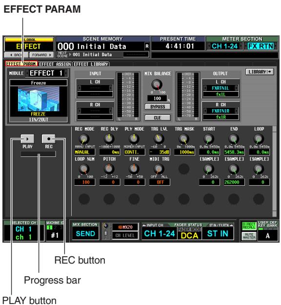
3 To begin recording (sampling), click the REC button and then click the PLAY button.
The signal being input to the effect will be recorded. The progress bar shows the current recording location. When a fixed time has elapsed, the buttons will automatically turn off.
Hint
You can adjust the parameters in the screen to make detailed settings for recording time, the way in which recording will begin, and the way in which the sample will play back. For more about the parameters, refer to the Appendices at the end of this manual ( p.332).
4 To play back the recorded sample, click the PLAY button.
Note
Once you stop, the sampled content will be erased.
15 Graphic EQ and Parametric EQ
The PM5D provides twelve units of 31-band graphic EQ or 8-band parametric EQ (expandable to a maximum of twenty units). This chapter explains how to use the graphic EQ and parametric EQ.
Patching the GEQ modules
The GEQ module built into the PM5D can be inserted into the insert-out/in of the desired channel. As an example, here's how to insert GEQ module into the STEREO A channel.
1 In the DISPLAY ACCESS section, repeatedly press the [GEQ] key to access the GEQ PARAM screen.
In this screen you can select a GEQ module, specify the channel into which it will be inserted, and edit its parameters.
![YAMAHA PM5D-RH - In the DISPLAY ACCESS section, repeatedly press the [GEQ] key to access the GEQ PARAM screen. - 1](/content/2025/01/115055/images/b67ee7827949ce4e31c9b60637e13ad98b1662457b32cf89bab296b16abec1d0.jpg)
2 Click the / buttons at the left and right of the MODULE box in the upper left of the screen to select the GEQ module you want to operate.
3 Click the GEQ/PEQ button located in the upper middle of the screen, to switch between 31-band graphic EQ and 8-band parametric EQ.
4 Click the / buttons at the left and right of the INSERT box to select ST AL [INS] (STEREO A L channel insert-in/out) as the channel into which the GEQ module will be inserted, and press the [ENTER] key (or click within the box). You can choose one of the following insert destinations.
| INS CH 1-INS CH 48 | Input channel 1-48 insert in/out |
| INS STIN1L-INS STIN4R | ST IN channel 1-4 (L/R) insert in/out |
| INS MIX 1-INS MIX 24 | MIX channel 1-24 insert in/out |
| INS MTRX1-INS MTRX8 | MATRIX channel 1-8 insert in/out |
| INS ST AL/INS ST AR | STEREO A channel (L/R) insert in/out |
| INS ST BL-INS ST BR | STEREO B channel insert in/out |
| INS MON L-INS MON C (PM5D only) | MONITOR channel (L/R/C) insert in/out |
If an insert destination is already assigned, a window will appear when you click within the box, asking you to confirm the change. Click the OK button to execute.
5 In the upper left of the screen, click the 4 / 6 buttons at the left and right of the MODULE box to select another GEQ module, and assign it to ST AR [INS] (STEREO A R channel insert-in) in the same way.
6 Click the GEQ ON/OFF button to turn it on. Note
When you insert a GEQ module, the insert-in for the channel will be enabled automatically.
7 In the DISPLAY ACCESS section, repeatedly press the OUTPUT [PATCH] key to access the INSERT POINT screen.
![YAMAHA PM5D-RH - In the DISPLAY ACCESS section, repeatedly press the [GEQ] key to access the GEQ PARAM screen. - 2](/content/2025/01/115055/images/4559d3c4245f85a582978c388b6909a8c058a946e2a6d63aacc76ae8c59db9c2.jpg)
8 If desired, change the insert point for the STE-REO A channel into which you inserted the GEQ module.
When you insert a GEQ module, the insert-in point for that channel will be enabled automatically.
Note
- If you inserted a GEQ module into an input channel, repeatedly press the INPUT [PATCH] key to access the INSERT/DIRECT OUT POINT screen (INPUT PATCH function), and edit the settings in the same way.
- You can also insert a GEQ module into the desired channel's insert-in/out by using the INSERT RET PATCH screen (INPUT PATCH function and OUTPUT PATCH function).
The GEQ modules provided by the PM5D can be expanded to a maximum of 20 modules by re-purposing the eight internal effects.
1 In the DISPLAY ACCESS section, repeatedly press the [GEQ] key to access the GEQ ASSIGN screen.
In this screen, you can view the overall settings and input/output levels for the GEQ modules, specify the signal routing, and turn the module on/off.
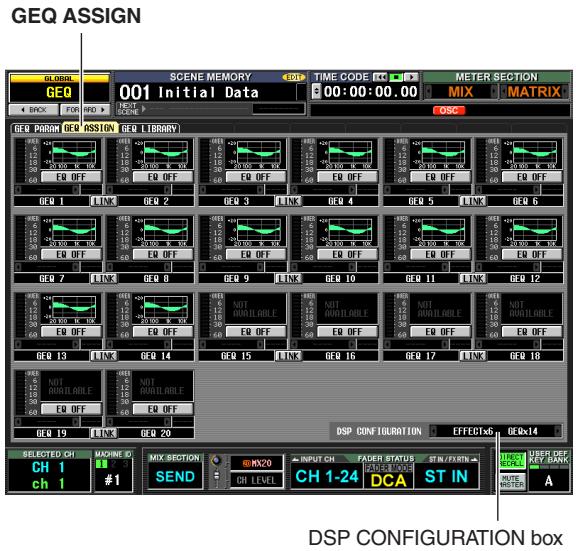
2 In the DSP CONFIGURATION box located in the lower right of the screen, click the left/right / buttons to change the number of internal effects and GEQ modules that will be assigned.
If twelve GEQ modules are used, there will be eight internal effects. If twenty GEQ modules are used, no internal effects will be available.
Basic graphic EQ operations
There are two ways to control a graphic EQ; using the virtual faders and buttons within the display, or using the DCA faders of the panel.
Controlling the graphic EQ from the display
Here's how to control the desired graphic EQ by using the faders and buttons shown in the GEQ PARAM screen (GEQ function).
1 In the DISPLAY ACCESS section, repeatedly press the [GEQ] key to access the GEQ PARAM screen.
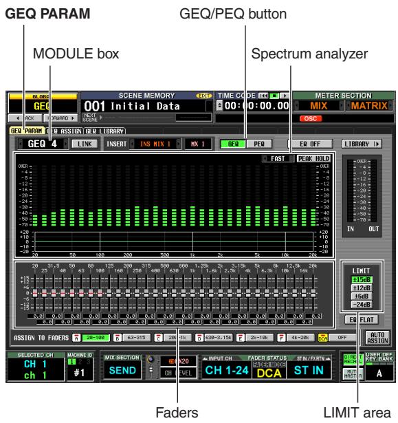
2 Click the / buttons at the left and right of the MODULE box to select the GEQ module you want to operate.
At this time make sure that the GEQ ON/OFF button is on. Also make sure that the corresponding module is inserted into an appropriate channel, and that insert-in/out is enabled for that channel.
Hint
- The upper part of the GEQ PARAM screen functions as a spectrum analyzer. If a signal is being input to the corresponding channel, the level of each frequency band is displayed in realtime.
- As an alternate way to select the desired GEQ module, you can use the GEQ ASSIGN screen (GEQ function) ( p.173) .
3 Click the GEQ button located in the upper middle of the screen to select the 31-band graphic EQ.
4 If desired, use the buttons of the LIMIT area to specify the variable range of the faders.
The LIMIT area lets you select the maximum amount and direction of the change controlled by the faders. You can select ± 15dB / ± 12dB / ± 6dB (both boost and cut directions) or -24dB (cut only).
5 Drag the faders in the lower part of the screen to adjust the amount of boost/cut.
The value of each fader is shown by the box below it.
Hint
Clicking the EQ FLAT button below the LIMIT area will reset all faders to 0 dB.
Controlling the graphic EQ from the DCA section
Here's how to control the graphic EQ using the keys and faders of the panel DCA strip. In this case, the corresponding graphic EQ is divided into six regions for control.
1 In the DISPLAY ACCESS section, repeatedly press the [GEQ] key to access the GEQ PARAM screen.
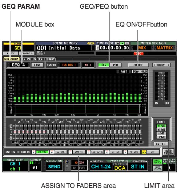
2 Click the / buttons at the left and right of the MODULE box to select the GEQ module you want to operate.
At this time, make sure that the GEQ ON/OFF button is turned on. Also make sure that the corresponding module is inserted into an appropriate channel, and that insert is enabled for that channel.
Hint
When the GEQ PARAM screen is displayed, pressing the [SEL] key of a channel in which a GEQ module is inserted will recall the corresponding GEQ module in the screen.
3 Click the GEQ button located in the upper middle of the screen to select the 31-band graphic EQ.
4 Use the buttons of the LIMIT area to select the maximum amount and direction of the change controlled by the faders.
5 In the lower part of the screen, click a button in the ASSIGN TO FADERS area to select the region you will control from the DCA faders.
The buttons in the ASSIGN TO FADERS area correspond to the following frequency regions.
| A | 20.0-100 button | The eight bands 20.0 Hz-100 Hz |
| B | 63.0-315 button | The eight bands 63.0 Hz-315 Hz |
| C | 200-1.00k button | The eight bands 200 Hz-1.00 kHz |
| D | 630-3.15k button | The eight bands 630 Hz-3.15 kHz |
| E | 2.00k-10.0k button | The eight bands 2.00 kHz-10.0 kHz |
| F | 4.00k-20.0k button | The eight bands 4.00 kHz-20.0 kHz |
When a button is clicked, you can use the DCA faders to control the faders of that frequency region. The faders of the selected region are indicated by a red line in the center of the fader.
While any of the buttons in the ASSIGN TO FADERS area is on, you can use the FADER MODE section FADER MODE [A]-[F] keys to select the frequency region corresponding to these buttons.
Even if all of the buttons in the ASSIGN TO FADERS area are off, you can hold down the [SHIFT] key and press one of the FADER MODE [A]-[F] keys to select the region to be controlled by the DCA faders.
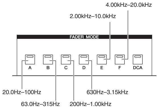
6 Operate DCA faders 1-8.
The corresponding frequency region will be boosted or cut.
Hint
If the fader of a graphic EQ is at the 0 dB position, the [NOMINAL] LED of the DCA fader will light. If it is at other than the 0 dB position, the DCA [MUTE] key will light. While the DCA [MUTE] key is lit, pressing the DCA [MUTE] key will reset the corresponding band to 0 dB.
7 If you want to use the DCA faders to control a different region, repeat steps 5-6.
8 When you have finished using the DCA faders to control the graphic EQ, either press the FADER MODE [DCA] key or click the OFF button in the ASSIGN TO FADERS area.
When the [DCA] button is on, the FADER MODE keys and the DCA faders will return to their normal state. If you once again want to assign the graphic EQ to the DCA faders, either click a button in the ASSIGN TO FADERS area or hold down the [SHIFT] key and press a FADER MODE [A]-[F] key.
Hint
- GEQ module settings are saved as part of the scene. The settings of a GEQ module can also be saved in the GEQ library. For details, refer to GEQ LIBRARY screen (▶ p.174) in the Reference section.
- When you switch the display to a different screen, the DCA fader assignments will be forcibly defeated, and will no longer function even if you return to the GEQ screen. However if you turn on the AUTO ASSIGN button in the GEQ PARAM screen, the DCA faders will automatically be assigned to the most recently operated region when you access the GEQ PARAM screen.
Basic parametric EQ operations
There are two ways to operate the parametric EQ: using the knobs and buttons in the display, or using the SELECTED CHANNEL section of the panel.
Controlling the parametric EQ from the display
Here's how to use the knobs and buttons of the GEQ PARAM screen (GEQ function) to operate the desired parametric EQ.
1 In the DISPLAY ACCESS section, repeatedly press the [GEQ] keys to access the GEQ PARAM screen.
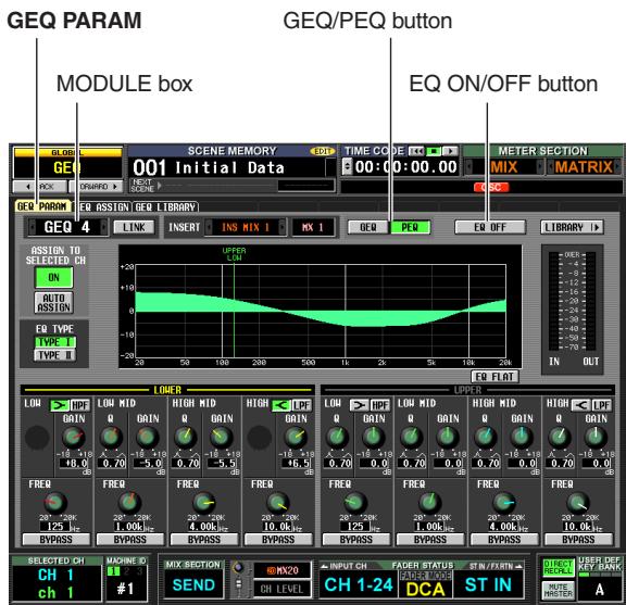
2 In the MODULE box, click the left/right /按钮 to select the GEQ module that you want to operate.
Make sure that the EQ ON/OFF button is on. Also make sure that the corresponding module is inserted into the appropriate channel, and that insert in/out is enabled for that channel.
Hint
An alternate way to select the desired GEQ module is to use the GEQ ASSIGN screen (GEQ function) ( p.173) .
3 Click the PEQ button located in the upper middle of the screen to select the 8-band parametric EQ.
4 If you want to use the LOW band or HIGH band as a shelving-type EQ or as a high-pass or low-pass filter, click the < button of that band, or the HPF/LPF button to turn it on.
If you switch to a shelving type, the Q knob will disappear. When you switch to a high-pass or low-pass filter, the Q knob will disappear, and the GAIN knob will change to the HPF/LPF on/off switch.
5 Using the Q knob, GAIN knob, and FREQ knob of each band, specify the steepness, gain, and center frequency for each band.
The value of each setting is shown in the box below.
Hint
If you click the EQ FLAT button, the boost/cut amount of all bands will be reset to 0 dB.
Controlling the parametric EQ from the SELECTED CHANNEL section
You can use the keys and encoders in the SELECTED CHANNEL section of the panel to operate the parametric EQ.
1 In the DISPLAY ACCESS section, repeatedly press the [GEQ] keys to access the GEQ PARAM screen.
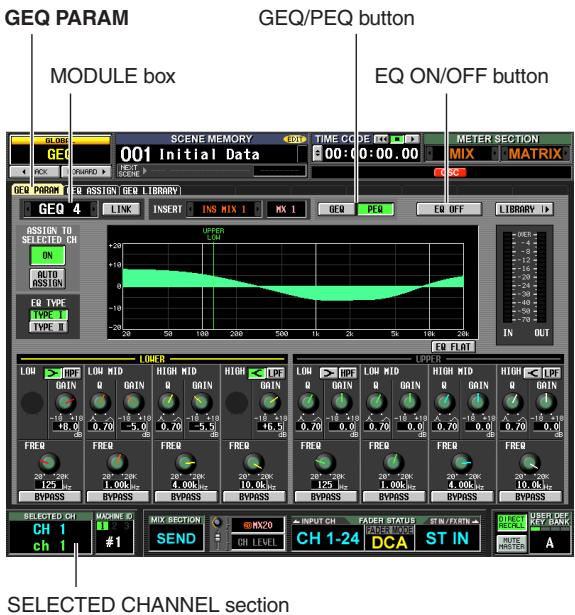
2 In the MODULE box, click the left/right /按钮 to select the GEQ module that you want to operate.
Make sure that the EQ ON/OFF button is on. Also make sure that the corresponding module is inserted into the appropriate channel, and that insert in/out is enabled for that channel.
Hint
If the GEQ PARAM screen is displayed, pressing the [SEL] key of the channel in which the GEQ module is inserted will recall the corresponding GEQ module to the screen.
3 Click the PEQ button located in the upper middle of the screen to select the 8-band parametric EQ.
4 Click the ASSIGN TO SELECTED CH field ON button to turn it on.
5 Use the SELECTED CHANNEL section EQUALIZER controls to control the parametric EQ.
At this time you won't be able to operate the SELECTED CHANNEL section other than EQUALIZER. For details on using the SELECTED CHANNEL section, refer to p.65.
Hint
- GEQ module settings are saved as part of the scene. You can also save desired GEQ module settings in a library. For details, refer to the Reference section GEQ LIBRARY screen (▶ p.174).
- When the display switches to another screen, the UPPER or LOWER assignments are forcibly defeated, and you won't be able to operate this even if you once again access the GEQ PARAM screen. However if you leave the ASSIGN TO SELECTED CH field's AUTO ASSIGN button on, the previously-operated band will automatically be assigned to the SELECTED CHANNEL section when you access the GEQ PARAM screen.
16 Remote control
This chapter explains how you can use MIDI or GPI to control the PM5D's parameters from an external device, or conversely how you can use the PM5D to control external devices.
MIDI on the PM5D
The PM5D can use MIDI to perform the following operations.
- Program Change transmission and reception When you execute a specific event (scene/effect library recall) on the PM5D, a program change message of the corresponding number can be transmitted to an external device. Conversely, the corresponding events can be executed when program change messages are received from an external device.
-
Control Change transmission and reception When you execute a specific event (fader/encoder or key operation) on the PM5D, a control change message of the corresponding number can be transmitted to an external device. Conversely, events can be executed when control change messages are received from an external device. This capability can be used to record fader and key operations on a MIDI sequencer or other external device, and play back this data later. System exclusive messages can also be used to transmit or receive bulk data (scene or library content) or parameters.
-
MIDI Remote function
- You can assign MIDI messages to the controls of the INPUT/ST IN channel strip, and transmit those MIDI messages by operating the controls. This capability can be used for remote control of external MIDI devices such as synthesizers, or to control the parameters of DAW software or a HDR unit.
- MIDI Event transmission MIDI messages can be registered independently for each scene in scene memory, and transmitted when that scene is recalled.
Note
For each of the above functions, the MIDI port used to transmit/receive MIDI messages can be selected from the rear panel MIDI IN/OUT connectors, the rear panel USB connector, and an I/O card installed in slots 1 through 4. (If the USB connector or an I/O card is selected, you can additionally choose from ports 1 through 8.) However, MIDI Event transmission is fixed at the MIDI OUT connector.
Using program changes to control events
The PM5D lets you assign specific events (scene recall / effect library recall) to each MIDI program number, so that the correspondingly-numbered program change message will be transmitted to an external device when you execute that event on the PM5D. Conversely, the corresponding event can be executed when a program change message is received from an external device.
1 Connect the MIDI OUT connector of the external device to the PM5D's MIDI IN connector. Connect the MIDI OUT connector of the PM5D to the MIDI IN connector of the external device.
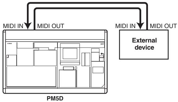
2 In the DISPLAY ACCESS section, press the [MIDI/REMOTE] key several times to access the MIDI PGM CHANGE screen shown below.
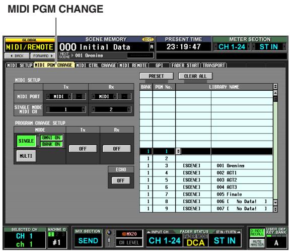
In the MIDI PGM CHANGE screen you can assign events to each program number, select the port at which MIDI messages will be transmitted and received, and select how program changes will be transmitted and received.
3 In the PROGRAM CHANGE SETUP area at the left of the screen, you can select the way in which program changes will be transmitted and received, and switch reception and transmission on/off.
The MODE area of PROGRAM CHANGE SETUP lets you choose one of the following as the way in which program changes will be transmitted and received.
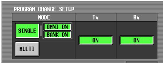
- SINGLE
If this button is on, program changes will be transmitted/received on a single MIDI channel (Single mode).
- OMNI ON/OFF
If this button is on, program changes of all MIDI channels will be received in Single mode (this is unavailable in Multi mode).
BANK ON/OFF
If this button is on, bank select messages will be transmitted and received in Single mode (this is unavailable in Multi mode).
- MULTI
If this button is on, program changes will be transmitted/received on multiple MIDI channels (Multi mode). You can use the Tx (transmission) and Rx (reception) buttons to turn program change transmission and reception on/off separately.
4 In the MIDI SETUP area at the upper left of the screen, select the port at which program changes will be transmitted/received, and the MIDI channel that will be used for transmission and reception. You have the following choices.
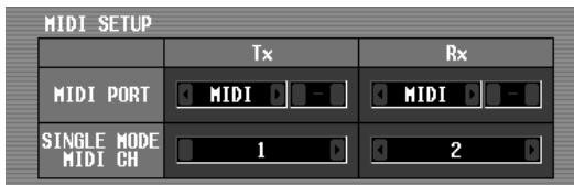
| MIDI | The rear panel MIDI IN/OUT connectors |
| USB | The rear panel USB connector |
| SLOT 1-4 | An I/O card installed in rear panel slot 1-4 |
Click the 1 / 2 buttons at the left and right of the Tx box (transmission) or Rx box (reception) to change the setting, and press the [ENTER] key (or click within the box) to finalize the setting. If you select USB or SLOT 1-4, use the box at the right to specify the port number (1-8) as well.
If SINGLE (single mode) is selected as the program change transmission/reception mode, use the MIDI CH field to select the MIDI transmit channel and MIDI receive channel.
Hint
The MIDI port and MIDI channel used for program change transmission/reception can also be specified from the MIDI SETUP screen (p.188).
5 In the list at the right side of the screen, display the MIDI channel (bank) and program number to which you want to assign an event, and click that line.
This list lets you select the event (scene recall / effect library recall) assigned to each program number.
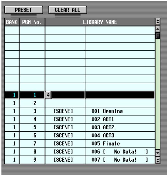
The list contains the following columns.
- CH/BANK (Channel/Bank)
In Multi mode, or in Single mode when the BANK ON/OFF button is off, the value in this column indicates the MIDI channel on which program changes are transmitted and received.
In Single mode when the BANK ON/OFF button is on, the value in this column indicates the bank number.
- PGM No. (Program number)
Indicates the program number 1-128.
- LIBRARY NAME
In this column you can view/select the type and the number of the event assigned to each channel (bank)/ program number.
Use the scroll bar at the right to display the desired channel (bank) and program number, and click that line; the line you click will move to the center and will be highlighted.
6 Click the button in the LIBRARY NAME column of the currently selected line to open the MIDI PGM CHANGE window.
In this window you can select the type of event (a scene, or a library item for effect 1-8) and its number.
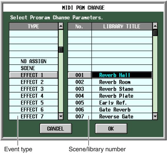
In the list at the left, select the type of event. In the list at the right, select the scene/library number that will be recalled. The following types of event can be selected in the list at the left.
| NO ASSIGN | No event is assigned |
| SCENE | Scene memory recall |
| EFFECT 1-8 | Recall an effect library item into an internal effect module 1-8 |
7 When you have finished making settings, click the OK button in the MIDI PGM CHANGE window.
8 Assign events to other program numbers in the same way.
With these settings, executing the specified event on the PM5D will cause a program change (or bank select + program change) message to be transmitted to the external device.
When an external device transmits a program change (or bank select + program change) message on the appropriate channel, the event assigned to that program number will be executed.
Hint
- You can use the CLEAR button above the list to erase all assignments to program numbers. The PRESET button will return all program number assignments to their default state.
- The contents of the program change table are not saved in the scene. If desired, you can save this data on a memory card as a MIDI PGM TABLE.
Note
If more than one program number is assigned to a single scene, only the lowest-numbered program change will be transmitted in Single mode, and in Multi mode the lowest-numbered program change for each channel will be transmitted.
Using control changes to control events
You can use MIDI control change messages to control specified events (fader/encoder operations, key on/off operations etc.) on the PM5D. This capability can be used to record fader and key operations on a MIDI sequencer or other external device, and play back this data later.
You can use control changes to control events in either of the following two ways.
Using control change numbers 1-119
This method uses the common variety of control change messages. You can freely assign an event to each control number.
- Using NRPN (Non Registered Parameter Number)
This method uses a special type of control change messages called NRPN. NRPN uses control change numbers 99 and 98 to specify the MSB (Most Significant Byte) and LSB (Least Significant Byte) of the parameter number, and subsequently-transmitted control change messages of control change number 6 (or 6 and 38) to specify the value of that parameter.
The event specified by each combination of MSB and LSB is fixed.
1 Connect the MIDI OUT connector of the external device to the PM5D's MIDI IN connector. Connect the MIDI OUT connector of the PM5D to the MIDI IN connector of the external device.
2 In the DISPLAY ACCESS section, press the [MIDI/REMOTE] key several times to access the MIDI CTRL CHANGE screen shown below.
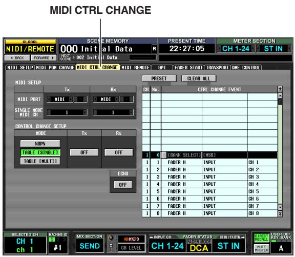
In the MIDI CTRL CHANGE screen you can select the port used to transmit/receive MIDI messages, and how control changes will be transmitted and received. If control change 1-119 is selected as the transmission/ reception method, you can assign the desired event to each control number.
3 In the CONTROL CHANGE SETUP area at the left of the screen, you can select the way in which control changes will be transmitted and received, and switch reception and transmission on/off.
The MODE area of CONTROL CHANGE SETUP lets you choose one of the following as the way in which control changes will be transmitted and received.
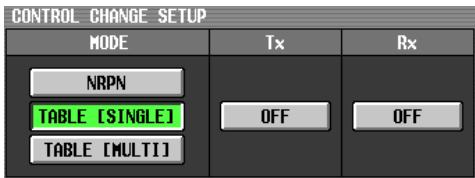
| NRPN | If this button is on, PM5D parameters will be transmitted/received as NRPN messages. |
| TABLE [SINGLE] | If this button is on, PM5D parameters will be transmitted/received as control change messages on a single MIDI channel according to the assignments in the list at the right side of the screen. |
| TABLE [MULTI] | If this button is on, PM5D parameters will be transmitted/received as control change messages on multiple MIDI channels according to the assignments in the list at the right side of the screen. |
You can use the buttons in the Tx (transmission) area and Rx (reception) area to turn control change transmission/reception on/off.
4 In the MIDI SETUP area at the upper left of the screen, select the port used to transmit/ receive control changes, and the MIDI channel used for transmission and reception.
In MIDI SETUP, the MIDI PORT settings let you select the port used for MIDI control change transmission/ reception; you have the following choices.
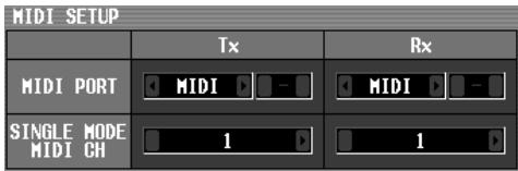
| MIDI | The rear panel MIDI IN/OUT connectors |
| USB | The rear panel USB connector |
| SLOT 1-4 | An I/O card installed in rear panel slot 1-4 |
Click the 1 buttons at the left and right of the Tx box (transmission) or Rx box (reception) to change the setting, and press the [ENTER] key to finalize the setting. If you select USB or SLOT 1-4, use the box at the right to specify the port number (1-8) as well.
If TABLE [SINGLE] or NRPN are selected as the control change transmission/reception method, use MIDI CH field to choose the MIDI channel used for transmission and reception.
Hint
The MIDI port and MIDI channel used for control change transmission/reception can also be specified from the MIDI SETUP screen (p.188).
5 If TABLE [SINGLE] or TABLE [MULTI] are selected as the control change transmission/ reception method, use the list in the right of the screen to display the MIDI channel and control number to which you want to assign an event, and click that line.
In this list you can select the event (fader/encoder operation, key operation, etc.) that will be assigned to each control number. The list contains the following columns.
- CH (Channel)
Indicates the MIDI channel on which the control change is transmitted/received.
Note
You can use this column to specify multiple MIDI channels even if TABLE [SINGLE] is selected as the transmission/ reception method. However in actuality, only the MIDI transmit/receive channel selected in the MIDI SETUP field will be valid.
- CTRL No. (Control number)
Indicates the control number 1-119. You cannot make settings for numbers 0, 32, or 96-101.
- CTRL CHANGE EVENT (Library name)
Indicates/selects the type of event assigned to the corresponding channel / control number.
Use the scroll bar at the right to display the desired channel and control number, and click that line; the line you click will move to the center and will be highlighted.
6 Click the button in the CTRL CHANGE EVENT column of the currently selected line to open the MIDI CTRL CHANGE window, and specify the parameter that you want to assign.
In this window you can specify the parameter in three levels (mode, parameters 1/2).
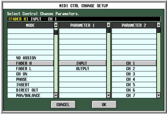
7 When you have finished making settings, click the OK button in the MIDI CTRL CHANGE window.
8 Assign events to other control numbers in the same way.
When you operate the parameters you assigned on the PM5D, control change messages will be transmitted to external devices.
Similarly, if the corresponding control change messages are sent from an external device on the appropriate channel, the parameters assigned to those control numbers will change.
Hint
- You can use the CLEAR button above the list to erase all assignments to control numbers. The PRESET button will return all control number assignments to their default state.
- The contents of the control change table are not saved in the scene. If desired, you can save this data on a memory card as a MIDI CTRL TABLE.
Using the MIDI Remote function
"MIDI Remote" allows you to assign MIDI messages to the controllers (faders, encoders, CH [ON] keys, ENCODER [ON] keys) of the INPUT/ST IN channel strips so that these MIDI messages will be transmitted when you operate these controllers. This capability can be used for remote control of external MIDI devices such as synthesizers, or to control the parameters of DAW software or a HDR unit.
While the MIDI Remote function is active, INPUT channel strip 1-24 functions as MIDI remote channels 1-24, and ST IN channel strip 1-4 functions as MIDI remote channels 25-28.
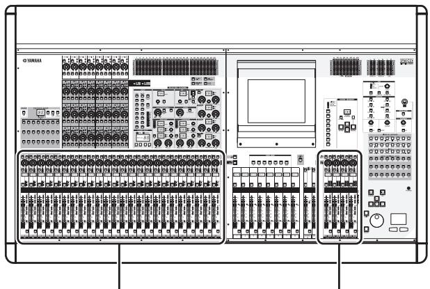
MIDI remote channels 1-24
MIDI remote channels 25-28
To each controller you can assign a MIDI message consisting of up to sixteen bytes of hexadecimal data. If desired, you can specify that a value within the message varies according to the movement of the controller.
Assigning MIDI messages to controllers
Here's how to specify the MIDI port used by the MIDI Remote function, and assign a MIDI message to the desired MIDI remote channel.
1 In the DISPLAY ACCESS section, press the [MIDI/REMOTE] key several times to access the MIDI SETUP screen shown below.
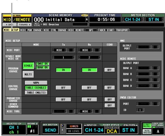
MIDI SETUP
2 In the MIDI REMOTE area at the right of the screen, select one of the following as the port from which MIDI messages will be output for each of the four MIDI Remote banks (BANK A-D).
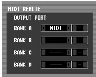
| MIDI | The rear panel MIDI OUT connector |
| USB | The rear panel USB connector |
| SLOT 1-4 | An I/O card installed in rear panel slot 1-4 |
Click the 1 / 2 buttons at the left and right of each box to change the setting, and press the [ENTER] key (or click within the box) to finalize the setting. If you select USB or SLOT 1-4, use the box at the right to specify the port number (1-8) as well.
3 In the DISPLAY ACCESS section, press the [MIDI/REMOTE] key several times to access the MIDI REMOTE screen shown below.
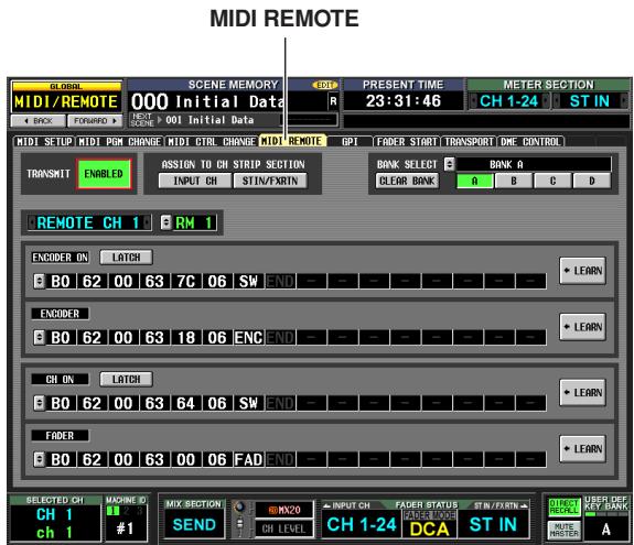
4 In the BANK SELECT area at the upper right of the screen, use the A-D buttons to select the bank you want to use.
The bank name is displayed above buttons A-D. You can change the name by clicking the button at the left of the bank name.
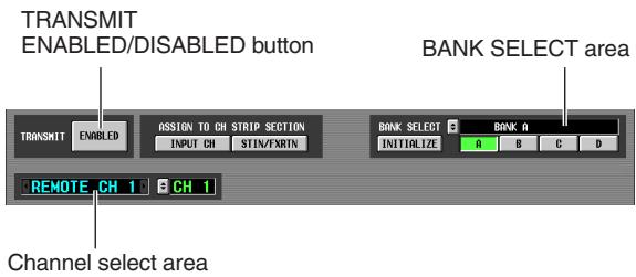
5 In the upper left of the screen, set the TRANSMIT ENABLED/DISABLED button to ENABLED.
Transmission will be enabled for the selected bank. (You can enable/disable transmission for each of the four banks.)
6 Use the channel select area at the left of the screen to select the MIDI remote channel to which you want to assign a MIDI message.
These buttons correspond to the following channel strips.
| REMOTE CH 1-24 | INPUT channel strip 1-24 |
| REMOTE CH 25-28 | ST IN channel strip 1-4 |
When you click the 1 / 2 buttons at the left and right of the box, the corresponding name is displayed in the box at the right. You can change the name of the MIDI remote channel by clicking the 3 button of the box at right.
7 Use the MIDI message boxes in the lower part of the screen to specify a MIDI message for each controller of the channel.
The lower part of the MIDI REMOTE screen contains MIDI message boxes that let you assign a MIDI message to the ENCODER [ON] key, encoder, CH [ON] key, and fader.
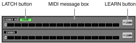
You can assign a MIDI message to a controller in any of the following three ways.
① Directly inputting hexadecimal values In this method you directly input the message as hexadecimal values. To use this method, click the button at the left edge of the desired MIDI message box to open the MIDI REMOTE SETUP window.
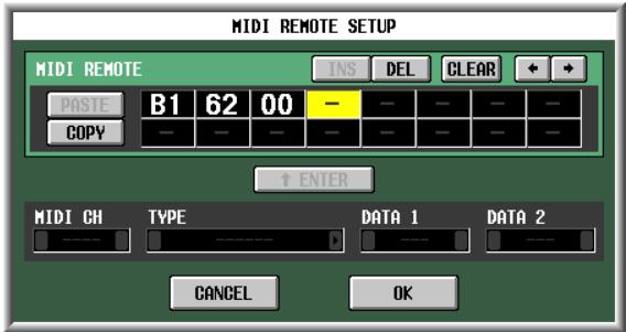
In this window you can input a message by clicking the desired input box to select it (the box will be highlighted) and turning the [DATA] encoder. You can use the [INC]/[DEC] keys to move the selected position. You can input the following values.
| Value | Available assign-ments | Content |
| 00(H)-FF(H) | All | The MIDI message that is transmitted (hexadecimal). |
| END | All | Indicates the end of the MIDI message. When you operate the corresponding controller, the MIDI message from the beginning until immediately before END will be transmitted. |
| SW | All | Indicates the on/off status of the encoder [ON] key or the channel [ON] key. A value of 7F(H) is transmitted when the key turns on, and a value of 00(H) is transmitted when the key turns off. If this is assigned to an encoder or fader, the current value of the key will be transmitted when the encoder or fader is operated. |
| ENC | ENCODER ON/ENCODER | Indicates the current position of the encoder. If assigned to an encoder, a value of 00-7F(H) is transmitted when the encoder is operated. If assigned to an encoder [ON] key, the current value of the encoder is transmitted when the key is switched on. |
| FAD | CH ON/FADER | Indicates the current position of the fader. If the message is assigned to a fader, this value is transmitted as a value of 00-7F(H) when the fader is operated. If assigned to a CH [ON] key, the current value of the fader is transmitted when the key is switched on. |
If you set a value to SW, ENC, or FAD, that value will be linked to the state of the controller. For example if you have made settings as shown in the following screen, the last value will be linked with the fader position, and will change in the range of 0-127.
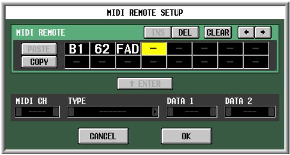
When you click a box in which a hexadecimal value has been input, the range of values that can be interpreted as a valid MIDI message (including that box) will turn red. The lower part of the screen shows the MIDI channel (MIDI CH), message type (TYPE), and data values (DATA 1, DATA 2) for this MIDI message, letting you verify that the appropriate MIDI message has been input.
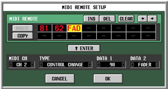
You can use the following buttons to input or edit the message in this window.
| + + buttons | Move the highlighted area to left or right. |
| INS button | Inserts a space (blank) at the highlighted position. Pressing the <Insert> key of a PS/2 keyboard will produce the same result. |
| DEL button | Deletes the character at the highlighted position. Pressing the <Delete> key of a PS/2 keyboard will produce the same result. |
| CLEAR button | Erases the entire message that was input in the MIDI message input boxes. |
| PASTE button | Pastes the message that was copied to buffer memory by the COPY button. |
| COPY button | Copies the message from the MIDI message input box to temporary buffer memory. Use this in conjunction with the PASTE button to copy a message from one controller to another bank or controller. |
When you have finished inputting data in the MIDI REMOTE SETUP window, click the OK button. The hexadecimal values will be input in the MIDI message box of the MIDI REMOTE screen.
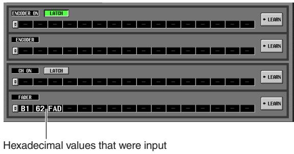
(2) Specifying the type of message
In this method you specify the desired MIDI channel, type of message, and data value; these will be converted into the appropriate hexadecimal values. Access the MIDI REMOTE SETUP window in the same way as for method ①, and click the first box into which you want to input data.
Next, click the 1 / 2 buttons at the left and right of the TYPE box to select the type of message.
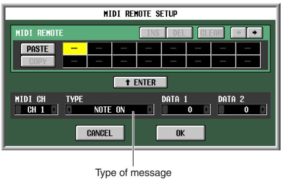
Then use the MIDI CH, DATA 1, and DATA 2 boxes to specify the MIDI channel and various values. The values that can be selected in the MIDI CH, DATA 1, and DATA 2 boxes will depend on the type of message you selected first.
| TYPE | MIDI CH | DATA 1 | DATA 2 |
| NOTE OFF | 1-16 | Note number (0-127) | Note-off velocity (0-127) |
| NOTE ON | Note-on velocity (0-127) | ||
| KEY PRES- SURE | Pressure value (0-127) | ||
| CONTROL CHANGE | Control num- ber (0-127) | Controller value (0-127) | |
| PROGRAM CHANGE | Program number | — | |
| CHANNEL PRESSURE | Pressure value (0-127) | ||
| PITCH BEND | Pitch bend MSB (0-127) | Pitch bend LSB (0-127) | |
| EXCLUSIVEMESSAGE | — | ||
If you set the DATA 1 or DATA 2 value to SWITCH, ENCODER (available only for encoders), or FADER (available only for faders), that value will be linked with the state of the controller.
When you have specified all of the values, click the
" ENTER" button in the screen; the hexadecimal values for that message will be input in the input box of the MIDI REMOTE SETUP window. As necessary, you can edit the message by clicking an input box and turning the [DATA] encoder.
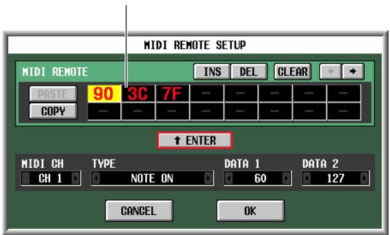
Hexadecimal values that were input
③ Using the LEARN button
The LEARN button lets you assign a MIDI message to a controller by receiving that message from an external device. To use the Learn function, go to the MIDI REMOTE screen and click the LEARN button in for the controller to which you want to assign a message.
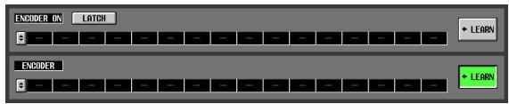
Note
- Only one LEARN button can be turned on simultaneously.
- The LEARN button is valid only for the MIDI remote channel that is currently selected. Also, you cannot change the MIDI remote channel while this button is on.
- The LEARN button is turned off automatically when you switch to a different screen.
If a MIDI message is received at a MIDI port available for the current bank while the LEARN button is on, the received message will be input to the MIDI input box. The following screen shows an example of when the modulation wheel (control change #1) of a synthesizer is operated.
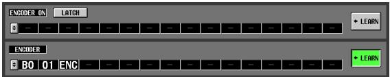
Hint
- MIDI messages assigned using the LEARN button can be a maximum of 16 bytes long (the 17th and subsequent bytes are discarded). If the message is less than 16 bytes long, END will be placed immediately after the last data value.
- If a control change is received, the third byte will automatically be replaced by FAD (if the assignment destination is a fader), ENC (if the assignment destination is an encoder), or SW (if the assignment destination is an encoder [ON] or CH [ON] key).
- If multiple messages are received while the LEARN button is on, the last-received message will be used. If the status byte is omitted from the last message, the appropriate status byte will be supplied.
8 Assign messages to other MIDI remote channels or other banks in the same way.
If a specific byte is set to "SW" for the ENCODER [ON] key or CH [ON] key, use the LATCH button to select one of the following behaviors.
- If the LATCH button is on
The on/off status will change each time you press the key (Latched). If you press the key from the Off state, a MIDI message with 7F(H) as the SW value will be transmitted, and when you press the same key once again a MIDI message with 00(H) as the SW value will be transmitted.
- If the LATCH button is off
The switch will be on only while you are holding it down, and will turn off when you release it (Unlatched). The moment you press the key, a MIDI message with 7F(H) as the SW value will be transmitted; the moment you release the key, a MIDI message with a SW value of 00(H) will be transmitted.
If a specific byte is set to "ENC" (or "FAD") for the ENCODER [ON] key or CH [ON] key, use the LATCH button to select one of the following behaviors.
- If the LATCH button is on
If you press the key from the Off state, a MIDI message with the current value of the encoder (or fader) as the ENC (or FAD) value will be transmitted, and when you press the same key once again a MIDI message with 00(H) as the ENC (or FAD) value will be transmitted.
- If the LATCH button is off
The moment you press the key, a MIDI message with the current value of the encoder (or fader) as the ENC (or FAD) value will be transmitted, and the moment you release the key a MIDI message with 00(H) as the ENC (or FAD) value will be transmitted.
Note
If SW/ENC/FAD are not specified as the last byte of the MIDI message, the same MIDI message will be transmitted when the key is turned on or off. (The same message will be transmitted when the key is turned off.)
Using MIDI remote channels
Here's how to recall banks A-D to which you assigned MIDI messages, and operate MIDI remote channels.
1 In the DISPLAY ACCESS section, press the [MIDI/REMOTE] key several times to access the following MIDI REMOTE screen.
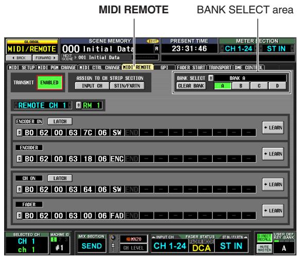
2 In the BANK SELECT area at the upper right of the screen, use the A-D buttons to select the bank you want to use.
3 In the upper middle of the screen, use the ASSIGN TO CH STRIP SECTION buttons to select the MIDI remote channel you want to control. (Multiple simultaneous selections are allowed.)

| INPUT CH | INPUT channel strip 1–24 |
| STIN/FXRTN | ST IN/FX RTN channel strip 1–4 |
This setting applies to all four banks.
Turning on a button will enable the MIDI Remote function; the corresponding channel strip will function as MIDI remote channels. (The usual function of the controllers will be disabled.)
At this time, the lower part of the display will indicate "REMOTE" in the encoder/fader mode area. The INPUT CH layer and ST IN/FX RTN layer indications will change to the corresponding MIDI remote channel.
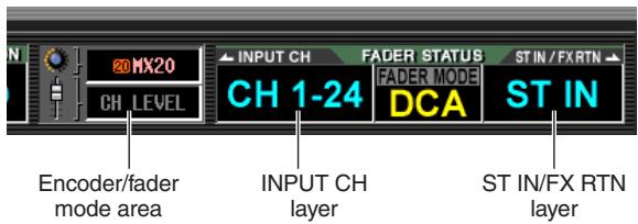
4 Operate the appropriate channel strip. MIDI messages will be transmitted from the corresponding MIDI port.
5 To disable the MIDI Remote function, turn off the ASSIGN TO CH STRIP SECTION buttons. Note
- When the MIDI Remote function is enabled, the controllers will return to their normal state if you switch to another screen. However when you come back to the MIDI REMOTE screen, the remote function of the controllers will be enabled.
- The controller values during MIDI Remote operation are included in the scene data. This means that when you recall a scene, the controller values will change and MIDI messages will be transmitted. Recall Safe settings can also be applied to the MIDI Remote function.
Transmitting MIDI events when you switch scenes
You can register a desired MIDI message for each scene in scene memory so that this message will be transmitted from the MIDI OUT connector when you recall the scene. For example you can use this to switch programs on an external MIDI-compatible effect processor when the scene changes.
1 Connect the MIDI OUT connector of the PM5D to the MIDI IN connector of the external device.
2 In the DISPLAY ACCESS section, press the [SCENE] key several times to access the SCENE screen shown below.
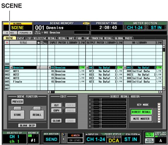
3 Scroll the scene list upward or downward to select the scene number for which you want to assign a MIDI event.
4 Scroll the scene list toward the right to display the MIDI EVENT column.
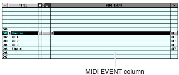
In the MIDI EVENT column you will input the MIDI message that will be transmitted when you recall that scene.
5 Click the button at the left edge of the MIDI EVENT column to open the MIDI EVENT SETUP window.
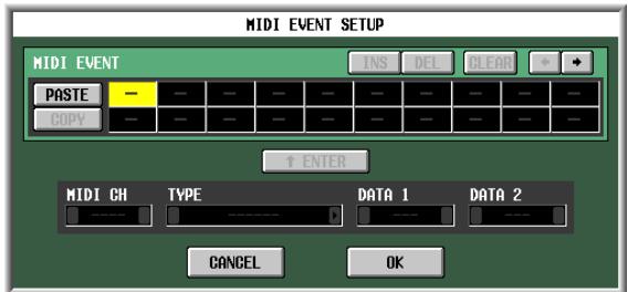
6 Use the MIDI EVENT SETUP window to specify the MIDI message that will be linked with that scene.
The procedure for specifying a MIDI message in the MIDI EVENT SETUP window is the same as in the MIDI REMOTE screen MIDI REMOTE SETUP window, with the exceptions that you cannot select FAD, ENC, or SW for the DATA 1/DATA 2 boxes, and that there is no LEARN button. (For details, refer to p.128) When you have finished making settings, click the OK button in the MIDI EVENT SETUP window.
7 Click the Tx ON/OFF column located at the right of the MIDI EVENT column to turn it on.
The MIDI event linked to the corresponding scene is now enabled.
Note
If necessary, you can adjust the timing at which the MIDI events linked to the scene are transmitted ( p.176) .
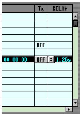
8 In the same way, specify MIDI events for other scene numbers.
9 Recall a scene to which a MIDI event is linked.
The MIDI message will be transmitted from the specified MIDI port.
The GPI connector on the rear panel can be used as a GPI (General Purpose Interface) input/output connector. This connector provides four GPI IN ports and twelve GPI OUT ports. For example you can use an external switch or joystick to control the PM5D's parameters, or conversely use the PM5D's keys and faders to send control signals to an external device.
The following diagram is an example of an external circuit that can operate GPI via the GPI connector. (For specifications of the GPI connector pins, refer to the Appendices p.388 and p.394 at the end of the manual.)
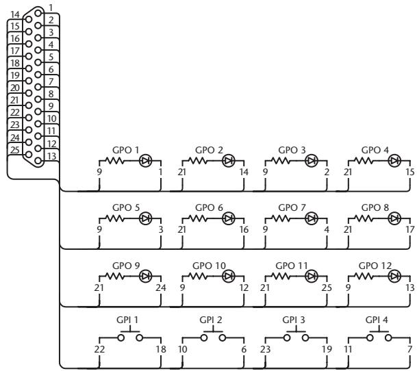
This circuit uses four switches (GPI 1-GPI 4) to switch the GPI IN ports between active and inactive. If the polarity of a GPI OUT port is set to Low Active, and you operate the PM5D to make the GPI OUT port Active, the corresponding LED in the above circuit (GPO 1-GPO 12) will light. (If the polarity of the GPI OUT port is High Active, the LED will go dark.)
Using GPI IN
You can use the GPI IN ports of the GPI connector to control PM5D parameters from an external device. For example you can use an external switch to turn the PM5D's talkback on/off or to operate its Tap Tempo function, or you can use a joystick to control surround panning.
1 Connect an external device to the PM5D's GPI connector.
2 In the DISPLAY ACCESS section, press the [MIDI/REMOTE] key several times to access the GPI screen shown below.
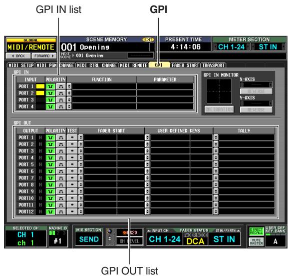
In this screen, the upper list is used to make GPI IN settings and the lower list is used to make GPI OUT settings.
3 In the POLARITY column of the GPI IN list, select the polarity of each GPI IN port.
You can select one of the following as the polarity for a GPI IN port.
Low active)
When controlling an on/off switch-type parameter, the port will become active when the switch is grounded. When controlling a continuously-variable parameter, that parameter will be at its maximum value when the voltage is at low level (by default, 0V), and at its minimum value when the voltage is at high level (by default, approximately 5V).
- n (High active)
When controlling an on/off switch-type parameter, the port will be active when the switch is opened or when a high-level voltage is input.
When controlling a continuously-variable parameter, that parameter will be at its minimum value when the voltage is at low level, and at its maximum value when the voltage is at high level.
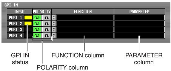
While the GPI screen is displayed, the GPI IN status column of the GPI IN area will show a yellow bar graph to indicate the approximate value of the voltage being input to each port. (If the bar is not shown, the voltage is grounded; if the bar is displayed all the way to the right edge, the voltage is at high level.)
Hint
The voltage value at which the PM5D detects High or Low level can be adjusted to suit the external controller (except for external switches) you are using ( p.135) .
4 At the left edge of the FUNCTION column, click the button to open the GPI IN PORT ASSIGN window.
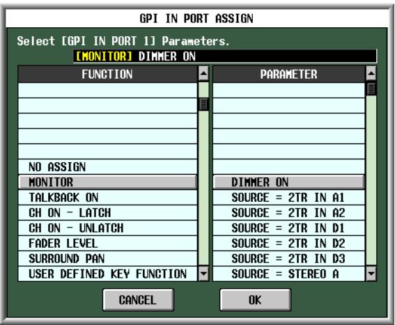
In the GPI IN PORT ASSIGN window you can select the PM5D function that will be controlled by each GPI IN port.
Use the FUNCTION column to select the type of function, and use the PARAMETER column to select the optional parameters. You can select the following functions and parameters.
| FUNCTION | PARAMETER | PM5D operation |
| NO ASSIGN | — | No assignment |
| MONITOR | DIMMER ON | Switches the Dimmer func-tion on/off |
| SOURCE = [monitor source name] | Switches the monitor source | |
| MONO ON | Switches the Monitor section [MONO] key on |
| FUNCTION | PARAMETER | PM5D operation |
| TALK-BACK ON | LATCH | Switches the Talkback func-tion on/off (latched operation) |
| UNLATCH | Switches the Talkback func-tion on/off (unlatched oper-ation) | |
| CH ON-LATCH | [channel name] | Switches the channel on/off (latched operation) |
| CH ON-UNLATCH | [channel name] | Switches the channel on/off (unlatched operation) |
| FADER LEVEL | [channel name] | Modifies the fader value (LEVEL parameter) accord-ing to the voltage |
| SUR-ROUND PAN | FRONT-REAR PAN [SEL] | Modifies the surround pan-ning (front/rear) of the selected channel according to the voltage |
| LEFT-RIGHT PAN [SEL] | Modifies the surround pan-ning (left/right) of the selected channel according to the volt-age | |
| FRONT-REAR PAN [ODD] | Modifies the surround pan-ning (front/rear) of the selected odd-numbered channel according to the volt-age | |
| LEFT-RIGHT PAN [ODD] | Modifies the surround pan-ning (left/right) of the selected odd-numbered channel according to the voltage | |
| FRONT-REAR PAN [EVEN] | Modifies the surround pan-ning (front/rear) of the selected even-numbered channel according to the volt-age | |
| LEFT-RIGHT PAN [EVEN] | Modifies the surround pan-ning (left/right) of the selected even-numbered channel according to the voltage | |
| USER DEFINED KEY FUNCTION | [User Defined key bank / key number] | While the external input is active, executes the same operation as when the selected User Defined key is pressed |
| USER DEFINED KEY LED | [User Defined key bank / key number] | While the external input is active, lights the LED of the selected User Defined key |
| PEAK HOLD ON | — | Switches the Peak Hold func-tion on/off |
| OSCILLA-TOR ON | Switches the Oscillator on/off | |
| SOLO ON | Switches the Solo function on/off |
After you have specified the function and parameter, click the OK button.
Note
- If latched operation is selected, the port will change between active/inactive each time a trigger is input from an external switch. In this case, we recommend that you use a non-locking type of external switch.
- If unlatched operation is selected, the port will be active only while the signal from the external switch stays at high level or low level. In this case, we recommend that you use either a non-locking or a locking type of external switch as appropriate for your situation.
5 Specify the function and parameter for other GPI IN ports in the same way.
With these settings when you operate an external device to make the GPI IN port active, the corresponding PM5D function will be executed. (If a continuously-variable parameter is assigned, the parameter value will vary according to the change in voltage.)
Hint
The settings in the GPI screen apply to all scenes. These settings can also be saved on a memory card as SETUP data.
Calibrating the GPI IN ports
If necessary, the voltage values at which the PM5D detects Low and High levels can be adjusted appropriately for the voltage of the signals being input from the GPI IN port.
You can use this to set the variable range of a PM5D parameter to match the range of voltage change produced by a continuously-variable controller (such as a joystick).
1 Connect an external device to the PM5D's GPI connector.
2 In the DISPLAY ACCESS section, press the [MIDI/REMOTE] key several times to access the GPI screen.
3 In the GPI IN MONITOR area at the upper right of the screen, select the GPI IN port that you want to calibrate.
If you are calibrating a two-dimensional controller such as a joystick, click the 4 / 5 buttons at the left and right of the X-AXIS and Y-AXIS fields to specify the two GPI IN ports.
If you are calibrating only one GPI IN port, set one of them to "----" (no assignment).
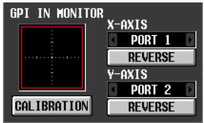
When you specify a GPI IN port, the voltage from that GPI IN port is indicated by a yellow symbol in the GPI IN monitor area. In this case, the horizontal position (X-axis) corresponds to the voltage of the GPI IN port selected in the X-AXIS field, and the vertical position (Y-axis) corresponds to the voltage of the GPI IN port selected in the Y-AXIS field.
The red line (or red square) displayed in the GPI IN monitor area indicates the range between High level and Low level for the GPI IN ports corresponding to the Y-axis and X-axis.
Hint
If necessary, you can click the REVERSE button to invert the Low level and High level of the input signal. (The result is the same as switching the POLARITY setting of the GPI IN port.)
4 Turn on the CALIBRATION button.
The red line (or red square) in the GPI IN monitor area will temporarily disappear, and only the yellow symbol will remain.
5 If you are calibrating only one GPI IN port, vary the voltage of the signal being input to the GPI IN port specified in step 3 from the maximum value to the minimum value.
The yellow symbol will move up/down or left/right as the voltage changes. The red line will extend according to this change, and the maximum and minimum voltage values for the corresponding GPI IN port will be stored.
6 If you are calibrating a joystick, move the joystick through a 360-degree path.
The yellow symbol will rotate. The red square will broaden accordingly, and the maximum and minimum voltage values of the GPI IN ports corresponding to the X-axis and Y-axis will be stored.
7 Turn off the CALIBRATION button.
The maximum and minimum voltage values detected will be remembered as the reference values for the High and Low levels. (When controlling a continuously variable parameter, the maximum value and minimum value of that parameter will be aligned with these reference values.)
Hint
The results of calibration apply to all scenes. They are also preserved even when the PM5D is powered-off.
Using GPI OUT
Here's how you can use the GPI OUT ports of the GPI connector to control an external device from the PM5D's faders or keys.
1 To the PM5D's GPI connector, connect the external device that you want to control from the PM5D.
2 In the DISPLAY ACCESS section, press the [MIDI/REMOTE] key several times to access the GPI screen.
3 In the POLARITY column of the GPI OUT area, select the polarity of the signal that is output from each GPI OUT port.
The POLARITY column of the GPI OUT area selects one of the following two settings as the polarity of the signal that is output when the GPI OUT port becomes active.
-
(Low active)
Grounded when the GPI OUT port is active. -
n (High active)
Open when the GPI OUT port is active.
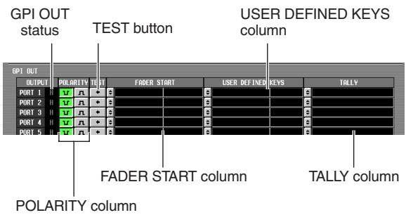
4 In the GPI OUT area, use the FADER START, USER DEFINED KEYS, and TALLY columns to select the PM5D function for GPI OUT ports 1 through 12.
When an operation selected here is executed on the PM5D, the corresponding GPI OUT port will become active, and a control signal will be output.
For each GPI OUT port you can select the following three functions (multiple selections are allowed).
□ FADER START
A fader operation on the PM5D will be the trigger for outputting a signal from the GPI OUT port.
To edit the setting, click the button at the left to open the GPI OUT PORT ASSIGN window, and select the fader mode (trigger detection method) and channel. You can select the following fader modes.
- FADER START
A control signal (trigger signal) 250 msec long will be output when the fader of the selected channel moves from -60 dB or below to above -60 dB.
- FADER STOP
A control signal (trigger signal) 250 msec long will be output when the fader of the selected channel reaches - dB.
- FADER TALLY
A control signal will be output when the fader of the selected channel moves from -60 dB or below to above -60 dB. This control signal will be held until the fader reaches - dB (or until that GPI OUT port receives a different trigger).
The following illustration shows how the output signal from the GPI OUT port changes when you operate a fader in each of the fader modes. (This illustration shows operation when u is selected as the POLARITY of the GPI OUT port. If POLARITY is n , the polarity of the output signal will be the opposite.)
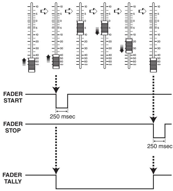
Note
When the voltage is at High level, the output signal of the port will be open. If the receiving device requires High level, it can be taken from the +5 power supply pin. However in this case there is a limitation on the current flow; for details, refer to the Appendices at the end of this manual.
USER DEFINED KEYS
Operation of a User Defined key on the PM5D will be the trigger for outputting a signal from the GPI OUT port.
To edit the setting, click the button at the left to open the GPI OUT PORT ASSIGN window; from the list, select the User Defined key bank (A-D) and number (1-25), and choose the trigger mode (how the trigger will operate when the key is pressed). You can choose one of the following trigger modes.
LATCH
Alternate between active and inactive each time the key is pressed.
- UNLATCH
Active only while the key remains pressed.
The following illustration shows how the output signal from the GPI OUT port changes when you operate a User Defined key in each of the trigger modes. (This illustration shows operation when u is selected as the POLARITY of the GPI OUT port. If POLARITY is n , the polarity of the output signal will be the opposite.)
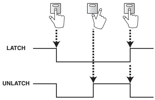
TALLY (other)
Other operations on the PM5D will be the trigger for outputting a signal from the GPI OUT port. When the corresponding operation is executed on the PM5D, a control signal will be output. This control signal will be held until you defeat the above operation (or until that GPI OUT port receives a different trigger).
To edit the settings, click the button at the left to open the GPI OUT PORT ASSIGN window, and select one of the following functions.
| Function | PM5D operation |
| NO ASSIGN | No assignment |
| POWER ON | The PM5D's power is turned on |
| SOLO ON | [SOLO] key is turned on |
| GPI IN 1 FUNCTION | The function assigned to GPI IN port 1 becomes active |
| GPI IN 2 FUNCTION | The function assigned to GPI IN port 2 becomes active |
| GPI IN 3 FUNCTION | The function assigned to GPI IN port 3 becomes active |
| GPI IN 4 FUNCTION | The function assigned to GPI IN port 4 becomes active |
| PREVIEW ON | SCENE MEMORY section [PREVIEW] key is turned on |
| CUE ON [INPUT ONLY] | Input channel [CUE] key is turned on |
| CUE ON [DCA ONLY] | DCA [CUE] key is turned on |
| CUE ON [OUTPUT ONLY] | Output channel [CUE] key is turned on |
| CUE ON | Any [CUE] key is turned on |

Make settings for other GPI OUT ports in the same way.
With these settings, executing an operation assigned to the GPI OUT port will output a control signal according to the POLARITY setting.
You can use the TEST buttons in the GPI OUT area to check the operation of the GPI OUT ports. When a TEST button is on, the corresponding GPI OUT port will become active, and a control signal will be output.
The GPI OUT status column indicates the status of the output signal of the corresponding port. The characters L/H indicate the Low or High level of the signal.
The background color is yellow when active, and gray when inactive.
17 Using memory cards
This chapter explains how to save/load PM5D/DSP5D internal data using a memory card.
Using memory cards with the PM5D
You can insert a commercially available memory card into the memory card slot located on the front panel of the PM5D, and use it to save or load various types of data.
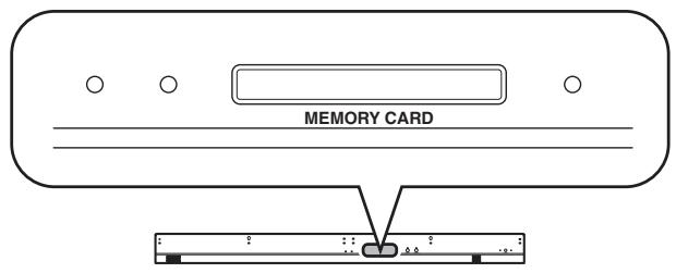
You can use PCMCIA Type II PC flash ATA cards, or CompactFlash media inserted in a PC card adaptor. (In either case, media with a power supply voltage of 3.3V or 5V is supported.) Normally, these cards are sold in an already-formatted state. This means that you won't need to format them before using them with the PM5D. If you do need to format a card, use a computer or other external device to format the card in FAT16 format.
Note
Operation is not guaranteed for any type of media other than described above.
Saving files to a memory card
Here's how to save individual items of data (or all data) from the PM5D/DSP5D onto a memory card. If the PM5D and DSP5D are cascade-connected, the settings of each machine can be consecutively saved by a single operation.
1 Insert the memory card into the memory card slot located on the front panel of the PM5D. You may insert or remove cards while the PM5D is powered-on.
2 In the DISPLAY ACCESS section, repeatedly press the [UTILITY] key to access the SAVE screen.
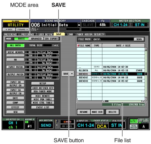
In the left side of the SAVE screen you can select the save mode and the item(s) that will be saved. The file list in the right side of the screen contains four columns; FILE NAME, TYPE, DATE/SIZE, and COMMENT. This list shows the files and directories on the memory card. (To see the COMMENT column, scroll the list toward the right.)
3 In the MODE area, click the BASIC button to select BASIC as the save mode.
If BASIC mode is selected, you can choose the desired item (or all items) and save them to a memory card.
Hint
The other save modes provided are ADVANCED mode which lets you save scene memories or libraries under different numbers, and CSV EXPORT mode which lets you save the names of scene memories or libraries as a CSV format file. For details, refer to the Reference section (p.212).
Note
If a DSP5D (machine #2 or #3) is selected, you can't save CSV format files. Please use DSP5D Editor.
4 Use the buttons below the MODE area to select the item you want to save.
The item whose button is turned on is selected for saving. (You can turn on only one button.) By clicking the ALL DATA button you can select all items at once. These buttons correspond to the following items.
| Button | Content |
| ALL DATA | All items, and the contents of the current scene |
| SCENE MEMORY | Contents of scene memory |
| LINKED LIBRARY | Libraries linked to the scene (available only if the SCENE MEMORY button is on) |
| HA | Contents of the HA library |
| INPUT PATCH | Contents of the input patch library |
| OUTPUT PATCH | Contents of the output patch library |
| INPUT CH | Contents of the input channel library |
| OUTPUT CH | Contents of the output channel library |
| INPUT EQ | Contents of the input EQ library |
| OUTPUT EQ | Contents of the output EQ library |
| GATE | Contents of the gate library |
| COMP | Contents of the compressor library |
| EFFECT | Contents of the effect library |
| GEQ | Contents of the GEQ library |
| SETUP | Various settings not saved in a scene |
| USER DEFINED KEY | User Defined key settings |
| DCA FADER MODE | DCA fader mode settings |
| MIDI REMOTE | MIDI remote settings |
| MIDI PGM TABLE | Contents of the list in the MIDI PGM CHANGE screen |
| MIDI CTRL TABLE | Contents of the list in the MIDI CTRL CHANGE screen |
| EVENT LIST | Contents of the list in the EVENT LIST screen |
If you select the SCENE MEMORY, HA, INPUT PATCH, or OUTPUT PATCH items, you can specify the starting number and ending number so that only the desired range of scenes or library items will be saved. The LINKED LIBRARY button is available only if the SCENE MEMORY button is on.
Hint
The TOTAL SIZE field at the bottom of the MODE area indicates the file size for the selected item(s). The available capacity of the inserted memory card is shown below the file list.
5 If you selected scenes or libraries for saving, use the boxes at the right of the button to specify the starting number and ending number.
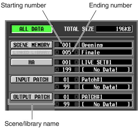
6 As necessary, use the file list to select the directory (folder) in which you will save the data.
If the file list contains a directory below the current level, the TYPE column will indicate "[DIR]."
| EVENTPA1 | ALL | 03/06/2004 04:01:06 | 196KB |
| EVENTPA2 | ALL | 03/06/2004 04:01:44 | 196KB |
| HALLSET1 | ALL | 03/06/2004 04:02:02 | 196KB |
| HALLSET2 | ALL | 03/06/2004 04:02:20 | 196KB |
| SETTING | [DIR] | 03/06/2004 04:03:10 | |
A directory below the current level
To move to a lower directory, click the directory line to select it (that line will move to the center of the list), and click the directory name shown in the FILE NAME column.
If the file list contains a directory above the current level, it will be shown as ". . ." in the FILE NAME column and "[DIR]" in the TYPE column.
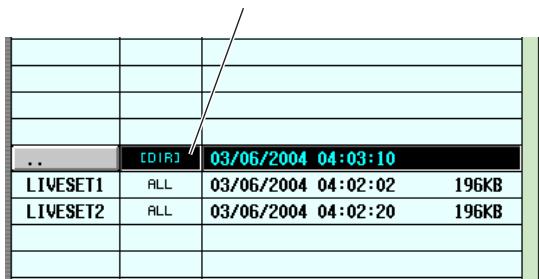
A directory above the current level
To move to a higher directory, click the directory line to select it (that line will move to the center of the list), and click the “.” shown in the FILE NAME column.
Hint
- The directory currently selected as the save destination is also shown in the FILE PATH field above the list
- If you want to create a new directory in the current location, click the MAKE DIR button below the file list.
Note
- The file list can display only up to one hundred items.
- Saving is not possible if the FILE PATH field exceeds 60 characters (including the filename extension).
7 After specifying the item to be saved and the save-destination directory, click the SAVE button.
The FILE SAVE window will appear, allowing you to assign a name to the data that will be saved.
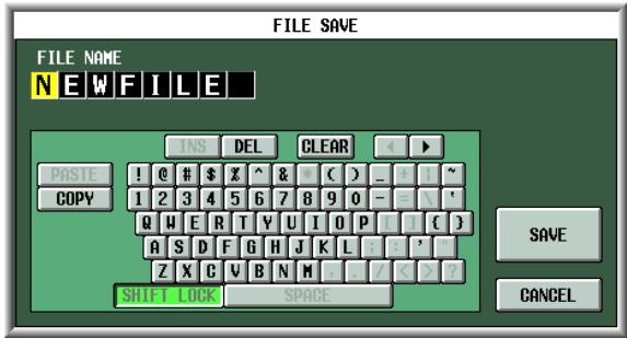
Use the character palette to input a filename, and click the OK button.
A window will ask you to confirm the Save operation.
Note
- When assigning a name to a file on a memory card, lower-case alphabetical characters and some symbols in the character palette cannot be used.
- If you paste text copied from another character palette when inputting the file name, all lowercase alphabetical characters will be converted to uppercase.
9 To execute the Save operation, click the OK button.
A window will appear, indicating the progress of the Save operation. If you click the CANCEL button instead of the OK button, the Save operation will be aborted.

Do not insert or remove the memory card while it is being accessed. A BUSY indicator at the upper right of the display will light while the card is being accessed.
10 If the PM5D and DSP5D are cascade-connected, a window will appear in which you can save the settings of the second and subsequent machines (DSP5D).
As necessary, repeat steps 7-9 to save the settings for each machine individually. If you don't need the settings for the second and subsequent machine, click the CANCEL button to abort the save operation. When the save operation is finished, you will return to the previous screen.
Hint
To avoid loading the data into the wrong machine, in the FILE SAVE window that appears, the machine ID number (2 or 3) will automatically be appended to the end of the file name for the second and subsequent units.
Loading files from a memory card
Here's how to load data from a memory card into the PM5D/PM5D.
1 Insert the memory card containing the data you want to load into the memory card slot located on the front panel of the PM5D.
2 If the PM5D and DSP5D are cascade-connected, switch to the machine into which you want to load the settings.
For details on how to switch the machine that is the target of panel control, refer to p.40.
3 In the DISPLAY ACCESS section, repeatedly press the [UTILITY] key to access the LOAD screen.
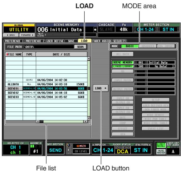
4 As necessary, use the file list to specify the load-source directory.
Navigation between directories is the same as in the file list of the SAVE screen (p.139). The currently selected directory is also shown in the FILE PATH field above the list.
5 In the file list, click the line showing the file you want to load.
That file will move to the center of the list, and will be highlighted.
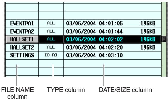
The file list shows the following information.
FILE NAME column
This column shows the names of the files saved on the memory card. If a directory is selected, the directory name is shown.
TYPE column
This column shows the content that was saved. The indication in the TYPE column will be one of the following.
| ALL | A file in which all items were saved |
| [DIR] | A directory |
| UNKNOWN | A file that cannot be loaded by the PM5D |
| Other | A file in which a specific item was saved |
Hint
For scene memory data, the type can be either "SCENE" in which only scene memory data is saved, and "SCENE+LIB" in which linked libraries are included.
DATE/SIZE column
This shows the date on which the file was last saved, and its size. If a directory is selected, only the date is shown.
COMMENT column
This shows the comment assigned when the file was saved. To input a comment, scroll the file list horizontally and click the COMMENT column for the currently selected file.
Hint
By clicking the headings at the top of the list, you can sort the list in ascending or descending order of that item. The text of the currently selected button will turn red, and an arrow indicating ascending () or descending () order will appear.
6 In the MODE area, click the BASIC button to select BASIC as the loading mode.
Similarly to the Save mode in the SAVE screen, you can choose either BASIC, ADVANCED, or CSV IMPORT as the Load mode. If BASIC mode is selected, the item buttons appropriate for the currently selected file will turn on.
Hint
- If ADVANCED mode is selected, you can specify the range of scenes or library numbers that will be loaded from a scene memory and/or library file saved in BASIC mode or ADVANCED mode.
- If CSV IMPORT is selected, you can load CSV files that were saved in CSV EXPORT mode. For details on each mode, refer to the Reference section (→ p.212).
Note
- If you select a directory in the file list, the Load mode will automatically switch to CSV IMPORT, and the screen will indicate whether that directory contains any CSV files. If you subsequently select any file readable by the PM5D other than a CSV file, the mode will automatically switch to BASIC.
- If the type of file to be loaded is ALL DATA, the entire contents of the PM5D/DSP5D's scene memories and libraries will be rewritten. Before loading, make sure you are not accidentally overwriting important scenes or library data.
- If a DSP5D (machine #2 or #3) is selected as the target of control, CSV files can't be loaded. If you need to load a CSV file, please use DSP5D Editor.
7 When loading scenes or libraries, you can click the / buttons at the left and right of the boxes beside each button to select the scene or library numbers that will be loaded.
8 Click the LOAD button.
A window will ask you to confirm the Load operation.
9 To execute the Load operation, click the OK button.
Note
Loading cannot be executed if cascade connection is enabled.
A window will appear, indicating the progress of the Load operation. When loading is completed, the previous screen will reappear.
If you click the CANCEL button instead of the OK button, the Load operation will be aborted and you will return to the previous screen.
!
Do not insert or remove the memory card while it is being accessed. A BUSY indicator at the upper right of the display will light while the card is being accessed.
Note
- If the LOAD LOCK button is on, synchronization can occur only from this unit to PM5D Editor/DSP5D Editor (not the reverse) when synchronizing with PM5D Editor/DSP5D Editor.
- Be aware that scene memories for which "R" (read only) is indicated in the SCENE function SCENE screen will not be loaded, but the linked libraries will be loaded.
18 Surround pan
This chapter explains how to use the surround pan functionality.
About surround pan
"Surround pan" is functionality that, when used with a multi-channel playback system, lets you place the signal of an input channel in two-dimensional space or move the sound image between front/back and left/right. (To move the surround pan image, you can use the mouse, the CURSOR [] / [] / [] / [] keys, or the MIX encoders etc.)
The PM5D lets you choose from the following three surround modes, depending on the number of channels in your surround environment.
3-1ch
This mode uses four channels; left and right front, front center, and rear (surround).
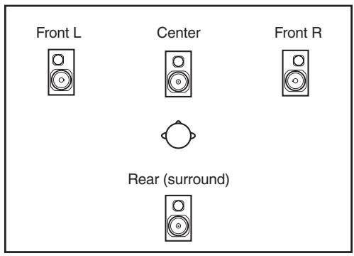
5.1ch
This mode uses six channels; left and right front, left and right rear, front center, and subwoofer.
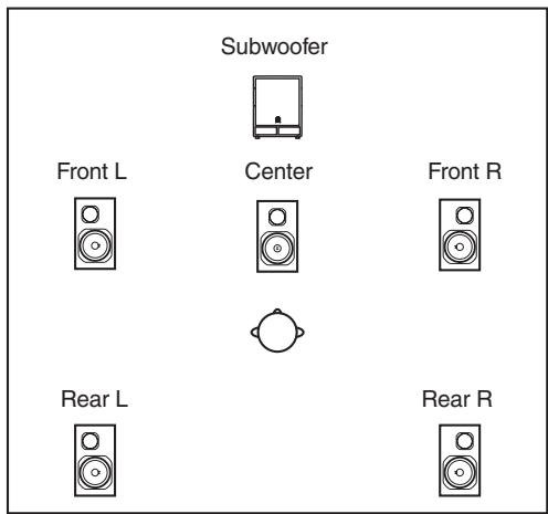
6.1ch
This mode uses seven channels; 5.1ch with the addition of rear center.
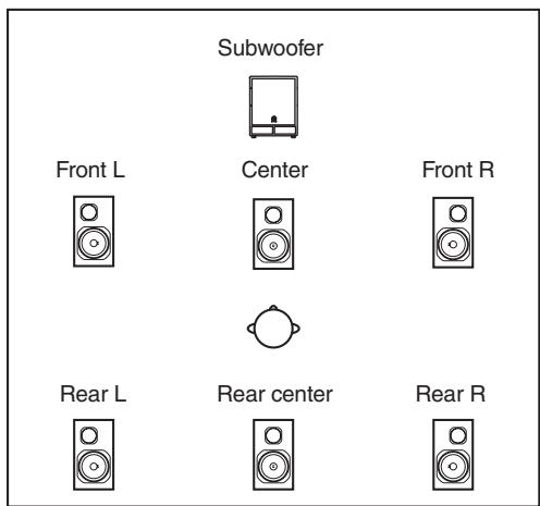
Hint
The surround mode can be selected in the MIXER SETUP screen (SYS/W.CLOCK function) or SURR SETUP screen (MATRIX/ST function).
When any of the three surround modes (3-1ch, 5.1ch, 6.1ch) are selected, the PM5D's bus configuration and operation will change as follows.
About the surround buses
While a surround mode is selected, MIX buses 1-8 or MIX buses 9-16 can be used as surround buses. (The choice of whether to use MIX buses 1-8 or MIX buses 9-16 is made in the MATRIX/ST function SURR SETUP screen.)
When you switch the surround mode, the following surround channels will be assigned by default to each of the MIX buses. (You are free to change these assignments subsequently.)
| Surround mode MIX bus | 3-1ch | 5.1ch | 6.1ch |
| MIX bus 1/9 | L (Front L) | ||
| MIX bus 2/10 | R (Front R) | ||
| MIX bus 3/11 | C (Center) | Ls (Rear L) | |
| MIX bus 4/12 | S (Surround) | Rs (Rear R) | |
| MIX bus 5/13 | C (Center) | ||
| MIX bus 6/14 | LFE (Subwoofer) | Bs (Rear center) | |
| MIX bus 7/15 | LFE (Subwoofer) | ||
| MIX bus 8/16 | |||
Note
MIX buses shaded in gray in this table can be used as conventional MIX buses. However in 6.1ch mode, the MIX 8/16 bus will operate only as FIXED type.
For example when the surround mode is 6.1ch and you have chosen MIX 1-8 to use as the surround buses, the surround pan signal flow will be as follows.
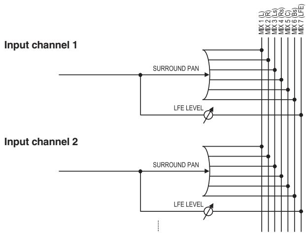
How the MIX section will operate
When a surround mode is selected, the MIX encoders allocated to surround buses will operate differently than normal. For example if MIX buses 1-8 are being used as surround buses, you can use MIX encoders 1-8 of the MIX section to edit the following parameters.
If the MIX section [MIX SEND] key is on
![YAMAHA PM5D-RH - If the MIX section [MIX SEND] key is on - 1](/content/2025/01/115055/images/97d68924b30a81de963ef35e7689f3a1a9b179d657d2a452588e28b0f7e9bf8c.jpg)
① L R
Moves the surround pan of the selected channel between left and right.
② F R
Moves the surround pan of the selected channel between front and rear.
(3) Front divergence (5.1ch and 6.1ch modes only)
Adjusts the front divergence (the proportion at which a signal panned to the center will be sent to the front center bus and to the front LR buses) of the selected channel. Front divergence (the DIV F parameter) can be adjusted if 6.1ch mode is being used.
④ Rear divergence (6.1ch mode only)
Adjusts the rear divergence (the proportion at which a signal panned to the rear will be sent to the rear center bus and to the rear LR buses) of the selected channel.
(5) LFE (5.1ch and 6.1ch modes only)
Adjusts the send level of the signal sent from the selected channel to the LFE (Low Frequency Effects) bus.
Hint
- For details on each of the surround pan parameters, refer to SURR PARAM screen (▶ p.309) in the Reference section.
- If MIX buses 9-16 are being used as surround buses, you can use MIX encoders 9-16 to perform the above operations.
If the MIX section [MIX MASTER] key is on
![YAMAHA PM5D-RH - If the MIX section [MIX MASTER] key is on - 1](/content/2025/01/115055/images/75eda805c0585be86ccdf357e5ee42e39fc4cdfc628826a6e81b6d1ad1e6853e.jpg)
Basic settings for surround buses
Here's how to choose either 3-1ch, 5.1ch, or 6.1ch as the surround mode, and make settings for the MIX buses you will use as surround buses.
1 According to the surround mode you intend to use, connect an appropriate playback system to MIX OUT jacks 1-8 or MIX OUT jacks 9-16.
2 In the DISPLAY ACCESS section, repeatedly press the [MATRIX/ST] key to access the SURR SETUP screen.
In order to use a surround mode, you will first choose a surround mode, and then specify the MIX buses that will be the surround output destinations.
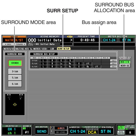
3 Click a button in the SURROUND MODE area to select the desired surround mode.
When you click a button a window will appear, asking you to confirm that you want to switch the surround mode.
① Output level
The encoders adjust the output level of each surround channel.
Click the OK button to enable the surround mode you selected. For example if you switch to 6.1ch mode, the screen display will change as follows.
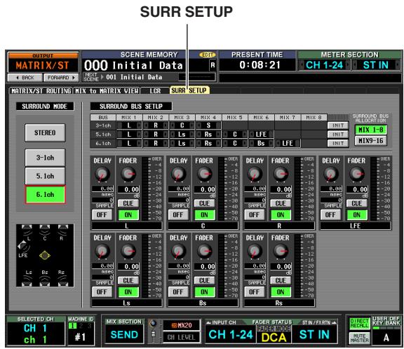
4 In the SURROUND BUS ALLOCATION area, press the MIX 1-8 button or the MIX 9-16 button to select the MIX buses you want to use as surround buses.
You can select either MIX buses 1-8 or MIX buses 9-16. When you click a button a window will appear, asking you to confirm that you want to change the MIX bus allocation.
When you click the OK button, the selected MIX buses will be allocated as surround buses, and will be assigned to surround channels according to the current surround mode.
5 If you want to change the surround channel assignments, click the l buttons at the left and right of each field in the bus assign area, and press the [ENTER] key (or click within the box) to confirm the setting.
When the setting is confirmed, the previously-selected bus and the newly-assigned bus will be exchanged.
Hint
You can initialize the surround channel assignments by clicking the INIT button located at the right of the bus assign area.
6 Use the knobs and buttons in the lower part of the screen to adjust the volume, delay, on/off status, and cue for each surround channel.
For details on these knobs and buttons, refer to SURR PARAM screen ( p.309) in the Reference section.
7 In the MIX section, make the [MIX MASTER] key light, and turn on the MIX [ON] keys of all MIX buses that will be used as surround buses.
The signal of each surround bus is now sent from the corresponding MIX OUT jack.
Controlling surround pan
Here's how to control surround pan for two adjacent input channels (or ST IN/FX RTN channels L and R).
Note
- Before you continue with the following procedure, you must select the desired surround mode and connect MIX OUT jacks 1–8 or MIX OUT jacks 9–16 to an appropriate playback system, as described in "Basic settings for surround buses" (→ p.144).
- If you use 5.1ch or 6.1ch surround mode, connect the LFE (Low Frequency Effects) channel signal to a dedicated subwoofer for the low frequencies. However, simply switching the surround mode does not change the EQ (filter) settings. As necessary, use the EQ (LPF) of the MIX channel assigned to the LFE channel to cut the high-frequency portion of the signal according to the frequency response of the subwoofer you are using.
1 In the DISPLAY ACCESS section, repeatedly press the [PAN/ROUTING] key to access the SURR PARAM screen (PAN/ROUTING function).
The SURR PARAM screen always shows surround pan settings for two channels.
![YAMAHA PM5D-RH - In the DISPLAY ACCESS section, repeatedly press the [PAN/ROUTING] key to access the SURR PARAM screen (PAN/ROUTING function). - 1](/content/2025/01/115055/images/51fd48e3d3064df1232559b02e925ad3d39b4395753306ffc80b4c1cfb1dadb1.jpg)
Surround pan grid
2 Use the channel selection area to select the input channels whose surround pan settings you want to edit.
Two adjacent odd-numbered/even-numbered channels (or ST IN/FX RTN channels L and R) will be displayed.
3 Use the SURROUND BUS ON/OFF buttons located around the surround pan grid to select the surround buses to which the input channel will be sent.
The SURROUND BUS ON/OFF buttons are on/off switches for the signal sent from the input channel to each surround bus.
Hint
You can do the same thing by pressing a [SEL] key to select an input channel, making the MIX section [MIX SEND] key light, and then turning on the MIX [ON] key for the desired surround buses.
4 Use any of the following methods to adjust the surround pan of the selected channel.
- Using the mouse or track pad
Move the pointer into the surround pan grid of the channel you want to control, and drag the yellow O symbol forward/backward/left/right. (The symbol will turn red while you are dragging it.) Alternatively, you can click a desired location within the surround pan grid to move the surround pan to that location.
- Using the pan buttons around the surround pan area
If you want to quickly move the channel signal to the location of a speaker, click one of the pan buttons (e.g., L, R, C) shown around the edge of the surround pan grid.
- Using the CURSOR [] / [] / [] / [] keys
Move the cursor to the surround pan grid and press the [ENTER] key; the O symbol will turn red.
In this condition, you can use the CURSOR [] / [] keys to move surround pan left/right, or the CURSOR [] / [] keys to move it forward/backward, in a range of eight steps. By performing this operation while holding down the [SHIFT] key, you can quickly move surround pan in a range of 32 steps. To finalize the surround pan adjustment, press the [ENTER] key once again.
- Using the MIX encoders
If you turn on the [MIX SEND] key of the MIX section, you can use MIX encoders 1 or 9 to adjust the left/right position of the input channel, and MIX encoders 2 or 10 to adjust the front/rear position. The SARR PARAM screen MIX SECTION ASSIGNMENT area shows the parameters assigned to each MIX encoder.
- Using MIDI control changes or GPI
If you assign surround pan parameters to MIDI control changes or GPI, you can use an external device to control surround pan. For details, refer to MIDI CTRL CHANGE screen ( p.191) and GPI screen ( p.194) in the Reference section.
5 If you want surround pan operations to be linked for two adjacent channels, turn on the STEREO LINK button, and use the box at right to select the link pattern.
When you turn on the STEREO LINK button, surround pan will be linked for the two channels shown in the SARR PARAM screen. To specify how they will be linked, select one of the following link patterns by clicking the / buttons at the left and right of the box located to the right of the STEREO LINK button.
| Pattern 1 | →1 | The channels will move in the same direction for both the front/rear axis and the left/right axis. |
| Pattern 2 | →2 | The channels will move in opposite directions for the front/rear axis, and in the same direction for the left/right axis. |
| Pattern 3 | →3 | The channels will move in the same direction for the front/rear axis, and in opposite directions for the left/right axis. |
| Pattern 4 | →4 | Left↔right movement of the odd-numbered channel will be linked with rear↔front movement of the even-numbered channel. Front↔rear movement of the odd-numbered channel will be linked with left↔right movement of the even-numbered channel. |
| Pattern 5 | →5 | Left↔right movement of the odd-numbered channel will be linked with front↔rear movement of the even-numbered channel. Front↔rear movement of the odd-numbered channel will be linked with left↔right movement of the even-numbered channel. |
| Pattern 6 | →6 | Front/rear and left/right movement will both be linked in the opposite direction. |
| Pattern 7 | →7 | Left↔right movement of the odd-numbered channel will be linked with front↔rear movement of the even-numbered channel. Front↔rear movement of the odd-numbered channel will be linked with right↔left movement of the even-numbered channel. |
| Pattern 8 | →8 | Left↔right movement of the odd-numbered channel will be linked with rear↔front movement of the even-numbered channel. Front↔rear movement of the odd-numbered channel will be linked with left↔right movement of the even-numbered channel. |
6 Edit other parameters as desired.
In the SURR PARAM screen you can also edit the following parameters.
Divergence
These controls specify the proportion at which the signals are sent to each surround bus when the input channel is positioned in the center. The parameters that are displayed will depend on the surround mode that is currently selected. (For details, refer to p.309)
LFE
This adjusts the output level of the signal sent from the input channel to the LFE (Low Frequency Effect) bus for a subwoofer. You can also use the ON/OFF button to switch the signal sent from the input channel to the LFE bus on/off.
Hint
- The master level of each surround bus is shown in the upper right of the screen.
- You can use the SURR VIEW screen to see the surround pan settings of all channels at a glance.
Here are some notes and limitations that you should be aware of when using surround pan.
Scene recall operations
- The surround mode selection and the surround pan settings of each channel are stored as part of the scene.
- If you recall a scene whose surround mode differs from the current scene, the screen and panel display will change accordingly. The surround mode is recalled regardless of Selective Recall or Recall Safe settings.
- If one channel (of a pair of channels) is excluded from recall, and you recall a scene in which the STEREO LINK button is on, the STEREO LINK button will remain on but only the other channel (of the pair) will be recalled.
- SURROUND BUS SETUP settings (MIX bus 1-8/9-16 selection, and assignments to each surround channel) are not included in the scene data.
□ Channel library recall operations
- Surround pan related parameters for inputs are stored in the input channel library.
- If the STEREO LINK button is on, and you recall input channel library settings, the STEREO LINK button will remain on, but only one channel will be recalled. Subsequent operation will be according to STEREO LINK.
□ Channel copy
- When you copy an input channel using panel operations, surround-related parameters will also be copied.
- In order to copy surround-related parameters using the CH JOB screen (INPUT VIEW function), the ALL button must be turned on in the DESTINATION area.
Global paste
- In order to paste surround-related parameters, the ALL button must be turned on in the CURRENT SCENE area of the GLOBAL PASTE screen (SCENE function). In addition, the settings of the STEREO LINK area will also be pasted if two adjacent channels are selected.
19 Other functions
This chapter explains other functionality of the PM5D not covered elsewhere.
Using the user defined keys
You can assign the desired functions to the User Defined keys in the USER DEFINED section of the top panel, and press these keys to execute the defined function.
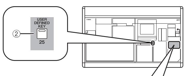
Items in the USER DEFINED section
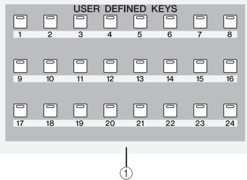
① USER DEFINED [1]–[24] keys
② USER DEFINED [25] key
These are User Defined keys that execute the assigned function.
Assigning functions to the User Defined keys
Here's how to assign the functions that will be executed when the USER DEFINED [1]–[25] keys are pressed.
1 In the DISPLAY ACCESS section, press the [UTILITY] key repeatedly to access the USER DEFINE screen shown below.
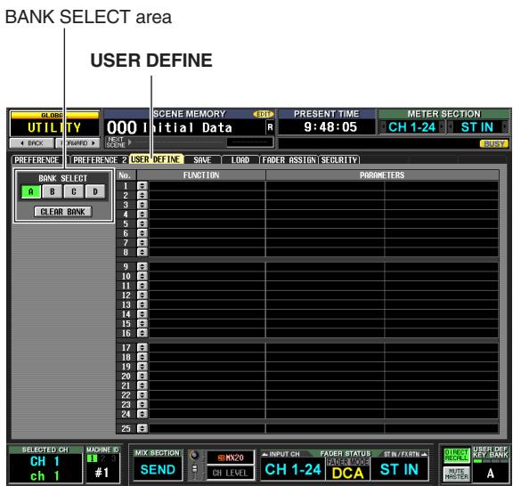
In this screen you can make User Defined key assignments for each of four banks; A-D.
2 In the BANK SELECT area at the upper left of the screen, use the A-D buttons to select the bank you want to use.
To clear the assignments of the current bank, click the CLEAR BANK button located at the bottom of the BANK SELECT area.
3 Click the button located on the line of the User Defined key you want to assign.
The USER DEFINED KEY ASSIGN window will appear. In this window you can select a function to assign to the User Defined key, and select option parameters.
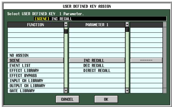
4 Select the desired function in the FUNCTION column, select parameters in the PARAMETER 1/2 columns, and click the OK button.
For details on the available functions and parameters, refer to the Reference section (p.208).
5 Assign functions to other keys and banks in the same way.
Hint
The User Defined key assignments are not saved in the scene. If desired, you can save the assignments on a memory card as USER DEFINED KEY data.
Executing functions assigned to the User Defined keys
Here's how to use the USER DEFINED [1]–[25] keys to execute the functions that have been assigned to them.
1 In the DISPLAY ACCESS section, repeatedly press the [UTILITY] key to access the USER DEFINE screen.
2 In the BANK SELECT area at the upper left of the screen, use the A-D buttons to select the bank (A-D) you want to use.
3 Press a USER DEFINED [1]–[25] key. The function assigned to that key will be executed.
Using the FADER MODE section
In the FADER MODE section you can switch the channels that are assigned to DCA faders 1-8 of the panel DCA strip. For each of six layers A-F, you can specify the channel that is assigned to each fader. For example, you might use this to simultaneously control the send level and return level of an internal effect, or to use a fader as the master fader of a MIX bus or MATRIX bus.
In tandem with switching the FADER MODE section layer, you can also switch the machine being controlled by panel operations, the INPUT channel strip, the ST IN/FX RTN channel strip, and the STEREO A/B channel strip layer.
For each layer you can specify the channel/machine/layer that is assigned to each fader, and use the FADER MODE section to switch between layers while you operate the faders.
Items in the FADER MODE section
In the FADER MODE section you can select the layers or DCA groups that will be controlled.
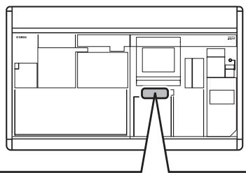
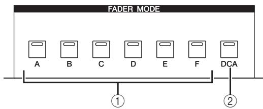
① FADER MODE [A]–[F] keys
These switch the layer for DCA faders 1-8, the machine affected by panel operations, the INPUT channel strip, the ST IN/FX RTN channel strip, and STEREO A/B channel strip.
② FADER MODE [DCA] key
If this button is on, DCA faders 1-8 will control DCA groups 1-8.
Assigning the FADER MODE section layer
Here's how to assign the desired channel/machine/layer to the FADER MODE section layers.
1 In the DISPLAY ACCESS section, repeatedly press the [UTILITY] key to access the FADER ASSIGN screen.
In this screen, you can select the desired channel/ machine/layer for each layer A-F.
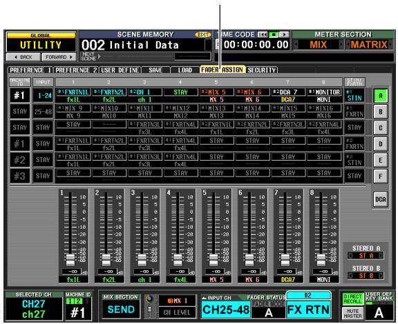
FADER ASSIGN
2 Use the channel selection boxes for the desired layer (A-F) to select the channel assigned to each fader 1-8.
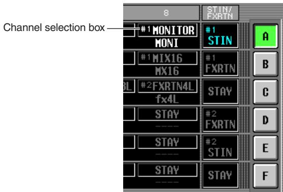
To select a channel, move the cursor to the box and turn the dial. The channel will blink; press the [ENTER] key to confirm. You can choose from the following channels.
| Item | Selected channel |
| CH 1-CH 48 | Input channel 1-48 |
| STIN1L/STIN1R-STIN4L/STIN4R | ST IN channel 1-4 L or R |
| FXRTN1L/FXRTN1R-FXRTN4L/FXRTN4R | FX RTN channel 1-4 L or R |
| MIX 1-MIX 24 | MIX channel 1-24 |
| MTRX1-MTRX8 | MATRIX channel 1-8 |
| DCA1-8 | DCA fader 1-8 |
| MONITOR | Output level from the MONITOR OUT L/R/C jacks |
| CUE | Output level from the CUE OUT jacks |
| ---- | Fader disabled |
| STAY | No change |
Hint
- If an input channel or a DCA fader 1–8 is selected, the channel name is displayed immediately below the channel selection box.
- Input channels and output channels can coexist in the same layer.
- Channels of each machine cascade-connected with the DSP5D are assigned to the channels that show the corresponding machine ID (#1--#3). Channels of the currently selected machine are assigned to the channels for which a machine ID is not shown. However, MONITOR and CUE are fixed at PM5D (#1).
3 As desired, use the MACHINE ID box corresponding to the layer (A-F) you want to operate to select the machine that will be controlled from the panel.
To select a machine, move the cursor and turn the [DATA] encoder and press the [ENTER] key to confirm. The machines that can be selected are "#1" (PM5D), "#2" (DSP5D), "#3" (DSP5D), or "STAY" (no change).

As desired, use the INPUT box and ST IN/FX RTN box for the layer (A-F) you want to operate to select the INPUT channel strip and ST IN/FX RTN channel strip layers.
To select a layer, move the cursor and turn the [DATA] encoder and press the [ENTER] key to confirm.
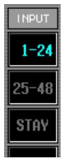
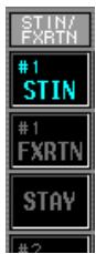
5 As desired, change the assignment of the STEREO A/B channel strip (fader and [ON] key).
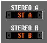
To change the assignment, move the cursor and turn the [DATA] encoder and press the [ENTER] key to confirm. You can select the following assignments.
STA/B STEREO A/B channels
- MONITOR
Output level from the MONITOR OUT L/R/C jacks
- CUE
Output level from the MONITOR OUT L/R/C jacks
6 In the same way, assign the channel/machine/ layer for other layers.
Hint
The settings of the FADER MODE section are not saved in the scene. If desired, you can save these settings on a memory card as DCA FADER MODE data.
Switching the FADER MODE section layer
1 In the FADER MODE section, use the FADER MODE [A]-[F] keys to select the layer you want to use.
The key LED will light, and the corresponding layer will become active. If input channels are assigned to the DCA faders, the channel names will appear in the name indicators of the DCA strip.
Hint
You can also switch layers from within the FADER ASSIGN screen. This screen also shows the values of the DCA faders and their approximate positions.
2 Operate the faders of the DCA strip.
The level of the corresponding channels will change. If a channel assigned to a DCA fader is paired (or if one side of a stereo channel is assigned), the level of the other paired channel (or the other side of the stereo channel) will follow.
Note
If a FADER MODE [A]-[F] key is on, the DCA channel strip [MUTE] keys can be used as [ON] keys of the corresponding channels. The [CUE] keys can also be used as [CUE] keys for the corresponding channels.
The PM5D lets you prohibit changes to certain parameters (Parameter Lock), disabling file loading (Load Lock), or prohibit operation of the console (Console Lock). For example, this lets you prevent an unauthorized person from operating the console while the engineer is taking a break.
You can also apply password protection to the lock function using a "system password" which is remembered even after power-off, or a "console password" which is cleared when the power is turned off. You will be able to use Parameter Lock, Load Lock, and Console Lock if you've specified a system password; you will only be able to use Console Lock if you've specified a console password.
Setting the System Password or Console Password
Here's how to set the password used for Parameter Lock and Console Lock. However, it is possible to apply the lock function even if a password has not been specified.
1 In the DISPLAY ACCESS section, repeatedly press the [UTILITY] key to access the SECURITY screen.
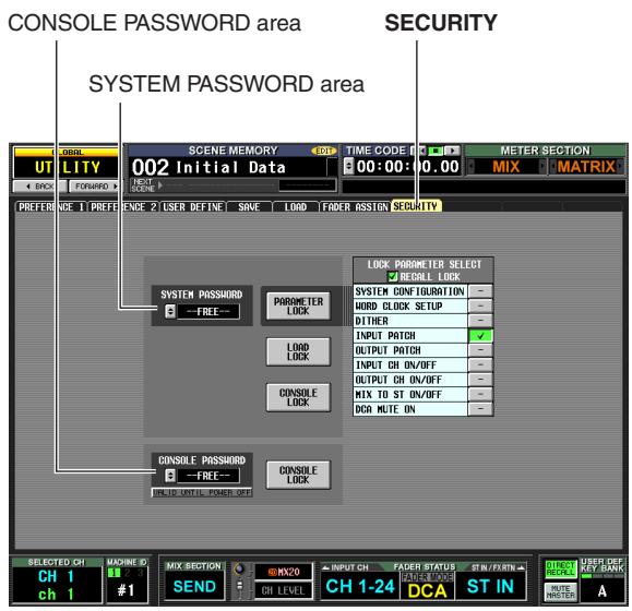
In this screen you can use the SYSTEM PASSWORD and CONSOLE PASSWORD fields located at the left to specify the passwords. (If no password has been specified, the corresponding box will indicate "--FREE--".)
2 To set the system password, click the button for the SYSTEM PASSWORD field. To set the console password, click the button for the CONSOLE PASSWORD field.
A window will appear, and you will be asked to input the new password. (The upper left of the window indicates "NEW PASSWORD.")
As an example, the illustration below shows the SYSTEM PASSWORD CHANGE window where you specify the system password.
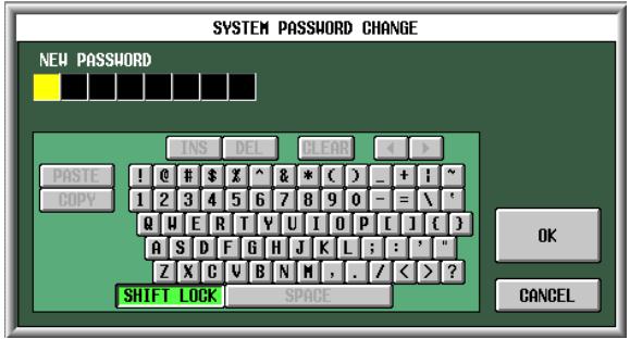
Note
- If a password has already been input, you will be requested to input the old password. (The upper left of the window indicates "OLD PASSWORD".) In this case, input the existing password and click the OK button before you continue to step 3.
- If you want to return the system to a condition in which a password has not been specified, input the existing password, click the OK button, and then leave the new password field blank when you execute steps 3-5.
3 Use the character palette to input a password of up to eight characters in the NEW PASS-WORD text box.
The characters you input are displayed as * asterisks).
Any character of the character palette except for SPACE can be used in a password. (The password is case-sensitive; i.e., uppercase and lowercase alphabetical characters are distinguished.) When inputting a password, the COPY, PASTE, SPACE, INS, , and keys of the character palette cannot be used.
4 Click the OK button.
The indication in the upper left of the window will change to "RE-ENTER PASSWORD".
5 Input the same password once again, and click the OK button.
The password will be applied, and you will return to the SECURITY screen.
Note
The console password will be cleared when the PM5D is powered-off. In contrast, the system password is remembered even after the power is turned off. This means that if you forget the system password, you will be unable to defeat Parameter Lock or Console Lock except by initializing the entire memory of the PM5D (p.160). Please be careful not to lose the system password.
Using Parameter Lock or Console Lock
Here's how to lock parameters or the console. You can also lock using the password you specified.
1 In the DISPLAY ACCESS section, repeatedly press the [UTILITY] key to access the SECURITY screen.
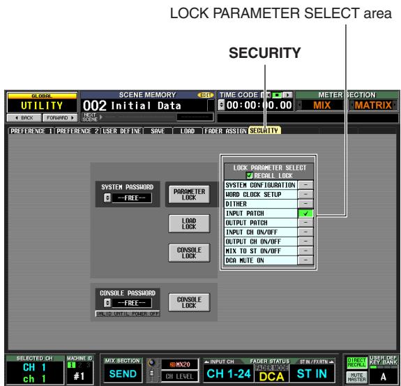
2 If you want to lock only specific parameters, use the buttons of the LOCK PARAMETER SELECT area to select the parameters for which you want to prohibit editing.
When you click a button, a check mark will appear for the selected item. You can select the following
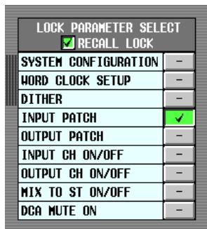
items (multiple selections are allowed).
| Item | Content |
| SYSTEM CONFIG-URATION | Changes to the settings of the MIXER SETUP screen and CASCADE screen |
| WORD CLOCK SETUP | Changes to the word clock setting |
| DITHER | Changes to dither-related settings |
| INPUT PATCH | Changes to the input patch settings (and names) |
| OUTPUT PATCH | Changes to the output patch settings |
| INPUT CH ON/OFF | Input channel on/off operations |
| OUTPUT CH ON/OFF | Output channel on/off operations |
| MIX TO ST ON/OFF | MIX TO STEREO button on/off operations |
| DCA MUTE ON | DCA [MUTE] key On operations (Off operations are not included) |
Note
- As long as the PARAMETER LOCK button is on, the above settings cannot be edited. You will need to defeat the lock function before editing them.
- If you turn on the RECALL LOCK button, the specified parameters will also be unaffected by scene or library recall operations.
3 Depending on the items you want to lock, click either the PARAMETER LOCK button, LOAD LOCK button or CONSOLE LOCK button.
If a password has been specified, a window will ask you to input the password. If you click the CANCEL button without inputting a password in this window, you will return to the previous screen.
Note
If the LOAD LOCK button is on, synchronization can occur only from this unit to PM5D Editor/DSP5D Editor (not the reverse) when synchronizing with PM5D Editor/DSP5D Editor.

4 Input the password you assigned beforehand, and click the OK button.
If you clicked the PARAMETER LOCK button in step 3, a message of "Parameter Locked" will appear briefly, and then editing will be disabled for the selected parameters.
If you clicked the CONSOLE LOCK button in step 3, an indication of "CONSOLE LOCKED" will appear on the screen, and all operations other than pressing the UNLOCK button will be disabled.
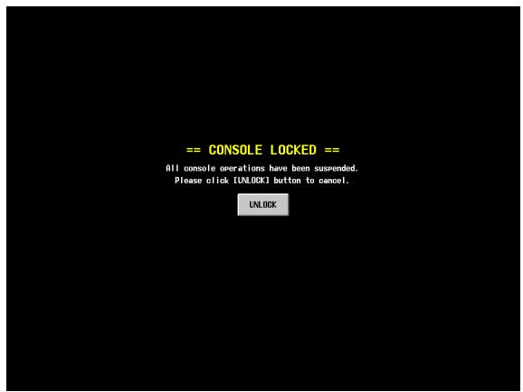
5 To defeat Parameter Lock, click the PARAMETER LOCK button. To defeat Console Lock, click the UNLOCK button.
If a password has been specified, a window will ask you to input the password. Input the password and click the OK button to defeat the lock function. You will return to the screen in which you were prior to applying the security setting.
Note
The console password will be cleared when the PM5D is powered-off. In contrast, the system password is remembered even after the power is turned off. This means that if you forget the system password, you will be unable to defeat Parameter Lock or Console Lock except by initializing the entire memory of the PM5D (p.160). Please be careful not to lose the system password.
You can share buses by cascade-connecting a PM5D and DSP5D, multiple PM5D units (maximum of four units), or a PM5D with an external mixer (Yamaha DM2000/02R96, etc.). When multiple PM5D/DSP5D units are cascade-connected, operations such as scene store/recall, cue/solo, and dimmer can also be linked.
Example of cascade connections between the PM5D and DSP5D
Up to two DSP5D units can be cascade-connected to one PM5D unit. By going through a DCU5D digital cabling unit, you can also utilize long-distance routing via Ethernet cable. For details, refer to p.31.
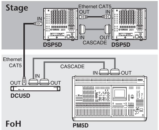
Example of cascade connections between PM5D units
Here we will explain cascade connections and operation, using an example in which two PM5D units are cascade-connected.
To cascade-connect two PM5D units, connect the CASCADE IN connectors and CASCADE OUT connectors of the two units to each other. This allows the MIX bus, STE-REO bus, and CUE bus output signals to be transmitted and received between the two units.
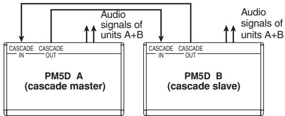
If you want operations such as scene store/recall and cue/ solo to be linked between the two PM5D units, specify one unit as the cascade master and the other as the cascade slave. (This setting is made in the SYS/W.CLOCK function MIXER SETUP screen.) The PM5D assigned as the cascade master will output control signals (operational signals) via its CASCADE IN connector, and the PM5D assigned as the cascade slave will receive these signals via its CASCADE OUT connector.
Hint
- If you want to daisy-chain two to four PM5D units (i.e., connect the first unit's CASCADE OUT second unit's CASCADE IN, and the second unit's CASCADE OUT third unit's CASCADE IN. Up to four units can be connected.), you should assign the PM5D located last in the chain (the PM5D connected only via its CASCADE IN connector) as the cascade master, and the remaining PM5D units as cascade slaves ( p.226).
- If you want to cascade-connect a PM5D with a Yamaha DM2000 or 02R96, connect the CASCADE OUT connector of the DM2000/02R96 to the CASCADE IN connector of the PM5D. However in this case, it is not possible to link operations.
- If you want to cascade-connect the PM5D with any other external mixer, use I/O cards installed in slots 1-4 to send and receive the audio signals (p.224).
Specifying the DSP5D's machine ID number
When cascade-connecting the PM5D and DSP5D, you must specify a unique ID number for each machine (PM5D and DSP5D). Specify the machine ID number as #1 (PM5D), #2 (first DSP5D unit), and #3 (second DSP5D unit).
Note
- The PM5D's machine ID number is fixed at #1, so you don't need to set it.
- For a system in which only DSP5Ds are connected in cascade, set the machine ID number of the first DSP5D to #1, and set the second DSP5D to #2.
Making settings on the DSP5D itself
1 Power-on the DSP5D, and press the mode switch located on the rear panel.
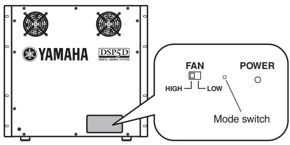
2 Between one and three of the front panel IN/OUT [TX]/[RX] LEDs will light, corresponding to the machine ID number (1-3).
One LED (OUT [TX]) is lit to indicate machine #1 (a system consisting of only the DSP5D), two LEDs (OUT [TX]/[RX]) are lit to indicate machine #2 (the first DSP5D unit), and three LEDs (OUT [TX][RX] IN[TX]) are lit to indicate machine #3 (the second DSP5D unit) is selected.
- For machine ID #1
![YAMAHA PM5D-RH - Between one and three of the front panel IN/OUT [TX]/[RX] LEDs will light, corresponding to the machine ID number (1-3). - 1](/content/2025/01/115055/images/3d419c88d4b06caf5b849f9ecf56e0916721296b0916625040838c611c99fab2.jpg)
CASCADE
- For machine ID #2
![YAMAHA PM5D-RH - Between one and three of the front panel IN/OUT [TX]/[RX] LEDs will light, corresponding to the machine ID number (1-3). - 2](/content/2025/01/115055/images/a55845d47030d4c39e8355ad402c23309d27de244fc539e1779bd611c35a7f3b.jpg)
CASCADE
- For machine ID #3
![YAMAHA PM5D-RH - Between one and three of the front panel IN/OUT [TX]/[RX] LEDs will light, corresponding to the machine ID number (1-3). - 3](/content/2025/01/115055/images/9082ca213fb1b31f68bd1afa1a67d561ec32eaecf488325b4d6a606a53f4bc62.jpg)
CASCADE
3 While the machine ID number LEDs are lit (within five seconds), you can repeatedly press the mode switch to cycle through machine ID # 1 # 2 # 3 # 1 # 2 # 3
Note
The machine ID number LED indication will return to the normal display when you have not pressed the mode switch for five seconds or more.
Making settings from DSP5D Editor
1 Synchronize DSP5D Editor with the DSP5D itself.
2 In the Mixer Setup window, use Cascade Connection to specify the machine ID number.
Note
For details, refer to the DSP5D Editor Owner's Manual.
Basic settings for cascade connection
Here we will explain the basic settings needed when cascade-connecting the PM5D and DSP5D, and when cascade-connecting two PM5D units bi-directionally.
Cascade-connecting the PM5D and DSP5D
1 In the DISPLAY ACCESS section, repeatedly press the [SYS/W.CLOCK] key until the MIXER SETUP screen appears.
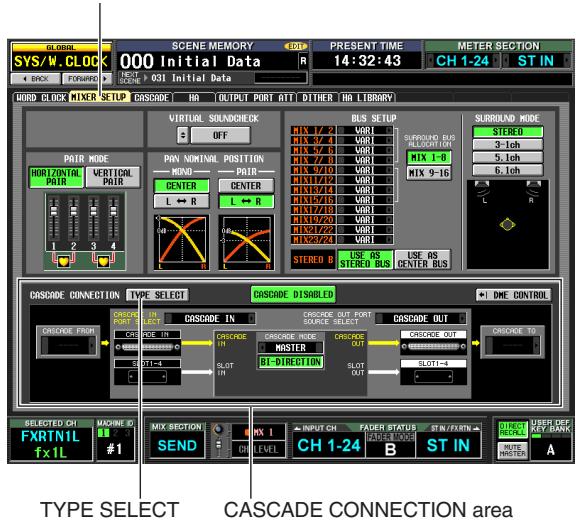
MIXER SETUP
2 In the CASCADE CONNECTION area located at the bottom of the screen, click the TYPE SELECT button to access the CASCADE TYPE SELECT window.
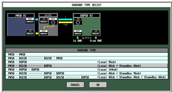
3 According to the DSP5D or DCU5D that is connected, select the appropriate connection type, and click the OK button to close the window.
According to the type you selected, a connection diagram is shown in the CASCADE CONNECTION field, and cascade settings such as ports will be made automatically.
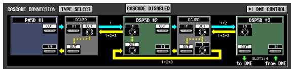
Hint
For details on each connection type, refer to p.223.
Cascade master (bi-directional cascade connections between PM5D units)
1 In the DISPLAY ACCESS section, repeatedly press the [SYS/W.CLOCK] key until the MIXER SETUP screen appears.
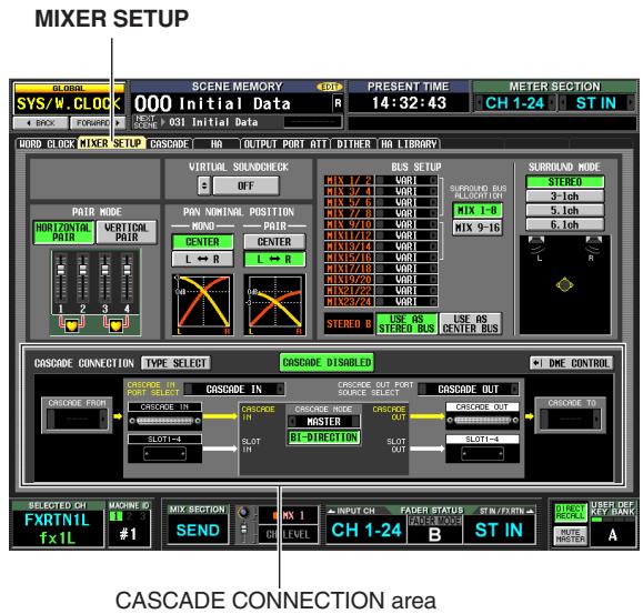
2 In the CASCADE CONNECTION area located at the bottom of the screen, click the TYPE SELECT button to access the CASCADE TYPE SELECT window.
3 Select "PM5D - PM5D" as the connection type, and click the OK button to close the window.
4 In the CASCADE MODE area at the lower part of the screen, select "MASTER". In addition, turn on the BI-DIRECTION button located immediately below it.
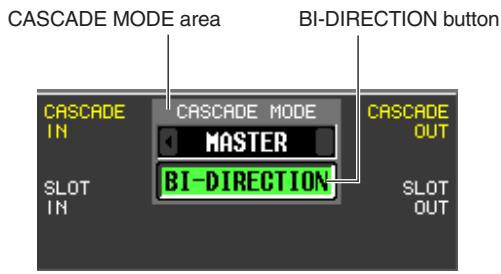
When multiple PM5D units are cascaded, the settings of the CASCADE MODE area specify whether the unit will operate as a cascade master (when "MASTER" is selected) or as a cascade slave (when "SLAVE" is selected).
If you turn the BI-DIRECTION button on, the mixed audio signals of both cascade-connected PM5D units will be output from both units.
5 Select "PM5D" in the CASCADE FROM field and in the CASCADE TO field.
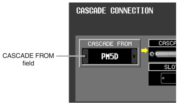
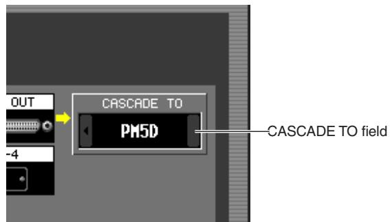
In the CASCADE FROM field, select one of the following as the type of the external device that is sending signals to the PM5D via the cascade connection.
| Display | Source device | Selectable cas-cade input port | Parameter linkage |
| — | Cascade dis-abled | CASCADE IN, SLOT 4, SLOT 3/4, SLOT1-4 [CH1-8], SLOT 1-4 [CH9-16] | Not possible |
| PM5D | another PM5D | CASCADE IN | Possible*1 |
| DM2000 /02R96 | Yamaha DM2000 or 02R96 | CASCADE IN | Not possible |
| MIXER [30BUS] | A mixer other than the above (maximum 30 bus) | SLOT 3/4, SLOT 1-4 [CH1-8], SLOT 1-4 [CH9-16] | |
| MIXER [16BUS] | A mixer other than the above (maximum 16 bus) | SLOT 4 |
*1. Linked parameters are specified in the CASCADE screen.
In the CASCADE TO field, select either "PM5D" or "--" (transmission disabled) as the external device to which the signal will be sent from the PM5D via the cascade connection.
6 Make sure that "CASCADE IN" is selected for the CASCADE IN PORT SELECT field, and "CAS-CADE OUT" is selected for the CASCADE OUT PORT SOURCE SELECT field.
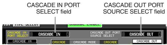
The CASCADE IN PORT SELECT and CASCADE OUT PORT SOURCE SELECT fields select the ports
through which audio signals will be transmitted to and received from the cascade-connected external device. If "PM5D" or "DM2000/02R96" are selected as the other cascade-connected device, only "CASCADE IN" can be selected for the CASCADE IN PORT SELECT field. In the CASCADE OUT PORT SOURCE SELECT field, you can choose from the output channels of slots 1-4 as well as "CASCADE OUT" (p.225).
Hint
If you choose a setting other than "CASCADE OUT" in the CASCADE OUT PORT SOURCE SELECT field, the same signal will be output from both the specified slot/channel and from the CASCADE OUT connector.
Cascade slave (bi-directional cascade connections between PM5D units)
1 In the DISPLAY ACCESS section, repeatedly press the [SYS/W.CLOCK] key to access the MIXER SETUP screen.
2 In the CASCADE CONNECTION area located at the bottom of the screen, click the TYPE SELECT button to access the CASCADE TYPE SELECT window.
3 Select "PM5D - PM5D" as the connection type, and click the OK button to close the window.
4 In the CASCADE MODE area at the lower part of the screen, select "SLAVE". In addition, turn on the BI-DIRECTION button located immediately below it.
5 Select "PM5D" in the CASCADE FROM field and in the CASCADE TO field.
6 Make sure that "CASCADE IN" is selected in the CASCADE IN PORT SELECT field, and "CAS-CADE OUT" is selected in the CASCADE OUT PORT SOURCE SELECT field.
Selecting the buses used for cascade connection
Here we will explain how to select the buses used for the cascade connection, specify the items that will be linked, and enable the cascade connection. Perform the following steps on both the cascade master and cascade slave units.
1 In the DISPLAY ACCESS section, repeatedly press the [SYS/W.CLOCK] key until the CASCADE screen shown below appears.
![YAMAHA PM5D-RH - In the DISPLAY ACCESS section, repeatedly press the [SYS/W.CLOCK] key until the CASCADE screen shown below appears. - 1](/content/2025/01/115055/images/51fa0805519ef90beb485f0a2b49e861eef3ddbdc6619fe26969579da6c2c86d.jpg)
In this combination you can enable/disable buses used for transmission/reception in the cascade connection, and select the operations that will be linked when multiple PM5D units are cascade-connected.
Note
In the case of a system that is cascade-connected to the DSP5D, the system will always operate as though the CASCADE LINK area's LINK button is on; this setting cannot be changed.
2 In the CASCADE LINK area at the left of the screen, turn on the buttons for the operations that you want to be linked.
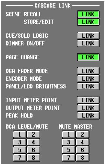
The settings of the CASCADE LINK area select the operations that will be linked when multiple PM5D units are cascade-connected. You can select the following items.
- SCENE RECALL
-
Scene recall operations / Recall undo operations
-
SCENE STORE/EDIT
Scene store operations, store undo operations, title editing, sorting
- CUE/SOLO LOGIC
Cue/Solo operations
- DIMMER ON/OFF
Dimmer effect (including talkback dimmer)
PAGE CHANGE
Switching the display screen
DCA FADER MODE
Switching the mode of the top panel FADER MODE section
- ENCODER MODE
Switching the mode of the top panel ENCODER MODE section
- PANEL/LCD BRIGHTNESS
BRIGHTNESS settings in the PREFERENCE 2 screen (UTILITY function)
- INPUT METER POINT/OUTPUT METER POINT/ PEAK HOLD
Input channel / output channel metering point selection, and peak hold on/off
DCA LEVEL/MUTE
DCA group 1-8 level, name, [CUE] key on/off operations, and [MUTE] key on/off operations
MUTE MASTER
Mute group 1-8 on/off
Note
- Note that linking is enabled only if the LINK buttons for the same item are turned on for both the cascade master unit and the cascade slave unit.
- If you have cascade-connected three or more PM5D units in a daisy-chain, you can also turn linking off for the cascade master but on between the cascade slaves.
Hint
DCA and MUTE parameter values will be linked as soon as linking is turned on. CUE/SOLO will be initialized as soon as linking is turned on. Other parameters will be linked only when that parameter is first operated after Link is turned on.
3 In the CASCADE I/O ASSIGN VIEW area, use the CASCADE IN and CASCADE OUT ON/OFF buttons to specify whether each bus will transmit or receive audio signals to or from the external cascade-connected device.
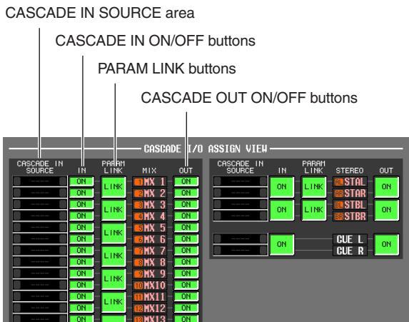
The CASCADE IN and CASCADE OUT ON/OFF buttons specify whether signals of each bus will be transmitted to or received from the cascade-connected external device. These settings are made independently for each bus; MIX buses 1-24, STEREO A bus L/R, STEREO B bus L/R, and CUE bus L/R.
Buses whose CASCADE IN button is on will receive signals from the external device; buses whose CASCADE OUT button is on will send signals to the external device.
The CASCADE IN SOURCE fields indicate each of the source buses. If the other cascade-connected device is a PM5D or DSP5D, these assignments are fixed and cannot be modified.
Note
- When two PM5D units are cascade-connected, signal transmission and reception is enabled if the CASCADE OUT button of the transmitting unit and the CASCADE IN button of the receiving unit are both turned on for the same bus.
- If a device other than the PM5D/DSP5D is selected as the other cascade-connected device, the transmission source indication shown in the CASCADE IN SOURCE field will change (→ p.227).
4 Using the PARAM LINK ON/OFF button located in the CASCADE I/O ASSIGN VIEW area, specify whether channel parameters will be linked between machines.
You can specify this for every two adjacent odd-numbered/even-numbered channels. Turn this on if you want each machine to output the same signal.
5 Set the CASCADE ENABLED/DISABLED button to ENABLED.
When you click the DISABLED button, it may take up to 10 minutes for cascade connection to be enabled.
The cascade connection will be enabled when the CASCADE ENABLED/DISABLED button is set to ENABLED on both the cascade master and the cascade slave.
Note
If the word clock becomes unlocked while the machines are synchronized (before cascade connection is enabled), the operation of each machine may become unstable. If this occurs, please power-cycle each machine.
Connecting the PM5D to your computer via USB
The PM5D Editor application can be installed in a computer and used to control the PM5D's parameters or to backup and restore the contents of the PM5D's memory.
Here we will explain the operations required in order to establish a USB connection between the PM5D and a computer.
Note
The following procedure assumes that the PM5D Editor program and USB-MIDI driver have already been correctly installed in the computer. Before you continue, download the program and driver from the Yamaha website and install them. http://www.yamahaaproaudio.com/
1 In the DISPLAY ACCESS section, repeatedly press the [MIDI/REMOTE] key until the MIDI SETUP screen appears.
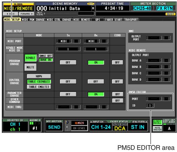
MIDI SETUP
2 In the PM5D EDITOR area at the lower right of the screen, select the port to which the computer is connected, and select the PM5D's ID number.
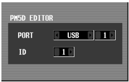
First use the PORT field to select the port that will be used to communicate with the computer. Click the 4 / 5 buttons located at the left and right of the left box to select the type of port, and press the [ENTER] key (or click inside the box) to finalize your selection. If you select USB or SLOT 1-4, use the box at the right to select a port number 1-8.
Next, use the ID field to select an ID number in the range of 1-8 for the PM5D that you want to control. (This number is used to distinguish individual PM5D units when multiple units are being used together.)
Note
Set the USB port number and PM5D ID number to match the settings in the PM5D Editor. For details, refer to the PM5D Editor owner's manual.
3 Start up PM5D Editor on the computer, and use a USB cable to connect the computer to the PM5D.
This enables communication between the computer and the PM5D. For details on operation, refer to the PM5D Editor owner's manual.
Note
- If you disconnect or reconnect the USB cable, or power-cycle the PM5D, you must close the PM5D Editor and shut down the computer. In some cases, it may not be possible to reconnect with the PM5D until the computer is restarted.
- Use a USB cable no longer than 3 meters. Also, connect the PM5D directly to the USB connector of the computer; do not use a USB hub.
Caution when using the USB TO HOST connector
You must observe the following points when connecting the PM5D to your computer via the USB TO HOST connector. If you fail to observe these points, your computer or the PM5D may stop operating ("hang up"), causing data to be corrupted or lost. If the computer or the PM5D stops working, turn the power off and then on again, and restart the computer.
- Before connecting the computer via the USB TO HOST connector, disable the power management mode (suspend/sleep/standby/hibernate) on your computer.
- Connect the USB TO HOST connector to the computer before you power-on the PM5D.
- Close all application programs (such as PM5D Editor) before turning the PM5D's power on or off, or connecting or disconnecting the USB cable.
- Leave an interval of at least three seconds between powering the PM5D on and off, or between disconnecting and connecting the USB cable.
You can use the DSP5D Editor program installed in your computer to control the DSP5D's parameters and to back up and restore the contents of its memory.
Here we will explain the necessary steps for using an Ethernet cable to connect the DSP5D to your computer.
Note
- The following steps assume that the DSP5D Editor program and DME-N Network driver have been correctly installed in your computer. Before you continue, download the program and driver from the Yamaha website and install them. http://www.yamahaaproaudio.com/
- For details on settings when using the DSP5D by itself, refer to the DSP5D Editor Owner's Manual. If you do not know the network settings, you can initialize the internal memory ( p.160) to return the settings to the default values listed in step 3.
1 In the DISPLAY ACCESS section, repeatedly press the [UTILITY] key to access the PREFER-ENCE 2 screen.
![YAMAHA PM5D-RH - In the DISPLAY ACCESS section, repeatedly press the [UTILITY] key to access the PREFER-ENCE 2 screen. - 1](/content/2025/01/115055/images/d2d7ce840cc2d9fe0eed470a1ef59ab1a678fe21b54e2027679b81d1ccf77ff7.jpg)
2 In the NETWORK area at the lower right of the screen, click the SET button to access the NETWORK window.
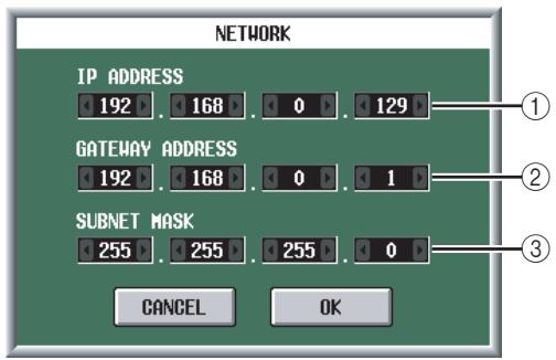
① IP ADDRESS
This specifies the number (IP address) that is assigned in order to distinguish individual devices within the Internet or LAN (Local Area Network). Set this so that it does not conflict with other devices on the network.
② GATEWAY ADDRESS
This specifies a number (gateway address) that distinguishes devices (gateway) that convert data between different media or protocols to allow communication
within the network. Set this so that it does not conflict with the IP address of other devices on the network.
(3) SUBNET MASK
Within the IP address used in the network, this defines the bits that are used for the network address that distinguishes the network.
3 Specify the IP address, gateway address, and subnet mask by clicking the 1 / 2 buttons located at the left and right of each box.
If you're connecting the DSP5D and your computer in a one-to-one connection, we recommend that you use the following default values.
IP address 192.168.0.129
Gateway address 192.168.0.1
- Subnet mask 255.255.255.0
4 Click OK to close the NETWORK window.
5 Make network settings on your computer.
For the case of the example shown above, set the IP address in the range 192.168.0.2-127, and set the gateway address and subnet mask to the same value as the DSP5D.
6 Use an Ethernet cable to connect the computer and the DSP5D, and start up DSP5D Editor on your computer.
This will allow communication between your computer and the DSP5D. For specific operating procedures, refer to the DSP5D Editor Owner's Manual.
Initializing the PM5D's internal memory
If an error occurs in the PM5D's internal memory, or if you are unable to return to normal operation because you have forgotten the system password, use the following procedure to initialize the internal memory.
!
When you initialize the internal memory, the content that had been previously been saved in memory (including read-only scene memories) will be lost. You must use extreme caution when performing this operation.
1 While holding down the SCENE MEMORY [STORE] key of the panel, turn on the power of the PW800W power supply.
After the opening screen, the following initialization menu screen will appear.
![YAMAHA PM5D-RH - While holding down the SCENE MEMORY [STORE] key of the panel, turn on the power of the PW800W power supply. - 1](/content/2025/01/115055/images/ddf27238a71b0a965b8423afcef88aa6052e84fcfc5f337426254488dd52f73a.jpg)
2 Click one of the following buttons to select the desired type of initialization.
- INITIALIZIZE ALL MEMORIES
All memories including scene memories and libraries will return to their factory-set condition.
- INITIALIZERCURRENT MEMORIES
- Memories other than scene memories and libraries will return to their factory-set condition.
- CANCEL
The initialization procedure will be aborted, and the PM5D will start up in normal operating mode.
Note
Note
If the voltage of the backup battery runs low, or if an error occurs in the internal memory, a warning message will appear at the bottom of the screen, and the initialization menu will appear "by force." Please note that if the warning message is displayed, and you click the CANCEL button to start in normal operating mode, we cannot guarantee that the system will operate correctly.
3 A message will ask you to confirm that you really want to initialize; click the OK button.
When the internal memory has been initialized, the PM5D will start up in normal operating mode.
Initializing the DSP5D's internal memory
If an error occurs in the DSP5D's internal memory, or if you are unable to connect from your computer because you've forgotten the network settings, you can use the following procedure to initialize all of the DSP5D's memory (including scene memories, libraries, and network settings) to the factory-set condition.
#
When you initialize the internal memory, the content that had been previously been saved in memory (including read-only scene memories) will be lost. You must use extreme caution when performing this operation.
1 While holding down the rear panel Mode switch, turn on the power.
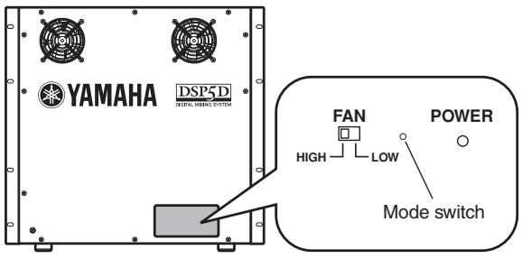
The four front panel IN/OUT [TX]/[RX] LEDs will light.
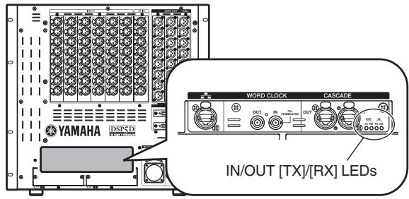
2 When the four LEDs light, release the Mode switch, and then press and hold the Mode switch once again for about five seconds.
The four LEDs will return to their normal lit state.
3 After the LEDs return to their normal lit state, release the Mode switch and wait for about twenty (20) seconds to three (3) minutes.
The four LEDs will light up consecutively starting from the left.
4 Verify that the OUT [TX] LED at left is blinking and that the other three LEDs light up steadily.
5 Turn the power off, and then on again.
The entire contents of memory (including the scene memories, libraries, and network settings) were reset to the factory state in step 4, but you must be sure to power-cycle the unit in order to return it to normal operation.
Depending on the conditions of use, discrepancies may occur in the behavior of the motor faders. you can use the Calibration function to correct such discrepancies. If necessary, you can also make fine adjustments to the analog input/output gain.
1 While holding down the [ENTER] key of the panel, turn on the power of the PW800W power supply.
After the opening screen, the following calibration menu screen will appear.
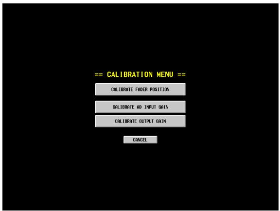
2 Click one of the following buttons to choose what you want to calibrate.
A window for the calibration item you selected will appear.
| CALIBRATE FADER POSITION | The FADER CALIBRATION win-dow will appear, allowing you to calibrate the specified faders. |
| CALIBRATE AD INPUT GAIN (make fine adjust-ments to the analog input gain; PM5D-RH model only) | The AD INPUT TRIM window will appear, allowing you to make fine adjustments to the gain of the specified analog input port. |
| CALIBRATE OUTPUT GAIN (make fine adjust-ments to the output ports) | The OUTPUT TRIM window will appear, allowing you to make fine adjustments to the gain of the specified output port. |
3 Make calibration settings as directed by the instructions that appear in the window.
4 Click the OK button in the window.
The calibration settings will be applied, and the PM5D will start up in normal mode.
Calibrating the faders
Here you can execute a semi-automatic procedure for calibrating the faders of the specified channel strip (INPUT, DCA, STEREO A/B, ST IN/FX RTN). This window will also appear if a problem with the fader settings is detected when the PM5D is started up.
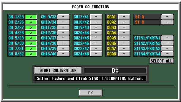
1 Click a fader select button to add a check mark to the faders you want to calibrate.
If problems with certain faders were detected during start-up, those buttons will be on (green), and check marks will already be shown for them.
2 Click the START CALIBRATION button; calibration will begin automatically.
A progress bar will indicate the state of the process.
3 The automatic processing will end when the progress bar reaches 60% . Manually move all faders you specified for calibration to the positions listed below in the following order:
① -∞
② -20 dB
③ 0 ~dB
④ +10 dB
4 After you have set the faders to the correct position, press the [ENTER] key.
Processing will proceed to the next fader position.
5 Repeat steps 3-4 for each fader position ① - ④
6 Verify that calibration has been completed and that all fader select buttons are now off. Then click the OK button.
The calibration settings will be stored in internal memory. If a fader select button remains on (green), calibration has failed. Try executing calibration once again.
Note
The progress bar will indicate "Writing..." while the settings are being written to internal memory; do not turn off the power while this indication is visible.
Adjusting the analog input gain (PM5D-RH model only)
If necessary, you can make fine adjustments in steps of 0.1 dB to the gain of the specified analog input port. Since the input levels of all ports are set to match each other when the PM5D is shipped from the factory, you will normally not need to change these settings.
Note
- Since these are set to optimal values at the factory, the default values will differ between input ports. Initializing the internal memory will return these settings to their factory-set values.
- Fine adjustments of the DSP5D's input/output gain should be made from DSP5D Editor.
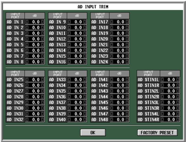
To adjust the gain, click the 4 / 6 buttons located at the left and right of each box to specify the gain of each input port in 0.1 dB units. If you want to restore all input ports to their factory settings, click the FACTORY PRESET button. Click the OK button to apply the settings.
Adjusting the output gain
If necessary, you can make fine adjustments in steps of 0.01 dB to the gain of the specified output port. The factory setting is 0.00dB
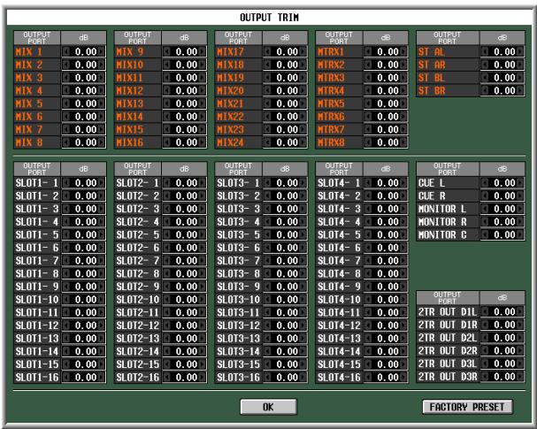
To adjust the gain, click the 1 / 2 buttons located at the left and right of each box to specify the gain of each output port in 0.01 dB units. If you want to reset all output ports to 0.00 dB, click the FACTORY PRESET button. Click the OK button to apply the settings.
Reference section
The Reference section explains the functionality and operations for every screen of the PM5D, organized into four main areas; function menu, global functions, output functions, and input functions.
Information shown in the display
The following illustration is a typical screen on the PM5D.
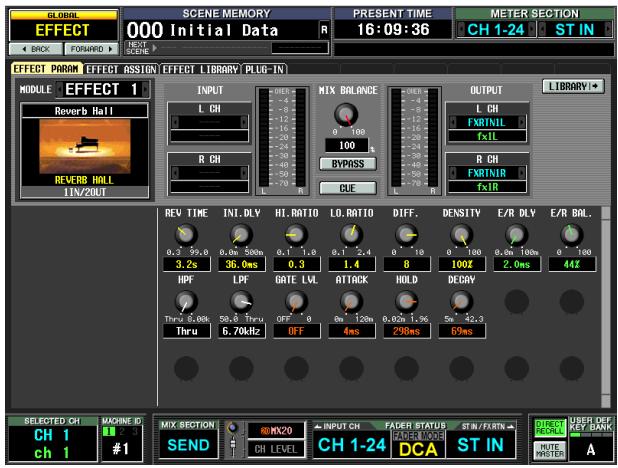
This screen shows the following information.
Upper part of the display (always visible)
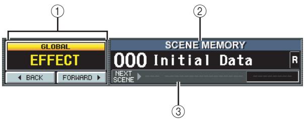
① Function Name Indication
Displays the name of the function currently selected in the screen. By clicking the BACK/FORWARD buttons you can move through the eight most recent screens that were displayed for at least two seconds (with the exception of function menus). You can also access the Function menu by clicking this function name indication. When the Function menu is displayed, click once again to return to the previously-displayed screen.
② SCENE MEMORY
Indicates the number and title of the last-stored or recalled scene memory. If you select a different scene, the number and title will blink. If you edit the contents of a scene after storing it, the EDIT indicator in the upper right will light. If the scene is write-protected, a lock icon is displayed at the right of the title, and read-only scenes are indicated as "R."
Note
- You can move the cursor to the scene number and turn the [DATA] encoder to select a scene.
- If you click here while the number and title are blinking, the most recently stored or recalled scene will be displayed.
(3) NEXT SCENE/NEXT EVENT
Indicates the scene/event that will be recalled next by the User Defined keys or the Event List function. The information shown here will differ as follows, depending on the settings in the EVENT LIST screen of the SCENE function.
- If the DISABLE button is turned on in the EVENT LIST screen
Indicates the number and name of the next scene (the scene that will be recalled when you press a User Defined key assigned to the "INC RECALL" function). Normally, this will be the scene of the number following the most recently recalled or stored scene.
- If the ENABLE [ALL MANUAL] button or the [ENABLE] button is turned on in the EVENT LIST screen
Indicates the number and name of the next event (the scene that will be recalled next by the Event List function). At the right is displayed the time until the next event will be recalled (or the condition upon which the event will be recalled).
Note
- The "MANUAL" indication means that the user must execute the Next Event operation in order to recall the next event. (Press a User Defined key assigned to the "NEXT EVENT RECALL" function, or click the NEXT button in the EVENT LIST screen.)
- If a time is displayed, this indicates the remaining time until the next event is recalled automatically.
- The "--------" indication means that there is no event to be recalled next.
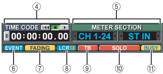
(4) PRESENT TIME, TIME CODE, CASCADE/Fs
Click this area to cycle through the following three items of information. This is linked with the UPPER PART DISPLAY setting in the PREFERENCE 2 screen (UTILITY function).
- PRESENT TIME
Indicates the present time. The time can be specified in the UTILITY function PREFERENCE 1 screen.
TIME CODE
Indicates the internal time code being generated by the PM5D (machine #1), or the time code being received from an external device. This is the same as the time code shown in the SCENE function EVENT LIST screen.
- CASCADE/Fs
Indicates the master/slave status when using a cascade connection, and the sampling frequency at which the PM5D system is currently operating.
⑤ METER SECTION
Indicates the type of channels that are currently shown by the meters in the upper left and right of the panel. You can also click the / buttons to switch this directly.
⑥ EVENT indicator
The EVENT indicator is displayed here if the ENABLE [ALL MANUAL] or ENABLE button is turned on in the SCENE function EVENT LIST screen.
⑦ FADING/TRACKING indicator
This area shows the FADING indicator while fade time is being executed, or the TRACKING indicator if Tracking Recall is available. If both are enabled, FADING takes priority.
LCR/LCR [B] indicator
If there is at least one channel for which LCR is turned on, the LCR indicator is displayed here.
If in the SYS/W.CLOCK function MIXER SETUP screen the BUS SETUP setting STEREO B is set to USE AS CENTER BUS, the LCR [B] indicator is displayed here.
⑨ TB/OSC/DIMM indicator
If talkback, oscillator, or dimmer are on, the respective TB/OSC/DIMM indicator is displayed here. If more than one of these are enabled, the display priority is TB>OSC>DIMM.
SOLO/INPUT CUE/DCA CUE/OOUTPUT CUE/ KEY IN CUE/EFFECT CUE/EXTERNAL CUE indicator
If Solo or Cue Monitor is enabled, the corresponding indicator is shown here. If more than one Cue is selected, only the indicator for the currently-valid Cue is shown.
BUSY/RS422/HA/GPI/MIDI indicator
The BUSY indicator is shown here while internal memory or a PC card in the card slot is being accessed. When RS422/HA/GPI/MIDI signals are received (in the case of RS422, when Status is received to indicate a status change on a connected device), the appropriate indicator will appear briefly. If more than one of these conditions occur simultaneously, the display priority is BUSY>RS422>HA>GPI>MIDI.
Note
In the case of MIDI signals, the indicator will light if signals are received at the MIDI connector, USB connector, or slots 1-4. However, active sensing, MIDI clock, and quarter time code messages will not cause the indicator to light.
Main area of the display
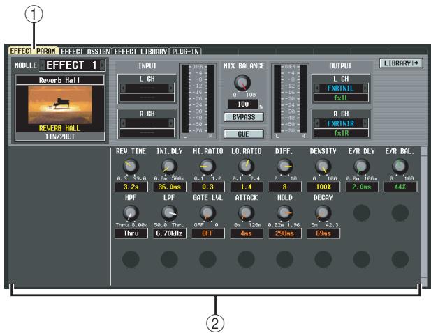
① Tabs
Click this area to switch between screens within the selected function.
② Function parameters
This area shows parameters for the currently selected function or screen.
Lower part of the display (always visible)
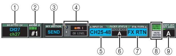
① SELECTED CH (Selected channel)
Indicates the type and name of the channel currently selected by the [SEL] key. You can also move the cursor and turn the [DATA] encoder to change this directly.
② MACHINE ID
If the DSP5 is cascade-connected, this indicates the machine (PM5D or DSP5D) #1--#3 that is being controlled from the panel. You can also move the cursor and turn the [DATA] encoder to change this directly. When you switch machines, the screen background color and the constantly displayed screen (except for time code) will also change to the settings of the machine that is now being controlled. The screen background color can be specified for each machine in the UTILITY function PREFERENCE 2 screen. The indicator above will light only for the machine ID number that is cascade-connected.
③ MIX SECTION
Indicates the encoder mode currently selected in the MIX section. In MIX SEND mode this indicates "SEND," in MIX MASTER mode this indicates "MASTER," and if a shortcut operation has been used to select TO MATRIX mode this indicates "TO MATRIX." You can also move the cursor and turn the
[DATA] encoder to directly switch between "SEND" and "MASTER."
④ Encoder/Fader mode
Indicates the parameters that are assigned to the encoders/faders of the input channel strip.
The encoders can be assigned to MIX SEND 1-24, GAIN, ATT, PAN/BAL, LEVEL, or REMOTE. The faders can be assigned to LEVEL, MIX SEND 1-24, or REMOTE. For both the encoders and the faders, for parameters other than REMOTE, you can move the cursor and turn the [DATA] encoder to switch them directly.
If you select LEVEL for the encoders, the faders will be flipped; the most recently selected of the MIX SEND 1-24 parameters will be assigned to the faders. Similarly, the faders will also be flipped if you select MIX SEND 1-24 for the faders; the LEVEL parameter will be assigned to the encoders.
⑤ INPUT CH (Input channel) layer
This shows the layer that is selected for the input channel strip in tandem with the [CH 1-24]/[CH 25-48] keys located in the input channel strip of the panel or the FADER MODE [A]-[F] keys of the FADER MODE section. (If the MIDI REMOTE layer is selected, this will indicate REMOTE 1-24.) For layers other than MIDI REMOTE, you can move the cursor and turn the [DATA] encoder to select them directly.
(6) FADER MODE
This is linked with the FADER MODE section on the panel, and indicates the function that is assigned to the faders of the DCA strip. You can also move the cursor and turn the [DATA] encoder to change this directly.
⑦ ST IN/FX RTN (ST IN channel / Effect return) layer
This shows the layer that is selected for the ST IN channel strip in tandem with the [ST IN] key / [FX RTN 1-4] key located in the ST IN channel strip of the panel or the FADER MODE [A]-[F] keys of the FADER MODE section. (If the MIDI REMOTE layer is selected, this will indicate REMOTE 25-28. If a layer of a machine other than the input channel layer is selected, the machine ID number is also shown.) For layers other than MIDI REMOTE, you can move the cursor and turn the [DATA] encoder to select them directly.
(8) DIRECT RECALL/MUTE MASTER
This switches between the following two choices as the function of the [1]–[8] keys in the SCENE MEMORY section of the panel.
- DIRECT RECALL
Keys [1]–[8] of the SCENE MEMORY section will directly recall the scene that was assigned in the SCENE screen.
MUTE MASTER
Keys [1]–[8] of the SCENE MEMORY section will switch mute groups 1–8 on/off.
⑨ USER DEFINED KEY BANK
Indicates the currently selected bank of User Defined keys. You can also move the cursor and turn the [DATA] encoder to change this directly.
Function menu
Here you can select the function that you want to view in the display. These operate in the same way as the keys of the DISPLAY ACCESS section.
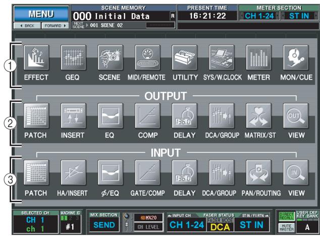
Hint
To access this screen from another function, click the Function Name area at the top of the display.
① Global functions
These buttons access functions that affect the entire PM5D.
② Output-related functions
These buttons access functions related to output channels (MIX channels, MATRIX channels, STEREO A/B channels).
③ Input-related functions
These buttons access functions related to input channels (input channels, ST IN channels, FX RTN channels).
Global functions
EFFECT functions
EFFECT PARAM (Effect parameter) screen
Here you can select the type of internal effect, edit its parameters, and perform input/output patching.
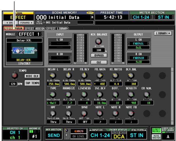
EFFECT PARAM
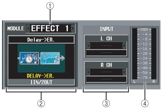
① Effect selection
Of the internal effects 1-8, select the effect for which you want to make settings. To switch between effects, place the cursor here and turn the [DATA] encoder, or click the / buttons at left or right.
② Effect type
Indicates the currently selected effect type, both by name and as a graphic. The number of input/output channels (1 IN/2 OUT or 2 IN/2 OUT) of this effect is also shown at the bottom of this area.
Note
You can't switch the effect type in this screen. If you want to switch to a different effect type, recall an effect that uses the desired effect type from the effect library.
③ Input patch
This box lets you select the signal path that will be patched to the L/R input channels of the internal effect. Move the cursor to this box and turn the [DATA] encoder or click the / buttons at left or right to display the desired signal path, and then press the [ENTER] key to finalize the change.
You can choose the following signal paths.
| MIX1-MIX24 | MIX channel 1-24 output |
| INS CH1-INS CH48 | Input channel 1-48 insert out |
| INS STIN1 (L/R)-INS STIN4 (L/R) | ST IN channel 1-4 (L/R) insert out |
| INS MIX1-INS MIX24 | MIX channel 1-24 insert out |
| INS MTRX1-INS MTRX8 | MATRIX channel 1-8 insert out |
| INS ST A (L/R) | STEREO A channel (L/R) insert out |
| INS ST B (L/R) | STEREO B channel (L/R) insert out |
| INS MON (L/R/C) (PM5D only) | MONITOR channel (L/R/C) insert out |
Note
- If you move the cursor away without pressing the [ENTER] key, the setting will revert to its original state.
- If you assign a signal to both input channels for a 1 IN/2 OUT effect type, the two will be mixed to monaural and then input.
- If you assign a signal to only one input channel for a 2 IN/2 OUT effect type, the same signal will be sent to both channels of the effect.
- If STEAL PATCH CONFIRMATION is turned on in the PREFERENCE 1 screen (UTILITY function), and you attempt to make patch settings that would cause an existing patch to be modified, a confirmation message will appear.
④ Input meter
Indicates the level of the signal being input to the effect.
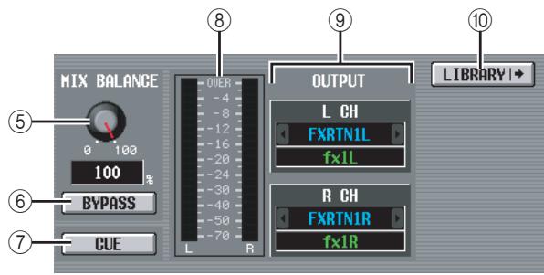
⑤ MIX BALANCE
Adjusts the balance of the effect sound relative to the original sound.
0 (%) outputs only the original sound, and 100 (%) outputs only the effect sound.
(6) BYPASS
This button temporarily bypasses the effect.
⑦ CUE
This button cue-monitors the output of the effect shown in the screen. Cue is automatically defeated when you switch to a different screen. (However, cue will be held if you switch to the EFFECT ASSIGN screen.)
⑧ Output meter
Indicates the level of the signal being output from the effect.
⑨ Output patch
This box lets you select the signal path that will be patched to the L/R output channels of the internal effect. The selection method is the same as for Input Patch. You can choose the following signal paths.
| CH1-CH48 | Input channel 1-48 input |
| STIN1-STIN4 (L/R) | ST IN channel 1-4 (L/R) input |
| FXRTN1-FXRTN4 (L/R) | FX RTN channel 1-4 input |
| INS CH1-INS CH48 | Input channel 1-48 insert in |
| INS ST1 (L/R)-INS ST4 (L/R) | ST IN channel 1-4 (L/R) insert in |
| INS MIX1-INS MIX24 | MIX channel 1-24 insert in |
| INS MTRX1-INS MTRX8 | MATRIX channel 1-8 insert in |
| INS ST A (L/R) | STEREO A channel (L/R) insert in |
| INS ST B (L/R) | STEREO B channel (L/R) insert in |
| INS MON (L/R/C) (PM5D only) | MONITOR channel (L/R/C) insert in |
Note
Even if you've patched multiple channels in the INPUT PATCH/OUTPUT PATCH function INSERT PATCH screen, changing the input/output patch in this screen will turn off patching to other channels.
⑩ LIBRARY
This button accesses the EFFECT LIBRARY screen for the currently selected effect.
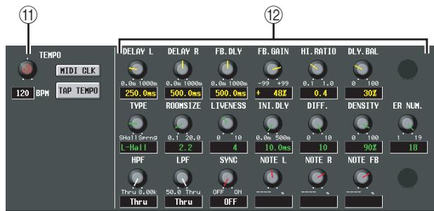
⑪ TEMPO parameter
If a delay-type or modulation-type effect type is selected, the tempo parameter will be displayed here. The TEMPO parameter specifies time-related parameters in units of BPM (Beats Per Minute). For a delay-type effect it sets the DELAY (delay time), and for a modulation-type effect it sets the FREQ. (modulation frequency).
Note
For some effect types, a parameter unique to the effect may be shown instead of the TEMPO parameter. For example if FREEZE is selected as the effect type, a button for recording/playing the input signal is shown.
The BPM value can be edited using the on-screen knob, or by repeatedly clicking the TAP TEMPO button. (In this case, the average interval between clicks is detected. If the average value is outside the range of 20-300 BPM, it will be ignored.)
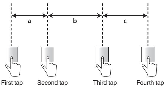
The average of the intervals is input as the parameter value (average of a, b, and c)
If the MIDI CLK button is on, the TEMPO parameter will synchronize to the MIDI timing clock being received from the MIDI port.
② Effect parameters
This area shows parameters for the currently selected effect type.
EFFECT ASSIGN screen
This screen lists the effect types used by internal effects 1-8, and shows their input levels.. Here you can also assign signals to input/output channels, and make settings for bypass and cue.
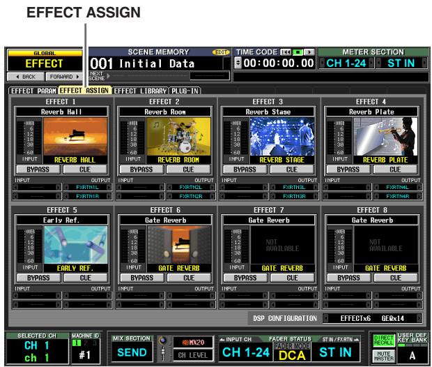
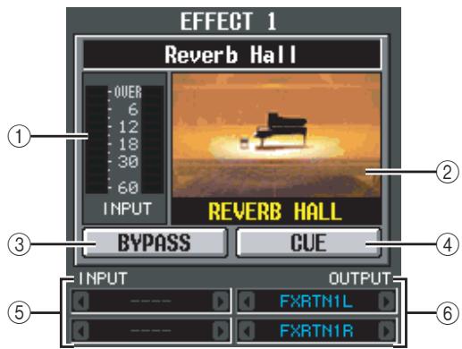
① Level meter
Indicates the input level to the effect.
② Effect type
Indicates the selected effect type, both by name and as a graphic. When you click this area, the EFFECT PARAM screen will appear. You can also drag and drop this area onto another effect in this screen to copy the effect settings.
(3) BYPASS
This button temporarily bypasses the effect.
(4) CUE
This button cue-monitors the effect output. Cue is automatically defeated when you switch to a different screen. (However, cue will be held if you switch to the EFFECT PARAM screen of the corresponding effect.)
⑤ Input patch
This box indicates the signal path that is patched to the L/R input channels of the internal effect. You can also directly assign the signal path in this box.
⑥ Output patch
This box indicates the signal path that is patched to the L/R output channels of the internal effect. You can also directly assign the signal path in this box.
Note
Even if you've patched multiple channels in the INPUT PATCH/OUTPUT PATCH function INSERT PATCH screen, changing the input/output patch in this screen will turn off patching to other channels.

⑦ DSP CONFIGURATION
This box lets you change the number of assignments for the internal effects and GEQ modules. If you decrease the number of internal effects, the number of available GEQ modules will increase by one. The number of internal effects can be changed between eight units (twelve GEQ modules) to zero available internal effects (twenty GEQ modules).
Note
If you change the DSP CONFIGURATION setting, the internal effects or GEQ modules may be muted briefly.
EFFECT LIBRARY screen
Here you can recall, store, rename, or delete items in the effect library.
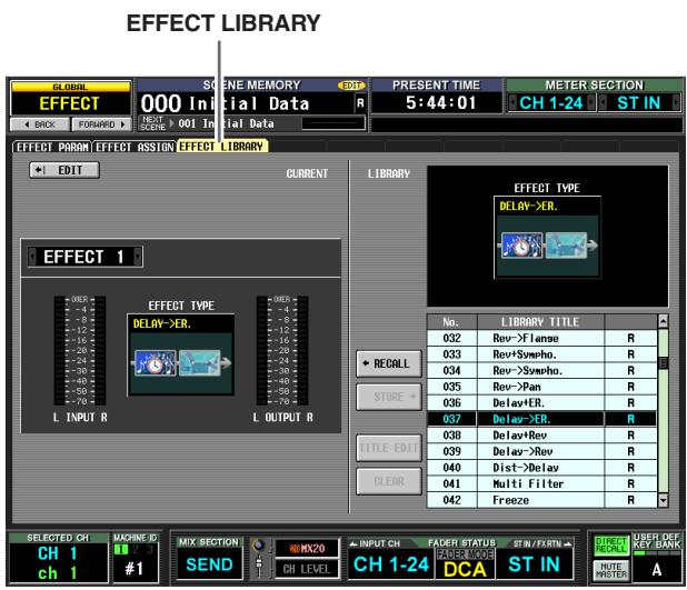
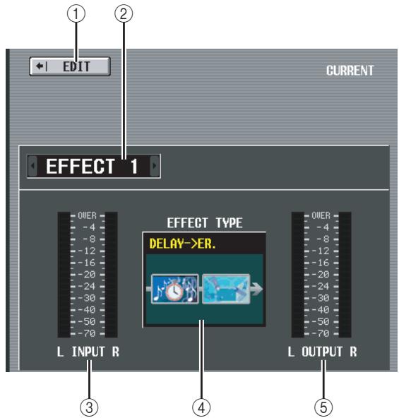
① EDIT
When you click this button, the EFFECT PARAM screen for the currently selected effect will appear.
② Effect selection
Of the internal effects 1-8, select the effect for which you want to make settings.
③ Input meter
Indicates the input level of the effect.
④ Current effect type
Indicates the effect type of the currently selected effect.
⑤ Output meter
Indicates the output level of the effect.
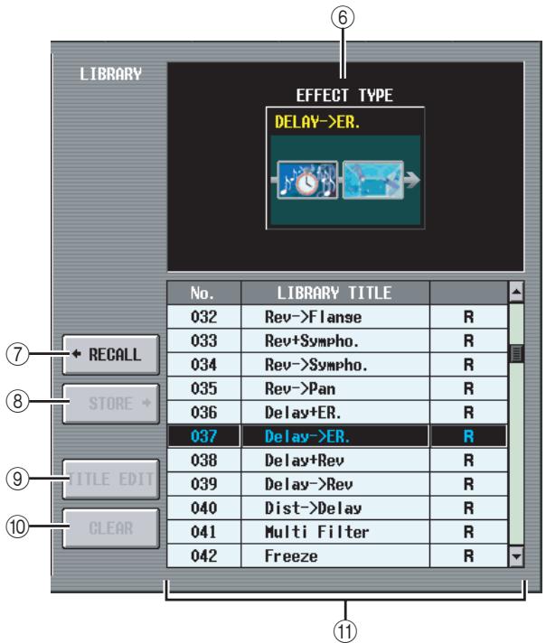
⑥ Library effect type
Indicates the effect type of the library item selected in the list.
⑦ RECALL
Recalls the library item shown in the list into the currently selected effect.
Note
When you recall an Add-On effect, other effects may be muted briefly.
(8) STORE
Stores the currently selected effect into the selected location of the list. When you click this button a window will appear, allowing you to name and save the effect.
(9) TITLE EDIT
Edits the title of the library item selected in the list. When you click this button a window will appear, allowing you to edit the title.
10 CLEAR
Deletes the library item selected in the list. When you click this button, a confirmation message will appear.
Note
Library items with an "R" displayed in the right column of the list are read-only. Read-only items cannot be stored, renamed, or deleted.
① Library list
Use the scroll bar to select the library item on which you want to perform an operation. The selected library item will move to the center, and will be highlighted.
Note
If the library item selected for operations is different than the last-stored/recalled library item, the last-stored/recalled library item will be shown with a blue background.
PLUG-IN screen
In this screen you can make settings for Waves Y96K plug-in DSP cards installed in slots 1-4. For details on operation, refer to the Y96K operating manual.
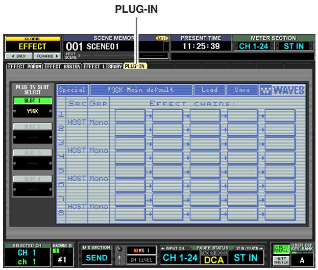
Please note that Y96K cards will operate as follows.
- Settings will be stored/recalled as scene data, but the Undo function is not supported.
- If you power the PM5D off and then on again, the conventional scene data will be in the state of when the power was turned off, but the Y96K will be in the state that was last stored or recalled.
- If you recall a scene that produces a major change in the Y96K's settings, the Y96K's settings will change several seconds after recall occurs on the PM5D. If you want to match this timing, set the appropriate START OFFSET in the FADE TIME screen.
- Do not execute scene store or recall operations while the screen indicates that the Y96K is waiting to update. If you do so, the screen will become inoperable for up to 30 seconds.
- The Y96K's settings will be saved in the PM5D when you store the scene. If in the past you had stored a scene with a Y96K installed, and you then once again store that scene without the Y96K installed, the previous Y96K settings will remain. If there is a scene for which a Y96K has never been installed, and you install a Y96K and then recall that scene, nothing will be reflected in the Y96K.
- In PREVIEW mode, the PLUG-IN screen will not show the state of the Y96K.
Note
The DSP5D does not support the Y96K.
GEQ function
GEQ PARAM (GEQ parameter) screen
Here you can adjust the boost/cut for a 31-band graphic EQ or 8-band parametric EQ, specify the input/output patching, and assign a GEQ to faders.
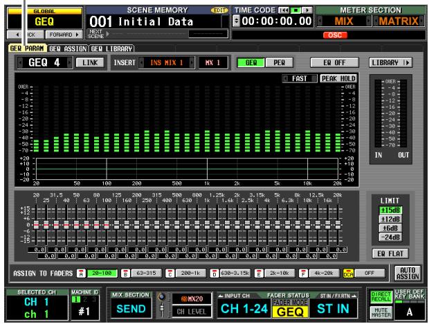
GEQ PARAM
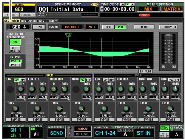
GEQ PARAM
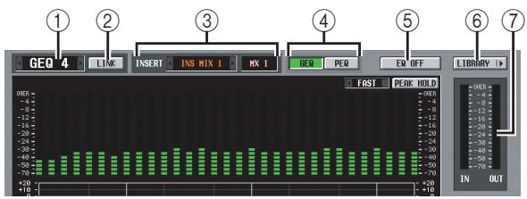
(1) Module select
This selects the GEQ module to operate. To switch between modules, place the cursor here and turn the [DATA] encoder, or click the / buttons at left or right.
② LINK button
This button links adjacent odd-numbered even-numbered graphic EQ modules. When you turn this button on, a window will appear, allowing you to select whether the parameters will be copied from one module to the other, or whether both modules will be initialized.
③ INSERT (Insert destination)
Selects the location at which the GEQ module will be inserted. Move the cursor to this box and turn the [DATA] encoder or click the / buttons at left or right to display the desired insertion destination, and then press the [ENTER] key to finalize the change. You can choose the following insertion destinations.
- INS CH1-INS CH48
Input channel 1-48 insert in/out
- INS STIN1 (L/R)-INS STIN4 (L/R)
ST IN channel 1-4 (L/R) insert in/out
INS MIX1-INS MIX24
MIX channel 1-24 insert in/out
- INS MTRX1-INS MTRX8
MATRIX channel 1-8 insert in/out
INS ST A (L/R)
STEREO A channel (L/R) insert in/out
- INS ST B (L/R)
STEREO B channel (L/R) insert in/out
INS MON (L/R/C) (PM5D only)
MONITOR channel (L/R/C) insert in/out
Note
- When you select the insertion destination here, insert in/out will be patched simultaneously, and insertion will automatically be turned on for the channel into which the graphic EQ module was inserted.
- If you move the cursor away without pressing the [ENTER] key, the setting will revert to its original state.
④ GEQ/PEQ button
This switches between the 31-band graphic EQ (GEQ) and 8-band parametric EQ (PEQ).
Note
Even if you switch between GEQ and PEQ, the graphic EQ and parametric EQ parameters will remember their settings from before the change.
⑤ EQ ON/OFF button
Switches the currently selected GEQ module on/off.
⑥ LIBRARY
This button accesses the GEQ LIBRARY screen.
⑦ Level meter
This meter indicates the peak level before and after the GEQ module.
When graphic EQ is selected
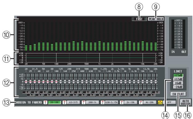
SLOW/FAST
Switches the fall speed of the spectrum analyzer between slow or fast. This setting does not affect the meters in other screens or the meters on the panel.
(9) PEAK HOLD
Switches the peak hold function on/off for the spectrum analyzer. The peak level for each band is held while this button is on. (To reset the peak level display, turn this button off and then on again). This setting does not affect the meters in other screens or the meters on the panel.
Spectrum analyzer
This is an analyzer that shows a realtime level display for each band of the input signal.
⑪ EQ graph
Indicates the current frequency response of the graphic EQ.
⑫ Faders
These faders cut/boost the frequency bands of the graphic EQ. The actual values are shown in the numerical boxes below.
⑬ ASSIGN TO FADERS
These buttons divide the 31 bands of the graphic EQ into six groups so that you can use the DCA faders to adjust the boost/cut amount of each band. Click one of the six buttons A (20.0-100), B (63.0-315), C (200-1.00k), D (630-3.15k), E (2.00k-10.0k), F (4.00k-20.0k). DCA faders 1-8 will be assigned to the corresponding region of frequency bands, allowing you to control them with the DCA faders. At this time, the divisions of the corresponding faders and the value in the numerical box screen will turn red in the screen. To return to the original state, press the DCA (OFF) button in the screen or the [DCA] button on the panel.
Note
- If the ASSIGN TO FADERS buttons A-F are off, you can hold down the [SHIFT] button on the panel and press a FADER MODE section button [A]-[F], and then use the DCA faders to control the corresponding region of the graphic EQ in the same way as if you had pressed a button A-F in the screen.
- The currently selected DCA fader mode (DCA, A-F) is disabled while one of the ASSIGN TO FADERS buttons A-F is on. At this time, you can also use the FADER MODE section buttons [A]-[F] to switch between regions of the graphic EQ; the button for the selected region will blink, and the remaining buttons will light.
- If the AUTO ASSIGN button is off, the setting in the ASSIGN TO FADERS field is cleared automatically when you switch screens, and the currently selected DCA fader mode will once again be enabled.
14 LIMIT
The range and direction of adjustment controlled by the faders can be selected from the following: ± 15 dB, ± 12 dB, ± 6 dB (these are valid in both the boost and cut directions), or -24 dB (valid only in the cut direction).
⑤ EQ FLAT
Resets all faders to the 0 dB position. When you click this button, a confirmation message will appear.
16 AUTO ASSIGN
This button automates assignments to the DCA faders. If this button is on, the most recently selected region of GEQ bands will be assigned to the DCA faders when you access the GEQ PARAM screen.
When parametric EQ is selected
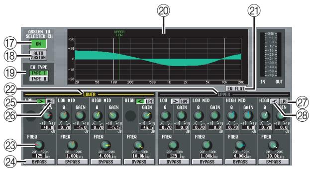
17 ASSIGN TO SELECTED CH ON/OFF button
This switches the assignment to the SELECTED CHANNEL section on/off.
Note
If the AUTO ASSIGN button is off, switching the screen will make the ASSIGN TO SELECTED CH ON/OFF button turn off, and you'll be able to use the SELECTED CHANNEL section to operate the parameters of the currently selected channel.
18 AUTO ASSIGN
This button automates assignment to the SELECTED CHANNEL section. If you leave this button turned on, the selected frequency band will be assigned to the SELECTED CHANNEL section when you access the GEQ PARAM screen if the ASSIGN TO SELECTED CH ON/OFF button is on.
19 EQ TYPE
This selects the EQ type. Turn the TYPE I button on to choose the algorithm used in conventional Yamaha digital mixers, or turn the TYPE II button on to choose a newly-developed algorithm. Using TYPE II will decrease the interference between bands.
EQ graph
This graph shows the approximate response of the EQ parameters. The colored vertical line shows the FREQ (center frequency) of the band at which the cursor is located. (The color of each line is the same as the markings around the knob of each band.) When you edit the Q or GAIN (gain) of each band, the response curve will change accordingly.
EQ FLAT
This resets the GAIN parameter of all bands to the initial value (± 0.0dB) . When you click this button, a confirmation message will appear.
^22 LOWER/UPPER
These indicators show which four bands (LOWER or UPPER) are selected in the SELECTED CHANNEL section of the panel. The text is shown in yellow to indicate the set of bands that is selected.
② Knobs
For each band, these knobs adjust the Q, the FREQ (center frequency), and GAIN (amount of boost/cut).
2 BYPASS
This button bypasses each band of the EQ.
25 (LOW shelving)
If this button is on, the LOW EQ will be switched to a shelving-type. The Q knob will disappear.
HPF (High Pass Filter)
If this button is on, the LOW EQ will operate as a high pass filter. The Q knob will disappear, and the GAIN knob will be used to turn the HPF on/off.
LPF (Low Pass Filter)
If this button is on, the HIGH EQ will operate as a low pass filter. The Q knob will disappear, and the GAIN knob will be used to turn the LPF on/off.
(28) (HIGH shelving)
If this button is on, the HIGH EQ will be switched to a shelving-type. The Q knob will disappear.
GEQ ASSIGN screen
This screen lists the approximate values of the GEQ module settings, and shows the input/output levels. The signal path assignments and on/off status can also be edited in this screen.
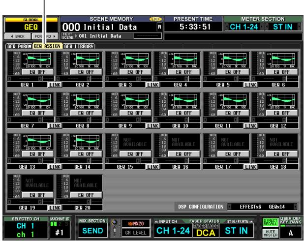
GEQ ASSIGN
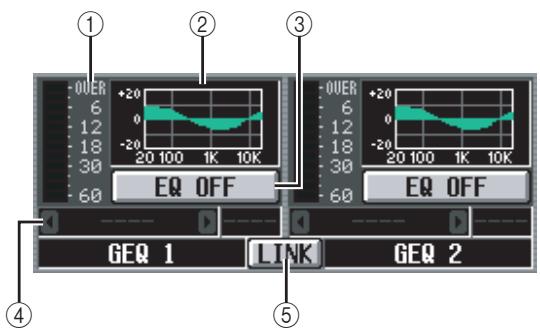
(1) Level meter
This meter indicates the peak level before and after the GEQ module.
② Fader graph
This indicates the approximate fader position for each band. When you click this area, the GEQ PARAM screen for the corresponding GEQ module will appear. You can also drag and drop this area onto another GEQ module to copy the GEQ settings.
③ GEQ ON/OFF button
Switches the GEQ module on/off.
④ Insert destination
Indicates the location at which the GEQ module is inserted. You can also specify the insert location from within this screen.
⑤ LINK button
This button indicates the link status of adjacent odd-numbered even-numbered GEQ modules. When you turn this button on, a window will appear, allowing you to select whether the parameters will be copied from one module to the other, or whether both modules will be initialized.
DSP CONFIGURATION
EFFECTx6 GEQx14
⑥ DSP CONFIGURATION
This box lets you change the number of assignments for the internal effects and GEQ modules. If you decrease the number of internal effects, the number of available GEQ modules will increase by one. The number of internal effects can be changed between eight units (twelve GEQ modules) to zero available internal effects (twenty GEQ modules).
Note
If you change the DSP CONFIGURATION setting, the internal effects or GEQ modules may be muted briefly.
GEQ LIBRARY screen
Here you can recall, store, rename, or delete items in the GEQ library.
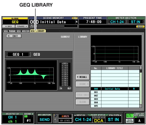
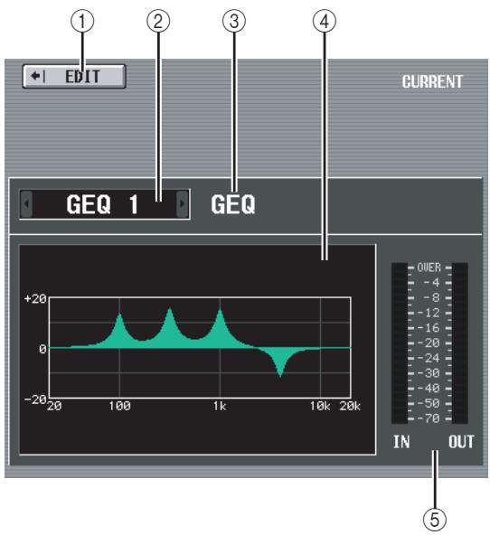
(1) EDIT
When you click this button, the GEQ PARAM screen for the currently selected GEQ module will appear.
② GEQ module select
Select the GEQ module for which you want to make settings.
③ GEQ/PEQ
This indicates the type of the selected GEQ. The library list will indicate either GEQ LIBRARY or OUTPUT EQ LIBRARY, depending on the current type.
④ Current EQ graph
Indicates the approximate response of the currently selected GEQ module.
(5) Level meter
This meter indicates the peak level before and after the GEQ module.
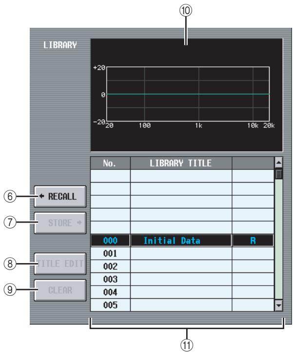
⑥ RECALL
Recalls the library item selected in the list into the currently selected GEQ module.
⑦ STORE
Stores the settings of the currently selected GEQ module into the selected location in the list. When you click this button a window will appear, allowing you to name and save the GEQ module settings.
(8) TITLE EDIT
Edits the title of the library item selected in the list. When you click this button a window will appear, allowing you to edit the title.
(9) CLEAR
Deletes the library item selected in the list. When you click this button, a confirmation message will appear.
Note
Library items with an "R" displayed in the right column of the list are read-only. Read-only items cannot be stored, renamed, or deleted.
⑩ Library EQ graph
Shows the response curve of the library selected in the list.
1 Library list
Use the scroll bar to select the library item on which you want to perform an operation. The selected library item will move to the center, and will be highlighted.
SCENE screen
Here you can store/recall scenes.
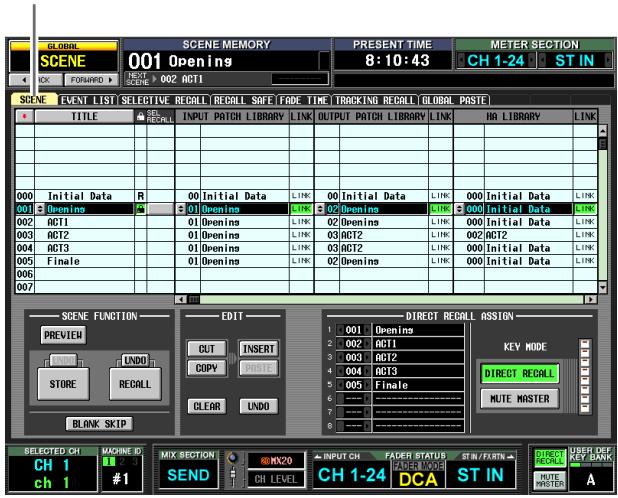
SCENE
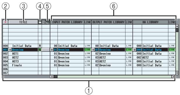
① Scene list
This is a list of the stored scenes. For each scene, the following items are displayed. (To view ⑦ COMMENT and subsequent items, scroll the list to the right.)
② (Scene number)
This is the scene number 0-500. You can click this icon to reverse the order in which the scenes are sorted.
(3) TITLE
This is the name assigned to each scene. You can click the TITLE button to sort the scenes in order of their titles. When you click the 串 button at the left, a window will appear, allowing you to edit the title.
(Protect)
For each scene, this button specifies whether the scene will be protected and read-only.
- Protect (lock) symbol
The scene cannot be overwritten.
R (read only) symbol
In addition to the above Protect setting, it will be impossible to overwrite the scene by loading a file, etc. This setting can be made only for consecutive scene numbers starting at scene number 000.
Note
- If LINKED LIBRARY PROTECTION is turned on in the UTILITY function PREFERENCE 1 screen, libraries that are linked to READ ONLY scenes will also be protected, but they will be overwritten when a file is loaded.
- Read Only settings will not be loaded. If you load after initializing the memory, you'll have to re-make the Read Only settings.
No symbol
The scene is not protected in any way.
⑤ SEL.RECALL (Selective recall)
For each scene, you can specify whether the Selective Recall function will be used when recalling the scene. If the Selective Recall function is enabled (p.180), scenes for which this button is turned on can recall only specific parameters. (Alternatively, you can exclude only specific parameters from the recall.)
If the scenes are sorted in order of TITLE, a check mark is displayed for scenes for which this is turned on. If the scenes are sorted in numerical order, a downward or upward arrow is displayed for scenes for which this is turned on; this makes it easy to see which was the original scene prior to selective recall.
⑥ Library link
This area shows the number and title of the INPUT PATCH library, OUTPUT PATCH library, and HA library used by each scene. You can click the button at the left to access a window that lets you change the library number that is linked. The LINK button for each library determines whether library recall operations will be linked to scene recall operations.
If the LINK button is on (this column indicates "LINK"), the library of the corresponding number will also be recalled when you recall that scene. A library whose LINK button is off will not change when you recall that scene.
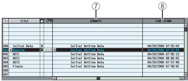
(7) COMMENT
In this column you can enter or view a comment for the scene. A text input window will appear when you move the cursor to the COMMENT field and press the [ENTER] key, or when you click the button at the left.
⑧ TIME STAMP
Indicates the time at which the scene was last stored, in the format of month/day/year/hours/minutes/seconds.
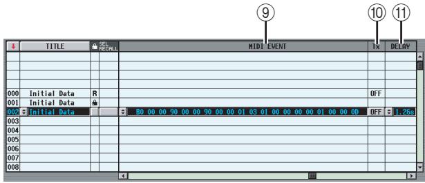
⑨ MIDI EVENT
Specifies a MIDI message that will be transmitted from the MIDI OUT connector when the scene is recalled. When you click the button at left a window will appear, allowing you to input a MIDI event in hexadecimal form (p.128).
⑩ TX ON/OFF (MIDI event transmission on/off)
Specifies whether the assigned MIDI event will be transmitted.
⑪ DELAY
This specifies the timing of the program change or MIDI event that will be transmitted when the scene is recalled. When you click the button at the left, the following MIDI EVENT DELAY window will appear.
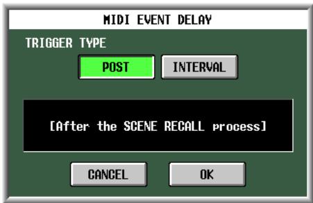
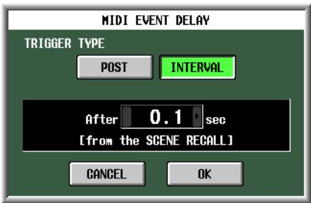
POST
The program change or MIDI event will be transmitted when scene recall processing is completed (the same operation as before V1.2).
- INTERVAL
The program change or MIDI event will be transmitted following the specified time interval after scene recall processing began. The transmission start time can be specified in a range from 0.0 seconds to 9.9 seconds.
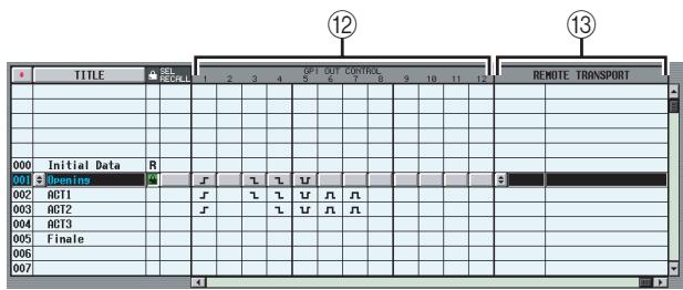
2 GPI OUT CONTROL 1-12
Specifies the polarity and transmission method (tally/ trigger) of the signal that is sent from GPI OUT ports 1-12 when the scene is recalled. When you click a button corresponding to a port 1-12, the setting will change in the following order.
| Display | Polarity | Transmission method |
| None | Disabled | |
| High active | Tally | |
| Low active | Tally | |
| High active | Trigger | |
| Low active | Trigger |
Note
- GPI OUT CONTROL settings are independent of the settings in the MIDI/REMOTE function GPI screen.
- In the case of a Trigger type setting, the time interval between becoming active and returning to the inactive state is 250 msec.
⑬ REMOTE TRANSPORT
Selects the transport command (MMC or RS422 protocol) that will be transmitted when you recall the scene. If you click the button at the left a window will appear, allowing you to select the output destination and the type of command.
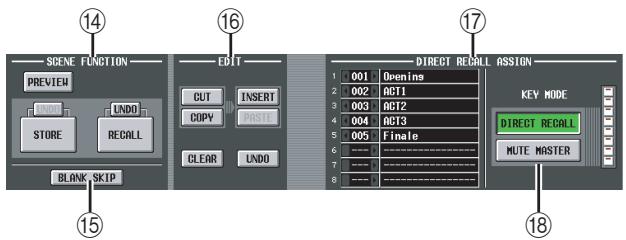
⑭ SCENE FUNCTION
Here you can store/recall scenes.
- RECALL
Loads the scene currently selected in the scene list into the PM5D.
- STORE
Saves the current settings of the PM5D in the scene currently selected in the scene list. (This button is inoperable if the selected scene is read-only or protected.)
- UNDO
Cancels the preceding Recall or Store operation. You can click this once again (Redo) to return to the state prior to Undoing.
- PREVIEW
If this button is on, the PM5D will be in PREVIEW mode; this allows you to view or edit the settings of a scene stored in memory or the settings of a library item without affecting the internal signal processing. This is linked with the [PREVIEW] key in the SCENE MEMORY section of the panel (p.88).
Note
- Monitor settings will apply to internal signal processing even during Preview mode. You can perform cue/monitor operations while Previewing.
- EVENT LIST, MIDI, and GPI operations will apply to internal signal processing, but not to Preview.
- Memory card save/load operations cannot be performed during Preview.
- During Preview, user defined operations that affect internal signal processing are disabled; such operations include EVENT LIST, TALKBACK ASSIGN, MONITOR, MIDI DIRECT OUT, MACHINE CONTROL, and GPI OUT CONTROL.
15 BLANK SKIP
Specifies how scene numbers can be selected. If the BLANK SKIP button is off, all scene numbers can be selected consecutively regardless of whether they contain scene data. In contrast if the BLANK SKIP button is on, only numbers in which a scene is actually stored can be selected. This setting applies when you switch scenes using the SCENE MEMORY [▲]/[▼] keys in the SCENE MEMORY section of the panel, the [DATA] encoder, or the l buttons in the screen.
16 EDIT
These buttons let you rearrange the order of the scenes in memory.
CUT
Cuts the scene selected in the list, and holds it in a temporary memory buffer. Subsequent scenes will be moved forward by one.
COPY
Copies the scene selected in the list into the memory buffer. The copy-source and other scenes will not be affected.
- INSERT
Inserts the scene from the memory buffer at the number selected in the list. Scenes that follow the number at which you inserted will be moved backward by one.
PASTE
Overwrites the scene from the memory buffer onto the blank number selected in the list. Other scenes will not be affected.
CLEAR
Deletes the scene selected in the list.
- UNDO
Cancels the operation that was last performed in the EDIT area.
Note
- A confirmation message will appear when you click one of these buttons.
- If a read-only or protected scene is selected in the list, the CUT, INSERT, and CLEAR buttons are grayed-out, and cannot be used.
- If an existing scene is selected in the list, the PASTE button is grayed-out, and cannot be used.
- If the list is sorted by title, the CUT, INSERT, and UNDO buttons are displayed in gray.
- If you modify the contents of a scene by operations in other than the EDIT section, the UNDO button is displayed in gray.
17 DIRECT RECALL ASSIGN
This lets you select the scenes that will be directly recalled by the SCENE MEMORY [1]–[8] keys on the panel. This function is available if the DIRECT RECALL button is on.
When you move the cursor to the field on the left and turn the [DATA] encoder, or when you click the / buttons to select a scene number, the scene name will appear in the field on the right.
18 DIRECT RECALL/MUTE MASTER
These are linked with the DIRECT RECALL/MUTE MASTER buttons shown at the bottom of the display. ( p.165)
EVENT LIST screen
The Event List function lets you register scenes in the order of use, so that these scenes can be recalled either manually or automatically according to the specified time code or interval.
Note
The setting screen for the PM5D is always shown, even if the DSP5D is cascade-connected.
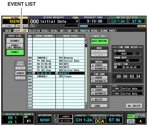
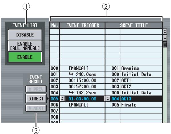
① EVENT LIST ENABLE/DISABLE
Use the following three buttons to enable/disable the Event List function.
- DISABLE
The Event List function will not recall scenes registered in the event list.
- ENABLE [ALL MANUAL]
Scenes registered in the event list will be recalled only by manual operation. If the list contains events for which a time code has been specified, the candidate event for recall will change as time code progresses, but events will not actually be recalled unless the recall operation is performed manually.
- ENABLE
Scenes registered in the event list will be recalled according to the specified condition (time code, interval, or manual operation).
② Event list
In this list you can register the scenes to be recalled, and the conditions under which the scenes will be recalled. Click a line to select the event of that line for editing; it will be highlighted in the center of the list.
No.
Indicates the event number.
EVENT TRIGGER
This column specifies the condition that will recall each event. Click the button, and in the window that appears, use the following three buttons to select the condition.
MANUAL . . . . The event can be recalled by the DIRECT button in the EVENT RECALL area (③) or by a User Defined key. The EVENT TRIG-GER field will indicate "[MANUAL]".
INTERVAL . . . The scene will be recalled when a specified time has elapsed after the preceding scene was recalled. If you select this button, specify the wait time in the lower part of the window. The EVENT TRIGGER field in the list shows a “ ” symbol and the wait time.
TIME CODE ... The scene will be recalled when the time code (LTC, MTC, internal time code) reaches the specified time. If you select this button, specify the time code location (hours/ minutes/seconds/frames) in the lower part of the window. The EVENT TRIGGER field in the list shows the time code.
Event that will be recalled when the specified interval elapses after the previous recall operation
Event that will be recalled manually
| 000 | [MANUAL] | 001 | Opens |
| 001 | → 240.0sec | 000 | Initial Data |
| 002 | 00:15:00.00 | 002 | ACT1 |
| 003 | 00:52:00.00 | 003 | ACT2 |
Event that will be recalled when time code reaches the specified location
Hint
- As long as an event for which MANUAL is specified is selected in the list, the scene will not change until you manually execute a recall.
- However, if a event for which TIME CODE is specified is registered later in the list, events set to MANUAL will be skipped when that time code arrives, and the corresponding scene will be recalled.
- The condition for recalling the scene that will be recalled next is shown in the NEXT SCENE/NEXT EVENT fields in the upper part of the display.
Note
- If time code source is OFF, events whose EVENT TRIGGER is set to TIME CODE will not be recalled unless you perform a manual recall.
-
In contrast, events whose EVENT TRIGGER is set to INTERVAL will be recalled automatically after the specified interval elapses from the previous recall operation, even if the time code source is OFF.
-
In the two-second interval after time code starts, events may not be executed because synchronization is being established. You must start time code at least two seconds earlier than an event you want to execute.
-
SCENE TITLE
This is the number and title of the scene to be recalled. Click the button, and in the window that appears, click the number of a scene to select it.
③ EVENT RECALL
Here you can recall events. The following three buttons are provided.
PREV
When you click this button, the event of the line preceding the last-recalled event will be recalled and selected.
DIRECT
When you click this button, the event currently selected in the event list will be recalled. This is used mainly to recall an event whose EVENT TRIGGER field is set to "[MANUAL]".
NEXT
When you click this button, the event of the line following the last-recalled event will be recalled and selected.
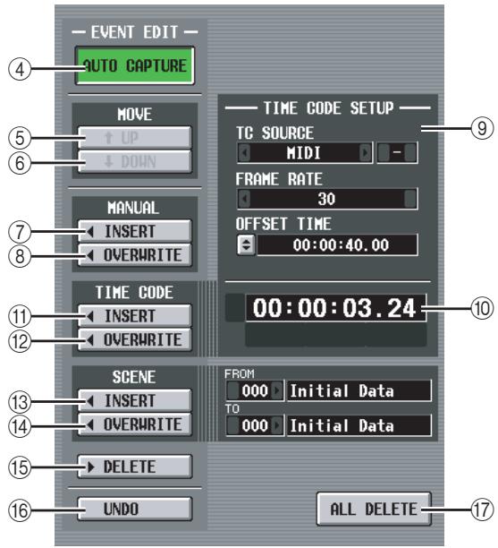
(4) AUTO CAPTURE
This button lets you automatically register events in realtime while time code runs. If time code is running and this button is on, using the buttons of the panel SCENE MEMORY to recall a scene will cause the corresponding scene number and time code location to be captured, and this will be added as a new event.
Note
- If the list contains previously-recorded events, they will be sorted in descending order of their time code.
- If an event already exists at the identical time code location, it will be overwritten by the new event.
- Even if time code source is "OFF," performing a recall operation while this button is on will register a new event in the list. In this case, the EVENT TRIGGER field will be registered as "[MANUAL]".
- If an offset value is specified, the sum of the offset value and the displayed time code is captured as the time code.
⑤ MOVE UP
This button moves the currently selected event one position earlier in the event list.
(6) MOVE DOWN
This button moves the currently selected event one position later in the event list.
Note
- The MOVE UP/DOWN buttons are available only for events whose EVENT TRIGGER field is shown as "[MANUAL]" or the "→" symbol.
- If the EVENT TRIGGER field of the selected event shows a time code, these buttons will be grayed-out and unavailable.
(7) MANUAL INSERT
This button inserts a new event at the location selected in the event list. The EVENT TRIGGER field of the new event will be “[MANUAL],” and its SCENE TITLE field will be “no assignment.” You can change these as desired.
(8) MANUAL OVERWRITE
This button overwrites a new event onto the location currently selected in the event list. (If the line at the current location is blank, this button will be grayed-out and unavailable.) The EVENT TRIGGER field of the new event will be "[MANUAL]."
⑨ TIME CODE SETUP
Here you can make settings for the time code received by the PM5D.
- TC SOURCE (Time code source)
Select one of the following as the time code source that will be used.
OFF . Time code will not be received.
INTERNAL .... The time code generated within the PM5D will be used.
TIME CODE . . . The time code (LTC) received via the rear panel TIME CODE connector will be used.
MIDI . The MIDI time code (MTC) received via the rear panel MIDI IN connector will be used.
USB . The MIDI time code received from the specified port via the rear panel USB connector will be used.
SLOT 1-4 .... If a card that supports MIDI input is installed in one of the rear panel slots, the MIDI time code received from the specified port will be used.
Note
- This setting does not affect the MIDI REMOTE function MIDI SETUP screen.
- If you select USB or SLOT 1-4, you will need to specify the port number (1-8) in the field on the right (Depending on the card that is installed, some slots may have only one port.)
- If you switch to INTERNAL, the time code will be set to the Start Time value.
- FRAME RATE
Select one of the following as the frame rate for the time code (LTC, MTC, internal time code) you are using.
30 30 frames/second (non-drop)
30D 30 frames/second (drop frame)
29.97 29.97 frames/second (non-drop)
29.97D . . . . 29.97 frames/second (drop frame)
25 25 frames/second
24 24 frames/second
- OFFSET TIME/START TIME
If INTERNAL is selected as the time code source, use this field to specify the time at which internal time code will begin (START TIME).
If any other time code source is selected, use this field to specify the offset (OFFSET TIME). The offset is the interval by which the timing at which scenes are recalled is adjusted backward or forward relative to the incoming time code (LTC or MTC).
In either case, you can edit the value by clicking the button and specifying the value in hours/minutes/seconds/frames units in the window that appears.
Time code display area
This displays the value of the incoming time code (LTC or MTC) or the internal time code. If INTERNAL is selected as the time code source, transport buttons are shown immediately below the time code value; you can use these buttons to rewind, stop, or start the internal time code.
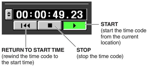
In addition, if INTERNAL is selected you can click the button to access the TIME CODE window, and specify the time code directly.
Note
An offset value is not added to the displayed time code.
⑪ TIME CODE INSERT
This button registers the time code data in the list in realtime. When the time code source is running, clicking this button will capture the time code value and add it as a new event. The captured time code is input in the EVENT TRIGGER field of the new event, and the SCENE TITLE field will be "no assignment." At this time, the events within the list are sorted in descending order of time code. (If an event exists at the same time location, it will be overwritten by the new event.)
Note
If the time code source is OFF, the EVENT TRIGGER column will be [MANUAL]. If the time code source is TIME CODE, MIDI, USB, or SLOT 1-4, the offset value has been added to the time code value of the newly added event.
⑫ TIME CODE OVERWRITE
This button replaces the time code of the event selected in the list in realtime. When the time code source is running, clicking this button will write the current time location as the time code value of the currently selected event. (The SCENE TITLE field will not change.) At this time, the events within the list are sorted in descending order of time code.
If a blank line is selected, this button is grayed-out.
Note
If the time code source is OFF, the EVENT TRIGGER column will be [MANUAL]. If the time code source is TIME CODE, MIDI, USB, or SLOT 1-4, the offset value has been added to the rewritten time code value.
13 SCENE INSERT
This button inserts one or more consecutive scenes from scene memory into the event list. Use the FROM/ TO fields located at right to specify the starting and ending scene numbers, and click this button; the specified scenes will be inserted as new events for recall immediately before the currently selected event. The EVENT TRIGGER field is set to "[MANUAL]" for all of the new events.
14 SCENE OVERWRITE
This button overwrites the scene assignments of consecutive events in the event list with multiple consecutive scenes from scene memory. Use the FROM/TO fields located at right to specify the starting and ending scene numbers, and click this button; starting at the currently selected line of the event list, the SCENE TITLE field of the corresponding number of subsequent events will be rewritten to the scenes you specified. (The EVENT TRIGGER field will not change.) If a blank line is selected, this button is grayed-out.
15 DELETE
This button deletes the event selected in the event list. If a blank line is selected, this button is grayed-out.
16 UNDO
This button returns the event list to its state prior to the most recent editing operation. If undo cannot be executed, this button is grayed-out.
17 ALL DELETE
This button deletes all events from the event list. When you click this button, a confirmation message will appear.
Note
If you edit the list (4-8,11-17) or change the time code, the NEXT EVENT button in the constantly-displayed area will search from the current time code. However if the time code source is OFF, or if there is no time code setting in the EVENT TRIGGER field (only for [MANUAL] and [INTERVAL]), the NEXT EVENT will be the beginning of the list.
SELECTIVE RECALL screen
In this screen you can make settings for the Selective Recall function, which, independently for each scene, lets you exclude specific parameters/channels from recall, or conversely recall only specific parameters/channels.
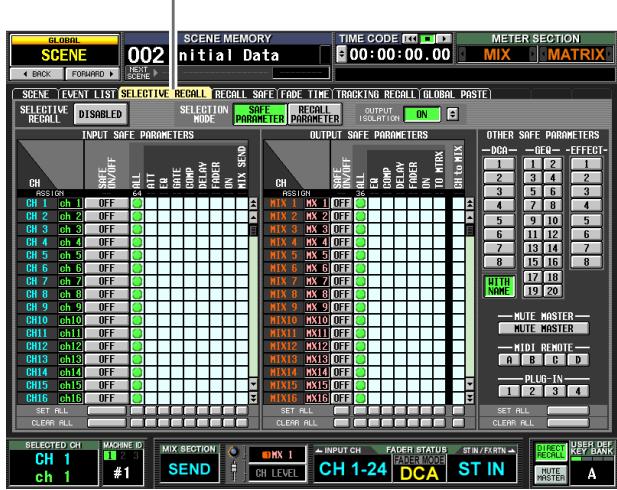
SELECTIVE RECALL
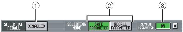
① SELECTIVE RECALL ENABLED/DISABLED
Enables/disables Selective Recall for the currently selected scene. If this button is set to DISABLED, the Selective Recall function is disabled.
Note
- Unlike the RECALL SAFE screen (→ p.182) which is common to all scenes, the settings in the SELECTIVE RECALL screen are independent for each scene.
- If you edit the settings of the SELECTIVE RECALL screen, you must store that scene in order to make your changes effective.
(2) SELECTION MODE
Use the following two buttons to choose how you want to use the SELECTIVE RECALL screen.
- SAFE PARAMETER button
If this button is on, you can specify the channels/ parameters that will be excluded from recall operations.
- RECALL PARAMETER button
If this button is on, you can specify the channels/ parameters that will be recalled. Immediately after you switch buttons, all channels/ parameters will be subject to recall.
③ OUTPUT ISOLATION
If the ON button is on, output channels and parameters to be excluded from recall operations can be memorized in SETUP memory (not included in memory card load operations) separately from the Recall Safe function. To specify the output channels and parameters that will be excluded from recall, make settings in the OUTPUT ISOLATION SETUP window that appears when you click the button.
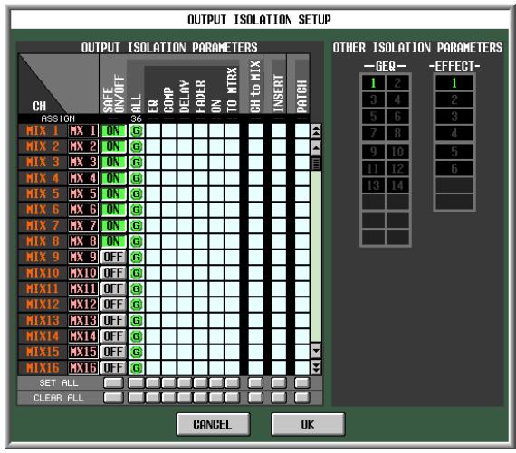
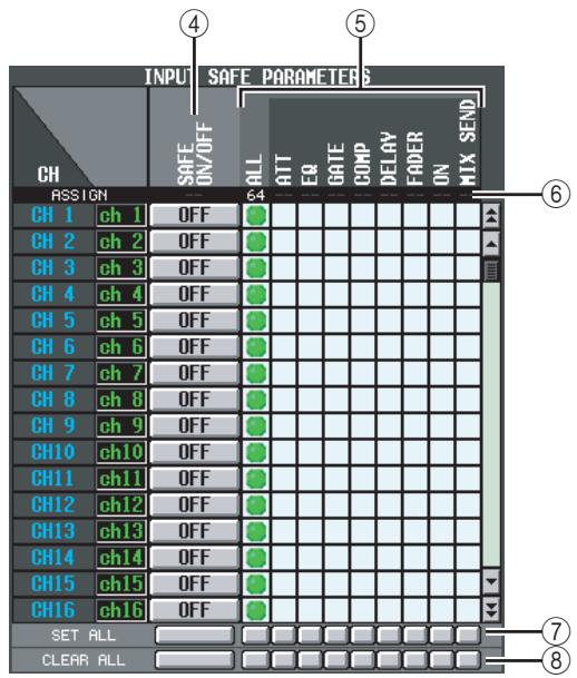
④ SAFE ON/OFF buttons RECALL ON/OFF buttons
The function of these buttons will depend on the SELECTION MODE (②) setting.
If the SAFE PARAMETER button is on
These buttons function as SAFE ON/OFF buttons that specify the channels excluded from recall operations.
If the RECALL PARAMETER button is on
These buttons function as RECALL ON/OFF buttons that specify the channels that will be recalled.
⑤ Parameter matrix grid
Here you can select the parameters that will be recalled (or excluded from recall). SAFE PARAMETER selections are shown in green, and RECALL PARAMETER selections are shown in blue. If the ALL button is on, all parameters other than CH to MIX will be recalled (or excluded from recall).
Note
- Matrix grids corresponding to combinations that cannot be selected are grayed-out.
- Settings in the parameter matrix grid are ignored for channels whose SAFE ON/OFF button or RECALL ON/OFF button is switched off.
⑥ ASSIGN
This area indicates the number of assigned channels for each parameter.
⑦ SET ALL
These buttons turn on the buttons of all channels or all buttons of the corresponding parameter.
(8) CLEAR ALL
These buttons turn off the buttons of all channels or all buttons of the corresponding parameter.
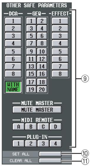
OTHER SAFE/RECALL PARAMETERS
By using these buttons, parameters other than those described above can be excluded from recall operations.
If the SAFE PARAMETER button is turned on in the SELECTION MODE (②) area, these buttons specify the parameters that will be excluded from recall. If the RECALL PARAMETER button is turned on, these buttons specify the parameters that will be recalled.
The DCA area contains a WITH NAME button. This lets you specify whether the DCA group name will be subject to recall operations.
10 SET ALL
This button turns on all buttons of the OTHER SAFE PARAMETERS area.
⑪ CLEAR ALL
This button turns off all buttons of the OTHER SAFE PARAMETERS area.
When using Selective Recall, parameters of which only one instance for every two adjacent odd-numbered/even-numbered channels/modules will be handled as follows if only one of the channels/modules is set to Selective Recall.
- PAIR
These parameters will not be recalled.
GATE STEREOLINK
COMPSTEREOLINK
- GEQ LINK
The LINK parameter will be forcibly turned off (linking will be disabled).
- DELAY GANG
ATT GANG
The GANG parameter will be recalled. If GANG is turned on because of the recall, operation will maintain the difference in the DELAY/ATT parameter values following the recall.
- MS DECODE
FIXED/VARI
These parameters will not be recalled.
PAN MODE
The PAN MODE parameter will be recalled. However if the PAN MODE would be changed by the recall from BALANCE to any other setting, or if it would be changed to BALANCE from any other setting, the PAN MODE and PAN parameters will not be recalled. If the recall causes PAN MODE to be set to GANG PAN, the difference in PAN parameter values will be maintained for operation following the recall.
Note
- Recall Safe and Selective Recall can be used together. Channels/parameters excluded from recall operations by either Recall Safe or Selective Recall (or both) will not be recalled.
- Selective Recall applies when a scene is recalled in PREVIEW mode.
- When you recall a scene, there may be cases in which a conflict in pairing settings between Recall Safe and Selective Recall causes the settings of a parameter to differ between L and R channels. In such cases, the parameter will be linked when it is next operated.
RECALL SAFE screen
Here you can specify parameters/channels that will be excluded from recall operations for all scenes.
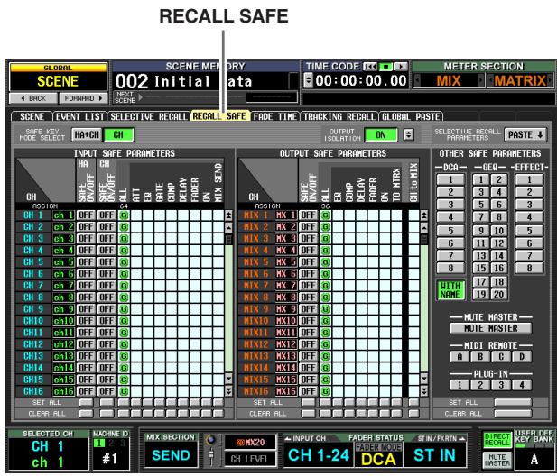
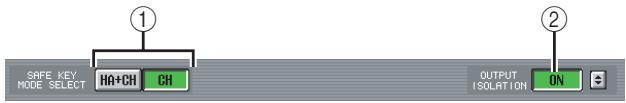
① SAFE KEY MODE SELECT (Safe Key Mode selection)
If the HA + CH button is on, Recall Safe will also turn on/off for the HA patched to the corresponding channel when you operate the panel [RECALL SAFE] key or the RECALL SAFE button (INPUT VIEW function CH VIEW screen) to turn Recall Safe on/off. If the CH button is on, this will not be linked.
(2) OUTPUT ISOLATION
If the ON button is on, output channels and parameters to be excluded from recall operations can be memorized in SETUP memory (not included in memory card load operations) separately from the Recall Safe function ( p.180).
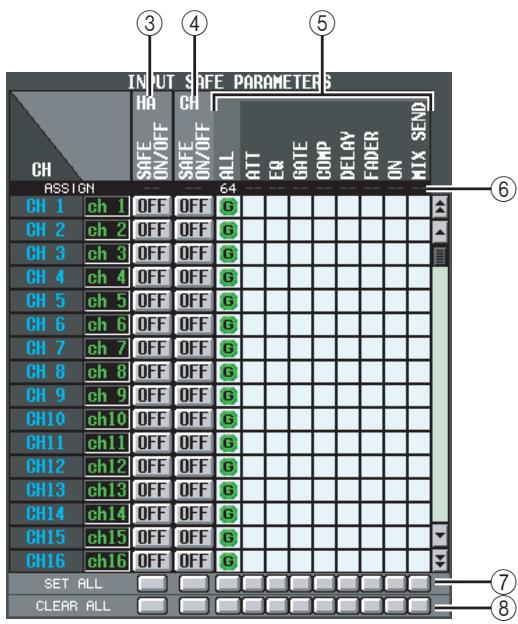
③ HA SAFE ON/OFF (Head Amp safe on/off) buttons
These buttons select the channels whose assigned HA (Head Amp) will be excluded from recall operations.
Note
If you scroll the scroll bar downward, you will see that the CH column of the SAFE PARAMETERS area shows not only input channels but also the following input ports. AD1-AD48 . . . INPUT jacks 1-48 AD1L-AD4R . . . L/R channels of ST IN jacks 1-4 ExHA1-1-ExHA8-8. . . . Channels 1-8 of external head amps 1-8 (AD8HR or AD824)
CH SAFE ON/OFF (Channel safe on/off) buttons
These buttons select the channels that will be excluded from recall operations. These are linked with the [RECALL SAFE] key of the panel.
⑤ Parameter matrix grid
Here you can select the channel parameters that will be excluded from recall operations. If the ALL button is on, all parameters except for CH to MIX will be excluded.
Recall Safe and Selective Recall can be used together. Channels/parameters excluded from recall operations by either Recall Safe or Selective Recall (or both) will not be recalled.
Note
Settings in the parameter matrix grid are ignored for channels whose CH SAFE ON/OFF button is OFF.
⑥ ASSIGN
This area indicates the number of assigned channels for each parameter.
⑦ SET ALL
These buttons turn on the buttons of all channels or all buttons of the corresponding parameter.
(8) CLEAR ALL
These buttons turn off the buttons of all channels or all buttons of the corresponding parameter.
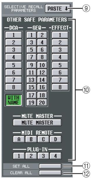
(9) SELECTIVE RECALL PARAMETERS PASTE
This button copies parameter settings from the SELECTIONIVE RECALL screen, and pastes them into the RECALL SAFE screen. When you click the button, a confirmation message will appear.
OTHER SAFE PARAMETERS
By using these buttons, parameters other than those described above can be excluded from recall operations.
The DCA area contains a WITH NAME button. If this button is on, Recall Safe will apply to the DCA group name of DCA groups that are on. If the WITH NAME button is off, the DCA group name is excluded from Recall Safe.
11 SET ALL
This button turns on all buttons of the OTHER SAFE PARAMETERS area.
⑫ CLEAR ALL
This button turns off all buttons of the OTHER SAFE PARAMETERS area.
When using Recall Safe, parameters of which only one instance for every two adjacent odd-numbered/even-numbered channels/modules will be handled as follows if only one of the channels/modules is set to Recall Safe.
- PAIR
The setting will be forcibly turned off (pairing will be disabled).
GATE STEREOLINK
COMPSTEREOLINK
- GEQ LINK
The LINK parameter will be forcibly turned off (linking will be disabled).
- DELAY GANG
ATT GANG
The GANG parameter will be recalled. If GANG is turned on because of the recall, operation will maintain the difference in the DELAY/ATT parameter values following the recall.
- MS DECODE
FIXED/VARI
These parameters will not be recalled.
PAN MODE
The PAN MODE parameter will be recalled. However if the PAN MODE would be changed by the recall from BALANCE to any other setting, or if it would be changed to BALANCE from any other setting, the PAN MODE and PAN parameters will not be recalled. If the recall causes PAN MODE to be set to GANG PAN, the difference in PAN parameter values will be maintained for operation following the recall.
Hint
- Selective Recall applies when a scene is recalled in PREVIEW mode.
- When you recall a scene, there may be cases in which a conflict in pairing settings between Recall Safe and Selective Recall causes the settings of a parameter to differ between L and R channels. In such cases, the parameter will be linked when it is next operated.
FADE TIME screen
Here you can specify how fader and pan will change smoothly to their new values over a specified duration when the scene is recalled.

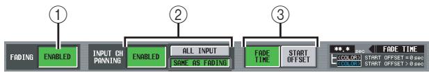
① FADING ENABLED/DISABLED
Enables/disables the Fade function for fader levels.
Note
- The settings in the FADE TIME screen are independent for each scene. If you edit these settings, you must store that scene in order to make your changes effective.
- The Fade function will apply when you recall a scene for which the ENABLED button is selected.
② INPUT CH PANNING ENABLED/DISABLED (Input channel panning enable/disable)
If the ENABLED button is selected, the Fade function will also apply to the PAN (BALANCE) parameter of input channels. This button is independent from the FADING ENABLED/DISABLED (①) setting. Use the following two buttons to select the input channels to which this will apply.
- When the ALL INPUT button is on
The Fade function will apply to the PAN (BALANCE) parameter of all input channels.
- When the SAME AS FADING button is on
The Fade function will apply to the PAN (BALANCE) parameter of only the input channels you select in ④.
③ FADE TIME/START OFFSET
Use the following two buttons to select the parameters that can be viewed/edited in the FADE TIME screen. The indication at the right shows which button is currently selected.
- When the FADE TIME button is on
Edit the time (fade time) over which the fader or pan parameter of the corresponding channel will reach the new value when you recall a scene for which the Fade function is enabled.
- When the START OFFSET button is on
Edit the time (start offset time) after which the fader or pan parameter of the corresponding channel will begin changing when you recall a scene for which the Fade function is enabled.
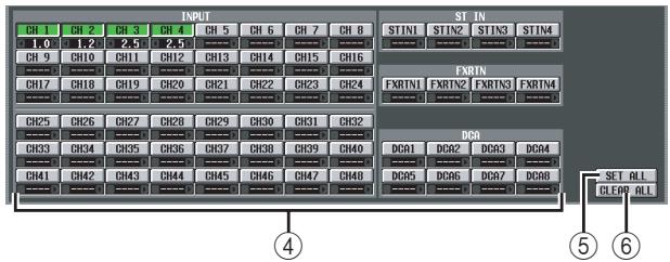
④ Channel settings
Here you can turn the Fade function on/off and specify the fade time (or the start offset time) for each input channel / output channel.
Use the channel name buttons to switch the Fade function on/off. The box below each button lets you specify the fade time or start offset time. Move the cursor to a box, and turn the [DATA] encoder or click the l / 串 buttons at the left and right to edit the value.
The color of the numerical value shown in the box will change as follows.
- When the FADE TIME button is on
The value is displayed in white for channels whose start offset time is "----" (unset), and in light blue for channels that are set to 0.1 or above.
- When the START OFFSET button is on
The value is displayed in red for channels whose start offset time is "----" (unset), and in yellow for channels that are set to 0.1 or above.
If desired, you can copy the fade time / offset time value from one channel to another as follows. Move the cursor to the box that displays the value you want to copy; then hold down the [SHIFT] key and press the [ENTER] key to access the JOB SELECT window.
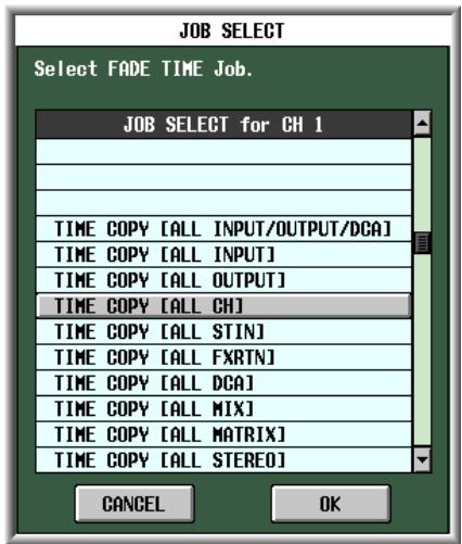
In this window, select the copy-destination item and click the OK button; the value of the selected channel will be copied.
⑤ SET ALL
This button enables the Fade function for all input channels or output channels.
(6) CLEAR ALL
This button disables the Fade function for all input channels or output channels.
TRACKING RECALL screen
Here you can make settings for the Tracking Recall function, which adds a specified offset value to the value of each fader when you recall a scene.
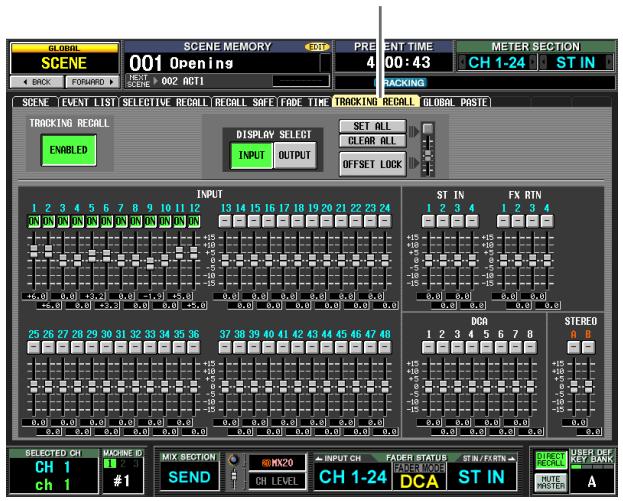
TRACKING RECALL
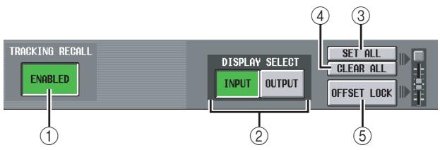
① TRACKING RECALL ENABLED/DISABLED
Enables/disables the Tracking Recall function.
Hint
The settings in the TRACKING RECALL screen apply to all scenes.
② DISPLAY SELECT
These buttons select the type of channels that are shown in the TRACKING RECALL screen; either INPUT (input channels) or OUTPUT (output channels).
③ SET ALL
This button enables Tracking Recall for all channels (including channels not currently shown in the screen).
(4) CLEAR ALL
This button disables Tracking Recall for all channels (including channels not currently shown in the screen).
⑤ OFFSET LOCK
If this button is on, the sliders of all channels (including channels not currently shown in the screen) will be grayed-out, and you will be unable to edit the offset value.
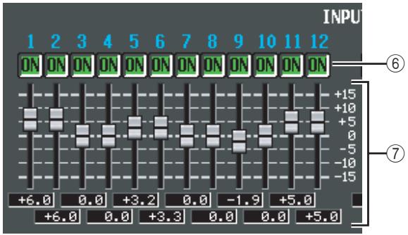
⑥ ON (Tracking On)
These buttons enable/disable tracking for each channel. If the TRACKING RECALL ENABLED/ DISABLED button is set to ENABLED, tracking is enabled on channels for which this button is ON.
Note
If OFFSET LOCK (⑤) is off, turning this button on will reset the tracking offset of the corresponding channel to 0 dB. If in this state you operate the fader of the corresponding channel, the relative amount of fader movement from the point at which this button was turned on will be memorized as the tracking offset. You can then turn OFFSET LOCK on to lock the offset. This offset value will be added whenever you subsequently recall a scene.
⑦ Tracking offset
Here you can specify the offset value applied to each channel if tracking is enabled. The range is ± 15 dB. While OFFSET LOCK (⑤) is off, operating the panel faders will cause these values to change as well; however, adjusting the offset values in the screen will not cause the panel faders to move.
GLOBAL PASTE screen
This screen lets you copy parameter settings of any desired channel or parameter in the current scene, and paste them into one or more scenes in scene memory.
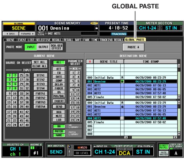

(1) PASTE MODE
Select the type of copy-source parameter from the following choices. You cannot select more than one type simultaneously.
INPUT .......Input channel parameters
OUTPUT....Output channel parameters
DCA, GEQ, EFFECT . . . DCA level or mute on/off status, GEQ settings, internal effect settings
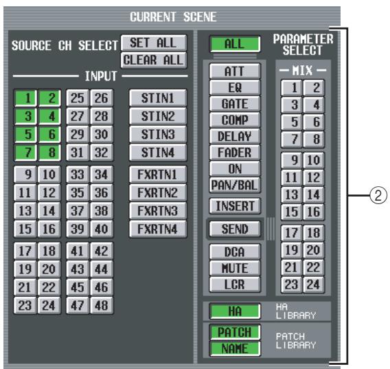
(2) CURRENT SCENE
Here you can select the channels and parameters that will be copied from the currently selected scene. The contents shown in this area will depend on the paste mode (①) you choose.
- If Paste Mode=INPUT
Select input channels in the left area, and select parameters in the right area. You can select the following parameters.
| ALL | All parameters except for HA, PATCH, and NAME |
| ATT | Attenuator |
| EQ | EQ function settings |
| GATE | GATE function settings |
| COMP | COMP function settings |
| DELAY | DELAY function settings |
| FADER | Fader level |
| ON | CH [ON] key on/off status |
| PAN/BAL | Pan/balance settings |
| INSERT | Insert on/off status and insert point |
| SEND*1 | Send level to the desired MIX bus(es) |
| DCA | Associated DCA group |
| MUTE | Associated mute group |
| LCR | LCR screen settings |
| HA | Settings for the head amp assigned to the corresponding input channel |
| PATCH | Settings for the input patch assigned to the corresponding input channel |
| NAME | Name assigned to the corresponding input channel |
*1. If the SEND button is on, use the MIX buttons (1-24) to select the applicable MIX bus. If the MIX bus is paired, SEND PAN is included in PAN/BAL if FOLLOW PAN "VARI" is on, or included in SEND if it is off.
- If Paste Mode= OUTPUT
Select output channels in the left area, and select parameters in the right area. You can select the following parameters.
| EQ | EQ function settings |
| COMP | COMP function settings |
| DELAY | DELAY function settings |
| FADER | Fader level |
| ON | CH [ON] key on/off status |
| BAL | Balance settings |
| INSERT | Insert on/off status and insert point |
| TO MTRX*1 | Send level to the desired MATRIX bus(es) |
| DCA | Associated DCA group |
| MUTE | Associated mute group |
| LCR | LCR screen settings |
| WITHOUT MIX SEND/ WITH MIX SEND | Selects whether the send level sent from input channels to the selected MIX bus will be included (WITH...) or will not be included (WITHOUT...) in the pasted data. |
*1. If the TO MTRX button is on, use the MATRIX buttons (1-8) to select the applicable MATRIX bus.
Note
- If Paste Mode= INPUT, and the parameter being pasted is NAME, the name library linked to the selected scene will be searched automatically and pasted.
- Be aware that if other scenes link to this library, the paste operation will overwrite the library, meaning that other scenes may be affected.
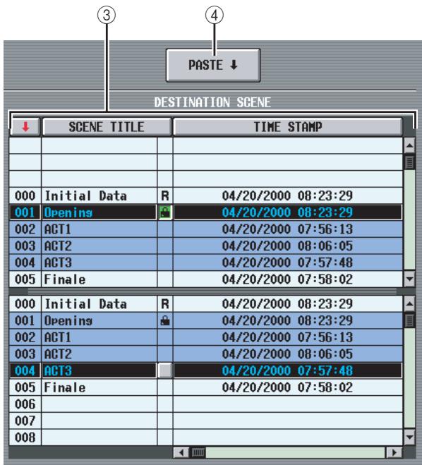
(3) DESTINATION SCENE (Paste-destination scene)
This list lets you select the scenes to which the data will be pasted. If you want to select multiple consecutive scenes as the paste-destination, select the starting number in the upper list and the ending number in the lower list. (If you're pasting to only one scene, select the same scene in the upper and lower lists.)
You can change the order in which the list is sorted by clicking the buttons shown at the top of the scene number, SCENE TITLE, TIME STAMP, or COM-MENT columns.
(4) PASTE
This button executes the Global Paste operation. When you click this button, a confirmation message will appear.
In the case of parameters such as those listed below, of which only one exists for each two adjacent odd-numbered/even-numbered channels or modules, the parameter will be pasted only if both channels/modules are specified for pasting.
GATE STEREOLINK
COMPSTEREOLINK
- DELAY GANG
PAN MODE
- GEQ LINK
ATT GANG
MS DECODE
FIXED/VARI
Note
- Paste is valid even in Preview mode.
- When you paste to a scene, there may be cases in which a conflict in pairing settings causes the settings of a parameter to differ between L and R channels. In such cases, the parameter will be recalled with those settings, and will be linked when it is next operated.
MIDI REMOTE function
Note
The various MIDI REMOTE function screens other than the DME CONTROL screen are invalid if the DSP5D is selected.
MIDI SETUP screen
Here you can select the types of MIDI message transmitted and received by the PM5D, and select the MIDI port that will be used.
MIDI SETUP
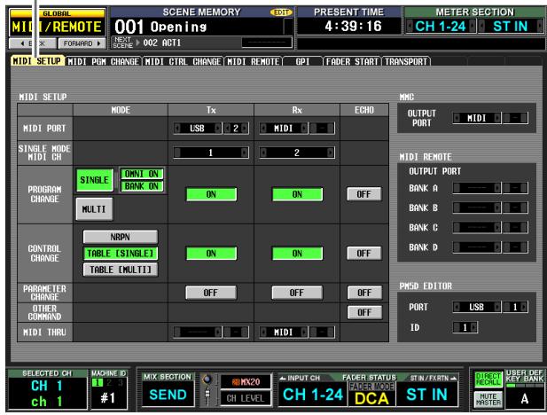
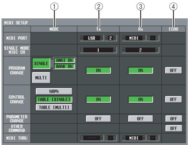
① MODE
Here you can select the way in which program changes and control changes will be transmitted/received.
PROGRAM CHANGE MODE
In this area you can select the program change transmission/reception method.
SINGLE
If this button is on, program changes will be transmitted/received on a single MIDI channel (Single mode).
OMNI ON/OFF
If this button is on, program changes of all MIDI channels will be received in Single mode (this is unavailable in Multi mode).
BANK ON/OFF
If this button is on, bank select messages will be transmitted and received in Single mode (this is unavailable in Multi mode).
MULTI
If this button is on, program changes will be transmitted/received on multiple MIDI channels (Multi mode).
Hint
- If program change reception is on, the PM5D's scenes or effects will switch when the appropriate program change is received from an external device. Additionally, if transmission is on, program changes will be transmitted to an external device when scenes or effects are switched on the PM5D.
- The scene/effect assignment for each program change number is made in the MIDI PGM CHANGE screen (p.190).
- CONTROL CHANGE MODE
In this area you can select the control change transmission/reception method.
NRPN
If this button is on, PM5D mix parameters will be transmitted/received as NRPN messages.
TABLE [SINGLE]
If this button is on, PM5D mix parameters will be transmitted/received as control change messages on a single MIDI channel.
TABLE [MULTI]
If this button is on, PM5D mix parameters will be transmitted/received as control change messages on multiple MIDI channels.
Hint
- If control change reception is on, the PM5D's parameters will change when the appropriate control change is received from an external device. If transmission is on, a control change will be transmitted to an external device when you edit a parameter on the PM5D.
- If NRPN is selected as the control change mode, the assignment of parameters to NRPN is pre-defined and cannot be changed.
- If TABLE [SINGLE] or TABLE [MULTI] is selected as the control change mode, the parameter assignment for each control number can be edited in the MIDI CTRL CHANGE screen (→ p.191).
② Tx (MIDI transmission)
Here you can make various settings for transmission of MIDI messages.
- MIDI PORT Tx (MIDI transmission port)
Select the port at which the PM5D will transmit MIDI messages. You have the following choices.
MIDI .The rear panel MIDI IN connector USB . The rear panel USB connector
SLOT 1-4 ...A card that supports serial transmission and is installed in rear panel slot 1-4
Move the cursor to this box and turn the [DATA] encoder or click the 4 / 5 buttons at left or right to change the setting; then press the [ENTER] key to finalize the change.
If you select USB or SLOT 1-4, you will need to specify the port number (1-8) in the field on the right (Depending on the card that is installed, some slots may have only one port.)
- SINGLE MODE MIDI CH Tx (MIDI transmission channel for Single mode)
Select the MIDI channel on which the PM5D will transmit program changes, control changes, parameter changes, and bulk data. (This setting is valid only in Single mode.) Move the cursor to this box and turn the [DATA] encoder or click the l / 门 buttons at left or right to change the setting; then press the [ENTER] key to finalize the change. - PROGRAM CHANGE Tx (Program change transmission)
- CONTROL CHANGE Tx (Control change transmission)
- PARAMETER CHANGE Tx (Parameter change transmission)
These buttons turn transmission on/off for program changes, control changes, and parameter changes respectively.
Hint
Parameter changes are a method by which PM5D parameters are transmitted in the form of system exclusive messages.
- MIDI THRU Tx (Thru output)
Select the port from which messages input to MIDI THRU Rx will be output. The selection method is the same as for MIDI_PORT Tx.
③ Rx (MIDI reception)
Here you can make various settings for reception of MIDI messages.
- MIDI PORT Rx (MIDI reception port)
Select the port from which the PM5D will receive MIDI messages. - SINGLE MODE MIDI CH Rx (MIDI reception channel for Single mode)
Select the MIDI channel on which the PM5D will receive program changes, control changes, parameter changes, and bulk data. (This setting is valid only in Single mode.) - PROGRAM CHANGE Rx (Program change reception)
- CONTROL CHANGE Rx (Control change reception)
- PARAMETER CHANGE Rx (Parameter change reception)
These buttons turn transmission on/off for program changes, control changes, and parameter changes respectively.
- MIDI THRU Rx (Thru input)
Here you can select the port that will "thru input" the received MIDI messages.
④ ECHO (MIDI message echo output)
Here you can select whether received program changes, control changes, parameter changes, and other MIDI messages will be echoed out from the MIDI transmission port.
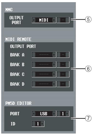
⑤ MMC OUTPUT PORT
This selects the port that will transmit MMC (MIDI Machine Control).
⑥ MIDI REMOTE OUTPUT PORT (MIDI remote output port)
Here you can select the port from which MIDI messages will be transmitted by the MIDI Remote function, for each of the four banks. Incoming messages used by the LEARN function of the MIDI REMOTE screen are also received at this port.
⑦ PM5D EDITOR (PM5D EDITOR connection port)
Here you can select the port and ID number (1-8) used to communicate with the PM5D Editor application, which controls the PM5D from a computer.
MIDI PGM CHANGE (MIDI program change) screen
In this screen you can select the scene or effect library assigned to each MIDI program number.
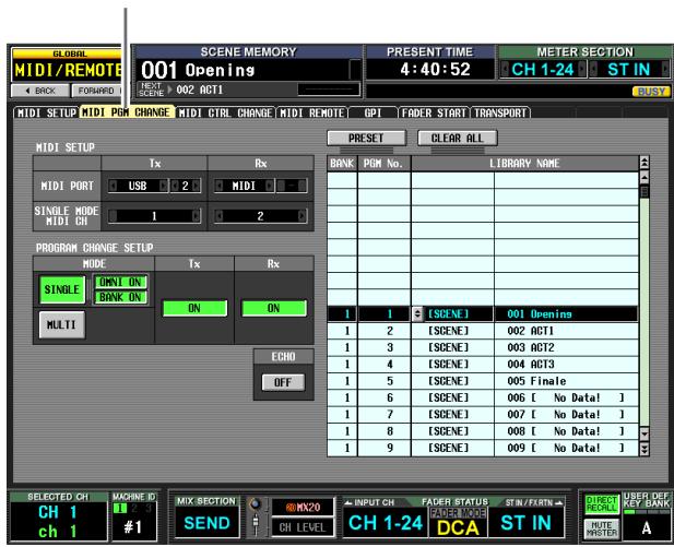
MIDI PGM CHANGE
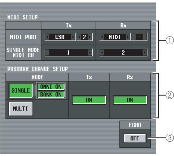
① MIDI SETUP
Select the ports that the PM5D will use to transmit and receive MIDI messages, and the MIDI channels. This item is linked with the settings in the MIDI SETUP screen.
② PROGRAM CHANGE SETUP
Here you can specify how program changes will be transmitted and received, and turn transmission and reception on/off. This item is linked with the settings in the MIDI SETUP screen.
③ ECHO ON/OFF
This selects whether program changes received from an external device are echoed-out from the MIDI transmission port. This item is linked with the settings in the MIDI SETUP screen.
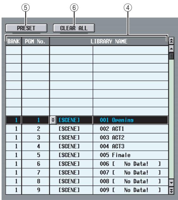
④ List
In this list you can view and select the event (scene recall / effect library recall) assigned to each program number.
- CH/BANK (Channel/Bank)
Indicates the MIDI channel on which the program change is transmitted/received. In Single mode when the BANK ON/OFF button is on, this column is displayed as BANK, and the value shown corresponds to the bank number.
- PGM No. (Program number)
Indicates the program number 1-128.
- LIBRARY NAME
Here you can view/select the type and the number of the event (scene or effect) assigned to each channel/ program number.
To make an assignment, click the desired line to select it. (That line will be highlighted in the center of the list.) Click the button shown at the left of the LIBRARY NAME field; the MIDI PGM CHANGE SETUP window will appear. In this window you can select the type of event (a scene, or a library item for effect 1-8) and its number.
When a program change on the corresponding MIDI channel is received, the event assigned to that program number will be recalled. In addition, the corresponding program change will be transmitted when this event is recalled on the PM5D.
(5) PRESET
Clicking this button will restore all event assignments in the list to their default state.
(6) CLEAR ALL
Clicking this button will delete all event assignments in the list.
MIDI CTRL CHANGE (MIDI control change) screen
Here you can select the PM5D parameter (fader operation, [ON] key operation, etc.) assigned to each control number.
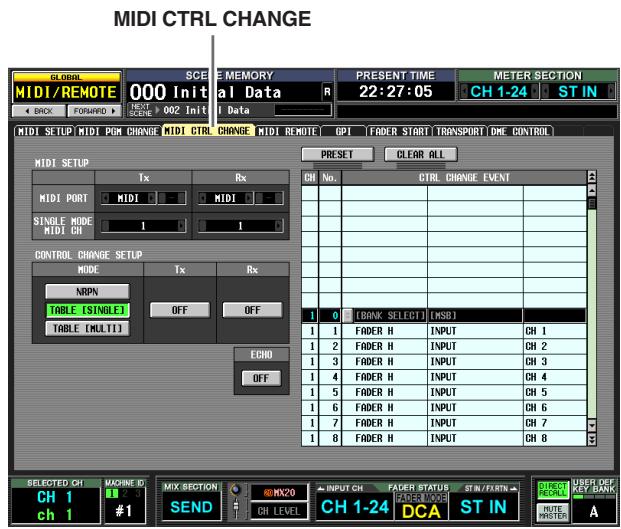
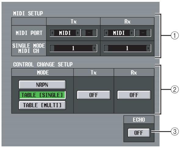
① MIDI SETUP
Select the ports that the PM5D will use to transmit and receive MIDI messages, and the MIDI channels. This item is linked with the settings in the MIDI SETUP screen.
(2) CONTROL CHANGE SETUP
Here you can specify how control changes will be transmitted and received, and turn transmission and reception on/off. This item is linked with the settings in the MIDI SETUP screen. You have the following choices of transmission/reception method.
NRPN
If this button is on, PM5D mix parameters will be transmitted/received as NRPN messages.
TABLE [SINGLE]
If this button is on, PM5D mix parameters will be transmitted/received as control change messages on a single MIDI channel according to the assignments in the list (④).
TABLE [MULTI]
If this button is on, PM5D mix parameters will be transmitted/received as control change messages on
multiple MIDI channels according to the assignments in the list (④).
③ ECHO ON/OFF
This selects whether control changes received from an external device are echoed-out from the MIDI transmission port. This item is linked with the settings in the MIDI SETUP screen.
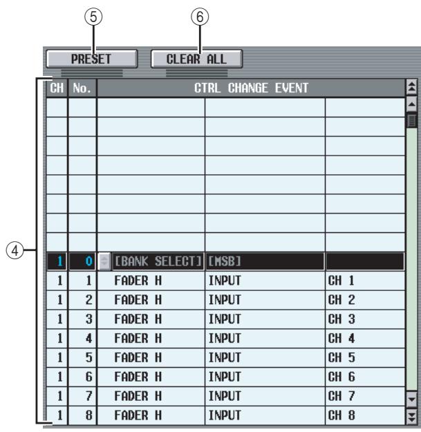
④ List
In this list you can view/select the events assigned to each control number.
- CH (Channel)
Indicates the MIDI channel on which the control change is transmitted/received.
- CTRL No. (Control number)
Indicates the control number 0-119. Control numbers 0, 32, and 96-110 cannot be specified.
- CTRL CHANGE EVENT (Control change event)
Indicates/selects the type of event assigned to the corresponding channel / control number.
To make an assignment, click the desired line (that line will be highlighted in the center of the list); then click the button at the left of the CTRL CHANGE EVENT field to open the MIDI CTRL CHANGE SETUP window. In this window you can specify the parameter in three levels (mode, parameters 1/2). When a control change on the corresponding MIDI channel is received, the event assigned to that control number will be edited. In addition, the corresponding control change will be transmitted when this event is edited on the PM5D.
Note
This list is ignored if the control change mode is set to NRPN.
(5) PRESET
Clicking this button will restore all event assignments in the list to their default state.
(6) CLEAR ALL
Clicking this button will delete all event assignments in the list.
MIDI REMOTE screen
Here you can assign MIDI messages to panel faders, CH [ON] keys, encoders, and ENCODER [ON] keys, and make settings for the MIDI Remote function used to control external devices.
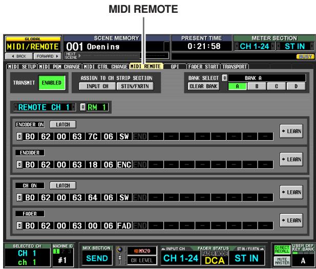
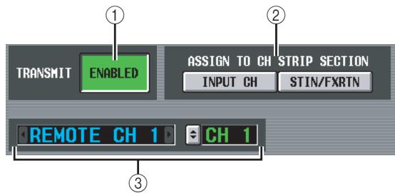
① TRANSMIT ENABLED/DISABLED (Enable/ disable transmission)
Enables/disables the MIDI Remote function. You can enable/disable this function for each of the four banks (memories in which MIDI Remote settings are stored).
② ASSIGN TO CH STRIP SECTION (Assign to channel strip)
You can choose the following two as the channel strip to which the MIDI Remote function is assigned (both can be selected simultaneously if desired).
INPUT CH ....... INPUT channel strip 1-24
STIN/FXRTN . . . . ST IN/FX RTN channel strip 1-4
This setting applies to all four banks.
③ Channel selection
Select the MIDI Remote channel for which you want to make settings. When you click the l buttons at the left and right of the box, the corresponding name is displayed in the box at the right. You can change the name by clicking the l button of the right box.
Note
You cannot change the MIDI Remote channel you're editing while any of the LEARN buttons (⑦) are on. You will have to turn off the LEARN button first.
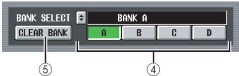
(4) BANK SELECT
Of the four banks, select the bank for which you want to make settings. When you use the A-D buttons to select a bank, the name of that bank will be displayed in the field immediately above. You can click the button at the left to edit the name of the bank.
⑤ CLEAR BANK
This button erases the currently selected bank (all MIDI messages will be deleted).
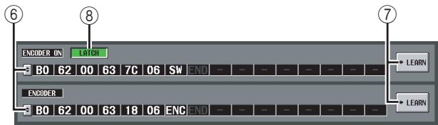
⑥ MIDI message
From the top, these fields assign MIDI messages to the ENCODER [ON] keys, encoders, CH [ON] keys, and faders. Click the 念 to open the MIDI REMOTE SETUP window, and input the message as hexadecimal values. You can input the following values.
| Value | Available Assignments | Content |
| 00(H)-FF(H) | All | The MIDI message that is trans-mitted (hexadecimal). |
| END | All | Indicates the end of the MIDI message. When you operate the corresponding controller, the MIDI message from the begin-ning until immediately before END will be transmitted. |
| SW | All | Indicates the on/off status of the encoder [ON] key or the channel [ON] key. A value of 7F(H) is transmitted when the key turns on, and a value of 00(H) is trans-mitted when the key turns off. If this is assigned to an ENCODER or FADER, the current value of the key will be transmitted when the encoder or fader is operated. |
| ENC | ENCODER ON/ENCODER | Indicates the current position of the encoder. If assigned to an ENCODER, a value of 00-7F(H) is transmitted when the encoder is operated. If assigned to an ENCODER [ON] key, the current value of the encoder is transmit-ted when the key is switched on. |
| FAD | CH ON/FADER | Indicates the current position of the fader. If assigned to a FADER, a value of 00-7F(H) is transmitted when the fader is operated. If assigned to a CH [ON] key, the current value of the fader is transmitted when the key is switched on. |
Hint
When you click a hexadecimal value, the region interpreted as a MIDI message that includes that value will be displayed in red.
⑦ LEARN
Use this button to assign a received MIDI message to a controller. When you turn on one of the four LEARN buttons, the MIDI message received by the PM5D will be assigned to the corresponding controller. The LEARN function uses the MIDI messages received at the input port specified by the MIDI REMOTE OUTPUT PORT in the MIDI SETUP screen.
Hint
- MIDI messages assigned using the LEARN button can be a maximum of 16 bytes long (the 17th and subsequent bytes are discarded). If the message is less than 16 bytes long, END will be immediately after the last data value.
- If a control change is received, the third byte will automatically be replaced by FAD (if the assignment destination is FADER), ENC (if the assignment destination is ENCODER), or SW (if the assignment destination is ENCODER ON or CH ON).
- If more than one message is received while a LEARN button is on, the last message will be used. (If the status byte was omitted from the last message, the appropriate status byte will be added.)
(8) LATCH
If a specific byte is set to "SW" in a message assigned to an ENCODER [ON] key or CH [ON] key, use the LATCH button to select one of the following behaviors.
- If the LATCH button is on
The on/off status will change each time you press the key (Latched). If you press the key from the Off state, a MIDI message with 7F(H) as the SW value will be transmitted, and when you press the same key once again a MIDI message with 00(H) as the SW value will be transmitted.
- If the LATCH button is off
The switch will be on only while you are holding it down, and will turn off when you release it (Unlatched). Immediately after you press the key, a MIDI message with 7F(H) as the SW value will be transmitted; immediately after you release the key, a MIDI message with a SW value of 00(H) will be transmitted.
If a specific byte is set to "ENC" (or "FAD") in a message assigned to an ENCODER [ON] key or a CH [ON] key, use the LATCH button to select one of the following behaviors.
- If the LATCH button is on
If you press the key from the Off state, a MIDI message with the current setting of the encoder (or fader) as the ENC (or FAD) value will be transmitted, and when you press the same key once again a MIDI message with a value of 00(H) as the ENC (or FAD) value will be transmitted.
- If the LATCH button is off
The moment you press the key, a MIDI message with the current setting of the encoder (or fader) as the ENC (or FAD) value will be transmitted; the moment you release the key, a MIDI message with 00(H) as the ENC (or FAD) value will be transmitted.
Note
If SW/ENC/FAD is not specified as the last byte of the MIDI message, turning the key on or off will transmit the same MIDI message; i.e., the same message is transmitted when the key goes off.
GPI screen
Here you can make settings for GPI (General Purpose Interface) input/output, used to transfer control signals between the PM5D and an external device.
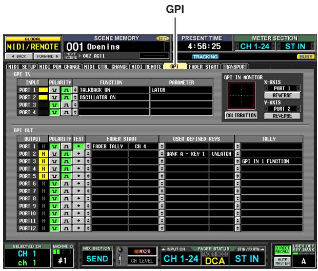
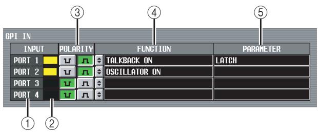
① GPI IN port
These are the numbers of the GPI IN ports for which you can make settings.
② GPI IN status
The yellow bar indicates the input signal voltage state of the corresponding port. If the bar is not shown, the signal is in the grounded state; if the bar is displayed to the right edge, the signal is at the high level state. Use the POLARITY (③) field to select whether the signal is active when low or high.
③ POLARITY
This selects how GPI IN on/off will be detected. You can choose Low Active (active when the key is grounded) or High Active (active when key is open, or when a high level signal is input).
(4) FUNCTION
(5) PARAMETER
These fields indicate the function that is executed when the corresponding GPI IN port becomes active (or the function that is controlled by the voltage value being input from the GPI IN port), and option parameters for that function.
To edit the settings, click the button at the left to open the GPI IN PORT ASSIGN window, and select the function and parameter from the following table.
| FUNCTION | PARAMETER | PM5D operation |
| NO ASSIGN | — | No assignment |
| MONITOR | DIMMER ON | Switches the Dimmer function on/off |
| SOURCE=[monitor source name] | Switches the monitor source | |
| MONO ON | Switches the monitor section [MONO] key on | |
| TALKBACK ON | LATCH | Switches the Talkback function on/off (latched operation) |
| UNLATCH | Switches the Talkback function on/off (unlatched operation) | |
| CH ON-LATCH | [channel name] | Switches the channel on/off (latched operation) |
| CH ON-UNLATCH | [channel name] | Switches the channel on/off (unlatched operation) |
| FADER LEVEL | [channel name] | Modifies the fader value (LEVEL parameter) according to the voltage |
| SUR-ROUND PAN | FRONT-REAR PAN [SEL] | according to the voltage. |
| LEFT-RIGHT PAN [SEL] | Modifies the surround pan-ning (left/right) of the selected channel accord-ing to the voltage. | |
| FRONT-REAR PAN [ODD] | Modifies the surround pan-ning (front/rear) of the selected odd-numbered channel according to the voltage. | |
| LEFT-RIGHT PAN [ODD] | Modifies the surround pan-ning (left/right) of the selected odd-numbered channel according to the voltage. | |
| FRONT-REAR PAN [EVEN] | Modifies the surround pan-ning (front/rear) of the selected even-numbered channel according to the voltage. | |
| LEFT-RIGHT PAN [EVEN] | Modifies the surround pan-ning (left/right) of the selected even-numbered channel according to the voltage. | |
| USER DEFINED KEY FUNC-TION | [User Defined key bank / key number] | While the external input is active, executes the same operation as when the selected User Defined key is pressed |
| USER DEFINED KEY LED | [User Defined key bank / key number] | While the external input is active, lights the LED of the selected User Defined key |
| PEAK HOLD ON | — | Switches the Peak Hold function on/off |
| OSCILLA- TOR ON | Switches the Oscillator on/off | |
| SOLO ON | Switches the Solo func-tion on/off |
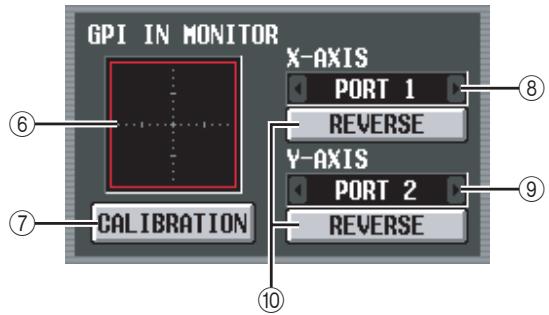
⑥ GPI IN monitor
The voltage from the GPI IN port selected by the X-AXIS field (⑧) and Y-AXIS field (⑨) is respectively indicated by a yellow in the X-axis (horizontal) and Y-axis (vertical) dimensions of the graph.
The range of voltage variation used to determine the active/inactive status is shown as a red rectangle.
⑦ CALIBRATION
This button calibrates the range of voltage variation used by the PM5D to determine active/inactive status, so that the range will be appropriate for the voltages being input from the GPI PORT. (For details on using calibration p.135)
When you turn this button on, the range of voltage variation will be temporarily cleared; the range will be updated every time the GPI IN voltage changes. When you turn this button off, the range of variation will be memorized, and this range of variation will subsequently be used to determine the active/inactive state.
(8) X-AXIS
⑨ Y-AXIS
These fields select the GPI IN port for which calibration will be performed. You can click the / buttons at left and right to change the port.
If you are using a two-dimensional controller such as a joystick, specify a port for both the X-axis and Y-axis. If you want to perform calibration for only one direction, set one of the ports to "----".
⑩ REVERSE
This button inverts the low/high level of the input, changing the displayed direction of the graph. This is equivalent to switching the POLARITY (③) of the selected GPI IN port.
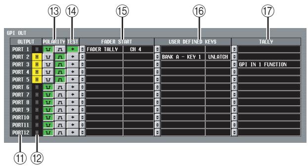
⑪ GPI OUT port
These are the numbers of the GPI OUT ports for which you can make settings.
⑫ GPI OUT status
This indicates the state of the output signal for the corresponding port. The L/H character indicates whether the signal level is Low (the output level is grounded) or High (the output level is high). The background color is yellow when active, and gray when inactive. Use the POLARITY (⑬) field to select whether the signal is active when low or high.
13 POLARITY
Selects the polarity of the signal that is output when the GPI OUT port becomes active. You can select either Low Active (grounded when active) or High Active (high level when active).
TEST
This button tests the operation of each GPI OUT port. While this button is on, the corresponding GPI OUT port will temporarily become active, and a signal will be output according to the POLARITY (13) setting.
15 FADER START
Indicates the channel of the fader assigned as a trigger to each GPI OUT port, and the fader mode (trigger detection method) of that fader.
To edit the settings, click the button at the left to open the GPI OUT PORT ASSIGN window, and select the fader mode and channel. You can select the following fader modes.
- FADER START
A control signal (trigger signal) 250 msec long will be output when the fader of the selected channel moves from -60 dB or below to exceed -60 dB.
- FADER STOP
A control signal (trigger signal) 250 msec long will be output when the fader of the selected channel reaches - dB.
- FADER TALLY
A control signal will be output when the fader of the selected channel moves from -60 dB or below to exceed -60 dB. This control signal will be held until the fader reaches - dB (or until that GPI OUT port receives a different trigger).
The setting of the GPI screen's FADER START field is linked with the GPI-related settings of the FADER START screen ( p.196).
16 USER DEFINED KEYS
This area indicates the User Defined keys that are assigned as triggers to each GPI OUT port, and their operations.
To edit the setting, click the button at the left to open the GPI OUT PORT ASSIGN window; from the list, select the User Defined key bank (A-D) and number (1-25), and how the trigger signal will be transmitted. As the transmission method for the trigger signal, you can select either Latch (switch between active/inactive each time the key is pressed) or Unlatch (active only while the key is pressed).
TALLY
This area indicates the state of other Tally output functions assigned as triggers to each port. When you execute the corresponding operation on the PM5D, a control signal will be output from the corresponding GPI OUT port. This control signal will be held until you defeat the above operation (or until that GPI OUT port receives a different trigger).
To edit the settings, click the button at the left to open the GPI OUT PORT ASSIGN window, and select one of the following functions.
| Function | PM5D operation |
| NO ASSIGN | No assignment |
| POWER ON | The PM5D's power is turned on |
| SOLO ON | [SOLO] key is turned on |
| GPI IN 1 FUNC-TION | The function assigned to GPI IN port 1 becomes active |
| GPI IN 2 FUNC-TION | The function assigned to GPI IN port 2 becomes active |
| GPI IN 3 FUNC-TION | The function assigned to GPI IN port 3 becomes active |
| GPI IN 4 FUNC-TION | The function assigned to GPI IN port 4 becomes active |
| PREVIEW ON | SCENE MEMORY section [PREVIEW] key is turned on |
| CUE ON [INPUT ONLY] | Input channel [CUE] key is turned on |
| CUE ON [DCA ONLY] | DCA [CUE] key is turned on |
| CUE ON [OUT-PUT ONLY] | Output channel [CUE] key is turned on |
| CUE ON | Any [CUE] key is turned on |
FADER START screen
Here you can make settings for the Fader Start function which lets you use input channel faders to control GPI OUT ports or external devices.
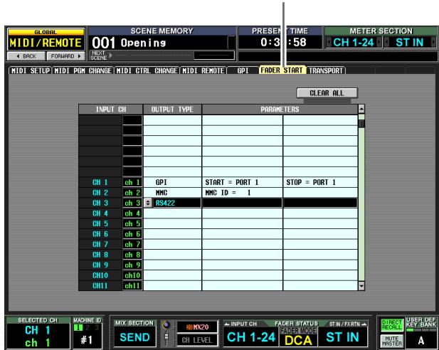
FADER START
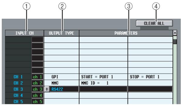
① INPUT CH (Input channel)
This area shows the number and name of the channels (input channels, ST IN channels) for which you can make settings. When you click a line to select it, that line will be highlighted in the center of the list.
② OUTPUT TYPE
(3) PARAMETER
Indicates the type of signal that will be output when you operate the corresponding fader, and option parameters for it. To edit the setting, click the button at the left of the OUTPUT TYPE field to open the FADER START ASSIGN window. You can select the following output types and parameters.
- NO ASSIGN
No assignment.
GPI
A trigger will be sent to the specified GPI OUT port according to the fader operation of the corresponding channel, and a control signal will be output. (The polarity of the control signal will be as specified by the settings in the GPI screen.) If this output type is selected, you can choose from the following two option parameters.
FADER START . . . GPI OUT port from which the trigger is sent when the fader changes from below -60 dB to exceed -60 dB.
FADER STOP . . . . GPI OUT port from which the trigger is sent when the fader reaches - dB.
Note that the GPI-related settings you make in the FADER START screen are linked with the FADER START field of the GPI screen.
For example, if in the FADER START screen you specify different ports for the FADER START parameter and FADER STOP parameter of a certain channel, the FADER START field of the GPI screen will be assigned to the corresponding channel (Fader Mode= FADER START/FADER STOP) of those ports. (The opposite also applies.)
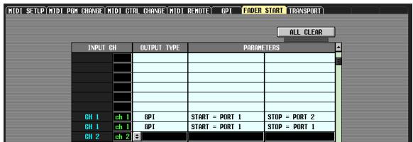
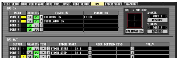
If the same port is specified for the FADER START parameter and the FADER STOP parameter, the GPI screen FADER START field will be assigned to the channel corresponding to that port (Fader Mode= FADER TALLY). (The opposite is also true.)
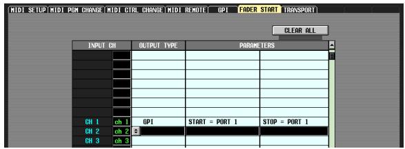
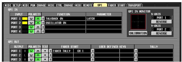
- MMC
An MMC command will be sent from the currently-enabled MIDI port according to the fader operation of the corresponding channel. (The MIDI transmit port is selected in the MIDI SETUP screen.)
An MMC PLAY command is transmitted when the fader changes from below -60dB to -60dB or higher, and an MMC STOP command is transmitted when the fader reaches - dB.
If this output type is selected, you can use an option parameter to specify the MMC device ID number (1- 127 or ALL).
RS422
An RS422 protocol command will be sent from the RS422 REMOTE connector according to the fader operation of the corresponding channel.
An RS422 protocol PLAY command is transmitted when the fader changes from below -60dB to -60dB or higher, and an RS422 protocol STOP command is transmitted when the fader reaches - dB.
(4) CLEAR ALL
Cleared the Output Type field assignments of all channels.
TRANSPORT screen
Here you can use MMC/RS422 protocol commands to remotely control transport/locate operations on a recorder or other external device from the PM5D.
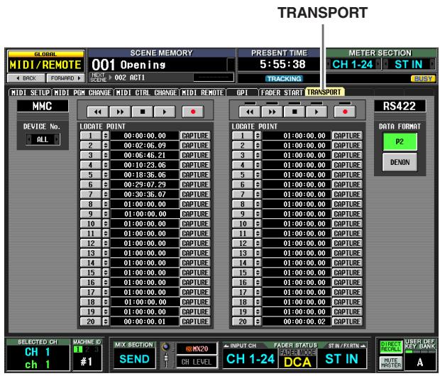
① MMC DEVICE No.
Indicates the device ID number of the external device to be controlled via MMC. To change this setting, click the / button at left and right to choose from the range 1-127 or ALL (applies to all device ID numbers).
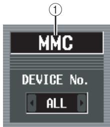
② RS422 DATA FORMAT
Select the format (P2 or DENON) of the RS422 commands sent from the RS422 REMOTE connector. When you click this button, a confirmation message will appear.
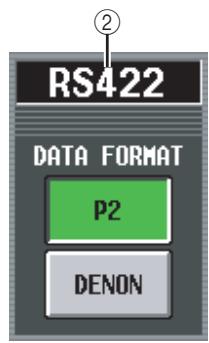
Note
The RS422 command format you specify in this screen also applies to the RS422 commands issued by the Fader Start function or the User Defined keys.
Note
DENON format is a set of commands used in devices such as Denon's professional CD (DN-C680) and MD (DN-M1050R) players. On the CD or MD player, set the settings to 9600 bps and RS422. If you are using DENON format, clicking the button during Play will enter Pause mode; clicking the button during Standby will Stop. While stopped, click the button once again if you want to Standby. Clicking the button will return to the previous track, and clicking the button will advance to the next track. Use a D-Sub 9-pin straight cable to connect the REMOTE RS422 connector to the device you wish to control using P2 or DENON format.
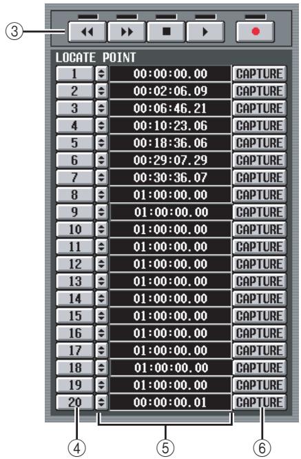
③ Transport
These buttons operate the transport of an external device. When you click a button, the corresponding MMC/RS422 command (from the left, REWIND, FAST FORWARD, STOP, PLAY, REC) will be transmitted.
There is an indicator above each RS422 transport button; the indicator will light as follows according to the status of the external device being controlled.
P2
| Playing | lit |
| Fast-forwarding | lit |
| Rewinding | lit |
| Stopped | lit |
| Recording | and lit |
DENON
| Playing | ● lit |
| Paused | ● blinking |
| Standby | ● lit |
| Stopped | All dark |
| Recording | ● and ● lit |
| Recording paused | ● lit, ● blinking |
(4) LOCATE POINT
These buttons correspond to each locate point. Twenty locate points can be specified for MMC-compatible devices, and another twenty locate points can be separately specified for RS422-compatible devices. When you click buttons 1-20, an MMC command or RS422 command for moving to that locate point will be transmitted.
⑤ Time code
This field indicates the time code that is specified for each locate point. To edit the time code, click the button located at the left to open the MMC/RS422 LOCATE POINT window, and specify the new time code in hours/minutes/seconds/frames. (In the case of DENON format, use track/minute/second/frame units to specify the value.) You can also use the CAPTURE button located at the right to capture the time code being received by the PM5D.
(6) CAPTURE
This button captures the time code currently being received by the PM5D, and inputs it in the time code field. In the case of MMC, the time code source, frame rate, and offset time can be specified in the EVENT LIST screen (SCENE function). ( p.177) In the case of RS422, the time data at that moment for the external device being controlled will be captured.
DME CONTROL screen
Here you can remotely control various functions of a Yamaha DME series digital mixing engine.
Hint
As of this writing (April 2007), this function can be used with the DME series models DME64N, DME24N, DME8i-C, DME8o-C, DME4io-C, DME8i-ES, DME8o-ES and DME4io-ES. (This function cannot be used with the DME32.)
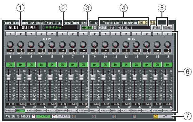
① Component type selection area
Here you can select the type of DME series component that you want to control from the PM5D. When you click the / buttons at the left and right to select the type of component, the display in the central area of the screen will change accordingly. The following types of component can be selected.
- SETUP
Select the port connecting the PM5D and the DME series unit, and initiate or terminate communication.
- GEQ
Control the DME series unit's graphic EQ from the PM5D.
PEQ
Control the DME series unit's parametric EQ from the PM5D.
CROSSOVER
An internal signal within the DME series unit is divided into six bands, and the output level, filter slope and type, and cutoff frequency etc. can be controlled for each band. This screen also lets you specify the crossover frequency at which the bands are divided.
- LONG DELAY
SHORT DELAY
Control the long delay and short delay functions of the DME series unit from the PM5D.
- MATRIX
Specify the level of the signals sent from a specific input of the DME series unit to all outputs, or from all inputs to a specific output.
- SLOT OUTPUT
For each slot of the DME series unit, specify the output level, delay time, and phase setting of each port.
② Component selection area
From the type of component you selected in ①, select the component that you want to control.
③ MONITOR
When you click the monitor source select button (@), the MONITOR POINT SELECT window will appear, allowing you to select the monitor source for the DME series. When you turn the MONITOR button on, the EXTERNAL CUE indicator in the upper part of the display will turn on, and the monitor signal of the DME series will be sent to the PM5D's CUE bus.
Note
If you want to turn the MONITOR button on, you must first select the same port for the DME series' monitor output and the PM5D monitor input. The monitor output of the DME series unit can be specified in the "Monitor Out" dialog box accessed from DME Designer via the [Tools] menu [Monitor]. The monitor input of the PM5D unit is specified by MONITOR PORT in the SETUP area of the DME CONTROL screen.
(4) SCENE
This area indicates/selects the scene that will be stored/ recalled on the DME series unit. When you click the / buttons located at left and right to select a number, the name of that scene is shown in the field at right.
(5) STORE/RECALL
These buttons save (overwrite) the settings of the DME series unit edited in the PM5D's screen into the scene selected in the SCENE area, or recall the scene selected in the SCENE area into the DME.
Note
- When storing a DME scene from the PM5D's screen, you can only store by overwriting an existing scene on the DME; you cannot store the settings as a new scene or edit the scene name.
- If SETUP is selected, items ③, ④, and ⑥ are not shown.
(6) Parameter display area
This area displays the parameters of the currently selected component. The displayed contents will depend on the component.
⑦ ASSIGN TO FADERS (DCA fader assignments)
You can use DCA faders 1-8 to control the parameters of the component currently shown in the screen.
Note
The parameters that can be assigned to DCA faders will depend on the component. This function may not be available for some components.
- Connecting the PM5D with a DME series unit
Various methods for connecting the PM5D with a DME series unit to transmit and receive audio signals and control signals are shown below.
Note
If characters other than alphabetical characters and symbols (e.g., double-byte characters such as Japanese) are used on the DME series unit in a component name or scene name, such characters may not be displayed correctly.
Bi-directional connection via CobraNet
This connection method uses CobraNet (a format for transmitting multi-channel audio signals and control signals over Ethernet). Install a MY-16CII CobraNet card in the PM5D's slot, and use an Ethernet cable to connect it to the DME series. This method allows bi-directional transfer of audio signals over a single cable. For example, signals can be sent via the PM5D's MIX bus to the DME for processing, and then returned to a PM5D input channel.
Note
You cannot use AuviTran's AVY16-ES EtherSound card to control the DME series from the PM5D.
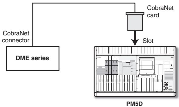
Bi-directional connection using the CASCADE IN/OUT connectors (DME64N only)
In this connection method, the CASCADE IN connector and CASCADE OUT connector of the PM5D and the DME64N are connected to each other, allowing bi-directional transfer of audio signals.
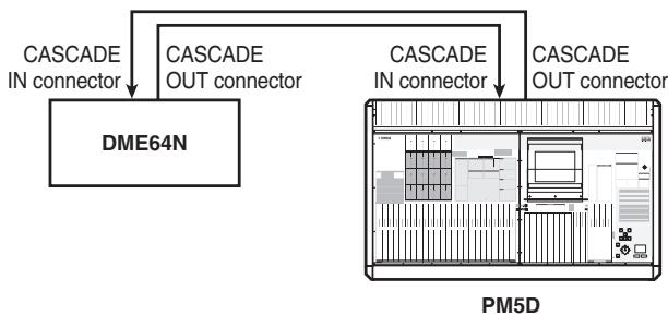
3 Uni-directional connection using the CASCADE IN/OUT connectors — 1 (DME64N only)
This method is a uni-directional connection that sends audio signals from the DME64N to the PM5D via its CASCADE IN connector.
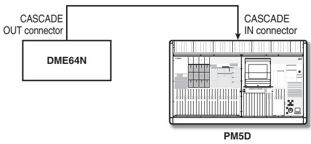
4 Uni-directional connection using the CASCADE IN/OUT connectors—2 (DME64N only)
This method is a uni-directional connection that sends audio signals from the PM5D via its CASCADE OUT connector to the DME64N.
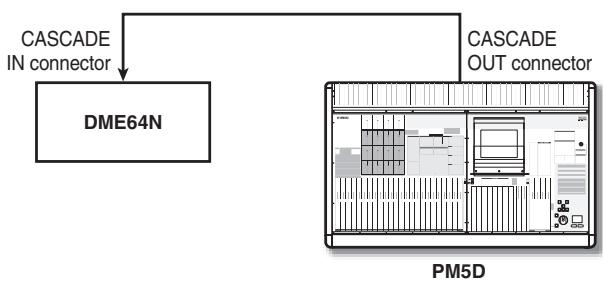
Note
When using the CASCADE IN/OUT connectors to make connections, the CASCADE IN/OUT connectors are used as the connectors, but the settings will be the same as when using slot input/output. In the CASCADE CONNECTION area of the MIXER SETUP screen (SYS/W.CLOCK function), you will need to make settings so that the CASCADE IN connector is assigned to the SLOT IN port (if using the CASCADE IN connector) or the SLOT OUT port is assigned to the CASCADE OUT connector (if using the CASCADE OUT connector).
Hint
If desired, you can control the DME series unit from the PM5D without transmitting or received audio signals. In this case, simply make one of the connections shown in examples 2-4; control signals will be sent from the PM5D to the DME.
5 Connections using the DSP5D
If the PM5D and DSP5D are cascade-connected, install a MY-16CII CobraNet card in a slot of the DSP5D (machine #2), and use an Ethernet cable to connect it to the DME series.
Note
You cannot use AuviTran's AVY16-ES EtherSound card to control the DME series from the PM5D.
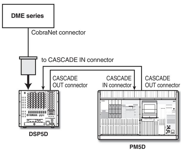
Procedure for connecting the DSP5D and DME series
Bi-directional connection via the CASCADE IN/OUT connectors (DME64N only)
This is an example of connecting the CASCADE IN and CASCADE OUT connectors of the DSP5D and DME64N respectively, so that audio signals be transferred bidirectionally.
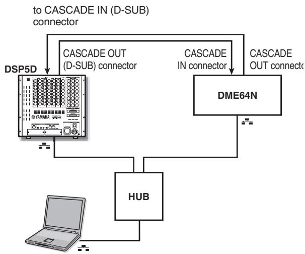
Connection using a DCU5D unit
You can use an Ethernet cable to connect the DSP5D and DME series via a DCU5D digital cabling unit.
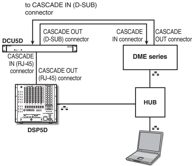
Note
The DSP5D must be connected via the CASCADE OUT (RJ-45) connector.
□ Initiating communication between the PM5D and the DME series unit
To select the port used for audio signal transmission/reception between the PM5D and the DME series unit, and to initiate communication, proceed as follows.
1 Connect the PM5D and the DME series unit.
2 In the DISPLAY ACCESS section, press the [MIDI/REMOTE] key several times to access the DME CONTROL screen.
3 In the component selection area at the upper left of the screen, select SETUP.
A screen like the following will appear.
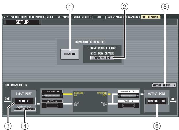
The SETUP screen contains the following items.
① CONNECT
This button initiates or terminates the connection between the PM5D and the DME series unit.
② MIDI PGM CHANGE (MIDI program change)
If this button is on, a program change message will be transmitted to the DME via the I/O card or via the
CASCADE IN/OUT connectors when a scene is recalled on the PM5D. This allows scenes to be recalled on the DME in tandem with scene recall operations on the PM5D.
(3) INPUT PORT
Here you can select the PM5D port that will receive audio signals from the DME.
④ MONITOR PORT
Here you can select the PM5D port that will receive monitor signals from the DME. Since this monitor signal is sent to the PM5D's CUE bus, the DME's monitor function can be controlled from the PM5D just like the PM5D's own cue function (EXTERNAL CUE function).
⑤ MIXER SETUP (show the MIXER SETUP screen)
This button displays the SYS/W.CLOCK function. MIXER SETUP screen.
⑥ OUTPUT PORT
Here you can select the PM5D port that will output audio signals to the DME.
4 In the INPUT PORT area located at the lower left of the screen, select the PM5D port that will receive audio signals from the DME series unit.
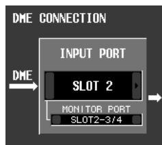
The types of port that can be selected here will depend on
the port that is currently selected for cascade input (MIXER SETUP screen CASCADE IN PORT SELECT field), as follows.
| Setting in the CAS-CADE IN PORT SELECT field (MIXER SETUP screen) | Items available in the INPUT PORT field |
| CASCADE IN | ----, SLOT1-SLOT4 |
| SLOT4 | ----, CASCADE IN, SLOT1-SLOT3 |
| SLOT3/4 | ----, CASCADE IN, SLOT1-SLOT2 |
| SLOT1-4 [CH1-8] | ----, CASCADE IN |
| SLOT1-4 [CH9-16] | ----, CASCADE IN |
Note
- You cannot switch the cascade input port setting from the DME CONTROL screen. If necessary, click the MIXER SETUP button to access the MIXER SETUP screen (SYS/W.CLOCK function), and change the port you will use for cascade input.
- Depending on the type of cascade connection, the DSP5D port will indicate only the items that can be selected: ---, SLOT1-2, CASCADE IN (D-SUB), or CASCADE OUT (RJ-45).
5 In the MONITOR PORT field, select the PM5D port that will receive monitor signals from the DME series unit.
The following ports can be selected.
----No assignment
SLOT1-1-SLOT4-16...The desired port of slot 1-4
CASCADE 1-32 .CASCADE IN ports 1-32
6 In the OUTPUT PORT field located in the lower right of the screen, select the PM5D port that will transmit audio signals to the DME.
The types of port that can be selected here will depend on the port that is currently selected for cascade output (MIXER SETUP screen CASCADE OUT PORT SELECT field), as follows.
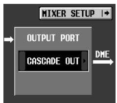
| Setting in the CAS-CADE OUT PORT SELECT field (MIXER SETUP screen) | Items available in the OUTPUT PORT field |
| CASCADE OUT | ----, SLOT1-SLOT4 |
| SLOT3/4 | ----, SLOT1-SLOT4, CASCADE OUT |
| SLOT1-4 [CH1-8] | |
| SLOT1-4 [CH9-16] |
Note
- You cannot switch the cascade output port setting from the DME CONTROL screen. If necessary, click the MIXER SETUP button to access the MIXER SETUP screen (SYS/ W.CLOCK function), and change the port you will use for cascade output.
- Depending on the type of cascade connection, the DSP5D port will indicate only the items that can be selected: ---, SLOT1-2, CASCADE OUT (D-SUB), or CASCADE OUT (RJ-45).
7 If you want scene changes on the PM5D to be linked with scene changes on the DME series unit, turn on the MIDI PGM CHANGE button in the center of the screen.
If the MIDI PGM CHANGE button is on, switching the scene on the PM5D will cause a program change message of a number corresponding to that scene to be sent to the DME.
Hint
- The above program change message is always transmitted via the I/O card or the CASCADE IN/OUT connector. This is not affected by MIDI PGM CHANGE or by the MIDI program change transmission port or transmission on/off setting selected in the MIDI SETUP screen.
- The program number assignment for each scene can be specified in the MIDI PGM CHANGE screen.
8 To initiate communication between the PM5D and the DME series unit, click the CONNECT button to turn it on.
While the CONNECT button is on, parameter operations and scene store/recall operations on the DME can be remotely controlled from the PM5D. To terminate communication, click the CONNECT button once again to turn it off.
□ Controlling DME parameters
Here's how the parameters of the DME series unit can be controlled from the PM5D. If desired, the changes you make can be saved in the scene of the DME series unit.
1 In the DME CONTROL screen, choose SETUP, and turn on the CONNECT button to initiate communication.
2 In the upper left of the screen, use the component type / component selection areas to select the component you want to control.
If a component other than SETUP is selected, internal parameters of the DME can be controlled from the PM5D screen. The following illustration is an example of when the SLOT OUTPUT component is selected.
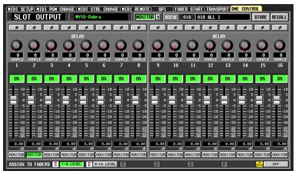
3 Use the knobs, sliders, and buttons in the screen to control the parameters of the DME series unit.
Knob, slider, and button operation methods are the same as for the PM5D's internal parameters. For details on the parameters that can be operated for each component, refer to the owner's manual of the DME series unit.
4 If you want to use DCA faders 1-8 to control the parameters of the component, click an A-F button in the ASSIGN TO FADERS area.
When you click a button A-F, the corresponding parameters will be assigned to DCA faders 1-8, and can be controlled by the faders. To return to the previous state, click the DCA button.
Hint
As an alternative to clicking the A-F buttons, you can obtain the same result by holding down the top panel [SHIFT] key and pressing the [A]-[F] keys of the FADER MODE section.
5 If you want to store your changes in a scene of the DME series unit, use the SCENE field in the upper right of the screen to select the store-destination, and click the STORE button.
The edited settings will be stored as a scene in the DME. To recall this scene, use the SCENE field in the upper right of the screen to select the scene, and click the RECALL button.
Note
When storing a DME scene from the PM5D's screen, you can only store by overwriting an existing scene on the DME; you cannot store the settings as a new scene or edit the scene name.
Hint
For a system in which only the DSP5D and DME are connected, use DSP5D Editor to specify the DSP5D port that will be connected to the DME. You can select the following connectors/slots for each port.
- INPUT PORT
CASCADE IN (D-SUB), SLOT1, SLOT2, CASCADE OUT (RJ-45)
OUTPUT PORT
CASCADE OUT (D-SUB), SLOT1, SLOT2, CASCADE OUT (RJ-45)
UTILITY function
PREFERENCE 1/2 screens
Preference settings for the PM5D are divided into two screens.
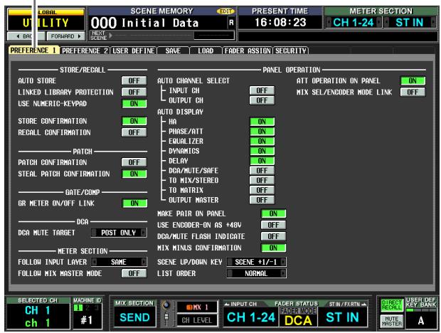
PREFERENCE 1
PREFERENCE 2
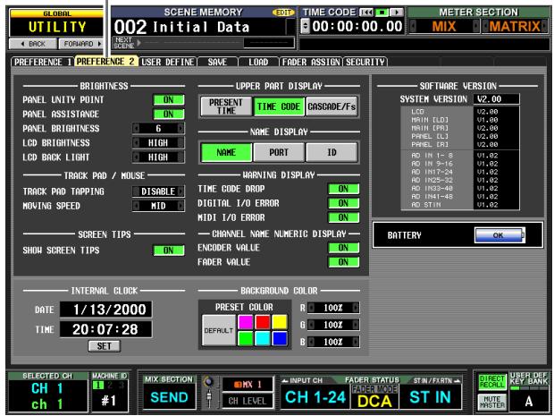
PREFERENCE 2
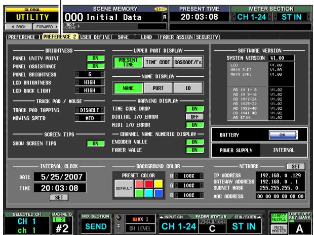
For the DSP5D
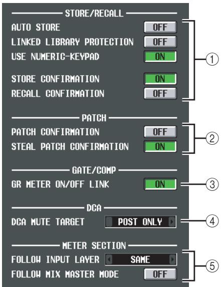
① STORE/RECALL
These buttons let you turn on/off options related to scene store/recall operations. You can select the following options.
- AUTO STORE
Turns the Auto Store function on/off. If this button is on, pressing the [STORE] button (SCENE MEMORY section) of the panel twice in succession will store the current scene in the currently selected scene number.
LINKED LIBRARY PROTECTION
If this button is on, you will be unable to overwrite or delete library items that are linked to a protected scene. This option prevents a protected scene from being modified by having an associated library item edited.
USE NUMERIC-KEYPAD
If this button is on, the numeric keypad of a PS/2 keyboard connected to the KEYBOARD connector (or a numeric keypad connected to the KEYBOARD connector) can be used to specify the scene number directly.
- STORE CONFIRMATION
- RECALL CONFIRMATION
If these buttons are on, a confirmation message will appear when you perform a Store or Recall operation respectively.
② PATCH
These buttons let you turn on/off options related to patch operations. You can select the following options.
- PATCH CONFIRMATION
If this button is on, a confirmation message will appear when you edit an input patch or output patch.
STEAL PATCH CONFIRMATION
If this button is on, a confirmation message will appear when you edit an input patch or output patch item that is already patched.
③ GATE/COMP (Gate / Compressor)
These buttons let you turn on/off options related to gating and compression.
- GR METER ON/OFF LINK
If this button is on, the GR meter will not show the reduction amount for gates/compressors that are currently off.
④ DCA MUTE TARGET
This specifies whether the DCA [MUTE] key will mute the send to the MIX bus when the send-source to the MIX bus is PRE FADER. If you specify "POST ONLY," the PRE FADER signal will not be muted. If you specify "PRE & POST," it will be muted regardless of the send-source position.
⑤ METER SECTION
Here you can set the following meter-related options.
FOLLOW INPUT LAYER
This option lets you specify how the [CH 1-24]/[CH 25-48] keys (INPUT channel strip) and [STIN 1-4]/[FXRTN 1-4] keys will select the layer that is shown by the meters in the center of the panel and the meters in the upper right of the panel. Click the l / 门 buttons at left and right to make your choice.
OFF . . . . . . . . . . . . . . . . . . . . . . . . . . . . . . . . . . . . . . . . . . . . . . . . . . . . . . . . . . . . . . . . . . . . . . . . . . . . . . . . . . . . . . . . . . . keys will not affect the content shown by the meters in the center of the panel. Pressing the [STIN 1-4]/[FXRTN 1-4] keys will not affect the content shown by the meters in the upper right of the panel.
SAME . . . . . When you press the [CH 1-24] or [CH 25-48] key, the corresponding layer will be shown by the meters in the center of the panel (if an input channel is selected in the meter section). When you press the [STIN 1-4] or [FXRTN 1-4] key, the corresponding layer will be shown by the meters in the upper right of the panel.
ALTERNATIVE ... When you press the [CH 1-24] or [CH 25-48] key, the opposite layer will be shown by the meters in the center of the panel (if an input channel is selected in the meter section). When you press the [STIN 1-4] or [FXRTN 1-4] key, the opposite layer will be shown by the meters in the upper right of the panel.
Note
- If this is set to SAME or ALTERNATIVE, the meters in the center of the panel and the meters in the upper right can be switched independently.
- If the selected layer is switched from the panel, the layer shown by the meters will also change. However if you switch the METER SECTION field in the constantly-displayed area in the upper part of the screen, the layer selected on the panel will not change.
If this button is on, pressing the MIX section [MIX MASTER] key will cause the meters in the center of the panel and the meters in the upper right of the panel to show the MIX/MATRIX channel levels. Press the MIX section [MIX SEND] key to return to the original input channel level display.
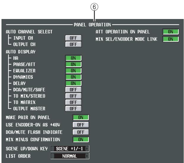
⑥ PANEL OPERATION
Here you can set the following options for panel operation.
- AUTO CHANNEL SELECT
This specifies whether the corresponding channel will be selected when you operate a channel's [ON] key, fader, or encoder. INPUT CH (input channels) and OUTPUT CH (output channels) can be turned on/off separately.
- AUTO DISPLAY
For each of the following items, you can individually specify whether the related screen will automatically appear when you use the SELECTED CHANNEL section to operate a specific parameter. The following table shows the parameters corresponding to each button and the screen that will appear.
| Button name | Corresponding parameters | Screen that appears |
| HA | Input channel head amp gain | INPUT HA/INSERT function screens |
| PHASE/ATT | Input channel phase/attenuator | INPUT EQ function ø/ATT screen |
| EQUALIZER | EQ-related param-eters | INPUT EQ/OUTPUT EQ function EQ PARAM screen |
| DYNAMICS | Gate/compressor-related parameters | INPUT GATE/COMP function or OUTPUT COMP function GATE PARAM or COMP PARAM screen |
| DELAY | Delay-related parameters | INPUT DELAY/OUT-PUT DELAY function screens |
| DCA/MUTE/SAFE | DCA group / Mute group / Recall safe-related parameters | INPUT DCA/GROUP function or OUTPUT DCA/GROUP func-tion DCA GROUP ASSIGN, MUTE GROUP ASSIGN or RECALL SAFE screen |
| TO MIX/STE-REO | TO MIX/TO STE-REO-related parameters | PAN/Routing func-tion CH to MIX screen or SURR PARAM screen, or MATRIX/ST function MATRIX/ST ROUTING screen |
| TO MATRIX | Send level to MATRIX bus | MATRIX/ST function MATRIX/ST ROUT-ING screen |
| OUTPUT MASTER | MIX/MATRIX chan- nel output level | OUTPUT VIEW func- tion FADER VIEW screen |
MAKE PAIR ON PANEL
If this button is on, you can use the [SEL] keys to set/ defeat pairing. In Horizontal Pair mode, you can set/ defeat pairing by simultaneously pressing the [SEL] keys of two pairable channels. In Vertical Pair mode, you can set/ defeat pairing by holding down the [SHIFT] key and pressing the [SEL] key of one of the channels. (For more about pair modes p.53)
USE ENCODER-ON AS +48V
If this button is on, the ENCODER [ON] key located above the encoder will turn the phantom power (+48V) on/off when HA (head amp input sensitivity) is selected as the encoder mode.
DCA/MUTE FLASH INDICATE
If this button is on, the DCA [MUTE] key LED and the DCA assign LED for channels belonging to that DCA group will blink when you turn on a DCA [MUTE] key (DCA section).
If this button is on, a confirmation message will appear when you execute the Mix Minus setting (hold down the [SEL] key of an input channel and press the [SEL] key of a MIX channel) from the panel.
- SCENE UP/DOWN KEY
This specifies what the SCENE MEMORY [ ] / [ ] keys will do when pressed in the SCENE screen. You can choose one of the following two operations.
SCENE +1 / - 1 . Pressing the SCENE MEMORY [A] key will select the next highest-numbered scene, and pressing the SCENE MEMORY [V] key will select the next lowest-numbered scene. (Key presses will increment/decrement the scene number.)
LIST UP/DOWN .. Pressing the SCENE MEMORY [▲] key will scroll the list upward, and pressing the SCENE MEMORY [▼] key will scroll the list downward. (Key presses will scroll the list upward/downward.)
LIST ORDER
This specifies the order in which scene memories and library items will appear in the screen.
NORMAL . Show the list in ascending numerical order.
REVERSE . Show the list in descending numerical order.
If this button is on, you will be unable to use the panel encoders to operate the attenuator.
- MIX SEL/ENCODER MODE LINK
If this button is on, using the panel [SEL] keys or on-screen operations to select MIX channels 1-24 will select the MIX SEND SELECT [1]-[24] keys of the FADER FLIP ENCODER MODE section in tandem. In the same way, pressing MIX SEND SELECT [1]-[24] keys will select MIX channels 1-24.
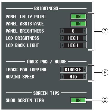
PREFERENCE screen 2
⑦ BRIGHTNESS
Here you can make settings for the brightness of the panel LED and LCD displays.
- PANEL UNITY POINT
If this button is on, LEDs corresponding to a specific reference value (e.g., 0 dB or CENTER) will light more brightly than usual. However, this is valid only if PANEL BRIGHTNESS is set to 5 or less.
- PANEL ASSISTANCE
If this button is on, even LEDs that should be off will stay dimly lit so that you can tell their location even in a dark environment. However, this is valid only if PANEL BRIGHTNESS is set to 5 or less.
PANEL BRIGHTNESS
This adjusts the brightness of all panel LEDs in a range of 1-8.
LCD BRIGHTNESS
You can adjust the brightness of the LCD display in a three-step range: HIGH, MID, or LOW.
LCD BACK LIGHT
You can adjust the brightness of the LCD display backlight in a two-step range: HIGH or LOW.
⑧ TRACK PAD/MOUSE
Here you can make settings for the built-in track pad or a PS/2 mouse connected to the MOUSE connector.
- TRACK PAD TAPPING
This enables/disables the Tapping function (a function that lets you perform the track pad left-click operation by tapping quickly on the track pad).
- MOVING SPEED
This selects the speed at which the cursor in the screen will move when you operate the built-in track pad or a PS/2 mouse connected to the MOUSE connector. Choose one of three speeds; FAST, MID, or SLOW.
⑨ SCREEN TIPS
SHOW SCREEN TIPS
If this button is on, moving the cursor onto an item in the screen and waiting for a short time will (in some cases) display a "screen tip" reminding you of the operation. The screen tip is displayed when you open the JOB SELECT window by holding down the [SHIFT] key and pressing the [ENTER] key, or when you need to press the [ENTER] key to finalize an edited value.
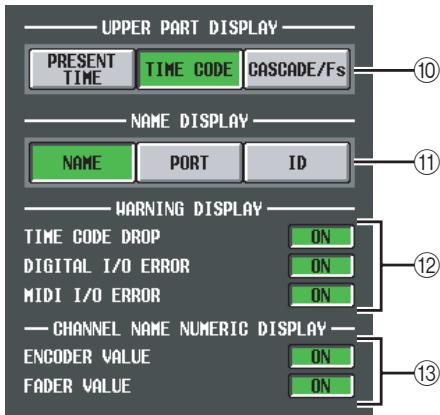
UPPER PART DISPLAY
These buttons select the item that is shown in the center right (to the right of the scene memory indication) of the upper part of the display (the constantly displayed area).
- PRESENT TIME
Indicates the present time.
TIME CODE
Indicates the internal time code being generated by the PM5D, or the time code being received from an external device. This is the same as the time code shown in the SCENE function EVENT LIST screen.
- CASCADE/Fs
Indicates the master/slave status when using a cascade connection, and the sampling frequency at which the PM5D system is currently operating.
Hint
You can also cycle through these choices by clicking in this display section.
NAME DISPLAY ([NAME] indicator display)
Choose one of the following as the content that will be shown by the [NAME] indicators of the INPUT channel strip and DCA strip.
NAME
The indicators will show the names assigned to the input channels / DCA groups in the NAME screen (INPUT PATCH function). ( p.282)
- PORT
For input channels, the indicators will show the name of the currently assigned port. For DCA groups, the indicators will show the ID number.
- ID
For both input channels and DCA groups, the indicators will show the fixed ID number.
⑫ WARNING DISPLAY
Here you can select whether a warning will be displayed when the following problems occur.
TIME CODE DROP
When time code (LTC, MTC) being received from an external device is dropped.
DIGITAL I/O ERROR
When a DIO error is detected.
MIDI I/O ERROR
When a MIDI error is detected.
⑬ CHANNEL NAME NUMERIC DISPLAY
- ENCODER VALUE
When you operate an encoder (pan setting), the name display will switch to indicating that value.
- FADER VALUE
When you operate a fader, the name display will switch to indicating that value.
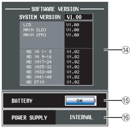
SOFTWARE VERSION
This indicates the version of the unit's operating software (firmware).
15 BATTERY
This indicates the voltage of the internal battery.
16 POWER SUPPLY (DSP5D only)
This indicates the status of the DSP5D's power supply. This will indicate "INTERNAL" if the DSP5D is operating on its internal power supply, or "EXTERNAL" if it is operating on the PW800W external power supply.
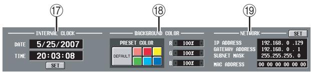
17 INTERNAL CLOCK
This indicates the year/month/day (DATE) and time (TIME) of the internal clock.
If you want to change the setting, click the SET button.
18 BACKGROUND COLOR
This specifies the screen background color for each machine. If the PM5D and DSP5D are cascade-connected, having a different background color will make it easier to distinguish the machines when you switch between them for control.
19 NETWORK (DSP5D only)
Here you can make network settings used when the DSP5D's [NETWORK] connector is connected to your computer via an Ethernet cable (p.159).
USER DEFINE screen
Here you can assign functions to the User Defined keys (USER DEFINED [1]–[25] keys).
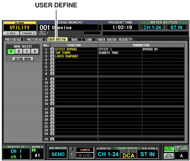
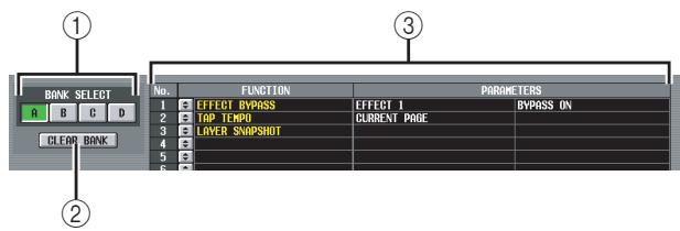
① BANK
Select a bank A-D (groups of functions assigned to the User Defined keys).
② CLEAR BANK
Clearly the currently selected bank.
③ List
This area lists the functions and option parameters assigned to the User Defined keys in the currently selected bank.
To edit the settings, click the button at the left to open the USER DEFINED KEY ASSIGN window, and select the function and parameter from the following table.
| FUNCTION | PARAMETER 1 | PARAMETER 2 | Explanation |
| NO ASSIGN | — | — | No assignment |
| SCENE | INC RECALL | — | Recall the scene of the next existing number. |
| DEC RECALL | — | Recall the scene of the previous existing number. | |
| DIRECT RECALL | SCENE #000-#500 | Directly recall the scene of the specified number | |
| EVENT LIST | TIME CODE [RTN TO START] | — | The same functions as the RETURN TO START TIME, STOP, and PLAY buttons displayed when INTERNAL is selected as the time code source in the EVENT LIST screen |
| TIME CODE [STOP] | |||
| TIME CODE [PLAY] | |||
| TIME CODE [INSERT] | The same function as the TIME CODE INSERT button in the EVENT LIST screen | ||
| AUTO CAPTURE ON | The same function as the AUTO CAPTURE button in the EVENT LIST screen | ||
| DIRECT EVENT RECALL | EVENT #000-#999 | Recall the specified event registered in the EVENT LIST screen | |
| NEXT EVENT RECALL | — | Recall the next-numbered event | |
| PREV EVENT RECALL | Recall the previous-numbered event | ||
| ENABLE/DISABLE | Switch the ENABLE button and DISABLE button in the EVENT LIST screen | ||
| ENABLE [ALL MANUAL]/ DISABLE | Switch the ENABLE [ALL MANUAL] button and DISABLE button in the EVENT LIST screen | ||
| EFFECT LIBRARY | DIRECT RECALL → EFFECT 1–8 | INC RECALL | Recall the next-numbered library item into effect 1–8 |
| DEC RECALL | Recall the previous-numbered library item into effect 1–8 | ||
| LIBRARY #001-#199 | Recall the library item of the specified number into effect 1–8 | ||
| EFFECT BYPASS | EFFECT 1-EFFECT 8 | BYPASS ON | Bypass the specified effect |
| INPUT CH LIBRARY | DIRECT RECALL | LIBRARY #000-#199 | Recall the library item of the specified number into the selected channel/GEQ module |
| OUTPUT CH LIBRARY | |||
| GATE LIBRARY | LIBRARY #001-#199 | ||
| COMP LIBRARY | |||
| INPUT EQ LIBRARY | |||
| OUTPUT EQ LIBRARY | |||
| INPUT PATCH LIBRARY | LIBRARY #00-#99 | ||
| OUTPUT PATCH LIBRARY | |||
| HA LIBRARY | LIBRARY #000-#199 | ||
| GEQ LIBRARY | DIRECT RECALL → GEQ 1–20 | ||
| TRACKING RECALL | ENABLE/DISABLE | — | The same function as the ENABLED/DISABLED button in the TRACKING RECALL screen |
| OFFSET LOCK | The same function as the OFFSET LOCK button in the TRACKING RECALL screen | ||
| SELECTED CH ON | Switch the Tracking Recall function on/off for the currently selected channel | ||
| TALKBACK ASSIGN | SELECTED CH ASSIGN | — | When an output channel is selected, turn talkback transmis-sion on/off for that channel |
| DIRECT ASSIGN | MIX 1–24, MATRIX 1–8, STEREOL A/L/R, STE-REO B L/R | Send the talkback signal to the specified output channel | |
| MONITOR | DIRECT ASSIGN | MIX 1–24, MATRIX 1–8 | Monitor the desired MIX/MATRIX channel *1 |
| DIMMER ON | — | Switch on the monitor dimmer function | |
| TAP TEMPO | CURRENT PAGE | — | Control the Tap Tempo function in the displayed screen |
| EFFECT 1-EFFECT 8 | Control the Tap Tempo function of the specified effect | ||
| ALL EFFECTS | Control the Tap Tempo function of all effects that have a TEMPO parameter | ||
| SURROUND PAN | GRAB | SELECTED CH, ODD CH, EVEN CH | Use a joystick assigned to GPI to begin controlling the sur-round pan of the corresponding channel |
| NAME DISPLAY | NAME → PORT → ID | — | Each time you press the key, the [NAME] indicator for each fader will cycle through the channel name → port name → ID (channel number) |
| ID | UNLATCH | The [NAME] indicator for each fader will show the ID (chan-nel number) only while you hold down the key | |
| PORT | The [NAME] indicator for each fader will show the port name only while you hold down the key | ||
| NAME | The [NAME] indicator for each fader will show the channel name only while you hold down the key | ||
| PAGE CHANGE | PAGE BACK | — | Display the screen that you used immediately prior to the current screen |
| PAGE FORWARD | Display the screen that you used immediately after the cur- rent screen | ||
| PAGE BOOKMARK | Memorize the currently selected screen (hold down the key for two seconds or longer), or display the last-memorized screen (press and release the key within two seconds)2 | ||
| GEQ PARAM PAGE | GEQ 1–20 | Display the GEQ PARAM screen | |
| EFFECT PARAM PAGE | EFFECT 1–8 | Display the EFFECT PARAM screen | |
| NEXT TAB | Display the next screen within the currently selected function | ||
| PREVIOUS TAB | Display the previous screen within the currently selected function | ||
| LAYER SNAPSHOT | — | — | Memorize the state of the layer assigned to the panel (hold down the key for two seconds or longer), or display the last-memorized layer (press and release the key within two sec- onds)*3 |
| DIRECT RECALL/ MUTE MASTER | MODE CHANGE | LATCH | Switch the function of the SCENE MEMORY [1]–[8] keys (DIRECT RECALL / MUTE MASTER) each time you press the User Defined key |
| UNLATCH | The SCENE MEMORY [1]–[8] keys will function as DIRECT RECALL while you hold down the User Defined key | ||
| USER DEFINED KEY BANK | NEXT BANK | — | Switch to the next bank of User Defined key assignments |
| PREVIOUS BANK | Switch to the previous bank of User Defined key assign- ments | ||
| DIRECT SELECT | BANK A-D | Switch to the desired bank of User Defined key assignments | |
| MIDI DIRECT OUT | MIDI NOTE | C-2-G 8 | When you press the key, transmit a note-on message with the specified note number and a velocity of 127 When you release the key, transmit a note-on message of the same note number with a velocity of 0 (= note-off)4 |
| MIDI PGM CHANGE | 1–128 | When you press the key, transmit a program change mes-sage with the specified number *4 | |
| MIDI CTRL CHANGE | 0–119 | When you press the key, transmit a control change message with the specified control number and a value of 127 When you release the key, transmit a control change message of the same control number with a value of 0*4 | |
| MACHINE CONTROL | SET LOCATION, RS-422 REC, RS-422 PLAY, RS-422 STOP, RS-422 FF, RS-422 REW, RS-422 LOCATE 1–20 | — | Transmit the specified RS422/MMC command from the RS422 REMOTE connector or the currently-valid MIDI port (the SET LOCATION command is common to RS422 and MMC) |
| MMC REC, MMC PLAY, MMC STOP, MMC FF, MMC REW, MMC LOCATE 1–20 | MMC ID= 1–127, ALL | ||
| GPI OUT CONTROL | PORT 1–12 | LATCH | Switch the specified GPI OUT port between active/inactive each time you press the key |
| UNLATCH | Switch the specified GPI OUT port to inactive while you hold down the key | ||
| PM5D EDITOR CON- TROL | *5 | *5 | Switch windows in PM5D Editor on a PC |
| SET NOMINAL LEVEL | — | — | If you hold down this key and press the [SEL] key, the fader of that channel will be set to nominal level. (While you hold down this key, only the [SEL] keys of channels not at nominal level will light.) Alternatively, you can set the level to nominal level by moving the cursor to an on-screen knob (level, EQ gain) or fader, and then pressing the [ENTER] key while holding down this key. |
| SET DEFAULT VALUE | — | — | If you move the cursor to an on-screen knob or fader, and then press the [ENTER] key while holding down this key, the control will return to its default value |
| ENCODER MODE KEY | PAN | — | Same function as the [PAN] key in the top panel ENCODER MODE section |
| GAIN/ATT | Same function as the [GAIN/ATT] key in the top panel ENCODER MODE section | ||
| ALT LAYER | Same function as the [ALT LAYER] key in the top panel ENCODER MODE section | ||
| MIX SEND | 1-24 | Same function as the MIX SEND SELECT [1]-[24] keys in the top panel ENCODER MODE section | |
| FADER FLIP | — | Same function as the [FLIP] key in the top panel FADER FLIP section | |
| SELECTED CH | INSERT ON/OFF | — | Turns insert on/off for the selected channel |
| STEREO STRIP SECTION | STEREO A, STEREO B | MONITOR, CUE | Select either STEREO A/B channels, Monitor, or Cue as the function controlled by the STEREO A/B channel strip's STE-REO fader and [ON] key Dark: Monitor or CUE is enabled Lit: STEREO A/B channels are enabled |
| DSP5D CONTROL | MACHINE SELECT | #1(PM5D), #2(DSP5D), #3(DSP5D) | Select the PM5D or DSP5D (#2 or #3) as the machine that will be controlled by panel operations (Lit if the specified machine is selected) |
| CH STRIP LAYER DIRECT | #1(PM5D) CH1-24, #1(PM5D) CH25-48, #2(DSP5D) CH1-24, #2(DSP5D) CH25-48, #3(DSP5D) CH1-24, #3(DSP5D) CH24-48, #1(PM5D) STIN1-4, #1(PM5D) FX RTN1-4, #2(DSP5D) STIN1-4, #2(DSP5D) FX RTN1-4, #3(DSP5D) STIN1-4, #3(DSP5D) FX RTN1-4 | Switch the INPUT channel strip or ST IN/FX RTN channel strip to a layer of the desired machine (Lit if the specified layer is selected) |
1. The corresponding channel will be selected in the DEFINE field of the MONITOR screen, and the monitor source will switch to DEFINE.
2. The LED will light for User Defined keys for which a screen has been memorized. The column in the right of the list in the USER DEFINE screen shows the name of the memorized screen.
3. Layers that can be memorized include the following items.
- The layer selected in the INPUT channel strip (CH 1-24, CH 25-48, MIDI REMOTE)
- The layer selected in the ST IN/FX RTN channel strip (ST IN 1-4, FX RTN 1-4, MIDI REMOTE)
- The layer shown by the DCA channel strip (DCA, A-F, GEQ)
- If the DCA channel strip is controlling GEQ, the GEQ module number and band
- The encoder mode selected by ENCODER MODE (SEND, PAN, HA, ATT, ALT)
- The FADER FLIP status
- The currently selected MIX send
- The mode selected in the MIX section (MIX SEND, MIX MASTER)
- The source selected in the METER section (CH 1-24 ST IN, CH 25-48 ST IN, MIX/MATRIX)
4. The output port and MIDI channel can be specified in the MIDI SETUP screen.
*5. This parameter specifies the PM5D Editor window that you want to control. If the specified window is closed or inactive, the window will be opened and made active. If the specified window is already open and active, the window will be closed.
Note
During PREVIEW mode, the following USER DEFINE functions that affect internal signal processing are disabled; EVENT LIST, TALKBACK ASSIGN, MONITOR, MIDI DIRECT OUT, MACHINE CONTROL, and GPI OUT CONTROL.
SAVE screen
Here you can save PM5D scenes and library data on a memory card inserted in the MEMORY CARD slot. This cannot be used while in PREVIEW mode.
Hint
If the PM5D and DSP5D are cascade-connected, the settings of each machine can be consecutively saved by a single operation.
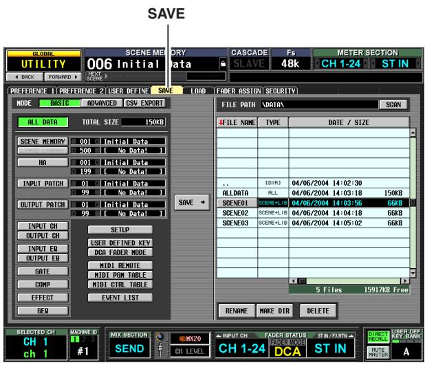

① MODE
Choose one of the following as the mode in which files will be saved: BASIC, ADVANCED, CSV EXPORT. The left side of the screen will change according to the mode you select.
BASIC mode
In BASIC mode you can save all scene memory and library data (or just a selected portion of data) to a card. If BASIC is selected, the left side of the screen will show the items listed in the following table.
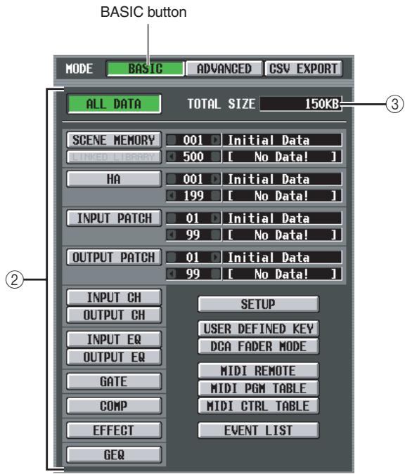
(2) Select the items to save
Choose one of the following to specify the data that will be saved.
| Button | Content |
| ALL DATA | All items of each type, and the contents of the current scene |
| SCENE MEMORY | Contents of scene memory |
| LINKED LIBRARY | Libraries linked to the scene (available only if the SCENE MEMORY button is on) |
| HA | Contents of the HA library |
| INPUT PATCH | Contents of the input patch library |
| OUTPUT PATCH | Contents of the output patch library |
| INPUT CH | Contents of the input channel library |
| OUTPUT CH | Contents of the output channel library |
| INPUT EQ | Contents of the input EQ library |
| OUTPUT EQ | Contents of the output EQ library |
| GATE | Contents of the gate library |
| COMP | Contents of the compressor library |
| EFFECT | Contents of the effect library |
| GEQ | Contents of the GEQ library |
| SETUP | Various settings not saved in a scene |
| USER DEFINED KEY | User Defined key settings |
| DCA FADER MODE | Fader mode settings |
| MIDI REMOTE | MIDI remote settings |
| MIDI PGM TABLE | Contents of the list in the MIDI PGM CHANGE screen |
| MIDI CTRL TABLE | Contents of the list in the MIDI CTRL CHANGE screen |
| EVENT LIST | Contents of the list in the EVENT LIST screen |
If the SCENE MEMORY, HA, INPUT PATCH, or OUTPUT PATCH button is on, you can use the box at the right to specify the starting number and ending number of the scenes or library items that will be saved.
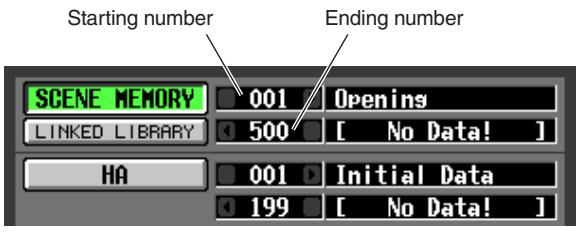
Hint
If the specified range of numbers includes empty scenes or library items, the correspondingly-numbered scenes or library items will be empty when that data is loaded.
(3) TOTAL SIZE
Indicates the file size of the currently selected item(s) (common to all modes).
ADVANCED mode
In this mode you can select either scene memory or a library, specify a starting number and ending number, and save the specified range of data on a card. If desired, you can also specify that the starting number be shifted forward or backward when the data is saved. If ADVANCED is selected, the left side of the screen will show the following items.
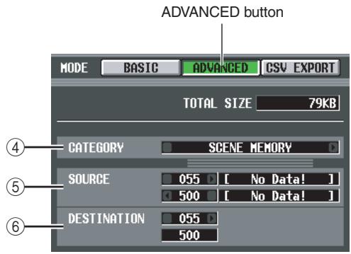
(4) CATEGORY
Indicates the category of data that is selected for saving; scene memories or library data. Click the l buttons at left and right to change the category.
⑤ SOURCE (save-source numbers)
This area shows the starting and ending number (and the corresponding scene names or library titles) of the scene memories or library items that will be saved on the card. Click the 4 / 5 buttons at the left and right of each box to change the number.
DESTINATION (save-destination number)
This area shows the starting and ending number (and the corresponding scene names or library titles) with which the data will be saved on the card. If you want to save the data to the card with a different range of numbers, click the 1 / 2 buttons at the left and right of the starting number box. (The value in the ending number
box will change automatically as the starting number is edited.)

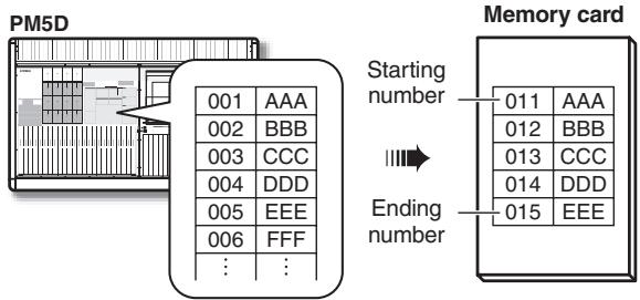
CSV EXPORT mode
In this mode you can select items such as scene memory or library titles, or channel names, and write them to a card as a separate CSV format file for each item. If CSV EXPORT is selected, the left side of the screen will show the items listed in the following table.
If a DSP5D (machine #2 or #3) is selected as the target of control, CSV files can't be written. If you need to write a CSV file, please use DSP5D Editor.
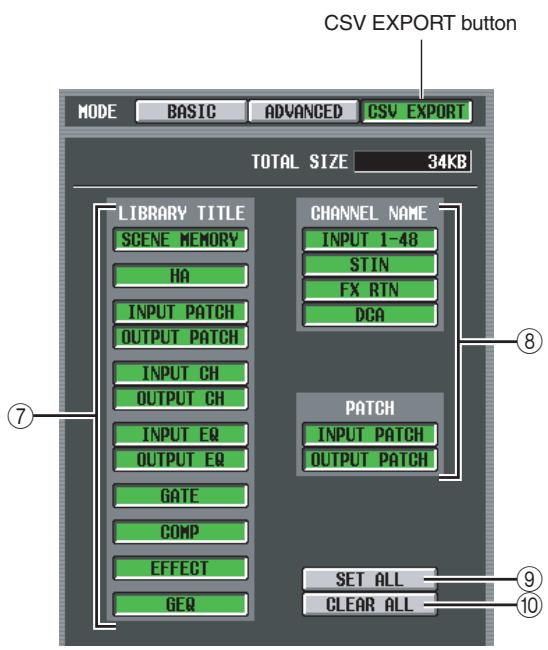
Note
⑦ LIBRARY TITLE
(8) CHANNEL NAME
From the following table, select the parameters that will be written (e.g., library title, channel name).
| Button | Content | |
| LIBRARY TITLE | SCENE MEMORY | Scene memory names |
| HA | HA library titles | |
| INPUT PATCH | Input patch library titles | |
| OUTPUT PATCH | Output patch library titles | |
| INPUT CH | Input channel library titles | |
| OUTPUT CH | Output channel library titles | |
| INPUT EQ | Input EQ library titles | |
| OUTPUT EQ | Output EQ library titles | |
| GATE | Gate library titles | |
| COMP | Compressor library titles | |
| EFFECT | Effect library titles | |
| GEQ | GEQ library titles | |
| CHANNEL NAME | INPUT 1-48 | Input channel names |
| ST IN | ST IN channel names | |
| FX RTN | FX RTN channel names | |
| DCA | DCA names | |
| PATCH | INPUT PATCH | Input patch connection status |
| OUTPUT PATCH | Output patch connection status | |
Hint
Files saved in CSV format can be edited using a word processor or spreadsheet software on a computer, and loaded back into the PM5D. However, it is possible to reload the file back into the PM5D if you change the syntax, file format, or file name. If you use Microsoft Excel to edit these files, use the Data menu to import the CSV file, and use the Text File Wizard to delete the character string quotation ("). (If you fail to do so, symbols such as "-" and "+" will not be displayed correctly.)
(9) SET ALL
Selects all LIBRARY TITLE / CHANNEL NAME items.
10 CLEAR ALL
De-selects all items.
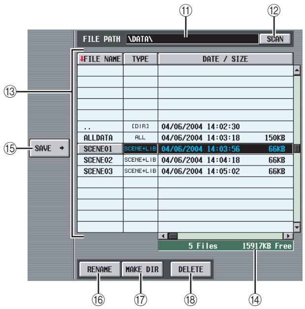
⑪ FILE PATH
Indicates the directory (folder) that is currently selected on the memory card inserted in the MEMORY CARD slot, and the location of the file. (The directory name is delineated by “\” characters.)
⑫ SCAN
This scans the directory that is currently selected on the memory card, and displays the contents in the file list (13).
⑬ File list
This area shows the files/directions contained in the current directory. The currently selected file/direction is always shown in the middle line. (The TYPE and DATE SIZE fields will be highlighted.)
The list is divided into four columns; FILE NAME, TYPE, DATE/SIZE, and COMMENT. (To see the COMMENT field, use the scroll bar to scroll the list toward the right.)
The headings at the top of each column of the list also function as buttons to sort the list. When you click these buttons, the list will be sorted in ascending or descending order for that item. The text of the currently selected button will change to red, and an arrow indicating ascending () or descending () order will appear.
These columns display the following content.
- FILE NAME
These are the names of the files/directions saved in the currently selected directory. If a lower directory is selected, you can move to that directory by clicking the directory name shown in this column.
| BAND#1 | SCENE+LIB | 02/27/2004 03:18:40 111KB |
| BAND#2 | SCENE+LIB | 02/27/2004 03:18:56 111KB |
| BAND#3 | SCENE+LIB | 02/27/2004 03:19:10 111KB |
| PATCH | DIR | 02/27/2004 03:20:14 |
| REHENSE | SCENE MEM | 02/27/2004 03:19:40 108KB |
| .. | [DIR] | 02/27/2004 03:20:14 |
| PATCH#1 | IN PATCH | 02/27/2004 03:24:40 3KB |
| PATCH#2 | IN PATCH | 02/27/2004 03:25:12 3KB |
| PATCH#3 | IN PATCH | 02/27/2004 03:25:26 3KB |
If a higher directory is selected, this column will show a "... symbol. You can click this symbol to return to that directory.
| ... | [DIR] | 02/27/2004 03:20:14 |
| PATCH#1 | IN PATCH | 02/27/2004 03:24:40 3KB |
| PATCH#2 | IN PATCH | 02/27/2004 03:25:12 3KB |
| PATCH#3 | IN PATCH | 02/27/2004 03:25:26 3KB |
| BAND#1 | SCENE+LIB | 02/27/2004 03:18:40 111KB |
| BAND#2 | SCENE+LIB | 02/27/2004 03:18:56 111KB |
| BAND#3 | SCENE+LIB | 02/27/2004 03:19:10 111KB |
| PATCH | [DIR] | 02/27/2004 03:20:14 |
| REHEASE | SCENE MEM | 02/27/2004 03:19:40 108KB |
- TYPE
This indicates the type of data that is saved. In the case of a directory, this column will indicate [DIR]. Data that cannot be used by the PM5D is indicated as UNKNOWN.
DATE / SIZE
This shows the date on which the file was last saved, and its size. In the case of a directory, only the date of creation is displayed.
COMMENT
This displays comments (up to 32 characters) stored for the files on the memory card. To create or edit a comment, click the COMMENT field of the file selected in the list to open the FILE COMMENT EDIT window.
Number of files / Free area
This displays the number of files and directories in the current directory, and the free area on the memory card.
Note
A maximum of 99 files and directories can be displayed in the file list. If there are more than 99, a blinking message of "Too Many Files" will be displayed. In this case, please delete unneeded files or move files to another directory.
15 SAVE
This saves the data selected in the left side of the screen to the currently selected directory. When you click this button, the FILE NAME EDIT window will appear, allowing you to assign a filename of up to eight characters and save the file.
Note
- If an identically-named file exists in that directory, a message will warn you that you will be overwriting the file. If you don't want to overwrite the existing file, you can either change the filename or select a different directory in which to save the file.
- When you execute the Save operation in CSV EXPORT mode, a new directory will be created within the current directory of the memory card, and a CSV file for each selected item will be created in the new directory.
- The name of the CSV file is fixed for each type of data, and cannot be changed. The newly created directory will have the name you specified when saving.
16 RENAME
This button lets you rename the currently selected file or directory. When you click this button, the FILE NAME EDIT window will appear, allowing you to edit the name.
17 MAKE DIR (Make directory)
This button creates a new sub-directory within the currently selected directory. When you click this button, the DIR NAME EDIT popup window will appear, allowing you to specify a name for the new directory.
18 DELETE
This button deletes the currently selected file or directory. When you click this button, the FILE DELETE window will appear, asking you to confirm the deletion.
Note
- A deleted file cannot be recovered.
- If you attempt to delete a directory that contains files, a warning message will appear, and the operation cannot be executed. Before deleting a directory, you must first delete any files it contains.
Note
- As memory cards, the PM5D can use either PCMCIA Type II flash ATA cards or CompactFlash media inserted in a PC card adaptor (power supply voltage of 3.3V/5V in either case). Operation is not guaranteed for any other type of media.
- Normally, the above cards are sold in an already-formatted state, so formatting will not be necessary. If you need to format a card, use a computer or other external device to format the card in FAT16 format.
LOAD screen
In this screen, scene or library data from a memory card inserted in the MEMORY CARD can be loaded into the PM5D. This cannot be used while in Preview mode.
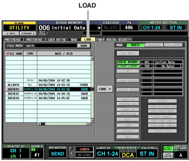
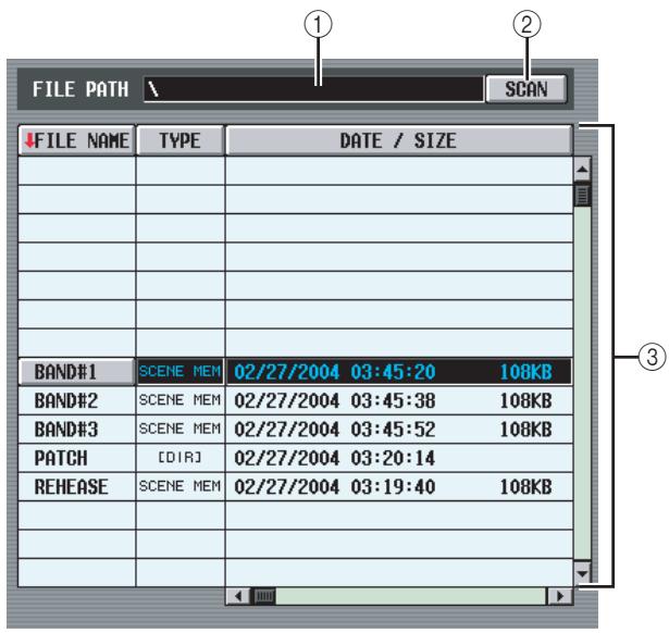
① FILE PATH
Indicates the location of the directory (folder) or file that is currently selected on the memory card. (The directory name is delineated by “\” characters.)
② SCAN
This scans the directory that is currently selected on the memory card, and displays the contents in the file list (③).
③ File list
This area shows the files/directions contained in the current directory. The currently selected file/direction is always shown in the middle line. (The TYPE and DATE SIZE fields will be highlighted.)
The list is divided into four columns; FILE NAME, TYPE, DATE/SIZE, and COMMENT. (To see the COMMENT field, use the scroll bar to scroll the list toward the right.) The contents of each column are the same as in the SAVE screen ( p.213).
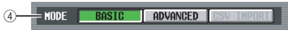
④ Mode
Here you can select the mode in which files will be loaded. If a file other than CSV is selected in the file list, you will be able to select BASIC mode or ADVANCED mode. (The CSV button will be grayed-out and unavailable.)
If a CSV file or directory is selected in the file list, CSV IMPORT mode will be selected automatically. (The BASIC and ADVANCED buttons will be grayed-out and unavailable.)
The right side of the screen will change as follows according to the currently selected mode.
BASIC mode
In BASIC mode you can load all scene memory and library data (or just a selected portion of data) from a card. If BASIC is selected, the right side of the screen will show the following items.
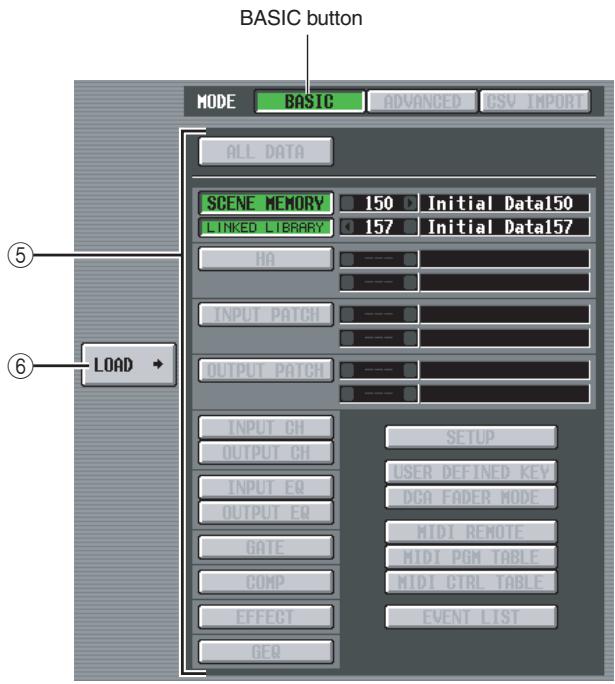
⑤ Select the data to be loaded
Here you can select the data that will be loaded. The contents of each item are the same as in BASIC mode of the SAVE screen (p.211). However, the items that can be selected will depend on the currently selected file. Buttons for items that cannot be loaded will be grayed-out and unavailable.
If the SCENE MEMORY, HA, INPUT PATCH, or OUTPUT PATCH button is on, you restrict the scenes or library items that will be loaded by using the box at the right to specify the starting number and ending number.
Hint
If the data saved on the card includes empty scenes or library items, the corresponding scenes or library items will be empty when the data is loaded.
⑥ LOAD
This button loads the data selected in the left side of the screen into the parameters you specify. When you click this button, a message will ask you to confirm the Load operation. (This is common to all modes.)
Note
If cascade connection is enabled, you can't execute the load operation.
ADVANCED mode
In this mode you can select either scene memory or a library, specify a starting number and ending number, and load the specified range of data from the card.
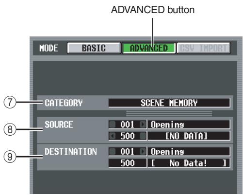
⑦ CATEGORY
This indicates the type of data (scene memory or library) saved in the currently selected file.
⑧ SOURCE (load-source)
This area shows the starting and ending number (and the corresponding scene names or library titles) of the scene memories or library items that will be loaded from the card. Click the 4 / 5 buttons at the left and right of each box to change the number.
DESTINATION (load-destination)
If you've changed the starting number of the load-destination, this area shows the starting and ending number (and the corresponding scene names or library titles) of the PM5D's internal scene memories or library items into which the data selected in the SOURCE area will be loaded. To edit the setting, click the / buttons located at the left and right of the starting number box. (The ending number value will change automatically as you edit the starting number.)

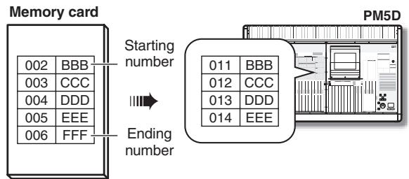
Hint
- Even if you've selected data that was saved in BASIC mode, you can switch to ADVANCED mode and load only specific numbers.
- However, an exception is that if the selected data was saved as ALL DATA or SCENE MEMORY+LINKED LIBRARY in BASIC mode, the ADVANCED button will be grayed-out, and you will not be able to switch to ADVANCED mode.
Note
You cannot load from a memory card if LOAD LOCK is turned on in the UTILITY function SECURITY screen.
CSV IMPORT mode
If a CSV file or directory is selected, CSV IMPORT mode will be selected automatically. The selected CSV file (or CSV files in the selected directory) will be searched, and the following items will appear in the right of the screen.
Note
If a DSP5D (machine #2 or #3) is selected as the target of control, CSV files can't be loaded. If you need to load a CSV file, please use DSP5D Editor.
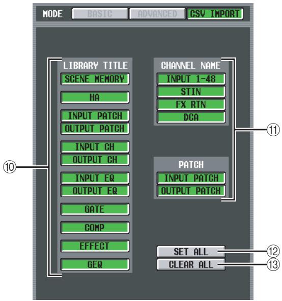
10 LIBRARY TITLE
⑪ CHANNEL NAME
Use these buttons to select the data you want to load (e.g., library titles or channel names). (The contents of each item are the same as in the SAVE screen.)
However, you will only be able to select items that match the CSV file (or the CSV files in the directory) selected in the list for loading. The buttons for other items will be grayed-out and unavailable.
12 SET ALL
This button selects all available items for loading.
⑬ CLEAR ALL
De-selects all items.
Note
Note that the screen will automatically switch to CSV IMPORT mode even if the directory selected in the list does not contain an appropriate CSV file. (In this case, all buttons will be grayed-out.)
FADER ASSIGN screen
Here you can assign the desired input channels / output channels to the eight faders in the DCA section of the panel. Here you can also assign the machine, INPUT channel layer, and ST IN/FX RTN layer that will be switched in tandem with the FADER MODE.
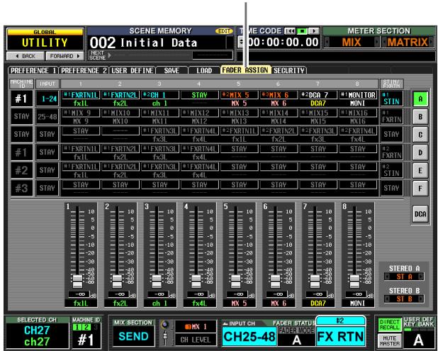
FADER ASSIGN
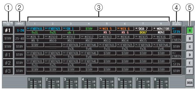
① MACHINE ID
This assigns a machine ID number (#1--#3) that will be the target of panel operations. If you select "STAY" the machine will not change.
② INPUT
This assigns the layer that will be operated by the INPUT channel strip. You can select 1-24 or 25-48. If you select "STAY" the layer will not change.
(3) 1-8 (DCA faders 1-8)
Here you can assign the channel that will be operated by each fader. You can select CH 1-48, STIN1L-STIN4R, FXRTN1L-FXRTN4R, MIX1-24, MATRIX1-8, DCA1-8, MONITOR LEVEL, or CUE LEVEL of each machine. If you select "STAY" the faders will not change. If you select "----," the faders will be disabled.
④ ST IN/FX RTN
This assigns the layer that will be operated by the ST IN/FX RTN channel strip. You can select either ST IN or FX RTN of each machine. If you select "STAY" the machine will not change.
⑤ FADER MODE
Indicates the currently selected fader mode (layer A-F, DCA). You can also click the buttons to switch the fader mode directly. The machine, INPUT channel strip, DCA faders, and ST IN/FX RTN channel strip will change.
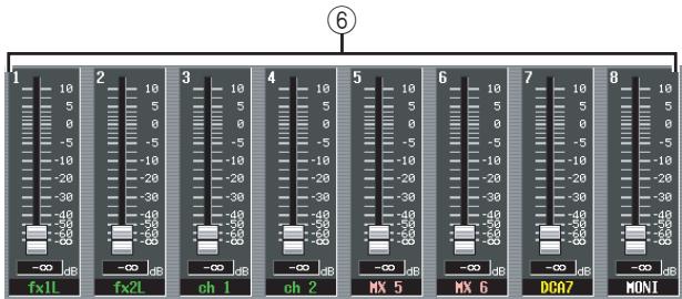
(6) Faders 1-8
The parameter assigned to each fader of the DCA fader section is shown here. This will depend on the currently selected fader mode. You can also operate the fader directly by dragging it upward or downward.
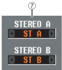
⑦ STEREO A/STEREO B
This selects the function that will be operated by the STEREO faders and STEREO [ON] keys of the STEREO A/B channel strip. You can select ST A/B, MONITOR, or CUE.
Hint
Settings ①-④ and ⑦ will not change until you press the ENTER key to confirm.
SECURITY screen
In this screen you can prohibit console operation (Console Lock), prohibit editing for specific parameters (Parameter Lock) or disabling file loading (Load Lock). Two passwords of differing levels can be specified to allow locking and unlocking.
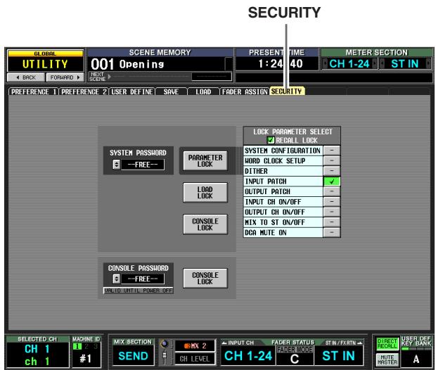
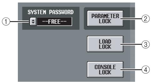
① SYSTEM PASSWORD
This is a permanent password (maximum of eight characters) for the entire system. The password you specify here is valid for the PARAMETER LOCK button (②) and for the CONSOLE LOCK button (④) . However, you can perform the Lock operation even without specifying a password.
If no password has been specified, this box will indicate "--FREE--". If a password has been specified, asterisks (*) will be displayed to represent the characters of the password.
To set or change the password, click the button to open the SYSTEM PASSWORD CHANGE window. When setting the password for the first time, you will input the same password twice for confirmation. To change the password, you will input both the old password and the new password. By specifying a blank entry as the new password, you can restore the state to a condition in which no password has been set.
Note
The system password is remembered even when the power is turned off. This means that if you forget the password, you will be unable to defeat Parameter Lock or Console Lock except by initializing the entire memory of the PM5D ( p.160). Please be careful not to lose the system password.
(2) PARAMETER LOCK
This button sets/defeats Parameter Lock for the parameters selected in the LOCK PARAMETER SELECT area (⑤). If not even one parameter is selected, these buttons will be grayed-out and cannot be turned on. If the system password has been set, clicking this button will open the SYSTEM PASSWORD CHECK window, where you will need to input the system password.
③ LOAD LOCK
This button disables file load operations. If the system password has been set, clicking this button will open the SYSTEM PASSWORD CHECK window, where you will need to input the system password. If this button is on, synchronization with PM5D Editor/DSP5D Editor can occur only from this unit to PM5D Editor/DSP5D Editor (not in the opposite direction).
④ CONSOLE LOCK
This button locks the console operations. If the system password has been set, clicking this button will open the SYSTEM PASSWORD CHECK window, where you will need to input the system password.
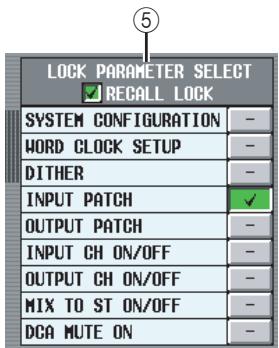
⑤ LOCK PARAMETER SELECT
If the PARAMETER LOCK button (②) is on, parameters for which editing will be disabled can be selected from the following table. As long as the PARAMETER LOCK button (②) is on, these parameters cannot be edited.
| SYSTEM CONFIGU-RATION | Changes to the settings of the MIXER SETUP screen and the CAS-CADE screen |
| WORD CLOCK SETUP | Changes in the word clock setting |
| DITHER | Changes in dither-related settings |
| INPUT PATCH | Changes to the input patch (and NAME) settings |
| OUTPUT PATCH | Changes to the output patch settings |
| INPUT CH ON/OFF | Input channel on/off operations |
| OUTPUT CH ON/OFF | Output channel on/off operations |
| MIX TO ST ON/OFF | MIX channel [TO STEREO] key operations |
| DCA MUTE ON | DCA [MUTE] key On operations (Off operations are not included) |
Note
If you turn on the RECALL LOCK button, the specified parameters will also be unaffected by scene or library recall operations.
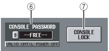
⑥ CONSOLE PASSWORD
This is a temporary password (maximum of eight characters) that is separate from the system password. The password you specify here is valid for the CONSOLE LOCK button (⑦). The method for setting or changing the password is the same as for the system password.
Hint
The Console Password is cleared when the PM5D's power is turned off, and will return to the unset state (the box will indicate "--FREE--").
⑦ CONSOLE LOCK
This button locks the console operations. If the console password has been set, clicking this button will open the CONSOLE PASSWORD CHECK window, where you will need to input the console password.
SYS/W.CLOCK function
WORD CLOCK screen
Here you can select the word clock on which the PM5D will operate. You can also view and edit settings for cards installed in slots 1-4.
WORD CLOCK
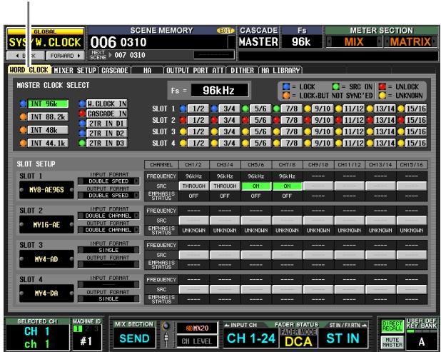
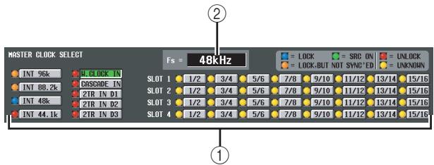
① MASTER CLOCK SELECT
As the master clock to use, you can select the internal clock or an external clock input from a connector or slot. This setting determines the sampling frequency at which the PM5D will operate. You can select the following items.
| Display | Content |
| INT 96k | The PM5D's internal clock (sampling rate= 96 kHz) |
| INT 88.2k | The PM5D's internal clock (sampling rate= 88.2 kHz) |
| INT 48 k | The PM5D's internal clock (sampling rate= 48 kHz) |
| INT 44.1 k | The PM5D's internal clock (sampling rate= 44.1 kHz) |
| W.CLOCK IN | The word clock supplied from the rear panel WORD CLOCK IN connector |
| CASCADE IN | The word clock supplied via the CASCADE IN connector from another cascade-connected PM5D |
| 2TR IN D1 | The clock data of the digital audio signal supplied from 2TR IN DIGITAL connector 1 |
| 2TR IN D2 | The clock data of the digital audio signal supplied from 2TR IN DIGITAL connector 2 |
| 2TR IN D3 | The clock data of the digital audio signal supplied from 2TR IN DIGITAL connector 3 |
| SLOT 1-4 | The clock data of the digital audio signal supplied via a digital I/O card in slot 1-4 (selectable in two-channel units) |
Note
- For the DSP5D, you cannot select 2TR IN D1-D3 or SLOT 3-4. For CASCADE IN, you can choose either the D-sub 68-pin connector or the RJ-45 connector.
- If you make cascade or other connections using the DCU5D's CASCADE OUT (RJ-45) connector, it will not be possible to synchronize to the word clock from the DCU5D's CASCADE OUT (D-sub) connector. In this case, you'll need to provide a separate connection for the word clock.
The operational status of each clock is shown by the color of the symbol at the left of each button. Each color has the following significance.
- LOCK (blue)
This indicates that a clock synchronized with the source selected in (②) is being input. If an external device is connected to the corresponding connector or slot, input/output is occurring normally between that device and the PM5D. If the sampling frequency is close, this status may be displayed even if not synchronized.
- UNLOCK (red)
A valid clock is not being input. If an external device is connected to the corresponding connector, input/output cannot occur correctly between that device and the PM5D.
- LOCK, BUT NOT SYNC'ED (orange)
A valid clock is being input, but is not synchronized with the clock source selected in (②). If an external device is connected to the corresponding connector, input/output cannot occur correctly between that device and the PM5D.
- UNKNOWN (yellow)
This indicates that the clock status cannot be detected because no external device is connected or because there is no valid clock input. You will be able to select this connector/slot, but successful synchronization cannot occur until a valid connection is established.
- SRC ON (green)
This is a special status only for SLOT 1-4 and 2TR IN 2TR IN D1-3, indicating that the corresponding channel's SRC (Sampling Rate Converter) is enabled. This means that even if the signal is not synchronized, normal input/output with the PM5D is occurring.
Note
- Noise may occur at the output jacks when the word clock setting is changed. In order to protect your speaker system, be sure to turn down the power amp output before changing the word clock setting.
- If you attempt to select a channel whose SRC is on as the word clock master, a message will appear, warning you that the sampling rate converter will be disabled.
(2) Fs (Sampling frequency)
This indicates the sampling frequency at which the PM5D is operating. This will indicate "UNLOCKED" while synchronization is lost (such as immediately after switching the master clock).
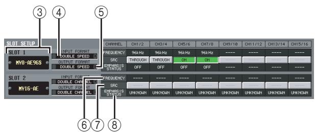
③ Slot number / Card type
This area shows the type of digital I/O card installed in slots 1-4.
④ INPUT FORMAT (Input signal format)
⑤ OUTPUT FORMAT (Output signal format)
Select one of the following as the method by which signals will be exchanged with a digital I/O card installed in the slot when the PM5D is operating at a high sampling rate (88.2/96 kHz).
- SINGLE
This setting allows transmission/reception of the normal number of channels when existing equipment that operates at 44.1 / 48kHz is connected. The sampling rate will be converted for each channel of the digital I/O card, and transmitted/received at half the sampling frequency (44.1 / 48kHz) of the PM5D. (This setting can be selected only for slots in which a digital I/O card that does not support 96kHz is installed.)
- DOUBLE SPEED
This setting allows high sampling rate audio signals to be transmitted/received without change when equipment that operates at a high sampling rate (88.2/96 kHz) is connected. (This setting can be connected only for slots in which a digital I/O card that supports 96 kHz is installed.)
- DOUBLE CHANNEL
This setting allows high sampling rate (88.2/96 kHz) audio signals to be handled when existing equipment that operates at 44.1/48 kHz is connected. Two channels of signals at half the PM5D's sampling frequency (44.1/48 kHz) are transmitted/received together as a high sampling rate monaural signal. (The number of usable channels will be half.)
(6) FREQUENCY (Sampling frequency)
This indicates the sampling frequency of the signal being input to each channel of the digital I/O card, in sets of two channels.
⑦ SRC (Sampling Rate Converter)
This button switches the Sampling Rate Converter on/off, in sets of two channels. This is available only for slots in which a digital I/O card with a built-in sampling rate converter is installed.
⑧ EMPHASIS STATUS
This indicates whether emphasis is applied to the input signal, in sets of two channels. This is available only for slots in which a digital I/O card is installed.
MIXER SETUP screen
Here you can make settings that apply to the entire PM5D system.
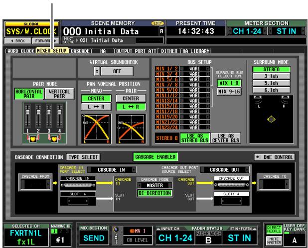
MIXER SETUP
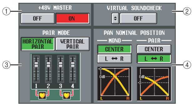
① +48V MASTER (DSP5D only)
This is the master phantom power (+48V) switch for INPUT jacks 1-48 and ST IN jacks 1-4. If this switch is off, the +48V button shown in the display will be disabled.
(2) VIRTUAL SOUNDCHECK
This temporarily switches the input signals without affecting the scene memory (input patching). For example, this allows you to perform a sound check using pre-recorded material played back by a DAW connected to a slot, instead of the analog input material received via the INPUT jacks. When you click the button located at the left, the VIRTUAL SOUND-CHECK SETUP window will appear, allowing you to assign a replacement port for each port. To enable these settings, click the ON/OFF button located at the right.
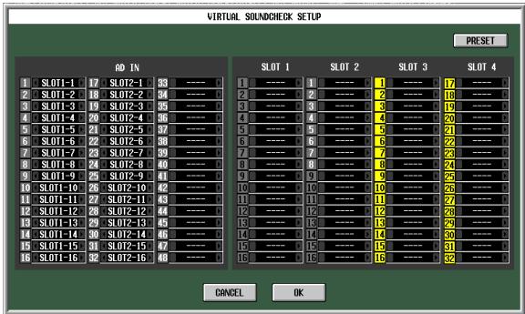
For each port, you can specify a port that will be substituted virtually. You cannot assign the same port to more than one port. If you assign a previously-assigned port to a different port, the patch will be turned off (shown in
gray) for the port whose assignment was taken away. If a slot is exchanged with the CASCADE IN connector, the cascade bus number will be displayed in black on a yellow background in the slot port number display area. In the example shown above, slots 1 and 2 are assigned to AD IN 1-32, so you'll be able to perform a sound check using pre-recorded audio received at slots 1 and 2 instead of the analog inputs to the INPUT jacks.
By clicking the PRESET button, you can return the settings of the VIRTUAL SOUNDCHECK SETUP window to their factory-set state.
(3) PAIR MODE
Select one of the following two methods by which input channels will be paired.
HORIZONTAL PAIR
If this button is on, input channels of adjacent numbers (1/2, 3/4 ...) will be paired.
- VERTICAL PAIR
If this button is on, input channels of different layers that share the same fader (1/25, 2/26 ...) will be paired. This setting lets you use the faders of the INPUT channel strip to control up to 24 pairs (48 channels).
Hint
The graphic below the buttons will change according to the pair mode you select.
When you switch from horizontal pair mode to vertical pair mode, new numbers will be assigned to the input channels as follows.
Channel 1 no change
Channel 2 Channel 25
Channel 3 Channel 2
Channel 4 Channel 26
:
Channel 47 Channel 24
Channel 48 no change
(If you again switch back to horizontal pair mode, the channels will return to their previous number.) However, please note that this simply means the input channel that was previously called "channel 2" is now called "channel 25"; the name and parameter settings of that channel have not changed.
In the various screens of the display (except for the TRACKING RECALL screen and the FADER VIEW screen), switching the pair mode will only change the displayed numbers; the arrangement of the input channels will not change.
(4) PAN NOMINAL POSITION
Here you can specify whether a signal will be at nominal level when panned to center, or at nominal level when panned far left or far right. Choose one of the following two settings. You can choose independently for monaural channels and paired channels.
- CENTER
The signal will be at nominal level (+0dB) when panned to the center, and will rise +3dB when panned to far left or far right.
L R
The signal will be at nominal level (+0dB) when panned to far left or far right, and will decrease -3dB when panned to the center.
Hint
The current setting is also shown by the graph below the buttons.
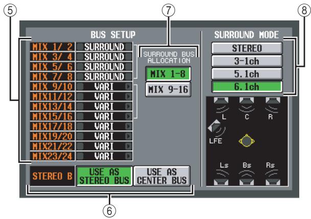
⑤ BUS SETUP
This area indicates the MIX bus mode (VARI/FIXED) for every two adjacent odd-numbered/even-numbered MIX buses. You can edit the setting by clicking the 4 / 5 buttons at the left and right.
⑥ STEREOB
Select one of the following two choices to specify how the STEREO B bus will function.
USE AS STEREO BUS
If this button is on, the STEREO B bus will function as a conventional stereo bus; the same signal as the STE-REO A bus will be sent to it.
USEASCENTERBUS
If this button is on, the STEREO B bus will function as the CENTER bus of LCR mode. When you turn this on, the CENTER bus output signal will be added to the L/R channels of the STEREO A bus, allowing LCR playback (three-channel playback). (The monitor signal will also be played back from the three MONITOR OUT connectors L/C/R.
Note
If the USE AS STEREO BUS button is on, LCR mode is disabled.
Choose which of the following two ranges of MIX bus will be used as surround buses.
MIX 1-8 .......MIX bus 1-8
MIX 9-16 . . . MIX bus 9-16
⑧ SURROUND MODE
Choose one of the following as the surround mode when using the Surround Pan function ( p.142).
STEREO
This is conventional stereo mode.
3-1ch
This mode uses four channels: L (front left), C (front center), R (front right), and S (surround).
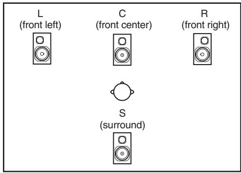
5.1ch
This mode uses six channels: L (front left), C (front center), R (front right), Ls (rear left), Rs (rear right), and LFE (subwoofer).
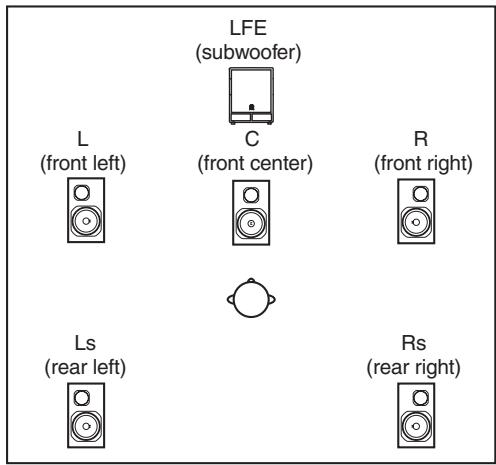
6.1ch
This mode uses seven channels: 5.1ch with the addition of Bs (rear center).
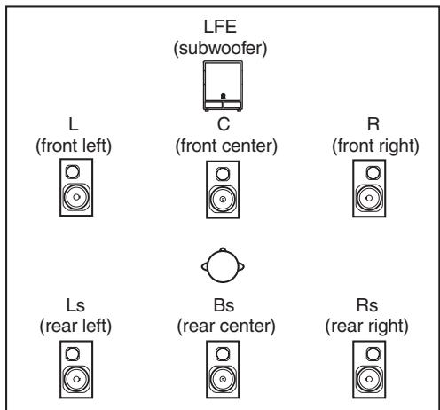
Hint
The graphic below the buttons will change according to the mode you select.
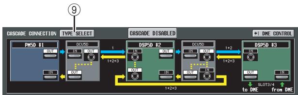
(9) TYPE SELECT
Click this window to access the CASCADE TYPE SELECT window, where you can select the type of cascade connection.
Note
- Set the cascade connection type to match the actual connection. If it does not match, the system will not operate correctly.
- The head margin of the buses that can be cascaded may change according to the type of cascade connection.
In the CASCADE CONNECTION area of the MIXER SETUP screen, the color of the route (heavy arrow) between machines indicate the type or status of the route as follows.
Blue: A route that sums the buses of each machine
Yellow: A route that returns the final signal of the cascaded buses
Red: A route that is not connected correctly
Gray: A route for which it cannot be determined whether the connection is correct
This means that in order for the cascade connection to work properly, you must make connections and settings so that no routes are displayed in red or gray. The numbers shown above or below each route indicate the number of each machine included in the signals that flow through each route.
PM5D-PM5D
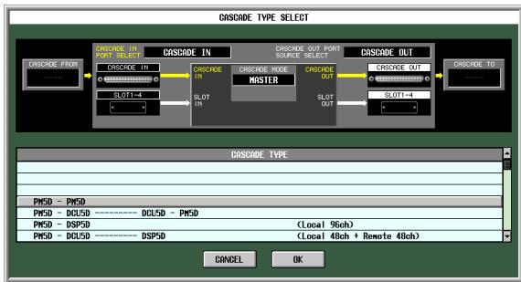
This system directly cascade-connects PM5D units. A maximum of four PM5D units can be connected. Use ⑫-⑰ to specify the details of the cascade connection.
PM5D-DCU5D-DCU5D-PM5D
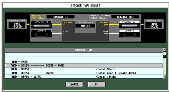
This system cascade-connects two DCU5D units between the PM5D units in order to extend the dis
tance of the cascade connection. A maximum of two PM5D units can be connected. Use ⑫-⑰ to specify the details of the cascade connection.
PM5D-DSP5D
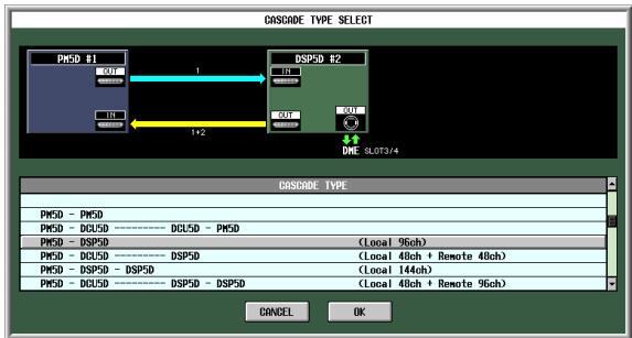
This system cascade-connects one DSP5D unit to the PM5D, expanding the number of input channels to 96 monaural input channels.
PM5D-DCU5D—DSP5D
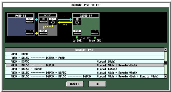
This system cascade-connects one DCU5D and one DSP5D to the PM5D, adding 48 remotely located monaural inputs.
PM5D-DSP5D-DSP5D
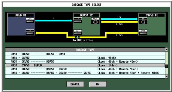
This system cascade-connects two DSP5D units to the PM5D, expanding the number of input channels to 144 monaural input channels.
PM5D-DCU5D—DSP5D-DSP5D
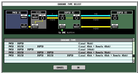
This system cascade-connects one DCU5D and two DSP5D units to the PM5D, adding 96 remotely located monaural inputs.
PM5D-DCU5D—DSP5D-DCU5D—DSP5D
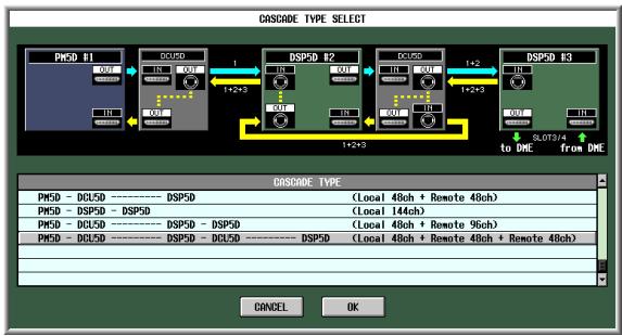
This system cascade-connects two DCU5D units and two DSP5D units to the PM5D, adding two sets of 48 remotely located monaural inputs.
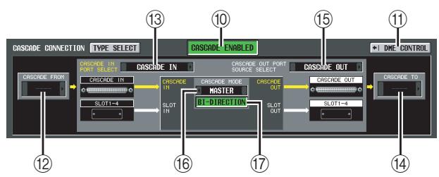
10 CASCADE ENABLED/DISABLED
Turns the Cascade function on/off.
Note
- If you edit the parameters (⑨ - ⑰) included in CASCADE CONNECTION or power-cycle the unit, the cascade function will return to the Off state.
- If word clock becomes unlocked while machines are synchronized (before cascade connection is enabled), the operation of each machine may become unstable. If this occurs, please power-cycle each machine.
- This setting will not be loaded for PM5D firmware V2.0 and later.
11 DME CONTROL
This button accesses the DME CONTROL screen ( p.199).
The following items (12)–(17) are shown only if you select “PM5D-PM5D” or “PM5D-DCU5D — DCU5D-PM5D” as the cascade-connection type. If you select a cascade-connection that includes a DSP5D, the same settings are made automatically, and the settings will be only for viewing.
⑫ CASCADE FROM (Source when cascadeconnected)
Select one of the following as the external device that is sending audio signals to the PM5D via a cascade connection.
| Display | Source device | Available cas-cade input port | Parame-ter linkage |
| — | Cascade disabled | CASCADE IN, SLOT 3/4, SLOT 1-4 [CH1-8], SLOT 1-4 [CH9-16] | Not possible |
| PM5D or PM5D+ DCU5D | another PM5D | CASCADE IN | Possible *1 |
| Display | Source device | Available cas-cade input port | Parame-ter linkage |
| DM2000/02R96 | Yamaha DM2000 or 02R96 | CASCADE IN | Not possible |
| MIXER [30BUS] | A mixer other than the above (maxi-mum 30 bus) | SLOT 3/4,SLOT 1-4[CH1-8],SLOT 1-4 [CH9-16] | |
| MIXER [16BUS] | A mixer other than the above (maxi-mum 16 bus) | SLOT 4 |
*1. Linked parameters are specified in the CASCADE screen.
13 CASCADE IN PORT SELECT
Select one of the following as the port that will receive the audio signals from the cascade-connected device.
Hint
- If you select a choice other than CASCADE IN, the signal from the slot will be assigned to the cascade input, and the signal from the CASCADE IN connector will be assigned to the corresponding slot input.
-
The signal assigned from the CASCADE IN connector to the slot input can be used as a patch source in the IN PATCH screen.
-
CASCADE IN
Up to 30 channels of audio signals can be received from another PM5D via the rear panel CASCADE IN connector. If PM5D is selected as the cascade source (12), control signals for parameter linkage will also be transmitted and received.
- SLOT 4
Up to 16 channels of audio signals can be received via input channels 1-16 of an I/O card installed in slot 4 of the rear panel. If you choose this setting, the signals from the CASCADE IN connector (channels 1-16) will be assigned to channels 1-16 of the SLOT IN 4 port instead.
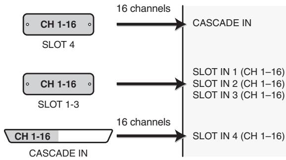
- SLOT 3/4
Up to 30 channels of audio signals can be received via input channels 1-16 of I/O cards installed in slots 3 and 4. (Since channels 15/16 of SLOT 4 are not used, only 30 channels are actually available.) If you choose this setting, the signals from the CASCADE IN connector (channels 1-32) will be assigned to channels 1-16 of the SLOT IN 3/4 ports instead.
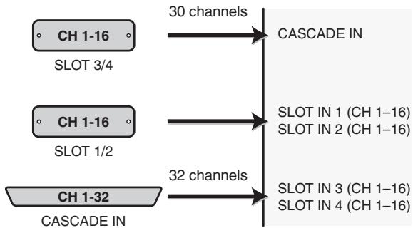
- SLOT 1-4 [CH1-8]
Up to 30 channels of audio signals can be received via input channels 1-8 of I/O cards installed in slots 1-4. (Since channels 7/8 of SLOT 4 are not used, only 30 channels are actually available.) If you choose this setting, the signals from the CASCADE IN connector (channels 1-32) will be assigned to channels 1-8 of the SLOT IN 1-4 ports instead.
![YAMAHA PM5D-RH - - SLOT 1-4 [CH1-8] - 1](/content/2025/01/115055/images/7c37f27225d96ef6c59f28764661deead843bb59ef25075fafb0b1c461c6ffbe.jpg)
- SLOT 1-4 [CH9-16]
Up to 30 channels of audio signals can be received via input channels 9-16 of I/O cards installed in slots 1-4. (Since channels 15/16 of SLOT 4 are not used, only 30 channels are actually available.) If you choose this setting, the signals from the CASCADE IN connector (channels 1-32) will be assigned to channels 9-16 of the SLOT IN 1-4 ports instead.
![YAMAHA PM5D-RH - - SLOT 1-4 [CH9-16] - 1](/content/2025/01/115055/images/bc02df50b969a95355f7b816941705b2669845447581d352e98a0d55fd1a50ac.jpg)
14 CASCADE TO (Transmission destination when cascade-connected)
As the external device to which audio signals will be transmitted and control signals exchanged over the cascade connection, you can select either PM5D/PM5D+DCU5D (i.e., a different PM5D unit) or "----" (transmission disabled).
15 CASCADE OUT PORT SOURCE SELECT
Select one of the following as the signal source that will be output from the CASCADE OUT connector.
Hint
If you select a setting other than CASCADE OUT, the same signals will be output both to the corresponding slots and to the CASCADE OUT connector.
- CASCADE OUT
The audio signals sent by the cascade function will be output from the CASCADE OUT connector. If PM5D is selected as the transmission destination (14) , control signals for parameter linkage will also be transmitted and received. The type of signals that are output can be selected in the CASCADE screen.
- SLOT 3/4
The same audio signals (up to 32 channels) as are output from output channels 1-16 of slots 3/4 will be output in parallel from the CASCADE OUT connector.
- SLOT 1-4 [CH1-8]
The same audio signals (up to 32 channels) that are output from output channels 1-8 of slots 1-4 will also be output in parallel from the CASCADE OUT connector.
- SLOT 1-4 [CH9-16]
The same audio signals (up to 32 channels) that are output from output channels 9-16 of slots 1-4 will also be output in parallel from the CASCADE OUT connector.
16 CASCADE MODE
Choose one of the following two modes of operation when multiple PM5D units are cascade-connected.
- MASTER
If the Cascade function is enabled, control signals will be sent to an external PM5D.
SLAVE
If the Cascade function is enabled, control signals will be received from an external PM5D.
⑦ BI-DIRECTION (Bi-directional communication)
When multiple PM5D units are connected, this button selects whether they will mix each other's audio signals. Set the Cascade mode and the BI-DIRECTION button according to the type of cascade connection, as discussed below.
If you cascade-connect two PM5D units in a "ring" topology (i.e., connect the CASCADE IN connector of each unit to the OUT connector of the other unit), set the cascade mode to MASTER on one unit and SLAVE on the other unit. Turn the BI-DIRECTION button On for both units.
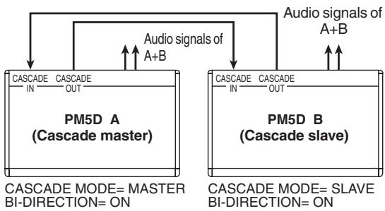
In this state, the SLAVE unit will follow when you operate the MASTER unit. The same mix will be output from both PM5D units.
If you daisy-chain two to four PM5D units (i.e., connect the first unit's CASCADE OUT second unit's CASCADE IN, and the second unit's CASCADE OUT third unit's CASCADE IN. Up to four units can be connected.), set the PM5D located last in the chain to MASTER, and the remaining PM5D units to SLAVE. Turn the BI-DIRECTION button Off for all units.
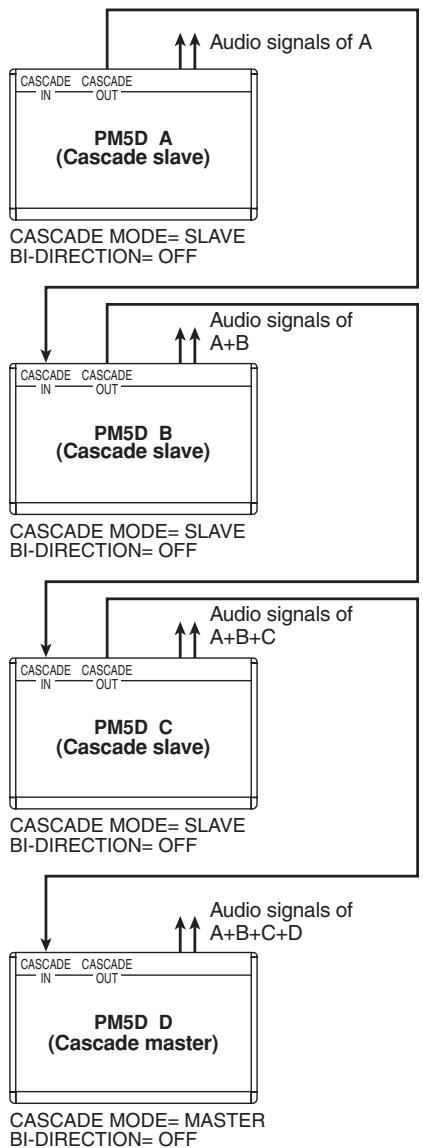
In this state, the SLAVE units will follow when you operate the MASTER unit. The final mix of all signals will be output from the PM5D that is connected last in the chain.
CASCADE screen
Here you can make various settings related to cascade connection.
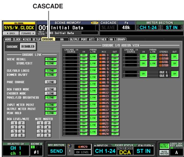
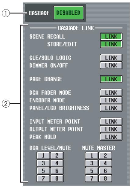
① CASCADE ENABLED/DISABLED
Enables/disables cascade connection.
② CASCADE LINK
Here you can select the operations and parameters that will be linked when multiple PM5D units are cascade-connected. You can select the following items.
SCENE RECALL
Scene recall operations / Recall undo operations
- SCENE STORE/EDIT
Scene store operations, store undo operations, title editing, sorting
- CUE/SOLO LOGIC
Cue/Solo operations (however, all Cue settings are cleared when linking occurs)
- DIMMER ON/OFF
Dimmer effect (including talkback dimmer)
PAGE CHANGE
Switching the display screen
DCA FADER MODE
Switching the mode of the top panel FADER MODE section
- ENCODER MODE
Switching the mode of the top panel ENCODER MODE section
- PANEL/LCD BRIGHTNESS
BRIGHTNESS settings in the PREFERENCE 2 screen (UTILITY function)
- INPUT METER POINT/OUTPUT METER POINT/ PEAK HOLD
Input channel / output channel metering point selection, and peak hold on/off
DCA LEVEL/MUTE
DCA group 1-8 level, name, [CUE] key on/off operations, and [MUTE] key on/off operations
Hint
DCA and MUTE parameter values will be linked the instant Link is turned on. Other parameters will be linked for the first time only when that parameter is operated after Link is turned on.
MUTE MASTER
Mute group 1-8 on/off
Hint
- For details on the actual procedure of cascade-connecting multiple PM5D/DSP5D units, refer to p.153.
- In the case of a system that is cascade-connected to the DSP5D, the system will always operate as though the CASCADE LINK area's LINK button is on; this setting cannot be changed. Other operations may also be linked.
- To enable cascade link, you must turn on linking for the corresponding parameters on the other cascade-connected PM5D units as well.
- You can also turn linking off for the master PM5D. For example if you've cascade-connected multiple PM5D units, you can (for example) make settings so that DCA 1 is linked only between the master and the second unit, DCA 2 is linked for all PM5D units, and DCA 3 is linked only between the second unit and third unit.
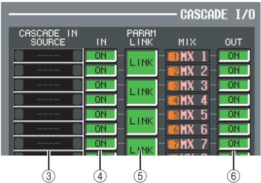
③ CASCADE IN SOURCE (Cascade IN source I/O assignment view)
Here you can view and select the signals that are sent to the PM5D/DSP5D's internal buses from the cascade-connected external device. The type of signals received will depend on the selection in the CASCADE FROM field of the MIXER SETUP screen (SYS/W.CLOCK function.)
| External device selected in the CASCADE FROM field | Destina-tion bus | |||
| PM5D/DSP5D*1 | DM2000/02R96*1 | MIXER[30BUS] | MIXER[16BUS]*2 | |
| MIX 1 | BUS 1 | *3 | SLOT4-1 | MIX 1 |
| MIX 2 | BUS 2 | SLOT4-2 | MIX 2 | |
| MIX 3 | BUS 3 | SLOT4-3 | MIX 3 | |
| MIX 4 | BUS 4 | SLOT4-4 | MIX 4 | |
| MIX 5 | BUS 5 | SLOT4-5 | MIX 5 | |
| MIX 6 | BUS 6 | SLOT4-6 | MIX 6 | |
| MIX 7 | BUS 7 | SLOT4-7 | MIX 7 | |
| MIX 8 | BUS 8 | SLOT4-8 | MIX 8 | |
| MIX 9 | AUX 1 | SLOT4-9 | MIX 9 | |
| MIX10 | AUX 2 | SLOT4-10 | MIX10 | |
| MIX11 | AUX 3 | SLOT4-11 | MIX11 | |
| MIX12 | AUX 4 | SLOT4-12 | MIX12 | |
| MIX13 | AUX 5 | SLOT4-1 | MIX13 | |
| MIX14 | AUX 6 | SLOT4-2 | MIX14 | |
| MIX15 | AUX 7 | SLOT4-3 | MIX15 | |
| MIX16 | AUX 8 | SLOT4-4 | MIX16 | |
| MIX17 | AUX 9 | SLOT4-5 | MIX17 | |
| MIX18 | AUX10 | SLOT4-6 | MIX18 | |
| MIX19 | AUX11 | SLOT4-7 | MIX19 | |
| MIX20 | AUX12 | SLOT4-8 | MIX20 | |
| MIX21 | — | SLOT4-9 | MIX21 | |
| MIX22 | — | SLOT4-10 | MIX22 | |
| MIX23 | — | SLOT4-11 | MIX23 | |
| MIX24 | — | SLOT4-12 | MIX24 | |
| ST AL | ST L | SLOT4-13 | ST AL | |
| ST AR | ST R | SLOT4-14 | ST AR | |
| ST BL | — | SLOT4-9 | ST BL | |
| ST BR | — | SLOT4-10 | ST BR | |
| CUE L | CUE L | SLOT4-15 | CUE L | |
| CUE R | CUE R | SLOT4-16 | CUE R | |
1. The signal assigned to each bus is fixed; it cannot be changed.
2. You can enable/disable the assignment for each bus. However, you cannot send the signal of the same slot or same input channel to multiple buses. If a signal already assigned to a bus is selected for a different bus, the previous assignment will be cancelled.
*3. Assigned from the top in ascending numerical order of slot number / channel number, according to the settings of the CASCADE IN PORT SELECT area of the MIXER SETUP screen (SYS/W.CLOCK function). (this cannot be changed.)
④ CASCADE IN ON/OFF
For each of the PM5D/DSP5D's internal buses, you can specify whether signals from the cascade master will be input.
(5) PARAM LINK (parameter link)
For each pair of adjacent odd-numbered/even-numbered channels, this specifies whether the PM5D/ DSP5D's channel parameters will be linked to output the identical signal.
⑥ CASCADE OUT ON/OFF
For each of the PM5D/DSP5D's internal buses, you can specify whether signals will be output to the cascade slave.
HA (Head Amp) screen
In this screen you can make settings such as phantom power (+48V) , gain, and HPF for each of the internal head amps (PM5D-RH model and DSP5D only), or for each channel of an external head amp device that supports remote control via the dedicated protocol (e.g., Yamaha AD8HR or AD824).
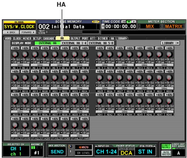
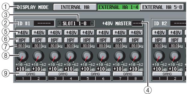
① DISPLAY MODE
Select one of the following as the type of head amp displayed in the screen.
- INTERNAL HA (PM5D-RH/DSP5D)
The internal head amp channels (AD IN 1-48, AD STIN 1-4) will be displayed. - EXTERNAL HA 1-4
- EXTERNAL HA 5-8
The channels of an external head amp device (ID number = 1 - 4 or ID number = 5 - 8 ) connected via the [HA REMOTE] connector will be displayed.
Hint
Up to eight external devices can be daisy-chained to the PM5D's [HA REMOTE] connector. In this case, an ID number (1-8) is automatically assigned to each device, starting from the device that is connected directly to the PM5D's [HA REMOTE] connector.
(2) Model name
For each ID number, this indicates the model name of the external head amp device that is connected. If no device is connected this will indicate "-----". However even in this case, you will be able to make the same settings as when a Yamaha AD8HR is connected.
③ Slot/Channel
Here you can view/select the slot and channels to which the audio output of the external head amp device is connected.
Note
If an external head amp device is connected to a PM5D slot, you must specify the appropriate slot/channels manually. Please note that if you specify an incorrect setting, the input channel HA indication in screens such as the IN HA screen may differ from the actual state.
(4) +48V MASTER
If an AD8HR is connected via the [HA REMOTE] connector, this indicates the master phantom power on/off status. (Otherwise, this indicates "---".)
(5) +48V
Switches phantom power (+48V) on/off for each channel.
HPF (High Pass Filter)
Turns the HPF on/off for each channel.
Cutoff frequency
Specifies the HPF cutoff frequency for each channel of the AD8HR. Move the cursor to the box, and turn the [DATA] encoder to adjust the cutoff frequency in a range of 20 - 600Hz
⑧ GAIN
Adjusts the gain for each channel. Move the cursor to the knob, and turn the [DATA] encoder to adjust the gain in a range of -62dB to +10dB . The current value is shown in the box below.
Note
The PAD will be switched on or off internally when the gain of the PM5D-RH internal head amp is adjusted between -14dB and -13dB . Keep in mind that noise may be generated if there is a difference between the Hot and Cold output impedance of the external device connected to the INPUT connector/ST IN connector when using phantom power.
GANG
If this button is on, the gain settings of two adjacent odd-numbered/even-numbered channels will change in tandem, maintaining the current offset value.
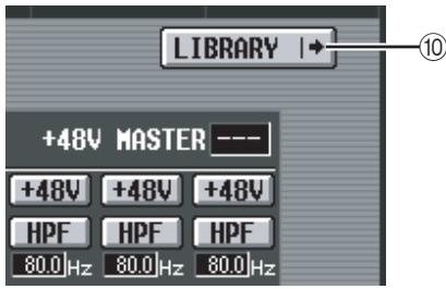
10 LIBRARY
This button displays the HA LIBRARY screen ( p.230).
Note
When an external head amp device is connected for the first time, the settings on the external head amp device are used. If you subsequently recall a HA library item, the HA library settings are used.
OUTPUT PORT ATT (Output port attenuation) screen
In this screen you can specify the amount of attenuation for each output channel and for each output channel of an I/O card.
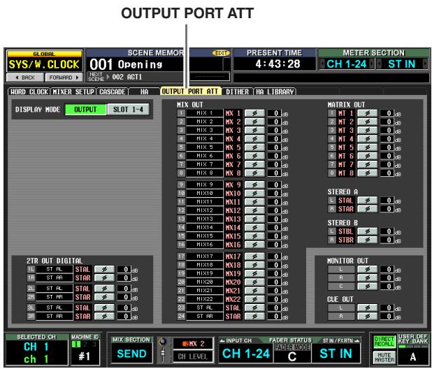
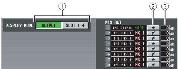
① DISPLAY MODE
Select the channels that will appear in the display, from the following choices.
OUTPUT
The screen will show the amount of attenuation for output channels (MIX channels 1-24, MATRIX channels 1-8, STEREO A L/R channels, STEREO B L/R channels), CUE L/R channels, MONITOR L/R/C channels, and 2TR OUT DIGITAL 1-3 L/R channels.
SLOT 1-4
The screen will show the amount of attenuation for each output channel of the I/O cards installed in slots 1-4.
② 0 (phase)
If this button is on, the phase of the output port will be reversed.
③ ATT (Attenuation)
Adjusts the amount of attenuation for each channel. Move the cursor to the box, and turn the [DATA] encoder to adjust the value in a range of -9 to 0dB
DITHER screen
In this screen you can turn dithering on/off and specify the bit depth for dithering. These settings are made individually for each digital output jack and each output channel of the digital I/O cards.
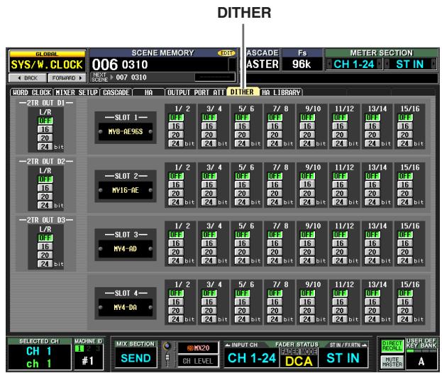
① Digital output jack dither settings
Specify the number of bits (16, 20, 24 bits) used when dithering the output signals from 2TR DIGITAL OUT jacks 1-3. If you select OFF, dithering will not be performed.
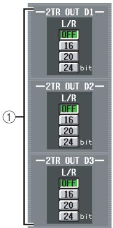
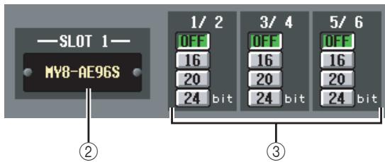
② Slots 1-4
This area shows the type of digital I/O card installed in each slot.
③ Digital I/O card dither settings
For each output channel of the digital I/O cards installed in the slots, specify the number of bits used when dithering.
HA LIBRARY screen
In this screen you can recall, store, rename, or delete items in the HA library.
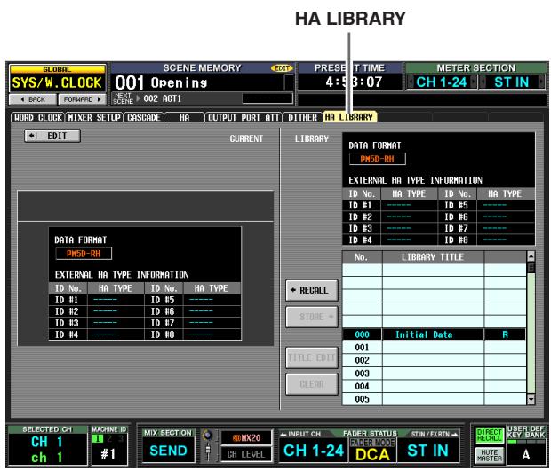
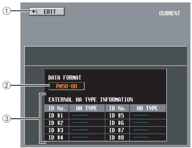
① EDIT
When you click this button, the HA screen will appear.
(2) DATA FORMAT
Indicates the model name (PM5D or PM5D-RH).
Note
In the case of the DSP5D, it will be indicated as "PM5D-RH."
(3) EXTERNAL HA TYPE INFORMATION
This area shows the model names (AD8HR/AD824) of the external head amp devices (ID numbers = 1 - 8 connected to the PM5D's [HA REMOTE] connector.
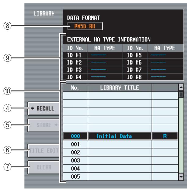
(4) RECALL
Recalls the HA library item selected in the list into memory.
⑤ STORE
Stores the current settings of the HA screen into the location selected in the list. When you click this button a window will appear, allowing you to name and save the settings.
(6) TITLE EDIT
Edits the title of the library item selected in the list. When you click this button a window will appear, allowing you to edit the title.
(7) CLEAR
Deletes the library item selected in the list. When you click this button, a confirmation message will appear.
Note
Library items with an "R" displayed in the right column of the list are read-only. Read-only items cannot be stored, renamed, or deleted.
(8) DATA FORMAT
Indicates the data format (PM5D-RH or PM5D) of the library item selected in the list.
Note
Data stored by the DSP5D will be indicated as "PM5D-RH."
(9) EXTERNAL HA TYPE INFORMATION
This area indicates the model name (AD8HR/AD824) of the external head amps (ID numbers = 1 - 8 ) for which data is stored in the library.
Note
If a DSP5D (machine #2 or #3) is selected as the target of control, this information will not be displayed.
⑩ Library list
Use the scroll bar to select the library item on which you want to perform an operation. The selected library item will move to the center, and will be highlighted.
Note
-
If PM5D format data is recalled to the PM5D-RH, the internal head amp settings will not change. If PM5D-RH format data is recalled to the PM5D, the internal head amp settings will be ignored.
-
If the recall-source and recall-destination head amp devices have the same ID number but are assigned to different slots/ channels, the data will not be recalled to head amps of those ID numbers.
- AD8HR data can be recalled into an AD824, and AD824 data can be recalled into an AD8HR. However when AD8HR data is recalled to an AD824, the gain settings of each channel will be converted into 6 dB units in order to match the specifications of the AD824.
METER function
INPUT METER screen
This screen contains meters that show the input level of the input channels (input channels 1-48, ST IN channels 1-4, FXTRN channels 1-4).
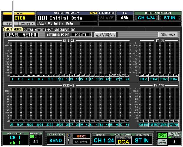
INPUT METER
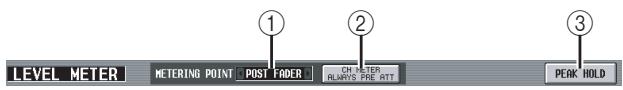
① METERING POINT
Select one of the following as the point at which the input level will be detected. This setting also applies to the meters on the panel.
PRE ATT . . . . . . Immediately before the attenuator
PRE GATE ....... Immediately before the internal gate
PRE FADER . . . . Immediately before the fader
POST FADER....... Immediately after the fader
POST ON . . . Immediately after the [ON] key
CH METER ALWAYS PRE ATT
If this button is on, the input channel meters of the panel will always show the pre-attenuator levels.
(3) PEAK HOLD
If this button is on, the peak level of each meter will be held. When you turn this button off, the peak level indication that had been held will be cleared. Peak hold will be cleared when you change the metering point
(1). This button is linked with the [PEAK HOLD] key in the METER section of the top panel.
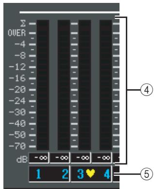
④ Meters
These peak level meters indicate the input level of each channel. The current fader value is shown in the box below.
If clipping occurs at any point PRE ATT, POST EQ, POST GATE, POST COMP, INSERT IN, or POST FADER, the segment will light.
(5) Pair icon
This indicates the pairing status of two adjacent odd-numbered/even-numbered channels.
OUTPUT METER screen
This screen contains meters that show the output level of output channels (MIX channels 1-24, MATRIX channels 1-8, STEREO A/B channels), MONITOR (L/R/C), and CUE (L/R).
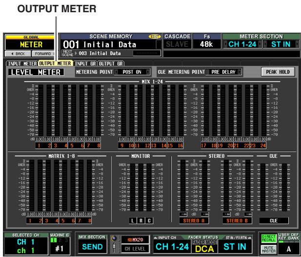

(1) METERING POINT
Select one of the following as the point at which the output level will be detected.
PRE EQ . Immediately before the EQ
PRE FADER . . . . Immediately before the fader
POST FADER....... Immediately after the fader
POST ON . . . Immediately after the [ON] key
POST DELAY ....... Immediately after the internal delay (of an output channel)
(2) CUE METERING POINT
Select one of the following as the point at which the output level of the cue signal will be detected.
PRE DELAY ....... Immediately before the internal delay (of a monitor/cue channel)
POST DELAY ....... Immediately after the internal delay (of a monitor/cue channel)
(3) PEAK HOLD
If this button is on, the peak level of each meter will be held. When you turn this button off, the peak level indication that had been held will be cleared. Peak hold will be cleared when you change the metering point
(1). This button is linked with the [PEAK HOLD] key in the METER section of the top panel.
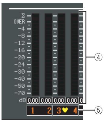
④ Meters
These peak level meters indicate the output level of each channel. The current master level value is shown in the box below.
If clipping occurs at any point POST EQ, POST COMP, POST ON, POST FADER, or INSERT IN, the segment will light.
⑤ Pair icon
This indicates the pairing status of two adjacent odd-numbered/even-numbered channels.
INPUT GR (Input Gain Reduction) screen
This screen contains meters that show the amount of gain reduction produced by the gate/compressor for each input channel (input channels 1-48, ST IN channels 1-4).
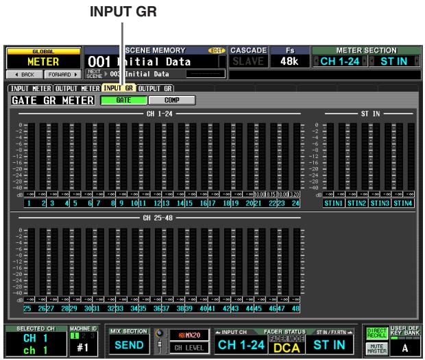

① GATE/COMP (Gate / Compressor)
These buttons select either Gate or Compressor as the processor whose gain reduction amount is shown by the meters. The display at the left will change according to your selection.
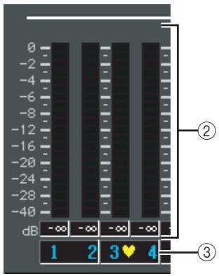
② Meters
These peak level meters indicate the amount of gain reduction for each channel. The current fader value is shown in the box below.
③ Pair icon
This indicates the pairing status of two adjacent odd-numbered/even-numbered channels.
OUTPUT GR (Output Gain Reduction) screen
This screen contains meters that show the amount of gain reduction produced by the compressor for each output channel (MIX channels 1-24, MATRIX channels 1-8, STE-REO A/B channels).
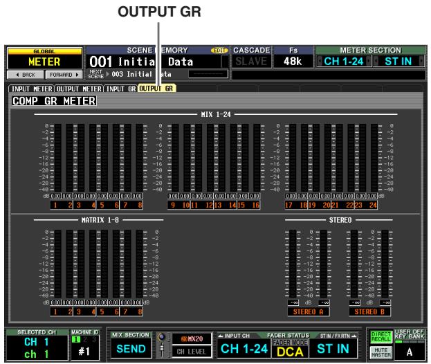
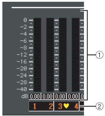
① Meters
These peak level meters indicate the amount of gain reduction for each channel. The current master level value is shown in the box below.
② Pairicon
This indicates the pairing status of two adjacent odd-numbered/even-numbered channels.
MON/CUE function
TALKBACK screen
In this screen you can switch talkback on/off, and select the talkback destination.
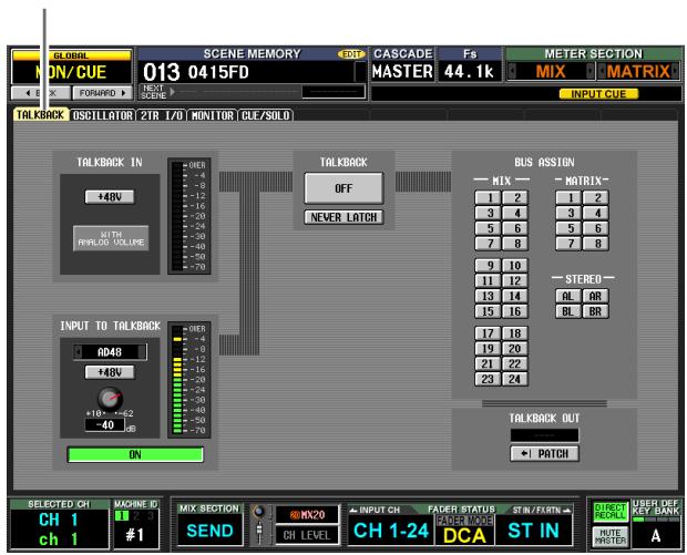
TALKBACK
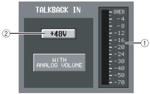
① Level meter (TALKBACK jack level meter)
This level meter indicates the peak level of the signal being input from the TALKBACK jack of the top panel.
(2) +48V (TALKBACK jack phantom power)
This button switches phantom power on/off for the TALKBACK jack.
Note
- The WITH ANALOG VOLUME icon below the button indicates that the LEVEL volume in the TALKBACK section of the panel will affect only the signal being input from the TALKBACK jack.
- If the DSP5D is selected, the TALKBACK IN field is not displayed.
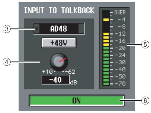
③ Talkback input selection
If you want to use an input jack other than the TALK-BACK jack for purposes of talkback, you can choose it here from analog inputs AD IN 1-48. The talkback input selection is not included in the input patch library.
④ HA (PM5D-RH model only)
Here you can switch phantom power on/off and adjust the gain for the analog input selected in (③). The LEVEL volume in the TALKBACK section of the panel does not affect the talkback input from the analog input channel. The HA setting is included in the HA library.
⑤ Level meter (Analog input level meter)
This level meter indicates the peak level of the signal being input from the analog input selected in (③).
⑥ ON/OFF (Analog input on/off)
This button switches the talkback input selected in (③) on/off.

⑦ ON/OFF (Talkback on/off)
This button switches Talkback on/off. This is linked with the TALKBACK [ON] key in the TALKBACK section of the panel.
NEVER LATCH
This button selects one of the following as the mode in which the TALKBACK ON/OFF button and the panel TALKBACK [ON] key will behave.
- If the NEVER LATCH button is off
Talkback will be switched on/off (Latched operation) each time you click the ON/OFF button or press the TALKBACK [ON] key. However if you press and hold down the TALKBACK [ON] key, talkback will stay on only while you continue holding down the key; talkback will turn off when you release the key (Unlatched operation).
- If the NEVER LATCH button is on
Talkback will be on only while you click and hold down the ON/OFF button or press and hold down the TALKBACK [ON] button; talkback will turn off when you release the button or key (Unlatched operation).
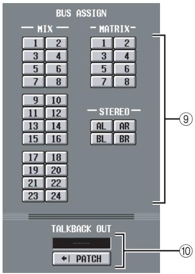
⑨ BUS ASSIGN
Here you can select the bus(es) or output jack(s) from which the talkback signal will be sent. (Multiple selections are allowed.)
MIX 1-24 . . . . . . . . . . . . . . . . . . . . . . . . . . . . . . . . . . . . . . . . . . . . . . . . . . . . . . . . . . . . . . . . . MIX bus 1-24
MATRIX 1-8 .... MATRiX bus 1-8
STAL/R .STEREO A bus L/R channels
STBL/R .STEREO B bus L/R channels
10 TALKBACK OUT (Talkback direct output)
This indicates the channel of the output jack / slot that is selected as the output destination for direct output of the talkback signal. If more than one output destination is patched, "... will be displayed following the name of the output destination that was found first. If you want to change the output destination, click the PATCH button to access the OUTPUT PATCH screen.
OSCILLATOR screen
'Here you can make settings and perform operations related to the internal oscillator.
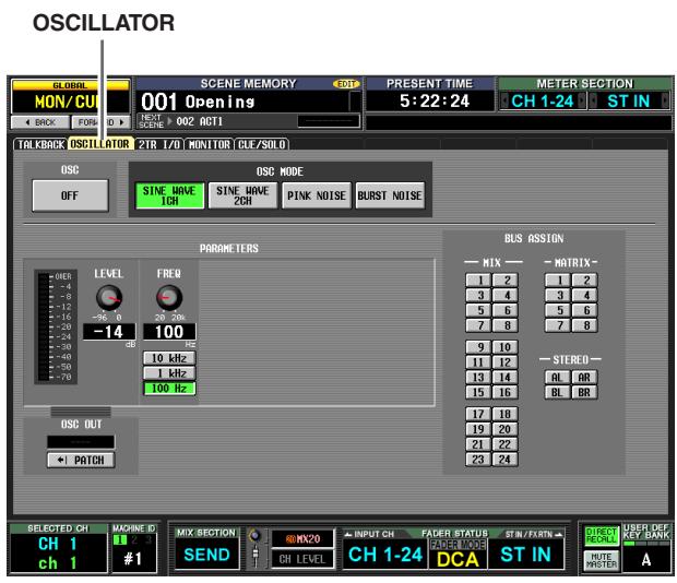
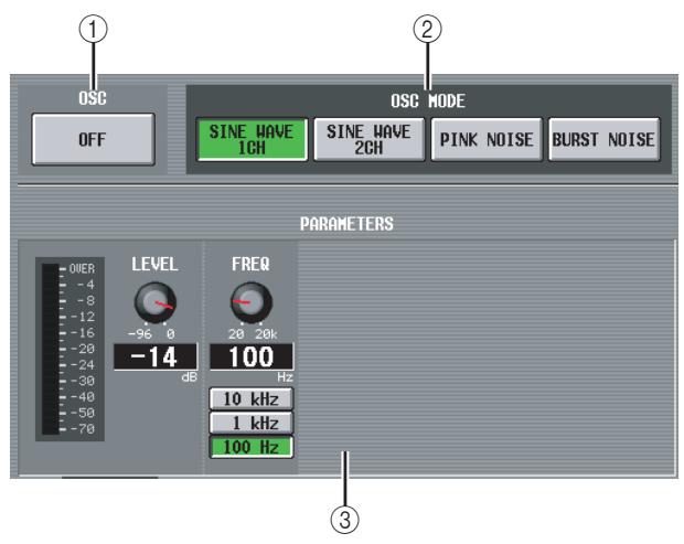
① OSC ON/OFF (Oscillator on/off)
Turns the Oscillator on/off. This is linked with the OSCILLATOR [ON] switch of the top panel.
② OSC MODE (Oscillator mode)
These buttons select the waveform or type of noise produced by the oscillator.
SINE WAVE 1CH. Sine wave x 1 channel
SINE WAVE 2CH. Sine wave x 2 channels
PINK NOISE . . . Pink noise
BURST NOISE . . . . Burst noise (repeated output of pink noise)
(3) PARAMETERS
Here you can set various items according to the selection in (②).
- If SINE WAVE 1CH is selected
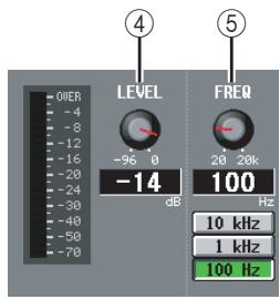
- If SINE WAVE 2CH is selected
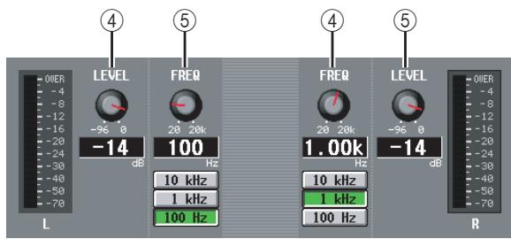
- If PINK NOISE is selected
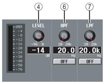
- If BURST NOISE is selected
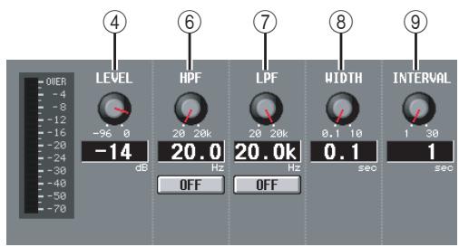
(4) LEVEL
This knob adjusts the output level of the oscillator. The range is -96dB to 0dB . The level meter beside the knob indicates the output level.
⑤ FREQ (Frequency)
This knob specifies the frequency of the sine wave produced by the oscillator. The range is 20Hz - 20kHz (the current setting is shown in the numerical box below). You can use the 10kHz / 1kHz / 100Hz buttons to select a preset frequency.
Hint
If SINE WAVE 2CH is selected, you can specify the level and frequency of each channel independently.
HPF (High Pass Filter)
⑦ LPF (Low Pass Filter)
Here you can make settings for the HPF/LPF through which the pink noise or burst noise is sent. The knob above sets the cutoff frequency (20 Hz–20 kHz), and the button below switches the filter on/off.
(8)WIDTH
(9) INTERVAL
If burst noise is selected, these knobs select the duration of the noise itself (WIDTH) and the duration of silence between noise bursts (INTERVAL).
The range is 0.1-10 sec for WIDTH, and 1-30 sec for INTERVAL. (The current setting is shown in the box below each knob.)
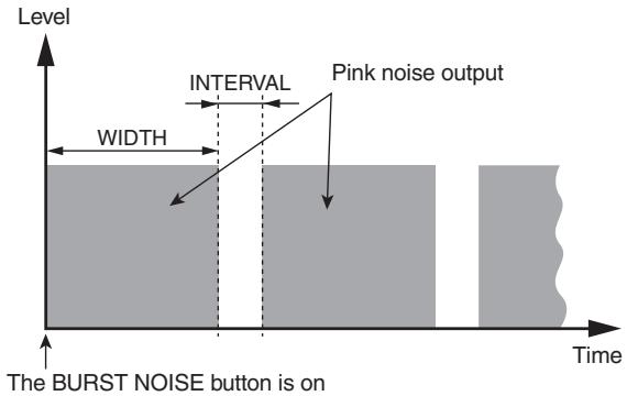
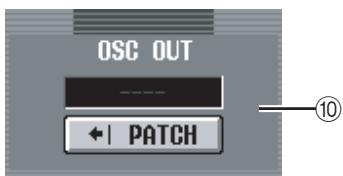
⑩ OSC OUT (Oscillator direct output)
This indicates the channel of the output jack / slot that directly outputs the oscillator signal. If you want to change the output destination, click the PATCH button to access the OUTPUT PATCH screen.
If SINE WAVE 2CH is selected, the L channel of the oscillator is sent to the oscillator direct output.
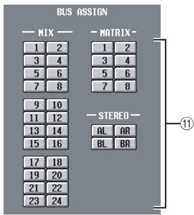
⑪ BUS ASSIGN
Here you can select the bus(es) or output jack(s) from which the sine wave or noise will be sent. (Multiple selections are allowed.)
AL/AR STEREO A bus L/R channels
BL/BR STEREO B bus L/R channels
If SINE WAVE 2CH is selected, the L channel of the oscillator is output to the odd-numbered bus or the L jack, and the R channel of the oscillator is output to the even-numbered bus or the R jack.
2TR I/O screen
This screen contains various settings and indications for 2TR IN / 2TR OUT.
Note
The 2TR I/O screen is disabled if the DSP5D is selected.
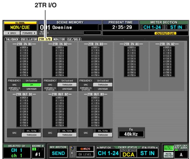
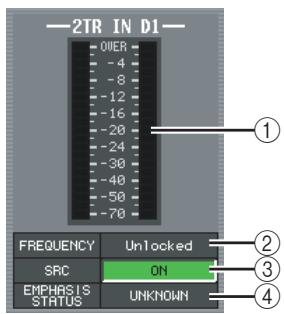
① Input level meters
These indicate the input level of 2TR IN DIGITAL jacks 1-3 and 2TR IN ANALOG jacks 1-2.
(2) FREQUENCY (Sampling frequency)
Indicates the sampling frequency of the input signal from 2TR IN DIGITAL jacks 1-3.
③ SRC (Sampling Rate Converter)
These are on/off switches for the sampling rate converters built into 2TR IN DIGITAL jacks 1-3. (If turned off, this indicates "THROUGH.")
(4) EMPHASIS STATUS
Indicates whether emphasis processing is being applied to the input signal from 2TR IN DIGITAL jacks 1-3.
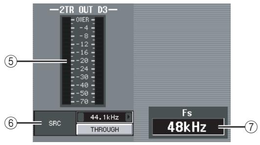
⑤ Output level meter
Indicates the output level of 2TR OUT DIGITAL jacks 1-3.
⑥ SRC (Sampling Rate Converter)
These are on/off and output frequency select switches for the sampling rate converters built into 2TR OUT DIGITAL jacks 1-3. As the output frequency you can select either 44.1kHz or 48kHz . The on/off button selects either ON or THROUGH (off).
(7) Fs (Sampling frequency)
This indicates the sampling frequency at which the PM5D is operating.
MONITOR screen
Here you can make settings and perform operations related to monitoring.
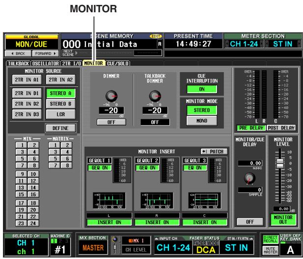
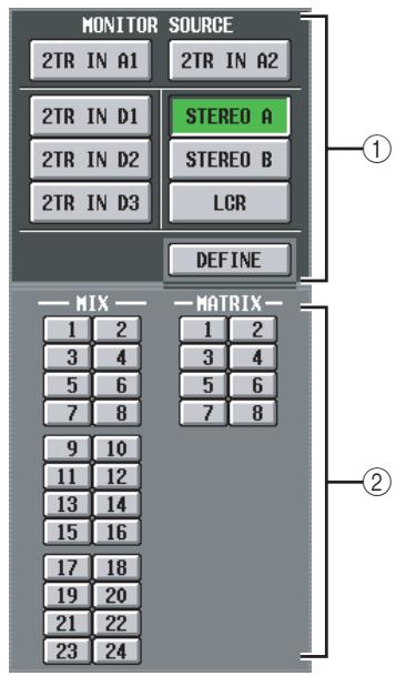
① MONITOR SOURCE
Selects the source that will be monitored from the L/R/ C MONITOR OUT jacks. You can select one from 2TR IN A1/A2, 2TR IN D1-D3, or DEFINE, and also simultaneously select one from STEREO A/B or LCR. These buttons are linked with the various keys of the MONITOR section in the top panel.
| 2TR IN A1 | 2TR IN ANALOG jack 1 input signal |
| 2TR IN A2 | 2TR IN ANALOG jack 2 input signal |
| 2TR IN D1 | 2TR IN DIGITAL jack 1 input signal |
| 2TR IN D2 | 2TR IN DIGITAL jack 2 input signal |
| 2TR IN D3 | 2TR IN DIGITAL jack 3 input signal |
| STEREO A | STEREO A channel output signal (*) |
| STEREO B | STEREO B channel output signal (*) |
| LCR | LCR channel output signal (*) |
| DEFINE | The signal selected in the DEFINE section (②) of this screen |
If a monitor source indicated by (^*) is selected, the signal that is output will change depending on whether
the USE AS STEREO BUS button or the USE AS CEN-TER BUS button is turned on in the STEREO B section of the MIXER SETUP screen ( p.222).
□ If the USE AS STEREO BUS button is on
| Monitor source | L | R | C |
| ST A | STEREO A L | STEREO A R | — |
| ST B | STEREO B L | STEREO B R | |
| LCR | — | — |
If the USE AS CENTER BUS button is on
| Monitor source | L | R | C |
| ST A | STEREO A L | STEREO A R | — |
| ST B | — | — | STEREO B L |
| LCR | STEREO A L | STEREO A R |
② DEFINE
If "DEFINE" is selected in the MONITOR SOURCE section, you can choose the signal that will be monitored from the following.
MIX 1-24 MIX bus 1-24 output signal
MATRIX 1-8. MATRIX bus 1-8 output signal
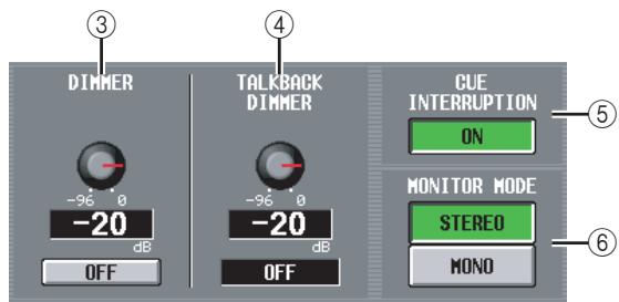
③ DIMMER
When you turn this button on, the level of the signal being monitored will be temporarily attenuated. The knob adjusts the amount of attenuation that will occur when the button is on. The range of adjustment is -96dB to 0dB . While this button is on, the DIMM indicator will appear in the upper right of the display.
Hint
You can also use an external switch connected to the GPI IN connector to switch the dimmer on/off. To do so, assign the MONITOR DIMMER ON function to the GPI IN port to which the switch is connected. (→ p.194).
(4) TALKBACK DIMMER
This adjusts the amount by which the monitor signal will be attenuated when talkback is on. The range of adjustment is -96dB to 0dB . The talkback on/off status is shown in the box below.
(5) CUE INTERRUPTION
If this button is on, the cue/solo signal will also be output from the MONITOR OUT jacks while the Cue/ Solo function is active. During this time, the monitor source selected in the MONITOR SOURCE section will be disabled.
If this button is off, the cue/solo signal will never be output from the MONITOR OUT jacks.
⑥ MONITOR MODE
Here you can select one of the following two ways in which the signal will be output from the MONITOR OUT jacks.
STEREO .... The L/R channels will be output in stereo.
MONO .... The L/R channels will be mixed, and output in monaural.
The status of these two buttons is linked with on/off operations of the [MONO] key in the MONITOR section of the panel.
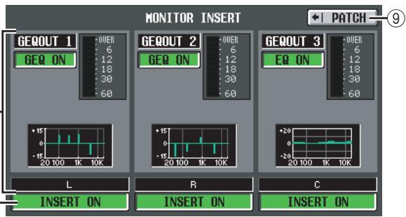
⑦ MONITOR INSERT
This area shows the input jacks (and input channels of the digital I/O card) that are inserted into the MONITOR OUT L/C/R channels. The input level of the inserted signal is shown by the level meter at the right. If GEQ or EFFECT is inserted, the corresponding information is shown here.
(8) INSERT ON/OFF
This button enables/disables insertion.
⑨ PATCH
Displays the INSERT RET PATCH screen.
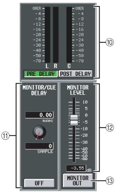
10 Level meter
These peak level meters indicate the level of the output signal from the MONITOR OUT jacks. You can select the level detection point to be immediately before the delay that is provided on the MONITOR/CUE bus output (when the PRE DELAY button is on) or immediately after the delay (when the POST DELAY button is on).
⑪ MONITOR / CUE DELAY
Here you can make settings for the delay function provided on the MONITOR/CUE bus output. Use the knob to specify the delay time (0-1000 msec), and use the ON/OFF button to switch the delay on/off. If the ON/OFF button is on, the monitor signal and cue signal will be delayed by the specified time. The delay time units can be changed in the DELAY SCALE field found in each screen of the INPUT DELAY/OUTPUT DELAY function.
⑫ MONITOR LEVEL
The level of the signal sent from the MONITOR OUT jacks is set by the level (digital) you adjust here together with the level (analog) adjusted by the MONITOR [LEVEL] knob on the top panel of the PM5D.
13 MONITOR OUT
Switches the signal sent from the MONITOR OUT jacks on/off.
CUE/SOLO screen
Here you can make settings and perform operations related to the Cue/Solo function.
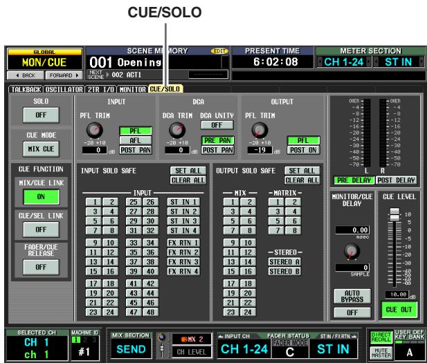
① SOLO ON/OFF
This button selects either CUE mode or SOLO mode as the type of monitoring performed by the [CUE] key. When you turn this button on, a confirmation message will appear. Each mode operates as follows.
- CUE mode (SOLO ON/OFF button is off)
The signal of the channel whose [CUE] key is pressed will be sent to the dedicated CUE bus, and monitored via the CUE bus from the CUE OUT jacks, MONITOR
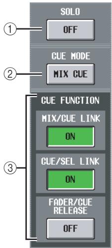
OUT jacks (if CUE INTERRUPTION is on), and PHONE jack. This mode lets you monitor the signal of a specific channel without affecting other buses.
- SOLO mode (SOLO ON/OFF button is on)
When using Input Solo, the familiar "solo" function is enabled; only the signal of the channel whose [CUE] key is pressed will be sent to the MIX, MATRIX, and STEREO A/B buses, and other channels will be muted. When using Output Solo, only that channel will be on. The signal of a channel whose [CUE] key is pressed can also be monitored from the CUE OUT jacks, MONITOR OUT jacks, and PHONES jack.
(2) CUE MODE
This button selects one of the following two possibilities for when the [CUE] key of more than one channel is pressed.
- MIX CUE mode
All channels / DCA groups whose [CUE] key is on will be mixed for monitoring.
Note
As an exception to MIX CUE, turning on a CUE button in the EFFECT PARAM screen or GATE PARAM screen or turning on a CUE button in the DME CONTROL screen (EXTERNAL CUE) will give priority to monitoring only the corresponding signal. (Any [CUE] keys that had been on until then will be forcibly defeated.)
LAST CUE mode
Only the channel / DCA group whose [CUE] key was pressed last will be monitored.
(3) CUE FUNCTION
These buttons let you turn on/off various functions related to Cue. You can select the following functions.
- MIX CUE LINK
Specifies whether cue operations will be linked to MIX channel selection. If this button is on, pressing the mix key selected in the ENCODER MODE section of the panel once again will simultaneously switch on the [CUE] key of that channel.
- CUE/SEL LINK
Specifies whether channel selection will be linked with cue operations. If this button is on, pressing the [CUE] key of a channel will simultaneously select that channel and light its [SEL] key.
- FADER/CUE RELEASE
This specifies whether cue operations will be restricted according to the fader position. If this button is on, cue will be defeated if you raise the fader from the - dB position for a channel whose [CUE] key is lit. For a channel whose fader is above the
- dB position, cue operation will not be possible.
(Pressing the [CUE] key will do nothing.) This means that cue can be turned on only when the fader is at the - dB position.
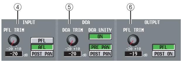
(4) INPUT
Here you can select the position from which an input channel will be cued.
PFL (Pre-Fader Listen)
............ Immediately before the fader
AFL (After-Fader Listen)
............ Immediately after the fader
POST PAN . Immediately after pan
If you select PFL, you can also use the knob located at the left to adjust the output level in a range of -20dB to +10dB .
⑤ DCA
Here you can make cue output settings for DCA groups.
- DCA TRIM
Adjusts the level of cue output from a DCA group in a range of -20dB to +10dB .
DCAUNITY
If this button is on, pressing a DCA [CUE] key will always monitor the corresponding DCA group at unity gain (the same level at when the DCA fader is at 0 dB).
Hint
- If you leave the DCA UNITY button on, you will be able to monitor the desired DCA group even if that DCA group is muted or its fader is lowered.
- Even when the DCA UNITY button is on, the value specified by the DCA TRIM knob is still valid. (In this case, the DCA TRIM knob specifies an offset value relative to unity gain.)
PRE PAN/POST PAN
This selects whether the pre-pan signal (PRE PAN button on) or the post-pan signal (POST PAN button is on) will be monitored when the DCA [CUE] button is turned on.
⑥ OUTPUT
Here you can select the position from which an output channel will be cued.
PFL (Pre-Fader Listen)
............ Immediately before the fader
POST ON ... Immediately after the [ON] key If you select PFL, you can also use the knob located at the left to adjust the output level in a range of -20dB to +10dB .
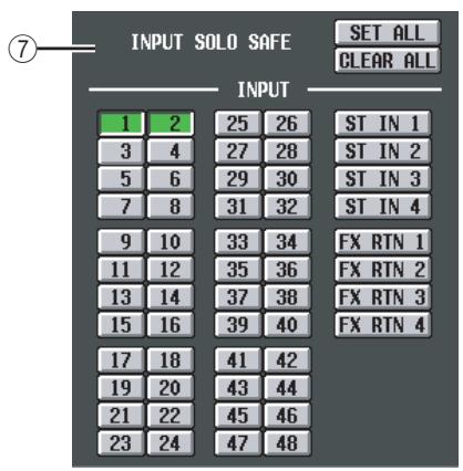
⑦ INPUT SOLO SAFE
Here you can specify input channels that will be excluded from Solo operations. (You can specify more than one.) The buttons correspond to the following input channels.
| INPUT 1–48 | Input channels 1–48 |
| ST IN 1–4 | ST IN channels 1–4 |
| FX RTN 1–4 | FX RTN channels 1–4 |
| SET ALL | Sets all input channels to the Solo Safe condition |
| CLEAR ALL | Defeats the Solo Safe setting for all input channels |
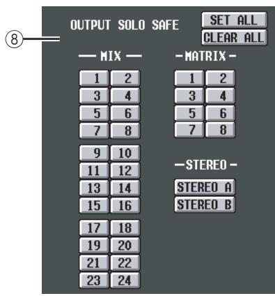
⑧ OUTPUT SOLO SAFE
Here you can specify output channels that will be excluded from Solo operations. (You can specify more than one.) The buttons correspond to the following output channels.
| MIX 1–24 | MIX channels 1–24 |
| MATRIX 1–8 | MATRIX channels 1–8 |
| STEREO A/B | STEREO A/B channels |
| SET ALL | Sets all output channels to the Solo Safe condition |
| CLEAR ALL | Defeats the Solo Safe setting for all output channels |
Hint
Solo Safe settings and Cue on/off operations are linked for paired channels. Solo Safe operations can be performed independently of the scene memory.
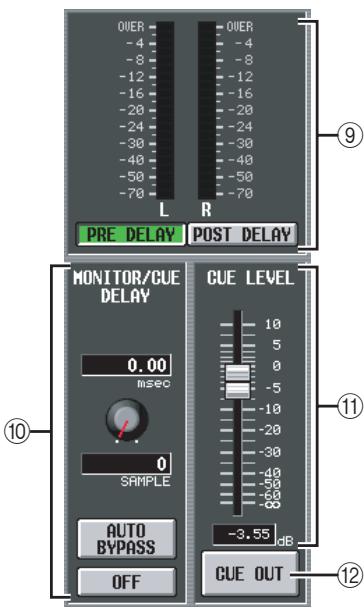
⑨ Level meter
This is a peak level meter that indicates the level of the signals output from the CUE OUT jacks. You can select the level detection point to be immediately before the delay that is provided on the MONITOR/CUE bus output (when the PRE DELAY button is on), or immediately after the delay (when the POST DELAY button is on).
⑩ MONITOR / CUE DELAY
Here you can make settings for the delay function provided on the MONITOR/CUE bus output. Use the knob to specify the delay time (0-1000 msec), and use the DELAY button to switch the delay on/off. In general, this is linked with the MONITOR/CUE DELAY setting in the MONITOR screen. However, the difference is that in this screen, turning the AUTO BYPASS button on lets you automatically bypass the delay when you perform the Cue any input channels.
CUE LEVEL
The level of the signal sent from the CUE OUT jacks is set by the level (digital) you adjust here together with the level (analog) adjusted by the CUE [LEVEL] knob on the top panel of the PM5D.
⑫ CUE OUT
Switches the cue output on/off.
Output functions
OUTPUT PATCH function
OUTPUT PATCH screen
Here you can make patch settings to send output channel signals to the outputs of I/O cards installed in the MIX OUT jacks and slots, to the input of internal effects, and to the 2TR OUT DIGITAL jacks.

OUTPUT PATCH
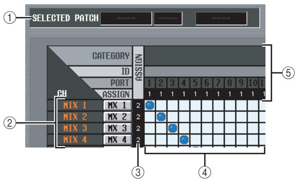
① SELECTED PATCH
This indicates the output channel number, name and output port of the grid at which the cursor is located.
CH (Output channel)
This is the number and name of the output channel (MIX channel, MATRIX channel, STEREO A/B channel, MONITOR L/R/C channel, CUE L/R channel, TALKBACK OUT channel, OSC OUT channel) whose output destination will be patched. The channel number at which the cursor is located will be highlighted. When you click the name area, a window will appear, allowing you to assign a name to the channel.
Note
On the PM5D, this is unavailable for the CUE L/R channels; on the DSP5D, this is unavailable for the MONITOR L/R/C channels.
③ ASSIGN
For each output channel, this indicates the number of output ports that are currently assigned.
④ Grid
This grid lets you patch output ports (horizontal rows) to output channels (vertical columns). Currently-patched grids are indicated by a symbol. By clicking a grid location you can set/cancel patching.
The red lines at the left and top indicate the grid location to which you move the cursor.
Hint
- If PATCH CONFIRMATION is turned on in the PREFERENCE 1 screen (UTILITY function), a confirmation message will appear each time you attempt to change a patch setting. If STEAL PATCH CONFIRMATION is turned on, a confirmation message will also appear when you attempt to make patch settings that would cause an existing patch to be modified.
To move the cursor location rapidly in or out of the grid, hold down the [SHIFT] key and press the CURSOR []/[]/[] keys. - To move rapidly to left or right inside the grid, turn the [DATA] encoder. To move up or down, hold down the [SHIFT] key and turn the [DATA] encoder.
Note
You can patch an output channel to more than one output port, but you cannot patch multiple output channels to a single output port.
⑤ Output port
From the top, this area indicates the type of output port, the ID number, the output channel number, and the number of output channels assigned. The following types of output port can be selected.
| MIX OUT | MIX OUT jacks 1-24 |
| SLOT OUT | Output channels of an I/O card installed in slots 1-4 |
| FX IN | L/R inputs of internal effects 1-8 (MIX chan- nels are the only output channels that can be selected) |
| 2TR OUT | L/R channels of 2TR OUT DIGITAL jacks 1-3 |
Note
On the DSP5D, you can choose from OMNI OUT 1-24, SLOT OUT 1-4 (SLOT OUT 3-4 is the CASCADE OUT connector), and FX IN 1-8.
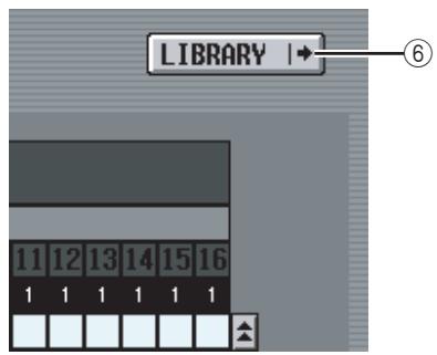
(6) LIBRARY button
This button accesses the OUTPUT PATCH LIBRARY screen ( p.247), where you can store/recall patch library settings for output channels.
Hint
- The signal from immediately after the delay and immediately before the output port attenuation will be sent to output ports you patch in this screen. Subsequently, in the case of SLOT OUT and 2TR OUT, the specified output port attenuation will be applied respectively.
- The rear panel MATRIX OUT jacks 1–8, and STEREO OUT jacks A/B always output the signal of the corresponding output channel. They are not affected by the settings in this screen.
INSERT PATCH screen
In this screen you can patch the input/output ports into which external devices will be inserted. Select the output port in the left side of the screen, and the input port in the right side of the screen.
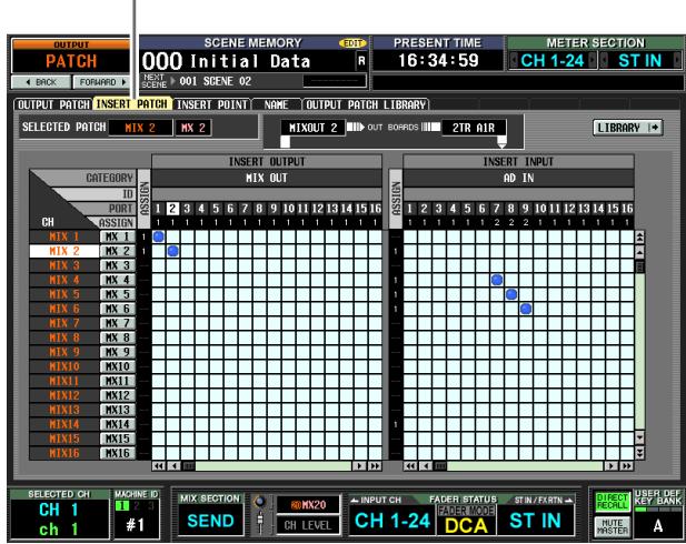
INSERT PATCH

① SELECTED PATCH
This indicates the number and name of the output channel at which the cursor is located in the grid.
② Insert in/out
This indicates the input/output ports that are patched as insert in/out for the output channel at which the cursor is located. If multiple ports are assigned for insert-out, only the first port is displayed.
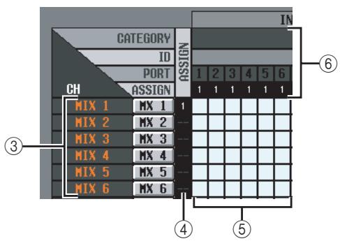
③ CH (Output channel)
This area shows the numbers and names of the output channels (MIX channels, MATRIX channels, STEREO A/B channels, MONITOR L/R/C channels). The channel number at which the cursor is located will be highlighted. When you click the name area, a window will appear, allowing you to assign a name to the channel.
Note
On the DSP5D, this is unavailable for the MONITOR L/R/C channels.
④ ASSIGN
For each output channel, this indicates the number of output ports that are currently assigned as insert-out.
⑤ Grid
For each output channel (vertical column), this grid lets you can patch one or more output ports (horizontal row) to be used as insert-outs. Currently-patched grids are indicated by a symbol.
By clicking a grid location you can set/cancel patching. The red lines at the left and top indicate the grid location to which you move the cursor.
Hint
Operations in the grid are the same for all of the patching screens. For details, refer to the Hint on p.243.
⑥ Output port
From the top, this area indicates the type of output port, the ID number, the output channel number, and the number of output channels assigned. The following types of output port can be patched as insert-out.
| MIX OUT | MIX OUT jacks 1–24 |
| SLOTOUT | Output channels of an I/O card installed in slots 1–4 |
| FX IN | L/R inputs of internal effects 1–8 |
| GEQ IN | Inputs of internal GEQ modules 1–20 |
| 2TR OUT | L/R channels of 2TR OUT DIGITAL jacks 1–3 |
Note
On the DSP5D, you can choose from OMNI OUT 1-24, SLOT OUT 1-4 (SLOT OUT 3-4 is the CASCADE OUT connector), FX IN 1-8, and GEQ IN 1-20.
Hint
If you select FX IN as an insert-out, the output of the same internal effect will automatically be selected as the insert-in. If you select GEQ IN, the output of the same GEQ module will automatically be selected as the insert-in.
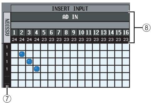
⑦ ASSIGN
For each input channel, this indicates the number of input ports that are currently assigned as insert-in.
⑧ Input port
From the top, this area indicates the type of input port, the ID number, the input channel number, and the number of input channels assigned. The following types of input port can be selected.
| AD IN | INPUT jacks 1–48 |
| AD ST IN | ST IN jacks 1–4 L/R |
| SLOT IN | Input channels of an I/O card installed in slots 1–4 |
| FX OUT | L/R outputs of internal effects 1–8 |
| GEQ OUT | Outputs of GEQ modules 1–20 |
| 2TR IN | L/R channels of 2TR IN DIGITAL jacks 1–3 and 2TR IN ANALOG jacks 1/2 |
Note
On the DSP5D, you can choose from OMNI OUT 1-24, SLOT OUT 1-4 (SLOT OUT 3-4 is the CASCADE OUT connector), FX IN 1-8, and GEQ IN 1-20.
⑨ LIBRARY button
This button accesses the OUTPUT PATCH LIBRARY screen ( p.247), where you can store/recall patch library settings for output channels.
□ Using the [SHIFT] key + CURSOR [<]/[▶] to move the cursor
When operating from the panel, you can move the cursor from the right side of the screen to the left side (or vice versa) by holding down the [SHIFT] key and using the CURSOR [] /[▶] keys.
To quickly move the cursor in or out of the grid, hold down the [SHIFT] key and press the CURSOR []/[]/[] /[▼] keys.
![YAMAHA PM5D-RH - □ Using the [SHIFT] key + CURSOR [<]/[▶] to move the cursor - 1](/content/2025/01/115055/images/d12574738d54efa5ea52287c98db46c45c8558b0be8746e6b31c5b3fd24e082e.jpg)
Note
To enable an insert-in assigned to an output channel in this screen, you must turn on the ON/OFF button for the corresponding output channel in the INSERT POINT screen (OUTPUT PATCH function). ( p.246) However, the insert-out is always on, regardless of the state of the ON/OFF button. An exception to the above is that if you insert GEQ, its insert-in will automatically be on.
INSERT POINT screen
In this screen you can select the position at which the insert-in/out of each output channel will be patched. Here you can also switch insert-in on/off.
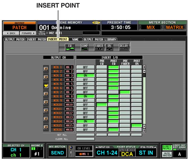
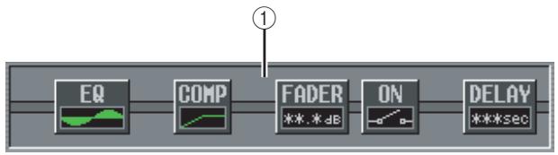
① Insert view
When you move the cursor to the insert I/O point (④), the insert point for that output channel will be shown graphically.
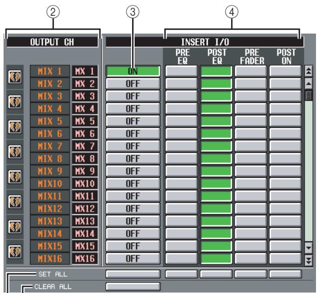

② OUTPUT CH (Output channel)
This is the number and name of the output channel you are editing. Two paired channels are indicated by a heart symbol shown at the left; settings ③-④ will be linked for these channels. You can click this symbol to enable/disable pairing.
③ ON/OFF (Insert on/off)
This button switches insert on/off for each channel.
This is linked for paired channels.
Be aware that if you turn on this button when either insert-in or insert-out are unpatched, the signal will no longer be output from the corresponding output channel.
④ INSERT I/O (Insert I/O point)
Here you can select one of the following as the insertin/out location for each output channel.
Note
| PRE EQ | Immediately before the EQ |
| POST EQ | Immediately after the EQ |
| PRE FADER | Immediately before the fader |
| POST ON | Immediately after the [ON] key |
⑤ SET ALL
Turns on the corresponding item (insert or the insert point) for all channels (including channels not currently shown in the screen).
⑥ CLEAR ALL
Turns insert off for all channels (including channels not currently shown in the screen).
NAME screen
Here you can assign names to the output channels. However, display in the CH COPY, GLOBAL PASTE, and CSV IMPORT/EXPORT functions is not supported.
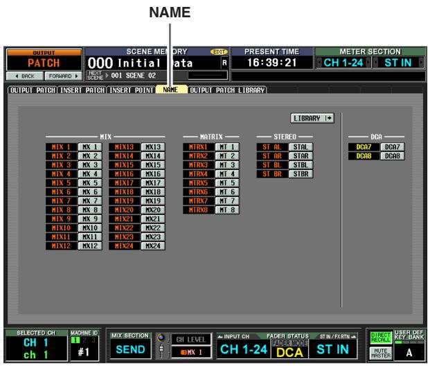
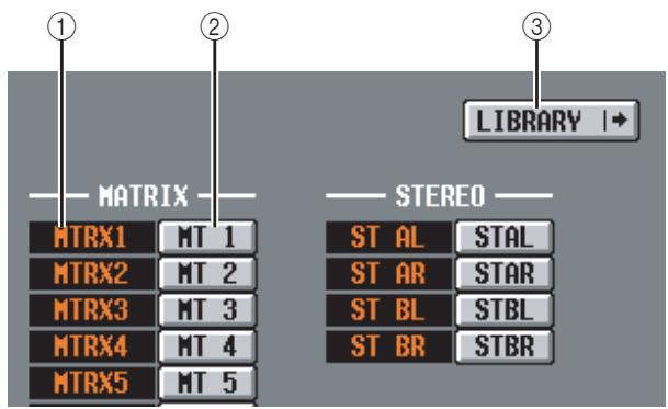
① Channel
This is the number of the output channel (MIX channel, MATRIX channel, or STEREO A/B channel).
② Name
This is the name currently assigned to the output channel. When you click the name area, a window will appear, allowing you to assign a name to the channel.
③ LIBRARY
This button displays the OUTPUT PATCH LIBRARY screen (p.247) where you can store or recall the state of the output channel patching (and names) as library data.
OUTPUT PATCH LIBRARY screen
Here you can recall, store, rename, or delete items in the output patch library.
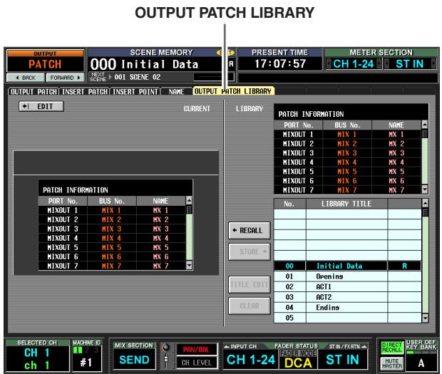
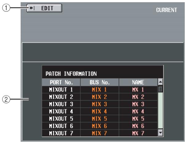
① EDIT
When you click this button, the OUTPUT PATCH screen will appear.
② Patch information for the current scene
This area shows the output patch settings for the current scene.
Note
If a DSP5D (machine #2 or #3) is selected as the target of control, this information will not be displayed.
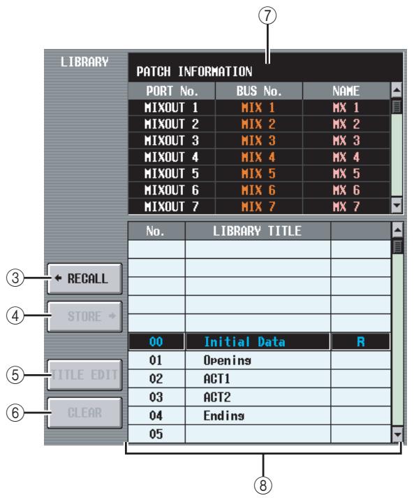
③ RECALL
Recalls the output patch library item selected in the list into memory.
(4) STORE
Stores the current settings of the OUTPUT PATCH screen into the location selected in the list. When you click this button a window will appear, allowing you to name and save the settings.
(5) TITLE EDIT
Edits the title of the library item selected in the list. When you click this button a window will appear, allowing you to edit the title.
⑥ CLEAR
Deletes the library item selected in the list. When you click this button, a confirmation message will appear.
Note
Library items with an "R" displayed in the right column of the list are read-only. Read-only items cannot be stored, renamed, or deleted.
⑦ Patch settings of the library item
Displays the settings of the library item selected in the list.
⑧ Library list
Use the scroll bar to select the library item on which you want to perform an operation. The selected library item will move to the center, and will be highlighted.
OUTPUT INSERT function
INSERT IN MIX 1-24 screen
INSERT IN MATRIX/STEREO/MONITOR screen
Here you can make settings for the internal HA (PM5D-RH model only) or external HA assigned to the insert-in of an output channel or MONITOR L/C/R channel.
INSERT IN MIX1-24
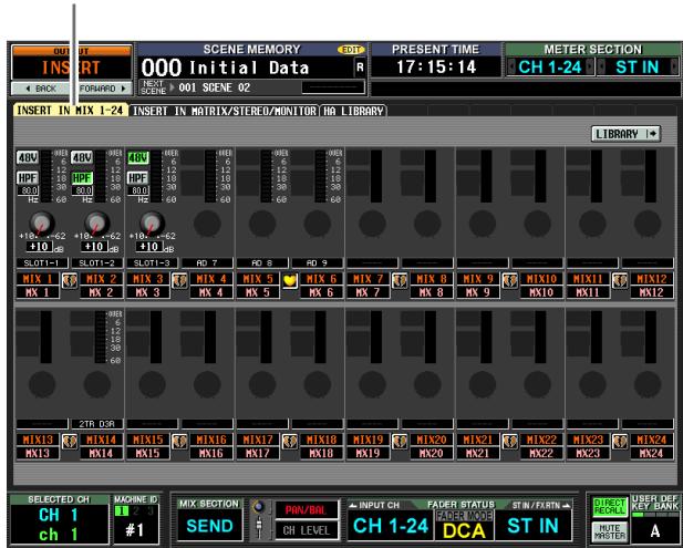
INSERT IN MATRIX/STEREO/MONITOR
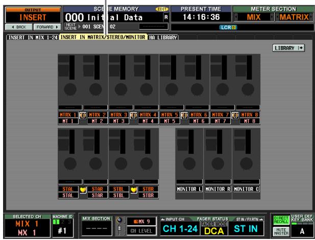
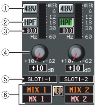
① + 48V
Switches phantom power (+48V) on/off for each channel.
② HPF (High Pass Filter)
Turns the HPF on/off for each channel.
③ Cutoff frequency
Specifies the HPF cutoff frequency for each channel. Move the cursor to the box, and turn the [DATA] encoder to adjust the cutoff frequency in a range of 20-600 Hz.
(4) GAIN
Adjusts the gain for each channel. Move the cursor to the knob, and turn the [DATA] encoder to adjust the attenuation in a range of +10 dB to -62 dB. The current value is shown in the box below each knob.
Note
Since settings 1-4 are for the patched input port, they are linked for channels that are patched to the same port.
⑤ Input port
This indicates the type and number of the input port assigned to the insert-in of that channel.
Note
- Items ①-④ are not shown for channels to whose insert-in nothing is patched, or for channels patched to an input port that does not have a HA. Items ② and ③ are not shown for channels patched to a port that has no high pass filter.
- Use the INSERT Patch screen (OUTPUT PATCH function) to patch an input port to an insert-in.
⑥ Channel
This is the number and name of the channel you are editing. Two paired channels are indicated by a heart symbol displayed between them.
Note
HA settings are not linked even if two channels are paired. However, the GAIN knob setting is linked for HAs whose GANG button is turned on in the HA screen (SYS/W.CLOCK function).
Hint
The HA settings you edit in this screen are also reflected in the HA screen (SYS/W.CLOCK function).
HA LIBRARY screen
This screen is shared with HA LIBRARY in the SYS/ W.CLOCK function ( p.230).

HA LIBRARY
OUTPUT EQ function
EQ PARAM (EQ Parameter) screen
Here you can edit the EQ parameters of the selected output channel.
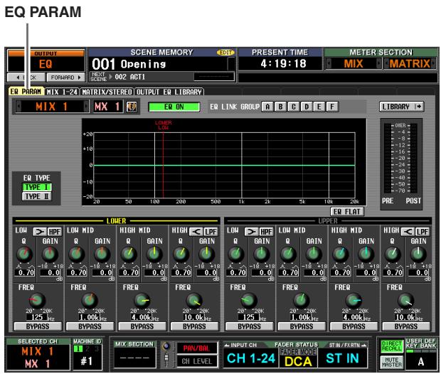
(If a MIX channel or STEREO A/B channel is selected)
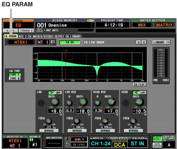
(If a MATRIX channel is selected)
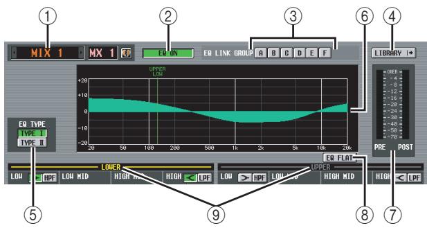
① Channel selection
Select the output channel that you want to edit. You can use eight-band EQ (four UPPER bands + four LOWER bands) for MIX channels and STEREO A/B channels, and four-band EQ for MATRIX channels. If a channel is paired (or if a STEREO A/B channel is selected), a heart symbol is displayed at the right. For MIX channels or MATRIX channels, you can click this symbol to enable/disable pairing.
② EQ ON/OFF (EQ on/off)
Turns the EQ on/off for that channel.
③ EQ LINK GROUP
Selects the EQ link group (A-H) to which the EQ of that channel belongs. EQ parameters are linked for output channels belonging to the same group.
Note
The EQ of MIX channels and STEREO A/B channels can be assigned only to groups A - F , and the EQ of MATRIX channels can be assigned only to groups G / H
④ LIBRARY
This button accesses the OUTPUT EQ LIBRARY screen ( p.252), where you can store/recall EQ library settings for output channels.
⑤ EQ TYPE
Selects the type of EQ. Turning the TYPE I button on selects the algorithm used in the 02R series. Turning the TYPE II button on selects a newly developed algorithm. TYPE II reduces the interference between bands.
⑥ EQ graph
This graph shows the approximate response of the EQ parameters. The colored vertical lines indicate the FREQ (center frequency) of the band for the parameter at which the cursor is located. (The color of each line matches the knob markings for each band.) The response curve will change when you edit the Q or GAIN of each band.
(7) Level meter
These meters indicate the peak levels before EQ and after EQ. If the signal clips before EQ, the OVER segment will light.
⑧ EQ FLAT
This button resets the GAIN parameters of all bands to the default value (± 0.0 dB). When you click this button, a confirmation message will appear.
(9) LOWER/UPPER (only for MIX channels and STEREO A/B channels)
This indicator shows which four bands (LOWER or UPPER) are selected in the SELECTED CHANNEL section of the panel. The text label of the selected group is displayed in yellow.
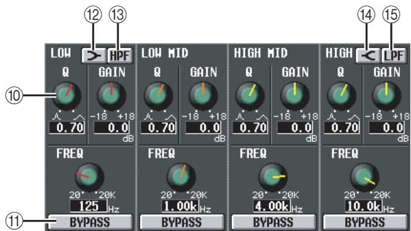
10 Knobs
These knobs adjust the Q, FREQ (center frequency), and GAIN (amount of boost/cut) for each band.
(1) BYPASS
These buttons bypass each band of the EQ.
(LOW shelving)
If this button is on, the LOW EQ will function as a shelving-type EQ. The Q knob will disappear.
HPF (High Pass Filter)
If this button is on, the LOW EQ will function as a high-pass filter. The Q knob will disappear, and the GAIN knob is used to switch the HPF on/off.
(14) (HIGH shelving)
If this button is on, the HIGH EQ will function as a shelving-type EQ. The Q knob will disappear.
LPF (Low Pass Filter)
If this button is on, the HIGH EQ will function as a low-pass filter. The Q knob will disappear, and the GAIN knob is used to switch the LPF on/off.
MIX 1-24 screen
MATRIX/STEREO screen
These screens list the EQ settings for all output channels. Here you can also copy EQ settings between output channels.
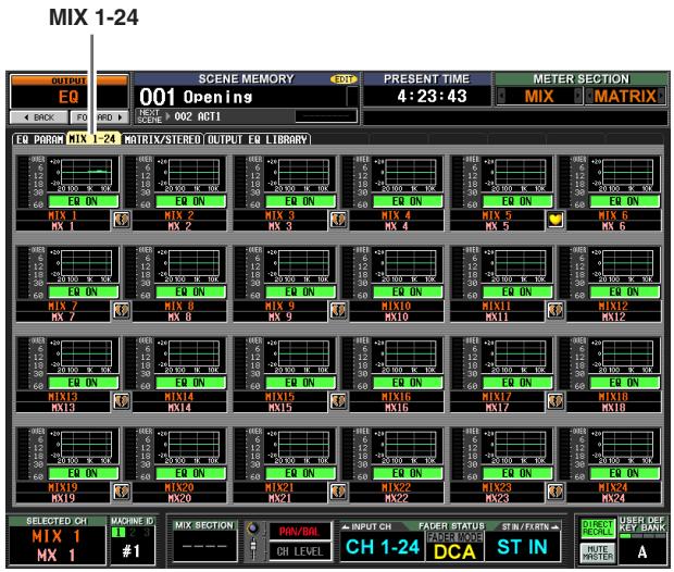
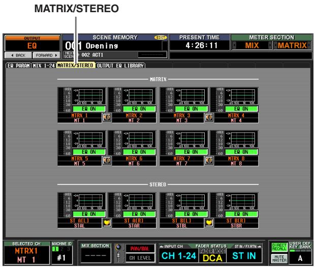
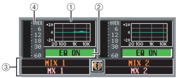
① EQ graph
This mini-graph shows the approximate EQ response for each output channel.
When you click the graph at which the cursor is currently located, the EQ PARAM screen for that channel will appear.
In this screen you can drag and drop the mini-graph from the desired channel to copy its EQ settings.
(When you drag and drop the mini-graph, a message will ask you to confirm the copy operation.)
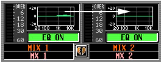
You can also copy EQ settings between the MIX 1-24 screen and the MATRIX/STEREO screen. First drag the mini-graph over the MIX 1-24 tab or MATRIX/STEREO tab in the screen (the screen will switch). Then drag and drop the mini-graph onto the desired channel, and a message will ask you to confirm the copy operation.
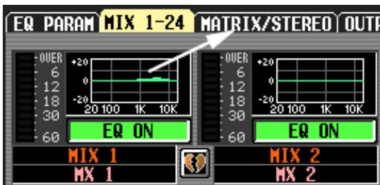
You can also copy settings between the eight-band EQ of a MIX channel or STEREO A/B channel and the four-band EQ of a MATRIX channel. In this case, only the LOWER four bands will be copied for MIX channels or STEREO A/B channels.
② EQ ON/OFF (EQ on/off)
Turns the EQ on/off for that channel. This is linked for paired channels.
③ Channel
This is the number and name of the channel you are editing. Two paired channels are indicated by a heart symbol displayed between them.
④ Level meter
This meter indicates the peak level after EQ. If the signal clips, the OVER segment will light.
OUTPUT EQ LIBRARY screen
Here you can recall, store, rename, or delete items in the output EQ library.
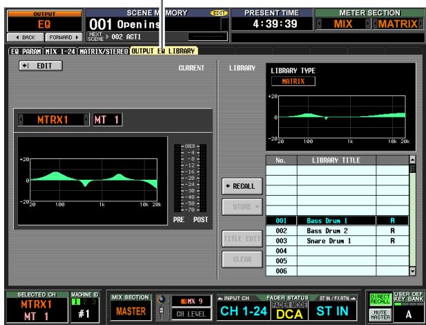
OUTPUT EQ LIBRARY
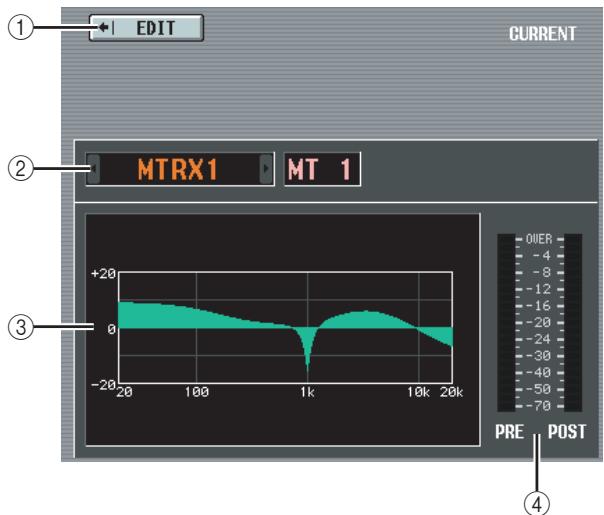
① EDIT
When you click this button, the EQ PARAM screen for the currently selected output channel will appear.
② Channel selection
Select the channel that you want to edit.
③ EQ graph for the selected channel
This graph shows the approximate response of the EQ for the currently selected channel.
(4) Level meter
These meters indicate the peak levels before EQ and after EQ. If the signal clips before EQ, the OVER segment will light.
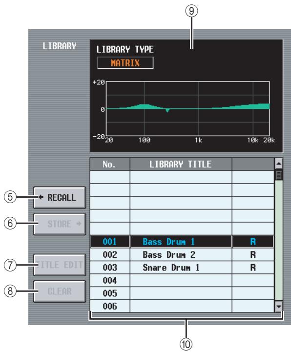
(5) RECALL
Recalls the EQ library item selected in the list into memory.
(6) STORE
Stores the EQ settings of the currently selected channel into the location selected in the list. When you click this button a window will appear, allowing you to name and save the settings.
(7) TITLE EDIT
Edits the title of the library item selected in the list. When you click this button a window will appear, allowing you to edit the title.
(8) CLEAR
Deletes the library item selected in the list. When you click this button, a confirmation message will appear.
Note
Library items with an "R" displayed in the right column of the list are read-only. Read-only items cannot be stored, renamed, or deleted.
⑨ Library EQ graph
This graph indicates the approximate response of the EQ library item selected in the list. The LIBRARY TYPE indication shows whether the item contains eight-band EQ settings (MIX, STEREO A/B or GEQ) or four-band EQ settings (MATRIX).
⑩ Library list
Use the scroll bar to select the library item on which you want to perform an operation. The selected library item will move to the center, and will be highlighted.
OUTPUT COMP function
COMP PARAM (Compressor parameter) screen
Here you can edit the compressor parameters of the selected output channel.
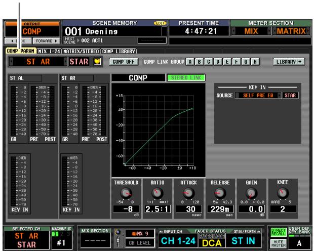
COMP PARAM
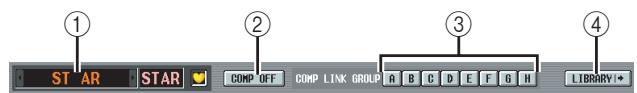
① Channel selection
Select the channel that you want to edit. If the corresponding MIX channel or MATRIX channel is paired (or if a STEREO A/B channel is selected), a heart symbol is displayed at the right. For MIX channels or MATRIX channels, you can click this symbol to enable/disable pairing.
② COMP ON/OFF (Compressor on/off)
Turns the compressor on/off for that channel.
(3) COMP LINK GROUP (Compressor link group)
- Selects the compressor link group (A-H) to which that channel belongs. Compressor parameters are linked for output channels belonging to the same group.
④ LIBRARY
This button accesses the COMP LIBRARY screen (p.256), where you can store/recall compressor library settings for output channels.
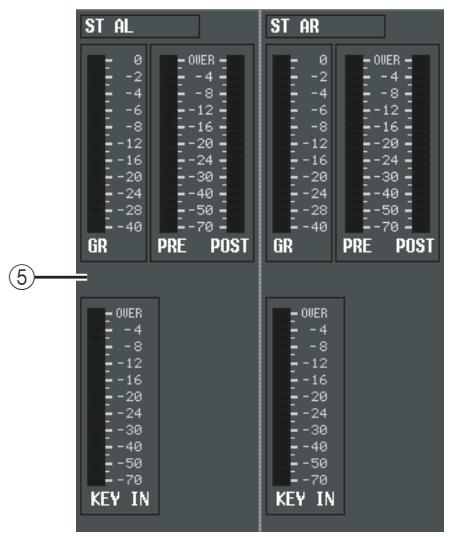
⑤ Level meters
These meters indicate the amount of gain reduction (GR), the peak level before (PRE) and after (POST) the compressor, and the peak level of the key-in signal (KEY IN) that causes the compressor to operate. If the signal clips, the OVER segment will light.
If stereo link is turned on for the corresponding MIX channel or MATRIX channel (or if a STEREO A/B channel is selected), level meters for two channels are displayed.
Hint
If GR METER ON/OFF LINK is turned on in the PREFER-ENCE 1 screen (UTILITY function), the gain reduction meter will not be displayed when the compressor is off.
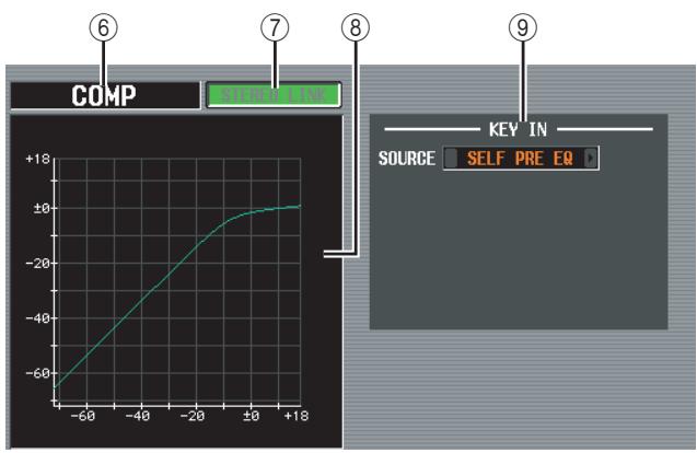
(6) Type
Indicates the type of the currently selected compressor.
Hint
To change the compressor type, use the OUTPUT COMP LIBRARY screen to recall a library item that has a different type. You cannot change the compressor type in this screen.
⑦ STEREO LINK
This specifies whether parameter settings and compressor operation by a key-in signal will be linked (STEREO LINK button on) for adjacent odd-numbered/even-numbered MIX/MATRIX channels or the L/R channels of the STEREO A/B channels, or not (STEREO LINK button off).
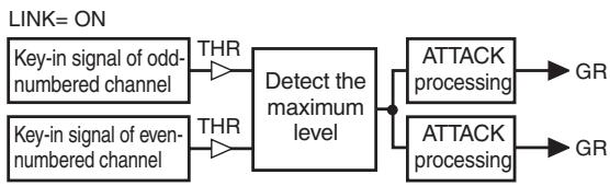
Key-in signal flow when Link=On
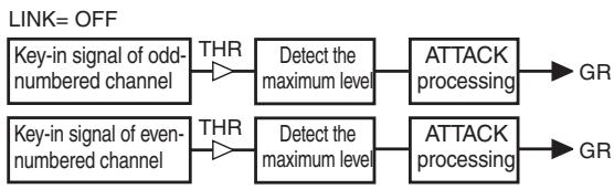
Key-in signal flow when Link= Off
Note
Stereo Link is fixed at On for paired channels and for STE-REO A/B channels.
⑧ Compressor graph
This graph displays the approximate response of the compressor.
(9) KEY IN SOURCE
Select the desired key-in signal from the following choices.
| SELF PRE EQ | The pre-EQ signal of the currently selected output channel |
| SELF POST EQ | The post-EQ signal of the currently selected output channel |
| MIX1-24 POST EQ | The post-EQ signal of the corresponding output channel (however, you can only select from the group to which that channel belongs, from the three groups MIX 1-12, MIX 13-24, and MATRIX/ST) |
| MATRIX1-8 POST EQ | |
| ST AL/AR POST EQ | |
| ST BL/BR POST EQ | |
| MIX21-24 | The output signal of the corresponding MIX channel immediately before the output patch |
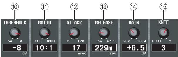
⑩ THRESHOLD (Threshold level)
Specifies the threshold level at which the compressor will operate. The input signal will start being compressed when the key-in signal exceeds this level; compression will be removed when the signal falls below this level.
11 RATIO
Specifies the ratio at which the input signal will be compressed when the key-in signal exceeds the threshold level.
⑫ ATTACK (Attack time)
Specifies the time from when the key-in signal exceeds the threshold level until compression begins.
⑬ RELEASE (Release time)
Specifies the time from when the key-in signal falls below the threshold level until compression is removed.
14 GAIN
Specifies the output level gain.
15 KNEE
Select the sharpness at which the output level changes; the range is HARD or 1-5. HARD produces the sharpest change, and 5 produces the most gradual change.
MIX 1-24 screen
MATRIX/STEREO screen
These screens show the compressor settings for all output channels. Here you can also copy compressor settings between output channels.
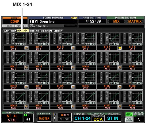
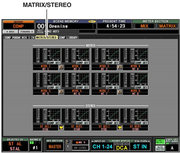
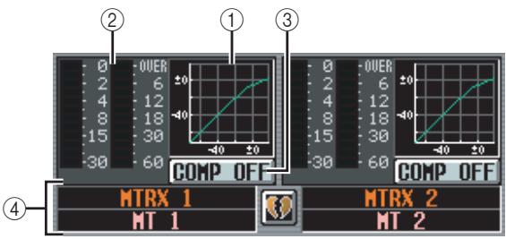
① Compressor graph
This mini-graph shows the approximate compressor response for each output channel.
When you click the graph at which the cursor is currently located, the COMP PARAM screen for that channel will appear.
In this screen you can drag and drop the mini-graph from the desired channel to copy its compressor settings. (When you drag and drop the mini-graph, a
dropdown window will ask you to confirm the copy operation.)
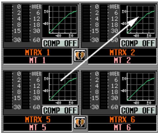
You can also copy compressor settings between the MIX 1-24 screen and the MATRIX/STEREO screen. First drag the mini-graph over the MIX 1-24 tab or MATRIX/STEREO tab in the screen (the screen will switch). Then drag and drop the mini-graph onto the desired channel, and a message will ask you to confirm the copy operation.
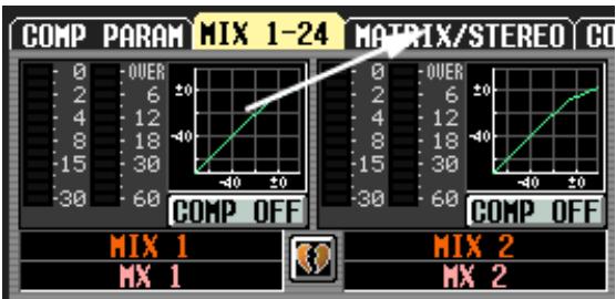
② Level meters
These meters show the amount of gain reduction produced by the compressor (at left), and the peak level of the signal after passing through the compressor (at right). If the signal clips, the OVER segment will light.
③ COMP ON/OFF (Compressor on/off)
Turns the compressor on/off for that channel.
④ Channel
This is the number and name of the channel you are editing. Two paired channels are indicated by a heart symbol displayed between them.
COMP LIBRARY (Compressor library) screen
Here you can recall, store, rename, or delete items in the compressor library. The contents of this screen are in common with the COMP LIBRARY screen of the INPUT GATE/COMP function.
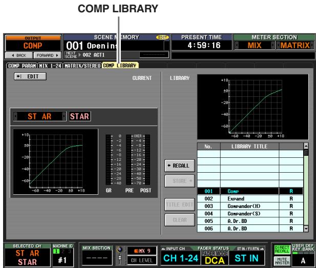
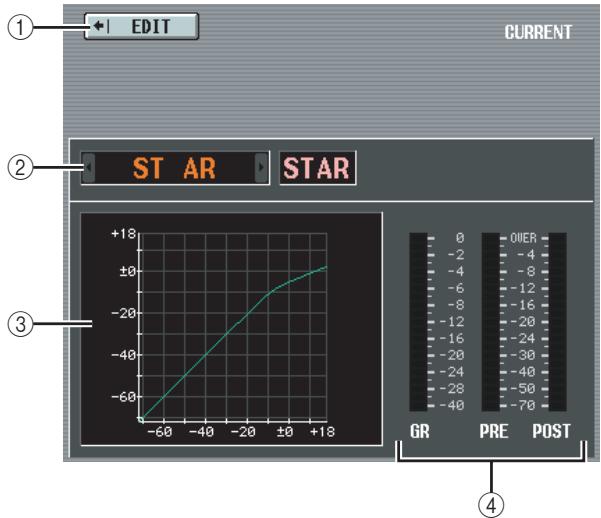
① EDIT
When you click this button, the COMP PARAM screen for the currently selected channel will appear.
② Channel selection
Select the channel that you want to edit.
③ Compressor graph of the selected channel This graph shows the approximate response of the compressor for the currently selected channel.
(4) Level meters
These meters show the amount of gain reduction (GR), and the peak levels before the compressor (PRE) and after the compressor (POST). If the signal clips, the OVER segment will light.
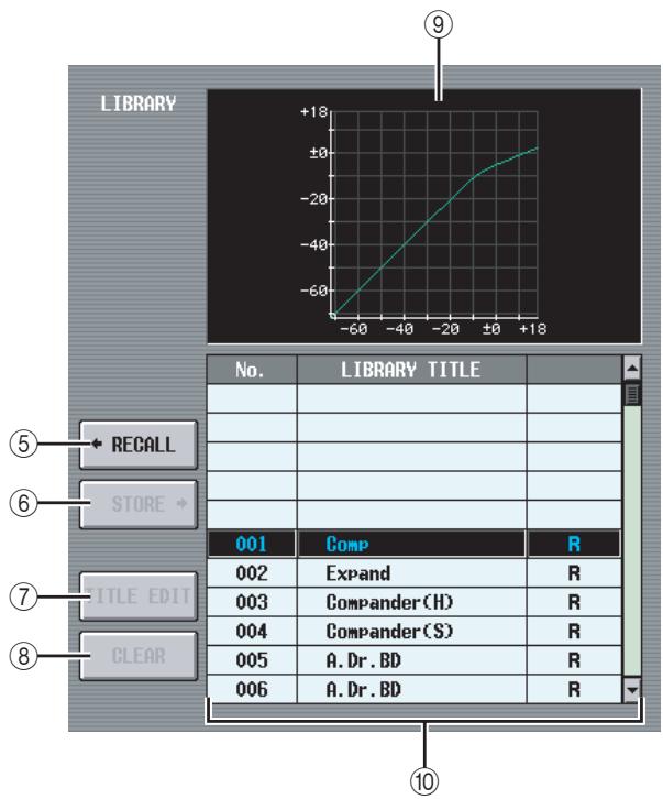
⑤ RECALL
Recalls the compressor library item selected in the list into memory.
STORE
Stores the compressor settings of the currently selected channel into the location selected in the list. When you click this button a window will appear, allowing you to name and save the settings.
(7) TITLE EDIT
Edits the title of the library item selected in the list. When you click this button a window will appear, allowing you to edit the title.
(8) CLEAR
Deletes the library item selected in the list. When you click this button, a confirmation message will appear.
Note
Library items with an "R" displayed in the right column of the list are read-only. Read-only items cannot be stored, renamed, or deleted.
⑨ Compressor graph of the library item
This graph indicates the approximate response of the compressor library item selected in the list.
⑩ Library list
Use the scroll bar to select the library item on which you want to perform an operation. The selected library item will move to the center, and will be highlighted.
OUTPUT DELAY function
MIX 1-24 screen
MATRIX/STEREO screen
Here you can edit the delay parameters of the selected output channel.
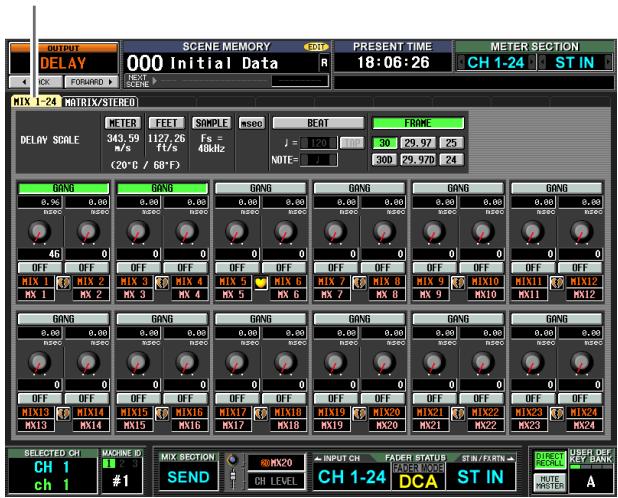
MIX1-24
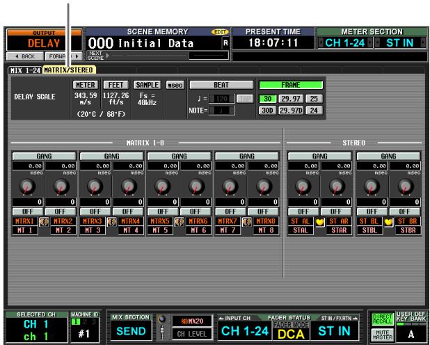
MATRIX/STEREO
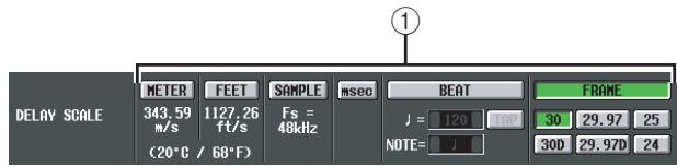
① DELAY SCALE
The unit you select here is used to indicate the delay time in the box below the delay time knob (③) and in other screens. You can choose one of the following units.
METER
The distance in meters, calculated as the speed of sound at an air temperature of 20^ (343.59m / s) x the delay time (seconds).
FEET
The distance in feet, calculated as the speed of sound at an air temperature of 20^ (68^) (1127.26 feet/s) x the delay time (seconds).
- SAMPLE
The delay time is shown as a number of samples. If you change the sampling frequency at which the PM5D operates, the number of samples will change accordingly.
- msec (milliseconds)
The delay time is shown in units of milliseconds. If this button is on, the boxes above and below the delay time knob (③) will show the same values.
BEAT
The delay time is shown in units relative to the note length (considered as 1.0) specified by the tempo (BPM) and note value (NOTE).
To specify the tempo, you can either use the 1 / 2 buttons located immediately below the BEAT button, or repeatedly tap (click) the TAP button, or repeatedly click a User Defined key that is assigned to [TAP TEMPO]-[CURRENT PAGE].
- FRAME
The delay time is shown in units of frames.
Use the six buttons located below the FRAME button to select the number of frames per second.
Hint
- If you change the DELAY SCALE setting of the OUTPUT DELAY function screen, the DELAY SCALE setting of the INPUT DELAY function screen will change in tandem.
- The TAP button of the OUTPUT DELAY function is independent from the TAP TEMPO button of the internal effect.
- The number of frames per second is linked with the TIME CODE SETUP field in the EVENT LIST screen (SCENE function).
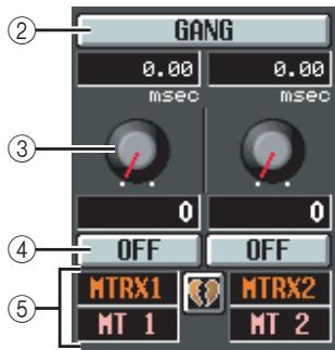
② GANG
This button specifies whether the delay parameters will be linked for adjacent odd-numbered/even-numbered channels. This can be specified independently of pairing. If the GANG button is turned on for channels of differing delay times, turning the delay time knob (③) will change the delay times of both channels while maintaining the difference in their delay time.
③ Delay time knob
This knob sets the delay time of each channel. The box below the knob shows the delay time in the units you selected in (①). The box above the knob always shows the delay time in millisecond units.
④ DELAY ON/OFF
This button switches delay on/off. This is linked for paired channels.
⑤ Channel
This is the number and name of the channel you are editing. Two paired channels are indicated by a heart symbol displayed between them. You can click this symbol to enable/disable pairing.
OUTPUT DCA/GROUP function
DCA GROUP ASSIGN screen
Here you can specify the output channels that will be assigned to DCA groups 7/8. You can use DCA faders 7/8 to uniformly adjust the levels of output channels belonging to the same DCA group.
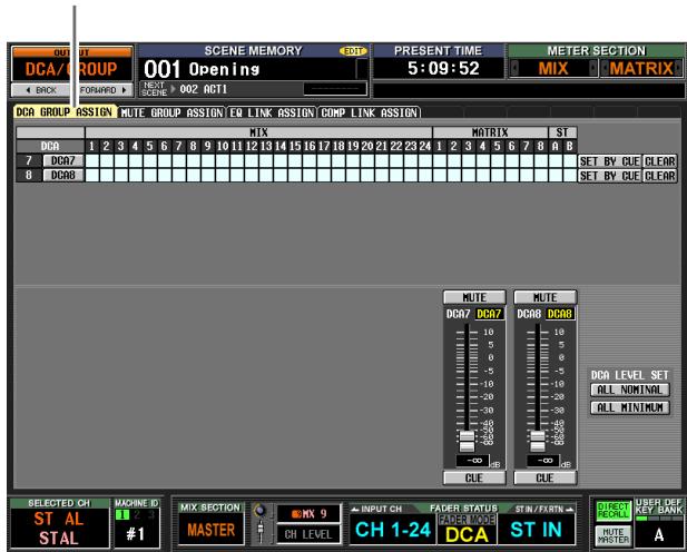
DCA GROUP ASSIGN
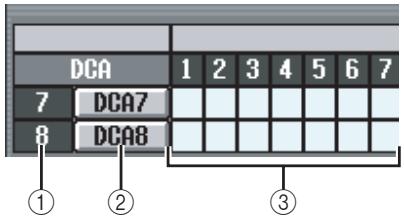
① DCA group
This is the number of the DCA group. The number corresponding to the grid where the cursor is located is highlighted.
② Name
This is the name of the DCA group. You can also click this area to edit the name.
③ Grid
This grid lets you assign output channels (horizontal rows) to DCA groups (vertical columns). Currently-patched grids are indicated by a symbol. Move the cursor to the desired grid and press the [ENTER] key (or click) to set/disable the assignment.
Hint
- You can also assign an output channel to both DCA groups for multiple DCA control.
- DCA groups 1–6 are for input channels only, but DCA groups 7/8 can be used with both input channels and output channels. DCA groups 7/8 allow you to use both types of channel in the identically-numbered group.
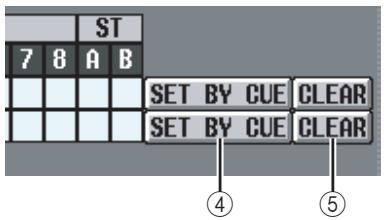
④ SET BY CUE (Assign by [CUE] key)
This specifies whether the [CUE] key will be used to make/cancel DCA group assignments. While the DCA group SET BY CUE button is on, pressing the [CUE] key of a channel that can be assigned to the corresponding group will assign the channel to the group. (Press the [CUE] key once again to cancel the assignment.)
Hint
- The SET BY CUE button can be turned on for only one DCA group. This is automatically turned off when you change screens or turn off the power.
- To turn on SET BY CUE from the panel, press the ASSIGN MODE [DCA] key and then turn on the DCA group 7/8 [CUE] key.
(5) CLEAR
This button clears all output channels assigned to that DCA group.
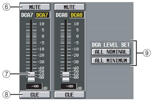
(6) MUTE
These buttons switch muting on/off for DCA groups 7/8. They are linked with DCA [MUTE] keys 7/8 in the DCA strip of the panel.
DCA faders
These faders adjust the levels of DCA groups 7/8. They are linked with DCA faders 7/8 in the DCA strip.
CUE
These buttons cue-monitor DCA groups 7/8. They are linked with DCA [CUE] keys 7/8 in the DCA strip of the panel.
DCA LEVEL SET
Use the following two buttons to operate DCA groups 7/8 together.
ALL NOMINAL
Clicking this button will move DCA faders 7/8 to nominal level (0 dB).
- ALL MINIMUM
Clicking this button will move DCA faders 7/8 to the - dB position.
MUTE GROUP ASSIGN screen
Here you can specify the output channels that will be assigned to mute groups 1-8. Muting can be switched on/off together for channels assigned to the same mute group.
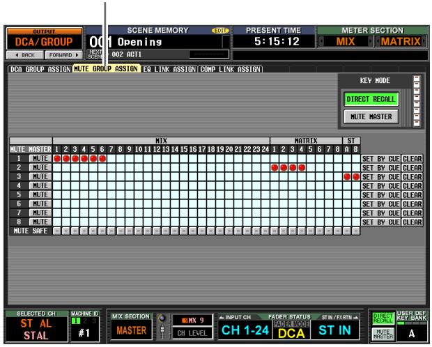
MUTE GROUP ASSIGN
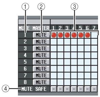
① Mute group
This area shows the mute group number. The number corresponding to the grid where the cursor is located is highlighted.
(2) MUTE (Mute master)
These buttons switch muting on/off for each mute group. These buttons are linked with the SCENE MEMORY [1]-[8] keys of the panel (if the MUTE MASTER button is On in the constantly-shown area at the bottom of the display).
Hint
When you turn muting on, channels belonging to that mute group will behave just as though their panel [ON] key had been turned off; no signal will be output. During this time, the panel [ON] key LED will blink.
③ Grid
This grid lets you assign output channels (horizontal rows) to mute groups (vertical columns). Currently-patched grids are indicated by a symbol. Move the cursor to the desired grid and press the [ENTER] key (or click) to set/cancel the assignment.
(4) MUTE SAFE
These buttons temporarily defeat the muted state of a channel. When a button is displayed as “-”, clicking it will change its display to “ON,” and the corresponding output channel will be excluded from mute groups. Clicking the button once again restores the original state.
Note
Normally, Mute Safe operations can be performed independently of the scene memory.
Hint
Mute groups 1-8 can be used with both input channels and output channels. Both types of channel can exist in the identically-numbered mute group.
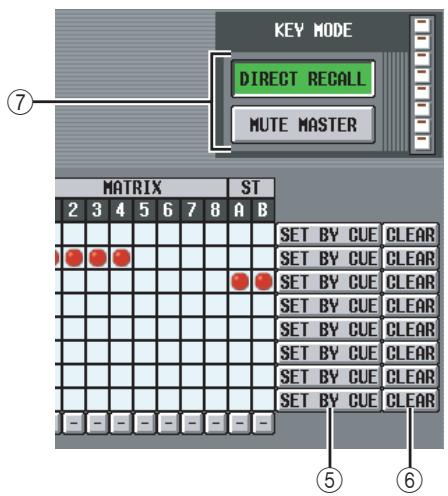
⑤ SET BY CUE (Assign by [CUE] key)
This specifies whether the [CUE] key will be used to make/cancel mute group assignments. While the mute group SET BY CUE button is on, pressing the [CUE] key of a channel that can be assigned to the corresponding group will assign the channel to the group. (Press the [CUE] key once again to cancel the assignment.)
Hint
The SET BY CUE button can be turned on for only one mute group. This is automatically turned off when you change screens or turn off the power.
⑥ CLEAR
This button clears all output channels assigned to that mute group.
⑦ DIRECT RECALL/MUTE MASTER
This is the same function as the DIRECT RECALL/ MUTE MASTER buttons located at the bottom of the display ( p.165).
EQ LINK ASSIGN screen
Here you can specify the output channels that will be assigned to EQ link groups A-H. EQ parameters are linked for channels belonging to the same group.
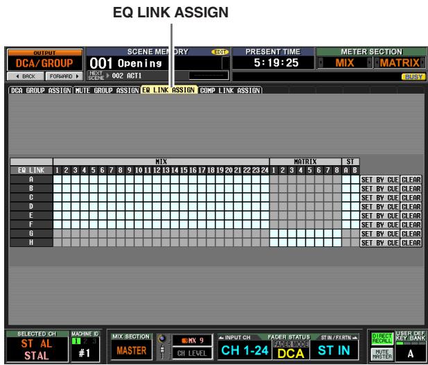
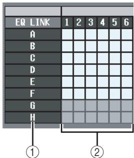
① EQ link group
These are the EQ link group numbers. The number corresponding to the grid where the cursor is located is highlighted.
② Grid
This grid lets you assign output channels (horizontal rows) to EQ link groups (vertical columns). Currently-patched grids are indicated by a symbol. Move the cursor to the desired grid and press the [ENTER] key (or click) to set/cancel the assignment.
Hint
- The MIX channels and STEREO A/B channels can be assigned only to EQ link groups A - F , and MATRIX channels can be assigned only to EQ link groups G / H .
- Grey areas in the grid indicate combinations that cannot be assigned.
- Input channels and output channels use separate EQ link groups. Output channels use groups A-H , and input channels use groups 1-8.
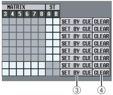
③ SET BY CUE (Assign by [CUE] key)
This specifies whether the [CUE] key will be used to make/cancel EQ link group assignments. While the EQ link group SET BY CUE button is on, pressing the [CUE] key of a channel that can be assigned to the corresponding group will assign the channel to the group. (Press the [CUE] key once again to cancel the assignment.)
Hint
The SET BY CUE button can be turned on for only one EQ link group. This is automatically turned off when you change screens or turn off the power.
(4) CLEAR
This button clears all output channels assigned to that EQ link group.
COMP LINK ASSIGN (Compressor link assign) screen
Here you can specify the output channels that will be assigned to compressor link groups A-H. Compressor parameters are linked for channels belonging to the same group.
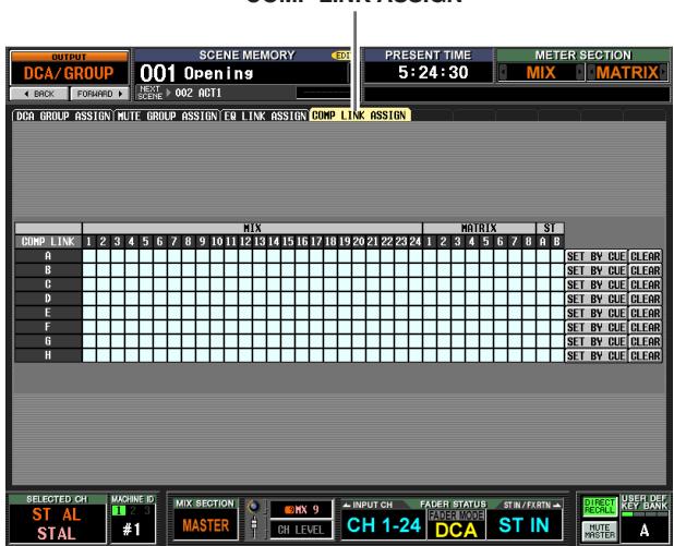
COMP LINK ASSIGN
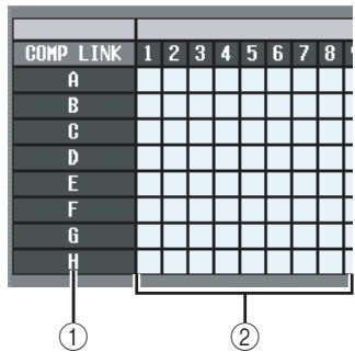
① Compressor link group
This area shows the compressor link group number. The number corresponding to the grid where the compressor is located is highlighted.
② Grid
This grid lets you assign output channels (horizontal rows) to compressor link groups (vertical columns). Currently-patched grids are indicated by a symbol. Move the cursor to the desired grid and press the [ENTER] key (or click) to set/cancel the assignment.
Hint
Input channels and output channels use separate compressor link groups. Output channels use groups A-H , and input channels use groups 1-8.
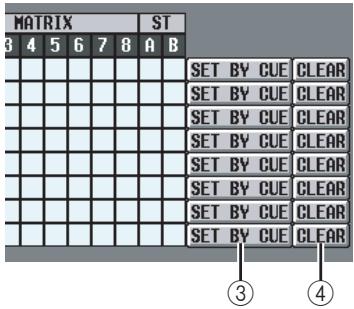
③ SET BY CUE (Assign by [CUE] key)
This specifies whether the [CUE] key will be used to make/cancel compressor link group assignments. While the compressor link group SET BY CUE button is on, pressing the [CUE] key of a channel that can be assigned to the corresponding group will assign the channel to the group. (Press the [CUE] key once again to cancel the assignment.)
Hint
The SET BY CUE button can be turned on for only one compressor link group. This is automatically turned off when you change screens or turn off the power.
(4) CLEAR
This button clears all output channels assigned to that compressor link group.
MATRIX/ST function
MATRIX/ST ROUTING screen
Here you can send the signal from MIX channels and STEREO A/B channels to the STEREO bus or the desired MATRIX bus.
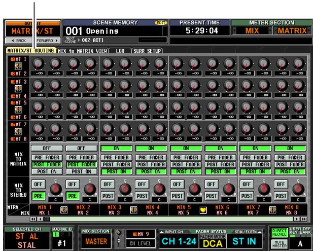
MATRIX/ST ROUTING
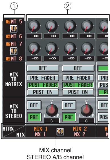
① MATRIX bus
This is the number of the MATRIX bus to which the signal is sent. Paired MATRIX channels are indicated by a heart symbol displayed between them. You can click this symbol to enable/disable pairing.
② Send level
These knobs specify the send level of each signal that is sent from the MIX channel or STEREO A/B channel (vertical column) to the MATRIX buses (horizontal row).
The knobs shown in this area will depend on how the MATRIX channels are paired.
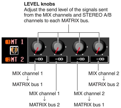
If the MATRIX channels are used individually

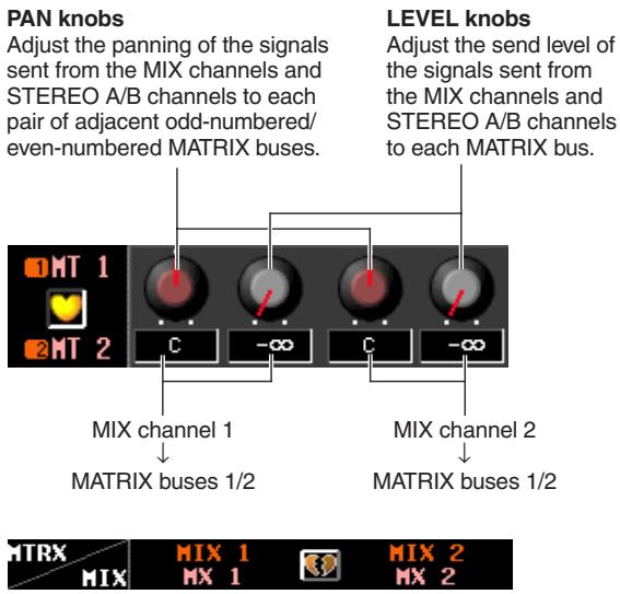
If the MATRIX channels are paired
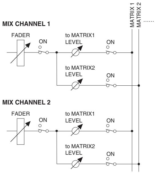
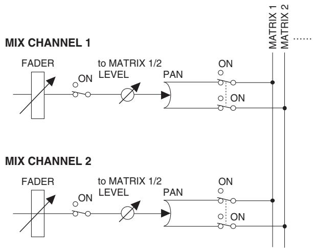
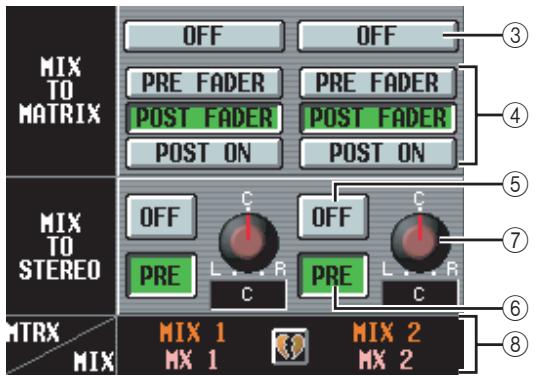
(3) MIX TO MATRIX ON/OFF
This button is an on/off switch for the signal sent from each MIX channel or STEREO A/B channel to the MATRIX buses. If this button is off, no signal will be sent from that channel to the MATRIX buses.
(4) PRE FADER/POST FADER/POST ON
These buttons select the position from which the signal is sent from the MIX channel or STEREO A/B channel to the MATRIX buses, from the following choices.
| PRE FADER | Immediately before the fader |
| POST FADER | Immediately after the fader |
| POST ON | Immediately after the MIX [ON] key / STE-REO [ON] key |
This parameter applies to the signal sent from the corresponding channel to all MATRIX buses.
⑤ MIX TO STEREO ON/OFF
This button is an on/off switch for the signal sent from each MIX channel to the STEREO bus. If this button is off, no signal will be sent from that channel to the STEREO bus.
(6) PRE/POST (Pre-on/Post-on)
This button selects the position from which the signal is sent from the MIX channel to the STEREO bus, from the following choices.
| PRE | Immediately before the MIX [ON] key (immediately after the fader) |
| POST | Immediately after the MIX [ON] key |
⑦ PAN (MIX→STEREO pan)
This knob specifies the panning of the signal sent from the MIX channel to the STEREO bus. If a MIX channel is selected in the SELECTED CHANNEL section, the STEREO [PAN] encoder is linked with this knob.
Hint
If the source is a STEREO A/B channel, parameters 5-7 are not displayed.
⑧ MIX channel, STEREO A/B channel
This area indicates the MIX channel or STEREO A/B channel from which the signal is being sent. Paired MIX channels are indicated by a heart symbol displayed between them. You can click this symbol to enable/disable pairing.
MIX to MATRIX VIEW screen
This screen lists the signals sent from the MIX channels to the MATRIX buses. You can also edit the settings from within this screen.
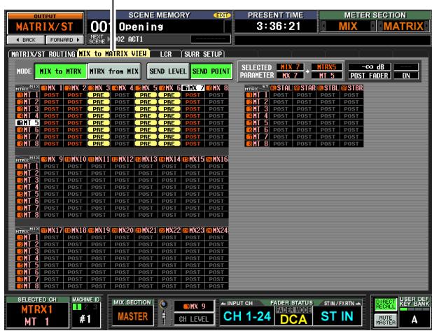
MIX to MATRIX VIEW
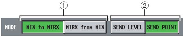
① MIX to MTRX/MTRX from MIX
Select one of the following two types of screen display.
□ When the MIX to MTRX button is on
You can view the status of the signals sent from a specific MIX channel or STEREO A/B channel to all MATRIX buses.
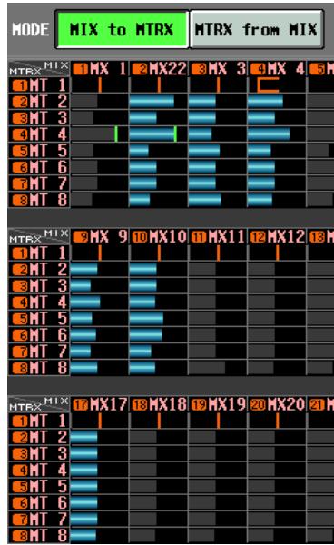
□ When the MTRX from MIX button is on
You can view the status of the signals sent from all MIX channels or STEREO A/B channels to a specific MATRIX bus.
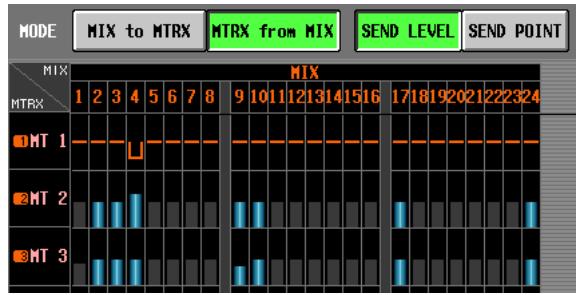
② SEND LEVEL/SEND POINT
Select one of the following two parameters to view in the grid.
□ When the SEND LEVEL button is on
The send levels sent from the MIX channels or STE-REO A/B channels to the MATRIX buses will be shown as a bar graph in each grid. Channels for which the signal sent to the MATRIX bus is turned off are shown by gray bars, and channels for which the signal is turned on are shown by blue bars.
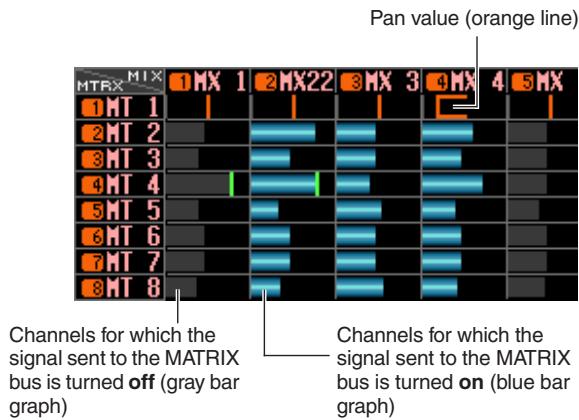
To edit the send level, move the cursor to the grid where the MIX or STEREO A/B channel (vertical column) intersects the MATRIX bus (horizontal row), and turn the [DATA] encoder.
To switch the signal sent from a specific MIX or STE-REO A/B channel to the MATRIX buses on/off, move the cursor to the vertical column for that channel, and press the [ENTER] key.
Hint
- If the send level is set above nominal (0 dB), a red line indicating nominal level is displayed.
- If the send-destination MATRIX channel is paired, the grid for the odd-numbered MATRIX bus will show an orange line indicating the pan value instead of a bar graph. (In MTRX from MIX mode, upward indicates R , and downward indicates L .)
If the SEND LEVEL button is on, you can select a desired grid and copy its send level (pan) value to other channels (horizontal direction) or to other MATRIX buses (vertical direction), or switch all grids on/off simultaneously.
To do so, move the cursor to the desired grid; then hold down the [SHIFT] key and press the [ENTER] key. (Alternatively, hold down the [SHIFT] key and click the desired grid.) When the JOB SELECT win
dow appears, select one of the following choices to copy, and click the OK button.
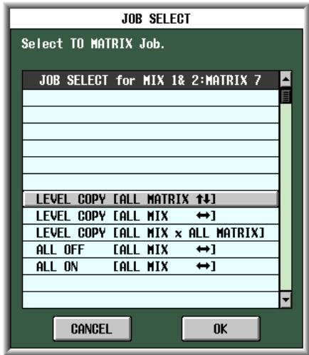
LEVEL COPY [ALL MATRIX↑↓]
Copy the send level (pan) value of the selected grid to all send level (pan) settings of the corresponding MIX (or STEREO A/B) channel in the vertical direction of the grid.
Note
If the selected grid is a send level, only the send levels will be copied. If the selected grid is a pan value, only the pan values will be copied.
LEVEL COPY [ALL MIX ]
Copy the send level (pan) value of the selected grid to all send level (pan) settings of the corresponding MATRIX bus in the horizontal direction of the grid.
LEVEL COPY [ALL MIX x ALL MATRIX]
Copy the send level (pan) value of the selected grid to the send level (pan) settings of all MIX (and STEREO A/B) channels and MATRIX buses.
ALL ON [ALL MIX ]
Turn on the signals sent from all channels (MIX, STEREO A/B) to the corresponding MATRIX bus.
ALL OFF [ALL MIX ]
Turn off the signals sent from all channels (MIX, STEREO A/B) to the corresponding MATRIX bus.
□ When the SEND POINT button is on
The grid will show the position from which the signal is sent from the MIX channels or STEREO A/B channels to the MATRIX buses.
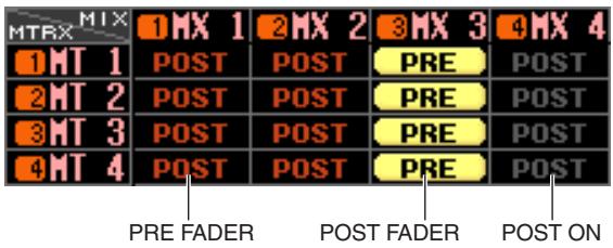
Each indication has the following significance.
PRE (yellow) .. PRE FADER (immediately before the fader)
POST (gray) . POST FADER (immediately after the fader)
POST (red) . POST ON (immediately after the [ON] key)
To change the position from which the signal is sent, move the cursor to the vertical column for the desired channel, and press the [ENTER] key, click, or turn the [DATA] encoder. (The position of all signals sent from that channel to all MATRIX buses will change simultaneously.)
If the SEND POINT button is on, the send position for all grid locations can be changed simultaneously. To do so, hold down the [SHIFT] key and click the desired grid. (Alternatively, move the cursor to the desired grid; then hold down the [SHIFT] key and press the [ENTER] key.) When the JOB SELECT window appears, select one of the following choices, and click the OK button.
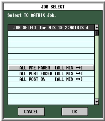
ALL PRE FADER [ALL MIX ]
All grids will be set to PRE FADER.
ALL POST FADER [ALL MIX ]
All grids will be set to POST FADER.
ALL POST ON [ALL MIX ]
All grids will be set to POST ON.
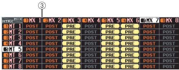
③ Grid
The grid shows various settings for the signals sent from the MIX or STEREO A/B channels (vertical columns) to the MATRIX buses (horizontal rows). The red lines shown in the upward, downward, left, and right directions indicate the channel (MIX or STEREO A/B) and MATRIX bus corresponding to the grid where the cursor is located.
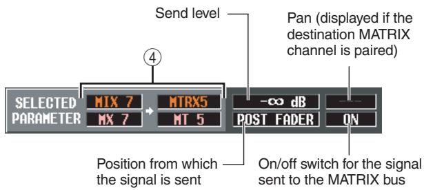
(4) SELECTED PARAMETER (currently selected parameter)
This area indicates the channel (MIX or STEREO A/B) and MATRIX bus corresponding to the grid where the cursor is currently located. The four boxes at right indicate the values for the grid where the cursor is currently located.
LCR screen
Here you can make settings for LCR mode, which allows three-channel playback by adding a CENTER channel to the L/R channels of the STEREO bus. This function can be used only with MIX channels.
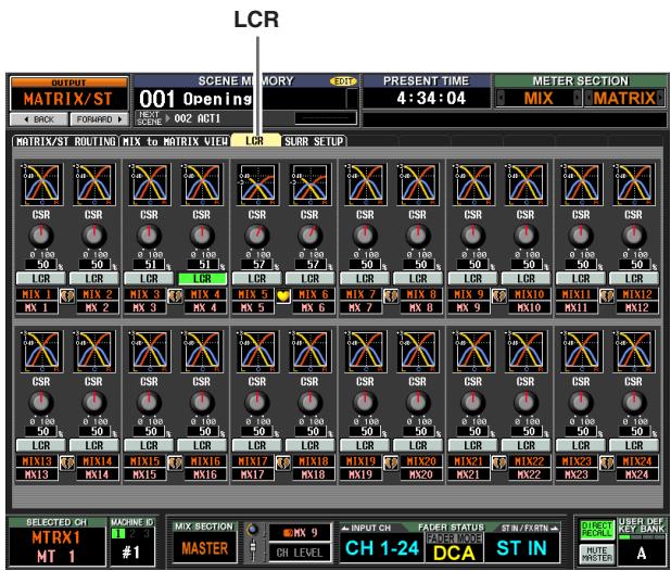
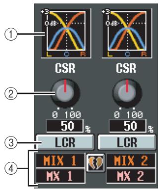
① Response graph
These graphs indicate the approximate LCR response for each MIX channel. The graph will change as the CSR knob (②) is edited.
② CSR (Center Side Ratio)
This knob adjusts the proportional level of the CEN-TER channel relative to the L/R channels. The range is 0 - 100% .
If the CSR knob is set to 0% , turning the PAN knob in the MIX TO STEREO area of the MATRIX/ST ROUTING screen (or the [PAN] encoder in the SELECTED CHANNEL section) will change the signal levels of the L/R channels as shown below.
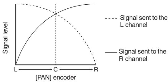
In this case, MIX TO STEREO PAN will operate as a conventional PAN control, and no signal will be sent to the CENTER channel.
If CSR is set to 100% , turning the PAN knob ([PAN] encoder) will change the signal levels of the L/R channels as shown below.
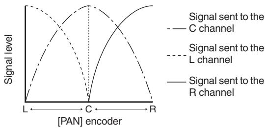
When the PAN knob ([PAN] encoder) is in the center position, the signal level of the CENTER channel will be at maximum, and no signal will be sent to the L/R channels.
③ LCR (LCR mode on/off)
For each MIX channel, this turns LCR mode on/off. For channels where LCR mode is turned on, the PAN knob in the MIX TO STEREO area of the MATRIX/ST ROUTING screen can be used to simultaneously control the levels of the L/R channels and the CENTER channel.
If you have selected a MIX channel for which LCR is on, you can also use the [PAN] encoder in the SELECTED CHANNEL section of the top panel. In this case, the peripheral LEDs will change as follows when you operate the [PAN] encoder.
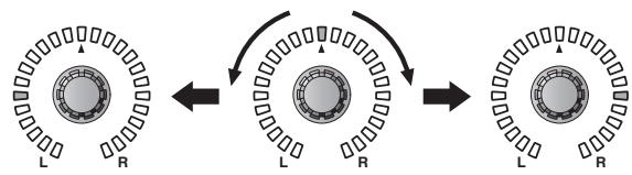
- When LCR = off
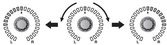
- When LCR = on
Note
In order to use the LCR function, the USE AS CENTER BUS button must be turned On in the MIXER SETUP screen (SYS/W.CLOCK function) ( p.222) . Be aware that when this button is on, the CENTER channel signal is not sent to the STEREO B bus, and will not play back appropriately. (In this case, the STEREO B bus is sent the same signal as the STE-REO A bus.)
④ MIX channel
This is the number and name of the MIX channel you are editing. Paired MIX channels are indicated by a heart symbol displayed at the right. You can click this symbol to enable/disable pairing. The values of parameters ②-③ are linked for paired channels.
Hint
- The master level of the CENTER channel is controlled by the STEREO B channel fader. You can also use the STE-REO B channel EQ and compressor to process the signal.
- Use either one of the output jacks patched to the STEREO B channel as the output jack for the CENTER channel. (When the USE AS CENTER BUS button is On in the MIXER SETUP screen, the L/R channels of the STEREO B bus output the same signal.)
- By selecting LCR as the monitor source, you can monitor the LCR signal from the MONITOR OUT jacks L/C/R.
SURR SETUP screen
Here you can make various settings related to surround functionality, such as selecting the surround mode, and assigning MIX buses to surround channels.
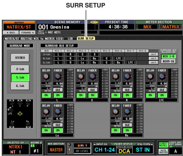
① SURROUND MODE
Choose one of the following as the surround mode when using the Surround Pan function (p.142). This is the same as the SURROUND MODE in the MIXER SETUP screen (SYS/W.CLOCK function). The graphic below the buttons will change according to the mode you select.
STEREO
This is conventional stereomode.
3-1ch
This mode uses four channels: L (front left), C (front center), R (front right), and S (surround).
5.1ch
This mode uses six channels: L (front left), C (front center), R (front right), Ls (rear left), Rs (rear right), and LFE (subwoofer).
6.1ch
This mode uses seven channels: 5.1ch with the addition of Bs (rear center).
Hint
If 3-1ch, 5.1ch, or 6.1 ch is selected as the surround mode, MIX buses 1-8 or 9-16 are used as surround buses, starting with the earlier-numbered buses. (Buses not used as surround buses can be used as conventional buses.) These MIX buses cannot be used as conventional bus outputs until you return to stereo mode.
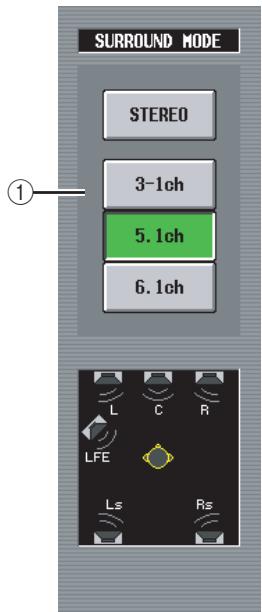
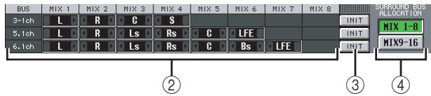
② Bus assignments
This area indicates the surround channels assigned to the MIX buses that are being used as surround buses. You can edit these settings by clicking the 1 / 2 buttons at the left and right.
When you change the surround channel assignment, the MIX bus whose channel assignment you changed will be exchanged with the MIX bus that had been previously assigned to that channel.
Note
The MIX buses used are fixed for each surround mode. For surround mode 3-1, MIX buses 1-4 or 9-13 can be used. For surround mode 5.1, MIX buses 1-6 or 9-14 can be used. For surround mode 6.1, MIX buses 1-7 or 9-15 can be used. Other MIX buses can be used as conventional MIX buses. However in the case of 6.1, MIX bus 8 or MIX bus 16 are always handled as FIXED buses.
③ INIT (Initialize)
For each surround mode, this restores the surround channel assignments to the MIX buses to their initial state.
Select either MIX buses 1-8 or 9-16 as the range of MIX buses used as surround buses.
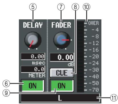
⑤ DELAY
This specifies the delay time for each surround channel in a range of 0-1000 msec. The current value is shown by the two boxes below the knob. (The upper box shows the delay time in millisecond units, and the lower box shows the delay time in the units selected in the MIX 1-24 screen of the OUT DELAY function.)
⑥ DELAY ON/OFF
Turns the delay on/off for each surround channel.
⑦ FADER (Fader level)
Adjusts the level of the signal sent from the surround channel to the corresponding MIX bus in a range of - to +10 dB. The current value is shown in the box below.
CUE
This button lets you cue-monitor the surround channel. This is linked with the [CUE] key of the corresponding MIX channel.
⑨ ON/OFF (Channel on/off)
Turns the surround channel on/off. This is linked with the MIX [ON] key of the corresponding MIX channel.
⑩ Level meter
Indicates the output level of the surround channel.
⑪ Surround channel
This is the name of the surround channel.
OUTPUT VIEW function
CH VIEW (Channel view) screen
This screen displays the mix parameters of the currently selected MIX channel, MATRIX channel, or STEREO A/B channel. In this screen you can also edit the principal parameters and access other screens.
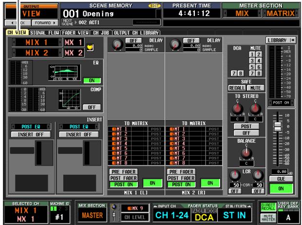
CH VIEW
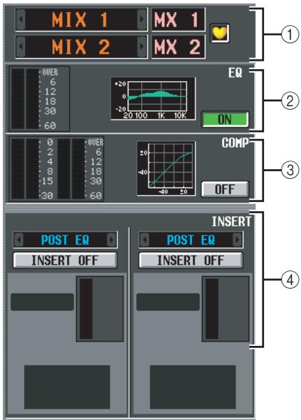
① Channel
This is the number of the channel you are editing. If the corresponding MIX/MATRIX channel is paired (or if a STEREO A/B channel is selected), a heart symbol is displayed at the right. You can click this symbol to enable/disable pairing for the MIX/Matrix channel.
Note
The screen shown above is for when a paired channel is selected. If the selected channel is not paired, the parameters for only one channel are displayed, and pairing-related settings are not displayed.
② EQ
This area shows the post-EQ level, the approximate EQ response, and the EQ on/off status. You can click the EQ ON/OFF button to switch EQ on/off in this screen.
If you click the mini-graph, the EQ PARAM screen for that channel will appear.
③ Compressor
This area shows the amount of gain reduction and the output level of the compressor, a mini-graph showing the approximate response of the compressor, and the compressor on/off status. You can click the COMP ON/OFF button to switch the compressor on/off in this screen. If you click the mini-graph, the COMP PARAM screen for that channel will appear.
④ Insert in
This area indicates the insert point, the insert on/off status, and the type and input level of the port that is patched to insert-in. You can click the INSERT ON/OFF button to switch insertion on/off in this screen. If an internal effect is patched, the effect type and BYPASS button are displayed. If a GEQ module is patched, the GEQ ON/OFF button and a mini-graph showing the GEQ response are displayed.
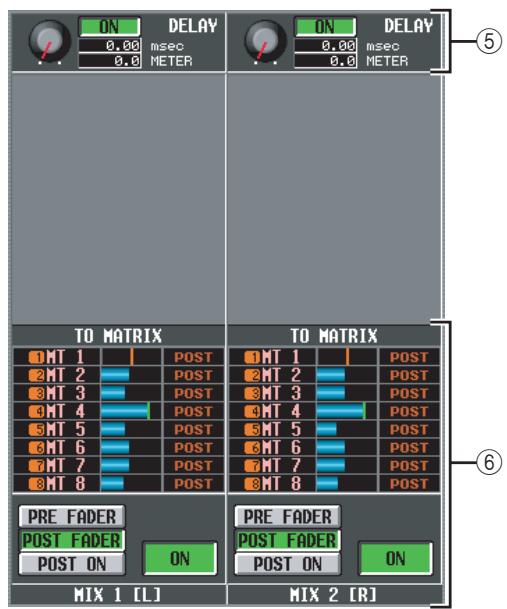
⑤ DELAY
In this area you can view and edit the delay time of the internal delay and its on/off status.
⑥ TO MATRIX (only for MIX channels and STEREO A/B channels)
This area shows the send level, send position, and on/off status of the signals sent from the corresponding MIX channel or STEREO A/B channel to MATRIX buses 1-8. You can also edit the send level, send position, and on/off status in this screen. Here's how to do this.
- To edit the send level of signals sent to the MATRIX bus
Move the cursor to the desired bar graph in the list, and turn the [DATA] encoder.
- To edit the send position of signals sent to the MATRIX bus
Click either the PRE FADER, the POST FADER, or the POST ON button located below.
Alternatively, you can edit the setting by moving the cursor to the PRE or POST indication in the list and pressing the [ENTER] key or turning the [DATA] encoder.
- To switch the signal sent to the MATRIX bus on/off Click the ON/OFF button located below.
You can also switch this on/off by moving the cursor to a bar graph in the list and pressing the [ENTER] key.
The bar graph is colored blue when on, and gray when off.
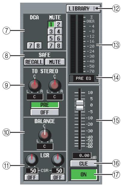
(7) DCA group / Mute group
Here you can assign or cancel DCA group and MUTE group assignments.
(8) RECALL SAFE / MUTE SAFE
Here you can enable or disable Recall Safe and Mute Safe settings.
⑨ TO STEREO (MIX channels only)
Here you can switch the signal sent from a MIX channel to the STEREO bus on/off, and edit its panning and send position (pre-on / post-on) ( p.264).
⑩ BALANCE (only for paired MIX/MATRIX channels and STEREO A/B channels)
This adjusts the left/right volume balance of the signals output from paired MIX channels or STEREO A/B channels.
① LCR (MIX channels only)
Here you can switch LCR mode on/off, and adjust CSR (the level of the CENTER channel relative to the L/R channels) ( p.267).
⑫ LIBRARY
This button accesses the OUTPUT CH LIBRARY screen ( p.275), where you can store/recall library settings for output channels.
13 Level meter
This level meter indicates the output level of the channel.
④ Signal detection point
This is the point at which the signal level shown in the level meter (⑬) is detected (PRE EQ, PRE FADER, POST FADER, POST DELAY, or POST ON). You can edit this setting by clicking the / buttons at the left and right.
15 Fader
This controls the output level of the channel.
⑥ CUE
This button cue-monitors the signal of the channel.
This is linked with the [CUE] key of the corresponding channel.
17 ON/OFF (Channel on/off)
This is an on/off switch for the signal that is output from the channel. This is linked with the [ON] key of that channel.
SIGNAL FLOW screen
This screen shows the signal flow for adjacent odd-numbered/even-numbered MIX/MATRIX channels or for STEREO A/B channels. In this screen you can also edit some of the parameters, and access other screens. You can also determine the location within the signal flow at which clipping occurred.
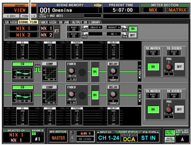
SIGNAL FLOW
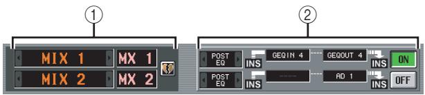
① Channels
These are the numbers and names of the channels you are editing. By clicking the / buttons at left and right, you can switch the display in units of two channels.
If the corresponding MIX/MATRIX channels are paired (or if a STEREO A/B channel is selected), a heart symbol is displayed at the right. You can click this symbol to enable/disable pairing for the MIX/MATRIX channels.
② Insert
This area displays insert-related information for the two selected channels (insert point, the ports patched to insert in/out, and insert on/off status).
Here you can also select the insert point (use the / buttons at left and right), or switch insertion on/off (use the ON/OFF button).
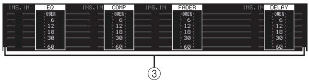
③ Level meters
These meters indicate the levels within the signal flow. Levels are detected at the following locations.
- EQ (immediately before and after the EQ)
- COMP (immediately before and after the compressor)
- FADER (immediately before and after the fader)
- DELAY (immediately before and after the delay)
- INSERT IN (immediately after the insert point)
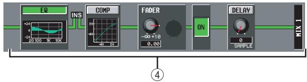
④ Signal flow
This area indicates the signal flow of the selected channel. The following parameters are displayed.
EQ (Equalizer)
This indicates the EQ on/off status and the approximate response curve. You can click the EQ button to switch EQ on/off, or click the mini-graph to access the EQ PARAM screen for the corresponding channel.
COMP (Compressor)
This indicates the compressor on/off status and the approximate response curve. You can click the COMP button to switch the compressor on/off, or click the mini-graph to access the COMP PARAM screen for the corresponding channel.
- FADER
This indicates the output level of the channel. This is linked with the encoder or fader of the corresponding channel.
- ON/OFF (On/off)
Turns the channel on/off. This is linked with the [ON] key of the corresponding channel.
- DELAY
Here you can switch the internal delay on/off and edit the delay time.
Hint
- If insert is enabled, the currently selected insert point is shown in this signal flow.
- If the signal clips, the signal flow (horizontal line) after clipping is displayed in red. If an output is turned off so that the signal does not flow any further, the subsequent flow is displayed in gray. IF PEAK HOLD is on, the flow indication will stay red if clipping occurs even once, making it easier to see that clipping has occurred.
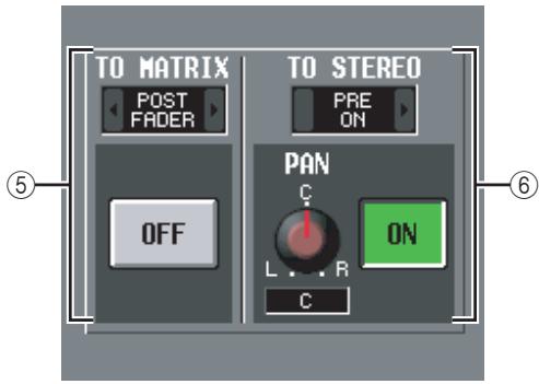
⑤ TO MATRIX (only for MIX channels and STEREO A/B channels)
This area shows the on/off status of the signal sent from the MIX channel or STEREO A/B channel to the MATRIX buses, and the point from which the signal is sent.
⑥ TO STEREO (MIX channels only)
This area shows the pan, the send position, and the on/off status of the signal sent from the MIX channel to the STEREO bus.
FADER VIEW screen
This screen shows the on/off status, level, and cue monitor status of the output channels and DCA groups.
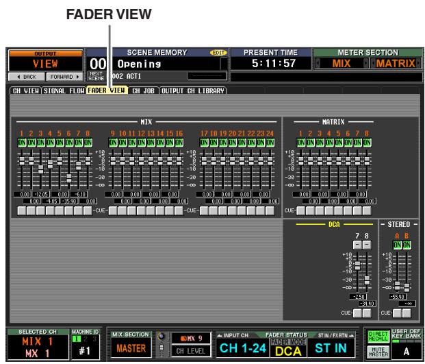
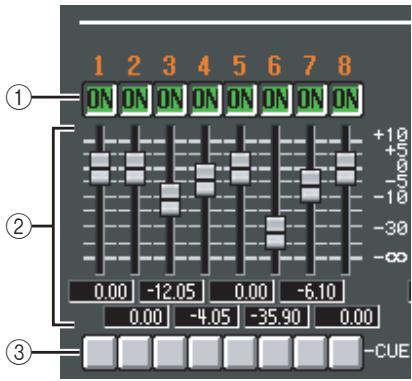
① ON/OFF (On/off)
Here you can switch output channels on/off, and switch DCA group muting on/off. These settings are linked with the [ON] keys of the corresponding channels and the [MUTE] keys of the DCA groups.
② Level
Here you can adjust the level of the output channels and DCA groups. The current value is shown in the box immediately below. These are linked with the encoder or fader of the corresponding channel or DCA group.
③ Cue
Here you can switch cue monitoring on/off for output channels and DCA groups. These are linked with the [CUE] key of the corresponding channel or DCA group.
CH JOB (Channel job) screen
In this screen you can copy the desired parameter(s) from the selected output channel into a memory buffer, and paste the same type of channel (you may select more than one paste-destination).
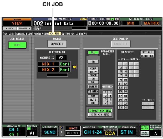
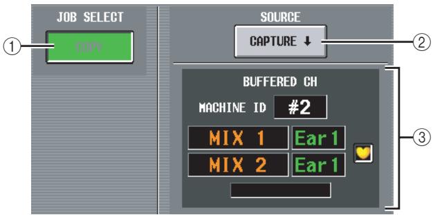
① JOB SELECT
COPY
The copy-source channel will remain; its parameters will be copied to another channel.
Note
You cannot turn off the COPY button.
(2) CAPTURE
When you click this button, the settings of the currently selected channel will be copied to a temporary memory buffer.
If the corresponding MIX/MATRIX channel is paired (or if a STEREO A/B channel is selected), a heart symbol is displayed at the right.
③ BUFFERED CH (Channel in the buffer)
This shows the channel that is currently copied into buffer memory.
Note
- The same buffer memory is used to copy channel settings for both input channels and output channels.
- If input channel settings have been copied to the buffer memory, a message of "TYPE CONFLICT!" is displayed below, and you cannot paste to an output channel.
- The contents of the buffer memory are erased when the PM5D is powered-off.
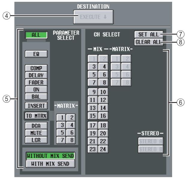
(4) EXECUTE
When you click this button, the specified parameters will be copied from buffer memory to the specified paste-destination channel.
If an input channel is copied to buffer memory, or if no paste-destination has been specified, this is grayed-out and the Paste operation is unavailable.
(5) PARAMETER SELECT
Here you can select the parameter(s) that will be pasted. You can select the following parameters.
| ALL | All parameters |
| EQ | EQ function settings |
| COMP | COMP function settings |
| DELAY | DELAY function settings |
| FADER | Fader level |
| ON | CH [ON] key on/off status |
| BAL | Balance settings |
| INSERT | Insert on/off status and insert point |
| TO MTRX | Send level to the desired MATRIX bus(es) |
| DCA | Associated DCA group |
| MUTE | Associated mute group |
| LCR | LCR screen settings |
| WITHOUT MIX SEND/ WITH MIX SEND | Selects whether the send level sent from input channels to the selected MIX bus will be included (WITH...) or will not be included (WITHOUT...) in the pasted data. |
If the TO MTRX button is on, you can use the MATRIX buttons (1-8) to select the applicable MATRIX buses.
CH SELECT (Channel selection)
Here you can select the paste-destination channel(s). You can only select channels of the same type as the copy-source.
Hint
If the copy-source MIX/MATRIX channel is paired, the odd-numbered channel is copied to the odd-numbered channel(s), and the even-numbered channel is copied to the even-numbered channel(s).
⑦ SET ALL
Specifies the paste-destination as all channels of the same type as the copy-source.
(8) CLEAR ALL
De-selects all channels.
OUTPUT CH LIBRARY screen
Here you can recall, store, rename, or delete items in the output channel library.
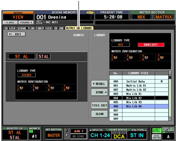
OUTPUT CH LIBRARY
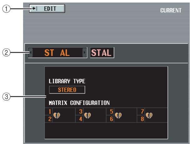
(1) EDIT
When you click this button, the CH VIEW screen (OUTPUT CH VIEW screen) for the currently selected output channel will appear.
② Channel
This is the number and name of the channel you will store or recall.
Note
- Channel library store/recall operations are performed in units of one channel.
- If the channel selected by the [SEL] key is paired (or if a STEREO A/B channel is selected), the operation will apply to only one of the currently selected channels (in the case of STEREO A/B, only the L or the R channel).
- When you recall a channel library item into one of a pair of MIX/MATRIX channels (or into L or R of the STEREO A/B channel), any linked parameters will be copied to the other channel.
③ LIBRARY TYPE (Channel type)
Indicates the type of the currently selected channel. If a MIX or STEREO A/B channel is selected, the pairing configuration of MATRIX buses 1-8 is shown immediately below.
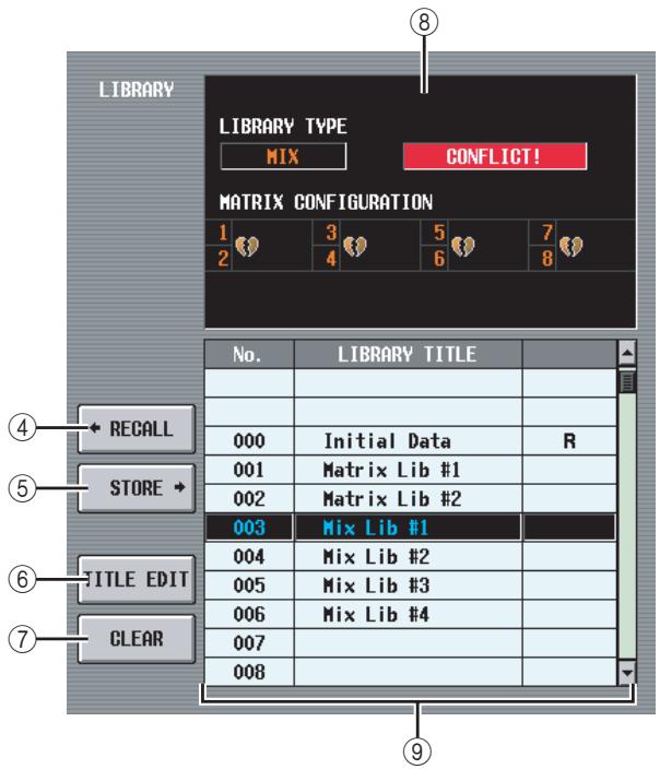
(4) RECALL
Recalls the channel library item selected in the list into memory.
If the channel selected in (①) is of a different type than the channel selected in the list, this button is grayed-out and the Recall operation is unavailable. (However, Initial Data can be recalled to any output channel.)
⑤ STORE
Stores the settings of the currently selected output channel into the location selected in the list. When you click this button a window will appear, allowing you to name and save the settings.
(6) TITLE EDIT
Edits the title of the library item selected in the list. When you click this button a window will appear, allowing you to edit the title.
(7) CLEAR
Deletes the library item selected in the list. When you click this button, a confirmation message will appear.
Note
Library items with an "R" displayed in the right column of the list are read-only. Read-only items cannot be stored, renamed, or deleted.
(8) LIBRARY TYPE
Displays the type of channel for the library item selected in the list. If the channel selected in (①) is of a different type than the channel selected in the list, a message of "CONFLICT!" is displayed at the right and the Recall operation is unavailable.
If a MIX or STEREO A/B channel is selected, the pairing configuration of MATRIX buses 1-8 is shown immediately below.
⑨ Library list
Use the scroll bar to select the library item on which you want to perform an operation. The selected library item will move to the center, and will be highlighted.
Input functions
INPUT PATCH function
INPUT PATCH screen
Here you can assign input ports (INPUT jacks, ST IN jacks, 2TR IN DIGITAL/ANALOG jacks, input channels of slots, outputs of internal effects) to input channels.
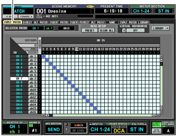
INPUT PATCH
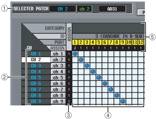
① SELECTED PATCH
This indicates the name and number of the input channel at which the cursor is located, and the input port.
CH (Input channel)
This is the number and name of the input channel (input channel, ST IN channel, FX RTN channel) assigned to the input port. The channel number at which the cursor is located will be highlighted. If you click the name, a window will open allowing you to assign a name to the channel.
③ ASSIGN
For each channel, this indicates the number (1 or 0) of input ports currently assigned.
④ Grid
This grid lets you patch input ports (horizontal rows) to input channels (vertical columns). Currently-patched grids are indicated by a symbol. By clicking a grid location you can set/cancel patching.
The red lines at the left and top indicate the grid location to which you move the cursor.
Hint
- If PATCH CONFIRMATION is turned on in the PREFERENCE 1 screen (UTILITY function), a confirmation message will appear each time you attempt to change a patch setting. If STEAL PATCH CONFIRMATION is turned on, a confirmation message will also appear when you attempt to make patch settings that would cause an existing patch to be modified.
To move the cursor location rapidly in or out of the grid, hold down the [SHIFT] key and press the CURSOR []/[]/[] /[▼] keys. - To move rapidly to left or right inside the grid, turn the [DATA] encoder. To move up or down, hold down the [SHIFT] key and turn the [DATA] encoder.
Note
You can patch multiple input channels to a single input port, but you cannot patch multiple input ports to a single input channel.
⑤ Input port
From the top, this area indicates the type of input port, the ID number, the input channel number, and the number of input channels assigned. The following types of input port can be selected.
| AD IN | INPUT jacks 1–48 |
| AD STIN | L/R channels of ST IN jacks 1–4 |
| SLOT IN | Input channels of an I/O card installed in slots 1–4 |
| FX OUT | L/R outputs of internal effects 1–8 |
| 2TR IN | L/R channels of 2TR IN DIGITAL jacks 1–3 and 2TR IN ANALOG jacks 1/2 |
Hint
- The port number is grayed-out for ports that are currently unavailable.
- If the CASCADE connector is being used as a SLOT IN port, the port number of the CASCADE connector is displayed in yellow instead of the SLOT IN port number.
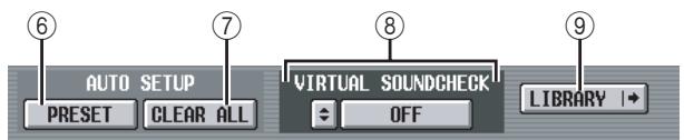
(6) PRESET
This button resets the input port input channel assignments to the following default settings.
| Channel | Input port |
| Input channels 1–48 | AD IN 1–48 |
| ST IN channels 1–4 L/R | AD STIN L/R |
| FX RTN channels 1–4 L/R | FX OUT 1–4 L/R |
(7) CLEAR ALL
This button clears all assignments of input ports to input channels.
(8) VIRTUAL SOUNDCHECK
Here you can make settings for the virtual soundcheck function, which temporarily switches the input patching. For details, refer to the explanation of the SYS/ W.CLOCK function MIXER SETUP screen ( p.221).
⑨ LIBRARY
This button accesses the INPUT PATCH LIBRARY screen ( p.283), where you can store/recall input channel patch library settings.
DIRECT OUT PATCH screen
Here you can patch an input channel to an output port so that the input signal will be output directly from that port.
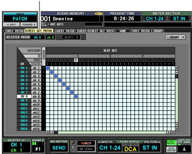
DIRECT OUT PATCH
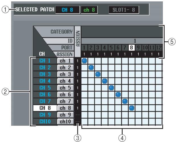
① SELECTED PATCH
This indicates the name and number of the input channel at which the cursor is located, and the output port.
CH (Input channel)
This is the number and name of the input channel (input channel, ST IN channel) for assignment to an output port. The channel number at which the cursor is located will be highlighted. If you click the name, a window will open allowing you to assign a name to the channel.
③ ASSIGN
For each channel, this indicates the number of output ports that are currently assigned.
④ Grid
This grid lets you patch input channels (vertical columns) to output ports (horizontal rows). Currently-patched grids are indicated by a symbol. By clicking a grid location you can set/cancel patching.
The red lines at the left and top indicate the grid location to which you move the cursor.
Hint
Operations in the grid are the same for all of the patching screens. For details, refer to the Hint on p.277.
⑤ Output port
From the top, this area indicates the type of output port, the ID number, the output channel number, and the number of input channels assigned. The following types of output port can be selected.
| SLOT OUT | Output channels of an I/O card installed in slots 1–4 |
| 2TR OUT | L/R channels of 2TR OUT DIGITAL jacks 1–3 |
Hint
- The port number is grayed-out for ports that are currently unavailable.
- For SLOT OUT ports that are also being output to the CASCADE connector, the port number of the CASCADE connector is displayed in yellow instead of the SLOT OUT port number.
(6) LIBRARY button
This button accesses the INPUT PATCH LIBRARY screen ( p.283), where you can store/recall input channel patch library settings.
Note
To enable direct output from the selected port, you will need to make settings in the INSERT/DIRECT OUT POINT screen (INPUT PATCH function) to turn on direct output for the corresponding input channel ( p.281) .
INSERT PATCH screen
In this screen you can patch the input/output ports by which external devices will be inserted into each input channel. Select the output port in the left side of the screen, and the input port in the right side of the screen.
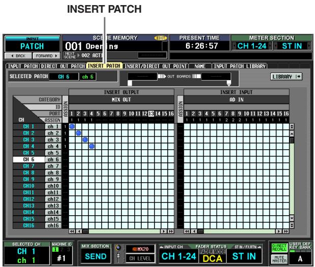

① SELECTED PATCH
This indicates the number and name of the input channel at which the cursor is located in the grid.
② Insert in/out
This indicates the input/output ports that are patched as insert in/out for the input channel at which the cursor is located.
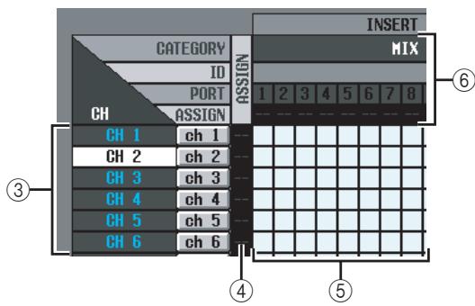
③ CH (Input channel)
This area shows the number and name of each input channel (input channel, ST IN channel L/R). The channel number at which the cursor is located will be highlighted. If you click the name, a window will open allowing you to assign a name to the channel.
④ ASSIGN
For each input channel, this indicates the number of output ports that are currently assigned as insert-out.
⑤ Grid
For each input channel (vertical column), this grid lets you can patch one or more output ports (horizontal row) to be used as insert-outs. Currently-patched grids are indicated by a symbol.
By clicking a grid location you can set/cancel patching. The red lines at the left and top indicate the grid location to which you move the cursor.
Hint
Operations in the grid are the same for all of the patching screens. For details, refer to the Hint on p.277.
⑥ Output port
From the top, this area indicates the type of output port, the ID number, the output channel number, and the number of input channels assigned. The following types of output port can be patched as insert-out.
| MIX OUT | MIX OUT jacks 1–24 |
| SLOT OUT | Output channels of an I/O card installed in slots 1–4 |
| FX IN | L/R inputs of internal effects 1–8 |
| GEQ IN | Inputs of GEQ modules 1–20 |
| 2TR OUT | L/R channels of 2TR OUT DIGITAL jacks 1–3 |
Hint
- The port number is grayed-out for ports that are currently unavailable.
- For SLOT OUT ports that are also being output to the CASCADE connector, the port number of the CASCADE connector is displayed in yellow instead of the SLOT OUT port number.
- If you select GEQ IN as an insert-out, the output of the same GEQ module will automatically be selected as the insert-in.
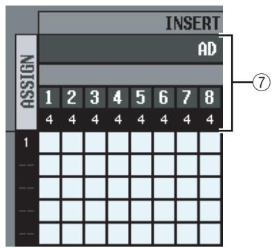
⑦ Input port
From the top, this area indicates the type of input port, the ID number, L/R, the input channel number, and the total number of input channels (including insert-in) that are patched to each input port. You can select the following input ports.
| AD IN | INPUT jacks 1-48 |
| AD ST IN | ST IN jacks 1-4 L/R |
| SLOT IN | Input channels of an I/O card installed in slots 1-4 |
| FX OUT | L/R outputs of internal effects 1-8 |
| GEQ OUT | Outputs of GEQ modules 1-20 |
| 2TR IN | L/R channels of 2TR IN DIGITAL jacks 1-3 or 2TR IN ANALOG jacks 1/2 |
(8) LIBRARY button
This button accesses the INPUT PATCH LIBRARY screen ( p.283), where you can store/recall input channel patch library settings.
Note
To enable the insert ins/outs that you assigned to input channels in this screen, you need to turn Insert on for the corresponding input channel in the INSERT/DIRECT OUT POINT screen (INPUT PATCH function) ( p.281) . However, insertion is automatically enabled if you assigned insert in/out to a GEQ.
Hint
When operating from the panel, you can move the cursor from the right side of the screen to the left side (or vice versa) by holding down the [SHIFT] key and using the CURSOR [▲]/[▶] keys.
INSERT/DIRECT OUT POINT screen
For each input channel, you can specify the point at which insert in/out will be patched, and the point from which direct output will be taken. Here you can also switch Insert or Direct Output on/off.
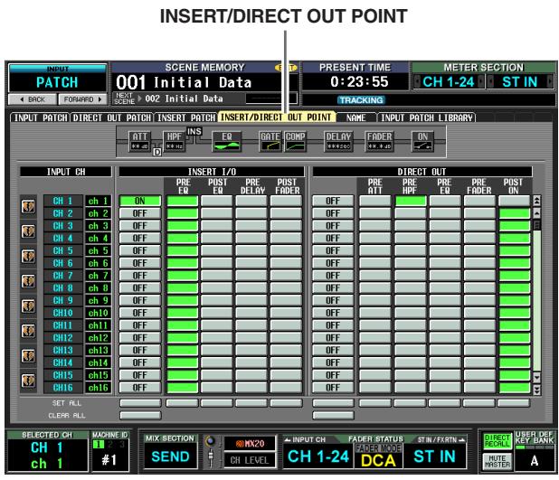
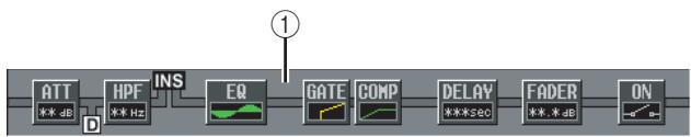
① Insert view
When you move the cursor to an insert I/O point (4), the insert and direct output locations for that input channel will be shown graphically.
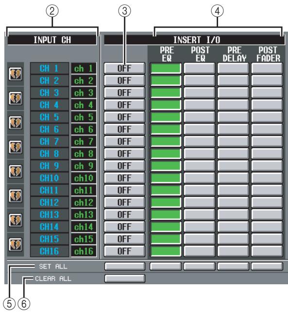
② INPUT CH (Input channel)
This is the number of the input channel you are editing. Two paired channels are indicated by a heart symbol shown at the left; settings ③-⑥ will be linked for these channels. You can click this symbol to enable/ disable pairing.
(3) INSERT ON/OFF
This button switches insert on/off for each channel. This is linked for two paired channels.
Be aware that if you turn on this button when either insert-in or insert-out are unpatched, the signal will no longer be output from the corresponding input channel.
(4) INSERT I/O (Insert I/O point)
Here you can select one of the following as the insertin/out location for each channel.
Note
| PRE EQ | Immediately before the EQ |
| POST EQ | Immediately after the EQ |
| PRE DELAY | Immediately before the delay |
| POST FADER | Immediately after the fader |
⑤ SET ALL
Turns on the corresponding item (insert or the insert point) for all channels (including channels not currently shown in the screen).
(6) CLEAR ALL
Turns insert off for all channels (including channels not currently shown in the screen).
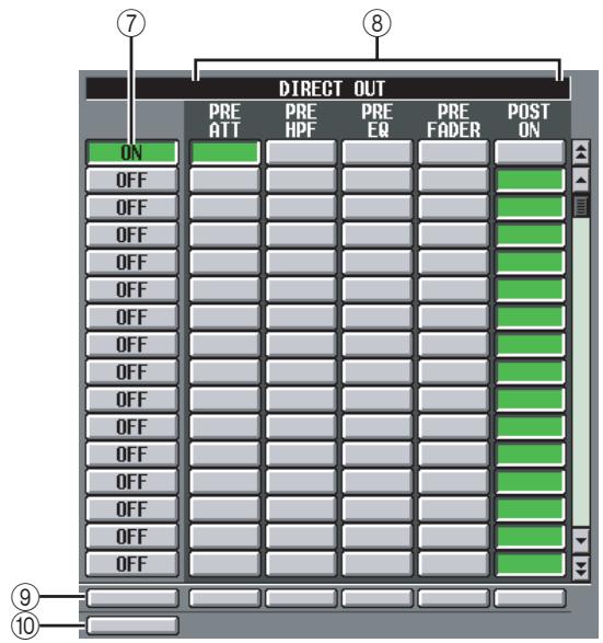
⑦ DIRECT OUT ON/OFF
These buttons switch direct output on/off for each channel.
(8) DIRECT OUT
Here you can select one of the following as the direct output location for each channel.
| PRE ATT | Immediately before the attenuator |
| PRE HPF | Immediately before the high-pass filter |
| PRE EQ | Immediately before the EQ (immediately after the PRE EQ of the INSERT I/O) |
| PRE FADER | Immediately before the fader |
| POST ON | Immediately after the CH [ON] key |
⑨ SET ALL
Turns on the corresponding item (direct out or the direct out point) for all channels (including channels not currently shown in the screen).
10 CLEAR ALL
Turns direct out off for all channels (including channels not currently shown in the screen).
NAME screen
Here you can assign a name to each input channel and DCA group.
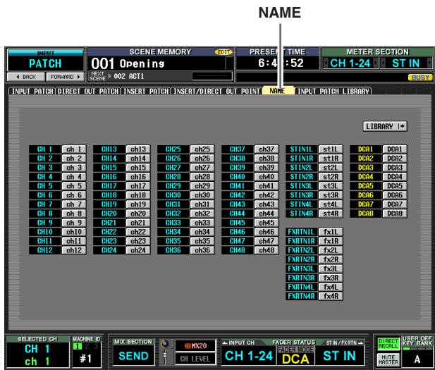
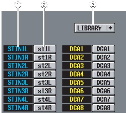
① Channel
This area indicates the input channel (input channel, ST IN channel) and DCA group numbers.
② Name
This area indicates the names currently assigned to each input channel and DCA group. If you click the name, a window will open allowing you to assign a name to the channel.
③ LIBRARY
This button accesses the INPUT PATCH LIBRARY screen ( p.283), where you can store/recall input channel patch (and name) library settings.
INPUT PATCH LIBRARY screen
Here you can recall, store, rename, or delete items in the input patch library.
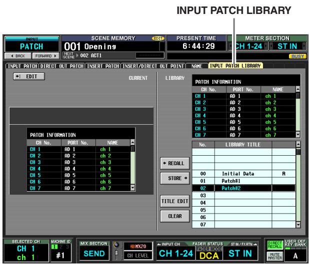
Except for the fact that these are patch settings for input channels, display and operations are the same as in the OUTPUT PATCH function OUTPUT PATCH LIBRARY screen. Refer to p.247.
INPUT HA/INSERT function
CH 1-24 (Input channel 1-24) screen
CH 25-48 (Input channel 25-48) screen
STIN/FXRTN (ST IN/FXRTN channel) screen
Here you can make settings for internal HAs (PM5D-RH model only) or external HAs assigned to input channels.
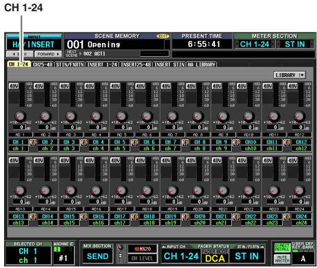
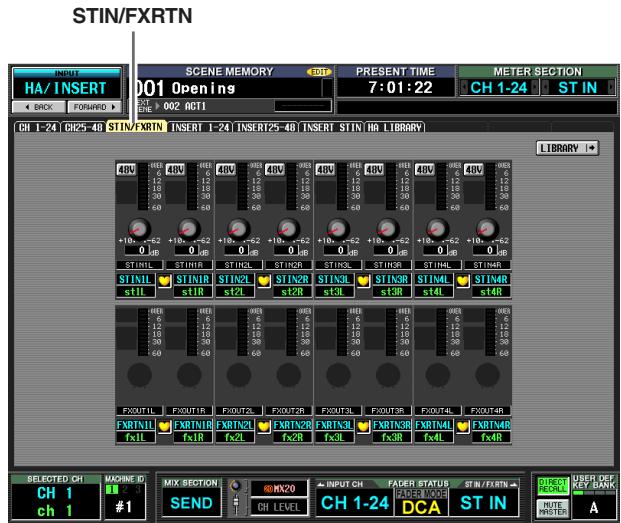
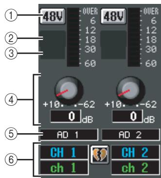
① +48V
② HPF (High Pass Filter)
③ Cutoff frequency
④ GAIN
⑤ Input port
These items are the same as in the OUTPUT INSERT function INSERT IN MIX1-24 screen and INSERT IN MATRIX/STEREO/MONITOR screen (p.248).
⑥ Channel
This area shows the number and name of the channel you are editing. Two paired channels are indicated by a heart symbol displayed between them.
Note
- Items ①-④ are not shown for channels to which nothing is patched, or for channels patched to an input port that does not have a HA. Items ② and ③ are not shown for channels patched to a port that has no high pass filter.
- To assign input ports to input channels, use the INPUT PATCH screen (INPUT PATCH function).
- HA settings are not linked even if two channels are paired. However, the GAIN knob setting is linked for HAs whose GANG button is turned on in the HA screen (SYS/W.CLOCK function).
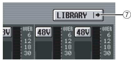
⑦ LIBRARY button
This button displays the HA LIBRARY screen ( p.230), where you can store/recall internal HA or external HA settings as library items.
Hint
The HA settings you edit in this screen are also reflected in the HA screen (SYS/W.CLOCK function).
INSERT 1-24 screen
INSERT 25-48 screen
INSERT STIN screen
Here you can make settings for internal HAs (PM5D-RH model only) or external HAs assigned to the insert-in of input channels.
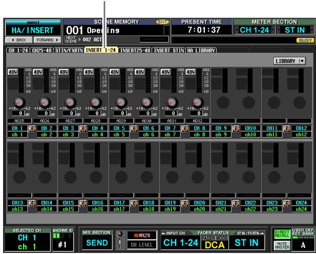
INSERT 1-24
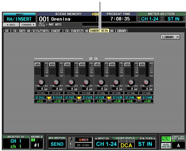
INSERT STIN
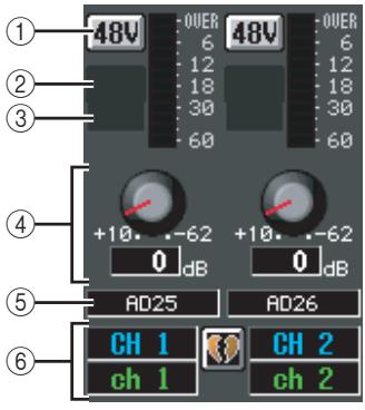
① + 48V
② HPF (High Pass Filter)
③ Cutoff frequency
④ GAIN
⑤ Input port
These items are the same as in the OUTPUT INSERT function INSERT IN MIX1-24 screen and INSERT IN MATRIX/STEREO/MONITOR screen (p.248).
⑥ Channel
This area shows the number and name of the channel you are editing. Two paired channels are indicated by a heart symbol displayed between them.
Note
- Items ①-④ are not shown for channels to whose insert-in nothing is patched, or for channels patched to an input port whose insert-in does not have a HA. Items ② and ③ are not shown for channels patched to a port that has no high pass filter.
- To assign an input port to an insert-in, use the INPUT PATCH screen (INPUT PATCH function).
- HA settings are not linked even if two channels are paired. However, the GAIN knob setting is linked for HAs whose GANG button is turned on in the HA screen (SYS/W.CLOCK function).
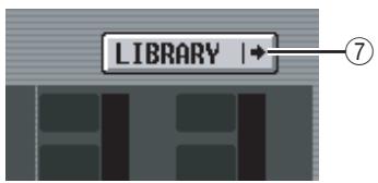
⑦ LIBRARY button
This button displays the HA LIBRARY screen ( p.230), where you can store/recall internal HA or external HA settings as library items.
Hint
The HA settings you edit in this screen are also reflected in the HA screen (SYS/W.CLOCK function).
HA LIBRARY screen
This screen is the same as HA LIBRARY in the SYS/ W.CLOCK function ( p.230).
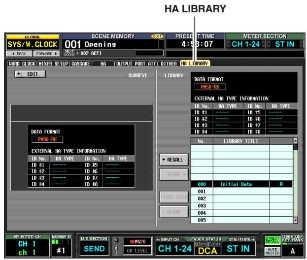
INPUT / EQ function
EQ PARAM (EQ parameter) screen
Here you can edit the EQ parameters of the selected input channel.
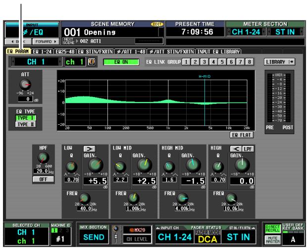
EQPARAM
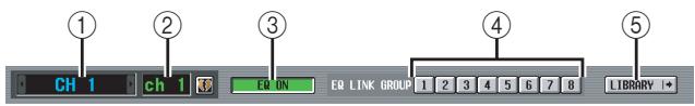
① Channel selection
Selects the input channel (input channel 1-48, STIN channel 1 - 4L / R ,FXRTN channel 1 - 4L / R
② Name
This is the name of the currently selected input channel. If the input channel is paired (or if a ST IN channel or FX RTN channel is selected), a heart symbol is displayed at the right. For an input channel, you can click this symbol to enable/disable pairing.
③ EQ ON/OFF
Turns the EQ on/off for that channel.
④ EQ LINK GROUP
Selects the EQ link group (1-8) to which the EQ of that channel belongs. EQ parameters are linked for input channels belonging to the same group.
Note
The input channel EQ link groups are independent from the output channel EQ link groups.
⑤ LIBRARY
This button accesses the INPUT EQ LIBRARY screen ( p.289), where you can store/recall input channel EQ library settings.
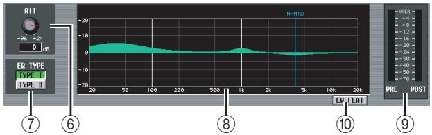
⑥ ATT (Attenuation)
This knob adjusts the amount of attenuation/gain immediately following AD conversion in a range of -96 dB to +24 dB. This is linked with the ATT knob in the /ATT 1-48 screen and /ATT STIN/FXRTN screen. The current value is displayed in the box located below the knob.
⑦ EQ TYPE
Selects the type of EQ. Turning the TYPE I button on selects the algorithm used in the 02R series. Turning the TYPE II button on selects a newly developed algorithm. TYPE II reduces the interference between bands.
⑧ EQ graph
This graph shows the approximate response of the EQ parameters. The colored vertical lines indicate the FREQ (center frequency) of the band for the parameter at which the cursor is located. (The color of each line matches the knob markings for each band.) The response curve will change when you edit the Q or GAIN of each band.
⑨ Level meters
These meters indicate the peak levels before EQ and after EQ. If the signal clips before or after EQ, the OVER segment will light.
⑩ EQFLAT
This button resets the GAIN parameters of all bands to the default value (± 0.0dB) .When you click this button, a confirmation message will appear.
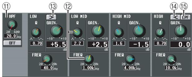
HPF (High Pass Filter)
The high pass filter located after attenuation and before EQ can be switched on/off, and you can adjust its cutoff frequency. The cutoff frequency can be adjusted in a range of 20 - 600Hz
(2) Knobs
These knobs adjust the Q, FREQ (center frequency), and GAIN (amount of boost/cut) for each band.
(LOW shelving)
If this button is on, the LOW EQ will function as a shelving-type EQ. The Q knob will disappear.
(14) (HIGH shelving)
If this button is on, the HIGH EQ will function as a shelving-type EQ. The Q knob will disappear.
LPF (Low Pass Filter)
If this button is on, the HIGH EQ will function as a low-pass filter. The Q knob will disappear, and the GAIN knob is used to switch the LPF on/off.
EQ 1-24 screen
EQ 25-48 switch
EQ STIN/FXRTN screen
These screens list the EQ settings for the input channels. Here you can also copy EQ settings between input channels.
Note
In some screens that include channel numbers as part of the screen name, changing the Pair Mode to Vertical Pairing in the MIXER SETUP screen will change the name of the screen.
Example: EQ 1-24 screen EQ 1,25-screen
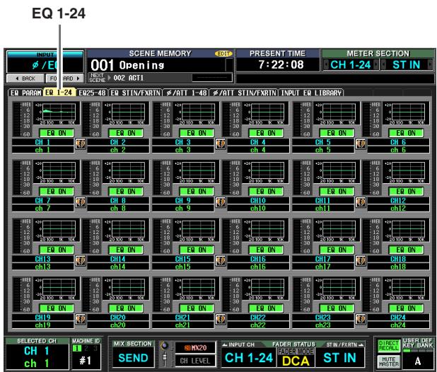
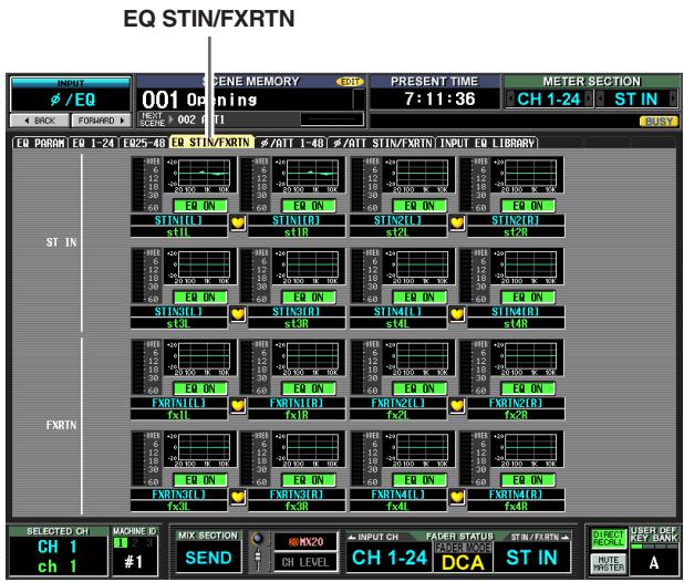
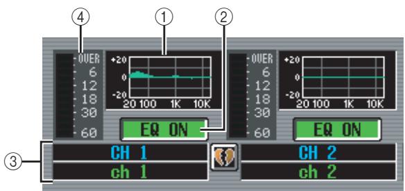
① EQ graph
This mini-graph shows the approximate EQ response for each input channel.
When you click the graph at which the cursor is currently located, the EQ PARAM screen for that channel will appear.
In this screen you can drag and drop the mini-graph from the desired channel to copy its EQ settings.
(When you drag and drop the mini-graph, a window will appear, asking you to confirm the copy operation.)
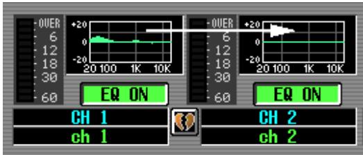
You can also copy EQ settings between the three screens EQ 1-24, EQ 25-48, and EQ STIN/FXRTN.
First drag the mini-graph over the EQ 1-24, EQ 25-48, or EQ STIN/FXRTN tabs in the screen (the screen will switch). Then drag and drop the mini-graph onto the desired channel, and a window will appear, asking you to confirm the copy operation.
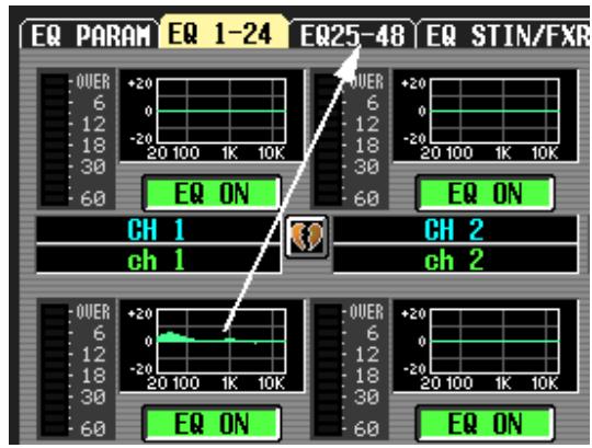
② EQ ON/OFF
Turns the EQ on/off for that channel. This is linked for two paired channels.
③ Channel
This is the number of the channel you are editing. Two paired channels are indicated by a heart symbol displayed between them.
④ Level meter
This meter indicates the peak level after EQ. If the signal clips, the OVER segment will light.
±b /ATT 1-48 (Phase/Attenuation 1-48) screen
/ATT STIN/FXRTN (Phase/Attenuation STIN/FXRTN) screen
Here you can adjust the amount of attenuation/gain immediately following AD conversion, and reverse the phase.
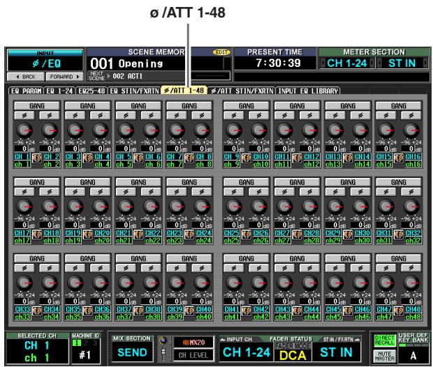
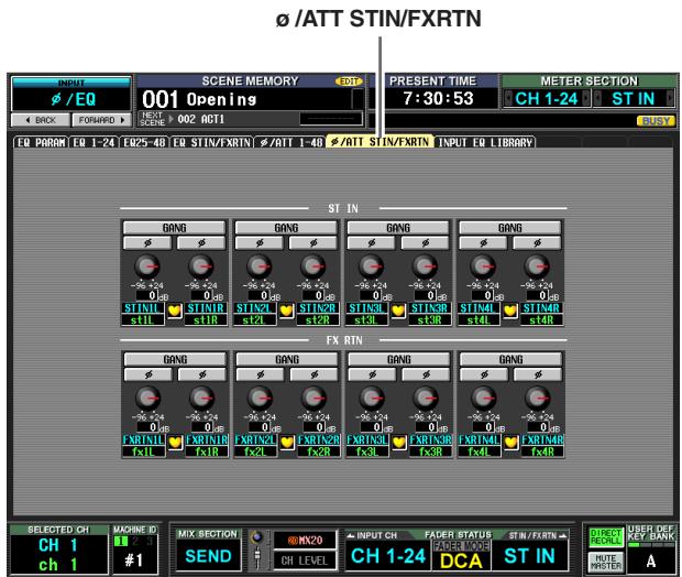
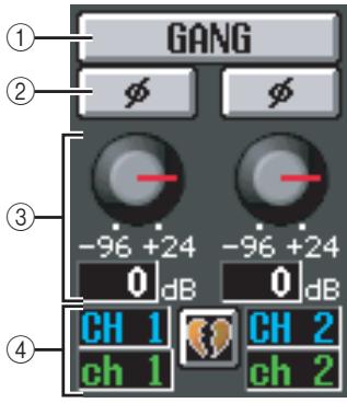
① GANG
When you turn this button on, attenuation/gain settings will be linked for adjacent odd-numbered/even-numbered channels (or the L/R sides of an STIN/ FXRTN channel).
If the settings are different when you turned the button on, they will maintain their relative difference while linked.
② (Phase)
This button inverts the phase of each channel's signal following AD conversion.
③ Attenuation/gain
For each channel, you can adjust the amount of attenuation/gain immediately following AD conversion over a range of -96 dB to +24 dB. This is linked with the ATT knob of the EQ PARAM screen. The current value is displayed in the box located below the knob.
④ Channel
This is the number and name of the channel. If two adjacent odd-numbered/even-numbered channels are paired (or if a STIN channel or FXRTN channel is displayed), a heart symbol is displayed between the two channels.
INPUT EQ LIBRARY screen
Here you can recall, store, rename, or delete items in the input EQ library.
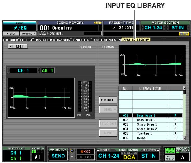
Except for the fact that these are EQ settings for the input channels, display and operations are the same as in the OUTPUT EQ function OUTPUT EQ LIBRARY screen. Refer to p.252.
INPUT GATE/COMP function
GATE PARAM (Gate parameter) screen
Here you can edit the gate parameters of the selected input channel.
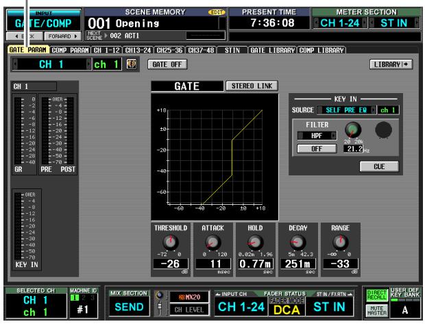
GATE PARAM
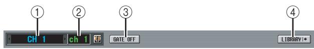
① Channel selection
Select the input channel (input channel, ST IN channel) that you want to edit.
② Name
This is the name of the currently selected input channel. If the input channel is paired (or if a ST IN channel is selected), a heart symbol is displayed at the right. For an input channel, you can click this symbol to enable/ disable pairing.
③ GATE ON/OFF
Turns the gate for that channel on/off.
④ LIBRARY
This button accesses the GATE LIBRARY screen ( p.294), where you can store/recall gate library settings for input channels.
(5) Level meters
These meters indicate the amount of gain reduction (GR), the peak level before (PRE) and after (POST) the gate, and the peak level of the key-in signal (KEY IN) that causes the gate to operate. If the signal clips, the OVER segment will light.
If stereo link is turned on for the input channel (or if a ST IN channel is selected), level meters for two channels are displayed.
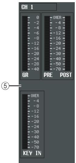
Hint
If GR METER ON/OFF LINK is turned on in the PREFER-ENCE 1 screen (UTILITY function), the gain reduction meter will not be displayed when the gate is off.
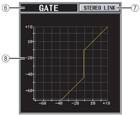
⑥ Type
Indicates the type of the currently selected gate.
Hint
To change the gate type, use the INPUT GATE LIBRARY screen to recall a library item that has a different type. You cannot change only the gate type in this screen.
⑦ STEREO LINK
This specifies whether parameter settings and gate operation by a key-in signal will be linked (STEREO LINK button on) for adjacent odd-numbered/even-numbered input channels and the L/R channels of ST IN channels, or not (STEREO LINK button off).
Key-in signal flow when Link=On
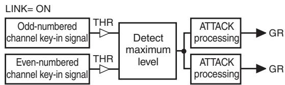
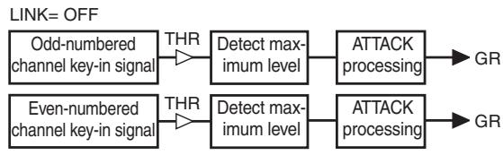
Key-in signal flow when Link= Off
Note
Stereo Link is fixed at On for paired channels.
Gate graph
This graph displays the approximate response of the gate.
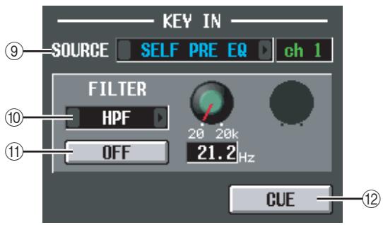
(9) KEY IN SOURCE
Here you can select one of the following as the key-in signal that will be used. (If an input channel is selected, its name will be displayed at the right.)
| SELF PRE EQ | The pre-EQ signal of the currently selected input channel |
| SELF POST EQ | The post-EQ signal of the currently selected input channel |
| CH 1-48 POST EQ | The post-EQ signal of the corresponding input channel (however, you can only choose channels belonging to the same group, within the seven groups CH1-8, CH9-16, CH17-24, CH25-32, CH33-40, CH41-48, and ST IN 1L/1R-4L/4R) |
| ST IN 1L/1R-4L/4R POST EQ | |
| MIX 21-24 | The output signal of the corresponding MIX channel immediately before the output patch |
10 FILTER
Select the type of filter to be applied to the selected key-in signal, from the following types.
HPF (High Pass Filter)
Passes the portion of the signal above the specified frequency (the cutoff frequency), and cuts the portion below. If you select this filter, use the knob at the right to adjust the cutoff frequency (20Hz - 20kHz)
- BPF (Band Pass Filter)
Passes only the specified frequency region (the band pass frequency), and cuts the rest of the signal. If you select this filter, use the knobs at the right to adjust the band pass frequency (20Hz - 20kHz) and Q (10.0-0.10).
LPF (Low Pass Filter)
Passes the portion of the signal below the specified frequency (the cutoff frequency), and cuts the portion above. If you select this filter, use the knob at the right to adjust the cutoff frequency (20Hz - 20kHz)
⑪ FILTER ON/OFF
This is an on/off switch for the filter applied to the key-in signal.
CUE
This button cue-monitors the currently selected key-in signal.
Note
Even if the cue mode is set to MIX CUE (which lets you monitor the mix of all channels whose [CUE] key is on), only the corresponding signal will take priority for monitoring when you turn on the CUE button in the GATE PARAM screen. (Any [CUE] keys that had been on at that time will be forcibly turned off.)
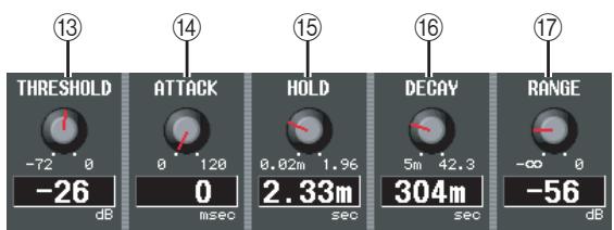
⑬ THRESHOLD (Threshold level)
Specifies the level at which the gate will open and close. The gate will open when the key-in signal exceeds this level, and will close when the signal falls below this level.
14 ATTACK (Attack time)
Specifies the time from when the key-in signal exceeds the threshold level until the gate opens.
15 HOLD (Hold time)
Specifies the time that the gate will remain open after the key-in signal falls below the threshold.
16 DECAY (Decay time)
- Specifies the time over which the gate will close after the hold time has elapsed.
17 RANGE
Specifies the amount of attenuation while the gate is closed.
COMP PARAM (Compressor parameter) screen
Here you can edit the compressor parameters of the selected input channel.
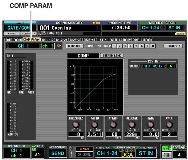
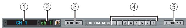
① Channel selection
Select the input channel (input channel, ST IN channel) that you want to edit.
② Name
This is the name of the currently selected input channel. If the input channel is paired (or if a ST IN channel is selected), a heart symbol is displayed at the right. For an input channel, you can click this symbol to enable/ disable pairing.
③ COMP ON/OFF (Compressor on/off)
Turns the compressor on/off for that channel.
(4) COMP LINK GROUP (Compressor link group)
Selects the compressor link group (1-8) to which that channel belongs. Compressor parameters are linked for input channels belonging to the same group.
Note
Input channel compressor link groups are independent from output channel compressor link groups.
⑤ LIBRARY
This button accesses the COMP LIBRARY screen ( p.256), where you can store/recall compressor library settings for input channels.
(6) Level meters
These meters indicate the amount of gain reduction (GR), the peak level before (PRE) and after (POST) the compressor, and the peak level of the key-in signal (KEY IN) that causes the compressor to operate. If the signal clips, the OVER segment will light.
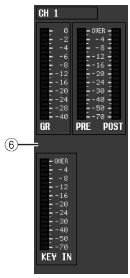
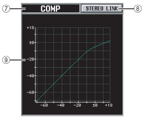
⑦ Type
Indicates the type of the currently selected compressor.
⑧ STEREO LINK
This specifies whether compressor parameter settings and key-in signal operation will be linked for adjacent odd-numbered/even-numbered input channels (STEREO LINK button on), or will be independent (STEREO LINK button off). (For details on compressor stereo link p.254)
⑨ Compressor graph
This graph displays the approximate response of the compressor.
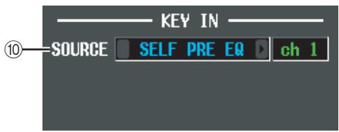
⑩ KEY IN SOURCE
Select the desired key-in signal from the following choices.
| SELF PRE EQ | The pre-EQ signal of the currently selected input channel |
| SELF POST EQ | The post-EQ signal of the currently selected input channel |
| CH 1-48 POST EQ | The post-EQ signal of the corresponding input channel (however, you can only choose channels belonging to the same group, within the seven groups CH1-8, CH9-16, CH17-24, CH25-32, CH33-40, CH41-48, and ST IN 1L/1R-4L/4R) |
| ST IN 1L/1R-4L/4R POST EQ | |
| MIX 21-24 | The output signal of the corresponding MIX channel immediately before the output patch |
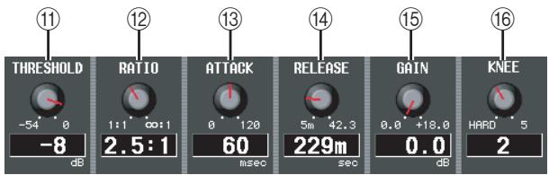
(1) THRESHOLD (Threshold level)
② RATIO
13 ATTACK (Attack time)
(14) RELEASE (Release time)
15 GAIN
16 KNEE
These parameters are the same as in the OUTPUT COMP function COMP PARAM screen (p.255).
CH 1-12 (Input channel 1-12) screen
CH 13-24 (Input channel 13-24) screen
CH 25-36 (Input channel 25-36) screen
CH 37-48 (Input channel 37-48) screen
ST IN (ST IN channel) screen
These screens list the gate/compressor settings for the input channels. Here you can also copy gate/compressor settings between input channels.
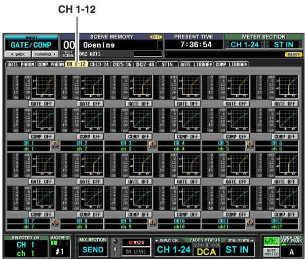
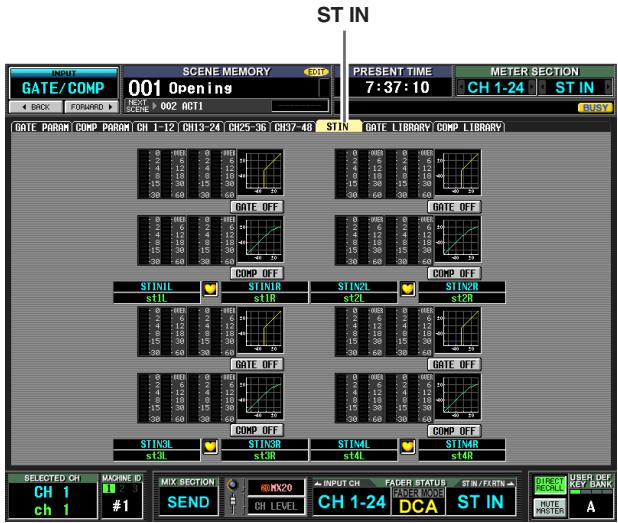
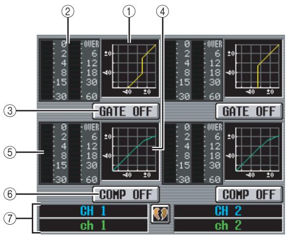
① Gate graph
This mini-graph shows the approximate gate response for each input channel. If you click the mini-graph, the GATE PARAM screen for that channel will appear.
(2) Level meters
These meters show the amount of gain reduction produced by the gate (at left), and the peak level of the signal after passing through the gate (at right). If the signal clips, the OVER segment will light.
③ GATE ON/OFF
Turns the gate for that channel on/off.
④ Compressor graph
This mini-graph shows the approximate compressor response for each input channel. If you click the mini-graph, the COMP PARAM screen for that channel will appear.
(5) Level meters
These meters show the amount of gain reduction produced by the compressor (at left), and the peak level of the signal after passing through the compressor (at right). If the signal clips, the OVER segment will light.
⑥ COMP ON/OFF (Compressor on/off)
Turns the compressor on/off for that channel.
⑦ Channel
This area shows the number and name of the channel you are editing. Two paired channels are indicated by a heart symbol displayed between them.
In this screen, you can copy gate/compressor settings by dragging and dropping the mini-graph of a desired channel onto another channel. You can also copy gate/compressor settings between different screens (for the procedure p.255).
GATE LIBRARY screen
Here you can recall, store, rename, or delete items in the gate library.
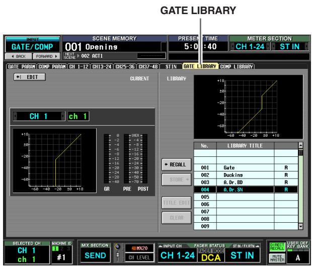
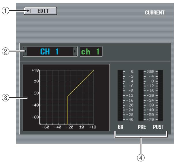
① EDIT
When you click this button, the GATE PARAM screen for the currently selected input channel will appear.
② Channel selection
Select the input channel that you want to edit. The name of the channel is displayed at the right.
③ Gate graph of the selected channel
This graph shows the approximate response of the gate for the currently selected channel.
(4) Level meters
These meters show the amount of gain reduction (GR), and the peak levels before the gate (PRE) and after the gate (POST). If the signal clips, the OVER segment will light.
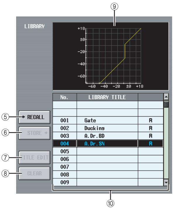
⑤ RECALL
Recalls the gate library item selected in the list into memory.
STORE
Stores the gate settings of the currently selected channel into the location selected in the list. When you click this button a window will appear, allowing you to name and save the settings.
(7) TITLE EDIT
Edits the title of the library item selected in the list. When you click this button a window will appear, allowing you to edit the title.
(8) CLEAR
Deletes the library item selected in the list. When you click this button, a confirmation message will appear.
Note
Library items with an "R" displayed in the right column of the list are read-only. Read-only items cannot be stored, renamed, or deleted.
Library gate graph
This graph indicates the approximate response of the gate library item selected in the list.
⑩ Library list
Use the scroll bar to select the library item on which you want to perform an operation. The selected library item will move to the center, and will be highlighted.
COMP LIBRARY (Compressor library) screen
Here you can recall, store, rename, or delete items in the compressor library.
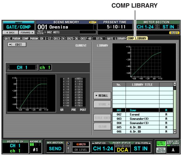
Except for the fact that these settings are for input channels, this is the same as the OUTPUT COMP function COMP LIBRARY screen. Refer to p.256.
INPUT DELAY function
CH 1-24 (Input channel 1-24) screen
CH 25-48 (Input channel 25-48) screen
ST IN (ST IN channel) screen
Here you can edit the delay parameters of the selected input channel.
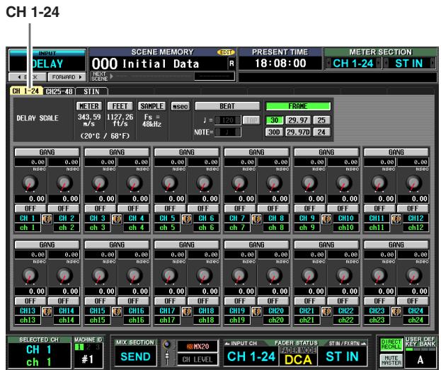
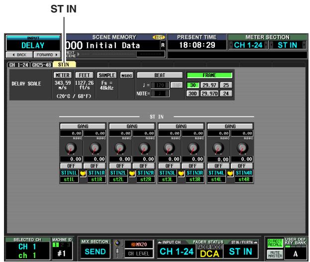
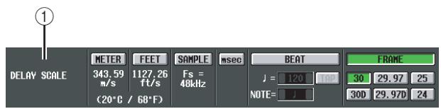
① DELAY SCALE
Here you can select the units in which the delay time is displayed. The units that can be selected are the same as in OUTPUT DELAY function DELAY SCALE
( p.257) . When you change the delay scale in the INPUT DELAY function, the delay scale of the OUTPUT DELAY function will also change accordingly.
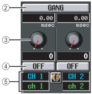
② GANG
③ Delay time knob
④ DELAY ON/OFF
These are the same as in the OUTPUT DELAY function (p.258).
⑤ Channel
This area shows the number and name of the input channel you are editing. Two paired channels (or a ST IN channel) are indicated by a heart symbol displayed between them. You can click this symbol to enable/dis-able pairing.
INPUT DCA/GROUP function
DCA GROUP ASSIGN screen
Here you can specify the input channels that will be assigned to DCA groups 1-8. The level of input channels belonging to the same DCA group can be adjusted as a whole using DCA faders 1-8.
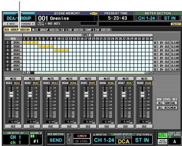
DCA GROUP ASSIGN
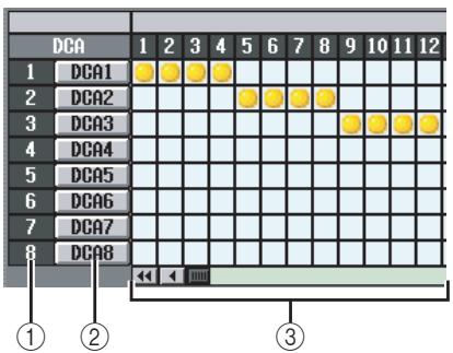
① DCA group
This is the number of the DCA group. The number corresponding to the grid where the cursor is located is highlighted.
② Name
This is the name of the DCA group. You can also click this area to edit the name.
③ Grid
This grid lets you assign input channels (horizontal rows) to DCA groups (vertical columns). Currently-patched grids are indicated by a symbol. Move the cursor to the desired grid and press the [ENTER] key (or click) to set/disable the assignment.
Hint
You can also assign a single input channel to multiple DCA groups for multiple DCA control.
Hint
DCA groups 1-6 are for input channels only, but DCA groups 7/8 can be used with both input channels and output channels. Both types of channel can exist in an identically-numbered group.
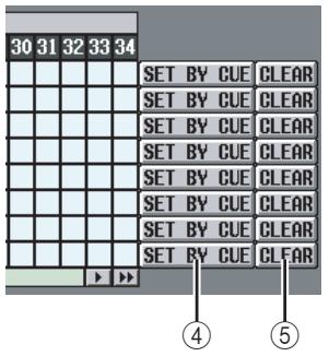
④ SET BY CUE (Assign by [CUE] key)
This specifies whether the [CUE] key will be used to make/cancel DCA group assignments. While the DCA group SET BY CUE button is on, pressing the [CUE] key of an input channel that can be assigned to the corresponding group will assign the channel to the group. (Press the [CUE] key once again to cancel the assignment.)
Hint
The SET BY CUE button can be turned on for only one DCA group. This is automatically turned off when you change screens or turn off the power.
⑤ CLEAR
This button clears all input channels assigned to that DCA group.
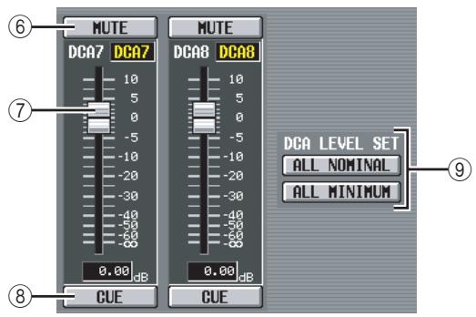
(6) MUTE
These buttons switch muting on/off for DCA groups 1-8. They are linked with DCA [MUTE] keys 1-8 in the DCA strip of the panel.
DCA faders
These faders adjust the levels of DCA groups 1-8. They are linked with DCA faders 1-8 in the DCA strip.
CUE
These buttons cue-monitor DCA groups 1-8. They are linked with DCA [CUE] keys 1-8 in the DCA strip of the panel.
DCA LEVEL SET
Use the following two buttons to operate DCA groups 1-8 together.
- ALL NOMINAL
Clicking this button will move DCA faders 1-8 to nominal level (0 dB).
- ALL MINIMUM
Clicking this button will move DCA faders 1-8 to the - dB position.
MUTE GROUP ASSIGN screen
Here you can specify the input channels that will be assigned to mute groups 1-8. Muting can be switched on/off together for channels assigned to the same mute group.
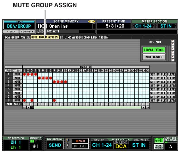
Except for the fact that these settings apply to input channels, the display and operations are the same as in the OUTPUT DCA/GROUP function MUTE GROUP ASSIGN screen. Refer to p.259.
Hint
Mute groups 1-8 can be used with both input channels and output channels. Both types of channel can exist in the identically-numbered mute group.
EQ LINK ASSIGN screen
Here you can specify the input channels that will be assigned to EQ link groups 1-8. EQ parameters are linked for channels belonging to the same group.
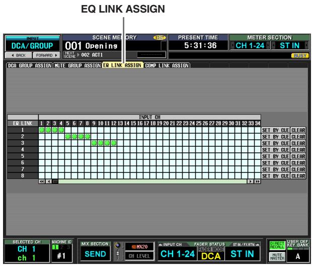
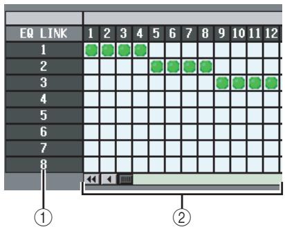
① EQ link group
These are the EQ link group numbers. The number corresponding to the grid where the cursor is located is highlighted.
② Grid
This grid lets you assign input channels (horizontal rows) to EQ link groups (vertical columns). Currently-patched grids are indicated by a symbol. Move the cursor to the desired grid and press the [ENTER] key (or click) to set/disable the assignment.
Hint
Input channels and output channels use separate EQ link groups. Input channels use groups A-H , and output channels use groups 1-8.
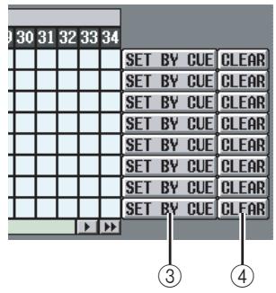
③ SET BY CUE (Assign by [CUE] key)
This specifies whether the [CUE] key will be used to make/cancel EQ link group assignments. While the EQ link group SET BY CUE button is on, pressing the [CUE] key of a channel that can be assigned to the corresponding group will assign the channel to the group. (Press the [CUE] key once again to cancel the assignment.)
Hint
The SET BY CUE button can be turned on for only one EQ link group. This is automatically turned off when you change screens or turn off the power.
(4) CLEAR
This button clears all input channels assigned to that EQ link group.
COMP LINK ASSIGN (Compressor link assign) screen
Here you can specify the input channels that will be assigned to compressor link groups 1-8. Compressor parameters are linked for channels belonging to the same group.
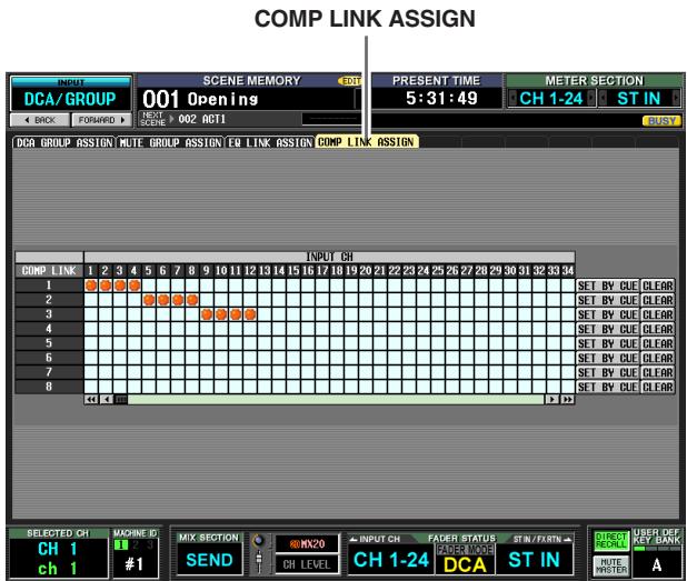
Except for the fact that these settings apply to input channels, the display and operations are the same as in the OUTPUT DCA/GROUP function COMP LINK ASSIGN screen. Refer to p.261.
Hint
Input channels and output channels use separate compressor link groups. Input channels use groups A-H, and output channels use groups 1-8.
PAN/ROUTING function
CH to MIX (Channel to mix) screen
Here you can send signals from input channels to the desired MIX bus. In this screen you can also switch the type (VARI or FIXED) of each MIX bus, and specify the location from which the signal will be sent.
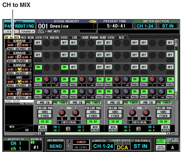
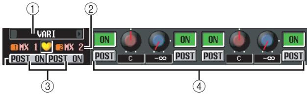
① Type selection
Here you can select the mix bus type for every two adjacent odd-numbered/even-numbered MIX buses. You can choose one of the following types.
FIXED
The send level of the MIX bus is fixed at nominal level (0.0 dB). Choose this if you want to use the MIX bus as a group output or as a bus output for recording on a multitrack recorder.
VARI (Variable)
The send level of the MIX bus is adjustable. Choose this if you want to use the MIX bus as an external effect send or as a foldback output.
Hint
If surround mode is enabled, the type indication will change to "SURROUND" for MIX buses used as surround buses. You cannot change the mix bus type during this time.
② MIX bus
This is the number and name of the MIX bus to which the signal is sent. Paired MIX buses are indicated by a heart symbol displayed between them. You can click this symbol to enable/disable pairing.
③ POST ON/POST TO ST (Post on / Post to stereo)
This button lets you specify in greater detail the location from which post-fader signals will be sent from input channels to this MIX bus. You can choose one of the following two send locations.
POSTON
The signal will be sent from immediately after the [ON] key.
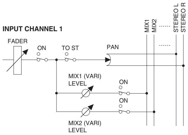
POST ON/POST TO ST= POST ON
POST TO ST
The signal will be sent from immediately after the [TO STEREO] key.
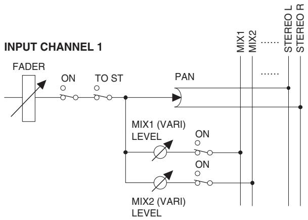
POST ON/POST TO ST= POST TOST
Hint
This setting applies to the signals sent from all input channels to the corresponding MIX bus.
CH to MIX (Channel to mix)
In this area, the signals sent from input channels / ST IN channels (vertical columns) to MIX buses (horizontal rows) can be switched on/off and their level adjusted.
The buttons and knobs displayed here will differ depending on the type (FIXED or VARI) of the send-destination MIX bus, and on whether the MIX buses are paired.
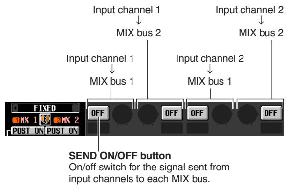
□ Type = FIXED, Pairing disabled

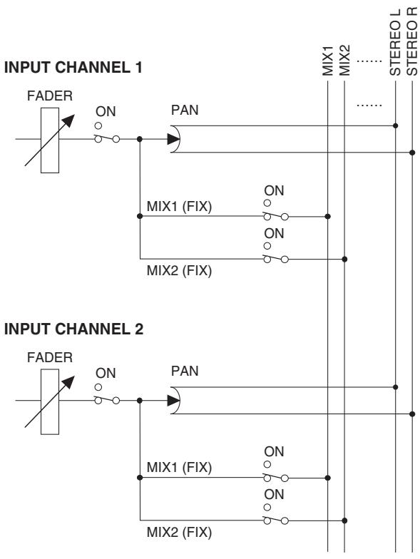
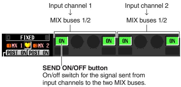
□ Type = FIXED, Pairing enabled

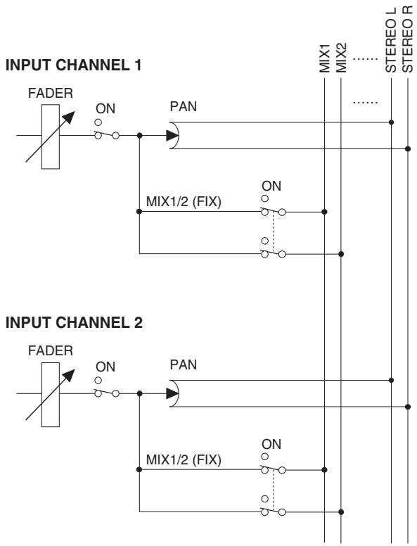
□ Type = VARI, Pairing = disabled
SEND ON/OFF button
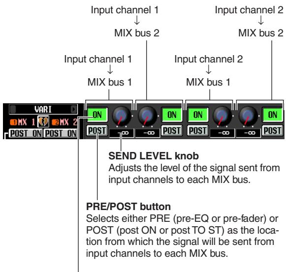
On/off switch for the signal sent from input channels to each MIX bus.

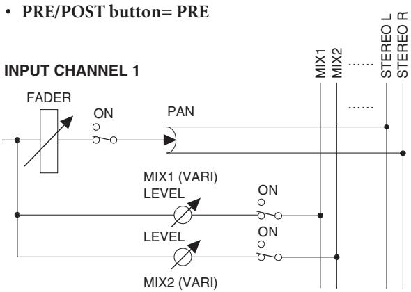
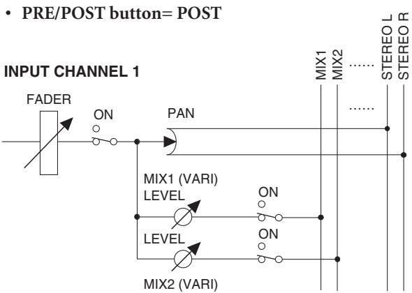
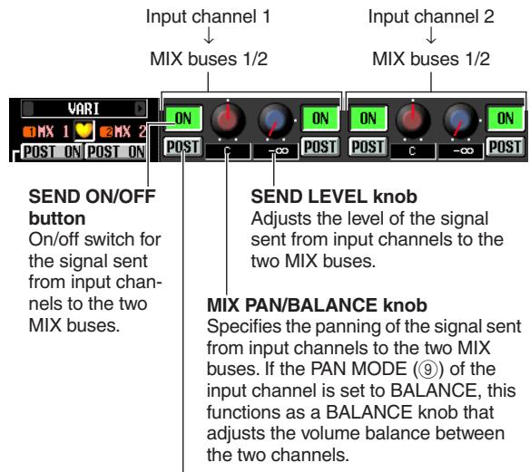
Type = VARI, Pairing enabled
PRE/POST button
Selects either PRE (pre-EQ or pre-fader) or POST (post ON or post TO ST) as the location from which the signal will be sent from input channels to each MIX bus.
| MIX CH | MIX MINUS | CH 1 ch 1 | CH 2 ch 2 | MIX MINUS |
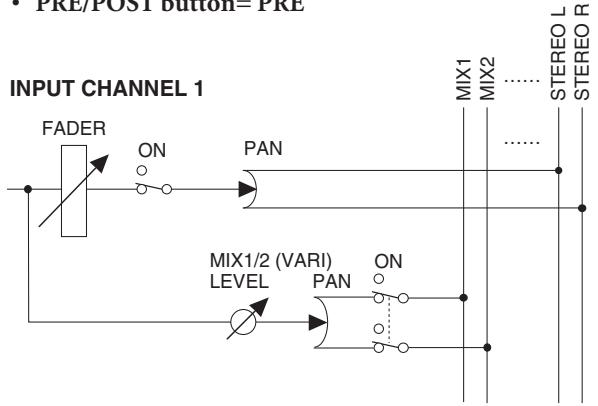
- PRE/POST button=PRE
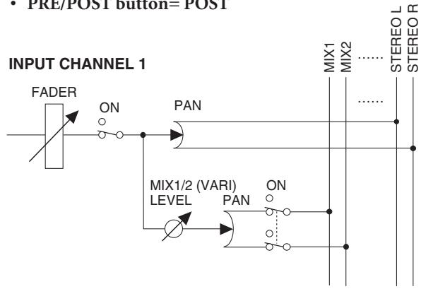
- PRE/POST button=POST
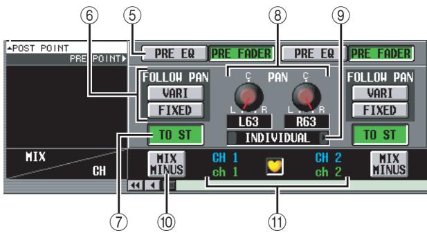
⑤ PRE EQ/PRE FADER
These buttons let you specify in greater detail the location from which the pre-fader signal will be sent from an input channel to the MIX buses. You can choose one of the following two send locations.
| PRE FADER | Immediately before the fader |
| PRE EQ | Immediately before the EQ |
Hint
This setting applies to the signal sent from the corresponding input channel to all MIX buses.
(6) FOLLOW PAN
These buttons specify how the TO ST PAN knob (⑧) will affect the signal sent from the input channel to MIX buses.
VARI
If this button is on, the PAN knob displayed in the CH to MIX area (④) will be linked with the TO ST PAN knob (⑧) if VARI-type MIX buses are paired.
FIXED
If this button is on, the signal from after the TO ST PAN (⑧) knob will be sent to FIXED-type MIX buses.
⑦ TO ST (To stereo)
This button specifies whether the input channel / ST IN channel will send its signal to the STEREO bus. This is linked with the [TO STEREO] switch in the SELECTED CHANNEL section.
⑧ TO ST PAN (To stereo pan)
Here you can adjust the panning of the signal sent from the input channel / ST IN channel to the STEREO bus. (The current value is shown in the boxes immediately below.) This is linked with the encoder if PAN is selected as the encoder mode, and with the [PAN] encoder of the SELECTED CHANNEL section.
PAN MODE
Here you can select one of the following ways in which pan settings will be linked between adjacent odd-numbered/even-numbered input channels (or the left/right channels of a ST IN channel).
- INDIVIDUAL
The two pan settings will be independent.
GANG PAN
The two pan settings will be linked in the same direction. If the two pan values are different when you turn on this button, pan will be linked while preserving the existing difference in values.
- INV. GANG (Inverted gang)
The two pan settings will operate in opposite directions.
BALANCE
The two PAN knobs will function as BALANCE knobs that adjust the balance of the signal sent from the odd-numbered/even-numbered channels (or the L/R channels of the ST IN channel) to the STEREO bus L/R. If you choose this setting, the two knobs will be reset to the center position, and will be linked in the same direction. Also, the knob markings will change from red to white.
Note
- Pan mode is always valid, even if the send-source input channels are not paired.
- You will be unable to operate the TO ST PAN knobs if you select GANG PAN mode when the two pan knobs are set to far left and right, or if you select INV.GANG when both pan knobs are turned all the way in the same direction.
10 MIX MINUS
This function sends the same mix as the STEREO bus — but with a specific input channel removed — to the desired MIX bus. If you need to send a monitor mix to a performer or announcer, this is a quick way to give them the same mix as the STEREO bus but without their own voice.
Access the desired source input channel in the screen, and click the MIX MINUS button for that channel; a window will appear, allowing you to select the MIX bus for which to make Mix Minus settings.
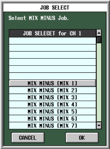
Hint
As a shortcut to access the above window, you can simultaneously press the [SEL] key of the INPUT/ST IN channel strip and the [SEL] key of the MIX section. However, be aware that holding down either one of these keys by itself will access a different shortcut.
In the above window, select the send-destination MIX bus and click the OK button; the following parameters will change in the CH to MIX screen.
- In the CH to MIX area of the send-destination MIX bus, all ON/OFF buttons will turn on.
- In the CH to MIX area of the send-destination MIX bus, all PRE/POST buttons will be set to POST.
- The send level of signals sent from the source input channel to the destination MIX bus will be lowered to - dB.
-
The send level of signals sent from all input channels other than the above to the destination MIX bus will be set to nominal level (0.0 dB).
-
The POST ON/POST TO ST button will be set to POST TO ST for the destination MIX bus.
Note
- Mix Minus does not switch a "mode"; rather, it is a quick way to make certain settings. This means that even after executing Mix Minus, you can freely edit the parameters of the CH to MIX screen.
- When you execute the Mix Minus operation, only the input channel you selected as the source will be removed from the mix. If you want to remove more than one input channel from the signal sent to a specific MIX bus, execute the Mix Minus operation and then manually change the settings of other channels.
- If the input channel is paired (or if a ST IN channel is selected), the send level of the signal sent from both channels to the target MIX bus will be set to - .
- The Mix Minus operation is valid even if the destination MIX bus is paired. In this case, the PAN setting of the input channel will be reflected by the PAN settings of the paired MIX buses.
⑪ Input channel
This is the source input channel (or channels). Paired input channels (or a ST IN channel) are indicated by a heart symbol displayed between them. For an input channel, you can click this symbol to enable/disable pairing.
You can move the cursor to a parameter in the CH to COPY area, and then hold down the [SHIFT] key and click (or press the [SHIFT] key + [ENTER] key) to copy the value of that parameter to another channel (in the horizontal direction) or to another MIX bus (in the vertical direction), or to switch all parameters on/off. You can use this method to set the following parameters.
- Mix send on/off
Move the cursor to the SEND ON/OFF button of the CH to COPY area; then hold down the [SHIFT] key and click (or press the [SHIFT] key + [ENTER] key) to access the following window.
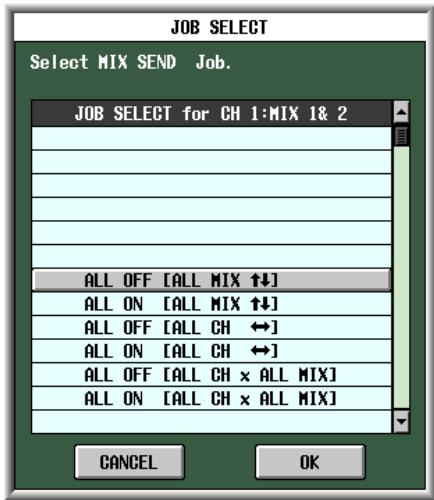
To set multiple parameters at once, use the [DATA] encoder to select one of the following items, and click the OK button.
ALL OFF [ALL MIX ↑↓]
ALL ON [ALL MIX↑↓]
Switch the signals sent from the selected input channel to all MIX buses on or off together.
ALL OFF [ALL CH ]
ALL ON [ALL CH ]
Switch the signals sent from all input channels to the selected MIX bus on or off together.
ALL OFF [ALL CH x ALL MIX]
ALL ON [ALL CH x ALL MIX]
Switch the signals sent from all input channels to all MIX buses on or off together.
- Mix send position
Move the cursor to a PRE/POST button in the CH to COPY area; then hold down the [SHIFT] key and click (or press the [SHIFT] key + [ENTER] key) to access the following window.
![YAMAHA PM5D-RH - ALL ON [ALL MIX↑↓] - 1](/content/2025/01/115055/images/2a6740b16f07fd3ff324ad0ad9cc3da10b43c1d68f62505083bdd20ac94bdbb7.jpg)
To set multiple parameters at once, use the [DATA] encoder to select one of the following items, and click the OK button.
ALL POST [ALL MIX↑↓]
ALL PRE [ALL MIX ↑↓]
Switch the send position of the signal sent from the selected input channel to all MIX buses to either post-fader or pre-fader.
ALL POST [ALL CH ]
ALL PRE [ALL CH ]
Switch the send position of the signal sent from all input channels to the selected MIX bus to either post-fader or pre-fader.
ALL POST [ALL CH x ALL MIX]
ALL PRE [ALL CH x ALL MIX]
Switch the send position of the signal sent from all input channels to all MIX buses to either post-fader or pre-fader.
Note
These "all-at-once" operations are ignored by FIXED-type MIX buses.
- Mix send level
Move the cursor to a SEND LEVEL knob in the CH to COPY area; then hold down the [SHIFT] key and click (or press the [SHIFT] key + [ENTER] key) to access the following window.
![YAMAHA PM5D-RH - ALL ON [ALL MIX↑↓] - 2](/content/2025/01/115055/images/b1ddc19273edacaa0035b0e0151e433c8232613652874c850fb06d235531c75a.jpg)
To set multiple parameters at once, use the [DATA] encoder to select one of the following items, and click the OK button.
LEVEL COPY [ALL MIX 14]
The value of the selected SEND LEVEL knob will be copied to the send level of the signals sent from that input channel to all MIX buses.
LEVEL COPY [ALL MIX ]
The value of the selected SEND LEVEL knob will be copied to the send level of the signals sent from all input channels to that MIX bus.
LEVEL COPY [ALL CH x ALL MIX]
The value of the selected SEND LEVEL knob will be copied to the send level of the signals sent from all input channels to all MIX buses.
Note
These "all-at-once" operations are ignored by FIXED-type MIX buses.
- Mix pan/balance
When the destination MIX bus is paired, move the cursor to a MIX PAN/BALANCE knob displayed in the CH to COPY area; then hold down the [SHIFT] key and click (or press the [SHIFT] key + [ENTER] key) to access the following window.
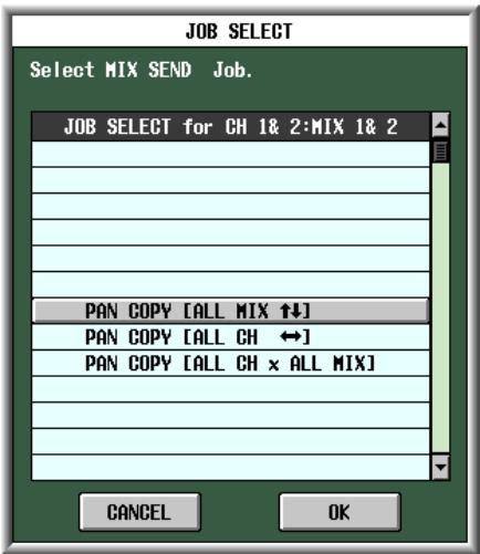
To set multiple parameters at once, use the [DATA] encoder to select one of the following items, and click the OK button.
PAN (BAL) COPY [ALL MIX 14]
The value of the selected MIX PAN/BALANCE knob will be copied to the pan (balance) of signals sent from that channel to all paired MIX buses.
PAN (BAL) COPY [ALL MIX ]
The value of the selected MIX PAN/BALANCE knob will be copied to the pan (balance) of signals sent from all channels to that MIX bus.
PAN (BAL) COPY [ALL CH x ALL MIX]
The value of the selected parameter will be copied to the pan (balance) of signals sent from all channels to all paired MIX buses.
Note
- This operation is ignored by unpaired MIX buses and FIXED-type MIX buses.
- You cannot copy PAN parameters to BALANCE parameters (or vice versa).
- Copying is invalid for channels whose VARI button (in the FOLLOW PAN area) is on.
MIX SEND VIEW screen
This screen lists the signals sent from the input channels to the MIX buses. You can also edit the settings from within this screen.
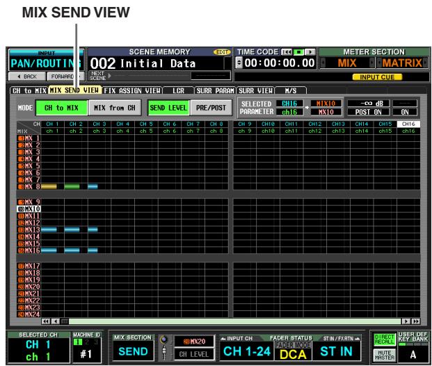

① CH to MIX/MIX from CH
Select one of the following two types of screen display.
□ When the CH to MIX button is on
The screen shows the status of the signals sent from a specific input channel (input channel / ST IN channel) to all MIX buses. (Use the scroll bar to see input channels that are not currently shown.)
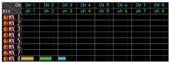
□ When the MIX from CH button is on
The screen shows the status of the signals sent from all input channels to a specific MIX bus.
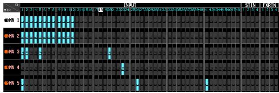
② SEND LEVEL, PRE/POST (Send level / Send point)
Select one of the following two parameters to view in the grid.
□ When the SEND LEVEL button is on
The send levels of the signals sent from input channels to MIX buses are shown in the grid as bar graphs. Except for the fact that the send-sources are input channels and the send-destinations are MIX buses, the bar graph display is the same as in the MIX to MATRIX VIEW screen (MATRIX/ST function) ( p.264).
Depending on the send location of the signal being sent to the MIX bus, the color of the bar graph will differ as follows.

(green) . PRE EQ (immediately before the EQ)

(yellow) ... PRE FADER (immediately before the fader)

(blue) .POST ON (immediately after the [ON] key) or POST TO ST (immediately after the [TO ST] key)
To edit the send level of a signal, move the cursor to the grid where the desired channel and MIX bus intersect, and turn the [DATA] encoder. To switch a MIX send on/off, click the grid where the desired channel and MIX bus intersect.
If the SEND LEVEL button is on, you can select a desired grid and copy its send level (pan) value to other channels (horizontal direction) or to other MIX buses (vertical direction), or switch all grids on/off simultaneously.
To do so, move the cursor to the desired grid; then hold down the [SHIFT] key and press the [ENTER] key. (Alternatively, hold down the [SHIFT] key and click the desired grid.) When the following window appears, select one of the following choices to copy, and click the OK button.
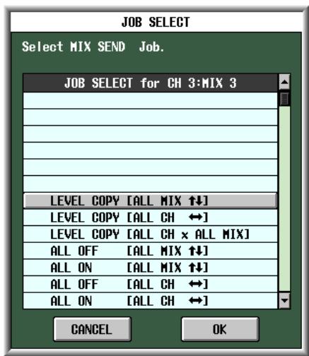
LEVEL COPY [ALL MIX↑]
Copy the send level (pan) value of the selected grid to all MIX buses.
LEVEL COPY [ALL CH ]
Copy the send level (pan) value of the selected grid to all input channels.
LEVEL COPY [ALL CH x ALL MIX]
Copy the send level (pan) value of the selected grid to all input channels / all MIX buses.
ALL OFF [ALL MIX↑↓]
Turn off the signals sent from the specified input channel to all MIX buses.
ALL ON [ALL MIX↑]
Turn on the signals sent from the specified input channel to all MIX buses.
ALL OFF [ALL CH ]
Turn off the signals sent from all input channels to the specified MIX bus.
ALL ON [ALL CH ]
Turn on the signals sent from all input channels to the specified MIX bus.
ALL OFF [ALL CH x ALL MIX]
Turn off the signals sent from all input channels to all MIX buses.
ALL ON [ALL CH x ALL MIX]
Turn on the signals sent from all input channels to all MIX buses.
□ When the PRE/POST button is on
This screen shows the send positions of the signals sent from the input channels to the MIX buses.

Each indication has the following significance.

(green) . . . PRE EQ (immediately before the EQ)

(yellow) .. PRE FADER (immediately before the fader)

(gray) .POST ON (immediately after the [ON] key)

(red) ...... POST TO ST (immediately after the [TO ST] key)
To change the send position of a signal, move the cursor to the grid where the desired channel and MIX bus intersect, and press the [ENTER] key, or click, or turn the [DATA] encoder.
If the PRE/POST button is on, the send position for all grid locations can be changed simultaneously. To do so, hold down the [SHIFT] key and click the desired grid. (Alternatively, move the cursor to the desired grid; then hold down the [SHIFT] key and press the [ENTER] key.) When the following window appears, select one of the following choices and click the OK button.
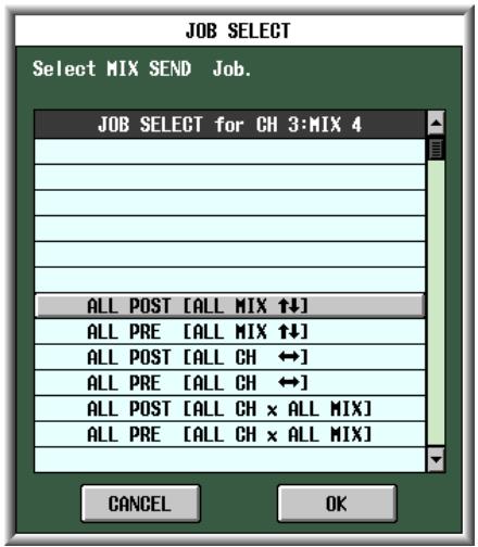
ALL PRE [ALL MIX ↑↓]
Specify pre-fader as the send position for signals sent from the specified input channel to all MIX buses.
ALL POST [ALL MIX↑↓]
Specify post-fader as the send position for signals sent from the specified input channel to all MIX buses.
ALL PRE [ALL CH ]
Specify pre-fader as the send position for signals sent from all input channels to the specified MIX bus.
ALL POST [ALL CH ]
Specify post-fader as the send position for signals sent from all input channels to the specified MIX bus.
ALL PRE [ALL CH x ALL MIX]
Specify pre-fader as the send position for signals sent from all input channels to all MIX buses.
ALL POST [ALL CH x ALL MIX]
Specify post-fader as the send position for signals sent from all input channels to all MIX buses.
③ Grid
This area shows various settings for the signals sent from the input channels (horizontal rows) to the MIX buses (vertical columns). The red lines extending toward the left and upward indicate the corresponding input channel and MIX bus for the grid at which the cursor is now located.
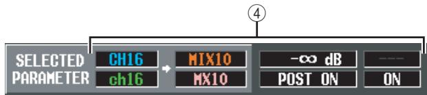
(4) SELECTED PARAMETER (currently selected parameter)
This indicates the input channel and MIX bus for the grid where the cursor is currently located. The four boxes at right indicate the values for the grid where the cursor is currently located.
FIX ASSIGN VIEW screen
This screen lists the signals sent from the input channels to the buses and direct outputs. You can also set or cancel these assignments from within this screen.
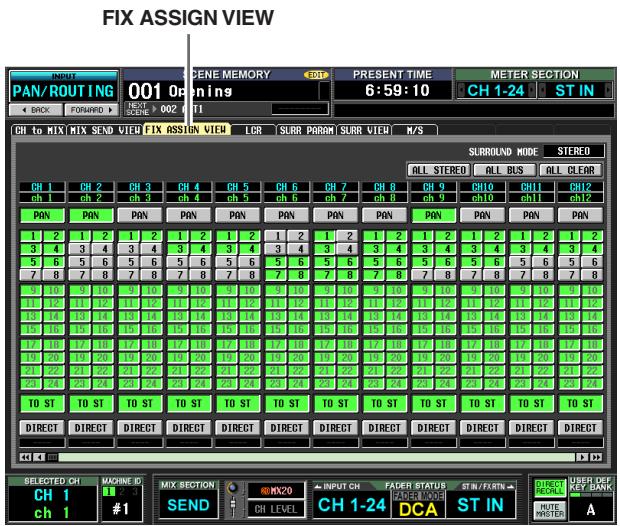
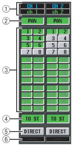
① Input channel
This area indicates the number and name of the input channel you are editing.
② PAN
If this button is on, the input channel's TO STEREO PAN knob setting will also apply to the signal sent to FIXED-type MIX buses. This is linked with the FOLLOW PAN FIXED button of the CH to MIX screen (PAN/ROUTING function).
③ Bus assignments
These buttons assign the corresponding input channel to FIXED-type MIX buses. These are linked with the SEND ON/OFF buttons of the CH to MIX screen (PAN/ROUTING function). For VARI-type MIX buses, the buttons are grayed-out and inoperable.
Note
If a surround mode other than STEREO is selected, the buttons for MIX buses used as surround buses will be named by their surround channel (e.g., L, C, R) rather than by number.
④ TO ST (To stereo)
If this button is on, the corresponding input channel is assigned to the STEREO bus. This is linked with the TO ST button of the CH to MIX screen (PAN/ROUTING function).
⑤ DIRECT
If this button is on, the signal of the corresponding input channel will be sent to the output port selected as the direct output. This is linked with the DIRECT OUT ON/OFF button in the INSERT/DIRECT OUT POINT screen (IN PATCH function).
⑥ Output port
This area indicates the output port that is patched in the DIRECT OUT PATCH screen (INPUT PATCH function) to the direct output of this input channel
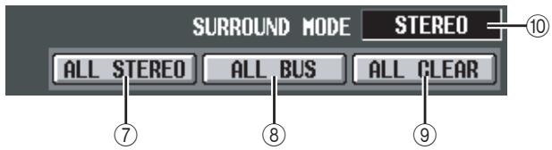
⑦ ALL STEREO
Clicking this button enables the assignment of all input channels to the STEREO bus.
(8) ALL BUS
Clicking this button enables the assignment of all input channels to FIXED-type MIX buses.
(9) ALL CLEAR
Clicking this button cancels all assignments in the FIX ASSIGN VIEW screen.
⑩ SURROUND MODE
This indicates the currently selected surround mode.
LCR screen
Here you can make settings for LCR mode, which allows three-channel playback by adding a CENTER channel to the L/R channels of the STEREO bus.
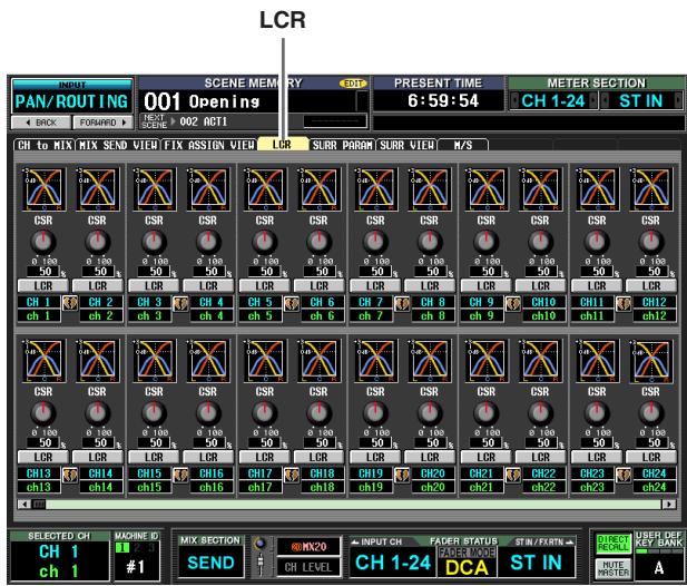
Except for the fact that the send-sources are input channels, the display and operations are the same as in the MATRIX/ST function LCR screen. Refer to p.267.
SURR PARAM (Surround parameter) screen
Here you can perform realtime control of surround panning for the two currently selected input channels.
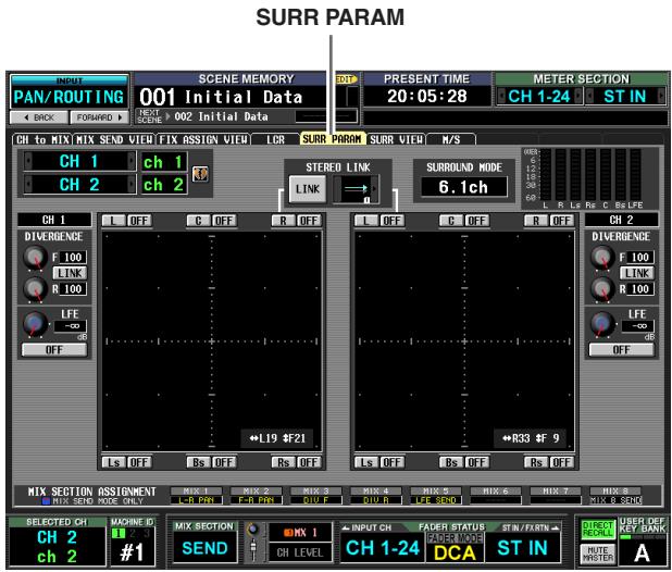
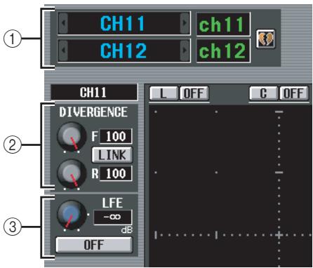
① Channel selection
Select the two adjacent odd-numbered/even-numbered input channels (or ST IN channel L/R) that you want to control. The names of these channels are displayed at the right.
(2) DIVERGENCE
These controls specify the proportion at which the signals are sent to each surround bus when the input channel is positioned in the center. Depending on the currently selected surround mode, the displayed parameters will differ as follows.
□ If Surround Mode = 3 - 1ch / 5.1ch
A knob for controlling the front divergence is displayed. Use this knob to specify the proportion (0- 100) at which a signal positioned in the center will be sent to the center bus (C) and the left/right buses (L, R). With a setting of 0 the signal will be sent only to the left/right buses, and with a setting
of 100 it will be sent only to the center bus. With a setting of 50, the signal will be sent at the same level to the left/right and center buses.
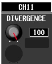
□ If Surround Mode = 6.1ch
An F knob for controlling the front divergence and an R knob for controlling the rear divergence are displayed. Use these two knobs to specify the proportion (0-100) at which a signal positioned in the center will be sent to the center buses (C, S, Bs) and the left/right buses (L, R, Ls, Rs).
In 6.1ch mode, a LINK button that links the front and rear divergence is displayed between the F knob and R knob. When you turn the LINK button on, the F knob value will be copied to the R knob, and the F knob and R knob values will be linked.
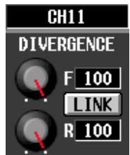
③ LFE (Low Frequency Effect)
This adjusts the output level of the signal sent from the input channel to the LFE (Low Frequency Effect) bus for a subwoofer. You can use the ON/OFF button to switch the signal sent from the input channel to the LFE bus on/off.
The LFE knob and ON/OFF button are displayed only when the surround mode is 5.1ch or 6.1ch.
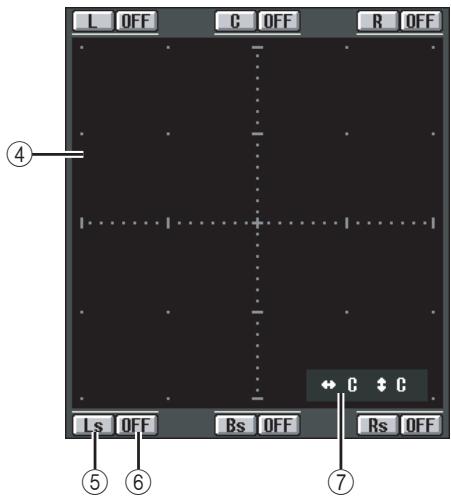
④ Surround pan grid
This grid lets you control the surround panning, with the listening point at the center. The current setting is indicated by a O symbol.
⑤ Position buttons
These buttons correspond to each surround bus. When you click a button, the surround panning will move to that position.
⑥ SURROUND BUS ON/OFF buttons
These buttons are on/off switches for the signal sent from the input channel to the corresponding surround bus.
⑦ Surround pan position
This indicates the coordinate locations of the O symbol in the left/right direction and the front/rear direction.
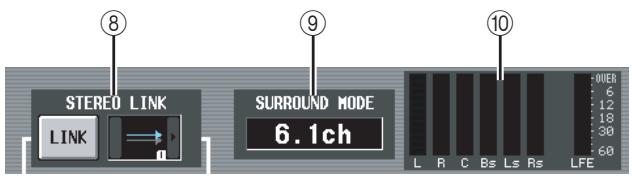
⑧ STEREO LINK
This specifies whether sound image movement will be linked between the two channels shown in the screen. To link the movement of the two channels, use the / buttons at left and right to select one of the eight link patterns. (For details on how each pattern will operate refer to p.146)
⑨ SURROUND MODE
This indicates the currently selected surround mode.
⑩ Level meters
These meters show the master levels of the surround buses.
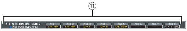
⑪ MIX SEND ASSIGNMENT
If MIX SEND is selected as the operation of the MIX section, this area indicates the surround parameters that can be operated by the MIX [ON] key and MIX encoder of the corresponding surround bus.
SURR VIEW (Surround view) screen
This screen shows the surround settings for each input channel. From this screen you can also jump to the SURR PARAM screen for the desired channel.
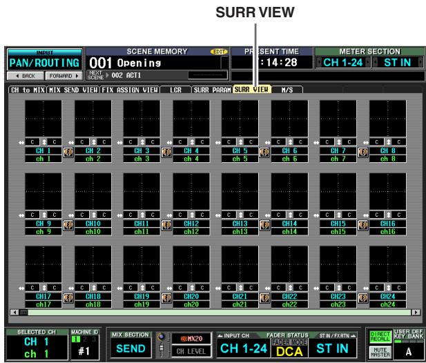
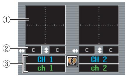
① Surround pan grid
For each input channel, the approximate surround pan position is shown by the O symbol. If you click this area, the SURR PARAM screen for that channel will appear.
② Surround pan position
This indicates the surround pan coordinate positions in the left/right direction (L/R) and the front/rear direction (F/R).
③ Channel
This is the number and name of the input channel.
M/S screen
For two adjacent odd-numbered/even-numbered input channels (or ST IN channel L/R), these settings convert the two-channel signal from an MS mic into L/R signals.
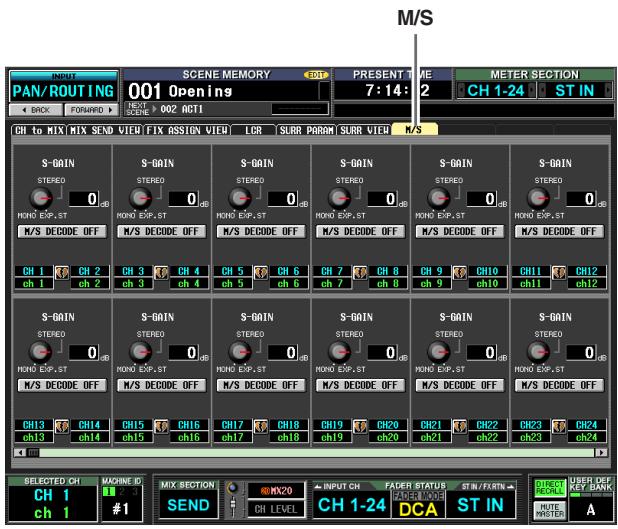
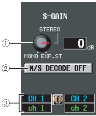
① S-GAIN knob
This knob sets the proportionate level of the S mic relative to the level of the M mic. The current value is shown in the numerical box at the right.
At the MONO position, the S mic level will be at - ,at the STEREO position the M mic and S mic will be at the same level, and at the EXP.ST position the S mic level will be +10 dB.
(2) M/S DECODE ON/OFF
This button switches M/S decoding on/off for two adjacent odd-numbered/even-numbered input channels (or ST IN channel L/R). M/S decoding can be switched on even for channels that are not assigned as a stereo pair.
③ Channel
This is the number and name of the input channel.
Hint
M/S is a stereo recording technique in which two microphones are used; a uni-directional M (Middle) mic and a bi-directional S (Side) mic. The M mic captures the main signal and the S mic captures the directional signal, and the sum (M + S) and difference (M - S) of the two signals (this procedure is known as "decoding") is recorded on the L and R channels respectively.
INPUT VIEW function
CH VIEW (Channel view) screen
This screen lists the mix parameters of the currently selected input channel. In this screen you can also edit the principal parameters and access other screens.
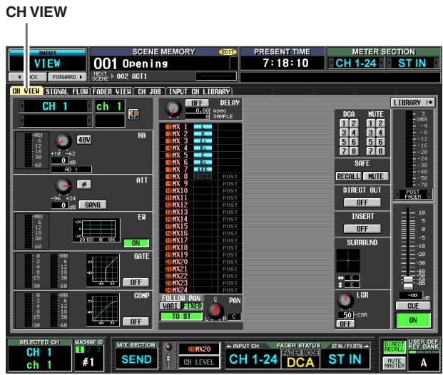
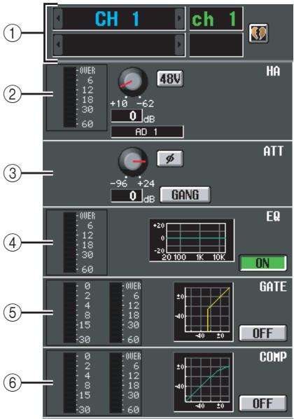
① Channel
This is the number of the input channel you are editing. If the input channel is paired (or if a ST IN channel is selected), a heart symbol is displayed at the right. You can click this symbol to enable/disable pairing for the input channel.
② HA (Head Amp)
This area indicates the input port that is patched to the input channel, the setting of the internal head amp (PM5D-RH model only) or external head amp, and the input level. In this screen you can also adjust the head amp gain and switch phantom power (+48V) on/off.
③ ATT (Attenuation)
This area shows the attenuation and (phase) settings. You can also adjust the attenuation and switch the phase from this screen.
(4) EQ
Refer to the explanation of the OUTPUT VIEW function CH VIEW screen (p.270).
⑤ GATE
This area shows the amount of gain reduction and the output level of the gate, a mini-graph showing the approximate response of the gate, and the gate on/off status. You can also switch the gate on/off from this screen. If you click the mini-graph, the GATE PARAM screen for that channel will appear.
⑥ COMP (Compressor)
Refer to the explanation of the OUTPUT VIEW function CH VIEW screen (p.270).
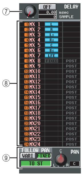
⑦ DELAY
In this area you can view and edit the delay time of the internal delay and its on/off status.
⑧ TO MIX
In this area you can specify the send level, output position, and on/off status of the signals sent from the corresponding input channel to MIX buses 1-24. (Operation is the same as in the TO MATRIX area of the OUTPUT VIEW function CH VIEW screen.) Refer to p.270.
TO STEREO
Here you can specify the on/off status, pan, and FOLLOW PAN settings of the signal sent from the corresponding input channel to the STEREO bus.
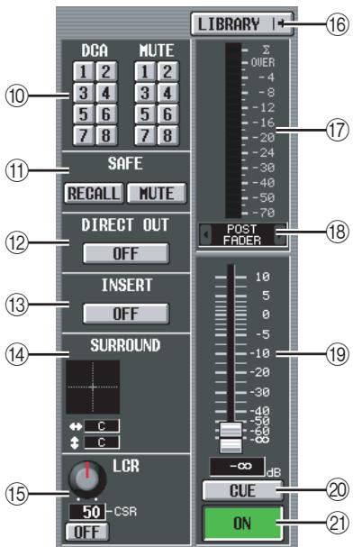
DCA group / Mute group
11 Recall safe / Mute safe
Refer to the explanation of the OUTPUT VIEW function CH VIEW screen (p.271).
12 DIRECT
Turns direct output on/off for the corresponding input channel.
(13) INSERT
Turns insert on/off for the corresponding input channel.
14 SURROUND (Surround pan)
If surround mode is enabled, the surround pan position of the corresponding input channel is indicated by the O symbol in the surround pan grid and also as a front/rear/left/right coordinate position. If you click the surround pan grid, the SURR PARAM screen for that channel will appear.
⑤ LCR
Here you can switch LCR mode on/off, and adjust CSR (the level of the CENTER channel relative to the L/R channels) ( p.267).
16 LIBRARY
This button accesses the INPUT CH LIBRARY screen ( p.316), where you can store/recall input channel library settings.
17 Level meter
This level meter indicates the input level of the channel.
18 Signal detection point
This is the point at which the signal level shown in the level meter (⑦) is detected (PRE ATT, PRE GATE, PRE FADER, POST FADER, or POST ON). You can edit this setting by clicking the / buttons at the left and right.
19 Fader
This controls the input level of the channel.
② CUE
② ON/OFF (Channel on/off)
Refer to the explanation of the OUTPUT VIEW function CH VIEW screen (p.271).
SIGNAL FLOW screen
This screen shows the signal flow for two adjacent odd-numbered/even-numbered input channels or ST IN channels. In this screen you can also edit some of the parameters, and access other screens. You can also determine the location within the signal flow at which clipping occurred.
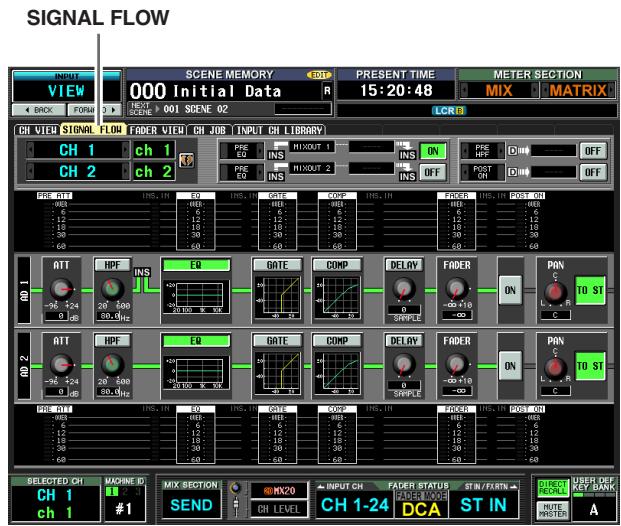
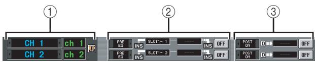
① Channel
② Insert
Except for the fact that this screen depicts input channels, the contents are the same as the OUTPUT VIEW function SIGNAL FLOW screen. Refer to p.272.
③ Direct out
This area displays information about the direct output of the two selected channels (the signal output position, the port patched to direct out, and the direct output on/off status).
Here you can also select the signal output position (use the / buttons at left and right), and switch direct output on/off (use the ON/OFF button).
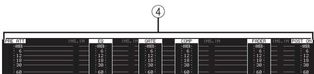
(4) Level meters
These meters indicate the levels at various points in the signal flow. Levels are detected at the following locations.
- PRE ATT (immediately before the attenuator)
EQ (immediately before and after the EQ)
GATE (immediately before and after the gate) - COMP (immediately before and after the compressor)
-
FADER (immediately before and after the fader)
-
POST ON (immediately after the CH [ON] key)
- INSERT IN (immediately after the insert point)
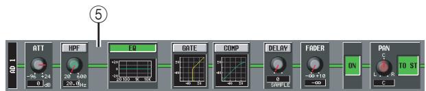
⑤ Signal flow
This area indicates the signal flow of the selected channel. The following parameters are displayed.
ATT (Attenuation)
Specifies the amount of attenuation immediately after AD conversion for the corresponding channel.
HPF (High Pass Filter)
Specifies the high pass filter on/off and cutoff frequency for the corresponding channel.
EQ (Equalizer)
GATE
COMP (Compressor)
These areas show the approximate response of the equalizer, gate, and compressor for the corresponding channel. You can also switch these on/off in this screen, or click a mini-graph to access the individual parameter screen.
- DELAY
Here you can switch the internal delay on/off and edit the delay time.
- FADER
This indicates the input level of the channel. This is linked with the encoder or fader of the corresponding channel.
- ON/OFF (On/off)
Turns the channel on/off. This is linked with the [ON] key of the corresponding channel.
TO STEREO
Here you can specify the on/off status and pan settings of the signal sent from the corresponding channel to the STEREO bus. These are linked with the [TO STREO] key and STEREO [PAN] encoder of the corresponding channel.
Hint
- If insert or direct out is turned on, the current insert point or direct out point within the signal flow is shown.
- If the signal clips, the signal flow (horizontal line) after clipping is displayed in red. If an output is turned off so that the signal does not flow any further, the subsequent flow is displayed in gray. If PEAK HOLD is on, the flow indication will stay red if clipping occurs even once, making it easier to see that clipping has occurred.
FADER VIEW screen
This screen shows the on/off status, level, and cue monitor status of the input channels and DCA groups.
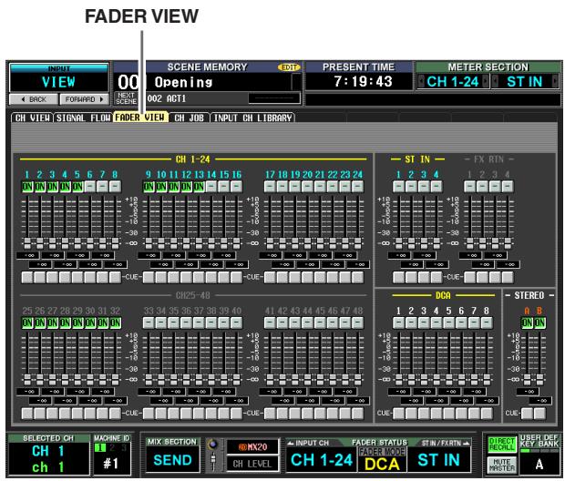
Except for the fact that this screen is for input channels, DCA groups, and STEREO A/B channels, this is the same as the OUTPUT VIEW function FADER VIEW screen. Refer to p.273.
CH JOB screen
In this screen you can copy the desired parameter(s) from the selected input channel into a memory buffer, and paste or move them to the same type of channel (you may select more than one paste-destination).
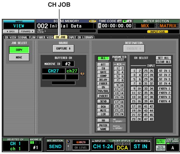
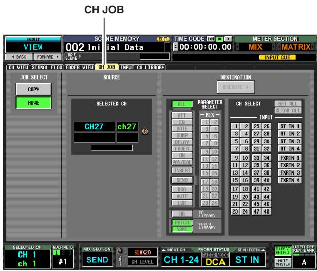
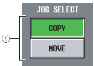
① JOB SELECT
Here you can select either Copy or Move as the operation.
COPY
The copy-source channel will remain; its parameters will be copied to another channel.
- MOVE
The parameters will be moved to another channel.
Note
When you execute the channel move operation, the channels between the selected channel and the move-destination channel will also move forward or backward.
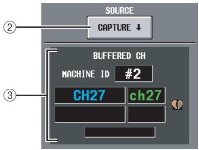
(2) CAPTURE
When you click this button, the settings of the currently selected channel will be copied to a temporary memory buffer. If you selected the MOVE operation, this will be grayed, and copying will not be possible.
If the corresponding INPUT channel is paired (or if a ST IN/FX RTN channel is selected), a heart symbol is shown at the right.
③ BUFFERED CH (Channel in the buffer)
This shows the channel that is currently copied into buffer memory. If you selected the MOVE operation, this will be grayed.
Note
- The same buffer memory is used to copy channel settings for both input channels and output channels.
- If output channel settings have been copied to the buffer memory, a message of "TYPE CONFLICT!" is displayed below, and you cannot paste to an input channel.
- The contents of the buffer memory are erased when the PM5D is powered-off.
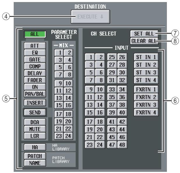
(4) EXECUTE
When you click this button, the specified parameters will be copied from buffer memory to the specified paste-destination channel. If you click this button when performing a MOVE operation, the parameters of the selected channel will be moved to the specified move-destination channel.
If an output channel is copied to buffer memory, or if no paste-destination has been specified, this is grayed-out and the Paste operation is unavailable.
Note
- A single channel can be moved only if the following two conditions are satisfied.
- There are no paired channels between the move-source and move-destination.
-
You have not selected a parameter of which only one exists for every two adjacent odd-numbered/even-numbered channels, such as DELAY GANG.
-
Channels can be moved only within the following channel sections (on each machine)
INPUT channels 1-48
- STIN channels 1-4
- FX RTN channels1-4
(5) PARAMETER SELECT
Here you can select the parameter(s) that will be pasted. You can't select this for the MOVE operation. You can select the following parameters.
| ALL | All parameters |
| ATT | Attenuator settings |
| EQ | EQ function settings |
| COMP | COMP function settings |
| DELAY | DELAY function settings |
| FADER | Fader level |
| ON | CH [ON] key on/off status |
| PAN/BAL | Pan/balance settings |
| INSERT | Insert on/off status and insert point |
| SEND | Send level to the desired MIX bus(es) |
| DCA | Associated DCA group |
| MUTE | Associated mute group |
| LCR | LCR screen settings |
| HA | HA library settings |
| PATCH | Input patch settings |
| NAME | Channel name |
If the SEND button is on, use the MIX buttons (1-24) to select the target MIX bus.
⑥ CH SELECT (Channel selection)
Here you can select the paste/move-destination channel(s). You can only select channels of the same type as the copy/move-source.
Hint
If the copy/move-source INPUT channel is paired, the odd-numbered channel is copied to the odd-numbered channel(s), and the even-numbered channel is copied to the even-numbered channel(s).
⑦ SET ALL
Specifies the paste-destination as all channels of the same type as the copy-source. You can't select this for the MOVE operation.
(8) CLEAR ALL
De-selects all channels. You can't select this for the MOVE operation.
INPUT CH LIBRARY (Input channel library) screen
Here you can recall, store, rename, or delete items in the input channel library.
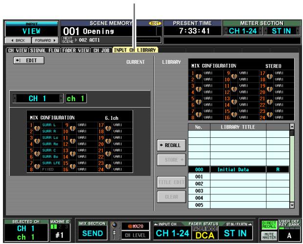
INPUT CH LIBRARY
Except for the fact that these settings are for input channels, this is the same as the OUTPUT VIEW function CH LIBRARY screen. Refer to p.275.
Appendices
EQ Library List
| # | Title | Parameter | ||||
| LOW | L-MID | H-MID | HIGH | |||
| 01 | Bass Drum 1 | PEAKING | PEAKING | PEAKING | H.SHELF | |
| G | +3.5 dB | -3.5 dB | 0.0 dB | +4.0 dB | ||
| F | 100 Hz | 265 Hz | 1.06 kHz | 5.30 kHz | ||
| Q | 1.25 | 10.0 | 0.90 | — | ||
| 02 | Bass Drum 2 | PEAKING | PEAKING | PEAKING | LPF | |
| G | +8.0 dB | -7.0 dB | +6.0 dB | ON | ||
| F | 80.0 Hz | 400 Hz | 2.50 kHz | 12.5 kHz | ||
| Q | 1.4 | 4.5 | 2.2 | — | ||
| 03 | Snare Drum 1 | PEAKING | PEAKING | PEAKING | H.SHELF | |
| G | -0.5 dB | 0.0 dB | +3.0 dB | +4.5 dB | ||
| F | 132 Hz | 1.00 kHz | 3.15 kHz | 5.00 kHz | ||
| Q | 1.25 | 4.5 | 0.11 | — | ||
| 04 | Snare Drum 2 | L.SHELF | PEAKING | PEAKING | PEAKING | |
| G | +1.5 dB | -8.5 dB | +2.5 dB | +4.0 dB | ||
| F | 180 Hz | 335 Hz | 2.36 kHz | 4.00 kHz | ||
| Q | — | 10.0 | 0.70 | 0.10 | ||
| 05 | Tom-tom 1 | PEAKING | PEAKING | PEAKING | PEAKING | |
| G | +2.0 dB | -7.5 dB | +2.0 dB | +1.0 dB | ||
| F | 212 Hz | 670 Hz | 4.50 kHz | 6.30 kHz | ||
| Q | 1.4 | 10.0 | 1.25 | 0.28 | ||
| 06 | Cymbal | L.SHELF | PEAKING | PEAKING | H.SHELF | |
| G | -2.0 dB | 0.0 dB | 0.0 dB | +3.0 dB | ||
| F | 106 Hz | 425 Hz | 1.06 kHz | 13.2 kHz | ||
| Q | — | 8.0 | 0.90 | — | ||
| 07 | High Hat | L.SHELF | PEAKING | PEAKING | H.SHELF | |
| G | -4.0 dB | -2.5 dB | +1.0 dB | +0.5 dB | ||
| F | 95 Hz | 425 Hz | 2.80 kHz | 7.50 kHz | ||
| Q | — | 0.50 | 1.0 | — | ||
| 08 | Percussion | L.SHELF | PEAKING | PEAKING | H.SHELF | |
| G | -4.5 dB | 0.0 dB | +2.0 dB | 0.0 dB | ||
| F | 100 Hz | 400 Hz | 2.80 kHz | 17.0 kHz | ||
| Q | — | 4.5 | 0.56 | — | ||
| 09 | E. Bass 1 | L.SHELF | PEAKING | PEAKING | H.SHELF | |
| G | -7.5 dB | +4.5 dB | +2.5 dB | 0.0 dB | ||
| F | 35.5 Hz | 112 Hz | 2.00 kHz | 4.00 kHz | ||
| Q | — | 5.0 | 4.5 | — | ||
| 10 | E. Bass 2 | PEAKING | PEAKING | PEAKING | H.SHELF | |
| G | +3.0 dB | 0.0 dB | +2.5 dB | +0.5 dB | ||
| F | 112 Hz | 112 Hz | 2.24 kHz | 4.00 kHz | ||
| Q | 0.10 | 5.0 | 6.3 | — | ||
| 11 | Syn. Bass 1 | PEAKING | PEAKING | PEAKING | H.SHELF | |
| G | +3.5 dB | +8.5 dB | 0.0 dB | 0.0 dB | ||
| F | 85 Hz | 950 Hz | 4.00 kHz | 12.5 kHz | ||
| Q | 0.10 | 8.0 | 4.5 | — | ||
| 12 | Syn. Bass 2 | PEAKING | PEAKING | PEAKING | H.SHELF | |
| G | +2.5 dB | 0.0 dB | +1.5 dB | 0.0 dB | ||
| F | 125 Hz | 180 Hz | 1.12 kHz | 12.5 kHz | ||
| Q | 1.6 | 8.0 | 2.2 | — | ||
| 13 | Piano 1 | L.SHELF | PEAKING | PEAKING | H.SHELF | |
| G | -6.0 dB | 0.0 dB | +2.0 dB | +4.0 dB | ||
| F | 95 Hz | 950 Hz | 3.15 kHz | 7.50 kHz | ||
| Q | — | 8.0 | 0.90 | — | ||
| # | Title | Parameter | ||||
| LOW | L-MID | H-MID | HIGH | |||
| 14 | Piano 2 | PEAKING | PEAKING | PEAKING | H.SHELF | |
| G | +3.5 dB | -8.5 dB | +1.5 dB | +3.0 dB | ||
| F | 224 Hz | 600 Hz | 3.15 kHz | 5.30 kHz | ||
| Q | 5.6 | 10.0 | 0.70 | — | ||
| 15 | E. G. Clean | PEAKING | PEAKING | PEAKING | H.SHELF | |
| G | +2.0 dB | -5.5 dB | +0.5 dB | +2.5 dB | ||
| F | 265 Hz | 400 Hz | 1.32 kHz | 4.50 kHz | ||
| Q | 0.18 | 10.0 | 6.3 | — | ||
| 16 | E. G. Crunch 1 | PEAKING | PEAKING | PEAKING | PEAKING | |
| G | +4.5 dB | 0.0 dB | +4.0 dB | +2.0 dB | ||
| F | 140 Hz | 1.00 kHz | 1.90 kHz | 5.60 kHz | ||
| Q | 8.0 | 4.5 | 0.63 | 9.0 | ||
| 17 | E. G. Crunch 2 | PEAKING | PEAKING | PEAKING | H.SHELF | |
| G | +2.5 dB | +1.5 dB | +2.5 dB | 0.0 dB | ||
| F | 125 Hz | 450 Hz | 3.35 kHz | 19.0 kHz | ||
| Q | 8.0 | 0.40 | 0.16 | — | ||
| 18 | E. G. Dist. 1 | L.SHELF | PEAKING | PEAKING | H.SHELF | |
| G | +5.0 dB | 0.0 dB | +3.5 dB | 0.0 dB | ||
| F | 355 Hz | 950 Hz | 3.35 kHz | 12.5 kHz | ||
| Q | — | 9.0 | 10.0 | — | ||
| 19 | E. G. Dist. 2 | L.SHELF | PEAKING | PEAKING | H.SHELF | |
| G | +6.0 dB | -8.5 dB | +4.5 dB | +4.0 dB | ||
| F | 315 Hz | 1.06 kHz | 4.25 kHz | 12.5 kHz | ||
| Q | — | 10.0 | 4.0 | — | ||
| 20 | A. G. Stroke 1 | PEAKING | PEAKING | PEAKING | H.SHELF | |
| G | -2.0 dB | 0.0 dB | +1.0 dB | +4.0 dB | ||
| F | 106 Hz | 1.00 kHz | 1.90 kHz | 5.30 kHz | ||
| Q | 0.9 | 4.5 | 3.5 | — | ||
| 21 | A. G. Stroke 2 | L.SHELF | PEAKING | PEAKING | H.SHELF | |
| G | -3.5 dB | -2.0 dB | 0.0 dB | +2.0 dB | ||
| F | 300 Hz | 750 Hz | 2.00 kHz | 3.55 kHz | ||
| Q | — | 9.0 | 4.5 | — | ||
| 22 | A. G. Arpeg. 1 | L.SHELF | PEAKING | PEAKING | PEAKING | |
| G | -0.5 dB | 0.0 dB | 0.0 dB | +2.0 dB | ||
| F | 224 Hz | 1.00 kHz | 4.00 kHz | 6.70 kHz | ||
| Q | — | 4.5 | 4.5 | 0.125 | ||
| 23 | A. G. Arpeg. 2 | L.SHELF | PEAKING | PEAKING | H.SHELF | |
| G | 0.0 dB | -5.5 dB | 0.0 dB | +4.0 dB | ||
| F | 180 Hz | 355 Hz | 4.00 kHz | 4.25 kHz | ||
| Q | — | 7.0 | 4.5 | — | ||
| 24 | Brass Sec. | PEAKING | PEAKING | PEAKING | PEAKING | |
| G | -2.0 dB | -1.0 dB | +1.5 dB | +3.0 dB | ||
| F | 90 Hz | 850 Hz | 2.12 kHz | 4.50 kHz | ||
| Q | 2.8 | 2.0 | 0.70 | 7.0 | ||
| 25 | Male Vocal 1 | PEAKING | PEAKING | PEAKING | PEAKING | |
| G | -0.5 dB | 0.0 dB | +2.0 dB | +3.5 dB | ||
| F | 190 Hz | 1.00 kHz | 2.00 kHz | 6.70 kHz | ||
| Q | 0.11 | 4.5 | 0.56 | 0.11 | ||
| 26 | Male Vocal 2 | PEAKING | PEAKING | PEAKING | H.SHELF | |
| G | +2.0 dB | -5.0 dB | -2.5 dB | +4.0 dB | ||
| F | 170 Hz | 236 Hz | 2.65 kHz | 6.70 kHz | ||
| Q | 0.11 | 10.0 | 5.6 | — | ||
| LOW | L-MID | H-MID | HIGH | |||
| 27 | Female Vo. 1 | PEAKING | PEAKING | PEAKING | PEAKING | |
| G-1.0 dB | +1.0 dB | +1.5 dB | +2.0 dB | |||
| F 118 Hz | 400 Hz | 2.65 kHz | 6.00 kHz | |||
| Q 0.18 | 0.45 | 0.56 | 0.14 | |||
| 28 | Female Vo. 2 | L.SHELF | PEAKING | PEAKING | H.SHELF | |
| G-7.0 dB | +1.5 dB | +1.5 dB | +2.5 dB | |||
| F 112 Hz | 335 Hz | 2.00 kHz | 6.70 kHz | |||
| Q — | 0.16 | 0.20 | — | |||
| 29 | Chorus & Harmo | PEAKING | PEAKING | PEAKING | PEAKING | |
| G-2.0 dB | -1.0 dB | +1.5 dB | +3.0 dB | |||
| F 90.0 Hz | 850 Hz | 2.12 kHz | 4.50 kHz | |||
| Q 2.8 | 2.0 | 0.70 | 7.0 | |||
| 30 | Total EQ 1 | PEAKING | PEAKING | PEAKING | H.SHELF | |
| G-0.5 dB | 0.0 dB | +3.0 dB | +6.5 dB | |||
| F 95.0 Hz | 950 Hz | 2.12 kHz | 16.0 kHz | |||
| Q 7.0 | 2.2 | 5.6 | — | |||
| 31 | Total EQ 2 | PEAKING | PEAKING | PEAKING | H.SHELF | |
| G+4.0 dB | +1.5 dB | +2.0 dB | +6.0 dB | |||
| F 95 Hz | 750 Hz | 1.80 kHz | 18.0 kHz | |||
| Q 7.0 | 2.8 | 5.6 | — | |||
| 32 | Total EQ 3 | L.SHELF | PEAKING | PEAKING | H.SHELF | |
| G+1.5 dB | +0.5 dB | +2.0 dB | +4.0 dB | |||
| F 67.0 Hz | 850 Hz | 1.90 kHz | 15.0 kHz | |||
| Q — | 0.28 | 0.70 | — | |||
| 33 | Bass Drum 3 | PEAKING | PEAKING | PEAKING | PEAKING | |
| G+3.5 dB | -10.0 dB | +3.5 dB | 0.0 dB | |||
| F 118 Hz | 315 Hz | 4.25 kHz | 20.0 kHz | |||
| Q 2.0 | 10.0 | 0.40 | 0.40 | |||
| 34 | Snare Drum 3 | L.SHELF | PEAKING | PEAKING | PEAKING | |
| G 0.0 dB | +2.0 dB | +3.5 dB | 0.0 dB | |||
| F 224 Hz | 560 Hz | 4.25 kHz | 4.00 kHz | |||
| Q — | 4.5 | 2.8 | 0.10 | |||
| 35 | Tom-tom 2 | L.SHELF | PEAKING | PEAKING | H.SHELF | |
| G-9.0 dB | +1.5 dB | +2.0 dB | 0.0 dB | |||
| F 90.0 Hz | 212 Hz | 5.30 kHz | 17.0 kHz | |||
| Q — | 4.5 | 1.25 | — | |||
| 36 | Piano 3 | PEAKING | PEAKING | PEAKING | H.SHELF | |
| G+4.5 dB | -13.0 dB | +4.5 dB | +2.5 dB | |||
| F 100 Hz | 475 Hz | 2.36 kHz | 10.0 kHz | |||
| Q 8.0 | 10.0 | 9.0 | — | |||
| 37 | Piano Low | PEAKING | PEAKING | PEAKING | H.SHELF | |
| G-5.5 dB | +1.5 dB | +6.0 dB | 0.0 dB | |||
| F 190 Hz | 400 Hz | 6.70 kHz | 12.5 kHz | |||
| Q 10.0 | 6.3 | 2.2 | — | |||
| 38 | Piano High | PEAKING | PEAKING | PEAKING | PEAKING | |
| G-5.5 dB | +1.5 dB | +5.0 dB | +3.0 dB | |||
| F 190 Hz | 400 Hz | 6.70 kHz | 5.60 kHz | |||
| Q 10.0 | 6.3 | 2.2 | 0.10 | |||
| 39 | Fine-EQ Cass | L.SHELF | PEAKING | PEAKING | H.SHELF | |
| G-1.5 dB | 0.0 dB | +1.0 dB | +3.0 dB | |||
| F 75.0 Hz | 1.00 kHz | 4.00 kHz | 12.5 kHz | |||
| Q — | 4.5 | 1.8 | — | |||
| 40 | Narrator | PEAKING | PEAKING | PEAKING | H.SHELF | |
| G-4.0 dB | -1.0 dB | +2.0 dB | 0.0 dB | |||
| F 106 Hz | 710 Hz | 2.50 kHz | 10.0 kHz | |||
| Q 4.0 | 7.0 | 0.63 | — | |||
GATE Library List
| # | Title | Type | Parameter | Value |
| 1 | Gate | GATE | Threshold (dB) | -26 |
| Range (dB) | -56 | |||
| Attack (ms) | 0 | |||
| Hold (ms) | 2.56 | |||
| Decay (ms) | 331 | |||
| 2 | Ducking | DUCKING | Threshold (dB) | -19 |
| Range (dB) | -22 | |||
| Attack (ms) | 93 | |||
| Hold (ms) | 1.20 S | |||
| Decay (ms) | 6.32 S | |||
| 3 | A. Dr. BD | GATE | Threshold (dB) | -11 |
| Range (dB) | -53 | |||
| Attack (ms) | 0 | |||
| Hold (ms) | 1.93 | |||
| Decay (ms) | 400 | |||
| 4 | A. Dr. SN | GATE | Threshold (dB) | -8 |
| Range (dB) | -23 | |||
| Attack (ms) | 1 | |||
| Hold (ms) | 0.63 | |||
| Decay (ms) | 238 |
Compressor Library List
| # | Title | Type | Parameter | Value |
| 1 | Comp | COMP | Threshold (dB) | -8 |
| Ratio (:1) | 2.5 | |||
| Attack (ms) | 30 | |||
| Out gain (dB) | 0.0 | |||
| Knee | 2 | |||
| Release (ms) | 250 | |||
| 2 | Expand | EXPAND | Threshold (dB) | -23 |
| Ratio (:1) | 1.7 | |||
| Attack (ms) | 1 | |||
| Out gain (dB) | 3.5 | |||
| Knee | 2 | |||
| Release (ms) | 70 | |||
| 3 | Compander (H) | COMPAND-H | Threshold (dB) | -10 |
| Ratio (:1) | 3.5 | |||
| Attack (ms) | 1 | |||
| Out gain (dB) | 0.0 | |||
| Width (dB) | 6 | |||
| Release (ms) | 250 | |||
| 4 | Compander (S) | COMPAND-S | Threshold (dB) | -8 |
| Ratio (:1) | 4 | |||
| Attack (ms) | 25 | |||
| Out gain (dB) | 0.0 | |||
| Width (dB) | 24 | |||
| Release (ms) | 180 | |||
| 5 | A. Dr. BD | COMP | Threshold (dB) | -24 |
| Ratio (:1) | 3 | |||
| Attack (ms) | 9 | |||
| Out gain (dB) | 5.5 | |||
| Knee | 2 | |||
| Release (ms) | 58 | |||
| 6 | A. Dr. BD | COMPAND-H | Threshold (dB) | -11 |
| Ratio (:1) | 3.5 | |||
| Attack (ms) | 1 | |||
| Out gain (dB) | -1.5 | |||
| Width (dB) | 7 | |||
| Release (ms) | 192 | |||
| 7 | A. Dr. SN | COMP | Threshold (dB) | -17 |
| Ratio (:1) | 2.5 | |||
| Attack (ms) | 8 | |||
| Out gain (dB) | 3.5 | |||
| Knee | 2 | |||
| Release (ms) | 12 | |||
| 8 | A. Dr. SN | EXPAND | Threshold (dB) | -23 |
| Ratio (:1) | 2 | |||
| Attack (ms) | 0 | |||
| Out gain (dB) | 0.5 | |||
| Knee | 2 | |||
| Release (ms) | 151 | |||
| 9 | A. Dr. SN | COMPAND-S | Threshold (dB) | -8 |
| Ratio (:1) | 1.7 | |||
| Attack (ms) | 11 | |||
| Out gain (dB) | 0.0 | |||
| Width (dB) | 10 | |||
| Release (ms) | 128 | |||
| 10 | A. Dr. Tom | EXPAND | Threshold (dB) | -20 |
| Ratio (:1) | 2 | |||
| Attack (ms) | 2 | |||
| Out gain (dB) | 5.0 | |||
| Knee | 2 | |||
| Release (ms) | 749 |
| # | Title | Type | Parameter | Value |
| 11 | A. Dr. OverTop | COMPAND-S | Threshold (dB) | -24 |
| Ratio (:1) | 2 | |||
| Attack (ms) | 38 | |||
| Out gain (dB) | -3.5 | |||
| Width (dB) | 54 | |||
| Release (ms) | 842 | |||
| 12 | E. B. Finger | COMP | Threshold (dB) | -12 |
| Ratio (:1) | 2 | |||
| Attack (ms) | 15 | |||
| Out gain (dB) | 4.5 | |||
| Knee | 2 | |||
| Release (ms) | 470 | |||
| 13 | E. B. Slap | COMP | Threshold (dB) | -12 |
| Ratio (:1) | 1.7 | |||
| Attack (ms) | 6 | |||
| Out gain (dB) | 4.0 | |||
| Knee | hard | |||
| Release (ms) | 133 | |||
| 14 | Syn. Bass | COMP | Threshold (dB) | -10 |
| Ratio (:1) | 3.5 | |||
| Attack (ms) | 9 | |||
| Out gain (dB) | 3.0 | |||
| Knee | hard | |||
| Release (ms) | 250 | |||
| 15 | Piano1 | COMP | Threshold (dB) | -9 |
| Ratio (:1) | 2.5 | |||
| Attack (ms) | 17 | |||
| Out gain (dB) | 1.0 | |||
| Knee | hard | |||
| Release (ms) | 238 | |||
| 16 | Piano2 | COMP | Threshold (dB) | -18 |
| Ratio (:1) | 3.5 | |||
| Attack (ms) | 7 | |||
| Out gain (dB) | 6.0 | |||
| Knee | 2 | |||
| Release (ms) | 174 | |||
| 17 | E. Guitar | COMP | Threshold (dB) | -8 |
| Ratio (:1) | 3.5 | |||
| Attack (ms) | 7 | |||
| Out gain (dB) | 2.5 | |||
| Knee | 4 | |||
| Release (ms) | 261 | |||
| 18 | A. Guitar | COMP | Threshold (dB) | -10 |
| Ratio (:1) | 2.5 | |||
| Attack (ms) | 5 | |||
| Out gain (dB) | 1.5 | |||
| Knee | 2 | |||
| Release (ms) | 238 | |||
| 19 | Strings1 | COMP | Threshold (dB) | -11 |
| Ratio (:1) | 2 | |||
| Attack (ms) | 33 | |||
| Out gain (dB) | 1.5 | |||
| Knee | 2 | |||
| Release (ms) | 749 | |||
| 20 | Strings2 | COMP | Threshold (dB) | -12 |
| Ratio (:1) | 1.5 | |||
| Attack (ms) | 93 | |||
| Out gain (dB) | 1.5 | |||
| Knee | 4 | |||
| Release (ms) | 1.35 S | |||
| 21 | Strings3 | COMP | Threshold (dB) | -17 |
| Ratio (:1) | 1.5 | |||
| Attack (ms) | 76 | |||
| Out gain (dB) | 2.5 | |||
| Knee | 2 | |||
| Release (ms) | 186 | |||
| 22 | BrassSection | COMP | Threshold (dB) | -18 |
| Ratio (:1) | 1.7 | |||
| Attack (ms) | 18 | |||
| Out gain (dB) | 4.0 | |||
| Knee | 1 | |||
| Release (ms) | 226 | |||
| 23 | Syn. Pad | COMP | Threshold (dB) | -13 |
| Ratio (:1) | 2 | |||
| Attack (ms) | 58 | |||
| Out gain (dB) | 2.0 | |||
| Knee | 1 | |||
| Release (ms) | 238 | |||
| 24 | SamplingPerc | COMPAND-S | Threshold (dB) | -18 |
| Ratio (:1) | 1.7 | |||
| Attack (ms) | 8 | |||
| Out gain (dB) | -2.5 | |||
| Width (dB) | 18 | |||
| Release (ms) | 238 | |||
| 25 | Sampling BD | COMP | Threshold (dB) | -14 |
| Ratio (:1) | 2 | |||
| Attack (ms) | 2 | |||
| Out gain (dB) | 3.5 | |||
| Knee | 4 | |||
| Release (ms) | 35 | |||
| 26 | Sampling SN | COMP | Threshold (dB) | -18 |
| Ratio (:1) | 4 | |||
| Attack (ms) | 8 | |||
| Out gain (dB) | 8.0 | |||
| Knee | hard | |||
| Release (ms) | 354 | |||
| 27 | Hip Comp | COMPAND-S | Threshold (dB) | -23 |
| Ratio (:1) | 20 | |||
| Attack (ms) | 15 | |||
| Out gain (dB) | 0.0 | |||
| Width (dB) | 15 | |||
| Release (ms) | 163 | |||
| 28 | Solo Vocal1 | COMP | Threshold (dB) | -20 |
| Ratio (:1) | 2.5 | |||
| Attack (ms) | 31 | |||
| Out gain (dB) | 2.0 | |||
| Knee | 1 | |||
| Release (ms) | 342 | |||
| 29 | Solo Vocal2 | COMP | Threshold (dB) | -8 |
| Ratio (:1) | 2.5 | |||
| Attack (ms) | 26 | |||
| Out gain (dB) | 1.5 | |||
| Knee | 3 | |||
| Release (ms) | 331 | |||
| 30 | Chorus | COMP | Threshold (dB) | -9 |
| Ratio (:1) | 1.7 | |||
| Attack (ms) | 39 | |||
| Out gain (dB) | 2.5 | |||
| Knee | 2 | |||
| Release (ms) | 226 |
| # | Title | Type | Parameter | Value |
| 31 | Click Erase | EXPAND | Threshold (dB) | -33 |
| Ratio ( :1) | 2 | |||
| Attack (ms) | 1 | |||
| Out gain (dB) | 2.0 | |||
| Knee | 2 | |||
| Release (ms) | 284 | |||
| 32 | Announcer | COMPAND-H | Threshold (dB) | -14 |
| Ratio ( :1) | 2.5 | |||
| Attack (ms) | 1 | |||
| Out gain (dB) | -2.5 | |||
| Width (dB) | 18 | |||
| Release (ms) | 180 | |||
| 33 | Limiter1 | COMPAND-S | Threshold (dB) | -9 |
| Ratio ( :1) | 3 | |||
| Attack (ms) | 20 | |||
| Out gain (dB) | -3.0 | |||
| Width (dB) | 90 | |||
| Release (ms) | 3.91 s | |||
| 34 | Limiter2 | COMP | Threshold (dB) | 0 |
| Ratio ( :1) | ∞ | |||
| Attack (ms) | 0 | |||
| Out gain (dB) | 0.0 | |||
| Knee | hard | |||
| Release (ms) | 319 | |||
| 35 | Total Comp1 | COMP | Threshold (dB) | -18 |
| Ratio ( :1) | 3.5 | |||
| Attack (ms) | 94 | |||
| Out gain (dB) | 2.5 | |||
| Knee | hard | |||
| Release (ms) | 447 | |||
| 36 | Total Comp2 | COMP | Threshold (dB) | -16 |
| Ratio ( :1) | 6 | |||
| Attack (ms) | 11 | |||
| Out gain (dB) | 6.0 | |||
| Knee | 1 | |||
| Release (ms) | 180 |
- When fs=44.1 kHz
Each channel has a GATE section (input channels and ST IN channels only) and a COMP section. The Gate section includes Gate and Ducking types. The Comp section includes Compressor, Expander, Compander Hard (COMP. (H)), and Compander Soft (COMP. (S)) types.
GATE section
GATE
A gate attenuates signals below a set THRESHOLD level by a specified amount (RANGE).
| Parameter | Range | Description |
| THRESHOLD (dB) | -72 to 0 (73 points) | This determines the level at which the gate effect is applied. |
| RANGE (dB) | -∞, -69 to 0 (71 points) | This determines the amount of attenuation when the gate closes. |
| ATTACK (ms) | 0–120 (121 points) | This determines how fast the gate opens when the signal exceeds the threshold level. |
| HOLD (ms) | 44.1kHz: 0.02 ms – 2.13 sec48kHz: 0.02 ms – 1.96 sec88.2kHz: 0.01 ms – 1.06 sec96kHz: 0.01 ms – 981 ms (160 points) | This determines how long the gate stays open once the trigger signal has fallen below the threshold. |
| DECAY (ms) | 44.1kHz: 6 ms – 46.0 sec48kHz: 5 ms – 42.3 sec88.2kHz: 3 ms – 23.0 sec96kHz: 3 ms – 21.1 sec (160 points) | This determines how fast the gate closes once the hold time has expired. The value is expressed as the duration required for the level to change by 6 dB. |
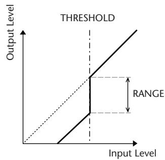
I/O Characteristics
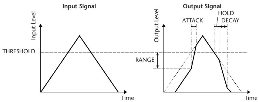
Time Series Analysis
DUCKING
Ducking is commonly used for voice-over applications in which the background music level is reduced automatically when an annunciers speaks. When the KEY IN source signal level exceeds the specified THRESHOLD, the output level is attenuated by a specified amount (RANGE).
| Parameter | Range | Description |
| THRESHOLD (dB) | -54 to 0 (55 points) | This determines the level of trigger signal (KEY IN) required to activate ducking. |
| RANGE (dB) | -70 to 0 (71 points) | This determines the amount of attenuation when ducking is activated. |
| ATTACK (ms) | 0–120 (121 points) | This determines how soon the signal is ducked once the ducker has been triggered. |
| HOLD (ms) | 44.1kHz: 0.02 ms – 2.13 sec48kHz: 0.02 ms – 1.96 sec88.2kHz: 0.01 ms – 1.06 sec96kHz: 0.01 ms – 981 ms (160 points) | This determines how long ducking remains active once the trigger signal has fallen below the THRESHOLD level. |
| DECAY (ms) | 44.1kHz: 6 ms – 46.0 sec48kHz: 5 ms – 42.3 sec88.2kHz: 3 ms – 23.0 sec96kHz: 3 ms – 21.1 sec (160 points) | This determines how soon the ducker returns to its normal gain once the trigger signal level drops below the threshold. The value is expressed as the duration required for the level to change by 6 dB. |
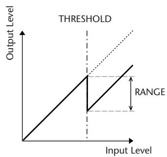
I/O Characteristics
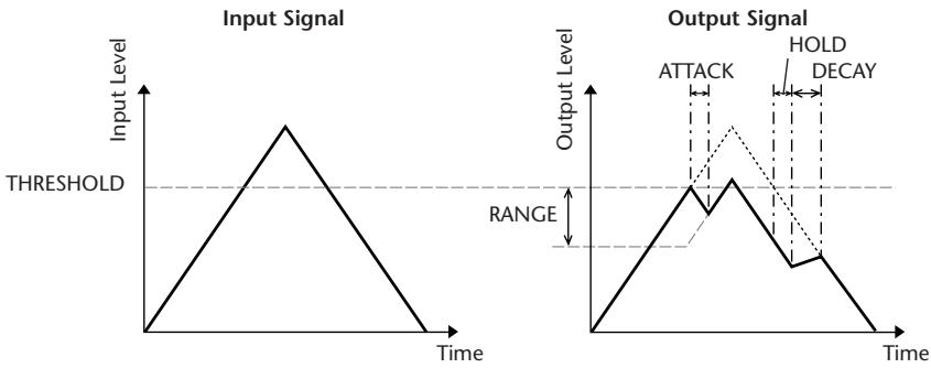
Time Series Analysis
COMP section
Compressor (COMP)
The COMP processor attenuates signals above a specified THRESHOLD by a specified RATIO. The COMP processor can also be used as a limiter, which, with a RATIO of :1 , reduces the level to the threshold. This means that the limiter's output level never actually exceeds the threshold.
| Parameter | Range | Description |
| THRESHOLD (dB) | -54 to 0 (55 points) | This determines the level of input signal required to trigger the compressor. |
| RATIO | 1.0:1, 1.1:1, 1.3:1, 1.5:1, 1.7:1, 2.0:1, 2.5:1, 3.0:1, 3.5:1, 4.0:1, 5.0:1, 6.0:1, 8.0:1, 10:1, 20:1, ∞:1 (16 points) | This determines the amount of compression, that is, the change in output signal level relative to change in input signal level. |
| ATTACK (ms) | 0–120 (121 points) | This determines how soon the signal will be compressed once the compressor has been triggered. |
| RELEASE (ms) | 44.1kHz: 6 ms – 46.0 sec48kHz: 5 ms – 42.3 sec88.2kHz: 3 ms – 23.0 sec96kHz: 3 ms – 21.1 sec (160 points) | This determines how soon the compressor returns to its normal gain once the trigger signal level drops below the threshold. The value is expressed as the duration required for the level to change by 6 dB. |
| OUT GAIN (dB) | 0.0 to +18.0 (181 points) | This sets the compressor's output signal level. |
| KNEE | Hard, 1–5 (6 points) | This determines how compression is applied at the threshold. For higher knee settings, compression is applied gradually as the signal exceeds the specified threshold, creating a more natural sound. |
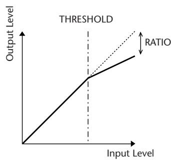
I/O Characteristics (KNEE= hard, OUT GAIN=0.0dB)
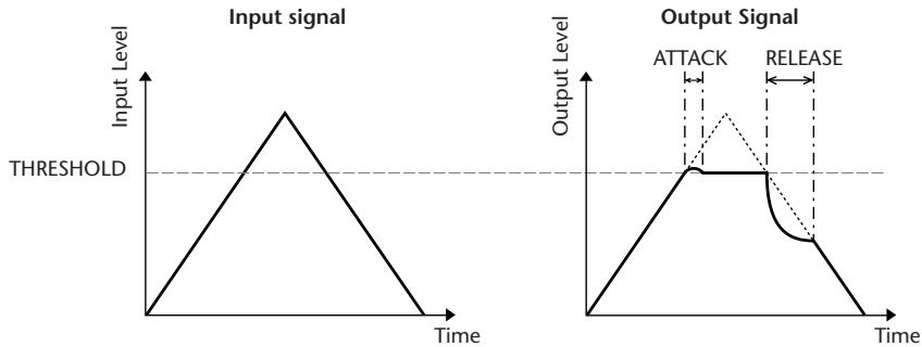
Time Series Analysis (RATIO=∞:1)
Expander (EXPAND)
An expander attenuates signals below a specified THRESHOLD by a specified RATIO.
| Parameter | Range | Description |
| THRESHOLD (dB) | -54 to 0 (55 points) | This determines the level of input signal required to trigger the expander. |
| RATIO | 1.0:1, 1.1:1, 1.3:1, 1.5:1, 1.7:1, 2.0:1, 2.5:1, 3.0:1, 3.5:1, 4.0:1, 5.0:1, 6.0:1, 8.0:1, 10:1, 20:1, ∞:1 (16 points) | This determines the amount of expansion. |
| ATTACK (ms) | 0–120 (121 points) | This determines how soon the expander returns to its normal gain once the trigger signal level exceeds the threshold. |
| RELEASE (ms) | 44.1kHz: 6 ms – 46.0 sec48kHz: 5 ms – 42.3 sec88.2kHz: 3 ms – 23.0 sec96kHz: 3 ms – 21.1 sec (160 points) | This determines how soon the signal is expanded once the signal level drops below the threshold. The value is expressed as the duration required for the level to change by 6 dB. |
| OUT GAIN (dB) | 0.0 to +18.0 (181 points) | This sets the expander's output signal level. |
| KNEE | Hard, 1–5 (6 points) | This determines how expansion is applied at the threshold. For higher knee settings, expansion is applied gradually as the signal falls below the specified threshold, creating a more natural sound. |
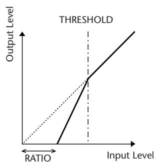
I/O Characteristics (KNEE= hard, OUT GAIN= 0.0dB)
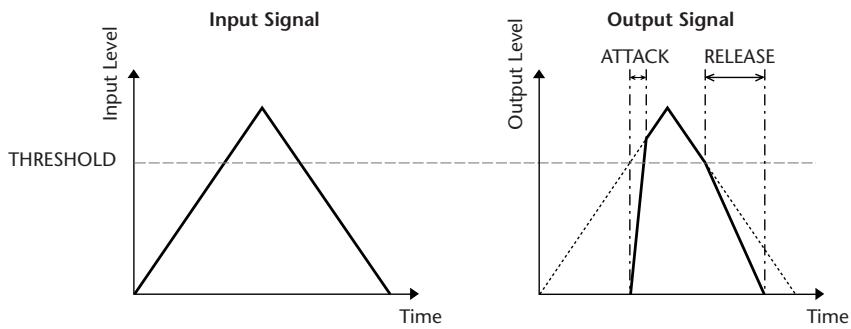
Time Series Analysis (RATIO=∞:1)
COMPANDER HARD (COMP.(H))
COMPANDER SOFT (COMP.(S))
The hard and soft companders combine the effects of the compressor, expander and limiter.
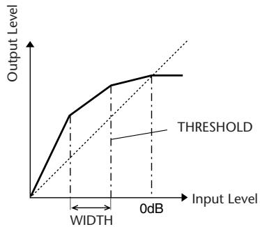
The companders function differently at the following levels:
① 0 dB and higher . Functions as a limiter.
(2) Exceeding the threshold Functions as a compressor.
③ Below the threshold and width .... Functions as an expander.
The hard compander has an expansion ratio of 5:1, while the soft compander has an expansion ratio of 1.5:1. The expander is essentially turned off when the width is set to maximum. The compressor has a fixed knee setting of 2.
- The gain is automatically adjusted according to the ratio and threshold values, and can be increased by up to 18 dB.
- The OUT GAIN parameter enables you to compensate for the overall level change caused by the compression and expansion processes.
| Parameter | Range | Description |
| THRESHOLD (dB) | -54 to 0 (55 points) | This determines the level at which compression is applied. |
| RATIO | 1.0:1, 1.1:1, 1.3:1, 1.5:1, 1.7:1, 2.0:1, 2.5:1, 3.0:1, 3.5:1, 4.0:1, 5.0:1, 6.0:1, 8.0:1, 10:1, 20:1, (15 points) | This determines the amount of compression. |
| ATTACK (ms) | 0–120 (121 points) | This determines how soon the signal is compressed or expanded once the comp- ander has been triggered. |
| RELEASE (ms) | 44.1kHz: 6 ms – 46.0 sec 48kHz: 5 ms – 42.3 sec 88.2kHz: 3 ms – 23.0 sec 96kHz: 3 ms – 21.1 sec (160 points) | This determines how soon the compressor or expander returns to the normal gain once the trigger signal level drops below or exceeds the threshold respectively. The value is expressed as the duration required for the level to change by 6 dB. |
| OUT GAIN (dB) | -18.0 to 0.0 (181 points) | This sets the compander's output signal level. |
| WIDTH (dB) | 1–90 (90 points) | This determines how far below the threshold expansion will be applied. The expander is activated when the level drops below the threshold and width. |
Effect Library List
This is a list of the built-in effects.
| No. | Title | Type | Description |
| 001 | Reverb Hall | REVERB HALL | Concert hall reverberation simulation with gate |
| 002 | Reverb Room | REVERB ROOM | Room reverberation simulation with gate |
| 003 | Reverb Stage | REVERB STAGE | Reverb designed for vocals, with gate |
| 004 | Reverb Plate | REVERB PLATE | Plate reverb simulation with gate |
| 005 | Early Ref. | EARLY REF. | Early reflections without the subsequent reverb |
| 006 | Gate Reverb | GATE REVERB | Gated early reflections |
| 007 | Reverse Gate | REVERSE GATE | Gated reverse early reflections |
| 008 | Mono Delay | MONO DELAY | Simple mono delay |
| 009 | Stereo Delay | STEREO DELAY | Simple stereo delay |
| 010 | ModDELAY | MOD.DELAY | Simple repeat delay with modulation |
| 011 | Delay LCR | DELAY LCR | 3-tap (left, center, right) delay |
| 012 | Echo | ECHO | Stereo delay with crossed left/right feedback |
| 013 | Chorus | CHORUS | Chorus |
| 014 | Flange | FLANGE | Flanger |
| 015 | Symphonic | SYMPHONIC | Proprietary Yamaha effect that produces a richer and more complex modulation than normal chorus |
| 016 | Phaser | PHASER | 16-stage stereo phase shifter |
| 017 | Auto Pan | AUTO PAN | Auto-panner |
| 018 | Tremolo | TREMOLO | Tremolo |
| 019 | HQ. Pitch | HQ.PITCH | Mono pitch shifter, producing stable results |
| 020 | Dual Pitch | DUAL PITCH | Stereo pitch shifter |
| 021 | Rotary | ROTARY | Rotary speaker simulation |
| 022 | Ring Mod. | RING MOD. | Ring modulator |
| 023 | Mod.Filter | MOD.FILTER | Modulated filter |
| 024 | Distortion | DISTORTION | Distortion |
| 025 | Amp Simulate | AMP SIMULATE | Guitar amp simulation |
| 026 | Dyna.Filter | DYNA FILTER | Dynamically controlled filter |
| 027 | Dyna.Flange | DYNA.FLANGE | Dynamically controlled flanger |
| 028 | Dyna.Phaser | DYNA.PHASER | Dynamically controlled phase shifter |
| 029 | Rev+Chorus | REV+CHORUS | Reverb and chorus in parallel |
| 030 | Rev→Chorus | REV→CHORUS | Reverb and chorus in series |
| 031 | Rev+Flange | REV+FLANGE | Reverb and flanger in parallel |
| 032 | Rev→Flange | REV→FLANGE | Reverb and flanger in series |
| 033 | Rev+Sympho. | REV+SYMPHO. | Reverb and symphonic in parallel |
| 034 | Rev→Sympho. | REV→SYMPHO. | Reverb and symphonic in series |
| 035 | Rev→Pan | REV→PAN | Reverb and auto-pan in series |
| 036 | Delay+Er. | DELAY+ER. | Delay and early reflections in parallel |
| 037 | Delay+Er. | DELAY→ER. | Delay and early reflections in series |
| 038 | Delay+Rev | DELAY+REV | Delay and reverb in parallel |
| 039 | Delay→Rev | DELAY→REV | Delay and reverb in series |
| 040 | Dist→Delay | DIST→DELAY | Distortion and delay in series |
| No. | Title | Type | Description |
| 041 | Multi.Filter | MULTI_FILTER | 3-band parallel filter (24 dB/octave) |
| 042 | Freeze | FREEZE | Simple sampler |
| 043 | Stereo Reverb | ST REVERB | Stereo reverb |
| 044 | M.Band Dyna. | M.BAND DYNA. | Multi-band dynamics pro-cessor |
| 045 | M.Band Comp | M.BAND COMP | Multi-band compressor |
| 046 | REV-X Hall | REV-X HALL | New reverb algorithm that delivers dense and rich reverberation, smooth decay, and provides a spaciously and depth that enhances the original sound. Choose from three types depending on your location and needs; REV-X HALL, REV-X ROOM, and REV-X PLATE. |
| 047 | REV-X Room | REV-X ROOM | |
| 048 | REV-X Plate | REV-X PLATE | |
| 049 | Comp276 | COMP276 | This compressor emulates the characteristics of an analog compressor that has become a sought-after classic in recording studios. |
| 050 | Comp276S | COMP276S | This is a stereo model of COMP276. |
| 051 | Comp260 | COMP260 | This compressor emulates the characteristics of a compressor/limiter of the latter 1970s that has become a sought-after classic for live SR. |
| 052 | Comp260S | COMP260S | This is a stereo model of the COMP260. |
| 053 | Equalizer601 | EQUALIZER601 | This equalizer emulates the characteristics of an analog equalizer of the 1970s. It can be used to obtain a sense of drive. |
| 054 | OpenDeck | OPENDECK | This is a tape saturation effect that emulates the tape compression produced by two open-reel tape recorders: a recording deck and a reproduction deck. |
| 055 | De-Esser | DE-ESSER | This detects and compresses only the high-frequency consonant portions such as the sibulance of a vocal. |
REVERB HALL, REVERB ROOM, REVERB STAGE, REVERB PLATE
One input, two output hall, room, stage, and plate reverb simulations, all with gates.
| Parameter | Range | Description |
| REV TIME | 0.3–99.0 s | Reverb time |
| INI. DLY | 0.0–500.0 ms | Initial delay before reverb begins |
| HI. RATIO | 0.1–1.0 | High-frequency reverb time ratio |
| LO. RATIO | 0.1–2.4 | Low-frequency reverb time ratio |
| DIFF. | 0–10 | Reverb diffusion (left–right reverb spread) |
| DENSITY | 0–100% | Reverb density |
| E/R DLY | 0.0–100.0 ms | Delay between early reflections and reverb |
| E/R BAL. | 0–100% | Balance of early reflections and reverb (0% = all reverb, 100% = all early reflections) |
| HPF | THRU, 21.2 Hz–8.00 kHz | High-pass filter cutoff frequency |
| LPF | 50.0 Hz–16.0 kHz, THRU | Low-pass filter cutoff frequency |
| GATE LVL | OFF, –60 to 0 dB | Level at which gate kicks in |
| ATTACK | 0–120 ms | Gate opening speed |
| HOLD | *1 | Gate open time |
| DECAY | *2 | Gate closing speed |
1. 0.02 ms-2.13 s (fs=44.1 kHz), 0.02 ms-1.96 s (fs=48 kHz), 0.01 ms-1.06 s (fs=88.2 kHz), 0.01 ms-981 ms (fs=96 kHz)
2. 6.0 ms-46.0 s (fs=44.1 kHz), 5.0 ms-42.3 s (fs=48 kHz), 3 ms-23.0 s (fs=88.2 kHz), 3 ms-21.1 s (fs=96 kHz)
EARLY REF.
One input, two output early reflections.
| Parameter | Range | Description |
| TYPE | S-Hall, L-Hall, Random, Revers, Plate, Spring | Type of early reflection sim-ulation |
| ROOMSIZE | 0.1–20.0 | Reflection spacing |
| LIVENESS | 0–10 | Early reflections decay char-acteristics (0 = dead, 10 = live) |
| INI. DLY | 0.0–500.0 ms | Initial delay before reverb begins |
| DIFF. | 0–10 | Reflection diffusion (left-right reflection spread) |
| DENSITY | 0–100% | Reflection density |
| ER NUM. | 1–19 | Number of early reflections |
| FB GAIN | -99 to +99% | Feedback gain |
| HI. RATIO | 0.1–1.0 | High-frequency feedback ratio |
| HPF | THRU, 21.2 Hz–8.00 kHz | High-pass filter cutoff fre-quency |
| LPF | 50.0 Hz–16.0 kHz, THRU | Low-pass filter cutoff fre-quency |
GATE REVERB, REVERSE GATE
One input, two output early reflections with gate, and early reflections with reverse gate.
| Parameter | Range | Description |
| TYPE | Type-A, Type-B | Type of early reflection simulation |
| ROOMSIZE | 0.1–20.0 | Reflection spacing |
| LIVENESS | 0–10 | Early reflections decay characteristics (0 = dead, 10 = live) |
| INI. DLY | 0.0–500.0 ms | Initial delay before reverb begins |
| DIFF. | 0–10 | Reflection diffusion (left–right reflection spread) |
| DENSITY | 0–100% | Reflection density |
| HI. RATIO | 0.1–1.0 | High-frequency feedback ratio |
| ER NUM. | 1–19 | Number of early reflections |
| FB GAIN | -99 to +99% | Feedback gain |
| HPF | THRU, 21.2 Hz–8.00 kHz | High-pass filter cutoff frequency |
| LPF | 50.0 Hz–16.0 kHz, THRU | Low-pass filter cutoff frequency |
MONO DELAY
One input, one output basic repeat delay.
| Parameter | Range | Description |
| DELAY | 0.0–2730.0 ms | Delay time |
| FB. GAIN | -99 to +99% | Feedback gain (plus values for normal-phase feedback, minus values for reverse-phase feedback) |
| HI. RATIO | 0.1–1.0 | High-frequency feedback ratio |
| HPF | THRU, 21.2 Hz–8.00 kHz | High-pass filter cutoff frequency |
| LPF | 50.0 Hz–16.0 kHz, THRU | Low-pass filter cutoff frequency |
| SYNC | OFF/ON | Tempo parameter sync on/off |
| NOTE | *1 | Used in conjunction with TEMPO to determine DELAY |
^*1 一用3用3kJ.山山3J.Jd.000(Max.valuedependsontempo setting)
STEREO DELAY
Two input, two output basic stereo delay.
| Parameter | Range | Description |
| DELAY L | 0.0–1350.0 ms | Left channel delay time |
| DELAY R | 0.0–1350.0 ms | Right channel delay time |
| FB. G L | -99 to +99% | Left channel feedback (plus values for normal-phase feedback, minus values for reverse-phase feedback) |
| FB. G R | -99 to +99% | Right channel feedback (plus values for normal-phase feedback, minus values for reverse-phase feedback) |
| HI. RATIO | 0.1–1.0 | High-frequency feedback ratio |
| HPF | THRU, 21.2 Hz–8.00 kHz | High-pass filter cutoff frequency |
| LPF | 50.0 Hz–16.0 kHz, THRU | Low-pass filter cutoff frequency |
| SYNC | OFF/ON | Tempo parameter sync on/off |
| NOTE L | *1 | Used in conjunction with TEMPO to determine left channel DELAY |
| NOTE R | 1 | Used in conjunction with TEMPO to determine right channel DELAY |
^*1 一 用 ^ 3 用 ^ 3 用 ^ 3 用 ^ 3 用 ^ 3 用 ^ 3 用 ^ 3 用 ^ 3 用 ^ 3 用 ^ 3 用 ^ 3 . (Maximumvaluedepends on the tempo setting)
MOD. DELAY
One input, two output basic repeat delay with modulation.
| Parameter | Range | Description |
| DELAY | 0.0–2725.0 ms | Delay time |
| FB. GAIN | -99 to +99% | Feedback gain (plus values for normal-phase feedback, minus values for reverse-phase feedback) |
| HI. RATIO | 0.1–1.0 | High-frequency feedback ratio |
| FREQ. | 0.05–40.00 Hz | Modulation speed |
| DEPTH | 0–100% | Modulation depth |
| WAVE | Sine/Tri | Modulation waveform |
| HPF | THRU, 21.2 Hz–8.00 kHz | High-pass filter cutoff frequency |
| LPF | 50.0 Hz–16.0 kHz, THRU | Low-pass filter cutoff frequency |
| SYNC | OFF/ON | Tempo parameter sync on/off |
| DLY.NOTE | *1 | Used in conjunction with TEMPO to determine DELAY |
| MOD.NOTE | *2 | Used in conjunction with TEMPO to determine FREQ |
One input, two output 3-tap delay (left, center, right).
| Parameter | Range | Description |
| DELAY L | 0.0–2730.0 ms | Left channel delay time |
| DELAY C | 0.0–2730.0 ms | Center channel delay time |
| DELAY R | 0.0–2730.0 ms | Right channel delay time |
| FB. DLY | 0.0–2730.0 ms | Feedback delay time |
| LEVEL L | -100 to +100% | Left channel delay level |
| LEVEL C | -100 to +100% | Center channel delay level |
| LEVEL R | -100 to +100% | Right channel delay level |
| FB. GAIN | -99 to +99% | Feedback gain (plus values for normal-phase feedback, minus values for reverse-phase feedback) |
| HI. RATIO | 0.1–1.0 | High-frequency feedback ratio |
| HPF | THRU, 21.2 Hz–8.00 kHz | High-pass filter cutoff frequency |
| LPF | 50.0 Hz–16.0 kHz, THRU | Low-pass filter cutoff frequency |
| SYNC | OFF/ON | Tempo parameter sync on/off |
| NOTE L | *1 | Used in conjunction with TEMPO to determine DELAY L |
| NOTE C | 1 | Used in conjunction with TEMPO to determine DELAY C |
| NOTE R | 1 | Used in conjunction with TEMPO to determine DELAY R |
| NOTE FB | 1 | Used in conjunction with TEMPO to determine FB. DLY |
*1. — 用3 用3 J J J J J J J J J J (Maximum value depends on the tempo setting)
ECHO
Two input, two output stereo delay with crossed feedback loop.
| Parameter | Range | Description |
| DELAY L | 0.0–1350.0 ms | Left channel delay time |
| DELAY R | 0.0–1350.0 ms | Right channel delay time |
| FB.DLY L | 0.0–1350.0 ms | Left channel feedback delay time |
| FB.DLY R | 0.0–1350.0 ms | Right channel feedback delay time |
| FB.G L | -99 to +99% | Left channel feedback gain (plus values for normal-phase feedback, minus values for reverse-phase feedback) |
| FB.G R | -99 to +99% | Right channel feedback gain (plus values for normal-phase feedback, minus values for reverse-phase feedback) |
| L→R FBG | -99 to +99% | Left to right channel feedback gain (plus values for normal-phase feedback, minus values for reverse-phase feedback) |
| R→L FBG | -99 to +99% | Right to left channel feedback gain (plus values for normal-phase feedback, minus values for reverse-phase feedback) |
| HI. RATIO | 0.1–1.0 | High-frequency feedback ratio |
| HPF | THRU, 21.2 Hz–8.00 kHz | High-pass filter cutoff frequency |
| LPF | 50.0 Hz–16.0 kHz, THRU | Low-pass filter cutoff frequency |
| SYNC | OFF/ON | Tempo parameter sync on/off |
| NOTE L | *1 | Used in conjunction with TEMPO to determine DELAY L |
| NOTE R | 1 | Used in conjunction with TEMPO to determine DELAY R |
| NOTE FBL | 1 | Used in conjunction with TEMPO to determine FB. D L |
| NOTE FBR | 1 | Used in conjunction with TEMPO to determine FB. D R |
^*1 一 用 ^ 3 用 ^ 3 用 ^ 3 用 ^ 3 用 ^ 3 用 ^ 3 用 ^ 3 用 ^ 3 用 ^ 3 用 ^ 3 用 ^ 3 . (Maximum value depends on the tempo setting)
CHORUS
Two input, two output chorus effect.
| Parameter | Range | Description |
| FREQ. | 0.05–40.00 Hz | Modulation speed |
| AM DEPTH | 0–100% | Amplitude modulation depth |
| PM DEPTH | 0–100% | Pitch modulation depth |
| MOD. DLY | 0.0–500.0 ms | Modulation delay time |
| WAVE | Sine, Tri | Modulation waveform |
| LSH F | 21.2 Hz–8.00 kHz | Low shelving filter frequency |
| LSH G | -12.0 to +12.0 dB | Low shelving filter gain |
| EQ F | 100 Hz–8.00 kHz | EQ (peaking type) frequency |
| EQ G | -12.0 to +12.0 dB | EQ (peaking type) gain |
| EQ Q | 10.0–0.10 | EQ (peaking type) bandwidth |
| HSH F | 50.0 Hz–16.0 kHz | High shelving filter frequency |
| HSH G | -12.0 to +12.0 dB | High shelving filter gain |
| SYNC | OFF/ON | Tempo parameter sync on/off |
| NOTE | *1 | Used in conjunction with TEMPO to determine FREQ. |
Two input, two output flange effect.
| Parameter | Range | Description |
| FREQ. | 0.05–40.00 Hz | Modulation speed |
| DEPTH | 0–100% | Modulation depth |
| MOD. DLY | 0.0–500.0 ms | Modulation delay time |
| FB. GAIN | -99 to +99% | Feedback gain (plus values for normal-phase feedback, minus values for reverse-phase feedback) |
| WAVE | Sine, Tri | Modulation waveform |
| LSH F | 21.2 Hz–8.00 kHz | Low shelving filter frequency |
| LSH G | -12.0 to +12.0 dB | Low shelving filter gain |
| EQ F | 100 Hz–8.00 kHz | EQ (peaking type) frequency |
| EQ G | -12.0 to +12.0 dB | EQ (peaking type) gain |
| EQ Q | 10.0–0.10 | EQ (peaking type) bandwidth |
| HSH F | 50.0 Hz–16.0 kHz | High shelving filter frequency |
| HSH G | -12.0 to +12.0 dB | High shelving filter gain |
| SYNC | OFF/ON | Tempo parameter sync on/off |
| NOTE | *1 | Used in conjunction with TEMPO to determine FREQ. |
Two input, two output symphonic effect.
| Parameter | Range | Description |
| FREQ. | 0.05–40.00 Hz | Modulation speed |
| DEPTH | 0–100% | Modulation depth |
| MOD. DLY | 0.0–500.0 ms | Modulation delay time |
| WAVE | Sine, Tri | Modulation waveform |
| LSH F | 21.2 Hz–8.00 kHz | Low shelving filter frequency |
| LSH G | -12.0 to +12.0 dB | Low shelving filter gain |
| EQ F | 100 Hz–8.00 kHz | EQ (peaking type) frequency |
| EQ G | -12.0 to +12.0 dB | EQ (peaking type) gain |
| EQ Q | 10.0–0.10 | EQ (peaking type) bandwidth |
| HSH F | 50.0 Hz–16.0 kHz | High shelving filter frequency |
| HSH G | -12.0 to +12.0 dB | High shelving filter gain |
| SYNC | OFF/ON | Tempo parameter sync on/off |
| NOTE | *1 | Used in conjunction with TEMPO to determine FREQ. |
| Parameter | Range | Description |
| FREQ. | 0.05–40.00 Hz | Modulation speed |
| DEPTH | 0–100% | Modulation depth |
| FB. GAIN | -99 to +99% | Feedback gain (plus values for normal-phase feedback, minus values for reverse-phase feedback) |
| OFFSET | 0–100 | Lowest phase-shifted frequency offset |
| PHASE | 0.00–354.38 degrees | Left and right modulation phase balance |
| STAGE | 2, 4, 6, 8, 10, 12, 14, 16 | Number of phase shift stages |
| LSH F | 21.2 Hz–8.00 kHz | Low shelving filter frequency |
| LSH G | -12.0 to +12.0 dB | Low shelving filter gain |
| HSH F | 50.0 Hz–16.0 kHz | High shelving filter frequency |
| HSH G | -12.0 to +12.0 dB | High shelving filter gain |
| SYNC | OFF/ON | Tempo parameter sync on/off |
| NOTE | *1 | Used in conjunction with TEMPO to determine FREQ. |
| Parameter | Range | Description |
| FREQ. | 0.05–40.00 Hz | Modulation speed |
| DEPTH | 0–100% | Modulation depth |
| DIR. | *1 | Panning direction |
| WAVE | Sine, Tri, Square | Modulation waveform |
| LSH F | 21.2 Hz–8.00 kHz | Low shelving filter frequency |
| LSH G | -12.0 to +12.0 dB | Low shelving filter gain |
| EQ F | 100 Hz–8.00 kHz | EQ (peaking type) frequency |
| EQ G | -12.0 to +12.0 dB | EQ (peaking type) gain |
| EQ Q | 10.0–0.10 | EQ (peaking type) bandwidth |
| HSH F | 50.0 Hz–16.0 kHz | High shelving filter frequency |
| HSH G | -12.0 to +12.0 dB | High shelving filter gain |
| SYNC | OFF/ON | Tempo parameter sync on/off |
| NOTE | *2 | Used in conjunction with TEMPO to determine FREQ. |
*1. L←R, L→R, L←R, Turn L, Turn R
2. 用3,用3,h,山,山,山,d,0
TREMOLO
Two input, two output tremolo effect.
| Parameter | Range | Description |
| FREQ. | 0.05–40.00 Hz | Modulation speed |
| DEPTH | 0–100% | Modulation depth |
| WAVE | Sine, Tri, Square | Modulation waveform |
| LSH F | 21.2 Hz–8.00 kHz | Low shelving filter frequency |
| LSH G | -12.0 to +12.0 dB | Low shelving filter gain |
| EQ F | 100 Hz–8.00 kHz | EQ (peaking type) frequency |
| EQ G | -12.0 to +12.0 dB | EQ (peaking type) gain |
| EQ Q | 10.0–0.10 | EQ (peaking type) bandwidth |
| HSH F | 50.0 Hz–16.0 kHz | High shelving filter frequency |
| HSH G | -12.0 to +12.0 dB | High shelving filter gain |
| SYNC | OFF/ON | Tempo parameter sync on/off |
| NOTE | *1 | Used in conjunction with TEMPO to determine FREQ. |
One input, two output high-quality pitch shifter.
| Parameter | Range | Description |
| PITCH | -12 to +12 semitones | Pitch shift |
| FINE | -50 to +50 cents | Pitch shift fine |
| DELAY | 0.0–1000.0 ms | Delay time |
| FB. GAIN | -99 to +99% | Feedback gain (plus values for normal-phase feedback, minus values for reverse-phase feedback) |
| MODE | 1–10 | Pitch shift precision |
| SYNC | OFF/ON | Tempo parameter sync on/off |
| NOTE | *1 | Used in conjunction with TEMPO to determine DELAY |
- 用3用3HJHJHJJd
(Maximum value depends on the tempo setting)
DUAL PITCH
Two input, two output pitch shifter.
| Parameter | Range | Description |
| PITCH 1 | -24 to +24 semitones | Channel #1 pitch shift |
| FINE 1 | -50 to +50 cents | Channel #1 pitch shift fine |
| LEVEL 1 | -100 to +100% | Channel #1 level (plus values for normal phase, minus values for reverse phase) |
| PAN 1 | L63 to R63 | Channel #1 pan |
| DELAY 1 | 0.0–1000.0 ms | Channel #1 delay time |
| FB. G 1 | -99 to +99% | Channel #1 feedback gain (plus values for normal-phase feed-back, minus values for reverse-phase feedback) |
| PITCH 2 | -24 to +24 semitones | Channel #2 pitch shift |
| FINE 2 | -50 to +50 cents | Channel #2 pitch shift fine |
| LEVEL 2 | -100 to +100% | Channel #2 level (plus values for normal phase, minus values for reverse phase) |
| PAN 2 | L63 to R63 | Channel #2 pan |
| DELAY 2 | 0.0–1000.0 ms | Channel #2 delay time |
| FB. G 2 | -99 to +99% | Channel #2 feedback gain (plus values for normal-phase feed-back, minus values for reverse-phase feedback) |
| MODE | 1–10 | Pitch shift precision |
| SYNC | OFF/ON | Tempo parameter sync on/off |
| NOTE 1 | *1 | Used in conjunction with TEMPO to determine Channel #1 delay |
| NOTE 2 | 1 | Used in conjunction with TEMPO to determine Channel #2 delay |
^*1 一 用 ^ 3 用 ^ 3 用 ^ 3 用 ^ 3 用 ^ 3 用 ^ 3 用 ^ 3 用 ^ 3 用 ^ 3 用 ^ 3 用 ^ 3 . (Maximumvaluedepends on thetempo setting)
ROTARY
One input, two output rotary speaker simulator.
| Parameter | Range | Description |
| ROTATE | STOP, START | Rotation stop, start |
| SPEED | SLOW, FAST | Rotation speed (see SLOW and FAST parameters) |
| SLOW | 0.05–10.00 Hz | SLOW rotation speed |
| FAST | 0.05–10.00 Hz | FAST rotation speed |
| DRIVE | 0–100 | Overdrive level |
| ACCEL | 0–10 | Acceleration at speed changes |
| LOW | 0–100 | Low-frequency filter |
| HIGH | 0–100 | High-frequency filter |
RING MOD.
Two input, two output ring modulator.
| Parameter | Range | Description |
| SOURCE | OSC, SELF | Modulation source: oscillator or input signal |
| OSC FREQ | 0.0–5000.0 Hz | Oscillator frequency |
| FM FREQ. | 0.05–40.00 Hz | Oscillator frequency modulation speed |
| FM DEPTH | 0–100% | Oscillator frequency modulation depth |
| SYNC | OFF/ON | Tempo parameter sync on/off |
| NOTE FM | *1 | Used in conjunction with TEMPO to determine FM FREQ |
- 用3,用3,h,h,h,d,d,0
MOD FILTER
Two input, two output modulation filter.
| Parameter | Range | Description |
| FREQ. | 0.05–40.00 Hz | Modulation speed |
| DEPTH | 0–100% | Modulation depth |
| PHASE | 0.00–354.38 degrees | Left-channel modulation and right-channel modulation phase difference |
| TYPE | LPF, HPF, BPF | Filter type: low pass, high pass, band pass |
| OFFSET | 0–100 | Filter frequency offset |
| RESO. | 0–20 | Filter resonance |
| LEVEL | 0–100 | Output level |
| SYNC | OFF/ON | Tempo parameter sync on/off |
| NOTE | *1 | Used in conjunction with TEMPO to determine FREQ |
- 用3,用3,h,h,j,j,d,0
DIS distortion
One input, two output distortion effect.
| Parameter | Range | Description |
| DST TYPE | DST1, DST2, OVD1, OVD2, CRUNCH | Distortion type (DST = distortion, OVD = overdrive) |
| DRIVE | 0–100 | Distortion drive |
| MASTER | 0–100 | Master volume |
| TONE | -10 to +10 | Tone |
| N. GATE | 0–20 | Noise reduction |
AMP SIMULATE
One input, two output guitar amp simulator.
| Parameter | Range | Description |
| AMP TYPE | *1 | Guitar amp simulation type |
| DST TYPE | DST1, DST2, OVD1, OVD2, CRUNCH | Distortion type (DST = distortion, OVD = overdrive) |
| DRIVE | 0–100 | Distortion drive |
| MASTER | 0–100 | Master volume |
| BASS | 0–100 | Bass tone control |
| MIDDLE | 0–100 | Middle tone control |
| TREBLE | 0–100 | High tone control |
| CAB DEP | 0–100% | Speaker cabinet simulation depth |
| EQ F | 100–8.00 kHz | EQ (peaking type) frequency |
| EQ G | -12.0 to +12.0 dB | EQ (peaking type) gain |
| EQ Q | 10.0–0.10 | EQ (peaking type) bandwidth |
| N. GATE | 0–20 | Noise reduction |
*1. STK-M1, STK-M2, THRASH, MIDBST, CMB-PG, CMB-VR, CMB-DX, CMB-TW, MINI, FLAT
DYNA FILTER
Two input, two output dynamically controlled filter.
| Parameter | Range | Description |
| SOURCE | INPUT, MIDI | Control source: input signal or MIDI Note On velocity |
| SENSE | 0–100 | Sensitivity |
| DIR. | UP, DOWN | Upward or downward frequency change |
| DECAY | *1 | Filter frequency change decay speed |
| TYPE | LPF, HPF, BPF | Filter type |
| OFFSET | 0–100 | Filter frequency offset |
| RESO. | 0–20 | Filter resonance |
| LEVEL | 0–100 | Output Level |
*1. 6.0 ms-46.0 s (fs=44.1 kHz), 5.0 ms-42.3 s (fs=48 kHz), 3 ms-23.0 s (fs=88.2 kHz), 3 ms-21.1 s (fs=96 kHz)
DYNA. FLANGE
Two input, two output dynamically controlled flanger.
| Parameter | Range | Description |
| SOURCE | INPUT, MIDI | Control source: input signal or MIDI Note On velocity |
| SENSE | 0–100 | Sensitivity |
| DIR. | UP, DOWN | Upward or downward frequency change |
| DECAY | *1 | Decay speed |
| OFFSET | 0–100 | Delay time offset |
| FB.GAIN | -99 to +99% | Feedback gain (plus values for normal-phase feedback, minus values for reverse-phase feedback) |
| LSH F | 21.2 Hz–8.00 kHz | Low shelving filter frequency |
| LSH G | -12.0 to +12.0 dB | Low shelving filter gain |
| EQ F | 100 Hz–8.00 kHz | EQ (peaking type) frequency |
| EQ G | -12.0 to +12.0 dB | EQ (peaking type) gain |
| EQ Q | 10.0–0.10 | EQ (peaking type) bandwidth |
| HSH F | 50.0 Hz–16.0 kHz | High shelving filter frequency |
| HSH G | -12.0 to +12.0 dB | High shelving filter gain |
*1. 6.0 ms-46.0 s (fs=44.1 kHz), 5.0 ms-42.3 s (fs=48 kHz), 3 ms-23.0 s (fs=88.2 kHz), 3 ms-21.1 s (fs=96 kHz)
DYNA. PHASER
Two input, two output dynamically controlled phaser.
| Parameter | Range | Description |
| SOURCE | INPUT, MIDI | Control source: input signal or MIDI Note On velocity |
| SENSE | 0–100 | Sensitivity |
| DIR. | UP, DOWN | Upward or downward frequency change |
| DECAY | *1 | Decay speed |
| OFFSET | 0–100 | Lowest phase-shifted frequency offset |
| FB.GAIN | -99 to +99% | Feedback gain (plus values for normal-phase feedback, minus values for reverse-phase feedback) |
| STAGE | 2, 4, 6, 8, 10, 12, 14, 16 | Number of phase shift stages |
| LSH F | 21.2 Hz–8.00 kHz | Low shelving filter frequency |
| LSH G | -12.0 to +12.0 dB | Low shelving filter gain |
| HSH F | 50.0 Hz–16.0 kHz | High shelving filter frequency |
| HSH G | -12.0 to +12.0 dB | High shelving filter gain |
*1. 6.0 ms-46.0 s (fs=44.1 kHz), 5.0 ms-42.3 s (fs=48 kHz), 3 ms-23.0 s (fs=88.2 kHz), 3 ms-21.1 s (fs=96 kHz)
REV+CHORUS
One input, two output reverb and chorus effects in parallel.
| Parameter | Range | Description |
| REV TIME | 0.3–99.0 s | Reverb time |
| INI. DLY | 0.0–500.0 ms | Initial delay before reverb begins |
| HI. RATIO | 0.1–1.0 | High-frequency reverb time ratio |
| DIFF. | 0–10 | Spread |
| DENSITY | 0–100% | Reverb density |
| HPF | THRU, 21.2 Hz–8.00 kHz | High-pass filter cutoff frequency |
| LPF | 50.0 Hz–16.0 kHz, THRU | Low-pass filter cutoff frequency |
| REV/CHO | 0–100% | Reverb and chorus balance (0% = all reverb, 100% = all chorus) |
| FREQ. | 0.05–40.00 Hz | Modulation speed |
| AM DEPTH | 0–100% | Amplitude modulation depth |
| PM DEPTH | 0–100% | Pitch modulation depth |
| MOD. DLY | 0.0–500.0 ms | Modulation delay time |
| WAVE | Sine, Tri | Modulation waveform |
| SYNC | OFF/ON | Tempo parameter sync on/off |
| NOTE | *1 | Used in conjunction with TEMPO to determine FREQ. |
One input, two output reverb and chorus effects in series.
| Parameter | Range | Description |
| REV TIME | 0.3–99.0 s | Reverb time |
| INI. DLY | 0.0–500.0 ms | Initial delay before reverb begins |
| HI. RATIO | 0.1–1.0 | High-frequency reverb time ratio |
| DIFF. | 0–10 | Spread |
| DENSITY | 0–100% | Reverb density |
| HPF | THRU, 21.2 Hz–8.00 kHz | High-pass filter cutoff frequency |
| LPF | 50.0 Hz–16.0 kHz, THRU | Low-pass filter cutoff frequency |
| REV.BAL | 0–100% | Reverb and chorused reverb balance (0% = all chorused reverb, 100% = all reverb) |
| FREQ. | 0.05–40.00 Hz | Modulation speed |
| AM DEPTH | 0–100% | Amplitude modulation depth |
| PM DEPTH | 0–100% | Pitch modulation depth |
| MOD. DLY | 0.0–500.0 ms | Modulation delay time |
| WAVE | Sine, Tri | Modulation waveform |
| SYNC | OFF/ON | Tempo parameter sync on/off |
| NOTE | *1 | Used in conjunction with TEMPO to determine FREQ. |
One input, two output reverb and flanger effects in parallel.
| Parameter | Range | Description |
| REV TIME | 0.3–99.0 s | Reverb time |
| INI. DLY | 0.0–500.0 ms | Initial delay before reverb begins |
| HI. RATIO | 0.1–1.0 | High-frequency reverb time ratio |
| DIFF. | 0–10 | Spread |
| DENSITY | 0–100% | Reverb density |
| HPF | THRU, 21.2 Hz–8.00 kHz | High-pass filter cutoff frequency |
| LPF | 50.0 Hz–16.0 kHz, THRU | Low-pass filter cutoff frequency |
| REV/FLG | 0–100% | Reverb and flange balance (0% = all reverb, 100% = all flange) |
| FREQ. | 0.05–40.00 Hz | Modulation speed |
| DEPTH | 0–100% | Modulation depth |
| MOD. DLY | 0.0–500.0 ms | Modulation delay time |
| FB. GAIN | -99 to +99% | Feedback gain (plus values for normal-phase feedback, minus values for reverse-phase feedback) |
| WAVE | Sine, Tri | Modulation waveform |
| SYNC | OFF/ON | Tempo parameter sync on/off |
| NOTE | *1 | Used in conjunction with TEMPO to determine FREQ. |
One input, two output reverb and flanger effects in series.
| Parameter | Range | Description |
| REV TIME | 0.3–99.0 s | Reverb time |
| INI. DLY | 0.0–500.0 ms | Initial delay before reverb begins |
| HI. RATIO | 0.1–1.0 | High-frequency reverb time ratio |
| DIFF. | 0–10 | Spread |
| DENSITY | 0–100% | Reverb density |
| HPF | THRU, 21.2 Hz–8.00 kHz | High-pass filter cutoff frequency |
| LPF | 50.0 Hz–16.0 kHz, THRU | Low-pass filter cutoff frequency |
| REV.BAL | 0–100% | Reverb and flanged reverb bal-ance (0% = all flanged reverb, 100% = all reverb) |
| FREQ. | 0.05–40.00 Hz | Modulation speed |
| DEPTH | 0–100% | Modulation depth |
| MOD. DLY | 0.0–500.0 ms | Modulation delay time |
| FB. GAIN | -99 to +99% | Feedback gain (plus values for normal-phase feedback, minus values for reverse-phase feedback) |
| WAVE | Sine, Tri | Modulation waveform |
| SYNC | OFF/ON | Tempo parameter sync on/off |
| NOTE | *1 | Used in conjunction with TEMPO to determine FREQ. |
One input, two output reverb and symphonic effects in parallel.
| Parameter | Range | Description |
| REV TIME | 0.3–99.0 s | Reverb time |
| INI. DLY | 0.0–500.0 ms | Initial delay before reverb begins |
| HI. RATIO | 0.1–1.0 | High-frequency reverb time ratio |
| DIFF. | 0–10 | Spread |
| DENSITY | 0–100% | Reverb density |
| HPF | THRU, 21.2 Hz–8.00 kHz | High-pass filter cutoff frequency |
| LPF | 50.0 Hz–16.0 kHz, THRU | Low-pass filter cutoff frequency |
| REV/SYM | 0–100% | Reverb and symphonic balance (0% = all reverb, 100% = all sym- phonic) |
| FREQ. | 0.05–40.00 Hz | Modulation speed |
| DEPTH | 0–100% | Modulation depth |
| MOD. DLY | 0.0–500.0 ms | Modulation delay time |
| WAVE | Sine, Tri | Modulation waveform |
| SYNC | OFF/ON | Tempo parameter sync on/off |
| NOTE | *1 | Used in conjunction with TEMPO to determine FREQ. |
One input, two output reverb and symphonic effects in series.
| Parameter | Range | Description |
| REV TIME | 0.3–99.0 s | Reverb time |
| INI. DLY | 0.0–500.0 ms | Initial delay before reverb begins |
| HI. RATIO | 0.1–1.0 | High-frequency reverb time ratio |
| DIFF. | 0–10 | Spread |
| DENSITY | 0–100% | Reverb density |
| HPF | THRU, 21.2 Hz–8.00 kHz | High-pass filter cutoff frequency |
| LPF | 50.0 Hz–16.0 kHz, THRU | Low-pass filter cutoff frequency |
| REV.BAL | 0–100% | Reverb and symphonic reverb bal-ance (0% = all symphonic reverb, 100% = all reverb) |
| FREQ. | 0.05–40.00 Hz | Modulation speed |
| DEPTH | 0–100% | Modulation depth |
| MOD. DLY | 0.0–500.0 ms | Modulation delay time |
| WAVE | Sine, Tri | Modulation waveform |
| SYNC | OFF/ON | Tempo parameter sync on/off |
| NOTE | *1 | Used in conjunction with TEMPO to determine FREQ. |
One input, two output reverb and autopan effects in parallel.
| Parameter | Range | Description |
| REV TIME | 0.3–99.0 s | Reverb time |
| INI. DLY | 0.0–500.0 ms | Initial delay before reverb begins |
| HI. RATIO | 0.1–1.0 | High-frequency reverb time ratio |
| DIFF. | 0–10 | Spread |
| DENSITY | 0–100% | Reverb density |
| HPF | THRU, 21.2 Hz–8.00 kHz | High-pass filter cutoff frequency |
| LPF | 50.0 Hz–16.0 kHz, THRU | Low-pass filter cutoff frequency |
| REV.BAL | 0–100% | Reverb and panned reverb balance (0% = all panned reverb, 100% = all reverb) |
| FREQ. | 0.05–40.00 Hz | Modulation speed |
| DEPTH | 0–100% | Modulation depth |
| DIR. | *1 | Panning direction |
| WAVE | Sine, Tri, Square | Modulation waveform |
| SYNC | OFF/ON | Tempo parameter sync on/off |
| NOTE | *2 | Used in conjunction with TEMPO to determine FREQ. |
*1. L←R, L→R, L←R, Turn L, Turn R
2. 13
DELAY+ER.
One input, two output delay and early reflections effects in parallel.
| Parameter | Range | Description |
| DELAY L | 0.0–1000.0 ms | Left channel delay time |
| DELAY R | 0.0–1000.0 ms | Right channel delay time |
| FB. DLY | 0.0–1000.0 ms | Feedback delay time |
| FB. GAIN | -99 to +99% | Feedback gain (plus values for normal-phase feedback, minus values for reverse-phase feedback) |
| HI. RATIO | 0.1–1.0 | High-frequency feedback ratio |
| HPF | THRU, 21.2 Hz–8.00 kHz | High-pass filter cutoff frequency |
| LPF | 50.0 Hz–16.0 kHz, THRU | Low-pass filter cutoff frequency |
| DLY/ER | 0–100% | Delay and early reflections balance (0% = all delay, 100% = all early reflections) |
| TYPE | S-Hall, L-Hall, Random, Revers, Plate, Spring | Type of early reflection simulation |
| ROOMSIZE | 0.1–20.0 | Reflection spacing |
| LIVENESS | 0–10 | Early reflections decay characteristics (0 = dead, 10 = live) |
| INI. DLY | 0.0–500.0 ms | Initial delay before reverb begins |
| DIFF. | 0–10 | Spread |
| DENSITY | 0–100% | Reverb density |
| ER NUM. | 1–19 | Number of early reflections |
| SYNC | OFF/ON | Tempo parameter sync on/off |
| NOTE L | *1 | Used in conjunction with TEMPO to determine left channel DELAY L |
| NOTE R | 1 | Used in conjunction with TEMPO to determine right channel DELAY R |
| NOTE FB | 1 | Used in conjunction with TEMPO to determine FB. DLY |
- 一用3用3,HJHJJJd
(Maximum value depends on the tempo setting)
DELAY ER.
One input, two output delay and early reflections effects in series.
| Parameter | Range | Description |
| DELAY L | 0.0–1000.0 ms | Left channel delay time |
| DELAY R | 0.0–1000.0 ms | Right channel delay time |
| FB. DLY | 0.0–1000.0 ms | Feedback delay time |
| FB. GAIN | -99 to +99% | Feedback gain (plus values for normal-phase feedback, minus values for reverse-phase feedback) |
| HI. RATIO | 0.1–1.0 | High-frequency feedback ratio |
| HPF | THRU, 21.2 Hz–8.00 kHz | High-pass filter cutoff frequency |
| LPF | 50.0 Hz–16.0 kHz, THRU | Low-pass filter cutoff frequency |
| DLY.BAL | 0–100% | Delay and early reflected delay balance (0% = all early reflected delay, 100% = all delay) |
| TYPE | S-Hall, L-Hall, Random, Revers, Plate, Spring | Type of early reflection simulation |
| ROOMSIZE | 0.1–20.0 | Reflection spacing |
| LIVENESS | 0–10 | Early reflections decay characteristics (0 = dead, 10 = live) |
| INI. DLY | 0.0–500.0 ms | Initial delay before reverb begins |
| DIFF. | 0–10 | Spread |
| DENSITY | 0–100% | Reverb density |
| ER NUM. | 1–19 | Number of early reflections |
| SYNC | OFF/ON | Tempo parameter sync on/off |
| NOTE L | *1 | Used in conjunction with TEMPO to determine left channel DELAY L |
| NOTE R | 1 | Used in conjunction with TEMPO to determine right channel DELAY R |
| NOTE FB | 1 | Used in conjunction with TEMPO to determine FB. DLY |
- 一用3用34用344
(Maximum value depends on the tempo setting)
DELAY+REV
One input, two output delay and reverb effects in parallel.
| Parameter | Range | Description |
| DELAY L | 0.0–1000.0 ms | Left channel delay time |
| DELAY R | 0.0–1000.0 ms | Right channel delay time |
| FB. DLY | 0.0–1000.0 ms | Feedback delay time |
| FB. GAIN | -99 to +99% | Feedback gain (plus values for normal-phase feedback, minus values for reverse-phase feedback) |
| DELAY HI | 0.1–1.0 | Delay high-frequency feedback ratio |
| HPF | THRU, 21.2 Hz–8.00 kHz | High-pass filter cutoff frequency |
| LPF | 50.0 Hz–16.0 kHz, THRU | Low-pass filter cutoff frequency |
| DLY/REV | 0–100% | Delay and reverb balance (0% = all delay, 100% = all reverb) |
| REV TIME | 0.3–99.0 s | Reverb time |
| INI. DLY | 0.0–500.0 ms | Initial delay before reverb begins |
| REV HI | 0.1–1.0 | High-frequency reverb time ratio |
| DIFF. | 0–10 | Spread |
| DENSITY | 0–100% | Reverb density |
| SYNC | OFF/ON | Tempo parameter sync on/off |
| NOTE L | *1 | Used in conjunction with TEMPO to determine left channel DELAY L |
| NOTE R | 1 | Used in conjunction with TEMPO to determine right channel DELAY R |
| NOTE FB | 1 | Used in conjunction with TEMPO to determine FB. DLY |
- 一用3用34用344
(Maximum value depends on the tempo setting)
DELAY REV
One input, two output delay and reverb effects in series.
| Parameter | Range | Description |
| DELAY L | 0.0–1000.0 ms | Left channel delay time |
| DELAY R | 0.0–1000.0 ms | Right channel delay time |
| FB. DLY | 0.0–1000.0 ms | Feedback delay time |
| FB. GAIN | -99 to +99% | Feedback gain (plus values for normal-phase feedback, minus values for reverse-phase feedback) |
| DELAY HI | 0.1–1.0 | Delay high-frequency feedback ratio |
| HPF | THRU, 21.2 Hz–8.00 kHz | High-pass filter cutoff frequency |
| LPF | 50.0 Hz–16.0 kHz, THRU | Low-pass filter cutoff frequency |
| DLY.BAL | 0–100% | Delay and delayed reverb balance (0% = all delayed reverb, 100% = all delay) |
| REV TIME | 0.3–99.0 s | Reverb time |
| INI. DLY | 0.0–500.0 ms | Initial delay before reverb begins |
| REV HI | 0.1–1.0 | High-frequency reverb time ratio |
| DIFF. | 0–10 | Spread |
| DENSITY | 0–100% | Reverb density |
| SYNC | OFF/ON | Tempo parameter sync on/off |
| NOTE L | *1 | Used in conjunction with TEMPO to determine left channel DELAY L |
| NOTE R | *1 | Used in conjunction with TEMPO to determine right channel DELAY R |
| NOTE FB | *1 | Used in conjunction with TEMPO to determine FB. DLY |
- 用3用3HJHJHJHJHJ
(Maximum value depends on the tempo setting)
DIST DELAY
One input, two output distortion and delay effects in series.
| Parameter | Range | Description |
| DST TYPE | DST1, DST2, OVD1, OVD2, CRUNCH | Distortion type (DST = distortion, OVD = overdrive) |
| DRIVE | 0–100 | Distortion drive |
| MASTER | 0–100 | Master volume |
| TONE | -10 to +10 | Tone control |
| N. GATE | 0–20 | Noise reduction |
| DELAY | 0.0–2725.0 ms | Delay time |
| FB. GAIN | -99 to +99% | Feedback gain (plus values for normal-phase feedback, minus values for reverse-phase feedback) |
| HI. RATIO | 0.1–1.0 | High-frequency feedback ratio |
| FREQ. | 0.05–40.00 Hz | Modulation speed |
| DEPTH | 0–100% | Modulation depth |
| DLY.BAL | 0–100% | Distortion and delay balance (0% = all distortion, 100% = all delayed distortion) |
| SYNC | OFF/ON | Tempo parameter sync on/off |
| DLY.NOTE | *1 | Used in conjunction with TEMPO to determine DELAY |
| MOD.NOT E | *2 | Used in conjunction with TEMPO to determine FREQ. |
- 一用3用3HJHJHJd00
(Maximum value depends on the tempo setting)
- 用3 k m h j j j j j o
MULTI FILTER
Two input, two output 3-band multi-filter (24 dB/octave).
| Parameter | Range | Description |
| TYPE 1 | HPF, LPF, BPF | Filter 1 type: high pass, low pass, band pass |
| TYPE 2 | HPF, LPF, BPF | Filter 2 type: high pass, low pass, band pass |
| TYPE 3 | HPF, LPF, BPF | Filter 3 type: high pass, low pass, band pass |
| FREQ. 1 | 28.0 Hz–16.0 kHz | Filter 1 frequency |
| FREQ. 2 | 28.0 Hz–16.0 kHz | Filter 2 frequency |
| FREQ. 3 | 28.0 Hz–16.0 kHz | Filter 3 frequency |
| LEVEL 1 | 0–100 | Filter 1 level |
| LEVEL 2 | 0–100 | Filter 2 level |
| LEVEL 3 | 0–100 | Filter 3 level |
| RESO. 1 | 0–20 | Filter 1 resonance |
| RESO. 2 | 0–20 | Filter 2 resonance |
| RESO. 3 | 0–20 | Filter 3 resonance |
FREEZE
One input, one output basic sampler.
| Parameter | Range | Description |
| REC MODE | MANUAL, INPUT | In MANUAL mode, recording is started by pressing the REC and PLAY buttons. In INPUT mode, Record-Ready mode is engaged by pressing the REC button, and actual recording is triggered by the input signal. |
| REC DLY | -1000 to +1000 ms | Recording delay. For plus values, recording starts after the trigger is received. For minus values, recording starts before the trigger is received. |
| TRG LVL | -60 to 0 dB | Input trigger level (i.e., the signal level required to trigger recording or playback) |
| TRG MASK | 0–1000 ms | Once playback has been triggered, subsequent triggers are ignored for the duration of the TRG MASK time. |
| PLY MODE | MOMENT, CONTI., INPUT | In MOMENT mode, the sample plays only while the that the PLAY button is pressed. In CONT mode, playback continues once the PLAY button has been pressed. The number of times the sample plays is set using the LOOP NUM param-eter. In INPUT mode, playback is triggered by the input signal. |
| START | *1 | Playback start point in milliseconds |
| END | 1 | Playback end point in milliseconds |
| LOOP | 1 | Loop start point in milliseconds |
| LOOP NUM | 0–100 | Number of times the sample plays |
| START [SAMPLE] | 0–262000 | Playback start point in samples |
| END [SAMPLE] | 0–262000 | Playback end point in samples |
| LOOP [SAMPLE] | 0–262000 | Loop start point in samples |
| PITCH | -12 to +12 semi-tones | Playback pitch shift |
| FINE | -50 to +50 cents | Playback pitch shift fine |
| MIDI TRG | OFF, C1–C6, ALL | PLAY button can be triggered by using MIDI Note on/off messages. |
*1. 0.0-5941.0 ms (fs=44.1 kHz), 0.0 ms-5458.3 ms (fs=48 kHz), 0.0-2970.5 ms (fs=88.2 kHz), 0.0 ms-2729.2 ms (fs=96 kHz)
STREVERB
Two input, two output stereo reverb.
| Parameter | Range | Description |
| REV TIME | 0.3–99.0 s | Reverb time |
| REV TYPE | Hall, Room, Stage, Plate | Reverb type |
| INI. DLY | 0.0–100.0 ms | Initial delay before reverb begins |
| HI. RATIO | 0.1–1.0 | High-frequency reverb time ratio |
| LO. RATIO | 0.1–2.4 | Low-frequency reverb time ratio |
| DIFF. | 0–10 | Reverb diffusion (left–right reverb spread) |
| DENSITY | 0–100% | Reverb density |
| E/R BAL. | 0–100% | Balance of early reflections and reverb (0% = all reverb, 100% = all early reflections) |
| HPF | THRU, 21.2 Hz–8.00 kHz | High-pass filter cutoff frequency |
| LPF | 50.0 Hz–16.0 kHz, THRU | Low-pass filter cutoff frequency |
M. BAND DYNA.
Two input, two output 3-band dynamics processor, with individual solo and gain reduction metering for each band.
| Parameter | Range | Description |
| LOW GAIN | -96.0 to +12.0 dB | Low band level |
| MID GAIN | -96.0 to +12.0 dB | Mid band level |
| HI. GAIN | -96.0 to +12.0 dB | High band level |
| PRESENCE | -10 to +10 | For positive values, the threshold of the high band is low-ered and the threshold of the low band is increased. For negative values, the opposite will occur. When set to 0, all three bands are affected the same. |
| CMP. THRE | -24.0 dB to 0.0 dB | Compressor threshold |
| CMP. RAT | 1:1 to 20:1 | Compressor ratio |
| CMP. ATK | 0–120 ms | Compressor attack |
| CMP. REL | 1 | Compressor release time |
| CMP. KNEE | 0–5 | Compressor knee |
| LOOKUP | 0.0–100.0 ms | Lookup delay |
| CMP. BYP | ON/OFF | Compressor bypass |
| L-M XOVR | 21.2 Hz–8.00 kHz | Low/mid crossover frequency |
| M-H XOVR | 21.2 Hz–8.00 kHz | Mid/high crossover frequency |
| SLOPE | -6 dB, -12 dB | Filter slope |
| CEILING | -6.0 dB to 0.0 dB, OFF | Specifies the maximum output level |
| EXP. THRE | -54.0 dB to -24.0 dB | Expander threshold |
| EXP. RAT | 1:1 to ∞:1 | Expander ratio |
| EXP. REL | *1 | Expander release time |
| EXP. BYP | ON/OFF | Expander bypass |
| LIM. THRE | -12.0 dB to 0.0 dB | Limiter threshold |
| LIM. ATK | 0–120 ms | Limiter attack |
| LIM. REL | 1 | Limiter release time |
| LIM. BYP | ON/OFF | Limiter bypass |
| LIM. KNEE | 0–5 | Limiter knee |
*1. 6.0 ms-46.0 s (fs=44.1 kHz), 5.0 ms-42.3 s (fs=48 kHz), 3 ms-23.0 s (fs=88.2 kHz), 3 ms-21.1 s (fs=96 kHz)
M.BAND COMP
Two input, two output 3-band compressor, with individual solo and gain reduction metering for each band.
| Parameter | Range | Description |
| LOW GAIN | -96.0 to +12.0 dB | Low band level |
| MID GAIN | -96.0 to +12.0 dB | Mid band level |
| HI. GAIN | -96.0 to +12.0 dB | High band level |
| L-M XOVR | 21.2 Hz–8.00 kHz | Low/mid crossover frequency |
| M-H XOVR | 21.2 Hz–8.00 kHz | Mid/high crossover frequency |
| SLOPE | -6 dB, -12 dB | Filter slope |
| CEILING | -6.0 dB to 0.0 dB, OFF | Specifies the maximum output level |
| LOOKUP | 0.0–100.0 ms | Lookup delay |
| LOW THRE | -54.0 dB to 0.0 dB | Low band threshold level |
| MID THRE | -54.0 dB to 0.0 dB | Mid band threshold level |
| HI. THRE | -54.0 dB to 0.0 dB | High band threshold level |
| RATIO | 1:1 to 20:1 | Compression ratio |
| ATTACK | 0–120 ms | Compressor attack time |
| CMP. REL | *1 | Compressor release time |
| KNEE | 0–5 | Compressor knee |
| BYPASS | ON/OFF | Bypasses the compressor |
*1. 6.0 ms-46.0 s (fs=44.1 kHz), 5.0 ms-42.3 s (fs=48 kHz), 3 ms-23.0 s (fs=88.2 kHz), 3 ms-21.1 s (fs=96 kHz)
REV-X HALL, REV-X ROOM, REV-X PLATE
Newly-developed two input, two output reverberation, smooth decay, and provides a spaciousness and depth that enhances the original sound. Choose from three types depending on your location and needs; REV-X HALL, REV-X ROOM, and REV-X PLATE.
| Parameter | Range | Description |
| REV TIME | 0.47–46.92 s*1 | Reverb time |
| INI. DLY | 0.0–120.0 ms | Initial delay before reverb begins |
| HI. RATIO | 0.1–1.0 | High-frequency reverb time ratio |
| LO. RATIO | 0.1–2.4 | Low-frequency reverb time ratio |
| LO.FREQ | 22.0 Hz–18.0 kHz | Frequency point for LO.RATIO setting |
| DIFF. | 0–10 | Reverb diffusion (left–right reverb spread) |
| ROOM SIZE | 0–28 | Size of room |
| DECAY | 0–53 | Gate closing speed |
| HPF | THRU, 22.0 Hz–8.00 kHz | High-pass filter cutoff frequency |
| LPF | 1.00 kHz–18.0 kHz, THRU | Low-pass filter cutoff frequency |
*1. These values are for when the effect type is REV-X HALL and the ROOM SIZE=28. The range will differ depending on the effect type and ROOM SIZE setting.
COMP276
This effect emulates the characteristics of analog compressors that are widely used in recording studios. It will produce a thick, strong frame sound suitable for drums and bass. You can control two monaural channels independently.
| Parameter | Range | Description |
| INPUT 1 | -180.0 to 0 dB | Adjusts the CH1 input level |
| OUTPUT 1 | -180.0 to 0 dB | Adjusts the CH1 output gain |
| RATIO 1 | 2:1, 4:1, 8:1, 12:1, 20:1 | Ratio for CH1 compressor |
| ATTACK 1 | 0.022–50.4 ms | Attack time for CH1 compressor |
| RELEASE1 | 10.88–544.22 ms | Release time for CH1 compressor |
| MAKE UP1 | OFF, ON | Automatically corrects output gain reduction when CH1 compressor is applied |
| SIDEHPF1 | OFF, ON | When the HPF in the side chain of the CH1 compressor is turned on, the compression applied to the low range will be weakened, thus emphasizing the low range. |
| INPUT 2 | -180.0 to 0 dB | Adjusts the CH2 input level |
| OUTPUT 2 | -180.0 to 0 dB | Adjusts the CH2 output gain |
| RATIO 2 | 2:1, 4:1, 8:1, 12:1, 20:1 | Ratio of CH2 compressor |
| ATTACK 2 | 0.022–50.40 ms | Attack time of CH2 compressor |
| RELEASE2 | 10.88–544.22 ms | Release time of CH2 compressor |
| MAKE UP2 | OFF, ON | Automatically corrects output gain reduction when the CH2 compressor is applied |
| SIDEHPF2 | OFF, ON | When the HPF in the side chain of the CH2 compressor is turned on, the compression applied to the low range will be weakened, thus emphasizing the low range. |
COMP276S
This effect emulates the characteristics of analog compressors that are widely used in recording studios. It produces a thick, strong frame sound suitable for drums and bass. You can link and control the L and R channel parameters.
| Parameter | Range | Description |
| INPUT | -180.0 to 0 dB | Adjusts the input level |
| OUTPUT | -180.0 to 0 dB | Adjusts the output gain |
| RATIO | 1:2, 4:1, 8:1, 12:1, 20:1 | Ratio of the compressor |
| ATTACK | 0.022–50.40 ms | Attack time of the compressor |
| RELEASE | 10.88–544.22 ms | Release time of the compressor |
| MAKE UP | OFF, ON | Automatically corrects output gain reduction when the compressor is applied |
| SIDE HPF | OFF, ON | When the HPF in the side chain of the compressor is turned on, the compression applied to the low range will be weakened, thus emphasizing the low range. |
COMP260
This effect emulates the characteristics of mid 70's compressors/limiters that are the standard for live SR. You can control two monaural channels independently. You can also link several parameters via stereo links.
| Parameter | Range | Description |
| THRE.1 | -60.0 to 0.0 dB | Threshold of CH1 compressor |
| KNEE1 | SOFT, MEDIUM, HARD | Knee of CH1 compressor |
| ATTACK1 | 0.010–80.0 ms | Attack time of CH1 compressor |
| RELEASE1 | 6.2–999.0 ms | Release time of CH1 compressor |
| RATIO1 | 1.00–500,∞ | Ratio of CH1 compressor |
| OUTPUT1 | -20.0 to 40.0 dB | Adjusts the CH1 output gain |
| THRE.2 | -60.0 to 0.0 dB | Threshold of CH2 compressor |
| KNEE2 | SOFT, MEDIUM,HARD | Knee of CH2 compressor |
| ATTACK2 | 0.010–80.0 ms | Attack time of CH2 compressor |
| RELEASE2 | 6.2–999.0 ms | Release time of CH2 compressor |
| RATIO2 | 1.00–500,∞ | Ratio of CH2 compressor |
| OUTPUT2 | -20.0 to 40.0 dB | Adjusts the CH2 output gain |
| ST LINK | OFF, ON | Links CH1 and CH2 as a stereo pair. THRE., KNEE, ATTACK,RELEASE, and RATIO parameters are linked; OUTPUT parameter is not linked |
COMP260S
This effect emulates the characteristics of mid 70's compressors/limiters that are the standard for live SR. You can link and control the L and R channel parameters.
| Parameter | Range | Description |
| THRE. | -60.0 to 0.0 dB | Threshold of the compressor |
| KNEE | SOFT, MEDIUM, HARD | Knee of the compressor |
| ATTACK | 0.010–80.0 ms | Attack time of the compressor |
| RELEASE | 6.2–999.0 ms | Release time of the compressor |
| RATIO | 1.00–500,∞ | Ratio of the compressor |
| OUTPUT | -20.0 to 40.0 dB | Adjusts the output gain |
EQUALIZER601
This effect emulates the characteristics of 70's analog equalizers. Re-creating the distortion of typical analog circuits will add drive to the sound.
| Parameter | Range | Description |
| LO TYPE | HPF-2/1, LSH-1/2 | Type of EQ1 |
| LO F | 16.0 Hz to 20.0 kHz | Cut-off frequency of EQ1 |
| LO G | -18.0 to +18.0 dB | Gain of EQ1 |
| MID1 Q | 0.50–16.00 | Q of EQ2 |
| MID1 F | 16.0 Hz to 20.0 kHz | Center frequency of EQ2 |
| MID1 G | -18.0 to +18.0 dB | Gain of EQ2 |
| MID2 Q | 0.50–16.00 | Q of EQ3 |
| MID2 F | 16.0 Hz to 20.0 kHz | Center frequency of EQ3 |
| MID2 G | -18.0 to +18.0 dB | Gain of EQ3 |
| INPUT | -18.0 to +18.0 dB | Input gain |
| OUTPUT | -18.0 to +18.0 dB | Output gain |
| MID3 Q | 0.50–16.00 | Q of EQ4 |
| MID3 F | 16.0 Hz to 20.0 kHz | Center frequency of EQ4 |
| MID3 G | -18.0 to +18.0 dB | Gain of EQ4 |
| MID4 Q | 0.50–16.00 | Q of EQ5 |
| MID4 F | 16.0 Hz to 20.0 kHz | Center frequency of EQ5 |
| MID4 G | -18.0 to +18.0 dB | Gain of EQ5 |
| HI TYPE | LPF-2/1, HSH-1/2 | Type of EQ6 |
| HI F | 16.0 Hz to 20.0 kHz *1 | Cut-off frequency of EQ6 |
| HI G | -18.0 to +18.0 dB | Gain of EQ6 |
| LO SW | OFF, ON | Switches EQ1 on/off |
| MID1 SW | OFF, ON | Switches EQ2 on/off |
| MID2 SW | OFF, ON | Switches EQ3 on/off |
| MID3 SW | OFF, ON | Switches EQ4 on/off |
| MID4 SW | OFF, ON | Switches EQ5 on/off |
| HI SW | OFF, ON | Switches EQ6 on/off |
| TYPE | CLEAN, DRIVE | Selects the equalizer type. The CLEAN equalizer provides non-distorted, clear, typical digital sound, emulating variations in frequency response in the analog circuits. The DRIVE equalizer provides distorted, driven sound that enhances analog flavor, emulating changes in frequency response in the analog circuits. |
*1. 16.0 Hz to 20.0 kHz (LPF-1, LPF-2), 1.0 kHz to 20.0 kHz (HSH-1, HSH-2)
OPENDECK
It emulates the tape compression created by two open reel tape recorders (a recording deck and a playback deck.) You can change the sound quality by adjusting various elements, such as the deck type, tape quality, playback speed, etc.
| Parameter | Range | Description |
| REC DEC | Swss70, Swss78, Swss85, Amer70 | Selects the recording deck type |
| REC LVL | -96.0 to +18.0 dB | Adjusts the input level of the recording deck. As you raise the level, tape compression is generated, which narrows the dynamic range and distorts the sound |
| REC HI | -6.0 to +6.0 dB | Adjusts the high range gain of the recording deck |
| REC BIAS | -1.00 to +1.00 | Adjusts the bias of the recording deck |
| REPR DEC | Swss70, Swss78, Swss85, Amer70 | Selects the playback deck type |
| REPR LVL | -96.0 to +18.0 dB | Adjusts the output level of the playback deck |
| REPR HI | -6.0 to +6.0 dB | Adjusts the high range gain of the playback deck |
| REPR LO | -6.0 to +6.0 dB | Adjusts the low range gain of the playback deck |
| MAKE UP | Off, On | When you adjust the REC LVL, the REPR LVL reflects the change, maintaining the relative output level. You can change the amount of distortion without changing the output level. |
| TP SPEED | 15ips, 30ips | Selects the tape speed |
| TP KIND | Old, New | Selects the tape type |
DE-ESSER
This detects and compresses only the high-frequency consonantal components (e.g., sibilants) of a vocal sound. Two monaural channels can be controlled independently.
| Parameter | Range | Description |
| THRE. 1 | -54.0 to 0.0 dB(541 points) | Threshold level above which the CH1 de-esser effect will apply. |
| FREQ. 1 | 1.00 kHz to 12.5 kHz(45 points) | Cutoff frequency of the HPF used to detect the high frequen-cies for CH1. |
| THRE. 2 | -54.0 to 0.0 dB(541 points) | Threshold level above which the CH2 de-esser effect will apply. |
| FREQ. 2 | 1.00 kHz to 12.5 kHz(45 points) | Cutoff frequency of the HPF used to detect the high frequen-cies for CH2. |
Effects and tempo synchronization
Some of the PM5D's effects allow you to synchronize the effect with the tempo. There are two such types of effect; delay-type effects and modulation-type effects. For delay-type effects, the delay time will change according to the tempo. For modulation-type effects, the frequency of the modulation signal will change according to the tempo.
- Parameters related to tempo synchronization
The following five parameters are related to tempo synchronization.
SYNC: This is the on/off switch for tempo synchronization.
NOTE and TEMPO: .... These are the basic parameters for tempo synchronization.
DELAY and FREQ: DELAY is the delay time, and FREQ. is the frequency of the modulation signal. These directly affect the way in which the effect sound will change. DELAY is relevant only for delay-type effects, and FREQ. is relevant only for modulation-type effects.
- How the parameters are related
Tempo synchronization calculates the DELAY (or FREQ.) value*a from the TEMPO and NOTE.
If you turn SYNC on
If you edit NOTE DELAY (or FREQ.) will be set
In this case, the DELAY (or FREQ.) value is calculated as follows.
DELAY (or FREQ.) = NOTE x 4 x (60/TEMPO)
If you edit TEMPO DELAY (or FREQ.) will be set
In this case, the DELAY (or FREQ.) value is calculated as follows.
DELAY = NOTE x 4 x (60 / TEMPO) sec
FREQ. = (TEMPO / 60) / (NOTE x 4) Hz
Example 1: When SYNC=ON, DELAY=250 ms, TEMPO=120, you change NOTE from 8th note to quarter note
$$ \begin{array}{l} D E L A Y = \text {n e w N O T E} x 4 x (6 0 / T E M P O) \ = (1 / 4) \times 4 \times (6 0 / 1 2 0) \ = 0. 5 (\sec) \ = 5 0 0 \mathrm {m s} \ \end{array} $$
Thus, the DELAY will change from 250~ms to 500~ms .
Example 2: When SYNC=ON, DELAY=250 ms, NOTE=8th note, you change TEMPO from 120 to 121
$$ \begin{array}{l} D E L A Y = N O T E x 4 x (6 0 / n e w T E M P O) \ = (1 / 8) x 4 x (6 0 / 1 2 1) \ = 0. 2 4 7 9 (\sec) \ = 2 4 7. 9 (\mathrm {m s}) \ \end{array} $$
Thus, the TEMPO will change from 250~ms to 247.9~ms .
*a Rounded values are used for the calculation results.
- Special characteristics of the TEMPO parameter
The TEMPO parameter has the following characteristics that are unlike other parameters.
-
It is a common value shared by all effects
-
You cannot store it to or recall it from the Effects Library. (You can store it to and recall it from a Scene.)
This means that the TEMPO value may not necessarily be the same when an effect is recalled as when that effect was stored. Here is an example.
Store the effect: TEMPO = 120 Change TEMPO to 60 Recall the effect: TEMPO = 60
Normally when you change the TEMPO, the DELAY (or FREQ.) will be re-set accordingly. However if the DELAY (or FREQ.) were changed, the effect would sound differently when recalled than when it was stored. To prevent the effect from changing in this way between store and recall, the PM5D does not update the DELAY (or FREQ.) value when an effect is recalled, even if the TEMPO is no longer the same as when that effect was stored.
- The NOTE parameter is calculated based on the following values.
$$ \text {f} = 3 / 3 2 $$
$$ \lambda = 1 / 8 $$
$$ \text {J J} = 1 / 6 $$
$$ \mathrm {J} _ {\mathrm {i}} = 3 / 1 6 $$
$$ \downarrow = 1 / 4 $$
$$ \downarrow = 3 / 8 $$
$$ \downarrow = 1 / 2 $$
$$ d = 3 / 4 $$
$$ = 1 / 1 $$
$$ \infty = 2 / 1 $$
Scene Memory/Effect Library to Program Change Table
Preset Bank/Ch# 1
| Program Change# | Scene/ Effect | Preset# |
| 001 | 001 | |
| 002 | 002 | |
| 003 | 003 | |
| 004 | 004 | |
| 005 | 005 | |
| 006 | 006 | |
| 007 | 007 | |
| 008 | 008 | |
| 009 | 009 | |
| 010 | 010 | |
| 011 | 011 | |
| 012 | 012 | |
| 013 | 013 | |
| 014 | 014 | |
| 015 | 015 | |
| 016 | 016 | |
| 017 | 017 | |
| 018 | 018 | |
| 019 | 019 | |
| 020 | 020 | |
| 021 | 021 | |
| 022 | 022 | |
| 023 | 023 | |
| 024 | 024 | |
| 025 | 025 | |
| 026 | 026 | |
| 027 | 027 | |
| 028 | 028 | |
| 029 | 029 | |
| 030 | 030 | |
| 031 | 031 | |
| 032 | 032 | |
| 033 | 033 | |
| 034 | 034 | |
| 035 | 035 | |
| 036 | 036 | |
| 037 | 037 | |
| 038 | 038 | |
| 039 | 039 | |
| 040 | 040 | |
| 041 | 041 | |
| 042 | 042 | |
| 043 | 043 | |
| 044 | 044 | |
| 045 | 045 | |
| 046 | 046 | |
| 047 | 047 | |
| 048 | 048 | |
| 049 | 049 | |
| 050 | 050 | |
| 051 | 051 | |
| 052 | 052 | |
| 053 | 053 | |
| 054 | 054 | |
| 055 | 055 | |
| 056 | 056 | |
| 057 | 057 | |
| 058 | 058 | |
| 059 | 059 | |
| 060 | 060 | |
| 061 | 061 | |
| 062 | 062 | |
| 063 | 063 | |
| 064 | 064 |
| Program Change# | Scene/ Effect | Preset# |
| 065 | Scene | 065 |
| 066 | 066 | |
| 067 | 067 | |
| 068 | 068 | |
| 069 | 069 | |
| 070 | 070 | |
| 071 | 071 | |
| 072 | 072 | |
| 073 | 073 | |
| 074 | 074 | |
| 075 | 075 | |
| 076 | 076 | |
| 077 | 077 | |
| 078 | 078 | |
| 079 | 079 | |
| 080 | 080 | |
| 081 | 081 | |
| 082 | 082 | |
| 083 | 083 | |
| 084 | 084 | |
| 085 | 085 | |
| 086 | 086 | |
| 087 | 087 | |
| 088 | 088 | |
| 089 | 089 | |
| 090 | 090 | |
| 091 | 091 | |
| 092 | 092 | |
| 093 | 093 | |
| 094 | 094 | |
| 095 | 095 | |
| 096 | 096 | |
| 097 | 097 | |
| 098 | 098 | |
| 099 | 099 | |
| 100 | 100 | |
| 101 | 101 | |
| 102 | 102 | |
| 103 | 103 | |
| 104 | 104 | |
| 105 | 105 | |
| 106 | 106 | |
| 107 | 107 | |
| 108 | 108 | |
| 109 | 109 | |
| 110 | 110 | |
| 111 | 111 | |
| 112 | 112 | |
| 113 | 113 | |
| 114 | 114 | |
| 115 | 115 | |
| 116 | 116 | |
| 117 | 117 | |
| 118 | 118 | |
| 119 | 119 | |
| 120 | 120 | |
| 121 | 121 | |
| 122 | 122 | |
| 123 | 123 | |
| 124 | 124 | |
| 125 | 125 | |
| 126 | 126 | |
| 127 | 127 | |
| 128 | 128 |
Preset Bank/Ch# 2
| Program Change# | Scene/ Effect | Preset# |
| 001 | 129 | |
| 002 | 130 | |
| 003 | 131 | |
| 004 | 132 | |
| 005 | 133 | |
| 006 | 134 | |
| 007 | 135 | |
| 008 | 136 | |
| 009 | 137 | |
| 010 | 138 | |
| 011 | 139 | |
| 012 | 140 | |
| 013 | 141 | |
| 014 | 142 | |
| 015 | 143 | |
| 016 | 144 | |
| 017 | 145 | |
| 018 | 146 | |
| 019 | 147 | |
| 020 | 148 | |
| 021 | 149 | |
| 022 | 150 | |
| 023 | 151 | |
| 024 | 152 | |
| 025 | 153 | |
| 026 | 154 | |
| 027 | 155 | |
| 028 | 156 | |
| 029 | 157 | |
| 030 | 158 | |
| 031 | 159 | |
| 032 | 160 | |
| 033 | 161 | |
| 034 | 162 | |
| 035 | 163 | |
| 036 | 164 | |
| 037 | 165 | |
| 038 | 166 | |
| 039 | 167 | |
| 040 | 168 | |
| 041 | 169 | |
| 042 | 170 | |
| 043 | 171 | |
| 044 | 172 | |
| 045 | 173 | |
| 046 | 174 | |
| 047 | 175 | |
| 048 | 176 | |
| 049 | 177 | |
| 050 | 178 | |
| 051 | 179 | |
| 052 | 180 | |
| 053 | 181 | |
| 054 | 182 | |
| 055 | 183 | |
| 056 | 184 | |
| 057 | 185 | |
| 058 | 186 | |
| 059 | 187 | |
| 060 | 188 | |
| 061 | 189 | |
| 062 | 190 | |
| 063 | 191 | |
| 064 | 192 |
| Program Change# | Scene/ Effect | Preset# |
| 065 | Scene | 193 |
| 066 | 194 | |
| 067 | 195 | |
| 068 | 196 | |
| 069 | 197 | |
| 070 | 198 | |
| 071 | 199 | |
| 072 | 200 | |
| 073 | 201 | |
| 074 | 202 | |
| 075 | 203 | |
| 076 | 204 | |
| 077 | 205 | |
| 078 | 206 | |
| 079 | 207 | |
| 080 | 208 | |
| 081 | 209 | |
| 082 | 210 | |
| 083 | 211 | |
| 084 | 212 | |
| 085 | 213 | |
| 086 | 214 | |
| 087 | 215 | |
| 088 | 216 | |
| 089 | 217 | |
| 090 | 218 | |
| 091 | 219 | |
| 092 | 220 | |
| 093 | 221 | |
| 094 | 222 | |
| 095 | 223 | |
| 096 | 224 | |
| 097 | 225 | |
| 098 | 226 | |
| 099 | 227 | |
| 100 | 228 | |
| 101 | 229 | |
| 102 | 230 | |
| 103 | 231 | |
| 104 | 232 | |
| 105 | 233 | |
| 106 | 234 | |
| 107 | 235 | |
| 108 | 236 | |
| 109 | 237 | |
| 110 | 238 | |
| 111 | 239 | |
| 112 | 240 | |
| 113 | 241 | |
| 114 | 242 | |
| 115 | 243 | |
| 116 | 244 | |
| 117 | 245 | |
| 118 | 246 | |
| 119 | 247 | |
| 120 | 248 | |
| 121 | 249 | |
| 122 | 250 | |
| 123 | 251 | |
| 124 | 252 | |
| 125 | 253 | |
| 126 | 254 | |
| 127 | 255 | |
| 128 | 256 |
Preset Bank/Ch# 3
| Program Change# | Scene/ Effect | Preset# |
| 001 | 257 | |
| 002 | 258 | |
| 003 | 259 | |
| 004 | 260 | |
| 005 | 261 | |
| 006 | 262 | |
| 007 | 263 | |
| 008 | 264 | |
| 009 | 265 | |
| 010 | 266 | |
| 011 | 267 | |
| 012 | 268 | |
| 013 | 269 | |
| 014 | 270 | |
| 015 | 271 | |
| 016 | 272 | |
| 017 | 273 | |
| 018 | 274 | |
| 019 | 275 | |
| 020 | 276 | |
| 021 | 277 | |
| 022 | 278 | |
| 023 | 279 | |
| 024 | 280 | |
| 025 | 281 | |
| 026 | 282 | |
| 027 | 283 | |
| 028 | 284 | |
| 029 | 285 | |
| 030 | 286 | |
| 031 | 287 | |
| 032 | 288 | |
| 033 | 289 | |
| 034 | 290 | |
| 035 | 291 | |
| 036 | 292 | |
| 037 | 293 | |
| 038 | 294 | |
| 039 | 295 | |
| 040 | 296 | |
| 041 | 297 | |
| 042 | 298 | |
| 043 | 299 | |
| 044 | 300 | |
| 045 | 301 | |
| 046 | 302 | |
| 047 | 303 | |
| 048 | 304 | |
| 049 | 305 | |
| 050 | 306 | |
| 051 | 307 | |
| 052 | 308 | |
| 053 | 309 | |
| 054 | 310 | |
| 055 | 311 | |
| 056 | 312 | |
| 057 | 313 | |
| 058 | 314 | |
| 059 | 315 | |
| 060 | 316 | |
| 061 | 317 | |
| 062 | 318 | |
| 063 | 319 | |
| 064 | 320 |
| Program Change# | Scene/ Effect | Preset# |
| 065 | Scene | 321 |
| 066 | 322 | |
| 067 | 323 | |
| 068 | 324 | |
| 069 | 325 | |
| 070 | 326 | |
| 071 | 327 | |
| 072 | 328 | |
| 073 | 329 | |
| 074 | 330 | |
| 075 | 331 | |
| 076 | 332 | |
| 077 | 333 | |
| 078 | 334 | |
| 079 | 335 | |
| 080 | 336 | |
| 081 | 337 | |
| 082 | 338 | |
| 083 | 339 | |
| 084 | 340 | |
| 085 | 341 | |
| 086 | 342 | |
| 087 | 343 | |
| 088 | 344 | |
| 089 | 345 | |
| 090 | 346 | |
| 091 | 347 | |
| 092 | 348 | |
| 093 | 349 | |
| 094 | 350 | |
| 095 | 351 | |
| 096 | 352 | |
| 097 | 353 | |
| 098 | 354 | |
| 099 | 355 | |
| 100 | 356 | |
| 101 | 357 | |
| 102 | 358 | |
| 103 | 359 | |
| 104 | 360 | |
| 105 | 361 | |
| 106 | 362 | |
| 107 | 363 | |
| 108 | 364 | |
| 109 | 365 | |
| 110 | 366 | |
| 111 | 367 | |
| 112 | 368 | |
| 113 | 369 | |
| 114 | 370 | |
| 115 | 371 | |
| 116 | 372 | |
| 117 | 373 | |
| 118 | 374 | |
| 119 | 375 | |
| 120 | 376 | |
| 121 | 377 | |
| 122 | 378 | |
| 123 | 379 | |
| 124 | 380 | |
| 125 | 381 | |
| 126 | 382 | |
| 127 | 383 | |
| 128 | 384 |
Preset Bank/Ch# 4
| Program Change# | Scene/ Effect | Preset# |
| 001 | 385 | |
| 002 | 386 | |
| 003 | 387 | |
| 004 | 388 | |
| 005 | 389 | |
| 006 | 390 | |
| 007 | 391 | |
| 008 | 392 | |
| 009 | 393 | |
| 010 | 394 | |
| 011 | 395 | |
| 012 | 396 | |
| 013 | 397 | |
| 014 | 398 | |
| 015 | 399 | |
| 016 | 400 | |
| 017 | 401 | |
| 018 | 402 | |
| 019 | 403 | |
| 020 | 404 | |
| 021 | 405 | |
| 022 | 406 | |
| 023 | 407 | |
| 024 | 408 | |
| 025 | 409 | |
| 026 | 410 | |
| 027 | 411 | |
| 028 | 412 | |
| 029 | 413 | |
| 030 | 414 | |
| 031 | 415 | |
| 032 | 416 | |
| 033 | 417 | |
| 034 | 418 | |
| 035 | 419 | |
| 036 | 420 | |
| 037 | 421 | |
| 038 | 422 | |
| 039 | 423 | |
| 040 | 424 | |
| 041 | 425 | |
| 042 | 426 | |
| 043 | 427 | |
| 044 | 428 | |
| 045 | 429 | |
| 046 | 430 | |
| 047 | 431 | |
| 048 | 432 | |
| 049 | 433 | |
| 050 | 434 | |
| 051 | 435 | |
| 052 | 436 | |
| 053 | 437 | |
| 054 | 438 | |
| 055 | 439 | |
| 056 | 440 | |
| 057 | 441 | |
| 058 | 442 | |
| 059 | 443 | |
| 060 | 444 | |
| 061 | 445 | |
| 062 | 446 | |
| 063 | 447 | |
| 064 | 448 |
| Program Change# | Scene/ Effect | Preset# |
| 065 | Scene | 449 |
| 066 | 450 | |
| 067 | 451 | |
| 068 | 452 | |
| 069 | 453 | |
| 070 | 454 | |
| 071 | 455 | |
| 072 | 456 | |
| 073 | 457 | |
| 074 | 458 | |
| 075 | 459 | |
| 076 | 460 | |
| 077 | 461 | |
| 078 | 462 | |
| 079 | 463 | |
| 080 | 464 | |
| 081 | 465 | |
| 082 | 466 | |
| 083 | 467 | |
| 084 | 468 | |
| 085 | 469 | |
| 086 | 470 | |
| 087 | 471 | |
| 088 | 472 | |
| 089 | 473 | |
| 090 | 474 | |
| 091 | 475 | |
| 092 | 476 | |
| 093 | 477 | |
| 094 | 478 | |
| 095 | 479 | |
| 096 | 480 | |
| 097 | 481 | |
| 098 | 482 | |
| 099 | 483 | |
| 100 | 484 | |
| 101 | 485 | |
| 102 | 486 | |
| 103 | 487 | |
| 104 | 488 | |
| 105 | 489 | |
| 106 | 490 | |
| 107 | 491 | |
| 108 | 492 | |
| 109 | 493 | |
| 110 | 494 | |
| 111 | 495 | |
| 112 | 496 | |
| 113 | 497 | |
| 114 | 498 | |
| 115 | 499 | |
| 116 | 500 | |
| 117 | 000 | |
| 118 | No Assign | |
| 119 | ||
| 120 | ||
| 121 | ||
| 122 | ||
| 123 | ||
| 124 | ||
| 125 | ||
| 126 | ||
| 127 | ||
| 128 | ||
Preset Bank/Ch# 5
| Program Change# | Scene/Effect | Preset# |
| 001 | No Assign | |
| 002 | ||
| 003 | ||
| : | ||
| 128 | ||
Preset Bank/Ch# 6
| Program Change# | Scene/Effect | Preset# |
| 001 | No Assign | |
| 002 | ||
| 003 | ||
| : | ||
| 128 | ||
Preset Bank/Ch# 7
| Program Change# | Scene/Effect | Preset# |
| 001 | No Assign | |
| 002 | ||
| 003 | ||
| : | ||
| 128 | ||
Preset Bank/Ch# 8
| Program Change# | Scene/Effect | Preset# |
| 001 | No Assign | |
| 002 | ||
| 003 | ||
| : | ||
| 128 | ||
Preset Bank/Ch# 9
| Program Change# | Scene/Effect | Preset# |
| 001 | Effect1 | 001 |
| 002 | 002 | |
| 003 | 003 | |
| : | : | |
| 128 | 128 |
Preset Bank/Ch# 10
| Program Change# | Scene/Effect | Preset# |
| 001 | Effect2 | 001 |
| 002 | 002 | |
| 003 | 003 | |
| : | : | |
| 128 | 128 |
Preset Bank/Ch# 11
| Program Change# | Scene/Effect | Preset# |
| 001 | Effect3 | 001 |
| 002 | 002 | |
| 003 | 003 | |
| : | : | |
| 128 | 128 |
Preset Bank/Ch# 12
| Program Change# | Scene/Effect | Preset# |
| 001 | Effect4 | 001 |
| 002 | 002 | |
| 003 | 003 | |
| : | : | |
| 128 | 128 |
Preset Bank/Ch# 13
| Program Change# | Scene/Effect | Preset# |
| 001 | Effect5 | 001 |
| 002 | 002 | |
| 003 | 003 | |
| : | : | |
| 128 | 128 |
Preset Bank/Ch# 14
| Program Change# | Scene/Effect | Preset# |
| 001 | Effect6 | 001 |
| 002 | 002 | |
| 003 | 003 | |
| : | : | |
| 128 | 128 |
Preset Bank/Ch# 15
| Program Change# | Scene/Effect | Preset# |
| 001 | Effect7 | 001 |
| 002 | 002 | |
| 003 | 003 | |
| : | : | |
| 128 | 128 |
Preset Bank/Ch# 16
| Program Change# | Scene/Effect | Preset# |
| 001 | Effect8 | 001 |
| 002 | 002 | |
| 003 | 003 | |
| : | : | |
| 128 | 128 |
Bank/Ch#
| Program Change# | Scene/ Effect | User# |
| 001 | ||
| 002 | ||
| 003 | ||
| 004 | ||
| 005 | ||
| 006 | ||
| 007 | ||
| 008 | ||
| 009 | ||
| 010 | ||
| 011 | ||
| 012 | ||
| 013 | ||
| 014 | ||
| 015 | ||
| 016 | ||
| 017 | ||
| 018 | ||
| 019 | ||
| 020 | ||
| 021 | ||
| 022 | ||
| 023 | ||
| 024 | ||
| 025 | ||
| 026 | ||
| 027 | ||
| 028 | ||
| 029 | ||
| 030 | ||
| 031 | ||
| 032 | ||
| 033 | ||
| 034 | ||
| 035 | ||
| 036 | ||
| 037 | ||
| 038 | ||
| 039 | ||
| 040 | ||
| 041 | ||
| 042 | ||
| 043 |
| Program Change# | Scene/ Effect | User# |
| 044 | ||
| 045 | ||
| 046 | ||
| 047 | ||
| 048 | ||
| 049 | ||
| 050 | ||
| 051 | ||
| 052 | ||
| 053 | ||
| 054 | ||
| 055 | ||
| 056 | ||
| 057 | ||
| 058 | ||
| 059 | ||
| 060 | ||
| 061 | ||
| 062 | ||
| 063 | ||
| 064 | ||
| 065 | ||
| 066 | ||
| 067 | ||
| 068 | ||
| 069 | ||
| 070 | ||
| 071 | ||
| 072 | ||
| 073 | ||
| 074 | ||
| 075 | ||
| 076 | ||
| 077 | ||
| 078 | ||
| 079 | ||
| 080 | ||
| 081 | ||
| 082 | ||
| 083 | ||
| 084 | ||
| 085 | ||
| 086 |
| Program Change# | Scene/ Effect | User# |
| 087 | ||
| 088 | ||
| 089 | ||
| 090 | ||
| 091 | ||
| 092 | ||
| 093 | ||
| 094 | ||
| 095 | ||
| 096 | ||
| 097 | ||
| 098 | ||
| 099 | ||
| 100 | ||
| 101 | ||
| 102 | ||
| 103 | ||
| 104 | ||
| 105 | ||
| 106 | ||
| 107 | ||
| 108 | ||
| 109 | ||
| 110 | ||
| 111 | ||
| 112 | ||
| 113 | ||
| 114 | ||
| 115 | ||
| 116 | ||
| 117 | ||
| 118 | ||
| 119 | ||
| 120 | ||
| 121 | ||
| 122 | ||
| 123 | ||
| 124 | ||
| 125 | ||
| 126 | ||
| 127 | ||
| 128 |
| MODE | PARAMETER 1 | PARAMETER 2 |
| NO ASSIGN | — | — |
| FADER H | INPUT | CH 1-CH48STIN1L-STIN4RFXRTN1L-FXRTN4R |
| OUTPUT | MIX 1-MIX24MATRIX 1-MATRIX 8STEREO AL-STEREO BR | |
| FADER L | INPUT | CH 1-CH48STIN1L-STIN4RFXRTN1L-FXRTN4R |
| OUTPUT | MIX 1-MIX24MATRIX 1-MATRIX 8STEREO AL-STEREO BR | |
| CH ON | INPUT | CH 1-CH48STIN1L-STIN4RFXRTN1L-FXRTN4R |
| OUTPUT | MIX 1-MIX24MATRIX 1-MATRIX 8STEREO AL-STEREO BR | |
| PHASE | INPUT | CH 1-CH48STIN1L-STIN4RFXRTN1L-FXRTN4R |
| INSERT | INPUT | CH 1-CH48STIN1L-STIN4R |
| OUTPUT | MIX 1-MIX24MATRIX 1-MATRIX 8STEREO AL-STEREO BR | |
| DIRECT OUT | ON | CH 1-CH48STIN1L-STIN4RFXRTN1L-FXRTN4R |
| PAN/BALANCE | INPUT | CH 1-CH48STIN1L-STIN4RFXRTN1L-FXRTN4R |
| BALANCE | OUTPUT | MIX 1-MIX24MATRIX 1-MATRIX 8STEREO AL-STEREO BR |
| TO STEREO | ON | CH 1-CH48STIN1L-STIN4RFXRTN1L-FXRTN4R |
| LCR | ON | CH 1-CH48STIN1L-STIN4RFXRTN1L-FXRTN4R |
| CSR | MIX 1-MIX24 | |
| MIX SEND | PRE POINT | CH 1-CH48STIN1L-STIN4RFXRTN1L-FXRTN4R |
| MIX 1 ON-MIX24 ON | ||
| MIX 1 PRE/POST-MIX24 PRE/POST | ||
| MIX 1 LEVEL H-MIX24 LEVEL H | ||
| MIX 1 LEVEL L-MIX24 LEVEL L | ||
| MIX 1/2 PAN-MIX23/24 PAN | ||
| FOLLOW PAN VARI | ||
| FOLLOW PAN FIXED | ||
| POST POINT | MIX 1-MIX24 | |
| MIX TO STEREO | POINT | MIX 1-MIX24 |
| ON | ||
| PAN | ||
| MIX TO MATRIX | MATRIX 1 POINT-MATRIX 8 POINT | MIX 1-MIX24 |
| MATRIX 1 ON-MATRIX 8 ON | ||
| MATRIX 1 LEVEL H-MATRIX 8 LEVEL H | ||
| MATRIX 1 LEVEL L-MATRIX 8 LEVEL L | ||
| MATRIX 1/2 PAN-MATRIX 7/8 PAN |
| MODE | PARAMETER 1 | PARAMETER 2 |
| ST TO MATRIX | MATRIX 1 POINT-MATRIX 8 POINT | STEREO AL-STEREO BR |
| MATRIX 1 ON-MATRIX 8 ON | ||
| MATRIX 1 LEVEL H-MATRIX 8 LEVEL H | ||
| MATRIX 1 LEVEL L-MATRIX 8 LEVEL L | ||
| MATRIX 1/2 PAN-MATRIX 7/8 PAN | ||
| IN DELAY | ON | CH 1-CH48STIN1L-STIN4R |
| TIME HIGH | ||
| TIME MID | ||
| TIME LOW | ||
| OUT DELAY | ON | MIX 1-MIX24MATRIX 1-MATRIX 8STEREO AL-STEREO BR |
| TIME HIGH | ||
| TIME MID | ||
| TIME LOW | ||
| INPUT EQ | ON | CH 1-CH48STIN1L-STIN4RFXRTN1L-FXRTN4R |
| LOW Q | ||
| LOW FREQ | ||
| LOW GAIN | ||
| LOW MID Q | ||
| LOW MID FREQ | ||
| LOW MID GAIN | ||
| HIGH MID Q | ||
| HIGH MID FREQ | ||
| HIGH MID GAIN | ||
| HIGH Q | ||
| HIGH FREQ | ||
| HIGH GAIN | ||
| LPF ON | ||
| LOW TYPE | ||
| HIGH TYPE | ||
| INPUT ATT | INPUT | CH 1-CH48STIN1L-STIN4RFXRTN1L-FXRTN4R |
| INPUT HPF | ON | CH 1-CH48STIN1L-STIN4RFXRTN1L-FXRTN4R |
| FREQ | ||
| OUTPUT EQ | ON | MIX 1-MIX24 MATRIX 1-MATRIX 8 STEREO AL-STEREO BR GEQ1-GEQ20 |
| L LOW BYPASS | ||
| L LOW Q | ||
| L LOW FREQ | ||
| L LOW GAIN | ||
| L LOW MID BYPASS | ||
| L LOW MID Q | ||
| L LOW MID FREQ | ||
| L LOW MID GAIN | ||
| L HIGH BYPASS | ||
| L HIGH Q | ||
| L HIGH FREQ | ||
| L HIGH GAIN | ||
| U LOW BYPASS | MIX 1-MIX24 STEREO AL-STEREO BR GEQ1-GEQ20 | |
| U LOW Q | ||
| U LOW FREQ | ||
| U LOW GAIN | ||
| U LOW MID BYPASS | ||
| U LOW MID Q | ||
| U LOW MID FREQ | ||
| U LOW MID GAIN | ||
| U HIGH MID BYPASS | ||
| U HIGH MID Q | ||
| U HIGH MID FREQ | ||
| U HIGH MID GAIN | ||
| U HIGH BYPASS | ||
| U HIGH Q | ||
| U HIGH FREQ | ||
| U HIGH GAIN | ||
| L LOW TYPE | MIX 1-MIX24 MATRIX 1-MATRIX 8 STEREO AL-STEREO BR GEQ1-GEQ20 | |
| L HIGH TYPE | ||
| U LOW TYPE | MIX 1-MIX24 STEREO AL-STEREO BR GEQ1-GEQ20 | |
| U HIGH TYPE | ||
| L LOW HPF ON | MIX 1-MIX24 MATRIX 1-M MATRIX 8 STEREO AL-STEREO BR GEQ1-GEQ20 | |
| L HIGH HPF ON | ||
| U LOW HPF ON | MIX 1-MIX24 STEREO AL-STEREO BR GEQ1-GEQ20 | |
| U HIGH HPF ON | ||
| INPUT GATE | ON | CH 1-CH48 STIN1L-STIN4R |
| ATTACK | ||
| THRESHOLD | ||
| RANGE | ||
| HOLD H | ||
| HOLD L | ||
| DECAY H | ||
| DECAY L | ||
| INPUT COMP | ON | CH 1-CH48 STIN1L-STIN4R |
| ATTACK | ||
| THRESHOLD | ||
| RELEASE H | ||
| RELEASE L | ||
| RATIO | ||
| GAIN | ||
| KNEE/WIDTH |
| MODE | PARAMETER 1 | PARAMETER 2 |
| OUTPUT COMP | ON | MIX 1-MIX24 MATRIX 1-MATRIX 8 STEREO AL-STEREO BR |
| ATTACK | ||
| THRESHOLD | ||
| RELEASE H | ||
| RELEASE L | ||
| RATIO | ||
| GAIN | ||
| KNEE/WIDTH | ||
| SURROUND | LFE H | CH 1-CH48 STIN1L-STIN4R FXRTN1L-FXRTN4R |
| LFE L | ||
| DIVERGENCE F | ||
| DIVERGENCE R | ||
| LEFT-RIGHT PAN | CH 1-CH48 STIN1L-STIN4R FXRTN1L-FXRTN4R ALT SEL CH | |
| FRONT-REAR PAN | ||
| EFFECT | BYPASS | EFFECT 1-EFFECT 8 |
| MIX BALANCE | ||
| PARAM 1 H- PARAM32 L | ||
| GEQ | ON | GEQ 1-GEQ20 |
| GAIN 1-GAIN31 | ||
| DCA | ON | DCA 1-DCA 8 |
| FADER H | ||
| FADER L | ||
| MUTE MASTER | ON | MASTER 1-MASTER 8 |
| RECALL SAFE | ON | CH 1-CH48 STIN1L-STIN4R FXRTN1L-FXRTN4R MIX 1-MIX24 MATRIX 1-Matrix 8 STEREO AL-STEREO BR EFFECT 1-EFFECT 8 GEQ 1-GEQ 20 DCA 1-DCA 8 MUTE MASTER |
| CUE DELAY | ON | L R |
| TIME HIGH | ||
| TIME MID | ||
| TIME LOW | ||
| MONITOR DELAY | ON | L R C |
| TIME HIGH | ||
| TIME MID | ||
| TIME LOW |
PRESET CHANNEL1
| Control Change# | MODE | PARAMETER 1 | PARAMETER 2 |
| 1 | FADER H | INPUT | CH 1 |
| 2 | CH 2 | ||
| 3 | CH 3 | ||
| 4 | CH 4 | ||
| 5 | CH 5 | ||
| 6 | CH 6 | ||
| 7 | CH 7 | ||
| 8 | CH 8 | ||
| 9 | CH 9 | ||
| 10 | CH10 | ||
| 11 | CH11 | ||
| 12 | CH12 | ||
| 13 | CH13 | ||
| 14 | CH14 | ||
| 15 | CH15 | ||
| 16 | CH16 | ||
| 17 | CH17 | ||
| 18 | CH18 | ||
| 19 | CH19 | ||
| 20 | CH20 | ||
| 21 | CH21 | ||
| 22 | CH22 | ||
| 23 | CH23 | ||
| 24 | CH24 | ||
| 25 | OUTPUT | MIX 1 | |
| 26 | MIX 2 | ||
| 27 | MIX 3 | ||
| 28 | MIX 4 | ||
| 29 | NO ASSIGN | — | |
| 30 | FADER H | OUTPUT | STEREO AL |
| 31 | STEREO BL | ||
| 33 | FADER L | INPUT | CH 1 |
| 34 | CH 2 | ||
| 35 | CH 3 | ||
| 36 | CH 4 | ||
| 37 | CH 5 | ||
| 38 | CH 6 | ||
| 39 | CH 7 | ||
| 40 | CH 8 | ||
| 41 | CH 9 | ||
| 42 | CH10 | ||
| 43 | CH11 | ||
| 44 | CH12 | ||
| 45 | CH13 | ||
| 46 | CH14 | ||
| 47 | CH15 | ||
| 48 | CH16 | ||
| 49 | CH17 | ||
| 50 | CH18 | ||
| 51 | CH19 | ||
| 52 | CH20 | ||
| 53 | CH21 | ||
| 54 | CH22 | ||
| 55 | CH23 | ||
| 56 | CH24 | ||
| 57 | OUTPUT | MIX 1 | |
| 58 | MIX 2 | ||
| 59 | MIX 3 | ||
| 60 | MIX 4 | ||
| 61 | NO ASSIGN | — | |
| 62 | FADER L | OUTPUT | STEREO AL |
| 63 | STEREO BL | ||
| Control Change# | MODE | PARAMETER 1 | PARAMETER 2 |
| 64 | CH ON | INPUT | CH 1 |
| 65 | CH 2 | ||
| 66 | CH 3 | ||
| 67 | CH 4 | ||
| 68 | CH 5 | ||
| 69 | CH 6 | ||
| 70 | CH 7 | ||
| 71 | CH 8 | ||
| 72 | CH 9 | ||
| 73 | CH10 | ||
| 74 | CH11 | ||
| 75 | CH12 | ||
| 76 | CH13 | ||
| 77 | CH14 | ||
| 78 | CH15 | ||
| 79 | CH16 | ||
| 80 | CH17 | ||
| 81 | CH18 | ||
| 82 | CH19 | ||
| 83 | CH20 | ||
| 84 | CH21 | ||
| 85 | CH22 | ||
| 86 | CH23 | ||
| 87 | CH24 | ||
| 88 | NO ASSIGN | — | |
| 89 | PAN/BALANCE | INPUT | CH 1 |
| 90 | CH 2 | ||
| 91 | CH 3 | ||
| 92 | CH 4 | ||
| 93 | CH 5 | ||
| 94 | CH 6 | ||
| 95 | CH 7 | ||
| 102 | CH 8 | ||
| 103 | CH 9 | ||
| 104 | CH10 | ||
| 105 | CH11 | ||
| 106 | CH12 | ||
| 107 | CH13 | ||
| 108 | CH14 | ||
| 109 | CH15 | ||
| 110 | CH16 | ||
| 111 | CH17 | ||
| 112 | CH18 | ||
| 113 | CH19 | ||
| 114 | CH20 | ||
| 115 | CH21 | ||
| 116 | CH22 | ||
| 117 | CH23 | ||
| 118 | CH24 | ||
| 119 | NO ASSIGN | — | |
PRESET CHANNEL2
| Control Change# | MODE | PARAMETER 1 | PARAMETER 2 |
| 1 | FADER H | INPUT | CH25 |
| 2 | CH26 | ||
| 3 | CH27 | ||
| 4 | CH28 | ||
| 5 | CH29 | ||
| 6 | CH30 | ||
| 7 | CH31 | ||
| 8 | CH32 | ||
| 9 | CH33 | ||
| 10 | CH34 | ||
| 11 | CH35 | ||
| 12 | CH36 | ||
| 13 | CH37 | ||
| 14 | CH38 | ||
| 15 | CH39 | ||
| 16 | CH40 | ||
| 17 | CH41 | ||
| 18 | CH42 | ||
| 19 | CH43 | ||
| 20 | CH44 | ||
| 21 | CH45 | ||
| 22 | CH46 | ||
| 23 | CH47 | ||
| 24 | CH48 | ||
| 25 | OUTPUT | MIX 5 | |
| 26 | MIX 6 | ||
| 27 | MIX 7 | ||
| 28 | MIX 8 | ||
| 29 | NO ASSIGN | — | |
| 30 | CH ON | OUTPUT | STEREO AL |
| 31 | STEREO BL | ||
| 33 | FADER L | INPUT | CH25 |
| 34 | CH26 | ||
| 35 | CH27 | ||
| 36 | CH28 | ||
| 37 | CH29 | ||
| 38 | CH30 | ||
| 39 | CH31 | ||
| 40 | CH32 | ||
| 41 | CH33 | ||
| 42 | CH34 | ||
| 43 | CH35 | ||
| 44 | CH36 | ||
| 45 | CH37 | ||
| 46 | CH38 | ||
| 47 | CH39 | ||
| 48 | CH40 | ||
| 49 | CH41 | ||
| 50 | CH42 | ||
| 51 | CH43 | ||
| 52 | CH44 | ||
| 53 | CH45 | ||
| 54 | CH46 | ||
| 55 | CH47 | ||
| 56 | CH48 | ||
| 57 | OUTPUT | MIX 5 | |
| 58 | MIX 6 | ||
| 59 | MIX 7 | ||
| 60 | MIX 8 | ||
| 61 | NO ASSIGN | — | |
| 62 | BALANCE | OUTPUT | STEREO AL |
| 63 | STEREO BL | ||
| Control Change# | MODE | PARAMETER 1 | PARAMETER 2 |
| 64 | CH ON | INPUT | CH25 |
| 65 | CH26 | ||
| 66 | CH27 | ||
| 67 | CH28 | ||
| 68 | CH29 | ||
| 69 | CH30 | ||
| 70 | CH31 | ||
| 71 | CH32 | ||
| 72 | CH33 | ||
| 73 | CH34 | ||
| 74 | CH35 | ||
| 75 | CH36 | ||
| 76 | CH37 | ||
| 77 | CH38 | ||
| 78 | CH39 | ||
| 79 | CH40 | ||
| 80 | CH41 | ||
| 81 | CH42 | ||
| 82 | CH43 | ||
| 83 | CH44 | ||
| 84 | CH45 | ||
| 85 | CH46 | ||
| 86 | CH47 | ||
| 87 | CH48 | ||
| 88 | NO ASSIGN | — | |
| 89 | PAN/BALANCE | INPUT | CH25 |
| 90 | CH26 | ||
| 91 | CH27 | ||
| 92 | CH28 | ||
| 93 | CH29 | ||
| 94 | CH30 | ||
| 95 | CH31 | ||
| 102 | CH32 | ||
| 103 | CH33 | ||
| 104 | CH34 | ||
| 105 | CH35 | ||
| 106 | CH36 | ||
| 107 | CH37 | ||
| 108 | CH38 | ||
| 109 | CH39 | ||
| 110 | CH40 | ||
| 111 | CH41 | ||
| 112 | CH42 | ||
| 113 | CH43 | ||
| 114 | CH44 | ||
| 115 | CH45 | ||
| 116 | CH46 | ||
| 117 | CH47 | ||
| 118 | CH48 | ||
| 119 | NO ASSIGN | — | |
PRESET CHANNEL3
| Control Change# | MODE | PARAMETER 1 | PARAMETER 2 |
| 1 | INPUT EQ | LOW GAIN | CH 1 |
| 2 | CH 2 | ||
| 3 | CH 3 | ||
| 4 | CH 4 | ||
| 5 | CH 5 | ||
| 6 | CH 6 | ||
| 7 | CH 7 | ||
| 8 | CH 8 | ||
| 9 | CH 9 | ||
| 10 | CH10 | ||
| 11 | CH11 | ||
| 12 | CH12 | ||
| 13 | CH13 | ||
| 14 | CH14 | ||
| 15 | CH15 | ||
| 16 | CH16 | ||
| 17 | CH17 | ||
| 18 | CH18 | ||
| 19 | CH19 | ||
| 20 | CH20 | ||
| 21 | CH21 | ||
| 22 | CH22 | ||
| 23 | CH23 | ||
| 24 | CH24 | ||
| 25 | FADER H | OUTPUT | MIX 9 |
| 26 | MIX10 | ||
| 27 | MIX11 | ||
| 28 | MIX12 | ||
| 29 | NO ASSIGN | — | |
| 30 | BALANCE | OUTPUT | MIX 1 |
| 31 | MIX 3 | ||
| 33 | NO ASSIGN | — | |
| 34 | |||
| 35 | |||
| 36 | |||
| 37 | |||
| 38 | |||
| 39 | |||
| 40 | |||
| 41 | |||
| 42 | |||
| 43 | |||
| 44 | |||
| 45 | |||
| 46 | |||
| 47 | |||
| 48 | |||
| 49 | |||
| 50 | |||
| 51 | |||
| 52 | |||
| 53 | |||
| 54 | |||
| 55 | |||
| 56 | |||
| 57 | FADER L | OUTPUT | MIX 9 |
| 58 | MIX10 | ||
| 59 | MIX11 | ||
| 60 | MIX12 | ||
| 61 | NO ASSIGN | — | |
| 62 | BALANCE | OUTPUT | MIX 5 |
| 63 | MIX 7 | ||
| Control Change# | MODE | PARAMETER 1 | PARAMETER 2 |
| 64 | INPUT EQ | LOW FREQ | CH 1 |
| 65 | CH 2 | ||
| 66 | CH 3 | ||
| 67 | CH 4 | ||
| 68 | CH 5 | ||
| 69 | CH 6 | ||
| 70 | CH 7 | ||
| 71 | CH 8 | ||
| 72 | CH 9 | ||
| 73 | CH10 | ||
| 74 | CH11 | ||
| 75 | CH12 | ||
| 76 | CH13 | ||
| 77 | CH14 | ||
| 78 | CH15 | ||
| 79 | CH16 | ||
| 80 | CH17 | ||
| 81 | CH18 | ||
| 82 | CH19 | ||
| 83 | CH20 | ||
| 84 | CH21 | ||
| 85 | CH22 | ||
| 86 | CH23 | ||
| 87 | CH24 | ||
| 88 | NO ASSIGN | — | |
| 89 | INPUT EQ | LOW Q | CH 1 |
| 90 | CH 2 | ||
| 91 | CH 3 | ||
| 92 | CH 4 | ||
| 93 | CH 5 | ||
| 94 | CH 6 | ||
| 95 | CH 7 | ||
| 102 | CH 8 | ||
| 103 | CH 9 | ||
| 104 | CH10 | ||
| 105 | CH11 | ||
| 106 | CH12 | ||
| 107 | CH13 | ||
| 108 | CH14 | ||
| 109 | CH15 | ||
| 110 | CH16 | ||
| 111 | CH17 | ||
| 112 | CH18 | ||
| 113 | CH19 | ||
| 114 | CH20 | ||
| 115 | CH21 | ||
| 116 | CH22 | ||
| 117 | CH23 | ||
| 118 | CH24 | ||
| 119 | NO ASSIGN | — | |
PRESET CHANNEL4
| Control Change# | MODE | PARAMETER 1 | PARAMETER 2 |
| 1 | INPUT EQ | LOW GAIN | CH25 |
| 2 | CH26 | ||
| 3 | CH27 | ||
| 4 | CH28 | ||
| 5 | CH29 | ||
| 6 | CH30 | ||
| 7 | CH31 | ||
| 8 | CH32 | ||
| 9 | CH33 | ||
| 10 | CH34 | ||
| 11 | CH35 | ||
| 12 | CH36 | ||
| 13 | CH37 | ||
| 14 | CH38 | ||
| 15 | CH39 | ||
| 16 | CH40 | ||
| 17 | CH41 | ||
| 18 | CH42 | ||
| 19 | CH43 | ||
| 20 | CH44 | ||
| 21 | CH45 | ||
| 22 | CH46 | ||
| 23 | CH47 | ||
| 24 | CH48 | ||
| 25 | FADER H | OUTPUT | MIX13 |
| 26 | MIX14 | ||
| 27 | MIX15 | ||
| 28 | MIX16 | ||
| 29 | NO ASSIGN | — | |
| 30 | BALANCE | OUTPUT | MIX 9 |
| 31 | MIX11 | ||
| 33 | NO ASSIGN | — | |
| 34 | |||
| 35 | |||
| 36 | |||
| 37 | |||
| 38 | |||
| 39 | |||
| 40 | |||
| 41 | |||
| 42 | |||
| 43 | |||
| 44 | |||
| 45 | |||
| 46 | |||
| 47 | |||
| 48 | |||
| 49 | |||
| 50 | |||
| 51 | |||
| 52 | |||
| 53 | |||
| 54 | |||
| 55 | |||
| 56 | |||
| 57 | FADER L | OUTPUT | MIX13 |
| 58 | MIX14 | ||
| 59 | MIX15 | ||
| 60 | MIX16 | ||
| 61 | NO ASSIGN | — | |
| 62 | BALANCE | OUTPUT | MIX13 |
| 63 | MIX15 | ||
| Control Change# | MODE | PARAMETER 1 | PARAMETER 2 |
| 64 | INPUT EQ | LOW FREQ | CH25 |
| 65 | CH26 | ||
| 66 | CH27 | ||
| 67 | CH28 | ||
| 68 | CH29 | ||
| 69 | CH30 | ||
| 70 | CH31 | ||
| 71 | CH32 | ||
| 72 | CH33 | ||
| 73 | CH34 | ||
| 74 | CH35 | ||
| 75 | CH36 | ||
| 76 | CH37 | ||
| 77 | CH38 | ||
| 78 | CH39 | ||
| 79 | CH40 | ||
| 80 | CH41 | ||
| 81 | CH42 | ||
| 82 | CH43 | ||
| 83 | CH44 | ||
| 84 | CH45 | ||
| 85 | CH46 | ||
| 86 | CH47 | ||
| 87 | CH48 | ||
| 88 | NO ASSIGN | — | |
| 89 | INPUT EQ | LOW Q | CH25 |
| 90 | CH26 | ||
| 91 | CH27 | ||
| 92 | CH28 | ||
| 93 | CH29 | ||
| 94 | CH30 | ||
| 95 | CH31 | ||
| 102 | CH32 | ||
| 103 | CH33 | ||
| 104 | CH34 | ||
| 105 | CH35 | ||
| 106 | CH36 | ||
| 107 | CH37 | ||
| 108 | CH38 | ||
| 109 | CH39 | ||
| 110 | CH40 | ||
| 111 | CH41 | ||
| 112 | CH42 | ||
| 113 | CH43 | ||
| 114 | CH44 | ||
| 115 | CH45 | ||
| 116 | CH46 | ||
| 117 | CH47 | ||
| 118 | CH48 | ||
| 119 | NO ASSIGN | — | |
PRESET CHANNEL5
| Control Change# | MODE | PARAMETER 1 | PARAMETER 2 |
| 1 | INPUT EQ | LOW MID GAIN | CH 1 |
| 2 | CH 2 | ||
| 3 | CH 3 | ||
| 4 | CH 4 | ||
| 5 | CH 5 | ||
| 6 | CH 6 | ||
| 7 | CH 7 | ||
| 8 | CH 8 | ||
| 9 | CH 9 | ||
| 10 | CH10 | ||
| 11 | CH11 | ||
| 12 | CH12 | ||
| 13 | CH13 | ||
| 14 | CH14 | ||
| 15 | CH15 | ||
| 16 | CH16 | ||
| 17 | CH17 | ||
| 18 | CH18 | ||
| 19 | CH19 | ||
| 20 | CH20 | ||
| 21 | CH21 | ||
| 22 | CH22 | ||
| 23 | CH23 | ||
| 24 | CH24 | ||
| 25 | CH ON | OUTPUT | MIX 1 |
| 26 | MIX 2 | ||
| 27 | MIX 3 | ||
| 28 | MIX 4 | ||
| 29 | NO ASSIGN | — | |
| 30 | CH ON | OUTPUT | MIX17 |
| 31 | MIX18 | ||
| 33 | NO ASSIGN | — | |
| 34 | |||
| 35 | |||
| 36 | |||
| 37 | |||
| 38 | |||
| 39 | |||
| 40 | |||
| 41 | |||
| 42 | |||
| 43 | |||
| 44 | |||
| 45 | |||
| 46 | |||
| 47 | |||
| 48 | |||
| 49 | |||
| 50 | |||
| 51 | |||
| 52 | |||
| 53 | |||
| 54 | |||
| 55 | |||
| 56 | |||
| 57 | CH ON | OUTPUT | MIX 5 |
| 58 | MIX 6 | ||
| 59 | MIX 7 | ||
| 60 | MIX 8 | ||
| 61 | NO ASSIGN | — | |
| 62 | CH ON | OUTPUT | MIX19 |
| 63 | MIX20 | ||
| Control Change# | MODE | PARAMETER 1 | PARAMETER 2 |
| 64 | INPUT EQ | LOW MID FREQ | CH 1 |
| 65 | CH 2 | ||
| 66 | CH 3 | ||
| 67 | CH 4 | ||
| 68 | CH 5 | ||
| 69 | CH 6 | ||
| 70 | CH 7 | ||
| 71 | CH 8 | ||
| 72 | CH 9 | ||
| 73 | CH10 | ||
| 74 | CH11 | ||
| 75 | CH12 | ||
| 76 | CH13 | ||
| 77 | CH14 | ||
| 78 | CH15 | ||
| 79 | CH16 | ||
| 80 | CH17 | ||
| 81 | CH18 | ||
| 82 | CH19 | ||
| 83 | CH20 | ||
| 84 | CH21 | ||
| 85 | CH22 | ||
| 86 | CH23 | ||
| 87 | CH24 | ||
| 88 | NO ASSIGN | — | |
| 89 | INPUT EQ | LOW MID Q | CH 1 |
| 90 | CH 2 | ||
| 91 | CH 3 | ||
| 92 | CH 4 | ||
| 93 | CH 5 | ||
| 94 | CH 6 | ||
| 95 | CH 7 | ||
| 102 | CH 8 | ||
| 103 | CH 9 | ||
| 104 | CH10 | ||
| 105 | CH11 | ||
| 106 | CH12 | ||
| 107 | CH13 | ||
| 108 | CH14 | ||
| 109 | CH15 | ||
| 110 | CH16 | ||
| 111 | CH17 | ||
| 112 | CH18 | ||
| 113 | CH19 | ||
| 114 | CH20 | ||
| 115 | CH21 | ||
| 116 | CH22 | ||
| 117 | CH23 | ||
| 118 | CH24 | ||
| 119 | NO ASSIGN | — | |
PRESET CHANNEL6
| Control Change# | MODE | PARAMETER 1 | PARAMETER 2 |
| 1 | INPUT EQ | LOW MID GAIN | CH25 |
| 2 | CH26 | ||
| 3 | CH27 | ||
| 4 | CH28 | ||
| 5 | CH29 | ||
| 6 | CH30 | ||
| 7 | CH31 | ||
| 8 | CH32 | ||
| 9 | CH33 | ||
| 10 | CH34 | ||
| 11 | CH35 | ||
| 12 | CH36 | ||
| 13 | CH37 | ||
| 14 | CH38 | ||
| 15 | CH39 | ||
| 16 | CH40 | ||
| 17 | CH41 | ||
| 18 | CH42 | ||
| 19 | CH43 | ||
| 20 | CH44 | ||
| 21 | CH45 | ||
| 22 | CH46 | ||
| 23 | CH47 | ||
| 24 | CH48 | ||
| 25 | CH ON | OUTPUT | MIX 9 |
| 26 | MIX10 | ||
| 27 | MIX11 | ||
| 28 | MIX12 | ||
| 29 | NO ASSIGN | — | |
| 30 | CH ON | OUTPUT | MIX21 |
| 31 | MIX22 | ||
| 33 | NO ASSIGN | — | |
| 34 | |||
| 35 | |||
| 36 | |||
| 37 | |||
| 38 | |||
| 39 | |||
| 40 | |||
| 41 | |||
| 42 | |||
| 43 | |||
| 44 | |||
| 45 | |||
| 46 | |||
| 47 | |||
| 48 | |||
| 49 | |||
| 50 | |||
| 51 | |||
| 52 | |||
| 53 | |||
| 54 | |||
| 55 | |||
| 56 | |||
| 57 | CH ON | OUTPUT | MIX13 |
| 58 | MIX14 | ||
| 59 | MIX15 | ||
| 60 | MIX16 | ||
| 61 | NO ASSIGN | — | |
| 62 | CH ON | OUTPUT | MIX23 |
| 63 | MIX24 | ||
| Control Change# | MODE | PARAMETER 1 | PARAMETER 2 |
| 64 | INPUT EQ | LOW MID FREQ | CH25 |
| 65 | CH26 | ||
| 66 | CH27 | ||
| 67 | CH28 | ||
| 68 | CH29 | ||
| 69 | CH30 | ||
| 70 | CH31 | ||
| 71 | CH32 | ||
| 72 | CH33 | ||
| 73 | CH34 | ||
| 74 | CH35 | ||
| 75 | CH36 | ||
| 76 | CH37 | ||
| 77 | CH38 | ||
| 78 | CH39 | ||
| 79 | CH40 | ||
| 80 | CH41 | ||
| 81 | CH42 | ||
| 82 | CH43 | ||
| 83 | CH44 | ||
| 84 | CH45 | ||
| 85 | CH46 | ||
| 86 | CH47 | ||
| 87 | CH48 | ||
| 88 | NO ASSIGN | — | |
| 89 | INPUT EQ | LOW MID Q | CH25 |
| 90 | CH26 | ||
| 91 | CH27 | ||
| 92 | CH28 | ||
| 93 | CH29 | ||
| 94 | CH30 | ||
| 95 | CH31 | ||
| 102 | CH32 | ||
| 103 | CH33 | ||
| 104 | CH34 | ||
| 105 | CH35 | ||
| 106 | CH36 | ||
| 107 | CH37 | ||
| 108 | CH38 | ||
| 109 | CH39 | ||
| 110 | CH40 | ||
| 111 | CH41 | ||
| 112 | CH42 | ||
| 113 | CH43 | ||
| 114 | CH44 | ||
| 115 | CH45 | ||
| 116 | CH46 | ||
| 117 | CH47 | ||
| 118 | CH48 | ||
| 119 | NO ASSIGN | — | |
PRESET CHANNEL7
| Control Change# | MODE | PARAMETER 1 | PARAMETER 2 |
| 1 | INPUT EQ | HIGH MID GAIN | CH 1 |
| 2 | CH 2 | ||
| 3 | CH 3 | ||
| 4 | CH 4 | ||
| 5 | CH 5 | ||
| 6 | CH 6 | ||
| 7 | CH 7 | ||
| 8 | CH 8 | ||
| 9 | CH 9 | ||
| 10 | CH10 | ||
| 11 | CH11 | ||
| 12 | CH12 | ||
| 13 | CH13 | ||
| 14 | CH14 | ||
| 15 | CH15 | ||
| 16 | CH16 | ||
| 17 | CH17 | ||
| 18 | CH18 | ||
| 19 | CH19 | ||
| 20 | CH20 | ||
| 21 | CH21 | ||
| 22 | CH22 | ||
| 23 | CH23 | ||
| 24 | CH24 | ||
| 25 | FADER H | OUTPUT | MIX17 |
| 26 | MIX18 | ||
| 27 | MIX19 | ||
| 28 | MIX20 | ||
| 29 | NO ASSIGN | — | |
| 30 | BALANCE | OUTPUT | MIX17 |
| 31 | MIX19 | ||
| 33 | NO ASSIGN | — | |
| 34 | |||
| 35 | |||
| 36 | |||
| 37 | |||
| 38 | |||
| 39 | |||
| 40 | |||
| 41 | |||
| 42 | |||
| 43 | |||
| 44 | |||
| 45 | |||
| 46 | |||
| 47 | |||
| 48 | |||
| 49 | |||
| 50 | |||
| 51 | |||
| 52 | |||
| 53 | |||
| 54 | |||
| 55 | |||
| 56 | |||
| 57 | FADER L | OUTPUT | MIX17 |
| 58 | MIX18 | ||
| 59 | MIX19 | ||
| 60 | MIX20 | ||
| 61 | NO ASSIGN | — | |
| 62 | BALANCE | OUTPUT | MIX21 |
| 63 | MIX23 | ||
| Control Change# | MODE | PARAMETER 1 | PARAMETER 2 |
| 64 | INPUT EQ | HIGH MID FREQ | CH 1 |
| 65 | CH 2 | ||
| 66 | CH 3 | ||
| 67 | CH 4 | ||
| 68 | CH 5 | ||
| 69 | CH 6 | ||
| 70 | CH 7 | ||
| 71 | CH 8 | ||
| 72 | CH 9 | ||
| 73 | CH10 | ||
| 74 | CH11 | ||
| 75 | CH12 | ||
| 76 | CH13 | ||
| 77 | CH14 | ||
| 78 | CH15 | ||
| 79 | CH16 | ||
| 80 | CH17 | ||
| 81 | CH18 | ||
| 82 | CH19 | ||
| 83 | CH20 | ||
| 84 | CH21 | ||
| 85 | CH22 | ||
| 86 | CH23 | ||
| 87 | CH24 | ||
| 88 | NO ASSIGN | — | |
| 89 | INPUT EQ | HIGH MID Q | CH 1 |
| 90 | CH 2 | ||
| 91 | CH 3 | ||
| 92 | CH 4 | ||
| 93 | CH 5 | ||
| 94 | CH 6 | ||
| 95 | CH 7 | ||
| 102 | CH 8 | ||
| 103 | CH 9 | ||
| 104 | CH10 | ||
| 105 | CH11 | ||
| 106 | CH12 | ||
| 107 | CH13 | ||
| 108 | CH14 | ||
| 109 | CH15 | ||
| 110 | CH16 | ||
| 111 | CH17 | ||
| 112 | CH18 | ||
| 113 | CH19 | ||
| 114 | CH20 | ||
| 115 | CH21 | ||
| 116 | CH22 | ||
| 117 | CH23 | ||
| 118 | CH24 | ||
| 119 | NO ASSIGN | — | |
PRESET CHANNEL8
| Control Change# | MODE | PARAMETER 1 | PARAMETER 2 |
| 1 | INPUT EQ | HIGH MID GAIN | CH25 |
| 2 | CH26 | ||
| 3 | CH27 | ||
| 4 | CH28 | ||
| 5 | CH29 | ||
| 6 | CH30 | ||
| 7 | CH31 | ||
| 8 | CH32 | ||
| 9 | CH33 | ||
| 10 | CH34 | ||
| 11 | CH35 | ||
| 12 | CH36 | ||
| 13 | CH37 | ||
| 14 | CH38 | ||
| 15 | CH39 | ||
| 16 | CH40 | ||
| 17 | CH41 | ||
| 18 | CH42 | ||
| 19 | CH43 | ||
| 20 | CH44 | ||
| 21 | CH45 | ||
| 22 | CH46 | ||
| 23 | CH47 | ||
| 24 | CH48 | ||
| 25 | FADER H | OUTPUT | MIX21 |
| 26 | MIX22 | ||
| 27 | MIX23 | ||
| 28 | MIX24 | ||
| 29 | NO ASSIGN | — | |
| 30 | BALANCE | OUTPUT | MATRIX 1 |
| 31 | MATRIX 3 | ||
| 33 | NO ASSIGN | — | |
| 34 | |||
| 35 | |||
| 36 | |||
| 37 | |||
| 38 | |||
| 39 | |||
| 40 | |||
| 41 | |||
| 42 | |||
| 43 | |||
| 44 | |||
| 45 | |||
| 46 | |||
| 47 | |||
| 48 | |||
| 49 | |||
| 50 | |||
| 51 | |||
| 52 | |||
| 53 | |||
| 54 | |||
| 55 | |||
| 56 | |||
| 57 | FADER L | OUTPUT | MIX21 |
| 58 | MIX22 | ||
| 59 | MIX23 | ||
| 60 | MIX24 | ||
| 61 | NO ASSIGN | — | |
| 62 | BALANCE | OUTPUT | MATRIX 5 |
| 63 | MATRIX 7 | ||
| Control Change# | MODE | PARAMETER 1 | PARAMETER 2 |
| 64 | INPUT EQ | HIGH MID FREQ | CH25 |
| 65 | CH26 | ||
| 66 | CH27 | ||
| 67 | CH28 | ||
| 68 | CH29 | ||
| 69 | CH30 | ||
| 70 | CH31 | ||
| 71 | CH32 | ||
| 72 | CH33 | ||
| 73 | CH34 | ||
| 74 | CH35 | ||
| 75 | CH36 | ||
| 76 | CH37 | ||
| 77 | CH38 | ||
| 78 | CH39 | ||
| 79 | CH40 | ||
| 80 | CH41 | ||
| 81 | CH42 | ||
| 82 | CH43 | ||
| 83 | CH44 | ||
| 84 | CH45 | ||
| 85 | CH46 | ||
| 86 | CH47 | ||
| 87 | CH48 | ||
| 88 | NO ASSIGN | — | |
| 89 | INPUT EQ | HIGH MID Q | CH25 |
| 90 | CH26 | ||
| 91 | CH27 | ||
| 92 | CH28 | ||
| 93 | CH29 | ||
| 94 | CH30 | ||
| 95 | CH31 | ||
| 102 | CH32 | ||
| 103 | CH33 | ||
| 104 | CH34 | ||
| 105 | CH35 | ||
| 106 | CH36 | ||
| 107 | CH37 | ||
| 108 | CH38 | ||
| 109 | CH39 | ||
| 110 | CH40 | ||
| 111 | CH41 | ||
| 112 | CH42 | ||
| 113 | CH43 | ||
| 114 | CH44 | ||
| 115 | CH45 | ||
| 116 | CH46 | ||
| 117 | CH47 | ||
| 118 | CH48 | ||
| 119 | NO ASSIGN | — | |
PRESET CHANNEL9
| Control Change# | MODE | PARAMETER 1 | PARAMETER 2 |
| 1 | INPUT EQ | HIGH GAIN | CH 1 |
| 2 | CH 2 | ||
| 3 | CH 3 | ||
| 4 | CH 4 | ||
| 5 | CH 5 | ||
| 6 | CH 6 | ||
| 7 | CH 7 | ||
| 8 | CH 8 | ||
| 9 | CH 9 | ||
| 10 | CH10 | ||
| 11 | CH11 | ||
| 12 | CH12 | ||
| 13 | CH13 | ||
| 14 | CH14 | ||
| 15 | CH15 | ||
| 16 | CH16 | ||
| 17 | CH17 | ||
| 18 | CH18 | ||
| 19 | CH19 | ||
| 20 | CH20 | ||
| 21 | CH21 | ||
| 22 | CH22 | ||
| 23 | CH23 | ||
| 24 | CH24 | ||
| 25 | FADER H | OUTPUT | MATRIX 1 |
| 26 | MATRIX 2 | ||
| 27 | MATRIX 3 | ||
| 28 | MATRIX 4 | ||
| 29 | NO ASSIGN | — | |
| 30 | CH ON | OUTPUT | MATRIX 1 |
| 31 | MATRIX 2 | ||
| 33 | NO ASSIGN | — | |
| 34 | |||
| 35 | |||
| 36 | |||
| 37 | |||
| 38 | |||
| 39 | |||
| 40 | |||
| 41 | |||
| 42 | |||
| 43 | |||
| 44 | |||
| 45 | |||
| 46 | |||
| 47 | |||
| 48 | |||
| 49 | |||
| 50 | |||
| 51 | |||
| 52 | |||
| 53 | |||
| 54 | |||
| 55 | |||
| 56 | |||
| 57 | FADER L | OUTPUT | MATRIX 1 |
| 58 | MATRIX 2 | ||
| 59 | MATRIX 3 | ||
| 60 | MATRIX 4 | ||
| 61 | NO ASSIGN | — | |
| 62 | CH ON | OUTPUT | MATRIX 3 |
| 63 | MATRIX 4 | ||
| Control Change# | MODE | PARAMETER 1 | PARAMETER 2 |
| 64 | INPUT EQ | HIGH FREQ | CH 1 |
| 65 | CH 2 | ||
| 66 | CH 3 | ||
| 67 | CH 4 | ||
| 68 | CH 5 | ||
| 69 | CH 6 | ||
| 70 | CH 7 | ||
| 71 | CH 8 | ||
| 72 | CH 9 | ||
| 73 | CH10 | ||
| 74 | CH11 | ||
| 75 | CH12 | ||
| 76 | CH13 | ||
| 77 | CH14 | ||
| 78 | CH15 | ||
| 79 | CH16 | ||
| 80 | CH17 | ||
| 81 | CH18 | ||
| 82 | CH19 | ||
| 83 | CH20 | ||
| 84 | CH21 | ||
| 85 | CH22 | ||
| 86 | CH23 | ||
| 87 | CH24 | ||
| 88 | NO ASSIGN | — | |
| 89 | INPUT EQ | HIGH Q | CH 1 |
| 90 | CH 2 | ||
| 91 | CH 3 | ||
| 92 | CH 4 | ||
| 93 | CH 5 | ||
| 94 | CH 6 | ||
| 95 | CH 7 | ||
| 102 | CH 8 | ||
| 103 | CH 9 | ||
| 104 | CH10 | ||
| 105 | CH11 | ||
| 106 | CH12 | ||
| 107 | CH13 | ||
| 108 | CH14 | ||
| 109 | CH15 | ||
| 110 | CH16 | ||
| 111 | CH17 | ||
| 112 | CH18 | ||
| 113 | CH19 | ||
| 114 | CH20 | ||
| 115 | CH21 | ||
| 116 | CH22 | ||
| 117 | CH23 | ||
| 118 | CH24 | ||
| 119 | NO ASSIGN | — | |
PRESET CHANNEL10
| Control Change# | MODE | PARAMETER 1 | PARAMETER 2 |
| 1 | INPUT EQ | HIGH GAIN | CH25 |
| 2 | CH26 | ||
| 3 | CH27 | ||
| 4 | CH28 | ||
| 5 | CH29 | ||
| 6 | CH30 | ||
| 7 | CH31 | ||
| 8 | CH32 | ||
| 9 | CH33 | ||
| 10 | CH34 | ||
| 11 | CH35 | ||
| 12 | CH36 | ||
| 13 | CH37 | ||
| 14 | CH38 | ||
| 15 | CH39 | ||
| 16 | CH40 | ||
| 17 | CH41 | ||
| 18 | CH42 | ||
| 19 | CH43 | ||
| 20 | CH44 | ||
| 21 | CH45 | ||
| 22 | CH46 | ||
| 23 | CH47 | ||
| 24 | CH48 | ||
| 25 | FADER H | OUTPUT | MATRIX 5 |
| 26 | MATRIX 6 | ||
| 27 | MATRIX 7 | ||
| 28 | MATRIX 8 | ||
| 29 | NO ASSIGN | — | |
| 30 | CH ON | OUTPUT | MATRIX 5 |
| 31 | MATRIX 6 | ||
| 33 | NO ASSIGN | — | |
| 34 | |||
| 35 | |||
| 36 | |||
| 37 | |||
| 38 | |||
| 39 | |||
| 40 | |||
| 41 | |||
| 42 | |||
| 43 | |||
| 44 | |||
| 45 | |||
| 46 | |||
| 47 | |||
| 48 | |||
| 49 | |||
| 50 | |||
| 51 | |||
| 52 | |||
| 53 | |||
| 54 | |||
| 55 | |||
| 56 | |||
| 57 | FADER L | OUTPUT | MATRIX 5 |
| 58 | MATRIX 6 | ||
| 59 | MATRIX 7 | ||
| 60 | MATRIX 8 | ||
| 61 | NO ASSIGN | — | |
| 62 | CH ON | OUTPUT | MATRIX 7 |
| 63 | MATRIX 8 | ||
| Control Change# | MODE | PARAMETER 1 | PARAMETER 2 |
| 64 | INPUT EQ | HIGH FREQ | CH25 |
| 65 | CH26 | ||
| 66 | CH27 | ||
| 67 | CH28 | ||
| 68 | CH29 | ||
| 69 | CH30 | ||
| 70 | CH31 | ||
| 71 | CH32 | ||
| 72 | CH33 | ||
| 73 | CH34 | ||
| 74 | CH35 | ||
| 75 | CH36 | ||
| 76 | CH37 | ||
| 77 | CH38 | ||
| 78 | CH39 | ||
| 79 | CH40 | ||
| 80 | CH41 | ||
| 81 | CH42 | ||
| 82 | CH43 | ||
| 83 | CH44 | ||
| 84 | CH45 | ||
| 85 | CH46 | ||
| 86 | CH47 | ||
| 87 | CH48 | ||
| 88 | NO ASSIGN | — | |
| 89 | INPUT EQ | HIGH Q | CH25 |
| 90 | CH26 | ||
| 91 | CH27 | ||
| 92 | CH28 | ||
| 93 | CH29 | ||
| 94 | CH30 | ||
| 95 | CH31 | ||
| 102 | CH32 | ||
| 103 | CH33 | ||
| 104 | CH34 | ||
| 105 | CH35 | ||
| 106 | CH36 | ||
| 107 | CH37 | ||
| 108 | CH38 | ||
| 109 | CH39 | ||
| 110 | CH40 | ||
| 111 | CH41 | ||
| 112 | CH42 | ||
| 113 | CH43 | ||
| 114 | CH44 | ||
| 115 | CH45 | ||
| 116 | CH46 | ||
| 117 | CH47 | ||
| 118 | CH48 | ||
| 119 | NO ASSIGN | — | |
PRESET CHANNEL11
| Control Change# | MODE | PARAMETER 1 | PARAMETER 2 |
| 1 | INPUT ATT | INPUT | CH 1 |
| 2 | CH 2 | ||
| 3 | CH 3 | ||
| 4 | CH 4 | ||
| 5 | CH 5 | ||
| 6 | CH 6 | ||
| 7 | CH 7 | ||
| 8 | CH 8 | ||
| 9 | CH 9 | ||
| 10 | CH10 | ||
| 11 | CH11 | ||
| 12 | CH12 | ||
| 13 | CH13 | ||
| 14 | CH14 | ||
| 15 | CH15 | ||
| 16 | CH16 | ||
| 17 | CH17 | ||
| 18 | CH18 | ||
| 19 | CH19 | ||
| 20 | CH20 | ||
| 21 | CH21 | ||
| 22 | CH22 | ||
| 23 | CH23 | ||
| 24 | CH24 | ||
| 25 | INPUT HPF | FREQ | CH 1 |
| 26 | CH 2 | ||
| 27 | CH 3 | ||
| 28 | CH 4 | ||
| 29 | NO ASSIGN | — | |
| 30 | INPUT HPF | FREQ | CH 5 |
| 31 | CH 6 | ||
| 33 | NO ASSIGN | — | |
| 34 | |||
| 35 | |||
| 36 | |||
| 37 | |||
| 38 | |||
| 39 | |||
| 40 | |||
| 41 | |||
| 42 | |||
| 43 | |||
| 44 | |||
| 45 | |||
| 46 | |||
| 47 | |||
| 48 | |||
| 49 | |||
| 50 | |||
| 51 | |||
| 52 | |||
| 53 | |||
| 54 | |||
| 55 | |||
| 56 | |||
| 57 | INPUT HPF | FREQ | CH 7 |
| 58 | CH 8 | ||
| 59 | CH 9 | ||
| 60 | CH10 | ||
| 61 | NO ASSIGN | — | |
| 62 | INPUT HPF | FREQ | CH11 |
| 63 | CH12 | ||
| Control Change# | MODE | PARAMETER 1 | PARAMETER 2 |
| 64 | INPUT HPF | ON | CH 1 |
| 65 | CH 2 | ||
| 66 | CH 3 | ||
| 67 | CH 4 | ||
| 68 | CH 5 | ||
| 69 | CH 6 | ||
| 70 | CH 7 | ||
| 71 | CH 8 | ||
| 72 | CH 9 | ||
| 73 | CH10 | ||
| 74 | CH11 | ||
| 75 | CH12 | ||
| 76 | CH13 | ||
| 77 | CH14 | ||
| 78 | CH15 | ||
| 79 | CH16 | ||
| 80 | CH17 | ||
| 81 | CH18 | ||
| 82 | CH19 | ||
| 83 | CH20 | ||
| 84 | CH21 | ||
| 85 | CH22 | ||
| 86 | CH23 | ||
| 87 | CH24 | ||
| 88 | NO ASSIGN | — | |
| 89 | INPUT EQ | LPF ON | CH 1 |
| 90 | CH 2 | ||
| 91 | CH 3 | ||
| 92 | CH 4 | ||
| 93 | CH 5 | ||
| 94 | CH 6 | ||
| 95 | CH 7 | ||
| 102 | CH 8 | ||
| 103 | CH 9 | ||
| 104 | CH10 | ||
| 105 | CH11 | ||
| 106 | CH12 | ||
| 107 | CH13 | ||
| 108 | CH14 | ||
| 109 | CH15 | ||
| 110 | CH16 | ||
| 111 | CH17 | ||
| 112 | CH18 | ||
| 113 | CH19 | ||
| 114 | CH20 | ||
| 115 | CH21 | ||
| 116 | CH22 | ||
| 117 | CH23 | ||
| 118 | CH24 | ||
| 119 | NO ASSIGN | — | |
PRESET CHANNEL12
| Control Change# | MODE | PARAMETER 1 | PARAMETER 2 |
| 1 | INPUT ATT | INPUT | CH25 |
| 2 | CH26 | ||
| 3 | CH27 | ||
| 4 | CH28 | ||
| 5 | CH29 | ||
| 6 | CH30 | ||
| 7 | CH31 | ||
| 8 | CH32 | ||
| 9 | CH33 | ||
| 10 | CH34 | ||
| 11 | CH35 | ||
| 12 | CH36 | ||
| 13 | CH37 | ||
| 14 | CH38 | ||
| 15 | CH39 | ||
| 16 | CH40 | ||
| 17 | CH41 | ||
| 18 | CH42 | ||
| 19 | CH43 | ||
| 20 | CH44 | ||
| 21 | CH45 | ||
| 22 | CH46 | ||
| 23 | CH47 | ||
| 24 | CH48 | ||
| 25 | INPUT HPF | FREQ | CH13 |
| 26 | CH14 | ||
| 27 | CH15 | ||
| 28 | CH16 | ||
| 29 | NO ASSIGN | — | |
| 30 | INPUT HPF | FREQ | CH17 |
| 31 | CH18 | ||
| 33 | NO ASSIGN | — | |
| 34 | |||
| 35 | |||
| 36 | |||
| 37 | |||
| 38 | |||
| 39 | |||
| 40 | |||
| 41 | |||
| 42 | |||
| 43 | |||
| 44 | |||
| 45 | |||
| 46 | |||
| 47 | |||
| 48 | |||
| 49 | |||
| 50 | |||
| 51 | |||
| 52 | |||
| 53 | |||
| 54 | |||
| 55 | |||
| 56 | |||
| 57 | INPUT HPF | FREQ | CH19 |
| 58 | CH20 | ||
| 59 | CH21 | ||
| 60 | CH22 | ||
| 61 | NO ASSIGN | — | |
| 62 | INPUT HPF | FREQ | CH23 |
| 63 | CH24 | ||
| Control Change# | MODE | PARAMETER 1 | PARAMETER 2 |
| 64 | INPUT HPF | ON | CH25 |
| 65 | CH26 | ||
| 66 | CH27 | ||
| 67 | CH28 | ||
| 68 | CH29 | ||
| 69 | CH30 | ||
| 70 | CH31 | ||
| 71 | CH32 | ||
| 72 | CH33 | ||
| 73 | CH34 | ||
| 74 | CH35 | ||
| 75 | CH36 | ||
| 76 | CH37 | ||
| 77 | CH38 | ||
| 78 | CH39 | ||
| 79 | CH40 | ||
| 80 | CH41 | ||
| 81 | CH42 | ||
| 82 | CH43 | ||
| 83 | CH44 | ||
| 84 | CH45 | ||
| 85 | CH46 | ||
| 86 | CH47 | ||
| 87 | CH48 | ||
| 88 | NO ASSIGN | — | |
| 89 | INPUT EQ | LPF ON | CH25 |
| 90 | CH26 | ||
| 91 | CH27 | ||
| 92 | CH28 | ||
| 93 | CH29 | ||
| 94 | CH30 | ||
| 95 | CH31 | ||
| 102 | CH32 | ||
| 103 | CH33 | ||
| 104 | CH34 | ||
| 105 | CH35 | ||
| 106 | CH36 | ||
| 107 | CH37 | ||
| 108 | CH38 | ||
| 109 | CH39 | ||
| 110 | CH40 | ||
| 111 | CH41 | ||
| 112 | CH42 | ||
| 113 | CH43 | ||
| 114 | CH44 | ||
| 115 | CH45 | ||
| 116 | CH46 | ||
| 117 | CH47 | ||
| 118 | CH48 | ||
| 119 | NO ASSIGN | — | |
PRESET CHANNEL13
| Control Change# | MODE | PARAMETER 1 | PARAMETER 2 |
| 1 | SURROUND | LFE H | CH 1 |
| 2 | CH 2 | ||
| 3 | CH 3 | ||
| 4 | CH 4 | ||
| 5 | CH 5 | ||
| 6 | CH 6 | ||
| 7 | CH 7 | ||
| 8 | CH 8 | ||
| 9 | CH 9 | ||
| 10 | CH10 | ||
| 11 | CH11 | ||
| 12 | CH12 | ||
| 13 | CH13 | ||
| 14 | CH14 | ||
| 15 | CH15 | ||
| 16 | CH16 | ||
| 17 | CH17 | ||
| 18 | CH18 | ||
| 19 | CH19 | ||
| 20 | CH20 | ||
| 21 | CH21 | ||
| 22 | CH22 | ||
| 23 | CH23 | ||
| 24 | CH24 | ||
| 25 | INPUT HPF | FREQ | CH25 |
| 26 | CH26 | ||
| 27 | CH27 | ||
| 28 | CH28 | ||
| 29 | NO ASSIGN | — | |
| 30 | INPUT HPF | FREQ | CH29 |
| 31 | CH30 | ||
| 33 | SURROUND | LFE L | CH 1 |
| 34 | CH 2 | ||
| 35 | CH 3 | ||
| 36 | CH 4 | ||
| 37 | CH 5 | ||
| 38 | CH 6 | ||
| 39 | CH 7 | ||
| 40 | CH 8 | ||
| 41 | CH 9 | ||
| 42 | CH10 | ||
| 43 | CH11 | ||
| 44 | CH12 | ||
| 45 | CH13 | ||
| 46 | CH14 | ||
| 47 | CH15 | ||
| 48 | CH16 | ||
| 49 | CH17 | ||
| 50 | CH18 | ||
| 51 | CH19 | ||
| 52 | CH20 | ||
| 53 | CH21 | ||
| 54 | CH22 | ||
| 55 | CH23 | ||
| 56 | CH24 | ||
| 57 | INPUT HPF | FREQ | CH31 |
| 58 | CH32 | ||
| 59 | CH33 | ||
| 60 | CH34 | ||
| 61 | NO ASSIGN | — | |
| 62 | INPUT HPF | FREQ | CH35 |
| 63 | CH36 | ||
| Control Change# | MODE | PARAMETER 1 | PARAMETER 2 |
| 64 | SURROUND | DIVERGENCE F | CH 1 |
| 65 | CH 2 | ||
| 66 | CH 3 | ||
| 67 | CH 4 | ||
| 68 | CH 5 | ||
| 69 | CH 6 | ||
| 70 | CH 7 | ||
| 71 | CH 8 | ||
| 72 | CH 9 | ||
| 73 | CH10 | ||
| 74 | CH11 | ||
| 75 | CH12 | ||
| 76 | CH13 | ||
| 77 | CH14 | ||
| 78 | CH15 | ||
| 79 | CH16 | ||
| 80 | CH17 | ||
| 81 | CH18 | ||
| 82 | CH19 | ||
| 83 | CH20 | ||
| 84 | CH21 | ||
| 85 | CH22 | ||
| 86 | CH23 | ||
| 87 | CH24 | ||
| 88 | NO ASSIGN | — | |
| 89 | INPUT EQ | ON | CH 1 |
| 90 | CH 2 | ||
| 91 | CH 3 | ||
| 92 | CH 4 | ||
| 93 | CH 5 | ||
| 94 | CH 6 | ||
| 95 | CH 7 | ||
| 102 | CH 8 | ||
| 103 | CH 9 | ||
| 104 | CH10 | ||
| 105 | CH11 | ||
| 106 | CH12 | ||
| 107 | CH13 | ||
| 108 | CH14 | ||
| 109 | CH15 | ||
| 110 | CH16 | ||
| 111 | CH17 | ||
| 112 | CH18 | ||
| 113 | CH19 | ||
| 114 | CH20 | ||
| 115 | CH21 | ||
| 116 | CH22 | ||
| 117 | CH23 | ||
| 118 | CH24 | ||
| 119 | NO ASSIGN | — | |
PRESET CHANNEL14
| Control Change# | MODE | PARAMETER 1 | PARAMETER 2 |
| 1 | SURROUND | LFE H | CH25 |
| 2 | CH26 | ||
| 3 | CH27 | ||
| 4 | CH28 | ||
| 5 | CH29 | ||
| 6 | CH30 | ||
| 7 | CH31 | ||
| 8 | CH32 | ||
| 9 | CH33 | ||
| 10 | CH34 | ||
| 11 | CH35 | ||
| 12 | CH36 | ||
| 13 | CH37 | ||
| 14 | CH38 | ||
| 15 | CH39 | ||
| 16 | CH40 | ||
| 17 | CH41 | ||
| 18 | CH42 | ||
| 19 | CH43 | ||
| 20 | CH44 | ||
| 21 | CH45 | ||
| 22 | CH46 | ||
| 23 | CH47 | ||
| 24 | CH48 | ||
| 25 | INPUT HPF | FREQ | CH37 |
| 26 | CH38 | ||
| 27 | CH39 | ||
| 28 | CH40 | ||
| 29 | NO ASSIGN | — | |
| 30 | INPUT HPF | FREQ | CH41 |
| 31 | CH42 | ||
| 33 | SURROUND | LFE L | CH25 |
| 34 | CH26 | ||
| 35 | CH27 | ||
| 36 | CH28 | ||
| 37 | CH29 | ||
| 38 | CH30 | ||
| 39 | CH31 | ||
| 40 | CH32 | ||
| 41 | CH33 | ||
| 42 | CH34 | ||
| 43 | CH35 | ||
| 44 | CH36 | ||
| 45 | CH37 | ||
| 46 | CH38 | ||
| 47 | CH39 | ||
| 48 | CH40 | ||
| 49 | CH41 | ||
| 50 | CH42 | ||
| 51 | CH43 | ||
| 52 | CH44 | ||
| 53 | CH45 | ||
| 54 | CH46 | ||
| 55 | CH47 | ||
| 56 | CH48 | ||
| 57 | INPUT HPF | FREQ | CH43 |
| 58 | CH44 | ||
| 59 | CH45 | ||
| 60 | CH46 | ||
| 61 | NO ASSIGN | — | |
| 62 | INPUT HPF | FREQ | CH47 |
| 63 | CH48 | ||
| Control Change# | MODE | PARAMETER 1 | PARAMETER 2 |
| 64 | SURROUND | DIVERGENCE F | CH25 |
| 65 | CH26 | ||
| 66 | CH27 | ||
| 67 | CH28 | ||
| 68 | CH29 | ||
| 69 | CH30 | ||
| 70 | CH31 | ||
| 71 | CH32 | ||
| 72 | CH33 | ||
| 73 | CH34 | ||
| 74 | CH35 | ||
| 75 | CH36 | ||
| 76 | CH37 | ||
| 77 | CH38 | ||
| 78 | CH39 | ||
| 79 | CH40 | ||
| 80 | CH41 | ||
| 81 | CH42 | ||
| 82 | CH43 | ||
| 83 | CH44 | ||
| 84 | CH45 | ||
| 85 | CH46 | ||
| 86 | CH47 | ||
| 87 | CH48 | ||
| 88 | NO ASSIGN | — | |
| 89 | INPUT EQ | ON | CH25 |
| 90 | CH26 | ||
| 91 | CH27 | ||
| 92 | CH28 | ||
| 93 | CH29 | ||
| 94 | CH30 | ||
| 95 | CH31 | ||
| 102 | CH32 | ||
| 103 | CH33 | ||
| 104 | CH34 | ||
| 105 | CH35 | ||
| 106 | CH36 | ||
| 107 | CH37 | ||
| 108 | CH38 | ||
| 109 | CH39 | ||
| 110 | CH40 | ||
| 111 | CH41 | ||
| 112 | CH42 | ||
| 113 | CH43 | ||
| 114 | CH44 | ||
| 115 | CH45 | ||
| 116 | CH46 | ||
| 117 | CH47 | ||
| 118 | CH48 | ||
| 119 | NO ASSIGN | — | |
PRESET CHANNEL15
| Control Change# | MODE | PARAMETER 1 | PARAMETER 2 |
| 1 | SURROUND | LEFT-RIGHT PAN | CH 1 |
| 2 | CH 2 | ||
| 3 | CH 3 | ||
| 4 | CH 4 | ||
| 5 | CH 5 | ||
| 6 | CH 6 | ||
| 7 | CH 7 | ||
| 8 | CH 8 | ||
| 9 | CH 9 | ||
| 10 | CH10 | ||
| 11 | CH11 | ||
| 12 | CH12 | ||
| 13 | CH13 | ||
| 14 | CH14 | ||
| 15 | CH15 | ||
| 16 | CH16 | ||
| 17 | CH17 | ||
| 18 | CH18 | ||
| 19 | CH19 | ||
| 20 | CH20 | ||
| 21 | CH21 | ||
| 22 | CH22 | ||
| 23 | CH23 | ||
| 24 | CH24 | ||
| 25 | DCA | FADER H | DCA 1 |
| 26 | DCA 2 | ||
| 27 | DCA 3 | ||
| 28 | DCA 4 | ||
| 29 | NO ASSIGN | — | |
| 30 | MUTE MASTER | ON | MASTER 1 |
| 31 | MASTER 2 | ||
| 33 | SURROUND | FRONT-REAR PAN | CH 1 |
| 34 | CH 2 | ||
| 35 | CH 3 | ||
| 36 | CH 4 | ||
| 37 | CH 5 | ||
| 38 | CH 6 | ||
| 39 | CH 7 | ||
| 40 | CH 8 | ||
| 41 | CH 9 | ||
| 42 | CH10 | ||
| 43 | CH11 | ||
| 44 | CH12 | ||
| 45 | CH13 | ||
| 46 | CH14 | ||
| 47 | CH15 | ||
| 48 | CH16 | ||
| 49 | CH17 | ||
| 50 | CH18 | ||
| 51 | CH19 | ||
| 52 | CH20 | ||
| 53 | CH21 | ||
| 54 | CH22 | ||
| 55 | CH23 | ||
| 56 | CH24 | ||
| 57 | DCA | FADER L | DCA 1 |
| 58 | DCA 2 | ||
| 59 | DCA 3 | ||
| 60 | DCA 4 | ||
| 61 | NO ASSIGN | — | |
| 62 | MUTE MASTER | ON | MASTER 3 |
| 63 | MASTER 4 | ||
| Control Change# | MODE | PARAMETER 1 | PARAMETER 2 |
| 64 | NO ASSIGN | — | |
| 65 | |||
| 66 | |||
| 67 | |||
| 68 | |||
| 69 | |||
| 70 | |||
| 71 | |||
| 72 | |||
| 73 | |||
| 74 | |||
| 75 | |||
| 76 | |||
| 77 | |||
| 78 | |||
| 79 | |||
| 80 | |||
| 81 | |||
| 82 | |||
| 83 | |||
| 84 | |||
| 85 | |||
| 86 | |||
| 87 | |||
| 88 | |||
| 89 | |||
| 90 | |||
| 91 | |||
| 92 | |||
| 93 | |||
| 94 | |||
| 95 | |||
| 102 | |||
| 103 | |||
| 104 | |||
| 105 | |||
| 106 | |||
| 107 | |||
| 108 | |||
| 109 | |||
| 110 | |||
| 111 | |||
| 112 | |||
| 113 | |||
| 114 | |||
| 115 | |||
| 116 | |||
| 117 | |||
| 118 | |||
| 119 | |||
PRESET CHANNEL16
| Control Change# | MODE | PARAMETER 1 | PARAMETER 2 |
| 1 | SURROUND | LEFT-RIGHT PAN | CH25 |
| 2 | CH26 | ||
| 3 | CH27 | ||
| 4 | CH28 | ||
| 5 | CH29 | ||
| 6 | CH30 | ||
| 7 | CH31 | ||
| 8 | CH32 | ||
| 9 | CH33 | ||
| 10 | CH34 | ||
| 11 | CH35 | ||
| 12 | CH36 | ||
| 13 | CH37 | ||
| 14 | CH38 | ||
| 15 | CH39 | ||
| 16 | CH40 | ||
| 17 | CH41 | ||
| 18 | CH42 | ||
| 19 | CH43 | ||
| 20 | CH44 | ||
| 21 | CH45 | ||
| 22 | CH46 | ||
| 23 | CH47 | ||
| 24 | CH48 | ||
| 25 | DCA | FADER H | DCA5 |
| 26 | DCA6 | ||
| 27 | DCA7 | ||
| 28 | DCA8 | ||
| 29 | NO ASSIGN | — | |
| 30 | MUTE MASTER | ON | MASTER5 |
| 31 | MASTER6 | ||
| 33 | SURROUND | FRONT-REAR PAN | CH25 |
| 34 | CH26 | ||
| 35 | CH27 | ||
| 36 | CH28 | ||
| 37 | CH29 | ||
| 38 | CH30 | ||
| 39 | CH31 | ||
| 40 | CH32 | ||
| 41 | CH33 | ||
| 42 | CH34 | ||
| 43 | CH35 | ||
| 44 | CH36 | ||
| 45 | CH37 | ||
| 46 | CH38 | ||
| 47 | CH39 | ||
| 48 | CH40 | ||
| 49 | CH41 | ||
| 50 | CH42 | ||
| 51 | CH43 | ||
| 52 | CH44 | ||
| 53 | CH45 | ||
| 54 | CH46 | ||
| 55 | CH47 | ||
| 56 | CH48 | ||
| 57 | DCA | FADER L | DCA 5 |
| 58 | DCA 6 | ||
| 59 | DCA 7 | ||
| 60 | DCA 8 | ||
| 61 | NO ASSIGN | — | |
| 62 | MUTE MASTER | ON | MASTER 7 |
| 63 | MASTER 8 | ||
| Control Change# | MODE | PARAMETER 1 | PARAMETER 2 |
| 64 | NO ASSIGN | — | |
| 65 | |||
| 66 | |||
| 67 | |||
| 68 | |||
| 69 | |||
| 70 | |||
| 71 | |||
| 72 | |||
| 73 | |||
| 74 | |||
| 75 | |||
| 76 | |||
| 77 | |||
| 78 | |||
| 79 | |||
| 80 | |||
| 81 | |||
| 82 | |||
| 83 | |||
| 84 | |||
| 85 | |||
| 86 | |||
| 87 | |||
| 88 | |||
| 89 | |||
| 90 | |||
| 91 | |||
| 92 | |||
| 93 | |||
| 94 | |||
| 95 | |||
| 102 | |||
| 103 | |||
| 104 | |||
| 105 | |||
| 106 | |||
| 107 | |||
| 108 | |||
| 109 | |||
| 110 | |||
| 111 | |||
| 112 | |||
| 113 | |||
| 114 | |||
| 115 | |||
| 116 | |||
| 117 | |||
| 118 | |||
| 119 | |||
CHANNEL
| Control Change# | MODE | PARAMETER 1 | PARAMETER 2 |
| 1 | |||
| 2 | |||
| 3 | |||
| 4 | |||
| 5 | |||
| 6 | |||
| 7 | |||
| 8 | |||
| 9 | |||
| 10 | |||
| 11 | |||
| 12 | |||
| 13 | |||
| 14 | |||
| 15 | |||
| 16 | |||
| 17 | |||
| 18 | |||
| 19 | |||
| 20 | |||
| 21 | |||
| 22 | |||
| 23 | |||
| 24 | |||
| 25 | |||
| 26 | |||
| 27 | |||
| 28 | |||
| 29 | |||
| 30 | |||
| 31 | |||
| 33 | |||
| 34 | |||
| 35 | |||
| 36 | |||
| 37 | |||
| 38 | |||
| 39 | |||
| 40 | |||
| 41 | |||
| 42 | |||
| 43 | |||
| 44 | |||
| 45 | |||
| 46 | |||
| 47 | |||
| 48 | |||
| 49 | |||
| 50 | |||
| 51 | |||
| 52 | |||
| 53 | |||
| 54 | |||
| 55 | |||
| 56 | |||
| 57 | |||
| 58 | |||
| 59 | |||
| 60 | |||
| 61 | |||
| 62 | |||
| 63 |
| Control Change# | MODE | PARAMETER 1 | PARAMETER 2 |
| 64 | |||
| 65 | |||
| 66 | |||
| 67 | |||
| 68 | |||
| 69 | |||
| 70 | |||
| 71 | |||
| 72 | |||
| 73 | |||
| 74 | |||
| 75 | |||
| 76 | |||
| 77 | |||
| 78 | |||
| 79 | |||
| 80 | |||
| 81 | |||
| 82 | |||
| 83 | |||
| 84 | |||
| 85 | |||
| 86 | |||
| 87 | |||
| 88 | |||
| 89 | |||
| 90 | |||
| 91 | |||
| 92 | |||
| 93 | |||
| 94 | |||
| 95 | |||
| 102 | |||
| 103 | |||
| 104 | |||
| 105 | |||
| 106 | |||
| 107 | |||
| 108 | |||
| 109 | |||
| 110 | |||
| 111 | |||
| 112 | |||
| 113 | |||
| 114 | |||
| 115 | |||
| 116 | |||
| 117 | |||
| 118 | |||
| 119 |
NRPN parameter assignments
| PARAMETER | FROM (HEX) | TO (HEX) | |
| FADER | CHANNEL | 0000 | 003F |
| MIX1-20, MATRIX1-8, ST A LR | 0060 | 007D | |
| CH to Mix LEVEL | MIX9 SEND | 007E | 00BD |
| MIX10 SEND | 00DE | 011D | |
| MIX11 SEND | 013E | 017D | |
| MIX12 SEND | 019E | 01DD | |
| MIX13 SEND | 01FE | 023D | |
| MIX14 SEND | 025E | 029D | |
| MIX15 SEND | 02BE | 02FD | |
| MIX16 SEND | 031E | 035D | |
| MIX17 SEND | 037E | 03BD | |
| MIX18 SEND | 03DE | 041D | |
| MIX19 SEND | 043E | 047D | |
| MIX20 SEND | 049E | 04DD | |
| MIX1-20, MATRIX1-8, ST A LR to Matrix LEVEL | MATRIX1 SEND | 04FE | 0513 |
| MATRIX2 SEND | 0514 | 0529 | |
| MATRIX3 SEND | 052A | 053F | |
| MATRIX4 SEND | 0540 | 0555 | |
| MATRIX5 SEND | 0556 | 056B | |
| MATRIX6 SEND | 056C | 0581 | |
| MATRIX7 SEND | 0582 | 0597 | |
| MATRIX8 SEND | 0598 | 05AD | |
| MIX1-8 to ST LEVEL | MIX TO ST | 05AE | 05B5 |
| ON | CHANNEL | 05B6 | 05F5 |
| MIX1-20, MATRIX1-8, ST A LR | 0616 | 0633 | |
| CH to Mix ON | MIX9 SEND | 0634 | 0673 |
| MIX10 SEND | 0694 | 06D3 | |
| MIX11 SEND | 06F4 | 0733 | |
| MIX12 SEND | 0754 | 0793 | |
| MIX13 SEND | 07B4 | 07F3 | |
| MIX14 SEND | 0814 | 0853 | |
| MIX15 SEND | 0874 | 08B3 | |
| MIX16 SEND | 08D4 | 0913 | |
| MIX17 SEND | 0934 | 0973 | |
| MIX18 SEND | 0994 | 09D3 | |
| MIX19 SEND | 09F4 | 0A33 | |
| MIX20 SEND | 0A54 | 0A93 | |
| MIX1-20, MATRIX1-8, ST A LR to Matrix LEVEL | MATRIX1 SEND | 0AB4 | 0AC9 |
| MATRIX2 SEND | 0ACA | 0AC9 | |
| MATRIX3 SEND | 0AE0 | 0ADF | |
| MATRIX4 SEND | 0AF6 | 0AF5 | |
| MATRIX5 SEND | OBOC | OBOB | |
| MATRIX6 SEND | OB22 | OB21 | |
| MATRIX7 SEND | OB38 | OB37 | |
| MATRIX8 SEND | OB4E | OB4D | |
| MIX1-8 to ST ON | MIX TO ST | OB64 | OB6B |
| PHASE | CHANNEL | OB6C | OBAB |
| INSERT ON | CHANNEL | OBCC | OC03 |
| MIX1-20, MATRIX1-8, ST A LR | OC2C | OC49 | |
| CH to Mix PRE/POST | MIX9 SEND | OC4A | OC89 |
| MIX10 SEND | OCAA | OCE9 | |
| MIX11 SEND | OD0A | OD49 | |
| MIX12 SEND | OD6A | ODA9 | |
| MIX13 SEND | ODCA | OE09 | |
| MIX14 SEND | OE2A | OE69 | |
| MIX15 SEND | OE8A | OECC9 | |
| MIX16 SEND | OEEA | OF29 | |
| MIX17 SEND | OF4A | OF89 | |
| MIX18 SEND | OFAA | OFE9 | |
| MIX19 SEND | 100A | 1049 | |
| MIX20 SEND | 106A | 10A9 | |
| INPUT DELAY | ON | 10CA | 1101 |
| TIME HIGH | 112A | 1161 | |
| TIME LOW | 118A | 11C1 | |
| PARAMETER | FROM (HEX) | TO (HEX) | |
| MIX1-20,MATRIX1-8,ST A LR OUTPUT DELAY | ON | 12AA | 12C7 |
| TIME HIGH | 12C8 | 12E5 | |
| TIME LOW | 12E6 | 1303 | |
| EQ CH & MIX1-20,MATRIX1-8,ST A LR OUTPUT(LOWER)*1 | ON | 1304 | 1381 |
| Q LOW | 1382 | 13FF | |
| F LOW | 1400 | 147D | |
| G LOW | 147E | 14FB | |
| Q LO-MID | 14FC | 1579 | |
| F LO-MID | 157A | 15F7 | |
| G LO-MID | 15F8 | 1675 | |
| Q HI-MID | 1676 | 16F3 | |
| F HI-MID | 16F4 | 1771 | |
| G HI-MID | 1772 | 17EF | |
| Q HIGH | 17F0 | 186D | |
| F HIGH | 186E | 18EB | |
| G HIGH | 18EC | 1969 | |
| ATT | 196A | 19A9 | |
| HPF ON | 19E8 | 1A65 | |
| LPF ON | 1A66 | 1AE3 | |
| GATE | ON | 1AE4 | 1B1B |
| ATTACK | 1B44 | 1B7B | |
| THRESH | 1BA4 | 1BDB | |
| RANGE | 1C04 | 1C3B | |
| HOLD | 1C64 | 1C9B | |
| DECAY | 1CC4 | 1CFB | |
| COMP CH & MIX1-20,MATRIX1-8,ST A LR OUTPUT*1 | ON | 1D24 | 1DA1 |
| ATTACK | 1DA2 | 1E1F | |
| THRESH | 1E20 | 1E9D | |
| RELEASE | 1E9E | 1F1B | |
| RATIO | 1F1C | 1F99 | |
| GAIN | 1F9A | 2017 | |
| KNEE | 2018 | 2095 | |
| PAN | CHANNEL | 2096 | 20D5 |
| CH to MIX PAN | MIX9-10 | 20F6 | 2135 |
| MIX11-12 | 2156 | 2195 | |
| MIX13-14 | 21B6 | 21F5 | |
| MIX15-16 | 2216 | 2255 | |
| MIX17-18 | 2276 | 22B5 | |
| MIX19-20 | 22D6 | 2315 | |
| MIX1-20,ST A LR to Matrix PAN | MATRIX1,2 | 2336 | 234B |
| MATRIX3,4 | 234C | 2361 | |
| MATRIX5,6 | 2362 | 2377 | |
| MATRIX7,8 | 2378 | 238D | |
| MIX1-8 to ST PAN | MIX TO ST | 238E | 2395 |
| BALANCE | MIX1-20,MATRIX1-8,ST A LR | 2396 | 23B3 |
| SURROUND | LFE | 23B4 | 23F3 |
| DIV (F) | 2414 | 2453 | |
| LR | 2474 | 24B3 | |
| FR | 24D4 | 2513 | |
| PARAMETER | FROM (HEX) TO (HEX) | ||||||||||||||||||||||||||||||||||||||||||||||||||||||||||||||||||||||||||||||||||||||||||||||||||||||||||||||||||||||||||||||||||||||||||||||||||||||||||||||||||||||||||||||||||||||||||||||||||||||||||||||||||||||||||||||||||||||||||||||||||||||||||||||||||||||||||||||||||||||||||||||||||||||||||||||||||||||||||||||||||||||||||||||||||
| ON | |||||||||||||||||||||||||||||||||||||||||||||||||||||||||||||||||||||||||||||||||||||||||||||||||||||||||||||||||||||||||||||||||||||||||||||||||||||||||||||||||||||||||||||||||||||||||||||||||||||||||||||||||||||||||||||||||||||||||||||||||||||||||||||||||||||||||||||||||||||||||||||||||||||||||||||||||||||||||||||||||||||||||||||||||||
| GAIN1 | 23.3C | 25.43 | 25.43 | 25.43 | 25.43 | 25.43 | 25.43 | 25.43 | 25.43 | 25.43 | 25.43 | 25.43 | 25.43 | 25.43 | 25.43 | 25.43 | 25.43 | 25.43 | 255.53 | 25.53 | 25.53 | 25.53 | 25.53 | 25.53 | 25.53 | 25.53 | 25.53 | 25.53 | 25.53 | 25.53 | 25.53 | 25.53 | 25.53 | 25.53 | 25.53 | 25.50 | 25.53 | 25.53 | 25.53 | 25.53 | 25.53 | 25.53 | 25.53 | 25.53 | 25.53 | 25.53 | 25.53 | 25.53 | 25.53 | 25.53 | 25.53 | 25.53 | 255.53 | 25.53 | 25.53 | 25.53 | 25.53 | 25.53 | 25.53 | 25.53 | 25.53 | 25.53 | 25.53 | 25.53 | 25.53 | 25.53 | 25.53 | 25.53 | GEO13 | 25.43 | 25.43 | 25.43 | 25.43 | 25.43 | 25.43 | 25.43 | 25.43 | 25.43 | 25.43 | 25.43 | 25.43 | 25.43 | 25.43 | 25.43 | 25.43 | 2.53 | 25.43 | 25.43 | 25.43 | 25.43 | 25.43 | 25.43 | 25.43 | 25.43 | 25.43 | 25.43 | 25.43 | 25.43 | 25.43 | 25.43 | 25.43 | 25.43 | 2017 | 25.43 | 25.43 | 25.43 | 25.43 | 25.43 | 25.43 | 25.43 | 25.43 | 25.43 | 25.43 | 25.43 | 25.43 | 25.43 | 25.43 | 25.43 | 25.43 | 254 | 25.43 | 25.43 | 25.43 | 25.43 | 25.43 | 25.43 | 25.43 | 25.43 | 25.43 | 25.43 | 25.43 | 25.43 | 25.43 | 25.43 | 25.43 | 25.43 | 25 | 2774 | 2784 | 2793 | 2788 | 2793 | 2798 | 2788 | 2793 | 2798 | 2788 | 2793 | 2798 | 2788 | 2793 | 2798 | 2793 | 2798 | 2793 | 2798 | 2793 | 2798 | 2793 | 2798 | 2793 | 2798 | 2793 | 2798 | 2793 | 2798 | 2793 | 2798 | 2793 | 2798 | 2793 | 2788 | 2793 | 2798 | 2793 | 2798 | 2793 | 2798 | 2793 | 2798 | 2793 | 2798 | 2793 | 2798 | 2793 | 2798 | 2793 | 2798 | 2793 | 2798 | 279 3 | 2798 | 2793 | 2798 | 2793 | 2798 | 2793 | 2798 | 2793 | 2798 | 2793 | 2798 | 2793 | 2798 | 2793 | 2798 | 2793 | 2798 | 2793 | 2798 | 27 94 | 2793 | 2798 | 2793 | 2798 | 2793 | 2798 | 2793 | 2798 | 2793 | 2798 | 2793 | 2798 | 2793 | 2798 | 2793 | 2798 | 2793 | 2798 | 2793 | 279 8 | 2793 | 2798 | 2793 | 2798 | 2793 | 2798 | 2793 | 2798 | 2793 | 2798 | 2793 | 2798 | 2793 | 2798 | 2793 | 2798 | 2793 | 2798 | 2793 | 27 94 | 2793 | 2798 | 2793 | 2798 | 2793 | 2798 | 2793 | 2798 | 2793 | 2798 | 2793 | 2798 | 2793 | 2798 | 2793 | 2798 | 2793 | 2798 | 27 94 | 27 94 | 27 94 | 27 94 | 27 94 | 27 94 | 27 94 | 27 94 | 27 94 | 27 94 | 27 94 | 27 94 | 27 94 | 27 94 | 27 94 | 27 94 | 27 94 | 2793 | 2798 | 2793 | 2798 | 2793 | 2798 | 2793 | 2798 | 2793 | 2798 | 2793 | 2798 | 2793 | 2798 | 2793 | 2798 | 2793 | 2798 | 27 | 27 94 | 27 94 | 27 94 | 27 94 | 27 94 | 27 94 | 27 94 | 27 94 | 27 94 | 27 94 | 27 94 | 27 94 | 27 94 | 27 94 | 27 94 | 27 94 | 27 | 27 94 | 27 94 | 27 94 | 27 94 | 27 94 | 27 94 | 27 94 | 27 94 | 27 94 | 27 94 | 27 94 | 27 94 | 27 94 | 27 94 | 27 94 | 27 94 | |
| PARAMETER | FROM (HEX) TO (HEX) | |||||||||||||||
| ON | 27C4 | 27C9 | 27C4 | 27C9 | 27C4 | 27C9 | 27C4 | 27C9 | 27C4 | 27C9 | 27C4 | 27C9 | 27C4 | 27C9 | ||
| GAIN1 | 27C4 | 27C9 | 27C4 | 27C9 | 27C4 | 27C9 | 27C4 | 27C9 | 27C4 | 27C9 | 27C4 | 27C9 | 27C4 | 27C9 | 27C4 | |
| GAIN2 | 27C4 | 27C9 | 27C4 | 27C9 | 27C4 | 27C9 | 27C4 | 27C9 | 27C4 | 27C9 | 27C4 | 27C9 | 27C4 | 27C9 | 27C4 | |
| GAIN3 | 27C4 | 27C9 | 27C4 | 27C9 | 27C4 | 27C9 | 27C4 | 27C9 | 27C4 | 27C9 | 27C4 | 27C9 | 27C4 | 27C9 | 27C4 | |
| GAIN4 | 27C4 | 27C9 | 27C4 | 27C9 | 27C4 | 27C9 | 27C4 | 27C9 | 27C4 | 27C9 | 27C4 | 27C9 | 27C4 | 27C9 | 27C4 | |
| GAIN5 | 27C4 | 27C9 | 27C4 | 27C9 | 27C4 | 27C9 | 27C4 | 27C9 | 27C4 | 27C9 | 27C4 | 27C9 | 27C4 | 27C9 | 27C4 | |
| GAIN6 | 27C4 | 27C9 | 27C4 | 27C9 | 27C4 | 27C9 | 27C4 | 27C9 | 27C4 | 27C9 | 27C4 | 27C9 | 27C4 | 27C9 | 27C4 | |
| GAIN7 | 27C4 | 27C9 | 27C4 | 27C9 | 27C4 | 27C9 | 27C4 | 27C9 | 27C4 | 27C9 | 27C4 | 27C9 | 27C4 | 27C9 | 27C4 | |
| GAIN8 | 27C4 | 27C9 | 27C4 | 27C9 | 27C4 | 27C9 | 27C4 | 27C9 | 27C4 | 27C9 | 27C4 | 27C9 | 27C4 | 27C9 | 27C4 | |
| GAIN9 | 27C4 | 27C9 | 27C4 | 27C9 | 27C4 | 27C9 | 27C4 | 27C9 | 27C4 | 27C9 | 27C4 | 27C9 | 27C4 | 27C9 | 27C4 | |
| GAIN10 | 27C4 | 27C9 | 27C4 | 27C9 | 27C4 | 27C9 | 27C4 | 27C9 | 27C4 | 27C9 | 27C4 | 27C9 | 27C4 | 27C9 | 27C4 | |
| GAIN11 | 27C4 | 27C9 | 27C4 | 27C9 | 27C4 | 27C9 | 27C4 | 27C9 | 27C4 | 27C9 | 27C4 | 27C9 | 27C4 | 27C9 | 27C4 | |
| GAIN12 | 27C4 | 27C9 | 27C4 | 27C9 | 27C4 | 27C9 | 27C4 | 27C9 | 27C4 | 27C9 | 27C4 | 27C9 | 27C4 | 27C9 | 27C4 | |
| GAIN13 | 27C4 | 27C9 | 27C4 | 27C9 | 27C4 | 27C9 | 27C4 | 27C9 | 27C4 | 27C9 | 27C4 | 27C9 | 27C4 | 27C9 | 27C4 | |
| GAIN14 | 27C4 | 27C9 | 27C4 | 27C9 | 27C4 | 27C9 | 27C4 | 27C9 | 27C4 | 27C9 | 27C4 | 27C9 | 27C4 | 27C9 | 27C4 | |
| GAIN15 | 27C4 | 27C9 | 27C4 | 27C9 | 27C4 | 27C9 | 27C4 | 27C9 | 27C4 | 27C9 | 27C4 | 27C9 | 27C4 | 27C9 | 27C4 | |
| GAIN16 | 27C4 | 27C9 | 27C4 | 27C9 | 27C4 | 27C9 | 27C4 | 27C9 | 27C4 | 27C9 | 27C4 | 27C9 | 27C4 | 27C9 | 27C4 | |
| GAIN17 | 28A3 | 28A2 | 28A2 | 28A3 | 28A3 | 28A3 | 28A3 | 28A3 | 28A3 | 28A3 | 28A3 | 28A3 | 28A3 | 28A3 | 28A3 | |
| GAIN18 | 28A3 | 28A3 | 28A3 | 28A3 | 28A3 | 28A3 | 28A3 | 28A3 | 28A3 | 28A3 | 28A3 | 28A3 | 28A3 | 28A3 | 28A3 | |
| GAIN19 | 28A3 | 28A3 | 28A3 | 28A3 | 28A3 | 28A3 | 28A3 | 28A3 | 28A3 | 28A3 | 28A3 | 28A3 | 28A3 | 28A3 | 28A3 | |
| GAIN20 | 28A3 | 28A3 | 28A3 | 28A3 | 28A3 | 28A3 | 28A3 | 28A3 | 28A3 | 28A3 | 28A3 | 28A3 | 28A3 | 28A3 | 28A3 | |
| GAIN21 | 28A3 | 28A3 | 28A3 | 28A3 | 28A3 | 28A3 | 28A3 | 28A3 | 28A3 | 28A3 | 28A3 | 28A3 | 28A3 | 28A3 | 28A3 | |
| GAIN22 | 28A3 | 28A3 | 28A3 | 28A3 | 28A3 | 28A3 | 28A3 | 28A3 | 28A3 | 28A3 | 28A3 | 28A3 | 28A3 | 28A3 | 28A3 | |
| GAIN23 | 28A3 | 28A3 | 28A3 | 28A3 | 28A3 | 28A3 | 28A3 | 28A3 | 28A3 | 28A3 | 28A3 | 28A3 | 28A3 | 28A3 | 28A3 | |
| GAIN24 | 28A3 | 28A3 | 28A3 | 28A3 | 28A3 | 28A3 | 28A3 | 28A3 | 28A3 | 28A3 | 28A3 | 28A3 | 28A3 | 28A3 | 28A3 | |
| GAIN25 | 28A3 | 28A3 | 28A3 | 28A3 | 28A3 | 28A3 | 28A3 | 28A3 | 28A3 | 28A3 | 28A3 | 28A3 | 28A3 | 28A3 | 28A3 | |
| GAIN26 | 28A3 | 28A3 | 28A3 | 28A3 | 28A3 | 28A3 | 28A3 | 28A3 | 28A3 | 28A3 | 28A3 | 28A3 | 28A3 | 28A3 | 28A3 | |
| GAIN27 | 28A3 | 28A3 | 28A3 | 28A3 | 28A3 | 28A3 | 28A3 | 28A3 | 28A3 | 28A3 | 28A3 | 28A3 | 28A3 | 28A3 | 28A3 | |
| GAIN28 | 28A3 | 28A3 | 28A3 | 28A3 | 28A3 | 28A3 | 28A3 | 28A3 | 28A3 | 28A3 | 28A3 | 28A3 | 28A3 | 28A3 | 28A3 | |
| GAIN29 | 28A3 | 28A3 | 28A3 | 28A3 | 28A3 | 28A3 | 28A3 | 28A3 | 28A3 | 28A3 | 28A3 | 28A3 | 28A3 | 28A3 | 28A3 | |
| GAIN30 | 28A3 | 28A3 | 28A3 | 28A3 | 28A3 | 28A3 | 28A3 | 28A3 | 28A3 | 28A3 | 28A3 | 28A3 | 28A3 | 28A3 | 28A3 | |
| GAIN31 | 28A3 | 28A3 | 28A3 | 28A3 | 28A3 | 28A3 | 28A3 | 28A3 | 28A3 | 28A3 | 28A3 | 28A3 | 28A3 | 28A3 | 28A3 | |
| GAIN32 | 28A3 | 28A3 | 28A3 | 28A3 | 28A3 | 28A3 | 28A3 | 28A3 | 28A3 | 28A3 | 28A3 | 28A3 | 28A3 | 28A3 | 28A3 | |
| GAIN33 | 28A3 | 28A3 | 28A3 | 28A3 | 28A3 | 28A3 | 28A3 | 28A3 | 28A3 | 28A3 | 28A3 | 28A3 | 28A3 | 28A3 | 28A3 | |
| GAIN34 | 28A3 | 28A3 | 28A3 | 28A3 | 28A3 | 28A3 | 28A3 | 28A3 | 28A3 | 28A3 | 28A3 | 28A3 | 28A3 | 28A3 | 28A3 | |
| GAIN35 | 28A3 | 28A3 | 28A3 | 28A3 | 28A3 | 28A3 | 28A3 | 28A3 | 28A3 | 28A3 | 28A3 | 28A3 | 28A3 | 28A3 | 28A3 | |
| GAIN36 | 28A3 | 28A3 | 28A3 | 28A3 | 28A3 | 28A3 | 28A3 | 28A3 | 28A3 | 28A3 | 28A3 | 28A3 | 28A3 | 28A3 | 28A3 | |
| GAIN37 | 28A3 | 28A3 | 28A3 | 28A3 | 28A3 | 28A3 | 28A3 | 28A3 | 28A3 | 28A3 | 28A3 | 28A3 | 28A3 | 28A3 | 28A3 | |
| GAIN38 | 28A3 | 28A3 | 28A3 | 28A3 | 28A3 | 28A3 | 28A3 | 28A3 | 28A3 | 28A3 | 28A3 | 28A3 | 28A3 | 28A3 | 28A3 | |
| GAIN39 | 28A3 | 28A3 | 28A3 | 28A3 | 28A3 | 28A3 | 28A3 | 28A3 | 28A3 | 28A3 | 28A3 | 28A3 | 28A3 | 28A3 | 28A3 | |
| GAIN40 | 28A3 | 28A3 | 28A3 | 28A3 | 28A3 | 28A3 | 28A3 | 28A3 | 28A3 | 28A3 | 28A3 | 28A3 | 28A3 | 28A3 | 28A3 | |
| PARAMETER | FROM (HEX) | TO (HEX) | |
| CH to Mix ON | MIX1 SEND | 2C30 | 2C6F |
| MIX2 SEND | 2C70 | 2CAF | |
| MIX3 SEND | 2CB0 | 2CEF | |
| MIX4 SEND | 2CF0 | 2D2F | |
| MIX5 SEND | 2D30 | 2D6F | |
| MIX6 SEND | 2D70 | 2DAF | |
| MIX7 SEND | 2DB0 | 2DEF | |
| MIX8 SEND | 2DF0 | 2E2F | |
| MIX21 SEND | 2E30 | 2E6F | |
| MIX22 SEND | 2E70 | 2EAF | |
| MIX23 SEND | 2EB0 | 2EEF | |
| MIX24 SEND | 2EF0 | 2F2F | |
| MATRIX SEND | 2F30 | 2F35 | |
| MIX TO ST | 2F36 | 2F45 | |
| INSERT ON | MIX21-24,ST B LR | 2F46 | 2F4B |
| CH to Mix PRE/POST | MIX1 SEND | 2F4C | 2F8B |
| MIX2 SEND | 2F8C | 2FCB | |
| MIX3 SEND | 2FCC | 300B | |
| MIX4 SEND | 300C | 304B | |
| MIX5 SEND | 304C | 308B | |
| MIX6 SEND | 308C | 30CB | |
| MIX7 SEND | 30CC | 310B | |
| MIX8 SEND | 310C | 314B | |
| MIX21 SEND | 314C | 318B | |
| MIX22 SEND | 318C | 31CB | |
| MIX23 SEND | 31CC | 320B | |
| MIX24 SEND | 320C | 324B | |
| MIX1-20, ST B LR OUTPUT DELAY | ON | 324C | 3251 |
| TIME HIGH | 3252 | 3257 | |
| TIME LOW | 3258 | 325D | |
| EQ MIX21-24, ST ALR OUT-PUT(LOWER) | ON | 325E | 3263 |
| Q LOW | 3264 | 3269 | |
| F LOW | 326A | 326F | |
| G LOW | 3270 | 3275 | |
| Q LO-MID | 3276 | 327B | |
| F LO-MID | 327C | 3281 | |
| G LO-MID | 3282 | 3287 | |
| Q HI-MID | 3288 | 328D | |
| F HI-MID | 328E | 3293 | |
| G HI-MID | 3294 | 3299 | |
| Q HIGH | 329A | 329F | |
| F HIGH | 32A0 | 32A5 | |
| G HIGH | 32A6 | 32AB | |
| HPF ON | 32AC | 32B1 | |
| LPF ON | 32B2 | 32B7 | |
| EQ OUTPUT (HIGHER) | EQ | 32B8 | 32D3 |
| E F | 32D4 | 32EF | |
| E G | 32F0 | 330B | |
| F Q | 330C | 3327 | |
| F F | 3328 | 3343 | |
| F G | 3344 | 335F | |
| G Q | 3360 | 337B | |
| G F | 337C | 3397 | |
| G G | 3398 | 33B3 | |
| H Q | 33B4 | 33CF | |
| H F | 33D0 | 33EB | |
| H G | 33EC | 3407 | |
| E HPF ON/OFF | 3408 | 3423 | |
| H LPF ON/OFF | 3424 | 343F | |
| INPUT EQ | LOW TYPE(P/S/F) | 3440 | 347F |
| INPUT EQ | HIGH TYPE(P/S/F) | 3480 | 34BF |
| OUTPUT EQ | A TYPE(P/S/F) | 34C0 | 34E3 |
| D TYPE(P/S/F) | 34E4 | 3507 | |
| E TYPE(P/S/F) | 3508 | 3523 | |
| H TYPE(P/S/F) | 3524 | 353F | |
| PARAMETER | FROM (HEX) | TO (HEX) | |
| OUTPUT EQ | A BYPASS | 3540 | 3563 |
| B BYPASS | 3564 | 3587 | |
| C BYPASS | 3588 | 35AB | |
| D BYPASS | 35AC | 35CF | |
| E BYPASS | 35D0 | 35EB | |
| F BYPASS | 35EC | 3607 | |
| G BYPASS | 3608 | 3623 | |
| H BYPASS | 3624 | 363F | |
| IN HPF | F | 3640 | 367F |
| COMP MIX21-24, ST A LR OUTPUT | ON | 3680 | 3685 |
| ATTACK | 3686 | 368B | |
| THRESH | 368C | 3691 | |
| RELEASE | 3692 | 3697 | |
| RATIO | 3698 | 369D | |
| GAIN | 369E | 36A3 | |
| KNEE | 36A4 | 36A9 | |
| PAN | MIX1-2 | 36AA | 36E9 |
| CH to MIX PAN | MIX3-4 | 36EA | 3729 |
| MIX5-6 | 372A | 3769 | |
| MIX7-8 | 376A | 37A9 | |
| MIX21-22 | 37AA | 37E9 | |
| MIX23-24 | 37EA | 3829 | |
| MIX21-24, ST B LR to Matrix PAN | MATRIX1,2 | 382A | 382F |
| MATRIX3,4 | 3830 | 3835 | |
| MATRIX5,6 | 3836 | 383B | |
| MATRIX7,8 | 383C | 3841 | |
| MIX9-24 to ST PAN | MIX TO ST | 3842 | 3851 |
| GEQ7-12 | ON | 3852 | 3857 |
| GAIN1 | 3858 | 385D | |
| GAIN2 | 385E | 3863 | |
| GAIN3 | 3864 | 3869 | |
| GAIN4 | 386A | 386F | |
| GAIN5 | 3870 | 3875 | |
| GAIN6 | 3876 | 387B | |
| GAIN7 | 387C | 3881 | |
| GAIN8 | 3882 | 3887 | |
| GAIN9 | 3888 | 388D | |
| GAIN10 | 388E | 3893 | |
| GAIN11 | 3894 | 3899 | |
| GAIN12 | 389A | 389F | |
| GAIN13 | 38AO | 38A5 | |
| GAIN14 | 38A6 | 38AB | |
| GAIN15 | 38AC | 38B1 | |
| GAIN16 | 38B2 | 38B7 | |
| GAIN17 | 38B8 | 38BD | |
| GAIN18 | 38BE | 38C3 | |
| GAIN19 | 38C4 | 38C9 | |
| GAIN20 | 38CA | 38CF | |
| GAIN21 | 38D0 | 38D5 | |
| GAIN22 | 38D6 | 38DB | |
| GAIN23 | 38DC | 38E1 | |
| GAIN24 | 38E2 | 38E7 | |
| GAIN25 | 38EE | 38ED | |
| GAIN26 | 38EE | 38F3 | |
| GAIN27 | 38F4 | 38F9 | |
| GAIN28 | 38FA | 38FF | |
| GAIN29 | 3900 | 3905 | |
| GAIN30 | 3906 | 390B | |
| GAIN31 | 390C | 3911 | |
| LCR IN, MIX | ON/OFF | 3912 | 3969 |
| CSR | 396A | 39C1 | |
| DIRECT OUT | ON/OFF | 39C2 | 39F9 |
| CH TO STEREO | ON/OFF | 3A02 | 3A41 |
| DCA | ON/OFF | 3A42 | 3A49 |
| LEVEL | 3A4E | 3A55 | |
| MUTE MASTER | ON/OFF | 3A5A | 3A61 |
| RECALL SAFE | ON/OFF | 3A66 | 3AE6 |
| PARAMETER | FROM (HEX) TO (HEX) | |||||||||||||||
| GA1 | GAIN1 | 3806 | 3814 | |||||||||||||
| GA2 | GAIN2 | 3816 | 3824 | |||||||||||||
| GAIN3 | GAIN3 | 3826 | 3834 | |||||||||||||
| GAIN4 | GAIN4 | 3836 | 3844 | |||||||||||||
| GAIN5 | GAIN5 | 3846 | 3854 | |||||||||||||
| GAIN6 | GAIN6 | 3856 | 3864 | |||||||||||||
| GAIN7 | GAIN7 | 3866 | 3874 | |||||||||||||
| GA18 | GA18 | 3876 | 3884 | |||||||||||||
| GA19 | GA19 | 3886 | 3894 | |||||||||||||
| GA20 | GA20 | 3896 | 3904 | |||||||||||||
| GA21 | GA21 | 3906 | 3914 | |||||||||||||
| GA22 | GA22 | 3916 | 3924 | |||||||||||||
| GA23 | GA23 | 3936 | 3944 | |||||||||||||
| GA24 | GA24 | 3956 | 3964 | |||||||||||||
| GA25 | GA25 | 3966 | 3974 | |||||||||||||
| GA26 | GA26 | 3976 | 3984 | |||||||||||||
| GA27 | GA27 | 3986 | 3994 | |||||||||||||
| GA28 | GA28 | 3996 | 4004 | |||||||||||||
| GA29 | GA29 | 4016 | 4024 | |||||||||||||
| GA30 | GA30 | 4036 | 4044 | |||||||||||||
| GA31 | GA31 | 4046 | 4054 | |||||||||||||
| GA32 | GA32 | 4066 | 4074 | |||||||||||||
| GA33 | GA33 | 4076 | 4084 | |||||||||||||
| GA34 | GA34 | 4096 | 4104 | |||||||||||||
| GA35 | GA35 | 4116 | 4124 | |||||||||||||
| GA36 | GA36 | 4136 | 4144 | |||||||||||||
| GA37 | GA37 | 4156 | 4164 | |||||||||||||
| GA38 | GA38 | 4176 | 4184 | |||||||||||||
| GA39 | GA39 | 4196 | 4204 | |||||||||||||
| GA40 | GA40 | 4216 | 4224 | |||||||||||||
| GA41 | GA41 | 4236 | 4244 | |||||||||||||
| GA42 | GA42 | 4256 | 4264 | |||||||||||||
| GA43 | GA43 | 4276 | 4284 | |||||||||||||
| GA44 | GA44 | 4296 | 4304 | |||||||||||||
| GA45 | GA45 | 4316 | 4324 | |||||||||||||
| GA46 | GA46 | 4336 | 4344 | |||||||||||||
| GA47 | GA47 | 4356 | 4364 | |||||||||||||
| HPF8 | HPF8 | 3686 | 3699 | |||||||||||||
| ON | ON | 3686 | 3699 | |||||||||||||
| LOW BYPASS | LOW BYPASS | 3692 | 3694 | |||||||||||||
| LOW BYPASS | LOW BYPASS | 3692 | 3694 | |||||||||||||
| LOW BYPASS | LOW BYPASS | 3692 | 3694 | |||||||||||||
| LOW BYPASS | LOW BYPASS | 3692 | 3694 | 3692 | 3692 | 3692 | 3692 | 3692 | 3692 | 3692 | 3692 | 3692 | 3692 | 3692 | 3692 | 3692 |
| LOW BYPASS | LOW BYPASS | 3692 | 3694 | 3692 | 3692 | 3692 | 3692 | 3692 | 3692 | 3692 | 3692 | 3692 | 3692 | 3692 | 3692 | 3692 |
| LOW BYPASS | LOW BYPASS | 3696 | 3699 | 3696 | 3696 | 3696 | 3696 | 3696 | 3696 | 3696 | 3696 | 3696 | 3696 | 3696 | 3696 | 3696 |
| LOW BYPASS | LOW BYPASS | 3696 | 3699 | 3696 | 3696 | 3696 | 3696 | 3696 | 3696 | 3696 | 3696 | 3696 | 3696 | 3696 | 3696 | 3696 |
| LOW BYPASS | LOW BYPASS | 3698 | 3699 | 3698 | 3698 | 3698 | 3698 | 3698 | 3698 | 3698 | 3698 | 3698 | 3698 | 3698 | 3698 | 3698 |
| LOW BYPASS | LOW BYPASS | 3698 | 3699 | 3698 | 3698 | 3698 | 3698 | 3698 | 3698 | 3698 | 3698 | 3698 | 3698 | 3698 | 3698 | 3698 |
| LOW BYPASS | LOW BYPASS | 3699 | 3699 | 3698 | 3698 | 3698 | 3698 | 3698 | 3698 | 3698 | 3698 | 3698 | 3698 | 3698 | 3698 | 3698 |
| LOW BYPASS | LOW BYPASS | 3699 | 3698 | 3698 | 3698 | 3698 | 3698 | 3698 | 3698 | 3698 | 3698 | 3698 | 3698 | 3698 | 3698 | 3698 |
| LOW BYPASS | LOW BYPASS | 3699 | 3698 | 3698 | 3698 | 3699 | 3698 | 3698 | 3698 | 3698 | 3698 | 3698 | 3698 | 3698 | 3698 | 3698 |
| LOW BYPASS | LOW BYPASS | 3699 | 3698 | 3698 | 3698 | 3698 | 3698 | 3698 | 3699 | 3698 | 3698 | 3698 | 3698 | 3698 | 3698 | 3698 |
| LOW BYPASS | LOW BYPASS | 3699 | 3698 | 3698 | 3698 | 3698 | 3698 | 3698 | 3698 | 3698 | 3698 | 3699 | 3698 | 3698 | 3698 | 3698 |
| LOW BYPASS | LOW BYPASS | 3699 | 3698 | 3698 | 3698 | 3698 | 3698 | 3698 | 3698 | 3698 | 3698 | 3698 | 3698 | 3698 | 3699 | 3698 |
| LOW BYPASS | LOW BYPASS | 3699 | 3698 | 3698 | 3698 | 3698 | 3698 | 3698 | 3698 | 3698 | 3698 | 3698 | 3698 | 3698 | 3698 | 3698 |
| LOW BYPASS | LOW BYASS | 3702 | 3704 | |||||||||||||
| UHP FON | UHP FON | 3702 | 3704 | |||||||||||||
| UHP ON | UHP ON | 3702 | 3704 | |||||||||||||
| UHP ON | UHP ON | 3702 | 3704 | |||||||||||||
| UHP ON | UHP ON | 3702 | 3704 | |||||||||||||
| UHP ON | UHP ON | |||||||||||||||
| UHP ON | UHP ON | |||||||||||||||
| UHP ON | UHP ON | |||||||||||||||
| UHP ON | UHP ON | |||||||||||||||
| UHP ON | UHP ON | |||||||||||||||
*1. For EQ or COMP parameters that include INPUT CH and OUTPUT, the OUTPUT is assigned starting at 96 (60h) after the first number. Thus, the numbers from immediately after INPUT CH until immediately before OUTPUT are unassigned.
Channel Library List
This table lists the parameters that are saved in the channel library for INPUT/ST IN channels, MIX channels, MATRIX channels, and STEREO A/B channels.
| INPUT/ST IN | MIX | MATRIX | STEREO A/B |
| LCR On/Off | |||
| LCR Center-Side Ratio | |||
| Fade Time On/Off | |||
| Fade Time Start Offset | |||
| Fade Time Fading Time | |||
| Insert In On/Off | |||
| Insert Point | |||
| Direct Out On/Off | |||
| Direct Out Point | |||
| Phase | |||
| On/Off | |||
| To Stereo Pan | |||
| Master Balance | |||
| Level | Master Level | ||
| Attenuator | |||
| GATE On/Off | |||
| GATE Key In Filter On | |||
| GATE Filter Type | |||
| GATE Filter Freq. | |||
| GATE Filter Q | |||
| GATE Type | |||
| GATE Attack | |||
| GATE Range | |||
| GATE Hold | |||
| GATE Decay | |||
| GATE Threshold | |||
| COMP LINK 1-8 | COMP LINK A-H | ||
| COMP On/Off | |||
| COMP Key In Type | |||
| COMP Attack | |||
| COMP Release | |||
| COMP Ratio | |||
| COMP OutGain | |||
| COMP Knee/Width | |||
| COMP Threshold | |||
| EQ LINK 1-8 | EQ LINK A-F | EQ LINK G,H | EQ LINK A-F |
| HPF On/Off | EQ HPF On/Off x2 | EQ HPF On/Off | EQ HPF On/Off x2 |
| HPF Freq | |||
| EQ Type 1,2 | |||
| EQ On/Off | |||
| EQ Filter Type x2 | EQ Filter Type x4 | EQ Filter Type x2 | EQ Filter Type x4 |
| EQ LPF On/Off | EQ LPF On/Off x2 | EQ LPF On/Off | EQ LPF On/Off x2 |
| EQ Q x4 | EQ Q x8 | EQ Q x4 | EQ Q x8 |
| EQ Freq x4 | EQ Freq x8 | EQ Freq x4 | EQ Freq x8 |
| EQ Gain x4 | EQ Gain x8 | EQ Gain x4 | EQ Gain x8 |
| EQ Bypass x8 | EQ Bypass x4 | EQ Bypass x8 | |
| Delay On/Off | |||
| Delay Time | |||
| Surround LFE | |||
| Surround Div. | |||
| Surround Div.Rear | |||
| Surround LR Pan | |||
| Surround FR Pan | |||
| Surround Div.Link | |||
| INPUT/ST IN | MIX | MATRIX | STEREO A/B |
| Mute Group 1-8 On/Off | |||
| DCA Group 1-8 On/Off | DCA Group 7,8 On/Off | DCA Group 7,8 On/Off | DCA Group 7,8 On/Off |
| To Stereo On/Off | |||
| To Stereo Point | |||
| Mix Send Pre Point | Mix Send Post Point | ||
| Mix Send Follow Pan Vari | |||
| Mix Send Follow Pan Fixed | |||
| Mix Send 1-24 On/Off | |||
| Mix Send 1-24 Pre/Post | |||
| Mix Send 1-24 Level | |||
| Mix Send 1-24 Pan | |||
| To Matrix On/Off | To Matrix On/Off | ||
| To Matrix Point | To Matrix Point | ||
| To Matrix 1-8 Level | To Matrix 1-8 Level | ||
| To Matrix 1-8 Pan | To Matrix 1-8 Pan | ||
| Selective Recall On | |||
| Selective Recall Parameter | |||
List of parameters available for Pair, Recall Safe or OUTPUT ISOLATION operation
The following table illustrates which parameters for the paired channels can be linked and which settings for each parameter can be selected for Recall Safe or OUTPUT ISOLATION operation.
Parameters of paired channels are linked.
- : Not subject to Pairing / Recall Safe / Output Isolation
□ Input channels
| Parameter | Pair | Recall Safe |
| Recall Safe | ○ | — |
| HA | GANG pos-sible on HA | HA (not ALL) |
| NAME | — | |
| PHASE | — | INPUT ALL |
| MS DECODE | — | INPUT ALL |
| LCR | ○ | INPUT ALL |
| Fade Time | ○ | INPUT FADER, ALL |
| Insert | ○ | INPUT ALL |
| Direct Out | ○ | INPUT ALL |
| On | ○ | INPUT ALL |
| Fader | ○ | INPUT FADER, ALL |
| PAN | GANG | INPUT ALL |
| Att | GANG | INPUT ATT, ALL |
| Gate | ○ | INPUT GATE, ALL |
| Comp | ○ | INPUT COMP, ALL |
| HPF | ○ | INPUT EQ, ALL |
| EQ | ○ | INPUT EQ, ALL |
| Delay On | ○ | INPUT DELAY, ALL |
| Delay TIME | GANG | INPUT DELAY, ALL |
| Surround LFE | ○ | INPUT ALL |
| Surround Div | ○ | INPUT ALL |
| Surround Div Rear | ○ | INPUT ALL |
| Surround Div Link | ○ | INPUT ALL |
| Mute Assign | ○ | INPUT ALL |
| DCA Assign | ○ | INPUT ALL |
| To Stereo On | ○ | INPUT ALL |
| To Mix Follow Pan | ○ | INPUT MIX SEND, ALL |
| To Mix ON | ○ | INPUT MIX SEND, ALL |
| To Mix LEVEL | ○ | INPUT MIX SEND, ALL |
| To Mix PAN | ○ | INPUT MIX SEND, ALL |
| To Mix PRE/POST | ○ | INPUT MIX SEND, ALL |
| PAIR | ○ | INPUT ALL |
| Global Paste | ○ | — |
| Solo Safe | ○ | — |
| Cue | ○ | — |
| Key In Cue | ○ | — |
| Mute Safe | ○ | — |
| Selective Recall | ○ | — |
| Tracking Recall | ○ | — |
MIX channels
- The parameter becomes eligible for Recall Safe if the library link is turned off in the SCENE screen.
** If you set this to OUTPUT ISOLATION, it may also become impossible to change the DSP CONFIGURATION setting.
The following table lists the behavior of channel parameters when INPUT/ST IN channels, MIX channels, or MATRIX channels are paired.
Parameters that are copied when pairing is enabled
| INPUT/ST IN | MIX | MATRIX |
| LCR On/Off | ||
| LCR Center-Side Ratio | ||
| Fade Time On/Off | ||
| Fade Time Start Offset | ||
| Fade Time Fading Time | ||
| Insert In On/Off | ||
| Insert Point | ||
| Direct Out On/Off | ||
| Direct Out Point | ||
| On/Off | ||
| Level | Master Level | |
| GATE On/Off | ||
| GATE Key In Source | ||
| GATE Key In Filter On | ||
| GATE Filter Type | ||
| GATE Filter Freq. | ||
| GATE Filter Q | ||
| GATE Type | ||
| GATE Attack | ||
| GATE Range | ||
| GATE Hold | ||
| GATE Decay | ||
| GATE Threshold | ||
| COMP LINK 1-8 | COMP LINK A-H | |
| COMP On/Off | ||
| COMP Key In Source | ||
| COMP Key In Type | ||
| COMP Attack | ||
| COMP Release | ||
| COMP Ratio | ||
| COMP OutGain | ||
| COMP Knee/Width | ||
| COMP Threshold | ||
| EQ LINK 1-8 | EQ LINK A-F | EQ LINK G,H |
| HPF On/Off | EQ HPF On/Off x2 | EQ HPF On/Off |
| HPF Freq | ||
| EQ Type 1,2 | ||
| EQ On/Off | ||
| EQ Filter Type x2 | EQ Filter Type x4 | EQ Filter Type x2 |
| EQ LPF On/Off | EQ LPF On/Off x2 | EQ LPF On/Off |
| EQ Q x4 | EQ Q x8 | EQ Q x4 |
| EQ Freq x4 | EQ Freq x8 | EQ Freq x4 |
| EQ Gain x4 | EQ Gain x8 | EQ Gain x4 |
| EQ Bypass x8 | EQ Bypass x4 | |
| Delay On/Off | ||
| Surround LFE | ||
| Surround Div. | ||
| Surround Div.Rear | ||
| Surround Div.Link | ||
| Mute Group 1-8 On/Off | ||
| DCA Group 1-8 On/Off | DCA Group 7,8 On/Off | |
| To Stereo On/Off | ||
| To Stereo Point | ||
| Mix Send Pre Point | Mix Send Post Point | |
| Mix Send Follow Pan Vari | ||
| Mix Send Follow Pan Fixed | ||
| Mix Send 1-24 On/Off | ||
| INPUT/ST IN | MIX | MATRIX |
| Mix Send 1-24 Pre/Post | ||
| Mix Send 1-24 Level | ||
| To Matrix On/Off | ||
| To Matrix Point | ||
| Selective Recall On | ||
| Selective Recall Parameter | ||
| Recall Safe On | ||
| Recall Safe Parameter | ||
| Mute Safe On | ||
| Tracking On/Off | ||
| Tracking Level | ||
| Solo Safe On/Off | ||
| Cue/Solo On/Off | ||
| CH COPY CH SELECT | ||
| GLOBAL PASTE CH SELECT | ||
| OUTPUT ISOLATION PARAMETER | ||
Parameters that are turned on when pairing is enabled
| INPUT/ST IN | MIX | MATRIX |
| Attenuator Gang | ||
| Gate Stereo Link | ||
| Comp Stereo Link | ||
| Delay Gang | ||
Parameters that are not modified when pairing is enabled (reset if RESET BOTH is selected)
| INPUT/ST IN | MIX | MATRIX |
| Phase | ||
| To Stereo Pan | ||
| Master Balance | ||
| Attenuator | ||
| Delay Time | ||
| Surround LR Pan | ||
| Surround FR Pan | ||
| Mix Send 1-24 Pan | ||
| To Matrix 1-8 Level | ||
| To Matrix 1-8 Pan | ||
| Input Pan Mode | ||
| Surround Link On/Off | ||
| Surround Link Pattern | ||
| M-S Encode On/Off | ||
| M-S Encode S-Gain | ||
Parameters that are not modified when pairing is enabled (not reset even if RESET BOTH is selected)
| INPUT/ST IN | MIX | MATRIX |
| Mix Type (VARI, FIX, SURR) | ||
| TB On/Off | ||
| OSC On/Off | ||
| MONITOR DEFINE On/Off | ||
MIDI Data Format
This section explains the format of the data that the PM5D is able to understand, send, and receive.
In addition to the messages described here, you can use the MIDI REMOTE function or the MIDI EVENT settings of the SCENE function to transmit any type of command.
1 CHANNELMESSAGE
1.1 NOTE OFF (8n)
Reception
These messages are echoed to MIDI OUT if [OTHER ECHO] is ON. They are received if [Rx CH] matches, and used to control effects.
STATUS 1000nnnn 8n Note off message
DATA 0nnnnnnn nn Note number
0vyyyyvv vv Velocity(ignored)
1.2 NOTE ON (9n)
Reception
These messages are echoed to MIDI OUT if [OTHER ECHO] is ON. They are received if [Rx CH] matches, and used to control effects.
STATUS 1001nnnn 9n Note on message
DATA 0nnnnnnn nn Note number
0vvvvvvv vv Velocity (1-127:on, 0:off)
1.3 CONTROL CHANGE (Bn)
Two types of control change can be transmitted and received; [NRPN] (Non-Registered Parameter Numbers) and freely-assigned [TABLE] (16CH x 110) messages. Select either [TABLE] or [NRPN].
Reception
These messages are echoed to MIDI OUT if [Control Change ECHO] is ON. If [TABLE MULTI] is selected, these messages are received when [Control Change Rx] is ON, and will control parameters according to the settings of the [Control assign table]. If [TABLE SINGLE] is selected, these messages are received when [Control Change Rx] is ON and [Rx CH] matches, and will control parameters according to the settings of the [Control assign table]. For the parameters that can be assigned, refer to p.341. If [NRPN] is selected, these messages are received when [Control Change Rx] is ON and the [Rx CH] matches; the four messages NRPN control number (62h, 63h) and DATA ENTRY control number (06h, 26h) are used to control the specified parameter.
Transmission
If [TABLE MULTI] is selected, and if [Control Change Tx] is ON when you operate a parameter that is assigned in the [Control assign table], these messages will be transmitted. If [TABLE SINGLE] is selected, and if [Control Change Tx] is ON when you operate a parameter that is assigned in the [Control assign table], these messages are transmitted on the [Tx CH] channel. For the parameters that can be assigned, refer to p.341.
If [NRPN] is selected, and if [Control Change Tx] is ON when you operate a specified parameter, the four messages NRPN control number (62h, 63h) and DATA ENTRY control number (06h, 26h) are transmitted on the [Tx CH] channel.
Control Change messages are not used for transmission to PM5D Editor because there is no guarantee that the contents of the assignment tables will match. (Parameter Change messages are always used.)
Control Change numbers 0 and 32 are for selecting banks.
STATUS 1011nnnn Bn Control change
DATA 00 Control number (00)
If [TABLE] is selected
STATUS 1011nnnn Bn Control change
DATA 0nnnnnnn nn Control number (1-31,33-95,102-119) *
- Numbers 0, 32, and 96-101 cannot be used.
Equation for converting a Control Value to parameter data
paramSteps = paramMax - paramMin + 1;
add = paramWidth/paramSteps;
mod = paramWidth - add * paramSteps;
curValue = pharm * add ^+ mod / 2;
(1) If the assigned parameter has fewer than 128 steps paramWidth = 128; rxValue = Control value;
(2) If the assigned parameter has 128 or more but less than 16,384 steps
paramWidth = 16384
(2-1) When High and Low data is received
rxValue = Control value(High) * 128 + Control value(Low);
(2-2) When Low data is received
rxValue = (curValue & 16256) + Control value(Low);
(2-3) When High data is received
rxValue = Control value(High) * 128 + (curValue & 127);
(3) If the assigned parameter has 16,384 or more but less than 2,097,152 steps
paramWidth = 2097152
(3-1) When High, Middle, and Low data is received
rxValue = Control value(High) * 16384 + Control value(Middle) * 128 + Control value(Low);
(3-2) When only Low data is received
rxValue = (curValue & 2097024) + Control value(Low);
(3-3) When only Middle data is received
rxValue = (curValue & 2080895) + Control value(Middle) * 128;
(3-4) When only High data is received
rxValue = (curValue & 16383) + Control value(High) * 16384;
(3-5) When only Middle and Low data is received
rxValue = (curValue & 2080768) + Control value(Middle) * 128 + Control value(Low);
(3-6) When only High and Low data is received
rxValue = (curValue & 16256) + Control value(High) * 16384 + Control value(Low);
(3-7) When only High and Middle data is received
rxValue = (curValue & 127) + Control value(High) * 16384 + Control value(Middle)
- 128;
if (rxValue > paramWidth)
rxValue = paramWidth,
param = (rxValue - mod / 2) / add;
If [NRPN] is selected
STATUS 1011nnnn Bn Control change
DATA 0110001062 NRPN LSB
0vVvVvV vParameter number LSB
STATUS 1011nnn Bn Control change
DATA 01100011 63 NRPN MSB
0vvvvvvv vv Parameter number MSB
STATUS 1011nnnn Bn Control change *
DATA 00000110 06 Data entry MSB
0vVvVvV vV Parameter data MSB
STATUS 1011nnnn Bn Control change*
DATA 00100110 26 Data entry LSB
0vyyyyvv vv Parameter data LSB
- The STATUS byte of the second and subsequent messages need not be added during transmission. Reception must occur correctly whether or not the status byte is omitted.
1.4 PROGRAM CHANGE (Cn)
Reception
If [Program Change ECHO] is ON, bank select messages will also be echoed from MIDI OUT.
If SINGLE CH is selected, these messages are received if [Program Change RX] is ON and the [Rx CH] matches. However if [OMNI] is ON, these messages are received regardless of the channel. When these messages are received, scene memories are recalled according to the settings of the [Program Change Table].
Transmission
If [Program Change] is ON, these messages are transmitted according to the [Program Change Table] settings when a scene memory is recalled.
If SINGLE CH is selected, these messages are transmitted on the [Tx CH] channel.
If the recalled scene has been assigned to more than one program number, the lowest-numbered program number for each MIDI channel will be transmitted. Program Change messages are not used for transmission to PM5D Editor because there is no guarantee that the contents of the assignment tables will match. (Parameter Change messages are always used.)
You can choose either MULTI MIDI CH or SINGLE CH.
If SINGLE is selected
You can choose the RX CH, OMNI CH, and TX CH.
You can choose whether a bank select message will be added.
A bank of up to 16 can be specified.
If MULTI is selected
The RX and TX channels will be the same.
The assignment table will use the settings for each MIDI channel. Bank select messages will not be added.
You can make settings for up to sixteen MIDI channels.
STATUS
1100nnnn
Cn
Program change
DATA
Onnnnnnn
nn
Program number (0-127)
2 SYSTEM REALTIMEMESSAGE
2.1 TIMING CLOCK (F8)
Reception
This message is used to control effects. This message is transmitted twenty-four times per quarter note.
Echoing of this message depends on the OTHER item in the ECHO settings.
STATUS
1111000
F8
Timing clock
2.2 ACTIVE SENSING (FE)
Reception
Once this message has been received, MIDI communication will be initialized (e.g., Running Status will be cleared) if no message is received for an interval of 400 ms.
This message is not subject to echoing.
STATUS
1111110
FE
(FF)
2.3 SYSTEM RESET (FF)
Reception
When this message is received, MIDI communication will be initialized (e.g., Running Status will be cleared).
This message is not subject to echoing.
STATUS
1111111
FF
System reset
3 System Exclusive Message
3.1 Real Time System Exclusive
| Command | rx/tx | function | |||||||
| F0 | 7F | dd | 06 | ... | F7 | MMC | COMMAND | tx | MMC command |
| F0 | 7F | dd | 01 | ... | F7 | MIDI | TIME | rx | Full message |
3.2 Bulk Dump
This message is used to send or receive the contents of various memories stored within the PM5D.
The basic format is as follows.
| Command | rx/tx | function |
| F0 43 On 3E BB BB OF D0 D1 D2 ... | rx/tx | BULK DUMP |
| EE F7 BULK DUMP DATA | DATA | |
| F0 43 2n 3E OF D0 D1 D2 ... F7 BULK | rx | BULK DUMP |
| DUMP REQUEST | REQUEST |
The PM5D uses the following data types for a bulk dump.
| Datatype (D0) | Data Number (D1,2) | tx/rx | function |
| ‘M’ | 0-500 | tx/rx | Scene Memory & Request |
| 512 (current data) | |||
| ‘S’ | 512 (current data) | tx/rx | Setup Memory & Request (current setup) |
| ‘R’ | 0-99 | tx/rx | Input patch library & Request |
| 512 (current data) | |||
| ‘O’ | 0-99 | tx/rx | Output patch library & Request |
| 512 (current data) | |||
| ‘H’ | 1-199 | tx/rx | Input Channel library & Request |
| 512- (channel current data) | |||
| ‘h’ | 1-199 | tx/rx | Output Channel library & Request |
| 768- (channel current data) | |||
| ‘G’ | 1-199 | tx/rx | Gate library & Request |
| 512- (channel current data) | |||
| ‘Y’ | 1-199 | tx/rx | Compressor library & Request |
| 512- (channel current data) | |||
| ‘Q’ | 1-199 | tx/rx | Input Equalizer library & Request |
| 512- (channel current data) | |||
| ‘q’ | 1-199 | tx/rx | Output Equalizer library & Request |
| 768 - (channel current data) | |||
| ‘F’ | 1-199 | tx/rx | GEQ Equalizer library & Request |
| 512- (GEQ 1-20 current data) | |||
| ‘E’ | 1-199 | tx/rx | Effect library & Request |
| 512- (Effect 1-8 current data) | |||
| ‘W’ | 1-199 | tx/rx | HA library & Request |
| 512 (current data) | |||
| ‘P’ | 512 (current data) | tx/rx | Program change table & Request |
| ‘C’ | 512 (current data) | tx/rx | Control change table & Request |
| ‘N’ | 512 (current data) | tx/rx | Plug-in Effect Card Data & Request |
| ‘A’ | 512 (current data) | tx/rx | Event List & Request |
The unique header (Model ID) identifies whether the device is a PM5D.
To calculate the check sum, add the bytes starting with the byte after BYTE
COUNT (LOW) and ending with the byte before CHECK SUM, take the binary complement, and set bit 7 to 0.
CHECK SUM = (-sum)&0x7F
Bulk Dumps can be received at any time, and can be transmitted at any time when a Bulk Dump Request is received.
A Bulk Dump is transmitted on the [Rx CH] channel in response to a Bulk Dump Request.
In the data portion, seven words of 8-bit data are converted into eight words of 7-bit data.
[Conversion from actual data to bulk data]
d[0.6]: actual data
b[0.7]: bulk data
b[0] = 0
for (I = 0;I < 7;I + + ) {
$$ \begin{array}{l} \operatorname {i f} (\mathrm {d} [ \mathrm {I} ] \& 0 \times 8 0) { \ \mathrm {b} [ 0 ] \mid = 1 < < (6 - \mathrm {I}); \ \end{array} $$
}
$$ \mathrm {b} [ \mathrm {I} + 1 ] = \mathrm {d} [ \mathrm {I} ] \& 0 \times 7 \mathrm {F}; $$
}
[Recovery from bulk data to actual data]
d[0.6]: actual data
b[0.7]: bulk data
for (I = 0;I < 7;I + + )
$$ b [ 0 ] < < = 1; $$
$$ \mathrm {d} [ \mathrm {I} ] = \mathrm {b} [ \mathrm {I} + 1 ] + (0 \times 8 0 \& \mathrm {b} [ 0 ]) $$
}
3.3 PARAMETER CHANGE
Reception
This message is echoed if [Parameter change ECHO] is ON.
This message is received if [Parameter change RX] is ON and [Rx CH] matches the Device number included in the SUB STATUS. When a parameter change is received, the specified parameter will be controlled. When a parameter request is received, the current value of the specified parameter will be transmitted as a parameter change with its Device Number as the [Rx CH].
Transmission
If [Parameter change TX] is ON, and you edit a parameter for which control change transmission has not been enabled, a parameter change will be transmitted with the [Tx CH] as its device number.
In response to a parameter request, a parameter change will be transmitted with [Rx CH] as its device number.
| Command | rx/tx | function |
| F0 43 ln 3E 0F ... F7 | rx/tx | PM5D native parameter change |
| RARAMETER CHANGE | ||
| F0 43 3n 3E 0F ... F7 | rx/tx | PM5D native parameter request |
| PARAMETER REQUEST |
4. PARAMETER CHANGE details
4.1 Current Scene, Setup, Backup, Input Patch, Output Patch, HA Data - Parameter change -
4.1.1 Format
Reception
This message is received if [Parameter change RX] is ON and [Rx CH] matches the Device number included in the SUB STATUS.
This message is echoed if [Parameter change ECHO] is ON.
When the message is received, the specified parameter will be edited.
Transmission
If [Parameter change Tx] is ON, this message is transmitted with the [Device Number] specified by the [Tx CH] when you edit a parameter that is not assigned in the [Control change assign table].
STATUS 11110000 F0 System exclusive message
ID No. 01000011 43 Manufacture's ID number (YAMAHA)
SUB STATUS 0001nnnn 1n n=0-15 (Device number=MIDI Channel)
GROUP ID 0011110 3E Digital mixer
MODEL ID 0000111 0F PMSD
DATA 0cccccc cc
Category
DATA 0eeeeee ee Element No *1
0iiliiii i i Index No *2
0cccccc cc Channel No *3
0dddddd dd data
: :
EOX 11110111 F7 End of exclusive
*1 If ee is 0, the Element No. is extended by two bytes.
*2 If ii is 0, the Index No. is extended by two bytes.
*3 If cc is 0, the Channel No. is extended by two bytes.
4.1.2 Data categories
| DATA CATEGORY | NAME | |
| 0x01 | 00000001 | Current Scene Data |
| 0x03 | 00000011 | Setup Data |
| 0x04 | 00000100 | Backup Data |
| 0x06 | 00000110 | Input patch Data |
| 0x07 | 00000111 | Output patch Data |
| 0x08 | 00001000 | HA Data |
4.2 Current Scene, Setup, Backup, Input Patch, Output Patch, HA Data - Parameter request -
4.2.1 Format
Reception
This message is received if [Parameter change RX] is ON and [Rx CH] matches the Device number included in the SUB STATUS.
This message is echoed if [Parameter change ECHO] is ON.
When this is received, the value of the specified parameter is transmitted as a Parameter Change.
| STATUS | 11110000 | F0 | System exclusive message |
| ID No. | 01000011 | 43 | Manufacture's ID number (YAMAHA) |
| SUB STATUS | 0001nnnnn | 3n | n=0-15 (Device number=MIDI Channel) |
| GROUP ID | 00111110 | 3E | Digital mixer |
| MODEL ID | 00001111 | 0F | PM5D |
| DATA Category | 0ccccccc | cc | |
| DATA | 0eeeeeee | ee | Element No *1 |
| 0iiiiii | ii | Index No *1 | |
| 0ccccccc | cc | Channel No *1 | |
| EOX | 11110111 | F7 | End of exclusive |
*1 See 4.1.1
4.2.2 Data categories
| DATA CATEGORY | NAME | |
| 0x01 | 00000001 | Current Scene Data |
| 0x03 | 00000011 | Setup Data |
| 0x04 | 00000100 | Backup Data |
| 0x06 | 00000110 | Input patch Data |
| 0x07 | 00000111 | Output patch Data |
| 0x08 | 00001000 | HA Data |
4.3 Function Call - Library Store/Recall - (Parameter change)
4.3.1 Format
Reception
This message is received if [Parameter change RX] is ON and [Rx CH] matches the Device number included in the SUB STATUS.
This message is echoed if [Parameter change ECHO] is ON.
When the message is received, the specified parameter will be edited.
Transmission
If [Parameter change Tx] is ON, this message is transmitted with a [Device Number] of the [Tx CH].
| STATUS | 11110000 | F0 | System exclusive message |
| ID No. | 01000011 | 43 | Manufacture's ID number (YAMAHA) |
| SUB STATUS | 0001nnnn | 1n | n=0-15 (Device number=MIDI Channel) |
| GROUP ID | 00111110 | 3E | Digital mixer |
| MODEL ID | 00001111 | 0F | PMSD |
| DATA CATEGORY | 00000000 | 00 | OTHER DATA |
| FUNCTION NAME | 01001100 | "l" (ASCII CODE) See 4.3.2 | |
| 01101001 | "i" (ASCII CODE) | ||
| 01100010 | "b" (ASCII CODE) | ||
| 0FFFFFF | ff | (ASCII CODE) | |
| 0FFFFFF | ff | (ASCII CODE) | |
| 0FFFFFF | ff | (ASCII CODE) | |
| 0FFFFFF | ff | (ASCII CODE) | |
| 0FFFFFF | ff | (ASCII CODE) | |
| MODULE NAME | 0mmmmmmm | mm | (ASCII CODE) See 4.3.3 |
| 0mmmmmmm | mm | (ASCII CODE) | |
| 0mmmmmmm | mm | (ASCII CODE) | |
| 0mmmmmmm | mm | (ASCII CODE) | |
| 0mmmmmmm | mm | (ASCII CODE) | |
| 0mmmmmmm | mm | (ASCII CODE) | |
| 0mmmmmmm | mm | (ASCII CODE) | |
| DATA | 0mmmmmmm | mh | number High |
| 0mmmmmmm | ml | number Low | |
| 0CCCCCC | ch | channel High | |
| 0CCCCCC | cl | channel Low | |
| EOX | 11110111 | F7 | End of exclusive |
4.3.2 Function names
| FUNCTION NAME | |
| Store | "LibStr—" |
| Recall | "LibRcl—" |
| Unknown Factor Store *1 | "LibUnStr" |
| Unknown Factor Recall | "LibUnRcl" |
| Store Undo (only Scene) | "LibStrUd" |
| Recall Undo (only Scene) | "LibRclUd" |
*1 This indicates that the library data has been updated due to an external cause (such as LOAD).
4.3.3 Module names
| MODULE NAME | |
| Scene | "SCENE_" |
| Input Patch | "INPACKTCH_" |
| Output Patch | "OUTPACKTCH" |
| Input Channel | "INCHNNL_" |
| Output Channel | "OUTCHNNL" |
| Input EQ | "INEQ_" |
| Output EQ | "OUTEQ_" |
| Gate | "GATE_" |
| Comp | "COMP_" |
| GEQ | "GEQ_" |
| Effect | "EFFECT_" |
| HA | "HA_" |
| Plug-in Effect Library | "PLUG-IN" |
| Function | Number | Channel | tx/rx | |
| "LibStr—" | SCENE | 1- 500 | *5 | tx/rx |
| INPATCH | 1- 99 | *5 | tx/rx | |
| OUTPATCH LIB | 1- 99 | *5 | tx/rx | |
| INPUT CHANNEL LIB | 1- 199 | *1 | tx/rx | |
| OUTPUT CHANNEL LIB | 1- 199 | *2 *3 *4 | tx/rx | |
| INPUT EQ LIB | 41- 199 | *1 | tx/rx | |
| OUTPUT EQ LIB | 4- 199 | *2 *3 *4 | tx/rx | |
| GATE LIB | 5- 199 | *1 | tx/rx | |
| COMP LIB | 37- 199 | *1 *2 *3 *4 | tx/rx | |
| GEQ LIB | 1- 199 | *6 | tx/rx | |
| EFFECT LIB | 48- 199 | *7 | tx/rx | |
| HA LIB | 1- 199 | *5 | tx/rx | |
| PLUG-IN EFFECT LIB | *8 | *5 | tx | |
| "LibUnStr" | SCENE | 1- 500 | tx | |
| INPATCH | 1- 99 | tx | ||
| OUTPATCH LIB | 1- 99 | tx | ||
| INPUT CHANNEL LIB | 1- 199 | tx | ||
| OUTPUT CHANNEL LIB | 1- 199 | tx | ||
| INPUT EQ LIB | 41- 199 | tx | ||
| OUTPUT EQ LIB | 4- 199 | tx | ||
| GATE LIB | 5- 199 | tx | ||
| COMP LIB | 37- 199 | tx | ||
| GEQ LIB | 1- 199 | tx | ||
| EFFECT LIB | 48- 199 | tx | ||
| HA LIB | 1- 199 | tx | ||
| PLUG-IN EFFECT LIB | *8 | tx | ||
| "LibRcl—" | SCENE | 0- 500 | *5 | tx/rx |
| INPATCH | 0- 99 | *5 | Tx/rx | |
| OUTPATCH LIB | 0- 99 | *5 | Tx/rx | |
| INPUT CHANNEL LIB | 0- 199 | *1 | Tx/rx | |
| OUTPUT CHANNEL LIB | 0- 199 | *2 *3 *4 | Tx/rx | |
| INPUT EQ LIB | 1- 199 | *1 | tx/rx | |
| OUTPUT EQ LIB | 1- 199 | *2 *3 *4 *9 | tx/rx | |
| GATE LIB | 1- 199 | *1 | tx/rx | |
| COMP LIB | 1- 199 | *1 *2 *3 *4 | tx/rx | |
| GEQ LIB | 0- 199 | *6 | tx/rx | |
| EFFECT LIB | 1- 199 | *7 | tx/rx | |
| HA LIB | 0- 199 | *5 | tx/rx | |
| "LibUnRcl" | SCENE | *5 | tx | |
| INPATCH | *5 | tx | ||
| OUTPATCH LIB | *5 | tx | ||
| INPUT CHANNEL LIB | *1 | tx | ||
| OUTPUT CHANNEL LIB | *2 *3 *4 | tx |
| Function | Number | Channel | tx/rx | |
| INPUT EQ LIB | *1 | tx | ||
| OUTPUT EQ LIB | *2 *3 *4 *9 | tx | ||
| GATE LIB | *1 | tx | ||
| COMP LIB | *1 *2 *3 *4 | tx | ||
| GEQ LIB | *6 | tx | ||
| EFFECT LIB | *7 | tx | ||
| HA LIB | *5 | tx | ||
| "LibStrUd" | SCENE | tx/rx | ||
| "LibRclUd" | SCENE | tx/rx |
1 0:CH1-47:CH48, 48:STIN1L-55:STIN4R, 56:FXRTN 1L-63:FXRTN 4R
2 256:MIX1-279:MIX24
3 512:MATRIX1-519:MATRIX8
4 1024:STEREO1L-1027:STEREO2R
5 Use 512 if the recall-destination or store-source data is single
6 0:GEQ1-19:GEQ20
7 0:Effect1-7:Effect8
8 0-500:Slot1 0-500, 512-1012:Slot2 0-500, 1024-1524:Slot3 0-
500, 1536-2036:Slot4 0-500
*9 1280:GEQ1 - 1299:GEQ20
4.4 Function Call - Library Edit - (Parameter change)
4.4.1 Format
Reception
This message is received if [Parameter change RX] is ON and [Rx CH] matches the Device number included in the SUB STATUS.
This message is echoed if [Parameter change ECHO] is ON.
When the message is received, the specified memory/library will be edited.
Transmission
In response to a request, a Parameter Change message is transmitted on the [Rx CH].
If [Parameter change ECHO] is ON, the message is transmitted without change.
STATUS 11110000 F0 System exclusive message
ID No. 01000011 43 Manufacture's ID number (YAMAHA)
SUB STATUS 0001nnnnn 1n n=0-15 (Device number=MIDI Channel)
GROUP ID 001111103E Digital mixer
MODEL ID 00001111 OF PM5D
DATA 00000000 00 OTHER DATA
CATEGORY
FUNCTION 01001100 "L" (ASCII CODE) See 4.4.2
NAME
01101001 "i" (ASCII CODE)
01100010 "b" (ASCII CODE)
0FFFFFF ff (ASCII CODE)
0FFFFFF ff (ASCII CODE)
0FFFFFF ff (ASCII CODE)
0FFFFFF ff (ASCII CODE)
0eeeeeeff (ASCII CODE)
MODULE NAME 0mmmmmm mm (ASCII CODE) See 4.4.3
Ommmmmm mm (ASCII CODE)
0mmmmmm mm (ASCII CODE)
0mmmmmm mm (ASCII CODE)
0mmmmmm mm (ASCII CODE)
0mmmmmm mm (ASCII CODE)
Ommmmmm mm (ASCII CODE)
Ommmmmm mm (ASCII CODE)
DATA Ommmmmm mh number -source start High
0mmmmmm m1 number -source start Low
Ommmmmm mm number -source end High
0mmmmmmm m1 number -source end Low
Ommmmmm mm number -destination start High
0mmmmmm m1 number -destination to start Low
EOX 11110111 F7 End of exclusive
4.4.2 Function names
| FUNCTION NAME | |
| Copy | "LibCpy_" |
| Paste | "LibPst_" |
| Clear | "LibClr_" |
| Cut | "LibCut_" |
| Insert | "LibIns_" |
| Edit undo | "LibEditUd" |
4.4.3 Module names
| MODULE NAME | ||
| SCENE LIB | "SCENE_" | Copy, Paste, Clear, Cut, Insert, EditUndo |
| INPATCH LIB | "INPATCH_" | Only Clear |
| OUTPATCH LIB | "OUTPATCH" | Only Clear |
| INPUT CHANNEL LIB | "INCHNNL_" | Only Clear |
| OUTPUT CHANNEL LIB | "OUTCHNNL" | Only Clear |
| INPUT EQ LIB | "INEQ_" | Only Clear |
| OUTPUT EQ LIB | "OUTEQ_" | Only Clear |
| GATE LIB | "GATE_" | Only Clear |
| COMP LIB | "COMP_" | Only Clear |
| GEQ LIB | "GEQ_" | Only Clear |
| EFFECT LIB | "EFFECT_" | Only Clear |
| HA LIB | "HA_" | Only Clear |
4.5 Function Call - Library Attribute -
4.5.1 Title (Parameter change) format
Reception
This message is received if [Parameter change RX] is ON and [Rx CH] matches the Device number included in the SUB STATUS.
This message is echoed if [Parameter change ECHO] is ON.
When the message is received, the title of the specified memory/library will be edited.
Transmission
In response to a request, a Parameter Change message is transmitted on the [Rx CH].
If [Parameter change ECHO] is ON, the message is transmitted without change.
STATUS 11110000 F0 System exclusive message
ID No. 01000011 43 Manufacture's ID number (YAMAHA)
SUB STATUS 0001nnnn ln n=0-15 (Device number=MIDI Channel)
GROUP ID 001111103E Digital mixer
MODEL ID 00001111 OF PM5D
DATA
CATEGORY
FUNCTION 01001100 "L" (ASCII CODE)
NAME
01101001 "i" (ASCII CODE)
01100010 "b" (ASCII CODE)
01010100 "T" (ASCII CODE)
01101001 "i" (ASCII CODE)
01110100 "t" (ASCII CODE)
01101100 "l" (ASCII CODE)
01011111 " " (ASCII CODE)
MODULE NAME 0mmmmmm mm (ASCII CODE) See 4.5.3
0mmmmmm mm (ASCII CODE)
0mmmmmm mm (ASCII CODE)
0mmmmmm mm (ASCII CODE)
Ommmmmm mm (ASCII CODE)
Ommmmmm mm (ASCII CODE)
Ommmmmm mm (ASCII CODE)
Ommmmmm mm (ASCII CODE)
DATA 0mmmmmm mh number High
Ommmmmm ml number Low
0dddddd dd title 1
EOX
0ddddddd dd title x
11110111 F7 End of exclusive
4.5.2 Title (Parameter request) format
Reception
When this is received, a parameter change is transmitted with [Rx CH] as the device number.
STATUS 11110000 F0 System exclusive message
ID No. 01000011 43 Manufacture's ID number (YAMAHA)
SUB STATUS 0011nnnnn 3n n=0-15 (Device number=MIDI Channel)
GROUP ID 001111103E Digital mixer
MODEL ID 00001111 OF PM5D
DATA 00000000 00 OTHER DATA
CATEGORY
FUNCTION 01001100 "L" (ASCII CODE)
NAME
01101001 "i" (ASCII CODE)
01100010 "b" (ASCII CODE)
01010100 "T" (ASCII CODE)
01101001 "i" (ASCII CODE)
01110100 "t" (ASCII CODE)
01101100 "l" (ASCII CODE)
01011111 " "(ASCII CODE)
MODULE NAME 0mmmmmm mm (ASCII CODE) See 4.5.3
Ommmmmm mm (ASCII CODE)
Ommmmmm mm (ASCII CODE)
Ommmmmm mm (ASCII CODE)
Ommmmmm mm (ASCII CODE)
0mmmmmm mm (ASCII CODE)
Ommmmmm mm (ASCII CODE)
Ommmmmm mm (ASCII CODE)
DATA Ommmmmm mh number High
0mmmmmm ml number Low
EOX 11110111 F7 End of exclusive
4.5.3 Title module names
| MODULE NAME | number | size | |
| SCENE LIB | "SCENE_" | 0-500,512 (0: response only) | 16 |
| INPACK T H LIB | "INPACK_ " | 0-99 (0: response only) | 16 |
| OUTPACK LIB | "OUTPACK" | 0-99 (0: response only) | 16 |
| INPUT CHANNEL LIB | "INCHNNL_ " | 0-199 (0-1: response only) | 16 |
| OUTPUT CHANNEL LIB | "OUTCHNNL" | 0-199 (0-1: response only) | 16 |
| INPUT EQ LIB | "INEQ_" | 1-199 (1-40: response only) | 16 |
| OUTPUT EQ LIB | "OUTEQ_ " | 1-199 (1-3: response only) | 16 |
| GATE LIB | "GATE_" | 1-199 (1-4: response only) | 16 |
| COMP LIB | "COMP_" | 1-199 (1-36: response only) | 16 |
| GEQ LIB | "GEQ_ " | 1-199 (1-52: response only) | 16 |
| EFFECT LIB | "EFFECT_ " | 0-199 (0: response only) | 16 |
| HA LIB | "HA_ " | 0-199 (0: response only) | 16 |
4.5.4 Protect (Parameter change) format
| STATUS | 11110000 | F0 | System exclusive message |
| ID No. | 01000011 | 43 | Manufacture's ID number (YAMAHA) |
| SUB STATUS | 0001nnnn | 1n | n=0-15 (Device number=MIDI Channel) |
| GROUP ID | 00111110 | 3E | Digital mixer |
| MODEL ID | 00001111 | 0F | PMSD |
| DATA | 00000000 | 00 | OTHER DATA |
| CATEGORY | |||
| FUNCTION | 01001100 | "L" (ASCII CODE) | |
| NAME | |||
| 01101001 | "i" (ASCII CODE) | ||
| 01100010 | "b" (ASCII CODE) | ||
| 01010000 | "P" (ASCII CODE) | ||
| 01110010 | "r" (ASCII CODE) | ||
| 01110100 | "t" (ASCII CODE) | ||
| 01100011 | "C" (ASCII CODE) | ||
| 01011111 | "_" (ASCII CODE) | ||
| MODULE NAME | 0mmmmmmm | mm | (ASCII CODE) See 4.5.6 |
| 0mmmmmmm | mm | (ASCII CODE) | |
| 0mmmmmmm | mm | (ASCII CODE) | |
| 0mmmmmmm | mm | (ASCII CODE) | |
| 0mmmmmmm | mm | (ASCII CODE) | |
| 0mmmmmmm | mm | (ASCII CODE) | |
| 0mmmmmmm | mm | (ASCII CODE) | |
| 0mmmmmmm | mm | (ASCII CODE) | |
| DATA | 0mmmmmmm | mh | number High |
| 0mmmmmmm | ml | number Low | |
| 0dddddd | dd | data (unprotected:0, protected:1, read only:2) | |
| EOX | 11110111 | F7 | End of exclusive |
4.5.5 Protect (Parameter request) format
Reception
When this is received, a parameter change is transmitted with [Rx CH] as the device number.
STATUS 1110000 F0 System exclusive message
ID No. 01000011 43 Manufacture's ID number (YAMAHA)
SUB STATUS 0011nnnn 3n n=0-15 (Device number=MIDI Channel)
GROUP ID 00111110 3E Digital mixer
MODEL ID 00001111 OF PMSD
DATA 00000000 00 OTHER DATA
CATEGORY
FUNCTION 01001100 "L" (ASCII CODE)
NAME
01101001 "i" (ASCII CODE)
01100010 "b" (ASCII CODE)
01010000 "P" (ASCII CODE)
01110010 "r" (ASCII CODE)
01110100."+ " (ASCII CODE)
01100011 "C" (ASCII CODE)
01011111 " " (ASCII CODE)
MODULE NAME 0mmmmmmm mm (ASCII CODE) See 4.5.6
0mmmmmm mm (ASCII CODE)
0mmmmmm mm (ASCII CODE)
0mmmmmm mm (ASCII CODE)
0mmmmmm mm (ASCII CODE)
0mmmmmm mm (ASCII CODE)
0mmmmmm mm (ASCII CODE)
0mmmmmm mm (ASCII CODE)
DATA Ommmmmm m number High
0mmmmmm m1 number Low
EOX 11110111 F7 End of exclusive
4.5.6 Protect module names
| MODULE NAME | number | size | |
| SCENE LIB | "SCENE_" | 0-500,512 (0:response only) | 16 |
4.5.7 Link format
(Parameter change)
Reception
This message is received if [Parameter change RX] is ON and [Rx CH] matches the Device number included in the SUB STATUS.
This message is echoed if [Parameter change ECHO] is ON.
When the message is received, the link settings of the specified memory/library will be edited.
Transmission
In response to a request, a Parameter Change message is transmitted on the [Rx CH].
If [Parameter change ECHO] is ON, the message is transmitted without change.
STATUS 11110000 F0 System exclusive message
ID No. 01000011 43 Manufacture's ID number (YAMAHA)
SUB STATUS 0001nnnn ln n=0-15 (Device number=MIDI Channel)
GROUP ID 00111110 3E Digital mixer
MODEL ID 00001111 OF PM5D
DATA 00000000 00 OTHER DATA
CATEGORY
FUNCTION 01001100 "L" (ASCII CODE)
01101001 "i" (ASCII CODE)
01100010 "b" (ASCII CODE)
01010000 "L" (ASCII CODE)
01101001 "i" (ASCII CODE)
01101110 "n" (ASCII CODE)
01101011 "k" (ASCII CODE)
01011111 " " (ASCII CODE)
MODULE NAME 0mmmmmm mm (ASCII CODE) See 4.5.9
0mmmmmm mm (ASCII CODE)
0mmmmmm mm (ASCII CODE)
0mmmmmm mm (ASCII CODE)
0mmmmmm mm (ASCII CODE)
Ommmmmm mm (ASCII CODE)
Ommmmmm mm (ASCII CODE)
Ommmmmm mm (ASCII CODE)
DATA 0ssssss mh library number High
0ssssss m1 library number Low
0mmmmmm mm linked library (ASCII CODE) *1 See 4.5.10
0mmmmmm mm linked library (ASCII CODE) *1
0mmmmmm mm linked library (ASCII CODE) *1
0mmmmmm mm linked library (ASCII CODE) *1
0mmmmmm mm linked library (ASCII CODE) *1
0mmmmmm mm linked library (ASCII CODE) *1
0mmmmmm mm linked library (ASCII CODE) *1
0mmmmmm mm linked library (ASCII CODE) *1
Ommmmmm mm linked library number High *1
Ommmmmm ml linked library number Low *1
0dddddd dd data (unlinked:0, linked:1) *1
EOX 11110111 F7 End of exclusive
*1 If this portion is repeated multiple times, this means that a single packet contains link data for multiple libraries.
4.5.8 Link format
(Parameter request)
Reception
When this is received, a parameter change is transmitted with [Rx CH] as the device number.
For the function and number, refer to the table in 4.5.7.
STATUS 11110000 F0 System exclusive message
ID No. 01000011 43 Manufacture's ID number (YAMAHA)
SUB STATUS 0011nnnn 3n n=0-15 (Device number=MIDI Channel)
GROUP ID 001111103E Digital mixer
MODEL ID 00001111 OF PMSD
DATA 00000000 00 OTHER DATA
CATEGORY
FUNCTION 01001100 "L" (ASCII CODE)
NAME
01101001 "i" (ASCII CODE)
01100010 "b" (ASCII CODE)
01010000 "L" (ASCII CODE)
01101001 "i" (ASCII CODE)
01101110 "n" (ASCII CODE)
01101011 "K" (ASCII CODE)
01011111 " " (ASCII CODE)
MODULE NAME 0mmmmmm mm (ASCII CODE) See 4.5.9
Ommmmmm mm (ASCII CODE)
Ommmmmm mm (ASCII CODE)
Ommmmmm mm (ASCII CODE)
Ommmmmm mm (ASCII CODE)
0mmmmmm mm (ASCII CODE)
0mmmmmm mm (ASCII CODE)
Ommmmmm mm (ASCII CODE)
DATA 0sssss s m library number High
0ssssss m1 library number Low
0mmmmmm mm linked library (ASCII CODE) 1 See 4.5.10
0mmmmmm mm linked library (ASCII CODE) *1
0mmmmmm mm linked library (ASCII CODE) *1
0mmmmmm mm linked library (ASCII CODE) *1
0mmmmmm mm linked library (ASCII CODE) *1
0mmmmmm mm linked library (ASCII CODE) *1
0mmmmmm mm linked library (ASCII CODE) *1
0mmmmmm mm linked library (ASCII CODE) *1
11110111 F7 End of exclusive
*1 If this portion does not exist, it is assumed that all information for the specified library and number is being requested.
4.5.9 Library module names
| MODULE NAME | number | |
| SCENE LIB | "SCENE_" | 0-500,512 (0:response only) |
4.5.10 Linked library module names
| MODULE NAME | number | |
| INPATCH LIB | "INPATCH" | 0-99 |
| OUTPATCH LIB | "OUTPATCH" | 0-99 |
| HA LIB | "HA_____ " | 0-199 |
4.6 Exist Library Range
4.6.1 Format
(Parameter change)
Transmission
When PM5D receives Library Exist request command from outside, the answer will be sent back with the following Parameter change.
This packet shows smallest library number range that exists and not read only. Top number is requested number or more.
-Example
SCENE is stored 5,6,7,10,100 and 101
Request Number: 0
Data:Valid,TopNumber:5,End Number7
Request Number: 8
Data:Valid,TopNumber:10,EndNumber10
Request Number: 11
Data:Valid,TopNumber:100,EndNumber101
Request Number: 102
Data:Invalid,TopNumber:0,EndNumber0
| STATUS | 11110000 | F0 | System exclusive message |
| ID No. | 01000011 | 43 | Manufacture's ID number (YAMAHA) |
| SUB STATUS | 0001nnnn | 1n | n=0-15 (Device number=MIDI Channel) |
| GROUP ID | 00111110 | 3E | Digital mixer |
| MODEL ID | 00001111 | 0F | PMSD |
| DATA | 00000000 | 00 | OTHER DATA |
| CATEGORY | |||
| FUNCTION | 01001100 | "l" (ASCII CODE) | |
| NAME | |||
| 01101001 | "i" (ASCII CODE) | ||
| 01100010 | "b" (ASCII CODE) | ||
| 01000101 | "E" (ASCII CODE) | ||
| 01111000 | "x" (ASCII CODE) | ||
| 01101001 | "i" (ASCII CODE) | ||
| 01110011 | "s" (ASCII CODE) | ||
| 01110100 | "t" (ASCII CODE) | ||
| MODULE NAME | 0mmmmmmm | mm | (ASCII CODE) |
| 0mmmmmmm | mm | (ASCII CODE) | |
| 0mmmmmmm | mm | (ASCII CODE) | |
| 0mmmmmmm | mm | (ASCII CODE) | |
| 0mmmmmmm | mm | (ASCII CODE) | |
| 0mmmmmmm | mm | (ASCII CODE) | |
| 0mmmmmmm | mm | (ASCII CODE) | |
| 0mmmmmmm | mm | (ASCII CODE) | |
| 0mmmmmmm | mm | (ASCII CODE) | |
| DATA | 0mmmmmmm | nn | Data Status ( 0:Invalid data,1:Valid Data |
| 0nnnnnnnn | nh | Request Number High | |
| 0nnnnnnnn | nl | Request Number Low | |
| 0nnnnnnnn | nh | Top Number High | |
| 0nnnnnnnn | nl | Top Number Low | |
| 0nnnnnnnn | nh | End Number High | |
| 0nnnnnnnn | nl | End Number Low | |
| EOX | 11110111 | F7 | End of exclusive |
4.6.2 Format
(Parameter request)
Reception
The Parameter change will be sent with Device number [Rx CH] immediately the data is received.
| STATUS | 11110000 | F0 | System exclusive message |
| ID No. | 01000011 | 43 | Manufacture's ID number (YAMAHA) |
| SUB STATUS | 0011nnnn | 3n | n=0-15 (Device number=MIDI Channel) |
GROUP ID 001111103E Digital mixer
MODEL ID 00001111 OF PM5D
DATA 00000000 00 OTHER DATA
CATEGORY
FUNCTION 01001100 "L" (ASCII CODE)
NAME
01101001 "i" (ASCII CODE)
01100010 "b" (ASCII CODE)
01000101 "E" (ASCII CODE)
01111000 "x" (ASCII CODE)
01101001 "i" (ASCII CODE)
01110011 "s" (ASCII CODE)
01110100 "t" (ASCII CODE)
MODULE NAME 0mmmmmm mm (ASCII CODE)
Ommmmmm mm (ASCII CODE)
0mmmmmm mm (ASCII CODE)
0mmmmmm mm (ASCII CODE)
0mmmmmm mm (ASCII CODE)
Ommmmmm mm (ASCII CODE)
0mmmmmm mm (ASCII CODE)
Ommmmmm mm (ASCII CODE)
Onnnnnnn nh Request Number High
Onnnnnnnn n1 Request Number Low
11110111 F7 End of exclusive
4.6.3 Module name
| MODULE NAME | number | |
| SCENE LIB | "SCENE_" | 1-500 |
| INPACKH LIB | "INPACKH_" | 1-99 |
| OUTPACKH LIB | "OUTPACKH_" | 1-99 |
| INPUT CHANNEL LIB | "INCHNNL_" | 2-199 |
| OUTPUT CHANNEL LIB | "OUTCHNNL_" | 2-199 |
| INPUT EQ LIB | "INEQ_" | 41-199 |
| OUTPUT EQ LIB | "OUTEQ_" | 4-199 |
| GATE LIB | "GATE_" | 5-199 |
| COMP LIB | "COMP_" | 37-199 |
| GEQ LIB | "GEQ_" | 53-199 |
| EFFECT LIB | "EFFECT_" | 1-199 |
| HA LIB | "HA_" | 1-199 |
| Plug-in Effect Library | "PLUGIN_" | 1-500 |
4.7 Function Call - Collection Store -
4.7.1 Format
(Parameter change)
Transmission
Data will be transmitted with the [Device Number] in [Tx CH] when [Parameter change Tx] is on.
| STATUS | 11110000 | F0 | System exclusive message |
| ID No. | 01000011 | 43 | Manufacture's ID number (YAMAHA) |
| SUB STATUS | 0001nnnn | 1n | n=0-15 (Device number=MIDI Channel) |
| GROUP ID | 00111110 | 3E | Digital mixer |
| MODEL ID | 00001111 | 0F | PMSD/DSPSD |
| DATA | 00000000 | 00 | OTHER DATA |
| CATEGORY | |||
| FUNCTION | 01001100 | " C" (ASCII CODE) | |
| NAME | |||
| 01101001 | " O" (ASCII CODE) | ||
| 01100010 | " 1" (ASCII CODE) | ||
| 01010101 | " U" (ASCII CODE) | ||
| 01101110 | " n" (ASCII CODE) | ||
| 01010011 | " S" (ASCII CODE) | ||
| 01110100 | " t" (ASCII CODE) | ||
| 01110010 | " r" (ASCII CODE) | ||
| MODULE NAME | 0mmmmmmm | mm | (ASCII CODE) |
| 0mmmmmmm | mm | (ASCII CODE) | |
| 0mmmmmmm | mm | (ASCII CODE) | |
| 0mmmmmmm | mm | (ASCII CODE) | |
| 0mmmmmmm | mm | (ASCII CODE) | |
| 0mmmmmmm | mm | (ASCII CODE) | |
| 0mmmmmmm | mm | (ASCII CODE) | |
| DATA | 0mmmmmmm | mh | number High |
| 0mmmmmmm | ml | number Low | |
| 0ccccccc | ch | channel High | |
| 0ccccccc | cl | channel Low | |
| EOX | 11110111 | F7 | End of exclusive |
4.7.2 Function name
| Function | Number | tx/rx | |
| "ColUnStr" | Setup | 0 | tx |
| User Defined Key | 0-3 | tx | |
| MIDI Remote | 0-3 | tx | |
| Fader Mode | 0-5 | tx | |
| Program Change | 0 | tx | |
| Control Change | 0 | tx | |
| Event List | 0 | tx | |
| In EQ | 0-63 *1 | tx | |
| Mix EQ | 256-279 *2 | tx | |
| Matrix EQ | 512-519 *3 | tx | |
| Stereo EQ | 1024-1027 *4 | tx | |
| 1280-1299 *8 | |||
| Gate | 0-55 *1 | tx | |
| In Comp | 0-55 *1 | tx | |
| Mix Comp | 256-279 *2 | tx | |
| Matrix Comp | 512-519 *3 | tx | |
| Stereo Comp | 1024-1027 *4 | tx | |
| GEQ | 0-19 *6 | tx | |
| Effect | 0-7 *7 | tx | |
| Surround | 0 | tx |
1 0:CH1-47:CH48, 48:STIN1L-55:STIN4R, 56:FXRTN 1L-63:FXRTN 4R
2 256:MIX1-279:MIX24
3 512:MATRIX1-519:MATRIX8
4 1024:STEREO1L-1027:STEREO2R
5 Use 512 if the recall-destination or store-source data is single
60:GEQ1-19:GEQ20
7 0:Effect1-7:Effect8
8 1280:GEQ1 - 1299:GEQ20
4.7.3 Module name
| MODULE NAME | |
| Setup | "SETUP_" |
| User Defined Key | "USERDEF_" |
| MIDI Remote | "MIDIRMT_" |
| Fader Mode | "FADMODE ." |
| Program Change | "PRGMCHG_" |
| Control Change | "CTRLCHG_" |
| Event List | "EVNTLIST" |
| In EQ | "IN_EQ_" |
| Mix EQ | "MIX_EQ_" |
| Matrix EQ | "MTRX_EQ_" |
| Stereo EQ | "ST_EQ_" |
| Gate | "GATE_" |
| In Comp | "IN_CMP_" |
| Mix Comp | "MIX_CMP_" |
| Matrix Comp | "MTRX_CMP" |
| Stereo Comp | "ST_CMP_" |
| GEQ | "GEQ_" |
| Effect | "EFFECT_" |
| Surround | "SURROUND" |
4.8 Function Call - Module -
4.8.1 Effect Trigger (Parameter change) format
Reception
This message is received if [Parameter change RX] is ON and [Rx CH] matches the Device number included in the SUB STATUS. This message is echoed if [Parameter change ECHO] is ON.
When this message is received, the corresponding effect function will operate (depends on the effect type).
| STATUS | 11110000 | F0 | System exclusive message |
| ID No. | 01000011 | 43 | Manufacture's ID number (YAMAHA) |
| SUB STATUS | 0001nnnn | 1n | n=0-15 (Device number=MIDI Channel) |
| GROUP ID | 00111110 | 3E | Digital mixer |
| MODEL ID | 00001111 | 0F | PM5D |
| DATA | 00000000 | 00 | OTHER DATA |
| CATEGORY | |||
| FUNCTION | 01001101 | "M" | |
| NAME | |||
| 01101111 | "o" | ||
| 01100100 | "d" | ||
| 01000110 | "F" | ||
| 01111000 | "x" | ||
| 01010100 | "T" | ||
| 01110010 | "I" | ||
| 01100111 | "g" | ||
| MODULE NAME | 0mmmmmmm | mm | (ASCII CODE) See 4.6.2 |
| 0mmmmmmm | mm | (ASCII CODE) | |
| 0mmmmmmm | mm | (ASCII CODE) | |
| 0mmmmmmm | mm | (ASCII CODE) | |
| 0mmmmmmm | mm | (ASCII CODE) | |
| 0mmmmmmm | mm | (ASCII CODE) |
| 0mmmmmmm | mm | (ASCII CODE) | |
| DATA | 0eeeeee | ee | Effect number (0:Effect1 - 7:Effect8) |
| 0ppppppp | pp | Release:0, Press:1 | |
| EOX | 11110111 | F7 | End of exclusive |
4.8.2 Effect module names
| MODULE NAME | channel | |
| Freeze Play button | "FRZPLAY_" | 0:Effect1 - 7:Effect8 |
| Freeze Record button | "FRZREC_" | 0:Effect1 - 7:Effect8 |
Nothing will happen if the Effect Type is different.
4.9 Function Call - Channel -
4.9.1 Pair ON/OFF Trigger format (Parameter change)
Reception
Data will be received when [Parameter change Rx] is on and the Device number of both [Rx CH] and SUB STATUS are matched. The data will be echoed when [Parameter change ECHO] is on.
| STATUS | 11110000 | F0 | System exclusive message |
| ID No. | 01000011 | 43 | Manufacture's ID number (YAMAHA) |
| SUB STATUS | 0001nnnn | 1n | n=0-15 (Device number=MIDI Channel) |
| GROUP ID | 00111110 | 3E | Digital mixer |
| MODEL ID | 00001111 | 0F | PMSD/DSPSD |
| DATA | 00000000 | 00 | OTHER DATA |
| CATEGORY | |||
| FUNCTION | 01000011 | "C" | |
| NAME | |||
| 01101000 | 'h" | ||
| 01101100 | "I" | ||
| 01010000 | "P" | ||
| 01101001 | "I" | ||
| 01110010 | "r" | ||
| 01000011 | "C" | ||
| 01110000 | "p" | ||
| MODULE NAME | 0mmmmm | mm | (ASCII CODE) |
| 0mmmmm | mm | (ASCII CODE) | |
| 0mmmmm | mm | (ASCII CODE) | |
| 0mmmmm | mm | (ASCII CODE) | |
| 0mmmmmm | mm | (ASCII CODE) | |
| 0mmmmmm | mm | (ASCII CODE) | |
| 0mmmmmm | mm | (ASCII CODE) | |
| DATA | 0ssssssss | ss | Source Channel Number H *1 |
| 0ssssssss | ss | Source Channel Number L *1 | |
| 0ddddddd | dd | Destination Channel Number H *1 | |
| 0ddddddd | dd | Destination Channel Number L *1 | |
| EOX | 11110111 | F7 | End of exclusive |
4.9.2 Module name - Trigger Type -
| MODULE NAME | |
| Pair On (with Copy) | "PAIRONCP" |
| Pair On (with Reset Both) | "PAIRONRS" |
| Pair Off | "PAIROFF_" |
| *1 0:CH1-47:CH48 | |
| 256:MIX1-279:MIX24 | |
| 512:MATRIX1-519:MATRIX8 |
4.10 Level Meter Data - Parameter change -
4.10.1 Format
Parameter change)
Once a Level Meter Request is received to enable transmission, the specified meter data will be transmitted at 50 msec intervals for a duration of ten seconds. If you want meter data to be transmitted continuously, you must transmit a Request at intervals of no longer than ten seconds.
Reception
This message is echoed if [Parameter change ECHO] is ON.
Transmission
Once transmission is enabled by a Request, the meter data specified in the Address will be transmitted on the [Rx CH] channel at a specific interval for a specific duration. (The transmission interval and the duration of transmission will differ between models of device.)
Transmission is disabled when the power is cycled, or when PORT settings are changed.
If [Parameter change ECHO] is ON, the message is transmitted without change.
STATUS 11110000 F0 System exclusive message
ID No. 01000011 43 Manufacture's ID number (YAMAHA)
SUB STATUS 0001nnnnn 1n n=0-15 (Device number=MIDI Channel)
GROUP ID 001111103E Digital mixer
MODEL ID 00001111 OF PM5D
DATA 0010000121 REMOTE LEVEL METER
CATEGORY
DATA Ommmmmm mm ADDRESS UL
Ommmmmm mm ADDRESS LU
Ommmmmm mm ADDRESS LL
0dddddd dd Data1 H
0dddddd dd Data1 L
:
EOX 11110111 F7 End of exclusive
4.10.2 Format
(Parameter request)
Reception
This message is received if [Parameter change RX] is ON and [Rx CH] matches the Device number included in the SUB STATUS. This message is echoed if [Parameter change ECHO] is ON.
When this is received, the meter data specified in the Address is transmitted on the [Rx CH] channel at a specific interval for a specific duration.
If this is received with an Address UL = 0x7F , transmission of all meter data will stop (will be disabled) immediately.
Transmission
If [Parameter change ECHO] is ON, the message is transmitted without change.
STATUS 11110000 F0 System exclusive message
ID No. 01000011 43 Manufacture's ID number (YAMAHA)
SUB STATUS 0011nnnn 3n n=0-15 (Device number=MIDI Channel)
GROUP ID 001111103E Digital mixer
MODEL ID 00001111 OF PMSD
DATA 0010000121 REMOTE LEVEL METER
CATEGORY
DATA 0mmmmmm mm ADDRESS UL
0mmmmmm mm ADDRESS LU
0mmmmmm mm ADDRESS LL
0ccccccc ch Request Ch Total Number H
0cccccccl Request Ch Total Number L
EOX 11110111 F7 End of exclusive
4.11 Time Counter Data - Time Code -
4.11.1 Format
(Parameter change)
When transmission is enabled by receiving a Remote Time Counter request, Time Counter data is transmitted at 50~ms intervals for a duration of ten seconds. If you want counter data to be transmitted continuously, you must transmit a Request at intervals of no longer than ten seconds.
Reception
This message is echoed if [Parameter change ECHO] is ON.
Transmission
When transmission is enabled by a request, Time Counter data is transmitted for a specific duration.
Transmission is disabled when the power is cycled, or when PORT settings are changed.
If [Parameter change ECHO] is ON, the message is transmitted without change.
| STATUS | 11110000 | F0 | System exclusive message |
| ID No. | 01000011 | 43 | Manufacture's ID number (YAMAHA) |
| SUB STATUS | 0001nnnnn | 1n | n=0-15 (Device number=MIDI Channel) |
| GROUP ID | 00111110 | 3E | Digital mixer |
| MODEL ID | 00001111 | 0F | PM5D |
| DATA | 00101011 | 2b | Time Counter TC |
| CATEGORY | |||
| DATA | 0dddddd | dd | Hour |
| 0dddddd | dd | Minute | |
| 0dddddd | dd | Second | |
| 0dddddd | dd | Frame |
EOX 11110111 F7 End of exclusive
4.11.2 Format
(Parameter request)
Reception
This message is received if [Parameter change RX] is ON and [Rx CH] matches the Device number included in the SUB STATUS. This message is echoed if [Parameter change ECHO] is ON.
When this message is received, Time Counter data is transmitted on the [Rx CH] channel for a specific duration.
If a message is received with 0x7F as the second byte of the Address, data transmission will be stopped (disabled) immediately.
Transmission
If [Parameter change ECHO] is ON, the message is transmitted without change.
STATUS 11110000 F0 System exclusive message
ID No. 01000011 43 Manufacture's ID number (YAMAHA)
SUB STATUS 0011nnnn 3n n=0-15 (Device number=MIDI Channel)
GROUP ID 00111110 3E Digital mixer
MODEL ID 00001111 OF PM5D
DATA 00101011 2b Time Counter TC
CATEGORY
DATA 0dddddd dd 0: Request transmission 0x7F: Request stop transmission
EOX 11110111 F7 End of exclusive
These are messages displayed in the lower part of the screen. They will disappear after a certain duration has elapsed.
| Message | Meaning |
| #xxx of Scene is Empty! | No data has been stored in the scene you attempted to recall, or the data has been damaged so that it cannot be recalled. |
| #xxx of Scene is Read Only! | You attempted to overwrite (store) a read-only scene. |
| #xxx of Scene is Protected! | You attempted to overwrite (store) a protected scene. |
| Cannot Undo! | You pressed the SCENE MEMORY [UNDO] key when Undo was not available. |
| Cannot Assign! | You clicked an unavailable (grayed-out) grid in the patch screen, or pressed an invalid key on the panel (e.g., a DCA/MUTE assign key that is unavailable due to the selected channel). |
| Cannot Drop! | You attempted to drop a EQ/compressor/gate/EQ/effect mini-graph onto a location of a different type. |
| Pair Made. | You used a panel operation to assign channel pairing. |
| Pair Broken. | You used a panel operation to cancel channel pairing. |
| EFFECT CUE: Turned Off. | CUE was defeated because you switched to another screen from the EQ PARAM or EFFECT ASSIGN screen, or because you switched the selected effect. |
| KEY IN CUE: Turned Off. | KEY IN CUE was defeated because you switched from the GATE PRM/COMP PRM screen to a different screen. |
| Overwrite Existing Event. | In the EVENT LIST screen you input an event at the same time as a previously-input event, so the existing event was overwritten. |
| Event List Full! Last Event cancelled. | In the EVENT LIST screen, the event list is full; the last event in the event list was pushed out and deleted when you added a new event. |
| Interval from Previous Event is Too Short! | The event you are attempting to input in the EVENT LIST screen is too close to an existing event earlier than that location, so it is possible that it may not be recalled at the time you intend. |
| TIME CODE: Frame Jump! | The time code that was input in the EVENT LIST screen has experienced a frame jump or is running backward. |
| TIME CODE: Frame Mismatch! | The incoming time code has a frame rate that is different than the time code specified in the EVENT LIST screen. |
| MIDI: Data Framing Error! | Invalid signals are being input to the MIDI IN connector. |
| MIDI: Data Overrun! | Invalid signals are being input to the MIDI IN connector. |
| MIDI: Rx Buffer Full! | Too much data is being received at the MIDI IN connector. |
| MIDI: Tx Buffer Full! | Too much data is being sent from the MIDI OUT connector. |
| USB: Data Framing Error! | Invalid signals are being input from the USB connector input port. |
| USB: Data Overrun! | Invalid signals are being input from the USB connector input port. |
| USB: Rx Buffer Full! | Too much data is being received at the USB connector input port. |
| USB: Tx Buffer Full! | Too much data is being sent from the USB connector output port. |
| SLOT x: Data Framing Error! | Invalid signals are being input from the SLOT x input port. |
| SLOT x: Data Overrun! | Invalid signals are being input from the SLOT x input port. |
| SLOT x: Rx Buffer Full! | Too much data is being received at the SLOT x input port. |
| SLOT x: Tx Buffer Full! | Too much data is being sent from the SLOT x output port. |
| RS422: Data Framing Error! | Invalid signals are being received at the HA REMOTE connector or RS422 REMOTE connector. |
| RS422: Data Overrun! | Invalid signals are being received at the HA REMOTE connector or RS422 REMOTE connector. |
| RS422: Rx Buffer Full! | Too much data is being received at the HA REMOTE connector or RS422 REMOTE connector. |
| RS422: Tx Buffer Full! | Too much data is being transmitted from the HA REMOTE connector or RS422 REMOTE connector. |
| CASCADE: Data Framing Error! | Invalid signals are being input to the CASCADE IN/OUT connector. |
| CASCADE: Data Overrun! | Invalid signals are being input to the CASCADE IN/OUT connector. |
| CASCADE: Rx Buffer Full! | Too much data is being received at the CASCADE IN/OUT connector. |
| CASCADE: Tx Buffer Full! | Too much data is being transmitted from the CASCADE IN/OUT connector. |
| DME Control: Data Framing Error! | Invalid signals are being input during communication with the DME. |
| DME Control: Data Overrun! | Invalid signals are being input during communication with the DME. |
| DME Control: Rx Buffer Full! | Too much data is being received during communication with the DME. |
| DME Control: Tx Buffer Full! | Too much data is being transmitted during communication with the DME. |
| Wrong Word Clock! | The PMSD cannot synchronize because the source selected by MASTER CLOCK SELECT in the WORD CLOCK screen is not appropriate. |
| Sync Error! [xxxx] | The xxx signal is not synchronized with the PMSD. |
| xxxx No Signal Present! | The xxx signal is not being input. |
| Data Type Conflict! Canceled. | You attempted to execute a library recall or channel copy operation on a different type of channel. |
| HA Type Conflict! Data Ignored. | You attempted to recall a HA library of a different model (PMSD model or PMSD-RH model). |
| Conflicting GPI OUT Cancelled. | The parameter you assigned to the FADER START function or to a User Defined key is the same as an existing GPI OUT assignment, so the GPI OUT assignment was cancelled. |
| Conflicting USER DEFINED KEY Cancelled. | The parameter you assigned to GPI OUT is the same as an existing User Defined key assignment, so the User Defined key assignment was cancelled. |
| Conflicting FADER START Cancelled. | The parameter you assigned to GPI OUT is the same as an existing FADER START function, so the FADER START assignment was cancelled. |
| Wrong Password! | The system password or console password you input was incorrect. |
| System Password Changed. | The system password has been changed. |
| Console Password Changed. | The console password has been changed. |
| Parameter Locked. | Parameter Lock has been enabled. |
| Parameter Unlocked. | Parameter Lock has been defeated. |
| This Parameter is Locked. | The parameter you attempted to control is locked. |
| Channel Copied. | The selected channel settings were copied to the memory buffer. |
| Channel Pasted. | The channel settings in the memory buffer were pasted to the selected channel. |
| Nothing to Paste! | Paste cannot be performed because there is no data in the memory buffer. |
| Cannot Paste to Different Channel Type. | Paste cannot be performed because you are attempting to paste channel settings of a different type. |
| No Card in Slot! | No memory card is inserted in the MEMORY CARD slot. |
| File Already Exist! | The memory card already contain a file/directory with the same name as the one you are attempting to save, rename, or create. |
| Saving Aborted. | Saving to memory card was aborted. |
| Loading Aborted. | Loading from memory card was aborted. |
| No Controllable Gain. | You attempted to operate a gain knob that is currently disabled on the panel. |
| Tap Operation Ignored. | Tap operation was ignored because the TAP TEMPO button is not displayed in the screen. |
| Cascade Unit Disconnected. | The connection with a cascade-connected external device was broken. |
| Additional Cascade Unit Detected. | A cascade-connected external device was newly detected. |
| Incorrect Cascade Connection! | The connection is not appropriate for the cascade settings. |
| Couldn't Store Scene on Slave Console! | The cascade-connected slave console was unable to store the scene because the scene was protected on the slave console, or for some other reason. |
| Couldn't Edit Scene on Slave Console! | The cascade-connected slave console was unable to edit the scene because the scene was protected on the slave console, or for some other reason. |
| DME Disconnected. | The connection with an external DME was broken. |
| No Response from External HA. | No response from an external AD8HR or AD824. |
| Processing Aborted. | A process was aborted. |
| Internal Power Supply is Turned On. | (DSP5D only) The internal power supply started up normally. |
| Illegal Address! | (DSP5D only) The IP address or gateway address setting is invalid. |
| Load Locked. | LOAD LOCK is on, and file loading from memory card is prohibited. |
| Load Unlocked. | LOAD LOCK is off, and file loading from memory card is possible. |
| DMEUnsupported Firmware Version. | A DME operating with an unsupported firmware version was connected. |
| DMEUnsupported Component Version. | A DME containing a component of an unsupported version was connected. |
| DME DSP Power Shortage. | The DSP resources of the DME are insufficient. |
| Corrupted data fixed! | Illegal parameter values that exceeded the valid range have been correct to stay within the allowable range. |
| Parameter out of range! | While reading from a memory card, there was a parameter value that exceeded the allowable range. |
| Channel Moved. | Channel settings have been moved between the selected channels. |
These are messages displayed as popup windows in the center of the screen. After noting the content of the message, click the OK button in the screen to close the popup window.
| Message | Meaning |
| Cannot Store! | Failed to store a scene memory or library. |
| Cannot Recall! | Failed to recall a scene memory or library. |
| Memory Card Full! | You attempted to save a file that was larger than the available capacity of the memory card. |
| File Not Found! | The file/dictionary does not exist on the memory card. |
| Couldn't Read File. | Failed to read the file from the memory card. |
| Couldn't Write File. | Failed to write the file to the memory card. |
| Couldn't Delete File. | Failed to delete the memory card file. |
| Couldn't Open File. | Failed to open the file from the memory card. |
| Couldn't Close File. | Failed to close the file on the memory card. |
| Unsupported File Format! | The file you attempted to load from the memory card is of an unsupported format. |
| No Files to Upload! | Internal memory does not contain files to upload. |
| Low Battery! | The backup battery voltage is low. |
| Power Supply has Malfunctioned! | A problem has occurred with the PW800W power supply connected to the PM5D. Please contact your Yamaha dealer. |
| Total Slot Power Capability Exceeded! | The I/O cards installed in the slots exceed the rated power capacity. |
| Internal Power Supply is Cut Off! | (DSP5D only) Power has stopped being supplied from the internal power supply. Alternatively, some type of problem has occurred. If a problem has occurred, please contact your Yamaha dealer. |
| External Power Supply is Cut Off! | (DSP5D only) Power has stopped being supplied from the PW800W power supply connected to the DSP5D. Alternatively, some type of problem has occurred. If a problem has occurred, please contact your Yamaha dealer. |
| Illegal MAC Address! Cannot Use Ethernet. | (DSP5D only) Because the MAC address setting was damaged for some reason, communication via the NETWORK connector (RJ-45 connector) is not possible. Please contact your Yamaha dealer. |
| Power Supply Fan has Malfunctioned! | (DSP5D only) The cooling fan for the internal power supply has stopped. Please contact your Yamaha dealer. |
| Right Fan has Malfunctioned! | (DSP5D only) The cooling fan on the right side has malfunctioned. Please contact your Yamaha dealer. |
| Left Fan has Malfunctioned! | (DSP5D only) The cooling fan on the left side has malfunctioned. Please contact your Yamaha dealer. |
Troubleshooting
| Power does not turn on, panel LEDs and the LCD display do not light | ○ Are the PMSD/DSP5D and PW800W correctly connected by the special power cable? ○ Is the PW800W's POWER switch turned on? ○ In the UTILITY function PREFERENCE 2 screen, could the LED brightness have been turned down? (⇒ p.206) ○ If the power still does not turn on, contact your Yamaha dealer. |
| Sound is not input | ○ Is the optional I/O card installed correctly? (⇒ p.37) ○ Is a signal being input from the external device? ○ Is the input port patched to an input channel? (⇒ p.74) ○ Is the GAIN of the internal head amp or external head amp set to an appropriate level? (⇒ p.44, 228) ○ Is the EQ attenuator raised? (⇒ p.286) ○ Could insert be turned on even though it has not been specified correctly? (⇒ p.78) ○ Is the [ON] key indicator of the input channel lit? ○ Is the fader of the input channel raised? ○ In SOLO mode, could the [CUE] key be on for a channel that has no signal? (⇒ p.104) ○ Is the DCA fader assigned to that channel raised? Could MUTE be turned on? (⇒ p.83) |
| Sound is not output | ○ Is the optional I/O card installed correctly? (⇒ p.37) ○ Is the [ON] key indicator of the STEREO A/B channel lit? ○ Is an output port patched to the output channel? (⇒ p.75) ○ Could LCR be on, and the CSR value be set to 1.0? (⇒ p.267) |
| Sound is not output from headphones or the MONITOR OUT jacks | ○ Is the MONITOR section [PHONES] knob or [LEVEL] knob set to an appropriate volume? ○ Are on-screen settings such as MONITOR LEVEL and CUE LEVEL set to an appropriate volume? |
| Sound is not loud enough | ○ Is the GAIN of the internal head amp or external head amp set to an appropriate level? (⇒ p.44, 228) ○ Is the fader of the input channel raised? ○ Could the EQ gain be set to an extremely low setting? (⇒ p.73) ○ Could the GATE/COMP threshold or ratio be set to an extreme setting? (⇒ p.71, 72) ○ Is the EQ attenuator raised? (⇒ p.286) ○ Is the fader of the output channel raised? ○ Try using the various screens of the METER function to check the levels. (⇒ p.231, 232) ○ Is the DCA fader assigned to that channel raised? |
| Sound is distorted | ○ Is the word clock set correctly? (⇒ p.38) ○ Is the GAIN of the internal head amp or external head amp set to an appropriate level? (⇒ p.44, 228) ○ Could the fader of the input channel be raised too high? ○ Could the fader of the STEREO A/B channel be raised too high? ○ Could the EQ gain be set to an extremely high setting? (⇒ p.73) |
| Sound is output even though it is not patched to an output channel | ○ Could you have assigned an input channel to direct out? (⇒ p.80) ○ Could you have assigned an output channel as the insert out? (⇒ p.78) |
| Paired channels are not heard in stereo | ○ Are the pan mode setting and pan value correct? (⇒ p.302) |
| The volume of a specific channel rises and falls | ○ Could GATE/COMP be set to ducking? (⇒ p.72) |
| Operating a fader does not control the level as you expect | ○ Have you used the layer keys ([CH 1-24]/[CH 25-48] keys or [ST IN 1-4]/[FX RTN 1-4] keys) to select the appropriate layer? ○ Is the FADER [FLIP] key turned off? |
| Only the sound of a specific channel is heard from the MONITOR OUT or PHONES jack | ○ Could a [CUE] key be on? |
| Noise occurs from an externally connected recorder or other device | ○ Is the word clock set correctly? (⇒ p.38) ○ Could the input signal be unsynchronized? ○ Is the dither setting appropriate? (⇒ p.229) ○ Could oscillator or talkback be turned on? (⇒ p.106, 107) |
| High frequency range is attenuated | ○ Could emphasis be applied? This problem will occur if the input signal status does not match the empha-sis data. (⇒ p.220, 237) ○ Could EQ be applied? (⇒ p.73) |
| An input signal is being input, but there's no monitor output | ○ Could the CUE INTERUPTION button be on? If this button is on, the cue/solo signal will also be output from the MONITOR OUT jacks while the Cue/Solo function is active. (⇒ p.239) |
| Some channels are always heard even in SOLO mode | ○ Could those channels be set to SOLO SAFE? (⇒ p.241, 242) |
| Not enough headroom, especially when EQ boost is applied | ○ Use the EQ attenuator function to lower the level. (⇒ p.286) |
| Sound recorded via a 2TR OUT DIGITAL jack or a digital I/O card is gritty | ○ Check that the dither function matches the word length of the recording device. (⇒ p.229) |
| Signal is delayed | ○ Check whether the delay setting for each channel is set correctly. (⇒ p.66) |
| Turning a MIX encoder does not change the send level to the MIX bus | ○ Is the [MIX SEND] key turned on? ○ Is the MIX [ON] key turned on? ○ Is the MIX bus set to VARI type? (⇒ p.222) ○ If the send point is set to POST, could the fader have been lowered? |
| Can't save scene memory or library data | ○ Are you attempting to save the data to a read-only scene/library or a protected scene? (⇒ p.175) |
| Can't save to a memory card | ○ Is the memory card protected? ○ Does the memory card have enough free capacity to save the data? ○ When formatting a memory card, format it in FAT16 format. |
| Can't transmit/receive MIDI data | ○ Is the MIDI PORT selected correctly? (⇒ p.123, 125, 127) ○ Are the mode and channel selected correctly on the transmitting and receiving devices? (⇒ p.123, 125) ○ Has an event been assigned for the program change? (⇒ p.123) |
| The [ON] keys or [SEL] keys select the wrong channels | ○ Have you used the layer keys ([CH 1-24]/[CH 25-48] keys or [ST IN 1-4]/[FX RTN 1-4] keys) to select the appropriate layer? |
| You paired input channels, but the signal phase is incorrect | ○ Set the paired input channels to the same phase setting. Even when channels are paired, the phase settings are not linked. (⇒ p.53) |
| When you recall a scene, some channels/parameters are not updated | ○ Could those channels/parameters be set to Recall Safe or Selective Recall? (⇒ p.92, 94) |
| You turn on a CUE button in the EFFECT PARAM screen, but it is automatically defeated | ○ This is defeated automatically when you switch screens in the display. (⇒ p.167) |
| Can’t make boost settings with the GEQ | ○ In the GEQ PARAM screen, could LIMIT be set to -24 dB? (⇒ p.119) |
| When you recall a scene, it takes a certain amount of time for the faders to stop | ○ Could you have specified a fade time? (⇒ p.95) |
| The panel LEDs or LCD display are too dark / too bright | ○ In the UTILITY function PREFERENCE 2 screen, use the BRIGHTNESS setting to adjust the brightness. (⇒ p.206) |
| Can’t control the DSP5D that’s cascade-connected to the PM5D | ○ Are the PM5D and DSP5D correctly cascade-connected?○ In the SYS/W.CLOCK function MIXER SETUP screen, is CASCADE CONNECTION set to the correct type?○ If the units are cascade-connected via the DCU5D, could two Ethernet cables be connected? To allow bi-directional communication, connect one Ethernet cable between the DCUSD and DSP5D.○ Is the DSP5D’s machine ID number set correctly?○ In the SYS/W.CLOCK function MIXER SETUP screen, is the setting CASCADE ENABLED?○ Have you used a user-defined key or FADER MODE key to select the machine that you want to control from the PM5D? |
| MIX channel signal is not sent from MIX OUT connector | ○ For the output channel, is a MIX channel patched to the MIX OUT jack? |
| Can’t load from memory card | ○ Is the memory card formatted as FAT16?○ In the UTILITY function SECURITY screen, is the LOAD LOCK button turned off? |
General Specifications
PM5D/PM5D-RH
| Sampling Frequency | Internal: 44.1 kHz, 48 kHz, 88.2 kHz, 96 kHz External: 44.1 kHz (-10%) to 48 kHz (+6%) 88.2 kHz (-10%) to 96 kHz (+6%) | |
| Signal Delay | PM5D: Less than 2.3 ms INPUT to STEREO A,B (@Fs = 48 kHz) Less than 1.15 ms INPUT to STEREO A,B (@Fs = 96 kHz) | |
| PM5D-RH: Less than 2.5 ms INPUT to STEREO A,B (@Fs = 48 kHz) Less than 1.25 ms INPUT to STEREO A,B (@Fs = 96 kHz) | ||
| Fader | 100mm motorized x38 | |
| Fader Resolution | +10 to -138, -∞ dB (1024 steps/100 mm) | |
| Maximum Voltage Gain | PM5D: 84 dB INPUT1-48 to Each Output PM5D-RH: 86 dB INPUT1-48 to Each Output | |
| Crosstalk (@1kHz) | -80 dB Adjacent Input Channels (INPUT1-48), GAIN: Min. | |
| Dimensions | 1551 x 950 x 283 mm (W x D x H) | |
| Net Weight | PM5D: 98 kg PM5D-RH: 97 kg | |
| Power Requirements | PM5D: 480W, DC 24V, 20A (Use PW800W Only) PM5D-RH: 528W, DC 24V, 22A (Use PW800W Only) | |
| Operation free-air Temperature Range | +10 °C to +35 °C | |
| Storage Temperature Range | -20 °C to +60 °C | |
| Included Accessories | Owner's Manual Goosenck Lamps x 3 Power Supply PW800W Connection Cable | |
| Optional Accessories | mini YGDAI cards Power Supply PW800W Power Supply Link Cable PSL120 | |
□ Analog Input (1-48)
| Connector | XLR-3-31 Type (Balanced) x48 |
| Phantom Power | PM5D: +48V DC is supplied to Input by individual mechanical switch PM5D-RH: +48V DC is supplied to Input by individual software control |
| Pad Switch | PM5D: 0/26 dB attenuation |
| Gain Control | PM5D: 44 dB detented -60 dB to -16 dB (PAD=OFF), -34 to +10 dB (PAD=ON) PM5D-RH: 72 dB by software control -62 dB to 10 dB (1 dB step) |
| Peak Indicator | Red LED is lit when post HA level reaches 3 dB below clipping |
| Signal Indicator | Green LED is lit when post HA level reaches 14 dB below nominal |
| Insert (Pre AD converter) | PM5D: Out, In (TRS Balanced) |
| Insert Switch | PM5D: On/Off |
| AD Converter | 24bit linear, 128 times oversampling |
□ Analog Input (ST IN1-4 [L,R])
| Connector | XLR-3-31 Type (Balanced) x8 |
| Phantom Power | PM5D-RH: +48V DC is supplied to Input by individual software control |
| Gain Control | PM5D: 44 dB detented -34 dB to +10 dB PM5D-RH: 72 dB by software control -62 dB to +10 dB (1 dB step) |
| Peak Indicator | Red LED is lit when post HA level reaches 3 dB below clipping |
| Signal Indicator | Green LED is lit when post HA level reaches 14 dB below nominal |
| AD Converter | 24bit linear, 128 times oversampling |
□ Analog Input (2TR IN ANALOG1,2 [L,R])
| Connector | XLR-3-31 Type (Balanced) x4 |
| Gain Switch | +24 dBu (default) / +18 dBu |
| AD Converter | 24bit linear, 128 times oversampling |
Digital Input (2TR IN DIGITAL1-3)
| Connector | AES/EBU XLR-3-31 Type (Balanced) x2 (DIGITAL IN 1,2) SPDIF RCA PIN (DIGITAL IN 3) |
| Sampling Rate Converter | On/Off by software control (1:3 and 3:1 maximum input to output sample rate ratio) |
Talkback Input
| Connector | XLR-3-31 Type (Balanced) |
| Phantom Power | +48V DC is supplied by software control |
| Gain | 50 dB fixed (pre level control) |
| AD Converter | 24bit linear, 128 times oversampling |
| Talkback Select | TALKBACK IN and selected INPUT1-48 can be used simultaneously |
Oscillator
| Level | 0 to -96dB (1dB step) |
| On/Off | Dedicated switch and software control |
| Waveform | MODE: Sine Wave 1ch, Sine Wave 2ch, Pink Noise, Burst Noise Sine Waveform: 100Hz, 1kHz, 10kHz |
| Routing | MIX1-24, MATRIX1-8, STEREO A,B (L,R) |
STEREO A,B [L,R], MIX1-24, MATRIX1-8
| Connector | XLR-3-32 Type (Balanced) |
| DA Converter | 24bit linear, 128 times oversampling |
□ MONITOR OUT [L,C,R], CUE OUT
| Connector | XLR-3-32 Type (Balanced) |
| DA Converter | 24bit linear, 128 times oversampling |
| Level Control | Analog potentiometer |
PHONES (x2)
| Connector | TRS |
| Level Control | Analog potentiometer |
Digital Output (2TR OUT DIGITAL1-3)
| Connector | AES/EBU XLR-3-32 Type (Balanced) x2 (DIGITAL OUT 1,2) SPDIF RCA PIN (DIGITAL OUT 3) |
| Sampling Rate Converter | On/Off by software control (1:3 and 3:1 maximum input to output sample rate ratio) |
DSP5D
| Sampling Frequency | Internal: 44.1 kHz, 48 kHz, 88.2 kHz, 96 kHz External: 42.9975 kHz to 49.200 kHz (Normal Rate) 85.995 kHz to 98.400 kHz (Double Rate) |
| Signal Delay | Less than 2.5 ms INPUT to OMNI OUT (@Fs=48kHz) Less than 1.25 ms INPUT to OMNI OUT (@Fs=96kHz) |
| Maximum Voltage Gain | 86 dB INPUT1-48/ST IN1-4 to OMNI OUT1-24 |
| Crosstalk (@1kHz) | -80 dB Adjacent Input Channels (INPUT1-48/ST IN1-4), GAIN: Min. |
| Dimensions | 480 x 460 x 440 mm (W x D x H) |
| Net Weight | 38 kg |
| Power Requirements | 300W |
| AC Power Cord Length | 250cm |
| Operation free-air Temperature Range | +10 °C to +35 °C |
| Storage Temperature Range | -20 °C to +60 °C |
| Included Accessories | Owner's Manual AC Power Cord D-Sub 68-pin Cable 10 m x 2 |
| Optional Accessories | mini YGDAI cards Power Supply PW800W Power Supply Link Cable PSL360 |
Input/output characteristics
□ Analog Input Characteristics (PM5D)
| Input Terminals | PAD | GAIN | Actual Load Impedance | For Use With Nominal | GAIN SW *4 | Input Level | Connector | ||
| Sensitivity *1 | Nominal | Max. Before Clip | |||||||
| INPUT 1-48 | 0 | -60dB | 3kΩ | 50-600Ω Mics & 600Ω Lines | — | -80 dBu (0.0775 mV) | -60 dBu (0.775 mV) | -40 dBu (7.75 mV) | XLR-3-31 Type (Balanced)*2 |
| -16dB | -36 dBu (12.3 mV) | -16 dBu (123 mV) | +4 dBu (1.23 V) | ||||||
| 26 | -10 dBu (245 mV) | +10 dBu (2.45 V) | +30 dBu (24.51 V) | ||||||
| ST IN1-4 [L,R] | — | -34dB | 4kΩ | 600Ω Lines | — | -54 dBu (1.55 mV) | -34 dBu (15.5 mV) | -14 dBu (155 mV) | XLR-3-31 Type (Balanced)*2 |
| 10dB | -10 dBu (245 mV) | +10 dBu (2.54 V) | +30 dBu (24.51 V) | ||||||
| INSERT IN 1-48 | — | 10kΩ | 600Ω Lines | — | -16 dBu (123 mV) | +4 dBu (1.23 V) | +24 dBu (12.28 V) | Phone Jack (TRS) (Balanced)*3 | |
| 2TR IN ANALOG 1,2 [L,R] | — | 10kΩ | 600Ω Lines | +24 dB (default) | -6 dBu (388 mV) | +4 dBu (1.23 V) | +24 dBu (12.28 V) | XLR-3-31 Type (Balanced)*2 | |
| +18 dB | -12 dBu (195 mV) | -2 dBu (0.616 V) | +18 dBu (6.16 V) | ||||||
| TALKBACK | — | 3kΩ | 50-600Ω Mics & 600Ω Lines | — | -60 dBu (0.775 mV) | -50 dBu (2.45 mV) | -30 dBu (24.5 mV) | XLR-3-31 Type (Balanced)*2 | |
□ Analog Input Characteristics (PM5D-RH)
| Input Terminals | GAIN | Actual Load Impedance | For Use With Nominal | GAIN SW *4 | Input Level | Connector | ||
| Sensitivity *1 | Nominal | Max. Before Clip | ||||||
| INPUT 1-48 | -62dB | 3kΩ | 50-600Ω Mics & 600Ω Lines | — | -82 dBu (61.6 μV) | -62 dBu (0.616 mV) | -42 dBu (6.16 mV) | XLR-3-31 Type (Balanced)*2 |
| +10dB | -10 dBu (245 mV) | +10 dBu (2.45 V) | +30 dBu (24.5 V) | |||||
| ST IN1-4 [L,R] | -62dB | 3kΩ | 50-600Ω Mics & 600Ω Lines | — | -82dBu (61.6 μV) | -62 dBu (0.616 mV) | -42 dBu (6.16 mV) | XLR-3-31 Type (Balanced)*2 |
| +10dB | -10 dBu (245 mV) | +10 dBu (2.45 V) | +30 dBu (24.4 V) | |||||
| 2TR IN ANALOG 1,2 [L,R] | — | 10kΩ | 600Ω Lines | +24 dB (default) | -6 dBu (388 mV) | +4 dBu (1.23 V) | +24 dBu (12.28 V) | XLR-3-31 Type (Balanced)*2 |
| +18 dB | -12 dBu (195 mV) | -2 dBu (0.616 V) | +18 dBu (6.16 V) | |||||
| TALKBACK | — | 3kΩ | 50-600Ω Mics & 600Ω Lines | — | -60 dBu (0.775 mV) | -50 dBu (2.45 mV) | -30 dBu (24.5 mV) | XLR-3-31 Type (Balanced)*2 |
1. Sensitivity is the lowest level that will produce an output of +4 dBu (1.23 V) or the nominal output level when the unit is set to maximum gain. (All faders and level controls are maximum position.)
2. XLR-3-31 type connectors are balanced. (1=GND, 2=HOT, 3=COLD)
3. Phone jacks are balanced. (Tip=HOT, Ring=COLD, Sleeve=GND)
4. There are switches inside the body to preset the maximum input level.
- In these specifications, 0 dBu = 0.775 Vrms.
- All input AD converters are 24bit linear, 128 times (@48 kHz) oversampling.
- PM5D: +48V DC (phantom power) is supplied to INPUT (1-48) XLR type connectors via each individual switch, and TALKBACK XLR type connectors via software switch.
PM5D-RH: +48V DC (phantom power) is supplied to INPUT (1-48) and TALKBACK XLR type connectors via master mechanical switch and each individual software switch.
□ Analog Input Characteristics (DSP5D)
| Input Terminals | GAIN | Actual Load Impedance | For Use With Nominal | Input Level | Connector | ||
| Sensitivity *1 | Nominal | Max. before clip | |||||
| INPUT 1-48 | -62 dB | 3kΩ | 50-600Ω Mics & 600Ω Lines | -82 dBu (61.6 μV) | -62 dBu (0.616 mV) | -42 dBu (6.16 mV) | XLR-3-31 type (Balanced) *2 |
| +10 dB | -10 dBu (245 mV) | +10 dBu (2.45 V) | +30 dBu (24.5 V) | ||||
| ST IN 1-4 [L,R] | -62 dB | 3kΩ | 50-600Ω Mics & 600Ω Lines | -82 dBu (61.6 μV) | -62 dBu (0.616 mV) | -42 dBu (6.16 mV) | XLR-3-31 type (Balanced) *2 |
| +10 dB | -10 d Bu (245 mV) | +10 d Bu (2.45V) | +30 d Bu (24.5 V) | ||||
1. Sensitivity is the lowest level that will produce an output of +4 dBu (1.23 V) or the nominal output level when the unit is set to maximum gain. (all faders and level controls are maximum position.)
2. XLR-3-31 type connectors are balanced. (1=GND, 2=HOT, 3=COLD)
-
In these specifications, 0 dBu = 0.775 Vrms.
-
All input AD converters are 24bit linear, 128 times (@48 kHz) oversampling.
-
+48V DC (phantom power) is supplied to INPUT (1-48) XLR type connectors via one master and each individual software switches.
□ Analog Output Characteristics (PM5D, PM5D-RH)
| Output Terminals | Actual Source Impedance | For Use With Nominal | GAIN SW*4 | Output Level | Connector | |
| Nominal | Max. Before Clip | |||||
| STEREO A,B [L,R] | 75Ω | 600Ω Lines | +24 dB (default) | +4 dBu (1.23 V) | +24 dBu (12.28 V) | XLR-3-32 Type (Balanced)*1 |
| +18 dB | -2 dBu (616 mV) | +18 dBu (6.16 V) | ||||
| MONITOR OUT [L,R,C] | 75Ω | 600Ω Lines | +24 dB (default) | +4 dBu (1.23 V) | +24 dBu (12.28 V) | XLR-3-32 Type (Balanced)*1 |
| +18 dB | -2 dBu (616 mV) | +18 dBu (6.16 V) | ||||
| CUE OUT [L,R] | 75Ω | 600Ω Lines | +24 dB (default) | +4 dBu (1.23 V) | +24 dBu (12.28 V) | XLR-3-32 Type (Balanced)*1 |
| +18 dB | -2 dBu (616 mV) | +18 dBu (6.16 V) | ||||
1. XLR-3-32 type connectors are balanced. (1=GND, 2=HOT, 3=COLD)
2. Phone jacks are balanced. (Tip=HOT, Ring=COLD, Sleeve=GND)
3. PHONES stereo phone jacks are unbalanced. (Tip=LEFT, Ring=RIGHT, Sleeve=GND)
4. There are switches inside the body to preset the maximum output level.
5. INSERT OUTs are only provided for PM5D.
6. The position of the level control is 10 dB lowered from Max.
-
In these specifications, 0 dBu = 0.775 Vrms.
-
All output DA converters are 24bit, 128 times (@48 kHz) oversampling.
□ Analog Output Characteristics (DSP5D)
| Output Terminals | Actual Source Impedance | For Use With Nominal | GAIN SW *2 | Output Level | Connector | |
| Nominal | Max. before clip | |||||
| OMNI OUT 1-24 | 75Ω | 600Ω Lines | +24 dB (default) | +4 dBu (1.23 V) | +24 dBu (12.28 V) | XLR-3-32 type (Balanced)*1 |
| +18 dB | -2 dBu (616 mV) | +18 dBu (6.16 V) | ||||
1. XLR-3-32 type connectors are balanced. (1=GND, 2=HOT, 3=COLD)
2. There are switches inside the body to preset the maximum output level.
-
In these specifications, 0 dBu = 0.775 Vrms.
-
All output DA converters are 24bit, 128 times (@48 kHz) oversampling.
Digital Input Characteristics (PM5D, PM5D-RH)
| Terminal | Format | Data Length | Level | Connector | ||
| 2TR IN DIGITAL | 1 | AES/EBU | AES/EBU | 24bit | RS422 | XLR-3-31 Type (Balanced)*1 |
| 2 | AES/EBU | AES/EBU | 24bit | RS422 | XLR-3-31 Type (Balanced)*1 | |
| 3 | COAXIAL | IEC-60958 | 24bit | 0.5Vpp/75Ω | RCA Pin Jack | |
| CASCADE IN | — | RS422 | D-Sub Half Pitch Connector 68P (Female) | |||
*1. XLR-3-31 type connectors are balanced. (1=GND, 2=HOT, 3=COLD)
Digital Input Characteristics (DSP5D)
| Terminal | Format | Data Length | Level | Connector |
| CASCADE IN*1 | — | — | RS422 | D-Sub Half Pitch Connector 68P (Female) |
| CASCADE IN*2 | — | — | 100Base-TX | RJ-45 |
1. CASCADE (D-Sub 68pin) Max. Cable length: 200 m@48 kHz, 50 m@96 kHz
2. CASCADE (RJ-45) Max. Cable length is based on EtherSound standard.
Digital Output Characteristics (PM5D, PM5D-RH)
| Terminal | Format | Data Length | Level | Connector | ||
| 2TR OUT DIGITAL | 1 | AES/EBU | AES/EBU*1 Professional Use | 24bit*3 | RS422 | XLR-3-32 Type (Balanced)*4 |
| 2 | AES/EBU | AES/EBU*1 Professional Use | 24bit*3 | RS422 | XLR-3-32 Type (Balanced)*4 | |
| 3 | COAXIAL | IEC-60958*2 Consumer Use | 24bit*3 | 0.5Vpp/75Ω | RCA Pin Jack | |
| CASCADE OUT | — | RS422 | D-Sub Half Pitch Connector 68P (Female) | |||
1. The channel status of 2TR OUT DIGITAL 1,2 is described on page 387.
2. The channel status of 2TR OUT DIGITAL 3 is described on page 387.
3. Dither: word length 16/20/24 bit
4. XLR-3-32 type connectors are balanced. (1=GND, 2=HOT, 3=COLD)
- Channel Status of 2TR OUT DIGITAL 1,2
| byte | bit | field name | fixed/variable | data | description |
| 0 | 0 | Block Format | fixed | 1 | professional use |
| 1 | Mode | 0 | audio | ||
| 2-4 | Emphasis | 0x4 | off | ||
| 5 | Fs Lock | 0 | lock | ||
| 6-7 | Sampling Frequency | variable | 0x0 | others | |
| 0x3 | 32kHz | ||||
| 0x2 | 44.1kHz | ||||
| 0x1 | 48kHz | ||||
| 1 | 0-3 | Channel Mode | fixed | 0x1 | 2ch mode |
| 4-7 | Users Bit Management | 0x0 | — | ||
| 2 | 0-2 | Use of AUX | fixed | 0x1 | 24bits Audio Data |
| 3-7 | Source | 0x00 | — | ||
| 3 | 0-7 | Multi Channel | fixed | 0x00 | — |
| 4 | 0-1 | Digital Audio Reference Signal | fixed | 0x0 | — |
| 2 | — | 0 | |||
| 3-6 | Sampling Frequency | variable | 0x0 | others | |
| 0x5 | 88.2kHz | ||||
| 0x4 | 96kHz | ||||
| 7 | Sampling Frequency Scan Flag | fixed | 0 | — |
- Channel Status of 2TR OUT DIGITAL 3
| byte | bit | field name | fixed/variable | data | description |
| 0 | 0 | Block Format | fixed | 0 | consumer use |
| 1 | Mode | audio | |||
| 2 | Copy | 1 | enabled | ||
| 3 | Emphasis | 0 | off | ||
| 4 | — | — | |||
| 5 | |||||
| 6 | |||||
| 7 | |||||
| 1 | 0-7 | Category Code | fixed | 0x49 | Digital Mixer (L=1:original) |
| 2 | 0-3 | Source Number | fixed | 0x0 | |
| 4-7 | Channel Number | ||||
| 3 | 0-3 | Sampling Frequency | variable | 0xC | 32kHz |
| 0x0 | 44.1kHz | ||||
| 0x4 | 48kHz | ||||
| 0x8 | — | ||||
| 0x1 | 88.2kHz | ||||
| 0x5 | 96kHz | ||||
| 4-5 | Fs Accuracy | fixed | 0x0 | Level II | |
| 6 | — | 0 | — | ||
| 7 | |||||
| 4 | 0 | Maximum Audio Sample word length | fixed | 1 | 24bits |
| 1-3 | Sample Word Length | fixed | 0x5 | 24bits | |
| 4-7 | Original Sampling Frequency | variable | 0x3 | 32kHz | |
| 0xF | 44.1kHz | ||||
| 0xB | 48kHz | ||||
| 0x0 | — | ||||
| 0xE | 88.2kHz | ||||
| 0xA | 96kHz |
Digital Output Characteristics (DSP5D)
| Terminal | Format | Data Length | Level | Connector |
| CASCADE OUT*1 | — | — | RS422 | D-Sub Half Pitch Connector 68P (Female) |
| CASCADE OUT*2 | — | — | 100Base-TX | RJ-45 |
1. CASCADE (D-Sub 68pin) Max. Cable length: 200 m@48 KHz, 50 m@96 KHz
2. CASCADE (RJ-45) Max. Cable length is based on EtherSound standard.
Control I/O Characteristics (PM5D, PM5D-RH)
| Terminal | Format | Level | Connector | |
| TO HOST | USB | USB 1.1 | — | B Type USB Connector |
| MIDI | IN | MIDI | DIN Connector SP | |
| THRU | ||||
| OUT | ||||
| TIME CODE IN | SMPTE | SMPTE | 0.3Vpp(Min)/10.0Vpp(Max), 10kΩ | XLR-3-31 Type (Balanced)*1 |
| WORD CLOCK | IN | — | TTL/75Ω (ON/OFF) | BNC Connector |
| OUT | TTL/75Ω | |||
| GPI | — | — | D-Sub Connector 25P (Female)*3 | |
| HA REMOTE | RS422 | D-Sub Connector 9P (Male) | ||
| RS422 REMOTE | D-Sub Connector 9P (Female) | |||
| KEYBOARD | PS/2 | — | DIN Connector 6P | |
| MOUSE | ||||
| LAMP 1,2,3 | — | 2.5V - 11.5V | XLR-4-31 Type*2 | |
| MEMORY CARD | — | PCMCIA (Compact Flash) | ||
1. XLR-3-31 type connectors are balanced. (1/Sleeve=GND, 2/Tip=HOT, 3/Ring=COLD)
2. 4pin=HOT, 3pin=COLD, Lamp rating 5 W, Voltage control by variable volume
*3. Inputs: 4 channels, Outputs: 12 channels
Input Pin: AD Converter (7bit, 128steps, Voltage Detection Range: 0-5V, Maximum Rating: 5V)
Output Pin: Open Collector (Vmax=12V, Imax/pin=75 mA, GPO1-8: Total Imax=300 mA, GPO9-12: Total Imax=300 mA)
Power Pin: Power Supply (Vp=5V, Imax/2 pin=500 mA)
Control I/O Characteristics (DSP5D)
| Terminal | Format | Level | Connector | |
| WORD CLOCK | IN | — | TTL/75Ω | BNC Connector |
| OUT | — | TTL/75Ω | BNC Connector | |
| Ethernet | 10base-T /100Base-TX | 10base-T /100Base-TX | RJ-45 | |
SLOT 1-4 (PM5D, PM5D-RH)/SLOT 1-2 (DSP5D) Characteristics
| Card Name | Function | Input | Output | The Number Of Usable Cards | |
| PM5D/PM5D-RH | DSP5D | ||||
| MY4-AD | ANALOG IN | 4IN | — | 4 | 2 |
| MY8-AD | 8IN | — | |||
| MY8-AD24 | |||||
| MY8-AD96 | |||||
| MY4-DA | ANALOG OUT | — | 4OUT | ||
| MY8-DA96 | 8OUT | ||||
| MY8-ADDA96 | ANALOG IN/OUT | 8IN | 8OUT | ||
| MY8-AE | AES/EBU | 8IN | 8OUT | ||
| MY8-AEB | 2 | ||||
| MY8-AE96 | |||||
| MY8-AE96S | |||||
| MY16-AE | 16IN | 16OUT | |||
| MY8-AT | ADAT | 8IN | 8OUT | ||
| MY16-AT | 16IN | 16OUT | |||
| MY8-TD | TASCAM | 8IN | 8OUT | ||
| MY16-TD | 16IN | 16OUT | |||
| MY16-C | CobraNet | 16IN | 16OUT | — | |
| MY16-CII | |||||
| AVIOM16/o-Y1 | A-NET | 16IN | 16OUT | 2 | |
| MY16MADI64 | MADI | 16IN | 16OUT | ||
| AVY16-ES | EtherSound | 16IN | 16OUT | ||
| Waves Y96K | Effect & I/O | 8IN | 8OUT | — | |
PM5D/PM5D-RH
All faders are nominal when measured. Output impedance of signal generator:150ohms
Frequency Response
Fs= 44.1 kHz or 48 kHz @20 Hz-20 kHz, referenced to the nominal output level @1 kHz Fs= 88.2 kHz or 96 kHz @20 Hz-40 kHz, referenced to the nominal output level @1 kHz
| Input | Output | RL | Conditions | Min. | Typ. | Max. | Unit |
| INPUT 1-48 | STEREO A,B | 600Ω | PM5D: GAIN: Max., PAD: Off PM5D-RH: GAIN: Max. | -1.5 | 0.0 | 0.5 | dB |
| MIX OUT | |||||||
| MATRIX OUT | |||||||
| MONITOR OUT | |||||||
| CUE OUT | |||||||
| PHONES | 8Ω | -3.0 | |||||
| 2TR IN ANALOG 1,2 | STEREO A,B | 600Ω | -1.5 | ||||
| MONITOR OUT |
Gain Error
@1 kHz
| Input | Output | RL | Conditions | Min. | Typ. | Max. | Unit |
| INPUT 1-48 | STEREO A,B | 600Ω | PM5D: Input Level: -60 dBu, GAIN: Max., PAD: OffPM5D-RH: Input Level: -62 dBu, GAIN: Max. | 2.0 | 4.0 | 6.0 | dBu |
| PM5D: Input Level: +10 dBu, GAIN: Min., PAD: OnPM5D-RH: Input Level: +10 dBu, GAIN: Min. | |||||||
| 2TR IN ANALOG 1,2 | STEREO A,B | 600Ω | Input Level: +4 dBu | 2.0 | 4.0 | 6.0 | |
| Internal OSC | STEREO A,B | 600Ω | Full Scale Output | 23.5 | 24.0 | 24.5 | |
| MIX OUT | |||||||
| MATRIX OUT | |||||||
| MONITOR OUT | Full Scale Output, MONITOR Level Control: Max. | ||||||
| CUE OUT | Full Scale Output, CUE Level Control: Max. | ||||||
| PHONES | 8Ω | -30 dBFs, PHONES Level Control: Max. | -0.5 | 0 | 0.5 |
Total Harmonic Distortion
Fs = 44.1kHz or 48kHz
| Input | Output | RL | Conditions | Min. | Typ. | Max. | Unit |
| INPUT 1-48 | STEREO A,B | 600Ω | PM5D: +4 dBu @20 Hz-20 kHz, GAIN: Max., PAD: Off PM5D-RH: +4 dBu @20 Hz-20 kHz, GAIN: Max. | 0.1 | % | ||
| PM5D: +4 dBu @20 Hz-20 kHz, GAIN: Min., PAD: On PM5D-RH: +4 dBu @20 Hz-20 kHz, GAIN: Min. | 0.05 | ||||||
| 2TR IN ANALOG 1,2 | STEREO A,B | 600Ω | +4 dBu @20 Hz-20 kHz | 0.05 | |||
| Internal OSC | STEREO A,B | 600Ω | Full Scale Output @1 kHz | 0.02 | |||
| MIX OUT | |||||||
| MATRIX OUT | |||||||
| MONITOR OUT | Full Scale Output @1 kHz, MONITOR Level Control : Max. | ||||||
| CUE OUT | Full Scale Output @1 kHz, CUE Level Control: Max. | ||||||
| PHONES | 8Ω | Full Scale Output @1kHz, PHONES Level Control: Max. | 0.2 |
- Total Harmonic Distortion is measured with a 18 dB/octave filter @80 kHz
Total Harmonic Distortion
Fs = 88.2kHz or 96kHz
| Input | Output | RL | Conditions | Min. | Typ. | Max. | Unit |
| INPUT 1-48 | STEREO A,B | 600Ω | PM5D: +4 dBu @20 Hz-40 kHz, GAIN: Max., PAD: Off | 0.1 | % | ||
| PM5D-RH: +4 dBu @20 Hz-40 kHz, GAIN: Max. | 0.12 | ||||||
| PM5D: +4 dBu @20 Hz-40 kHz, GAIN: Min., PAD: On | 0.05 | ||||||
| PM5D-RH: +4 dBu @20 Hz-40 kHz, GAIN: Min. | |||||||
| 2TR IN ANALOG 1,2 | STEREO A,B | 600Ω | +4 dBu @20 Hz-40 kHz | 0.05 | |||
| Internal OSC | STEREO A,B | 600Ω | Full Scale Output @1 kHz | 0.02 | |||
| MIX OUT | |||||||
| MATRIX OUT | |||||||
| MONITOR OUT | Full Scale Output @1 kHz, MONITOR Level Control : Max. | ||||||
| CUE OUT | Full Scale Output @1 kHz, CUE Level Control: Max. | ||||||
| PHONES | 8Ω | Full Scale Output @1kHz, PHONES Level Control: Max. | 0.2 |
- Total Harmonic Distortion is measured with a 18 dB/octave filter @80 kHz
- GAIN Max. = -60 dBu (PM5D), -62 dBu (PM5D-RH)
Hum & Noise
EIN=Equivalent Input Noise
| Input | Output | RL | Conditions | Min. | Typ. | Max. | Unit |
| INPUT 1-48 | STEREO A,B | 600Ω | Master fader at nominal level and one INPUT fader at nominal level. PM5D: Rs= 150Ω, GAIN: Max., PAD: Off PM5D-RH: Rs= 150Ω, GAIN: Max. | -128 EIN | dBu | ||
| -64 | |||||||
| -62 | |||||||
| Master fader at nominal level and one INPUT fader at nominal level. PM5D: Rs= 150Ω, GAIN: Min., PAD: On PM5D-RH: Rs= 150Ω, GAIN: Min. | -81 | -76 | |||||
| All INPUT | Master fader at nominal level and all INPUT1-48 faders at nominal level. PM5D: Rs= 150Ω, GAIN: Min., PAD: On PM5D-RH: Rs= 150Ω, GAIN: Min. | -64 | |||||
| 2TR IN ANALOG 1,2 | STEREO A,B | 600Ω | Master fader at nominal level. Rs= 150Ω | -81 | -76 | ||
| — | STEREO A,B | 600Ω | Residual Output Noise, ST Master Off | -86 | |||
| MIX OUT | Residual Output Noise, MIX Master Off | ||||||
| MATRIX OUT | Residual Output Noise, MATRIX Master Off | ||||||
| MONITOR OUT | Residual Output Noise, MONITOR Level Control Min. | ||||||
| CUE OUT | Residual Output Noise, CUE Level Control Min. | ||||||
| PHONES | 8Ω | Residual Output Noise, PHONES Level Control Min. |
- Hum & Noise is measured with a 6 dB/octave filter @12.7 kHz; equivalent to a 20 kHz filter with infinite dB/octave attenuation.
Dynamic Range
| Input | Output | RL | Conditions | Min. | Typ. | Max. | Unit | |
| INPUT 1-48 | STEREO A,B | 600Ω | PM5D: AD + DA, GAIN: Min., PAD: On | Fs= 44.1/48 kHz | 108 | dB | ||
| PM5D-RH: AD + DA, GAIN: Min. | Fs= 88.2/96 kHz | 106 | ||||||
| — | STEREO A,B | DA Converter | 110 | |||||
| MIX OUT | ||||||||
| MATRIX OUT | ||||||||
| MONITOR OUT | ||||||||
| CUE OUT | ||||||||
- Dynamic range is measured with a 6 dB/octave filter @12.7 kHz; equivalent to a 20 kHz filter with infinite dB/octave attenuation.
Input Indicator Level
| Input | Output | Condition | Min. | Typ. | Max. | Unit |
| INPUT 1-48 | INSERT OUT | PEAK Red LED: ON | 19 | 21 | 23 | dBu |
| SIGNAL Green LED: ON | -12 | -10 | -8 | |||
| ST IN 1-4 | PEAK Red LED: ON | 19 | 21 | 23 | ||
| SIGNAL Green LED: ON | -12 | -10 | -8 |
Sampling Frequency
| Parameter | Conditions | Min. | Typ. | Max. | Unit | |
| External Clock | Frequency Range | Normal Rate | 39.69 | 50.88 | kHz | |
| Double Rate | 79.39 | 101.76 | ||||
| Internal Clock | Frequency | Word Clock : Int 44.1kHz | 44.1 | |||
| Word Clock : Int 48kHz | 48 | |||||
| Word Clock : Int 88.2kHz | 88.2 | |||||
| Word Clock : Int 96kHz | 96 | |||||
| Accuracy | Word Clock : Int 44.1kHz | 50 | ppm | |||
| Word Clock : Int 48kHz | ||||||
| Word Clock : Int 88.2kHz | ||||||
| Word Clock : Int 96kHz | ||||||
| Jitter | Word Clock : Int 44.1kHz | 5 | ns | |||
| Word Clock : Int 48kHz | ||||||
| Word Clock : Int 88.2kHz | ||||||
| Word Clock : Int 96kHz | ||||||
DSP5D
Frequency Response
Fs= 44.1kHz or 48 kHz @20 Hz-20 kHz, referenced to the nominal output level @1 kHz Fs= 88.2 kHz or 96 kHz @20 Hz-40 kHz, referenced to the nominal output level @1 kHz
| Input | Output | RL | Conditions | Min. | Typ. | Max. | Unit |
| INPUT 1-48 | OMNI OUT 1-24 | 600Ω | GAIN: Max. | -1.5 | 0.0 | 0.5 | dB |
| ST IN 1-4 |
Gain Error
Fs = 44.1 kHz , 48 kHz , 88.2 kHz or 96 kHz @ 1 kHz
| Input | Output | RL | Conditions | Min. | Typ. | Max. | Unit |
| INPUT 1-48 | OMNI OUT 1-24 | 600Ω | Input level: -62 dBu, GAIN: Max. → Output level: +4.0 dBu (Typ.) | -2.0 | 0 | +2.0 | dB |
| Input level: +10 dBu, GAIN: Min. → Output level: +4.0 dBu (Typ.) | -2.0 | 0 | +2.0 | ||||
| ST IN 1-4 | Input level: -62 dBu, GAIN: Max. → Output level: +4.0 dBu (Typ.) | -2.0 | 0 | +2.0 | |||
| Input level: +10 dBu, GAIN: Min. → Output level: +4.0 dBu (Typ.) | -2.0 | 0 | +2.0 | ||||
| Internal OSC | Full scale output, Output level: +24.0 dBu (Typ.) | -0.5 | 0 | +0.5 |
Total Harmonic Distortion
Fs = 44.1kHz or 48kHz
| Input | Output | RL | Conditions | Min. | Typ. | Max. | Unit |
| INPUT 1-48 | OMNI OUT 1-24 | 600Ω | +4 dBu @20 Hz-20 kHz, GAIN: Max | 0.1 | % | ||
| +4 dBu @20 Hz-20 kHz, GAIN: Min | 0.05 | ||||||
| ST IN 1-4 | +4 dBu @20 Hz-20 kHz, GAIN: Max | 0.1 | |||||
| +4 dBu @20 Hz-20 kHz, GAIN: Min | 0.05 | ||||||
| Internal OSC | Full scale output @1 kHz | 0.02 |
- Total Harmonic Distortion is measured with a 18 dB/octave filter @80 kHz
Total Harmonic Distortion
Fs = 88.2kHz or 96kHz
| Input | Output | RL | Conditions | Min. | Typ. | Max. | Units |
| INPUT 1-48 | OMNI OUT 1-24 | 600Ω | +4 dBu @20 Hz–40 kHz, GAIN: Max | 0.12 | % | ||
| +4 dBu @20 Hz–40 kHz, GAIN: Min | 0.05 | ||||||
| ST IN 1-4 | +4 dBu @20 Hz–40 kHz, GAIN: Max | 0.12 | |||||
| +4 dBu @20 Hz–40 kHz, GAIN: Min | 0.05 | ||||||
| Internal OSC | Full scale output @1 kHz | 0.02 |
- Total Harmonic Distortion is measured with a 18 dB/octave filter @80 kHz
Hum & Noise
Fs = 44.1kHz 48kHz 88.2kHz or 96kHz EIN Equivalent Input Noise
| Input | Output | RL | Conditions | Min. | Typ. | Max. | Unit |
| INPUT 1-48 | OMNI OUT 1-24 | 600Ω | Rs= 150Ω, GAIN: MaxMaster fader at nominal level and one Ch fader at nominal level.(When controlled by PM5D or PM5D Editor) | -128EIN | dBu | ||
| -62 | |||||||
| Rs= 150Ω, GAIN: MinMaster fader at nominal level and one Ch fader at nominal level.(When controlled by PM5D or PM5D Editor) | -81 | -76 | |||||
| ST IN 1-4 | Rs= 150Ω, GAIN: MaxMaster fader at nominal level and one Ch fader at nominal level.(When controlled by PM5D or PM5D Editor) | -128EIN | |||||
| -62 | |||||||
| Rs= 150Ω, GAIN: MinMaster fader at nominal level and one Ch fader at nominal level.(When controlled by PM5D or PM5D Editor) | -81 | -76 | |||||
| All INPUT | Rs= 150Ω, GAINs: MinMaster fader at nominal level and all ch1-48 in faders at nominal level.(When controlled by PM5D or PM5D Editor) | -62 | |||||
| — | Residual output noise, ST master off. | -86 |
- Hum & Noise are measured with a 6 dB/octave filter @12.7 kHz; equivalent to a 20 kHz filter with infinite dB/octave attenuation.
Dynamic Range
| Input | Output | RL | Conditions | Min. | Typ. | Max. | Unit | |
| INPUT 1-48 | OMNI OUT 1-24 | 600Ω | AD + DA, GAIN: Min | Fs=44.1/48 kHz | 108 | dB | ||
| ST IN 1-4 | Fs=88.2/96 kHz | 106 | ||||||
| — | DA Converter | 110 |
- Dynamic range are measured with a 6 dB/octave filter @12.7 kHz; equivalent to a 20 kHz filter with infinite dB/octave attenuation.
Sampling Frequency
| Parameter | Conditions | Min | Typ | Max | Units | |
| External Clock | Frequency Range | Normal Rate | 42.9975 | 49.200 | kHz | |
| Double Rate | 85.995 | 98.400 | ||||
| Internal Clock | Frequency | Word Clock: Int 44.1 kHz | 44.1 | kHz | ||
| Word Clock: Int 48 kHz | 48 | |||||
| Word Clock: Int 88.2 kHz | 88.2 | |||||
| Word Clock: Int 96 kHz | 96 | |||||
| Accuracy | Word Clock: Int 44.1 kHz | 50 | ppm | |||
| Word Clock: Int 48 kHz | ||||||
| Word Clock: Int 88.2 kHz | ||||||
| Word Clock: Int 96 kHz | ||||||
| Jitter | Word Clock: Int 44.1 kHz | 5 | ns | |||
| Word Clock: Int 48 kHz | ||||||
| Word Clock: Int 88.2 kHz | ||||||
| Word Clock: Int 96 kHz | ||||||
Libraries
| Name | Number | Total |
| Scene Memory | Preset 1 + User 500 | 501 |
| Input Patch Library | Preset 1 + User 99 | 100 |
| Output Patch Library | Preset 1 + User 99 | 100 |
| Input Channel Library | Preset 1 + User 199 | 200 |
| Output Channel Library | Preset 1 + User 199 | 200 |
| Input EQ Library | Preset 40 + User 159 | 199 |
| Output EQ Library | Preset 3 + User 196 | 199 |
| GATE Library | Preset 4 + User 195 | 199 |
| COMP Library | Preset 36 + User 163 | 199 |
| Effect Library | Preset 55 + User 144 | 199 |
| GEQ Library | Preset 1 + User 199 | 200 |
| HA Library | Preset 1 + User 199 | 200 |
□ Input Function
| Function | Parameter |
| Phase | Normal/Reverse |
| MS Decode | On, S-Gain |
| Attenuator | -96 to +24 dB |
| HPF | Slope= 12 dB/Oct |
| Frequency= 20 Hz to 600 Hz | |
| 4Band Equalizer | Frequency= 20 Hz to 20 kHz |
| Gain= -18 dB to +18 dB | |
| Q= 0.10 to 16.0 | |
| Low Shelving (Low Band) | |
| High Shelving, LPF (High Band) | |
| Type I/Type II | |
| Insert | Insert Point: Pre EQ/Post EQ/Pre Delay/Post Fader |
| Direct Out | Direct Out Point: Pre HPF/Pre EQ/Pre Fader/Post On |
| Noise Gate | Type: Gate/Ducking |
| Threshold= -72 (Gate)/-54 (Ducking) dB to 0 dB | |
| Attack= 0 msec to 120 msec | |
| Hold= 0.02 msec to 1.96 sec | |
| Decay= 5 msec to 42.3 sec | |
| Range= -∞dB, -69 dB to 0 dB | |
| Key In: Self Pre EQ/Self Post EQ/Mix21-24/Ch1-STIN4R (8ch block) | |
| Key In Filter: HPF/LPF/BPF | |
| Compressor | Type: Comp/Expander/Compander H/Compander S |
| Threshold= -54 dB to 0 dB | |
| Ratio= 1:1 to ∞:1 | |
| Attack= 0 msec to 120 msec | |
| Release= 5 msec to 42.3 sec | |
| Gain= 0 dB to +18 dB | |
| Knee= Hard to 5 (soft) | |
| Input Delay | Time= 0.0 msec to 1000 msec |
| Fader | Level: 1024 steps, ∞, -138 dB to +10 dB |
| On | On/Off |
| DCA Group | 8 Groups |
| Mute Group | 8 Groups |
| Mix Send | 24 sends |
| Fix/Variable can be set each two mixes | |
| Mix Send Point: Pre EQ/Pre Fader/Post On/Post TO ST | |
| Level: 1024 steps, ∞, -138 dB to +10 dB | |
| LCR Pan | CSR= 0% to 100% |
| Surround Pan | 3-1, 5.1, 6.1 panning support |
Output Function
| Function | Parameter |
| 8Band Equalizer (Matrix: 4band) | Frequency= 20 Hz to 20 kHz |
| Gain= -18 dB to +18 dB | |
| Q= 0.10 to 16.0 | |
| Low Shelving (Low Band) | |
| High Shelving, LPF (High Band) | |
| Type I/Type II | |
| Insert | Insert Point: Pre EQ/Post EQ/Pre Fader/Post On |
| Compressor | Type: Comp/Expander/Compander H/Com-pander S |
| Threshold= -54 dB to 0 dB | |
| Ratio= 1:1 to ∞:1 | |
| Attack= 0 msec to 120 msec | |
| Release= 5 msec to 42.3 sec | |
| Gain= 0 dB to +18 dB | |
| Knee= Hard to 5 (soft) | |
| Input Delay | Time = 0.0 msec to 1000 msec |
| Fader | Level: 1024 steps, ∞, -138 dB to +10 dB |
| On | On/Off |
| DCA Group | 2 Groups |
| Mute Group | 8 Groups |
| Mix to Matrix Stereo to Matrix | Matrix Send Point: Pre Fader/Post Fader/Post On |
| Level: 1024 steps, ∞, -138 dB to +10 dB | |
| Output Port Att | 0 dB to -9 dB |
Processor
| Function | Parameter |
| GEQ | 31 bands x 12 systems |
| Effects | Stereo In/Stereo Out multi effector x 8 systems |
Pin Assignment
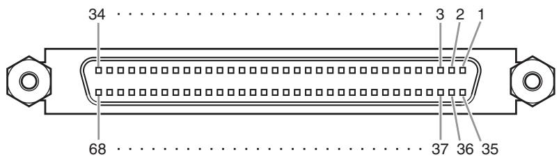
CASCADE IN
| Pin | Signal | Pin | Signal |
| 1 | GND | 35 | GND |
| 2 | Input 1-2(+) | 36 | Input 1-2(-) |
| 3 | Input 3-4(+) | 37 | Input 3-4(-) |
| 4 | Input 5-6(+) | 38 | Input 5-6(-) |
| 5 | Input 7-8(+) | 39 | Input 7-8(-) |
| 6 | Input 9-10(+) | 40 | Input 9-10(-) |
| 7 | Input 11-12(+) | 41 | Input 11-12(-) |
| 8 | Input 13-14(+) | 42 | Input 13-14(-) |
| 9 | Input 15-16(+) | 43 | Input 15-16(-) |
| 10 | DTR In(+) | 44 | DTR In(-) |
| 11 | RTS Out(+) | 45 | RTS Out(-) |
| 12 | GND | 46 | GND |
| 13 | Word Clock In(+) | 47 | Word Clock In(-) |
| 14 | Word Clock Out(+) | 48 | Word Clock Out(-) |
| 15 | Control In(+) | 49 | Control In(-) |
| 16 | Control Out(+) | 50 | Control Out(-) |
| 17 | GND | 51 | ID6 In |
| 18 | GND | 52 | ID6 Out |
| 19 | Input 17-18(+) | 53 | Input 17-18(-) |
| 20 | Input 19-20(+) | 54 | Input 19-20(-) |
| 21 | Input 21-22(+) | 55 | Input 21-22(-) |
| 22 | Input 23-24(+) | 56 | Input 23-24(-) |
| 23 | Input 25-26(+) | 57 | Input 25-26(-) |
| 24 | Input 27-28(+) | 58 | Input 27-28(-) |
| 25 | Input 29-30(+) | 59 | Input 29-30(-) |
| 26 | Input 31-32(+) | 60 | Input 31-32(-) |
| 27 | ID0 In | 61 | ID1 In |
| 28 | ID2 In | 62 | ID3 In |
| 29 | ID4 In | 63 | ID5 In |
| 30 | ID0 Out | 64 | ID1 Out |
| 31 | ID2 Out | 65 | ID3 Out |
| 32 | ID4 Out | 66 | ID5 Out |
| 33 | MSB In | 67 | 2Ch/Line In |
| 34 | FG | 68 | FG |
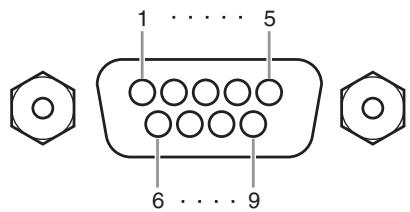
HA REMOTE
| Pin | Signal Name | Pin | Signal Name |
| 1 | GND | 6 | RX+ |
| 2 | RX- | 7 | Reserved |
| 3 | TX- | 8 | Reserved |
| 4 | TX+ | 9 | GND |
| 5 | N.C |
CASCADE OUT
| Pin | Signal | Pin | Signal |
| 1 | GND | 35 | GND |
| 2 | Output 1-2(+) | 36 | Output 1-2(-) |
| 3 | Output 3-4(+) | 37 | Output 3-4(-) |
| 4 | Output 5-6(+) | 38 | Output 5-6(-) |
| 5 | Output 7-8(+) | 39 | Output 7-8(-) |
| 6 | Output 9-10(+) | 40 | Output 9-10(-) |
| 7 | Output 11-12(+) | 41 | Output 11-12(-) |
| 8 | Output 13-14(+) | 42 | Output 13-14(-) |
| 9 | Output 15-16(+) | 43 | Output 15-16(-) |
| 10 | DTR Out(+) | 44 | DTR Out(-) |
| 11 | RTS In(+) | 45 | RTS In(-) |
| 12 | GND | 46 | GND |
| 13 | Word Clock Out(+) | 47 | Word Clock Out(-) |
| 14 | Word Clock In(+) | 48 | Word Clock In(-) |
| 15 | Control Out(+) | 49 | Control Out(-) |
| 16 | Control In(+) | 50 | Control In(-) |
| 17 | GND | 51 | ID6 Out |
| 18 | GND | 52 | ID6 In |
| 19 | Output 17-18(+) | 53 | Output 17-18(-) |
| 20 | Output 19-20(+) | 54 | Output 19-20(-) |
| 21 | Output 21-22(+) | 55 | Output 21-22(-) |
| 22 | Output 23-24(+) | 56 | Output 23-24(-) |
| 23 | Output 25-26(+) | 57 | Output 25-26(-) |
| 24 | Output 27-28(+) | 58 | Output 27-28(-) |
| 25 | Output 29-30(+) | 59 | Output 29-30(-) |
| 26 | Output 31-32(+) | 60 | Output 31-32(-) |
| 27 | ID0 Out | 61 | ID1 Out |
| 28 | ID2 Out | 62 | ID3 Out |
| 29 | ID4 Out | 63 | ID5 Out |
| 30 | ID0 In | 64 | ID1 In |
| 31 | ID2 In | 65 | ID3 In |
| 32 | ID4 In | 66 | ID5 in |
| 33 | MSB Out | 67 | 2Ch/Line Out |
| 34 | FG | 68 | FG |
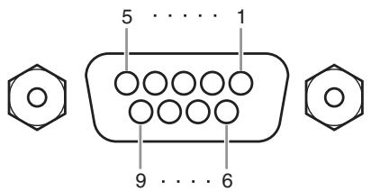
RS422 REMOTE
| Pin | Signal Name | Pin | Signal Name |
| 1 | GND | 6 | GND |
| 2 | RX- | 7 | RX+ |
| 3 | TX+ | 8 | TX- |
| 4 | GND | 9 | GND |
| 5 | N.C |
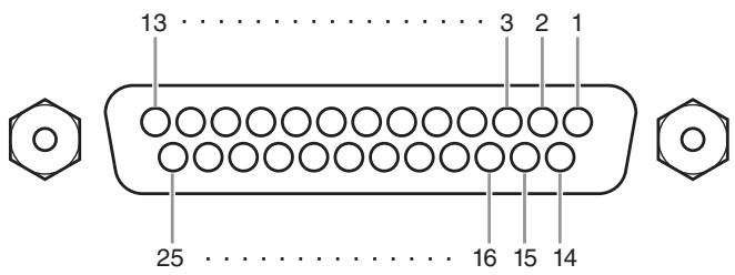
GPI
| Pin | Signal Name | Pin | Signal Name |
| 1 | GPO1 | 14 | GPO2 |
| 2 | GPO3 | 15 | GPO4 |
| 3 | GPO5 | 16 | GPO6 |
| 4 | GPO7 | 17 | GPO8 |
| 5 | GND | 18 | GND |
| 6 | GND | 19 | GND |
| 7 | GND | 20 | GND |
| 8 | GND | 21 | +5V |
| 9 | +5V | 22 | GPI1 |
| 10 | GPI2 | 23 | GPI3 |
| 11 | GPI4 | 24 | GPO9 |
| 12 | GPO10 | 25 | GPO11 |
| 13 | GPO12 | ||
- For information on maximum permissible current, refer to the page 388.
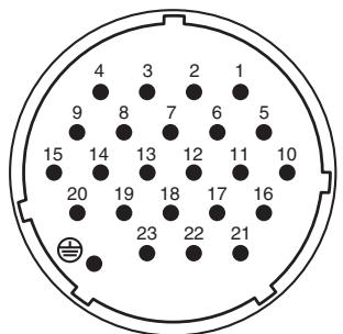
DC POWER INPUT
| Pin | Signal Name | Pin | Signal Name |
| 1 | +24V | 13 | GND |
| 2 | +24V | 14 | GND |
| 3 | +24V | 15 | GND |
| 4 | +24V | 16 | GND |
| 5 | +24V | 17 | GND |
| 6 | +24V | 18 | GND |
| 7 | +24V | 19 | CAUTION(+) |
| 8 | +24V | 20 | CAUTION(-) |
| 9 | +24V | 21 | DETECT A |
| 10 | GND | 22 | DETECT B |
| 11 | GND | 23 | DETECT GND |
| 12 | GND | ⊕ | Frame GND |
Dimensions
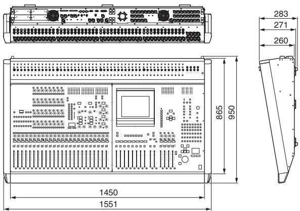
PM5D
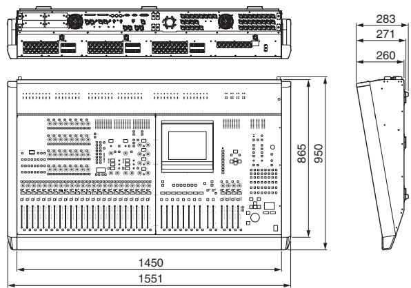
PM5D-RH
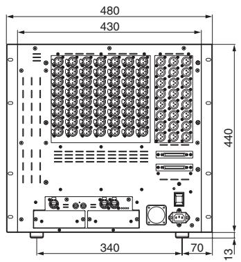
DSP5D
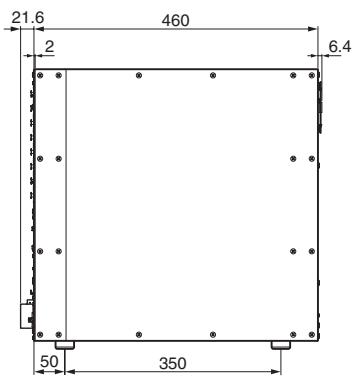
* Specifications and descriptions in this owner's manual are for information purposes only. Yamaha Corp. reserves the right to change or modify products or specifications at any time without prior notice. Since specifications, equipment or options may not be the same in every locale, please check with your Yamaha dealer.
European models
Purchaser/User Information specified in EN55103-1 and EN55103-2.
Inrush Current: 21A (DSP5D only)
Conforms to Environments: E1, E2, E3 and E4
Model: PM5D/PM5D-RH
Version: 1.0
MIDI Implementation Chart
| Function... | Transmitted | Recognized | Remarks | |
| Basic Channel | Default | 1-16 | 1-16 | Memorized |
| Changed | 1-16 | 1-16 | ||
| Mode | Default | X | 1,3 | Memorized |
| Messages | X | X | ||
| Altered | ********** | X | ||
| Note Number | :True Voice | X | 0-127 | |
| ********** | X | |||
| Velocity | Note On | X | O | Effect Control |
| Note Off | X | O | ||
| After Touch | Key's | X | X | |
| Ch's | X | X | ||
| Pitch Bend | X | X | ||
| Control Change | 0,32 | O | O | Bank Select |
| 6,38 | O | O | Data Entry | |
| 98,99 | O | O | NRPN LSB,MSB Assignable Cntrl | |
| 1-31,33-98, 102-119 | O | O | ||
| Prog Change | :True# | O 0-127 | O 0-127 | Assignable |
| ********** | 0-500 | |||
| System Exclusive | O *1 | O *1 | ||
| System Common | :Song Pos | X | X | |
| :Song Sel | X | X | ||
| :Tune | X | X | ||
| System Real Time | :Clock | X | O | Effect Control |
| :Commands | X | X | ||
| Aux Messages | :All Sound Off | X | X | |
| :Reset All Cntrls | X | X | ||
| :Local ON/OFF | X | X | ||
| :All Notes OFF | X | X | ||
| :Active Sense | X | O | ||
| :Reset | X | O | ||
| Notes | *1: Bulk Dump/Request, Parameter Change/Request, and MMC. For MIDI remote and event, all messages can be transmitted. MTC quarter frame message is recognized. | |||
Symbols
0 67
/ATT1 - 48 288
/ ATT STIN/FXRTN 288
Numerics
2TR I/O 237
A
Accessing a screen 27
AD IN section 43
Adjusting the input gain (PM5D-RH) 162
Adjusting the output gain. 162
ADVANCED mode 212, 216
Analog audio connections 33
Analog output connections. 34
Appendices 317
Assign ASSIGN MODE section. 81
Assigning a name 30
Assigning MIDI messages..... 127
GEQ ASSIGN. 173
ATTENUATION 67
AUTO CAPTURE 178
Auto Store function. 91
B
BASIC mode 211, 215
Basic operation. 23
BLANKSKIP 176
Block Diagram ......... End of Manual
Boxes 23
BPM 167
BUSYindicator. 164
Buttons 23, 29
C
Calibrating the GPI IN ports. 135
Calibration. 161
Cascade. 226
BI-DIRECTION 225
Cascade connections 153
CASCADE IN PORT SELECT 224
CASCADE MODE 225
CASCADE OUT PORT SOURCE SELECT.... 225
Source when cascade connected 224
CASCADE FROM 227
CASCADE/Fs. 163
CH 1-12. 293
CH 1-24. 283, 295
CH 1-24 layer. 45
CH 13-24 293
CH 25-36 293
CH 25-48 283, 295
CH 25-48 layer. 45
CH 37-48 293
CH JOB. 274, 314
CH to MIX. 112, 299
CH VIEW 270,311
Channel Library List. 364
CHANNEL SELECT 66
Channel strip. 45, 47, 61
INPUT channel 45
ST IN/FX RTN channel 47
STEREO A/B channel 61
Channel structure. 12
Character palette 23
COMP LIBRARY 71,256,295
COMPLINK ASSIGN....85,261,299
COMPPARAM 253,291
Compressor. 68, 110
Operations 71
Compressor Library List. 319
Compressor Link. 85
Connecting to a computer 158
Connections. 31
Analog audio connections 33
Analog output connections. 34
Digital input/output connections 36
Console Lock 152
Control change parameter assignments 343
Control changes 125
CSV EXPORT mode. 212
CSV IMPORT mode 216
Cue. 99
Cue function 104
CUE mode 102
CUE section 99, 102
Cue/Solo functions. 102
Solo function. 104
CUE FUNCTION 241
CUE/SOLO 240
CUE FUNCTION. 241
INPUT SOLO SAFE 241
OUTPUT SOLO SAFE 242
SOLO ON/OFF 240
Cursor. 23, 27
D
Daisy-chain connections. 38
Data Entry. 24
DCA 81
DCA CUE indicator 164
DCA GROUP ASSIGN. 258, 296
DCA Groups 81, 82
DELAY. 66
Digital input/output connections... 36
Dimensions 395
DIMM indicator. 164
DIRECT OUT PATCH 80,278
DIRECT RECALL 165
DIRECT RECALL ASSIGN. 177
Direct Recall function. 91
Directly outputting. 80
DISPLAY ACCESS 24, 27
DISPLAY ACCESS section. 165
Distribution box. 38
DITHER. 229
Divergence 146
DME CONTROL 199
Drag and drop. 26
DSP5D About the DSP5D. 12
Cascade connections with the PM5D. 13
Difference with the PM5D..... 12
Front panel. 21
Initializing. 160
Rear panel 22
Specifying the machine ID number 153
DSP5D Editor 13
Dynamics Parameters 321
E
Effect Library Program Change Table 337
Effects 111
Basic operations. 114
Editing 115
EFFECT ASSIGN. 168
EFFECT CUE indicator 164
EFFECT functions. 166
EFFECT LIBRARY 169
Effect Library List 324
EFFECT PARAM 112, 113, 115, 166
Effects Parameters 325
Freeze effect. 117
Inserting into a channel. 113
PLUG-IN 170
Recalling. 114
Storing 115
Tap Tempo function 116
Using via a MIX bus 112
Effects and tempo synchronization 336
Electrical characteristics 389
Encoder function. 49
Encoder mode. 165
EQ (Equalizer) 69, 287
Operations 73
EQ Library List 317
EQ Link. 85
EQLINK ASSIGN. 85,260,298
EQPARAM. 250,286
EQ STIN/FXRTN 287
Error Messages 379
EVENTindicator. 164
EVENT LIST. 177
AUTO CAPTURE 178
DISABLE. 163,177
ENABLE 163,177
EVENTRECALL. 178
EVENT TRIGGER. 178
MOVE DOWN 179
MOVE UP. 179
Events 123, 125
Examples of systems 31, 32
Exchanging the fader and encoder functions 49
EXTERNAL CUE indicator 164
External user interface 25

Fade function. 95
FADE TIME. 95, 184
FADER ASSIGN. 217
Fader calibration 161
FADERFLIP/ENCODER MODE section. 48
FADER MODE 165
FADER MODE section. 149
FADER START 196
FADER VIEW 273, 314
Faders 23, 29
FADING indicator 164
Features 10
Firmware versions. 14
FIX ASSIGN VIEW 307
FIXED type MIX bus. 52
FRAME RATE. 179
Freeze effect. 117
Front panel 20
Front panel (DSP5D) 21
Function Name 163
Function parameters 164
FX RTN channels 1-4. 42
FX RTN layer 47,165

Gain. 67
Adjusting 162
Gain reduction 110
Gate 110
Operations 72
GATE LIBRARY. 72, 294
GATE Library List 318
GATE PARAM. 289
GEQ
GEQ ASSIGN 173
GEQ function. 170
GEQLIBRARY. 174
GEQPARAM. 118,170
GEQ module
Expanding. 119
Patching. 118
Global 24,165,166
EFFECT functions. 166
GEQ function. 170
METER function 231
MIDI REMOTE function. 188
MON/CUE function. 234
SCENE function. 175
SYS/W.CLOCK function 219
UTILITY function 204
GLOBAL PASTE 97,187
Global Paste function 97
GPI 194
Calibrating. 135
General Purpose Interface..... 133
GPI IN 133
GPI IN MONITOR 195
GPI indicator. 164
GPI OUT 136, 195
TALLY 137,196
USERDEFINEDKEYS. 137
Graphic EQ. 118
Basic Operations. 119
Group 65
Cue and Solo 103
Grouping 81
ASSIGN MODE section. 81
DCA. 81

HA (Head Amp) 44, 228
HA indicator 164
HALIBRARY. 230,249,285
HORIZONTAL PAIR. 53, 221
HPF (High Pass Filter). 69
Operations 73

I/O card. 36
Indicator 164
Initializing. 160
Initializing (DSP5D). 160
Input. 24, 165, 277
/ATT1 -48 288
/ ATT STIN/FXRTN. 288
/ EQ function 286
CH 1-12 293
CH 1-24 283, 295
CH 13-24 293
CH 25-36 293
CH 25-48 283, 295
CH 37-48 293
CH JOB. 314
CH LIBRARY 316
CH to MIX. 299
CH VIEW 311
COMP LIBRARY 295
COMPLINK ASSIGN 299
COMPPARAM. 291
DCA GROUP ASSIGN 296
DCA/GROUP function. 296
DELAY function. 295
DIRECT OUT PATCH 278
EQ 287
EQ LIBRARY 289
EQLINK ASSIGN 298
EQPARAM. 286
EQ STIN/FXRTN 287
FADER VIEW 314
FIX ASSIGN VIEW. 307
GATE LIBRARY 294
GATEPARAM. 289
GATE/COMP function. 289
HA LIBRARY 285
HA/INSERT function. 283
INSERT. 284
INSERT PATCH 279
INSERT STIN. 284
INSERT/DIRECT OUT POINT 281
LCR. 308
M/S. 311
MIXSENDVIEW 305
MUTE GROUP ASSIGN 297
NAME. 282
PAN/ROUTING function..... 299
PATCH 277
PATCH function 277
PATCH LIBRARY 283
SIGNAL FLOW 313
STIN 293,295
STIN/FXRTN 283
SURRPARAM 309
SURR VIEW. 310
VIEW function. 311
Input a character 30
Assigning a name. 30
INPUT CH layer. 165
Input channel
12,41,283,293,295
AD IN section. 43
Channel strip. 45, 47
FADERFLIP/ENCODERMODE
section 48
FX RTN channels 1-4. 42
Input channels 1-48 41
ST IN channels 1-4. 41
INPUT CUE indicator. 164
INPUT DCA/GROUP function... 296
COMPLINK ASSIGN 299
DCA GROUP ASSIGN 296
EQLINK ASSIGN 298
MUTE GROUP ASSIGN 297
INPUT DELAY function 295
Input Gain Reduction. 233
INPUT GATE/COMP function ... 289
COMP LIBRARY 295
COMPPARAM. 291
GATE LIBRARY 294
GATEPARAM. 289
Input channel 293
STIN 293
CH 1-24 283
CH 25-48 283
HA LIBRARY 285
Input channel 283
INSERT 284
STIN/FXRTN 283
INPUT GR 110,233
INPUT HA/INSERT function..... 283
INPUT METER. 231
INPUT /EQ function 286
/ATT1 - 48 288
/ ATT STIN/FXRTN. 288
EQ. 287
EQPARAM 286
EQ STIN/FXRTN. 287
INPUT EQ LIBRARY 289
Input patch 74
INPUT PATCH function 277
DIRECT OUT PATCH. 278
INPUT PACH LIBRARY..... 283
INSERT PATCH 279
INSERT/DIRECT OUT POINT 281
NAME 282
INPUT SOLO SAFE 241
INPUT VIEW function 311
CH JOB. 314
CH VIEW 311
FADER VIEW 314
INPUT CH LIBRARY. 316
SIGNAL FLOW 313
Input/output characteristics 384
INSERT 284
INSERT IN MIX 1-24. 248
INSERT PATCH. 78,244,279
INSERT POINT 246
INSERT STIN 284
INSERT/DIRECT OUT POINT 78,80,113,281
Inserting
External device. 77
Internal effect into a channel .. 113
Insert-out and insert-in
Patching. 78
Internal memory
Initializing. 160
K
KEY IN CUE indicator 164
Keyboard 25
Knobs 23, 29
L
LATCH. 193
Layer. 45, 47
[CH 1-24]/[CH 25-48] keys.... 45
[ST IN 1-4]/[FX RTN 1-4] keys 47
INPUT CH. 165
ST IN/FX RTN. 165
LCR 267,308
LCR [B] indicator. 164
LCR indicator 164
LEARN 193
Level Diagram.....End of Manual
LFE. 146
Library
COMP LIBRARY 295
EFFECT LIBRARY 169
GATE LIBRARY. 294
GEQLIBRARY. 174
HA LIBRARY. 249, 285
INPUT CH LIBRARY. 316
INPUT EQ LIBRARY 289
INPUT PATCH LIBRARY..... 283
OUTPUT CH LIBRARY. 275
OUTPUT PATCH LIBRARY.. 247
Linking 81
ASSIGN MODE section. 81
Compressor Link. 85
EQ Link. 85
LOAD 215
ADVANCED mode 216
BASIC mode 215
CSV IMPORT mode 216
Loading. 140
M
M/S. 311
Major new functionality in PM5D V2.0 14
Manual organize. 15
MATRIX channels 1-8. 56
MATRIX section 63
MATRIX/ST function. 262
LCR 267
MATRIX/ST ROUTING 262
MIX to MATRIX VIEW 264
SURR SETUP. 268
MATRIX/STEREO. 251, 255, 257
Memory cards. 138
METER function. 231
INPUT GR 233
INPUT METER 231
OUTPUT GR 234
OUTPUT METER 232
Meter section 108, 164
Meters. 108
Metering point 109
MIDI. 123
Assigning MIDI messages..... 127
MIDI events 132
MIDI remote channels. 131
MIDI CTRL CHANGE. 125, 191
MIDI Data Format 368
MIDI EVENT. 175
MIDI Implementation Chart..... 396
MIDI indicator. 164
MIDI PGM CHANGE. 123, 190
MIDI REMOTE 127, 192
MIDI REMOTE function 188
DME CONTROL 199
FADER START 196
GPI 194
LATCH. 193
LEARN 193
MMC. 197, 198
RS422. 197, 198
TALLY 196
TRANSPORT. 198
MIDI SETUP 188
mini-YGDAI I/O cards. 36
MIX 1-24 251, 255, 257
MIX channel output signals. 60
MIX channels 1-24. 55
MIX section 57, 164
MIXSENDVIEW 305
MIX to MATRIX VIEW 264
MIXER SETUP 53,221
PAIR MODE 221
MMC. 197, 198
MON/CUE function. 234
2TR I/O 237
CUE/SOLO 240
MONITOR 238
OSCILLATOR. 236
TALKBACK 234
Monitor 99,101,238
CUE mode 102
SOLO mode 102
MONITOR sections 99
Mouse. 25
MOVE DOWN 179
MOVE UP. 179
MUTE GROUP ASSIGN..... 259, 297
Mute Groups. 81, 83
MUTE MASTER 165
N
NAME. 247, 282
NEXT SCENE/NEXT EVENT .... 163
NOISE GATE 67
NRPN parameter assignments..... 360
0
OFFSET TIME 179
Operating section 10
Option card. 37
types of I/O card. 36
OSCindicator. 164
OSCILLATOR. 105, 107, 236
Output 24,165,243
CH JOB. 274
CH LIBRARY 275
CH VIEW. 270
COMP function. 253
COMP LIBRARY. 256
COMPLINK ASSIGN 261
COMPPARAM. 253
DCA GROUP ASSIGN 258
DCA/GROUP function. 258
DELAY function. 257
EQ function. 250
EQ LIBRARY. 252
EQLINKASSIGN 260
EQPARAM. 250
FADER VIEW 273
HA LIBRARY 249
INSERT function. 248
INSERT IN MATRIX/STREO/MONITOR..... 248
INSERT IN MIX 1-24. 248
INSERT PATCH 244
INSERT POINT 246
LCR. 267
MATRIX/ST function. 262
MATRIX/ST ROUTING. 262
MATRIX/STEREO 251,255,257
MIX 1-24. 251, 255, 257
MIX to MATRIX VIEW 264
MUTE GROUP ASSIGN 259
NAME. 247
PATCH. 243
PATCH function. 243
PATCH LIBRARY 247
SIGNAL FLOW 272
SURR SETUP 268
VIEW function. 270
Output channel. 12, 55
Channel strip. 61
MATRIX channels 1-8 56
MATRIX section 63
MIX channels 1-24. 55
MIX section. 57
STEREO A/B channels. 55
OUTPUT COMP function 253
COMP LIBRARY 256
COMPPARAM. 253
MATRIX/STEREO 255
MIX 1-24 255
OUTPUT CUE indicator. 164
OUTPUT DCA/GROUP function 258
COMPLINKASSIGN. 261
DCA GROUP ASSIGN 258
EQLINK ASSIGN 260
MUTE GROUP ASSIGN. 259
OUTPUT DELAY function 257
OUTPUT EQ function 250
EQPARAM. 250
MATRIX/STEREO 251
MIX 1-24 251
OUTPUT EQ LIBRARY 252
Output Gain Reduction. 234
OUTPUT GR 110,234
OUTPUT INSERT function 248
HA LIBRARY 249
INSERT IN MIX 1-24. 248
OUTPUT METER 232
Output patch. 75
OUTPUT PACH function. 243
INSERT PATCH 244
INSERT POINT 246
NAME 247
OUTPUT PATCH LIBRARY.. 247
OUTPUT PORT ATT 229
Output signals from MATRIX channels 64
OUTPUT SOLO SAFE 242
OUTPUT VIEW function. 270
CH JOB. 274
CH VIEW 270
FADER VIEW 273
OUTPUT CH LIBRARY 275
SIGNAL FLOW 272
Overview of the PM5D system..... 10
P
PAIR MODE. 53, 221
Pairing
Enabling/disabling. 53
Pairing MIX channels 59
PAN/ROUTING function 299
CH to MIX. 299
FIX ASSIGN VIEW 307
LCR 308
M/S. 311
MIXSENDVIEW 305
SURRPARAM 309
SURR VIEW. 310
Panels. 16
Parameter Lock 152
Parameters that can be assigned to control changes. 341
Parametric EQ
Basic Operations. 121
PASTE MODE 97
Patch. 74
Patching
Insert-out and insert-in 78
Pattern 146
Phantom power. 44
Phase. 67
Pin Assignment 394
PM5D Editor. 13
PM5D, PM5D-RH model. 11
Pointer 23
PREFERENCE 1/2. 204
PRESENT TIME. 163
PREVIEW indicator 90
PREVIEW mode 90
Program changes 123
R
Rear panel 18
Rear panel (DSP5D) 22
RECALLSAFE. 94,182
Recall Safe function 94
Reference section. 163
Remote control 123
Control changes 125
MIDI. 123
MIDI Remote 127
MIDI remote channels. 131
Program changes. 123
Restoring to the default state. 40
RS422. 197, 198
RS422 indicator. 164
s
SAVE 138,211
ADVANCED mode 212
BASIC mode 211
CSV EXPORT mode. 212
Scene. 87, 175
Restoring to the default state.... 40
Scene memory 87, 163
Auto Store function 91
Basic operation. 89
BLANKSKIP. 176
DIRECT RECALL ASSIGN.... 177
Direct Recall function. 91
EVENT LIST 177
Fade function 95
FADE TIME 184
GLOBAL PASTE 187
Global Paste function 97
GPI OUT CONTROL. 176
MIDI EVENT 175
PREVIEW mode. 90
Program Change Table 337
RECALLSAFE. 182
Recall Safe function 94
Recalling. 90
REMOTE TRANSPORT. 176
SCENE 175
SCENE FUNCTION 176
SCENE function 175
SCENE MEMORY section...... 88
SELECTIVE RECALL 180
Selective Recall function. 92
Storing 89
TRACKING RECALL 186
Tracking Recall function. 96
Scroll 28
Scroll bar. 24
SECURITY 218
Security functions. 151
Console Lock. 152
Parameter Lock 152
Selected channel 65, 164
Editing parameters. 70
SELECTED CHANNEL section 65
Selecting the word clock master..... 38
SELECTIVE RECALL 92,180
Selective Recall function 92
Sending signals
from the MATRIX section to output jacks 63
from the STEREO A/B channels to MATRIX buses. 62
from the STEREO A/B channels to output jacks .... 62
to a MIX bus. 51
to MATRIXbuses 58
to the STEREO bus. 50, 59
Setup 31
Word clock. 38
Shown in the display. 163
SIGNAL FLOW 272,313
Signals sent to a VARI type MIX bus. 60
to MATRIXbuses 64
Solo function. 104
SOLO indicator. 164
SOLO mode 102
SOLO ON/OFF 240
Specifications. 381
Specifying the machine ID number 153
STIN 293,295
ST IN channels 1-4. 41
STIN layer 47,165
START OFFSET button. 185
START TIME 179
STEREO. 68
STEREO A/B channels. 55
STEREO B. 222
STIN/FXRTN 283
Surround
SURRPARAM 309
SURR SETUP 268
SURR VIEW 310
Surround mode. 142, 143, 222
Surround pan. 142, 222
Divergence 146
LFE. 146
Notes 147
Pattern 146
Surround buses 143
Synchronization. 15
SYS/W.CLOCK function. 219
CASCADE 226
DITHER 229
HA (Head Amp) 228
HA LIBRARY. 230
MIXER SETUP 221
OUTPUT PORT ATT 229
WORD CLOCK 219
T
Tabs. 23, 164
TALKBACK. 105, 106, 234
TALKBACK/OSCILLATOR sections 105
TALLY. 196
TAP TEMPO BPM 167
Tap Tempo function 116
Tapping 26
TB indicator. 164
TIME CODE. 163, 179
TIME CODE SETUP. 179
Top panel. 16
TRACKING indicator 164
TRACKING RECALL. 96, 186
Tracking Recall function. 96
TRANSPORT. 198
Troubleshooting. 380
U
USB
USB TO HOST connector..... 158
USE AS CENTER BUS 222, 239
USE AS STEREO BUS. 222, 239
USERDEFINE 208
USER DEFINED KEY BANK 165
USER DEFINED KEYS. 148, 196
USER DEFINED section. 148
User interface. 23
Using an internal effect via a MIX bus 112
UTILITY function. 204
FADER ASSIGN. 217
LOAD 215
PREFERENCE 1/2. 204
SAVE 211
SECURITY 218
USERDEFINE 208
V
VARI type MIX bus. 52
VERTICAL PAIR 53,221
W
Warning Messages 377
Word clock 15,38,219
MEMO
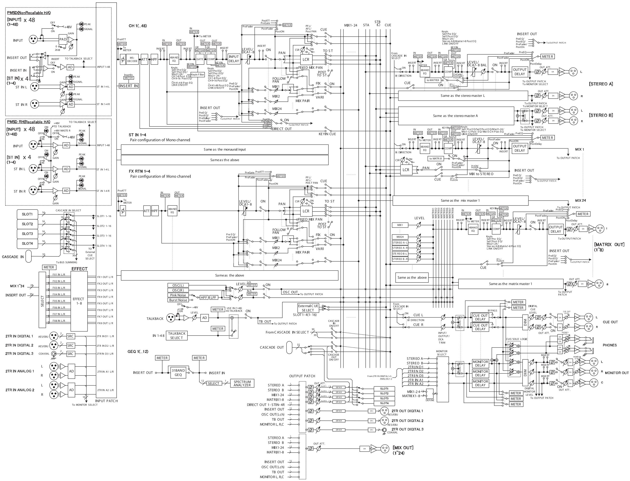
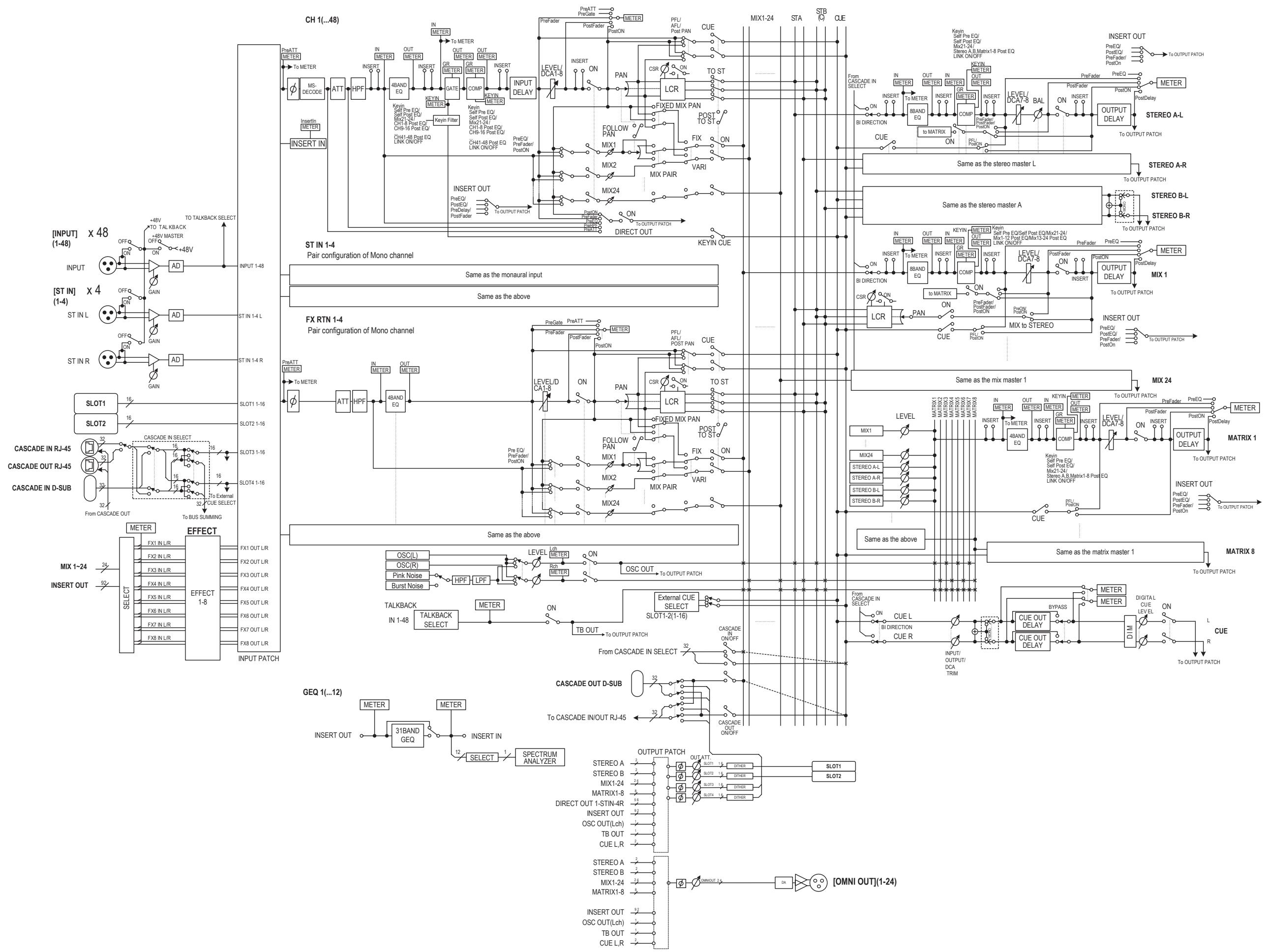
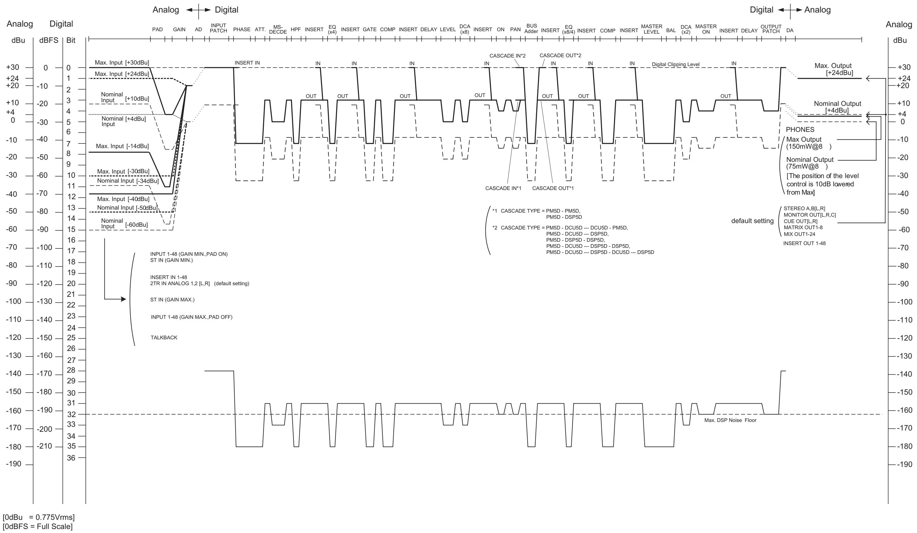
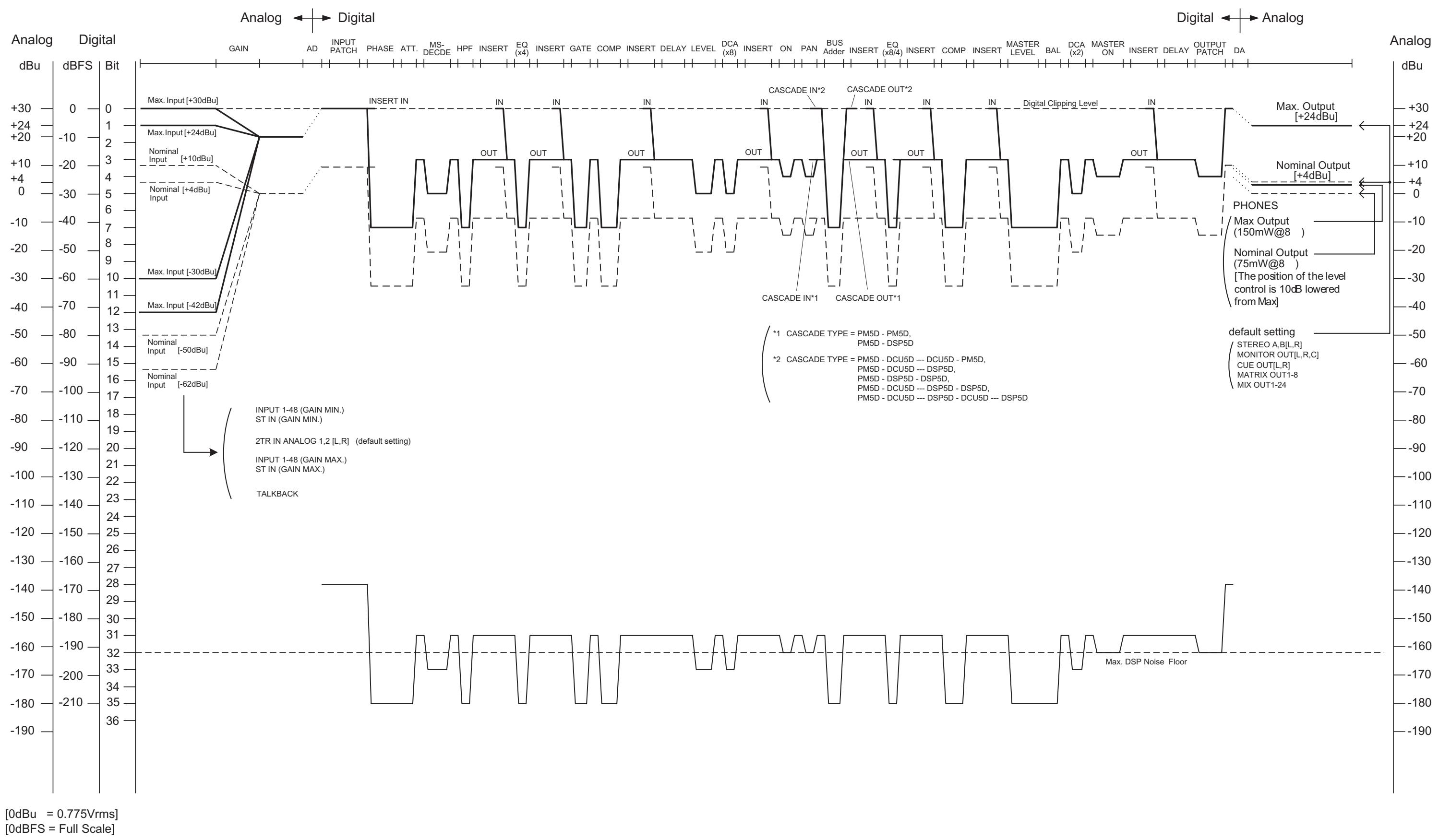
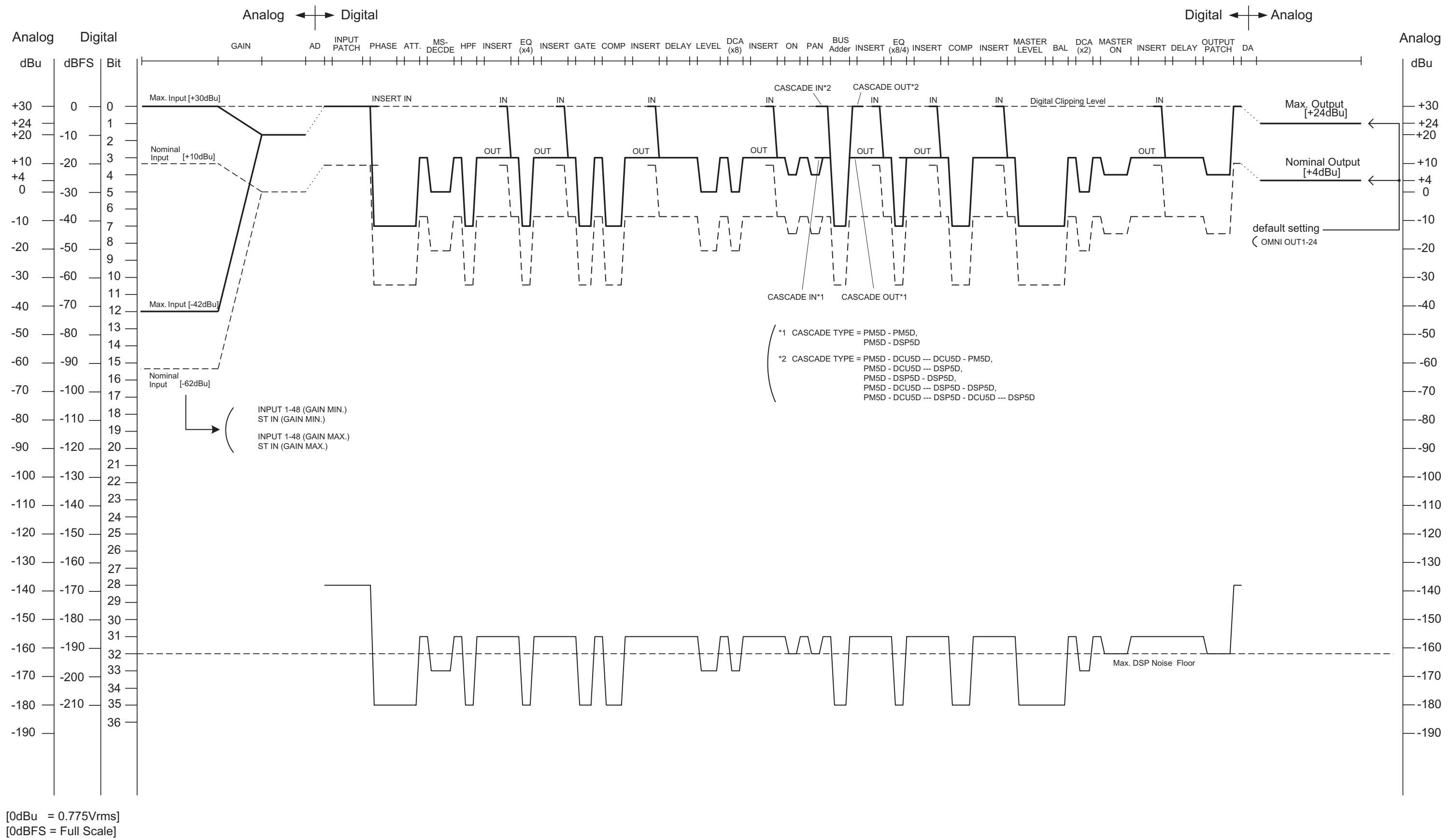
For details of products, please contact your nearest Yamaha representative or the authorized distributor listed below.
Yamaha Canada Music Ltd.
135 Milner Avenue, Scarborough, Ontario,
M1S 3R1, Canada
Tel: 416-298-1311
U.S.A.
Yamaha Corporation of America
6600 Orangethorpe Ave., Buena Park, Calif. 90620,
U.S.A.
Tel: 714-522-9011
CENTRAL & SOUTH AMERICA
MEXICO
Yamaha de Mexico S.A. de C.V.
Calz. Javier Rojo Gomez #1149,
Col. Guadalupe del Moral
C.P.09300, Mexico,D.F.,Mexico
Tel: 55-5804-0600
BRAZIL
PANAMA AND OTHER LATIN
AMERICAN COUNTRIES/
CARIBBEAN COUNTRIES
Yamaha Music Latin America, S.A.
Torre Banco General, Piso 7, Urbanizacion Marbella,
Sherbourne Drive, Tilbrook, Milton Keynes,
MK7 8BL, England
Tel: 01908-366700
GERMANY
Yamaha Music Europe GmbH
Siemensstraße 22-34, 25462 Rellingen, Germany
Tel: 04101-3030
Branch Switzerland in Zurich
Seefeldstrasse 94, 8008 Zurich, Switzerland
Tel: 01-383 3990
AUSTRIA
Yamaha Music Europe GmbH Branch Austria
Schleiergasse 20, A-1100 Wien, Austria
Tel: 01-60203900
CZECH REPUBLIC/SLOVAKIA/
HUNGARY/SLOVENIA
Yamaha Music Europe GmbH Branch Austria
Schleiergasse 20, A-1100 Wien, Austria
Tel: 01-602039025
POLAND
Yamaha Music Europe GmbH
YS Copenhagen Liaison Office
Generatorvej 6A, DK-2730 Herlev, Denmark
Tel: 44 92 49 00
NORWAY
Yamaha Music (Russia)
Office 4015, entrance 2, 21/5 Kuznetskii
Most street, Moscow, 107996, Russia
Tel: 495 626 0660
OTHER EUROPEAN COUNTRIES
Yamaha Music Europe GmbH
Siemensstraße 22-34, 25462 Rellingen, Germany
Tel: +49-4101-3030
AFRICA
Yamaha Corporation,
Asia-Pacific Music Marketing Group
Nakazawa-cho 10-1, Naka-ku, Hamamatsu,
Japan 430-8650
Tel: +81-53-460-2313
MIDDLE EAST
TURKEY/CYPRUS
Yamaha Music Europe GmbH
Siemensstraße 22-34, 25462 Rellingen, Germany
Tel: 04101-3030
OTHER COUNTRIES
Yamaha Music Gulf FZE
LOB 16-513, P.O.Box 17328, Jubel Ali,
Dubai, United Arab Emirates
Tel: +971-4-881-5868
ASIA
THE PEOPLE'S REPUBLIC OF CHINA
Yamaha Music & Electronics (China) Co.,Ltd.
2F, Yunhedasha, 1818 Xinzha-lu, Jingan-qu,
Shanghai, China
Tel: 021-6247-2211
INDIA
Yamaha Music India Pvt. Ltd.
5F Ambience Corporate Tower Ambience Mall Complex
Ambience Island, NH-8, Gurgaon-122001, Haryana, India
Tel: 0124-466-5551
INDONESIA
PT. Yamaha Music Indonesia (Distributor)
PT. Nusantik
Gedung Yamaha Music Center, Jalan Jend. Gatot
SubROTO Kav. 4, Jakarta 12930, Indonesia
Tel: 21-520-2577
KOREA
Yamaha Music Korea Ltd.
8F, 9F, Dongsung Bldg. 158-9 Samsung-Dong,
Kangnam-Gu, Seoul, Korea
Tel: 080-004-0022
MALAYSIA
Yamaha Music Malaysia, Sdn., Bhd.
Lot 8, Jalan Perbandaran, 47301 Kelana Jaya,
Petaling Jaya, Selangor, Malaysia
Tel: 3-78030900
SINGAPORE
Yamaha Music Asia Pte., Ltd.
03-11 A-Z Building
140 Paya Lebor Road, Singapore 409015
Tel: 747-4374
TAIWAN
Yamaha KHS Music Co., Ltd.
3F, #6, Sec.2, Nan Jing E. Rd. Taipei.
Taiwan 104, R.O.C.
Tel: 02-2511-8688
THAILAND
Siam Music Yamaha Co., Ltd.
4, 6, 15 and 16^th floor, Siam Motors Building.
891/1 Rama 1 Road, Wangmai,
Pathumwan, Bangkok 10330, Thailand
Tel: 02-215-2626
OTHER ASIAN COUNTRIES
Yamaha Corporation,
Asia-Pacific Music Marketing Group
Nakazawa-cho 10-1, Naka-ku, Hamamatsu,
Japan 430-8650
Tel: +81-53-460-2317
OCEANIA
AUSTRALIA
Yamaha Music Australia Pty. Ltd.
Level 1, 99 Queensbridge Street, Southbank,
Victoria 3006, Australia
Tel: 3-9693-5111
COUNTRIES AND TRUST
TERRITORIES IN PACIFIC OCEAN
Yamaha Corporation,
Asia-Pacific Music Marketing Group
Nakazawa-cho 10-1, Naka-ku, Hamamatsu,
Japan 430-8650
Tel: +81-53-460-2313

YAMAHA
Yamaha Pro Audio global web site:
http://www.yamahaproaudio.com/
Yamaha Manual Library