
C 9SA3 - Saw HiKOKI - Free user manual and instructions
Find the device manual for free C 9SA3 HiKOKI in PDF.


| Product Type | Circular Saw |
| Brand | HiKOKI |
| Model | C 9SA3 |
| Blade Diameter | 190 mm (7-1/2 in) |
| Arbor Size | 20 mm (13/16 in) |
| Input Power | 1300 W |
| No-Load Speed | 5500 rpm |
| Max Cutting Depth (90°) | 64 mm (2-1/2 in) |
| Max Cutting Depth (45°) | 43 mm (1-11/16 in) |
| Bevel Capacity | 0° to 45° |
| Weight | 4.2 kg (9.3 lbs) |
| Power Supply | AC 220-240 V, 50/60 Hz |
| Blade Guard | Retractable lower guard with lever |
| Base Plate Material | Aluminum die-cast |
| Cutting Angle Adjustment | Tiltable base with scale |
| Depth Adjustment | Quick-release lever with scale |
| Dust Collection | Dust port for vacuum attachment |
| Shutdown Switch | Double-insulated, lock-off switch |
| Cord Length | 2.5 m (8.2 ft) |
| Included Accessories | Blade, rip fence, wrench, hex key |
| Maintenance | Regular cleaning of air vents, lubrication of bearings |
| Safety Features | Blake brake, spindle lock, anti-kickback |
| Repairability | Replacement parts available from HiKOKI service centers |
| General Information | Designed for professional cutting of wood, plastic, and soft metals |
Frequently Asked Questions - C 9SA3 HiKOKI
User questions about C 9SA3 HiKOKI
0 question about this device. Answer the ones you know or ask your own.
Ask a new question about this device
Download the instructions for your Saw in PDF format for free! Find your manual C 9SA3 - HiKOKI and take your electronic device back in hand. On this page are published all the documents necessary for the use of your device. C 9SA3 by HiKOKI.
USER MANUAL C 9SA3 HiKOKI
natural_image
Technical line drawing of a mechanical cutting tool with a circular background (no text or symbols)
Read through carefully and understand these instructions before use.
使用前務請詳加閱讀

2 3
natural_image
Illustration of a hand using a cutting tool to cut a circular component, with no visible text or symbols.
4

5

natural_image
Technical line drawing of a mechanical assembly with no visible text or symbols6

7A

7B
8

9
10

11A
11B

12
13

14

15

Read all safety warnings, instructions, illustrations and specifications provided with this power tool.
Failure to follow all instructions listed below may result in electric shock, fire and/or serious injury.
Save all warnings and instructions for future reference.
The term "power tool" in the warnings refers to your mains-operated (corded) power tool or battery-operated (cordless) power tool.
1) Work area safety
a) Keep work area clean and well lit.
Cluttered or dark areas invite accidents.
b) Do not operate power tools in explosive atmospheres, such as in the presence of fl ammable liquids, gases or dust.
Power tools create sparks which may ignite the dust or fumes.
c) Keep children and bystanders away while operating a power tool.
Distractions can cause you to lose control.
2) Electrical safety
a) Power tool plugs must match the outlet. Never modify the plug in any way. Do not use any adapter plugs with earthed (grounded) power tools.
Unmodified plugs and matching outlets will reduce risk of electric shock.
b) Avoid body contact with earthed or grounded surfaces, such as pipes, radiators, ranges and refrigerators.
There is an increased risk of electric shock if your body is earthed or grounded.
c) Do not expose power tools to rain or wet conditions.
Water entering a power tool will increase the risk of electric shock.
d) Do not abuse the cord. Never use the cord for carrying, pulling or unplugging the power tool.
Keep cord away from heat, oil, sharp edges or moving parts.
Damaged or entangled cords increase the risk of electric shock.
e) When operating a power tool outdoors, use an extension cord suitable for outdoor use.
Use of a cord suitable for outdoor use reduces the risk of electric shock.
f) If operating a power tool in a damp location is unavoidable, use a residual current device (RCD) protected supply.
Use of an RCD reduces the risk of electric shock.
3) Personal safety
a) Stay alert, watch what you are doing and use common sense when operating a power tool. Do not use a power tool while you are tired or under the influence of drugs, alcohol or medication.
A moment of inattention while operating power tools may result in serious personal injury.
b) Use personal protective equipment. Always wear eye protection.
Protective equipment such as a dust mask, non-skid safety shoes, hard hat or hearing protection used for appropriate conditions will reduce personal injuries.
c) Prevent unintentional starting. Ensure the switch is in the off-position before connecting to power source and/or battery pack, picking up or carrying the tool.
Carrying power tools with your fi nger on the switch or energising power tools that have the switch on invites accidents.
d) Remove any adjusting key or wrench before turning the power tool on.
A wrench or a key left attached to a rotating part of the power tool may result in personal injury.
e) Do not overreach. Keep proper footing and balance at all times.
This enables better control of the power tool in unexpected situations.
f) Dress properly. Do not wear loose clothing or jewellery. Keep your hair and clothing away from moving parts.
Loose clothes, jewellery or long hair can be caught in moving parts.
g) If devices are provided for the connection of dust extraction and collection facilities, ensure these are connected and properly used.
Use of dust collection can reduce dust-related hazards.
h) Do not let familiarity gained from frequent use of tools allow you to become complacent and ignore tool safety principles.
A careless action can cause severe injury within a fraction of a second.
4) Power tool use and care
a) Do not force the power tool. Use the correct power tool for your application.
The correct power tool will do the job better and safer at the rate for which it was designed.
b) Do not use the power tool if the switch does not turn it on and off.
Any power tool that cannot be controlled with the switch is dangerous and must be repaired.
c) Disconnect the plug from the power source and/or remove the battery pack, if detachable, from the power tool before making any adjustments, changing accessories, or storing power tools.
Such preventive safety measures reduce the risk of starting the power tool accidentally.
d) Store idle power tools out of the reach of children and do not allow persons unfamiliar with the power tool or these instructions to operate the power tool.
Power tools are dangerous in the hands of untrained users.
e) Maintain power tools and accessories. Check for misalignment or binding of moving parts, breakage of parts and any other condition that may affect the power tool's operation. If damaged, have the power tool repaired before use.
Many accidents are caused by poorly maintained power tools.
f) Keep cutting tools sharp and clean.
Properly maintained cutting tools with sharp cutting edges are less likely to bind and are easier to control.
g) Use the power tool, accessories and tool bits etc. in accordance with these instructions, taking into account the working conditions and the work to be performed.
Use of the power tool for operations different from those intended could result in a hazardous situation.
h) Keep handles and grasping surfaces dry, clean and free from oil and grease.
Slippery handles and grasping surfaces do not allow for safe handling and control of the tool in unexpected situations.
5) Service
a) Have your power tool serviced by a qualified repair person using only identical replacement parts.
This will ensure that the safety of the power tool is maintained.
PRECAUTION
Keep children and infi rm persons away.
When not in use, tools should be stored out of reach of children and infi rm persons.
SAFETY INSTRUCTIONS FOR ALL SAWS
Cutting procedures
a) ⚠️ DANGER: Keep hands away from cutting area and the blade. Keep your second hand on auxiliary handle, or motor housing.
If both hands are holding the saw, they cannot be cut by the blade.
b) Do not reach underneath the workpiece.
The guard cannot protect you from the blade below the workpiece.
c) Adjust the cutting depth to the thickness of the workpiece.
Less than a full tooth of the blade teeth should be visible below the workpiece.
d) Never hold the workpiece in your hands or across your leg while cutting. Secure the workpiece to a stable platform.
It is important to support the work properly to minimize body exposure, blade binding, or loss of control.
e) Hold the power tool by insulated gripping surfaces, when performing an operation where the cutting tool may contact hidden wiring or its own cord.
Contact with a "live" wire will also make exposed metal parts of the power tool "live" and could give the operator an electric shock.
f) When ripping, always use a rip fence or straight edge guide.
This improves the accuracy of cut and reduces the chance of blade binding.
g) Always use blades with correct size and shape (diamond versus round) of arbour holes.
Blades that do not match the mounting hardware of the saw will run off -centre, causing loss of control.
h) Never use damaged or incorrect blade washers or bolt.
The blade washers and bolt were specially designed for your saw, for optimum performance and safety of operation.
Kickback causes and related warnings
- kickback is a sudden reaction to a pinched, jammed or misaligned saw blade, causing an uncontrolled saw to lift up and out of the workpiece toward the operator;
- when the blade is pinched or jammed tightly by the kerf closing down, the blade stalls and the motor reaction drives the unit rapidly back toward the operator;
- if the blade becomes twisted or misaligned in the cut, the teeth at the back edge of the blade can dig into the top surface of the wood causing the blade to climb out of the kerf and jump back toward the operator.
Kickback is the result of saw misuse and/or incorrect operating procedures or conditions and can be avoided by taking proper precautions as given below.
a) Maintain a fi rm grip with both hands on the saw and position your arms to resist kickback forces. Position your body to either side of the blade, but not in line with the blade.
Kickback could cause the saw to jump backwards, but kickback forces can be controlled by the operator, if proper precautions are taken.
b) When blade is binding, or when interrupting a cut for any reason, release the trigger and hold the saw motionless in the material until the blade comes to a complete stop.
Never attempt to remove the saw from the work or pull the saw backward while the blade is in motion or kickback may occur.
Investigate and take corrective actions to eliminate the cause of blade binding.
c) When restarting a saw in the workpiece, centre the saw blade in the kerf so that the saw teeth are not engaged into the material.
If a saw blade binds, it may walk up or kickback from the workpiece as the saw is restarted.
d) Support large panels to minimise the risk of blade pinching and kickback.
Large panels tend to sag under their own weight. Supports must be placed under the panel on both sides, near the line of cut and near the edge of the panel.
e) Do not use dull or damaged blades.
Unsharpened or improperly set blades produce narrow kerf causing excessive friction, blade binding and kickback.
f) Blade depth and bevel adjusting locking levers must be tight and secure before making the cut.
If blade adjustment shifts while cutting, it may cause binding and kickback.
g) Use extra caution when sawing into existing walls or other blind areas.
The protruding blade may cut objects that can cause kickback.
Lower guard function
a) Check the lower guard for proper closing before each use. Do not operate the saw if the lower guard does not move freely and close instantly. Never clamp or tie the lower guard into the open position.
If the saw is accidentally dropped, the lower guard may be bent. Raise the lower guard with the retracting handle and make sure it moves freely and does not touch the blade or any other part, in all angles and depths of cut.
b) Check the operation of the lower guard spring. If the guard and the spring are not operating properly, they must be serviced before use.
Lower guard may operate sluggishly due to damaged parts, gummy deposits, or a build-up of debris.
c) The lower guard may be retracted manually only for special cuts such as "plunge cuts" and "compound cuts". Raise the lower guard by the retracting handle and as soon as the blade enters the material, the lower guard must be released.
For all other sawing, the lower guard should operate automatically.
d) Always observe that the lower guard is covering the blade before placing the saw down on bench or floor.
An unprotected, coasting blade will cause the saw to walk backwards, cutting whatever is in its path. Be aware of the time it takes for the blade to stop after switch is released.
PRECAUTIONS ON USING CIRCULAR SAW
- Use only blade diameter specified on the machine.
- Do not use any abrasive wheel.
- Do not use saw blades which are deformed or cracked.
- Do not use saw blades made of high speed steel.
- Do not use saw blades which do not comply with the characteristics specified in these instructions.
- Do not stop the saw blades by lateral pressure on the disc.
- Always keep the saw blades sharp.
-
Ensure that the lower guard smoothly and freely.
-
Never use the circular saw with its lower guard fixed in the open position.
- Ensure that the retraction mechanism of the guard system operates correctly.
- Never operate the circular saw with the saw blade turned upward or to the side.
- Ensure that the material is free of foreign matters such as nails.
- For model C9SA3, the saw blades should be 235 mm.
- Disconnect the plug from the receptacle before carrying out any adjustment, servicing or maintenance.
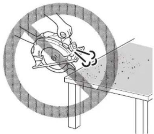
- Do not use the tool with only the blower function. (Fig. 2)
SPECIFICATIONS
| Model C9SA3 | ||
| Voltage (by areas)* | (110 V, 220 V, 230 V, 240 V) ~ | |
| Cutting Depth | 90° 86 mm | |
| 45° 65 mm | ||
| Power Input* 1670 W (110 V), 2000 W (220 – 240 V) | ||
| No-load speed 5200 /min | ||
| Weight (without cord) 7.0 kg | ||
* Be sure to check the nameplate on product as it is subject to change by areas.
STANDARD ACCESSORIES
(1) Saw Blade (Dia. 235 mm) ....1
(2) Hex. bar wrench ....1
(3) Guide 1
(4) Wing-bolt ....1
(5) Lock spring 1
(6) Lever (short type) 1
(7) Dust collector ....1
(8) Side handle 1
(9) Screw (M6 × 20)....2
Standard accessories are subject to change without notice.
APPLICATION
Cutting various types of wood.
PRIOR TO OPERATION
1. Power source
Ensure that the power source to be utilized conforms to the power requirements specified on the product nameplate.
2. Power switch
Squeeze the trigger switch to start the saw and release the trigger to stop.
Pulling the trigger all the way and pressing the On-Lock button will lock the trigger, allowing continuous operation of the saw.
Pull on the trigger once again to disengage the On-Lock button and release the trigger to stop the saw.
Before the tool is plugged in to the receptacle, ensure that the power switch is in the OFF position. If the plug is connected to a receptacle while the power switch is in the ON position, the power tool will start operating immediately, which could cause a serious accident.
3. Extension cord
When the work area is removed from the power source, use an extension cord of sufficient thickness and rated capacity. The extension cord should be kept as short as practicable.
4. Prepare a wooden workbench (Fig. 3)
Since the saw blade will extend beyond the lower surface of the lumber, place the lumber on a workbench when cutting. If a square block is utilized as a workbench, select level ground to ensure it is properly stabilized. An unstable workbench will result in hazardous operation.
5. When using the side handle (Fig. 4)
Securely attach the side handle to the base with the two screws (M6 × 20) when using the side handle.
CAUTION
To avoid possible accident, always ensure that the portion of lumber remaining after cutting is securely anchored or held in position.
6. Using the cord holder (Fig. 5)
Using the cord holder, the cord can be guided toward the rear of the product, as shown in the figure.
If the cord is interfering during operation, hook it into the cord holder and change its angle.
ADJUSTING THE SAW PRIOR TO USE
1. Adjusting the cutting depth
As shown in Fig. 6, hold the handle with one hand while loosening the knob with the other.
The cutting depth can be adjusted by moving the base to the desired position. In such manner adjust the cutting depth and then securely retighten the knob.
2. Adjusting the angle of inclination
As shown in Fig. 7 (A), Fig. 7 (B) by loosening the wing-nut on the incline gauge and the wing-bolt on the base, the saw blade may be inclined to a maximum angle of 45^ in relation to the base. After having completed the adjustment, reconfirm that the wing-nut and the wing-bolt are firmly tightened.
3. Regulating the guide (Fig. 8)
The cutting position can be regulated by moving the guide to the left or right after loosening its wingbolt. The guide may be mounted on either the right or left side of the tool.
4. Adjusting the guide piece
On the circular saw, it is possible to make fine adjustment of the fi xing position of the guide piece, where the saw blade and the premarked line are to be aligned.
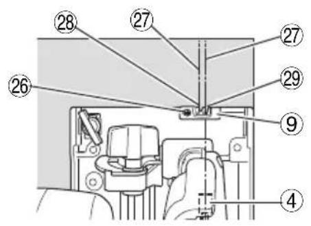
When the saw is shipped from the factory, the linear portion of a front scale on the guide piece is aligned with the central position of the saw blade (Fig. 9).
Loosen the fi xed M4 screw on the guide piece, sl the fi xing position be wrong, and make necessary adjustment of the position.
5. Using the dust collector
To use the vacuum cleaner to gather up saw dust, attach the suction hose to the dust collector which is attached to the main unit by M4 screw. When attaching the dust collector always be sure to change the lever to the short type at this same time (Fig. 10).
CAUTION
Continuing to use the lever that was attached to the main unit prior to shipping from the factory will cause it to bind on the dust collector and will interfere with the lower guard operation.
CUTTING PROCEDURES
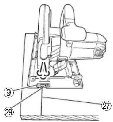
- Place the base on the material, then align the premarked line and the sawblade with the guide piece front scale section at the front of the base (Fig. 9).
When the base is not slanted, use the large cutout as the guide (Fig. 9, Fig. 11 (A)).
If the base is slanted (45 degrees), use the small front scale as the guide (Fig. 9, Fig. 11 (B)).
-
Ensure that the switch is turned to the ON position before the saw blade comes in contact with the lumber. The switch is turned ON when the trigger is squeezed; and OFF when the trigger is released.
-
Moving the saw straight at a constant speed will produce optimum cutting.
CAUTIONS
Prior to cutting operation, make sure the material you are going to cut. If the material to be cut is expected to generate harmful / toxic dusts, make sure the dust bag or appropriate dust extraction system is connected with dust outlet tightly.
Wear the dust mask additionally, if available.
Before starting to saw, ensure that the saw blade has reached full speed revolution.
☐ Should the saw blade stop or make an abnormal noise while operating, promptly turn OFF the switch.
○ Always take care in preventing the power cord from coming near the revolving saw blade.
○ Using the circular saw with the saw blade facing upwards or sideways is very hazardous. Such uncommon applications should be avoided.
○ When cutting materials, always wear protective glasses.
○ When finished with a job, pull out the plug from the receptacle.
MOUNTING AND DISMOUNTING THE SAW BLADE
CAUTION
To avoid serious accident, ensure the switch is in the OFF position, and the power source is disconnected.
1. Dismounting the saw blade
(1) Set the cutting volume at maximum, and place the Circular Saw as shown in Fig. 12.
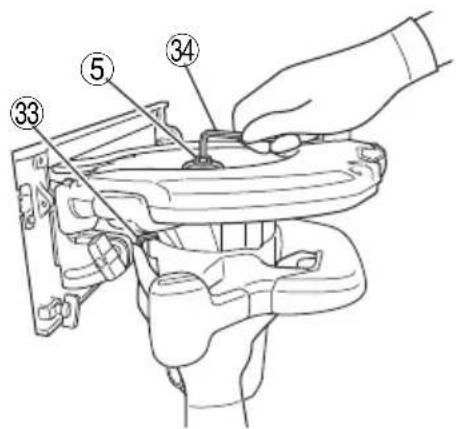
(2) Depress the lock lever, lock the spindle, and remove the hexagonal-socket bolt with the Hex. bar wrench.
(3) While holding the lower guard lever to keep the lower guard fully retracted into the saw cover, remove the saw blade.
2. Mounting the Saw Blade
(1) Thoroughly remove any sawdust which has accumulated on the spindle, bolt and washers.
(2) As shown in Fig. 13, the side of Washer (A) with a projected center the same diameter as the inner diameter of the saw blade and the concave side of Washer (B) must be fitted to the saw blade sides.
To assure proper rotation direction of the saw blade, the arrow direction on the saw blade must coincide with the arrow direction on the saw cover.
(3) To assure proper rotation direction of the saw blade, the arrow direction on the saw blade must coincide with the arrow direction on the saw cover.
(4) Using the fingers, tighten the hexagonal-socket bolt retaining the saw blade as much as possible. Then depress the lock lever, lock the spindle, and thoroughly tighten the bolt.
CAUTION
After having attached the saw blade, reconfirm that the lock lever is firmly secured in the prescribed position.
MAINTENANCE AND INSPECTION
1. Inspecting the saw blade
Since use of a dull saw blade will degrade efficiency and cause possible motor malfunction, sharpen or replace the saw blade as soon as abrasion is noted.
2. Inspecting the mounting screws
Regularly inspect all mounting screws and ensure that they are properly tightened. Should any of the screws be loose, retighten them immediately. Failure to do so could result in serious hazard.
3. Inspecting the carbon brushes (Fig. 14)
The motor employs carbon brushes which are consumable parts. Since an excessively worn carbon brush can result in motor trouble, replace the carbon brushes with new ones having the same carbon brush No. shown in the figure when it becomes worn to or near the "wear limit". In addition, always keep carbon brushes clean and ensue that they slide freely within the brush holders.
CAUTION
When replacing the new carbon brushes, always use genuine HiKOKI carbon brushes with the number specified in the drawing.
4. Replacing carbon brushes
Disassemble the brush caps with a slotted-head screwdriver. The carbon brushes can then be easily removed.
5. Motor unit maintenance
The motor winding is an important part of this tool. Avoid damaging and be careful to avoid contact with cleaning oil or water.
After 50 hours of use, clean the motor by blowing into the ventilation holes of the motor housing with dry air from an air gun or other tool (Fig. 16).
Dust or particle accumulation in the motor can result in damage.
6. Inspecting and maintaining the lower guard
Always make sure that the lower guard moves smoothly. In the event of any malfunction, immediately repair the lower guard.
For cleaning and maintenance, use an air gun or other tool to blow clean the space between the lower guard and gear cover as well as the rotation part of the lower guard with dry air (Fig. 16).
Doing so is effective for the emission of chips or other particles.
Accumulation of chips or other particles around the lower guard may result in malfunction or damage.
WARNING
To prevent dust inhalation or eye irritation, wear protective safety goggles and a dust mask when using an air gun or other tool to clean the lower guard, ventilation holes or other parts of the product.

Fig. 16
7. Adjusting the base and saw blade to maintain perpendicularity
The angle between the base and the saw blade has been adjusted to 90^ , however should this perpendicularity be lost for some reason, adjust in the following manner:
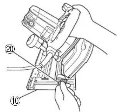
(1) Turn the base face up (Fig. 15) and loosen the wing-nut and wing-bolt (Fig. 7 (A), Fig. 7 (B)).
(2) Apply a square to the base and the saw blade and turning the slotted set screw with a slotted-head screwdriver, shift the position of the base to produce the desired right angle.
8. Service parts list
A: Item No.
B: Code No.
C: No. Used
D: Remarks
CAUTION
Repair, modification and inspection of HiKOKI Power Tools must be carried out by a HiKOKI Authorized Service Center.
This Parts List will be helpful if presented with the tool to the HiKOKI Authorized Service Center when requesting repair or other maintenance.
In the operation and maintenance of power tools, the safety regulations and standards prescribed in each country must be observed.
MODIFICATION
HiKOKI Power Tools are constantly being improved and modified to incorporate the latest technological advancements.
Accordingly, some parts (i.e. code numbers and/or design) may be changed without prior notice.
NOTE
Due to HiKOKI's continuing program of research and development, the specifications herein are subject to change without prior notice.
一般安全規則
警告
CÀNH BÁO AN TOÀN MÁY CƯA ĐĨA
(9) Đình vít (M6×20)....2
(ت) Despite scheme-based software, you can get your attention to the software.

natural_image
Line drawing of a quill pen in an inkwell (no text or symbols)Koki Holdings Co., Ltd.
Shinagawa Intercity Tower A, 15-1, Konan 2-chome, Minato-ku, Tokyo, Japan
- 1) Work area safety
- 2) Electrical safety
- 3) Personal safety
- 4) Power tool use and care
- PRECAUTION
- SAFETY INSTRUCTIONS FOR ALL SAWS
- Cutting procedures
- Kickback causes and related warnings
- Lower guard function
- PRECAUTIONS ON USING CIRCULAR SAW
- STANDARD ACCESSORIES
- APPLICATION
- PRIOR TO OPERATION
- Power source
- Power switch
- Extension cord
- Prepare a wooden workbench (Fig. 3)
- When using the side handle (Fig. 4)
- CAUTION
- Using the cord holder (Fig. 5)
- ADJUSTING THE SAW PRIOR TO USE
- Adjusting the cutting depth
- Adjusting the angle of inclination
- Regulating the guide (Fig. 8)
- Adjusting the guide piece
- Using the dust collector
- CAUTIONS
- MOUNTING AND DISMOUNTING THE SAW BLADE
- Dismounting the saw blade
- Mounting the Saw Blade
- MAINTENANCE AND INSPECTION
- Inspecting the saw blade
- Inspecting the mounting screws
- Inspecting the carbon brushes (Fig. 14)
- Replacing carbon brushes
- Motor unit maintenance
- Inspecting and maintaining the lower guard
- WARNING
- Adjusting the base and saw blade to maintain perpendicularity
- Service parts list
- MODIFICATION
- NOTE
- 一般安全規則
- 警告
- CÀNH BÁO AN TOÀN MÁY CƯA ĐĨA
- Koki Holdings Co., Ltd.
Brand : HiKOKI
Model : C 9SA3
Category : Saw