PWS 1900 - Angle grinder BOSCH - Free user manual and instructions
Find the device manual for free PWS 1900 BOSCH in PDF.
User questions about PWS 1900 BOSCH
0 question about this device. Answer the ones you know or ask your own.
Ask a new question about this device
Download the instructions for your Angle grinder in PDF format for free! Find your manual PWS 1900 - BOSCH and take your electronic device back in hand. On this page are published all the documents necessary for the use of your device. PWS 1900 by BOSCH.
USER MANUAL PWS 1900 BOSCH
natural_image
Illustration of a Bosch electric power tool with a circular base and spoke (no text or symbols on the device itself)Robert Bosch GmbH
Power Tools Division
70745 Leinfelden-Echterdingen
Germany
www.bosch-pt.com
1 609 929 S69 (2009.05) O / 371 UNI

1 609 929 S69
PWS
20-230 | 20-230 J | 1900

BOSCH
de Originalbetriebsanleitung
en Original instructions
fr Notice originale
es Manual original
pt Manual original
it Istruzioni originali
nl Oorspronkelijke gebruiksaanwijzi
da Original brugsanvisning
sv Bruksanvisning i original
no Original driftsinstruks
fi Alkuperäiset ohjeet
el Πρωτότυπο οδηγιών χρήσης
tr Orijinal işletme talimatı
pl Instrukcja oryginalna
cs Původní návod k používání
sk Pôvodný návod na použitie
hu Eredeti használati utasítás
ru Оригинальное руководство по эксплуатации
uk Оригінальна інструкція з експлуатації
ro Instructiuni originale
bg Оригинална инструкция
sr Originalno uputstvo za rad
sl Izvirna navodila
hr Originalne upute za rad
et Algupärane kasutusjuhend
Iv Instrukcijas originālvalodā
It Originali instrukcija

Deutsch . . . . . . . . . . . . . . . . . . . . . . . . . . . . . . . . . . . . . . . . . . . . . . . . . . . . . . . . . . . . . . . . . . . . . . . . . . . . . . 6
English ...... Page 20
Français....Page 33
text_image
OBJ_BUCH-976-001.book Page 3 Monday, April 20, 2009 8:21 AM 3 | 1 609 929 S69 | (20.4.09) Bosch Power Tools4 |
5 |
text_image
BOSCH 1 2 3 5 6 7 6 8 9 10 11 SDS-clic 4 SDS-clic 10 11 12 13 14 15 16 17 18 19 BOSCH BOSCH 21 20 SDS-clic 10 11 8 BOSCH BOSCH PWS 20-230 PWS 20-230 J PWS 19001 609 929 S69 | (20.4.09)
Bosch Power Tools
1 609 929 S69 | (20.4.09)
Bosch Power Tools
6 | Deutsch
Sicherheitshinweise
Dr. Egbert Schneider Senior Vice President Engineering
Dr. Eckerhard Strötgen Head of Product Certification

Robert Bosch GmbH, Power Tools Division D-70745 Leinfelden-Echterdingen 30.03.2009
Montage
natural_image
Technical line drawing of a mechanical component with concentric rings and a central shaft (no text or symbols)natural_image
Diagram of a hand operating a mechanical component with a rotating knob and directional arrow (no text or symbols)natural_image
Mechanical component diagram showing a rotating assembly with bolts and a curved arrow indicating rotation (no text or symbols present)natural_image
Illustration of robotic arm positioning on a platform with motion arrows (no text or symbols)natural_image
Diagram of a mechanical device with rotating components and directional arrows indicating motion (no text or symbols)General Power Tool Safety Warnings
WARNING Read all safety warnings and all instructions. Failure to follow
the warnings and instructions may result in electric shock, fire and/or serious injury.
Save all warnings and instructions for future reference.
The term “power tool” in the warnings refers to your mains-operated (corded) power tool or battery-operated (cordless) power tool.
1) Work area safety
a) Keep work area clean and well lit. Cluttered or dark areas invite accidents.
b) Do not operate power tools in explosive atmospheres, such as in the presence of flammable liquids, gases or dust. Power tools create sparks which may ignite the dust or fumes.
c) Keep children and bystanders away while operating a power tool. Distractions can cause you to lose control.
2) Electrical safety
a) Power tool plugs must match the outlet. Never modify the plug in any way. Do not use any adapter plugs with earthed (grounded) power tools. Unmodified plugs and matching outlets will reduce risk of electric shock.
b) Avoid body contact with earthed or grounded surfaces, such as pipes, radiators, ranges and refrigerators. There is an increased risk of electric shock if your body is earthed or grounded.
c) Do not expose power tools to rain or wet conditions. Water entering a power tool will increase the risk of electric shock.
d) Do not abuse the cord. Never use the cord for carrying, pulling or unplugging the power tool. Keep cord away from heat, oil, sharp edges and moving parts. Damaged or entangled cords increase the risk of electric shock.
e) When operating a power tool outdoors, use an extension cord suitable for outdoor use. Use of a cord suitable for outdoor use reduces the risk of electric shock.
f) If operating a power tool in a damp location is unavoidable, use a residual current device (RCD) protected supply. Use of an RCD reduces the risk of electric shock.
3) Personal safety
a) Stay alert, watch what you are doing and use common sense when operating a power tool. Do not use a power tool while you are tired or under the influence of drugs, alcohol or medication. A moment of inattention while operating power tools may result in serious personal injury.
b) Use personal protective equipment. Always wear eye protection. Protective equipment such as dust mask, non-skid safety shoes, hard hat, or hearing protection used for appropriate conditions will reduce personal injuries.
c) Prevent unintentional starting. Ensure the switch is in the off-position before connecting to power source and/or battery pack, picking up or carrying the tool. Carrying power tools with your finger on the switch or energising power tools that have the switch on invites accidents.
d) Remove any adjusting key or wrench before turning the power tool on. A wrench or a key left attached to a rotating part of the power tool may result in personal injury.
e) Do not overreach. Keep proper footing and balance at all times. This enables better control of the power tool in unexpected situations.
f) Dress properly. Do not wear loose clothing or jewellery. Keep your hair, clothing and gloves away from moving parts. Loose clothes, jewellery or long hair can be caught in moving parts.


g) If devices are provided for the connection of dust extraction and collection facilities, ensure these are connected and properly used. Use of dust collection can reduce dust-related hazards.
4) Power tool use and care
a) Do not force the power tool. Use the correct power tool for your application. The correct power tool will do the job better and safer at the rate for which it was designed.
b) Do not use the power tool if the switch does not turn it on and off. Any power tool that cannot be controlled with the switch is dangerous and must be repaired.
c) Disconnect the plug from the power source and/or the battery pack from the power tool before making any adjustments, changing accessories, or storing power tools. Such preventive safety measures reduce the risk of starting the power tool accidentally.
d) Store idle power tools out of the reach of children and do not allow persons unfamiliar with the power tool or these instructions to operate the power tool. Power tools are dangerous in the hands of untrained users.
e) Maintain power tools. Check for misalignment or binding of moving parts, breakage of parts and any other condition that may affect the power tool's operation. If damaged, have the power tool repaired before use. Many accidents are caused by poorly maintained power tools.
f) Keep cutting tools sharp and clean. Properly maintained cutting tools with sharp cutting edges are less likely to bind and are easier to control.
g) Use the power tool, accessories and tool bits etc. in accordance with these instructions, taking into account the working conditions and the work to be performed. Use of the power tool for operations different from those intended could result in a hazardous situation.
5) Service
a) Have your power tool serviced by a qualified repair person using only identical replacement parts. This will ensure that the safety of the power tool is maintained.
Safety Warnings for Angle Grinder
Safety Warnings common for Grinding, Sanding, Wire Brushing or Abrasive Cutting Off Operations
This power tool is intended to function as a grinder, sander, wire brush or cut-off tool. Read all safety warnings, instructions, illustrations and specifications provided with this power tool. Failure to follow all instructions listed below may result in electric shock, fire and/or serious injury.
This power tool is not recommended for polishing. Operations for which the power tool was not designed may create a hazard and cause personal injury.
▶ Do not use accessories which are not specifically designed and recommended by the tool manufacturer. Just because the accessory can be attached to your power tool, it does not assure safe operation.
The rated speed of the accessory must be at least equal to the maximum speed marked on the power tool. Accessories running faster than their rated speed can break and fly apart.
The outside diameter and the thickness of your accessory must be within the capacity rating of your power tool. Incorrectly sized accessories cannot be adequately guarded or controlled.
The arbor size of wheels, flanges, backing pads or any other accessory must properly fit the spindle of the power tool. Accessories with arbor holes that do not match the mounting hardware of the power tool will run out of balance, vibrate excessively and may cause loss of control.


22 | English
▶ Do not use a damaged accessory. Before each use inspect the accessory such as abrasive wheels for chips and cracks, backing pad for cracks, tear or excess wear, wire brush for loose or cracked wires. If power tool or accessory is dropped, inspect for damage or install an undamaged accessory. After inspecting and installing an accessory, position yourself and bystanders away from the plane of the rotating accessory and run the power tool at maximum no-load speed for one minute. Damaged accessories will normally break apart during this test time.
▶ Wear personal protective equipment. Depending on application, use face shield, safety goggles or safety glasses. As appropriate, wear dust mask, hearing protectors, gloves and workshop apron capable of stopping small abrasive or workpiece fragments. The eye protection must be capable of stopping flying debris generated by various operations. The dust mask or respirator must be capable of filtrating particles generated by your operation. Prolonged exposure to high intensity noise may cause hearing loss.
▶ Keep bystanders a safe distance away from work area. Anyone entering the work area must wear personal protective equipment. Fragments of workpiece or of a broken accessory may fly away and cause injury beyond immediate area of operation.
Hold power tool by insulated gripping surfaces only, when performing an operation where the cutting accessory may contact hidden wiring or its own cord. Cutting accessory contacting a “live” wire may make exposed metal parts of the power tool “live” and shock the operator.
▶ Position the cord clear of the spinning accessory. If you lose control of the power tool, the cord may be cut or snagged and your hand or arm may be pulled into the spinning accessory.
▶ Never lay the power tool down until the accessory has come to a complete stop. The spinning accessory may grab the surface and pull the power tool out of your control.
▶ Do not run the power tool while carrying it at your side. Accidental contact with the spinning accessory could snag your clothing, pulling the accessory into your body.
▶ Regularly clean the power tool's air vents. The motor's fan will draw the dust inside the housing and excessive accumulation of powdered metal may cause electrical hazards.
▶ Do not operate the power tool near flammable materials. Sparks could ignite these materials.
▶ Do not use accessories that require liquid coolants. Using water or other liquid coolants may result in electrocution or shock.
Kickback and related warnings
- Kickback is a sudden reaction to a pinched or snagged rotating wheel, backing pad, brush or any other accessory. Pinching or snagging causes rapid stalling of the rotating accessory which in turn causes the uncontrolled power tool to be forced in the direction opposite of the accessory's rotation at the point of the binding. For example, if an abrasive wheel is snagged or pinched by the workpiece, the edge of the wheel that is entering into the pinch point can dig into the surface of the material causing the wheel to climb out or kick out. The wheel may either jump toward or away from the operator, depending on direction of the wheel's movement at the point of pinching. Abrasive wheels may also break under these conditions. Kickback is the result of power tool misuse and/or incorrect operating procedures or conditions and can be avoided by taking proper precautions as given below.
- Maintain a firm grip on the power tool and position your body and arm to allow you to resist kickback forces. Always use auxiliary handle, if provided, for maximum control over kickback or torque reaction during start-up. The operator can control torque reactions or kickback forces, if proper precautions are taken.


▶ Never place your hand near the rotating accessory. Accessory may kickback over your hand.
- Do not position your body in the area where power tool will move if kickback occurs.
Kickback will propel the tool in direction opposite to the wheel's movement at the point of snagging.
▶ Use special care when working corners, sharp edges, etc. Avoid bouncing and snagging the accessory. Corners, sharp edges or bouncing have a tendency to snag the rotating accessory and cause loss of control or kickback.
▶ Do not attach a saw chain woodcarving blade or toothed saw blade. Such blades create frequent kickback and loss of control over the power tool.
Additional safety instructions for grinding and cutting off operations
▶ Use only wheel types that are recommended for your power tool and the specific guard designed for the selected wheel.
Wheels for which the power tool was not designed cannot be adequately guarded and are unsafe.
The guard must be securely attached to the power tool and positioned for maximum safety, so the least amount of wheel is exposed towards the operator. The guard helps to protect operator from broken wheel fragments and accidental contact with wheel.
▶ Wheels must be used only for recommended applications. For example: do not grind with the side of the cut-off wheel. Abrasive cut-off wheels are intended for peripheral grinding; side forces applied to these wheels may cause them to shatter.
▶ Always use undamaged wheel flanges that are of correct size and shape for your selected wheel. Proper wheel flanges support the wheel thus reducing the possibility of wheel breakage. Flanges for cut-off wheels may be different from grinding wheel flanges.
▶ Do not use worn down wheels from larger power tools. Wheels intended for larger power tools are not suitable for the higher speed of a smaller tool and may burst.
Additional safety warnings specific for abrasive cutting off operations
Do not “jam” the cut-off wheel or apply excessive pressure. Do not attempt to make an excessive depth of cut. Overstressing the wheel increases the loading and susceptibility to twisting or binding of the wheel in the cut and the possibility of kickback or wheel breakage.
▶ Do not position your body in line with and behind the rotating wheel. When the wheel, at the point of operation, is moving away from your body, the possible kickback may propel the spinning wheel and the power tool directly at you.
When wheel is binding or when interrupting a cut for any reason, switch off the power tool and hold the power tool motionless until the wheel comes to a complete stop. Never attempt to remove the cut-off wheel from the cut while the wheel is in motion otherwise kickback may occur. Investigate and take corrective action to eliminate the cause of wheel binding.
▶ Do not restart the cutting operation in the workpiece. Let the wheel reach full speed and carefully reenter the cut. The wheel may bind, walk up or kickback if the power tool is restarted in the workpiece.
▶ Support panels or any oversized workpiece to minimize the risk of wheel pinching and kickback. Large workpieces tend to sag under their own weight. Supports must be placed under the workpiece near the line of cut and near the edge of the workpiece on both sides of the wheel.
▶ Use extra caution when making a “pocket cut” into existing walls or other blind areas. The protruding wheel may cut gas or water pipes, electrical wiring or objects that can cause kickback.


24 | English
Safety warnings specific for sanding operations
▶ Do not use excessively oversized sanding disc paper. Follow manufacturers recommendations, when selecting sanding paper. Larger sanding paper extending beyond the sanding pad presents a laceration hazard and may cause snagging, tearing of the disc, or kickback.
Safety warnings specific for wire brushing operations
▶ Be aware that wire bristles are thrown by the brush even during ordinary operation. Do not overstress the wires by applying excessive load to the brush. The wire bristles can easily penetrate light clothing and/or skin.
If the use of a guard is recommended for wire brushing, do not allow any interference of the wire wheel or brush with the guard. Wire wheel or brush may expand in diameter due to work load and centrifugal forces.
Additional safety warnings

Wear safety goggles.
▶ Use suitable detectors to determine if utility lines are hidden in the work area or call the local utility company for assistance.
Contact with electric lines can lead to fire and electric shock. Damaging a gas line can lead to explosion. Penetrating a water line causes property damage or may cause an electric shock.
▶ Release the On/Off switch and set it to the off position when the power supply is interrupted, e.g., in case of a power failure or when the mains plug is pulled. This prevents uncontrolled restarting.
▶ When working stone, use dust extraction. The vacuum cleaner must be approved for the extraction of stone dust. Using this equipment reduces dust-related hazards.
▶ Use a cutting guide when cutting stone.
Without sideward guidance, the cutting disc can jam and cause kickback.
▶ When working with the machine, always hold it firmly with both hands and provide for a secure stance. The power tool is guided more secure with both hands.
- Secure the workpiece. A workpiece clamped with clamping devices or in a vice is held more secure than by hand.
- Keep your workplace clean. Blends of materials are particularly dangerous. Dust from light alloys can burn or explode.
▶ Never use the machine with a damaged cable. Do not touch the damaged cable and pull the mains plug when the cable is damaged while working. Damaged cables increase the risk of an electric shock.
Products sold in GB only: Your product is fitted with an BS 1363/A approved electric plug with internal fuse (ASTA approved to BS 1362).
If the plug is not suitable for your socket outlets, it should be cut off and an appropriate plug fitted in its place by an authorised customer service agent. The replacement plug should have the same fuse rating as the original plug.
The severed plug must be disposed of to avoid a possible shock hazard and should never be inserted into a mains socket elsewhere.
Products sold in AUS and NZ only: Use a residual current device (RCD) with a rated residual current of 30 mA or less.
Functional Description

Read all safety warnings and all instructions. Failure to follow the warnings and instructions may result in electric shock, fire and/or serious injury.
While reading the operating instructions, unfold the graphics page for the machine and leave it open.


Intended Use
The machine is intended for cutting, roughing, and brushing metal and stone materials without using water.
For cutting metal, a special protection guard for cutting (accessory) must be used.
For cutting stone, a special extraction hood for cutting with cutting guide (accessory) must be used.
With approved sanding tools, the machine can be used for sanding with sanding discs.
Product Features
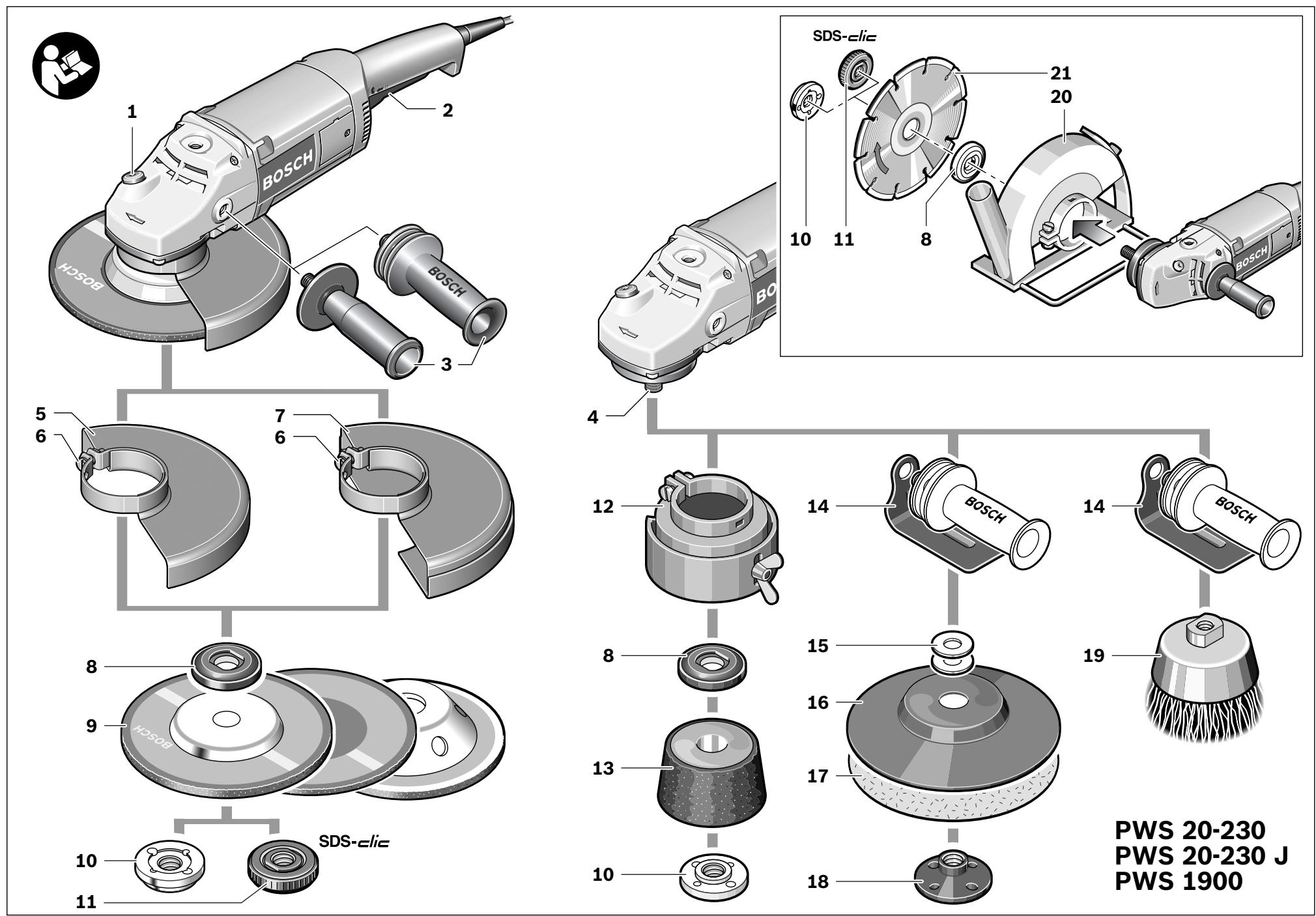
The numbering of the product features refers to the illustration of the machine on the graphics page.
1 Spindle lock button
2 On/Off switch
3 Auxiliary handle
4 Grinder spindle
5 Protection guard for grinding
6 Locking screw for protection guard
7 Protection guard for cutting*
8 Mounting flange with O-ring
9 Grinding/cutting disc*
10 Clamping nut
11 Quick-clamping nut SDS-clic *
12 Protection guard for für grinding cup*
13 Grinding cup*
14 Hand guard*
15 Spacer discs*
16 Rubber sanding plate*
17 Sanding sheet*
18 Round nut*
19 Cup brush*
20 Cutting guide with dust extraction protection guard *
21 Diamond cutting disc*
*Accessories shown or described are not part of the standard delivery scope of the product. A complete overview of accessories can be found in our accessories program.
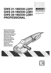
Technical Data
| Angle Grinder | PWS 20-230 | PWS 20-230 J | PWS 1900 | |
| Article number | 3 603 C59 W.. | 3 603 C59 V.. | 3 603 C59 W.. | |
| Rated power input | W | 2000 | 2000 | 1900 |
| Output power | W | 1250 | 1250 | 1170 |
| Rated speed | min^-1 | 6500 | 6500 | 6500 |
| Grinding disc diameter, max. | mm | 230 | 230 | 230 |
| Thread of grinder spindle | M 14 | M 14 | M 14 | |
| Thread length (max.) of grinder spindle | mm | 25 | 25 | 25 |
| Reduced starting current | - | ● | - | |
| Weight according to EPTA-Procedure 01/2003 | kg | 4.4 | 4.4 | 4.4 |
| Protection class | ☐/II | ☐/II | ☐/II |
The values given are valid for nominal voltages [U] of 230/240 V. For lower voltage and models for specific countries, these values can vary.
Please observe the article number on the type plate of your machine. The trade names of the individual machines may vary.
Only for power tools without reduced starting current: Starting cycles generate brief voltage drops. Interference with other equipment/machines may occur in case of unfavourable mains system conditions. Malfunctions are not to be expected for system impedances below 0.25 ohm.
26 | English
Noise/Vibration Information
Measured values determined according to EN 60745.
Typically the A-weighted noise levels of the product are: Sound pressure level 92 dB(A); Sound power level 103 dB(A). Uncertainty K=3 dB.
Wear hearing protection!
Vibration total values (triax vector sum) determined according to EN 60745:
Surface grinding: Vibration emission value a_h=8 m/s^2 , Uncertainty K=1.5 m/s^2 ,
Disk sanding: Vibration emission value a_h=3.5 m/s^2 , Uncertainty K=1.5 m/s^2 .
The vibration emission level given in this information sheet has been measured in accordance with a standardised test given in EN 60745 and may be used to compare one tool with another. It may be used for a preliminary assessment of exposure.
The declared vibration emission level represents the main applications of the tool. However if the tool is used for different applications, with different accessories or poorly maintained, the vibration emission may differ. This may significantly increase the exposure level over the total working period.
An estimation of the level of exposure to vibration should also take into account the times when the tool is switched off or when it is running but not actually doing the job. This may significantly reduce the exposure level over the total working period.
Identify additional safety measures to protect the operator from the effects of vibration such as: maintain the tool and the accessories, keep the hands warm, organisation of work patterns.
Declaration of Conformity CE
We declare under our sole responsibility that the product described under “Technical Data” is in conformity with the following standards or standardization documents: EN 60745 according to the provisions of the directives 2004/108/EC, 98/37/EC (until 28 Dec 2009), 2006/42/EC (from 29 Dec 2009).
Technical file at:
Robert Bosch GmbH, PT/ESC,
D-70745 Leinfelden-Echterdingen
Dr. Egbert Schneider
Senior Vice President
Engineering
Dr. Eckerhard Strötgen
Head of Product
Certification

Robert Bosch GmbH, Power Tools Division
D-70745 Leinfelden-Echterdingen
30.03.2009
Assembly
Mounting the Protective Devices
▶ Before any work on the machine itself, pull the mains plug.
Note: After breakage of the grinding disc during operation or damage to the holding fixtures on the protection guard/power tool, the machine must promptly be sent to an after-sales service agent for maintenance (for addresses, see section „After-sales Service and Customer Assistance“.
Protection Guard for Grinding
Place the protection guard 5 on the spindle collar. Adjust the position of the protection guard 5 to the requirements of the operation and lock the protection guard 5 with the locking screw 6.
▶ Adjust the protection guard 5 in such a manner that sparking is prevented in the direction of the operator.
Protection Guard for Cutting
▶ For cutting metal, always work with the protection guard for cutting 7.
For cutting stone, always work with the cutting guide with dust extraction protection guard 20.
The protection guard for cutting 7 is mounted in the same manner as the protection guard for grinding 5.


Auxiliary Handle
▶ Operate your machine only with the auxiliary handle 3.
Screw the auxiliary handle 3 on the right or left of the machine head depending on the working method.
Vibration-dampening Auxiliary Handle
Vibration Control
The vibration-dampening auxiliary handle reduces the vibrations, making operation more comfortable and secure.
▶ Do not make any alterations to the auxiliary handle.
Do not continue to use an auxiliary handle if it is damaged.
Hand Guard
For operations with the rubber sanding plate 16 or with the cup brush/wheel brush/flap disc, always mount the hand guard 14.
The hand guard 14 is fastened with the auxiliary handle 3.
Mounting the Grinding Tools
▶ Before any work on the machine itself, pull the mains plug.
▶ Grinding and cutting discs become very hot while working; do not touch until they have cooled.
Clean the grinder spindle 4 and all parts to be mounted.
For clamping and loosening the grinding tools, lock the grinder spindle with the spindle lock button 1.
▶ Actuate the spindle lock button only when the grinder spindle is at a standstill. Otherwise, the machine may become damaged.
Grinding/Cutting Disc
Pay attention to the dimensions of the grinding tools. The mounting hole diameter must fit the mounting flange without play. Do not use reducers or adapters.
When using diamond cutting discs, pay attention that the direction-of-rotation arrow on the diamond cutting disc and the direction of rotation of the machine (see direction-of-rotation arrow on the machine head) agree.
See graphics page for the mounting sequence.
To fasten the grinding/cutting disc, screw on the clamping nut 10 and tighten with the two-pin spanner; see Section “Quick-clamping Nut”.
▶ After mounting the grinding tool and before switching on, check that the grinding tool is correctly mounted and that it can turn freely. Make sure that the grinding tool does not graze against the protection guard or other parts.
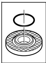
An O-ring (plastic part) is inserted in the mounting flange 8 around the centring collar. If the O-ring is missing or is damaged, it must in all cases be replaced (article number 1 600 210 039) before the mounting flange 8 is mounted.
Flap Disc
▶ For operations with the flap disc, always mount the hand guard 14.
Rubber Sanding Plate
▶ For operations with the rubber sanding plate 16, always mount the hand guard 14.
See graphics page for the mounting sequence. Before mounting the rubber sanding plate 16, put the 2 spacer discs 15 onto the grinder spindle 4.
Screw on the round nut 18 and tighten with the two-pin spanner.
28 | English
Cup Brush/Disc Brush
▶ For operations with the cup brush/wheel brush, always mount the hand guard 14.
See graphics page for the mounting sequence.
The cup brush/disc brush must be able to be screwed onto the grinder spindle until it rests firmly against the grinder spindle flange at the end of the grinder spindle threads. Tighten the cup brush/disc brush with an open-end spanner.
Grinding Cup
▶ When working with the grinding cup, mount the special protection guard 12.
The grinding cup 13 should never project further out of the protection guard 12 than necessary for the respective grinding application. Adjust the protection guard 12 accordingly to this dimension.
See graphics page for the mounting sequence.
Screw on the clamping nut 10 and tighten with the corresponding offset two-pin spanner.
Quick-clamping Nut SDS-clic
For convenient changing of grinding tools without the use of additional tools, you can use the quick-clamping nut 11 instead of the clamping nut 10.
▶ The quick-clamping nut 11 may be used only for grinding or cutting discs.
Use only a flawless, undamaged quick-clamping nut 11.
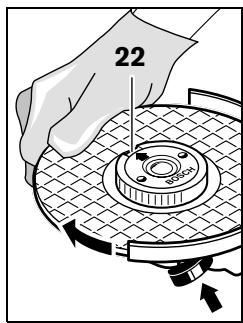
When screwing on, pay attention that the side of the quick-clamping nut 11 with printing does not face the grinding disc; the arrow must point to the index mark 22.
text_image
22Lock the grinder spindle with the spindle lock button 1. To tighten the quick-clamping nut, firmly turn the grinding disc in clockwise direction.
natural_image
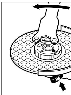
Diagram of a hand pressing down on a mechanical component with a rotating arrow (no text or symbols)A properly attached, undamaged quick-clamping nut can be loosened by hand when turning the knurled ring in anticlockwise direction.
Never loosen a tight quick-clamping nut with pliers. Always use the two-pin spanner. Insert the two-pin
spanner as shown in the illustration.
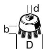
Approved Grinding Tools
All grinding tools mentioned in these operating instructions can be used.
The permissible speed [min^-1] or the circumferential speed [m/s] of the grinding tools used must at least match the values given in the table.
Therefore, observe the permissible rotational/circumferential speed on the label of the grinding tool.

text_image
max. [mm] [mm] D b d [min⁻¹] [m/s]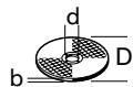


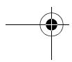

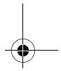
Rotating the Machine Head
▶ Before any work on the machine itself, pull the mains plug.
text_image
H350PThe machine head can be rotated with respect to the machine housing in 90° steps. In this manner, the On/Off switch can be brought into a more convenient position for special
working situations, e. g., for cutting operations using the cutting guide with dust extraction protection guard 20 or for left-handed persons.
Completely unscrew the four screws. Rotate the machine head carefully, without removing it from the housing, to the new position. Screw in and tighten the four screws again.
Dust/Chip Extraction
Dusts from materials such as lead-containing coatings, some wood types, minerals and metal can be harmful to one's health. Touching or breathing-in the dusts can cause allergic reactions and/or lead to respiratory infections of the user or bystanders. Certain dusts, such as oak or beech dust, are considered as carcinogenic, especially in connection with wood-treatment additives (chromate, wood preservative). Materials containing asbestos may only be worked by specialists.
- Use dust extraction whenever possible.
- Provide for good ventilation of the working place.
- It is recommended to wear a P2 filter-class respirator.
Observe the relevant regulations in your country for the materials to be worked.
Operation
Starting Operation
▶ Observe correct mains voltage! The voltage of the power source must agree with the voltage specified on the nameplate of the machine. Power tools marked with 230 V can also be operated with 220 V.
When operating the machine with power from mobile generators that do not have sufficient reserve capacity or are not equipped with suitable voltage control with starting current amplification, loss of performance or untypical behavior can occur upon switching on.
Please observe the suitability of the power generator being used, particularly with regard to the mains voltage and frequency.
Switching On and Off
To start the power tool, press the On/Off switch
2 forward and then down.
To switch off the machine, release the On/Off switch 2.
▶ Check grinding tools before using. The grinding tool must be mounted properly and be able to move freely. Carry out a test run for at least one minute with no load. Do not use damaged, out-of-centre or vibrating grinding tools. Damaged grinding tools can burst and cause injuries.
Reduced starting current (PWS 20-230 J)
The electronic reduced starting current limits the power consumption when switching the tool on and enables operation from a 13 ampere fuse.
Working Advice
▶ Exercise caution when cutting slots in structural walls; see Section “Information on Structures”.
▶ Clamp the workpiece if it does not remain stationary due to its own weight.
▶ Do not strain the machine so heavily that it comes to a standstill.

30 | English
▶ After heavily straining the power tool, continue to run it at no-load for several minutes to cool down the cutting/grinding tool.
- Grinding and cutting discs become very hot while working; do not touch until they have cooled.
▶ Do not use the power tool with a cut-off stand.
Rough Grinding
▶ Never use a cutting disc for roughing.
The best roughing results are achieved when setting the machine at an angle of 30^ to 40^ . Move the machine back and forth with moderate pressure. In this manner, the workpiece will not become too hot, does not discolour and no grooves are formed.
Flap Disc
With the flap disc (accessory), curved surfaces and profiles can be worked.
Flap discs have a considerably higher service life, lower noise levels and lower sanding temperatures than conventional sanding sheets.
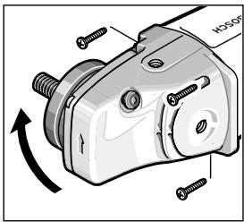
Cutting Metal
▶ For cutting metal, always work with the protection guard for cutting 7.
When cutting, work with moderate feed, adapted to the material being cut. Do not exert pressure onto the cutting disc, tilt or oscillate the machine.
Do not reduce the speed of running down cutting discs by applying sideward pressure.
natural_image
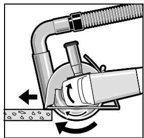
Illustration of a robotic arm performing a circular motion on a surface, with no visible text or symbols.The machine must always work in an up-grinding motion. Otherwise, the danger exists of it being pushed uncontrolled out of the cut.
When cutting profiles and square bar, it is best to start at the smallest cross section.
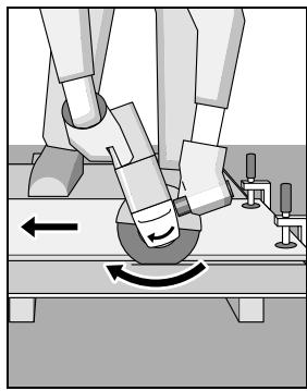
Cutting Stone
For cutting stone, always work with the cutting guide with dust extraction protection guard 20.
▶ The machine may be used only for dry cutting/grinding.
For cutting stone, it is best to use a diamond cutting disc. As a safety measure against jamming, the cutting guide with dust extraction protection guard 20 must be used.
Operate the machine only with dust extraction and additionally wear a dust protection mask.
The vacuum cleaner must be approved for the extraction of masonry dust. Bosch provides suitable vacuum cleaners.
natural_image
Mechanical diagram showing a tool interacting with a pipe and valve, with directional arrows indicating motion (no text or symbols)Switch on the machine and place the front part of the cutting guide on the workpiece. Slide the machine with moderate feed, adapted to the material to be worked.
For cutting especially hard material, e. g., concrete with high pebble content, the diamond cutting disc can overheat and become damaged as a result. This is clearly indicated by circular sparking, rotating with the diamond cutting disc. In this case, interrupt the cutting process and allow the diamond cutting disc to cool by running the machine for a short time at maximum speed with no load.
Noticeable decreasing work progress and circular sparking are indications of a diamond cutting disc that has become dull. Briefly cutting into abrasive material (e.g. lime-sand brick) can re-sharpen the disc again.
Information on Structures
Slots in structural walls are subject to the Standard DIN 1053 Part 1, or country-specific regulations.
These regulations are to be observed under all circumstances. Before beginning work, consult the responsible structural engineer, architect or the construction supervisor.


Maintenance and Service
Maintenance and Cleaning
▶ Before any work on the machine itself, pull the mains plug.
▶ For safe and proper working, always keep the machine and ventilation slots clean.
In extreme working conditions, conductive dust can accumulate in the interior of the machine when working with metal. The protective insulation of the machine can be degraded. The use of a stationary extraction system is recommended in such cases as well as frequently blowing out the ventilation slots and installing a residual current device (RCD).
Please store and handle the accessory(-ies) carefully.
If the machine should fail despite the care taken in manufacturing and testing procedures, repair should be carried out by an after-sales service centre for Bosch power tools.
In all correspondence and spare parts order, please always include the 10-digit article number given on the type plate of the machine.
After-sales Service and Customer Assistance
Our after-sales service responds to your questions concerning maintenance and repair of your product as well as spare parts. Exploded views and information on spare parts can also be found under:
www.bosch-pt.com
Our customer consultants answer your questions concerning best buy, application and adjustment of products and accessories.
Great Britain
Robert Bosch Ltd. (B.S.C.)
P.O. Box 98
Broadwater Park
North Orbital Road
Denham
Uxbridge
UB 9 5HJ
Tel. Service: +44 (0844) 736 0109
Fax: +44 (0844) 736 0146
Australia, New Zealand and Pacific Islands
Robert Bosch Australia Pty. Ltd.
Power Tools
Locked Bag 66
Clayton South VIC 3169
Customer Contact Center
Inside Australia:
Phone: +61 (01300) 307 044
Fax: +61 (01300) 307 045
Inside New Zealand:
Phone: +64 (0800) 543 353
Fax: +64 (0800) 428 570
Outside AU and NZ:
Phone: +61 (03) 9541 5555
www.bosch.com.au
Republic of South Africa
Customer service
Hotline: +27 (011) 6 51 96 00
Gauteng - BSC Service Centre
35 Roper Street, New Centre
Johannesburg
Tel.: +27 (011) 4 93 93 75
Fax: +27 (011) 4 93 01 26
E-Mail: bsctools@icon.co.za
KZN - BSC Service Centre
Unit E, Almar Centre
143 Crompton Street
Pinetown
Tel.: +27 (031) 7 01 21 20
Fax: +27 (031) 7 01 24 46
E-Mail: bsc.dur@za.bosch.com
Western Cape - BSC Service Centre
Democracy Way, Prosperity Park
Milnerton
Tel.: +27 (021) 5 51 25 77
Fax: +27 (021) 5 51 32 23
E-Mail: bsc@zsd.co.za


32 | English
Bosch Headquarters
Midrand, Gauteng
Tel.: +27 (011) 6 51 96 00
Fax: +27 (011) 6 51 98 80
E-Mail: rbsa-hq.pts@za.bosch.com
Disposal
The machine, accessories and packaging should be sorted for environmental-friendly recycling.
Only for EC countries:
Do not dispose of power tools into household waste! According to the European Guideline 2002/96/EC for Waste Electrical and Electronic Equipment and its implementation into national
right, power tools that are no longer usable must be collected separately and disposed of in an environmentally correct manner.
Subject to change without notice.
Dr. Egbert Schneider Dr. Eckerhard Strötgen Senior Vice President Head of Product Engineering Certification

text_image
ppa. A##u# i.v. Mo#y##Robert Bosch GmbH, Power Tools Division D-70745 Leinfelden-Echterdingen 30.03.2009
Montage
natural_image
Diagram of a hand operating a mechanical component with a rotating arrow and directional arrow (no text or symbols)text_image
Technical diagram of a mechanical component with labeled parts and rotation arrownatural_image
Illustration of a robotic arm performing a circular motion on a surface, with no visible text or symbols.natural_image
Diagram of a mechanical device with rotating components and directional arrows indicating motion (no text or symbols)Robert Bosch (France) S.A.S.
Senior Vice President
Engineering
Dr. Eckerhard Strötgen
Head of Product
Certification


Robert Bosch GmbH, Power Tools Division
D-70745 Leinfelden-Echterdingen
30.03.2009
Montaje
natural_image
Technical diagram of a mechanical bearing assembly with concentric rings and a central shaft (no text or labels)natural_image
Diagram of a hand operating a mechanical device with a rotating knob and adjustment knob (no text or symbols)text_image
Technical diagram of a mechanical component with screws and an arrow indicating rotation or assembly directionnatural_image
Illustration of a robotic arm performing a circular motion on a surface, with no visible text or symbols.natural_image
Mechanical diagram showing a pipe clamp and rotating arm mechanism (no text or symbols)Dr. Egbert Schneider Senior Vice President Engineering
Dr. Eckerhard Strötgen Head of Product Certification
ppa. Macaca i.v. Nuoyen
Robert Bosch GmbH, Power Tools Division D-70745 Leinfelden-Echterdingen 30.03.2009
Montagem
natural_image
Technical diagram of a mechanical bearing assembly (no text or symbols)natural_image
Diagram of a hand pressing down on a mechanical component with a rotating arrow (no text or symbols)text_image
Technical diagram of a mechanical component with labeled parts and rotation arrownatural_image
Illustration of a robotic arm performing a circular motion on a surface, with no visible text or symbols.natural_image
Diagram of a mechanical device with rotating arm and pipe connection (no text or symbols)Dr. Egbert Schneider Senior Vice President Engineering
Dr. Eckerhard Strötgen Head of Product Certification


Robert Bosch GmbH, Power Tools Division D-70745 Leinfelden-Echterdingen 30.03.2009
Montaggio
natural_image
Diagram of a hand operating a mechanical device with a rotating knob and adjustment knob (no text or symbols)text_image
Technical diagram of a mechanical component with labeled parts and rotation arrownatural_image
Illustration of a robotic arm performing a circular motion on a surface, with no visible text or symbols.natural_image
Mechanical diagram showing a tool interacting with a pipe and valve (no text or symbols)Senior Vice President
Engineering
Dr. Eckerhard Strötgen
Head of Product
Certification
ppu. Macaca i.v. Nuoyen
Robert Bosch GmbH, Power Tools Division
D-70745 Leinfelden-Echterdingen
30.03.2009
Montage
natural_image
Technical diagram of a mechanical assembly with concentric rings and a central shaft (no text or symbols)Snelspanmoer SDS-clic
natural_image
Diagram of a hand operating a mechanical device with a rotating knob and adjustment knob (no text or symbols)text_image
Technical diagram of a mechanical component with labeled parts and rotation arrownatural_image
Illustration of a robotic arm performing a circular motion on a surface, with no visible text or symbols.natural_image
Diagram of a mechanical device with rotating components and directional arrows indicating motion (no text or symbols)Senior Vice President
Engineering
Dr. Eckerhard Strötgen
Head of Product
Certification


Robert Bosch GmbH, Power Tools Division
D-70745 Leinfelden-Echterdingen
30.03.2009
Montering
natural_image
Diagram of a hand pressing down on a circular mechanical component with a rotating arrow (no text or symbols)text_image
Technical diagram of a mechanical component with labeled parts and rotation arrownatural_image
Illustration of a robotic arm performing a circular motion on a surface, with no visible text or symbols.natural_image
Diagram of a mechanical device with rotating components and directional arrows indicating motion (no text or symbols)Bosch Service Center
Telegrafvej 3
2750 Ballerup
Tel. Service Center: +45 (4489) 8855
Fax: +45 (4489) 87 55
E-Mail: vaerktoej@dk.bosch.com
Bortskaffelse
Dr. Egbert Schneider Senior Vice President Engineering
Dr. Eckerhard Strötgen Head of Product Certification

text_image
ppa. Jauuwa i.v. NoyenRobert Bosch GmbH, Power Tools Division D-70745 Leinfelden-Echterdingen 30.03.2009
Montage
natural_image
Diagram of a hand operating a mechanical device with a rotating knob and adjustment knob (no text or symbols)natural_image
Illustration of robotic arm positioning with curved motion arrows (no text or symbols)natural_image
Diagram of a mechanical device with rotating components and directional arrows indicating motion (no text or symbols)Bosch Service Center
Telegrafvej 3
2750 Ballerup
Danmark
Tel.: +46 (020) 41 44 55
Fax: +46 (011) 18 76 91
Avfallshantering
Dr. Egbert Schneider Senior Vice President Engineering
Dr. Eckerhard Strötgen Head of Product Certification

text_image
ppa. Macaca i.v. MacyauRobert Bosch GmbH, Power Tools Division
D-70745 Leinfelden-Echterdingen
30.03.2009
Montering
natural_image
Mechanical diagram showing a hand operating a rotating wheel with a gear and adjustment knob (no text or symbols)text_image
Technical diagram of a mechanical component with labeled parts and rotation arrowDu kan dreie girho- det i 90°-skritt. Slik kan på-/av-bryteren settes i en bedre håndteringsposi- sjon for spesielle ar- beidssituasjoner, f. eks. for kapping med avsugdekselet med føringssleiden
20 eller for venstrehendte.
natural_image
Illustration of a robotic arm performing a circular motion on a surface, with no visible text or symbols.natural_image
Diagram of a mechanical device with rotating arm and pipe connection (no text or symbols)Senior Vice President
Engineering
Dr. Eckerhard Strötgen
Head of Product
Certification

Robert Bosch GmbH, Power Tools Division
D-70745 Leinfelden-Echterdingen
30.03.2009
Asennus
natural_image
Diagram of a hand pressing down on a circular mechanical component with a rotating arrow (no text or symbols)text_image
Technical diagram of a mechanical component with labeled parts and rotation arrownatural_image
Illustration of a robotic arm performing a circular motion on a surface, with no visible text or symbols.natural_image
Diagram of a mechanical device with rotating components and directional arrows indicating motion (no text or symbols)Dr. Egbert Schneider Senior Vice President Engineering
Dr. Eckerhard Strötgen Head of Product Certification
ppu. Macena i.v. Nuoyen
Robert Bosch GmbH, Power Tools Division D-70745 Leinfelden-Echterdingen 30.03.2009
Συναρμολόγηση
natural_image
Diagram of a hand operating a mechanical device with a rotating knob and directional arrow (no text or symbols)text_image
Technical diagram of a mechanical component with labeled parts and directional arrow indicating rotation or movementnatural_image
Illustration of a robotic arm performing a circular motion on a surface, with no visible text or symbols.natural_image
Diagram of a mechanical device with rotating components and directional arrows indicating motion (no text or symbols)Senior Vice President
Engineering
Dr. Eckerhard Strötgen
Head of Product
Certification

Robert Bosch GmbH, Power Tools Division
D-70745 Leinfelden-Echterdingen
30.03.2009
Montaj
natural_image
Diagram of a hand operating a mechanical device with a rotating knob and directional arrow (no text or symbols)text_image
Technical diagram of a mechanical component with labeled parts and rotation arrownatural_image
Illustration of robotic arm positioning on a workbench with motion arrows (no text or symbols)natural_image
Diagram of a mechanical device with rotating components and directional arrows indicating motion (no text or symbols)Bosch San. ve Tic. A.S.
Ahi Evran Cad. No:1 Kat:22
Polaris Plaza
80670 Maslak/Istanbul
Dr. Egbert Schneider Senior Vice President Engineering
Dr. Eckerhard Strötgen Head of Product Certification

Robert Bosch GmbH, Power Tools Division D-70745 Leinfelden-Echterdingen 30.03.2009
Montaż
natural_image
Diagram of a hand operating a mechanical component with a rotating arrow and directional arrow (no text or symbols)other
| Category | D (mm) | b (mm) | d (min⁻¹) | [m/s] | | :--- | :--- | :--- | :--- | :--- | | d | 230 | 8 | 22,2 | 6500 | | b | 230 | - | - | 6500 | | d | 100 | 30 | M 14 | 8500 | The values are estimated based on the chart's title and data provided in the table. The values are explicitly labeled as [mm] or [min⁻¹].natural_image
Mechanical component diagram showing a rotating assembly with bolts and a curved arrow indicating rotation (no text or symbols present)natural_image
Illustration of a robotic arm performing a circular motion on a surface, with no visible text or symbols.natural_image
Mechanical diagram showing a tool interacting with a pipe and rotating component (no text or symbols)Dr. Egbert Schneider Senior Vice President Engineering
Dr. Eckerhard Strötgen Head of Product Certification


Robert Bosch GmbH, Power Tools Division D-70745 Leinfelden-Echterdingen 30.03.2009
Montáž
natural_image
Diagram of a hand operating a circular mechanical device with a rotating knob and adjustment knob (no text or symbols)text_image
Technical diagram of a mechanical component with labeled parts and rotation arrownatural_image
Illustration of a robotic arm performing a circular motion on a surface, with directional arrows indicating motion (no text or symbols)natural_image
Diagram of a mechanical device with rotating components and directional arrows indicating motion (no text or symbols)Bosch Service Center PT
K Vápence 1621/16
692 01 Mikulov
Tel.: +420 (519) 305 700
Fax: +420 (519) 305 705
E-Mail: servis.naradi@cz.bosch.com
www.bosch.cz
Zpracování odpadů
Dr. Egbert Schneider Senior Vice President Engineering
Dr. Eckerhard Strötgen Head of Product Certification

Robert Bosch GmbH, Power Tools Division D-70745 Leinfelden-Echterdingen 30.03.2009
Montáž
natural_image
Mechanical diagram showing a hand pressing a circular component with a rotating arrow, no text or symbols presenttext_image
Technical diagram of a mechanical component with labeled parts and an arrow indicating rotation or assembly direction.natural_image
Illustration of a robotic arm performing a circular motion on a surface, with no visible text or symbols.natural_image
Mechanical diagram showing a tool interacting with a pipe and rotating component (no text or symbols)Dr. Egbert Schneider Senior Vice President Engineering
Dr. Eckerhard Strötgen
Head of Product
Certification
ppa. Jauca i.v. Nuoyen
Robert Bosch GmbH, Power Tools Division
D-70745 Leinfelden-Echterdingen
30.03.2009
Összeszerelés
natural_image
Diagram of a hand operating a mechanical component with a rotating arrow and directional arrow (no text or symbols)natural_image
Mechanical component diagram showing a rotating assembly with screws and a central hub (no text or symbols)natural_image
Illustration of a robotic arm performing a circular motion on a surface, with no visible text or symbols.natural_image
Diagram of a mechanical device with rotating arm and pipe connection (no text or symbols)Dr. Egbert Schneider Dr. Eckerhard Strötgen Senior Vice President Head of Product Engineering Certification

Robert Bosch GmbH, Power Tools Division D-70745 Leinfelden-Echterdingen 30.03.2009
Сборка
natural_image
Diagram of a hand operating a rotary knob on a circular workpiece (no text or symbols)text_image
Technical diagram of a mechanical component with labeled parts and rotation arrownatural_image
Illustration of a robotic arm performing a circular motion on a platform, with no visible text or symbols.natural_image
Diagram of a mechanical device with rotating components and directional arrows indicating motion (no text or symbols)Dr. Egbert Schneider Senior Vice President Engineering
Dr. Eckerhard Strötgen Head of Product Certification

i.v. Mogen
Robert Bosch GmbH, Power Tools Division D-70745 Leinfelden-Echterdingen 30.03.2009
Монтаж
natural_image
Diagram of a hand operating a mechanical component with a rotating arrow and directional arrow (no text or symbols)natural_image
Mechanical component diagram showing a rotating assembly with screws and a central hub (no text or symbols)natural_image
Illustration of robotic arm positioning on a platform with motion arrows (no text or symbols)natural_image
Diagram of a mechanical device with rotating components and directional arrows indicating motion (no text or symbols)Dr. Egbert Schneider Senior Vice President Engineering
Dr. Eckerhard Strötgen Head of Product Certification
ppu. Macena i.v. Nuoyen
Robert Bosch GmbH, Power Tools Division D-70745 Leinfelden-Echterdingen 30.03.2009
Montare
natural_image
Diagram of a hand pressing down on a circular mechanical component with a rotating knob (no text or symbols)text_image
Technical diagram of a mechanical component with labeled parts and rotation arrownatural_image
Illustration of a robotic arm performing a circular motion on a surface, with no visible text or symbols.natural_image
Diagram of a mechanical device with rotating components and directional arrows indicating motion (no text or symbols)Bosch Service Center
Str. Horia Măcelariu Nr. 30–34,
013937 Bucureşti
Tel. Service scule electrice: +40 (021) 4 05 75 40
Fax: +40 (021) 4 05 75 66
E-Mail: infoBSC@ro.bosch.com
Dr. Egbert Schneider Senior Vice President Engineering
Dr. Eckerhard Strötgen Head of Product Certification
ppa. Moutka
i.v. Nguyen
Robert Bosch GmbH, Power Tools Division D-70745 Leinfelden-Echterdingen 30.03.2009
Монтиране
natural_image
Diagram of a hand pressing down on a mechanical component with a rotating arrow (no text or symbols)text_image
Technical diagram of a mechanical component with labeled parts and rotation arrownatural_image
Illustration of a robotic arm performing a circular motion on a surface, with no visible text or symbols.natural_image
Diagram of a mechanical device with rotating components and directional arrows indicating motion (no text or symbols)Dr. Egbert Schneider Senior Vice President Engineering
Dr. Eckerhard Strötgen Head of Product Certification

text_image
ppu. dawala i.v. nuoyenRobert Bosch GmbH, Power Tools Division D-70745 Leinfelden-Echterdingen 30.03.2009
Montaža
Montaža zaštitnih uredjaja
- Izvucite pre svih radova na električnom alatu mrežni utikač iz utičnice.
natural_image
Technical diagram of a mechanical bearing assembly with concentric rings and a central shaft (no text or labels)U priključnoj prirubnici 8 je ubačen oko centrirnog venca deo od plastike (O-prsten). Ako O-prsten nedostaje ili je oštećen, mora se neizostavno zameniti (broj predmeta 1 600 210 039), pre nego što se montira priključna prirubnica 8.
Lepezasta brusna ploča
natural_image
Diagram of a hand operating a mechanical press or dial on a workpiece, with no visible text or symbols.text_image
Technical diagram of a mechanical component with labeled parts and rotation arrowMožete glavu prenosnika okretati u 90° podeoka. Na taj način se prekidač za uključivanje- isključivanje za posebne radne slučajeve dovodi u povoljniju poziciju
za rukovanje, na primer za radove presecanja sa usisavajućom haubom sa klizajućom vodjicom 20 ili za levoruke.
Odvrnite sasvim 4 zavrtnja. Oprezno iskrenite glavu prenosnika u novu poziciju ne skidajući sa kućišta. Ponovo stegnite 4 zavrtnja.
Usisavanje prašine/piljevine
▶ Prašine od materijala kao što je premaz koji sadrži olovo, neke vrste drveta, minerali i metal mogu biti štetni po zdravlje. Dodir ili udisanje prašine mogu izazvati alergijske reakcije i/ili oboljenja disajnih puteva radnika ili osoba koje se nalaze u blizini. Neke prašine kao od hrasta i bukve važe kao izazivači raka, posebno u vezi sa dodatnim materijama za obradu drveta (hromati, zaštitna sredstva za drvo). Materijal koji sadrži azbest smeju raditi samo stručnjaci.
- Koristite po mogućnosti neki usisivač za prašinu.
- Pobrinite se za dobro provetravanje radnog mesta.
- Preporučuje se, da se nosi zaštitna maska za disanje sa klasom filtera P2.
natural_image
Illustration of a robotic arm performing a curved motion on a surface, with no visible text or symbols.natural_image
Diagram of a mechanical device with rotating arm and pipe connection (no text or symbols)Dr. Egbert Schneider Senior Vice President Engineering
Dr. Eckerhard Strötgen Head of Product Certification

text_image
ppa. dawala i.v. nuoyenRobert Bosch GmbH, Power Tools Division D-70745 Leinfelden-Echterdingen 30.03.2009
Montaža
natural_image
Diagram of a hand operating a mechanical press or dial on a workpiece, with no visible text or symbols.natural_image
Mechanical component diagram showing a rotating assembly with screws and a central shaft (no text or symbols)natural_image
Illustration of a robotic arm performing a circular motion on a surface, with no visible text or symbolsnatural_image
Mechanical diagram showing a pipe connection with rotating components and directional arrows (no text or symbols)Dr. Egbert Schneider Senior Vice President Engineering
Dr. Eckerhard Strötgen Head of Product Certification

text_image
ppa. dawala i.v. nuoyenRobert Bosch GmbH, Power Tools Division D-70745 Leinfelden-Echterdingen 30.03.2009
Montaža
natural_image
Diagram of a hand pressing down on a mechanical component with a rotating arrow (no text or symbols)text_image
Technical diagram of a mechanical component with labeled parts and rotation arrownatural_image
Illustration of robotic arm performing a circular motion on a platform, with no visible text or symbolsnatural_image
Diagram of a mechanical device with rotating arm and pipe connection (no text or symbols)Dr. Egbert Schneider Senior Vice President Engineering
Dr. Eckerhard Strötgen Head of Product Certification

i.v. Nguyen
Robert Bosch GmbH, Power Tools Division D-70745 Leinfelden-Echterdingen 30.03.2009
Montaaž
natural_image
Diagram of a hand operating a mechanical device with a rotating knob and directional arrow (no text or symbols)text_image
Technical diagram of a mechanical component with labeled parts and rotation arrownatural_image
Illustration of a robotic arm performing a circular motion on a surface, with no visible text or symbols.natural_image
Mechanical diagram showing a tool interacting with a curved pipe and rotating arm (no text or symbols)Staatikaalased juhised
Dr. Egbert Schneider Senior Vice President Engineering
Dr. Eckerhard Strötgen Head of Product Certification

Robert Bosch GmbH, Power Tools Division D-70745 Leinfelden-Echterdingen 30.03.2009
Montāža
natural_image
Technical diagram of a mechanical assembly with concentric rings and a central shaft (no text or symbols)natural_image
Diagram of a hand operating a mechanical device with a rotating knob and adjustment knob (no text or symbols)text_image
Technical diagram of a mechanical component with labeled parts and rotation arrownatural_image
Illustration of a robotic arm performing a circular motion on a surface, with directional arrows indicating rotation (no text or symbols)natural_image
Diagram of a mechanical device with rotating components and directional arrows (no text or symbols)Dr. Egbert Schneider Senior Vice President Engineering
Dr. Eckerhard Strötgen Head of Product Certification

Robert Bosch GmbH, Power Tools Division D-70745 Leinfelden-Echterdingen 30.03.2009
Montavimas
natural_image
Diagram of a hand pressing down on a mechanical component with a rotating arrow (no text or symbols)natural_image
Mechanical component diagram showing a rotating assembly with screws and a central shaft (no text or symbols)natural_image
Illustration of robotic arm positioning on a platform with directional arrows indicating movement (no text or symbols)natural_image
Diagram of a mechanical device with rotating components and directional arrows indicating motion (no text or symbols)natural_image
Pure geometric lines and crosshair symbol without any text or labels