
OptiPlex 745c - Desktop computer DELL - Free user manual and instructions
Find the device manual for free OptiPlex 745c DELL in PDF.


| Type | Desktop computer (Mini Tower) |
| Model | OptiPlex 745c |
| Brand | Dell |
| Dimensions (approx.) | 14.2" x 7.1" x 17.4" (H x W x D) |
| Weight (approx.) | 25 lbs (11.3 kg) |
| Processor | Intel Core 2 Duo (various speeds) |
| Memory | Up to 4 GB DDR2 SDRAM (4 DIMM slots) |
| Storage | SATA hard drive, optical drive, optional floppy drive |
| Graphics | Integrated Intel Graphics Media Accelerator 3000 (or optional PCIe x16 card) |
| Audio | Integrated high-definition audio with line-in, line-out, microphone |
| Network | Integrated 10/100/1000 Ethernet |
| USB Ports | 8x USB 2.0 (2 front, 6 back) |
| Other Connectors | 1 serial, 1 parallel, VGA, PS/2 keyboard/mouse |
| Power Supply | Manual voltage selection (115V/230V), typical 305W |
| Diagnostic Features | 4 diagnostic LEDs, beep codes, Dell Diagnostics utility |
| Operating System | Windows XP or Windows Vista (pre-installed) |
| Security | Padlock ring, password jumper, chassis intrusion switch |
| Expansion Slots | 1 PCIe x16, 1 PCIe x1, 2 PCI |
| Drive Bays | 2x 5.25" external, 1x 3.5" external, 1x 3.5" internal |
| Environmental | Operating temperature: 10°C to 35°C |
Frequently Asked Questions - OptiPlex 745c DELL
User questions about OptiPlex 745c DELL
0 question about this device. Answer the ones you know or ask your own.
Ask a new question about this device
Download the instructions for your Desktop computer in PDF format for free! Find your manual OptiPlex 745c - DELL and take your electronic device back in hand. On this page are published all the documents necessary for the use of your device. OptiPlex 745c by DELL.
USER MANUAL OptiPlex 745c DELL
Notes, Notices, and Cautions

NOTE: A NOTE indicates important information that helps you make better use of your computer.

NOTICE: A NOTICE indicates potential damage to hardware or loss of data and tells you how to avoid the problem.

CAUTION: A CAUTION indicates a potential for property damage, personal injury, or death.
If you purchased a Dell ™ n Series computer, any references in this document to Microsoft ® Windows ® operating systems are not applicable.
Information in this document is subject to change without notice.
© 2007 Dell Inc. All rights reserved.
Reproduction in any manner whatsoever without the written permission of Dell Inc. is strictly forbidden.
Trademarks used in this text: Dell, the DELL logo, and OptiPlex are trademarks of Dell Inc.; Intel is registered trademarks of Intel Corporation; Microsoft, Windows, and Vista are registered trademarks of Microsoft Corporation.
Other trademarks and trade names may be used in this document to refer to either the entities claiming the marks and names or their products. Dell Inc. disclaims any proprietary interest in trademarks and trade names other than its own.
Model DCSM
February 2007 P/N NJ423 Rev. A00
Contents
Finding Information 5
System Views 8
Mini Tower Computer — Front View. 8
Mini Tower Computer — Back View.... 10
Mini Tower Computer — Back-Panel Connectors....11
Removing the Computer Cover. 13
Before You Begin.... 13
Mini Tower Computer. 14
Inside Your Computer 16
Mini Tower Computer. 16
Setting Up Your Computer 19
Set Up Your Keyboard and Mouse 20
Set Up Your Monitor 20
Power Connections.... 21
Solving Problems 21
Dell Diagnostics. 21
System Lights 24
Diagnostic Lights 25
Beep Codes 27
Resolving Software and Hardware Incompatibilities 28
Using Microsoft Windows XP System Restore....28
Reinstalling Microsoft Windows XP 30
Microsoft ® Windows Vista TM 32
The support.dell.com user interface may vary depending
on your selections.... 34
Using the Drivers and Utilities CD. 34
Drivers for Your Computer 34
Index 35
Finding Information

NOTE: Some features or media may be optional and may not ship with your computer. Some features or media may not be available in certain countries.

NOTE: Additional information may ship with your computer.
What Are You Looking For? Find It Here
| ·A diagnostic program for my computer |
| ·Drivers for my computer |
| ·My computer documentation |
| ·My device documentation |
| ·Desktop System Software (DSS) |
Drivers and Utilities CD (ResourceCD)
NOTE: The Drivers and Utilities CD may be optional and may not ship with your computer.
Documentation and drivers are already installed on your computer. You can use the CD to reinstall drivers (see "Using the Drivers and Utilities CD" on page 34), run the Dell Diagnostics (see "Dell Diagnostics" on page 21), or access your documentation.

Readme files may be included on your CD to provide last-minute updates about technical changes to your computer or advanced technical reference material for technicians or experienced users.
NOTE: Drivers and documentation updates can be found at support.dell.com.
• How to remove and replace parts
- Specifications
• How to configure system settings
• How to troubleshoot and solve problems
Dell™ OptiPlex™ User's Guide
Microsoft Windows XP Help and Support Center
1 Click Start→ Help and Support→ Dell User and System Guides→ System Guides.
2 Click the User's Guide for your computer.
The User's Guide is also available on the optional Drivers and Utilities CD.
What Are You Looking For? Find It Here
| Warranty informationTerms and Conditions (U.S. only)Safety instructionsRegulatory informationErgonomics informationEnd User License Agreement | DellTM Product Information Guide |
| How to reinstall my operating system | Operating System CDNOTE: The Operating System CD may be optional and may not ship with your computer.The operating system is already installed on your computer. To reinstall your operating system, use the Operating System CD (see "Reinstalling Microsoft Windows XP" on page 30). After you reinstall your operating system, use the optional Drivers and Utilities CD (ResourceCD) to reinstall drivers for the devices that came with your computer. For more information, see"Drivers and Utilities CD (ResourceCD)" on page 5.Your operating system product key label is located on your computer (see "Service Tag and Microsoft® Windows® Product Key" on page 7).NOTE: The color of your Operating System CD varies according to the operating system you ordered. After you reinstall your operating system, use the optional Drivers and Utilities CD (ResourceCD) to reinstall drivers for the devices that came with your computer. For more information, see"Drivers and Utilities CD (ResourceCD)" on page 5.Your operating system product key label is located on your computer (see "Service Tag and Microsoft® Windows® Product Key" on page 7).NOTE: The color of your Operating System CD varies according to the operating system you ordered. |
| How to use Windows XPHow to work with programs and filesHow to personalize my desktop | Windows Help and Support Center1 Click Start→IHelp and Support.2 Type a word or phrase that describes your problem and click the arrow icon.3 Click the topic that describes your problem.4 Follow the instructions on the screen. |
What Are You Looking For? Find It Here
• Service Tag and Express Service Code
- Microsoft Windows Product Key Label
Service Tag and Microsoft ® Windows ® Product Key
These labels are located on your computer.
- Use the Service Tag to identify your computer when you use support.dell.com or contact support.

- Enter the Express Service Code to direct your call when contacting support.
- Solutions — Troubleshooting hints and tips, articles from technicians, online courses, and frequently asked questions
- Community — Online discussion with other Dell customers
- Upgrades — Upgrade information for components, such as the memory, hard drive, and operating system
- Customer Care — Contact information, service call and order status, and warranty and repair information
- Service and support — Service call status, support history, service contract, and online discussions with support
- Reference — Computer documentation, details on my computer configuration, product specifications, and white papers
- Downloads — Certified drivers, patches, and software updates
- Desktop System Software (DSS)—If you reinstall the operating system on your computer, you should also reinstall the DSS utility. DSS automatically detects your computer and operating system and installs the updates appropriate for your configuration, providing critical updates for your operating system and support for Dell™ 3.5-inch USB floppy drives, Intel® processors, optical drives, and USB devices. DSS is necessary for correct operation of your Dell computer.
Dell Support Website — support.dell.com
NOTE: Select your region or business segment to view the appropriate support site.
To download Desktop System Software:
1 Go to support.dell.com, select your region or business segment, then enter your Service Tag.
2 Select Drivers & Downloads, then click Go.
3 Click your operating system, and then search for the keyword Desktop System Software.
NOTE: The support.dell.com user interface may vary depending on your selections.
System Views
Mini Tower Computer — Front View

1 5.25-inch drive bay Can contain an optical drive. Insert a CD or DVD (if supported) into this drive.
2 5.25-inch drive bay Can contain an optical drive. Insert a CD or DVD (if supported) into this drive.
3 3.5-inch drive bay Can contain an optional floppy drive or optional media card reader.
4 USB 2.0 connectors (2) Use the front USB connectors for devices that you connect occasionally, such as joysticks or cameras, or for bootable USB devices (see your online User's Guide for more information on booting to a USB device).
It is recommended that you use the back USB connectors for devices that typically remain connected, such as printers and keyboards.
5 LAN indicator light This light indicates that a LAN (local area network) connection is established.
6 diagnostic lights Use the lights to help you troubleshoot a computer problem based on the diagnostic code. For more information, see "Diagnostic Lights" on page 25.
7 power button Press this button to turn on the computer.

NOTICE: To avoid losing data, do not turn off the computer by pressing the power button. Instead, perform an operating system shutdown. See "Before You Begin" on page 13 for more information.

NOTICE: If your operating system has ACPI enabled, when you press the power button the computer will perform an operating system shutdown.
8 power light
The power light illuminates and blinks or remains solid to indicate different operating modes:
- No light — The computer is turned off.
• Steady green — The computer is in a normal operating state. - Blinking green — The computer is in a power-saving mode.
- Blinking or solid amber — See your online User's Guide.
To exit from a power-saving mode, press the power button or use the keyboard or the mouse if it is configured as a wake device in the Windows Device Manager. For more information about sleep modes and exiting from a power-saving mode, see your online User's Guide.
See "System Lights" on page 24 for a description of light codes that can help you troubleshoot problems with your computer.
9 hard-drive activity light This light flickers when the hard drive is being accessed.
10 headphone connector Use the headphone connector to attach headphones and most kinds of speakers.
11 microphone connector Use the microphone connector to attach a microphone.
Mini Tower Computer — Back View

1 cover-release latch This latch allows you to open the computer cover.
2 padlock ring Insert a padlock to lock the computer cover.
3 voltage selection switch Your computer is equipped with a manual voltage-selection switch.
To help avoid damaging a computer with a manual voltage-selection switch, set the switch for the voltage that most closely matches the AC power available in your location.

NOTICE: The voltage selection switch must be set to the 115-V position even though the AC power available in Japan is 100 V.
Also, ensure that your monitor and attached devices are electrically rated to operate with the AC power available in your location.
4 power connector Insert the power cable.
5 back-panel connectors Plug serial, USB, and other devices into the appropriate connectors (see "Mini Tower Computer — Back-Panel Connectors" on page 11).
6 card slots Access connectors for any installed PCI and PCI Express cards.
Mini Tower Computer — Back-Panel Connectors

| 1 | parallel connector | Connect a parallel device, such as a printer, to the parallel connector. If you have a USB printer, plug it into a USB connector.NOTE: The integrated parallel connector is automatically disabled if the computer detects an installed card containing a parallel connector configured to the same address. For more information, see your online User's Guide. |
| 2 | link integrity light | · Green — A good connection exists between a 10-Mbps network and the computer.· Orange — A good connection exists between a 100-Mbps network and the computer.· Yellow — A good connection exists between a 1-Cbps (or 1000-Mbps) network and the computer.· Off — The computer is not detecting a physical connection to the network. |
| 3 | network adapter connector | To attach your computer to a network or broadband device, connect one end of a network cable to either a network jack or your network or broadband device. Connect the other end of the network cable to the network adapter connector on the back panel of your computer. A click indicates that the network cable has been securely attached.NOTE: Do not plug a telephone cable into the network connector.On computers with a network connector card, use the connector on the card.It is recommended that you use Category 5 wiring and connectors for your network. If you must use Category 3 wiring, force the network speed to 10 Mbps to ensure reliable operation. |
| 4 | network activity light | Flashes a yellow light when the computer is transmitting or receiving network data. A high volume of network traffic may make this light appear to be in a steady "on" state. |
| 5 | line-out connector | Use the green line-out connector to attach most speakers with integrated amplifiers. |
| 6 | line-in/microphone connector | Use the blue and pink line-in/microphone connector to attach a record/playback device such as a cassette player, CD player, or VCR.; or a personal computer microphone for voice or musical input into a sound or telephony program. |
| 7 | USB 2.0 connectors (6) | Use the back USB connectors for devices that typically remain connected, such as printers and keyboards. |
| 8 | video connector | Plug the cable from your VCA-compatible monitor into the blue connector.NOTE: If you purchased an optional graphics card, this connector will be covered by a cap. Connect your monitor to the connector on the graphics card. Do not remove the cap.NOTE: If you are using a graphics card that supports dual monitors, use the y-cable that came with your computer. |
| 9 | serial connector | Connect a serial device, such as a handheld device, to the serial port. The default designations are COM1 for serial connector 1 and COM2 for serial connector 2. For more information, see your online User's Guide. |
Removing the Computer Cover

CAUTION: Before you begin any of the procedures in this section, follow the safety instructions in the Product Information Guide.

CAUTION: To guard against electrical shock, always unplug your computer from the electrical outlet before removing the cover.
Before You Begin

NOTICE: To avoid losing data, save and close any open files and exit any open programs before you turn off your computer.
1 Shut down the operating system:
a Save and close any open files, exit any open programs, click the Start button, and then click Turn Off Computer
b In the 'Turn off computer window, click 'Turn off . The computer turns off after the operating system shutdown process finishes.
2 Ensure that the computer and any attached devices are turned off. If your computer and attached devices did not automatically turn off when you shut down your operating system, turn them off now.
Before Working Inside Your Computer
Use the following safety guidelines to help protect your computer from potential damage and to help ensure your own personal safety.

CAUTION: Before you begin any of the procedures in this section, follow the safety instructions in the Product Information Guide.

CAUTION: Handle components and cards with care. Do not touch the components or contacts on a card. Hold a card by its edges or by its metal mounting bracket. Hold a component such as a processor by its edges, not by its pins.

NOTICE: Only a certified service technician should perform repairs on your computer. Damage due to servicing that is not authorized by Dell is not covered by your warranty.

NOTICE: When you disconnect a cable, pull on its connector or on its strain-relief loop, not on the cable itself. Some cables have a connector with locking tabs; if you are disconnecting this type of cable, press in on the locking tabs before you disconnect the cable. As you pull connectors apart, keep them evenly aligned to avoid bending any connector pins. Also, before you connect a cable, ensure that both connectors are correctly oriented and aligned.
To avoid damaging the computer, perform the following steps before you begin working inside the computer.
1 Turn off your computer.

NOTICE: To disconnect a network cable, first unplug the cable from your computer and then unplug it from the network wall jack.
2 Disconnect any telephone or telecommunication lines from the computer.
3 Disconnect your computer and all attached devices from their electrical outlets, and then press the power button to ground the system board.
4 If applicable, remove the computer stand (for instructions, see the documentation that came with the stand).

CAUTION: To guard against electrical shock, always unplug your computer from the electrical outlet before removing the cover.
5 Remove the computer cover. See "Mini Tower Computer" on page 14.

NOTICE: Before touching anything inside your computer, ground yourself by touching an unpainted metal surface, such as the metal at the back of the computer. While you work, periodically touch an unpainted metal surface to dissipate any static electricity that could harm internal components.
Mini Tower Computer

CAUTION: Before you begin any of the procedures in this section, follow the safety instructions in the Product Information Guide.

CAUTION: To guard against electrical shock, always unplug your computer from the electrical outlet before removing the computer cover.
1 Follow the procedures in "Before You Begin" on page 13.
2 Lay the computer on its side as shown in the illustration.
3 Locate the cover release latch shown in the illustration. Then, slide the release latch back as you lift the cover.
4 Grip the sides of the computer cover and pivot the cover up using the hinge tabs as leverage points.
5 Remove the cover from the hinge tabs and set it aside on a soft nonabrasive surface.

CAUTION: Graphic card heatsinks may become very hot during normal operation. Ensure that a graphic card heatsink has had sufficient time to cool before you touch it.

1 security cable slot
2 cover release latch
3 padlock ring
Inside Your Computer
Mini Tower Computer

1 optical drive
2 floppy drive
3 power supply
4 chassis-intrusion switch
5 system board
6 heat-sink assembly
7 hard drive
System Board Components

1 fan connector (FAN)
2 processor connector (CPU)
3 processor power connector (12VPOWER)
4 memory module connectors (DIMM_1, DIMM_2, DIMM_3, DIMM_4)
5 RTC reset jumper (RTCRST)
6 password jumper (PSWD)
7 SATA drive connectors (SATA0, SATA1, SATA4, SATA5)
8 manufacturing mode jumper (MFC_MODE)
9 front-panel connector (FNT_PANEL)
12 internal USB (INTERNAL_USB)
13 battery socket (BATT)
14 PCI Express x16 connector (SLOT1)
15 PCI Express x1 connector (SLOT4)
16 PCI connector (SLOT2)
17 PCI connector (SLOT3)
18 serial connector (SER2)
19 floppy drive connector (DSKT)
20 system board speaker (BEEP)
10 power connector (POWER) 21 speaker connector (INT_SPKR)
11 intrusion switch connector (INTRUDER)
Jumper Settings

NOTE: Do not populate the MFG_MODE jumper. Active Management technology will not function properly. Only manufacturing uses this jumper.

| Jumper | Setting | Description |
| PSWD | Password features are enabled (default setting). | |
| Password features are disabled. | ||
| RTCRST | The real-time clock has not been reset. | |
| The real-time clock is being reset (jumped temporarily). |

jumpered

unjumpered
Setting Up Your Computer

CAUTION: Before performing any of the procedures in this section, follow the safety instructions in Product Information Guide.

NOTICE: If your computer has an expansion card installed (such as a modem card), connect the appropriate cable to the card, not to the connector on the back panel.

NOTICE: To help allow the computer to maintain proper operating temperature, ensure that you do not place the computer too close to a wall or other storage compartment that might prevent air circulation around the chassis. See your Product Information Guide for more information.

NOTE: Before you install any devices or software that did not ship with your computer, read the documentation that came with the device or software, or contact the vendor to verify that the device or software is compatible with your computer and operating system.
You must complete all the steps to properly set up your computer. See the appropriate figures that follow the instructions.

NOTICE: Do not attempt to operate a PS/2 mouse and a USB mouse simultaneously.
1 Connect the keyboard and mouse.

NOTICE: Do not connect a modem cable to the network adapter connector. Voltage from telephone communications can cause damage to the network adapter
2 Connect the modem or network cable.
Insert the network cable, not the telephone line, into the network connector. If you have an optional modem, connect the telephone line to the modem.
3 Connect the monitor.
Align and gently insert the monitor cable to avoid bending connector pins. Tighten the thumbscrews on the cable connectors.

NOTE: Some monitors have the video connector underneath the back of the screen. See the documentation that came with your monitor for its connector locations.
4 Connect the speakers.
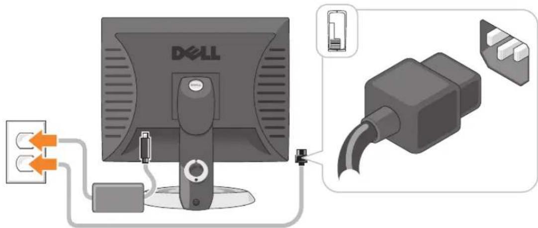
5 Connect power cables to the computer, monitor, and devices and connect the other ends of the power cables to electrical outlets.

NOTICE: To avoid damaging a computer with a manual voltage-selection switch, set the switch for the voltage that most closely matches the AC power available in your location.

NOTICE: In Japan, the voltage selection switch must be set to the 115-V position even though the AC power available in Japan is 100 V.
6 Verify that the voltage selection switch is set correctly for your location.
Your computer has a manual voltage-selection switch. Computers with a voltage selection switch on the back panel must be manually set to operate at the correct operating voltage.
Set Up Your Keyboard and Mouse

Set Up Your Monitor

Power Connections

Solving Problems
Dell provides a number of tools to help you if your computer does not perform as expected. For the latest troubleshooting information available for your computer, see the Dell Support website at support.dell.com.
If computer problems occur that require help from Dell, write a detailed description of the error, beep codes, or diagnostics light patterns, record your Express Service Code and Service Tag below, and then contact Dell from the same location as your computer. For information on contacting Dell, see your online User's Guide.
For an example of the Express Service Code and Service Tag, see "Finding Information" in your computer User's Guide.
Express Service Code: ____
Service Tag:
Dell Diagnostics

CAUTION: Before you begin any of the procedures in this section, follow the safety instructions in the Product Information Guide.
When to Use the Dell Diagnostics
If you experience a problem with your computer, perform the checks in "Solving Problems" in your online User's Guide and run the Dell Diagnostics before you contact Dell for technical assistance. For information on contacting Dell, see your online User's Guide.

NOTICE: The Dell Diagnostics works only on Dell™ computers.
Enter system setup (see "System Setup" in your online User's Guide for instructions), review your computer's configuration information, and ensure that the device you want to test displays in system setup and is active.
Start the Dell Diagnostics from either your hard drive or from the optional Drivers and Utilities CD (ResourceCD).
Starting the Dell Diagnostics From Your Hard Drive
1 Turn on (or restart) your computer.
2 When the DELL logo appears, press
NOTE: If you see a message stating that no diagnostics utility partition has been found, run the Dell Diagnostics from the optional Drivers and Utilities CD (see "Starting the Dell Diagnostics From the Drivers and Utilities CD" on page 22).
If you wait too long and the operating system logo appears, continue to wait until you see the Microsoft® Windows® desktop. Then shut down your computer and try again.
When the boot device list appears, highlight Boot to Utility Partition and press
3 When the Dell Diagnostics Main Menu appears, select the test you want to run.
Starting the Dell Diagnostics From the Drivers and Utilities CD
1 Insert the Drivers and Utilities CD.
2 Shut down and restart the computer.
When the DELL logo appears, press
If you wait too long and the operating system logo appears, continue to wait until you see the Microsoft Windows desktop. Then shut down your computer and try again.
NOTE: The next steps change the boot sequence for one time only. On the next start-up, the computer boots according to the devices specified in system setup.
3 When the boot device list appears, highlight the listing for the CD/DVD drive and press
4 Select the listing for the CD/DVD drive option from the CD boot menu.
5 Select the option to boot from the CD/DVD drive from the menu that appears.
6 Type 1 to start the Drivers and Utilities CD menu.
7 Type 2 to start the Dell Diagnostics.
8 Select Run the 32 Bit Dell Diagnostics from the numbered list. If multiple versions are listed, select the version appropriate for your computer.
9 When the Dell Diagnostics Main Menu appears, select the test you want to run.
Dell Diagnostics Main Menu
1 After the Dell Diagnostics loads and the Main Menu screen appears, click the button for the option you want.
| Option Function | |
| Express Test | Performs a quick test of devices. This test typically takes 10 to 20 minutes and requires no interaction on your part. Run Express Test first to increase the possibility of tracing the problem quickly. |
| Extended Test | Performs a thorough check of devices. This test typically takes an hour or more and requires you to answer questions periodically. |
| Custom Test Tests a specific device. You can customize the tests you want to run. | |
| Symptom Tree Lists the most common symptoms encountered and allows you to select a test based on the symptom of the problem you are having. | |
2 If a problem is encountered during a test, a message appears with an error code and a description of the problem. Write down the error code and problem description and follow the instructions on the screen.
If you cannot resolve the error condition, contact Dell. For information on contacting Dell, see your online User's Guide.

NOTE: The Service Tag for your computer is located at the top of each test screen. If you contact Dell, technical support will ask for your Service Tag.
3 If you run a test from the Custom Test or Symptom Treeoption, click the applicable tab described in the following table for more information.
| Tab Function | |
| Results Displays the results of the test and any error conditions encountered. | |
| Errors | Displays error conditions encountered, error codes, and the problem description. |
| Help Describes the test and may indicate requirements for running the test. | |
| Configuration Displays your hardware configuration for the selected device.The Dell Diagnostics obtains configuration information for all devices from system setup, memory, and various internal tests, and it displays the information in the device list in the left pane of the screen. The device list may not display the names of all the components installed on your computer or all devices attached to your computer. | |
| Parameters | You can customize the test by changing the test settings. |
4 When the tests are completed, if you are running the Dell Diagnostics from the Drivers and Utilities CD (optional), remove the CD.
5 Close the test screen to return to the Main Menu screen. To exit the Dell Diagnostics and restart the computer, close the Main Menu screen.
System Lights
Your power light may indicate a computer problem.
| Power Light Problem Description Suggested Resolution | ||
| Solid green Power is on, and the computer is operating normally. | No corrective action is required. | |
| Blinking green The computer is in a power-saving mode. | Press the power button, move the mouse, or press a key on the keyboard to wake the computer. | |
| Blinks green several times and then turns off | A configuration error exists. | Check Diagnostic Lights to see if the specific problem is identified (see "Diagnostic Lights" on page 25). |
| Solid yellow A device on the system board may be faulty or incorrectly installed or the voltage selection switch on the power supply may be set incorrectly. | Check Diagnostic Lights to see if the specific problem is identified (see "Diagnostic Lights" on page 25). See "Power Problems" in your online User's Guide. If the computer does not boot, contact Dell for technical assistance. For information on contacting Dell, see your online User's Guide . | |
| Blinking yellow A power supply or system board failure has occurred. | Check Diagnostic Lights to see if the specific problem is identified (see "Diagnostic Lights" on page 25). See "Power Problems" in your online User's Guide. If the computer does not boot, contact Dell for technical assistance. For information on contacting Dell, see your online User's Guide . | |
| Solid green and a beep code during POST | A problem was detected while the BIOS was executing. | For instructions on diagnosing the beep code see "Beep Codes" on page 27. Also, check Diagnostic Lights to see if the specific problem is identified. |
| Solid green power light, no beep code and no video during POST | The monitor or the graphics card may be faulty or incorrectly installed. | Check Diagnostic Lights to see if the specific problem is identified. |
| Solid green power light and no beep code, but the computer locks up during POST | An integrated system board device may be faulty. | Check Diagnostic Lights to see if the specific problem is identified. If the problem is not identified, contact Dell for technical assistance. For information on contacting Dell, see your online User's Guide. |
Diagnostic Lights

CAUTION: Before you begin any of the procedures in this section, follow the safety instructions in the Product Information Guide.
To help you troubleshoot a problem, your computer has four lights labeled "1," "2," "3," and "4" on the front or back panel. The lights can be "off" or green. When the computer starts normally, the patterns or codes on the lights change as the boot process completes. If the POST portion of system boot completes successfully, all four lights display solid green for a short time, and then turn off.
If the computer malfunctions during the POST process, the pattern displayed on the LEDs may help identify where in the process the computer halted. If the computer malfunctions after a successful POST, the diagnostic lights do not indicate the cause of the problem.

NOTE: The orientation of the diagnostic lights may vary depending on the system type. The diagnostic lights can be either vertically or horizontally oriented.
Light Pattern Problem Description Suggested Resolution
| 1234 | The computer is in a normal "off" condition, or a possible pre-BIOS failure has occurred.The diagnostic lights are not lit after the computer successfully boots to the operating system. | Plug the computer into a working electrical outlet and press the power button. |
| 1234 | A possible BIOS failure has occurred; the computer is in recovery mode. | Run the BIOS Recovery utility, wait for recovery completion, and then restart the computer. |
| 1234 | A possible processor failure has occurred. Reinstall the processor and restart the computer. For information on reinstalling the processor, see your online User's Guide. | |
| 1234 | Memory modules are detected, but a memory failure has occurred. | ·If you have one memory module installed, reinstall it and restart the computer. For information on reinstalling memory modules, see your online User's Guide.·If you have two or more memory modules installed, remove the modules, reinstall one module, and then restart the computer. If the computer starts normally, reinstall an additional module. Continue until you have identified a faulty module or reinstalled all modules without error.·If available, install properly working memory of the same type into your computer.·If the problem persists, contact Dell. For information on contacting Dell, see your online User's Guide. |
| Light Pattern Problem Description Suggested Resolution | ||
| 1234 | A possible graphics card failure has occurred. | ·If the computer has a graphics card, remove the card, reinstall it, and then restart the computer.·If the problem still exists, install a graphics card that you know works and restart the computer.·If the problem persists or the computer has integrated graphics, contact Dell. For information on contacting Dell, see your online User's Guide. |
| 1234 | A possible floppy or hard drive failure has occurred. | Reseat all power and data cables and restart the computer. |
| 1234 | A possible USB failure has occurred. Reinstall all USB devices, check cable connections, and then restart the computer. | |
| 1234 | No memory modules are detected. | ·If you have one memory module installed, reinstall it and restart the computer. For information on reinstalling memory modules, see your online User's Guide.·If you have two or more memory modules installed, remove the modules, reinstall one module, and then restart the computer. If the computer starts normally, reinstall an additional module. Continue until you have identified a faulty module or reinstalled all modules without error.·If available, install properly working memory of the same type into your computer.·If the problem persists, contact Dell. For information on contacting Dell, see your online User's Guide. |
| Light Pattern | Problem Description | Suggested Resolution |
| 1234 | Memory modules are detected, but a memory configuration or compatibility error exists. | ·Ensure that no special memory module/memory connector placement requirements exist.·Verify that the memory modules that you are installing are compatible with your computer.·If the problem persists, contact Dell. For information on contacting Dell, see your online User's Guide. |
| 1234 | A failure has occurred.This pattern also displays when you enter system setup and may not indicate a problem. | ·Ensure that the cables are properly connected to the system board from the hard drive, CD drive, and DVD drive.·Check the computer message that appears on your monitor screen.·If the problem persists, contact Dell. For information on contacting Dell, see your online User's Guide. |
Beep Codes
Your computer might emit a series of beeps during start-up if the monitor cannot display errors or problems. This series of beeps, called a beep code, identifies a problem. One possible beep code (code 1 3-1) consists of one beep, a burst of three beeps, and then one beep. This beep code tells you that the computer encountered a memory problem.
If your computer beeps during start-up:
1 Write down the beep code.
2 See "Dell Diagnostics" on page 21 to identify a more serious cause.
3 Contact Dell for technical assistance. For information on contacting Dell, see your online User's Guide.
Code Cause Code Cause
| 1-1-2 Microprocessor register failure 3-1-4 Slave interrupt mask register failure | |
| 1-1-3 NVRAM read/write failure 3-2-2 Interrupt vector loading failure | |
| 1-1-4 ROM BIOS checksum failure 3-2-4 Keyboard Controller test failure | |
| 1-2-1 Programmable interval timer failure 3-3-1 NVRAM power loss | |
| 1-2-2 DMA initialization failure 3-3-2 Invalid NVRAM configuration | |
| 1-2-3 DMA page register read/write failure | 3-3-4 Video Memory test failure |
1-3 Video Memory test failure 3-4-1 Screen initialization failure
| Code Cause Code | Cause | |
| 1-3-1 through2-4-4 | Memory not being properly identified or used | 3-4-2 Screen retrace failure |
| 3-1-1 Slave DMA register failure 3-4-3 Search for video ROM failure | ||
| 3-1-2 Master DMA register failure 4-2-1 No timer tick | ||
| 3-1-3 Master interrupt mask register failure 4-2-2 Shutdown failure | ||
| 4-2-3 Gate A20 failure 4-4-1 Serial or parallel port test failure | ||
| 4-2-4 Unexpected interrupt in protected mode 4-4-2 Failure to decompress code to shadowed memory | ||
| 4-3-1 Memory failure above address 0FFFFh 4-4-3 Math-coprocessor test failure | ||
| 4-3-3 Timer-chip counter 2 failure 4-4-4 Cache test failure | ||
| 4-3-4 Time-of-day clock stopped | ||
Resolving Software and Hardware Incompatibilities
If a device is either not detected during the operating system setup or is detected but incorrectly configured, you can use the Hardware Troubleshooter to resolve the incompatibility.
1 Click the Start button and click Help and Support.
2 Type hardware troubleshooter in the Search field and click the arrow to start the search.
3 Click Hardware Troubleshooter in the Search Results list.
4 In the Hardware Troubleshooter list, click I need to resolve a hardware conflict on my computer, and click Next
Using Microsoft Windows XP System Restore
The Microsoft Windows XP operating system provides System Restore to allow you to return your computer to an earlier operating state (without affecting data files) if changes to the hardware, software, or other system settings have left the computer in an undesirable operating state. See the Windows Help and Support Center for information on using System Restore. To access the Windows Help and Support Center, see "Windows Help and Support Center" on page 6.

NOTICE: Make regular backups of your data files. System Restore does not monitor your data files or recover them.
Creating a Restore Point
1 Click the Start button and click Help and Support.
2 Click System Restore.
3 Follow the instructions on the screen.
Restoring the Computer to an Earlier Operating State

NOTICE: Before you restore the computer to an earlier operating state, save and close any open files and exit any open programs. Do not alter, open, or delete any files or programs until the system restoration is complete.
1 Click the Start button, point to All Programs→Accessories→System Tools, and then click System Restore.
2 Ensure that Restore my computer to an earlier time is selected, and click Next.
3 Click a calendar date to which you want to restore your computer.
The Select a Restore Point screen provides a calendar that allows you to see and select restore points. All calendar dates with available restore points appear in boldface type.
4 Select a restore point and click Next.
If a calendar date has only one restore point, then that restore point is automatically selected. If two or more restore points are available, click the restore point that you prefer.
5 Click Next.
The Restoration Complete screen appears after System Restore finishes collecting data and then the computer restarts.
6 After the computer restarts, click OK.
To change the restore point, you can either repeat the steps using a different restore point, or you can undo the restoration.
Undoing the Last System Restore

NOTICE: Before you undo the last system restore, save and close all open files and exit any open programs. Do not alter, open, or delete any files or programs until the system restoration is complete.
1 Click the Start button, point to All Programs→Accessories→System Tools, and then click System Restore.
2 Click Undo my last restoration and click Next.
3 Click Next.
The System Restore screen appears and the computer restarts.
4 After the computer restarts, click OK.
Enabling System Restore
If you reinstall Windows XP with less than 200 MB of free hard-disk space available, System Restore is automatically disabled. To verify that System Restore is enabled:
1 Click the Start button and click Control Panel.
2 Click Performance and Maintenance.
3 Click System.
4 Click the System Restore tab.
5 Ensure that Turn off System Restore is unchecked.
Reinstalling Microsoft Windows XP
Getting Started
NOTE: The procedures in this document were written for the Windows default view in Windows XP Home Edition, so the steps will differ if you set your Dell computer to the Windows Classic view or are using Windows XP Professional.
If you are considering reinstalling the Windows XP operating system to correct a problem with a newly installed driver, first try using Windows XP Device Driver Rollback.
1 Click the Start button and click Control Pand.
2 Under Pick a Category, click Performance and Maintenance.
3 Click System.
4 In the System Properties window, click the Hardware tab.
5 Click Device Manager.
6 Right-click the device for which the new driver was installed and click Properties.
7 Click the Drivers tab.
8 Click Roll Back Driver.
If Device Driver Rollback does not resolve the problem, then use System Restore to return your operating system to the operating state it was in before you installed the new device driver (see "Using Microsoft Windows XP System Restore" on page 28).
NOTE: The Drivers and Utilities CD contains drivers that were installed during assembly of the computer. Use the Drivers Utilities CD to load any required drivers, including the drivers required if your computer has a RAID controller.
Reinstalling Windows XP
NOTICE: You must use Windows XP Service Pack 1 or later when you reinstall Windows XP.
NOTICE: Before performing the installation, back up all data files on your primary hard drive. For conventional hard drive configurations, the primary hard drive is the first drive detected by the computer.
To reinstall Windows XP, you need the following items:
• D Operating System CD
• D Drinersland Utilities CD
To reinstall Windows XP, perform all the steps in the following sections in the order in which they are listed.
The reinstallation process can take 1 to 2 hours to complete. After you reinstall the operating system, you must also reinstall the device drivers, virus protection program, and other software.
NOTICE: The Operating System CD provides options for reinstalling Windows XP. The options can overwrite files and possibly affect programs installed on your hard drive. Therefore, do not reinstall Windows XP unless a Dell technical support representative instructs you to do so.
NOTICE: To prevent conflicts with Windows XP, disable any virus protection software installed on your computer before you reinstall Windows XP. See the documentation that came with the software for instructions.
Booting From the Operating System CD
1 Save and close any open files and exit any open programs.
2 Insert the Operating System CD. Click Exit if the Install Windows XP message appears.
3 Restart the computer.
4 Press
If the operating system logo appears, wait until you see the Windows desktop, and then shut down the computer and try again.
5 Press the arrow keys to select CD-ROM, and press
6 When the Press any key to boot from CD message appears, press any key.
Windows XP Setup
1 When the Windows XP Setup screen appears, press
2 Read the information on the Microsoft Windows Licensing Agreement screen, and press
3 If your computer already has Windows XP installed and you want to recover your current Windows XP data, type x to select the repair option, and remove the CD.
4 If you want to install a new copy of Windows XP, press
5 Press
The Windows XP Setup screen appears, and the operating system begins to copy files and install the devices. The computer automatically restarts multiple times.

NOTE: The time required to complete the setup depends on the size of the hard drive and the speed of your computer.

NOTICE: Do not press any key when the following message appears: Press any key to boot from the CD.
6 When the Regional and Language Options screen appears, select the settings for your location and click Next.
7 Enter your name and organization (optional) in the Personalize Your Softwarescreen, and click Next.
8 At the Computer Name and Administrator Password window, enter a name for your computer (or accept the one provided) and a password, and click Next.
9 If the Modem Dialing Information screen appears, enter the requested information and click Next.
10 Enter the date, time, and time zone in the Date and Time Settings window, and clickNext.
11 If the Networking Settings screen appears, click Typical and click Next.
12 If you are reinstalling Windows XP Professional and you are prompted to provide further information regarding your network configuration, enter your selections. If you are unsure of your settings, accept the default selections.
Windows XP installs the operating system components and configures the computer. The computer automatically restarts.
NOTICE: Do not press any key when the following message appears: Press any key to boot from the CD.
13 When the Welcome to Microsoft screen appears, click Next.
14 When the How will this computer connect to the Internet? message appears, click Skip.
15 When the Ready to register with Microsoft? screen appears, select No, not at this time and click Next.
16 When the Who will use this computer? screen appears, you can enter up to five users.
17 Click Next.
18 Click Finish to complete the setup, and remove the CD.
19 Reinstall the appropriate drivers with the Drivers and Utilities CD.
20 Reinstall your virus protection software.
21 Reinstall your programs.
NOTE: To reinstall and activate your Microsoft Office or Microsoft Works Suite programs, you need the Product Key number located on the back of the Microsoft Office or Microsoft Works Suite CD sleeve.
Microsoft® Windows Vista™
Users familiar with previous versions of Microsoft ® Windows ® will notice some differences in the Microsoft Windows Vista features and user interface.
NOTE: For complete documentation of Windows Vista, refer to the Microsoft Windows Vista documentation. The Windows Vista Help and Support provides online documentation. Click the Start button and select Help and Support to access this information. Use the Search text box to search for a topic.
NOTE: Different versions of the Microsoft Windows Vista operating system provide different features and have different system requirements. Your hardware configuration may also determine the Windows Vista features available to you. For more information, see the Microsoft Windows Vista documentation for specific details and system requirements.
NOTE: A variety of documentation is provided with your computer system. You may notice that some documentation references Windows XP. In general, documentation referencing Windows XP is applicable to your Windows Vista system. In some cases, the names of menu options or other screen elements are different in Windows Vista. For more information, see Getting Started Guide for Microsoft® Windows Vista™ on support.dell.com.
Upgrading to Microsoft Windows Vista
NOTE: The version of Microsoft Windows Vista installed on your computer is determined by the product key associated with the upgrade. Your product key is located on the back of the Windows Vista Install DVD package.
During the Windows Vista upgrade process, you will:
- Use the Dell Windows Vista Upgrade Assistant DVD to check your system for compatibility and perform any required updates to your Dell-installed applications and drivers.
- Use the Windows Vista Install DVD to upgrade to Windows Vista.
NOTE: The upgrade procedures in this booklet do not apply to the Windows Vista 64-bit operating system. If you are upgrading to the Windows Vista 64-bit operating system, a clean install is required.
Before You Begin
NOTICE: Ensure that you have backed up any important data before performing the Windows Vista upgrade procedure.
Before setting up Windows Vista on your Dell computer, ensure that you have the following:
• Dell Windows Vista Upgrade Assistant DVD
- Microsoft Windows Vista Install DVD
- Windows Vista Certificate of Authenticity (COA)
- DVD drive
- At least 512 MB of RAM (system memory)
• 15 GB of free hard drive space
- An active Internet connection
- A copy of the Dell™ Systems Express Upgrade to Windows® Vista™ document
NOTE: An active Internet connection is required in order to perform updates, but is not required in order to complete the upgrade to Windows Vista.
The Dell Windows Vista Upgrade Assistant checks Dell factory-installed software for Windows Vista compatibility. If you have installed any additional third-party software, it is recommended that you contact the software manufacturer for Windows Vista compatibility questions and updates before you begin the Windows Vista upgrade.
NOTE: Third-party software that is not compatible with Windows Vista may have to be removed prior to upgrading to the Windows Vista operating system. Ensure that you have a backup copy of your third-party software before you begin the Windows Vista upgrade.
For information on how to back up your data, or to find Windows Vista compatible drivers/updates for your Dell-installed applications:
1 Go to support.dell.com, select your country/region, and then click Drivers and Downloads.
2 Enter your Service Tag or product model, and then click Go.
3 Select your operating system and language, and then click Find Downloads, or search by keyword for topics relevant to the information you are looking for.

The support.dell.com user interface may vary depending on your selections.
Using the Drivers and Utilities CD
To use the Drivers and Utilities CD (ResourceCD) while you are running the Windows operating system.

NOTE: To access device drivers and user documentation, you must use the Drivers and Utilities CD while you are running Windows.
1 Turn on the computer and allow it to boot to the Windows desktop.
2 Insert the Drivers and Utilities CD into the CD drive.
If you are using the Drivers and Utilities CD for the first time on this computer, the ResourceCD Installation window opens to inform you that the Drivers and Utilities CD is about to begin installation.
3 Click OK to continue.
To complete the installation, respond to the prompts offered by the installation program.
4 Click Next at the Welcome Dell System Owner screen.
Select the appropriate System Model, Operating System, Device Type, and Topic.
Drivers for Your Computer
To display a list of device drivers for your computer:
1 Click My Drivers in the Topic drop-down menu.
The Drivers and Utilities CD (optional) scans your computer's hardware and operating system, and then a list of device drivers for your system configuration is displayed on the screen.
2 Click the appropriate driver and follow the instructions to download the driver to your computer. To view all available drivers for your computer, click Drivers from the Topic drop-down menu.
Index
B
beep codes, 27
C
CDs
operating system, 6
conflicts
software and hardware incompatibilities, 28
cover
removing, 13
D
Dell Diagnostics, 21
Dell support site, 7
diagnostics
beep codes, 27
Dell Diagnostics, 21
documentation
End User License Agreement, 6
ergonomics, 6
online, 7
Product Information Guide, 6
regulatory, 6
safety, 6
User's Guide, 5
warranty, 6
drivers
list of, 34
Drivers and Utilities CD, 5
E
End User License Agreement, 6
ergonomics information, 6
error messages
bccp codes, 27
diagnostic lights, 25
system lights, 24
H
hardware
beep codes, 27
conflicts, 28
Dell Diagnostics, 21
Hardware Troubleshooter, 28
Help and Support Center, 6
help file
Windows Help and Support Center, 6
|
installing parts
before you begin, 13
IRQ conflicts, 28
L
labels
Microsoft Windows, 7
Service Tag, 7
lights
diagnostic, 25
system, 24
M
motherboard. See system board
0
operating system
reinstalling, 6
reinstalling Windows XP, 30
Operating System CD, 6
P
power light
diagnosing problems with, 24
problems. See troubleshooting
Product Information Guide, 6
R
regulatory information, 6
reinstalling Windows XP, 30
s
safety instructions, 6
Service Tag, 7
software conflicts, 28
support website, 7
system board, 17
System Restore, 28
T
troubleshooting
beep codes, 27
conflicts, 28
Dell Diagnostics, 21
diagnostic lights, 25
Hardware Troubleshooter, 28
Help and Support Center, 6
restore computer to previous operating state, 28
system lights, 24
U
User's Guide, 5
W
warranty information, 6
Windows XP
Hardware Troubleshooter, 28
Help and Support Center, 6
reinstalling, 6, 30
setup, 31
System Restore, 28
Dell™ OptiPlex™ 745c
1 optická jednotka
Instalace monitoru

Připojení napájení
Řešení problémů
Dell Diagnostics, 57
diagnostika
Dell Diagnostics, 57
zvukové signály, 63
Dell Diagnostics, 57
k, 64
zvukové signály, 63
|
indikátor napájení
Dell Diagnostics, 57
Mini Tower Computer. 89
De computer instellen 92
Dell Diagnostics. 94
Systeemlampjes. 97
Diagnostische lampjes 98
Piepcodes.... 100
Software en hardware conflicten oplossen 101
Microsoft Windows XP System Restore (Systeemherstel) gebruiken. . 102
Microsoft Windows XP opnieuw installeren ..... 103
Microsoft® Windows Vista™. 106
Dell Support Website — support.dell.com
1 optisch station
2 diskettestation
3 voeding
1 ventilatingang (FAN)
2 processingang (CPU)
3 stroomaansluiting processor (12VPOWER)
4 geheugenmodule-ingangen (DIMM_1, DIMM_2, DIMM_3, DIMM_4)
5 RTC reset jumperswitch (RTCRST)
6 wachtwoord-jumperswitch (PSWD)
7 SATA-stationsingangen (SATA0, SATA1, SATA4, SATA5)
8 producticmodus jumperswitch (MFC_MODE)
9 ingang voorzijde (FNT_PANEL)
10 stroomingang (POWER)
11 ingang intrusieschakelaar (INTRUDER)
12 interne USB (INTERNAL_USB)
13 batterijcompartiment (BATT)
14 PCI Express x16-ingang (SLOT1)
15 PCI Express x1-ingang (SLOT4)
16 PCI-ingang (SLOT2)
17 PCI-ingang (SLOT3)
18 seriële ingang (SER2)
19 ingang diskcttestation (DSKI)
20 luidspreker moederbord (BEEP)
21 luidsprekeringang (INT_SPKR)
Jumperswitch-instellingen

Problemen oplossen
Dell Diagnostics, 94
Dell support-website, 80
diagnostiek Dell Diagnostics, 94 pieptooncodes, 100
Dell Diagnostics, 94
Hardware
probleemoplosser, 101
Help en Support Center, 79
indicaticlampjes, 98
pieptooncodes, 100
systccmlampjes, 97
problemen. Zic problemen
oplossen
Productinformatiegids, 78
V
Επίλυση προβλημάτων
1 optikai meghajtó
Problémamegoldás
1 napęd optyczny
2 napęd dyskietek
3 zasilacz
Program Dell Diagnostics

program Dell Diagnostics, 208
dokumentacja
bezpieczeństwo, 192
ergonomia, 192
gwarancja, 192
prawo, 192
Drivers and Utilities CD, 191
program Dell Diagnostics, 208
program Dell Diagnostics, 208
sterowniki
lista, 223
system operacyjny
Drivers and Utilities
231, (הכלההוּרָהִיָה)
בְרָהִיַעֹת
232,הכלה
7
תְקָרִי בְּבַע
Drivers and Utilities: 1970.
. Windows 1
. drivers and Utilities 2
ResourceCD Installation – Among Drivers and Utilities – Among Drivers and Utilities – Among Drivers and Utilities – Among Drivers and Utilities – Among Drivers and Utilities – Among Drivers and Utilities – Among Drivers and Utilities – Among Drivers and Utilities – Among Drivers and Utilities – Among Drivers and Utilities – Among Drivers and Utilities – Among Drivers and Utilities – Among Drivers and Utilities – Among Drivers and Utilities – Among Drivers and Utilities – Among Drivers and Utilities – Among Drivers and Utilities – Among Drivers and Utilities – Among Drivers and Utilities – Among Drivers and Utilities – Among Drivers and Activities – Among Drivers and Activities – Among Drivers and Activities – Among Drivers and Activities – Among Drivers and Activities – Among Drivers and Activities – Among Drivers and Activities – Among Drivers and Activities – Among Drivers and Activities – Among Drivers and Activities – Among Drivers and Activities – Among Drivers and Activities – Among Drivers and Activities – Among Drivers and Activities – Among Drivers and Activities – Among Drivers and Activities – Among Drivers and Activities – Among Drivers and Activities – Among Drivers and Activities – Among Drivers and Activities – Among Drivers and Utilities – Among Drivers and Activities – Among Drivers and Activities – Among Drivers and Activities – Among Drivers and Activities – Among Drivers and Activities – Among Drivers and Activities – Among Drivers and Activities – Among Drivers and Activities – Among Drivers and Activities – Among Drivers and Activities – Among Drivers and Activities – Among Drivers and Activities – Among Drivers and Activities – Among Drivers and Activities – Among Drivers and Activities – among Drivers and Activities – among Drivers and Activities – among Drivers and Activities – among Drivers and Activities – among Drivers and Activities – among Drivers and Activities – among Drivers and Activities – among Drivers and Activities – among Drivers and Activities – among Drivers and Activities – among Drivers and Activities – among Drivers and Activities – among Drivers and Activities – among Drivers and Activities – among Drivers and Activities – among Drivers and Activities – among Drivers and Activities – among Drivers and Activities – among Drivers and Activities – among Drivers and Activities – between drivers and utilities.
.הכלה (הכלה) OK 3
.(הַרְׁ) Next γγγ, Welcome Dell System Owner 4
Dell Windows Vista Upgrade Assistant DVD •
Microsoft Windows Vista Install DVD •
Windows Vista (COA)
DVD
(הכלהה) RAM 512 MB
הכלה 15 GB
•
How will this computer connect to the Internet? (הכלה) Skip (הכלה), (?הכלה)
19 drivers and Utilities (הכלה)
Microsoft Windows Vista γ1 , Windows Vista γ2 , and Help (70%) Start (70%) Search (70%) and Support
Microsoft Windows Vista (1980–2003) – אַרְׁעֹת, בְּרָהוֹת, אַרְׁעֹת, אַרְׁעֹת, אַרְׁעֹת, אַרְׁעֹת, אַרְׁעֹת, אַרְׁעֹת, אַרְׁעֹת, אַרְׁעֹת, אַר Los Angeles County, Los Angeles County, Los Angeles County, Los Angeles County, Los Angeles County, Los Angeles County, Los Angeles County, Los Angeles County, Los Angeles County, Los Angeles County, Los Angeles County, Los Angeles County, Los Angeles County, Los Angeles County, Los Angeles County, Los Angeles County, Los Angeles County, Los Angeles County, Los Angeles County, Los Angeles County, Los Angeles County, Los Angeles County, Los Angeles County, Los Angeles County, Los Angeles County, Los Angeles County
.(בְרָהוּרָהִיָה) Drivers 7
Dell (הכלהה) Drivers and Utilities
.
(הכלהה) Restore my computer to an earlier time 2 .(הכלה) Next
.(הכלהה) Performance and Maintenance 2
.(תְבָרִי) System 3
.(תְבָרִיַעֹהָם) System Restore 4
.תְקָרִי אַל (תְקָרִי אַל) Turn off System Restore 5
.(הכלהה) Help and Support (הכלהה) Start 1
I need to resolve a hardware (בַרְהָרִי, (בַרְהָרִי) Hardware Troubleshooter 4
.(הכלהה) Help and Support (הכלהה) Start 1
Symptom Tree is Custom Test.

3
" drivers and Utilities " (248)

Drivers and Utilities Dell
.(הכלההוּרָהִיַעֹרְהָהִיַעֹרְהָהִיַעֹרְהָה) Drivers and Utilities 1
.Drivers and Utilities 1 6
.Dell 7
תְרָה בְּרָה
תָרְשָׁה

בַרְשָׁה בַרְשָׁה

תְשָׁוֹתִיַעָה
.(תַרְהָם הַרְהָם
תְרָה בְּרָה בְּרָה

PSWD (תָרִי) (תַשְׁבָה)


בַרְשָׁה בַרְשָׁה
Mini Tower

הכלה 3 הכלה 6
הכלה 2 הכלה 5
1 4 7

(ResourceCD) Drivers and Utilities (ResourceCD)
•
•
תְשָׁה בַרִיּוֹ
•
Desktop System Software -) (DSS
Help and Support ←(הכלה) Start 1 Dell User and System Guides ←(הכלה)
Rev. A00 P/N NJ423 2007
תְרָה בַרִי הַלְרָה
Dell™ OptiPlex™ 745c
DCSM DAT
- NOTES, NOTICES, AND CAUTIONS
- CONTENTS
- FINDING INFORMATION 5
- SYSTEM VIEWS 8
- REMOVING THE COMPUTER COVER. 13
- INSIDE YOUR COMPUTER 16
- SETTING UP YOUR COMPUTER 19
- SOLVING PROBLEMS 21
- THE SUPPORT.DELL.COM USER INTERFACE MAY VARY DEPENDING
- ON YOUR SELECTIONS.... 34
- USING THE DRIVERS AND UTILITIES CD. 34
- INDEX 35
- FINDING INFORMATION
- WHAT ARE YOU LOOKING FOR? FIND IT HERE
- SYSTEM VIEWS
- REMOVING THE COMPUTER COVER
- BEFORE YOU BEGIN
- BEFORE WORKING INSIDE YOUR COMPUTER
- MINI TOWER COMPUTER
- INSIDE YOUR COMPUTER
- JUMPER SETTINGS
- SETTING UP YOUR COMPUTER
- POWER CONNECTIONS
- SOLVING PROBLEMS
- DELL DIAGNOSTICS
- WHEN TO USE THE DELL DIAGNOSTICS
- STARTING THE DELL DIAGNOSTICS FROM YOUR HARD DRIVE
- STARTING THE DELL DIAGNOSTICS FROM THE DRIVERS AND UTILITIES CD
- DELL DIAGNOSTICS MAIN MENU
- SYSTEM LIGHTS
- DIAGNOSTIC LIGHTS
- CAUTION: BEFORE YOU BEGIN ANY OF THE PROCEDURES IN THIS SECTION, FOLLOW THE SAFETY INSTRUCTIONS IN THE PRODUCT INFORMATION GUIDE
- BEEP CODES
- RESOLVING SOFTWARE AND HARDWARE INCOMPATIBILITIES
- USING MICROSOFT WINDOWS XP SYSTEM RESTORE
- CREATING A RESTORE POINT
- RESTORING THE COMPUTER TO AN EARLIER OPERATING STATE
- UNDOING THE LAST SYSTEM RESTORE
- ENABLING SYSTEM RESTORE
- REINSTALLING MICROSOFT WINDOWS XP
- GETTING STARTED
- REINSTALLING WINDOWS XP
- BOOTING FROM THE OPERATING SYSTEM CD
- WINDOWS XP SETUP
- MICROSOFT® WINDOWS VISTA™
- UPGRADING TO MICROSOFT WINDOWS VISTA
- USING THE DRIVERS AND UTILITIES CD
- DRIVERS FOR YOUR COMPUTER
- INDEX
- B
- C
- D
- E
- H
- L
- M
- 0
- P
- R
- S
- T
- U
- W
- DELL™ OPTIPLEX™ 745C
- PŘIPOJENÍ NAPÁJENÍ
- ŘEŠENÍ PROBLÉMŮ
- DE COMPUTER INSTELLEN 92
- DELL SUPPORT WEBSITE — SUPPORT.DELL.COM
- JUMPERSWITCH-INSTELLINGEN
- PROBLEMEN OPLOSSEN
- V
- ΕΠΊΛΥΣΗ ΠΡΟΒΛΗΜΆΤΩΝ
- PROBLÉMAMEGOLDÁS
- PROGRAM DELL DIAGNOSTICS
- 7
- DRIVERS AND UTILITIES DELL
- תְרָה בְּרָה
- בַרְשָׁה בַרְשָׁה
- MINI TOWER
- תְרָה בַרִי הַלְרָה
Brand : DELL
Model : OptiPlex 745c
Category : Desktop computer