
DS 7DF - Drill HiKOKI - Free user manual and instructions
Find the device manual for free DS 7DF HiKOKI in PDF.


| Product Type | Cordless Hammer Drill |
| Brand | HiKOKI |
| Model | DS 7DF |
| Battery Voltage | 18 V |
| Drilling Capacity (Steel) | 10 mm |
| Drilling Capacity (Wood) | 25 mm |
| No-Load Speed (1st Gear) | 0 - 600 rpm |
| No-Load Speed (2nd Gear) | 0 - 2000 rpm |
| Chuck | Keyless, 1.5 - 13 mm |
| Weight | 1.5 kg |
| Dimensions (L x W x H) | 250 x 80 x 200 mm |
| Power Source | Li-ion battery (included) |
| Main Functions | Drilling, hammering, torque adjustment, variable speed, forward/reverse |
| Maintenance and Cleaning | Clean with a dry cloth; avoid solvents |
| Safety | Use protective goggles; disconnect battery before maintenance |
| Spare Parts and Repairability | Available from HiKOKI customer service |
| General Information | User manual downloadable for free at notice-facile.com |
Frequently Asked Questions - DS 7DF HiKOKI
User questions about DS 7DF HiKOKI
0 question about this device. Answer the ones you know or ask your own.
Ask a new question about this device
Download the instructions for your Drill in PDF format for free! Find your manual DS 7DF - HiKOKI and take your electronic device back in hand. On this page are published all the documents necessary for the use of your device. DS 7DF by HiKOKI.
USER MANUAL DS 7DF HiKOKI
natural_image
Line drawing of a handheld electric drill (no text or symbols)Read through carefully and understand these instructions before use. Diese Anleitung vor Benutzung des Werkzeugs sorgfältig durchlesen und verstehen. Lire soigneusement et bien assimiler ces instructions avant usage. Prima dell'uso leggere attentamente e comprendere queste istruzioni. Deze gebruiksaanwijzing s.v.p. voor gebruik zorgvuldig doorlezen. Leer cuidadosamente y comprender estas instrucciones antes del uso. Antes de usar, leia com cuidado para assimilar estas instruções. Διαβάστε προσεκτικά και κατανοήσετε αυτές τις οδηγίες πριν τη χρήση.
Handling instructions Bedienungsanleitung Mode d'emploi Istruzioni per l'uso Gebruiksaanwijzing Instrucciones de manejo Instruções de uso Οδηγίες χειρισμού
1
2

3


4
5

6

7

| English Deutsch Français | Italiano | |||
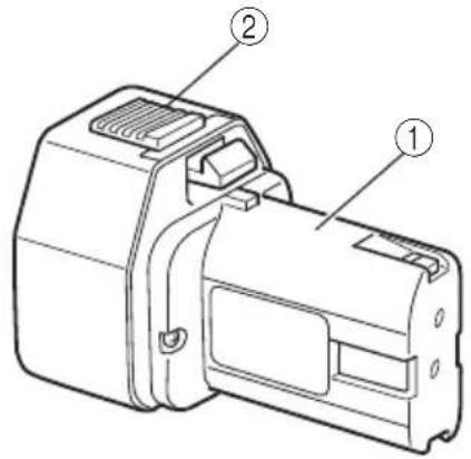
| 1 | Rechargeable battery Aufladbare batterie Batterie rechargeable | Batteria ricaricabile | ||
| 2 | Latch Verriegelung Taquet | Fermo | ||
| 3 | Pull out Herausziehen Tirevers l'extérieur | Estrarre | ||
| 4 | Insert Einsetzen Insérer | Inserire | ||
| 5 | Handle Handgriff Poignée | Impugnatura | ||
| 6 | Push Drücken Pousser | Spingere | ||
| 7 | Insert Einsetzen Insérer | Inserire | ||
| 8 | Pilot lamp Kontrollampe Lampe témoin | Spia | ||
| 9 | Hole for connecting the Arechargeable batteryschlußloch für Orifice de raAkkumulator | cordementede la batterie rechargeable | Foro di collegamentodella batteria ricericabilir | |
| 10 | mark zeichen | Indice de | Simbolo di | |
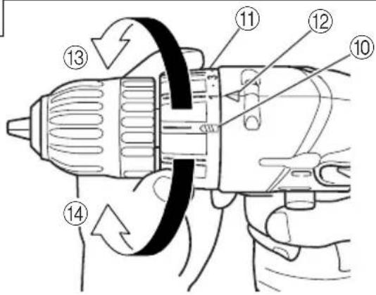
| 11 | Cluch dial | Kupplungsskala | Bague d'embrayage | Ghiera frizione |
| 12 | Triangle mark | Dreiecksmarkierung | Triangle | Simbolo del triangolo |
| 13 | Weak | Schwach | Faible | Debol |
| 14 | Strong | Stark | Fort | Forte |
| 15 | White line Weißen line | Trait blanc | Linea bianca | |
| 16 | Ring | Ring | Anneau | Anello |
| 17 | Sleeve | Manschette | Manchon | Collare |
| 18 | Tighten Anziehen | Serrer | Stringere | |
| 19 | Loosen | Lösen | Desserrer | Allentare |
| 20 | Trigger switch | Trigger | Déclencheur | Interruttore |
| 21 | Selector button | Wählhebel | Sélecteur | Selettore |
| 22 | and marksund lezeichenIndices et (L)Segno (R), (L) | |||
| Nederlands Español | Português | Ελληνικά | ||
| 1 | Oplaadbare batterij Bateria | a recargable | Bateria recarregável | Επαναφορτιζόμενη μπαταρία |
| 2 | Vergrendeling Cierre | Lingüeta | Μάνδαλο | |
| 3 | Uittrekken Sacar | Retirar | Τραβήξτε έξω | |
| 4 | Insteken Insertar | Inserir | Εισχωρήστε | |
| 5 | Handgreep Asidero | Cabo | Χερούλι | |
| 6 | Drukken Presionar | Empurrar | Σπρώξετε | |
| 7 | Insteken Insertar | Inserir | Εισχωρήσετε | |
| 8 | Kontrolelampje Lámpara | piloto | Lâmpada piloto | Δοκιμαστική λάμπα |
| 9 | Aansluiting voor Agujero oplaadbare accu la batería | para conectar recargable | Orifício para conectar a bateria recarregável | Τρύπα για την σύνδεση της επαναφορτιζόμενης μπαταρίας |
| 10 | -markering Marca del | Marca | σημάδι | |
| 11 | Koppelingsinstelling Disco de embrague | Disco de embreagem | Καντράν συμπλέκτη | |
| 12 | Driehoekje Marca de triángulo | Marca de triângulo | Σημάδι τριγώνου | |
| 13 | Zwak Débil | Fraco | Αδύνατο | |
| 14 | Sterk Fuerte | Forte | Δυνατό | |
| 15 | Witte lijn Linea blanca | Linha branca | άσπρη γραμμή | |
| 16 | Ring Anillo | Anel | Δακτύλιος | |
| 17 | Klembus Manguito | Manguito | Περίβλημα | |
| 18 | Aandraaien | Apretar | Apertar | Σφίξτε |
| 19 | Losdraaien Aflojar | Afrouxar | Χαλαρώστε | |
| 20 | Trekkerscvhakelaar | Conmutador de gatillo | Interruptor de comando | Σκανδάλη διακόπτης |
| 21 | Omzetschakelaar | Botón selector | Botão seletor | Κουμπί επιλογέα |
| 22 | en (L) merktekens | Marcas (R) y (L) | Marcas (R) e (L) | και (L) σημάδια |
GENERAL OPERATIONAL PRECAUTIONS
- Keep work area clean. Cluttered areas and benches invite accidents.
- Avoid dangerous environment. Don't expose power tools and charger to rain. Don't use power tools and charger in damp or wet locations. And keep work area well lit. Never use power tools and charger near flammable or explosive materials. Do not use tool and charger in presence of flammable liquids or gases.
- The appliance is not intended for use by young children or infirm persons without supervision. Young children should be supervised to ensure that they do not play with the appliance. All visitors should be kept safe distance from work area.
- Store idle tools and charger. When not in use, tools and charger should be stored in dry, high or locked-up place-out of reach of the children and infirm persons. Store tools and charger in a place where the temperature is less than 40^ C.
- Don't force tool. It will do the job better and safer at the rate for which it was designed.
- Use right tool. Don't force small tool or attachment to do the job of a heavy duty tool.
- Wear proper apparel. Do not wear loose clothing or jewelry. They can be caught in moving parts. Rubber gloves and non-skid footwears are recommended when working outdoor.
- Use eye protection with most tools. Also use face or dust mask if cutting operation is dusty.
- Don't abuse cord. Never carry charger by cord or yank it to disconnect from receptacle. Keep cord from heat, oil and sharp edges.
- Secure work. Use clamps or a vise to hold work. It's safer than using your hand and it frees both hands to operate tool.
- Don't overreach. Keep proper footing and balance at all times.
- Maintain tools with care. Keep tools sharp at all times, and clean for best and safest performance. Follow instructions for lubricating and changing accessories.
- When the charger is not in use, or when being maintained and inspected, disconnect its power cord from the receptacle.
- Remove chuck wrenches and wrenches. Form habit of checking to see that wrenches are removed from tool before turning it on.
- Avoid accidental starting. Don't carry tool with finger on switch.
- To avoid danger, always use only the specified charger.
- Use only genuine HiKOKI replacement parts.
- Do not use power tools for applications other than those specified in the Handling Instructions.
- To avoid personal injury, use only the accessories or attachment recommended in these handling instructions or in the HiKOKI catalog.
- Let only the authorized service center do the repairing. The Manufacturer will not be responsible for any damages or injuries caused by repair by the unauthorized persons or by mishandling of the tool.
-
To ensure the designed operational integrity of power tools and charger, do not remove installed covers or screws.
-
Always use the charger at the voltage specified on the nameplate.
- Do not touch movable parts or accessories unless the power source has been disconnected.
- Always charge the battery before use.
- Never use a battery other than that specified. Do not connect a usual dry cell, a rechargeable battery other than that specified or a car battery to the power tool.
- Do not use any transformer that has a booster.
- Do not charge the battery from an engine electric generator or DC power supply.
- Always charge indoors. Because the charger and battery heat slightly during charging, charge the battery in a place not exposed to direct sunlight; where the humidity is low and the ventilation is good.
- Before starting to work in a high place, pay attention to the activities below to make sure there are no people below.
- Use the exploded assembly drawing on this handling instructions only for authorized servicing.
- If the supply cord is damaged, it must be replaced by the manufacture or its service agent or a similarly qualified person in order to avoid a hazard.
PRECAUTIONS FOR CORDLESS DRIVER DRILL
- Always charge the battery at a temperature of 10 – 40°C. A temperature of less than 10°C will result in over charging which is dangerous. The battery cannot be charged at a temperature higher than 40°C. The most suitable temperature for charging is that of 20 – 25°C.
- When one charging is completed, leave the charger at least 15 minutes before the next charging of battery. Do not charge more than two batteries consecutively.
- Do not charge the battery for more than 2 hours. The battery will be fully charged in about 1 hour and charging should be stopped when 1 hour has elapsed from commencement. Disconnect the charger power cord from the receptacle.
- Do not allow foreign matter to enter the hole for connecting the rechargeable battery.
- Never disassemble the rechargeable battery and charger.
- Never short-circuit the rechargeable battery. Short-circuiting the battery will cause a great electric current and overheat. It results in burn or damage to the battery.
- Do not dispose of the battery in fire. If the battery is burnt, it may explode.
- When drilling in wall, floor or ceiling, check for buried electric power cord, etc.
- Bring the battery to the shop from which it was purchased as soon as the post-charging battery life becomes too short for practical use. Do not dispose of the exhausted battery.
- Using an exhausted battery will damage the charger.
-
Do not insert object into the air ventilation slots of the charger. Inserting metal objects or inflammables into the charger air ventilation slots will result in electrical shock hazard or damaged charger.
-
When mounting a bit into the keyless chuck, tighten the sleeve adequately. If the sleeve is not tight, the bit may slip or come off, causing injury.
SPECIFICATIONS
POWER TOOL
| Model DS7DF | ||||
| No-load speed 0 - 600 min | -1 | |||
| Capacity | Drilling(Thickness 1) | Wood(Thickness 18mm) | 15 mm | |
| Metal Steel: 10 mm,6mm) Aluminum: 10 mm | ||||
| Driving | Machine screw 6 mm | |||
| Wood screw | 5.1 mm (diameter) × 32 mm (length)(Requires a pilot hole) | |||
| Rechargeable battery | FEB7S: Ni-Cd 7.2 V EB71(1.4 Ah, 6 cells) (1.2 Ah, 6 cells) | |||
| Weight 1.3 kg 1.2 kg | ||||
CHARGER
| Model UC7SB | UC7SD | |
| Charging voltage | 7.2 V | |
| Weight | 1.0 kg | 1.1 kg |
STANDARD ACCESSORIES
| DS7DF | 1 Plus driver bit (No. 2×55L) ...... 1 |
| 2 Charger (UC7SB or UC7SD) ...... 1 | |
| 3 Plastic case ...... 1 |
Standard accessories are subject to change without notice.
OPTIONAL ACCESSORIES (sold separately)
- Battery (FEB7S, EB712S)

natural_image
Technical line drawing of a mechanical component with no visible text or symbolsOptional accessories are subject to change without notice.
APPLICATIONS
○Driving and removing of machine screws, wood screws, tapping screws, etc.
○Drilling of various metals.
○Drilling of various woods.
BATTERY REMOVAL/INSTALLATION
1. Battery removal
Hold the handle tightly and push the battery latch to remove the battery. (See Figs. 1 and 2)
CAUTION
Never short-circuit the battery.
2. Battery installation
Insert the battery while observing its direction. (See Fig. 2)
CHARGING
Before using the driver drill, charge the battery as follows.
1. Insert the battery into the charger.
Position the battery so that the nameplate faces toward the nameplate of the charger and press in the battery until it comes into contact with the bottom surface. (See Figs. 1 and 3)
2. Connect the charger power cord to the receptacle.
Connecting the power cord will turn on the charger (the pilot lamp lights up).
CAUTION
If the pilot lamp does not light up, pull out the power cord from the receptacle and check the battery mounting condition.
(1) Regarding recharging time
Depending on the combination of the charger and batteries, the charging time will become as shown in Table 1.
Table 1 Charging time (At 20°C)
| Battery\Charger | UC7SB / UC7SD |
| EB712S | Approx. 50 min. |
| FEB7S | Approx. 60 min. |
The battery charging time becomes longer when a temperature is low or the voltage of the power source is too low.
When the pilot lamp does not go off even if more than two hours have elapsed after starting of the charging, stop the charging and contact your HiKOKI AUTHORIZED SERVICE CENTER.
CAUTION
If the battery is heated due to direct sunlight, etc., just after operation, the charger pilot lamp may not light up. At that time, cool the battery first, then start charging.
- Disconnect the charger power cord from the receptacle.
- Hold the charger tight and pull out the battery.
Regarding electric discharge in case of new batteries, etc.
As the internal chemical substance of new batteries and batteries that have not been used for an extended period is not activated, the electric discharge might be low when using them the first and second time. This is a temporary phenomenon, and normal time required for recharging will be restored by recharging the batteries 2-3 times.
How to make the batteries perform longer.
(1) Recharge the batteries before they become completely exhausted.
When you feel that the power of the tool becomes weaker, stop using the tool and recharge its battery. If you continue to use the tool and exhaust the electric current, the battery may be damaged and its life will become shorter.
(2) Avoid recharging at high temperatures.
A rechargeable battery will be hot immediately after use. If such a battery is recharged immediately after use, its internal chemical substance will deteriorate, and the battery life will be shortened. Leave the battery and recharge it after it has cooled for a while.
PRIOR TO OPERATION
1. Setting up and checking the work environment
Check if the work environment is suitable by following the precautions.
HOW TO USE
1. Confirm the clutch dial position. (See Fig. 4)
The tightening torque of this unit can be adjusted according to the clutch dial position, at which the clutch dial is set.
(1) When using this unit as a screwdriver, line up the one of the numbers "1, 3, 5 ... 22" on the clutch dial, or the white dots with the triangle mark on the outer body.
(2) When using this unit as a drill, align the clutch dial drill mark “###” with the triangle mark on the outer body.
CAUTION
○The clutch dial cannot be set between the numbers "1, 3, 5 ... 22" or the white dots.
○Do not use with the clutch dial numeral between "22" and the white line at the middle of the drill mark. Doing so may cause damage. (See Fig. 5)
2. Tightening torque adjustment
(1) Tightening torque
Tightening torque should correspond in its intensity to the screw diameter. When too strong torque is used, the screw head may be broken or be damaged. Be sure to adjust the clutch dial position according to the screw diameter.
(2) Tightening torque indication
The tightening torque differs depending on the type of screw and the material being tightened.
The unit indicates the tightening torque with the numbers "1, 3, 5 ... 22" on the cluch dial, and the white dots. The tightening torque at position "1" is the weakest and the torque is strongest at the highest number. (See Fig. 4)
(3) Adjusting the tightening torque
Rotate the clutch dial and align the numbers "1, 3, 5 ... 22" on the clutch dial, or the white dots with the triangle mark on the outer body. Adjust the clutch dial in the weak or the strong torque direction according to the torque you need.
CAUTION
○The motor rotation may be locked to cease while the unit is used as a drill. While operating the driver drill, take care not to lock the motor.
○Too long hammering may cause the screw broken due to excessive tightening force.
3. The scope and suggestions for uses
The usable scope for various types of work based on the mechanical structure of this unit is shown in Table 2.
Table 2
| Work Suggestions | ||
| Drilling Steel U | Wood | |
| Use for drilling purpose. | ||
| Aluminum | ||
| Driving | Machine screw Use the bit or socket matching the screw diameter. | |
| Wood screw Use after drilling a pilot hole. | ||
4. Mounting and dismounting of the bit
(1) After inserting a driver bit, etc. into the keyless drill chuck, firmly grasp the ring and tighten the sleeve by turning it toward the right (in the clockwise direction as viewed from the front). (See Fig. 6)
○If the sleeve becomes loose during operation, tighten it further. The tightening force becomes stronger when the sleeve is tightened additionally.
(2) Dismounting the bit
Firmly grasp the ring and loosen the sleeve by turning it toward the left (in the counter-clockwise direction as viewed from the front). (See Fig. 6)
CAUTION
When it is no longer possible to loosen the sleeve, use a vise or similar instrument to secure the bit. Set the clutch mode between 1 and 10 and then turn the sleeve to the loose side (left side) while operating the clutch. It should be easy now to loosen the sleeve.
NOTE
○There is a plus driver bit on side of the main unit. The bit can be removed by pulling it forward. After using the bit, make sure to firmly attach it to the main body again.
5. Confirm that the battery is mounted correctly.
6. Check the rotation direction.
The bit rotates clockwise (viewed from the rear side) by pushing the R-side of the selector button. The L-side of the selector button is pushed to turn the bit counterclockwise. (See Fig. 7) (The L) and (remarks are provided on the body.)
7. Switch operation
When the trigger switch is pulled, the tool rotates. When the trigger is released, the tool stops.
☐The rotational speed of the drill can be controlled by varying the amount that the trigger switch is pulled. Speed is low when the trigger switch is pulled slightly and increases as the trigger switch is pulled more.
NOTE
○A peep sound may be produced when the motor is about to rotate; This is only a noise, not a machine failure.
MAINTENANCE AND INSPECTION
1. Inspecting the tool
Since use of as dull tool will degrade efficiency and cause possible motor malfunction, sharpen or replace the tool as soon as abrasion is noted.
2. Inspecting the mounting screws
Regularly inspect all mounting screws and ensure that they are properly tightened. Should any of the screws be loose, retighten them immediately. Failure to do so could result in serious hazard.
3. Cleaning on the outside
When the driver drill is stained, wipe with a soft dry cloth or a cloth moistened with soapy water. Do not use chloric solvents, gasoline or paint thinner, as they melt plastics.
4. Storage
Store the driver drill in a place in which the temperature is less than 40^ C and out of reach of children.
5. Service parts list
A : Item No.
B : Code No.
C: No. Used
D : Remarks
CAUTION:
Repair, modification and inspection of HiKOKI Power Tools must be carried out by a HiKOKI Authorized Service Center.
This Parts List will be helpful if presented with the tool to the HiKOKI Authorized Service Center when requesting repair or other maintenance.
In the operation and maintenance of power tools, the safety regulations and standards prescribed in each country must be observed.
MODIFICATIONS:
HiKOKI Power Tools are constantly being improved and modified to incorporate the latest technological advancements.
Accordingly, some parts (i.e. code numbers and/or design) may be changed without prior notice.
NOTE
Due to HiKOKI's continuing program of research and development, the specifications herein are subject to change without prior notice.
IMPORTANT
Correct connection of the plug
The wires of the mains lead are coloured in accordance with the following code:
Blue: - Neutral
Brown: – Live
As the colours of the wires in the mains lead of this tool may not correspond with the coloured markings identifying the terminals in your plug proceed as follows: The wire coloured blue must be connected to the terminal marked with the letter N or coloured black.
The wire coloured brown must be connected to the terminal marked with the letter L or coloured red.
Neither core must be connected to the earth terminal.
NOTE
This requirement is provided according to BRITISH STANDARD 2769: 1984.
Therefore, the letter code and colour code may not be applicable to other markets except United Kingdom.
Information concerning airborne noise and vibration
The measure values were determined according to EN50144.
The typical A-weighted sound pressure level does not exceed 70 dB (A).
Wear ear protection.
The typical weighted root mean square acceleration value: 0.4 m/s ^2
natural_image
Technical line drawing of a mechanical component with no visible text or symbolsnatural_image
Technical line drawing of a mechanical component with no visible text or symbolsnatural_image
Technical line drawing of a mechanical component with no visible text or symbolsnatural_image
Technical line drawing of a mechanical component with no visible text or symbolsnatural_image
Technical line drawing of a mechanical component with no visible text or symbolsnatural_image
Technical line drawing of a mechanical component with no visible text or symbolsnatural_image
Technical line drawing of a mechanical component with no visible text or symbols
natural_image
Line drawing of a quill pen with inkwell (no text or symbols)
natural_image
Line drawing of a quill pen with inkwell (no text or symbols)| English Nederlands | ||
| EC DECLARATION OF CONFORMITYWe declare under our sole responsibility that Cordless Driver Drill, identified by type and specific identification code *1), is in conformity with all relevant requirements of the directives *2) and standards *3). Technical fi le at *4) – See below.The European Standard Manager at the representative office in Europe is authorized to compile the technical fi le.The declaration is applicable to the product affi xed CE marking. | EC VERKLARING VAN CONFORMITEITWij verklaren onder onze eigen verantwoordelijkheid dat Snoerloze boor-schroefmachine, geïdentificeerd door het type en de specifieke identificatiecode*1), voldoet aan alle relevante bepalingen van de richtlijnen*2) en normen*3). Technische documentatie bij*4) – zie onder.De Europese Normen Manager bij de vertegenwoordiging in Europa is gemachtigd om het technisch dossier samen te stellen.Deze verklaring is van toepassing op producten voorzien van de CE-markeringen. | |
| Deutsch Español | ||
| EG-KONFORMITÄTSERKLÄRUNGWir erklären in alleiniger Verantwortung, dass der durch den Typ und den spezifischen Identifizierungscode *1) identifizierte Akku-Bohrschrauber allen einschlägigen Bestimmungen der Richtlinien *2) und Normen *3) entspricht. Technische Unterlagen unter *4) – Siehe unten.Die Leitung der repräsentativen Behörde für europäische Normen und Richtlinien ist berechtigt, die technischen Unterlagen zusammenzustellen.Die Erklärung gilt für die an dem Produkt angebrachte CE-Kennzeichnung. | DECLARACIÓN DE CONFORMIDAD DE LA CEDeclaramos bajo nuestra única responsabilidad que el Taladro atornillador a batería, identificado por tipo y por código de identificación específico *1), está en conformidad con todas las disposiciones correspondientes de las directivas *2) y de las normas *3). Documentación técnica en *4) – Ver a continuación.El Director de Normas Europeas en la oficina de representación en Europa está autorizado para elaborar el expediente técnico.La declaración se aplica al producto con marcas de la CE. | |
| Français Português | ||
| DECLARATION DE CONFORMITE CENous déclarons sous notre entière responsabilité que la perceuse-visseuse à batterie, identifiée par le type et le code d'identification spécifique *1) est en conformité avec toutes les exigences applicables des directives *2) et des normes *3). Dossier technique en *4) - Voir ci-dessous.Le Gestionnaire des normes européennes du bureau de représentation en Europe est autorisé à constituer le dossier technique.Cette déclaration s'applique aux produits désignés CE. | DECLARAÇÃO DE CONFORMIDADE CEDeclaramos, sob nossa única e inteira responsabilidade, que Berbequim Aparafusadora a Bateria, identificado por tipo e código de identificação específico *1), está em conformidade com todos os requerimentos relevantes das diretivas *2) e normas *3). Ficheiro técnico em *4)–Consulte abaixo.O Gestor de Normas Europeas no escritório de representação na Europa está autorizado a compilar o fi cheiro técnico.A declaração aplica-se aos produtos com marca CE. | |
| Italiano Ελληνικά | ||
| DICHIARAZIONE DI CONFORMITÀ CEDichiariamo sotto la nostra esclusiva responsabilità che il trapano-avvitatore a batteria, identificato dal tipo e dal codice identificativo specifico *1), è conforme a tutti i requisiti delle direttive *2) e degli standard *3). Documentazione tecnica presso *4) – Vedere sotto.Il gestore delle norme europee presso l'ufficio di rappresentanza in Europa è autorizzato a compilare il fascicolo tecnico.La dichiarazione è applicabile ai prodotti cui sono applicati i marchi CE. | ΕΚ ΔΗΛΩΣΗ ΕΝΑΡΜΟΝΙΣΜΟΥΔηλώνουμε με αποκλειστική μας ευθύνη ότι το Δραπανοκατσάβιδο μπαταρίας, το οποίο προσδιορίζεται από τον τύπο και ειδικό αναγνωριστικό κωδικό *1), είναι συμφωνο με όλες τις σχετικές απαιτήσεις των Οδηγιών *2) και στα σχετικά πρότυτα *3). Τεχνικό Αρχείο στο *4) – Δείτε παρακάτω.Ο Διαχειριστής Ευρωπαϊκών Προτύπων στο γραφείο εκπροσώπησης στην Ευρώπη είναι εξουσιοδοτημένος για τη σύνταξη του τεχνικού φακέλου.Η δήλωση ισχυει μόνο για το προϊόν που είναι τοποθετημένη σήμανοη CE. | |
| *1) DS7DF C326403R*2) 2006/42/EC, 2014/30/EU, 2014/35/EU, 2011/65/EU*3) EN60745-1:2009+A11:2010EN60745-2-1:2010EN60745-2-2:2010EN60335-1:2012+A11:2014EN60335-2-29:2004+A2:2010EN55014-1:2006+A1:2009+A2:2011EN55014-2:1997+A1:2001+A2:2008 | ||
| *4) Representative office in EuropeHikoki Power Tools Deutschland GmbHSiemensring 34, 47877 Willich, GermanyHead office in JapanKoki Holdings Co., Ltd.Shinagawa Intercity Tower A, 15-1, Konan 2-chome,Minato-ku, Tokyo, Japan | 29. 6. 2018Naoto YamashiroEuropean Standard Manager29. 6. 2018A. NakagawaCorporate Offi cer | |

- GENERAL OPERATIONAL PRECAUTIONS
- PRECAUTIONS FOR CORDLESS DRIVER DRILL
- SPECIFICATIONS
- OPTIONAL ACCESSORIES (sold separately)
- APPLICATIONS
- BATTERY REMOVAL/INSTALLATION
- Battery removal
- CAUTION
- Battery installation
- CHARGING
- Insert the battery into the charger.
- Connect the charger power cord to the receptacle.
- Regarding recharging time
- Regarding electric discharge in case of new batteries, etc.
- How to make the batteries perform longer.
- PRIOR TO OPERATION
- Setting up and checking the work environment
- HOW TO USE
- Confirm the clutch dial position. (See Fig. 4)
- Tightening torque adjustment
- The scope and suggestions for uses
- Mounting and dismounting of the bit
- NOTE
- Confirm that the battery is mounted correctly.
- Check the rotation direction.
- Switch operation
- MAINTENANCE AND INSPECTION
- Inspecting the tool
- Inspecting the mounting screws
- Cleaning on the outside
- Storage
- Service parts list
- CAUTION:
- MODIFICATIONS:
- IMPORTANT
- Information concerning airborne noise and vibration
Brand : HiKOKI
Model : DS 7DF
Category : Drill