
VL-WD812 - Doorbell PANASONIC - Free user manual and instructions
Find the device manual for free VL-WD812 PANASONIC in PDF.


| Product Type | Wireless Sensor Camera |
| Brand | Panasonic |
| Model | VL-WD812 |
| Dimensions (H × W × D) | Approx. 160 mm × 118 mm × 290 mm (including wall mount bracket) |
| Weight | Approx. 960 g |
| Power Source | 24 V DC, 0.4 A (via included power supply unit VL-PS240) |
| Power Consumption | Standby: approx. 1.5 W; Operation: approx. 4.5 W (LED off) / 8 W (LED on) |
| Image Sensor | 0.3 M pixel CMOS |
| Minimum Illuminance | 1 lx (when brightness setting is +3) |
| Field of View | Horizontal: approx. 53°, Vertical: approx. 41° |
| Detection Sensors | Pyroelectric infrared (heat sensor) and motion detection |
| Heat Sensor Detection Range | Horizontal: approx. 63°, Vertical: approx. 20°, Distance: approx. 5 m (at 20°C ambient) |
| Motion Detection Range | Horizontal: approx. 53°, Vertical: approx. 41° (adjustable range) |
| LED Lighting | 2 white LEDs; approx. 8.5 lx at 3 m front, 4 lx at 3 m off-center 20° |
| IP Rating | IP54 (when installed correctly with water protection measures) |
| Operating Temperature | Camera: -20°C to +50°C; Power supply: 0°C to +40°C |
| Operating Humidity | Up to 90% (non-condensing) |
| Transmitting Range | Approx. 100 m (line-of-sight from main monitor) |
| Frequency Range | 1.88 GHz - 1.90 GHz |
| Mounting | Wall mount with included bracket; Horizontal ±90°, Vertical facing forward to approx. 60° down |
| Heat Sensor Adjustable Angles | Manually adjustable to 2 angles |
| Cleaning | Disconnect power, wipe with soft cloth; do not spray water or use harsh chemicals |
| Compatibility | Works with Panasonic Video Intercom Systems: VL-SWD501, VL-SWD501U, VL-MWD501 |
Frequently Asked Questions - VL-WD812 PANASONIC
User questions about VL-WD812 PANASONIC
0 question about this device. Answer the ones you know or ask your own.
Ask a new question about this device
Download the instructions for your Doorbell in PDF format for free! Find your manual VL-WD812 - PANASONIC and take your electronic device back in hand. On this page are published all the documents necessary for the use of your device. VL-WD812 by PANASONIC.
USER MANUAL VL-WD812 PANASONIC
natural_image
Technical illustration of a mechanical sensor or connector assembly (no text or symbols visible)Panasonic
Information Guide
Wireless Sensor Camera
Model No. VL-WD812
Table of Contents
Introduction 2
General information 2
For your safety 3
Important safety instructions 3
For best performance 3
Other important information 4
Sensor operations 5
Controls 7
Cleaning 8
Specifications 8
Thank you for purchasing a Panasonic product.
Please read this manual before using the product and save it for future reference.
This product is not designed to be used for the prevention of property loss or intrusions.
In no event shall Panasonic be liable to any loss or damage arising out of the use of this product.
Installation Guide is supplied separately.
Introduction
This product is an additional product designed to be used with the following Panasonic Video Intercom Systems.
- VL-SWD501/VL-SWD501U (Main monitor station: VL-MWD501)
(The corresponding models are subject to change without notice.)
You must register this product with your Video Intercom System before it can be used.
- For registration information, refer to the Installation Guide of this product or the Operating Instructions of the Video Intercom System.
- This manual only covers the information and cautions required for the preparation and initial use of the product. For detailed information on how to operate the product, refer to the Operating Instructions of the Video Intercom System.
- The illustrations in the supplied manual(s) may vary slightly from the actual product.
- See the Installation Guide for information about accessories.
Product names used in this manual
| Model No. Product | name Name in this manual | |
| VL-WD812 Wireless sensor camera Camera | ||
| VL-MWD501 Main monitor | station Main monitor | |
| VL-WD613 Wireless monitor station Sub monitor | ||
- In this manual, the suffix of each model number (e.g., the "FX" in "VL-SWD501FX") is omitted unless necessary.
General information
- In the event of problems, you should contact your equipment supplier in the first instance.
Declaration of Conformity:
- Panasonic System Networks Co., Ltd. declares that this equipment (VL-WD812FX) is in compliance with the essential requirements and other relevant provisions of Radio & Telecommunications Terminal Equipment (R&TTE) Directive 1999/5/EC. Declarations of Conformity for the relevant Panasonic products described in this manual are available for download by visiting:
http://www.ptc.panasonic.eu
Contact to Authorised Representative:
Panasonic Testing Centre
Panasonic Marketing Europe GmbH
Winsbergring 15, 22525 Hamburg, Germany
Ecodesign information
Ecodesign information under EU Regulation (EC) No. 1275/2008 amended by (EU) Regulation No. 801/2013. From 1 January 2015.
Please visit here: www.ptc.panasonic.eu
Click [Downloads]
→ Energy related products information (Public)
Power consumption in networked standby and guidance are mentioned in the web site above.
For your future reference
We recommend keeping a record of the following information to assist with any repair under warranty.
| Serial No. | Date of purchase |
| (found on the rear of the product) | |
| Name and address of dealer |
Attach your purchase receipt here.
For your safety
To prevent severe injury and loss of life/property, read this section carefully before using the product to ensure proper and safe operation of your product.

WARNING
Preventing fire, electric shock and short circuits
- Use only the power source marked on the product. If you are not sure of the type of power supplied to your home, consult your dealer or local power company.
- Use only the specified power supply unit.
- Do not attempt to disassemble or modify this product. Contact an authorised service centre for repairs.
- Never touch the power supply unit with wet hands.
- Do not touch the power supply unit during an electrical storm.
- Never spill liquids on the power supply unit (the power supply unit is for indoor use only). Do not directly spray the camera with water from a hose or other objects. Never spill any liquid inside the product.
If the power supply unit or internal parts of the camera become wet, turn off the circuit breaker and contact an authorised service centre.
- Never put metal objects inside the product. If metal objects enter the product, turn off the circuit breaker and contact an authorised service centre.
- Do not perform any actions (such as fabricating, twisting, stretching, bundling, forcibly bending, damaging, altering, exposing to heat sources, or placing heavy objects on the power cable) that may damage the power cable. Using the product with a damaged power cable may cause electric shock, short circuits, or fire. Contact an authorised service centre for repairs.
- Turn off a circuit breaker if the product emits smoke, an abnormal smell or makes unusual noise, or if the product has been dropped or physically damaged. These conditions can cause fire or electric shock. Confirm that smoke has stopped emitting and contact an authorised service centre.
Preventing accidents and injuries
- Do not pull or hang off the product or power cable. Pulling out the power cable may cause electric shock or cause the camera to fall down, resulting in injury.
- Do not drop the product or expose it to a strong impact. To prevent the product from falling, securely fix the safety wire to the product and a wall.
- The sensor range cap may become a choking hazard. Keep it out of reach of children. If you suspect a child has swallowed the sensor range cap, seek medical advice immediately.

CAUTION
Preventing fire and electric shock
- Do not use the product in areas that are exposed to moisture, steam, or oily smoke, or areas that have excessive dust.
Preventing accidents and injuries
- Do not put your ear(s) near the speaker, as loud sounds emitted from the speaker may cause hearing impairment.
- Do not look directly at the LED lights when they are lit. Failure to do so may cause damage to eyes.
Important safety instructions
When using this product, basic safety precautions should always be followed to reduce the risk of fire, electric shock, or personal injury.
- Use only the power supply unit indicated in this manual.
SAVE THESE INSTRUCTIONS
For best performance
- Do not allow the lens cover (①) or the heat sensor (②) to become scratched or dirty.
(This may cause image quality to be reduced, incorrect detections, malfunctions, or damage to the lens cover and heat sensor.)

- Do not expose this product to direct sunlight or other forms of powerful light such as halogen lights for long periods of time. (This may damage the image sensor.)
Other important information
Privacy and rights of portrait
See the Installation Guide for the camera or the Operating Instructions of the Video Intercom System for more information.
Camera image quality
- Camera images may have the following characteristics.
– Colours in images may differ from the actual colours. - When there is light at the back of the object, faces may appear dark.
– Image quality may be reduced in dark locations.
– Images may appear hazy when there are outdoor lights in use.
- Effect of brightness and distance on image quality: Distinguishing faces is difficult in the following situations.
- When the person is too far (over approx. 3 m) from the camera even when the surrounding area is bright.
(Depending on the viewing angle or the conditions when images were viewed, such as when there are shadows or backlighting, faces may not be distinguishable even when the person is within 3 m of the camera.)
– In the late afternoon and at night, or other times when the surrounding area is dark. (This may reduce image quality.)
- When people are moving (which causes blurring) in front of the camera.
Repairing, transferring, disposing, or returning the product
Requesting repairs for the product
- Note that the settings of the camera may be altered or changed to the default settings during repairs.
Note for product disposal, transfer, or return
- Use the main monitor to perform the [Initialize settings] setting for the camera. (→ See the Operating Instructions of the Video Intercom System.)
Settings are returned to their default values when initialization is performed.
Information for Users on Collection and Disposal of Old Equipment and used Batteries
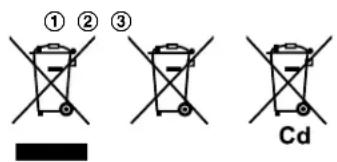
These symbols (①, ②, ③) on the products, packaging, and/or accompanying documents mean that used electrical and electronic products and batteries should not be mixed with general household waste.
For proper treatment, recovery and recycling of old products and used batteries, please take them to applicable collection points, in accordance with your national legislation and the Directives 2002/96/EC and 2006/66/EC.
By disposing of these products and batteries correctly, you will help to save valuable resources and prevent any potential negative effects on human health and the environment which could otherwise arise from inappropriate waste handling.
For more information about collection and recycling of old products and batteries, please contact your local municipality, your waste disposal service or the point of sale where you purchased the items.
Penalties may be applicable for incorrect disposal of this waste, in accordance with national legislation.
For business users in the European Union
If you wish to discard electrical and electronic equipment, please contact your dealer or supplier for further information.
Information on Disposal in other Countries outside the European Union
These symbols (①, ②, ③) are only valid in the European Union. If you wish to discard these items, please contact your local authorities or dealer and ask for the correct method of disposal.
Note for the battery symbol
This symbol (②) might be used in combination with a chemical symbol (③). In this case it complies with the requirement set by the Directive for the chemical involved.
Others
- It is prohibited to disassemble or modify this product. Contact the dealer where you purchased this product for repair.
- When power fails, this product cannot be used.
- Panasonic may not be liable for damages due to external factors such as power failures.
- Adjust the speaker volume settings ([Sensor trigger sound], [Warning sound], and [Owner's voice volume]) appropriately so that sound from the camera does not make a disturbance in the area around the camera. (→ See the Operating Instructions of the Video Intercom System.)
- When the camera is no longer used.
- When the camera's registration is cancelled with the main monitor, disconnect the camera's power supply in order to prevent incorrect operations. (→ See the Operating Instructions of the Video Intercom System for information about cancelling the camera's registration.)
- Remove the camera from its mounted location when it is no longer in use. (Contact our service
personnel for information about removing the camera.)
Sensor operations
The camera has 2 sensors: the motion detection sensor and the heat sensor.
Please read the following information about the camera's motion detection sensor and heat sensor before deciding where to mount the camera.
Sensor characteristics and detection range
| Motion detection sensor Heat sensor | ||
| Detection method | The camera detects changes in the images being displayed.The camera detects changes in the brightness levels of moving objects. | The camera detects temperature differences of objects in the images being displayed.The heat sensor uses infrared rays to detect temperature differences within its range that are emitted naturally by people, animals, etc. |
| Main characteristics | Easily detects movement in the daytime or when it is bright.Movement may be incorrectly detected when the moving object and the background have a similar colour.Movement may be incorrectly detected when there are sudden changes to the overall brightness levels such as when external lights are used. | Easily detects when there is a big difference between the temperatures of objects and the surrounding environment, such as in winter or late at night.The sensor cannot easily detect when there is no difference between the temperatures of objects and the surrounding environment, such as in summer or during the daytime.If the camera is mounted facing a road, the sensor may detect incorrectly due to interference caused by the heat from passing cars. |
| Detection range | Entire viewed image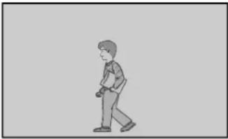 The detection range can be reduced.(See the [Motion detection range] setting in the Operating Instructions of the Video Intercom System.) The detection range can be reduced.(See the [Motion detection range] setting in the Operating Instructions of the Video Intercom System.) | Part of viewed image (grey area) The detection range can be changed.(See the information about adjusting the detection range in the Installation Guide.) The detection range can be changed.(See the information about adjusting the detection range in the Installation Guide.) |
| Detection characteristics | |
| Easy to detect/ Difficult to detect |  1 It is difficult to detect movement directly towards the front of the camera.2 It is easy to detect movement sideways in front of the camera.3 Detection range4 Camera 1 It is difficult to detect movement directly towards the front of the camera.2 It is easy to detect movement sideways in front of the camera.3 Detection range4 Camera |
- The motion detection sensor and heat sensor are not designed to be used in situations that require high reliability. We do not recommend use of the motion detection sensor and heat sensor in these situations.
- Panasonic takes no responsibility for any injury or damages caused by use of the motion detection sensor and heat sensor.
Sensor operating range
In the default settings, the motion detection sensor and heat sensor operate in the following way depending on changes to the brightness levels.

- The brightness level is automatically determined by the camera when viewing images.
A timer can be configured to switch the modes between day and night modes at specified times. (See the [Day and night switch] setting in the Operating Instructions of the Video Intercom System.) - The settings can be configured to match the installation environment by only operating the motion detection sensor and heat sensor at certain times, for example only during the day or only at night. (See the [Heat sensor detection] and [Motion detection] settings in the Operating Instructions of the Video Intercom System.)
Controls

Rear view

① Indicator lamp (See the following explanation.)
② LED lights
- Automatically lights when it is dark and the camera is monitoring or when sensors are operating. (The LED lights are designed to be used as warning lights for intruders and are not meant to be used for illumination.)
③ Lens cover
- Contains a lens and a brightness sensor. (See the following explanation.)
④ Sensor range cap (standard type)
- 4 types of lens caps (accessories) can be fitted as required. (→ Installation Guide)
⑤ Heat sensor
• Detects changes in temperature. (→ page 5)
⑥ Microphone
⑦ Speaker
⑧ Safety wire
⑨ Heat sensor lever
• Used to change the angle of the heat sensor. (→ Installation Guide)
⑩ Register button (behind the register button cover)
- The register button is located behind the register button cover. Used when registering the camera to the main monitor. (→ Installation Guide)
Brightness sensor
Determines whether to light the LED lights by detecting the brightness of the surrounding area.
Indicator lamp
After the camera has been registered to the main monitor, you can check the camera's status and the wireless signal status from the main monitor by checking the status of the indicator lamp.
| Indicator display Camera's | status | |
| Transmission status | Flashing green (fast) | A sensor has been triggered and the camera is calling the main monitor. |
| Flashing green (slow) | The camera is transmitting data to the main monitor. | |
| Indicator display Camera's status | ||
| Signal status(during standby) | Lit green Strong Indicators the signal status from the main monitor. | |
| Lit orange | [CKBA]WeakWe recommend installing the camera in an area where the status indicator is strong (when the indicator is lit green). | |
| Lit red | ||
| Flashing red Transmissions cannot be sent because there is no signal (out of range). | ||
- Depending on how [Indicator lamp] is configured, the indicator may always be off or only be lit when transmitting (when monitoring or talking) with the main monitor. (See the [Indicator lamp] setting in the Operating Instructions of the Video Intercom System.)
Cleaning
In order to prevent incorrect sensor detections, disconnect the power from the camera when cleaning the camera.
Wipe the camera with a soft cloth.
- When the camera is excessively dirty, wipe it with a slightly damp cloth.
Important:
- Do not directly spray the camera with water from a hose or other objects. (There is a risk of fire or electric shock if water enters inside the camera.)
- Do not use any cleaning products that contain strong or weak detergents, alcohol, polish powder, powder soap, benzine, thinner, wax, petroleum, or boiling water. Also do not spray the product with insecticide, glass cleaner, or hair spray. This may cause a change in colour or quality of the camera.
Specifications
| Power source | Power supply unit (VL-PS240)24 V DC, 0.4 A |
| Power consumption During standby: approx. 1.5 WDuring operation: approx. 4.5 W (when the LED lights are not lit), approx. 8 W (when the LED lights are lit) | |
| Dimensions (mm) (height × width × depth) | Approx. 160×118×290 (when the camera is front facing and including the wall mount bracket) |
| Mass (weight) Approx. 960 g | |
| Installation method Wall mount (wall mount bracket supplied) | |
| Operating environment Ambient temperature: approx. -20 °C to +50 °CRelative humidity (non-condensing): up to 90 % | |
| Transmitting range Approx. 100 m | (line-of-sight distance from the main monitor) |
| Frequency range 1.88 GHz to 1.90 GHz | |
| Image sensor 0.3 M pixel CMOS | |
| Minimum illuminance required | 1 lx*1 |
| Focal length Fixed (0.4 m - infinity) | |
| Angular field of view (camera angle) | Horizontal: approx. 53°, vertical: approx. 41° |
| Sensor detection method Pyroelectric infrared sensor (heat sensor) and motion detection | |
| Sensor detection range | Heat sensor (when the surrounding temperature is approx. 20 °C)Horizontal: approx. 63°, vertical: approx. 20°, detection range: approx. 5 mMotion detection sensorHorizontal: approx. 53°, vertical: approx. 41° |
| Lighting method | 2 white LED lights*2 |
| IP rating | IP54*3 |
| Adjustable mounting angles Horizontal: ± 90irc , vertical: facing forward - facing down approx. 60irc (adjustable when mounting) | |
| Heat sensor adjustable angles Manually adjustable to 2 angles | |
Power supply unit (VL-PS240) (indoor use only)
| Power source Input: 220-240 V AC | 0.2 A, 50/60 HzOutput: 24 V DC, 0.6 A |
| Dimensions (mm) (height × width × depth) | Approx. 116×100×54 (excluding protruding sections) |
| Mass (weight) Approx. 230 g | |
| Operating environment Ambient temperature: approx. 0 °C to +40 °CRelative humidity (non-condensing): up to 90 % | |
| Installation method Attach to DIN rail | |
*1 The minimum illuminance required when the camera's [Brightness] setting is set to [+3].
*2 Approx. 8.5 lx when 3 m in front of the camera, and approx. 4 lx when 3 m away and 20° to the left or right of the camera.
*3 Water resistance is only assured if the camera is installed correctly according to the instructions in the Installation Guide, and appropriate water protection measures are taken. Do not install the camera in areas directly exposed to water or rain.
Note:
- Design and specifications are subject to change without notice.
- Names, company names, product names, software names, and logos mentioned in this manual are trademarks or registered trademarks of the companies concerned.
Notes
Panasonic
natural_image
Technical line drawing of a mechanical component with cylindrical and rectangular parts (no text or symbols)Panasonic Testing Centre
Panasonic Marketing Europe GmbH
Widok z tyłu

natural_image
Technical illustration of a mechanical component with cylindrical and rectangular parts (no text or symbols)Panasonic Testing Centre
Panasonic Marketing Europe GmbH
Winsbergring 15, 22525 Hamburg, Germania
natural_image
Simple diagram with two horizontal bars and double arrows, no text or symbols presentVedere din spate

natural_image
Technical illustration of a mechanical component with cylindrical and rectangular parts (no text or symbols)Tartalomjegyzék
Bevezetés 2
Panasonic Testing Centre
Panasonic Marketing Europe GmbH
Hátulnézet

- Panasonic
- Information Guide
- Table of Contents
- Introduction
- General information
- Declaration of Conformity:
- Ecodesign information
- For your future reference
- For your safety
- WARNING
- Preventing fire, electric shock and short circuits
- Preventing accidents and injuries
- CAUTION
- Preventing fire and electric shock
- Important safety instructions
- SAVE THESE INSTRUCTIONS
- For best performance
- Other important information
- Privacy and rights of portrait
- Camera image quality
- Repairing, transferring, disposing, or returning the product
- Requesting repairs for the product
- Note for product disposal, transfer, or return
- Information for Users on Collection and Disposal of Old Equipment and used Batteries
- For business users in the European Union
- Information on Disposal in other Countries outside the European Union
- Note for the battery symbol
- Others
- Sensor operations
- Sensor operating range
- Controls
- Brightness sensor
- Indicator lamp
- Cleaning
- Wipe the camera with a soft cloth.
- Important:
- Note:
- Tartalomjegyzék
Brand : PANASONIC
Model : VL-WD812
Category : Doorbell