
VL-VM801 - Doorbell PANASONIC - Free user manual and instructions
Find the device manual for free VL-VM801 PANASONIC in PDF.


| Type de produit | Video Intercom System - Lobby Station (Extension Cable included) |
| Brand | Panasonic |
| Model | VL-VM801 (part of VL-VM series) |
| Power Source | 24 V DC, 0.6 A (VL-PS240) or 2.5 A (VL-PS2410) power supply unit (sold separately) |
| Power Consumption (Lobby Station) | Standby: 1.8 W, Operating: 9.9 W |
| Dimensions (Flush Mount, Small Type) | Approx. 226 mm (H) x 130 mm (W) x 9 mm (D) |
| Dimensions (Flush Mount, Large Type) | Approx. 315 mm (H) x 130 mm (W) x 9 mm (D) |
| Weight (Flush Mount, Small Type) | Approx. under 1.3 kg |
| Weight (Flush Mount, Large Type) | Approx. under 1.8 kg |
| Image Sensor | 1/4 inch CMOS sensor (approx. 1M pixels) |
| Viewing Angle | Horizontal: approx. 170°, Vertical: approx. 110° |
| Minimum Illuminance | 1 lx (within approx. 50 cm from camera lens) |
| Lighting Method | White coloured LED lights |
| IP Rating | IP55 (when installed correctly) |
| IK Rating | IK08 |
| Audio Guidance Languages | English, German, French, Italian, Spanish, Dutch, Arabic, Persian |
| Talking Method | Hands-free |
| Operating Environment | Ambient temperature: -15 °C to +55 °C, Relative humidity up to 90% (non-condensing) |
| Installation Method | Flush mount or surface mount (using optional back box and surface mount cover) |
| External Material | Stainless steel (surface mount cover), Aluminum (partially PC and ABS) |
| Extension Cable (VL-VM801) | Approx. 1 m, used to connect two frames of a lobby station |
| Maximum Number of Rooms | Up to 32 rooms (depending on configuration) |
| Wiring Methods | Star wiring and bus wiring supported |
Frequently Asked Questions - VL-VM801 PANASONIC
User questions about VL-VM801 PANASONIC
0 question about this device. Answer the ones you know or ask your own.
Ask a new question about this device
Download the instructions for your Doorbell in PDF format for free! Find your manual VL-VM801 - PANASONIC and take your electronic device back in hand. On this page are published all the documents necessary for the use of your device. VL-VM801 by PANASONIC.
USER MANUAL VL-VM801 PANASONIC
Installation and Operating Instructions
Video Intercom System — Lobby station/Distributor
Model No. VL-VM series / VL-VM701
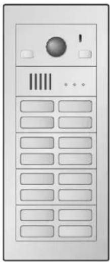
natural_image
Front view of a server rack with control panel and indicator lights (no text or symbols visible)Lobby station (16 call buttons)
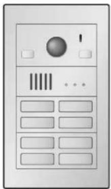
natural_image
Front view of a mobile phone interface with buttons and a circular display (no text or symbols visible)Lobby station (8 call buttons)
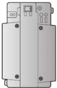
natural_image
Technical illustration of a mechanical device with mounting holes and a central control panel (no text or symbols)Distributor (VL-VM701) ^*1
Thank you for purchasing a Panasonic product.
Please follow all instructions in this document and save it for future reference.
Carefully read the information found in the section titled "2.1 Important safety information" in particular.
*1 In India, VL-VM701 is not sold and bus wiring is not available.
This system is an auxiliary system; it is not designed to provide complete protection from property loss.
Panasonic will not be held responsible in the event that property loss occurs while this system is in operation.
Note to the installer
- This document includes instructions for both installation and operation. See the section titled "4 Installation" for installation instructions.
- Please read this document carefully, and install the product safely and correctly by following the instructions.
- Only use attachments/accessories specified by the manufacturer.
- The installation shall be carried out in accordance with all applicable installation rules.
1. Introduction
1.1 System overview ......3
2. Important Information
2.1 Important safety information ....7
2.2 Important safety instructions ....8
2.3 Privacy and rights of portrait ....8
2.4 Disclaimer 8
2.5 Other important information ....8
2.6 General information ....8
2.7 For India only 9
2.8 For Europe 9
3. Preparation
3.1 System devices ....10
3.2 Device diagrams .....16
3.3 Specifications ....18
4. Installation
4.1 Installation cautions ......20
4.2 Installing the power supply unit (sold separately) 20
4.3 Installing the lobby station .....25
4.4 Installing the extension box (sold separately) 34
4.5 Installing the distributor (sold separately) 35
4.6 Wiring Connections ......36
4.7 DIP switch settings ....40
4.8 Distributor POWER and ACCESS indicators ....43
4.9 Connecting other devices ....43
4.10 Room name plates ....44
5. Basic Operations
5.1 System conditions and limitations .....45
5.2 Lobby station operations .....45
6. Other information
6.1 Basic troubleshooting ....46
6.2 Cleaning 47
6.3 Terms and illustrations in this document 47
6.4 Trademarks (for France) 47
1.1 System overview
This document explains how to install and configure a Video Intercom System for Apartment Complexes comprised of the VL-VM series devices.
Additionally, general information is provided for connecting other devices to the system.
1.1.1 Main features
Easy installation
- A flexible system that accommodates up to 32 rooms can be designed by combining call button modules.
- The lobby station supports the two main wiring methods (star and bus).
Easy maintenance
- Our unique front-access nameplates are easily changed, even after the lobby station is installed.
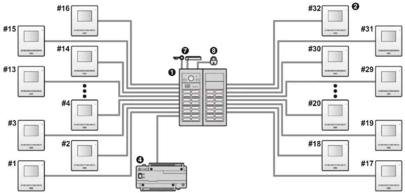
1.1.2 System configuration
Star wiring example
Example: 32 call buttons on the lobby station
flowchart
graph TD
    subgraph Terminal_1
        A1["#1"] --> B1["#2"]
        A2["#3"] --> B2["#4"]
        A3["#13"] --> B3["#14"]
        A4["#15"] --> B4["#16"]
    end
    subgraph Terminal_2
        B5["#18"] --> C5["#20"]
        B6["#19"] --> C6["#29"]
        B7["#30"] --> C7["#31"]
        B8["#16"] --> C8["#32"]
    end
    subgraph Terminal_3
        C9["#17"] --> D9["#18"]
    end
    Terminal_4["Device 4"] --> B1
    Terminal_5["Device 5"] --> B2
    Terminal_6["Device 6"] --> B3
    Terminal_7["Device 7"] --> B4
    Terminal_8["Device 8"] --> B5
    Terminal_9["Device 9"] --> B6
    Terminal_10["Device 10"] --> B7
    Terminal_11["Device 11"] --> B8
    Terminal_12["Device 12"] --> B9
    Terminal_13["Device 13"] --> B10
    Terminal_14["Device 14"] --> B11
    Terminal_15["Device 15"] --> B12
    Terminal_16["Device 16"] --> B13
    Terminal_17["Device 17"] --> B14
    Terminal_18["Device 18"] --> B15
    Terminal_19["Device 19"] --> B20
    Terminal_20["Device 20"] --> B21
    Terminal_21["Device 21"] --> B22
    Terminal_22["Device 22"] --> B23
    Terminal_23["Device 23"] --> B24
    Terminal_24["Device 24"] --> B25
    Terminal_25["Device 25"] --> B26
    Terminal_26["Device 26"] --> B27
    Terminal_27["Device 27"] --> B28
    Terminal_28["Device 28"] --> B29
    Terminal_29["Device 29"] --> B30
    Terminal_30["Device 30"] --> B31
    Terminal_31["Device 31"] --> B32
    Terminal_32["Device 32"] --> B33
    Terminal_33["Device 33"] --> B34
    Terminal_34["Device 34"] --> B35
    Terminal_35["Device 35"] --> B36
    Terminal_36["Device 36"] --> B37
    Terminal_37["Device 37"] --> B38
    Terminal_38["Device 38"] --> B39
    Terminal_39["Device 39"] --> B40
    Terminal_40["Device 40"] --> B41
    Terminal_41["Device 41"] --> B42
    Terminal_42["Device 42"] --> B43
    Terminal_43["Device 43"] --> B44
    Terminal_44["Device 44"] --> B45
    Terminal_45["Device 45"] --> B46
    Terminal_46["Device 46"] --> B47
    Terminal_47["Device 47"] --> B48
    Terminal_48["Device 48"] --> B49
    Terminal_49["Device 49"] --> B50
    Terminal_50["Device 50"] --> B51
    Terminal_51["Device 51"] --> B52
    Terminal_52["Device 52"] --> B53
    Terminal_53["Device 53"] --> B54
    Terminal_54["Device 54"] --> B55
    Terminal_55["Device 55"] --> B56
    Terminal_56["Device 56"] --> B57
    Terminal_57["Device 57"] --> B58
    Terminal_58["Device 58"] --> B59
    Terminal_59["Device 59"] --> B60
    Terminal_60["Device 60"] --> B61
    Terminal_61["Device 61"] --> B62
    Terminal_62["Device 62"] --> B63
    Terminal_63["Device 63"] --> B64
    Terminal_64["Device 64"] --> B65
    Terminal_65["Device 65"] --> B66
    Terminal_66["Device 66"] --> B67
    Terminal_67["Device 67"] --> B68
    Terminal_68["Device 68"] --> B69
Bus wiring example
Example 1: 16 call buttons on the lobby station
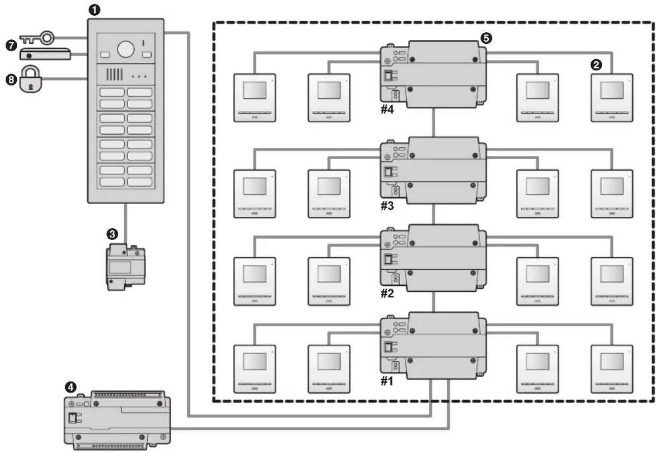
flowchart
graph TD
    A["Device ①"] --> B["Switch"]
    C["Switch ⑦"] --> A
    D["Switch ⑧"] --> A
    E["Switch ③"] --> F["Computer"]
    G["Switch ④"] --> H["Computer"]
    I["Switch ⑤"] --> J["Computer"]
    K["Switch ②"] --> L["Computer"]
    M["Switch ④"] --> N["Computer"]
    O["Switch ③"] --> P["Computer"]
    Q["Switch ②"] --> R["Computer"]
    S["Switch ①"] --> T["Computer"]
    U["Switch ⑤"] --> V["Computer"]
    W["Switch ②"] --> X["Computer"]
    Y["Switch ③"] --> Z["Computer"]
    AA["Switch ④"] --> AB["Computer"]
Bus wiring example
Example 2: 32 call buttons on the lobby station/6 lobby stations
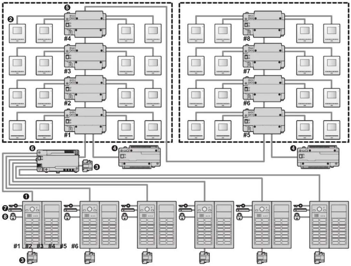
flowchart
graph TD
    subgraph Group1
        A1["②"] --> B1["#4"]
        A2["②"] --> B2["#3"]
        A3["②"] --> B3["#2"]
        A4["②"] --> B4["#1"]
        A5["②"] --> B5["③"]
        A6["②"] --> B6["④"]
        A7["②"] --> B7["⑤"]
        A8["②"] --> B8["⑥"]
        A9["②"] --> B9["⑦"]
        A10["②"] --> B10["⑧"]
    end

    subgraph Group2
        A10["②"] --> B10["③"]
        A11["②"] --> B11["④"]
        A12["②"] --> B12["⑤"]
        A13["②"] --> B13["⑥"]
        A14["②"] --> B14["⑦"]
        A15["②"] --> B15["⑧"]
    end

    subgraph Group3
        A15["②"] --> B15["③"]
        A16["②"] --> B16["④"]
        A17["②"] --> B17["⑤"]
        A18["②"] --> B18["⑥"]
        A19["②"] --> B19["⑦"]
    end

    subgraph Group4
        A19["②"] --> B20["③"]
        A20["②"] --> B20["④"]
        A21["②"] --> B21["⑤"]
        A22["②"] --> B22["⑥"]
        A23["②"] --> B23["⑦"]
    end

    Group4 --> Group5
    Group5 --> Group6
    Group6 --> Group7
    Group7 --> Group8
    Group8 --> Group9
    Group9 --> Group10
    Group10 --> Group11
    Group11 --> Group12
    Group12 --> Group13
    Group13 --> Group14
    Group14 --> Group15
    Group15 --> Group16
    Group16 --> Group17
    Group17 --> Group18
    Group18 --> Group19
    Group19 --> Group20
    Group20 --> Group21
    Group21 --> Group22
    Group22 --> Group23
    Group23 --> Group24
    Group24 --> Group25
    Group25 --> Group26
    Group26 --> Group27
    Group27 --> Group28
    Group28 --> Group29
    Group29 --> Group30
    Group30 --> Group31
    Group31 --> Group32
    Group32 --> Group33
    Group33 --> Group34
    Group34 --> Group35
    Group35 --> Group36
    Group36 --> Group37
    Group37 --> Group38
    Group38 --> Group39
    Group39 --> Group40
    Group40 --> Group41
    Group41 --> Group42
    Group42 --> Group43
    Group43 --> Group44
    Group44 --> Group45
    Group45 --> Group46
    Group46 --> Group47
    Group47 --> Group48
    Group48 --> Group49
    Group49 --> Group50
    Group50 --> Group51
    Group51 --> Group52
    Group52 --> Group53
    Group53 --> Group54
    Group54 --> Group55
    Group55 --> Group56
    Group56 --> Group57
    Group57 --> Group58
    Group58 --> Group59
    Group59 --> Group60
    Group60 --> Group61
    Group61 --> Group62
    Group62 --> Group63
    Group63 --> Group64
    Group64 --> Group65
    Group65 --> Group66
    Group66 --> Group67
    Group67 --> Group68
    Group68 --> Group69
    Group69 --> Group70
    Region 1: Server 1: Server 1.0, Server 2: Server 2.0, Server 3: Server 3.0, Server 4: Server 4.0, Server 5: Server 5.0, Server 6: Server 6.0, Server 7: Server 7.0, Server 8: Server 8.0, Server 9: Server 9.0, Server 10: Server 10.0, Server 11: Server 11.0, Server 12: Server 12.0, Server 13: Server 13.0, Server 14: Server 14.0, Server 15: Server 15.0, Server 16: Server 16.0, Server 17: Server 17.0, Server 18: Server 18.0, Server 19: Server 19.0, Server 20: Server 20.0, Server 21: Server 21.0, Server 22: Server 22.0, Server 23: Server 23.0, Server 24: Server 24.0, Server 25: Server 25.0, Server 26: Server 26.0, Server 27: Server 27.0, Server 28: Server 28.0, Server 29: Server 29.0, Server 30: Server 30.0, Server 31: Server 31.0, Server 32: Server 32.0, Server 33: Server 33.0, Server 34: Server 34.0, Server 35: Server 35.0, Server 36: Server 36.0, Server 37: Server 37.0, Server 38: Server 38.0, Server 39: Server 39.0, Server 40: Server 40.0, Server 41: Server 41.0, Server 42: Server 42.0, Server 43: Server 43.0, Server 44: Server 44.0, Server 45: Server 45.0, Server 46: Server 46.0, Server 47: Server 47.0, Server 48: Server 48.0, Server 49: Server 49.0, Server 50: Server 50.0, Server 51: Server 51.0, Server 52: Server 52.0, Server 53: Server 53.0, Server 54: Server 54.0, Server 55: Server 55.0, Server 56: Server 56.0, Server 57: Server 57.0, Server 58: Server 58.0, Server 59: Server 59.0, Server 60: Server 60.0, Server 61: Server 61.0, Server 62: Server 62.0, Server 63: Server 63.0, Server 64: Server 64.0, Server 65: Server 65.0, Server 66: Server 66.0, Server 67: Server 67.0, Server 68: Server 68.0, Server 69: Server 69.0, Server 70: Server 70.0, Server 71: Server 71.0, Server 72: Server 72.0, Server 73: Server 73.0, Server 74: Server 74.0, Server 75: Server 75.0, Server 76: Server 76.0, Server 77: Server 77.0, Server 78: Server 78.0, Server 79: Server 79.0, Server 80: Server 80.0, Server 81: Server 81.0, Server 82: Server 82.0, Server 83: Server 83.0, Server 84: Server 84.0, Server 85: Server 85.0, Server 86: Server 86.0, Server 87: Server 87.0, Server 88: Server 88.0, Server 89: Server 89.0, Server 90: Server 90.0, Server 91: Server 91.0, Server 92: Server 92.0, Server 93: Server 93.0, Server 94: Server 94.0, Server 95: Server 95.0, Server 96: Server 96.0, Server 97: Server 97.0, Server 98: Server 98.0, Server 99:<ecel><nl>
System devices
- See page 23 for information about connections for power supply units.
| No. Item Star wiring Bus wiring | |||
| 1 | Lobby station (VL-VM series) Up to 1 | Up to 6 | |
| 2 | Main monitor*1, *2 | Up to 32 (depending on the composition of the lobby station's modules) | |
| 3 | Power supply unit (VL-PS240) The | number of required power supply units differs depending on the number of devices used. | |
| 4 | Power supply unit (VL-PS2410) | The number of required power supply units differs depending on the number of devices used. | |
| 5 | Distributor (VL-VM701) – Up to 8 | ||
| 6 | Extension box (VL-V703) – Up to 1 | ||
| 7 | K-IN connection device (example: access controller and/or open door sensor, etc.) | Up to 2 Up to 2 | |
| 8 | Electric lock 1 per lobby station | 1 per lobby station | |
*1 See page 18 for specifications and information about supported models.
*2 VL-MV10 and VL-MWD501 support door bells. For VL-MWD501, a sound is played when the door bell is pressed, but "Doorphone unavailable" is displayed on the screen (this is normal).
1.1.3 Lobby station components
The lobby station is composed of the following modules according to the number of rooms. See page 26 for information about assembly.
Note:
- Regardless of the number of button module combinations, a maximum of 8 button modules can be used in 1 lobby station.
Large type lobby station example
| Module | 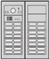 | 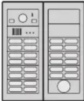 | 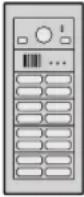 | 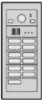 | |
| Model no. Number of call buttons (Unit: pcs.) | 32 28 16 13 | ||||
| VL-VM101 Camera module 1 1 1 1 | |||||
| VL-VM301 1-button module --- 1 | |||||
| VL-VM302 2-button module --- | |||||
| VL-VM303 3-button module --- | |||||
| VL-VM304 4-button module 8 7 4 3 | |||||
| VL-VM901 Blank panel 2 2 --- | |||||
| VL-VM801 Extension cable 1 1 --- | |||||
| VL-VM603 Back box 2 2 1 1 | |||||
| VL-VM503^*1 | Surface mount cover*1 | 2 2 1 1 | |||
| VL-VM902 | VIGIK® panel*2 | -1-- | |||
Small type lobby station example
| Module | 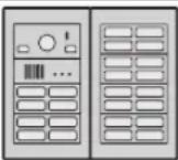 | 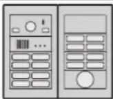 | 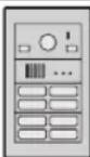 | 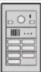 | 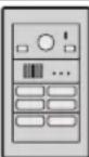 | |
| Model no. Number of room buttons (Unit: pcs.) | 24 16 | 8 | 7 | 6 | ||
| VL-VM101 | Camera module | 1 | 1 | 1 | 1 | 1 |
| VL-VM301 | 1-button module | - | - | - | - | - |
| VL-VM302 | 2-button module | - | - | - | - | 1 |
| VL-VM303 | 3-button module | - | - | - | 1 | - |
| VL-VM304 | 4-button module | 6 | 4 | 2 | 1 | 1 |
| VL-VM901 | Blank panel | - | 1 | - | - | - |
| VL-VM801 | Extension cable | 1 | 1 | - | - | - |
| VL-VM602 | Back box | 2 | 2 | 1 | 1 | 1 |
| VL-VM502^*1 | Surface mount cover*1 | 2 | 2 | 1 | 1 | 1 |
| VL-VM902 | VIGIK panel*2 | - | 1 | - | - | - |
*1 The surface mount cover cannot be attached when the lobby station is flush mounted. However, make sure to use the surface mount cover when the lobby station is surface mounted.
*2 For France
2.1 Important safety information
To prevent severe injury or loss of life or property, and to ensure proper and safe operation of your product, read this section carefully before using the product.

WARNING
Preventing fire, electric shock and short circuits
- Leave installation work to the dealer. Installation work requires technical knowledge and experience. Electrical connection work should be performed by certified personnel only. Failure to observe this may cause fire, electric shock, injury, or damage to the product. Consult the dealer.
• For Australia/New Zealand only:
VL-PS240 or VL-PS2410 only: Installation must only be by a registered electrician. Wiring must be performed according to AS/NZS 3000 wiring rules. - Use only the power supply unit VL-PS240 or VL-PS2410.
- Do not place objects on the power cables. Install the product where no one can step or trip on the power cables.
- Do not allow the power cables to be excessively pulled, bent or placed under heavy objects.
- Make sure all connections from the power outlet to the power supply unit are secure.
- Never touch the power supply unit and power cables with wet hands.
- Do not use the power supply unit for outdoor installations (it is for indoor use only).
- Do not disassemble or modify the product. Refer servicing to an authorised service centre when service is required. Disassembling the product or manipulating the product in a way not described in the documentation may expose you to dangerous voltages and other risks.
- Do not touch the product or the power supply unit during an electrical storm. There may be a remote risk of electric shock from lightning.
- Never install wiring during a lightning storm.
- Do not connect non-specified devices.
- Do not connect a power cable to a terminal that is not specified in this document.
- When opening holes in walls for installation or wiring, or when securing the power cable, make sure you do not damage existing wiring and ductwork.
- Do not make any wiring connections when the power outlet is turned on.
- Do not install the product and power supply unit in the following places:
- Places where the product and power supply unit may be splashed with water or chemicals
-
Places where there is a high concentration of dust or high humidity
-
Do not push any objects through the openings of the product.
- If any of the following conditions occur, disconnect the power supply unit from the power outlet, and then refer servicing to an authorised service centre.
– The product emits smoke, an abnormal smell or makes unusual noise
– The power cables are damaged or frayed
– Metal objects have been dropped inside the product - When existing wires are used, it is possible that they contain AC voltage. Contact an authorised service centre.
Preventing accidents
- Name plate buttons may become a choking hazard. Keep name plate buttons out of reach of children. If you suspect a child has swallowed a name plate button, seek medical advice immediately.

CAUTION
Preventing accidents, injuries, and property damage
- Do not use the product in unstable areas or areas prone to strong vibrations. This may cause the product to fall, resulting in damage to the product or injury.
- Make sure you turn off the power at the breaker before performing any wiring work.
- Always connect power cables to the appropriate connection terminals. Incorrectly connecting the power cables may damage the power supply unit.
- To prevent the power cables from disconnecting and to prevent electric shock, secure the power cable using the included cable binders and attach the cable covers.
- Insert the power cables firmly all the way into the terminals. If the cables are not inserted all the way, heat may be generated.
- If the wiring passes outdoors, use a conduit and a surge protector.
- If the wiring passes underground, use a conduit, and do not make any connections underground.
- Install the product securely adhering to the instructions in this document to prevent it from falling off the wall. Avoid installing onto low-strength walls, such as gypsum board, ALC (autoclaved lightweight concrete), concrete block, or veneer (less than 18 mm thick) walls.
- The power supply unit is used as the main disconnect device. Ensure that the power outlet is installed near the product and is easily accessible.
- Do not put your ear(s) near the speaker, as loud sounds emitted from the speaker may cause hearing impairment.
2.2 Important safety instructions
When using this product, basic safety precautions should always be followed to reduce the risk of fire, electric shock, or personal injury.
Use only the power supply unit indicated in this document.
SAVE THESE INSTRUCTIONS
2.3 Privacy and rights of portrait
When installing or using the product, please take into consideration the rights of others with regard to privacy.
- It is generally said that "privacy" means the ability of an individual or group to stop information about themselves from becoming known to people other than those whom they choose to give the information. "Rights of portrait" means the right to be safe from having your own image taken and used indiscriminately without consent.
- Please observe the legal regulations (data protection, video surveillance) in your country during use.
2.4 Disclaimer
- To the maximum extent permitted by law, Panasonic assumes no responsibility for injuries or property damage resulting from failures arising out of improper installation or operation inconsistent with this document.
2.5 Other important information
- When you leave the product unused for a long period of time, unplug it from the power outlet.
- If you stop using the product, remove it from the walls to prevent it from falling off.
- When power fails, this product cannot be used.
- Panasonic may not be liable for damages due to external factors such as power failures.
2.6 General information
- The available products differ depending on your region. For more information, please consult your dealer.
- In the event of problems, you should contact your equipment supplier in the first instance.
- After removing the product and any included items from the packaging, store, dispose, or recycle the packaging as necessary. Note that certain types of packaging may be a suffocation or choking hazard.
Graphical symbols for use on equipment and their descriptions
| Symbol Explanation | |
| ~ | Alternating current (A.C.) |
| --- | Direct current (D.C.) |
| Protective earth | |
| Protective bonding earth | |
| Functional earth | |
| For indoor use only | |
| Class II equipment (equipment in which protection against electric shock relies on Double Insulation or Reinforced Insulation) | |
| "ON" (power) | |
| "OFF" (power) | |
| Stand-by (power) | |
| "ON"/"OFF" (power; push-push) | |
| Caution, risk of electric shock | |
Disposal of Old Equipment (Only for European Union and countries with recycling systems)
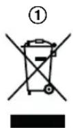
This symbol (①) on the products, packaging, and/or accompanying documents means that used electrical and electronic products must not be mixed with general household waste.
For proper treatment, recovery and recycling of old products, please take them to applicable collection points in accordance with your national legislation. By disposing of them correctly, you will help to save valuable resources and prevent any potential negative effects on human health and the environment.
For more information about collection and recycling, please contact your local municipality.
Penalties may be applicable for incorrect disposal of this waste, in accordance with national legislation.
For business users in the European Union
If you wish to discard electrical and electronic equipment, please contact your dealer or supplier for further information.
Information on Disposal in other Countries outside the European Union
This symbol (①) is only valid in the European Union. If you wish to discard this product, please contact your local authorities or dealer and ask for the correct method of disposal.
2.7 For India only
Declaration of Conformity with the requirements of the E-Waste (Management) Rules
The Product is in conformity with the requirements of the reduction of hazardous substances of the E-Waste Rules.
The content of hazardous substance with the exemption of the applications listed in SCHEDULE II of the E-Waste Rules:
- Lead (Pb) – not over 0.1% by weight;
- Cadmium (Cd) – not over 0.01% by weight;
- Mercury (Hg) – not over 0.1% by weight;
- Hexavalent chromium (Cr6+) – not over 0.1% by weight;
- Polybrominated biphenyls (PBBs) – not over 0.1% by weight;
- Polybrominated diphenyl ethers (PBDEs) – not over 0.1% by weight.
Disposal information
For the purpose of recycling to facilitate effective utilization of resources, please return this product to a nearby authorized collection centre, registered dismantler or recycler, or Panasonic service centre when disposing of this product.
Please see the Panasonic website for further information on collection centres, etc., or call the toll-free number below.
Website:
http://www.panasonic.com/in/corporate/sustainability/panasonic-india-i-recycle-program.html
Service helpline: 1800 103 1333 or 1800 108 1333
2.8 For Europe
For information of Compliance with EU relevant Regulatory Directives,
Contact to Authorised Representative:
Panasonic Testing Centre
Panasonic Marketing Europe GmbH
Winsbergring 15, 22525 Hamburg, Germany
http://www.ptc.panasonic.eu/doc
Ecodesign information
Ecodesign information under EU Regulation (EC)
No. 1275/2008 amended by (EU) Regulation
No. 801/2013. From 1 January 2015.
Please visit here:
http://www.ptc.panasonic.eu/erp
Click [Downloads] → [Energy related products information (Public)]
Power consumption in networked standby and guidance are mentioned in the web site above.
This device is classified as a HiNA device (networked equipment with high network availability), according to Ecodesign requirements.
3.1 System devices
The following modules or devices are sold separately. Please contact your nearest Panasonic dealer for sales information.
Compatible system devices (as of July 2018)
3.1.1 Lobby station
The lobby station is composed of combinations of modules. The following items are included with the modules.
VL-VM101
| Item Quantity | |
Camera module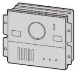 | 1 |
Flat cableUsed to connect modules. | 1 |
3-pin terminal blockUsed to connect wires to the K-OUT connection terminals.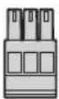 | 1 |
6-pin terminal blockUsed to connect wires to the K-IN (4 pins) and connection terminals when using bus wiring (2 pins).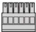 | 1 |
| DC terminal blockUsed to connect wires from the power supply unit to the lobby station.[ZXT6] | 1 |
VL-VM301
| Item Quantity | |
1-button module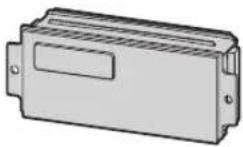 | 1 |
Flat cableUsed to connect modules.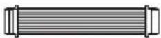 | 1 |
2-pin terminal blockUsed when using star wiring.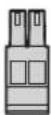 | 1 |
Spare buttonUsed as a spare when replacing name plates. | 1 |
Name sheetUsed as a spare when replacing name plates.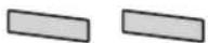 | 2 |
Screw (2 mm × 3 mm)Used to prevent the removal of name plates.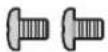 | 2 |
VL-VM302
| Item Quantity | |
2-button module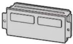 | 1 |
Flat cableUsed to connect modules.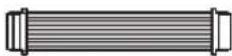 | 1 |
2-pin terminal blockUsed when using star wiring.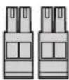 | 2 |
Spare buttonUsed as a spare when replacing name plates. | 1 |
Name sheetUsed as a spare when replacing name plates.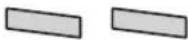 | 2 |
Screw (2 mm × 3 mm)Used to prevent the removal of name plates.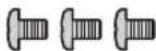 | 3 |
VL-VM303
| Item Quantity | |
3-button module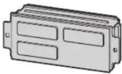 | 1 |
Flat cableUsed to connect modules.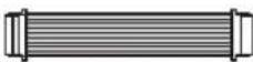 | 1 |
2-pin terminal blockUsed when using star wiring.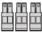 | 3 |
Spare buttonUsed as a spare when replacing name plates.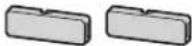 | 2 |
| Name sheetUsed as a spare when replacing name plates. | 4 |
Screw (2 mm × 3 mm)Used to prevent the removal of name plates.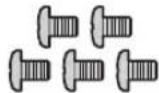 | 5 |
3. Preparation
VL-VM304
| Item Quantity | |
4-button module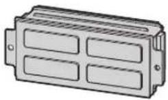 | 1 |
Flat cableUsed to connect modules.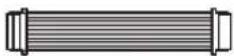 | 1 |
2-pin terminal blockUsed when using star wiring.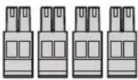 | 4 |
Spare buttonUsed to prevent the removal of name plates.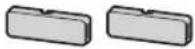 | 2 |
| Name sheetUsed as a spare when replacing name plates. | 4 |
| Screw (2 mm × 3 mm)Used to prevent the removal of name plates. | 6 |
VL-VM901
| Item Quantity | |
Blank panel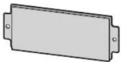 | 1 |
VL-VM801
| Item Quantity | |
Extension cableUsed to connect 2 frames of a lobby station together.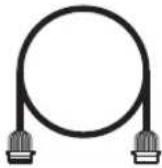 | 1 |
VL-VM902 (for France)
| Item Quantity | |
VIGIK panel 1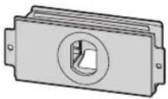 | |
| Waterproof rubber*1Used when attaching the VIGIK reader. | 1 |
*1 The waterproof rubber is fixed to the panel with tape. Remove the waterproof rubber when attaching the panel.
VL-VM602 (small type)
| Item Quantity | |
Back box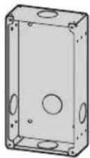 | 1 |
FrameUsed to assemble modules.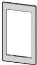 | 1 |
Side plateUsed to secure and attach the left and right sides of modules.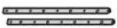 | 2 |
Screw (3 mm × 5 mm)Used to attach modules to side plates.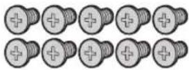 | 10 |
Upper/lower plateUsed to attach the back box to a wall.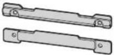 | 2 |
Screw (4 mm × 25 mm)Used to secure the upper and lower plates.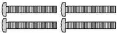 | 4 |
Hexalobular screw(3 mm × 12 mm)Used to secure the lobby station to the back box. | 1 |
Hexalobular wrench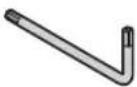 | 1 |
VL-VM603 (large type)
| Item Quantity | |
| Back box | 1 |
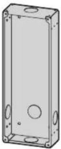 |
| Item Quantity | |
FrameUsed to assemble modules.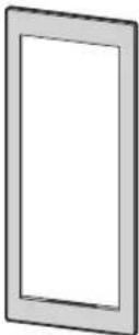 | 1 |
| Side plateUsed to secure and attach the left and right sides of modules. | 2 |
Screw (3 mm × 5 mm)Used to attach modules to side plates.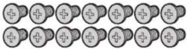 | 14 |
Upper/lower plateUsed to attach the back box to a wall.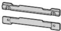 | 2 |
Screw (4 mm × 25 mm)Used to secure the upper and lower plates.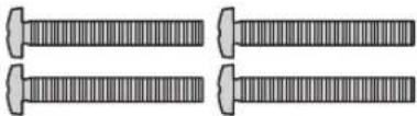 | 4 |
Hexalobular screw(3 mm × 12 mm)Used to secure the lobby station to the back box. | 1 |
Hexalobular wrench 1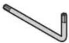 |
3. Preparation
VL-VM502 (small type)
| Item Quantity | |
Surface mount cover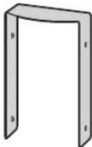 | 1 |
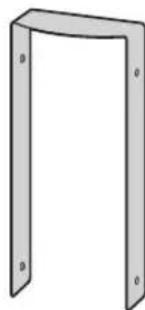
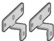
BracketUsed to attach the surface mount cover to the back box.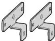 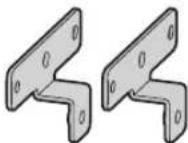 | 4 |
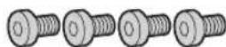
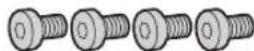
Hex screw (3 mm × 5 mm)Used to attach the bracket to the back box.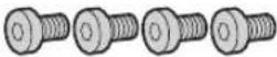 Used to attach the surface mount cover to the bracket. Used to attach the surface mount cover to the bracket. | 8 |
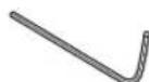
Hex wrench 1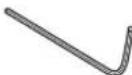 | |
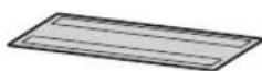
Dustproof sheetUsed to attach the sheet to the bottom of the back box.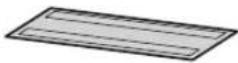 | 1 |
natural_image
Simple 3D diagram of a rectangular frame with corner markers (no text or symbols)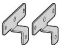
3.1.2 Distributor
| Item Quantity | |
Distributor 1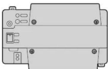 | |
| Screw (3.8 mm × 20 mm)Used to secure the distributor to the wall. | 2 |
| Cable binderUsed to secure the connected wires. | 2 |
3.1.3 Power supply unit
VL-PS240 (0.6 A type)
| Item Quantity | |
Power supply unit 1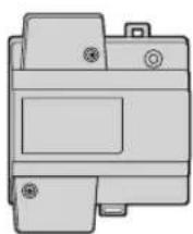 | |
| Screw (4 mm × 40 mm)Used to secure the power supply unit to the wall. | 2 |
| Cable binderUsed to secure the AC and DC wires. | 2 |
VL-PS2410 (2.5 A type)
| Item Quantity | |
Power supply unit 1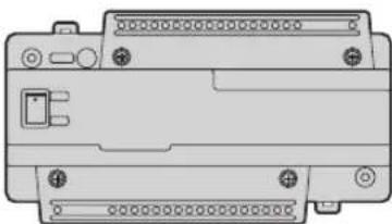 | |
| Screw (3.8 mm × 20 mm)Used to secure the power supply unit to the wall.[IMAGE] | 2 |
Cable binderUsed to secure the AC and DC wires. | 2 |
3.2 Device diagrams
3.2.1 Lobby station
Front view
Example: 12 call buttons on lobby station
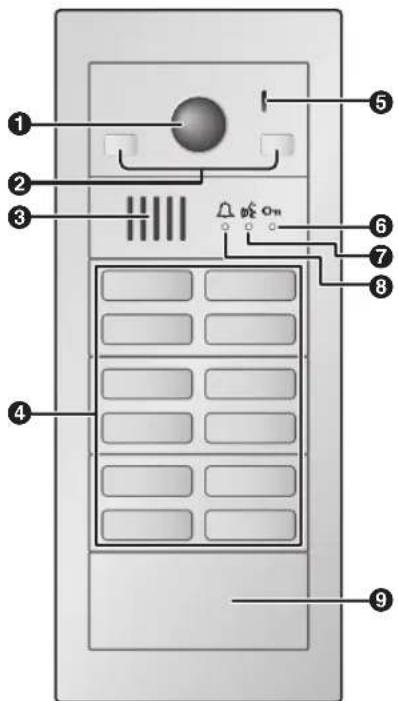
Rear view
Example: lobby station with terminal cover removed
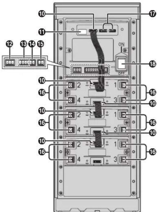
① Lens cover
② Light
③ Speaker
④ Call buttons
Illuminates in dark environments depending on the DIP switch settings (page 40).
⑤ Microphone
⑥ Unlock indicator (Oπ; blue)
⑦ Talk indicator (amber)
⑧ Call indicator (red)
⑨ Blank panel
10 Flat cable connector
Used to connect modules together.
⑪ DIP switches
See page 40.
⑫ K-OUT connection terminals (output)
Used to send signal to an electric lock.
⑬ K-IN connection terminals (input)
Used to receive signals from an access controller and/or open door sensor, etc.
14 Line connection terminals for bus wiring
Used to connect to distributors or extension boxes when using bus wiring.
⑮ DC IN connection terminals for power supply
Used to connect the lobby station to the power supply unit.
16 Line connection terminals for star wiring
Used to connect to main monitors when using star wiring.
⑰ For internal use only
18 Power switch
3.2.2 Distributor
Example: distributor with the cable cover removed
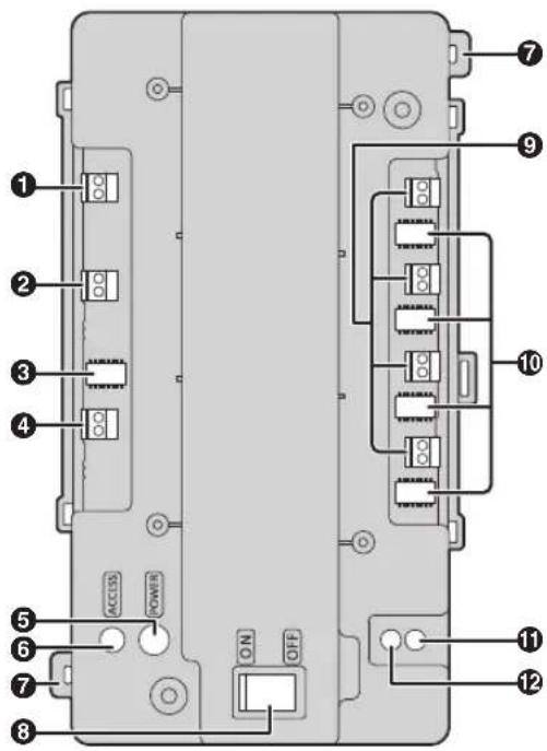
① Connection terminals (output) for next distributor
② Connection terminals (input) for lobby station, extension box or previous distributor
③ DIP switches for distributor ID setting
See page 41.
4 DC IN connection terminals for power supply
Used to connect the distributor to the power supply unit.
⑤ POWER indicator
See page 43.
⑥ ACCESS indicator
See page 43.
⑦ Hook for tying cables to with a cable binder
⑧ Power switch
⑨ Connection terminals for main monitors
⑩ DIP switches for room number ID setting
See page 42.
11 Function button (●●)
For internal use only.
⑫ Reset button (•)
Used when restarting the distributor.
3.3 Specifications
Whole system capacity
- Lobby station (VL-VM series):
Star wiring: up to 1
Bus wiring: up to 6
- Main monitor ^1 (VL-MV10, VL-MWD501, VL-MVN511, VL-MWD272, VL-MWD273, VL-MV71, VL-MV72): up to 32 ^2
• Distributor (VL-VM701): up to 8*3 - Extension box (VL-V703): up to 1^*4
Lobby station (VL-VM series; sold separately)
| Power source Power supply unitVL-PS240: 24 V DC, 0.6 AorVL-PS2410: 24 V DC, 2.5 A | |
| Power consumption | VL-VM101Standby: 1.8 WOperating: 9.9 WMeasurement conditions:- Lobby station consists of VL-VM101 (1 pcs.) and VL-VM301 (1 pcs.).- VL-MV10 (1 pcs.) is connected to the lobby station.- VL-PS240 is used as the power supply unit. |
| Dimensions (mm) (height × width × depth) *10 (excluding protruding sections) | Flush mount (small type): approx. 226 × 130 × 9^*5 , *6Flush mount (large type): approx. 315 × 130 × 9^*5 , *7Surface mount (small type): approx. 233 × 135 × 89^*8 Surface mount (large type): approx. 322 × 135 × 89^*9 |
| Mass (weight) *10 | Flush mount (small type): approx. under 1.3 kg^*6 Flush mount (large type): approx. under 1.8 kg^*7 Surface mount (small type): approx. under 1.7 kg^*8 Surface mount (large type): approx. under 2.2 kg^*9 |
| Operating environment | Ambient temperature: approx. -15 °C to +55 °CRelative humidity (non-condensing): up to 90 % |
| Installation method | Flush mount (using the back box; sold separately)Surface mount (using the back box and surface mount cover; sold separately) |
| External material | Stainless steel (surface mount cover)Aluminum (partially PC and ABS) |
| Talking method Hands-free | |
| Image sensor 1/4 inch CMOS sensor (approx. 1M pixels) | |
| Viewing angle Horizontally: approx. 170°Vertically: approx. 110° | |
| Minimum illuminance required | 1 lx (within approx. 50 cm from the camera lens) |
| Lighting method White coloured LED lights | |
| IP rating | IP55*11, *12 |
| IK rating | Compliant with IK08*12 |
| Audio guidance languages (when unlocking a door) | English/German/French/Italian/Spanish/Dutch/Arabic/Persian |
| HAC (Hearing Aid Compatibility) | Not Compatible |
*1 The available products differ depending on your region. For more information, please consult your dealer.
*2 Depending on the composition of the lobby station's modules.
*3 Required when using bus wiring.
*4 Required when expanding the lobby stations with bus wiring.
*5 Excluding sections embedded into the wall.
*6 Includes (VL-VM101 x 1 pcs.) + (VL-VM304 x 2 pcs.) + VL-VM602 (small type)
*7 Includes (VL-VM101 x 1 pcs.) + (VL-VM304 x 4 pcs.) + VL-VM603 (large type)
*8 Includes (VL-VM101 x 1 pcs.) + (VL-VM304 x 2 pcs.) + VL-VM602 + VL-VM502 (small type)
*9 Includes (VL-VM101 x 1 pcs.) + (VL-VM304 x 4 pcs.) + VL-VM603 + VL-VM503 (large type)
*10 For France: Does not include the dimensions and weight of the VIGIK.
*11 Water resistance is only assured if the product is installed correctly according to the instructions, and appropriate water protection measures are taken.
*12 When a VIGIK module is installed, the rating does not include the VIGIK module.
Distributor (VL-VM701; sold separately)
The distributor is for indoor use only.
| Power source Power supply unitVL-PS240: 24 V DC, 0.6 AorVL-PS2410: 24 V DC, 2.5 A | |
| Power consumption | Standby: 1.6 WOperating: 9.0 WMeasurement conditions:- Consumption for 1 VL-VM701 device when other VL-VM701 devices are not supplying power.- VL-MV10 (1 pcs.) is connected to VL-VM701.- VL-PS240 is used as the power supply unit. |
| Dimensions (mm) (height × width × depth) (excluding protruding sections) | Approx. 133 x 210 x 51 |
| Mass (weight) Approx. 440 g | |
| Operating environment | Ambient temperature: approx. -10 °C to +55 °CRelative humidity (non-condensing): up to 90 % |
| Installation method | Attach to DIN railWall mount (using included screws) |
| External material | ABS (flame retardant ABS resin) |
Power supply unit (VL-PS240; sold separately)
The power supply unit is for indoor use only.
| Power source Input: 220–240 V AC, 0.2 A,50/60 HzOutput: 24 V DC, 0.6 A | |
| Dimensions(mm) (height ×width × depth)(excluding protruding sections) | Approx. 116 × 100 × 54 |
| Mass (weight) Approx. 230 g | |
| Operating environment | Ambient temperature: approx.0 °C to +50 °CRelative humidity(non-condensing): up to 90 % |
| Installation method | Attach to DIN railWall mount (using included screws) |
| External material | Flame retardant PC+ABS resin |
Power supply unit (VL-PS2410; sold separately)
The power supply unit is for indoor use only.
| Power source Input: 220–240 V AC, 1 A,50/60 HzOutput: 24 V DC, 2.5 A | |
| Dimensions(mm) (height ×width × depth)(excluding protruding sections) | Approx. 116 × 210 × 58 |
| Mass (weight) Approx. 530 g | |
| Operating environment | Ambient temperature: approx.0 °C to +50 °CRelative humidity(non-condensing): up to 90 % |
| Installation method | Attach to DIN railWall mount (using included screws) |
| External material | Flame retardant PC+ABS resin |
4.1 Installation cautions
Refer to the information found in 2 Important Information (page 7) before installing the product.

CAUTION
- Always connect power cables to the appropriate connection terminals. Incorrectly connecting the power cables may damage the power supply unit.
- To prevent the power cables from disconnecting and to prevent electric shock, secure the power cables using the included cable binders and attach the cable covers.
- If the wiring passes outdoors, use a conduit and a surge protector.
- If the wiring passes underground, use a conduit, and do not make any connections underground.
- Install the product securely adhering to the instructions in this document to prevent it from falling off the wall. Avoid installing onto low-strength walls, such as gypsum board, ALC (autoclaved lightweight concrete), concrete block, or veneer (less than 18 mm thick) walls.
4.2 Installing the power supply unit (sold separately)
Required items
– Power supply unit (VL-PS240 or VL-PS2410; sold separately)
– Cable binders (included with power supply unit)
– Screws (included with power supply unit)
- Wires for AC and DC connection (user supplied) See "4.6.2 Wire type and maximum wire length (Page 39)".
Installation location
- The device must be installed inside an electrical panel or cabinet.
- A readily accessible disconnect device shall be incorporated external to the equipment.
The external disconnect device must be certified, and have a creepage and clearance distance of 3 mm or more.
Installation methods
The following 2 methods can be used for installing the power supply unit.
– mounting on a DIN rail (user supplied)
- attaching directly to a wall
4.2.1 Connecting the AC wires and DC wires (VL-PS240)
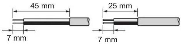
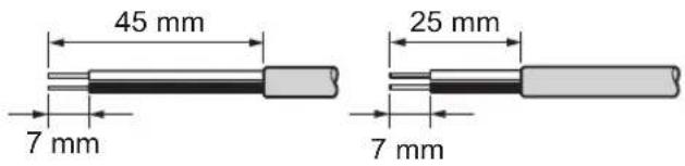
1 Strip the ends of the wires that connect to the power supply unit as shown below.
AC wires DC wires
2 Remove the cable cover screws and then remove the cable covers.
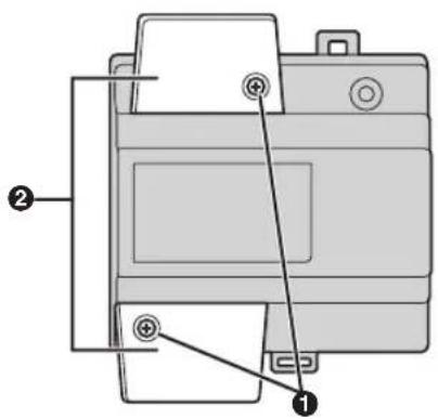
① Screws
② Cable covers
3 Connect the AC wires to the AC IN terminals on the top of the power supply unit, and then connect the DC wires to the DC OUT terminals on the bottom of the power supply unit.
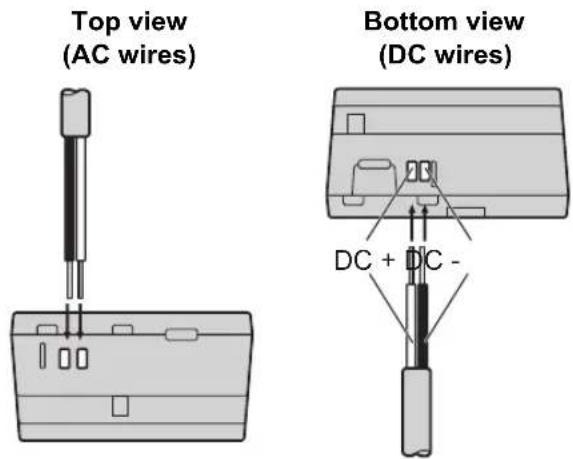
- For DC wires, the black wire is negative (-) and the other colour wire is positive (+). Note the colour of each DC wire and which terminal each
wire should be connected to, and insert the DC wires as shown.

CAUTION
- Insert the power cables firmly all the way into the terminals. If the cables are not inserted all the way, heat may be generated.
4 Tighten the terminal screws to secure the AC and DC wires (bare wire area) to the terminals, and then use the cable binders to secure the AC and DC wires (jacketed area) to the cable binder holes on the top and bottom on the power supply unit.
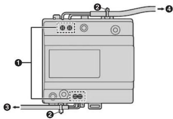
① Terminal screws
② Cable binders connected to cable binder holes
③ To lobby station
④ To AC power outlet
- Recommended torque:
- AC IN terminals: 0.5 N·m {5.1 kgf·cm}
- DC IN terminals: 0.45 N·m {4.6 kgf·cm}
5 Make sure to reattach the cable covers and then securely fasten the cable cover screws.
4.2.2 Connecting the AC wires and DC wires (VL-PS2410)
1 Strip the ends of the wires that connect to the power supply unit as shown below.
AC wires DC wires
2 Remove the cable cover screws and then remove the cable covers.
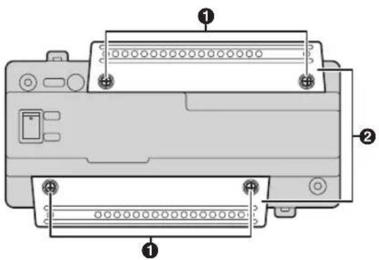
① Screws
② Cable covers
3 Connect the AC wires to the AC IN terminals on the top of the power supply unit, and then connect the DC wires to the DC OUT terminals on the bottom of the power supply unit.
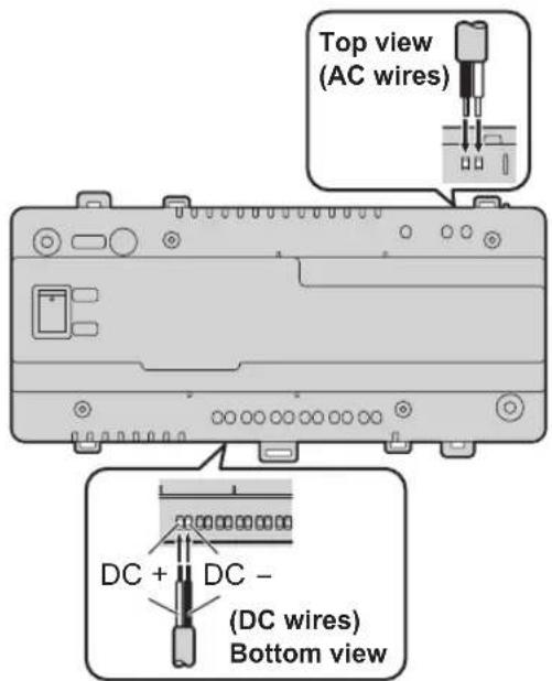
- For DC wires, the black wire is negative (-) and the other colour wire is positive (+). Note the colour of each DC wire and which terminal each
wire should be connected to, and insert the DC wires as shown.

CAUTION
- Insert the power cables firmly all the way into the terminals. If the cables are not inserted all the way, heat may be generated.
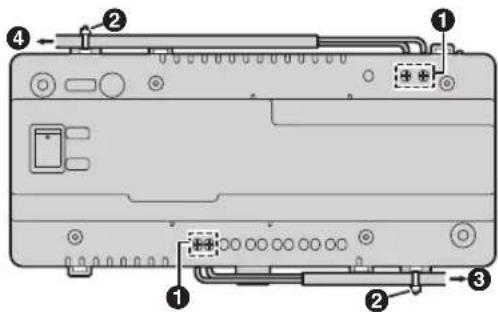
4 Tighten the terminal screws to secure the AC and DC wires (bare wire area) to the terminals, and then use the cable binders to secure the AC and DC wires (jacketed area) to the cable binder holes on the top and bottom on the power supply unit.
Example: DC terminal 1 is used.
Example: DC terminal 1-6 are used.
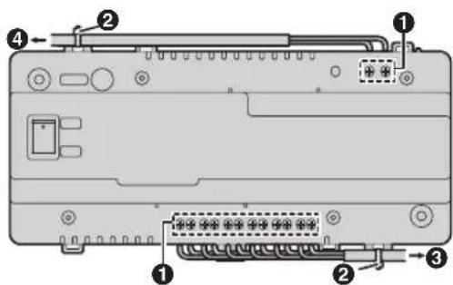
① Terminal screws
② Cable binders connected to cable binder holes
③ To lobby station or distributor
④ To AC power outlet
- Recommended torque:
- AC IN terminals: 0.5 N·m {5.1 kgf·cm}
- DC IN terminals: 0.45 N·m {4.6 kgf·cm}
5 Make sure to reattach the cable covers and then securely fasten the cable cover screws.
- After reattaching the cable covers, attach the cable to the cable hook.
6 After connecting wires to each device, turn the output switch on.
- The OUTPUT indicator lights when the output switch is turned on.
4.2.3 Information about the power supply unit
After connecting the power supply units, make connections to each device.
Note:
- The VL-PS2410 power supply unit has 6 DC OUT connection terminals. (Use the VL-PS2410 so that the combined output does not exceed 2.5 A. Check the power consumption of each device for more information.)
- Other than for VL-MV10 bus-powered main monitors, use the power supply units included with the main monitors or connect the power cord of the main monitors.
- VL-MV10 bus-powered main monitors receive power from a lobby station (when using star wiring) or a distributor (when using bus wiring), and therefore do not need a power supply unit. When using VL-MV10, we recommend using a VL-PS2410.
Power supply for distributors and wiring for power supply units
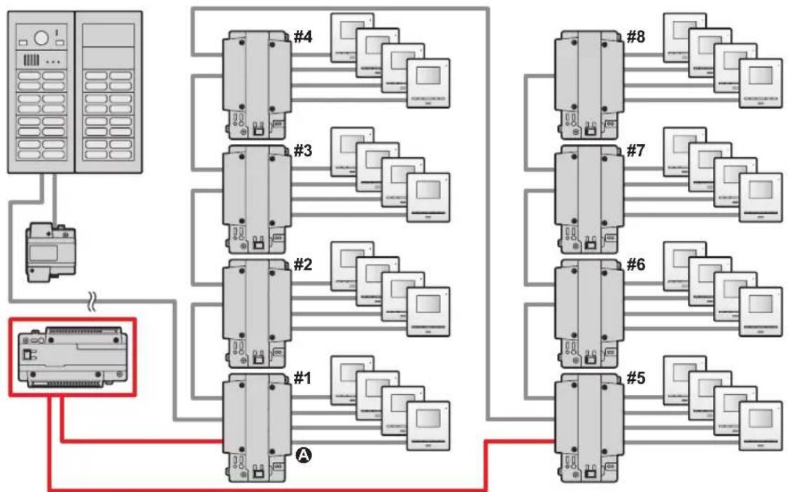
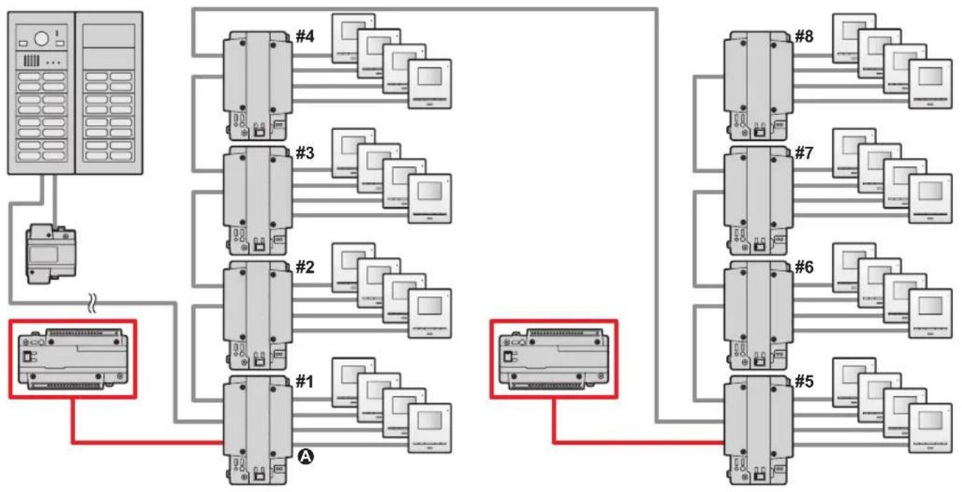
In order to start up distributors (A); maximum of 8) that use bus wiring, use either the VL-PS240 or VL-PS2410 power supply units in one of the following arrangements.
■ Number of operable VL-VM701 (distributors)
| Number of connectable distributors | |||
| With VL-MV10 main monitor With other main monitors | |||
| Power supply unit | VL-PS240 (0.6 A type) | Up to 1 distributor (VL-PS240 can only be used in systems with 1 distributor) | Up to 4 distributors (for each power supply unit) ^*1 |
| VL-PS2410 (2.5 A type) ^*1 | Up to 8 distributors (for each power supply unit) | Up to 8 distributors (for each power supply unit) | |
*1 Connection when using 1 power supply unit: 1st distributor
Connection when using 2 power supply units: 1st distributor and 5th distributor
Example: when a VL-MV10 is connected using 1 VL-PS2410 power supply unit
If the system consists of 1 VL-PS2410 and 5 or more distributors are used, connect wiring from the VL-PS2410 to the 1st and 5th distributors.
flowchart
graph TD
    A["Server"] --> B["Client"]
    B --> C["Client 1"]
    B --> D["Client 2"]
    B --> E["Client 3"]
    B --> F["Client 4"]
    C --> G["Client 5"]
    D --> H["Client 6"]
    E --> I["Client 7"]
    F --> J["Client 8"]
    G --> K["Computer 1"]
    H --> L["Computer 2"]
    I --> M["Computer 3"]
    J --> N["Computer 4"]
    style A fill:#f9f,stroke:#333
    style B fill:#ccf,stroke:#333
    style C fill:#cfc,stroke:#333
    style D fill:#cfc,stroke:#333
    style E fill:#cfc,stroke:#333
    style F fill:#cfc,stroke:#333
    style G fill:#fcc,stroke:#333
    style H fill:#fcc,stroke:#333
    style I fill:#fcc,stroke:#333
    style J fill:#fcc,stroke:#333
    style K fill:#cff,stroke:#333
    style L fill:#cff,stroke:#333
    style M fill:#cff,stroke:#333
Example: when a VL-MV10 is connected using 2 VL-PS2410 power supply units
The system consists of 2 VL-PS2410 power supply units.
flowchart
graph TD
    A["Server"] --> B["PLC1"]
    A --> C["PLC2"]
    A --> D["PLC3"]
    A --> E["PLC4"]
    B --> F["Computer 1"]
    B --> G["Computer 2"]
    B --> H["Computer 3"]
    C --> I["Computer 4"]
    C --> J["Computer 5"]
    C --> K["Computer 6"]
    D --> L["Computer 7"]
    D --> M["Computer 8"]
    E --> N["Computer 9"]
    E --> O["Computer 10"]
    F --> P["Red Box 1"]
    G --> P
    H --> P
    I --> P
    J --> P
    K --> P
    L --> P
    M --> P
    N --> P
    O --> P
    P --> Q["Red Box 2"]
    Q --> R["Computer 11"]
    Q --> S["Computer 12"]
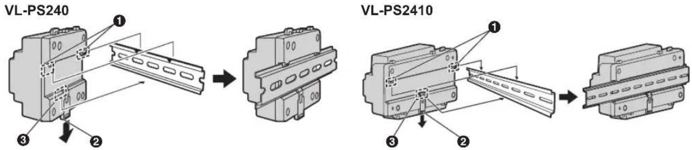
4.2.4 Mounting on a DIN rail
Attach the power supply unit to the DIN rail so that the bottom hook is positioned at the bottom of the power supply unit.
1 Hang the top hooks (①) of the power supply unit on the top of the DIN rail.
- At this point the power supply unit will be hanging from the DIN rail but will not be secure.
2 Pull the lever (②) down, make sure the bottom of the power supply unit is flat against the DIN rail, and then release to lever.
- The bottom hook (③) will slide up, securing the bottom of the power supply unit to the DIN rail.
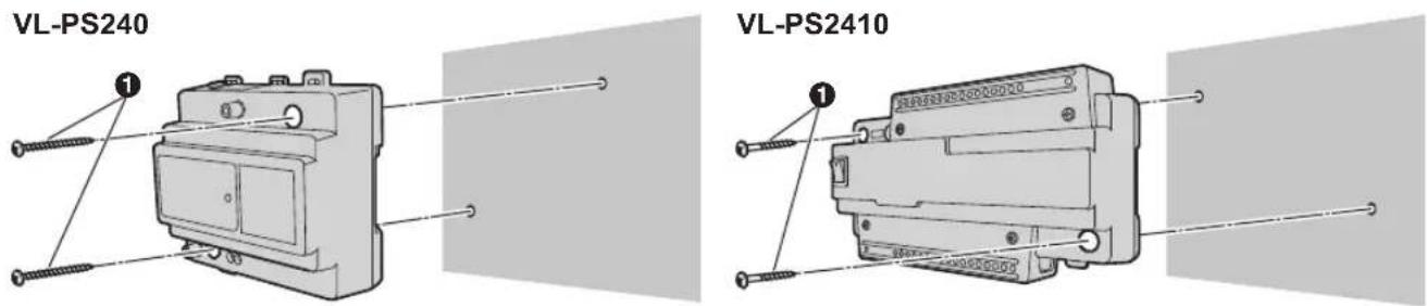
4.2.5 Attaching directly to a wall
Attach the power supply unit to the wall securely using the 2 mounting screws (1).
4.3 Installing the lobby station
Required items
- Module parts kit (sold separately) with lobby station assembly
- Back box parts kit (sold separately)
- Surface mount cover parts kit (sold separately) *1
- Extension cable (sold separately) used to connect 2 frames of a lobby station together
- Wires that connect the lobby station to the electric lock, and K-IN connection device (example: access controller and/or open door sensor, etc.)
See "4.6.2 Wire type and maximum wire length (Page 39)".
*1 A surface mount cover is required when the lobby station is surface mounted.
Installation location
- Do not install the product in the following locations. There may be a risk of malfunction or communication disturbances.
- Places where vibration, impact, or echoing occurs.
- Places near a high concentration of dust, hydrogen sulphide, ammonia, sulphur, or noxious fumes.
- Places where there is excessive smoke, dust, and high temperature.
– Places exposed to direct sunlight.
- Places where most of the background is the sky.
- Places where the background is a white wall, and direct sunlight will reflect off it.
- Near ocean coasts, where sea breezes will contact the product directly, or near sulphuric hot springs (exposure to salt can reduce the product's life expectancy).
- Install the product away from electronic appliances such as TVs, radios, personal computers, air conditioners, boiler control panels with intercom, home security equipment, wireless devices, or digital cordless phones.
- Dust protection/water protection is IP55. Only when installation work specified in this document is properly performed and appropriate water protection treatment is performed.
- Make sure the rear of the product is not subject to water.
- Depending on the installation location, condensation may form on the product's lens cover. This may cause images to become obscured. Condensation will dissipate as the temperature rises.
4.3.1 Installation position of the lobby station and camera range
Refer to the following examples and confirm the area viewable by the camera. In each illustration, the viewable area is indicated by "①" and the centre of the camera lens is indicated by "②".
Side view
Camera height: 1500 mm
Camera lens angle: 0°
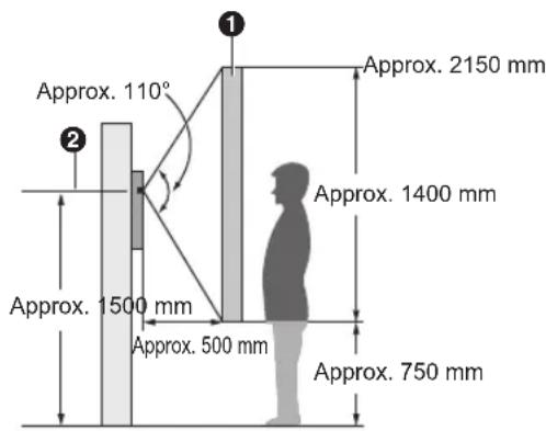
Top view
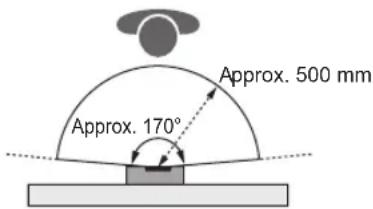
Note:
- The measurements and angles shown here are for reference purposes and may vary depending on the environment.
- Install the lobby station so that the lobby station is not exposed to strong light. If strong light shines on the lobby station, the visitor's face may not be distinguishable.
4.3.2 Assembling lobby station modules
The lobby station is composed of a combination of modules according to the number of rooms connected to.
- See page 6 for information on the composition of each module.
- See page 10 for information on the items included with each module.
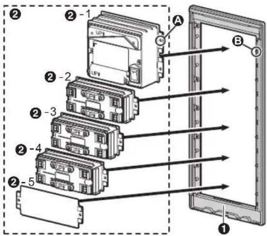
Example: lobby station for camera module × 1 pcs. + button module × 3 pcs. + blank panel × 1 pcs.
1 Attach each module (②) to the frame (①) as shown below.
- Starting from the camera module, attach each module in order from the top. (2-1—2-5)
- Insert the holders (A) into the slots (B) on the both sides of the frame.
- The combination of modules changes according to the number of rooms connected to.
2 Hold down the left and right side plates (③), secure them using the screws (④). Make sure that each module is securely attached.
- The included number of screws differs according to the back box type (large or small) connected to.
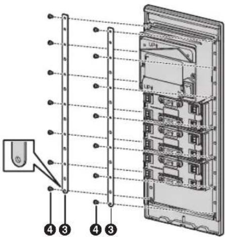
4.3.3 Connecting flat cables
1 Remove each terminal cover (①) from each module (①-1).
- Remove the terminal cover of the attached module.
2 Connect the flat cable (②) from the camera module to the module of the next button.
- Starting from the camera module, attach each module in order from the top.
3 Connect the flat cables (②) to all of the remaining modules.
4 After connections are completed, reattach each terminal cover (①) to each terminal (①-2). Make sure each module is securely attached.
• ③: 1 of the included flat cables will not be used
Example: lobby station for camera module × 1 pcs. + button module × 3 pcs. + blank panel × 1 pcs.
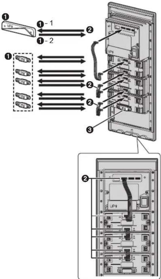
4.3.4 Connecting 2 frames of a lobby station using the extension cable
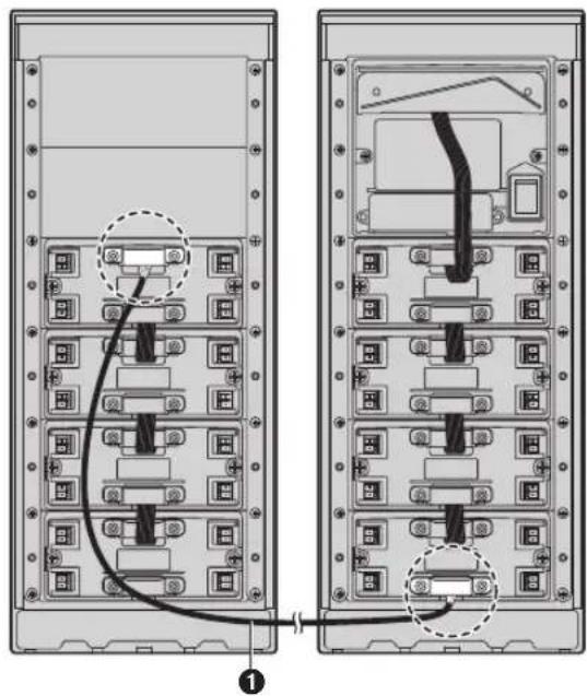
When connecting 2 frames of a lobby station together, connect them using the VL-VM801 extension cable (sold separately; ①) as shown below.
Example: lobby station for camera module × 1 pcs. + button module × 8 pcs. + blank panel × 2 pcs.
(2 of the included flat cables will not be used)
4.3.5 Connecting the VIGIK panel (forFrance)
The lobby station is compatible with VIGIK installation. Refer to the documentation of the VIGIK for information about installation.
Required items
– VIGIK system (user supplied)
– Cable that connects the lobby station to the VIGIK system (user supplied)
Supported sizes
When selecting a VIGIK system, select one that meets the following guidelines.
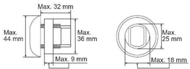
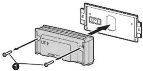
- Remove the waterproof rubber from the panel, and then remove the screws (①) on the left and right side of the module and panel.
- As shown in the following illustration, securely attach the VIGIK by following the instructions in the documentation for the VIGIK.
- The word "UP" should be facing up.
① Waterproof rubber (included with the VIGIK panel)
② VIGIK reader (user supplied)
③ Attachment nut or similar part (supplied with the VIGIK)
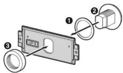
- Attach the VIGIK panel to the frame.
a. As shown in the following illustration, attach the VIGIK panel to the frame (1).
b. Securely attach the cable (user supplied; ②, ③) by following the instructions in the documentation for the VIGIK.
c. Align the protrusions of the cover with the holes of the plate (4).
d. Make sure to reattach the panel and module by securing the screws (5).
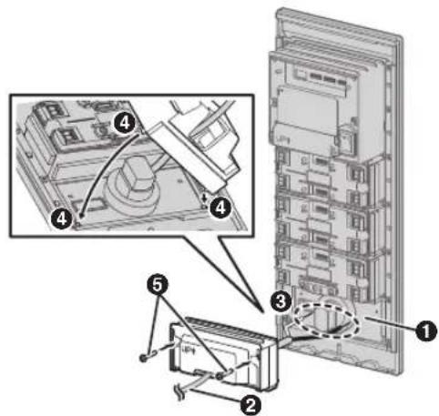
4.3.6 Installing the lobby station to a wall
The following 2 methods can be used for installing the lobby station.
- flush mounting using the back box (sold separately)
– surface mounting using the back box and surface mount cover (sold separately)
Back box dimensions and preparation
- Open a hole in the wall for the back box.
- Note the dimensions of the back box.
VL-VM603 (large type: back box)
Front view Side view
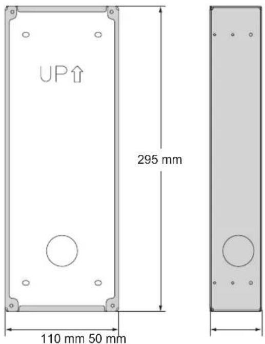
VL-VM602 (small type: back box)
Front view Side view
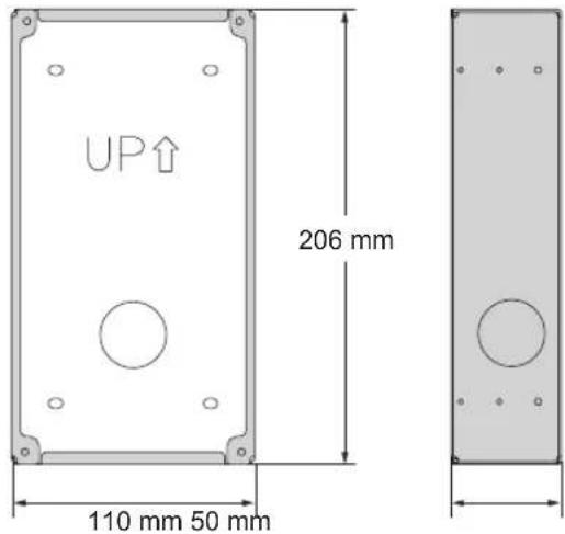
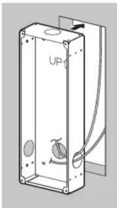
- Open the knockout holes of the back box, and then pass all the necessary cables and the following wires through the knockout holes.
- wires from the power supply unit
- wires from the electric lock, and K-IN connection device (example: access controller and/or open door sensor, etc.)
- wires from each main monitor, wires from the distributor, or wires from the extension box
natural_image
Technical line drawing of a rectangular enclosure with internal components and wiring (no text or symbols)4.3.7 Flush mounting using the back box
1 Open the knockout holes of the back box and pass cables through them.
- See the instructions in "Back box dimensions and preparation (Page 28)".
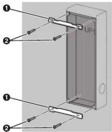
2 Install the back box in the wall.
3 Attach the upper and lower plates (①) using 4 screws (②) to the back box.
4 Set the DIP switches.
- See page 40 for information about lobby station DIP switches.
- See page 41 for information about distributor DIP switches when using bus wiring.
5 Connect the wires and cables to the lobby station.
- See 4.6.2 Wire type and maximum wire length (Page 39).
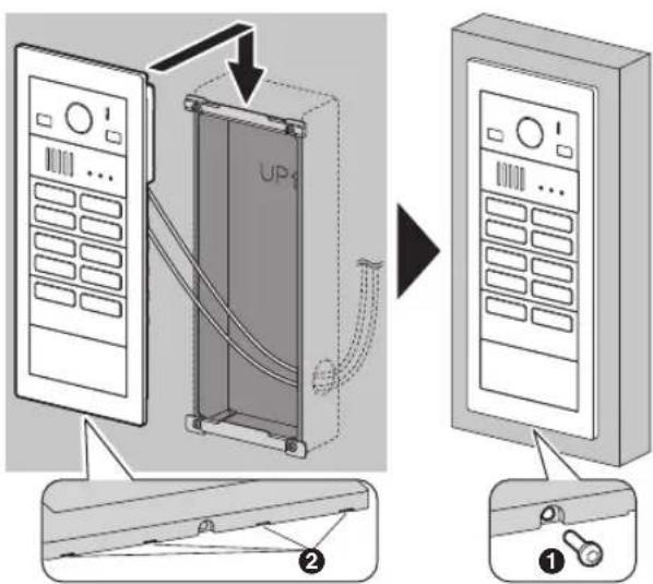
6 Attach the lobby station to the back box, and then use the hexalobular wrench to secure the lobby station to the back box using 1 hexalobular screw (①).
- Do not cover the water drain holes (②).
Note:
- Required pull-out capacity of a single screw is 294 N {30 kgf} or more. If this criteria is not met, make sure to take additional measures to increase strength.
Installing 2 frames of a lobby station
When connecting 2 frames of a lobby station together, use the extension cable (sold separately) and install to the wall as follows.
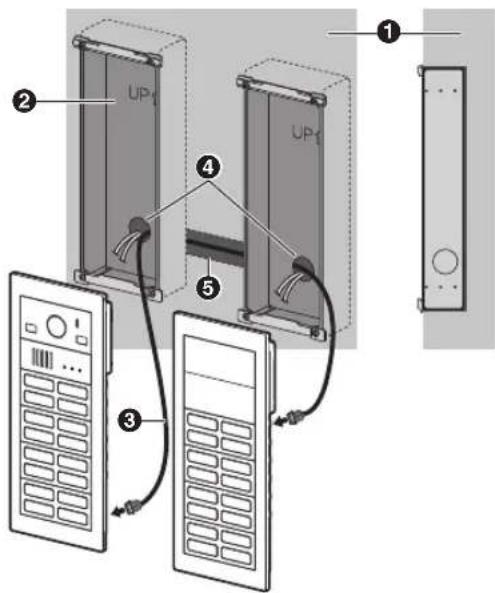
① Wall
② Back box
③ Extension cable (VL-VM801; sold separately) (approx. 1 m)
4 Holes
⑤ Pass extension cables from hole behind the wall.
4.3.8 Surface mounting using the back box and surface mount cover
1 Open the knockout holes of the back box and pass cables through them.
- See the instructions in "Back box dimensions and preparation (Page 28)".
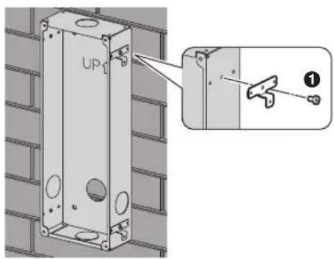
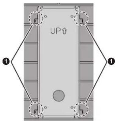
2 Use the hex wrench to secure the back box in 4 areas using 4 brackets and 4 hex screws (①), and then install the back box to the wall.
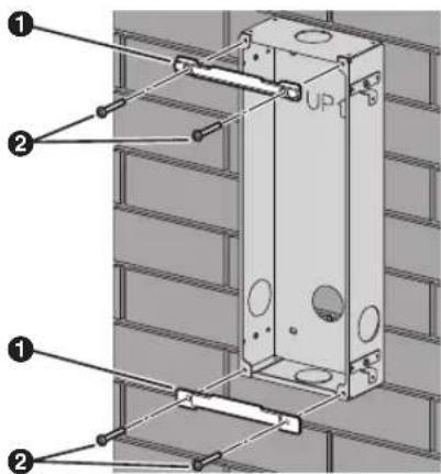
3 Attach the upper and lower plates (①) using 4 screws (②).
4 Set the DIP switches.
- See page 40 for information about lobby station DIP switches.
- See page 41 for information about the distributor DIP switches when using bus wiring.
5 Connect the wires and cables to the lobby station.
- See "4.6.2 Wire type and maximum wire length (Page 39)".
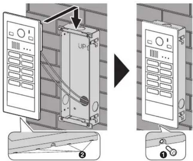
6 Attach the lobby station to the back box, and then use the hexalobular wrench to secure the lobby station to the back box using 1 hexalobular screw (①).
- Do not cover the water drain holes (②).
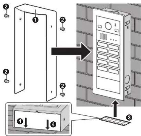
7 Attach the surface mount cover (①) to the back box.
a. Use the hex wrench to secure the surface mount cover in 4 areas using 4 hex screws (②). b. Remove the tape from both sides of the dustproof sheet (③), and then affix the dustproof sheet to the bottom side of the back box. Affix the dustproof sheet so that it aligns with the wall (④).
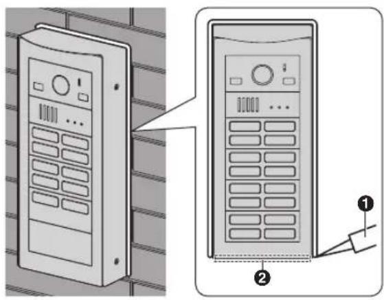
8 After securing the surface mount cover to the back box, caulk the top and side of the surface mount cover with water-resistant sealant. Do not caulk the bottom side.
Front view
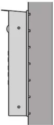
Side view
natural_image
Simple diagram of a vertical panel with mounting holes and a circular mark, no text or symbols present① Area caulked with water-resistant sealant
② Area not to be caulked
Note:
- Required pull-out capacity of a single screw is 294 N {30 kgf} or more. If this criteria is not met, make sure to take additional measures to increase strength.
Installing 2 frames of a lobby station
When connecting 2 frames of a lobby station together, use the extension cable (sold separately) and install to the wall as follows.
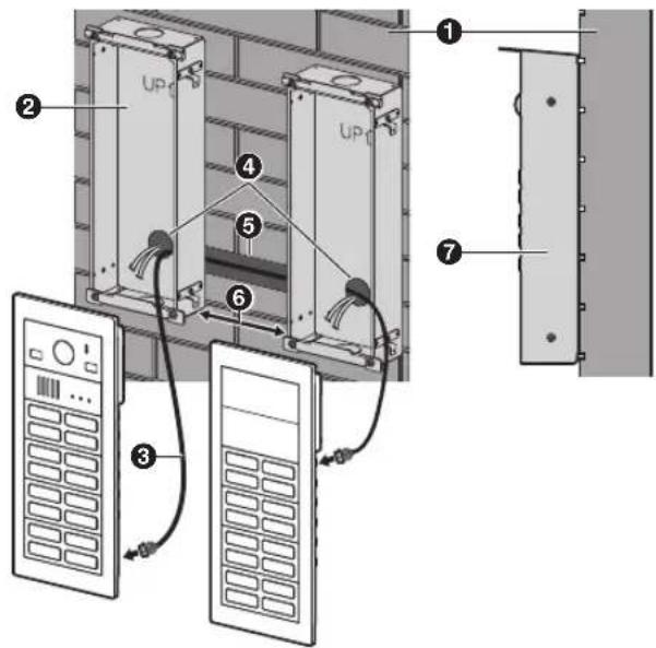
① Wall
② Back box
③ Extension cable (VL-VM801; sold separately) (approx. 1 m)
④ Holes
⑤ Pass extension cables from hole behind the wall.
6 Space is required to fasten screws when attaching the surface mount cover to the back box. When there are 2 frames for a lobby station, make sure that there is 6 cm or more space between the back boxes.
⑦ Illustration of the surface mount cover attached.
4.3.9 Connecting the wires
Important:
- Make sure you turn off the power to all devices at the breaker before performing any wiring work. Failure to observe this may cause product failure.
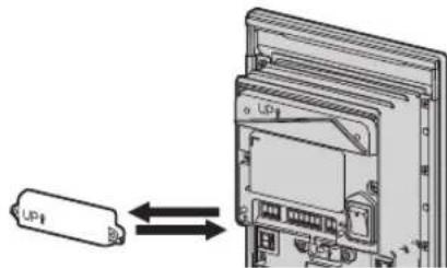
1 Remove the terminal cover from the camera module.
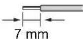
2 Strip the wires from all devices as below.
3 Insert the wires from the power supply unit into the DC terminal block, tighten the terminal block screws, and then attach the terminal block to the DC connection terminals.
- Connect the wires as follows. DC IN: Power supply unit
4 Insert the wires from the electric lock into the 3-pin terminal block, tighten the terminal block screws, and then attach the 3-pin terminal block to the K-OUT connection terminals.
- Connect the wires according to the specifications of the electric lock. Only 2 wire connections are needed.
NC and COM: For normally-open circuit type electric locks
COM and NO: For normally-closed circuit type electric locks
5 Insert the wires from the K-IN connection devices into the 6-pin terminal block, tighten the terminal block screws, and then attach the terminal block to the K-IN connection terminals.
- Connect the wires as follows. K-IN 1 C1 and C2/K-IN 2 C1 and C2: K-IN connection device (example: access controller and/or open door sensor, etc.)
Camera module
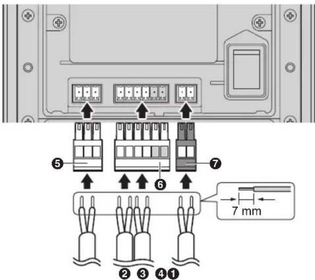
① Wires from electric lock
② Wires from access controller
③ Wires from open door sensor
④ DC wires from power supply unit
⑤ 3-pin terminal block
⑥ 6-pin terminal block
⑦ DC terminal block
6 When using star wiring:
Insert the wires from the main monitor into the 2-pin terminal block, tighten the terminal block screws, and then attach the terminal block to the line connection terminals.
- Connect the wires from the main monitor.
- When using star wiring, skip to step 8.
Example: 4-button module
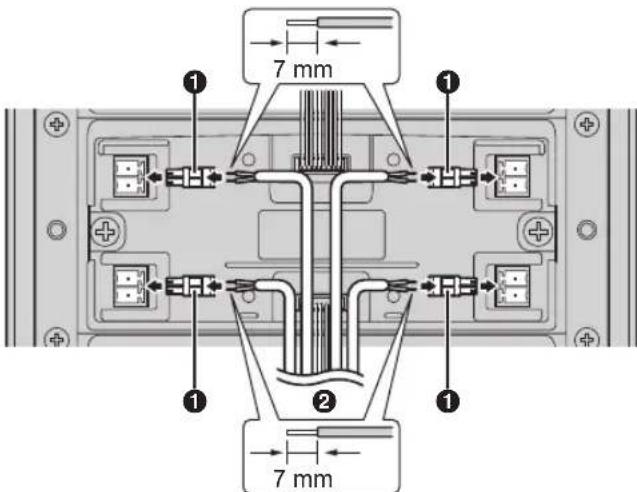
① 2-pin terminal block
② Wires from main monitor (star wiring)
7 When using bus wiring:
Insert the wires from the distributor or the extension box into the 6-pin terminal block, tighten the terminal block screws, and then attach the terminal block to the line connection terminals.
- Connect the wires as follows. L1 and L2: Distributor or extension box
Camera module
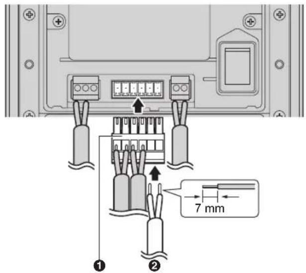
① 6-pin terminal block
② Wires from distributor or extension box (bus wiring)
8 Make sure to reattach the terminal cover to the terminal of the camera module.
9 When using bus wiring and a VL-V703 extension box:
Make the following connections for the extension box. Refer to the following items of the documentation of the VL-V900/VL-V901 series (including the VL-V703 extension box) for details about installation.
- Included items
- Device diagrams
- How to connecting wiring (stripping wires and cables, wire release button, or cable release button)
Download the documentation from the Web site below.
https://panasonic.net/cns/pcc/support/intercom/v900
a. Connect the wires from the power supply unit.
- Connect the wires as follows. DC IN: Power supply unit
b. Insert the wires from the lobby station.
- Connect the wires as follows. L1 and L2: Lobby station
c. Insert the wires from the distributor
- Connect the wires as follows. V700/VM701 L1 and L2: Distributor
10 When using bus wiring and VL-VM701 distributor:
Make the following connections for the distributor.
a. Remove the cable cover screws and then remove the cable covers.
Distributor
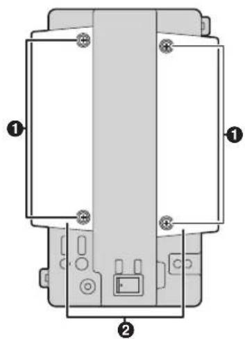
① Screws
② Cable covers
b. Insert the wires from the power supply unit into the DC terminal block, tighten the terminal block screws, and then attach the terminal block to the DC connection terminals.
- Connect the wires as follows. DC IN: Power supply unit
c. Insert the wires from the lobby station, extension box, or previous distributor into the 2-pin terminal block, tighten the terminal block screws, and then attach the terminal block to the connection terminals.
- Connect the wires as follows. IN VM101/VM701 L1 and L2: Lobby station, extension box, or previous distributor
d. Insert the wires from the next distributor into the 2-pin terminal block, tighten the terminal block screws, and then attach the terminal block to the connection terminals.
- Connect the wires as follows. OUT VM701 L1 and L2: Distributor
e. Insert the wires from the main monitor into the 2-pin terminal block, tighten the terminal block screws, and then attach the terminal block to the line connection terminals.
- Connect the wires as follows. D1 and D2: Main monitor
f. After wiring each terminal to the distributor, use the cable binders to secure the wires to the cable binder holes on the top and bottom on the distributor.
g. Make sure to reattach the cable covers and then securely fasten the cable cover screws.
Distributor
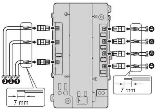
① DC wires from power supply unit
② Wires from lobby station, extension box, or previous distributor
③ Wires from next distributor
④ Wires from main monitor
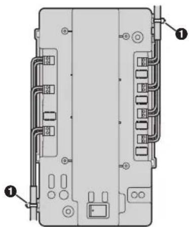
natural_image
Diagram of a device rear panel with labeled components (no text or symbols present)① Cable binders connected to cable binder holes
Note:
- Make sure the wires are inserted fully into the terminal block and that the terminal block screws are tight enough to prevent the wires from pulling out.
- Make sure each terminal block is securely connected to the connection terminals.
- Refer to "4.6.2 Wire type and maximum wire length (Page 39)" for connection diagrams.
- Refer to "4.6.2 Wire type and maximum wire length (Page 39)" for information on the type and length of wires that can be used.
4.4 Installing the extension box (sold separately)
Refer to the following items of the documentation of the VL-V900/VL-V901 series (including the VL-V703 extension box) for details about wall mounting installation.
- Included items
- Device diagrams
- Specifications
- Mounting on a DIN rail or attaching directly to a wall Download the documentation on the Web site below.
https://panasonic.net/cns/pcc/support/intercom/v900
4.5 Installing the distributor (sold separately)
Required items
– Distributor (VL-VM701; sold separately)
– Cable binders (included with distributor)
- Screws (included with distributor)
- Wires for the distributor connection (user supplied). See 4.6.2 Wire type and maximum wire length (Page 39).
Note:
- For more information about connections for the VL-VM701 distributor, refer to step 10 on page 33.
Installation methods
The following 2 methods can be used for installation.
- mounting on a DIN rail (user supplied)
- attaching directly to a wall
The following 2 methods can be used for installation. - mounting on a DIN rail (user supplied) - attaching directly to a wall
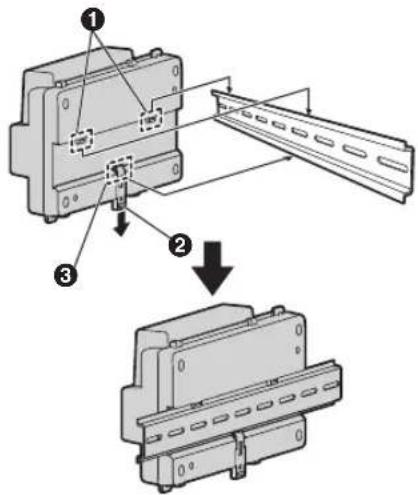
4.5.1 Mounting on a DIN rail
Attach the distributor to the DIN rail so that the bottom hook is positioned at the bottom of the distributor.
1 Hang the top hooks (①) of the distributor on the top of the DIN rail.
- At this point the distributor will be hanging from the DIN rail but will not be secure.
2 Pull the lever (②) down, make sure the bottom of the distributor is flat against the DIN rail, and then release to lever.
- The bottom hook (③) will slide up, securing the bottom of the distributor to the DIN rail.
4.5.2 Attaching directly to a wall
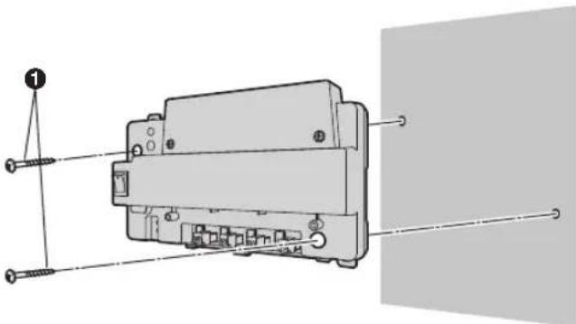
Attach the distributor to the wall securely using the 2 mounting screws (1).
- Attach the bottom cable cover after attaching the distributor to the wall.
natural_image
Technical diagram of an electrical switch assembly with screws and wiring (no text or labels)4.6 Wiring Connections
4.6.1 Wiring schematics
Note:
• See page 23 for information about connections for power supply units.
• See page 40 for information about lobby station DIP switch settings.
- See page 41 for information about distributor DIP switches when using bus wiring.
- Insert the wires fully into the connection terminals. After inserting the wires, pull slightly on each wire to make sure it is firmly connected.
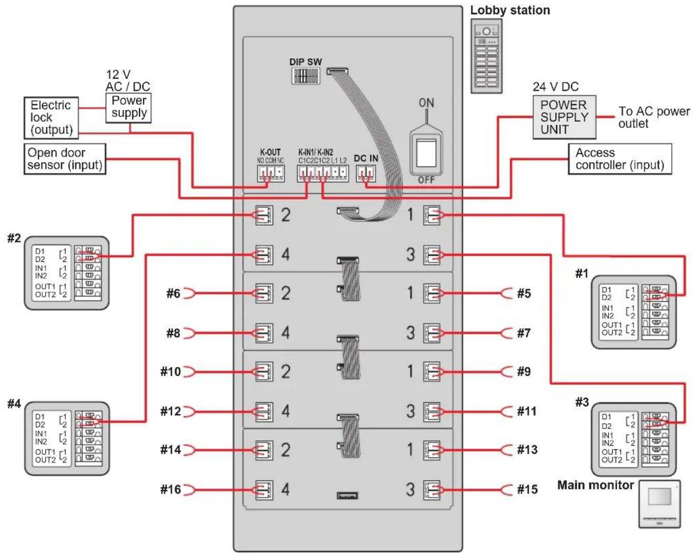
Star wiring example
Maximum number of devices
- Lobby station: up to 1
- Main monitor: up to 32 (depending on the composition of the lobby station's modules)
Important:
- When using star wiring, do not connect wires from main monitors to L1 and L2.
- Wiring is non-polarised.
flowchart
graph TD
    A["12 V AC / DC Power supply"] --> B["DIP SW"]
    C["Open door sensor (input)"] --> B
    B --> D["K-OUT NC COM VC"]
    B --> E["K-IN1/K-IN2 C1C2C1C2 L1 L2"]
    B --> F["DC IN"]
    B --> G["OFF"]
    H["Lobby station"] --> I["24 V DC POWER SUPPLY UNIT"]
    I --> J["To AC power outlet"]
    K["Access controller (input)"] --> L["#1"]
    L --> M["D1 D2 IN1 OUT1 OUT2"]
    L --> N["#3"]
    N --> O["D1 D2 IN1 OUT1 OUT2"]
    N --> P["#15"]
    Q["#2"] --> R["#6"]
    Q --> S["#8"]
    Q --> T["#10"]
    Q --> U["#12"]
    Q --> V["#14"]
    Q --> W["#16"]
    X["#3"] --> Y["#11"]
    X --> Z["#13"]
    X --> AA["#15"]
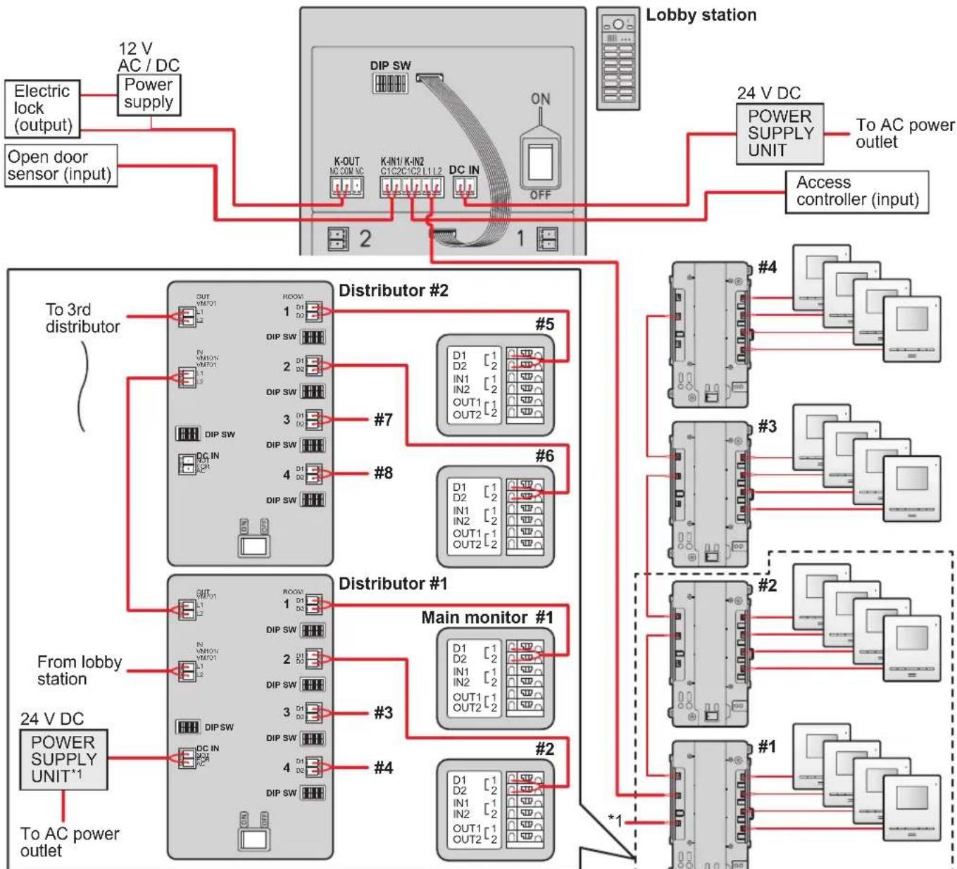
Bus wiring examples
Maximum number of devices
- Lobby station: up to 6
- Main monitor: up to 32 (depending on the composition of the lobby station's modules)
- Distributor: up to 8
- Extension box: up to 1 (required when expanding the lobby stations)
Using the distributor
Important:
- When using bus wiring, do not connect wires from main monitors to the terminals on the rear of the lobby station's button modules.
● Wiring is non-polarised.
flowchart
graph TD
    A["Lobby station"] --> B["12 V AC / DC Power supply"]
    A --> C["24 V DC POWER SUPPLY UNIT"]
    A --> D["To AC power outlet"]
    A --> E["Access controller (input)"]
    F["To 3rd distributor"] --> G["Distributor #2"]
    F --> H["Distributor #1"]
    F --> I["Main monitor #1"]
    J["Electric lock (output)"] --> K["Power supply"]
    L["Open door sensor (input)"] --> M["Power supply"]
    N["24 V DC POWER SUPPLY UNIT*1"] --> O["POWER SUPPLY UNIT*1"]
    P["From lobby station"] --> Q["Distributor #1"]
    P --> R["Distributor #2"]
    S["24 V DC POWER SUPPLY UNIT*1"] --> T["POWER SUPPLY UNIT*1"]
    U["To AC power outlet"] --> V["Power supply"]
    W["24 V DC POWER SUPPLY UNIT*1"] --> X["Power supply"]
    Y["Main monitor #1"] --> Z["Power supply"]
    AA["24 V DC POWER SUPPLY UNIT*1"] --> AB["Power supply"]
*1 : From 24 V DC POWER SUPPLY UNIT
Using the extension box and distributor
Important:
- When using bus wiring, do not connect wires from main monitors to the terminals on the rear of the lobby station's button modules.
- When connecting to an extension box:
-Set all DIP switches of the extension box (VL-V703) to off.
-Do not connect wires to connectors 2 to 4 for the V700/VM701 on the extension box (VL-V703).
—Cannot monitor from the main monitor.
Set DIP switch "8" for the lobby station to the "on" position (prohibits monitoring; page 40).
- Wiring is non-polarised.
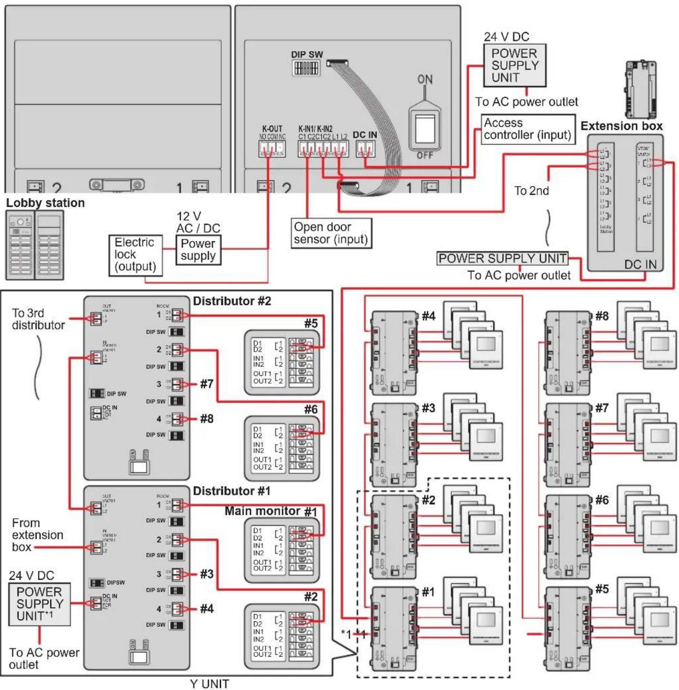
flowchart
graph TD
    subgraph Power_Supply_Units
        A["Lobby station"] --> B["Electric lock (output)"]
        B --> C["12 V AC / DC Power supply"]
        C --> D["Distributor #2"]
        D --> E["Main monitor #1"]
        E --> F["24 V DC POWER SUPPLY UNIT*1"]
        F --> G["To AC power outlet"]
    end

    subgraph Control_Supply_Units
        H["24 V DC POWER SUPPLY UNIT"] --> I["To AC power outlet"]
        I --> J["Access controller (input)"]
        J --> K["Extension box"]
    end

    subgraph Control_Supply_Units
        L["To AC power outlet"] --> M["Power Supply Unit"]
        M --> N["DC IN"]
    end

    style A fill:#f9f,stroke:#333
    style B fill:#f9f,stroke:#333
    style H fill:#ccf,stroke:#333
    style L fill:#ccf,stroke:#333
    style M fill:#ccf,stroke:#333
    style N fill:#ccf,stroke:#333
4.6.2 Wire type and maximum wire length
| Wiring run Wire diameter Max. length | |||||
| Star wiring | Lobby station | Main monitor | 0.65 mm (22 AWG) approx. 100 m | ||
| 1.2 mm (17 AWG) approx. 200 m | |||||
| Power supply unit(VL-PS240) | Lobby station | 0.65 mm (22 AWG) approx. 10 m | |||
| 2 mm (12 AWG) approx. 20 m | |||||
| Power supply unit(VL-PS2410) | Lobby station | 0.65 mm (22 AWG) approx. 50 m | |||
| 2 mm (12 AWG) approx. 100 m | |||||
| Bus wiring | Lobby station | DistributorThe farthest distributor | 0.65 mm (22 AWG) approx. 100 m | ||
| 1.2 mm (17 AWG) approx. 200 m | |||||
| Distributor*1 | Main monitor*2 | 0.65 mm (22 AWG) approx. 100 m | |||
| 1.2 mm (17 AWG) approx. 200 m | |||||
| Power supply unit(VL-PS240) | Lobby station | 0.65 mm (22 AWG) approx. 10 m | |||
| 2 mm ( 12 AWG) approx. 20 m | |||||
| Power supply unit(VL-PS2410) | Lobby station | 0.65 mm (22 AWG) approx. 50 m | |||
| 2 mm (12 AWG) approx. 100 m | |||||
| Power supply unit(VL-PS240)Power supply unit(VL-PS2410) | Distributor | 0.65 mm (22 AWG) approx. 10 m | |||
| 2 mm (12 AWG) approx. 20 m | |||||
| Power supply unit | AC power source | 1.2 mm (17 AWG) | No requirement | ||
| 2 mm (12 AWG) | |||||
| Lobby station | Electric lockK-IN connection device(example: access controllerand/or open door sensor,etc.) | 0.5 mm (24 AWG) According tospecification ofconnected device. | |||
| 1.2 mm (17 AWG) | |||||
*1 Distributor connected to a power supply unit (when using VL-MV10 main monitors)
*2 The farthest main monitor (when using VL-MV10 main monitors)
Note the following when selecting wiring
- Use 2-conductor (solid copper) wiring with a PE (polyethylene)-insulated PVC jacket. Mid-capacitance, non-shielded cable is recommended.
- A certified power supply wiring has to be used with this equipment. The relevant national installation and/or equipment regulations shall be considered. A certified power supply wiring not lighter than ordinary polyvinyl chloride flexible wiring according to IEC 60227 shall be used.
- When an extension box is connected, the maximum wire length from the lobby station to the distributor does not change.
4.7 DIP switch settings
4.7.1 Lobby station DIP switch settings
The following lobby station DIP switch settings are required when installing the lobby station.
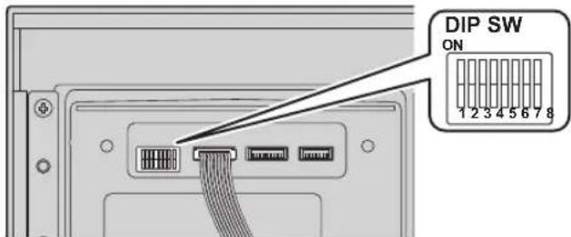
| Item Setting | DIP switch Item | Setting DIP switch | |||
| Wiring method | Star wiring | ONOFF1 2 3 4 5 6 7 | Audio guidance language (when unlocking a door) | No audio guidance | ONOFF1 2 3 4 5 6 7 |
| Bus wiring | ONOFF1 2 3 4 5 6 7 | English | ONOFF1 2 3 4 5 6 7 | ||
| Backlighting for call buttons in standby mode | Turns on in dark condition | ONOFF1 2 3 4 5 6 7 | German | ONOFF1 2 3 4 5 6 7 | |
| Always on | ONOFF1 2 3 4 5 6 7 | French | ONOFF1 2 3 4 5 6 7 | ||
| Always off | ONOFF1 2 3 4 5 6 7 | Spanish | ONOFF1 2 3 4 5 6 7 | ||
| Prohibit monitoring from a main monitor● When using a VL-V703 (extension box), set DIP switch "8" to the "on" position (prohibits monitoring). | ONOFF1 2 3 4 5 6 7 | Italian | ONOFF1 2 3 4 5 6 7 | ||
| Allow monitoring from a main monitor | ONOFF1 2 3 4 5 6 7 | Dutch | ONOFF1 2 3 4 5 6 7 | ||
| Arabic | ONOFF1 2 3 4 5 6 7 | ||||
| Persian | ONOFF1 2 3 4 5 6 7 | ||||
4.7.2 Distributor DIP switch settings
The following DIP switch settings are required when installing the distributor using bus wiring.
- Distributor ID settings #1 – #8: applicable DIP switches (①) must be configured at each distributor.
- Room number ID settings ① – ③: applicable DIP switches (②) must be configured according to each button number of the lobby stations and rooms.
A: For the purpose of an explanation, numbers are written on the name plates of each call button of the lobby stations.
Example: When configuring room number 20, set the DIP switch of the applicable distributors ⑳.
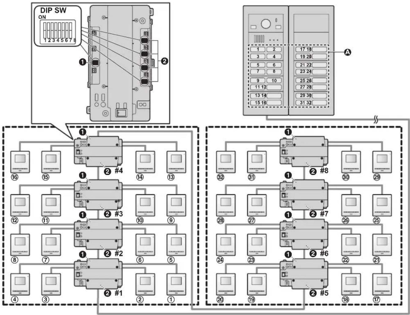
flowchart
graph TD
    subgraph_Top_Dip_DIP["Top DIP Switch"]
        A1["Device 1"] --> B1["Device 2"]
        B1 --> C1["Device 3"]
        C1 --> D1["Device 4"]
        D1 --> E1["Device 5"]
        E1 --> F1["Device 6"]
        F1 --> G1["Device 7"]
        G1 --> H1["Device 8"]
        H1 --> I1["Device 9"]
        I1 --> J1["Device 10"]
        J1 --> K1["Device 11"]
        K1 --> L1["Device 12"]
        L1 --> M1["Device 13"]
        M1 --> N1["Device 14"]
        N1 --> O1["Device 15"]
        O1 --> P1["Device 16"]
        P1 --> Q1["Device 17"]
        Q1 --> R1["Device 18"]
        R1 --> S1["Device 19"]
        S1 --> T1["Device 20"]
        T1 --> U1["Device 21"]
        U1 --> V1["Device 22"]
        V1 --> W1["Device 23"]
        W1 --> X1["Device 24"]
        X1 --> Y1["Device 25"]
        Y1 --> Z1["Device 26"]
        Z1 --> AA1["Device 27"]
        AA1 --> AB1["Device 28"]
        AB1 --> AC1["Device 29"]
    end

    subgraph Bottom_Bottom
        B2["Device 2"] --> C2["Device 3"]
        C2 --> D2["Device 4"]
        D2 --> E2["Device 5"]
        E2 --> F2["Device 6"]
        F2 --> G2["Device 7"]
        G2 --> H2["Device 8"]
        H2 --> I2["Device 9"]
        I2 --> J2["Device 10"]
        J2 --> K2["Device 11"]
        K2 --> L2["Device 12"]
        L2 --> M2["Device 13"]
        M2 --> N2["Device 14"]
        N2 --> O2["Device 15"]
        O2 --> P2["Device 16"]
        P2 --> Q2["Device 17"]
        Q2 --> R2["Device 18"]
        R2 --> S2["Device 19"]
        S2 --> T2["Device 20"]
        T2 --> U2["Device 21"]
        U2 --> V2["Device 22"]
        V2 --> W2["Device 23"]
        W2 --> X2["Device 24"]
        X2 --> Y2["Device 25"]
        Y2 --> Z2["Device 26"]
        Z2 --> AA2["Device 27"]
        AA2 --> AB2["Device 28"]
        AB2 --> AC2["Device 29"]
    end

    Top_Bottom_Left
    Top_Bottom_Right_Left
    Bottom_Bottom_Dirt
    Bottom_Bottom_High
    Bottom_Bottom_Lower
    Bottom_Bottom_High
    Bottom_Bottom_Lower
    Bottom_Bottom_High
    Bottom_Bottom_High
    Bottom_Bottom_High
    Bottom_Bottom_High
    Bottom_Bottom_High
    Bottom_Bottom_High
    Bottom_Bottom_High
    Bottom_Bottom_High
    Bottom_Bottom_High
    Bottom_Bottom_High
    Bottom_Bottom_High
    Bottom_Bottom_High
    Bottom_Bottom_High
    Bottom_Bottom_High
    Bottom_Bottom_High
</details>
Distributor ID settings ①
<table><tr><td>Setting DIP</td><td colspan="3">switch Setting DIP switch Termination DIP switch</td><td></td><td></td></tr><tr><td>Distributor ID #1</td><td>ONOFF1 2 3 4 5 6 7</td><td>Distributor ID #5</td><td>ONOFF1 2 3 4 5 6 7</td><td rowspan="2">Farthest end distributor</td><td rowspan="2">ONOFF1 2 3 4 5 6 7</td></tr><tr><td>Distributor ID #2</td><td>ONOFF1 2 3 4 5 6 7</td><td>Distributor ID #6</td><td>ONOFF1 2 3 4 5 6 7</td></tr><tr><td>Distributor ID #3</td><td>ONOFF1 2 3 4 5 6 7</td><td>Distributor ID #7</td><td>ONOFF1 2 3 4 5 6 7</td><td rowspan="2">Not farthest end distributor</td><td rowspan="2">ONOFF1 2 3 4 5 6 7</td></tr><tr><td>Distributor ID #4</td><td>ONOFF1 2 3 4 5 6 7</td><td>Distributor ID #8</td><td>ONOFF1 2 3 4 5 6 7</td></tr></table>
Room number ID settings ②
<table><tr><td colspan="2">Setting DIP switch Setting DIP switch</td><td></td><td></td></tr><tr><td>Button 1</td><td><img src="images/0cff843f80c8081f62c2b1f8bd2e0c125eb68a6be5ccc4e6119d3a1e8cefb7d2.jpg"/></td><td>Button 17</td><td><img src="images/1b3c87ffaa1bf9dfe36a67cd622de3e23285944871d12c79aea77d7c0eb17590.jpg"/></td></tr><tr><td>Button 2</td><td><img src="images/0a657973366301f46f028356bb2b5c2542e38d1b1ba020cea9c58174eb23084c.jpg"/></td><td>Button 18</td><td><img src="images/606808f88c53acbcdf333692a429757a4e6ec788866baf389505cc7c32cd33cc.jpg"/></td></tr><tr><td>Button 3</td><td><img src="images/552584df47f6aa903c81f07b72011c9dbd8f92b1a0824836a1ebda25e7dcb5b5.jpg"/></td><td>Button 19</td><td><img src="images/93e199d7a9ae1f708eadf920e9b92ec350fe411c93086312a7a95a106e97fe04.jpg"/></td></tr><tr><td>Button 4</td><td><img src="images/3958ccb369290d779de2e6dcf66976fb5be2727e77b1dbce33c80fc967fc9320.jpg"/></td><td>Button 20</td><td><img src="images/9536616ee7d3c9d72a99bcd89e8771210a2605f528ba95ba5f43e67f6198de78.jpg"/></td></tr><tr><td>Button 5</td><td><img src="images/1ca6c2dd7523960715e232677ba6f00487b23bf4e814102c5b45609348811e16.jpg"/></td><td>Button 21</td><td><img src="images/02e294b34600992d86494306aea3c03b62c75447a5fdb833bd1b24b5b73f6752.jpg"/></td></tr><tr><td>Button 6</td><td><img src="images/24b27130dcb4bec45a9a5d3e214f1108c050797fb82e5a9c1e7bdd522d18cdb6.jpg"/></td><td>Button 22</td><td><img src="images/c4bf4a525a1644f24adeb3903d6e5a16b1c604b37f8e8b065e3394653f3efa56.jpg"/></td></tr><tr><td>Button 7</td><td><img src="images/6f7ac719cb3a1eb86a57c0614391d75e501a38b9e69f33b6db896a82116acd42.jpg"/></td><td>Button 23</td><td><img src="images/4d60473eb36bb9341f7826358f463586cd478512e72666e559a77e4265998eb8.jpg"/></td></tr><tr><td>Button 8</td><td><img src="images/128e189c5ddf6436c885c3efb2019bf4d5abe62df4b1ec9e13e88c9b0331a3f7.jpg"/></td><td>Button 24</td><td><img src="images/0d7d045286daa0a86824a7fa9d4227b1b69ffde36e3946975980c38f5b1ab386.jpg"/></td></tr><tr><td>Button 9</td><td><img src="images/b9a239fa04d722863d983a223570d7cb0dfa998b9af10d357154d24d5978fb8c.jpg"/></td><td>Button 25</td><td><img src="images/7fe99d5f016967180be270b7367c7025582bdb97ad4765fb9ee740a55f6c1eae.jpg"/></td></tr><tr><td>Button 10</td><td><img src="images/d8411c10f647d014dd795a4be59c7ee9f887ad05abbdf2c9826cfffd42d59bb9.jpg"/></td><td>Button 26</td><td><img src="images/8679690c23104639bf81c93a6f2516db0409f6d294c48dc53f2a2128f3cf63b0.jpg"/></td></tr><tr><td>Button 11</td><td><img src="images/fb152b1969df1fb93e1aab471428233debfe4ba20fd205749ef5f3ba184e2eaa.jpg"/></td><td>Button 27</td><td><img src="images/8aae28b9c6843cec8c3ebcf2df2fc42b60a5a5cd44b786b98f6f3eb7ecfc47f6.jpg"/></td></tr><tr><td>Button 12</td><td><img src="images/a907893077a0ad4b590311e49918c633d9fd7231167a927e494c6e266fd5e8ee.jpg"/></td><td>Button 28</td><td><img src="images/92695209371a25c05187efe6d762f4c27cad27588869598f285d5a46ac8c30a9.jpg"/></td></tr><tr><td>Button 13</td><td><img src="images/139ffa5d767e81af52a6ee57170bb36b34de79d32de39d81e0f4e035d319240d.jpg"/></td><td>Button 29</td><td><img src="images/42173a8d32225a14021b4e1cdf94e82ab814f1023344cfa38260aa59ac3123c2.jpg"/></td></tr><tr><td>Button 14</td><td><img src="images/10bcfc6abcb18a0f0b49a7919cceaf519263d33b653f3ae43b86a75cb3a260d1.jpg"/></td><td>Button 30</td><td><img src="images/a41e5afaf56123d9e833730fb175e971f0a0ce8167489a57494923552d46eab4.jpg"/></td></tr><tr><td>Button 15</td><td><img src="images/34b41042d99f14d0e3929528df1e608550bd1d0c6f0135ea040cc2c6bcc55866.jpg"/></td><td>Button 31</td><td><img src="images/617f571d2125efb26fe0292693b45975976ef27cf3655f2e4a24217a9b76dc7a.jpg"/></td></tr><tr><td>Button 16</td><td><img src="images/c1442e403679dbff5d828f7b0ac8927c0f8027e1ae7d2ee6cc5292acb861f4cb.jpg"/></td><td>Button 32</td><td><img src="images/e0bc8e8adc1abd6fe9f5d29e3475e75567507eae1bc2352f18ae19c200f60984.jpg"/></td></tr></table>
<h1 id="48-distributor-power-and-access-indicators">4.8 Distributor POWER and ACCESS indicators</h1>
You can use the POWER and ACCESS indicators to check the status of devices.
- All distributors lit in green indicate that there is no problem.
- A red flashing indicator indicates that there is an error.
<table><tr><td>Category Meaning</td><td>POWER (green) ACCESS (red)</td><td></td><td></td></tr><tr><td rowspan="2">Normal operation</td><td>Idle Lit Off</td><td></td><td></td></tr><tr><td>Call or monitoring in progress Lit Lit</td><td></td><td></td></tr><tr><td rowspan="3" colspan="2">Error All DIP switches are in the "off" position Lit Flashing slowly</td><td></td><td></td></tr><tr><td>The DIP switch positions used for distributor ID settings are not permitted</td><td>Lit Flashing slowly</td></tr><tr><td>DIP switches for distributor ID settings "5", "6", and "7" are in the "on" positionDIP switches for room number ID settings "7" and "8" are in the "on" position</td><td>Lit Flashing slowly</td></tr></table>
<h1 id="49-connecting-other-devices">4.9 Connecting other devices</h1>
<h1 id="491-electric-locks">4.9.1 Electric locks</h1>
You can connect an electric lock to each lobby station via the K-OUT connection terminals. An electric lock is used to open the entrance door in conjunction with another action, such as pressing a button, swiping an access card, inserting a key, entering a door access password, etc.
- One electric lock can be connected to each lobby station.
- When selecting an electric lock, select a device that meets the following guidelines.
\- N/C or N/O dry closure contact
\- 12 V AC/DC, less than 1 A
\- After connecting an electric lock to the lobby station, confirm that the electric lock can properly lock doors, and if a main monitor can be used to unlock electric locks.
You can also select the length of time control signals are sent to unlock the electric locks (turn on K-OUT) using a main monitor.
(How long the entrance door remains unlocked depends on each electric lock's specification.)
For detailed information about setting configuration of electric locks, refer to the documentation included with the electric lock.
\- Operations for configuring an electric lock differ depending on the model of the main monitor.
Refer to the documentation included with your main monitor ^*1 for information about "Configuring electric locks".
\*1 Please note that the "Doorphone" setting name shown in the product display and documentation of the main monitor has the meaning of "Lobby station".
<h1 id="492-k-in-connection-devices">4.9.2 K-IN connection devices</h1>
You can connect an access controller and/or open door sensors, etc. to each lobby station via the K-IN connection terminals. K-IN connection terminals are used to determine whether the user is allowed to open the door using a push button, key switch, card reader, etc.
The K-IN connection device works together with the electric lock. The electric lock signal is set to unlock only for the time there is an input to K-IN.
The length of time control signals are sent to unlock the electric locks (turn on K-OUT) is the input time of K-IN plus 5 seconds.
- One K-IN 1 connection device and one K-IN 2 connection device can be connected to each lobby station.
- For detailed information about setting configuration of K-IN connection devices, refer to the documentation included with the K-IN connection devices.
<h1 id="410-room-name-plates">4.10 Room name plates</h1>
The room name plates of the lobby station can be attached in the follow ways.
- Attached so that room name plates can be easily attached and removed in order to change the names of residents.
- Attached so that room name plates cannot be easily attached and removed (tamper prevention). After consulting with contractors and facility staff, use screws to secure each name button module to the lobby station.
<h1 id="removingattaching-room-name-plates">Removing/attaching room name plates</h1>
1. Remove the name plate button as shown in (①) and (②) below.
2. Remove the name plate by sliding it (③) out from the button.
3. Remove the name plate as shown in (4) below and change the contents of the name plate.
4. Reattach the name plate button as shown in (5) below.
\- Make sure that the name plate button is securely attached.

<details>
<summary>flowchart</summary>
```mermaid
graph TD
A["Device 1"] --> B["Inserted Panel"]
B --> C["Reassembly to Panel 3"]
C --> D["Reassembly to Panel 4"]
D --> E["Reassembly to Panel 5"]
Attaching the room name plates so that they cannot be easily removed
- Remove the screws (①) on the left and right side of the button module and panel, and then remove the button module and panel.
- As shown in the following illustrations, from the rear of the button module, secure the left and right sides of the button module with screws (②).
- The number of included screws used differs depending on the button module used. Refer to page 10 for information.
- Reattach the button module and panel by securing the screws (③) on the left and right side of the button module and panel. Make sure the panel is securely attached.
Example: 4-button module
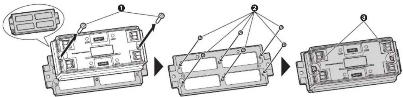
5.1 System conditions and limitations
Please note the following system conditions and limitations.
- Only one call or monitoring session can be handled at a time.
- If the call button for the same lobby station is pressed multiple times, the last call button pressed has priority.
- If the call buttons for multiple lobby stations are pressed, the first call button pressed has priority.
-
The main monitor cannot monitor with the lobby station when the lobby station is in use (monitoring with other devices, on call).
-
When lobby stations are connected to extension boxes, main monitors cannot monitor the outside with any of the lobby stations.
- Even when multiple lobby stations are connected to an extension box☐01 is displayed for all of the lobby stations (except for VL-MV10 (bus-powered main monitor)).
- All calls and monitoring sessions are disconnected after the "timeout" time elapses. The time is 90 seconds for calls and 180 seconds for monitoring.
5.2 Lobby station operations
5.2.1 Calling a resident
Enter the resident's call button to call.
• indicator flashes in red while calling the resident.
- After the resident answers the call, indicator lights in amber.
- When the door is unlocked, the audio guidance is announced from the lobby station, and the O-m indicator lights in blue.
6.1 Basic troubleshooting
For advanced troubleshooting, refer the information on the following web site.
https://panasonic.net/cns/pcc/support/intercom/vl-vm
If the system does not operate correctly, particularly after installing or modifying the system, first check the following points.
● Power is supplied to each device
- All cables are connected correctly and fully inserted into the terminals (see page 36 to 39)
- The in/out connections between units are correct (see page 36 to 38)
- The DIP switch settings for the lobby station are correct (see page 40)
● The DIP switch settings for the distributor are correct (see page 41 to 42)
Red lit or flashing indicators for the distributor
Indicators lit or flashing in red indicate there is an error. See "4.8 Distributor POWER and ACCESS indicators (Page 43)" for more information.
General issues
| Problem Cause & Solution Page | ||
| Calls are disconnected. ● The call with higher priority was made by pressing a button on another lobby station, causing the current call to be disconnected.→ Wait and try again later.The current call timed out and was disconnected.→ To conserve system resources, all calls time out and are disconnected after a programmed amount of time. | 45 | |
| Cannot monitor lobby stations from the main monitor. | ● Lobby stations connected to extension boxes may not be able to be monitored from main monitors.● Another lobby station and the main monitor are on a call. | 38 |
| Cannot monitor lobby stations selected from the monitor list on the main monitor. | ● If the selected lobby station is connected to an extension box, it may not be able to be monitored from main monitors. | 38 |
Main monitor display issues
| Image from Display Cause & Solution Page | |||
| Lobby station ● | No image is displayed.● Images have poor quality. | ● The cables are not correctly connected.→ Check cable connections and make sure that all cables are fully inserted into the terminals.● Power is not connected to all units.→ Check the power connection and connect power to all units. | 36, 39 |
| ● “Doorphone unavailable” is displayed. | ● It is displayed when calls from the lobby station are disconnected.→ This is not a device malfunction. Wait for the message to disappear from the display.● It is displayed when monitoring a lobby station when another main monitor is already on call with or monitoring the lobby station.→ This is not a device malfunction. Either wait for the message to disappear from the display or press the OFF button. | - | |
6.2 Cleaning
Wipe the product with a soft, dry cloth.
- For excessive dirt, wipe the product with a slightly damp cloth.
- When the product is installed near ocean coasts, wipe the product with a slightly damp cloth once every 2 to 3 months.
Important:
- Do not use any cleaning products that contain alcohol, polish powder, powder soap, benzine, thinner, wax, petroleum, or boiling water. Also do not spray the product with insecticide, glass cleaner, or hair spray. This may cause a change in colour or quality of the product.
6.3 Terms and illustrations in this document
- Model number suffixes (e.g., the "EX" in "VL-VM101EX") are omitted unless necessary.
- Design and specifications are subject to change without notice.
● Illustrations may vary slightly from the actual product.
6.4 Trademarks (for France)
- VIGIK® is a registered trademark of La Poste.
- All other trademarks identified herein are the property of their respective owners.
Panasonic Corporation
1006, Oaza Kadoma, Kadoma-shi, Osaka 571-8501, Japan
http://www.panasonic.com
© Panasonic Corporation 2018
- Installation and Operating Instructions
- Note to the installer
- Introduction
- Important Information
- Preparation
- Installation
- Basic Operations
- Other information
- System overview
- Main features
- Easy installation
- Easy maintenance
- System configuration
- Star wiring example
- Bus wiring example
- System devices
- Lobby station components
- Note:
- Important safety information
- WARNING
- Preventing fire, electric shock and short circuits
- Preventing accidents
- CAUTION
- Preventing accidents, injuries, and property damage
- Important safety instructions
- SAVE THESE INSTRUCTIONS
- Privacy and rights of portrait
- Disclaimer
- Other important information
- General information
- For business users in the European Union
- Information on Disposal in other Countries outside the European Union
- For India only
- Declaration of Conformity with the requirements of the E-Waste (Management) Rules
- Disposal information
- For Europe
- Ecodesign information
- System devices
- Lobby station
- Distributor
- Power supply unit
- Device diagrams
- Lobby station
- Distributor
- Specifications
- Whole system capacity
- Distributor (VL-VM701; sold separately)
- Power supply unit (VL-PS240; sold separately)
- Power supply unit (VL-PS2410; sold separately)
- Installation cautions
- Installing the power supply unit (sold separately)
- Required items
- Installation location
- Installation methods
- Connecting the AC wires and DC wires (VL-PS240)
- Connecting the AC wires and DC wires (VL-PS2410)
- Information about the power supply unit
- Power supply for distributors and wiring for power supply units
- ■ Number of operable VL-VM701 (distributors)
- Example: when a VL-MV10 is connected using 1 VL-PS2410 power supply unit
- Mounting on a DIN rail
- Attaching directly to a wall
- Installing the lobby station
- Installation position of the lobby station and camera range
- Side view
- Top view
- Assembling lobby station modules
- Connecting flat cables
- Connecting 2 frames of a lobby station using the extension cable
- Connecting the VIGIK panel (forFrance)
- Supported sizes
- Installing the lobby station to a wall
- Back box dimensions and preparation
- VL-VM603 (large type: back box)
- VL-VM602 (small type: back box)
- Flush mounting using the back box
- Installing 2 frames of a lobby station
- Surface mounting using the back box and surface mount cover
- Connecting the wires
- Important:
- When using star wiring:
- When using bus wiring:
- When using bus wiring and a VL-V703 extension box:
- When using bus wiring and VL-VM701 distributor:
- Installing the extension box (sold separately)
- Installing the distributor (sold separately)
- Mounting on a DIN rail
- Attaching directly to a wall
- Wiring Connections
- Wiring schematics
- Maximum number of devices
- Bus wiring examples
- Using the distributor
- Note the following when selecting wiring
- DIP switch settings
- Lobby station DIP switch settings
- Distributor DIP switch settings
- Attaching the room name plates so that they cannot be easily removed
- Example: 4-button module
- System conditions and limitations
- Lobby station operations
- Calling a resident
- Basic troubleshooting
- Red lit or flashing indicators for the distributor
- Cleaning
- Terms and illustrations in this document
- Trademarks (for France)
- Panasonic Corporation
Brand : PANASONIC
Model : VL-VM801
Category : Doorbell