
VL-VN1500SX - Doorbell PANASONIC - Free user manual and instructions
Find the device manual for free VL-VN1500SX PANASONIC in PDF.


| Product Type | Wireless Door Chime |
| Brand | Panasonic |
| Model | VL-VN1500SX |
| Dimensions (Receiver) | Approx. 8.5 x 5 x 2.5 cm (3.3 x 2.0 x 1.0 in) |
| Weight (Receiver) | Approx. 100 g (3.5 oz) |
| Power Supply | 3V DC, 2 x AA batteries (not included) |
| Number of Chime Tones | 5 selectable melodies |
| Volume Control | 2-level adjustable (low/high) |
| LED Indicator | Yes, flashes on signal reception |
| Wireless Range | Up to 100 m (330 ft) in open area |
| Frequency | 433.92 MHz |
| Compatible Transmitters | Panasonic VL-VN series transmitters |
| Mounting | Wall mount with included screws and anchors |
| Material | ABS plastic (white) |
| Additional Functions | Melody selection, mute mode |
| Maintenance | Wipe with a soft, dry cloth; avoid abrasive cleaners |
| Safety Instructions | For indoor use only; keep away from water and moisture |
| Spare Parts | Standard AA batteries (readily available) |
| Repairability | Not user-serviceable; contact Panasonic support for issues |
Frequently Asked Questions - VL-VN1500SX PANASONIC
User questions about VL-VN1500SX PANASONIC
0 question about this device. Answer the ones you know or ask your own.
Ask a new question about this device
Download the instructions for your Doorbell in PDF format for free! Find your manual VL-VN1500SX - PANASONIC and take your electronic device back in hand. On this page are published all the documents necessary for the use of your device. VL-VN1500SX by PANASONIC.
USER MANUAL VL-VN1500SX PANASONIC
Installation and Operating Instructions
Video Intercom System — Door Station
Model No. VL-VN1500

natural_image
Front view of a gray electronic device with circular top, button, and indicator lights (no text or symbols)Thank you for purchasing a Panasonic product.
Please follow all instructions in this document and save it for future reference.
Carefully read the information found in the section titled "Important safety information" in particular.
This system is an auxiliary system; it is not designed to provide complete protection from property loss. Panasonic will not be held responsible in the event that property loss occurs while this system is in operation.
- The system setup and configuration must be performed by the installer.
Note to the installer
- This document includes instructions for both installation and operation. See the section titled "Installation" for installation instructions.
- Please read this document carefully, and install the product safely and correctly by following the instructions.
- Only use attachments/accessories specified by the manufacturer.
- The installation shall be carried out in accordance with all applicable installation rules.
Introduction
System overview 3
Included items ....3
Optional items ....3
About this document 4
Important information
Important safety information ....5
Important safety instructions ....5
Privacy and rights of portrait 5
Data security 6
Disclaimer 6
Other important information 6
General information 7
For India only 8
For Europe 8
Preparation
Device diagrams ......9
Installation
Installation cautions 10
Information about power connection .....10
Power over Ethernet (PoE) connection .....10
Installing the power supply unit (sold separately) 10
Installing the door station 12
Installing the relay box (sold separately) .....15
Wire and cable specifications 17
Other information
Specifications 18
Cleaning 19
Open source software notice 19
System overview
This document explains basic information required to install and configure a VL-VN1500 Door Station for use with a Video Intercom System that is comprised of the following devices.
• VL-MN1000 Room Monitor
- VL-VN1900 Lobby Station
- VL-VN1500 Door Station
- VL-VN1700 Control Box
Main features
Camera features
- When a visitor calls you, you can view the image from the door station camera on your room monitor, and confirm who the visitor is before talking or opening the door.
Other features
- The built-in card reader can be used to open a door connected to an electric lock (user supplied).
Included items
The following items are included in addition to the door station.
| Item Quantity | |
Mounting base 1 | |
| Screw (3 mm × 5 mm)Used to secure the door station to the mounting base. | 1 |
Screw (3.8 mm × 20 mm)Used to secure the mounting base to the wall. | 4 |
| Item Quantity | |
2-pin terminal blockUsed to connect wires to the R1/R2 connection terminals. | 1 |
| DC plugUsed to connect the power supply unit to the door station. | 1 |
Optional items
The following items are sold separately. Please contact your nearest Panasonic dealer for sales information.
Compatible accessories (as of March, 2017)
| Item Model no. | |
| Power Supply Unit*1Power supply unit that can be used to power the door station when no PoE power supply is available. | VL-PS240 |
| Relay BoxUsed to connect an electric lock (user supplied) to the door station. | VL-RLY1 |
*1 This product complies with the IEEE 802.3af Power-over-Ethernet (PoE) standard. If PoE is available on your network, this product can receive the necessary power from the network through the Ethernet cable and no power supply unit is needed. If PoE is not available, you will need to connect a power supply unit to the product.
Compatible system devices (as of March, 2017)
| Item Model no. | |
| Room MonitorIP-compatible room monitor with touch screen. Typically installed inside a residence. | VL-MN1000 |
| Lobby StationIP-compatible lobby station with colour screen, phonebook features, and connection terminals for external electric lock, access controller, etc.Typically installed in a lobby. | VL-VN1900 |
| Control BoxAllows the system to accommodate up to 2000 SIP devices. | VL-VN1700 |
About this document
Terms and illustrations
- Model number suffixes (e.g., the "BX" in "VL-VN1500") are omitted unless necessary.
- Design and specifications are subject to change without notice.
- Illustrations may vary slightly from the actual product.
Trademarks
- MARE is a registered trademark of NXP B.V. and is used under license.
- All other trademarks identified herein are the property of their respective owners.
Important safety information
To prevent severe injury and loss of life/property, read this section carefully before using the product to ensure proper and safe operation of your product.
Note:
- If you are connecting a VL-PS240 power supply unit to the product, refer to the documentation included with the power supply unit for additional safety information.

WARNING
Preventing fire, electric shock and short circuits
- Leave installation work to the dealer. Installation work requires technique and experiences. Electrical connection work should be performed by certified personnel only. Failure to observe this may cause fire, electric shock, injury, or damage to the product. Consult the dealer.
- Do not disassemble or modify the product. Refer servicing to an authorised service centre when service is required. Disassembling the product or manipulating the product in a way not described in the documentation may expose you to dangerous voltages and other risks.
- Do not touch the product or the power supply unit during an electrical storm. There may be a remote risk of electric shock from lightning.
- Never install wiring during a lightning storm.
- Do not connect non-specified devices.
- When opening holes in walls for installation or wiring, or when securing the power cable, make sure you do not damage existing wiring and ductwork.
- Do not make any wiring connections when the power outlet is turned on.
- Do not install the product and power supply unit in the following places:
- Places where the product and power supply unit may be splashed with water or chemicals
- Places where there is a high concentration of dust or high humidity
- Do not push any objects through the openings of the product.
- If any of the following conditions occur, disconnect the Ethernet (LAN) cable from the product, disconnect the power supply unit from
the power outlet, and then refer servicing to an authorised service centre.
- The product emits smoke, an abnormal smell or makes unusual noise
– The power cables are damaged or frayed - Metal objects have been dropped inside the product
- When existing wires are used, it is possible that they contain AC voltage. Contact an authorised service centre.

CAUTION
Preventing accidents, injuries, and property damage
- Do not use the product in unstable areas or areas prone to strong vibrations. This may cause the product to fall, resulting in damage to the product or injury.
- If the wiring passes outdoors, use a conduit and a surge protector.
- If the wiring passes underground, use a conduit, and do not make any connections underground.
- Install the product securely adhering to the instructions in this document to prevent it from falling off the wall. Avoid installing onto low-strength walls, such as gypsum board, ALC (autoclaved lightweight concrete), concrete block, or veneer (less than 18 mm thick) walls.
- Do not put your ear(s) near the speaker, as loud sounds emitted from the speaker may cause hearing impairment.
Important safety instructions
When using this product, basic safety precautions should always be followed to reduce the risk of fire, electric shock, or personal injury.
Use only the power supply unit indicated in this document.
SAVE THESE INSTRUCTIONS
Privacy and rights of portrait
When installing or using the product, please take into consideration the rights of others with regard to privacy.
- It is generally said that "privacy" means the ability of an individual or group to stop information about themselves from becoming known to people other than those whom they choose to give the information. "Rights of portrait" means the right to be safe from having your own image taken and used indiscriminately without consent.
Data security
In order to use the system safely and correctly, the data security guidelines (listed below) must be observed. Failure to do so may result in the following.
- Loss, leakage, falsification or theft of user information.
- Unauthorised or illegal use of the system by a third party.
- Interference or suspension of service caused by a third party.
What is user information?
User information is defined as the following types of information.
• Information stored in the product
– System event information
– System and device settings
- Information stored on the computer that is used by the setup tool
– Resident names and room numbers
– System and device settings
Data security guidelines
- Observe proper management of passwords.
- Passwords can be used to program the system, open doors, etc. Select passwords that are difficult to guess, change them regularly, and keep them secret. Assign a unique password to each device.
- Protect user information when sending the product to be repaired, or when handing it over to a third party.
- Use the product's reset function to initialise the product before when sending the product to be repaired or handing it over to a third party.
– Note that user information may be deleted or initialized when the product is repaired.
– Refer all repairs to a trusted Panasonic service centre. -
Protect user information stored on the computer used to configure the system.
-
When user information is stored on a computer, the confidentiality of that information becomes the responsibility of the installer. Take precautions to prevent the unauthorised use of the computer and the setup tool used for performing system configuration or maintenance.
- Connect the computer to the network only when performing system configuration or maintenance, and disconnect the computer from the network as soon as the work is complete.
- Before disposing of the computer, ensure that data cannot be retrieved from it by formatting the hard disk and/or rendering it physically unusable.
- Protect user information when disposing of the product.
- Use the product's reset function to initialise the product before disposing of the product.
Disclaimer
- Recorded data may be altered or deleted as a result of incorrect operations, exposure to static electricity, accidents, malfunction, repairs or other operations.
- To the maximum extent permitted by law, Panasonic assumes no responsibility for injuries or property damage resulting from failures arising out of improper installation or operation inconsistent with this document.
Other important information
- Was you leave the product unused for a long period of time, unplug it from the power outlet.
- If you stop using this product, remove it from the walls to prevent it from falling off.
- When power fails, this product cannot be used.
- Panasonic may not be liable for damages due to external factors such as power failures.
General information
- In the event of problems, you should contact your equipment supplier in the first instance.
- After removing the product and any included items from the packaging, store, dispose, or recycle the packaging as necessary. Note that certain types of packaging may be a suffocation or choking hazard.
Graphical symbols for use on equipment and their descriptions
| Symbol Explanation | |
 | Alternating current (A.C.) |
 | Direct current (D.C.) |
 | Protective earth |
 | Protective bonding earth |
 | Functional earth |
 | For indoor use only |
 | Class II equipment (equipment in which protection against electric shock relies on Double Insulation or Reinforced Insulation) |
 | "ON" (power) |
 | "OFF" (power) |
 | Stand-by (power) |
 | "ON"/"OFF" (power; push-push) |
 | Caution, risk of electric shock |
Disposal of Old Equipment and Batteries (Only for European Union and countries with recycling systems)


These symbols (①, ②) on the products, packaging, and/or accompanying documents mean that used electrical and electronic products and batteries must not be mixed with general household waste. For proper treatment, recovery and recycling of old products and batteries, please take them to applicable collection points in accordance with your national legislation.
By disposing of them correctly, you will help to save valuable resources and prevent any potential negative effects on human health and the environment.
For more information about collection and recycling, please contact your local municipality.
Penalties may be applicable for incorrect disposal of this waste, in accordance with national legislation.
For business users in the European Union
If you wish to discard electrical and electronic equipment, please contact your dealer or supplier for further information.
Information on Disposal in other Countries outside the European Union
These symbols (①, ②) are only valid in the European Union. If you wish to discard these items, please contact your local authorities or dealer and ask for the correct method of disposal.
Note for the battery symbol
This symbol (②) might be used in combination with a chemical symbol. In this case it complies with the requirement set by the Directive for the chemical involved.
For India only
Declaration of Conformity with the requirements of the E-Waste (Management) Rules
The Product is in conformity with the requirements of the reduction of hazardous substances of the E-Waste Rules.
The content of hazardous substance with the exemption of the applications listed in SCHEDULE II of the E-Waste Rules:
- Lead (Pb) – not over 0.1% by weight;
- Cadmium (Cd) – not over 0.01% by weight;
- Mercury (Hg) – not over 0.1% by weight;
- Hexavalent chromium (Cr6+) – not over 0.1% by weight;
- Polybrominated biphenyls (PBBs) – not over 0.1% by weight;
- Polybrominated diphenyl ethers (PBDEs) – not over 0.1% by weight.
Disposal information

For the purpose of recycling to facilitate effective utilization of resources, please return this product to a nearby authorized collection centre, registered dismantler or recycler, or Panasonic service centre when disposing of this product.
Please see the Panasonic website for further information on collection centres, etc., or call the toll-free number below.
Website:
http://www.panasonic.com/in/corporate/sustainability/
panasonic-india-i-recycle-program.html
Service helpline: 1800 103 1333 or 1800 108 1333
For Europe
Declaration of Conformity
Panasonic Corporation declares that the radio equipment type (VL-VN1500BX/VL-VN1500EX) is in compliance with Directive 2014/53/EU.
The full text of the EU declaration of conformity is available at the following internet address: http://www.ptc.panasonic.eu/doc
Contact to Authorised Representative:
Panasonic Testing Centre
Panasonic Marketing Europe GmbH
Winsbergring 15, 22525 Hamburg, Germany
Ecodesign information
Ecodesign information under EU Regulation (EC) No. 1275/2008 amended by (EU) Regulation No. 801/2013. From 1 January 2015.
Please visit here: http://www.ptc.panasonic.eu/erp Click [Downloads] → [Energy related products information (Public)]
Power consumption in networked standby and guidance are mentioned in the web site above.
This device is classified as a HiNA device (networked equipment with high network availability), according to Ecodesign requirements.
Device diagrams
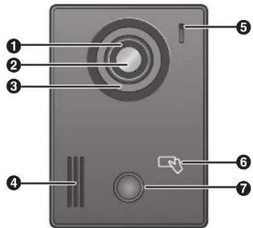
Front view
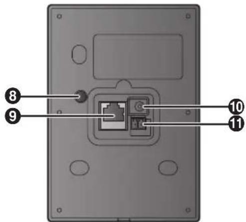
Rear view
① Lens cover
② Camera lens
③ Light
Used to illuminate the visitor's face or the area in front of the door station so that the visitor's face can be seen in the dark.
④ Speaker
⑤ Microphone
6 Card reader
Allows the door to be unlocked by using a card. The door station beeps if the card cannot unlock the door.
⑦ Call button and LED (blue)
Lights when idle and flashes when the call button is pressed or when a card is touched to the card reader.
8 Vandal proof button
See "Information about the vandal proof feature", Page 15
9 LAN connector
Used to connect the door station to the network.
10 DC IN connector
Used to connect the door station to a power supply unit (sold separately) when no PoE power supply is available.
⑪ R1/R2 connection terminals
Used to connect a relay box (sold separately) so that signals can be sent to an electric lock.
Installation cautions
Refer to the information found in “Important information”, Page 5 before installing the product.

CAUTION
- If the wiring passes outdoors, use a conduit and a surge protector.
- If the wiring passes underground, use a conduit, and do not make any connections underground.
- Install the product securely adhering to the instructions in this document to prevent it from falling off the wall. Avoid installing onto low-strength walls, such as gypsum board, ALC (autoclaved lightweight concrete), concrete block, or veneer (less than 18 mm thick) walls.
Information about power connection
There are 2 methods for powering the door station. Choose one or the other; do not use both methods.
– Using Power over Ethernet (PoE)
In this case, the door station and a PoE-compatible device (such as a PoE switch or power supply) are connected by a single LAN cable. The LAN cable carries both power and data.
- Using the VL-PS240 power supply unit (sold separately)
In this case, the power supply unit is hardwired to the power source, and connects to the door station using the included DC plug.
Power over Ethernet (PoE) connection
To power the door station using PoE, use a LAN cable to connect the door station and a PoE-compatible device (such as a PoE switch or power supply). See “Wire and cable specifications”, Page 17 for LAN cable specifications.
Installing the power supply unit (sold separately)
If the door station will not be powered via PoE, you must install a power supply unit.
Required items
– Power supply unit (VL-PS240; sold separately)
- DC plug (included)
– Cable binders (included with power supply unit)
- Screws (included with power supply unit)
- Wires for AC and DC connection (user supplied) See “Wire and cable specifications”, Page 17 for specifications.
- Soldering gun and solder, insulation sleeve (user supplied)
Installation location
- To device must be installed inside an electrical panel or cabinet.
- A readily accessible disconnect device shall be incorporated external to the equipment.
The external disconnect device must be certified, and have a creepage and clearance distance of 3 mm or more.
Installation methods
The following 2 methods can be used for installing the power supply unit.
– mounting on a DIN rail (user supplied)
- attaching directly to a wall
Connecting the AC wires, DC wires, and DC plug
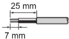
1 Strip the ends of the wires that connect to the power supply unit as shown below.
AC wires DC wires

2 Remove the cable cover screws and then remove the cable covers.

① Screws
② Cable covers
3 C onnect the AC wires to the AC IN terminals on the top of the power supply unit, and then connect the DC wires to the DC OUT terminals on the bottom of the power supply unit.
Top view (AC wires)

natural_image
Simple line drawing of a handheld electronic device with a vertical rod inserted into a box (no text or symbols)Bottom view (DC wires)

- For DC wires, the black wire is negative (-) and the other colour wire is positive (+). Note the colour of each DC wire and which terminal each wire should be connected to, and insert the DC wires as shown.

CAUTION
- insert the AC and DC wires firmly all the way into the terminals. If the wires are not inserted all the way, heat may be generated.
4 Tighten the terminal screws to secure the AC and DC wires (bare wire area) to the terminals, and then use the cable binders to secure the AC and DC wires (jacketed area) to
the cable binder holes on the top and bottom on the power supply unit.
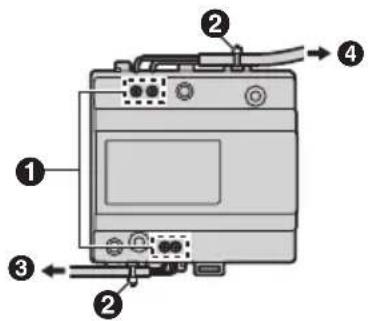
① Terminal screws
② Cable binders connected to cable binder holes
③ To door station
④ To AC power outlet
- Recommended torque:
- AC IN terminals: 0.5 N·m {5.1 kgf·cm}
- DC IN terminals: 0.45 N·m {4.6 kgf·cm}
5 Strip the remaining ends of the DC wires as shown.
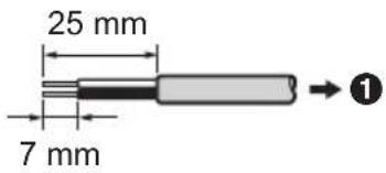
① To DC terminals of power supply unit
6 Solder the ends of the DC wires to the DC plug. Use insulation sleeves to insulate the wires.

① DC plug
② DC wires
③ Insulation sleeve
7 R eplace the cable covers and then securely fasten the cable cover screws.
Mounting on a DIN rail
Attach the power supply unit to the DIN rail so that the bottom hook is positioned at the bottom of the power supply unit.
1 Hang the top hooks of the power supply unit on the top of the DIN rail.
- At this point the power supply unit will be hanging from the DIN rail but will not be secure.
2 Pull the lever down, make sure the bottom of the power supply unit is flat against the DIN rail, and then release to lever.
- The bottom hook will slide up, securing the bottom of the power supply unit to the DIN rail.

① Top hooks
② Lever
③ Bottom hook
Attaching directly to a wall
Attach the power supply unit to the wall securely using the 2 mounting screws.

natural_image
Technical line drawing of a mechanical component with screws and mounting holes (no text or symbols)Installing the door station
Required items
- Mounting base (included)
- Screws (included)
- 2-pin terminal block (included)
– LAN cable (user supplied)
See "Wire and cable specifications", Page 17 for specifications.
- Wires that connect the door station to relay box and electric lock (user supplied)
See "Wire and cable specifications", Page 17 for specifications.
– Water-resistant sealant (user supplied)
Optional items
- Relay box (VL-RLY1; sold separately)
Installation location
- Do not install the product in the following locations. There may be a risk of malfunction or communication disturbances.
- Places where vibration, impact, or echoing occurs.
- Places near a high concentration of dust, hydrogen sulphide, ammonia, sulphur, or noxious fumes.
- Places where there is excessive smoke, dust, and high temperature.
- Places exposed to direct sunlight.
- Places where most of the background is the sky.
- Places where the background is a white wall, and direct sunlight will reflect off it.
- Install the product away from electronic appliances such as TVs, radios, personal computers, air conditioners, boiler control panels with intercom, home security equipment, wireless devices, or digital cordless phones.
- Install the door station at least 5 m away from the room monitor.
- Dust protection/water protection is IP54. Only when installation work specified in this document is properly performed and appropriate water protection treatment is performed.
- Make sure the rear of the product is not subject to water.
- Depending on the installation location, condensation may form on the product's lens cover. This may cause images to become obscured. Condensation will dissipate as the temperature rises.
Installation position of the door station and camera range
Refer to the following examples and confirm the area viewable by the camera. In each illustration, the viewable area is indicated by "①" and the centre of the camera lens is indicated by "②".
Installed on vertical wall, side view

Top view

Note:
- To measurements and angles shown here are for reference purposes and may vary depending on the environment.
- Install the door station so that the door station is not exposed to strong light. If strong light shines on the door station, the visitor's face may not be distinguishable.
Installation
Important:
- When existing wiring (such as chime wires) is used:
- It may contain AC voltage that may cause electric shock and/or damage the product.
– Never use the following types of wiring. Consult a qualified technician/dealer.

- See "Wire and cable specifications", Page 17 for information about wiring materials.
1 Remove the screw, and then remove the mounting base.
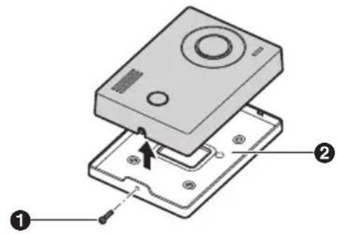
1 Screw
② Mounting base
2 A tach the mounting base to the wall securely using the mounting screws.
- After securing the mounting base to the wall, caulk the top and sides of the mounting base with water-resistant sealant. Do not caulk the bottom side.
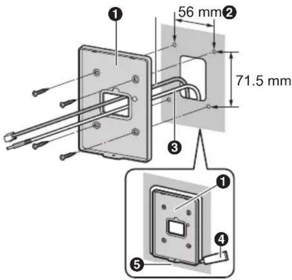
1 Mounting base
② LAN cable
③ DC cable from power supply unit
4 Area aulked with water-resistant sealant
⑤ Area not to be caulked
3 C onnect the wires and cables to the door station.
- See "Connecting the wires and cables", Page 14.
4 Attach the door station to the mounting base, and then secure the door station to the mounting base using the screw.
Connecting the wires and cables
1 Co nnect the LAN cable to the LAN connector.
2 Optional
If you are using a power supply unit to power the door station, connect the DC plug to the DC IN connector.
- See “Installing the power supply unit (sold separately)”, Page 10 for information about installing the power supply unit.
3 Optional
If you are using a relay box to connect an electric lock to the door station, insert the wires from the relay box into the 2-pin terminal block, tighten the terminal block screws, and then attach the 2-pin terminal block to connection terminals R1 and R2.
- Make sure the wires are inserted fully into the terminal block and that the terminal block screws are tight enough to prevent the wires from pulling out.
- Make sure the 2-pin terminal block snaps into place and is securely connected to connection terminals R1 and R2.
- See "Installing the relay box (sold separately)", Page 15 for information about installing the relay box.
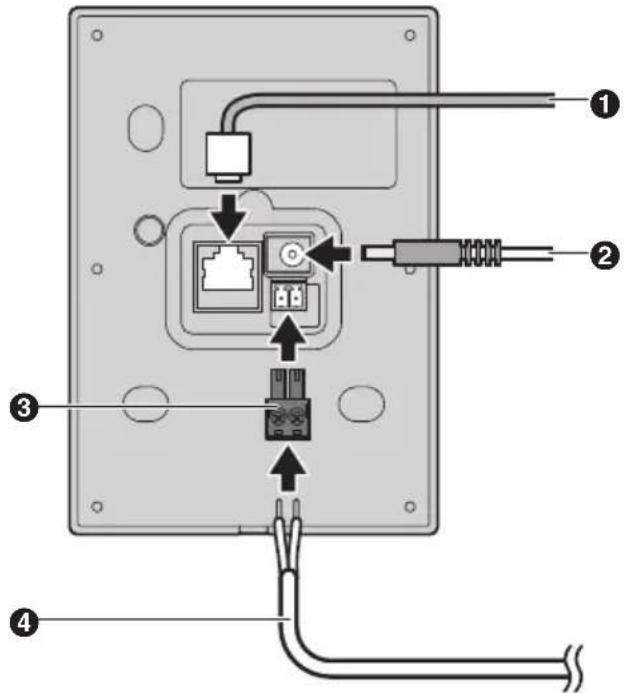
① LAN cable
② DC plug from power supply unit
③ 2-pin terminal block
④ Wires from relay box
Note:
- Refer to the documentation of the compatible room monitor for wiring schematics.
- Refer to “Wire and cable specifications”, Page 17 for information on the type and length of wires that can be used.
Information about the vandal proof feature
When the door station is installed using the mounting base, the mounting base presses against the vandal proof button and holds the button down as long at the door station is attached to the mounting base. If there is an attempt to remove the door station from the mounting base, the vandal proof button is released and the vandal proof feature sounds an alert for 3 minutes.
Note:
- If this alert is triggered accidentally during installation, or to avoid false detections when performing maintenance, disconnect the door station from the power supply by disconnecting the DC plug or by cutting the power to the power supply unit.
- To avoid false detections during installation, the vandal proof feature cannot be triggered unless the vandal proof button has been pressed down continuously for 3 minutes.
Installing the relay box (sold separately)
A relay box must be used when connecting an electric lock to the door station.
Required items
– Relay box (VL-RLY1; sold separately)
– Cable binders (included with relay box)
– Screws (included with relay box)
– Electric lock (user supplied)
- Wires connections (user supplied)
See “Wire and cable specifications”, Page 17 for specifications.
Connecting the wires
1 St rip the ends of the wires that connect to the relay box as shown below.
Door station wires Electric lock wires

2 R remove the cable cover screw and then remove the cable cover.

① Screw
② Cable cover
3 Connect the electric lock wires to connection terminals S1 and S2 on the top of the relay box.

① Terminals
4 T ighten the terminal screws to secure the electric lock wires to connection terminals S1 and S2, and then use the cable binder to secure the electric lock wires (jacketed part) to the cable binder hole.

① Cable binder connected to cable binder hole
② To electric lock
③ Terminal screws (S1/S2)
- Recommended torque for terminal screw: 0.45 N·m {4.6 kgf·cm}
5 Connect the wires from the door station by pressing the wire release button with a pointed object such as a screwdriver while inserting the wire into connection terminals R1 and R2. (To disconnect a wire, press the button while pulling it out.)

① Wire release buttons
② Connection terminals (R1/R2)
③ To door station
- Note that connection terminal R3 is not used.
6 Strip the remaining ends of the door station wires as shown station.

① To terminals of relay box
7 Replace the cable cover and then securely fasten the cable cover screw.
Mounting on a DIN rail or wall
For information on how to mount the relay box on DIN rail or a wall, refer to descriptions used for the power supply unit in "Mounting on a DIN rail", Page 12 and "Attaching directly to a wall", Page 12.
Wire and cable specifications
| Wiring run Specifications Max. length | ||||
| Door station ↔ Switching hub | Cat-5e or higher, stranded, twisted pair, straight | 100 m | ||
| Power supply unit ↔ Door station | 0.65 mm (22 AWG) approx. 10 m | |||
| 2 mm (12 AWG) approx. 20 m | ||||
| Power supply unit ↔ AC power source | 1.2 mm (17 AWG) | No requirement | ||
| 2 mm (12 AWG) | ||||
| Door station ↔ Relay box | 0.5 mm (24 AWG) According to specification of connected device. | |||
| 1.2 mm (17 AWG) | ||||
| Relay box ↔ Electric lock | 0.5 mm (24 AWG) According to specification of connected device. | |||
| 1.2 mm (17 AWG) | ||||
Note the following when selecting wiring
- Foall wiring (except network wiring), use 2-conductor (solid copper) wiring with a PE (polyethylene)-insulated PVC jacket.
Mid-capacitance, non-shielded wiring is recommended.
- A certified power supply wiring has to be used with this equipment. The relevant national installation and/or equipment regulations shall be considered. A certified power supply wiring not lighter than ordinary polyvinyl chloride flexible wiring according to IEC 60227 shall be used.
- When connecting an electric lock, select a device that meets the following guidelines. Electric lock connection terminal (Relay box: S1/S2):
– N/O dry closure contact
- 12 V AC/DC, less than 1 A
Specifications
Door station (VL-VN1500)
| Power source When using PoE: Class 2, IEEE 802.3afWhen using power supply unit (VL-PS240): 24 V DC, 0.6 A | |
| Power consumption | Standby: approx. 2.5 W for PoE, 2.6 W for VL-PS240During operation: approx. 5.1 W for PoE, 6.3 W for VL-PS240 |
| Dimensions (mm) (height × width × depth) | Approx. 141×100×28.5(excluding protruding sections) |
| Mass (weight) Approx. 250 g | |
| Operating environment | Ambient temperature: approx. -10 °C to +55 °CRelative humidity (non-condensing): up to 90 % |
| Installation method | Wall mount (mounting base supplied) |
| Image sensor 1/3-inch CMOS sensor (approx. 1.3M pixels) | |
| Viewing angle Horizontally: approx. 113°Vertically: approx. 69° | |
| Minimum illuminance required | 1 lx(within approx. 50 cm from the camera lens) |
| Lighting method LED lights | |
| IP rating | IP54*1 |
| Card reader (RFID) | ISO/IEC 14443 Type A (MIFARE®)(Frequency: 13.56 MHz; RF transmission power: 42 dBμA/m (max.) @ 10 m) |
| Video format H.264 codec | |
| Audio format G.711 codec | |
| Network interface | Ethernet II (DIX) |
| Network protocol | T CP/IP, UDP |
| Communication mode | Speed, Duplex AUTO (10BASE-T/100BASE-TX, FULL/HALF) (Auto negotiation) |
*1 Water resistance is only assured if the product is installed correctly according to the instructions, and appropriate water protection measures are taken.
Power supply unit (VL-PS240, sold separately) The power supply unit is for indoor use only.
| Power source Input: 220-240 V AC, 0.2 A,50/60 HzOutput: 24 V DC, 0.6 A | |
| Dimensions(mm) (height ×width × depth) | Approx. 116×100×54(excluding protruding sections) |
| Mass (weight) Approx. 230 g | |
| Operating environment | Ambient temperature: approx.0 °C to +50 °CRelative humidity(non-condensing): up to 90 % |
| Installation method | Attach to DIN railWall mount (using included screws) |
Relay box (VL-RLY1, sold separately)
| Power source P | Power supplied by the door station |
| Dimensions (mm) (height × width × depth) | Approx. 92×78×38 (excluding protruding sections) |
| Mass (weight) A | Approx. 130 g |
| Operating environment | Ambient temperature: approx. 0 °C to +40 °CRelative humidity (non-condensing): up to 90 % |
| Installation method | Attach to DIN railWall mount (using included screws) |
Cleaning
Wipe the product with a soft, dry cloth.
For excessive dirt, wipe the product with a slightly damp cloth.
Important:
- Do not use any cleaning products that contain alcohol, polish powder, powder soap, benzine, thinner, wax, petroleum, or boiling water. Also do not spray the product with insecticide, glass cleaner, or hair spray. This may cause a change in colour or quality of the product.
Open source software notice
Parts of this product use open source software supplied based on the relevant conditions of the Free Software Foundation's GPL and/or LGPL and other conditions. Please read all licence information and copyright notices related to the open source software used by this product. This information is available at the following web page: http://panasonic.net/pcc/support/intercom/vn1900 At least three (3) years from delivery of this product, Panasonic Corporation will give to any third party who contacts us at the contact information provided below, for a charge of no more than the cost of physically distributing source code, a complete machine-readable copy of the corresponding source code and the copyright notices covered under the GPL and the LGPL. Please note that software licensed under the GPL and the LGPL is not under warranty. http://panasonic.net/pcc/support/intercom/vn1900
Panasonic Corporation
1006, Oaza Kadoma, Kadoma-shi, Osaka 571-8501, Japan
http://www.panasonic.com
© Panasonic Corporation 2017
- Installation and Operating Instructions
- Note to the installer
- Introduction
- Important information
- Preparation
- Installation
- Other information
- System overview
- Main features
- Camera features
- Other features
- Included items
- Optional items
- About this document
- Terms and illustrations
- Trademarks
- Important safety information
- Note:
- WARNING
- Preventing fire, electric shock and short circuits
- CAUTION
- Preventing accidents, injuries, and property damage
- Important safety instructions
- SAVE THESE INSTRUCTIONS
- Privacy and rights of portrait
- Data security
- What is user information?
- Data security guidelines
- Disclaimer
- Other important information
- General information
- For business users in the European Union
- Information on Disposal in other Countries outside the European Union
- Note for the battery symbol
- For India only
- Declaration of Conformity with the requirements of the E-Waste (Management) Rules
- Disposal information
- For Europe
- Declaration of Conformity
- Contact to Authorised Representative:
- Ecodesign information
- Device diagrams
- Installation cautions
- Information about power connection
- Power over Ethernet (PoE) connection
- Installing the power supply unit (sold separately)
- Required items
- Installation location
- Installation methods
- Connecting the AC wires, DC wires, and DC plug
- Mounting on a DIN rail
- Attaching directly to a wall
- Installing the door station
- Installation position of the door station and camera range
- Important:
- Connecting the wires and cables
- Information about the vandal proof feature
- Installing the relay box (sold separately)
- Connecting the wires
- Mounting on a DIN rail or wall
- Note the following when selecting wiring
- Specifications
- Cleaning
- Open source software notice
- Panasonic Corporation
Brand : PANASONIC
Model : VL-VN1500SX
Category : Doorbell