SR-T 102 - Camera KONICA MINOLTA - Free user manual and instructions
Find the device manual for free SR-T 102 KONICA MINOLTA in PDF.

User questions about SR-T 102 KONICA MINOLTA
0 question about this device. Answer the ones you know or ask your own.
Ask a new question about this device
Download the instructions for your Camera in PDF format for free! Find your manual SR-T 102 - KONICA MINOLTA and take your electronic device back in hand. On this page are published all the documents necessary for the use of your device. SR-T 102 by KONICA MINOLTA.
USER MANUAL SR-T 102 KONICA MINOLTA
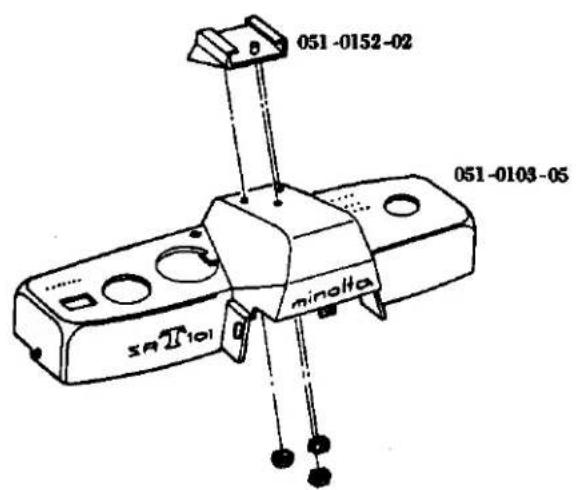
SRTseries Black Body Parts List
051 Top cover & Accessory shoe
text_image
051-0152-02 051-0103-05 minolta SAII101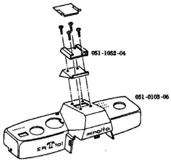
text_image
051-1052-04 051-0103-06 minolta SR T101051 Winding lever
051-0315-01

natural_image
Simple line drawing of a mechanical clamp or clip (no text or symbols)051-0315-02

natural_image
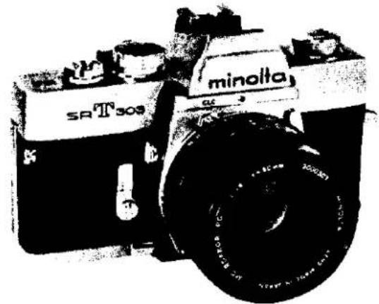
Line drawing of a mechanical tool or clamp (no text or symbols)SR-T 303 (CODE NO. 059)
natural_image
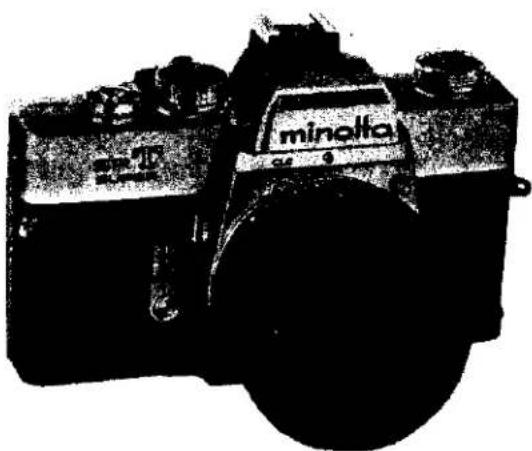
Black-and-white photo of a vintage minolta SR T309 camera with visible lens and body (no text or symbols on body)SR-T 102 (CODE NO. 064)

natural_image
Black-and-white photo of a vintage minolta SR T102 diesel locomotor with visible branding and wheels (no text beyond branding)SR-T SUPER (CODE NO. 093)
text_image
minolta 54-0FORWORD
We have issued this service manual to assist you in carrying out complete repair service. It gives your thorough description of the services which are essential to this Minolta's product, and thus enables you to be your own consultant in maintaining quality and precision.
This SR-T 303, SR-T 102, SR-T super service manual consists or five parts, viz., specifications, parts list, disassembly instructions, Reassembly instructions and adjustment instructions. For easy reference, each subject has an index sheet.
How to use the Service Manual
Specifications: This gives various product particulars item by item.
It serves as technical reference material when inquiries are received from domestic and overseas customers.
Parts list:
1) This is composed of a table of contents, disassembled diagrams, parts numbers, parts names, and quantity of parts.
2) It is arranged with disassembled or exploded drawings on the left page and the parts numbers, parts names and quantity of parts on the right page.
3) On each page, the disassembled parts bear their respective parts numbers.
4) Parts which are not supplied are indicated by "NO SUPPLY" in place of parts numbers in the disassembled diagrams.
5) "See Page……" appearing in the disassembled diagrams indicates that the blocks concerned are shown disassembled on cited page(s).
6) This parts list manual available use three kind models for SR-T 303 (059), SR-T 102 (064) and SR-T Super (093), also use SR-T 101 (031). It appearing as before the main product codenumber for parts number, be common to the parts list manual.
7) Make-up of the Parts Code: The parts code is indicated by ten number spaces as illustrated below:
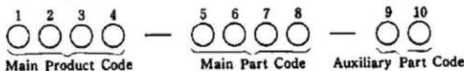
text_image
1 2 3 4 Main Product Code — 5 6 7 8 Main Part Code — 9 10 Auxiliary Part Code8) Indication of Parts Numbers:
A. Coupled Parts Numbers: A main part code with 0 in the fifth space indicates coupled parts.
Example :
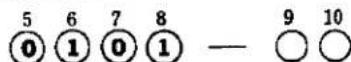
B. Simple Parts Numbers: A main part code with 1 to 9 in the fifth space indicates simple parts.
Example :
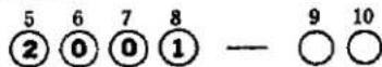
C. Auxiliary Part Code Numbers: The 9th and 10th spaces are for auxiliary code numbers indicating how often the parts have been altered.
Example :

D. Coupled parts which can also be supplied as simple parts are indicated with light-face-type figures as shown below:
Example :
E. Special care in observing the related footnote is necessary with reference to parts having a ★ Symbol in front of their numbers.
9) Revised pages will be issued indicating the number of times it has been revised by using the numbers 1, 2, 3 and so on following a hyphen after the page number, as shown in the following example.
When revision are made on page 1, the first revision will be indicated by 1-1 the second by 1-2, the by 1-3 and so on.
Disassembly
instructions: This is an easy-to-understand guide that gives clear, step-by-step instructions so that even beginners can disassemble the HI-MATC F.
Reassembly
instructions: This further an easy-to-understand guide gives similar clear, step-by-step instructions for reassembling this product.
Adjustment
instructions: This is a guide to the main points of adjustments to be accomplished after repair of this camera.
MINOLTA SR-T 303
MINOLTA SR-T 102
MINOLTA SR-T SUPER
LENS
MC ROKKOR-PG 58mm F1.2
Construction: 7 elements in 5 groups
Angle of View: 46°
Angle of view: 40°
Diaphragm scale: 1.2 2 2.8 4 5.6 8 11 16
Focusing: Direct helicoid focusing
Min. focus distance: 0.6 m
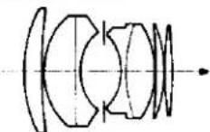
MC ROKKOR-PG 50 mm F1.4
Construction: 7 elements in 5 groups
Angle of view: 46°
Diaphragm scale: 1.4 2 2.8 4 5.6 8 11 16
Focusing: Direct helicoid focusing
Min. focus distance: 0.5 m
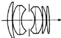
MC ROKKOR-PF 50 mm F1.7
Construction: 6 elements in 5 groups
Angle of view: 46°
Diaphragm scale: 1.7 2 2.8 4 5.6 8 11 16
Focusing: Direct helicoid focusing
Min. focus distance: 0.5 m
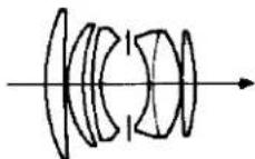
Lens type: Modified gauss type
Coating: Achromatic coating
Diaphragm: Fully automatic
Lens mount: SR Bayonet mount
SHUTTER
Focal plane shutter
1650 1500 and 1/1000 sec.
Dial: Single, non-spring, equal space, click stop dial.
Sync. contact: FP (all speeds) and X (up to 160 sec.)
FP, X change lever install
Self-timer: Time adjustable, 10 sec. maximum-delay
FILM ADVANCE
Winding method:
Lever type, quick advance winding with shutter cocking and
double exposure prevention.
Single or several strokes with
clearance to wind 20°.
Winding angle: 150°
Film counter; Automatic resetting counter showing exposed fram number.
Film rewinding: Rapid rewinding with crank.
Frame size: 24×36 mm
Film: Standard 35 mm film, 20 or 36 exposures.
Double exposure: Double exposure install by rewind-
ing button.
VIEW FINDER
Real image finder through the fixed, eye-level pentaprism. Exposure control needles (followr type), shutter speed scale and diaphragm scale are visible in finder.
Focusing glass: Split image, fine microprism and fresnel lens.
Image magnification: Life size image view with 50mm
lens on infinity.
MIRROR
Over-sized quick return mirror with lock-up device.
EXPOSURE METER
Thru-the-lens meter
Exposure meter: Contrast light compensator (C.L.C)
CdS meter, two cells on the penta-
prism.
Measurement: Measuring at full-aperture opening
coupled to shutter speed, aperture
and film speed setting.
Controlling: Follower needle system viewing in
the finder.
Working range: EV 3 to EV 17 on 100 ASA film.
Diaphragm button: Depth-of-field preview button
for MC (Meter coupling) Rokkor
lenses. Measuring (stopped-down)
button for other automatic Rokkor
lenses.
Film speed range: ASA 6 \~ 6400
DIN 9 \~ 39
ASA setting: On shutter speed dial built in ASA-
DIN converting scale on the camera
back.
Battery: Mallory RM-625R or its equivalent.
Switch: ON, OFF and battery check switch on the
f the camera. Battery check mark
finder.
OTHERS
Built in direct contact for "HOT SHOE" on accessory
sho
FEATURES
-
Better Through-the-Lens Exposure System
-
Exposure readings are taken with the lens at full aperture for greatest metering accuracy and best viewing and focusing.
○ Since only the light to strike the film is measured, there is no need to compensate for filters, greater-than-normal lens extension, etc.
The exclusive CLC metering system combines advantages of spot and averaging types to yield optimum exposure even in high-contrast lighting situations. -
"Information-Center" Viewfinder
○ Meter and follower needles in the viewfinder show correct exposure setting at a glance.
- Both shutter speed and F-number set are visible without taking your eye from the finder.
- Focusing virtually any kind of subject is facilitated by the new focusing aid that employs a split-image spot and a microprism band.
- Multiple-Exposure Capability
Creative possibilities are greatly expanded by these camera's ability to make multiple exposures simply and positively.
- Direct-Contact "Hot Shoe"
This accepts either cordless units or conventional ones with cords.
- World-Renowned Rokkor Lenses
MC Rokkor Lenses permit full-aperture TTL operation, while any other interchangeable Rokkor ever made can be used with the step-down method. Either way you benefit from top Rokkor quality, computer design, and exclusive Achromatic coating.
- Complets System Accessories
A full line of quality Minolta and Leitz accessories makes for maximum versatility with the 303, 102, SUPER.
SIZE AND WEIGHT (With F 1.4 50 mm)
5 9/4" (W) × 3 1/4" (D) × 3 9/4" (H)
145 × 89 × 95 mm
35 oz. (1015 g)
ミノルタ SR-T 303
ミノルタ SR·T 102
ミノルタ SR-T SUPER
レンズ
For adjustment (調整用)
For adjustment (調整用)
For adjustment (調整用)
For adjustment (調整用)
[Comparative Parts List for 059 series and 2002 series]
(Comparative Parts List for 031 series and 2003 series)
A. Top Cover 1
B. Bottom Cover 1
C. Accessory Shoe Disassembly 3
D. Finder and Meter Block Disassembly 5
E. Prism Holder Disassembly 7
F. Front Base Plate 9
G. Self-Governor and Mirror Box 11
H. Needle Following Base Plate 13
1. Needle Following Base Plate Disassembly.... 15
J. Aperture Reducing Plate, Resistor Base Plate and Battely Case 17
K. Slow-Governor and Shutter Base Plate-A 19
L. Shutter Base Plate-A Disassembly.... 21
M. Winding Base Plate 23
N. Winding Base Plate Disassembly 25
O.Shutter Base Plate-B 27
P. Spool and Double Exposure Device 29
Q. Sprocket 31
R.Shutter Curtain 33
S. Others Disassembly 35
分解編
A. Top Cover Removal
- Remove 2 pieces of 9613-1720-04 located on the front name plate and remove 0108.
- Pull out the rewinding knob so as to open the back cover and insert the fulcrum point of a pincette into a slot in the rewinding shaft so as to unscrew and take out the rewinding knob.
- Remove 3309 using the special tool (031-3353-77).
- Remove 3013 using the special tool (031-3013-77), and take out 3009, 9568 or 9569, and 0315.
- Remove 9615-1725-04 of the speed dial so as to take out 2002, 0252, 2005 and 2001.
- Remove 2 pieces of 9176.
- Remove 3 pieces of 9617-1730-04, so as to pull out 0104 from the camera body.
Caution: 3012, 3019 and 3029 in the camera body are apt to be taken off so that care should be taken not to loose them.
B. Bottom Cover Removal
- Remove 2 pieces of 9615-1730-04, so as to pull out 0105 from the camera body.
A. 上カバー取外し要領
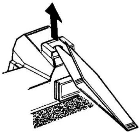
C. Accessory Shoe Disassembly
- Remove the top cover. (See Page. 1)
- Life the front part of 1053 in the accessory shoe using a forceps as indicated in Fig. 3, insert the forceps as shown in Fig. 4, and remove 1053 by lifting in with a lever action.
- Remove 2 pieces each of 9613-1777-01 and 9613-1747-01, and take out 0151, 1052.
- Remove 2273.
- Remove 9179, 2271, 9455, 0270, 1051 and 2273 in that order. Do not lose 2273 as it is easily removal.
c. アクセサリーシュー分解要領
natural_image
Technical line drawing of a mechanical device with an arrow pointing to a component (no text or symbols present)Fig. 4
natural_image
Technical line drawing of a mechanical lever mechanism with an upward arrow indicating motion (no text or symbols present)5
D. Finder and Meter Block Disassembly
- Remove the top cover. (See Page 1)
- Unsolder 4 lead wires. (See Fig. 6)
- Remove 9451 provided on the needle following base plate using a special tool (1031-9451-77), and take out 4056. Remove 4057 set on 0454, take out 0454 and take off 4058.
- Remove 2 pieces of 9612-1725-02, 0538.
- Remove 2 pieces of 9612-1725-02, 0535.
- Release the TV coupling string (5053) fitted into the slot in the index string outer tube (5056), and take out the shutter speed index (5057) attached to the index coupling string position adjuster (2163) and take out the coupling string (5053). Take out 5057 from 5053.
- Disengage and take out the AV coupling string (4080), engaged in the slot of the time value pulley (4068). Disengage and locate it at lateral side of the front frame.
- Disengage and take out the TV coupling string (5053), engaged in the slot of the shutter base plate-A. Disengage and locate it at back side of the camera body.
- Remove 3 pieces of 9132, take out the finder and meter block.
- Remove 2 pieces of 9118, 0227, 0538 and 5024.
- Take out 4073 and remove 9154 with a special tool (031-9154-79). Remove 9611-1725-01 and 4391.
E. Prism Holder Disassembly
- Remove the finder and meter block. (See Page 5)
- Remove 4 pieces of 9615-1720-02 from the bottom of 5017 and take off 0525. Then take 5065, 5067, 5804, 5003 and 5805 out of 5017.
- Remove 9611-1415-01, 5055, 5054, and 5056.
E. ペンタプリズムホルダー分解要領
F. Front Base Plate Removal
- Remove the finder and meter block. (See Page 5)
- Remove 9165, 1039 and 1038 from front side of the camera body.
- Strip off 1015.
- Shut the camera body to the state in which the shutter has been released, then remove 4 pieces of 9615-2040-02 and 9615-2040-02, so as to take out front base plate.
Caution: Pay attention to 1015 as 1021 is attached to it.
F. 前枠取外し要領
G. Self Governor and Mirror Box Removal
- Remove the front base plate. (See Page 9)
- Remove 3 pieces of 9615-1735-02, 2491 from the front base plate.
- Remove 1075.
- Remove 4 pieces of 9611-1732-04, 1010, and then take out from the slot of the back of 0163, 4080 so as to take out 0163.
- Take out 1064 with care so that the washer may not be deformed.
- Remove 2 pieces of 9611-1730-04, 1073 and 1006.
- Remove 4 pieces of 9611-2032-01, and dismount the mirror box from the front base plate.
H. Needle Following Base Plate Removal
- Remove the top cover. (See Page 1)
- Attach to the rewinding shaft the special tool (031-0013-79) take out 4080 which is fitted into the slot of 4068 and disengage the same so as to locate it at the lateral side of the front frame.
- Take out 4081 which is fitted into the slot of 4082 and also disconnect the engagement with the slot of the film speed ring so as to take out 4081.
- Unsolder the lead wires (Yellow and Blue) of 0451, and lead wires (Red and Black) from the front side of the camera body.
- Remove 9611-1740-01, 9611-1415-02, and 0451.
- Remove 9451 and 4056. Also disconnect the engagement of 4057 with 0454 and then pull out 0454 so that 4057 may be taken out.
- Remove 2 pieces of 9611-1730-01 of the needle following base plate and also 3 pieces of 9611-1730-01 from the opening of the base plate so that the needle following base plate.
H. 追針台板取外し要領
1. Needle Following Base Plate Disassembly
- Remove the needle following base plate. (See Page 13)
- Remove 4060, 4068 set, and 9562. Remove 4059 using the special tool (031-4059-77) so as take out 0470, 0469 and 9566.
- Remove 2 pieces of 9605-1417-01 and 4051 and remove 4067, 4078 and 9563. Also, remove 3308, 3310 and 3304.
- Remove 9601-1412-02 from 4067, then take out 4078.
1. 追針台板分解要領
J. Aperture Reducing Base Plate, Resistor Base Plate and Battery Case Removal
- Remove the front base plate. (See Page 9)
- Attach to the rewinding seat so as to take out the bottom cover. (See Page 1)
- Remove the bottom of the body and remove 3065 and 2580 from 9008. Then remove 9008. Loosen 2582 and 9611-2035-02 to remove 0251 from the body. At it time, remove 3073 from 0357 of the body. Also, remove 9006, 0357 and 3075.
- Unsolder the lead wires from the resistor base plate. (See Fig. 13)
- Remove 2 pieces of 9612-2045-02, 1112 and resistor base plate.
- Remove 3 pieces of 9612-1750-01, and battery case.
- Remove 9006, 0361, 3075 and 0357 connected with 0361.
K. Slow Governor and Shutter Base plate-A Removal
- Remove the top cover. (See Page 1)
- Remove 2 pieces of 9611-1725-01, 2391.
- Remove 4081. (See Page 13 H. Needle Following Base Plate Removal)
- Remove 5053. (See Page 5 D. Finder and Meter Block Disassembly)
- Take out the lead wires (White and Brown) from 2263, remove 9612-1740-01 and 2263, and also remove another 9612-1740-01.
- Remove 2 pieces of 9611-1725-01 and 0455. Also, remove 9156, 9153 and 0216 to take out the shutter base plate-A.
L. Shutter Base Plate-A Disassembly
- Remove the shutter base plate-A (See Page 19)
- Remove 2023.
- Remove 2 pieces of 9611-1415-02 and 2033. Also, remove 9421, 2020, 9793-1838-20, 0221 and 0224 from the bottom of 2033.
- Remove 9720-0080-00 from 0224 and 0226, 9790-1322-40 or 9791-1322-40 or 9799-1322-40 from 0224.
- Remove 9720-0080-00, 9792-1328-40, 2031, 2028 and 0229.
- Remove 9611-1725-01, 2 pieces of 9612-1425-02, 2007, 0254 and 2010.
- Remove 9147 and take the remaining blocks out of 0220.
- Remove 2 pieces of 9611-1730-02 and take 2015, 2016, 0213 and 2017 out of 2011.
L. シャッター台板A分解要領
M. Winding Base Plate Removal
- Remove the top cover. (See Page 1)
- Remove the slow-governor. (See Page 19)
- Take out the lead wires (White and Brown) provided in the curve of 0359, and remove 2 pieces of 9617-1735-01, 0359 and 9107.
- Remove 2 pieces of 9612-1720-01 and 3068.
- Remove 2 pieces of 9612-2030-01 and take out winding base plate from the camera body.
M. 卷上台板取外し要領
N. Winding Base Plate Disassembly
- Remove the spring from 0350.
- Remove 9110, 3402, 0350 and 9792-2645-40.
- To remove 3027, loosen 9108 and 9602-1725-02 holding it.
- Remove 3015 (reverse screw), 3017, 3022, 3076, 3077, 3078 and 3001.
- Remove 9720-0190-00, 9792-2645-40, 3412 and 0306.
- Remove 3413 and 3414.
N. 卷上げ台板分解要領
O. Shutter Base Plate-B Removal
- Remove front base plate. (See Page 9)
- Remove slow-governor and shutter base plate-A. (See Page 19)
- Remove winding base plate. (See Page 23)
- Remove bottom cover. (See Page 1)
- Remove battery case. (See Page 17)
- Remove 2 pieces of 9611-1730-02 at the front of the body, remove 2213 and 0221 to draw them toward the front of the body.
- Insert a screw-driver through the hole in the body under the battery case to remove 2113. Also, remove 2112, 9793-3258-20 and 2110, pull 9223 and take out 2109, 2111, 2108 and 9795-3248-20.
- Remove 9602-1430-01, 9117, 0223, 2082 and 0247.
- Remove 9720-0120-00, 9792-2038-40, 0298 and 0293.
- Put a minus screw-driver in 2051 to hold it in place, remove 9117 and unscrew 2051. Put a minus screw-driver in 2052 to hold it in place, remove 9117 and unscrew 2052.
- Remove 9615-1735-02, 9109, 5033 and 9111, the latter two of which are located at the bottom. By lifting 0250, remove 2053, 2054 and take off 0250.
Caution: When removing 0250, check that an adjusting washer is attached to the back of 0250. - Remove 9720-0120-00 provided under the shutter base plate-B and remove 0240, 9790-2550-40 or 9791-2550-40 from the shutter base plate-B.
0. シャッター台板B取外し要領
P. Spool and Double Exposure Device Removal
- Remove slow-governor. (See Page 19)
- Remove winding base plate. (See Page 23)
- Remove bottom cover. (See Page 1)
- Remove 9617-1750-01, and 3002.
- Remove 9617-1735-01 from the hole in the spool by turning the spool clockwise and draw out 3031. Then remove 3037, 3039 and 3032 from the body.
- Remove 3086.
- Remove 2 pieces of 9020, 3086, 3089, 0385 and 0381.
- Remove 3 pieces of 9611-1735-01, 0345 and 3040.
P. スプール、二重露光装置取外し要領
- Remove Shutter base plate-B. (See Page 27)
- Remove 2 pieces of 9103 from 0235 and take 0235 off the body.
- Remove 9006 from the bottom of the body, take 0361 and 3075 out of the body, and remove 3067 from 3066, then 9004 and finally 3066.
- Open the back cover and remove 3053 (reverse screw) from the bottom of the body while pressing the sprocket. Then take out 3054 and 3051.
- Remove 3004 and 0393 from the body, remove 9720-0150-00 from the front of the body and lift 0389 up after freeing the stop lever at the bottom of the body.
- Remove 2 pieces of 9615-1425-02 from the top of the body and take out 0348 and 3049. Also, remove 3 pieces of 9615-1425-02 from the bottom of the body and take off 3050 to draw 3046 out of the body.
Q. スプロケット取外し要領
R. Shutter Curtain Removal!
-
Remove bottom cover. (See Page 1)
-
Remove front base plate. (See Page 9)
-
Remove Shutter base plate-B. (See Page 27)
-
Remove 9611-1720-02, 9615-1425-02 and 0191 from the front of the body.
-
Take out the bottom of the body and unsolder the lead wires (two yellows, red, green and resistor)
-
Remove 2523, 2074 of 0297 and 2075 and unscrew 2 pieces of 2073. (Reverse screws)
-
Remove 2 pieces of 9612-1725-02 and 0297. After drawing out the spring shaft of the first and second curtains, remove the first and second curtains.
R. シャッター幕取外し要領
S. Disassembly for Others
- Remove bottom cover. (See Page 1)
- Remove front base plate. (See Page 9)
- Remove needle following base Plate. (See Page 15)
- Remove spool. (See Page 29)
- Remove sprocket. (See Page 31)
- Remove 9171, 2513 and 9403.
- Remove 9054 and 2523.
- Remove 2424, 9170, 2508, 9406 and 2524.
- Remove 2522, 9053, 9613-2350-01, 1013, 2569 and 4256.
- Remove 9104, 0259, 2511 and 0256.
- Remove 3056, 9004, 3055 and 3056.
- Remove 9139, 9408, 3059, 9791-3142-40 and 0398.
- Remove 3070 and 3058 and take off 9121, 3070, 3069, 3071 or 3072, 0395, 9793-2250-20 and 3058.
- Remove 9005 and 2521.
5. その他分解要領
C. Accessory Shoe Assembly 3
D. Finder and Meter Block Assembly 5
E. Prism Holder Assembly 11
F. Self-Governor and Mirror Box 13
G. Front Base Plate.... 17
H. Needle Following Base Plate Assembly 19
I. Needle Following Base Plate 21
J. Aperture Reducing Base Plate, Resistor Base Plate and Battery Case 27
K. Shutter Base Plate-A Assembly 29
L. Slow Governor and Shutter Base Plate-A 31
M. Winding Base Plate Assembly 33
N. Winding Base Plate 35
O. Spool and Double Exposure Device 37
P.Shutter Base Plate-B 39
Q. Sprocket 45
R.Shutter Curtain 47
S. Others Assembly 49
組 立 編
A. 上カバー 1
B. 下カバー 1
C. アクセサリーシュー組立て 3
A. Top Cover Mounting
Check points before mounting;
* Check if the lead wires of the camera body are kept in order.
* Check if the eye-piece lens is free from dust or stain.
-
Clean the counter window of 0103, set 0103 on the body, and tighten the three 9617-1730-04s.
-
Tighten 3309 against the rewind shaft bearing by using the special tool (031-3353-77), and fasten the rewinding knob to the rewind shaft.
-
Mount 0315 on the winding lever holder, place 9568 or 9569 and 3009 on the assembly, and tighten 3013 using the special tool (031-3013-77).
-
Insert into the speed dial ring (2001) the sensitive plate spring (2005), on which are located the sensitive plate seat (0252) and the speed dial scale plate (2002). Hold the sensitive plate seat (0252) and the scale plate (2002) from the upper side there of and insert the long bended or folded portion of the seat (0252) into the elongated slot of the film speed ring of the shutter base plate-A. Then, rotate the scale plate (2002) so as to coincide the screw holes and hold it in position by means of one setscrew (9615-1725-04). When installed the scale plate (2002) is pushed toward the clockwise direction while the screw is threadably engaged and tightened.
-
Insert 0108 into the body from the front and fasten it with the two 9613-1720-04s.
B. Bottom Cover Mounting
Check points before mounting;
* Check if the exposure controlling switch upon pushing down the pre-view button becomes "OFF" when the camera body bottom is exposed and the shutter is set, and also if the switch becomes "ON" when the button is pushed down again.
* Check if the lead wires and located on the switch-overs witch terminals.
- Embed the bottom cover (0105) in the bottom portion of the camera body and hold it in position by means of two setscrews (9615-1730-04).
Check points after mounting;
* If upon the change-over switch of the bottom cover being turned "ON", the pointer within the view-finder swings.
* If upon setting the change-over switch to B.C. the pointer stops at the battery check mark.
A. 上カバー取付け要領
取付け前の点検
* ボデーのコードは整理してある事。
* 接眼レンズにはゴミや汚れのない事。
C. Accessory Shoe Mounting
- Insert 2279 in the central hole on the upper part of 1051. Place 0270, 9455 and 2271 on the assembly on the lower part of 1051, and fasten them with 9179.
- Place the above assembly on the top cover, insert 2273 in the hole of 1051 from the top, place 1052 on it and fasten the assembly with the two 9613-1747-01s and two 9613-1777-01s.
- Mount 1053 on 1052 paying special attention not scratch them.
- Attach the top cover. (See Page 1)
- Check the continuity of FP and X (synchro). To do this, set the shutter to the bulb. With one hand, hold one terminal of a tester in contact with 2269 and use the other terminal to click the shutter. With the other hand, depress 2273 using a screw-driver. (See Fig. 3)
c. アクセサリーシュー組込み要領
D. Finder and Meter Block Assembly and Mounting
Check point before assembly;
* Check if the pentagon prism (0583), the condenser lens (5804) and the fresnel lens (5805) are free from scratch and stain or dust.
- Assembly the prism holder (See Page 11)
- Mount 9154 and 9611-1725-01 on the assembly using the special tool (031-9154-79) provided. Pay attention to the meter needle of 4391. Insert 4073 into the 9154.
- Clean the surface of 5804, insert 5024 and 0583 into 0525, place 0568 and 0227 on the 0583, and fasten them with 9118.
- Withdraw the AV coupling string (4080) of the camera body to the front side of the camera body. Then mount the viewfinder and the meter block on the camera body, in such a manner that they may not clamp the lead wires, by means of three prism holder setscrews (9132) temporarily.
- Adjustment of parallax;
Hold 0561 in position by means of two setscrews (9158). Mount the standard lens to the camera body and set it to the infinity position. Then look the image of the collimator and:
* When the image is lowered as illustrated in the Fig. 6, lower the view-finder frame and:
* When the image is raised as illustrated in the view-finder frame.
6. Adjust the Finder-Back. (Adjustment See Page 1)
-
Solder the two pieces of CdS, as illustrated in the Fig. 7 Solder the wires (blue and green) from the body and the wire (blue) from 0451 on the needle following base plate to 0568, as shown in the Fig. 7 Remove two 9158s and 0561.
-
Engage the connecting string for a pointer (5053) and loosen two setscrews (9612-1425-02) for the index position adjuster (2007) on the shutter mount base plate-A. Then move the adjuster (2007) in such a manner that the screw head of the setscrew is located at the center of the elongated slot of the adjust (2007) and then tighten the setscrew. Set the shutter base plate-A to bulb and one knot portion of the index coupling string (5053) is inserted through the hole of the joint gear (0254) on the shutter mount base plate A and pulled out outwardly of the camera body from the beneath of the film sensitive ring (2010) so that theknot portion is engaged with the solt of the adjuster (2007), as illustrated in the Fig. 8. Rotate but not twist the shutter speed cam shaft (2011) underneath the sensitive ring (2010) so that the coupling string (5053). Rotate the cam shaft (5056) in the clockwise direction four times so that the notch portion of the cam shaft (5056) may be positioned at the right overhead position. Engage the coupling string (5053) with two position of the index pulley (5073) in such a manner that the coupling string (5053) may not be twisted and connect the knot portion to the notch portion of the index spring outer tube (5056).
Next, set the shutter position of the shutter base plate-A to 250 or 125 and install the coupling string (5057) in such a manner that the coupling string (5053) may be set to the numeral 250 or 125 or the numeral indicator plate within the view-finder as illustrated in the figure and paste the same in position. (See Fig. 11)
Look through the view-finder and rotate the joint gear (0254) of the shutter base plate-A so as to actuare the shutter speed index (5057) from the numeral plate letters B to 1000 within the view-finder. When the speed index (5057) is actuating in such manner that it swings to the right and left, as illustrated in the Fig. 12 the speed index (5057) is pressed against and slides on the index adjusting plate (5071) or the prism holder. There fore, check the shape and the fixed position of the speed index (5057). Further, when the exposed part of the speed index (5057) varies as illustrated in the Fig. 13, the index coupling string (5053) is twisted so that the coupling string (5053) must be released and engaged again correctly. (See Fig. 13)
When the tip end of the speed index (5057) is positioned lower than the numeral plate center within the view-finder, move the speed index (5057) from B to 1000 of the numeral plate. When the speed index (5057) is positioned at the lowest position in the movement from B to 1000, loosen two setscrews (9615-1722-01) so as to push forward the adjusting plate (5071) and adjust and tighten the screws so that the tip end of the speed index (5057) may be positioned at the center of the letters.
Conversely, when the tip end of the shutter speed index (5057) is overexposed above the letter center of the speed figure plate, release the knot portion of the index coupling string (5053) from the notch or slot portion of the index spring outer tube (5056) and rotate both leteral strings of the speed index (5057) to your side so that they may be made contact with the index adjusting plate (5071), and then attach the outer tube (5056).
Finally rotate the joint gear (0254) of the shutter base plate-A so as to be set the shutter speed of 1000, then loosen two setscrews (9612-1425-02) so that the speed index (5057) may be positioned at the lowest position of the speed figure plate letter 1000 by adjusting the second curtain spring tube (2007). When adjustment is made, reciprocate a few times the speed index (5057) so as to settle the string and then check the position.
-
Clean the view-finder glass of the eye-piece frame (0561) and attach the some by two frame setscrews (9158). Then adjust the parallax. (See Page 5)
-
Attach 0535 to the front of the prism holder with the two 9612-1725-01s.
-
Attach 0538 on the same prism holder with the two 9611-1725-01s.
-
Adjust the In-finder (Adjustment See Page 3)
-
Withdraw the switch holder (0451) from the base plate by loosening and taking out one setscrew (9611-1415-02) and one setscrew (9611-1740-01).
-
Attach AV coupling string (4080). (See Page 23)
-
Adjust the needle following cam position. (See Page 25)
-
Insert the return spring (4057) with its bended portion being placed upwardly into the needle following axis (4052) of the needle following base plate and insert the rotate axis (0454). Attach the return spring (4057) to the rotate axis (0454) as illustrated in the Figure and then insert the following upper lever (4056). Then tighten the following lever nut (9451). (See Fig. 17)
-
Adjust the opening angle of the needle following upper lever and lower lever. (See Page 25)
-
Take out the connecting ring F4 set jig and the jig for adjusting the following pointer cam position.
-
Attach temporarily the switch holder (0451) by two setscrews (9611-1415-02, 9611-1740-01) and make the adjustment of the AV safety switch contactor. (See Page 25)
-
Check the brightness. (See Page 43)
-
Loosen and take out one setscrew (9615-1725-04) of the speed dial, and then take out the speed dial scale plate (2002), the sensitive plate seat (0252), the sensitive plate spring (2005) and the speed dial ring (2001). Then, attach the top cover. (See Page 1)
E. Prism Holder Assembly
Check point before mounting:
* Be sure that 5804 and 5805 are free from scratches and stains.
1. Insert 5805, 5003 and in 5017. Then insert 5065 and 5067 in the front and rear of 5017, as shown in the diagram, and fasten the assembly to 0525 with the four 9615-1720-02s.
2. Attach 5054 to 5055 and 5056 and fasten them with 9611-1465-01.
E. プリズムホルダー組立て要領
組立て前の点検
F. Self-Governor and Mirror Box Mounting
Check points before mounting;
* Affix 1039 to 2491 and activate the latter. Then press the part marked with an arrow to check that the 2491 operates smoothly.
* Check if the mirror is lifted up or cleated when the operation lever-A (0540) of the mirror box is rotated in the direction indicated by the arrow and is engaged with the hook lever plate (0569) and when the hook lever plate is released. Check also if the mirror comes down when the mirror release lever-B (5117) and the mirror lock release lever (5135) are release in the direction indicated by the arrow in the Fig. 21.
* Check if the light shield plate of the mirror box located in front of the mirror box actuates in a correct manner.
* Check if the contact of the isolator base is in contact with the contact of the synchro terminal (2291) from the back of the front base plate (0102).
* After switching from "FP" or "X" from the rear of the front base plate, check the contact segment for correct positioning.
1. Attach the front base plate (0102) to the self-governor gear by three setscrews (9615-1735-02)
2 Mount the mirror box with the mirror raised. Operate the lock button of 0102 so that the mirror is in the raised position, and position pin 5133 inside the 0102 in the mirror box, as indicated in the Fig 22. Then attach the 0102 to the mirror box by tightening the four 9611-2032-01s from the front of 0102.
3. Insert the AV coupling string (4080) into the AV middle pulley-A (1068) from the front side of the base plate (0102) so that the coupling string (4080) may be extended by about 3cm, forwardly of the base plate (0102).
4. Check the engagement of the lock lever spring (1014), and then place the coupling string (4080) at the right side of the lock lever bush (0130). Then, embed the front cover (1006) into the base plate (0102), and there of so as to exert the force of front cover (1006) to the inside there of. Then tighten two setscrew (9612-1730-04).
5. Withdraw the coupling string (4080) upwardly, and then engage the notch portion of the coupling washer (1064) with the projection of the coupling ring stopper (1067).
6. Engage the knot portion of the coupling string (4080) into the inside of the slot of the back of the aperture coupling ring (0163), and then paste the same. Then, attach the aperture coupling ring (0163).
7. Mount the bayonet (1010) at such a position as indicated in the Fig. 23 by four bayonet setscrews (9611-1732-04).
8. Mount the lock button (1075).
9. Insert 9151 in the hole located on the top of 1006 and tighten 1073. Then bond 1074 to 1073
Check points after mounting:
* Check if the Self-governor actuated correctly.
* Check if 4080 extending backwardly of 0102 actuates lightly and smoothly when 4080 is lightly pulled back so as not to be disengaged from the pulley and when the connecting ring pin. If the movement of 4080 is heavy, the cause is that 1064 is deformed or 1006 is attached to the wrong position. Check and make suitable countermeasures against such defects!
* Check if the mirror lifts up when the mirror lock is lowared the mirror lock is returned to its initial position. When and if there is something wrong with the mirror lock, adjustment for the mirror lock must be made according to the following instruction
Mirror lock adjustment:
Push the 5153 of the mirror box in the direction indicated by the arrow and engage with 5169. Then release 5169 so as to hold the mirror in a clear position. (See Fig. 24) In this position, check if the clearance between 5153 and the tip end of 5118 is in the order of 0.5 to 1.5 mm when looking down the mirror box from above. When the mirror lock is out of order, the cause is that the clearance is less than 0.5 mm or the mirror returning lever fails to click in because 5135, touches the mirror box. Disengage the engagement of 3154 and 5117 of the mirror box so as to let the mirror come down. Displace slightly 5152 from is click in position and make an adjustment for the clearance by bending the berded portion of 5135 is spaced apart by the maximum distance from the attaching boss for the front frame of the mirror box.
取付け後の確認
G. Front Base Frame Assembly
Check points before assembly:
* Refer to the check points before mounting of the self-governor gear and the box. (See Page 13)
* Check if the lead wire for the X terminals of the camera body is placed along in contact with the camera body.
-
Release the shutter and push the mirror operation lever-A (0540) of mirror box to arrow way then hook the hook lever plate (0569) to operation lever-A and set free the hook lever plate (0569) also keep the mirror in its clear position. Hold the support starting lever (5120) by your finger and with draw the coupling string (4080) upwardly of the camera body. Coincide the slot of the molt plane at the bottom of the mirror box to the preset lever-A (0256) of the camera body so that the front base plate (0102) may be fitted into the camera body. Release the lever of self-governor from the hole in the front side of the base plate (0102) and tighten four setscrews (9148).
-
Adjust the body back. (Adjustment See P. 4)
-
Mount the viewfinder and the meter block. (See P. 3)
-
Mount the winding lever to the winding base plate and then wind the winding lever. If the mirror is raised in the course of winding, the engagement between the release lever B (2503) and the pre-set lever B (0259) is not correctly made so that the pre-set lever B spring (2525) must be strengthened and the release lever coupling arm (2502) must be bended for adjustment.
-
Insert 1041 in the body, place 1040 onto the 1041 from the top and fasten them with 9720-0080-00.
-
Place the body's front base plate cap on this body and affix 1015 to the cap with plybond. Then mount 1038 and 1039 on the cap and fasten 9165.
-
Take off the winding lever and mount the top cover. (See Page. 1)
G. 前枠組込み要領
担込み前の点検
H. Needle Following Base Plate Assembly
- Insert 3304 in 3310 and 3308 in the groove 3310 respectively. Apply grease (006) to the sliding surface of 3304.
- Insert 9563 in 3310.
- Attach 4078 to 4067 with 9601-1412-02. Insert the other end of 4078 in the groove of 3310, and put 4067 into 3310 while housing 4078 in 3310.
- Place 4051 on 4067 and fasten them with the two 9605-1417-01s.
- Pass the above assembly through the needle following base plate until 4051 appears on the opposite side of the plate. Insert 9566, 0469 and 0470 in 3310 at the position indicated in the diagram, and fasten them with 4059.
- Place 4082 on 4068 and attach them with 9601-1414-02. Then insert 9562 and the 4068 set in 3310 and attach the rewinding base nut (031-0013-79) to the rewind shaft.
- After assembly, check that individual parts operate smoothly and that 4078.
H. 追針台板組立要領
1. Following Needle Base Plate Mounting
- Consolidate or place in order the lead wires as indicated in the Fig. 31. Align the elongated slot of the bottom of 3310 of the needle following base plate with 1108 and embed base (lead wires). Then attach 3310 by means of three setscrews (9611-1730-01).
Attach the needle following base plate to the body with the two 9611-1730-01s.
- Attachment of AV and TV strings:
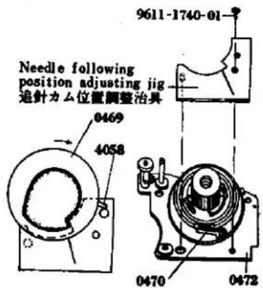
Attach the MC standard lens (F 1.4/50 mm) to the body bayonet mount and set the diaphragm ring to F 4. Then attach the special tool (031-0013-79) to the rewinding shaft. One knot portion of 4081 is to be inserted into the slot of 2010 of the shutter base plate-A, and then pull out 4081 below 2010, (See Fig. 33). Fix 2001, 2005, 0252, and 2002 to the shutter base plate-A by means of 9615-1725-04, (See Page 1). Set the speed dial to 110 sec. and ASA 50. Rotate about two and half turns 0470 of 0472 in the counter clockwise direction and attach the special tool (031-0007-79). Rotate 0469 in the clockwise direction so that 4058 attached 0469 and made of bakelite is abutted against the pin special tool, (See Fig. 34). The lengths of 4080 and 4081 are 195 mm and 237 mm respectively. When they are exchanged, the permissible dimension of the knot portion must be within the order of ± 1 mm. Otherwise, adjustment after attaching the strings can not be made. When the strings are attached, care should be taken not to overlay 4080 and 4081 on each other.
1. 追針台板取付け要領
natural_image
Pure mechanical assembly diagram without any text, numbers, or symbolsFig. 34
text_image
Needle following position adjusting jig 追針力ム位置調整治具 0469 4058 9611-1740-01 0470 04724. AV coupling string (4080)
Check if 4080 extending from the front frame is not disengaged from 1068. Engage 4080 to 4073, 4074. In this state, insert 4080 into the slot provided around 0469 of the needle following base plate in the clockwise direction. Insert 4080 into the slot portion of 0469 and then wind around the pulley of 0470 the lower side there of, Engage the knot portion with the upper slot portion from the beneath of 4068, which is then turned lightly in the clockwise direction so that 4080 may be tightened.
5. TV coupling string (4081):
First set the camera EV8, that is ASA 50, shutters speed 130 sec. and F4 and them wind about one and a half turn is the clockwise direction 2010 extending from the shutter base plate-A around 2010. Wind 4081 around 4074, two places and also around 4068 of the needle following base plate in the counter clockwise direction about one turn. The string must be passed into the inside from the notch portion of 4068 as indicated in the Fig. 36 and the knot portion must be engaged with the notch portion of 4082.
- Cam position adjustment:
Loosen two setscrews (9601-1414-02) of 4082 and rotate 4068 in the clockwise direction and 4082 in the counter clockwise direction so that the AV. and TV (4080, 4081) may be tightened. The knot portion and the portion inserted in the slot of 4080 are pasted to hold it in position. Set the camera to EV 9, that is ASA 50, shutter speed 110 sec., and F 4 and loosen two setscrews (9601-1414-02) to move 4082 for adjustment so that the straight portion of special tool (031-0007-79).
-
Insert into 4052 with its bended portion being facing upwardly, and the insert 0454. Engage 4057 with 0454 as indicated in the Fig. 38 and insert 4056. Then tighten 9451.
-
Needle following lever opening angle adjustment:
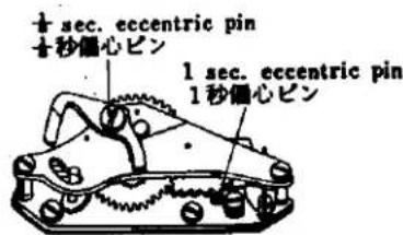
This is the adjustment for calibrating the errors and deviation of the following cam and the meter following needle. Set the camera to EV 9, that is ASA 50, shutter speed 160 sec. and F4 and then adjust by rotating the upper lever eccentric pin of 0454 so that the following needle within the meter may coincide with be checkr point in Fig. 40.
-
Take out the lens or connecting ring F4 set jig and special tool (031-0007-79).
-
Set temporarily 0451 to the needle following base plate by two setscrews (9611-1740-01, 9611-1415-02).
-
AV safety terminal adjustment:
When taking a photo and depressing the pre-view button in case of MC lens (erroneus operation), the error will be produced except the case when the diaphragm is fully opened. In order to eliminate such error, adjustment must be made so that the contact of 0451 will become "OFF" when the coupling ring of the camera body is deviated from the tully opened F1.4/50 mm lens and move 0451 forwardly and backwardly. Then secure the switch holder by means of two setscrews (9611-1740-01, 9611-1415-02) at such a position where the switch becomes "OFF" on the MC standard lens diaphragm ring out of F1.4 position. (See Fig. 39)
-
Connect to the upper terminal of 0451 the lead wire (black) extending from the beneath 0472 and to the lower terminals the lead wires (white and blue) by soldering.
-
Connect by soldering 4275 below the following needle base plate or mount the lead wires (red and black) from the front side of the camera body. Take out the speed dial and the TV pulley press nut.
-
Mount the top cover. (See Page 1)
-
追针力ム位置調整
L. Slow Governor and Shutter Base Plate-A Mounting
Check point before mounting
* Check if 2308 of the slow governor will return to its initial position when the part is displaced in the direction indicated by the arrow in the Fig. 50 to its full extent.
-
Engage two black lead wires of the body to 9111 as indicated in the Fig. 49 and withdraw the white and brown lead wires forwardly of the camera body.
-
Embed the shutter base plate-A into the camera body and hold in position by one setscrew (9612-1740-01). Place 2263 upon the base plate-A and hold them in position by one setscrew (9612-1740-01).
-
Attach 0216 by 9153, 9156 and then place 0455 over 0216, and hold them in position by two setscrews (9611-1725-01).
-
As shown in Fig. 50, move 2308 in the direction of the arrow until it stops, insert the part as it is in the body, and fasten it with the two 9611-1725-01s.
-
Mount the winding lever to the winding lever holder. Set the shutter base plate-A to bulb position and release the shutter. In this case, if the shutter curtain fails to close or run, this is because the sliding motion of 0229 and 0389 is not smooth. Adjust by bending the bended portion of 0389. Further, if the shutter axle spring is too weak, the shutter curtain fails to close or run. In this case, pull out the split washer and expand the spring.
-
When the shutter base plate-A is set the bulb position and when the shutter is released, high-speed shutter operation is made. In this case, disengage the slow governor and then charge the shutter. Then, release the shutter while checking the state of engagement of 0229 and 0298. When the engagement is not sufficient improve the engagement by bending 0229. Even if such counter-measure fails to correct the engagement, replace 0298 with new one.
-
Insert the white and brown lead wires which have been withdrawn forwardly of the camera body into 0359 and 2263.
-
Embed into the camera body 2391 in such a state where the settlement lever of 2391 is abutted against the first gear pin, and hold in position by means of two setscrews. (9611-1725-01).
-
Attach the index coupling string (5053). (See Page 7).
-
Clean the view-finder glass of 0561 and mount it by two setscrews (9158).
-
Needle following base plate then also take out 9451 and 4056. Release the engagement of 4057 with 0454 so as to pull out 0454 and take out 4057.
-
Attach TV string (4081). (See Page 23).
-
Adjust the cam position. (See Page 25).
-
Adjust the needle following lever opening angle. (See Page 25).
-
Adjust the AV safety switch contactor. (See Page 25).
-
Adjust the shutter speed. (Adjustment See Page 5).
-
Adjust the time lag. (Adjustment See Page 7).
-
Conduct current test.
-
Adjust the Intermediate terminal distance. (Adjustment See Page 7).
-
Remove the shutter dial and mount the top cover. (See Page 1).
K Shutter Base Plate-A Assembly
- Place 2017, 0213, 2016 and 2015 on 2011 in that order, and fasten them with the two 9611-1730-02s. Apply grease (006) to the circumference of 2017.
- Apply grease (006) to the speed dial shaft, insert the above assembly in the speed dial shaft, and hold it in place with 9147. Then put 2010 in the speed dial shaft from the top, place 0254 on it and tighten 9611-1725-01. Place 2007 on 0254 and fasten it with 9612-1425-02.
- Insert 2028 in the 0229 shaft, and place the latter in the shutter base plate-A, as illustrated in the diagram. Insert 2031 from the top and apply grease (006) to 0229. After placing 9792-1328-40 on the greased 0229, fasten it with 9720-0080-00. See Fig. 47 for attaching the spring.
- Insert 0226 in the hole in 0224, as shown in the Fig. 46. From the bottom, insert 9790-1322-40 or 9791-1322-40 or 9799-1322-40 in the hole and fasten with 9720-0080-00. Apply grease (012) between 0226 and the washer. Then insert 0224 in the shutter base plate-A. Insert 0221, 9793-1838-20, 2020 and 9421 from the top, as indicated in Fig. 48, with the 2020 between 2017 and 2016. Mount 2033 with the two 9611-1415-02s.
- Mount 2023 as shown in Fig. 46.
- After assembly, check that individual parts operate smoothly.
K シャッター台板A組立て要領
J. Aperture Reducing Base Plate, Resistor Base Plate and Battery Case Mounting
Check point before mounting
"Make it sure" that 2574 of the 0251 is bended as illustrated in the Fig. 43 and that the reducing rub plate (2572) must slide lightly when 2572 is rotated in the direction indicated by the arrow in the Fig. 43.
- Insert 3073 into 0357 of the bottom of the camera body. Move 2572 of 0251 to the direction indicated by the arrow in the Fig. 43, so as to abut against 9363 and in this state mount 2574 by 9611-2035-02 to the camera body so that 2574 may extend Forwardly of 0256 of the camera body. Apply lusin 3 of the 3073. (See Fig. 28)
- Set 9008 to 0251 and insert 2580 and 3065 into 9008 for engagement as indicated in the Fig. 42. Insert 2582.
- The shutter of the camera body is cocked and then adjustment must be made so when 2572 of 0251 is pushed down once the aperture setting switch becomes "OFF" and when pushed down again the switch becomes "ON" by bending 4260, 4261.
- Attach the battery case to the body with the three 9612-1750-01s.
- Place 3075 on the body and fasten 0361 with 9006 from the top. Apply oil (003) to the inside of the hole in 0361.
- Insert 1112 in the resistor base plate so that the end is under 1108, and fasten it in place with the two 9612-2045-02s.
- Mount the front base plate. (See Page 17)
- Mount the view-finder, meter block. (See Page 5)
- Check: Stroke of pre-set lever A. (See Page 43)
- Mount the top and bottom covers. (See Page 1)
M. Winding Base Plate Assembly
- Mount 3413 and 3414 on 0360 (See Fig. 54). Be sure the 0360 operates smoothly.
- Mount 3413 on 0306, insert 0306 in the position indicated in the Fig. 53, further insert 9792-2645-40 in that position, and fasten it with 9792-0190-00 (See Fig. 53).
- Apply grease (006) to the winding shaft of 0360, insert 3001 and 3078 into the winding shaft with 3077 fixed in the groove of 3001, and finally insert 3076 in the shaft. Then mount 3022 on 3017. Insert 3017 and 3022 in the winding shaft and fasten them with 3015.
- Place 3027 in the position indicated in the Fig. 53, and temporarily fasten 9602-1725-02. Mount 3027 in its groove, give a half counterclockwise turn to 3017, clamp 3017 with 3027, and fasten the latter with 9108 and 9602-1725-02.
- Insert 9792-2645-40 and 0350 in the counter dial shaft, place 3402 on them and fasten with 9110.
- Attach the spring of 0350 to the counter release lever shaft.
- After assembly, check that individual parts operate smoothly.
M. 卷上げ台板組立て要領
N. Winding Base Plate Mounting
- Open the back cover and align 0306 of the winding base platn with the projection portion of 3031 and hold it in position by two 9612-2030-01s.
- Mount 3068 by two 9612-1720-01s.
- Engage 3411 the under of the counter dial with the slot of 9270 and rotate in the counter clockwise direction the counter dial. Then close the back cover.
- Attach 9107, over which is positioned and held firmly by two 9617-1735-01s, 0359.
- When the winding lever is mounted and winding is made a few times, wind-up can not be made smoothly. In this case, iron powder or the like is dust within the idle gears, sprocket gears, etc. Therefore, clean such components so as to let them free from such foreign material.
- Adjustment of counter dial:
Open the back cover and return the counter dial to the S position. Loosen 9617-1735-01 of 0359 and with 3410 to its full extent of adjustment out wardly of camera body. Then close the back cover, 3408 is fitted in 3404 as shown in the Fig. 56. From this state, move 3410 slowly toward the inside of the camera body, them 3410 pushes 9267 so that 3404 is caused to rotate. When 3408 falls into the first tooth of 3404, tighten 9617-1735 01 of 0359. - Mount the slow governor. (See Page 31)
- Adjust the shutter speed as well as the time lag. (Adjustment See Page 5 and Page 7)
- Remove the winding lever and mount the top cover. (See Page 1)
N. 卷上げ台板取付け要領
O. Spool and Double Exposure Device Mounting
- Place 3040 and 0345 on the body in that order and attach them with the three 9611-1735-01s.
- Open the back cover, place 3039 and 3037 on the spool, and insert them in the body.
- Insert the 3031 set in the body from the bottom and fasten it with 9617-1735-01 after aligning the hole in the bottom of 3031 with the hole on the spool. Fasten 3002 to 3031 with 9617-1750-01 from the top of the body. Check that 3041 is positioned as indicated in the Fig. 58 when the projection of 3031 is crosswise. Apply grease (006) to the circumference of 3041 and the upper and lower bearings of 3031.
- Insert 0381 in the body hole from the bottom, place 0385 on 0381 and secure them with 9020.
- Place 3089 on 0381, pass 3086 through 9020 and secure them with 9020. For attaching 3086. see Fig. 59.
Caution: When mounting, be sure 3032 and 3083 operate smoothly. Give special attention to the engagement between 3032 and 3083 which should not be shallow. - Adjust the double exposure device (Adjustment See Page 9).
- Mount the winding base plate on the body (See Page 35).
- Mount the slow governor on the body (See Page 31).
- Put the top and bottom covers on the body (See Page 1).
o. スプール、多重露光装置取付け要領
P. Shutter Base Plate-B Mounting
- Insert adjustment washers in 2053 and 2054, position 2101 or 0250 as indicated in the Fig. 60 by aligning the hole of 0250 with 2053 and 2054, and fasten them with 9615-1735-02 and 9111. Place 5003 on them and fasten with 9109.
- Pass the ribbons of the second shutter curtain transvarsely of 0240 below the shutter base plate-B. (See Fig. 61)
- Hook the spring of 0247 to 9109 and mount 0247. Hold it so that it may not be taken off and the starting 2082 and 0223 in position by 9602-1430-01, 9117.
- Attach 2051 to 2060 as indicated in the Fig. 62 and tighten 9117.
- Attach 2052 to 2061 as indicated in the Fig. 62 and tighten 9117.
- Position 0240 of 0250 as shown in the Fig. 60, wind the second curtain shaft and stop 2052 with a finger by matching the end of the second curtain with the mark line on the left. Wind the first curtain shaft and press 2053 with a finger when the position about 1mm from the first curtain cope iron coincides with the mark line. Hold 2052 and 2053 with your fingers, insert 0293 in the position shown in Fig. 64. By removing the fingers, wind the first curtain shaft and stop it with the starting lever.
P. シャッター台B板取付け要領
-
Wind the second curtain shaft and stop it when the end of the second curtain coincides with the position about 1mm from the first curtain cope iron. Then insert 0298 as indicated in the diagram, place 9792-2038-40 on it and screw 9720-0120-00 into it.
-
Set the starting lever free to release the shutter, loosen 9171 of the body and set the pin of 2513 in the center of the changeover switch as shown in the diagram. Then tighten 9171.
9. Shutter Curtain Adjustment:
When you wind the shutter curtain, stop 2052 with a finger and set the starting lever free, the first curtain travels. Check which curtain, the first or second, deviates from the mark line on the body under that condition.
a. If the first curtain deviates, set the starting lever free after winding the first curtain so that only the first curtain will move. Then as certain the deviation between the right mark line and the first curtain. Insert a temporary gear between the variable gear and the first curtain screw, loosen the latter while pressing the first curtain shaft. Then turn the first curtain shaft. Then turn the first curtain shaft for length of the deviation between the first curtain and the right mark line and finally tighten the first curtain screw.
b. When the second curtain deviates, inser a temporary gear between the driving gear and the second curtain screw after winding the second curtain. Slightly loosen the second curtain screw. In the same manner as the first curtain, turn the second curtain shaft and tighten the second curtain screw at the position where the end of the second curtain coincides with the mark line.
-
Insert into the speed dial click plate 9795-3248-20 and also align and insert 2108, 2111 and 2109 into 9223. Then, fit 9223 into the hole. Align the elongated slot of the inner side 2110, with 9223 and then insert 9793-3258-20 and 2112. Next tighten 2113 until 2113 may be located in the same plane with 2107. (See Fig. 63)
-
Arrange in juxtaposition 2 lead wires of 0221 so that they may not overly on each other and in such a manner they may run along the camera body. Place a cut out portion of 0221 and 2213 by 2 pieces of 9611-1730-02. (See Fig. 63)
-
Wind up the shutter curtains and open the back cover. Then rotate the sprocket so as to position the sprocket teeth to be directed toward you, and engage 0345 into 3003. Also place the projection of 3031 in the right lateral direction. In this state, place 3004 in such a position as indicated by the figure and dress down 0393 and 3003 downwardly so that the distance between the oval hole of 3004 and 0393 may become minimum. Then, load wires foraway of the camera body and then mount the winding base plate. (See Fig. 68)
-
二幕軸を巻き上げて二幕の端を一幕の幕緑金から約1 mm 單寄りの位置に合わせて止めておき、0298を図の様に入れ9792-2038-40をおき、9720-0120-00を填める。
-
始動レバーを逃がしてシャッターを切り、ボデーの 9171 を緩め 2513 のビンを図の様に切換スイッチの中心に来る様に取付け、9171を締付ける。
9. シャッター幕調整
-
Mount the shutter base plate-A and slow governor. (See Page 31)
-
Mount the front base plate. (See Page 17)
-
Mount the finder and meter block. (See Page 5)
-
Adjust the shutter speed. (Adjustment See Page 5)
-
Adjust the time lag. (Adjustment See Page 7)
-
Check the continuity
-
Check the sync. contact and adjust the distance between the middle contactors. (Adjustment See Page 7)
-
Adjustment of the bightness:
Switch "ON" the change switch of the bottom cover and mount of the camera body. Set the ASA100 shutter speed to 1 sec. Standerd F1.4/50mm MC lens with its aperture being set to F5.6 (EV 5) then set the light luminescence box to EV 5 and look through the viewfinder to check if the meter needle comes to rest at the center of the ring of the following needle. Also set the ASA 100, shutter speed 1/500 sec., F5.6 (EV 14) then set the light luminescence box to EV 14 and check as same above mentioned.
Intermediate check points:
Check if the meter needle comes to rest within the outer periphery of the following needle (allowance in ± 0.3 EV) at the following two points
EV 8 (ASA 100, 1/8 sec., F5.6)
EV 11 (ASA 100, 1/60 sec., F5.6)
With the changeover switch of the bottom cover set to "BC", look into the finder and check with a new mercury battery (1.3V) whether the meter needle is at the check point as indicated in the diagram. When the meter needle deviates from the check point, adjust it by turning the semi-fixing resistor for the checker located at the bottom of the body.
- Checking the stroke of the preset lever A.
The specification for the position of the preset lever A is between 5.7mm and 7.7mm from the body center when the lever is reset. When reducing the aperture, the preset lever A must be away from the body center and its stroke must be less than 0.5mm. Put the preset stroke gauge (031-0004-79) on the body and set the shutter speed of the body to "B" (bulb). Be sure the gauge's lever is above the 6.7mm line in the diagram when winding the body. Then release the shutter and with the shutter release button held down, the gauge's lever must be below the 0.5mm line. Release the shutter and check if the gauge's lever is within the 6.7mm and 7.7mm lines.
- Mount the top and bottom covers on the body. (See Page 1)
Q. Sprocket Mounting
-
Fasten the two 9123s to 3049 and attach it to 0348. Insert 3046 in the body as illustrated in the diagram, put 3049 and 0348 into the hole of 3046 from the top of the body, and fasten 0348 with the two 9615-1425-02s. Apply grease (006) to the interior of 3046 and the sliding surface of 3048.
-
Set 3050 with the three 9615-1425-02s from the bottom of the body, insert 3051 in 3049 and 3054 in 3053, and fasten 3053 (reverse screw). Apply grease (006) to 3051.
-
Adjusting the Position of 3054
The 3053 must be reset when the shutter release stop lever comes off the release shaft after pressing the 3053 and operating the winding lever or until the winding lever comes in contact with the stopper. The 3032 should not be turned during the operation of the winding lever.
Adjustment:
* When the 3053 comes off earlier than the shutter release stop lever, stop the 3053 before the winding is completed and move 3054 counterclockwise to delay the resetting of 3053.
* When the 3053 comes off later than the shutter release stop lever, move 3054 clockwise to quicken the resetting of 3053.
-
Secure 3066 to the bottom of the camera body by 9004. Hook 3067 as illostrated in the Fig. 71 and attach 3075, 0361 by means of 9006.
-
Insert 0389 from the upper side of the camera body, and then insert into 0389, 3043 from the front side of the camera body, push down 3043 and fit 9720-0150-00 into 0389. Apply grease (No. 006) to 3043.
-
Mount 9127, 3003 by means of 9128. Apply greas (030) to 3026, and 3003 into 3026.
-
Affix 0235 with 2 pieces of 9103.
-
Insert 0393 to 0389 groove position from upper side of body them put, on 3004, following the shutter button operation lever-B connecting inside to 0389 groove of down side body. Apply grease (006, 012) to inside part of 0393, 3004.
-
Mount the Shutter base plate-B. (See Page 39)
Q. スプロケット取付け要領
R. Shutter Curtains Mounting
Check points before mounting :
* In order to check if the shutter curtains are installed in parallel, rotate 2053 in the clockwise direction as indicated in the Fig. 72 so as to wind up the first shutter curtain and also check and make it sure that there is no relative inclination between the end of the first shutter curtain and 2053. In the similar manner, rotate 2063 in the clockwise direction to wind up the second shutter curtain and check and make it sure that there is no relative inclination between 2053 and the second shutter curtain.
- Lay the body no its end, insert the second curtain in the hole at the front of the body, and keep the ribbon slightly slack. (See Fig. 73)
- By setting 2060 of the first curtain on the ribbon of the second curtain, insert the 2060 into the inner hole of the body. Thread the first set through the ribbons of the second curtains indicated in the diagram. (See Fig. 73)
- Insert 9405 in 2061 of the second curtain, and 9404 in 2060 of the first curtain respectively, further insert the 2060 and 2061 in the hole in 0297, and fasten them with 2 pieces of 9612-1725-02. (See Fig. 73)
- Mount 2073 (reverse screw) on 2060 and 2061, and hook 2074 and 2075 on them. Then turn the 2060 and 2061 two or three times to take up the curtains. (See Fig. 73)
- Set 0459 with 2 pieces of 9163, solder the wire (yellow) of 0459 as shown in the diagram and insert the body's wires (yellow, red, green and blue) in the hole of the body. Then solder them as indicated in the diagram. Also, solder the resistor as shown in the diagram. (See Fig. 74)
- Engage the reverton lever spring with the preset lever stopper. Insert 2054 into the opening at the lower side of the camera body as indicated in the Fig. 74. Engage the ribbons of the first shutter curtain with the first curtain roller-A and B of the second shutter curtain and then insert 2053 into the hole on your side.
- Stand uprightly the camera body and mount 0191 by means 2 pieces of 9611-1720-02.
- Mount the shutter base plate-B. (See Page 39)
R. シャッター幕取付け要領
取付け前の点検
- Insert 9403 in 2513 and fasten it with 9171. Apply grease (012) to the sliding surface between 2513 and 9403.
- Place 0256 on the body, further attach 2511 and 0259 to it, and fasten them with 9104. Apply oil (003) to the sliding surface of 2511.
- Place 2524, 9406 and 2508 on the body in that order and fasten them. Attach 2524 and 2522 as shown in Fig. 77. Apply grease (006) to the inside of 2508.
- Place 1013 and 2569 on the body and fasten them with 9613-2350-01. Place 4256 on 1013 and fasten it with 9053.
- Place 3055 on the body and fasten it with 9004. Attach 3056 as indicated in Fig. 78.
- Place 3058, 9793-2250-20, 0395, 3071 or 3072 and 3069 on the body in that order, and fasten them with 9121. Insert 3070 in 9121 and attach 3058 and 3070 as shown in Fig. 79.
- Place 0398 and 9791-3142-40 and 3059 in that order, pass 9408 through them and fasten them with 9439.
- Tighten 9005 and attach 2521 as illustrated in Fig. 80.
5. その他組立て要領
A. Finder-Back Adjustment .... 1
B. In-Finder Adjustment 3
C. Body-Back Adjustment 5
D.Shutter Speed Adjustment 5
E. Time Lag Adjustment 7
F. Intermediate Terminal Distance Adjustment 7
G. Double Exposure Device Adjustment 9
調 整 編
A. Finder-Back Adjustment
Loosen three setscrews(9132) for the prism holder and raise or lower three adjustment screws (9101) for adjusting focus. (See Fig. 1)
When the adjustment is to be made from the beginning turn the adjustment screws about three turns to raise them from their initial positions where the adjustment screws have been screwed first. Then, start adjustment from such raised positions. When adjustment is made, care should be taken not to disconnect the lead wires or give damage to the meter since the yare located adjacent the adjustment screws. When the following adjustment from a to d is made and when you look the image, care must be taken to lightly press or hold the pinchers portion. Then, tighten three setscrews(9132) and check again if the image is in focus at such tightened position.
a. When the left portion is of a wave from as illustrated in the Fig. 2 the left insufficient so that the focus adjusting screw on the left must be lowered for adjustment.
b. When the left portion is of crossing waves from, the left side is over or in excess so that the left side focus adjusting screw must be raised for adjustment. Conversely when the right side is of a wave form or crossing waves from, the right side is insufficient or excess respectively, so that the right side focus screw must be adjusted accordingly. (See Fig. 2)
c. When the lower portion is of a wave form as shown in the Fig. 2 the lower side is insufficient so that the lower focus adjusting screw must be lowered for adjustment.
d. When the lower portion is of crossing waves form, the lower side portion is in excess so that the lower side focus adjusting screw must be raised for adjustment. Conversely when the upper portion is of a wave form or crossing waves form, the upper side is insufficient or in excess respectively so that the right and left side focus adjusting screws must be adjusted.
A. ファインダーバック調整要領
text_image
Left side insufficiency 左不足 Left side over 左行き過ぎ Lower side insufficiency 下不足 Lower side over 下行き過ぎB. In-Finder Adjustment
Diaphragm In-Finder Lens Holder
When the diaphragm in-finder lens holder is incorrectly positioned, loosen the two set screws located on 0535 and adjust the holder by moving it vertically, horizontally or diagonally. After adjusting, tighten the set screws. (See Fig. 3)
Diaphragm In-Finder Mirror Holder
When the diaphragm in-finder mirror holder is deviated vertically, move 0538 (diaphragm in-finder mirror holder) up or down using a pair of pliers and adjust it by bending. (See Fig. 4) When the diaphragm in-finder mirror holder is deviated horizontally, turn 0538 right or left using a pair of pliers and adjust it by bending. (See Fig. 4)
B. インファインダー調整
絞りインファインダーレンズホルダー
D. Shutter Speed Adjustment
Make it sure that the slow governor is not engaged when the shutter is released at such high speed from 1/1000 to 1/60. If the slow governor is engaged, adjust by rotating the eccentric pin of the slow adjustment lever (1/8 adjustment) so that the slow gear may not engage. The shutter curtain speed variation must be in the order of 30%.
a. Measure the shutter velocity at 1/60 sec. Adjust by means of the second shutter curtain spring so as to obtain the curtain time from 13.5 to 14 ms.
b. Adjust the forward and backward openings by the first shutter curtain.
c. Measure the shutter speed at 1/500 sec. Adjust the shutter speed by means of the eccentric pin.
d. Measure the shutter speed at 1/1000 sec. Adjust the shutter speed through the hole of the shutter dial and also confirm the shutter curtain velocity variation.
e. Also check the shutter speed at 1/250 sec., 1/125 sec. and 1/60 sec.
f. Measure the shutter speed at 1/8 sec. Adjust the slow adjustment eccentric pin of the slow governor.
g. Also check the shutter speed at 1 sec., 1/2 sec., 1/4 sec. and 1/15 sec.
h. Measure the shutter speed at 1/30 sec. Adjust the split pin of the slow speed cam (2015).
i. Check and adjust bulb, time and shutter curtains bound.
D. シャッタースピード調整
C. Body-Back Adjustment
Set the shutter speed dial to B than stay open the shutter curtain, next open the back cover and place the mask cover scale anvil with its projection portion being positioned at the right. Fit the body over the projected portion of the mask cover scale anvil and place the dial guage upon the washer place. Then, slide the dial guage up and down, to the right and left and further along the diagonal lines and measure the dimensions of the four corners. Loosen four setscrews (9616-1733-02), and rotate four body back adjustment screws (9616-1733-02) which can be seen from the opening of the front frame so that the body back may be positioned in the order of 43.7_-0^+0.03mm and the parallelism in the order of 0.02mm .
The body back adjustment screw may be raised or lowered by 0.35mm upon one rotation of the screw. When the screw is rotated angularly about 10 digrees of angle, the screw can be raised or lowered by 0.01mm. After adjustment, tighten one setscrew (9615-2040-02) and also tighten four setscrews (9616-1733-02).
c. ボデーバック調整
text_image
1/2 sec. adjusting hole 1/2秒調整穴 1/2 sec. adjusting groove 1/2秒調整 1/2 sec. adjusting pin 1/2秒調整ピンFig. 8
text_image
± sec. eccentric pin ±秒信心ピン 1 sec. eccentric pin 1秒信心ピンE. Time lag Adjustment
When FP time lag is too short, loosen the setscrew (9602-1430-01) of the FP earth contactor (0223) attached to the underside of the shutter base plate-A and push the earth contactor (0223) in the direction opposite to the terminal side cf the FP contactor (2220) so that the terminal distance between the earth contactor (0223) and the FP contactor (2220) may be shortened.
When FP time lag is too long, widen the terminal distance between the earth contactor (0223) and the FP contactor (2220). When the contact efficiency is too low bend the waist portion of the FP contactor (2220) so as to increase the contact pressure.
When switching-in of X time lag is too soon, adjust the contactor distance as is the case of FP adjustment. Remove the front base frame and widen the distance between the X-contactor-B (2217) of the X-contactor holder (0211) and the X-contactor-A (2215).
- When the contact efficiency of X-contactor is low bend the waist portion of the X-contactor-B (2217) so as to increase the contact pressure.
F. Intermediate terminal distance adjustment
When the shutter is charged, it happens sometimes that the FP contactor (2220) of the FP terminal comes to contact with the FP earth contactor (0223), resulting in short-circuiting. Therefore, the distance between the earth contactor (0223) from the front side of the camera body must be so adjusted to be in the order of 1 to 1.2 mm as illustrated in the Fig. 13.
E. タイムラグ調整
G. Double Exposure Device Adjustment
System operation and Adjustment
Winding the Film: When turning the spool counterclockwise, be sure there is an opening (0.3mm in the diagram) between 3085 and 3084 and also an opening (0.5mm in the diagram) between 9365 and 3089.
Adjustment: When there is no opening between 3084 and 3085, loosen the two set screws in 9020, move 3081 toward the back cover and tighten the 9020 set screws. When there is no opening between 3089 and 3085, bend 3089 (part A in the diagram) inward (in the direction of the arrow) after determining that 3089 (part A in the diagram) inward (in the direction of the arrow) after determining that 3089 operates properly. (See Fig. 14)
Rewinging the Film
- On depressing 3053, an opening (0.3mm in the diagram) between 3066 and 9365 must occur and the claw of 3085 engages with 3084.
Adjustment: When an opening does not occur between 3066 and 9365, loosen the set screws in 9020, move 3081 toward the lens and fasten 9020. Attention must be given to the setting of the spool base plate system. If the claw of 3085 does not engage with 3084, be sure to check whether 3085 is operating correctly. (See Fig. 15)
- When turning the spool clockwise, 3089 pushes 9365 to remove the claw of 3085 from 3084, causing an opening (0.3mm in the diagram) between 3084 and 3085.
Adjustment: If no opening occurs between 3085 and 3084 when turning the spool clockwise, bend 3089 (part A in the diagram) outward (in the direction of the arrow) after checking that 3089 and 3085 operate correctly. (See Fig. 16) Be sure, however, that when turning the spool counterclockwise, the claw of 3085 engages with 3089, causing an opening between 3085 and 3084. (See Fig. 17)