Maxxum 400Si - Camera KONICA MINOLTA - Free user manual and instructions
Find the device manual for free Maxxum 400Si KONICA MINOLTA in PDF.

User questions about Maxxum 400Si KONICA MINOLTA
0 question about this device. Answer the ones you know or ask your own.
Ask a new question about this device
Download the instructions for your Camera in PDF format for free! Find your manual Maxxum 400Si - KONICA MINOLTA and take your electronic device back in hand. On this page are published all the documents necessary for the use of your device. Maxxum 400Si by KONICA MINOLTA.
USER MANUAL Maxxum 400Si KONICA MINOLTA
| MINOLTA DYNAX 500si | (2092–100) |
| MINOLTA DYNAX 500si DATE | (2092–200) |
| MINOLTA MAXXUM 400si | (2092–300) |
| MINOLTA MAXXUM 400si DATE | (2092–400) |
| MINOLTA α 303si | (2092–600) |
natural_image
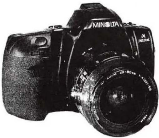
Black-and-white photo of a MINI SLA DSLR camera with visible lens and aperture (no text or symbols on body)CAMERA
Type
: 35mm SLR with built-in flash and control of autofocus (AF) and autoexposure (AE)
LENS MOUNT
: Minolta A type bayonet mount
SHUTTER
Type
: Electronically controlled, vertical traverse, focal plane type
Range
: 1/2000 to 30 sec., bulb
X-sync.speed
: 1/90 sec. or slower
Self-timer
: Electronic with 10 sec. delay; cancelable (indicated by LED lamp)
FLASH(Built-in flash)
Guide number
: Raised and lowered manually
coverage
: 12
Recycling time
: to 28mm focal length lens
P mode flash
: Approx. 2 sec. (Based on Minolta's standard test method)
A, S, M mode flash
: When built-in flash is up, fires automatically when needed, manual fill-flash or flash cancel selectable
Other features
: When built-in flash is up, flash always fires
: Control of Pre-flash for red-eye reduction, and wireless-flash available
FILM TRANSPORT
Threading
: Auto-threading; auto-advance to first frame
Film advance
: Single-frame advance or continuous advance by 1 frame per second
Film rewind
: Automatic rewind or manual start of rewind
Rewind time
: Approx. 16 sec. (using 24-exposure film)
Battery performance (Based on Minolta's standard test method)
: Approx. 50 rolls using 24-exposure film
Approx. 20 rolls using 24-exposure film with flash ON 50% of exposure Approx. 13 rolls using 24-exposure film with flash ON 100% of exposure
VIEWFINDER
Type : Eye-level fixed roof mirror
Focusing screen : Acute matte screen
Field of view : 90%
Magnification : 0.75 (with 50mm lens at infinity)
Diopter : -1 diopter (adjustment available using eyepiece corrector)
Eyepiece cup : Soft type
Indication for panorama (-600 only)
: Light-shielding panorama frame
DISPLAYS
Body data panel

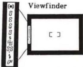
text_image
(●) 6 6 8 s 4 88 # P1 Viewfinder [ ]EXPOSURE CONTROL SYSTEM
Metering : TTL type 8-zone honeycomb pattern metering (adjustment available for panorama format); SPC1 for ambient light, SPC2 for TTL flash metering Metering range : EV1 to 20 (with ISO 100, F1.4 lens)
Exposure mode selection : P, A, S, M
Subject program selection
: Portrait, Landscape, Close-Up, Sports Action, Night-Portrait
Manual SS & aperture settings
: Shutter speed: 1.0-stop increments, Aperture: 1/2-stop increments
Film-speed setting : Automatic setting for DX-coded films ISO25 to 5000 (1/3-stop increments)
Recommended range with flash: ISO25 to 1000
ISO 100 set for non DX-coded film
Exposure compensation : ±3EV (1/2-stop increments)
AE lock : AE locks when focus is locked
AF system
Type : Minolta's TTL phase-detection type
AF sensor : One CCD sensor
AF sensitivity range : EV -1 to 18 (with ISO 100 in ambient light)
Focus mode : Autofocus or manual focus switchable
Built-in AF illuminator : Built-in flash fires automatically when raised in low-light/low-contrast to aid focusing; cancelable
Focus control : Predictive focus control for moving subjects Automatic AF mode changeover between continuous and one-shot
OTHERS
Panorama(-600 only) : Selected by Panorama Switch with panorama frame in viewfinder to shield light; data imprinting position changes for panorama format with Panorama DATE model
Autozoom (with xi-series lens) : Auto-compact
Power
Battery : One 6V 2CR5 lithium battery
Battery for DATE : One CR2025 lithium battery
Dimensions
-100,-300 :147.5(W)×92.5(H)×66.5(D)mm
-200,-400 :147.5(W)×92.5(H)×67.5(D)mm
-600 : 148.5(W)×92.5(H)×67.5(D)mm
Weight
-100, -300 : 380g (without battery) -200, -400 : 385g (without 2CR5, including CR2025) -600 : 395g (without 2CR5, including CR2025)
Mechanism Description
Mechanism and electric circuit of 2092 are almost the same as those of 2085. Refer to 2085 Mechanism Description for details.
CONTENTS
1. Mechanical block description
(1)Block diagram P. 2
(2)Function of each block P. 3
2. Body control circuit
(1)Switch P. 4
(2)Timing chart P.5
(3) Input/output of motor control signal P. 5
(4) Circuit diagram
①DC/DC converter circuit P. 6
②Overall circuit P. 7


1. Mechanical block description
(1) Block diagram
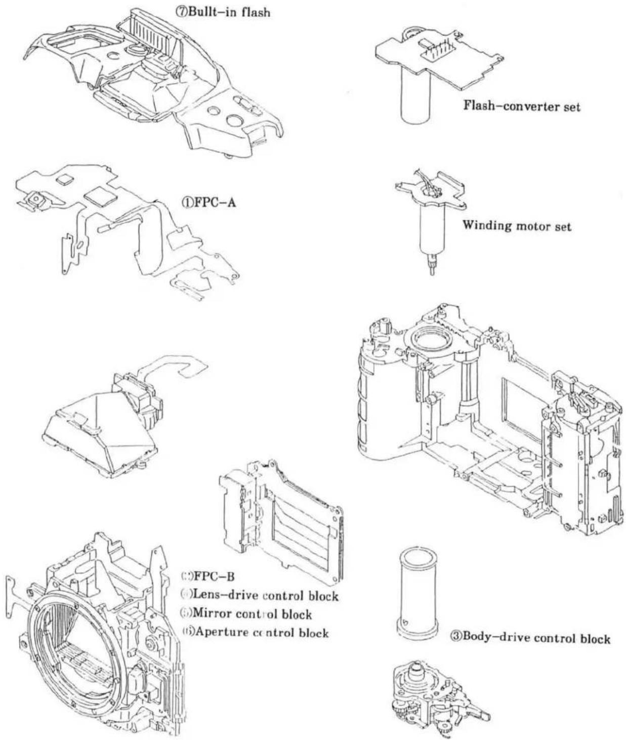
(∵)FPC-B
(4) Lens-drive control block
①Mirror control block
(6)Aperture control block
③Body-drive control block
(2) Function of each block
① FPC-A (IC1, 4, 5, 6)
- Controls the whole sequence and calculates each set of data.
·Supplies power to M1 (Body-drive motor), M2 (AF-motor).
- Controls each set of serial data (lens, flash, data back).
② FPC-B [1C3]
- Detects focus point necessary for AF operation.
③ Body-drive control block
- Consists of one-rotation cam block interlocked with MI rotation, advance and rewind-gears, transmitting gears, and mirror-charge-lever.
- Controls mechanical shutter-release, stopping down the lens, mirror and shutter charge, film advance/rewind.
④ Lens-drive control block
- Consists of M2, AF coupler, AF encoder, and AF drive gears.
- Drives lenses through AF coupler monitoring M2 rotation with AF encoder.
⑤ Mirror control block
- Consists of mirror-charge-lever, link-lever, etc.
- Drives up and down the mirror.
- Charges shutter with shutter-charge-lever interlocked with charge-lever.
⑥ Aperture-control block
Consists of SL2, aperture-encoder PCB, aperture-ring interlock gears, shutter-charge block, and mirror-charge block.
Monitors moving-amount of aperture-ring on aperture-encoder PCB at stop-down operation, and determines aperture by separating SL2.
⑦ Built-in flash
- In P mode, and if built-in flash is raised, it fires automatically when necessary.
· In S, A, M mode, and if built-in flash is raised, it always fires.
4 (2092)
2. Body control circuit
(1) Switch
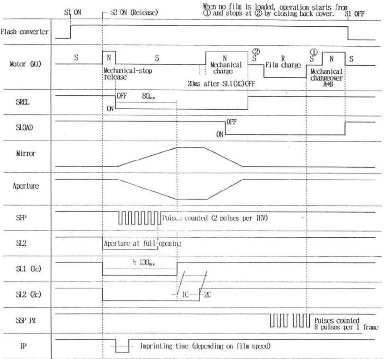
(2) Timing chart
[ Sutter release & film advance ]
other
| Signal | Phase Description | |--------|--------------------------------------| | S1 | ON | | S2 | ON (Release) | | S3 | When no film is loaded, operation starts from ① and stops at ② by closing back cover. | | S4 | S1 OFF | | S5 | Off (80ms) | | S6 | Mechanical-stop release | | S7 | Mechanical charge | | S8 | Film charge | | S9 | Mechanical changeover A+B | | S10 | OFF (80ms) | | S11 | OFF (80ms) | | S12 | On (80ms) | | S13 | Off (80ms) | | S14 | Off (80ms) | | S15 | Off (80ms) | | S16 | Off (80ms) | | S17 | Off (80ms) | | S18 | Off (80ms) | | S19 | Off (80ms) | | S20 | Off (80ms) | | S21 | Off (80ms) | | S22 | Off (80ms) | | S23 | Off (80ms) | | S24 | Off (80ms) | | S25 | Off (80ms) | | S26 | Off (80ms) | | S27 | Off (80ms) | | S28 | Off (80ms) | | S29 | Off (80ms) | | S30 | Off (80ms) | | S31 | Off (80ms) | | S32 | Off (80ms) | | S33 | Off (80ms) | | S34 | Off (80ms) | | S35 | Off (80ms) | | S36 | Off (80ms) | | S37 | Off (80ms) | | S38 | Off (80ms) | | S39 | Off (80ms) | | S40 | Off (80ms) | | S41 | Off (80ms) | | S42 | Off (80ms) | | S43 | Off (80ms) | | S44 | Off (80ms) | | S45 | Off (80ms) | | S46 | Off (80ms) | | S47 | Off (80ms) | | S48 | Off (80ms) | | S49 | Off (80ms) | | S50 | Off (80ms) | | S51 | Off (80ms) | | S52 | Off (80ms) | | S53 | Off (80ms) | | S54 | Off (80ms) | | S55 | Off (80ms) | | S56 | Off (80ms) | | S57 | Off (80ms) | | S58 | Off (80ms) | | S59 | Off (80ms) | | S60 | Off (80ms) | | S61 | Off (80ms) | | S62 | Off (80ms) | | S63 | Off (80ms) | | S64 | Off (80ms) | | S65 | Off (80ms) | | S66 | Off (80ms) | | S67 | Off (80ms) | | S68 | Off (80ms) | | S69 | Off (80ms) | | S70 | Off (80ms) | | S71 | Off (80ms) | | S72 | Off (80ms) | | S73 | Off (80ms) | | S74 | Off (80ms) | | S75 | Off (80ms) | | S76 | Off (80ms) | | S77 | Off (80ms) | | S78 | Off (80ms) | | S79 | Off (80ms) | | S80 | Off (80ms) | | S81 | Off (80ms) | | S82 | Off (80ms) | | S83 | Off (80ms) | | S84 | Off (80ms) | | S85 | Off (80ms) | | S86 | Off (80ms) | | S87 | Off (80ms) | | S88 | Off (80ms) | | S89 | Off (80ms) | | S90 | Off (80ms) | | S91 | Off (80ms) | | S92 | Off (80ms) | | S93 | Off (80ms) | | S94 | Off (80ms) | | S95 | Off (80ms) | | S96 | Off (80ms) | | S97 | Off (80ms) | | S98 | Off (80ms) | | S99 | Off (80ms) | | IIP | Imprinting time (depending on film speed)※ N : Normal drive R : Reverse drive S : Drive stop
(3) Input/output of motor control signal (1C-4)
| Motor Operation | Input | Output | ||||||||
| 22 | 21 | 24 | 23 | 48 | 47 | 61 | 60 | 46 | 57 | |
| M 1, M 2 OFF | H | H | H | H | H | H | L | L | H | L |
| M 1 Normal drive | L | H | H | H | L | H | L | H | H | L |
| M 1 Reverse drive | H | L | H | H | H | L | H | L | H | L |
| M 2 Normal drive | L | H | H | L | H | H | L | H | L | L |
| M 2 Reverse drive | H | L | H | L | H | L | L | L | H | H |
| M 1, M 2 Brake | L | L | L | L | H | H | H | H | H | H |
(4) 回路図 / Circuit diagram
■ Accompanied with the pattern modification of F1C-D (2092-4004), treatment of Back-Cover Release Unit (2089-0121) is changed. Follow the instruction below for repair.
When replacing FPC-D with replacement part, replace Back-Cover Release Unit as a set. Cutting a pattern of Back-Cover Release Unit is not necessary for this replacement FPC-D. (Refer to page 14 of Repair Guide.)
■Replace FPC-D and Back Cover Release Unit as a set.
| FPC-D (2092-4004) | Back Cover Release Unit (2089-0121) |
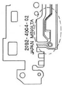 Previous※Not available as replacement part Previous※Not available as replacement part |  |
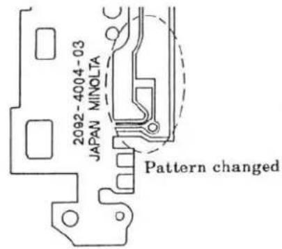 New※Available as replacement part New※Available as replacement part | Do not cut the pattern. |
1 (2092)
text_image
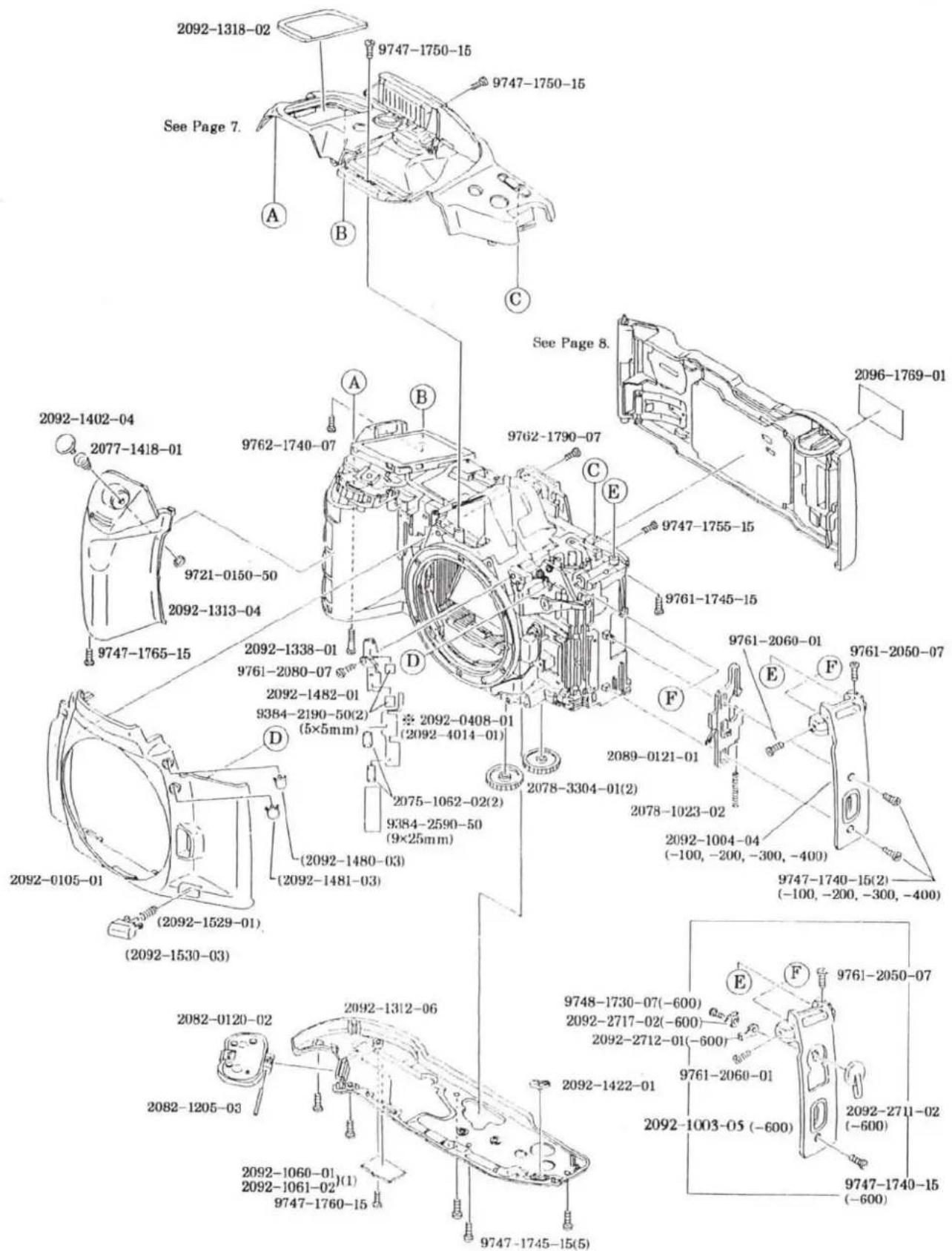
2092-1318-02 9747-1750-15 9747-1750-15 See Page 7. A B C See Page 8. 2096-1769-01 2092-1402-04 2077-1418-01 9762-1740-07 9762-1790-07 9747-1755-15 2092-1313-04 9747-1765-15 2092-1338-01 9761-2080-07 2092-1482-01 9384-2190-50(2) (5×5mm) 2092-0408-01 (2092-4014-01) D 2078-3304-01(2) 2089-0121-01 2078-1023-02 2092-1004-04 (-100, -200, -300, -400) 9747-1740-15(2) (-100, -200, -300, -400) 2092-0105-01 (2092-1529-01) (2092-1480-03) (2092-1481-03) (2092-1482-01) (5×5mm) 2075-1062-02(2) 9384-2590-50 (9×25mm) 2089-0121-01 E F 9761-2050-07 9761-2060-01 9761-2717-02(-600) 2092-2717-02(-600) 2092-2712-01(-600) 9761-2060-01 2092-1422-01 9748-1730-07(-600) 2092-1442-01 9747-1745-15(5) 9747-1760-15 9747-1765-15 2092-1312-06 2082-0120-02 2082-1205-03 2092-1060-01 (1) 2092-1061-02 (9×5mm) 9747-1765-15


MINOLTA MAXXUM 400SI
| PART NUMBER | DESCRIPTION | QTY |
| 2092-0105-01 | FRONT COVER UNIT | 1 |
| 2092-1480-03 | FLASH-CONTROL BUTTON | 1 |
| 2092-1481-03 | EXPOSURE-COMPENSATION BUTTON | 1 |
| 2092-1529-01 | FOCUS-MODE BUTTON SP | 1 |
| 2092-1530-03 | FOCUS-MODE BUTTON | 1 |
| 2082-0120-02 | BATTERY COVER SET | 1 |
| 2089-0121-01 | BACK-COVER RELEASE UNIT | 1 |
| 2092-1003-05 | BACK-COVER RELEASE COVER (-600) | 1 |
| 2092-1004-04 | BACK-COVER RELEASE COVER (-100, -200, -300, -400) | 1 |
| 2078-1023-02 | LOCK SP | 1 |
| 2092-1060-01 | SERIAL NUMBER PLATE | 1 |
| 2092-1061-02 | SERIAL NUMBER PLATE (MALAYSIA) | 1 |
| 2075-1062-02 | OVER RIDE CONTACT | 2 |
| 2082-1205-03 | BATTERY COVER HINGE AXIS | 1 |
| 2092-1312-06 | BOTTOM COVER | 1 |
| 2092-1313-04 | GRIP COVER | 1 |
| 2092-1318-02 | LCD WINDOW | 1 |
| 2092-1338-01 | SCREW | 1 |
| 2092-1402-04 | SHUTTER-RELEASE BUTTON | 1 |
| 2077-1418-01 | RELEASE BUTTON SPRING | 1 |
| 2092-1422-01 | REWIND BUTTON | 1 |
| 2092-1482-01 | EXPOSURE-COMPENSATION BUTTON BASE | 1 |
| 2096-1769-01 | PANORAMA STICKER (-600) | 1 |
| 2092-2711-02 | PANORAMA SWITCH (-600) | 1 |
| 2092-2712-01 | PANORAMA OPERATION LEVER-A (-600) | 1 |
| 2092-2717-02 | SPANO. CONTACT (-600) | 1 |
| 2078-3304-01 | REWIND GEAR-B | 2 |
| 9384-2190-50 | DOUBLE-FACED TAPE (PER ROLL) | 2 |
| 9384-2590-50 | MENDING TAPE (1R/50M) | 1 |
| 9721-0150-50 | E-RING | 1 |
| 9747-1740-15 | SCREW (-100, -200, -300, -400) | 2 |
| 9747-1740-15 | SCREW (-600) | 2 |
| 9747-1745-15 | SCREW | 5 |
| 9747-1750-15 | SCREW | 2 |
| 9747-1755-15 | SCREW | 1 |
| 9747-1760-15 | SCREW | 1 |
| 9747-1765-15 | SCREW | 1 |
| 9748-1730-07 | SCREW | 1 |
| 9761-1745-15 | SCREW | 1 |
| 9761-2050-07 | SCREW | 1 |
| 9761-2060-01 | SCREW | 1 |
| 9761-2080-07 | SCREW | 1 |
| 9762-1740-07 | SCREW | 1 |
| 9762-1790-07 | SCREW | 1 |
| 2092-0408-01 | SEE PAGE 4 | |
| 2092-4014-01 | FPC-N | 1 |
text_image
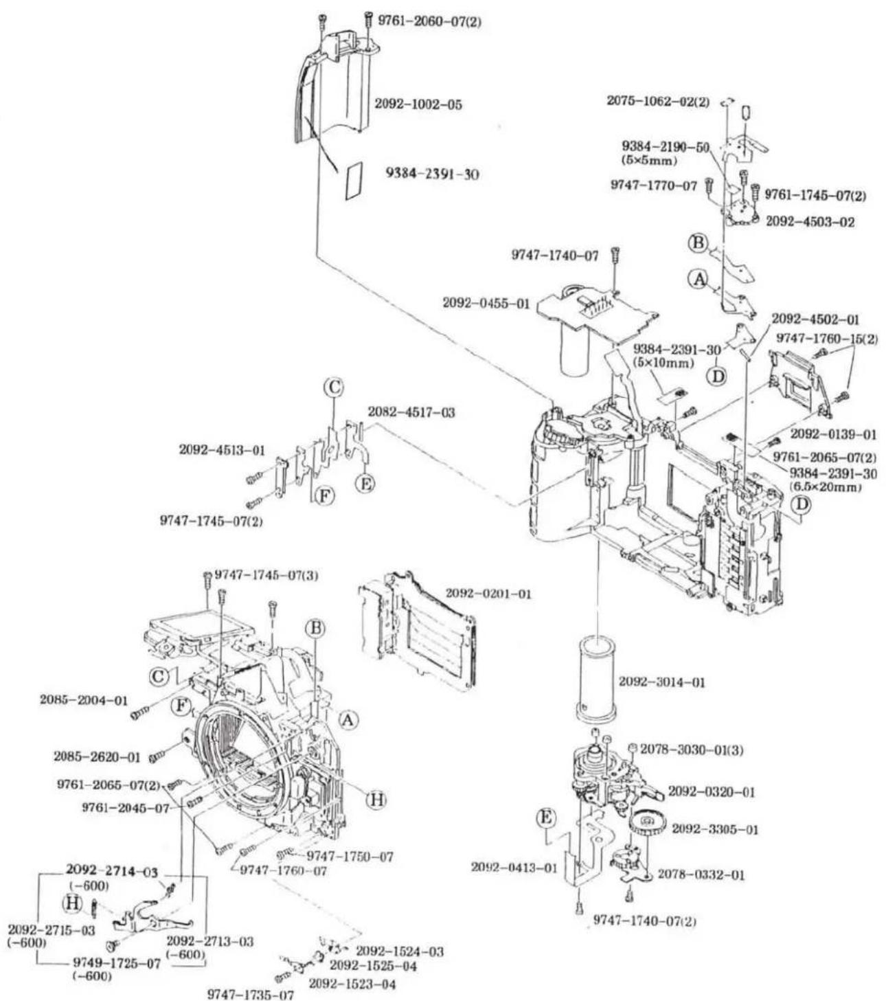
9761-2060-07(2) 2092-1002-05 9384-2391-30 2092-0455-01 2092-4513-01 2082-4517-03 9747-1745-07(2) 2092-0201-01 9747-1745-07(3) 2085-2004-01 2085-2620-01 9761-2065-07(2) 9761-2045-07 2092-2714-03 (-600) 2092-2715-03 (-600) 9749-1725-07 (-600) 2092-2713-03 (-600) 9747-1735-07 2092-1524-03 2092-1525-04 2092-1523-04 9747-1740-07 9384-2391-30 (5×10mm) 9384-2190-50 (5×5mm) 9747-1770-07 9761-1745-07(2) 2092-4503-02 B A D C E F G H I J K L M N O P Q R S T U V W X Y Z

MINOLTA MAXXUM 400SI
| PART NUMBER | DESCRIPTION | QTY |
| 2092-0139-01 | EYEPIECE FRAME UNIT | 1 |
| 2092-0201-01 | SHUTTER UNIT | 1 |
| 2092-0320-01 | WINDING BASE PLATE UNIT | 1 |
| 2078-0332-01 | REWIND BASE PLATE SET | 1 |
| 2092-0413-01 | FPC-M SET | 1 |
| 2092-0455-01 | FLASH CONVERTER PCB SET | 1 |
| 2092-1002-05 | STRAP EYELET (R) | 1 |
| 2075-1062-02 | OVER RIDE CONTACT | 2 |
| 2092-1523-04 | SRAF. CONTACT-A | 1 |
| 2092-1524-03 | SRAF. CONTACT-B | 1 |
| 2092-1525-04 | SRAF. CONTACT SPACER | 1 |
| 2085-2004-01 | SCREW | 1 |
| 2085-2620-01 | SCREW | 1 |
| 2092-2713-03 | PANORAMA COUPLING LEVER-A (-600) | 1 |
| 2092-2714-02 | PANORAMA OPERATION SP-A (-600) | 1 |
| 2092-2715-03 | PANORAMA COUPLING SP (-600) | 1 |
| 2092-3014-01 | SPOOL | 1 |
| 2078-3030-01 | SILENT COLLAR | 3 |
| 2092-3305-01 | REWIND GEAR-C | 1 |
| 2092-4502-01 | RUBBER CONNECTOR | 1 |
| 2092-4503-02 | CONNECTOR BASE PLATE | 1 |
| 2092-4513-01 | CONNECTOR PRESSURE | 1 |
| 2082-4517-03 | A-F-M RUBBER CONNECTOR | 1 |
| 9384-2190-50 | DOUBLE-FACED TAPE (PER ROLL) | 1 |
| 9384-2391-30 | ACETATE TAPE (PER ROLL) | 2 |
| 9747-1735-07 | SCREW | 1 |
| 9747-1740-07 | SCREW | 3 |
| 9747-1745-07 | SCREW | 5 |
| 9747-1750-07 | SCREW | 1 |
| 9747-1760-07 | SCREW | 1 |
| 9747-1760-15 | SCREW | 2 |
| 9747-1770-07 | SCREW | 1 |
| 9749-1725-07 | SCREW | 1 |
| 9761-1745-07 | SCREW | 2 |
| 9761-2045-07 | SCREW | 1 |
| 9761-2060-07 | SCREW | 2 |
| 9761-2065-07 | SCREW | 4 |
| 9790-4165-40 | WASHER (DISCONTINUED) | 1 |
| 9384-2391-30 | ACETATE TAPE (PER ROLL) | 1 |
text_image
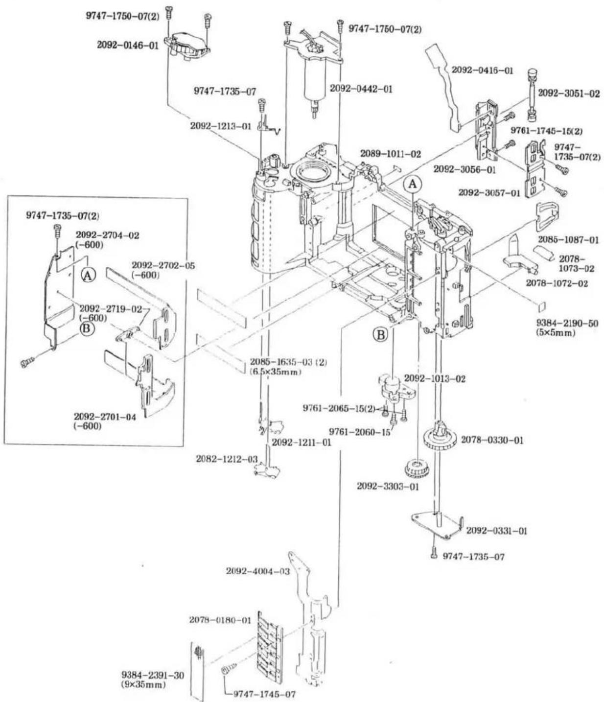
9747-1750-07(2) 2092-0146-01 9747-1735-07 2092-1213-01 9747-1750-07(2) 2092-0442-01 2092-0416-01 2092-3051-02 9761-1745-15(2) 9747- 1735-07(2) 2089-1011-02 2092-3056-01 2092-3057-01 2085-1087-01 2078- 1073-02 2078-1072-02 9384-2190-50 (5×5mm) A B 9747-1735-07(2) 2092-2704-02 (-600) A 2092-2702-05 (-600) 2092-2719-02 (-600) B 2092-2701-04 (-600) 2085-1635-03 (2) (6.5×35mm) 2082-1212-03 2092-1013-02 9761-2065-15(2) 9761-2060-15 2092-1211-01 2092-3303-01 2092-4004-03 2078-0180-01 9747-1735-07 2092-331-01 9747-1745-07 9384-2391-30 (9×35mm)

MINOLTA MAXXUM 400SI

| PART NUMBER | DESCRIPTION | QTY |
| 2092-0146-01 | DIAL UNIT | 1 |
| 2078-0180-01 | DX CONTACTS SET | 1 |
| 2078-0330-01 | REWIND FORK SET | 1 |
| 2092-0331-01 | REWIND FORK BASE PLATE UNIT | 1 |
| 2092-0416-01 | FPC-P SET | 1 |
| 2092-0442-01 | WINDING MOTOR UNIT | 1 |
| 2089-1011-02 | LOADING INDEX | 1 |
| 2092-1013-02 | TRIPOD BASE PLATE | 1 |
| 2078-1072-02 | FILM CARTRIDGE RECEIVER | 1 |
| 2078-1073-02 | CARTRIDGE RECEIVER SP | 1 |
| 2085-1087-01 | SIDE SP | 1 |
| 2092-1211-01 | BATTERY CONTACT-A (-) | 1 |
| 2082-1212-03 | BATTERY CONTACT-B (+) | 1 |
| 2092-1213-01 | BATTERY DETECT SW | 1 |
| 2085-1635-03 | TAPE (PER ROLL) (-600) | 2 |
| 2092-2701-04 | PANORAMA FRAME PLATE-A (-600) | 1 |
| 2092-2702-05 | PANORAMA FRAME PLATE-B (-600) | 1 |
| 2092-2704-02 | PANORAMA FRAME HOLDER-A (-600) | 1 |
| 2092-2719-02 | PANORAMA COUPLING LEVER-B (-600) | 1 |
| 2092-3051-02 | FILM ROLLER | 1 |
| 2092-3056-01 | FILM GUIDE | 1 |
| 2092-3057-01 | FPC-P HOLDER | 1 |
| 2092-3303-01 | REWIND GEAR-A | 1 |
| 2092-4004-03 | FPC-D | 1 |
| 9384-2190-50 | DOUBLE-FACED TAPE (PER ROLL) | 1 |
| 9384-2391-30 | ACETATE TAPE (PER ROLL) | 1 |
| 9747-1735-07 | SCREW | 6 |
| 9747-1745-07 | SCREW | 1 |
| 9747-1750-07 | SCREW | 4 |
| 9761-1745-15 | SCREW | 2 |
| 9761-2060-15 | SCREW | 1 |
| 9761-2065-15 | SCREW | 2 |
4 (2092)

text_image
2092-1316-03 2092-4201-02 2092-4202-01 (2) 9384-2190-50 (2) (5×5mm) 2092-1411-02 (2092-4011-01) A 2092-0408-01 (2092-5817-01) (9747-1735-07) (2) (2092-5815-03) (2092-0426-01) (2092-4206-01) (2092-5816-01) (9384-2391-30) (19×20mm) (2078-5145-01) (2) (2092-5019-01) (2092-5805-01) (2092-5025-03) (2092-5026-04) Some (2092-5027-04) 2092-1438-01 (2) 2092-4012-01 9384-2590-50 (9×15mm) 2092-1438-01 2092-4010-01 A 2092-5011-02 9747-1750-07 (3) 2092-5013-03 2092-0580-01 (9384-2391-30) (2) (10×15mm) (2085-5012-02) 2092-5035-01 (2092-5036-01) Some (2092-5037-01)MINOLTA MAXXUM 400SI
| PART NUMBER | DESCRIPTION | QTY |
| 2092-0408-01 | FPC-A SET | 1 |
| 2092-0580-01 | PENTA-PRISM UNIT | 1 |
| 2092-0426-01 | BACK LIGHT UNIT | 1 |
| 2092-4011-01 | FPC-K | 1 |
| 2092-4206-01 | LCD 2 | 1 |
| 2092-4207-01 | LCD 2 CONNECTOR | 1 |
| 2085-5012-02 | FRESNEL LENS SP | 1 |
| 2092-5019-01 | PENTA-PRISM LIGHT SHIELD SHEET | 1 |
| 2078-5145-01 | MIRROR CUSHION | 2 |
| 2092-5805-01 | FOCUSING SCREEN | 1 |
| 2092-5815-03 | VIEWFINDER LCD HOLDER | 1 |
| 2092-5816-01 | LCD 2 PRESSURE | 1 |
| 2092-5817-01 | SCREW | 2 |
| 9747-1735-07 | SCREW | 2 |
| 9384-2391-30 | ACETATE TAPE (PER ROLL) | 3 |
| 2092-1316-03 | LCD 1 PRESSURE | 1 |
| 2092-1411-02 | SHUTTER-RELEASE BASE | 1 |
| 2092-1438-01 | CLICK CONTACT | 3 |
| 2092-4010-01 | FPC-J | 1 |
| 2092-4012-01 | FPC-L | 1 |
| 2092-4201-02 | LCD 1 | 1 |
| 2092-4202-01 | LCD 1 CONNECTOR | 2 |
| 2092-5011-02 | PENTA INSULATION SHEET | 1 |
| 2092-5013-03 | PENTA PRESSURE | 1 |
| 2092-5025-03 | VB ADJUSTMENT PLATE-A (T=0.2) | SOME |
| 2092-5026-04 | VB ADJUSTMENT PLATE-B (T=0.15) | SOME |
| 2092-5027-04 | VB ADJUSTMENT PLATE-C (T=0.1) | SOME |
| 2092-5035-01 | VB ADJUSTMENT PLATE-D (T=0.2) | SOME |
| 2092-5036-01 | VB ADJUSTMENT PLATE-E (T=0.15) | SOME |
| 2092-5037-01 | VB ADJUSTMENT PLATE-F (T=0.1) | SOME |
| 2092-5156-01 | MIRROR CUSHION-A (DISCONTINUED) | 2 |
| 9384-2190-50 | DOUBLE-FACED TAPE (PER ROLL) | 2 |
| 9384-2590-50 | MENDING TAPE (1R/50M) | 1 |
| 9747-1750-07 | SCREW | 3 |
5 (2092)
2092-0499-01
text_image
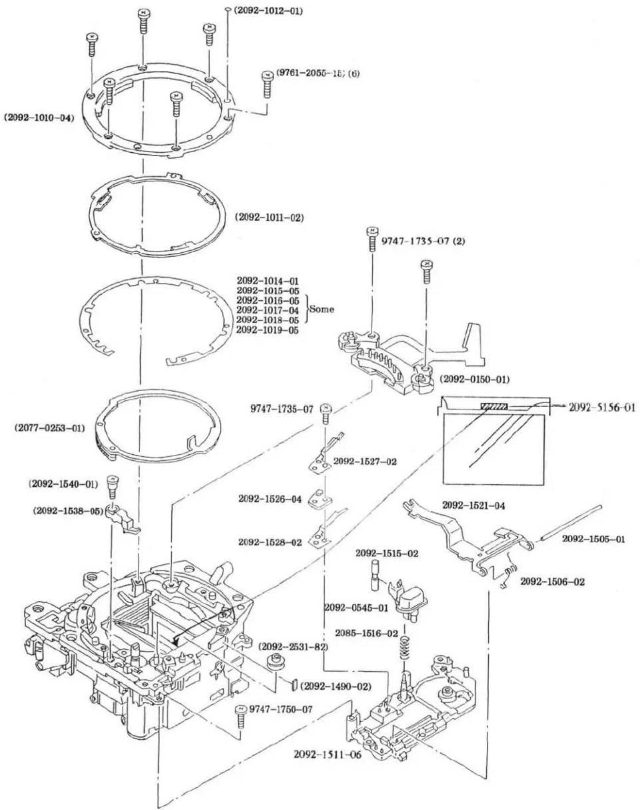
(2092-1010-04) (2092-1012-01) (9761-2055-157 (6)) (2092-1011-02) 2092-1014-01 2092-1015-05 2092-1016-05 2092-1017-04 2092-1018-05 Some 2092-1019-05 2092-10150-01 (2092-0150-01) (2077-0253-01) (2092-1540-01) (2092-1538-05) 9747-1735-07 9747-1735-07 2092-1527-02 2092-1526-04 2092-1528-02 2092-1515-02 2092-0545-01 2085-1516-02 (2092-2531-82) (2092-1490-02) 9747-1750-07 2092-1511-06 2092-1505-01 2092-1506-02

MINOLTA MAXXUM 400SI
| PART NUMBER | DESCRIPTION | QTY |
| 2092-0499-01 | MIRROR BOX UNIT | 1 |
| 2092-0150-01 | BL CONTACT HOLDER SET | 1 |
| 2077-0253-01 | APERTURE RING SET | 1 |
| 2092-1010-04 | BAYONET LENS MOUNT | 1 |
| 2092-1011-02 | BAYONET SP | 1 |
| 2092-1012-01 | MOUNTING INDEX | 1 |
| 2092-1490-02 | SPACER | 1 |
| 2092-1538-05 | COUPLER STOP LEVER | 1 |
| 2092-1540-01 | SCREW | 1 |
| 2092-2531-82 | RING ROLLER | 1 |
| 9747-1735-07 | SCREW | 2 |
| 9761-2055-15 | SCREW | 6 |
| 2092-0545-01 | LENS-RELEASE UNIT | 1 |
| 2092-1014-01 | BB ADJUSTMENT WASHER-A (T=0.05) | SOME |
| 2092-1015-05 | BB ADJUSTMENT WASHER-B (T=0.08) | SOME |
| 2092-1016-05 | BB ADJUSTMENT WASHER-C (T=0.1) | SOME |
| 2092-1017-04 | BB ADJUSTMENT WASHER-D (T=0.12) | SOME |
| 2092-1018-05 | BB ADJUSTMENT WASHER-E (T=0.15) | SOME |
| 2092-1019-05 | BB ADJUSTMENT WASHER-F (T=0.2) | SOME |
| 2092-1505-01 | COUPLER LEVER AXIS | 1 |
| 2092-1506-02 | COUPLER LEVER SP | 1 |
| 2092-1511-05 | AF/M CONTACT BASE PLATE | 1 |
| 2092-1515-02 | LENS-RELEASE | 1 |
| 2085-1516-02 | LOCK SET SP | 1 |
| 2092-1521-04 | COUPLER LEVER | 1 |
| 2092-1526-04 | SLLK. CONTACT SPACER | 1 |
| 2092-1527-02 | SLLK. CONTACT-A | 1 |
| 2092-1528-02 | SLLK. CONTACT-B | 1 |
| 9747-1735-07 | SCREW | 1 |
| 9747-1750-07 | SCREW | 1 |
| 2092-5156-01 | MIRROR CUSHION-A | 1 |
6 (2092)
2092-0499-01
text_image
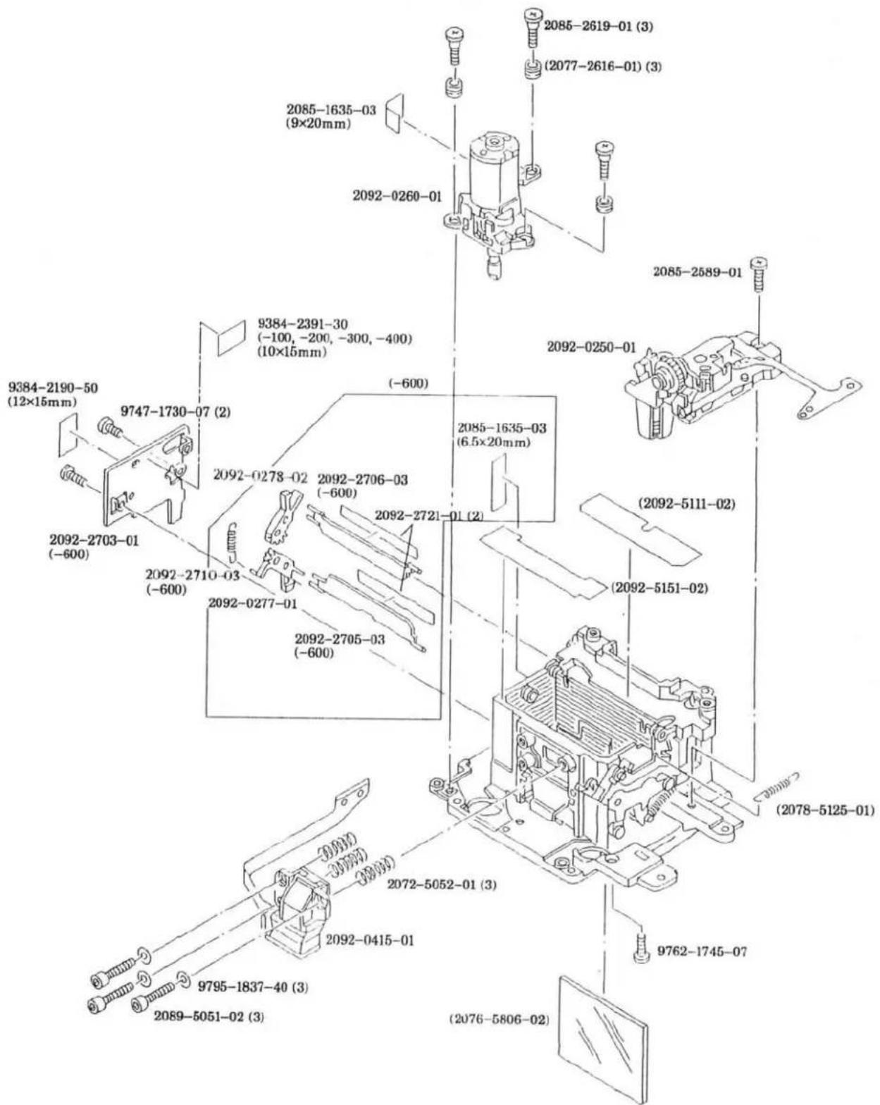
2085-1635-03 (9×20mm) 2092-0260-01 2085-2619-01 (3) (2077-2616-01) (3) 2085-2589-01 9384-2391-30 (-100, -200, -300, -400) (10×15mm) 2092-0250-01 (2092-2190-50 (12×15mm) 9747-1730-07 (2) 2092-0278-02 2092-2706-03 (-600) 2085-1635-03 (6.5×20mm) 2092-2703-01 (-600) 2092-2710-03 (-600) 2092-2721-01 (2) 2092-2705-03 (-600) (2092-5111-02) (2092-5151-02) (2078-5125-01) 2072-5052-01 (3) 2092-0415-01 9762-1745-07 9795-1837-40 (3) 2089-5051-02 (3) (2076-5806-02)MINOLTA MAXXUM 400SI
| PART NUMBER | DESCRIPTION | QTY |
| 2092-0250-01 | APERTURE PLATE UNIT | 1 |
| 2092-0260-01 | AF MOTOR BASE UNIT | 1 |
| 2077-2616-01 | COLLAR | 3 |
| 2092-0277-01 | PANORAMA OPERATION LEVER UNIT-C (-600) | 1 |
| 2092-0278-02 | PANORAMA OPERATION LEVER UNIT-B (-600) | 1 |
| 2092-0415-01 | FPC-B SET | 1 |
| 2092-0499-01 | MIRROR BOX UNIT | 1 |
| 2092-5111-02 | LIGHT SHIELD SHEET-A | 1 |
| 2078-5125-01 | MIRROR DOWN SP | 1 |
| 2092-5151-02 | LIGHT SHIELD SHEET-B | 1 |
| 2076-5806-02 | MAIN MIRROR | 1 |
| 2085-1635-03 | TAPE (PER ROLL) (-600) | 2 |
| 2085-2589-01 | SCREW | 1 |
| 2085-2619-01 | SCREW | 3 |
| 2092-2703-01 | PANORAMA FRAME HOLDER-B (-600) | 1 |
| 2092-2705-03 | PANORAMA FRAME PLATE-C (-600) | 1 |
| 2092-2706-03 | PANORAMA FRAME PLATE-D (-600) | 1 |
| 2092-2710-03 | PANORAMA OPERATION SP-B (-600) | 1 |
| 2092-2721-01 | PROTECTION SHEET | 2 |
| 2089-5051-02 | SCREW | 3 |
| 2072-5052-01 | AF ADJUSTMENT SP | 3 |
| 9384-2190-50 | DOUBLE-FACED TAPE (PER ROLL) | 1 |
| 9384-2391-30 | ACETATE TAPE (PER ROLL) (-100, -200, -300, -400) | 1 |
| 9747-1730-07 | SCREW | 2 |
| 9762-1745-07 | SCREW | 1 |
| 9795-1837-40 | WASHER | 3 |
7 (2092)
2092-0131-01
2092-0133-01
2092-0135-01
2092-0133-01
2092-0135-01
2092-0133-01
2092-0135-01
2092-0135-01
2092-0133-01
2092-0135-01
2092-0133-01
2092-0135-01
2092-0133-01
2092-0133-01
2092-0135-01
2092-0133-01
2092-0133-01
2092-0135-01
2092-0133-01
2092-0133-01
2092-0135-01
2092-0133-01
2092-0133-01
2092-0135-01
2092-0133-01
text_image
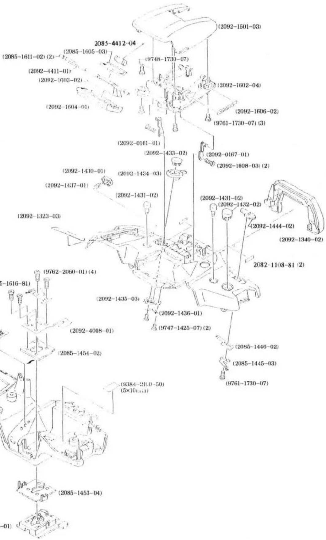
(2092-1601-03) (2085-4412-04) (2085-1605-03) (2092-4411-01) (2092-1603-02) (2092-1604-01) (9748-1730-07) (2092-1602-04) (2092-1606-02) (9761-1730-07) (3) (2092-0161-01) (2092-1433-02) (2092-0167-01) (2092-1608-03) (2) (2092-1430-01) (2092-1434-03) (2092-1431-02) (2092-1431-02) (2092-1432-02) (2092-1444-02) (2092-1340-02) (2082-1108-81) (2) (9762-2060-01) (4) (9761-1616-81) (2092-1435-03) (2092-4008-01) (2085-1454-02) (9384-219.0-50) (5×10^1.65) (9747-1425-07) (2) (2085-1446-02) (2085-1445-03) (9761-1730-07) (2085-1453-04) (-01)


MINOLTA MAXXUM 400SI
| PART NUMBER | DESCRIPTION | QTY |
| 2092-0131-01 | TOP COVER UNIT (-100, -200) | 1 |
| 2092-0133-01 | TOP COVER UNIT (-300, -400) | 1 |
| 2092-0135-01 | TOP COVER UNIT (-600) | 1 |
| 2085-0145-01 | ACC. SHOE SET | 1 |
| 2092-0161-01 | FLASH HOLDER UNIT-B | 1 |
| 2092-0167-01 | FLASH HOLDER UNIT-A | 1 |
| 2092-1323-03 | DOUBLE-FACED TAPE-A | 1 |
| 2092-1324-02 | DOUBLE FACED TAPE-B (DISCONTINUED) | 1 |
| 2092-1340-02 | EYEPIECE CUP | 1 |
| 2092-1430-01 | APERTURE BUTTON | 1 |
| 2092-1431-02 | DRIVE/SELF BUTTON | 2 |
| 2092-1432-02 | EXPOSURE-MODE BUTTON | 1 |
| 2092-1433-02 | PROGRAM-RESET BUTTON | 1 |
| 2092-1434-03 | S/C SELECTOR | 1 |
| 2092-1435-03 | S/C CLICK PLATE | 1 |
| 2092-1436-01 | S/C CONTACT | 1 |
| 2092-1437-01 | APERTURE BUTTON SP | 1 |
| 2092-1444-02 | MAIN SWITCH | 1 |
| 2085-1445-03 | MAIN SWITCH CONTACT | 1 |
| 2085-1446-02 | MAIN SWITCH CLICK PLATE | 1 |
| 2085-1453-04 | SHOE BASE | 1 |
| 2085-1454-02 | SHOE SETTING PLATE | 1 |
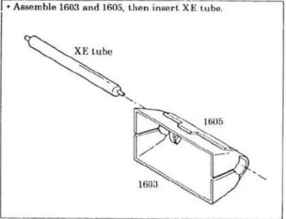
| 2092-1601-03 | FLASH COVER | 1 |
| 2092-1602-04 | FLASH BASE PLATE | 1 |
| 2092-1603-02 | XE HOLDER-A | 1 |
| 2092-1604-01 | FLASH PANEL | 1 |
| 2085-1605-03 | XE HOLDER-B | 1 |
| 2092-1606-02 | UP/DOWN SP | 1 |
| 2092-1608-03 | SCREW | 2 |
| 2085-1611-02 | RUBBER TUBE | 2 |
| 2085-1616-81 | POP-UP DETECT CONTACT | 1 |
| 2082-1108-81 | SPACER | 2 |
| 2085-1635-03 | TAPE (PER ROLL) | 1 |
| 2092-4008-01 | FPC-H | 1 |
| 2092-4411-01 | XE TUBE | 1 |
| 2085-4412-04 | TRIGGER COIL | 1 |
| 9384-2190-50 | DOUBLE-FACED TAPE (PER ROLL) | 1 |
| 9747-1425-07 | SCREW | 2 |
| 9748-1730-07 | SCREW | 1 |
| 9761-1730-07 | SCREW | 4 |
| 9762-2060-01 | SCREW | 4 |
8 (2092)
NON DATE MODEL (-100, -300)

text_image
9749-1730-07 (2) (2078-5145-01) (2092-1106-01) (2092-1111-02) 2078-0114-01 (2076-1112-02) 2092-0117-01DATE MODEL (-200, -400, -600)
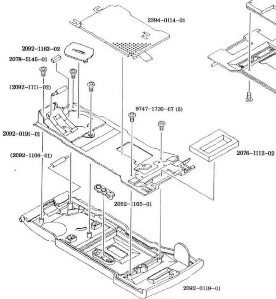
text_image
2094-0114-01 2092-1163-02 2078-5145-01 (2092-1111-02) 2092-0191-01 (2092-1106-01) 9747-1730-07 (5) 2076-1112-02 2092-1165-01 2092-0119-01
text_image
2419-1292-01 (-200, -400) 2094-4261-01 (-600) 9747-1730-07 (2)MINOLTA MAXXUM 400SI
| PART NUMBER | DESCRIPTION | QTY |
| 2078-0114-01 | PRESSURE PLATE SET | 1 |
| 2092-0117-01 | BACK COVER UNIT (-100, -300) | 1 |
| 2092-1106-01 | BACK COVER HINGE AXIS | 1 |
| 2092-1111-02 | BACK COVER ROLLER | 1 |
| 2076-1112-02 | LIGHT SHIELD SPONGE | 1 |
| 2078-5145-01 | MIRROR CUSHION | 1 |
| 9749-1730-07 | SCREW | 2 |
| 2094-0114-01 | PRESSURE PLATE SET | 1 |
| 2092-0119-01 | BACK COVER UNIT (-200, -400, -600) | 1 |
| 2092-1106-01 | BACK COVER HINGE AXIS | 1 |
| 2092-0191-01 | DATE MODULE BASE PLATE UNIT (-200, -400, -600) | 1 |
| 2092-1111-02 | BACK COVER ROLLER | 1 |
| 2076-1112-02 | LIGHT SHIELD SPONGE | 1 |
| 2092-1163-02 | BATTERY COVER (-200, -400, -600) | 1 |
| 2092-1165-01 | KEY | 1 |
| 2419-1292-01 | DATE MODULE (-200, -400) | 1 |
| 2094-4261-01 | DATE MODULE (-600) | 1 |
| 2078-5145-01 | MIRROR CUSHION | 1 |
| 9747-1730-07 | SCREW | 7 |
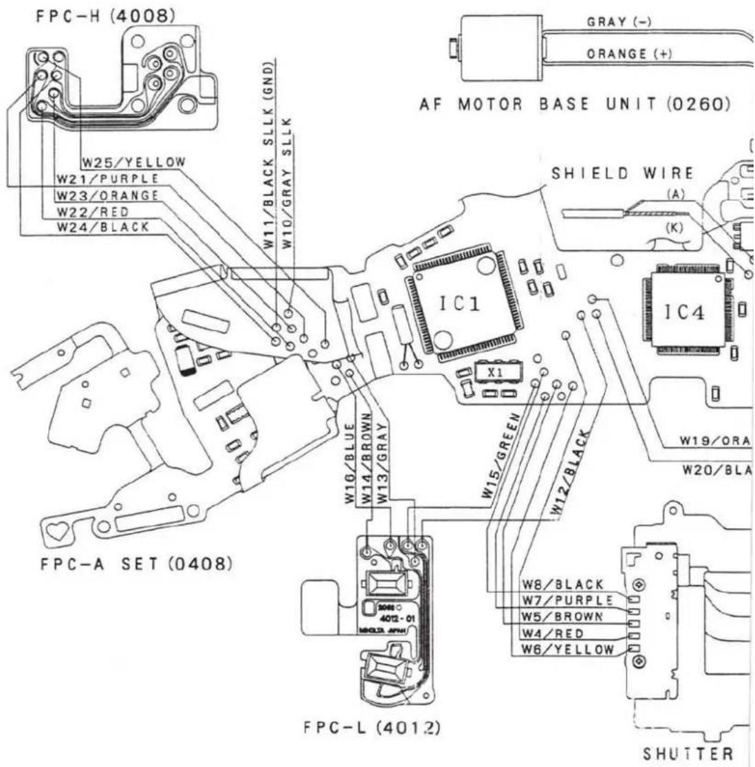
■ Wiring Diagram 1 (2092)

text_image
2 0 7 6 - 4 4 0 1 - 0 1 (S H I E L D) 2085-4402-03 (W 4 1) 2 0 9 2 - 4 4 0 3 - 0 1 (W 4 2) 9 3 9 1 - 1 2 0 7 - □□ (W 2 8, W 2 9) 9 3 9 1 - 0 8 0 7 - □□ (O T H E R)
text_image
W32/BLACK LCD1 PRESSURE (1316) BATTERY CONTACT-A (-) (2082-1211)
text_image
XE TUBE TRIGGER COIL W42 W41 RED LINEBLACK LII
text_image
FPC-H (4008) W25/YELLOW W21/PURPLE W23/ORANGE W22/RED W24/BLACK W11/BLACK SLLK (GND) W10/GRAY SLLK AF MOTOR BASE UNIT (0260) SHIELD WIRE (A) (K) IC1 X1 W16/BLUE W14/BROWN W13/GRAY W15/GREEN W12/BLACK W8/BLACK W7/PURPLE W5/BROWN W4/RED W6/YELLOW W19/ORA W20/BLA FPC-A SET (0408) FPC-L (4012) SHUTTER■Contents of this manual are in accordance with the assembly procedure.
Therefore, follow the reverse procedure when disassembling.
■Refer to Wiring diagram on Parts List, page 9 for wiring.
Symbols
■ : Cautions and keypoints
G : Grease
B: Adhesive
T : Tool
CONTENTS
Procedure ■ Description of procedure
Precautions 2-3
Body Assembly 4-5
②Winding Base Plate Unit, Winding Motor Unit Installation 6
③Mirror Box Assembly- I
④Mirror Box Assembly- II 8-9
■Sw. REL timing adjustment 9
5Penta Prism Unit, FPC-A Set Installation 10-11
⑥Mirror Box Unit Installation 12-13
■Mechanical operation Check....13
7 External parts Installation 14
■Back Cover Unit Installation 15
■Top Cover Unit Assembly 16-17
■ Adjustment/check required after repair 18
■Preparation Before Adjustment-1 19
■Body Back Adjustment- I 20
■Body Back Adjustment- II 21
■Viewfinder Back Adjustment 22
■Manual SS & X-Sync. Time-Lag Check 23
AE Level Check 24
■Aperture Control Check....24
Flash Level Check (Using strobe tester
■Manual set SS Adjustment 26
■Aperture preset Adjustment 27
■AE Adjustment....28
■Flash Level Adjustment....29
■Pre-Flash Level Adjustment 30
■Wireless Flash Level Adjustment 31
B.C. Lock Voltage Adjustment 32
All LCD Displays On Check 33
■Preparation Before Adjustment-2 (AF adjustment) 34
①AF Area Adjustment 35
②Pitch, Yaw Adjustment 36
③EZ Adjustment 37
Error code on HIT Controller 38
Tools & Instruments 39
■Subsidiary materials 39


Precautions
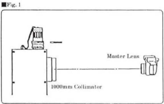
■To discharge
- Before disassembly, be sure to discharge main condenser as in Fig. 1.

text_image
Fig. 1 ■ Use discharger or resistance (200-300Ω/3W). Check the voltage after discharged, completely discharged. W28/ORANGE W31/GRAY■To activate without Top Cover (Fig. 2)
- Solder indicated part-a on FPC-A Set to short-circuit.
- Replacement FPC-A Set is initially short circuitted at the part-b. So when using the replacement FPC-A Set, you don't need to short circuit the part-a.
※Be sure to unsolder the part-a, or to cut the part-b before installing Top Cover.
Fig. 2

text_image
part-b part-aPrecautions
Chemicals
Handle chemicals of high volatility with care, use of which will affect to your health and the environment.
- Store them sealed in a specific place to prevent from exposure to a high temperature or direct sunlight.
- Avoid dividing them into small containers and prevent from vaporization.
- Keep containers sealed when not in use.
- Avoid using them as much as possible. When required, remove only required amount from the container to make full use.
Plastic parts
- When cleaning the plastic parts, use cleaning paper or cloth. Never use thinner, ketone, ether.
- When installing the plastic parts, insert the specific screws vertically to the parts. (Be careful not to tighten too much.)
PCBs
Since PCBs use MOS IC, you must reduce a static electricity. When repairing a PCB itself, or when wiring, please perform your work as illustrated above.
When grounding is impossible, connect the cable to a steel desk or shelf.
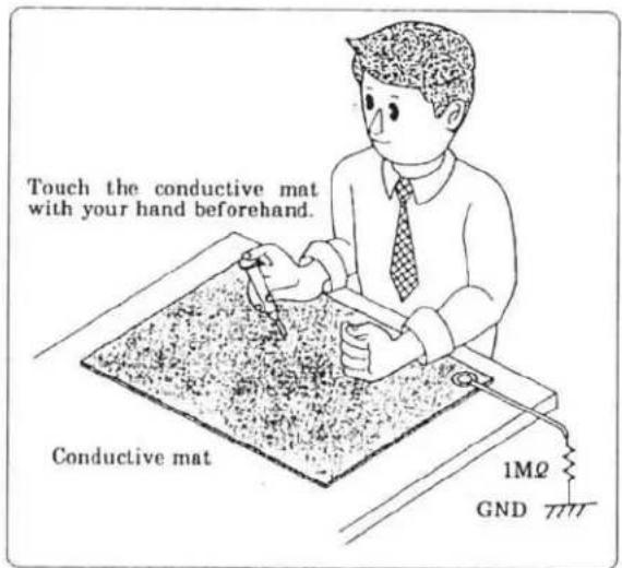
text_image
Touch the conductive mat with your hand beforehand. Conductive mat 1MΩ GND①Body Assembly

text_image
9747-1750-07 (2) 0146 9747-1735-07 1213 FPC-P Set ■Fig. 2 3051 ■Press fit. 9761-1745-15(2) 9747- 1735-07 (2) 3056 3057 2089-1011 2085-1087 ■Press fit. 2078-1073 2078-1072 9384-2190-50 (5×5mm) ■Fig. 1 (For -600 only) 9747-1735-07 (2) A 2702 2704 2719 B 2701 2082-1211 ■Press fit. 2082-1212 ■Press fit. 1013 9761-2060-15 (3) 3303 0331 FPC-D ■Fig. 3 2078-0180 9384-2391-30 (10×35mm) ■Fig. 4Fig. 1 (For -600 only)
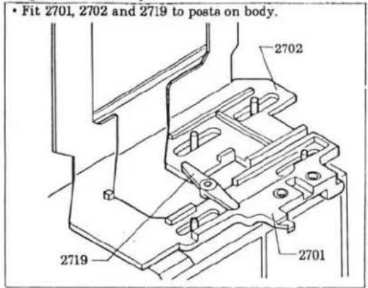
text_image
• Fit 2701, 2702 and 2719 to posts on body. 2702 2719 2701Fig. 2
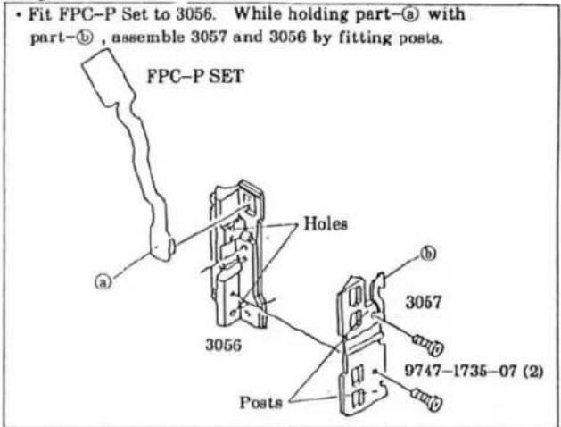
text_image
• Fit FPC-P Set to 3056. While holding part-③ with part-①, assemble 3057 and 3056 by fitting posts. FPC-P SET Holes 3056 Posts 3057 9747-1735-07 (2)Fig. 3
- Fit holes of FPC-D to posts on body to install.

text_image
Body 9384-2190-50 (5×5mm) FPC-D Holes Posts ■ Solder to short-circuit. (For -100,-200,-300,-400) Open circuit (For -600)Fig. 4
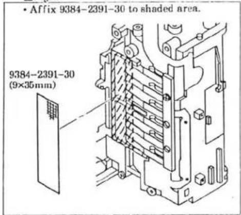
text_image
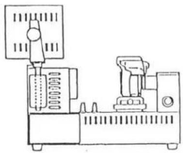
• Affix 9384-2391-30 to shaded area. 9384-2391-30 (9×35mm)② Winding Base Plate Unit, Winding Motor Unit Installation
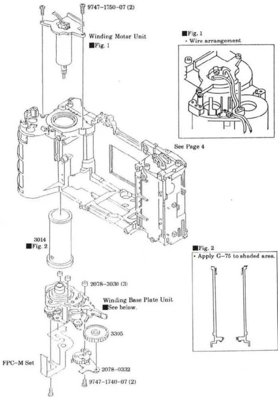
text_image
9747-1750-07 (2) Winding Motor Unit Fig. 1 ■Fig. 1 • Wire arrangement See Page 4 3014 ■Fig. 2 2078-3030 (3) Winding Base Plate Unit ■See below. 3305 FPC-M Set 2078-0332 9747-1740-07 (2) ■Fig. 2 • Apply G-75 to shaded area.■Installing Winding Base Plate Unit
- Set Cam gear to the indicated position so that Mirror Charge Lever is set to the position of arrow. (Charge completed.)
- Install Winding Base Plate Unit to the body.

text_image
Mirror Charge Lever Cam Gear③Mirror Box Assembly- I
■Install in the order of ① to ④.
Fig. 4
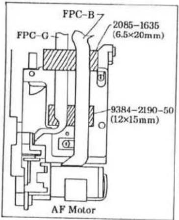
text_image
FPC-B 2085-1635 (6.5×20mm) FPC-G 9384-2190-50 (12×15mm) AF MotorFig. 2

text_image
2705 2706
text_image
2705 2706 0277 0278 2710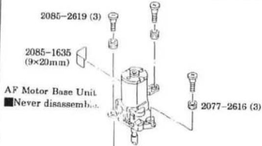
text_image
2085-2619 (3) 2085-1635 (9×20mm) AF Motor Base Unit ■ Never disassemibn 2077-2616 (3)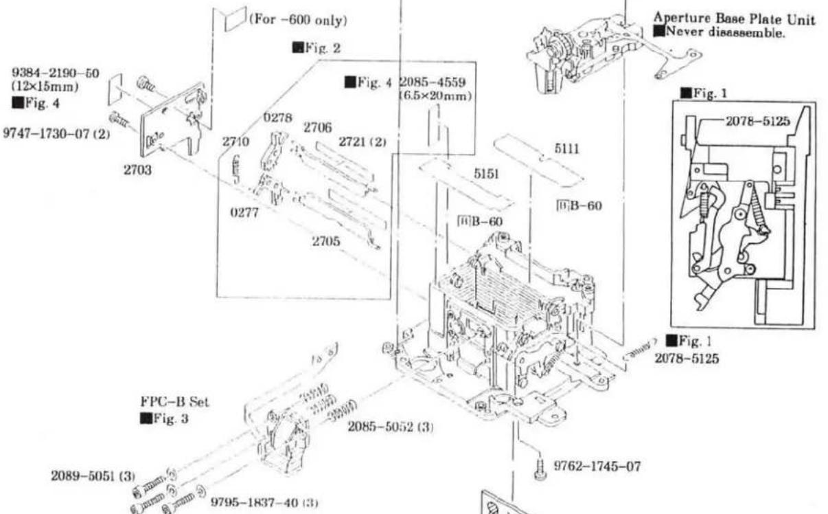
text_image
(For -600 only) Fig. 2 9384-2190-50 (12×15mm) Fig. 4 9747-1730-07 (2) 2703 0278 2706 2721 (2) 2085-4559 (6.5×20mm) 0277 2705 5151 B-60 5111 B-60 Aperture Base Plate Unit Never disassemble. Fig. 1 2078-5125 FPC-B Set Fig. 3 2089-5051 (3) 9795-1837-40 (3) 2085-5052 (3) 9762-1745-07[Hexagon Wrench (1.5)
■Tighten screws until they stop, Then loosen them by two turns.
Fig. 3
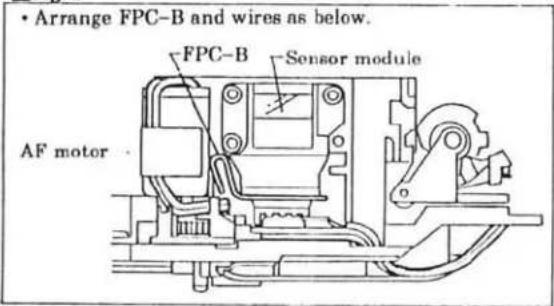
text_image
• Arrange FPC-B and wires as below. FPC-B Sensor module AF motor
2076-5806
■ Use T Mirror Positioner for installation.
■ Use T Mirror Remover for removal.
Leave for 24 hours after affixing.
4 Mirror Box Assembly - II
■Install in the order of ① to ⑦.
text_image
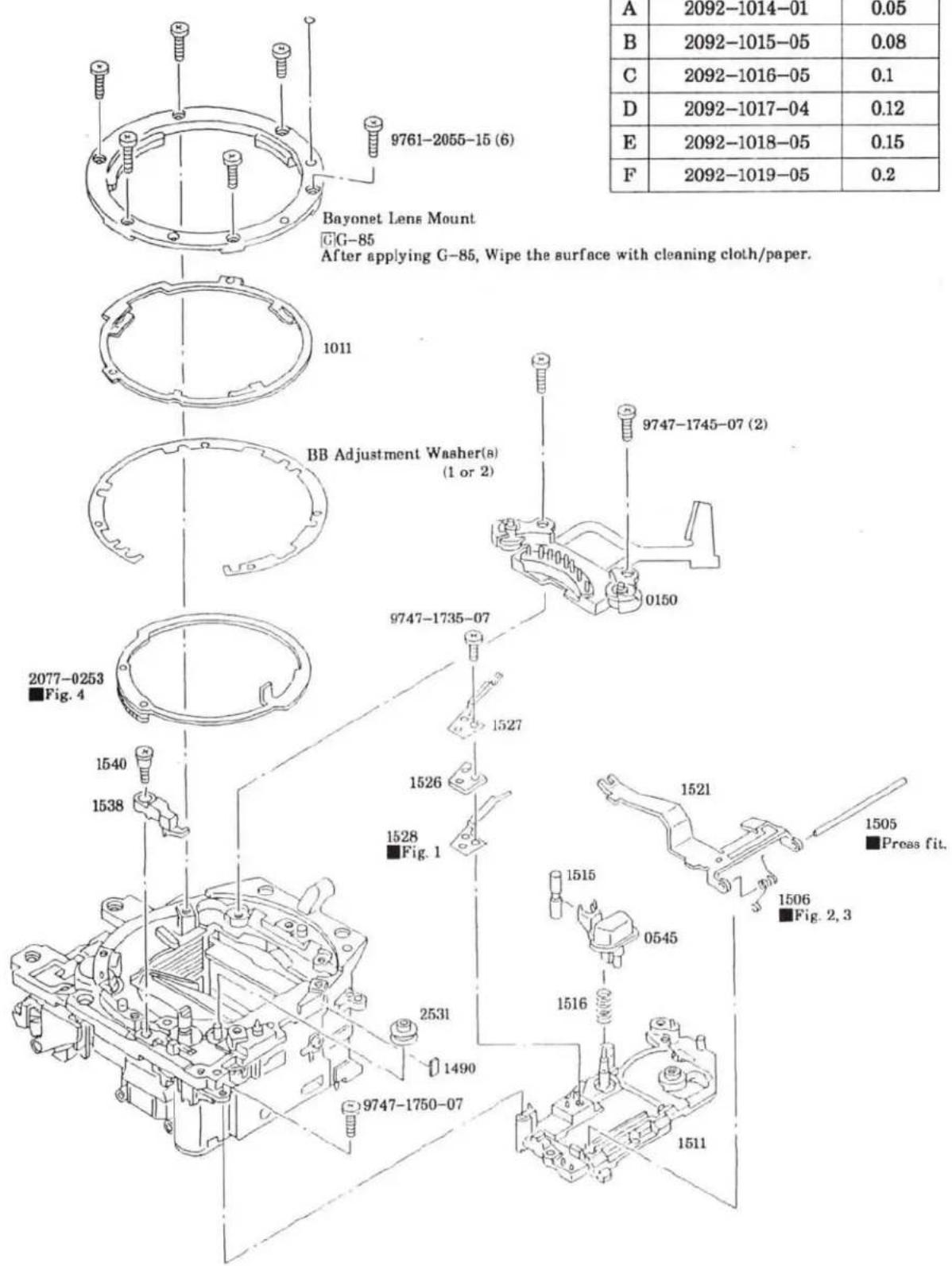
9761-2055-15 (6) Bayonet Lens Mount G-G-85 After applying G-85, Wipe the surface with cleaning cloth/paper. 1011 BB Adjustment Washer(s) (1 or 2) 2077-0253 Fig. 4 1540 1538 1527 1526 1528 Fig. 1 2531 1490 9747-1735-07 9747-1745-07 (2) 0150 1515 0545 1516 1506 Fig. 2, 3 1505 ■Proas fit. 1521 1528 Fig. 1 1540 1538 1516 1511 A 2092-1014-01 0.05 B 2092-1015-05 0.08 C 2092-1016-05 0.1 D 2092-1017-04 0.12 E 2092-1018-05 0.15 F 2092-1019-05 0.2■BB ADJUSTMENT WASHER
| 部品番号 | T=(mm) | |
| A | 2092-1014-01 | 0.05 |
| B | 2092-1015-05 | 0.08 |
| C | 2092-1016-05 | 0.1 |
| D | 2092-1017-04 | 0.12 |
| E | 2092-1018-05 | 0.15 |
| F | 2092-1019-05 | 0.2 |
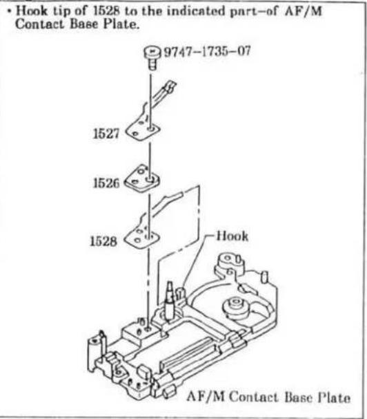
Fig. 1
text_image
• Hook tip of 1528 to the indicated part-of AF/M Contact Base Plate. 9747-1735-07 1527 1526 1528 Hook AF/M Contact Base PlateFig. 2
text_image
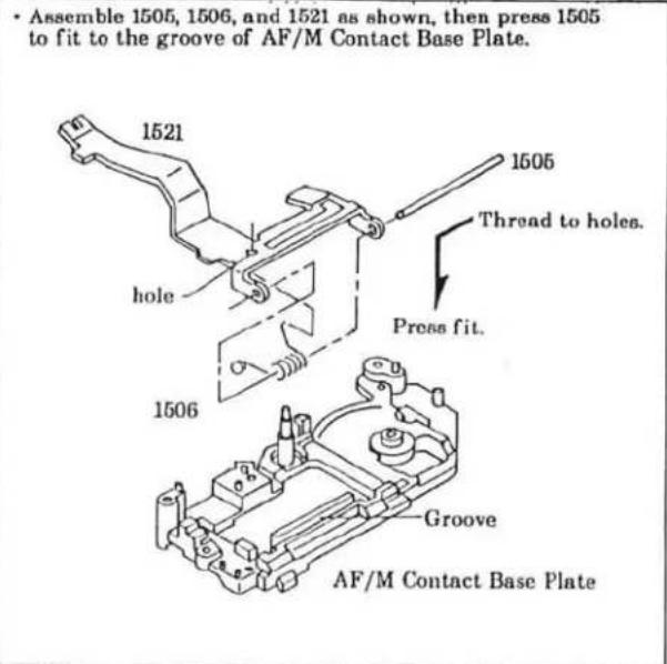
• Assemble 1505, 1506, and 1521 as shown, then press 1505 to fit to the groove of AF/M Contact Base Plate. 1521 hole 1506 1505 Thread to holes. Press fit. 1506 Groove AF/M Contact Base PlateFig. 3
text_image
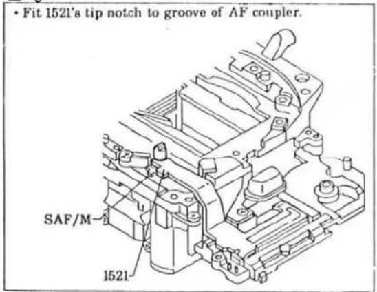
• Fit 1521's tip notch to groove of AF coupler. SAF/M 1521Fig. 4

text_image
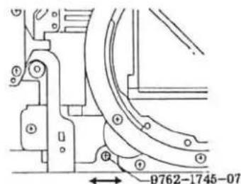
1.Set Aperture Base Plate Unit to aperture-stopped-down position. 2.Install Aperture Ring Set aligning the punch mark with the hole of Aperture Base Plate Unit.■Sw. REL timing adjustment
- Connect Circuit Tester to the position shown in figure.
- Turn Bevel Gear-A in the direction of arrow until it stops.
- By pushing Open Stop Lever slowly, check that the Sw. REL is turned on before the Open Stop Lever is released from the Bevel Gear-A.
- If not, bend part-a to adjust the Sw. REL timing.

text_image
Circuit Tester n Bevel Gear-A Open Stop lever (Black)⑤Penta Prism Unit, FPC-A Set Installation
■Install in the order of ① to ⑤.

text_image
1316 ■Hook to tabs. 4201 ■Wipe the surface with cleaning cloth. 4202 (2) ■Do not touch contacts. 1411 ■Fig. 4 9384-2190-50 (2) (5×5mm) FPC-L 1438 (2) FPC-J 9384-2590-50 (9×15mm) 1438 A FPC-K ■Fig. 3 FPC-A Set ■Fig. 5 (A) ■These parts should be assembled before installing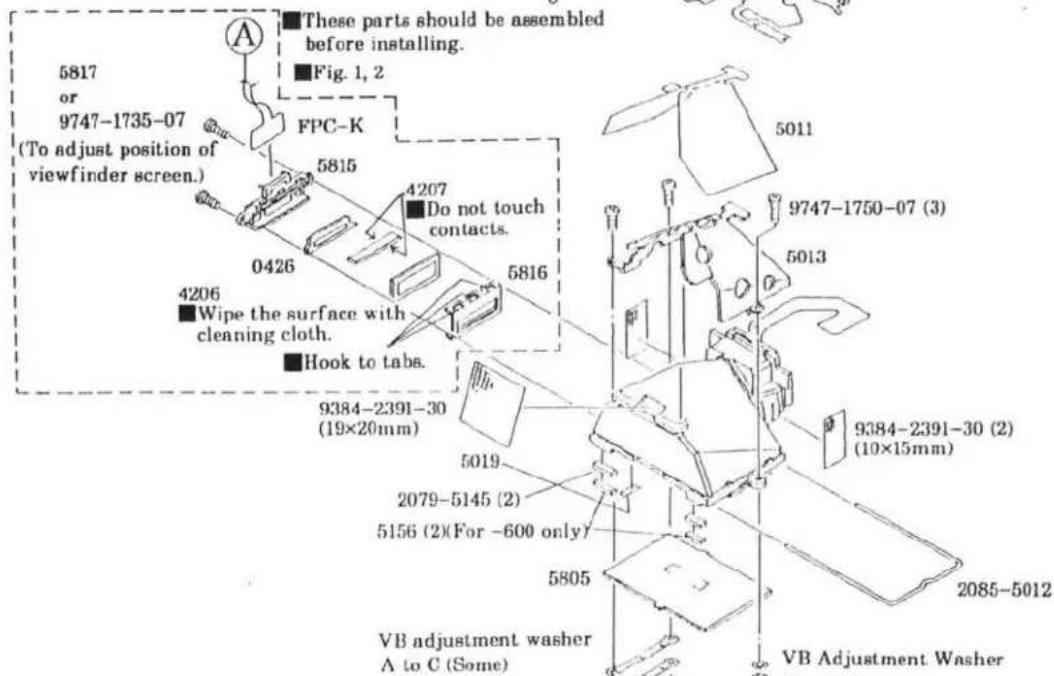
text_image
5817 or 9747-1735-07 (To adjust position of viewfinder screen.) A These parts should be assembled before installing. Fig. 1, 2 FPC-K 5815 4207 Do not touch contacts. 0426 5816 4206 Wipe the surface with cleaning cloth. Hook to tabs. 9384-2391-30 (19×20mm) 5019 2079-5145 (2) 5156 (2)(For -600 only) 5805 VB adjustment washer A to C (Some) 5011 9747-1750-07 (3) 5013 9384-2391-30 (2) (10×15mm) 2085-5012 VB Adjustment Washer■VB ADJUSTMENT PLATE
| 部品番号 | T=(mm) | |
| A | 2092-5025-03 | 0.2 |
| B | 2092-5026-04 | 0.15 |
| C | 2092-5027-04 | 0.1 |
| D | 2092-5035-01 | 0.2 |
| E | 2092-5036-01 | 0.15 |
| F | 2092-5037-01 | 0.1 |

natural_image
Technical line drawing of a mechanical assembly with no visible text or symbolsSee Page 7 to 9.
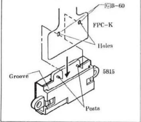
Fig. 1
- Install FPC-K to 5815 by fitting its tip to groove, holes to posts.
text_image
[C]B-60 FPC-K Holes Groove 5815 PostsFig. 2
- Fold FPC-K in the direction of arrows.
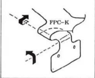
text_image
FPC-KFig. 3
- Fit holes of FPC-K to pins on FPC-A Set, then fold the FPC-K as shown.
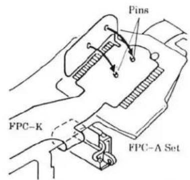
text_image
Pins FPC-K FPC-A SetFig. 4
- Install FPC-K to Shutter-Release Base by fitting to grooves and posts.
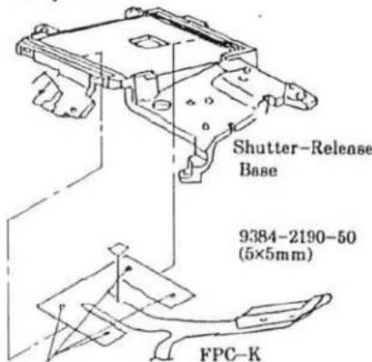
text_image
Shutter-Release Base 9384-2190-50 (5×5mm) FPC-KFit to posts.
Fig. 5
- Fit the indicated part of FPC-A Set to the posts of Shutter-Release Base.
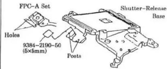
text_image
FPC-A Set Holes 9384-2190-50 (5×5mm) Shutter-Release Base Posts6 Mirror Box Unit Installation
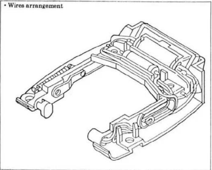
■Arrange wires referring to Fig. 5, 6.
■After installation, check mechanical operation referring to page 13.
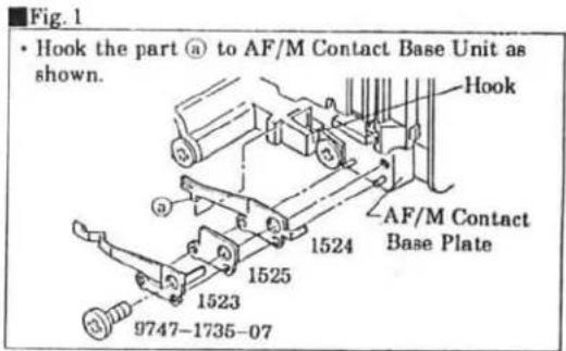
text_image
Fig. 1 • Hook the part (a) to AF/M Contact Base Unit as shown. Hook AF/M Contact Base Plate 1524 1525 1523 9747-1735-07
text_image
9761-2060-07 (2) 1002 9747-1735-07 2075-1062 (2) 9761-1745-07 (2) 9384-2190-50 (5×5mm) Flash Converter PCB Set 9747-1740-07 4502 9747-1760-15 (2) 0139 9761-2065-07 (2) 9384-2391-30 (6.5×20mm) See Page 4 to 6. 2082-4517 FPC-M SET 4513 9747-1745-07 (2) See Page 7 to 11. Shutter Unit Fig. 2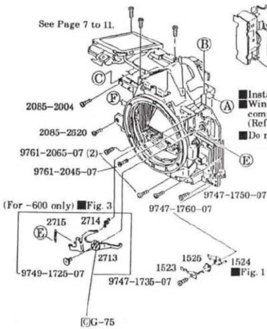
text_image
See Page 7 to 11. 2085-2004 2085-2520 9761-2065-07 (2) 9761-2045-07 (For -600 only) ■Fig. 3 2715 2714 2713 9749-1725-07 9747-1735-07 G-75 9747-1760-07 1523 1525 1524 ■Fig. 1 ■Insta ■Wind comp (Ref ■Do n
text_image
Shutter Unit ■Fig. 2■Install Mirror Box Unit keeping the mirror up.
■ Winding Base Plate Unit should be charged completely before Mirror Box Unit is installed. (Refer to "Installing Winding Base Plate Unit" on page 6.)
Do not pinch wires from Shutter Unit.
Fig. 3 (For -600 only)
- While pushing and holding Panorama Frame Plate-A in the direction of arrow, hook 2715 to the Panorama Frame-A and to 2713 as shown.
- Hook 2714 to 2713 and to post of the AF/M Contact Base Plate.
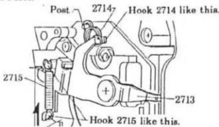
text_image
Post 2714 Hook 2714 like this. 2715 2713 Hook 2715 like this.Panorama Frame-A AF/M Contact Base Plate
Fig. 4
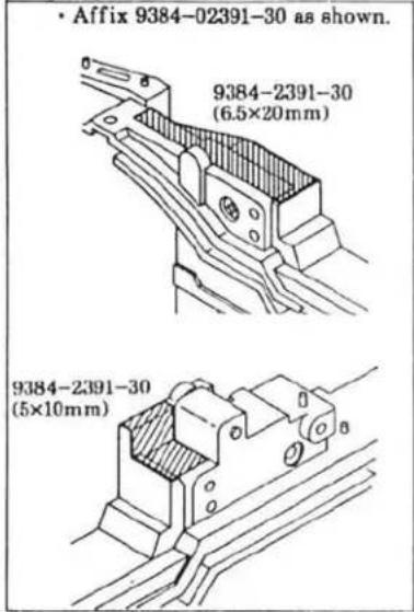
text_image
• Affix 9384-02391-30 as shown. 9384-2391-30 (6.5×20mm) 9384-2391-30 (5×10mm)Fig. 5

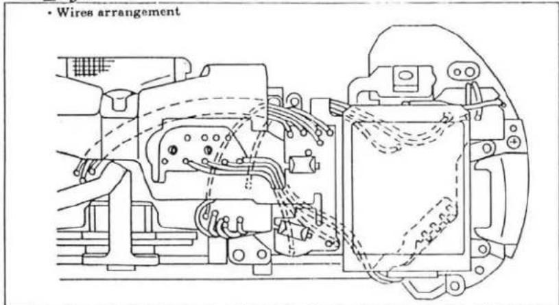
text_image
• Wires arrangementFig. 6
text_image
• Wires arrangement■Mechanical operation check
- Insert Motor axis spanner to hole-d of Aperture Base Plate Set from the bottom of body, then turn the motor manually in both direction to confirm mechanical operation (Fig. 1).
Normal drive (clockwise): Shutter is released then charged.
Reverse drive (counterclockwise): Spool rotates.
2.If Aperture Ring Set doesn't operate smoothly, adjust Screw (9762-1745-07) for smooth operation.
(Fig. 2)
Fig. 1
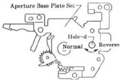
text_image
Aperture Base Plate Set Hole-d Normal ReverseFig. 2
text_image
9762-1745-077 External parts installation
■Install in the order of ① to ⑦.
■Discharge main condenser before disassembly. (See page 2.)
■Be sure to unsolder main Sw. pattern or cut the pattern in FPC-K before installing the Top Cover. (See page 2.)

text_image
1318 9747-1750-15 (2) A B C ④ Cut the part of 0121's contact as shown. 2089-0121 Cut this part-off. ⑥ 2092-1769 (-600) 1402 1418 9762-1740-07 9761-2080-07 9761-2080-07 9384-2190-50 (2) (5×6mm) 1338 D 1482 4014 2075-1062 (2) 2078-3304 (2) 2089-0121 Fig. 1 2078-1023 ② 9761-2050-07 E F 9761-2060-01 9747-1740-15 (2) ① 9747-1765-15 9761-2060-01 9747-1740-15 (2) ③ 1480 1481 9384-2590-50 (9×25mm) ⑤ G-75 ⑦ 1530 1529 (-600) 2082-0120 2082-1205 1422 1312 9748-1730-07 9761-2050-07 E F 9761-2060-01 9747-1740-15 1060 1061 (MALAYSIA) 1 9747-1760-15 1003Back Cover Unit Installation
NON DATE MODEL (-100, -300)

text_image
9747-1730-07 (2) 2078-0114 1111 2076-1112 0117DATE MODEL (-200, -400, -600)
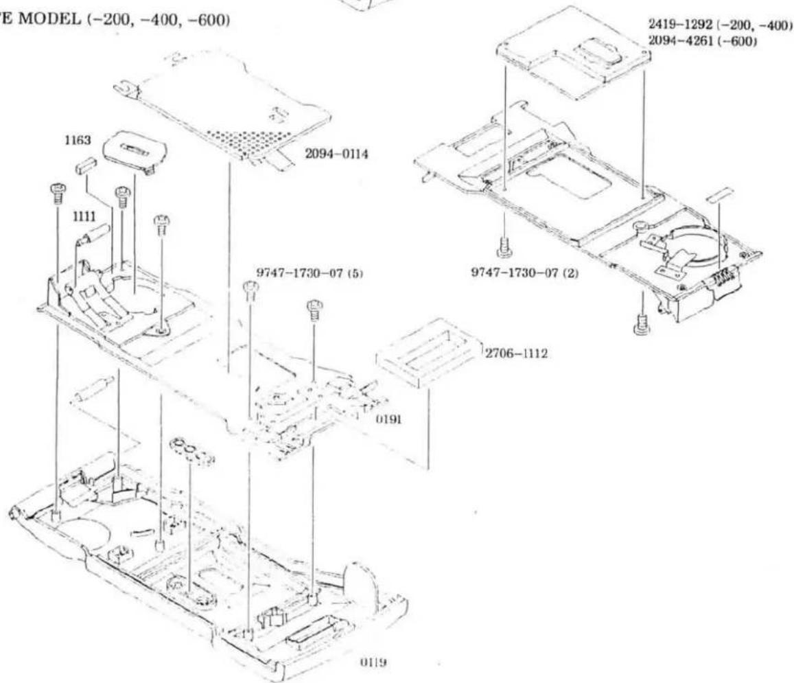
text_image
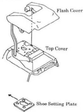
E MODEL (-200, -400, -600) 1163 1111 2094-0114 9747-1730-07 (5) 2706-1112 0191 0119 2419-1292 (-200, -400) 2094-4261 (-600) 9747-1730-07 (2)■ Top Cover Unit Assembly
■Arrange wires referring to Fig. 3 and 6.

text_image
These parts should be assembled before installing. Fig. 5 2085-1611 (2) 2085-1605 4411 Fig. 1 1603 1604 2085-4412 9748-1730-07 1602 1606 9761-1730-07 (3) 0161 Fig. 4 0167 Fig. 2 1608 (2) 1433 1434 1437 1430 1431 (2) 1323 1324 1340 1432 1444 1620 (2) 9762-2060-01 (4) 2085-1616 Fig. 6 4008 2085-1454 Fig. 5 1435 1436 9747-1425-07(2) 2085-1446 2085-1445 9761-1730-07 2085-1635 (9×20mm) Fig. 6 9384-2190-50 (5×10mm) 2085-1453 2085-0145Fig. 1
text_image
• Assemble 1603 and 1605, then insert XE tube. XE tube 1605 1603Fig. 2

text_image
1 Thread tip of 0167 through the part-r of 1602. 2 Hook one end of 1606 to the 0167, the other to tab of 1602. 0167 part-r 1602 Tab 1606Fig. 3
text_image
• Wires arrangementFig. 4

text_image
• Insert 0161 to the part-r of 1602 0161 part-r 1602Fig. 5
- Install the flash assembly to the body with flash down position, then slide Shoe Setting Plate in the direction of arrow to install.
text_image
Flash Cover Top Cover Shoe Setting PlateFig. 6

text_image
• Wires arrangement • 2085-1616 should make contact with FPC-A when the flash is lifted. 2085-1635 (9×20mm) 2085-1616 Solder here.
■Adjustment/check required after repair
☆: Check required after repair
★: Adjustment required after repair
| ADJUSTMENT/CHECK | Mirror Box Unit | Shutter Unit | Aperture Base Plate Unit | RPC-A Set | RPC-B Set | PPA-Print Plate Unit | AF Base Plate Unit | Top Cover Unit | XE Tube PCB Set | ||
| Removed | Replaced | Replaced | Replaced | Replaced | Replaced | Replaced | Replaced | Replaced | Replaced | Replaced | |
| Body back | ★ | ★ | ★ | ★ | ★ | ★ | ★ | ||||
| Viewfinder back | ★ | ★ | |||||||||
| Manual set SS | ★ | ★ | ★ | ||||||||
| Aperture preset | ★ | ★ | ★ | ★ | |||||||
| AE | ★ | ★ | ★ | ★ | ★ | ★ | |||||
| Flash Level | ★ | ★ | ★ | ★ | ★ | ||||||
| Pre-flash level | ★ | ★ | ★ | ★ | |||||||
| Wireless Flash Level | ★ | ★ | ★ | ★ | |||||||
| AP | ★ | ★ | ★ | ★ | ★ | ★ | ★ | ★ | ★ | ||
| APF | ★ | ★ | ★ | ★ | ★ | ★ | ★ | ★ | ★ | ★ | |
| BC-lock voltage | ★ | ||||||||||


■Preparation Before Adjustment-1
■ Equipments required
| : Luminance source | : Contact jig-C for HIT |
| : Shutter tester | : I/F BOX for HIT |
| : EE tester | : Body signal adapter (with X-contact) |
| : 1000mm collimator | : AEF signal adapter |
| : Digital multimeter | : X cable |
| : Strobe tester | : Body Back gauge |
| : Master lens | : Flat plate-A |
| : Xi series PROGRAM(MAXXUM)FLASH | : Dial gauge |
| : DC power supply | : Anvil spacer |
| : Guide No. adjusting jig | : BB adjustment mount |
| : 2CR5 type power supply adapter | : Reflection paper |
| : 2CR5 type power supply adapter for B.C. adjustment | : Hexagon wrench (1.5) |
| : HIT controller | |
| : ROM PACK for 2092 | for more than 1 day) |
※GAME BOY is a registered trade mark owned by Nintendo Co. Ltd.
※Jig numbers and models are listed in Tools and Instrument (P. 39).
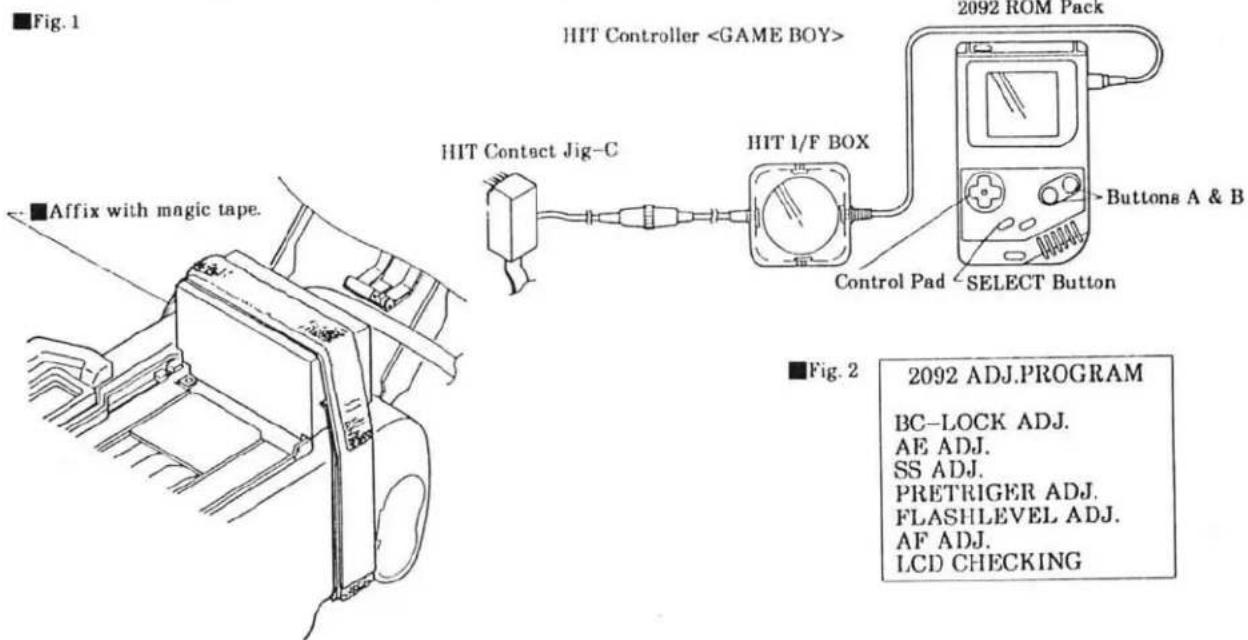
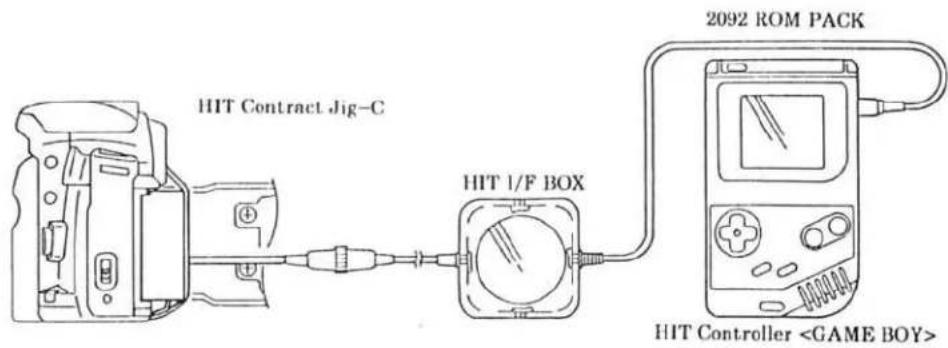
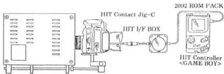
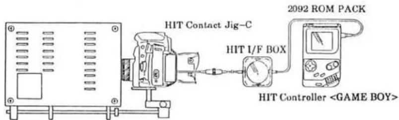
■Instruction for using HIT system
※Make sure that no battery is installed in camera before setting up the HIT system.
- Set up the equipments as in Fig. 1.
- Attach HIT Contact Jig-C so its probes contact with the check lands of the camera, then affix them with magic tape.
- Insert a battery or connect 2CR5-Type Power Supply Adapter to the camera, then turn the camera and HIT Controller on. Main menu appears in LCD (Fig. 2).
- Select an item using Control Pad so the selected item will appear in a black box. Then press SELECT Button to enter.
※After setting up the equipments, perform "All LCD displays on check" (P. 33) to check for correct connection before starting any adjustment/check.
text_image
■Fig. 1 HIT Controller2092 ROM Pack


text_image
ButtonBC-LOCK ADJ.
AE ADJ.
SS ADJ.
PRETRIGER ADJ.
FLASHLEVEL ADJ.
AF ADJ.
LCD CHECKING
■Body Back Adjustment- I
■ Equipments required
: Body Back Gauge
: Flat Plate-A
: Dial Gauge
: Anvil Spacer
: BB Adjustment Mount
Procedure
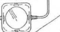
- Attach Anvil Spacer to Dial Gauge. (Fig. 1)
- Attach BB Adjustment Mount to camera.
- Set the Dial Gauge as in Fig. 2, then measure distance between guide rail and BB Adjustment Mount surface as in Fig. 3.
- Subtract thickness of the BB Adjustment Mount (written on its surface) from the measured value, so the body-back of the camera is obtained.
Measured value - thickness of BB Adjustment Mount = Body back
※Add or subtract BB adjustment washer so that the body back meets standard below. (See table below for the washer thickness.)
- After adjustment, perform Body back Adjustment- II (P. 21).
Standard 44.710±0.015
■BB ADJUSTMENT WASEHR
| 部品番号 | T=(mm) | |
| A | 2092-1014-01 | 0.05 |
| B | 2092-1015-05 | 0.08 |
| C | 2092-1016-05 | 0.1 |
| D | 2092-1017-04 | 0.12 |
| E | 2092-1018-05 | 0.15 |
| F | 2092-1019-05 | 0.2 |
Fig. 1

text_image
Dial Gauge Anvil Spacer AnvilFig. 2
text_image
43.70mm Body Back Gauge 45.70mm ■Fig. 3 44.70mm BB Adjustment Mount■Body Back Adjustment— II
※Body Back Adjustment- I (P. 20) should be completed before starting.
■ Equipments required
: HIT Controller
: 2092 ROM PACK
: HIT Contact Jig-C
: HIT I/F BOX
Procedure
- Set the equipments as in Fig. 1
- Select "AF ADJ." in the main menu with Control Pad, and press SELECT Button.
- Select "B.B. ADJ." in AF adjustment menu, and press the SELECT Button.
- Press Shutter-Release Button partway down. ※Previous Body-back value before adjustment (P. 20) is displayed.
- Select the number (body-back value) using Control Pad. And press upper/lower Control Pad to set the body-back value adjusted in Body Back adjustment-1 (P. 20). ※The number changes in 0.002-stop increments by each press of the Control Pad.
- Press SELECT Button.
- Press Shutter Release Button partway down. "COMPLETE" appears.
- Press SELECT Button so the displays are replaced with the AF adjustment menu.
Fig. 1
text_image
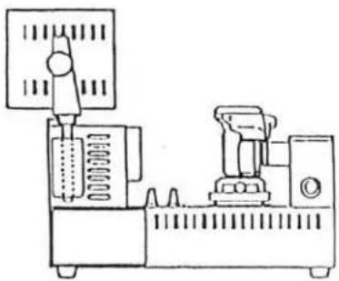
HIT Contract Jig-C HIT 1/F BOX 2092 ROM PACK HIT Controller■Viewfinder Back Adjustment
■ Equipments required
: 1000mm collimator
: Master lens
: Hexagon wrench (1.5)
Procedure
- Set the camera so that the chart is positioned at the center of Viewfinder, then set master lens's Focus Ring to . (Fig. 1)
- Check that the chart is in focus. If not, adjust mirror position as follows.
- Remove the lens from the camera.
- Holding the mirror up with a finger, move VB adjuster up and down so the chart is in focus.
- Release the shutter several times, then turn the lens' Focus Ring until stops at , and check that the chart is in focus.
text_image
Fig. 1 Master Lens 1000mm Collimator
text_image
Fig. 2 Hexagon wrench (1.5) In case of front focus In case of rear focus■Hold mirror with a finger as shown to adjust viewfinder back.
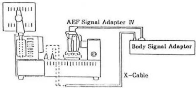
■Manual SS & X-Sync. Time-Lag Check
■ Equipments required
: Shutter tester
: Body signal adapter (with X-contact)
:X-cable
: AEF signal adapter IV
■Manual SS check
- Set the equipments as in Fig. 1.
- Check that the reading is within the tolerance in Table-1.
■X-sync. time-lag adjustment
- Set the camera to Shutter Tester as in Fig. 2.
- Check that X-sync. time lag is within the standard in Table-2.
Fig. 1
natural_image
Technical line drawing of a mechanical device with no visible text or symbolsFig. 2
flowchart
graph TD
    A["Input"] --> B["Analog Inverter"]
    B --> C["AEF Signal Adapter IV"]
    C --> D["Body Signal Adaptor"]
    D --> E["X-Cable"]
    style A fill:#f9f,stroke:#333
    style E fill:#ccf,stroke:#333
Table-1
| SS | Reference value at range-B (ms) | Tolerance at range-B (ms) | Exposure unevenness |
| 1/2000 | 0.488 | 0.311 to 0.766 | Difference between max. and min. of range-A,-B, -C should be 0.6EV or smaller |
| 1/1000 | 0.977 | 0.667 to 1.430 | |
| 1/125 | 7.81 | 6.34 to 9.62 | |
| 1/2 | 500 | 467 to 536 |
Table-2
| SS | Measured item | Standard (ms) |
| 1/90 | X-contact delay time | 0.4 to 0.9 |
| From X-contact on to 2nd curtain appearance | 2.4 or more |
AE Level Check
■ Equipments required
- Set the camera and equipments as in Fig. 1.
- Check that the exposure values meet the tolerance in table.
※When using MODEL L-222 or L-223, apply the value in brackets ( ).
natural_image
Pure electrical circuit lines without any symbolsLuminance source: K value: L3
Camera: ISO: 100 Exposure mode: See table above. Aperture: See table above. Focus mode: M
| Order | Luminance | Exposure mode | Shutter speed | Aperture | Tolerance |
| 1 | EV6 (EV5) | A | --- | F5.6(F8) | 0±1.0EV |
| 2 | EV10 (EV11) | ||||
| 3 | EV15 (EV15) | ||||
| 4 | EV6 (EV5) | P | --- | --- | |
| 5 | EV10 (EV11) | ||||
| 6 | EV15 (EV15) | ||||
| 7 | EV10 (EV11) | S | 1/125 | --- | |
| 8 | 1/30 |
Aperture Control Check
■ Equipments required
- Set the camera and equipments as in Fig. 1.
- Release the shutter to check the pointer of EE Tester indicates within 0±0.3EV.
※Reading may be above/below this range depending on the lens' aperture tolerance.

natural_image
Simple line drawing of an electrical connection setup with a device and analog meter (no text or symbols)Luminance source: K value: L3 Luminance: EV11 Camera: Exposure mode: M Aperture: F5.6 Shutter speed: Bulb Focus mode: M Master Lens: Focus Ring: ∞ EE tester: K value: L3 F Value: 5.6 ASA: F MEAS, CALF : CALF
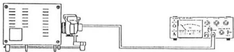
■Flash Level Check (Using strobe tester )
■ Equipments required
: Strobe tester
: Master lens
: xi-series PROGRAM (MAXXUM) FLASH
: Reflection paper
: Film (Kodacolor Gold 100 exposed in a room for more than 1 day)
Procedure
※Perform this check in a dark room
-
Set the camera and equipments as in Fig. 1
-
Turn the flash on and check that the flash ready signal glows.
-
Hold Strobe Tester beside the camera (Fig. 1). And looking through viewfinder of Strobe Tester, align eye point in the viewfinder to the center of Reflection Paper.
-
Press Strobe Tester's measuring button to set the tester to the stand by condition ("NON.C" blinks.), then release the shutter.
-
Check that the reading of Strobe Tester is within standard (F5.6±0.5EV).
Fig. 1
text_image
2m from film plane Reflection paperCamera:
With film loaded
Exposure mode:A
ISO:100
Aperture:F 5.6
Master Lens
Strobe Tester:
Reflection type receiver
Mode:NON.C
Flash:
Power level selector:H
■ Make uniform the height of center of reflection paper and optical axis of lens.
■ Position the camera so that the center of reflection paper can be seen at the center of viewfinder.

Manual set SS Adjustment
※Perform this adjustment before adjusting aperture preset (P. 27)
■ Equipments required
-
Set the camera to Shutter Tester. (Fig. 1) ※The camera's SPC-2 Holder may be in the way of Shutter Tester's light receptor. Set the camera off-center so that the light receptor is not obstructed by the SPC-2 Holder.
-
Set shutter speed to 1/2000 sec. and release the shutter several times. Calculate center value of the range-B. ※If the center value is out of standard, perform adjustment as follows.
- Set the equipments as in Fig. 2.
- Select "SS ADJ." in the main menu with Control Pad, then press SELECT Button.
- Select "536" using Control Pad.
- Set the center value ( S) obtained at procedure 2 using Control Pad and Button A or B, then press SELECT Button.
*Pressing upper/lower Control Pad while pressing and holding Button A:8μS Pressing upper/lower Control Pad while pressing and holding Button B:104μS
-
Press Shutter Release Button partway down. "COMPLETE" appears.
-
Press SELECT Button. Displays are replaced with the main menu.
Standard: 0.311 - 0.766
natural_image
Technical line drawing of a mechanical device with no visible text or symbolsLight receptor of Shutter Tester

text_image
SPC-2 holder■Set the camera off center so the light receptor is not obstructed by SPC-2 Holder.
Fig. 2

text_image
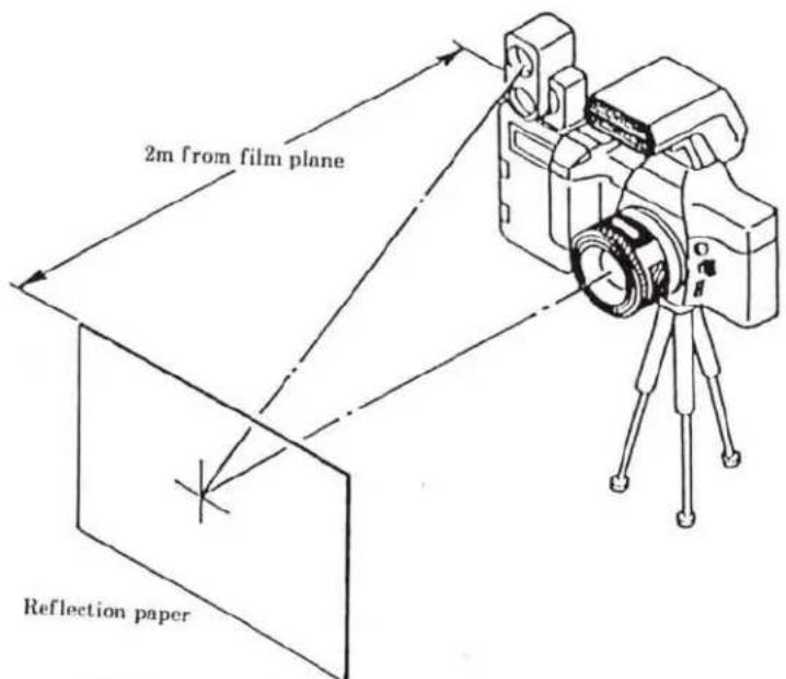
HIT Contact Jig-C HIT I/F BOX 2092 ROM PACK HIT Controller■Aperture preset Adjustment
※Manual set SS adjustment (P. 26) should have been completed.
■ Equipments required
- Set the equipments as in Fig. 1.
- Select "PRETRIGGER ADJ." in the main menu with Control Pad, and press SELECT Button.
- Check that the built-in flash is down, and set Luminance Source to EV10, then press SELECT Button to enter.
- Press Shutter-Release Button partway down. Shutter speed and aperture displays appear in both camera's and HIT controller's LCD. Check that they are the same.
- Release the shutter and see whether the value in EE Tester is 0.35EV or more, or less than 0.35EV. ※If the value is -0.35EV or more, select "-0.35EV OR OVER", if it is less than -0.35EV, select "UNDER -0.35EV" using Control Pad, and press SELECT Button.
- Release the shutter. Check that value in EE tester is changed by 0.5EV from the value obtained at procedure-5. If so, select "YES", and press SELECT Button. Displays are replaced with next measuring point. ※If the value is not changed by 0.5EV, select "NO", and press SELECT Button. Then repeat procedure-6 until you can select "YES".
- Repeat procedure 4, 5, and 6 for four of the measuring points. (Fig. 2)
- "COMPLETE" appears when adjustment is completed.
- Press SELECT Button. Displays are replaced with the main menu.
Fig. 1
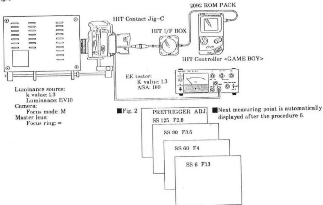
text_image
Luminance source: k value: 1.3 Luminance: EV10 Camera: Focus mode: M Master lens: Focus ring: ∞ HIT Contact Jig-C HIT 1/F BOX 2092 ROM PACK HIT ControllerAE Adjustment
■ Equipments required
- Set the equipments as in Fig. 1
- Select "AE ADJ." in main menu using Control Pad, and press SELECT Button.
- Select "AE ADJ." in AE adjustment menu using Control Pad, and press SELECT Button.
-
Set Luminance Source to EV6, press SELECT Button.
*Panorama model -600 should be set to normal frame. -
Press Shutter-Release Button partway down.
-
Set Luminance Source to EV15, press SELECT Button.
-
Press Shutter-Release Button partway down.
-
Select panorama or normal model as follows.
※For -600 model:
①Select "PANORAMA MODEL", and press SELECT Button.
②Set Luminance Source to EV15, press SELECT Button.
③Set the camera to panorama frame.
④Press Shutter-Release Button partway down. "Complete" appears when adjustment is completed.
※For other models
①Select "NORMAL MODEL", and press SELECT Button. "COMPLETE" appears when adjustment is completed.
- Press SELECT Button. Displays are replaced with the AE adjustment menu.
-
Select AE CHECK in the AE adjustment menu with Control Pad, and press SELECT Button.
-
Set luminance source to EV10.
-
Press Shutter-Release Button partway down. Displays as Fig. 2 appears.
-
Check that value in each cell is within EV±0.3. (Fig. 2)
※Also check with EV6 and EV15.
- Press SELECT Button. Displays are replaced with the AE adjustment menu.
Fig. 1
text_image
2092 ROM PACK HIT Contact Jig-C HIT I/F BOX HIT ControllerLuminance source:
K Value: 1.3
Luminance: EV 6, 10, 15
Camera:
Focus mode: M
Master Lens:
Focus ring: ∞
Fig. 2
Example: EV10

text_image
10.0 10.1 10.1 10.0 10.0 10.1 10.0 10.1 10.0 10.1 10.0 10.1 10.1■Flash Level Adjustment
■ Equipments required
- Set the equipments as in Fig. 1.
- Select "FLASH LEVEL ADJ." in main menu with Control Pad, press SELECT Button.
- Select "FLASH LEVEL ADJ." in flash level adjustment menu with Control Pad, press SELECT Button.
- Set Luminance Source to EV10. And press SELECT Button.
- Press and hold Shutter-Release Button partway down until "COMPLETE" appears. Shutter is automatically released five times before the "COMPLETE" appears.
- Press SELECT Button. Displays are replaced with the flash level adjustment menu.
- Select "FLASH LEVEL CHECK" in the flash level adjustment menu using Control Pad, and press SELECT Button.
- Set Luminance Source to EV10. Press SELECT Button.
- Press and hold Shutter-Release Button partway down until "COMPLETE" appears. Shutter is automatically released three times before the "COMPLETE" appears.
※Check that the reading at either of ISO 50, 100 and 400 is within ±0.4EV. (Fig. 2)
- Press SELECT Button. Displays are replaced with the flash adjustment menu.
Fig.1
flowchart
graph LR
    A["HIT Contact Jig-C"] --> B["2092 ROM PACK"]
    B --> C["HIT Controller <GAME BOY>"]
    D["HIT I/F BOX"] --> C
Luminance source:
K value: 1.3
Luminance: See above.
Camera:
Focus mode: M
Master Lens:
Focus ring: ∞
■Attach Reflection paper to unnecessary pressure plate to be discarded. And hold them at the camera back on film plane.
Fig. 2
FLASH LEVEL CHECK
COMPLETE
50 -0.18EV
100 -0.18EV
400 -0.18EV
MENU
■Pre-Flash Level Adjustment
■ Equipments required
: Strobe Tester
: Guide No. Adjusting Jig.
: HIT Controller
: HIT Contact jig-C
: HIT I/F box
: 2092 ROM PACK
Procedure
- Set the equipments as in Fig. 1.
- Select "FLASH LEVEL ADJ." in the main menu using Control Pad, and press SELECT Button.
- Select "PREFIRE ADJ." in flash level adjustment menu using Control Pad, and press SELECT Button.
- Press Shutter-Release Button partway down.
- Select "FIRE" with Control Pad, and press SELECT Button.
- Press Shutter-Release Button partway down so built-in flash fires. Check that reading in Strobe Tester is within standard range.
※If not, perform adjustment as follows.
- Press Control Pad at the right or left to adjust flash output.
To increase flash output: Press the right of Control Pad.
To decrease flash output: Press the left of Control Pad.
- Repeat procedure 5, 6, and 7 until the reading meets the standard.
- Select "MENU" with Control Pad and press SELECT Button. Displays are replaced with the flash level adjustment menu.
Standard range: F0.8+0.2 to F11+0.2
Fig. 1

text_image
Guide No. adjusting jig HIT Contact Jig-C HIT I/F BOX 2092 ROM PACK HIT Controller
■Wireless Flash Level Adjustment
■ Equipments required
: Strobe tester
: Guide No. adjusting jig
: HIT Controller
: HIT Contact Jig-C
: HIT I/F BOX
: 2092 ROM PACK
Procedure
- Set the equipments as in Fig. 1.
- Select "FLASH LEVEL ADJ." in main menu using Control Pad, and press SELECT Button.
- Select "W-LESSFIRE ADJ." in flash level adjustment menu using Control Pad, and press SELECT Button.
- Press Shutter Release Button partway down.
- Select "FIRE" with Control Pad, and press SELECT Button.
- Press Shutter-Release Button partway down so that the built-in flash fires. Check that reading in Strobe Tester is within standard range.
※If not, perform adjustment as follows.
- Press the right or left of Control Pad to adjust flash output.
To increase flash output: Press the right of Control Pad.
To decrease flash output: Press the left of Control Pad.
- Repeat procedure 5, 6, and 7 until the reading meets the standard.
- Select "MENU" with Control Pad, and press SELECT Button. Displays are replaced with the flash level adjustment menu.
Standard F2.8 to F4
Fig. 1

flowchart
graph LR
    A["Guide No. adjusting jig"] --> B["HIT Contact Jig-C"]
    B --> C["HIT I/F BOX"]
    C --> D["2092 ROM PACK"]
    D --> E["HIT Controller <GAME BOY>"]
    F["Strobe Tester"] --> B
    G["Camera: Built in flash: Raised"] --> B
    H["Strobe tester: Flat type receiver"] --> B
    I["Mode: NON.C"] --> B
B.C. Lock Voltage Adjustment
■ Equipments required
: DC Power Supply
: Digital Multimeter
: 2CR5 Type Power Supply Adapter for B.C. adjustment
: HIT Controller
: HIT Contance Jig-C
: HIT I/F BOX
: 2092 ROM PACK
Procedure
- Set the equipments as in Fig. 1.
- Select "BC-LOCK ADJ." in main menu using Control Pad, and press SELECT Button.
- Press SELECT Button, then Shutter-Release Button partway down.
- Set DC Power Supply to 5.05V, and press SELECT Button.
- Press Shutter-Release Button partway down twice. "COMPLETE" appears.
- Select "MENU" with Control Pad, and press SELECT Button. Displays are replaced with main menu.
- Check that B.C. lock operates at the standard voltage as below.
Standard voltage: 4.75V
Fig. 1

text_image
HIT Contact Jig-C DC Power Supply 5.05V HIT I/F BOX 2092 ROM PACK HIT Controller2CR5 Type Power Supply Adapter for B.C. Adjustment
■All LCD Displays On Check
■ Equipments required
: HIT Controller
: HIT Contaxt Jig-C
: HIT I/F BOX
: 2092 ROM PACK
Procedure
- Set the equipments as in Fig. 1.
- Select "LCD CHECKING" in main menu using Control Pad, and press SELECT Button.
- Press Shutter-Release Button partway down. All displays appear in Body Data Panel.
- "COMPLETE" appears in LCD of HIT Controller.
- Press SELECT Button so that displays are replaced with the main menu.
Fig. 1

text_image
HIT Contact Jig-C HIT I/F BOX 2092 ROM PACK ILL.HIT Controller■Preparation Before Adjustment-2 (AF adjustment)
※After replacing FPC-A or FPC-B, or parts attached to mirror or mirror box, and when users point out poor focus, be sure to perform adjustment ① (P. 35) to ③ (P. 37).
Items to be confirmed before AF adjustment
※Check the following items before performing AF adjustment.
- Body back and Viewfinder back should have been checked and adjusted.
- All external parts except for Bottom Cover Unit should be installed.
- When CCD sensor module is out of position after replacing FPC-B, tighten three AF adjusting screws (2089-5051) until they stop, then evenly loosen them by two turns.
■ Equipments required
*See "Tools & Instruments (P. 39) for model and jig-numbers.
: 1000mm collimator
: AF Master lens
: AF Chart- VII for 2085
(See P. 29 of 2085 Service Manual)
: AF Chart- VII
: HIT controller
: 2092 ROM PACK
: HIT Contact Jig-C
: HIT I/F BOX
: AF-Y.P adjuster
: AF tripod attachment II
: Grip ring
: Hexagon bar wrench or
Hexagon screwdriver
: Flood lamp
(having color temperature of 2800°K)
Fig. 1
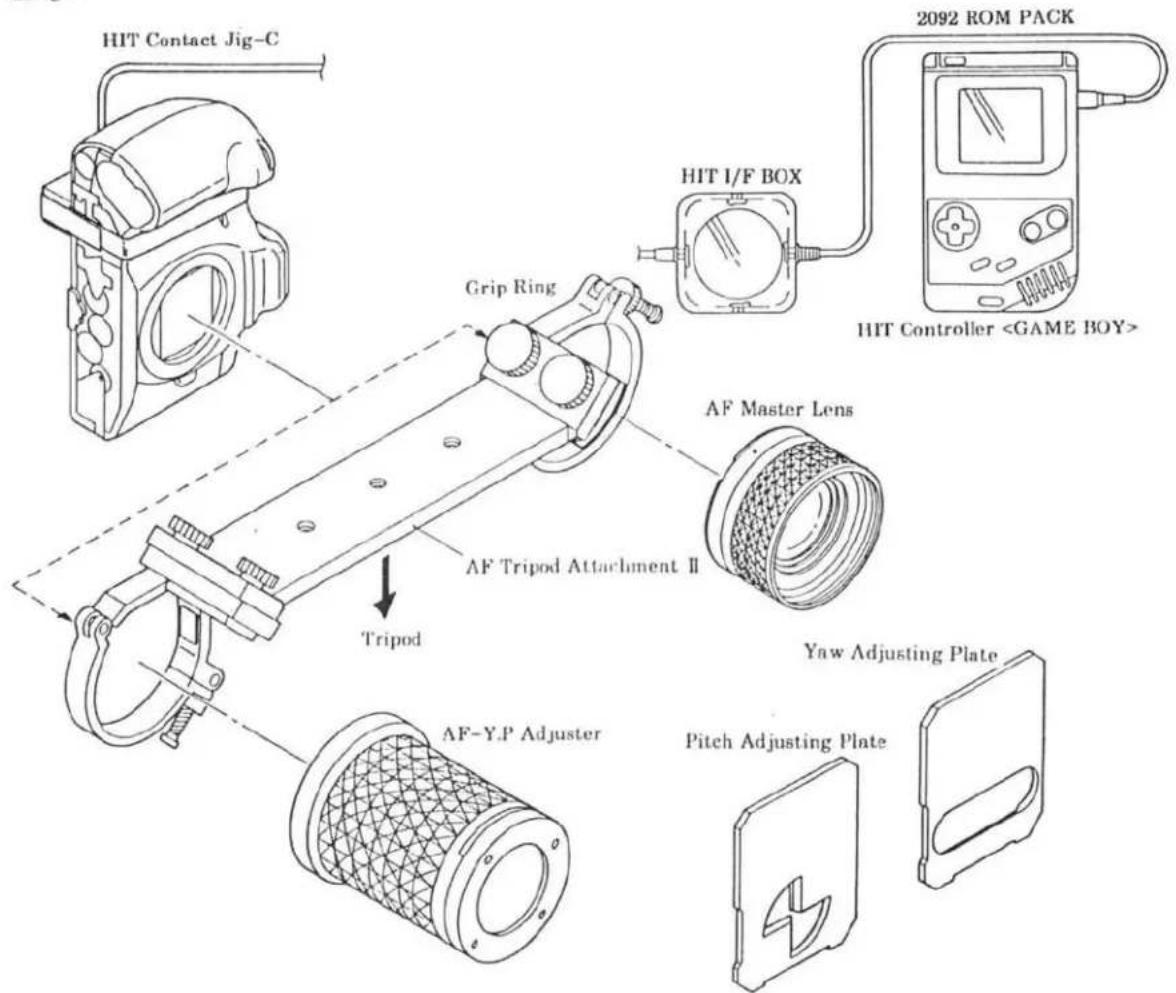
text_image
HIT Contact Jig-C Grip Ring HIT I/F BOX 2092 ROM PACK HIT Controller①AF Area Adjustment
Procedure
- Set up HIT system, and set camera and AF chart- VIII as in Fig. 1.
- Select "AF ADJ." in main menu using Control Pad, and press SELECT Button.
- Select "AREA ADJ." in AF adjustment menu using Control Pad, and press SELECT Button.
- Press Shutter-Release Button partway down so wavy lines and value appear in display of HIT Controller. Check that the wavy lines are like the one in Fig. 2 and the value is within standard below. (Fig. 2)
※If not, perform adjustment as follows.
- Press SELECT Button. Displays are replaced with AF adjustment menu.
※Shutter cannot be released with the displays as Fig. 2.
-
Set the camera's shutter speed to bulb, then adjust Sub Mirror position using Hexagon Bar Wrench (15) as in Fig. 3.
-
Repeat procedure 3 and 4 until the value is within the standard.
-
Press SELECT Button. Displays are replaced with the AF adjustment menu.
Fig. 1

text_image
Camera: Focus mode: M : M AF Master Lens Lens mount surface 1,955mm AF chart- VIII Looking through viewfinder, set the chart so that its four dots align with corners of focus frame.Fig. 2
text_image
101Standard 100±4
Fig. 3

text_image
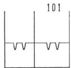
Hexagon bar wrench (1.5) Camera: Shutter speed: Bulb②Pitch, Yaw Adjustment
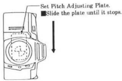
Light up the chart with a flood lamp during Pitch, Yaw adjustment.
Procedure
■Pitch adjustment
- Insert Pitch Adjusting Plate to Y.P Adjuster. (F.)
- Select "AF ADJ." in main menu using Control Pad, and press SELECT Button.
- Select "PITCH.YAW ADJ." in AF Adjustment menu with Control Pad, and press SELECT Button.
- Press Shutter-Release Button partway down.
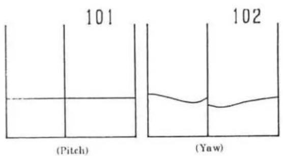
- Turn Pitch Adjusting Screw as in Fig. 4 so that the value in the HIT controller display is within standard range (0090–0110).
■Yaw adjustment
- Insert Yaw Adjusting Plate to Y.P Adjuster. (Fig. 3)
- Turn Yaw Adjusting Screw as in Fig. 4 so that the value in the HIT Controller display is within standard range (0083–0110).
- Press SELECT Button. The displays are replaced with AF adjustment menu.
Check after adjustment
- Check AF area referring to page 35. If required, perform "① AF area adjustment" and "② Pitch, Yaw adjustment" repeatedly until all readings meet standards.
Fig. 1
text_image
Set Pitch Adjusting Plate. ■Slide the plate until it stops.Fig. 2
text_image
101 (Pitch) 102 (Yaw)Fig. 3

text_image
Set Yaw Adjusting Plate. ■Slide the plate until it stops.Fig. 4

text_image
AF Adjusting Screw (for Yaw adjustment) AF Adjusting Screw (for Pitch adjustment)③EZ Adjustment
Procedure
- Set up the HIT system, and set camera and AF chart- VII as in Fig. 1.
- Select "AF ADJ." in main menu using Control Pad, and press SELECT Button.
- Select "EZ ADJ." in AF adjustment menu using Control Pad, and press SELECT Button.
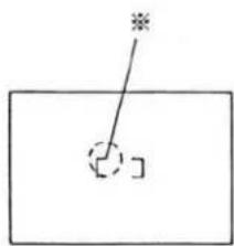
- Looking through viewfinder, align the left of focus frame (Fig. 2) with measuring point I. Then press SELECT Button.
- Press and hold Shutter-Release Button partway down until the next measuring point appears in the display.
- Repeat procedure 4 and 5 for each measuring point of I to L. "COMPLETE" appears when all measuring points are adjusted.
- Press SELECT Button. Displays are replaced with the AF adjustment menu.
- Select "EZ CHECK" in the AF adjustment menu using Control Pad, and press SELECT Button.
- Looking through viewfinder, align the left of focus frame (Fig. 2) with measuring point K.
- Press Shutter-Release Button partway down.
※Check that the displayed value is within standard range (±30). (Fig. 3). - Press SELECT Button. Displays are replaced with the AF adjustment menu.
Fig. 1

text_image
Camera: Focus mode: M AF Master Lens 1,955mm Lens Mount Surface AF chart- VII L K J IFig. 2
natural_image
Simple line drawing of a rectangle with a diagonal line and a small square cutout, no text or symbols present.Fig. 3

text_image
15■Error code on HIT Controller
Error code list
| Item | No. | Meaning | Cause |
| B.C. lock voltage adjustment | 10 | A/D conversion value at Battery check is incorrect. | ·Voltage is wrongly set.·Resistance of Power Supply Adapter is defective.·Resistor for B.C. dummy current is defective, triggering failure |
| AE adjustment | 20 | Picture frame is wrongly set. | ·Picture frame is wrongly set.·SPANO is defective. |
| 21 | Little difference between EV6 and EV15 is detected. | ·Luminance source is wrongly set.·SPC is disconnected. | |
| Flash level adjustment | 30 | Flash level is incorrect. | ·Luminance source is wrongly set.·SPC is disconnected.·Reflection paper isn't set.·Aperture mechanism is defective. |
| Pre-flash level adjustment | 40 | SFLD isn't turn ON. | ·Flash remains down.·SFLD is disconnected. |
| Wireless flash level adjustment | |||
| Aperture preset adjustment | 50 | Aperture preset is out of adjustable range. | ·Aperture Base Plate Unit is defective. |
| EZ adjustment | 61 | Contrast is low. | ·Chart is out of position.·Chart is too close/far.·CCD is defective. |
Tools & Instruments
■Luminance source
■EE tester
■Shutter tester
■1000mm collimator
■Digital multimeter
■DC power supply < ^*524B , *524C, MTR18-2>
■Strobe tester
xi-series PROGRAM(MAXXUM)FLASH
■Master Lens <2072-0001-75>
■AF Master Lens <2072-0006-75>
■HIT Controller (GAME BOY) <7981-5001-01>
■ROM PACK for 2092 <7981-5001-56>
■Contact Jig-C for HIT <7981-5001-13>
■I/F Box for HiT <7981-5001-32>
■AF Chart- VIII <2085-0001-75>
■AF Chart- VII for 2085 <2082-0003-75>
■Body Signal Adapter IV (With X-contact)
■ AEF Signal Adapter <7981-2014-34>
■X Cable <7981-2014-16>
■Guide No. adjusting jig <2082-0005-75>
■Motor axis spanner <2078-0421-75>
■2CR5 type power supply adapter <7981-1018-51>
Contact Jig-C for HIT <7981-5001-13>

natural_image
Simple line drawing of a plug with a cable, no text or symbols presentROM PACK for 2092
<7981-5001-56>

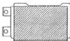
natural_image
Simple line drawing of a rectangular box with three circular holes and a downward arrow (no text or symbols)■2CR5 type power supply adapter for B.C. adjustment <7981-2203-02>
■AF tripod attachment <2072-0003-76>
■AF-Y.P adjuster <2076-0006-75>
Grip ring <7983-9004-01>
■Mirror remover <2071-5806-75>
■Mirror positioner <2072-5151-75>
■BB adjustment mount <7982-2007-01>
■Anvil spacer <7982-2001-31>
■Body back flat plate-A <7982-2004-01>
■Body back gauge <7982-2002-01>
■Dial gauge <7982-2001-11>
■Hexagon bar wrench (1.5)
■Hexagon screwdriver <7983-1040-01>
■Reflection paper <7981-3001-51>
■Flood lamp (having color temperature of 2800°K.)
■Film (Kodacolor GOLD 100, exposed in a room for more than one day)
(*Production ceased)
※Use AF Chart- VII modified for 2085. See P. 29 of 2085 Service Manual.
Anvil spacer <7982-2001-31>

BB adjustment mount <7982-2007-01>

natural_image
Technical line drawing of a mechanical flange component (no text or symbols)■Subsidiary materials
Grease
: G-75<7984-1075-01>
: G-85<7984-1085-01>
■Adhesive
: B-10<7984-2010-01>
Trouble shooting chart
1. Introduction
Use this chart when camera has some trouble. If any accessories are attached to the camera, check the operation with the accessories attached and detached to see whether the camera itself is defective or not.
2. How to use the chart
(1) Trouble finding chart
First, follow this chart to see the camera's trouble symptom.
And use this as the index for "Cause finding chart".
(2) Cause finding chart
See trouble symptom found with the trouble finding chart and find its cause.
Listed are relevant elements, switches, connectors or wires that are considered to be defective.
※Trouble causes mentioned here are only main ones. Make overall investigation to find other causes.
3. Note
(1) To check the voltage, use digital multimeter or the one with input impedance 10MΩ or over.
(2) To check the conductivity, use circuit tester of 3V or less.
(3) Mainly check for soldering at wires or elements, and switch operation since electrical elements (IC, diode, transistor, resistor, or condenser) seldom cause the trouble.
(4) During checking, do not press elements or pull wires strongly.
(5) When checking the voltage at the patterns where switch operates, be careful not to prevent switch operation nor to scratch the pattern.
(6) Before removing electrical elements, be sure to remove power supply adapter.
(7) Before soldering, always clean the tip of soldering iron.
Then use soldering iron at the temperature of 290 to 340 °C. If higher, solder quickly.
(8) When handling ICs, be sure to avoid static electricity.
(9) When using DC power supply, set it at 5.8V, 2.5A.
CONTENTS
■Trouble finding chart P. 2 - 3
■Cause finding chart P. 4 - 9
Electrical elements on FPC-A P. 10
■Electrical elements location P. 11-13

2 (2092)
Trouble-finding chart
Follow the chart below to see what is the problem.
※If "HELP" appears in Body Data Panel while following this chart, see "HELP display appears"(P. 9).

flowchart
graph TD
    A["Turn Main Sw. on."] --> B["Attach a lens."]
    B --> C["Insert a fresh battery, or apply power with power supply."]
    C --> D["Does the lens reset to ∞, then to specific position?"]
    D --> E{Stand-by display appears?}
    E -->|YES| F["Does initial load start?"]
    E -->|NO| G["■No display in Data Panels, No camera activation P. 4"]
    E -->|YES| H["■No reset to ∞ or specific position P. 4"]
    D --> I{Is stand-by display correct?}
    I -->|YES| J["Turn S1 on."]
    I -->|NO| K["■No Initial loading operation (without film) P. 4"]
    I -->|YES| L["■No stand-by display P. 5"]
    J --> M["Aperture & SS displays appear?"]
    M --> N{Aperture & SS display work correctly?}
    N -->|YES| O["Display in Viewfinder work correctly?"]
    N -->|NO| P["■No camera operation with stand-by display P. 5"]
    N -->|NO| Q["■Incorrect aperture and shutter-speed display P. 5"]
    O --> R{Display in Viewfinder work correctly?}
    R -->|YES| S["AF operates correctly?"]
    R -->|NO| T["■Incorrect displays in Viewfinder P. 5"]
    R -->|NO| U["■AF failure P. 6"]
    S --> V["Power zoom & power focus operates correctly? (with xi-series lens)"]
    S --> W["■No power zoom or focus (with xi-series lens) P. 6"]
    V --> X["Power zoom & power focus operates correctly? (with xi-series lens)"]
    V --> Y["■No power zoom or focus (with xi-series lens) P. 6"]
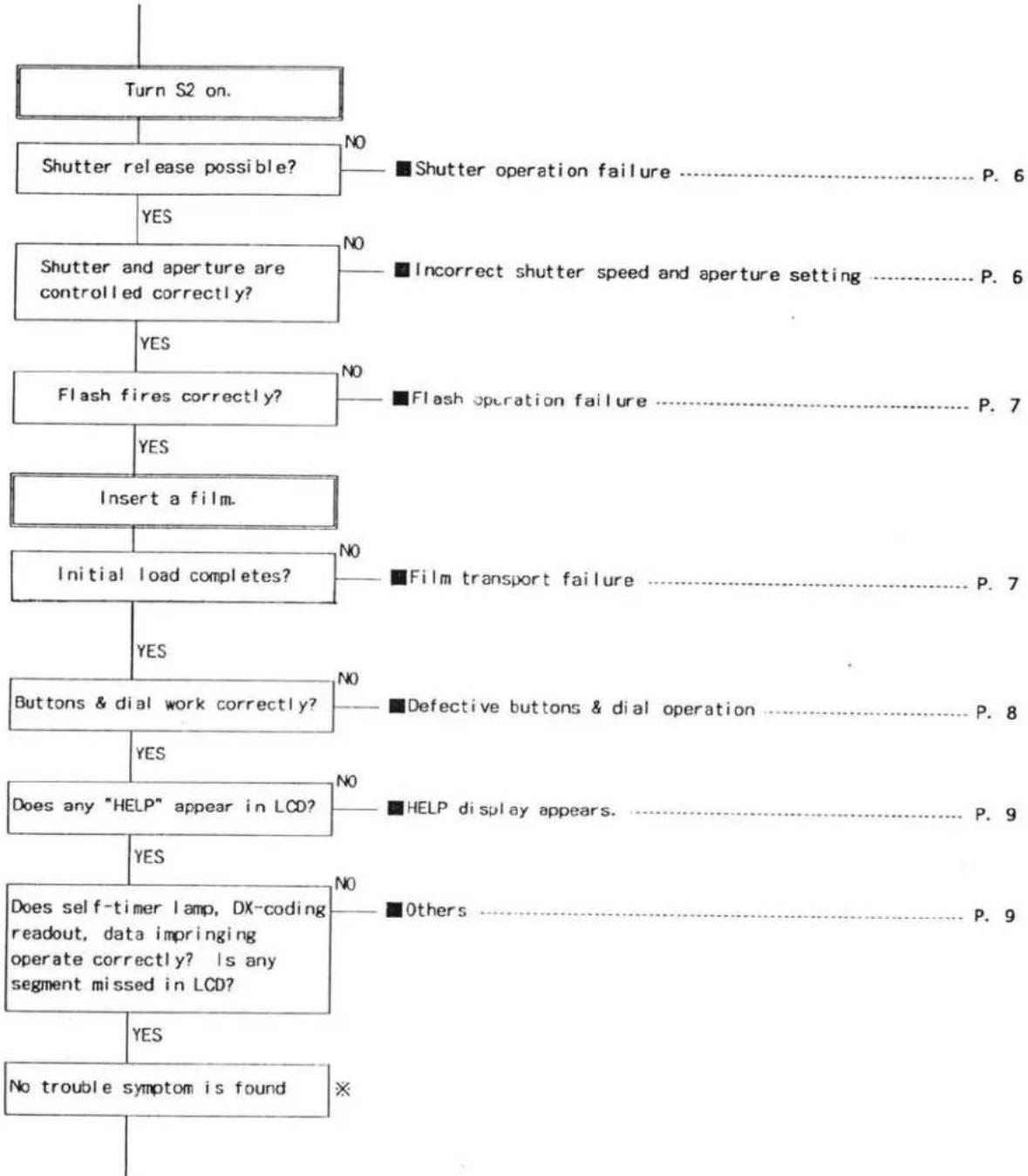
flowchart
graph TD
    A["Turn S2 on."] --> B["Shutter release possible?"]
    B -->|YES| C["Shutter and aperture are controlled correctly?"]
    B -->|NO| D["■Shutter operation failure P. 6"]
    C -->|YES| E["Flash fires correctly?"]
    C -->|NO| F["■Incorrect shutter speed and aperture setting P. 6"]
    C -->|NO| G["■Flash operation failure P. 7"]
    E -->|YES| H["Insert a film."]
    E -->|NO| I["■Film transport failure P. 7"]
    E -->|YES| J["Initial load completes?"]
    J --> K["Buttons & dial work correctly?"]
    J -->|NO| L["■Defective buttons & dial operation P. 8"]
    J -->|YES| M["Does any "HELP" appear in LCD?"]
    M --> N["Does self-timer lamp, DX-coding readout, data imprinting operate correctly? Is any segment missed in LCD?"]
    M -->|NO| O["■HELP display appears P. 9"]
    M -->|YES| P["Does not trouble symptom is found"]
    M -->|NO| Q["■Others P. 9"]
    M -->|YES| R["No trouble symptom is found"]
※If trouble symptom cannot be found with this chart,
- Using user's battery and lens, release the shutter about 100 times with a film loaded.
- With camera's lens mount side up or button side up, release the shutter to confirm the symptom pointed out by user.
Cause-finding chart
■No display in Data Panels. No camera activation
| Symptom | Cause | ||
| E. meat | Switch | Connector (CN) Lead wire | |
| Nothing appears in Body and Viewfinder Data Panels, and camera doesn't activate. | (FPC-A)C4、C6、C7、C9、C8、C18、R1、R2、X1X2 | SBATSM | Battery contacts (+)(- )CN-FC (2)(8)(9)(11) |
| Low battery symbol blinks, and camera doesn't activate. | (FPC-A)C3、C11、R3、R7、R25、Q3 | ||
■No initial loading operation (without film)
| Symptom | Cause | ||
| Element | Switch | Connector (CN)Lead wire | |
| Initial load operation doesn't start by battery installation(With main Sw. set to on, no film loaded) | W17 Winding motor (+)W18 Winding motor (-) | ||
■No reset to ∞ or specific position
| Symptom | Cause | ||
| Element | Switch | Connector (CN)Lead wire | |
| Lens ∞ reset or specific position reset doesn't operate when any lens is attached.Focus mode remains at M.POCUS.(AF doesn't operate.) | SLIK | CN BL (1)-(8)W10 (Gray)W11 (Black)Al motor (+)(-) | |
| Lens ∞ reset or specific position reset doesn't operate when an xi-lens is attached.Focus mode remains at M.POCUS.(AF doesn't operate.) | CN BL (3) | ||
■No stand-by display
| Symptom | Cause | ||
| Element | Switch | Connector (CN)Lead wire | |
| No display in Body Data Panel.(Others operate correctly) | (FPC-A)C12、C13、C14、C15、R21 | ||
| Shutter speed and aperturedisplay appear, and AF startsoperating. (Flash charge startsi f it is up.) | SI | ||
| Self-timer indicator appears.and camera doesn't operate. | SELF | ||
| Red-eye reduction indicatorappears, and camera doesn'toperate. | SPFL | ||
| Only "P" appears, and cameradoesn't operate. | SPCM | ||
| Film rewind starts, then "0"in frame counter with blinkingfilm cartridge mark appear. | SREW | ||
■No camera operation with stand-by display
| Symptom | Cause | ||
| Element | Switch | Detector (CN)Lead wire | |
| No camera activation with stand-by display on Body Data Panel. | S1 | (NHC L1) | |
| AF motor runs idle with stand-by display. | (FPC-A)C25 | ||
■Incorrect aperture and shutter speed display
| Symptom | Cause | ||
| Element | Switch | Connector (CN)Lead wire | |
| Aperture and shutter-speed displays flicker. | (HTC-A)G3.C4 | ||
■Incorrect displays in Viewfinder
| Symptom | Cause | ||
| Element | Switch | Connector (CN)Lead wire | |
| Back light of Viewfinder Data Panel doesn't light. | (PPC-A)R18 | CN-K (19) | |
■AF failure
| Symptom | Cause | ||
| Element | Switch | Connector (CN)Lead wire | |
| Lens moves in small steps. | (FPC-A)C22、C23、R17 | CN-G(1)(2)(3)CN-FC(7) | |
| Focus isn't confirmed. Lens keeps scanning for low-contrast. | (FPC-A)D2 | CN-B(1)(3)(7)(8) | |
■No power zoom or focus (with xi-series lens)
| Symptom | Cause | ||
| Element | Switch | Connector (CN)Lead wire | |
| Manual power zoom and power focus are impossible. | CN-BL(1) | ||
■Shutter operation failure
| Symptom | Cause | ||
| Element | Switch | Connector (CN)Lead wire | |
| Shutter release is impossible | S2 | W17 Winding motor (+)W18 Winding motor (-) | |
■Incorrect shutter speed or aperture setting
| Symptom | Cause | ||
| Element | Switch | Connector (CN)Lead wire | |
| No slit shutter | W4 (Blue)W6 (Yellow) | ||
| Incorrect shutter speed of 1/60 sec. or faster | W5 (Brown) | ||
| Aperture always set to fully-open position | (IPC-A)C24 | ||
■Flash operation failure
| Symptom | Cause | ||
| Element | Switch | Connector (CN)Lead wire | |
| Flash doesn't fire | W25 (Yellow)W28 (Orange)W29 (Blue)W30 (Yellow)W31 (Gray)W41W42CN-FC (6)(4) | ||
| Pre-flash fires, but main flash doesn't fire. | (EPC-A)R5 | W7 (Purple)W8 (Black) | |
| Flash output is less than required. | (EPC-A)R10 | ||
| Flash always fully fires. | (EPC-A)C19 | W1 | |
| Dedicated flash doesn't fire.(Others operate correctly.) | W21 (Purple)W24 (Black) | ||
| Dedicated flash doesn't fire.and camera doesn't operate. | W23 (Green) | ||
| Flash doesn't fire by manual fill-flash. | SFL | ||
| Flash charge doesn't start. | SFL10 | ||
■Film transport failure
| Symptom | Cause | ||
| Element | Switch | vector (CN)read wire | |
| Initial load doesn't start. | SRC | G | |
| Initial load always fails. | (N) (1) = (4) | ||
■Defective buttons & dial operation
| Symptom | Cause | ||
| Element | Switch | Connector (CN)Lead wire | |
| Focus Mode Button doesn't work. | SRAFSA-FM | CN-D (6)CN-M (6)W9 (Brown) | |
| Aperture Button doesn't work. | SAV | W19 (Orange)W20 (Black) | |
| Rewind Button doesn't work. | SREW | CN-D (4) (5) | |
| Display doesn't change according to Control Dial. | CN-DL (1)-(5) | ||
| Exposure Compensation Button doesn't work. | SOVR | CN-N (3) (4) | |
| Mode Button doesn't work. | SMODE | ||
| Drive-Mode/Self-Timer Button doesn't work. | SDRV | ||
| Flash-mode Button doesn't work. | SPRE | W14 (Brown)W16 (Blue) | |
| Program-Reset Button doesn't work. | STGM | W13 (Gray)W14 (Brown) | |
| Command Switch doesn't work. | SPT | W12 (Black)W15 (Green) | |
■HELP display appears.
| Symptom | Cause | ||
| Element | Switch | Connector (CN)Lead wire | |
| HELP appears at battery installation. | (FPC-A)R17、C26 | CN-PC (1)(5)(10)CN-O (1)-(9) | |
| HELP appears at lens reset. | CN-O (3) | ||
| HELP appears at SI on. | (FPC-A)C27、C29、R22、R23 | CN-PC (12)CN-B (2)(4)(5)(6)(9)(10) | |
| HELP appears after shutter release. | (FPC-A)C25、R4、R16、R19、R20 | SFP | CN-F (4)(6)(7) |
| After shutter release, mirror goes up and down several times, then HELP appears. | SLOAD | CN-M (1)(2)(3)CN-F (2)(3)(5) | |
| HELP appears at S2 on. | (FPC-A)R25 | ||
| Aperture is always set to stop-down position, and HELP appears. | (FPC-A)C10 | SFP | CN-F (4) |
Others
| Symptom | Cause | ||
| Element | Switch | Connector (CN)Lead wire | |
| Self-Timer Lamp doesn't light. | (FPC-A)R18 | ||
| Missing segments in Data Panels | (0-1)(1)-(26) | ||
| Mis-readout of DX-coding | (FPC-A)R11,R12 | (0-1)(7)-(11) | |
| No data imprinting | (0-1)(4)(5) | ||
| Data imprinting position doesn't change between panorama/normal. | (0-1)(1)(2) | ||
■Electrical elements on FPC-A
FPC-A
| Elements | Position |
| C2 | D-3 |
| C3 | D-3 |
| C4 | D-3 |
| C5 | D-3 |
| C6 | D-5 |
| C7 | C-5 |
| C8 | D-5 |
| C9 | D-5 |
| C10 | D-3 |
| C11 | C-4 |
| C12 | C-4 |
| C13 | C-4 |
| C14 | C-5 |
| C15 | C-4 |
| C18 | E-7 |
| C19 | E-7 |
| C22 | C-2 |
| C23 | D-8 |
| Elements | Position |
| C24 | D-7 |
| C25 | D-3 |
| C26 | D-2 |
| C27 | D-3 |
| C28 | C-3 |
| D1 | C-2 |
| D2 | D-3 |
| D3 | D-8 |
| X1 | D-5 |
| X2 | D-4 |
| Q1 | C-3 |
| Q2 | C-2 |
| Q3 | D-7 |
| Q4 | D-7 |
| R1 | D-4 |
| R2 | D-4 |
| R3 | C-3 |
| R4 | C-2 |
| Elements | Position |
| R5 | C-2 |
| R6 | B-3 |
| R7 | C-3 |
| R8 | C-3 |
| R9 | C-2 |
| R10 | E-7 |
| R12 | D-2 |
| R16 | D-7 |
| R17 | C-3 |
| R18 | E-6 |
| R19 | D-7 |
| R20 | D-5 |
| R21 | C-5 |
| R22 | D-2 |
| R22 | D-2 |
| R23 | D-2 |
| R24 | D-3 |
| R25 | D-7 |

text_image
FPC-A SET (ELECTRIC ELEMENT SIDE) A B C D E F 1 2 3 CN-B ① 108 ② GND ③ 167 ④ 170 ⑤ 168 ⑥ 123 ⑦ 117 ⑧ 109 ⑨ VCC2 ⑩ VCC1 Q 2 R 6 IC6 R12 R22 R23 R24 R25 R26 SPGM SPRE CN-G ① 479 ② GND ③ R17 コネクタ 例)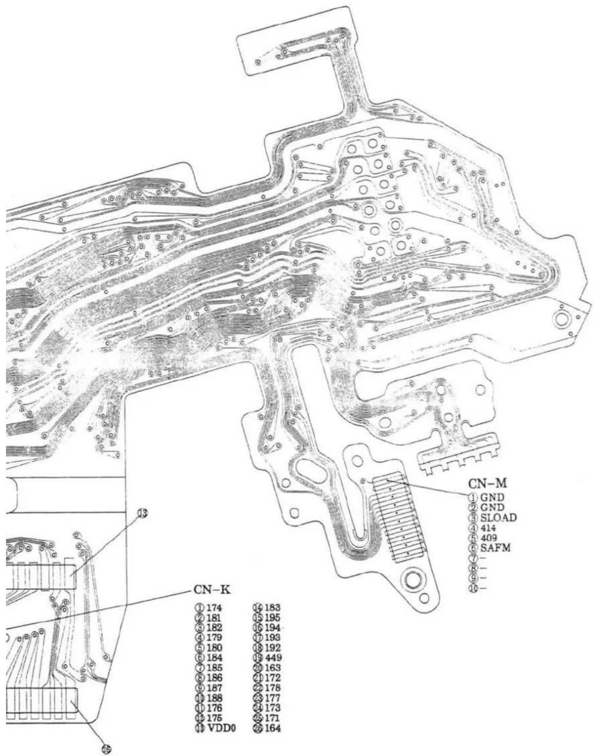
text_image
CN-K ① 174 16 183 ② 181 15 195 ③ 182 16 194 ④ 179 17 193 ⑤ 180 18 192 ⑥ 184 19 449 ⑦ 185 20 163 ⑧ 186 21 172 ⑨ 187 22 178 ⑩ 188 23 177 ⑪ 176 24 173 ⑫ 175 25 171 ⑬ VDD0 26 164 CN-M ① GND ② GND ③ SLOAD ④ 414 ⑤ 409 ⑥ SAFM ⑦ - ⑧ - ⑨ - ⑩ -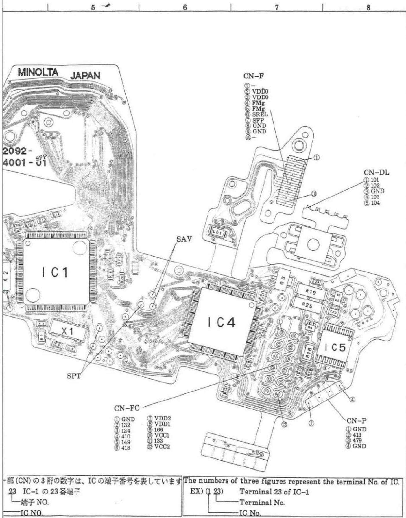
text_image
MINOLTA JAPAN 2092- 4001 - SFP X 2 IC1 X 1 SPT CN-F ①- ② VDD0 ③ VDD0 ④ FMg ⑤ FMg ⑥ SREL ⑦ SFP ⑧ GND ⑨ GND SAV IC4 R19 R25 IC5 R16 IC1 CN-DL ① 101 ② 102 ③ GND ④ 103 ⑤ 104 CN-P ① GND ② 413 ③ 479 ④ GND CN-FC ① GND ⑦ VDD2 ② 132 ⑧ VDD1 ③ 124 ⑨ 166 ④ 410 ⑩ VCC1 ⑤ 149 ⑪ 133 ⑥ 418 ⑫ VCC2 一部(CN)の3桁の数字は、ICの端子番号を表しています 23 IC-1 の23番端子 端子NO. IC NO. The numbers of three figures represent the terminal No. of IC. EX) (1 23) Terminal 23 of IC-1 Terminal No. IC No.12 (2092)
FPC-A SET
NO COMPONENT SIDE

text_image
CN-D ① SPANO ② GND ③ SRC ④ SREW ⑤ 125 ⑥ SRAF ⑦ R11-466 CAS2 ⑧ R12-467 CAS3 ⑨ R12-468 CAS4 ⑩ R12-464 CAS5 ⑪ R12-465 CAS6 CN-O ① 118 ② 169 ③ 131 ④ 107 ⑤ VDD1 ⑥ VCC1 ⑦ GND ⑧ GND ⑨ C2 SM 10m CN-BL ① GND ② VDD0 ③ 406 ④ GND ⑤ R6-116 ⑥ R6-408 ⑦ VDD1 ⑧ R6-407 CN-N ① GND ② SFL ③ 146 ④ 125 SLLKFLASH CONVERTER PCB SET
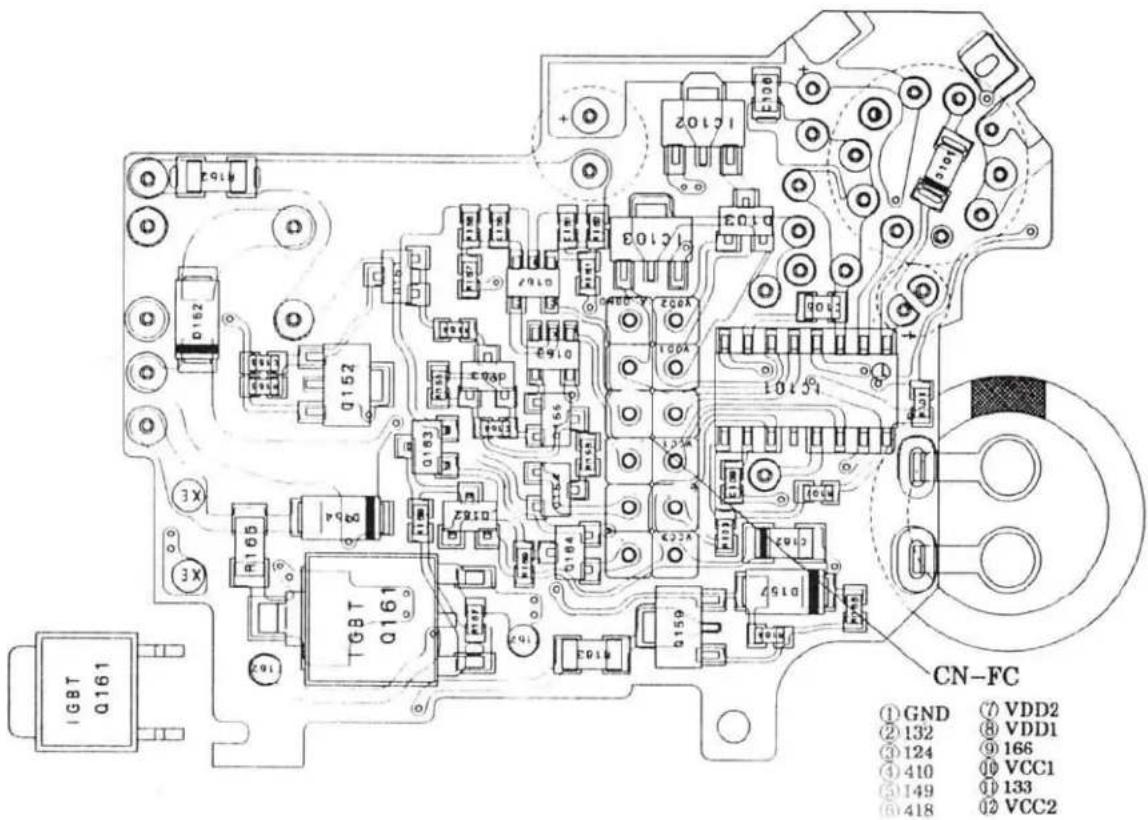
text_image
IGBT Q161 TGBT Q161 CN-FC ① GND ⑦ VDD2 ② 132 ⑧ VDD1 ③ 124 ⑨ 166 ④ 410 ⑩ VCC1 ⑤ 149 ⑪ 133 ⑥ 418 ⑫ VCC2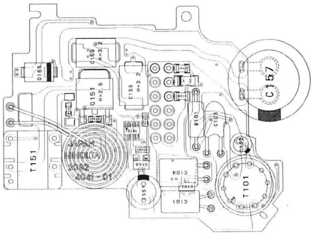
text_image
T151 Q151 H=2.5 C159 H=3.2 C158 H=3.2 JAPAN MINDITA 2082 10-100V C156 C104 C101 C103 C157 T101Check List
- This CHECK LIST describes the quality of operation warranted to general users. When users inquire about quality or request inspection, refer to this CHECK LIST.
Use this list also when checking operation after repair.
-
When using this list during shipping or receiving inspection, judge the quality according to purpose of the inspection, not by directly referring to this level.
-
For individual taste or special usage, some users may not be satisfied with this level of quality and will request a different one.
In such cases, adjust the level as requested by them as much as possible.
- Unless otherwise mentioned, use standard lens (2550-100) or master lens (2072-0001-75) for the following inspections.
Initial setting
At battery installation
- By installing a battery with Main Switch turned on, camera is reset as follows:
Exposure mode: P
Exposure compensation:±0
Drive-mode: single
Focus mode: auto-focus
Battery condition indicator: appears and remains for 3 sec.
- By installing a battery with Main Switch turned on, lens is reset as follows:
AF lens: set to a specific focus position after ∞ reset.
xi-series lens: set to a specific focus position after zoom wide-end reset.
At Main Switch slid to ON
- By sliding Main Switch to on, the last setting before Main Switch was turned off is displayed in Body Data Panel.
- Battery condition indicator appears and disappears 3 sec. after.

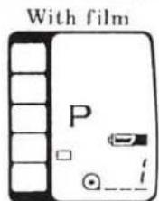
- By sliding Main Switch to on, lens is reset as follows:
AF lens: set to a specific focus position after reset.
xi-series lens: set to a specific focus position after zoom wide-end reset.
At main Switch slid to OFF
- By sliding Main Switch to off, all displays in Body Data Panel disappear.

- By sliding Main Switch to off, lens is set as follows:
AF lens: retracts to its ∞ end.
xi-series lens: retracts to its shortest position.
Settings & Displays
| Exposure mode selection | ·Turning Control Dial while pressing and holding Mode Button will change displays as follows: ·Command Switch is set to exposure mode selection "A"M": P←→A←→S←→M ·Command Switch is set to subject program selection "": |
| Program reset | ·By pressing Program-Reset Button, displays in data panels restore to initial settings as follows: Exposure mode: P Exposure compensation:±0 Drive-mode: Single Focus mode: Auto Wireless flash: canceled Self-timer: canceled |
| Drive-mode | ·While pressing and holding Drive-mode/Self-timer Button, turning Control Dial will change displays as follows: |
| Single-drive←→Self-timer←→Continuous-drive | |
| Exposure compensation | ·While pressing and holding Exposure-Compensation Button, turning Control Dial will set the compensation value in 1/2-stop increments from □3.0EV to □3.0 EV. |
| Flash mode | ·By each press of Flash-Mode Button, Red Eye Reduction Indicator appears and disappears alternately. Normal flash←→Red-Eye-Reduction flash "◎" ·When a dedicated flash unit is attached, by pressing the Flash-Mode Button, "WL" appears in Body Data Panel and the camera is set to wireless flash mode. |
| Focus mode | ·Pressing Focus Mode Button changes focus mode to auto focus or manual focus. At manual focus: Display as "M.FOCUS" appears in Body Data Panel. At auto focus: The "M.FOCUS" disappears. Lens is reset to ∞ then to a specific position, or reset to wide-end then to a specific position (xi-series lens) |
Operation
| P mode | Shutter speed and aperture settings are automatically set.If required exposure settings are beyond camera's control range, " [ ] and shutter speed display blink. |
| A mode | Turning Control Dial changes aperture display in both Body and Viewfinder Data Panels in 1/2-stop increments.Shutter speed is automatically set.If required exposure settings are beyond camera's control range, shutter speed display blinks in both Body and Viewfinder Data Panels. |
| S mode | Turning Control Dial changes shutter speed display in both Body and Viewfinder Data Panels in 1/2-stop increments.Aperture is automatically set.If required exposure settings are beyond camera's control range, aperture display blinks in both Body and Viewfinder Data Panels. |
| M mode | Turning Control Dial changes shutter speed display in both Body and Viewfinder Data Panels.Turning Control Dial while pressing and holding Aperture Button changes aperture display in both Body and Viewfinder Data Panels.One of the following Exposure-Adjustment Indicator appears in Viewfinder Data Panel.Over exposure: [+]Optimum exposure:Under exposure: [−] |
Single-drive | While pressing and holding Shutter-Release Button, shutter runs only for one time. |
Continuous drive | In manual focus mode, while pressing and holding Shutter-Release Button, shutter runs continuously (1 frm/sec).In AF mode, while pressing and holding Shutter-Release Button, shutter runs continuously, but only after focus is confirmed. |
Self-timer | By pressing Shutter-Release Button after Self-timer mode is set, Self-timer Indicator and Self-timer Lamp start blinking in 2Hz.Shutter is released 10 sec. after. |
4 (2092)
Auto focus
- By pressing Shutter-Release Button partway down (S1 on), AF system starts operating and one of the following focus signals appears in Viewfinder Data Panel.

light: Focus is confirmed in continuous AF mode.
light: Focus cannot be confirmed.
blinking: Focus cannot be confirmed (low contrast)

light: Focus and exposure are locked.
- AF illuminator;
With built-in flash lifted and AF illuminator is set, the built-in flash fires in low-light and low-contrast to aid focus.
※Sliding Main Switch to on while pressing and holding
Flash-Mode Button sets or cancels AF illuminator, and one of the following displays appears in Body Data Panel until you release the button.
AF illuminator c. led: "oFF AF"
AF illuminator set: "un AL"
Manual focus
- By pressing Shutter-Release Button partway down, one of the following focus signals appears in Viewfinder Data Panel.
● light: Focus is confirmed.
Nothing appears: Focus cannot be confirmed.
- blinking: Focus cannot be confirmed (low-contrast).
• AF illuminator doesn't light.
Normal & Red-Eye-Reduction mode (With flash raised or dedicated flash attached and turned on)
- When flash charge is completed, " 2" appears in Viewfinder Data Panel.
- When flash is fired and controlled correctly, " 1" blinks by 2Hz.
- In P mode, flash automatically fires if necessary. And flash always fires by a Shutter-Release while pressing and holding Flash-Control Button.
• In A, S, and M mode, flash always fires.
Wireless flash mode
- In wireless flash mode, pressing Flash-Mode Button will make a test firing.
| Normal,Red-Eye-Reduction mode | Wireless flash mode | |||
| Exposure mode | Shutter speed | Aperture | Shutter speed | Aperture |
| P | Automatically set | |||
| A | 1/90 or 1'60 | Manually set | 1/45 | Manually set |
| S | Automatically set | |||
| M | Set to 1/90 or slower | Manually set | Set to 1/45 or slower | Manually set |


Film transport
| Initial load | ·When initial load is completed, " ⊙_! " appears in Body Data Panel.·When initial load is failed, " ⊙_∅ " appears and " [IMAGE] " blinks in Body Data Panel. |
| Rewind | ·During film rewind, number in Frame Counter decreases accordingly.·When film rewind is completed, " ⊙ 3 " appears and " _∅ " blinks in Body Data Panel.·After film rewind, tip of film is stored in film cartridge. |
| Film transport time | ·From rewind start to completion: approx. 17 sec.(Film: KODAK Gold 100, 24Exp., Voltage: 5.8V ;Using power supply adapter) |
Standards
Manual shutter speed · Use Shutter Tester MODEL S-2201 or S-2101.
| Shutter speed | Standard (ms) | Allowable range(ms) | Difference | Uneven exposure |
| 1/2000 | 0.488 | 0.311-0.766 | ±0.65EV | Difference between max. and min. of three values (Range -A, -B, -C); within±0.6EVDifference between range -A & -B, range -B & -C; ±0.3EV |
| 1/1000 | 0.977 | 0.667-1.430 | ±0.55EV | |
| 1/500 | 1.95 | 1.58-2.40 | ±0.3EV | |
| 1/250 | 3.91 | 3.18-4.81 | ||
| 1/125 | 7.81 | 6.34-9.62 | ||
| 1/90 | 11.1 | 9.02-13.7 | ||
| 1/60 | 15.6 | 12.7-19.2 | ||
| 1/30 | 31.3 | 29.2-33.5 | ±0.1EV | |
| 1/15 | 62.5 | 58.3-67.0 | ||
| 1/8 | 125 | 117-134 | ||
| 1/4 | 250 | 233-268 | ||
| 1/2 | 500 | 467-536 |
X-sync. delay time
| Shutter speed | Measured item | Allowable range |
| 1/90 | X-contact delay time | 0.4 to 0.9ms |
| From X-contact on to 2nd curtain appearance | 2.4ms or more |
AE level
Use standard lens (2550–100/50mm,f/1.7), ISO100 film, and EE tester (K value 1.3)
| Exposure mode | Luminance | Shutter speed | Aperture | Allowable range |
| P | EV15 | - | - | within 0±1.0EV |
| EV12 | ||||
| EV10 | ||||
| EV6 | ||||
| EV4 | ||||
| A | EV15 | - | F5.6 | |
| EV10 | F1.7 | |||
| EV10 | F5.6 | |||
| EV10 | F22 | |||
| EV6 | F5.6 | |||
| S | EV15 | 1/1000 | - | |
| EV10 | 1/250 | |||
| EV10 | 1/30 | |||
| EV10 | 1/8 | |||
| EV6 | 1 |
Flash level
- Check flash level with ISO100 film.
Standard: F5.6±0.5EV
※ See P. 25 of Repair Guide.
Current leak
| Item | Allowable range |
| During Main Switch of: | 50μA or less |
| During Main Switch on | 50μA or less |
Current consumption
- Use 5.8V, 2CR5-type power supply adapter.
| Item | Allowable range |
| At Shutter-Release | 80mA or less |
| At film advance | 700mA or less |
| At film rewind | 700mA or less |
B.C. lock voltage
- Use 2CR5 type power _1,2 by adapter for B.C. adjustment. B.C. lock operates at 4.75V or below.
Body back
• Standard: 44.710±0.015mm