
EY79A2 - Power Tools PANASONIC - Free user manual and instructions
Find the device manual for free EY79A2 PANASONIC in PDF.

| Tool type | Cordless hammer drill driver |
| Brand | Panasonic |
| Model | EY79A2 |
| Nominal voltage | 14.4 V DC / 18 V DC (depending on version) |
| Battery type | Lithium-ion (recommended: Panasonic) |
| Chuck capacity | 1.5 mm – 13 mm (keyless) |
| No-load speed (low/high) | 30-400 / 70-1350 min⁻¹ (14.4 V); 30-470 / 70-1580 min⁻¹ (18 V) |
| Torque (clutch) | 1.0 – 4.4 N·m (18 positions + drill/hammer) |
| Hammer mode | Yes (for soft concrete) |
| Total length | 188 mm |
| Weight (with battery) | Approximately 1.70 kg – 2.10 kg depending on battery |
| LED light | Yes, 3 modes (constant, trigger, off) |
| Battery charge indicator | Yes, 3 levels (full, ~60%, low) |
| Overload/overheat protection | Yes (automatic stop with indicator) |
| Motor brake | Yes (quick stop of rotation) |
| Belt hook | Removable and reversible (both sides) |
| Maintenance | Clean with a dry, clean cloth; do not use water or solvent |
| Included accessories | Battery, charger, belt hook (depending on version) |
| Warranty | Refer to manual; heavy wear not covered |
| Intended use | Screwing, drilling in wood and metal, hammer drilling (soft concrete) |
Frequently Asked Questions - EY79A2 PANASONIC
User questions about EY79A2 PANASONIC
0 question about this device. Answer the ones you know or ask your own.
Ask a new question about this device
Download the instructions for your Power Tools in PDF format for free! Find your manual EY79A2 - PANASONIC and take your electronic device back in hand. On this page are published all the documents necessary for the use of your device. EY79A2 by PANASONIC.
USER MANUAL EY79A2 PANASONIC
natural_image
Line drawing of a handheld electric drill press with attached battery (no text or symbols)Pictured: EY74A2
Before operating this unit, please read these instructions completely and save this manual for future use.
NOTE: Not all battery packs display the alignment mark (Q).
[Fig.2]
[Fig.3]
[Fig.4]
[Fig.5]

Forward
Rechts
Rotation en sens normal
Avanti
Rechts
Avance
Forlæns
Framåt
Forover
Eteenpäin
İleri
Prawo
Dopředu
Jobbra
natural_image
Two identical mechanical components with concentric circular features and a base mount (no text or symbols)
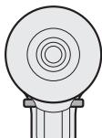
Switch lock
Schaltersperre
Verrouillage du
commutateur
Blocco interruttore
Vergrendelstand
Bloqueo delinterruptor
Omskifterlås
Låst läge
Bryterlås
Kytkinlukko
Anahtar kilidi
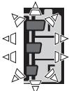
natural_image
Technical line drawing of a mechanical component with no visible text or symbols
HIGH
HOCH
HAUT
ALTO
HOOG
ALTA
H∅J
HÖGA VARVTAL
H∅Y
SUURI
YÜKSEK
HIGH
VYSOKÝ
MAGAS
[Fig.8]
natural_image
Technical illustration of a mechanical device with exploded view and directional arrows indicating assembly (no text or symbols)[Fig.9]
Pack cover
Akkuabdeckung
Couvercle de la
batterie autonome
Coperchio pacco
Accudeksel
Cubierta de batería
Pakningsdæksel
Batteriskydd
Pakkedeksel
Akkukotelon kansi
Pil takımı kapağı
Osłona akumulatora
Kryt bloku
natural_image
Diagram of a device with an open lid and internal components, no text or symbols presentLabel (red or yellow)
Label (rood of geel)
Etiqueta (roja o amarilla)
Battery pack release button
natural_image
Illustration of a printer with an attached device and paper feed, showing no text or symbols.Alignment marks
Original instructions: English Translation of the original instructions: Other languages
Read “the Safety Instructions” booklet and the following before using.
I. INTENDED USE
These tools can be used to tighten screws in clutch mode and to drill holes in wood and metal in drill mode. Additionally, model EY79A2 can be used to drill holes in soft concrete and similar materials in hammer mode.
II. ADDITIONAL SAFETY RULES
1) If the bit becomes jammed, immediately turn the trigger switch off to prevent an overload, which can damage the battery pack or motor. Use reverse motion to loosen jammed bits.
2) Do NOT operate Forward/Reverse lever when the trigger switch is on. The battery will discharge rapidly and damage to the main unit may occur.
3) During charging, the charger may become slightly warm. This is normal. Do NOT charge the battery for a long period.
4) Do not strain the tool by holding the speed control trigger halfway (speed control mode) so that the motor stops.
5) To prevent injury during use, hold the tool steady at all times and avoid waving it around.
6) Ensure that there are no hidden gas or water pipes in the area in which you will be working. Contact with hidden pipes or wires could cause electric shock or water or gas leaks.
7) Make sure to hold the object you are working on steady.
8) Check for damaged parts.
- Check thoroughly for damage to the protective cover and other parts before operating.
- Check to make sure the tool and all of its functions are working properly.
- Check the adjustment of all movable parts, and check all fixed parts to make sure they are fitted properly and free of damage. Check all parts of the tool for abnormal function.
9) When attempting to repair the protective cover or other parts, please follow the instructions in the user manual. In cases where there are no instructions in the manual, please take it back to the store to have it repaired.
10) If the tool gets exceptionally hot during use, please take it in for service and repair.
11) To avoid potential injury, keep face and hands away from the drill bit and any shavings.
12) Do not wear gloves when operating the tool, as they may get caught by the drill, leading to injury.
13) Battery terminals, screw shavings, and tool accessories such as drill bits will be very hot immediately after operation. Do not touch them as there is a risk of burning yourself.
| Symbol | Meaning |
| V | Volts |
| --- | Direct current |
| n_0 | No load speed |
| ... min ^-1 | Revolutions or reciprocations per minutes |
| Ah | Electrical capacity of battery pack |
| Rotation only | |
| T(EY79A2 only) | Rotation with hammering |
| Read the operating instructions before use. | |
| For indoor use only. |
EN

WARNING
- Do not use other than the Panasonic battery packs that are designed for use with this rechargeable tool.
- Panasonic is not responsible for any damage or accident caused by the use of recycled or counterfeit battery pack.
- Do not dispose of the battery pack in a fire, or expose it to excessive heat.
- Do not allow metal objects to touch the battery pack terminals.
- Do not carry or store the battery pack in the same container as nails or similar metal objects.
- Do not charge the battery pack in a high-temperature location, such as next to a fire or in direct sunlight. Otherwise, the battery may overheat, catch fire, or explode.
• After removing the battery pack from the tool or the charger, always reattach the pack cover. Otherwise, the battery contacts could be shorted, leading to a risk of fire. - When the Battery Pack Has Deteriorated, Replace It with a New One. Continued use of a damaged battery pack may result in heat generation, ignition or battery rupture.
- To prevent leakage, overheating, smoke generation, fire, and rupturing from occurring, follow these instructions when handling our rechargeable power tools (tool main body/battery pack/charger).
- Do not allow material cuttings or dust to fall onto the battery pack.
- Before storing, remove any material cuttings and dust from the battery pack, fit red plastic “terminal cover”, then place separately from metal objects (screws, nails, etc.) in tool case. Damage caused by loose objects in the case will not be covered by warranty.
- Do not handle the rechargeable power tools in the following way. (There is a hazard of smoke generation, fire, and rupturing)
- Use or leave in places exposed to rain or moisture
- Use submerging in water
III. ASSEMBLY
Attaching or Removing Bit
NOTE:
When attaching or removing a bit, disconnect battery pack from the main unit or place the switch in the center position (switch lock).
The main unit is equipped with a keyless drill chuck.
- Attachment Insert the bit and turn the lock collar clockwise (looking from the front) to tighten firmly until it stops clicking. [Fig.1]
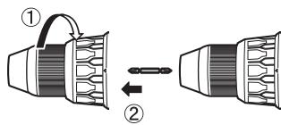
- Removal Turn the lock collar counterclockwise (looking from the front), then remove the bit. [Fig.2]
NOTE:
If there is excessive play in the chuck, secure the drill in place and open the chuck jaws by turning the lock collar and tighten the screw (left-handed screw) with a screwdriver by turning it counterclockwise (viewed from the front). [Fig.3]
Attaching or Removing Battery Pack
NOTE:
When the battery pack is removed from the main unit, the control panel lamp may light up briefly. This is not a malfunction.
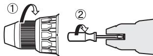
- To attach the battery pack: [Fig.4] Align the highlighted marker points and attach battery pack. Slide the battery pack until it locks into position.
- To remove the battery pack: [Fig.4] Push the button and slide the battery pack forward.
IV. OPERATION

WARNING!
- Do not inhale smoke emitted from the main unit or battery pack as it may be harmful.
[Main Unit]
CAUTION
When storing or carrying the tool, set the Forward/Reverse lever to the center position (switch lock).
NOTE:
Exercise caution to ensure no objects come into contact with the tool's trigger switch.
If an object comes into contact with the tool's trigger switch, even while the Forward/Reverse lever is in the center position (locked), a small amount of electric current may continue flowing, which may cause an excessive discharge from the battery pack and subsequent battery pack failure.
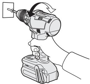
Switch and Forward/Reverse Lever Operation [Fig.5]
- Push the lever for forward or reverse rotation. Check the direction of the lever before using.
- Depress the trigger switch slightly to start the tool slowly.
- Speed will increase by pressing the trigger. The tool stops working immediately by releasing the trigger.
- When done with an application, lock the switch by centering the lever.
NOTE:
When the brake operates, a braking sound may be heard. This is normal.
CAUTION:
When operating the tool by pulling the trigger, there may be a momentary lag before rotation starts. This does not signal a malfunction.
* This lag occurs as the tool's circuitry starts up when the trigger is pulled for the first time after installing a battery pack or after the tool has not been used for at least 1 minute (or at least 5 minutes when the LED is on). Rotation will start without any lag during second and subsequent operations.
CAUTION:
To prevent damage, do not operate Forward/Reverse lever until the bit comes to a complete stop.
Clutch Torque Setting
Adjust the torque to one of the 18 clutch settings or “♂”, “T (EY79A2 only)” position.
CAUTION:
- Set the clutch setting at this mark [Fig.6] before actual operation.
- If the clutch handle cannot be set at "drilling" mode after driving with clutch function, set the clutch handle at position 1 and operate the clutch for a second.
Speed Selection
Choose a low or high speed to suit the use. [Fig.7]
The more the variable speed control trigger is pulled, the higher the speed becomes.
CAUTION:
- Check the speed selector switch before use.
- Use in low gear when high torque is required in operation. (Using in high gear with high load can cause motor overload and possible failure.)
- To prevent excessive temperature increase of the tool surface, do not operate the tool continuously using two or more battery packs. The tool needs cool-off time before switching to another pack.
- Ensure that air vents on the sides of the main unit are not blocked during operation. Covering them can cause the tool to overheat and motor damage to occur.
- Do NOT strain the tool (motor). This may cause damage to the tool.
- Avoid contact with air from vent holes during operation as under heavy load this can become hot and potentially cause injury.
EN
Speed Control Function
Setting the maximum speed.
-
Press the speed setting button and select a speed.
The speed changes to H, M, L and OFF (the light is off) in this order. -
Select OFF to release it.
| Display | Low mode | High mode |
| H | Approx. 300 min ^-1 (rpm) | Approx. 1000 min ^-1 (rpm) |
| M | Approx. 200 min ^-1 (rpm) | Approx. 670 min ^-1 (rpm) |
| L | Approx. 150 min ^-1 (rpm) | Approx. 500 min ^-1 (rpm) |
| OFF | Ordinary speed18 V Approx. 470 min ^-1 (rpm)14.4 V Approx. 400 min ^-1 (rpm) | Ordinary speed18 V Approx. 1580 min ^-1 (rpm)14.4 V Approx. 1350 min ^-1 (rpm) |
- Default setting: OFF
- The speed is the same using either 14.4 V or 18 V when H, M, L settings are selected.
- If a high mode is chosen, the speed is set as the table above.
3 Mode LED Light
Press the light button to select illumination setting.
Illuminated - Constant
Select by pressing lamp button light will activate when trigger is pressed. It will then stay illuminated for approximately 5 minutes even if tool is not used but will then switch off automatically to save power.
Illuminated - On trigger
By pressing the lamp button again, the mode will move to illumination upon the pressing of the trigger only. Will switch off when trigger is released.
Off
The light illuminates with very low current, and it does not adversely affect the performance or its battery capacity.

CAUTION:
- The built-in LED light is designed to illuminate the small work area temporarily.
- Do not use it as a substitute for a regular flashlight, since it does not have enough brightness.
CAUTION: DO NOT STARE INTO BEAM.
Use of controls or adjustments or performance of procedures other than those specified herein may result in hazardous radiation exposure.
Battery Level Indicator
Press the battery level button. Battery level indicator shows battery level in three levels while pressing the button.
NOTE:
The indicator will not show the battery level when the button is pressed in the following cases.
- The tool is powered off.
- Just after attaching the battery pack
- The main unit or battery level button is not operated for approx. five minutes. Press the battery level button again after depressing the trigger switch.
- If the battery temperature is high, stop the operation and wait until the battery temperature is low.
| Indicator | Battery status | |
 | 3 lamps illuminated | Fully charged or high charge level |
 | 2 lamps illuminated | Approx. 60% remaining |
 | One lamp illuminated | Low level- Will require charging soon |
 | 3 lamps flashing | Empty- Immediate charging required |
This battery level function is only a guide and indication may change due to the condition of the battery or ambient temperature.
Excessive (complete) discharging of lithium ion batteries shortens their service life dramatically. The driver includes a battery protection feature designed to prevent excessive discharging of the battery pack.
Bit-locking Function
EN
- With the trigger switch not depressed and a screwdriver bit locked in place, the tool can be used as a manual screwdriver (up to 22.6 N·m, 230 kgf·cm, 199 in·lbs).
There will be a little play in the chuck, but this is not a malfunction. - This feature is handy for tightening screws that require more torque than the maximum torque of the driver (position on the clutch), for confirming the tightness of a screw or to loosen an extremely tight screw.
natural_image
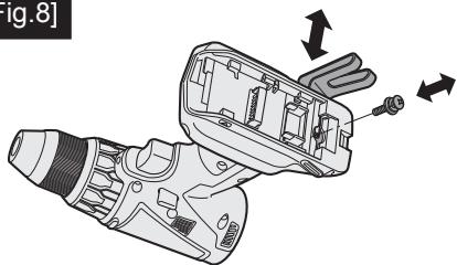
Line drawing of a hand using a power tool to lift a cylindrical device (no text or symbols present)Changing the Belt Hook Location Side [Fig.8]
The belt hook can be attached to either side of the unit.
- Removing the hook
(1) Remove the nut.
(2) Draw out the hook.
- Attaching the hook to the other side
(1) Insert the hook in the other side.
(2) Tighten the nut fully so that it securely fastened.
EN

WARNING!
- Be sure to attach the belt hook securely to the main unit with the screw firmly fastened. When the belt hook is not firmly attached to the main unit, the hook may disconnect and the tool may fall. This may result in an accident or injury.
- Periodically check screw for tightness. If found to be loose, tighten firmly.
- Be sure to attach the belt hook firmly and securely onto a waist belt or other belt. Pay attention that the tool does not slip off the belt. This may result in an accident or injury.
- When the tool is held by the belt hook, avoid jumping or running with it. Doing so may cause the hook to slip and the tool may fall. This may result in an accident or injury.
- When the tool is hooked onto the waist belt by the belt hook, do not attach driver bits to the tool. A sharp edge object, such as a drill bit, may cause injury or an accident.
Warning Functions
(1) Overheat Warning


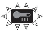
Off (normal operation)
Illuminated: Overheat (motor)
Flashing: Overheat (battery)
Indicates operation has been halted due to motor or battery overheating.
To protect the motor or battery, be sure to note the following when carrying out this operation.
- If the motor or battery becomes hot, the protection function will be activated and the motor or battery will stop operating. The overheat warning lamp on the control panel illuminates or flashes when this feature is active.
- If the overheating protection feature activates, allow the tool to cool thoroughly (at least 30 minutes). The tool is ready for use when the overheat warning lamp goes out.
- Avoid using the tool in a way that causes the overheating protection feature to activate repeatedly.
- If the tool is operated continuously under high-load conditions or if it is used in hot-temperature conditions (such as during summer), the overheating protection feature may activate frequently.
- If the tool is used in cold-temperature conditions (such as during winter) or if it is frequently stopped during use, the overheating protection feature may not activate.
The performance of the EY9L42 deteriorates significantly at and below 10^ C due to work conditions and other factors.
(2) Voltage Reduction Warning

One lamp flashing
If the tool is subject to a sudden load during use that causes the motor to lock up, the overdischarge prevention sensor may be triggered, and the battery low warning lamp may flash. The lamp will stop flashing once you address the cause of the motor's locking up and cycle the trigger.
(3) Overload Warning

If the tool is subject to a sudden load during use that causes the motor to lock up, the overcurrent prevention sensor may be triggered, the voltage reduction warning lamp may illuminate and flash. (Bottom of it illuminates and middle and top flashes.)
The lamp will stop illuminating and flashing once you address the cause of the motor's locking up and cycle the trigger.
[Battery Pack]
For Appropriate Use of Battery Pack [Fig.9]
- The rechargeable batteries have a limited life.
- For optimum battery life, store the Li-ion battery pack following use without charging it.
- When operating the battery pack, make sure the work place is well ventilated.
For safe use
- The battery pack is designed to be installed by proceeding two steps for safety. Make sure the battery pack is installed properly to the main unit before use.
- If the battery pack is not connected firmly when the switch is switched on, the overheat warning lamp and the battery low warning lamp will flash to indicate that safe operation is not possible, and the main unit will not rotate normally. Connect the battery pack into the unit of the tool until the red or yellow label disappears.
[Battery Charger]
Charging
CAUTION:
1) If the temperature of the battery pack falls approximately below -10^ ( 14^ ), charging will automatically stop to prevent degradation of the battery.
2) The ambient temperature range is between 0^ C ( 32^ F) and 40^ C ( 104^ F).
If the battery pack is used when the battery temperature is below 0^ C ( 32^ F), the tool may fail to function properly.
3) Use the charger at temperatures between 0^ C and 40^ C, and charge the battery at a temperature similar to that of the battery itself. (There should be no more than a 15^ C difference between the temperatures of the battery and the charging location.)
4) When charging a cool battery pack (below 0^ C ( 32^ F)) in a warm place, leave the battery pack at the place and wait for more than one hour to warm up the battery to the level of the ambient temperature.
5) Cool down the charger when charging more than two battery packs consecutively.
6) Do not insert your fingers into contact hole, when holding charger or any other occasions.
7) Unplug the charger when not in use.
NOTE:
Your battery pack is not fully charged at the time of purchase. Be sure to charge the battery before use.
How to charge
NOTE:
- Plug the charger into the AC outlet.
Sparks may be produced when the plug is inserted into the AC power supply, but this is not a problem in terms of safety. - Connect the battery pack firmly into the charger.
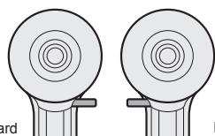
1 Line up the alignment marks and place the battery onto the dock on the charger.
NOTE:
Not all battery packs display the alignment mark (Q) (on page 2).
2 Slide forward in the direction of the arrow. [Fig.10]
-
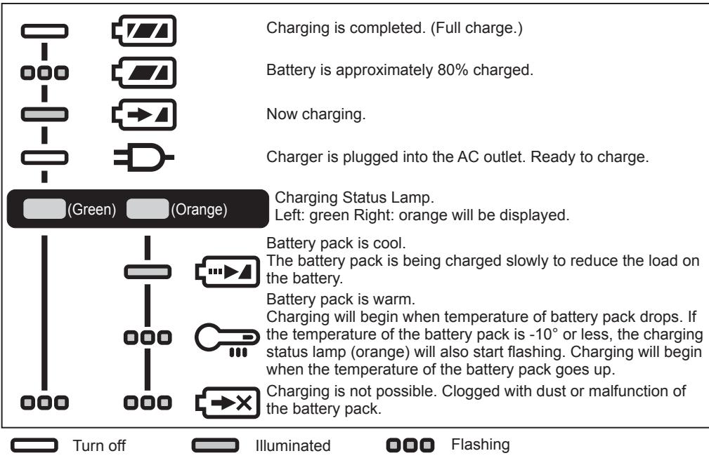
During charging, the charging lamp will be lit. When charging is completed, an internal electronic switch will automatically be triggered to prevent overcharging.
-
Charging will not start if the battery pack is hot (for example, immediately after heavy-duty operation). The orange standby lamp will be flashing until the battery cools down. Charging will then begin automatically.
- The charge lamp (green) will flash slowly once the battery is approximately 80% charged.
EN
- When charging is completed, the charging lamp in green color will turn off.
-
If the temperature of the battery pack is 0^ C or less, charging takes longer to fully charge the battery pack than the standard charging time.
Even when the battery is fully charged, it will have approximately 50% of the power of a fully charged battery at normal operating temperature. -
Consult an authorized dealer if the charging lamp (green) does not turn off.
-
If a fully charged battery pack is inserted into the charger again, the charging lamp lights up. After several minutes, the charging lamp in green color will turn off.
-
Remove the battery pack while the battery pack release button is held up. [Fig.10]
LAMP INDICATIONS
Battery Recycling
ATTENTION:
For environmental protection and recycling of materials, be sure that it is disposed of at an officially assigned location, if there is one in your country.
Information for Users on Collection and Disposal of Old Equipment and used Batteries
EN

These symbols on the products, packaging, and/or accompanying documents mean that used electrical and electronic products and batteries should not be mixed with general household waste.
For proper treatment, recovery and recycling of old products and used batteries, please take them to applicable collection points, in accordance with your national legislation and the Directives 2012/19/EC and 2006/66/EC.

By disposing of these products and batteries correctly, you will help to save valuable resources and prevent any potential negative effects on human health and the environment which could otherwise arise from inappropriate waste handling.
For more information about collection and recycling of old products and batteries, please contact your local municipality, your waste disposal service or the point of sale where you purchased the items.
Penalties may be applicable for incorrect disposal of this waste, in accordance with national legislation.
[For business users in the European Union]
If you wish to discard electrical and electronic equipment, please contact your dealer or supplier for further information.
[Information on Disposal in other Countries outside the European Union]
These symbols are only valid in the European Union. If you wish to discard these items, please contact your local authorities or dealer and ask for the correct method of disposal.
V. MAINTENANCE
- Use only a dry, soft cloth for wiping the unit.
Do not use a damp cloth, thinner, benzine, or other volatile solvents for cleaning.
- In the event that the inside of the tool or battery pack is exposed to water, drain and allow to dry as soon as possible. Carefully remove any dust or iron filings that collect inside the tool. If you experience any problems operating the tool, consult with a repair shop.
VI. ACCESSORIES
Use only bits suitable for size of drill's chuck.
VII. APPENDIX
MAXIMUM RECOMMENDED CAPACITIES
| Model No. | EY74A2 | EY79A2 | |||
| Motor voltage | 14.4 V DC | 18 V DC | 14.4 V DC | 18 V DC | |
| Screw driving | Machine screw | M5 | |||
| Wood screw | 6.8 mm | 8 mm | 6.8 mm | 8 mm | |
| Drilling | Self-drilling screw | 6 mm | |||
| For Wood | 35 mm | 38 mm | 35 mm | 38 mm | |
| For Metal | 13 mm | ||||
| For Masonry | — | 13 mm | |||
EN
WARRANTY SUPPLEMENT
- The breakdown and damage caused by usage consistent for a long time (e.g.: factory work on the assembly line, etc.) is out of warranty.
- In the event that the inside of the tool or battery pack is exposed to water, drain and allow to dry as soon as possible. Carefully remove any dust or iron filings that collect inside the tool. If you experience any problems operating the tool, consult with a repair shop.
VIII. SPECIFICATIONS
NOTE: Weight indication
Greater than or equal to 1 kg: indicated by 0.05 kg.
Less than 1 kg: indicated by 0.01 kg.
MAIN UNIT
| Model No. | EY74A2 | EY79A2 | |||
| Motor voltage | 14.4 V DC | 18 V DC | 14.4 V DC | 18 V DC | |
| No load speed | Low | 30 – 400 min ^-1 (rpm) | 30 – 470 min ^-1 (rpm) | 30 – 400 min ^-1 (rpm) | 30 – 470 min ^-1 (rpm) |
| High | 70 – 1350 min ^-1 (rpm) | 70 – 1580 min ^-1 (rpm) | 70 – 1350 min ^-1 (rpm) | 70 – 1580 min ^-1 (rpm) | |
| Chuck capacity | 1.5 mm – 13 mm | 1.5 mm – 13 mm | |||
| Clutch torque | Approx. 0.5 N•m – 4.4 N•m | Approx. 1.0 N•m – 4.4 N•m | |||
| Overall length | 178 mm | 188 mm | |||
| Weight | With battery pack: EY9L45 | 1.90 kg | — | 1.95 kg | — |
| With battery pack: EY9L47 | 1.70 kg | — | 1.70 kg | — | |
| With battery pack: EY9L51 | — | 2.05 kg | — | 2.05 kg | |
| With battery pack: EY9L52 | — | 1.80 kg | — | 1.85 kg | |
| With battery pack: EY9L53 | — | 1.80 kg | — | 1.85 kg | |
| With battery pack: EY9L54 | — | 2.05 kg | — | 2.10 kg | |
| Noise, Vibration | See the included sheet | ||||
ONLY FOR U. K.
IX. ELECTRICAL PLUG INFORMATION
FOR YOUR SAFETY PLEASE READ THE FOLLOWING TEXT CAREFULLY
This appliance is supplied with a moulded three pin mains plug for your safety and convenience.
A 5 amp fuse is fitted in this plug.
Should the fuse need to be replaced please ensure that the replacement fuse has a rating of 5 amp and that it is approved by ASTA or BSI to BS1362.
Check for the ASTA mark 📊 or the BSI mark 🌿 on the body of the fuse.
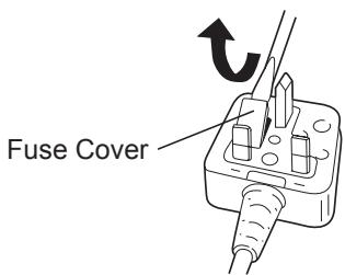
If the plug contains a removable fuse cover you must ensure that it is refitted when the fuse is replaced.
If you lose the fuse cover the plug must not be used until a replacement cover is obtained.
A replacement fuse cover can be purchased from your local Panasonic Dealer.
IF THE FITTED MOULDED PLUG IS UNSUITABLE FOR THE SOCKET OUTLET IN YOUR HOME THEN THE FUSE SHOULD BE REMOVED AND THE PLUG CUT OFF AND DISPOSED OF SAFELY. THERE IS A DANGER OF SEVERE ELECTRICAL SHOCK IF THE CUT OFF PLUG IS INSERTED INTO ANY 13 AMP SOCKET.
If a new plug is to be fitted please observe the wiring code as shown below.
If in any doubt please consult a qualified electrician.
IMPORTANT:
The wires in this mains lead are coloured in accordance with the following code:
Blue: Neutral
Brown: Live
As the colours of the wire in the mains lead of this appliance may not correspond with the coloured markings identifying the terminals in your plug, proceed as follows. The wire which is coloured BLUE must be connected to the terminal in the plug which is marked with the letter N or coloured BLACK.
The wire which is coloured BROWN must be connected to the terminal in the plug which is marked with the letter L or coloured RED. Under no circumstances should either of these wires be connected to the earth terminal of the three pin plug, marked with the letter E or the Earth Symbol 12 .
How to replace the fuse: Open the fuse compartment with a screwdriver and replace the fuse and fuse cover if it is removable.
This apparatus was produced to BS800.
natural_image
Line drawing of a hand using a power tool to lift a battery (no text or symbols)natural_image
Line drawing of a hand using a power tool to lift a battery (no text or symbols)natural_image
Line drawing of a hand using a power tool to lift a battery (no text or symbols)natural_image
Line drawing of a hand using a power tool to lift a cylindrical device (no text or symbols present)natural_image
Line drawing of a hand using a power tool to lift a cylindrical device (no text or symbols present)natural_image
Line drawing of a hand using a power tool to lift a motor, no text or symbols presentÆndring af bæltekrogens placering [Fig.8]
Overophed- ning (motor)
![PANASONIC EY79A2 - Ændring af bæltekrogens placering [Fig.8] - 1](/content/2019/08/105746/images/55c965c930057a7e1f346651c9b8ed6a9be7a57c0cb5f2a8b5cc1de7eb7d0a41.jpg)
Blinker:
Overophed- ning (batteri)
natural_image
Line drawing of a hand using a power tool to lift a battery (no text or symbols)natural_image
Line drawing of a hand using a power tool to lift a battery (no text or symbols)Lyser: Overopphe-ting (motor)
Blinker: Overopphe-ting (batteri)
natural_image
Line drawing of a hand using a power tool to lift a battery (no text or symbols)VIII. TEKNISET TIEDOT
natural_image
Line drawing of a hand using a power tool to lift a battery (no text or symbols)natural_image
Line drawing of a hand using a power tool to lift a cylindrical device (no text or symbols present)natural_image
Line drawing of a hand using a power tool to lift a battery (no text or symbols)natural_image
Line drawing of a hand using a power tool to lift a cylindrical device (no text or symbols present)Panasonic Testing Centre
Panasonic Europe Ltd. Hamburg office
Winsbergring 15,
22525 Hamburg,
Germany
Panasonic Corporation
1006,Kadoma,Osaka 571-8501,Japan
http://www.panasonic.com
EN. DE. FR. IT. NL. ES. DA. SV. NO. FI. TR. PL. CS. HU.
EY971074A202 2015.10 F
Printed in China