
EY-4550 - Power tool PANASONIC - Free user manual and instructions
Find the device manual for free EY-4550 PANASONIC in PDF.

| Product type | Cordless jigsaw |
| Brand | PANASONIC |
| Model | EY-4550 |
| Rated voltage | 18 V DC |
| Battery type | Lithium-ion (Li-ion) |
| Max cutting capacity (wood) | 65 mm |
| Max cutting capacity (mild steel) | 6 mm |
| Max cutting capacity (aluminium) | 10 mm |
| Stroke length | 25 mm |
| No load speed | 0 - 2500 min⁻¹ |
| Max blade thickness | 1.6 mm |
| Weight (with battery) | 3.35 kg |
| Overall length | 292 mm |
| Protection rating | IP56 |
| Compatible battery model | EY9L50 |
| Charger model | EY0L81 |
| Charging time (EY9L50 battery) | 50 min (usable), 65 min (full charge) |
| Orbital stroke modes | 4 positions (0 to 3) |
| Lighting | Integrated LED |
| Dust blower | Yes (on/off) |
| Vacuum adapter | Optional (EY9X016) |
| Safety | Overheat and overdischarge protection |
| Maintenance | Clean with a dry cloth; remove battery before any intervention |
| Recommended blades (metal) | EY9SXMJ0 |
| Recommended blades (wood) | EY9SXWJ2 |
| Intended use | Cutting metal, wood, and drywall |
Frequently Asked Questions - EY-4550 PANASONIC
User questions about EY-4550 PANASONIC
0 question about this device. Answer the ones you know or ask your own.
Ask a new question about this device
Download the instructions for your Power tool in PDF format for free! Find your manual EY-4550 - PANASONIC and take your electronic device back in hand. On this page are published all the documents necessary for the use of your device. EY-4550 by PANASONIC.
USER MANUAL EY-4550 PANASONIC
natural_image
Line drawing of a mechanical device with no visible text or symbolsBefore operating this unit, please read these instructions completely and save this manual for future use.
Original instructions: English Translation of the original instructions: Other languages
This tool, as a complete unit with a battery pack, satisfies appropriate IP Degrees of Protection based on the IEC regulations.
Definition of IP code
IP5X: Ingress of dust is not totally prevented, but dust shall not penetrate in a quantity to interfere with satisfactory operation of the tool or to impair safety (In case that the talcum powder under 75 m intrudes inside the tool)
IPX6: Water projected in powerful jets against the tool from any direction shall have no harmful effects (In case that, with a nozzle of 12.5 mm inner diameter, approximately 100 L/min of normal temperature water is injected to the tool for 3 minutes from 3 meter distance)
LIMITED WARRANTY
The rating of IP56 qualifies this tool for the minimum impact of water or dust, but not for the assurance of performance in such conditions. See Safety and Operating Instructions for further details for proper operation.
I. INTENDED USE
Thank you for purchasing the Panasonic Jigsaw. This jigsaw can be used with Panasonic rechargeable batteries to provide excellent cutting performance. The jigsaw is for cutting metal, wood, and drywall only.
Read the “Safety Instructions” booklet and the following before using.
II. ADDITIONAL SAFETY RULES
1) Hold tool by insulated gripping surfaces when performing an operation where the cutting tool may contact hidden wiring. Contact with a "live" wire will also make exposed metal parts of the tool "live" and shock the operator.
2) Use clamps or another practical way to secure and support the workpiece to a stable platform. Holding the work by hand or against your body leaves it unstable and may lead to loss of control.
3) Keep hands away from cutting area and blade. Keep your insulated gripping surfaces. If both hands are holding the tool, they cannot be cut by the blade.
4) Never hold piece being cut in your hands or across your leg. It is important to support the work properly to minimize body exposure or loss of control.
5) Be aware that this tool is always in an operating condition, since it does not have to be plugged into an electrical outlet.
6) Always use safety goggles or glasses with side shields. Ordinary eye or sun glasses are NOT safety glasses.
7) When this tool is used for woodworking in confined areas (e.g. indoors), wear dust mask.
8) Avoid cutting nails. Inspect workpiece for any nails and remove them before operation.
9) Do not cut oversized workpiece.
10) Check for the proper clearance beyond the workpiece before cutting so that the blade will not strike the floor, workbench, etc.
11) Hold the tool firmly.
12) Make sure the blade is not contacting the workpiece before the switch is turned on.
13) Keep hands away from moving parts.
14) Do not touch the blade or workpiece immediately after operation; they may be extremely hot and could burn your skin.
15) Never swing tool.
16) Do not use blades which are deformed or cracked.
17) Do not use blades which do not comply with the characteristics specified in these instructions.
18) Remove the battery pack from the tool body before replacement of the blade, making adjustments, or other maintenance work.
19) Wear ear protectors when using the tool for extended periods.
| Symbol | Meaning |
| V | Volts |
| --- | Direct current |
| n_0 | No load speed |
| ...min ^-1 | Revolutions orreciprocations per minutes |
| Ah | Electrical capacity ofbattery pack |
 ^(84-12) ^(84-12) | To reduce the risk ofinjury, user must readand understandinstruction manual. |
 | For indoor use only. |
WARNING:
- Do not use other than the Panasonic battery packs that are designed for use with this rechargeable tool.
- Panasonic is not responsible for any damage or accident caused by the use of the recycled battery pack and the counterfeit battery pack.
- Do not dispose of the battery pack in a fire, or expose it to excessive heat.
- Do not drive the likes of nails into the battery pack, subject it to shocks, dismantle it, or attempt to modify it.
- Do not allow metal objects to touch the battery pack terminals.
- Do not carry or store the battery pack in the same container as nails or similar metal objects.
-
Do not charge the battery pack in a high-temperature location, such as next to a fire or in direct sunlight. Otherwise, the battery may overheat, catch fire, or explode.
-
Never use other than the dedicated charger to charge the battery pack. Otherwise, the battery may leak, overheat, or explode.
- After removing the battery pack from the tool or the charger, always reattach the pack cover. Otherwise, the battery contacts could be shorted, leading to a risk of fire.
- When the Battery Pack Has Deteriorated, Replace It with a New One. Continued use of a damaged battery pack may result in heat generation, ignition or battery rupture.
III.ASEMBLY
⚠ WARNING:
To reduce the risk of injury, always remove battery pack before changing the blade.
Inspection before use
- Has the correct jigsaw blade been attached for the object to be cut?
- Has the correct stem shape and thickness of the blade been mounted?
- Check if the blade is fixed securely?
- Check if the blade is cracked or broken.
- Check that there are no foreign objects in the object to be cut.
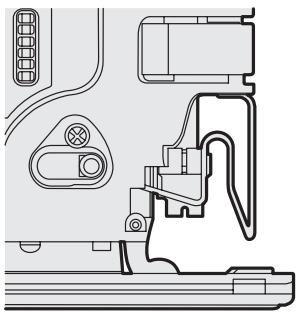
Installing and removing the blade Installation
- The dust cover is removed.
- Wipe away any cutting dust from the blade and the blade clamp bracket.
- Pull the blade Attach/Remove lever.
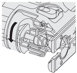
natural_image
Mechanical assembly diagram showing internal components and a directional arrow (no text or labels)- • Insert the blade into the blade clamp bracket and set the back of the blade along the roller guide so that the back of the jigsaw blade slides along the roller guide.
- Make sure the sten of blade is deep enough inserted until the blade projection is fixed by blade clamp.
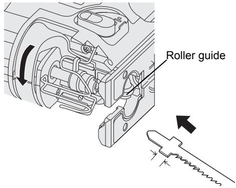
- Release the blade Attach/Remove lever.
- Check that the back of blade is along the roller guide and set straight.

WARNING:
If you do not insert the saw blade deep enough, the saw blade may be ejected unexpectedly during operation. This can be extremely dangerous.
Removal
- Pull the blade Attach/Remove lever.
- Pull out the blade.
Adjusting the base
- Use the hex wrench to loosen the base fixing screw.
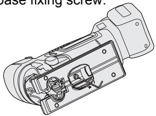
-
Move the base along the base adjustment hole to set its position. (See the diagram at right.)
-
The base can be adjusted to between 0^ and 45^ sideways and the forward/back position can also be adjusted. If tilting the base sideways, remove the dust cover first.
- Refer to the bevel index to determine the angle.
- Rip fence fixing screw should be located on the opposite side tool is beveled.
- Use the hex wrench to tighten the base fixing screw.
Position of base and purpose of use
| Base adjustment hole position | Purpose of use |
 | Normal right-angled cutting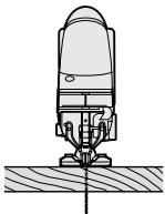 |
 | Cutting at an angle between 0° and 45°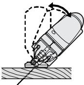 |
NOTE:
This is only a rough guide. The actual angle of the cut will be affected by factors such as the way the tool is held against the surface.
Adjusting the orbital stroke mode
- Adjust the orbital stroke mode to the object to be cut.
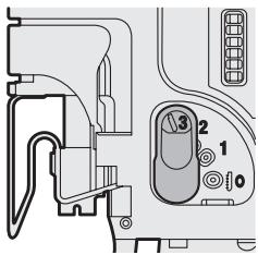
| Lever position | Blade movement | Main applications |
| 0 | [6A46]Vertical only | • Cutting hard metals such as steel• Smooth cutting of building materials and plywood boards• Cutting around small curves |
| 1 | 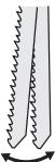 Low orbital stroke mode Low orbital stroke mode | • Cutting softer metals such as aluminum and other non-ferrous metals• Cutting hardwood, plywood boards and plastics |
| 2 | 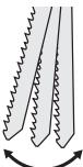 Medium orbital stroke mode Medium orbital stroke mode | • Cutting fairly soft materials• Cutting wood and composite boards• High-speed cutting of aluminum and soft steel |
| 3 | 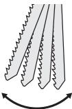 High orbital stroke mode High orbital stroke mode | • Cutting soft materials• High-speed cutting of materials such as wood, composite boards and plastics |
- If you would like to produce a cleaner finish, set the orbital stroke mode to a lower level.
Blowing lever
Select dust blow mode.
⊗: OFF ○: ON
natural_image
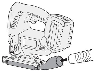
Technical line drawing of a mechanical assembly with no visible text or symbolsDust adapter for vacuum cleaner (EY9X016) (Available as an accessory, not included)
You can use a vacuum cleaner to collect cutting dust while cutting.
Installation
- Attach the hook of the dust collection adapter to the front of the base.
- Snap the rear to install it.
- Attach the hose of the vacuum cleaner.
natural_image
Line drawing of a digital camera with attached cable and connector (no text or symbols)- It is recommended to use a dust adapter for reducing the risk of damaging the surface of the object being cut.
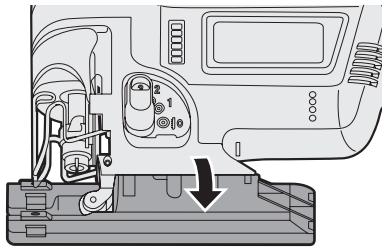
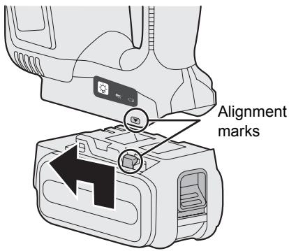
Attaching or Removing Battery Pack
1. To connect the battery pack:
Line up the alignment marks and attach the battery pack.
- Slide the battery pack until it locks into position.
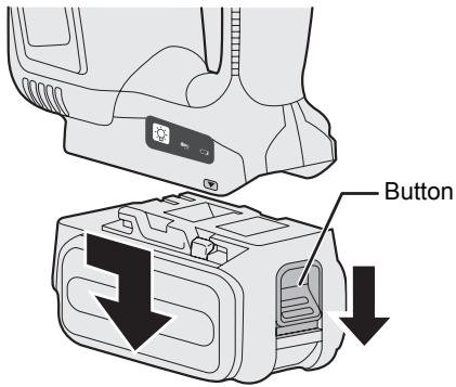
2. To remove the battery pack:
Pull the button from the front to release the battery pack.
IV. OPERATION
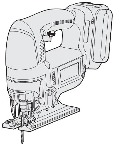
- Push the switch lock lever down, pull the power switch.
- The speed increases with the amount of depression of the power switch.
natural_image
Line drawing of a mechanical device with no visible text or symbols- Once cutting is finished, release the power switch.
- Check that the temperature of the blade has dropped sufficiently, and then remove the blade.
Cutting
NOTE:
- Check that there are no obstacles to cut underneath workpiece.
- Check that there are no objects such as nails in the material to be cut.
If the blade comes into contact with any such objects during cutting, a strong reaction force will be generated and severe injury may occur.
- Do not place your hand on the object in the direction cutting is to take place.
If this is not observed, there is a risk of injury.
- Do not touch the jigsaw blade immediately after cutting.
If this is not observed, burns may occur.
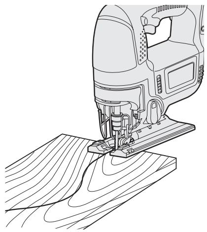
Cutting along marked lines
- Place the object to be cut onto the base, and align the blade with the marked line.
- Do not touch the blade against the object to be cut before pulling the power switch.
natural_image
Line drawing of a sewing machine needle stitching wood grain (no text or symbols)- Pull the power switch, wait until the speed has stabilized, and then place the base against the object to be cut and cut along the marked lines.
- When cutting complex shapes such as shapes with many small curves, reduce the cutting speed and the turning speed.
natural_image
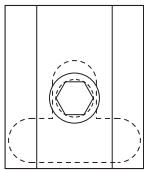
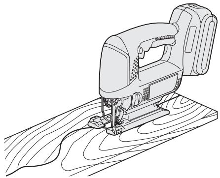
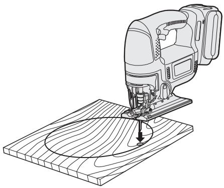
Line drawing of a manual sledge machine on a wooden surface (no text or symbols)Plunge cutting
- Make a drill hole in the section to be plunge cut in order to let the blade pass through.
- Insert the blade into a hole without touching the workpiece, and then turn on the power switch.
natural_image
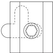
Line drawing of a hand operating a manual cutter on a wooden surface (no text or symbols)- Cut along the marked line.
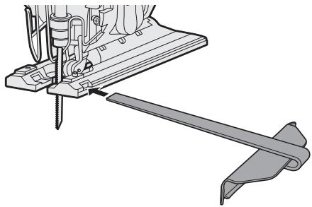
Using a rip fence
A rip fence can be used for cutting parallel lines and for cutting circles and arcs.
Installing the rip fence
- Loosen the rip fence fixing screw.
- Pass the rip fence through the mount.
- Adjust the cutting position and then tighten the fixing screw.
natural_image
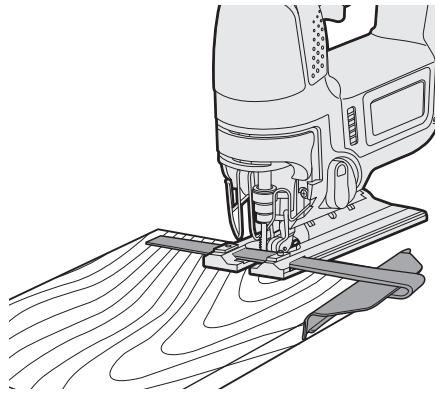
Technical line drawing of a sewing machine with base and support bracket (no text or symbols)Cutting at the same width
- Place the base onto the workpiece so that the edge of the rip fence and workpiece are put together.
natural_image
Line drawing of a sewing machine needle stitching wood grain (no text or symbols)- Without letting the blade touch the workpiece, turn on the power switch.
- Face the rip fence firmly to the workpiece to cut parallel line.
⚠ WARNING:
Do not inhale any smoke emitted from the tool or battery pack as it may be harmful.
CAUTION:
Do not use the tool in a manner that causes the motor to lock up. Doing so may damage the tool and battery pack, resulting in smoke or fire.
Control Panel
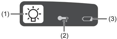
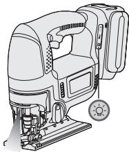
(1) LED light
natural_image
Line drawing of a sewing machine with a sun icon (no text or symbols)Before the use of LED light, always pull the power switch once.
Press the LED light button.
The light illuminates with very low current, and it does not adversely affect the performance of the driver during use or its battery capacity.

CAUTION:
- The built-in LED light is designed to illuminate the small work area temporarily.
- Do not use it as a substitute for a regular flashlight, since it does not have enough brightness.
- LED light turns off when the tool has not been used for 5 minutes.
Caution : DO NOT STARE INTO BEAM. Use of controls or adjustments or performance of procedures other than those specified herein may result in hazardous radiation exposure.
(2) Overheat warning lamp
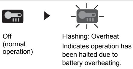
The overheating protection feature halts operation to protect the battery pack in the event of overheating. The overheat warning lamp on the control panel flashes when this feature is active.
- If the overheating protection feature activates, allow the driver to cool thoroughly (at least 30 minutes). The battery is ready for use when the overheat warning lamp goes out.
- Avoid using the driver in a way that causes the overheating protection feature to activate repeatedly.
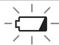
(3) Battery low warning lamp
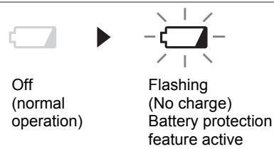
Excessive (complete) discharging of lithium ion batteries shortens their service life dramatically. The tool includes a battery protection feature designed to prevent excessive discharging of the battery pack.
- The battery protection feature activates immediately before the battery loses its charge, causing the battery low warning lamp to flash.
- If you notice the battery low warning lamp flashing, charge the battery pack immediately.
[Battery Pack]
For Appropriate Use of Battery pack
Li-ion Battery pack
- For optimum battery life, store the Li-ion battery pack following use without charging it.
- When charging the battery pack, confirm that the terminals on the battery charger are free of foreign substances such as dust and water etc. Clean the terminals before charging the battery pack if any foreign substances are found on the terminals.
The life of the battery pack terminals may be affected by foreign substances such as dust and water etc. during operation.
- When battery pack is not in use, keep it away from other metal objects like: paper clips, coins, keys, nails, screws, or other small metal objects that can make a connection from one terminal to another.
Shorting the battery terminals together may cause sparks, burns or a fire.
- When operating the battery pack, make sure the work place is well ventilated.
- When the battery pack is removed from the main body of the tool, replace the battery pack cover immediately in order to prevent dust or dirt from contaminating the battery terminals and causing a short circuit.
natural_image
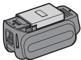
Illustration of a gray electronic device casing with internal components (no text or symbols)Battery Pack Life
The rechargeable batteries have a limited life. If the operation time becomes extremely short after recharging, replace the battery pack with a new one.
Battery Recycling
ATTENTION:
For environmental protection and recycling of materials, be sure that it is disposed of at an officially assigned location, if there is one in your country.
[Battery Charger]
Charging
Cautions
- If the temperature of the battery pack falls approximately below -10^ (14°F), charging will automatically stop to prevent degradation of the battery.
- The ambient temperature range is between 0^ (32°F) and 40^ (104°F). If the battery pack is used when the battery temperature is below 0^ (32°F), the tool may fail to function properly.
- When charging a cool battery pack (below 0^ (32^) ) in a warm place, leave the battery pack at the place and wait for more than one hour to warm up the battery to the level of the ambient temperature.
- Cool down the charger when charging more than two battery packs consecutively.
- Do not insert your fingers into contact hole, when holding charger or any other occasions.
To prevent the risk of fire or damage to the battery charger.
- Do not use power source from an engine generator.
- Do not cover vent holes on the charger and the battery pack.
- Unplug the charger when not in use.
Li-ion Battery Pack
NOTE:
Your battery pack is not fully charged at the time of purchase. Be sure to charge the battery before use.
Battery charger
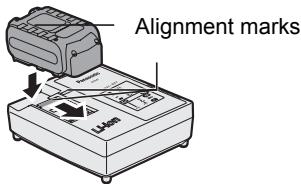
-
Plug the charger into the AC outlet.
-
Insert the battery pack firmly into the charger.
-
Line up the alignment marks and place the battery onto the dock on the charger.
-
Slide forward in the direction of the arrow.
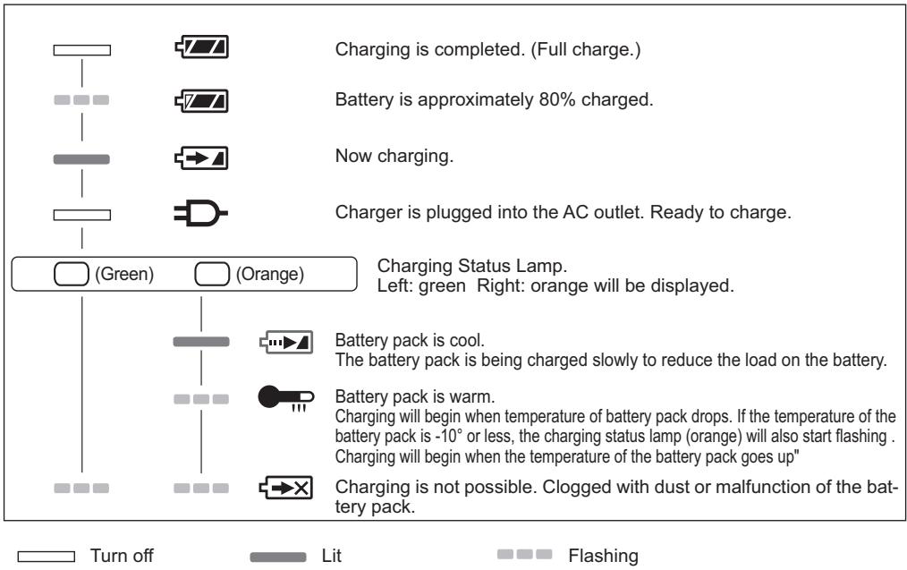
- During charging, the charging lamp will be lit.
When charging is completed, an internal electronic switch will automatically be triggered to prevent overcharging.
- Charging will not start if the battery pack is warm (for example, immediately after heavy-duty operation).
The orange standby lamp will be flashing until the battery cools down.
Charging will then begin automatically.
- The charge lamp (green) will flash slowly once the battery is approximately 80% charged.
5 When charging is completed, the charging lamp in green color will turn off.
- If the temperature of the battery pack is 0^ C or less, charging takes longer to fully charge the battery pack than the standard charging time.
Even when the battery is fully charged, it will have approximately 50% of the power of a fully charged battery at
normal operating temperature.
-
Consult an authorized dealer if the charging lamp (green) does not turn off.
-
If a fully charged battery pack is inserted into the charger again, the charging lamp lights up. After several minutes, the charging lamp in green color will turn off.
LAMP INDICATIONS
Information for Users on Collection and Disposal of Old Equipment and used Batteries
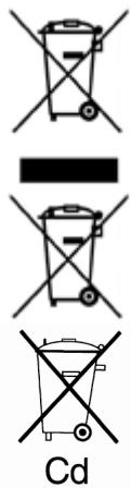
These symbols on the products, packaging, and/or accompanying documents mean that used electrical and electronic products and batteries should not be mixed with general household waste.
For proper treatment, recovery and recycling of old products and used batteries, please take them to applicable collection points, in accordance with your national legislation and the Directives 2002/96/EC and 2006/66/EC.
By disposing of these products and batteries correctly, you will help to save valuable resources and prevent any potential negative effects on human health and the environment which could otherwise arise from inappropriate waste handling.
For more information about collection and recycling of old products and batteries, please contact your local municipality, your waste disposal service or the point of sale where you purchased the items.
Penalties may be applicable for incorrect disposal of this waste, in accordance with national legislation.
For business users in the European Union
If you wish to discard electrical and electronic equipment, please contact your dealer or supplier for further information.
[Information on Disposal in other Countries outside the European Union]
These symbols are only valid in the European Union. If you wish to discard these items, please contact your local authorities or dealer and ask for the correct method of disposal.
Note for the battery symbol (bottom two symbol examples):
This symbol might be used in combination with a chemical symbol. In this case it complies with the requirement set by the Directive for the chemical involved.
V. MAINTENANCE
- Use only a dry, soft cloth for wiping the unit. Do not use a damp cloth, thinner, benzine, or other volatile solvents for cleaning.
- In the event that the inside of the tool or battery pack is exposed to water, drain and allow to dry as soon as possible. Carefully remove any dust or iron filings that collect inside the tool. If you experience any problems operating the tool, consult with a repair shop.
VI. ACCESSORIES
CAUTION:
- The use of any accessories not specified in this manual may result in fire, electric shock, or personal injury. Use recommended accessories only.
Metal Blade
• EY9SXMJ0
For cutting metal in general
Wood Blade
• EY9SXWJ2
For cutting wood in general
For convenience of rip cuts and repeated cut of same width.
Dust Adaptor for Vacuum Cleaner (Optional accessory)
• EY9X016
VII. SPECIFICATIONS
MAIN UNIT
| Model | EY4550 | |
| Motor | 18 V | |
| Max thickness of mounting blade | 1.6 mm (1/16") | |
| Length of strokes | 25 mm (1.0") | |
| Strokes per minute | 0 - 2500 /min | |
| Maximum cutting capacities | Wood | 65mm(2-9/16") |
| Mild steel | 6mm(1/4") | |
| Aluminum | 10mm(3/8") | |
| Overall length | 292 mm (10-1/2") | |
| Weight (with battery pack) | 3.35kg(7.5lbs) | |
| Noise, Vibration | See the uncluded sheet | |
BATTERY PACK
| Model | EY9L50 |
| Storage battery | Li-ion |
| Battery voltage | 18V DC(3.6V x 10 cells) |
BATTERY CHARGER
| Model | EY0L81 |
| Electrical rating | See the rating plate on the bottom of the charger. |
| Charging time | EY9L50 |
| Usable: 50 min. | |
| Full: 65 min. |
NOTE: This chart may include models that are not available in your area. Please refer to the latest general catalogue.
NOTE: For the dealer name and address, please see the included warranty card.
ONLY FOR U. K.
VIII. ELECTRICAL PLUG INFORMATIO
FOR YOUR SAFETY PLEASE READ THE FOLLOWING TEXT CAREFULLY
This appliance is supplied with a moulded three pin mains plug for your safety and convenience.
A 5 amp fuse is fitted in this plug.
Should the fuse need to be replaced please ensure that the replacement fuse has a rating of 5 amp and that it is approved by ASTA or BSI to BS1362.
Check for the ASTA mark ◆ or the BSI mark 🍽 on the body of the fuse.
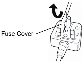
If the plug contains a removable fuse cover you must ensure that it is refitted when the fuse is replaced.
If you lose the fuse cover the plug must not be used until a replacement cover is obtained.
A replacement fuse cover can be purchased from your local Panasonic Dealer.
IF THE FITTED MOULDED PLUG IS UNSUITABLE FOR THE SOCKET OUTLET IN YOUR HOME THEN THE FUSE SHOULD BE REMOVED AND THE PLUG CUT OFF AND DISPOSED OF SAFELY.
THERE IS A DANGER OF SEVERE ELECTRICAL SHOCK IF THE CUT OFF PLUG IS INSERTED INTO ANY 13 AMP SOCKET.
If a new plug is to be fitted please observe the wiring code as shown below.
If in any doubt please consult a qualified electrician.
IMPORTANT:
The wires in this mains lead are coloured in accordance with the following code:
Blue: Neutral
Brown: Live
As the colours of the wire in the mains lead of this appliance may not correspond with the coloured markings identifying the terminals in your plug, proceed as follows.
The wire which is coloured BLUE must be connected to the terminal in the plug which is marked with the letter N or coloured BLACK.
The wire which is coloured BROWN must be connected to the terminal in the plug which is marked with the letter L or coloured RED.
Under no circumstances should either of these wires be connected to the earth terminal of the three pin plug, marked with the letter E or the Earth Symbol 12 .
How to replace the fuse: Open the fuse compartment with a screwdriver and replace the fuse and fuse cover if it is removable.
This apparatus was produced to BS800.
natural_image
Mechanical assembly diagram showing internal components and a directional arrow (no text or labels)natural_image
Technical line drawing of a mechanical device with internal components (no text or symbols)natural_image
Diagram of a device's internal components with a downward arrow indicating a component (no text or symbols present)natural_image
Technical line drawing of a mechanical assembly with no visible text or symbolsnatural_image
Technical line drawing of a mechanical device with attached cable (no text or symbols)natural_image
Line drawing of a Jigsaw kit with handle and mounting base (no text or symbols)natural_image
Line drawing of a manual sewing machine on a wooden surface (no text or symbols)natural_image
Line drawing of a manual sewing machine on a wooden surface (no text or symbols)Einstechschneiden
natural_image
Line drawing of a hand operating a wooden saw machine on a wooden base (no text or symbols)natural_image
Technical line drawing of a mechanical assembly with no visible text or symbolsnatural_image
Line drawing of a sewing machine needle stitching wood grain (no text or symbols)natural_image
Line drawing of a sewing machine with no visible text or symbolsnatural_image
Illustration of a gray electronic device casing with internal components (no text or symbols)natural_image
Mechanical assembly diagram showing internal components and motion arrows (no text or labels)natural_image
Technical line drawing of an internal mechanical device with no visible text or symbolsnatural_image
Technical diagram of a device's internal components with no visible text or symbolsnatural_image
Technical line drawing of a mechanical assembly with no visible text or symbolsnatural_image
Line drawing of a mechanical device with a cable inserted, showing no text or symbols.natural_image
Line drawing of a Jigsaw machine tool (no text or symbols)natural_image
Line drawing of a hand tool sewing on wood, showing mechanical components and base (no text or symbols)natural_image
Line drawing of a sewing machine on a wooden surface (no text or symbols)Sciage en plongée
natural_image
Line drawing of a hand-painted manual sewing machine on a wooden base (no text or symbols)natural_image
Technical line drawing of a mechanical assembly with no visible text or symbolsnatural_image
Line drawing of a sewing machine needle stitching wood grain (no text or symbols)natural_image
Line drawing of a sewing machine with no visible text or symbolsnatural_image
Illustration of a mechanical device housing with no visible text or symbolsnatural_image
Mechanical assembly diagram showing internal components and motion arrows (no text or labels)natural_image
Technical line drawing of a mechanical device with internal components (no text or symbols)natural_image
Diagram of a camera module with labeled parts and an arrow indicating a component (no text or symbols present)natural_image
Technical line drawing of a mechanical assembly with no visible text or symbolsnatural_image
Line drawing of a camera with attached cable and connector (no text or symbols)natural_image
Line drawing of a mechanical device with a lever and base mount (no text or symbols)natural_image
Line drawing of a sewing machine needle stitching wood grain (no text or symbols)natural_image
Line drawing of a manual sledge machine on a wooden surface (no text or symbols)Taglio dal centro
natural_image
Line drawing of a hand operating a manual cutter on a wooden surface (no text or symbols)natural_image
Technical line drawing of a mechanical assembly with no visible text or symbolsnatural_image
Line drawing of a sewing machine needle stitching wood grain (no text or symbols)natural_image
Line drawing of a sewing machine with no visible text or symbolsnatural_image
Illustration of a mechanical component with no visible text or symbolsnatural_image
Mechanical assembly diagram showing internal components and motion direction (no text or labels)natural_image
Technical line drawing of an internal mechanical device with no visible text or symbolsnatural_image
Diagram of a device interior showing internal components and a downward arrow indicating a specific location (no text or symbols present)natural_image
Technical line drawing of a mechanical assembly with no visible text or symbolsnatural_image
Line drawing of a mechanical device with a cable and connector (no text or symbols)natural_image
Line drawing of a Jigsaw machine tool (no text or symbols)natural_image
Line drawing of a sewing machine needle stitching wood grain (no text or symbols)natural_image
Line drawing of a manual sewing machine on a wooden surface (no text or symbols)natural_image
Line drawing of a hand operating a manual saw on a wooden surface (no text or symbols)natural_image
Technical line drawing of a sewing machine with attached support bracket (no text or symbols)natural_image
Line drawing of a sewing machine needle stitching wood grain on a cutting board (no text or symbols)natural_image
Technical line drawing of a mechanical device with no visible text or symbolsnatural_image
3D rendering of a mechanical housing or enclosure component (no text or symbols visible)natural_image
Mechanical assembly diagram showing internal components with a directional arrow (no text or labels)natural_image
Technical line drawing of a mechanical device with internal components (no text or symbols)natural_image
Diagram of a camera module with labeled parts and an arrow indicating a component (no text or symbols present)natural_image
Technical line drawing of a mechanical assembly with no visible text or symbolsnatural_image
Line drawing of a camera with attached cable and connector (no text or symbols)natural_image
Line drawing of a Jigsaw machine tool (no text or symbols)natural_image
Line drawing of a sewing machine needle stitching wood grain (no text or symbols)natural_image
Line drawing of a manual sledge machine on a wooden surface (no text or symbols)Corte inmerso
natural_image
Line drawing of a hand operating a wooden saw machine on a workbench (no text or symbols)natural_image
Technical line drawing of a sewing machine's base and support structure (no text or symbols)natural_image
Line drawing of a sewing machine needle stitching wood grain (no text or symbols)natural_image
Line drawing of a sewing machine with no visible text or symbolsnatural_image
Illustration of a gray electronic device casing with internal components (no text or symbols)natural_image
Mechanical assembly diagram showing internal components and motion arrows (no text or labels)natural_image
Technical line drawing of an internal mechanical device with no visible text or symbolsnatural_image
Technical diagram of a device's internal components with no visible text or symbolsnatural_image
Technical line drawing of a mechanical assembly with no visible text or symbolsnatural_image
Line drawing of a camera with attached cable and connector (no text or symbols)natural_image
Line drawing of a mechanical device with no visible text or symbolsnatural_image
Line drawing of a Jigsaw machine stitching wood grain (no text or symbols)natural_image
Line drawing of a manual sledge machine on a wooden surface (no text or symbols)Indstiksskæring
natural_image
Line drawing of a hand tool cutting through wood, showing a circular cutter or cutterhead (no text or symbols present)natural_image
Technical line drawing of a mechanical assembly with no visible text or symbolsSkæring i den samme bredde
natural_image
Line drawing of a sewing machine needle stitching wood grain (no text or symbols)natural_image
Line drawing of a sewing machine with no visible text or symbolsnatural_image
Illustration of a mechanical component with no visible text or symbolsAkuens levetid
natural_image
Mechanical assembly diagram showing internal components and motion direction (no text or labels)natural_image
Technical line drawing of an internal mechanical device with no visible text or symbolsnatural_image
Technical diagram of a device's internal components with no visible text or symbolsnatural_image
Technical line drawing of a mechanical assembly with no visible text or symbolsnatural_image
Line drawing of a mechanical device with a coiled cable and a power tool inserted (no text or symbols)natural_image
Line drawing of a mechanical device with no visible text or symbolsnatural_image
Line drawing of a Jigsaw machine stitching wood grain (no text or symbols)natural_image
Line drawing of a manual sledge machine on a wooden surface (no text or symbols)Instickssågning
natural_image
Line drawing of a hand operating a manual sledge tool on a wooden surface (no text or symbols)natural_image
Technical line drawing of a sewing machine with base and support bracket (no text or symbols)natural_image
Line drawing of a sewing machine needle stitching wood grain (no text or symbols)natural_image
Technical line drawing of a sewing machine with no visible text or symbolsnatural_image
Illustration of a gray plastic electronic device casing with internal components (no text or symbols)natural_image
Symbol of a trash bin with crossed lines indicating no waste, and a solid black rectangle below (no text or labels)natural_image
Mechanical assembly diagram showing internal components and motion arrows (no text or labels)natural_image
Technical line drawing of an internal mechanical device with no visible text or symbolsnatural_image
Diagram of a camera module with labeled ports and a downward arrow indicating a component (no text or symbols present)natural_image
Technical line drawing of a mechanical assembly with no visible text or symbolsnatural_image
Line drawing of a mechanical device with a cable inserted, no text or symbols present2. Fjerne batteripakken:
natural_image
Line drawing of a mechanical device with no visible text or symbolsnatural_image
Line drawing of a Jigsaw machine stitching wood grain on a wooden surface (no text or symbols)natural_image
Line drawing of a wooden trowel machine on a wooden base (no text or symbols)Dykkskjæring
natural_image
Line drawing of a manual sewing machine cutting through wood, showing needle insertion (no text or symbols)- Skjær langs den merkete linjen.
Bruke et parallellanslag
natural_image
Technical line drawing of a mechanical assembly with no visible text or symbolsnatural_image
Line drawing of a sewing machine needle stitching wood grain (no text or symbols)natural_image
Line drawing of a sewing machine with no visible text or symbols(2) Varsellampe for overoppheting

Av
(normal
operation)


Av
(normal
operation)

Blinker
(Ingen lading)
Battery protection
feature active
natural_image
Illustration of a mechanical component with no visible text or symbolsnatural_image
Symbol of a trash bin with crossed lines indicating no waste, and a solid black rectangle below (no text or labels)Slike symboler på produkter, emballasje, og/eller på medfølgende dokumenter betyr at brukte elektriske/elektroniske produkter og batterier ikke må blandes med vanlig husholdningsavfall.
natural_image
Technical line drawing of a mechanical assembly with no visible text or symbolsnatural_image
Technical line drawing of an internal mechanical device with no visible text or symbolsnatural_image
Diagram of a device interior showing internal components and a downward arrow indicating a specific location (no text or symbols present)natural_image
Technical diagram of a mechanical device with labeled parts (no readable text or symbols)natural_image
Technical line drawing of a mechanical assembly with no visible text or symbolsnatural_image
Line drawing of a camera with attached cable and connector (no text or symbols)natural_image
Line drawing of a mechanical device with no visible text or symbolsnatural_image
Line drawing of a sewing machine needle stitching wood grain (no text or symbols)natural_image
Line drawing of a manual sledge machine on a wooden surface (no text or symbols)Läpisahaus
natural_image
Line drawing of a hand operating a wooden saw machine with a curved tool path (no text or symbols)natural_image
Technical line drawing of a sewing machine's base and support structure (no text or symbols)natural_image
Line drawing of a sewing machine needle stitching wood grain (no text or symbols)natural_image
Illustration of a sewing machine with a solar panel indicator (no text or symbols)natural_image
Illustration of a gray electronic device casing with internal components (no text or symbols)Akun kestoikä
natural_image
Symbol of a trash bin with no text or labels, accompanied by two crossed x- and one solid black rectangle below (no text or symbols present)EN. GR. FR. IT. ND. ES. DN. SW. NR. FN
EY971045501 2011.03
Printed in China
- Original instructions: English Translation of the original instructions: Other languages
- Definition of IP code
- LIMITED WARRANTY
- INTENDED USE
- ADDITIONAL SAFETY RULES
- WARNING:
- III.ASEMBLY
- ⚠ WARNING:
- Inspection before use
- Installing and removing the blade Installation
- Removal
- Adjusting the base
- NOTE:
- Adjusting the orbital stroke mode
- Blowing lever
- Installation
- Attaching or Removing Battery Pack
- To connect the battery pack:
- To remove the battery pack:
- OPERATION
- Cutting
- Cutting along marked lines
- Plunge cutting
- Using a rip fence
- Installing the rip fence
- Cutting at the same width
- CAUTION:
- Control Panel
- [Battery Pack]
- For Appropriate Use of Battery pack
- Li-ion Battery pack
- Battery Pack Life
- Battery Recycling
- ATTENTION:
- [Battery Charger]
- Charging
- Cautions
- Battery charger
- LAMP INDICATIONS
- Information for Users on Collection and Disposal of Old Equipment and used Batteries
- For business users in the European Union
- [Information on Disposal in other Countries outside the European Union]
- Note for the battery symbol (bottom two symbol examples):
- MAINTENANCE
- ACCESSORIES
- SPECIFICATIONS
- ONLY FOR U. K.
- ELECTRICAL PLUG INFORMATIO
- FOR YOUR SAFETY PLEASE READ THE FOLLOWING TEXT CAREFULLY
- IMPORTANT:
- Einstechschneiden
- Sciage en plongée
- Taglio dal centro
- Corte inmerso
- Indstiksskæring
- Skæring i den samme bredde
- Akuens levetid
- Instickssågning
- Fjerne batteripakken:
- Dykkskjæring
- Bruke et parallellanslag
- Varsellampe for overoppheting
- Läpisahaus
- Akun kestoikä
Brand : PANASONIC
Model : EY-4550
Category : Power tool