
EY7440 - Power tool PANASONIC - Free user manual and instructions
Find the device manual for free EY7440 PANASONIC in PDF.

| Product Type | Cordless Drill Driver |
| Brand | Panasonic |
| Model | EY7440 |
| Power Supply | Li-ion Battery 14.4 V DC, capacity 3 Ah (model EY9L40) |
| No-load Speed | Low: 60 - 400 min⁻¹ ; High: 200 - 1350 min⁻¹ |
| Maximum Torque | 26 N·m (low speed) ; 8.8 N·m (high speed) |
| Clutch Torque Setting | 18 settings, from 0.5 to 4.4 N·m |
| Chuck Capacity | 1.5 mm - 13 mm (keyless chuck) |
| Recommended Drilling Capacities | Wood: 35 mm ; Metal: 13 mm |
| Recommended Screwing Capacities | Machine screw M5 ; Wood screw 6.8 mm ; Self-tapping screw 6 mm |
| Overall Length | 191 mm |
| Weight (with battery) | 1.6 kg |
| Main Features | Keyless chuck, LED light, belt hook, electronic brake, protection against overheating and excessive discharge |
| Maintenance and Cleaning | Clean with a dry cloth; do not use water or solvent |
| Safety | Wear safety glasses; do not touch metal parts when drilling into walls; lock the switch in the central position for transport |
| Spare Parts and Repairability | Only use compatible accessories; contact an authorized dealer for any repairs |
| Charger | Model EY0L80, charging time 35 min (useful) / 50 min (full) |
| General Information | Rechargeable Li-ion battery; recycle according to local regulations; do not dispose of with household waste |
Frequently Asked Questions - EY7440 PANASONIC
User questions about EY7440 PANASONIC
0 question about this device. Answer the ones you know or ask your own.
Ask a new question about this device
Download the instructions for your Power tool in PDF format for free! Find your manual EY7440 - PANASONIC and take your electronic device back in hand. On this page are published all the documents necessary for the use of your device. EY7440 by PANASONIC.
USER MANUAL EY7440 PANASONIC
Cordless Drill & Driver
Akku-Bohrschrauber
natural_image
Line drawing of a handheld electric drill press (no text or symbols)Before operating this unit, please read these instructions completely and save this manual for future use.
Read the Safety Instructions booklet and the following before using.
I. ADDITIONAL SAFETY RULES
1) Wear ear protectors when using the tool for extended periods.
Prolonged exposure to high intensity noise can cause hearing loss.
2) Be aware that this tool is always in an operating condition, since it does not have to be plugged into an electrical outlet.
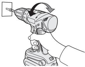
3) When drilling or driving into walls, floors, etc., "live" electrical wires may be encountered. DO NOT TOUCH THE CHUCK OR ANY FRONT METAL PARTS OF THE TOOL! Hold the tool only by the plastic handle to prevent electric shock in case you drill or drive into a "live" wire.
4) If the bit becomes jammed, immediately turn the trigger switch off to prevent an overload, which can damage the battery pack or motor.
Use reverse motion to loosen jammed bits.
5) Do NOT operate the Forward/Reverse lever when the trigger switch is on. The battery will discharge rapidly and damage to the unit may occur.
6) During charging, the charger may become slightly warm. This is normal. Do NOT charge the battery for a long period.
7) When storing or carrying the tool, set the Forward/Reverse lever to the center position (switch lock).
8) Do not strain the tool by holding the speed control trigger halfway (speed control mode) so that the motor stops.
9) Do not operate the speed selector switch (LOW-HIGH) while pulling on the speed control trigger. This can cause the rechargeable battery to wear quickly or damage the internal mechanism of the motor.
| Symbol | Meaning |
| V | Volts |
| —— | Direct current |
| no | No load speed |
| .../min | Revolutions or reciprocations per minutes |
| Ah | Electrical capacity of battery pack |
 | Rotation only |
 | Read the operating instructions before use. |
| [SDHT] | For indoor use only. |
II. ASSEMBLY
Attaching or Removing Bit
NOTE:
When attaching or removing a bit, disconnect battery pack from tool or place the switch in the center position (switch lock).
This tool is equipped with a keyless drill chuck.
1. Attachment
Insert the bit and turn the lock collar clockwise (looking from the front) to tighten firmly until it stops clicking.
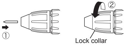
2. Removal
Turn the lock collar counterclockwise (looking from the front), then remove the bit.

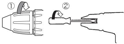
NOTE:
If excessive play occurs in the chuck, secure the drill in place and ① open the chuck jaws by turning the lock collar and ② tighten the screw (left-handed screw) with a screwdriver by turning it counterclockwise (viewed from the front).
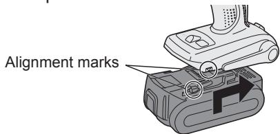
Attaching or Removing Battery Pack
1. To connect the battery pack:
Line up the alignment marks and attach the battery pack.
- Slide the battery pack until it locks into position.
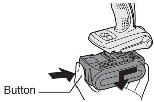
2. To remove the battery pack:
Push on the button from the front to release the battery pack.
III. OPERATION
[Main Body]
Switch Operation
- The speed increases with the amount of depression of the trigger. When beginning work, depress the trigger slightly to start the rotation slowly.
- A feedback electronic controller is used to give a strong torque even in low speed.
- The brake operates when the trigger is released and the motor stops immediately.
NOTE:
When the brake operates, a braking sound may be heard. This is normal.
Switch and Forward/Reverse Lever Operation
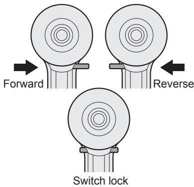
CAUTION:
To prevent damage, do not operate Forward/Reverse lever until the bit comes to a complete stop.
Forward Rotation Switch Operation
- Push the lever for forward rotation.
- Depress the trigger switch slightly to start the tool slowly.
- The speed increases with the amount of depression of the trigger for efficient tightening of screws and drilling. The brake operates and the
chuck stops immediately when the trigger is released.
- After use, set the lever to its center position (switch lock).
Reverse Rotation Switch Operation
- Push the lever for reverse rotation. Check the direction of rotation before use.
- Depress the trigger switch slightly to start the tool slowly.
- After use, set the lever to its center position (switch lock).
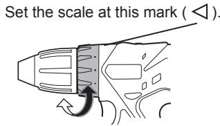
Clutch Torque Setting
Adjust the torque to one of the 18 clutch settings or “#” position.
CAUTION:
Test the setting before actual operation.
Speed Selection
Choose a low or high speed to suit the use.
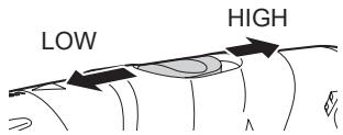
The more the variable speed control trigger is pulled, the higher the speed becomes.
CAUTION:
- Check the speed selector switch before use.
- Use at low speed when high torque is needed during operation. (Using at high speed when high torque is required may cause a motor breakdown.)
- Do not operate the speed selector switch (LOW-HIGH) while pulling on the speed control trigger. This
can cause the rechargeable battery to wear quickly or damage the internal mechanism of the motor.
*See specifications for "RECOMMENDED CAPACITIES".
NOTE:
When the brake operates, a braking sound may be heard. This sound indicates engagement of the bit lock.
CAUTION:
- To prevent excessive temperature increase of the tool surface, do not operate the tool continuously using two or more battery packs. The tool needs cool-off time before switching to another pack.
- Do not close up vent holes on the sides of the body during operation. Otherwise, the machine function is adversely affected to cause a failure.
- Do NOT strain the tool (motor). This may cause damage to the unit.
- Use the tool in such a way as to prevent the air from the body vent holes from blowing directly onto your skin. Otherwise, you may get burned.
Bit-locking Function
-
With the trigger switch not engaged and a screwdriver bit locked in place, the tool can be used as a manual screwdriver (up to 22.6 N·m, 230 kgf·cm, 199 in-lbs).
There will be a little play in the chuck, but this is not a malfunction. -
This feature is handy for tightening screws that require more torque than the maximum torque of the driver (position on the clutch), for confirming the tightness of a screw or to loosen an extremely tight screw.
natural_image
Line drawing of a hand using a drill bit to lift a power tool (no text or symbols present)How to Use the Belt Hook

WARNING!
- Be sure to attach the belt hook securely to the main unit with the screw firmly fastened. When the belt hook is not firmly attached to the main unit, the hook may disconnect and the main unit may fall. This may result in an accident or injury.
- Periodically check screw for tightness. If found to be loose, tighten firmly.
- Be sure to attach the belt hook firmly and securely onto a waist belt or other belt. Pay attention that the unit does not slip off the belt. This may result in an accident or injury.
- When the main unit is held by the belt hook, avoid jumping or running with it. Doing so may cause the hook to slip and the main unit may fall.
This may result in an accident or injury.
- When the belt hook is not used, be sure to return it to the storing position. The belt hook may catch on something.
This may result in an accident or injury.
- When the unit is hooked onto the waist belt by the belt hook, do not attach driver bits to the unit. A sharp edge object, such as a drill bit, may cause injury or an accident.
To Set the Belt Hook Angle Position
-
Slide the belt hook lock lever ① and hold it to unlock the belt hook.
-
Pull the belt hook from storing position ② and set it.
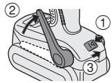
-
Release the belt hook lock lever to lock the angle of belt hook.
-
Make sure the belt hook is firmly locked. Also make sure the belt hook is firmly locked into position ③.
- The belt hook cannot be locked in this position. Firmly lock it into position before use.
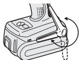
To return the belt hook to the storing position, follow step 1. and 2. above, then lower the belt hook.
To secure the lock, follow 3 and 4 above.
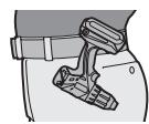
To Change the Belt Hook Location Side
The belt hook can be attached to either side of the unit.
natural_image
Line drawing of a mechanical device with a rotary knob and scroll wheel (no text or symbols)- Set the belt hook at storing position.
- Loosen the screw turning it counter-clockwise, using a flat metal or a flat blade screw driver.
- Take out the belt hook and insert into the other side of the slot on the main unit.
- Fasten the screw firmly, turning it clockwise.
The belt hook can be taken out from the main unit only when it is at storing position.
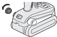
Control Panel
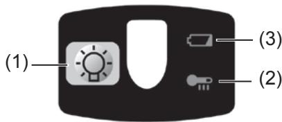
(1) LED light
natural_image
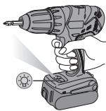
Illustration of a hand holding a drill pen and a battery with a sun icon (no text or symbols)Pressing ⚙ toggles the LED light on and off.
The light illuminates with very low current, and it does not adversely affect the performance of the driver during use or its battery capacity.
CAUTION:
- The built-in LED light is designed to illuminate the small work area temporarily.
- Do not use it as a substitute for a regular flashlight, since it does not have enough brightness.
This product has the built-in LED light. This product is classified into “Class 1 LED Product” to EN 60825-1.
Class 1 LED Product
Caution : DO NOT STARE INTO BEAM.
(2) Overheat warning lamp

Off (normal operation)

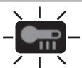
Flashing: Overheat Indicates operation has been halted due to battery overheating.
The overheating protection feature halts driver operation to protect the battery pack in the event of overheating. The overheat warning lamp on the control panel flashes when this feature is active.
- If the overheating protection feature activates, allow the driver to cool thoroughly (at least 30 minutes). The driver is ready for use when the overheat warning lamp goes out.
- Avoid using the driver in a way that causes the overheating protection feature to activate repeatedly.
(3) Battery low warning lamp

Off (normal operation)

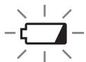
Flashing (No charge) Battery protection feature active
Excessive (complete) discharging of lithium ion batteries shortens their service life dramatically. The driver includes a battery protection feature designed to prevent excessive discharging of the battery pack.
- The battery protection feature activates immediately before the battery loses its charge, causing the battery low warning lamp to flash.
- If you notice the battery low warning lamp flashing, charge the battery pack immediately.
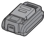
[Battery Pack]
For Appropriate Use of Battery pack
Li-ion Battery pack (EY9L40)
- For optimum battery life, store the Li-ion battery pack following use without charging it.
- The ambient temperature range is between 0^ (32°F) and 40^ (104°F). If the battery pack is used when the battery temperature is below 0^ (32°F), the tool may fail to function properly.
- When battery pack is not in use, keep it away from other metal objects like: paper clips, coins, keys, nails, screws, or other small metal objects that can make a connection from one terminal to another.
Shorting the battery terminals together may cause sparks, burns or a fire. - When operating the battery pack, make sure the work place is well ventilated.
- When the battery pack is removed from the main body of the tool, replace the battery pack cover immediately in order to prevent dust or dirt from contaminating the battery terminals and causing a short circuit.
Battery Pack Life
The rechargeable batteries have a limited life. If the operation time becomes extremely short after recharging, replace the battery pack with a new one.
Battery Recycling
ATTENTION:
For environmental protection and recycling of materials, be sure that it is disposed of at an officially assigned location, if there is one in your country.
[Battery Charger]
Charging
Common Cautions for the Li-ion/Ni-MH/Ni-Cd Battery Pack
NOTE:
- When charging a cool battery pack (below 0^ (32^) ) in a warm place, leave the battery pack at the place and wait for more than one hour to warm up the battery to the level of the ambient temperature. Otherwise battery pack may not be fully charged.
- Cool down the charger when charging more than two battery packs consecutively.
- Do not insert your fingers into contact hole, when holding charger or any other occasions.
CAUTION:
To prevent the risk of fire or damage to the battery charger.
- Do not use power source from an engine generator.
- Do not cover vent holes on the charger and the battery pack.
- Unplug the charger when not in use.
Li-ion Battery Pack
NOTE:
Your battery pack is not fully charged at the time of purchase. Be sure to charge the battery before use.
Battery charger (EY0L80)
- Plug the charger into the AC outlet.
NOTE:
Sparks may be produced when the plug is inserted into the AC power supply, but this is not a problem in terms of safety.
-
Insert the battery pack firmly into the charger.
-
Line up the alignment marks and place the battery onto the dock on the charger.
- Slide forward in the direction of the arrow.
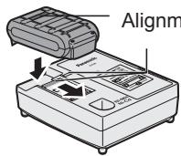
Alignment marks
- During charging, the charging lamp will be lit.
When charging is completed, an internal electronic switch will automatically be triggered to prevent overcharging.
-
Charging will not start if the battery pack is warm (for example, immediately after heavy-duty operation).
The orange standby lamp will be flashing until the battery cools down. Charging will then begin automatically. -
The charge lamp (green) will flash slowly once the battery is approximately 80% charged.
-
When charging is completed, the charging lamp will start flashing quickly in green color.
-
If the temperature of the batter pack is 0^ C or less, charging takes longer to fully charge the battery pack than the standard charging time.
Even when the battery is fully charged, it will have approximately 50% of the power of a fully charged battery at normal operating temperature.
- If the power lamp does not light immediately after the charger is plugged in, or if after the standard charging time the charging lamp does not flash quickly in green, consult an authorized dealer.
- If a fully charged battery pack is inserted into the charger again, the charging lamp lights up. After several minutes, the charging lamp may flash quickly to indicate the charging is completed.
Ni-MH/Ni-Cd Battery Pack
NOTE:
When you charge the battery pack for the first time, or after prolonged storage, charge it for about 24 hours to bring the battery up to full capacity.
Battery charger (EY0L80)
- Plug the charger into the AC outlet.
NOTE:
Sparks may be produced when the plug is inserted into the AC power supply, but this is not a problem in terms of safety.
- Insert the battery pack firmly into the charger.
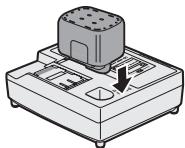
natural_image
Illustration of a mechanical device with a cylindrical component and a downward arrow indicating motion (no text or symbols)- During charging, the charging lamp will be lit.
When charging is completed, an internal electronic switch will automatically be triggered to prevent overcharging.
-
Charging will not start if the battery pack is warm (for example, immediately after heavy-duty operation).
The orange standby lamp will be flashing until the battery cools down.
Charging will then begin automatically. -
When charging is completed, the charging lamp will start flashing quickly in green color.
- If the charging lamp does not light immediately after the charger is plugged in, or if after the standard charging time the charging lamp does not flash quickly in green, consult an authorized dealer.
- If a fully charged battery pack is inserted into the charger again, the charging lamp lights up. After several minutes, the charging lamp may flash quickly to indicate the charging is completed.
LAMP INDICATIONS


Green Lit
Charger is plugged into the AC outlet.
Ready to charge.
Green Flashing Quickly
Charging is completed. (Full charge.)
Green Flashing
Battery is approximately 80% charged. (Usable charge. Li-ion only.)
Green Lit
Now charging.
Orange Lit
Battery pack is cool.
The battery pack is being charged slowly to reduce the load on the battery. (Li-ion only.)
Orange Flashing
Battery pack is warm. Charging will begin when temperature of battery pack drops.
If the temperature of the battery pack is -10^ or less, the charging status lamp (orange) will also start flashing. Charging will begin when the temperature of the battery pack goes up (L-ion only).
Charging Status Lamp
Left: green Right: orange will be displayed.
Both Orange and Green Flashing Quickly
Charging is not possible. Clogged with dust or malfunction of the battery pack.
Information on Disposal for Users of Waste Electrical & Electronic Equipment (Private Households)
natural_image
Symbol of a trash bin crossed out by two diagonal lines, representing no waste or discharge (no text or labels)
This symbol on the products and/or accompanying documents means that used electrical and electronic products should not be mixed with general household waste.
For proper treatment, recovery and recycling, please take these products to designated collection points, where they will be accepted on a free of charge basis. Alternatively, in some countries you may be able to return your products to your local retailer upon the purchase of an equivalent new product.
Disposing of this product correctly will help to save valuable
resources and prevent any potential negative effects on human health and the environment which could otherwise arise from inappropriate waste handling.
Please contact your local authority for further details of your nearest designated collection point.
Penalties may be applicable for incorrect disposal of this waste, in accordance with national legislation.
For Business Users in the European Union
If you wish to discard electrical and electronic equipment, please contact your dealer or supplier for further information.
Information on Disposal in Other Countries Outside the European Union
This symbol is only valid in the European Union.
If you wish to discard this product, please contact your local authorities or dealer and ask for the correct method of disposal.
IV. MAINTENANCE
Use only a dry, soft cloth for wiping the unit. Do not use a damp cloth, thinner, benzine, or other volatile solvents for cleaning.
V. ACCESSORIES
Use only bits suitable for size of drill's chuck.
VI. APPENDIX
MAXIMUM RECOMMENDED CAPACITIES
| Model | EY7440 | |
| Screw driving | Machine screw | M5 |
| Wood screw | 6.8 mm (17/64") | |
| Self-drilling screw | 6 mm (15/64") | |
| Drilling | For Wood | 35 mm (1-3/8") |
| For Metal | 13 mm (1/2") | |
VII. SPECIFICATIONS
MAIN UNIT
| Model | EY7440 | |
| Motor | 14.4 V DC | |
| No load speed | Low | 60 - 400 /min (rpm) |
| High | 200 - 1350 /min (rpm) | |
| Chuck capacity | ø 1.5 mm - ø 13 mm (1/16" - 1/2") | |
| Maximum torque | Low | 26 N·m (265 kgf-cm, 230 in-lbs) |
| High | 8.8 N·m (90 kgf-cm, 78 in-lbs) | |
| Clutch torque | Approx. 0.5 N·m (5 kgf-cm, 4.4 in-lbs) - 4.4 N·m (45 kgf-cm, 39 in-lbs) | |
| Overall length | 191 mm (7-1/2") | |
| Weight(with battery pack: EY9L40) | 1.6 kg (3.5 lbs) | |
BATTERY PACK
| Model | EY9L40 |
| Storage battery | Li-ion Battery |
| Battery voltage | 14.4 V DC (3.6 V × 4 cells) |
| Capacity | 3 Ah |
BATTERY CHARGER
| Model | EY0L80 |
| Electrical rating | See the rating plate on the bottom of the charger. |
| Weight | 0.95 kg (2.1 lbs) |
[Li-ion battery pack]
| Charging time | Voltage | 14.4 V |
| 3 Ah | EY9L40 | |
| Usable: 35 min. | ||
| Full: 50 min. |
[Ni-Cd/Ni-MH battery pack]
| Charging time | 7.2 V | 9.6 V | 12 V | 15.6 V | 18 V | 24 V | |
| 1.2 Ah | EY9065EY9066 | EY9080EY9086 | EY9001 | ||||
| 20 min. | |||||||
| 1.7 Ah | EY9180EY9182 | EY9101EY9103 | |||||
| 25 min. | |||||||
| 2 Ah | EY9168 | EY9188 | EY9106EY9107EY9108 | EY9136 | EY9116EY9117 | ||
| 30 min. | 60 min. | ||||||
| 3 Ah | EY9200 | EY9230 | EY9210 | ||||
| 45 min. | 90 min. | ||||||
| 3.5 Ah | EY9201 | EY9231 | EY9251 | ||||
| 55 min. | 65 min. | ||||||
NOTE: This chart may include models that are not available in your area. Please refer to the latest general catalogue.
ONLY FOR U. K.
VIII. ELECTRICAL PLUG INFORMATION
FOR YOUR SAFETY PLEASE READ THE FOLLOWING TEXT CAREFULLY
This appliance is supplied with a moulded three pin mains plug for your safety and convenience.
A 5 amp fuse is fitted in this plug.
Should the fuse need to be replaced please ensure that the replacement fuse has a rating of 5 amp and that it is approved by ASTA or BSI to BS1362.
Check for the ASTA mark 🎨 or the BSI mark 💬 on the body of the fuse.
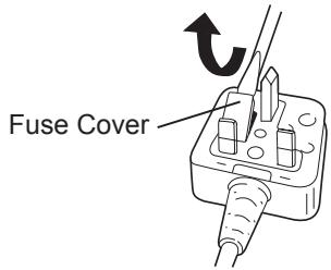
If the plug contains a removable fuse cover you must ensure that it is refitted when the fuse is replaced.
If you lose the fuse cover the plug must not be used until a replacement cover is obtained.
A replacement fuse cover can be purchased from your local Panasonic Dealer.
IF THE FITTED MOULDED PLUG IS UNSUITABLE FOR THE SOCKET OUTLET IN YOUR HOME THEN THE FUSE SHOULD BE REMOVED AND THE PLUG CUT OFF AND DISPOSED OF SAFELY.
THERE IS A DANGER OF SEVERE ELECTRICAL SHOCK IF THE CUT OFF PLUG IS INSERTED INTO ANY 13 AMP SOCKET.
If a new plug is to be fitted please observe the wiring code as shown below.
If in any doubt please consult a qualified electrician.
IMPORTANT:
The wires in this mains lead are coloured in accordance with the following code:
Blue: Neutral
Brown: Live
As the colours of the wire in the mains lead of this appliance may not correspond with the coloured markings identifying the terminals in your plug, proceed as follows.
The wire which is coloured BLUE must be connected to the terminal in the plug which is marked with the letter N or coloured BLACK.
The wire which is coloured BROWN must be connected to the terminal in the plug which is marked with the letter L or coloured RED.
Under no circumstances should either of these wires be connected to the earth terminal of the three pin plug, marked with the letter E or the Earth Symbol 12 .
How to replace the fuse: Open the fuse compartment with a screwdriver and replace the fuse and fuse cover if it is removable.
This apparatus was produced to BS800.
HINWEIS:
natural_image
Illustration of a hand using a power drill to lift a screwdriver (no text or symbols present)natural_image
Line drawing of a handheld device with a circular button and scroll, no text or symbols presentnatural_image
Illustration of a hand holding a drill pen and a handheld power supply with a rotary knob (no text or symbols)LED-PRODUKT DER KLASSE 1
natural_image
Illustration of a mechanical device with a cylindrical component and a downward arrow indicating motion (no text or symbols)natural_image
Symbol of a trash bin with crossed lines indicating no waste or restriction, accompanied by a blank rectangular block below (no text or symbols present)REMARQUE:
natural_image
Diagram of a mechanical tool with an arrow indicating rotational motion (no text or symbols)natural_image
Line drawing of a hand using a drill bit to lift a power supply (no text or symbols)natural_image
Line drawing of a mechanical device with a rotary knob and scroll wheel (no text or symbols)natural_image
Illustration of a hand holding a drill bit with a power jack and a small circular component nearby (no text or symbols)natural_image
Illustration of a mechanical device with a cylindrical component and a downward arrow indicating a force or movement (no text or symbols present)natural_image
Symbol of a trash bin crossed with no text or labels, representing waste sorting or disposal (no text present)NOTA:
natural_image
Illustration of a handheld electronic device with a battery pack and a sensor, no text or symbols presentnatural_image
Diagram of a car's internal components with an arrow indicating rotation (no text or symbols)Selezione velocità
natural_image
Line drawing of a hand using a power drill to lift a screwdriver (no text or symbols present)natural_image
Line drawing of a mechanical device with a rotary knob and scroll wheel (no text or symbols)natural_image
Illustration of a hand using a drill bit on a battery, with no visible text or symbolsnatural_image
Illustration of a mechanical device with a cylindrical component and a downward arrow indicating motion (no text or symbols)natural_image
Symbol of a waste bin with crossed lines indicating no waste, and a solid rectangle below (no text or labels)OPMERKING:
natural_image
Diagram of a mechanical component with an arrow indicating rotational motion (no text or symbols)natural_image
Illustration of a hand using a drill bit to lift a power supply (no text or symbols present)natural_image
Line drawing of a mechanical device with a rotary knob and scroll wheel (no text or symbols)natural_image
Illustration of a hand holding a drill bit next to a battery with a light bulb (no text or symbols)natural_image
Illustration of a mechanical device with a cylindrical component and a button, showing no text or symbols.natural_image
Symbol of a trash bin with crossed lines indicating no waste or restriction, and a solid rectangle below (no text or labels)NOTA:
natural_image
Diagram of a mechanical component with an arrow indicating rotational motion (no text or symbols)natural_image
Illustration of a hand using a drill bit to lift a power supply (no text or symbols visible)natural_image
Line drawing of a mechanical device with a rotary knob and scroll wheel (no text or symbols)natural_image
Illustration of a hand holding a drill bit next to a battery with a circular indicator light (no text or symbols)natural_image
Illustration of a mechanical device with a cylindrical component and a downward arrow indicating motion (no text or symbols)natural_image
Symbol of a trash bin crossed with no text or labels, representing waste sorting or disposal (no text present)BEMÆRK:
natural_image
Line drawing of a hand using a drill bit to lift a power supply (no text or symbols)natural_image
Line drawing of a mechanical device with a rotary knob and scroll wheel (no text or symbols)natural_image
Illustration of a hand holding a drill bit next to a handheld power supply with a rotary knob (no text or symbols)natural_image
Illustration of a mechanical device with a cylindrical component and a downward arrow indicating motion (no text or symbols)natural_image
Symbol of a trash bin crossed out by two diagonal lines, representing no waste or discharge (no text or labels)
OBSERVERA:
natural_image
Diagram of a mechanical component with an arrow indicating rotation or force direction (no text or symbols)Varvtalsomkoppling
natural_image
Illustration of a hand using a power drill to lift a screwdriver (no text or symbols present)natural_image
Line drawing of a mechanical device with a circular arrow indicating rotation (no text or symbols)natural_image
Illustration of a hand using a drill pen to lift a battery, with a small circular component nearby (no text or symbols)natural_image
Illustration of a mechanical device with a cylindrical component and a downward arrow indicating motion (no text or symbols)natural_image
Symbol of a trash bin with crossed lines indicating no waste or restriction, and a solid black rectangle below (no text or labels)MERK:
Montere eller demontere batteripakken
natural_image
Diagram of a mechanical tool with an arrow indicating rotation or movement (no text or symbols present)Valg av hastighet
natural_image
Illustration of a hand using a power drill to lift a screwdriver (no text or symbols present)natural_image
Line drawing of a mechanical device with a circular arrow indicating rotation (no text or symbols)natural_image
Illustration of a hand holding a drill pen and a handheld power supply with a circular button (no text or symbols)(2) Varsellampe for overoppheting

Av
(normalt arbeid)

natural_image
Illustration of a mechanical device with a cylindrical component and a downward arrow indicating motion (no text or symbols)- Under lading lyser ladelampen hele
tiden.
natural_image
Symbol of a trash bin crossed out by two diagonal lines, representing no waste or discharge (no text or labels)
HUOMAUTUS:
natural_image
Illustration of a hand using a power drill to lift a screwdriver (no text or symbols present)Vyölenkin käyttö
⚠️ VAROITUS!
natural_image
Line drawing of a mechanical device with a rotary knob and scroll wheel (no text or symbols)natural_image
Illustration of a hand holding a drill bit next to a battery with a screwdriver (no text or symbols)natural_image
Illustration of a mechanical device with a cylindrical component and a downward arrow indicating motion (no text or symbols)natural_image
Symbol of a trash bin crossed with no text or labels, indicating no waste or disposal (no text present)ПРИМЕЧАНИЕ:
natural_image
Diagram of a mechanical component with an arrow indicating rotational motion (no text or symbols)Выбор скорости
natural_image
Line drawing of a hand using a drill bit to lift a power supply (no text or symbols)natural_image
Line drawing of a mechanical device with a scroll wheel and adjustment knob (no text or symbols)natural_image
Illustration of a hand holding a drill pen and a battery with a circular indicator light (no text or symbols)natural_image
Illustration of a mechanical device with a cylindrical component and a downward arrow indicating motion (no text or symbols)natural_image
Symbol of a trash bin crossed out by two diagonal lines (no text or numbers present)ПРИМІТКА:
natural_image
Diagram of a mechanical tool with an arrow indicating rotational motion (no text or symbols)Вибір швидкості
natural_image
Line drawing of a hand using a drill bit to lift a power supply (no text or symbols)natural_image
Line drawing of a robotic vacuum cleaner with a rotary knob (no text or symbols)natural_image
Illustration of a hand holding a drill bit with a power jack and a small circular button nearby (no text or symbols)natural_image
Illustration of a mechanical device with a cylindrical component and a downward arrow indicating motion (no text or symbols)natural_image
Symbol of a trash bin crossed out by two diagonal lines, representing no waste or discharge (no text or labels)Matsushita Electric Works, Ltd.
Osaka, Japan