Chill CP12G10B - Air-conditioner Friedrich - Free user manual and instructions
Find the device manual for free Chill CP12G10B Friedrich in PDF.

| Product Type | Portable Air Conditioner |
| Brand | Friedrich |
| Model | Chill CP12G10B |
| Cooling Capacity | 12,000 BTU/h |
| Heating Capacity | 12,000 BTU/h (3.5 kW) |
| Coverage Area | Approximately 30 m² |
| Dimensions (W x D x H) | 76 x 46 x 43 cm |
| Weight | 32 kg |
| Power Supply | 220-240 V, 50 Hz |
| Power Consumption (cooling) | 1,200 W |
| Energy Efficiency Ratio (EER) | 12.1 |
| Noise Level (max) | 56 dB |
| Refrigerant | R410A |
| Operating Modes | Cooling, heating, ventilation, dehumidification |
| Functions | Timer, remote control, oscillation, auto-restart |
| Filter | Washable, activated carbon |
| Maintenance | Clean filter every 2 weeks |
| Safety | Automatic shut-off in case of overheating |
| Warranty | 1 year |
Frequently Asked Questions - Chill CP12G10B Friedrich
User questions about Chill CP12G10B Friedrich
0 question about this device. Answer the ones you know or ask your own.
Ask a new question about this device
Download the instructions for your Air-conditioner in PDF format for free! Find your manual Chill CP12G10B - Friedrich and take your electronic device back in hand. On this page are published all the documents necessary for the use of your device. Chill CP12G10B by Friedrich.
USER MANUAL Chill CP12G10B Friedrich
Room Air Conditioner Installation and Operation Manual
natural_image
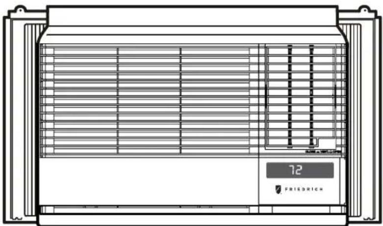
Technical line drawing of a front-mounted HVAC unit with ventilation grilles and a digital display showing 'FRIEDRICH' (no text or symbols on the diagram itself)Chill
230 Volts
115 Volts
- CP18
- CP15
- CP24
Registering Your Room Air Conditioner
Model information can be found on the name plate located on the side of the unit near the control panel. Please complete and mail the owner registration card furnished with this product or register on-line at www.friedrich.com (USA only). For your future convenience, record the model information here.
MODEL NUMBER
SERIAL NUMBER
PURCHASE DATE
natural_image
Line drawing of a refrigerator with ventilation grilles and a digital display showing '72' (no text or symbols on the main diagram)Congratulations! Thank you for choosing Friedrich.
Your Friedrich unit is designed for maximum comfort and quietness.
Table of Contents
Introduction ......2
Safety Precautions....3
How to operate your Friedrich ....5
Adjusting the Air Flow Direction....6
Care and Maintenance ....7
Hardware Location 8
Installation Instructions....9
Troubleshooting Tips....16
Warranty 17
Satefy....18
Before Operating Your Unit
Make sure the wiring is adequate for your unit.
If you have fuses, they should be of the time delay type. Before you install or relocate this unit, be sure that the amperage rating of the circuit breaker or time delay fuse does not exceed the amp rating listed in figure 1.
DO NOT use an extension cord.
The cord provided will carry the proper amount of electrical power to the unit; an extension cord will not.
Make sure that the receptacle is compatible with the wall plug provided.
This insures proper grounding. If you have a two-prong receptacle you will need to have the circuit replaced by a certified electrician with a grounded circuit that meets all national and local codes and ordinances. You must use the three-prong plug furnished with the air conditioner.
| 115V~ | 230V~ | Power cord may include a current interrupter device. A test and reset button is provided on the plug case. The device should be tested on a periodic basis by first pressing the TEST button and then the RESET button. If the TEST button does not trip or if the RESET button will not stay engaged, discontinue use of the air conditioner and contact a qualified service technician. | |||
 | 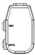 |  |  |  | |
NOTE!
Aluminum house wiring may pose special problems. Consult a qualified electrician.
For the Best Cooling Performance and Energy Efficiency
Keep the filter clean
Make sure that your air conditioner is always in top performing condition by cleaning the filter regularly. Instructions for removing and cleaning the filter can be found on page 7.
Provide good air flow
Make sure that the airflow to and from the unit is clear. Your air conditioner puts the air out at the side of the unit, and takes in air at the left. Airflow is critical for good operation. It is just as important on the outside of the building that the airflow around the unit exterior is not blocked.
Unit Placement
If your air conditioner can be placed in a window or a wall that is shaded by a tree or another building, the unit will operate even more efficiently. Using drapes or blinds on the sunny side of the dwelling will also add to your unit's efficiency.
Insulation
Good insulation will be a big help in maintaining desirable comfort levels. Doors should have weather stripping. Be sure to caulk around doors and windows.
To prevent injury and property damage, follow these instructions.
■ Incorrect operation due to ignoring instructions can cause harm or damage. The seriousness is classified by the following indications.

WARNING
This symbol indicates the possibility of death or serious injury.

CAUTION
This symbol indicates the possibility of injury or damage to properties only.
■ Meanings of symbols used in this manual are as shown below.
 | Never Do This | ||
 |  |  | Always Do This |

WARNING
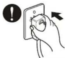
Plug in the power plug properly.
- Otherwise, it will cause electric shock or fire due to heat generation.
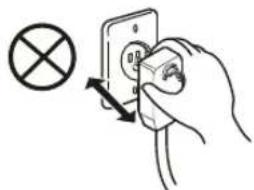
Do not operate or stop the unit by inserting or pulling out the power plug.
- It will cause electric shock or fire due to heat generation.
natural_image
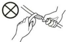
Hand inserting a socket into an electrical outlet with a cross symbol (no text or labels)Do not damage or use an unspecified power cord.
- It will cause electric shock or fire. - If the power cord is damaged, it must be replaced by the manufacturer or a Friedrich-certified service agent.
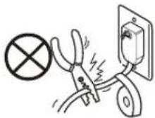
Do not modify power cord length.
- It will cause electric shock or fire due to heat generation.
natural_image
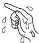
Illustration of hands holding a tool with a cross symbol (no text or labels)Do not operate with wet hands or in damp environment.
• It will cause electric shock.

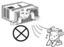
Do not direct air flow directly at room occupants.
• This could lead to health problems.
For inner cleaning, contact an Authorized Service Center or a dealer. Do not use harsh detergent that causes corrosion or damage on the unit.
- Harsh detergent may also cause failure of product, fire, or electronic shock.

CAUTION
When the air filter is to be removed, do not touch the metal parts of the unit.
• They are sharp and may cause an injury.
natural_image
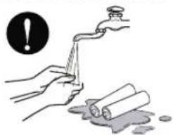
Illustration of a person reacting to a device with an 'X' symbol (no text or labels present)Do not clean the air conditioner with water.
• Water may enter the unit and degrade the insulation. It may cause an electric shock.
When the unit is to be cleaned, switch the unit off, and unplug it.
- Since the fan rotates at high speed during operation, it may cause an injury.
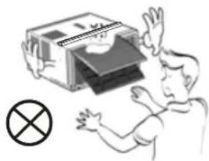
Do not operate the unit without the air filter or when the front intake grille has been removed.
- It could cause dust to accumulate on the heat exchanger.
natural_image
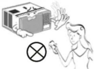
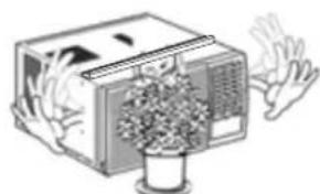
Illustration of a person holding up a stack of books with a cross symbol below (no text or symbols present)Do not put a pet or house plant where it will be exposed to direct air flow.
• This could injure the pets or plants.
natural_image
Illustration of a vintage air conditioner unit with hands reaching out, emitting steam (no text or symbols)
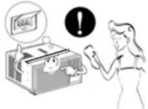
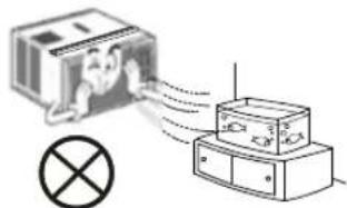
Do not use for special purposes.
- Do not use this air conditioner to preserve precision devices, food, pets, plants, and art objects. It may cause deterioration of quality, etc.
natural_image
Diagram showing a device emitting signal waves into a box, with a light bulb symbol nearby (no text or labels)Do not operate switches with wet hands.
- It may cause an electric shock.
natural_image
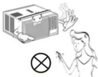
Illustration of a person reacting to a device with a cross symbol (no text or labels)Do not apply an insecticide or flammable spray.
- It may cause a fire or deformation of the cabinet.
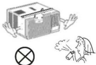
natural_image
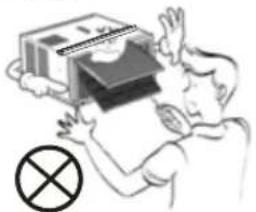
Illustration of a box with a warning symbol and a person emitting smoke (no text or symbols present)SHARP EDGES!
The edges of the case can be SHARP!
- Use caution when handling the case. Grip it firmly and do not allow it to slip while holding it.
- Use heavy gloves to handle the case if necessary.
• DO NOT allow the case to slide against your skin!
Sharp edges
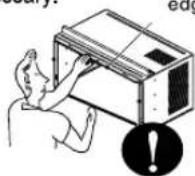
If the liquid from the batteries gets onto your skin or clothes, wash it well with clean water. Do not use the remote if the batteries have leaked.
• The chemicals in batteries could cause burns or other health hazards.
natural_image
Illustration of hands using a tool to clean or wash material, with a warning symbol above (no text or symbols present)If you eat the liquid from the batteries, brush your teeth and see doctor.Do not use the remote if the batteries have leaked.
• The chemicals in batteries could cause burns or other health hazards.

flowchart
graph TD
    A["⑥"] --> B["Mode"]
    B --> C["Fan"]
    B --> D["Cool"]
    B --> E["Dry"]
    B --> F["Money Saver®"]
    C --> G["Timer On/Off"]
    G --> H["Check Filter"]
    H --> I["F hr"]
    J["⑧"] --> K["Fan Speed"]
    K --> L["Filter Reset"]
    L --> M["Temp"]
    M --> N["Auto Swing"]
    M --> O["Power"]
    P["⑤"] --> Q["④"]
    Q --> R["③"]
    R --> S["②"]
    S --> T["①"]
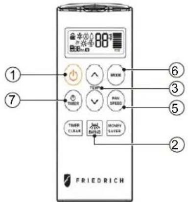
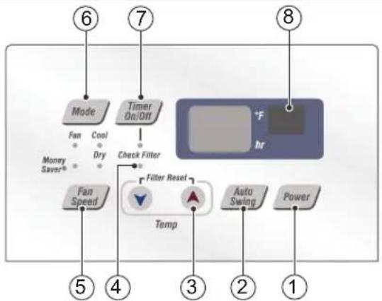
Control and Remote Control Operations
1. POWER
Operation begins when this button is pressed and stops when you press the button again.
2. AUTO SWING
This button can automatically control the air flow direction.
3. TEMPERATURE CONTROL
The thermostat monitors room temperature to maintain the desired temperature. The thermostat can be set between 60^ F\~ 86^ F ( 16^ C\~ 30^ C).
4. CHECK FILTER & FILTER RESET
Check Filter: Your 'Check Filter' LED will light up after approximately 250 hours of operation, notifying you that your filter needs to be cleaned.
Filter Reset: press 'Temp ∨ ∧' together to turn off 'Check Filter' light.
*Filter Reset must be done from unit control panel, not remote control
5. FAN SPEED SELECTOR
For increased power while cooling, select a higher fan speed.
3 speeds: Low; Med; High
6. OPERATION MODE SELECTOR
Push the 'Mode' button to rotate between MoneySaver → Cool → Fan → Dry modes. (select Dry mode for dry/dehumidifier operation)
MoneySaver: The fan will stop when the compressor stops cooling. The fan will turn on approximately every 3 minutes to sample to room air and determine if more cooling is needed.
Cool: fan runs continually for normal cooling operation
Fan Only: Fan-only operation
*MoneySaver has it's own button on your remote control
7. ON/OFF TIMER
ON: If the unit is off, use Timer to set number of hours before unit starts.
- Push Timer button to advance setting from 1hr
- 2hrs - ...24hrs maximum.
OFF: You will usually use shut-off time while you sleep.
- If unit is running, use Timer to set number of hours until shut-off.
- Push Timer button to advance setting from 1hr 2hrs....24hrs maximum.
*Timer Clear: On remote control, 'Timer Clear' button will cancel the timer setting
8. REMOTE CONTROL SENSOR
To receive the signal from remote controller.
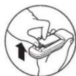
Inserting the Remote Control Batteries
-
Push out the cover on the back of the remote control with your thumb
-
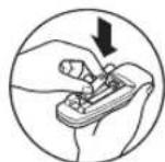
Pay attention to polarity and insert two new AAA 1.5V batteries.
-
Reattach the cover.
NOTE: Do not use rechargeable batteries. Make sure that both batteries are new.
- In order to prevent discharge, remove the batteries from the remote control if the air conditioner is not going to be used for an extended period of time
Keep the remote control away from extremely hot or humid places.
To maintain optimal operation of the remote control, the remote sensor should not be exposed to direct sunlight.
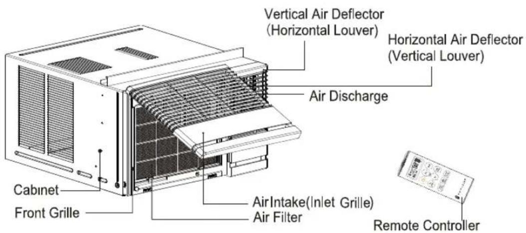
Adjusting the Air Flow Direction
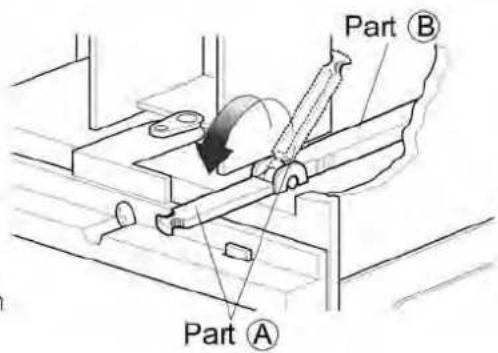
Vent Control
For maximum cooling efficiency, CLOSE the vent. This will allow internal air circulation. OPEN the vent to discharge stale air.
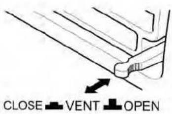
NOTE: Before using the ventilation feature, position the lever, as shown. First, pull down part A to horizontal line with part B
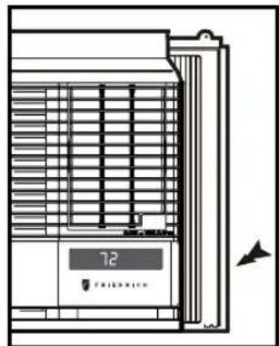
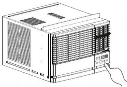
Adjusting the Air Flow Direction
Airflow can be adjusted by changing the direction of the air conditioner's louvers.
• Adjusting Horizontal Air Flow Direction
Adjusting the vertical louvers left and right will change horizontal airflow.
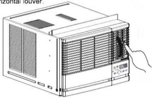
• Adjusting Vertical Air Flow Direction
Adjusting the horizontal louver up and down will change vertical airflow. The louver can be adjusted by pressing in at the top or button of the horizontal louver.
natural_image
Line drawing of a computer HVAC unit with ventilation grilles and a digital display panel, no text or symbols presentAdjusting horizontal air flow
natural_image
Line drawing of an air conditioner unit with a hand pointing to the front panel (no text or symbols present)Adjusting vertical air flow
Turn the power off and unplug the power plug before cleaning the air conditioner.
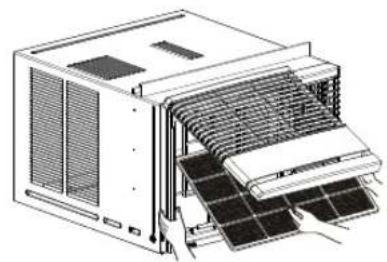
Air Filter
The air filter behind the inlet grille should be checked and cleaned at least once every 2 weeks (or as necessary) to maintain optimal performance of the air conditioner.
How to remove the air filter
- Open the inlet grille upward by pulling out the bottom of the inlet grille.(a)
- Remove the air filter from the front grille assembly by pulling the air filter up slightly.
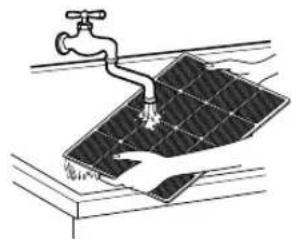
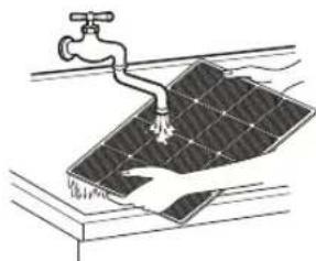
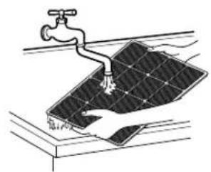
- Wash the filter using lukewarm water below 104°F(40°C).(b)
- Gently shake the excess water from the filter. When completely dry, replace the filter.
natural_image
Technical line drawing of an internal air conditioner unit with cooling fins and ventilation grilles (no text or labels)(a)
natural_image
Illustration of a faucet spraying water onto a solar panel (no text or symbols)(b)
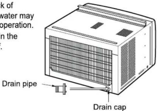
Drainage
The base pan may overflow due to high humidity. To drain the excess water, remove the drain cap from the back of the unit and secure the drainpipe. However, excess water may drip out of the back of the basepan, which is normal operation. When pressing the drainpipe into place, apply force in the direction away from the fins to avoid injuring yourself.
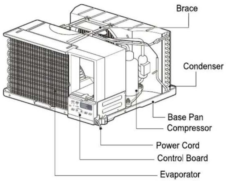
Product Features

CAUTION
This appliance should be installed in accordance with local and national wiring regulations. This manual acts as a guide to help to explain product features.
Read these instructions completely and carefully.
Tools You Will Need
☐ Phillips-head screwdriver
□ Flat-blade screwdriver
☐ Ruler or tape measure
□ Scissors or knife
□ Pencil
□ Level
□ Hammer
Before You Begin
NOTE TO INSTALLER: Leave these instructions with the air conditioner after installation is complete.
NOTE TO CONSUMER: Keep this Installation and Operation Manual for future use.
Important notes:
It is recommended that proper attire be worn during installation.
For personal safety, this air conditioner must be properly grounded.
It is important to have the wall outlet and circuit checked by a qualified electrician if there is any doubt as to whether a proper ground exists.
CAUTION:
Do not under any circumstances, cut or remove the third (ground) prong from the power cord.
Do not change the plug on the power cord of this air conditioner.
Aluminum house wiring may present special problems; consult a qualified electrician.
How to Install the Unit
- To prevent vibration and excess noise, make sure the unit is installed securely and firmly
- Install the unit where the sunlight does not shine directly on the unit.
- The outside of the cabinet must outward for at least 12" and there should be no obstacles, such as a fence or wall, within 20" from the back of the cabinet, as it will prevent heat radiation of the condenser.
Restriction of outside air will greatly reduce the cooling efficiency of the air conditioner.
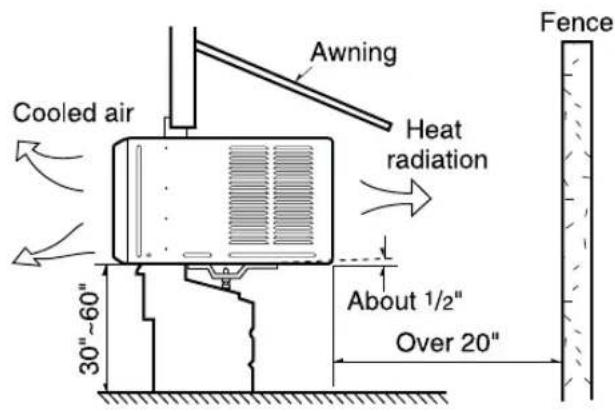
CAUTION: DO NOT cover or block any of the side louvers. All side louvers of the cabinet must remain exposed and unobstructed to the outside of the structure.
- Install the unit with a rear, downward slope, so the back is slightly lower than the front (about 1/4" bubble on a level). This will force condensation to flow to the outside.
- Install the unit with the bottom about 30"-60" above the floor level.
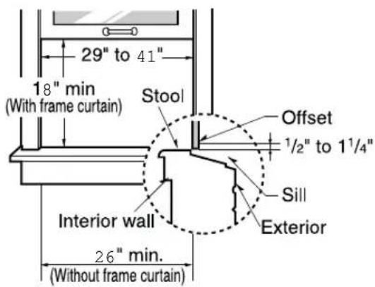
Window Requirements
NOTE: All supporting parts should be secured to firm wood, masonry, or metal.
- This unit is designed for installation in standard double hung windows with actual opening widths from 29" to 41".
- The top and bottom window sash must open sufficiently to allow a clear vertical opening of 18" from the bottom of the upper sash to the window stool.
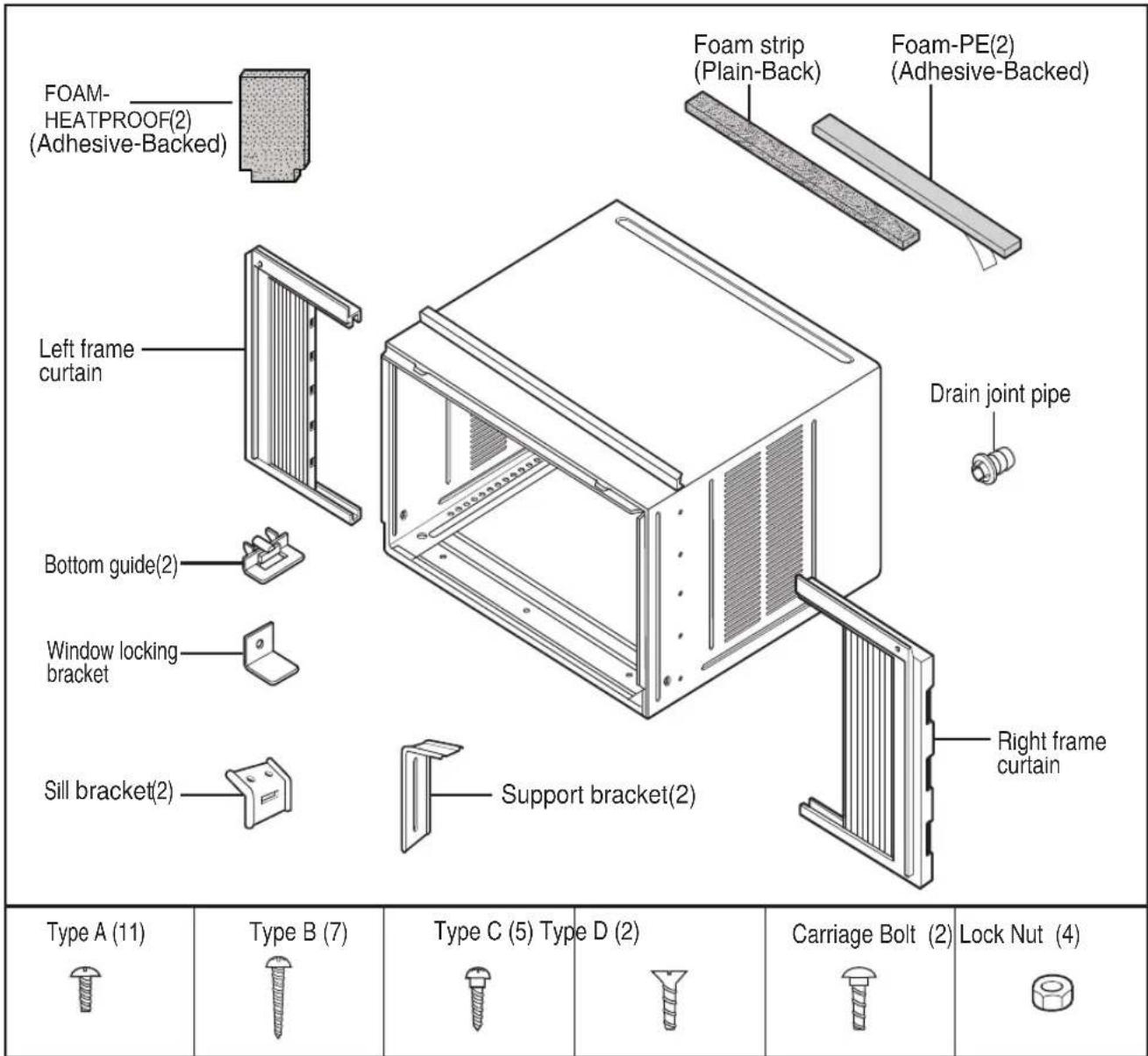
Installation Kit Contents
Have the following tools available for installation:
* Screwdriver (Slotted and Phillips)
* Knife
* Pencil
* Ruler
* Hammer
* Level
Suggested Tool Requirements
SCREWDRIVER(+,-), RULER, KNIFE, HAMMER, PENCIL, LEVEL
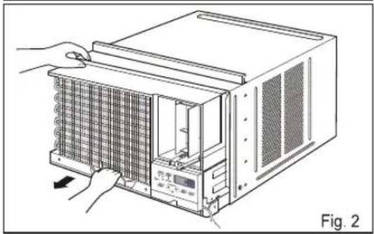
PREPARATION OF CHASSIS
- Remove the screws which fasten the cabinet at both sides and at the back. (Fig.1)
- Slide the unit out from the cabinet by gripping the base pan handle and pulling forward while bracing the cabinet. (Fig.2)
- Cut the window sash seal to the proper length. Peel off the backing and attach the Foam-PE to the underside of the window sash and bottom of window frame. (Fig.3)
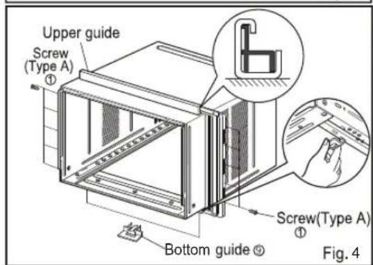
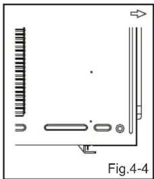
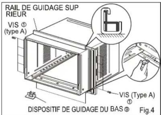
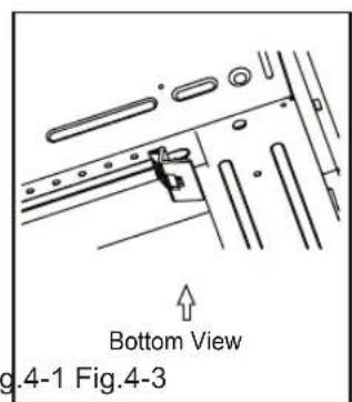
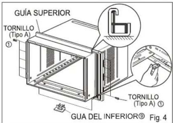
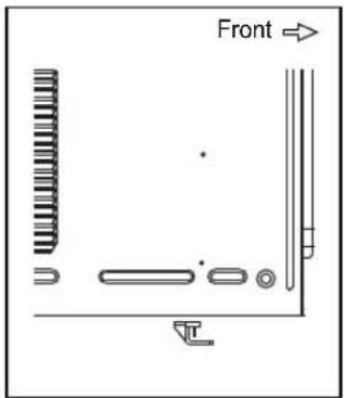
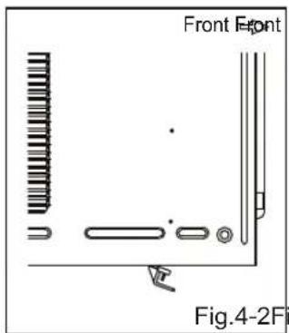
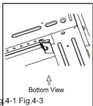
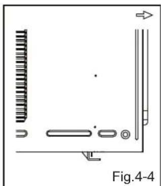
- Insert the Bottom guides into the bottom of the cabinet. (Fig.4)
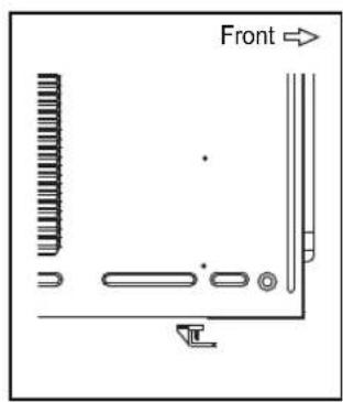
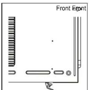
4a. Make sure the pins on the bottom frame guide are facing the back of the unit.(Fig.4-1)
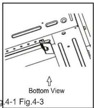
4b. Align both pins to the slotted areas under the cabinet.(Fig.4-2, Fig.4-3)
4c. Push upward fully to insert pins into slotted areas and secure frame guide.(Fig.4-4)
- Insert the Frame Curtain into the Upper Guide and Frame Guides.(Fig.4)
- Fasten the curtains to the unit with 10 Type A screws. (Fig.4)

natural_image
Illustration of a computer rack unit with hands operating it, showing internal components and ventilation slots (no text or symbols)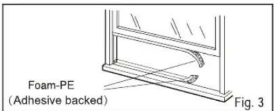

natural_image
Pure technical diagram showing mechanical components without any text, numbers, or symbolsCabinet Installation
- Open the window. Mark a line on the center of the window stool between the side window stop moldings.
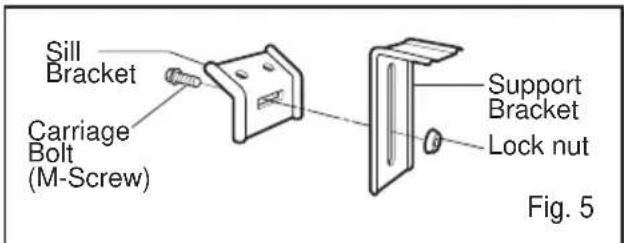
Loosely attach the sill bracket to the support bracket using the carriage bolt and the lock nut.
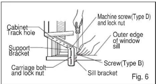
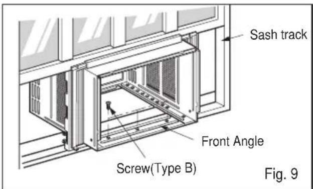
- Attach the sill bracket to the window sill using the screws (Type B).
Carefully place the cabinet on the window stool and align the center mark on the bottom front with the center line marked window stool.
- Using the M-screw and the lock nut, attach the support bracket to the cabinet track hole. Use the first track hole after the sill bracket on the outer edge of the window sill. Tighten the carriage bolt and the lock nut. Be sure the cabinet slants outward.
CAUTION
Do not drill a hole in the bottom pan. The unit is designed to operate with approximately 1/2" of water in bottom pan.
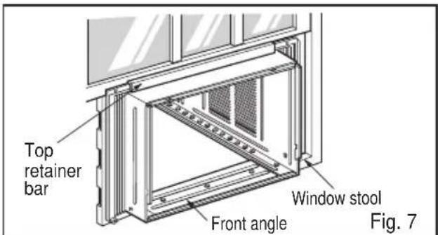
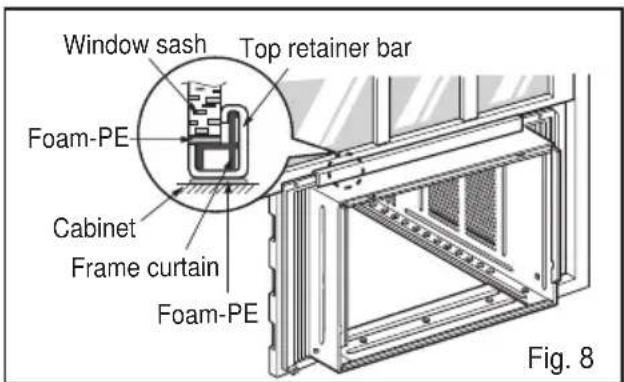
- Pull the bottom window sash down behind the Top retainer bar until they meet.
NOTICE
-
Do not pull the window sash down so tightly that the movement of Frame curtain is restricted. Attach the cabinet to the window stool by driving the screws (Type B) through the cabinet into window stool.
-
The cabinet should be installed with a very slight tilt downward toward the outside.
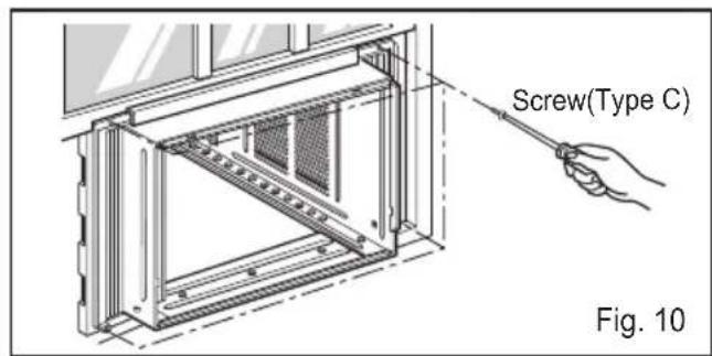
- Pull each Frame curtain fully to each window sash track, and pull the bottom window sash down behind the Top retainer bar until it meets.
- Attach each Frame curtain the window sash by using screws (Type C.) (See Fig. 10)
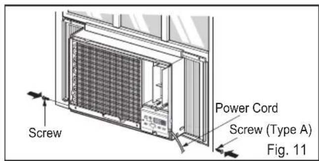
- Slide the unit into the cabinet.(See Fig. 11)
CAUTION
For security purpose, reinstall screws(Type A) at cabinet's sides.
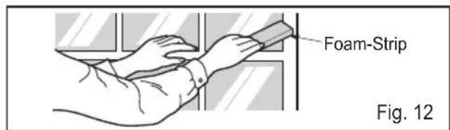
- Cut the Foam-strip to the proper length and insert between the upper window sash and the lower window sash.(See Fig. 12)
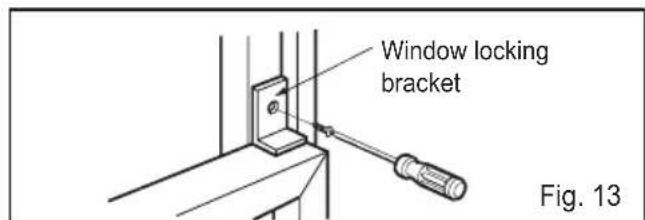
- Attach the Window locking bracket with a screw (Type C.) (See Fig. 13)
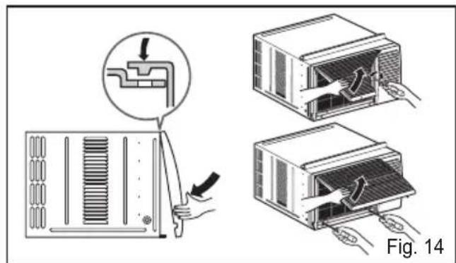
- Attach the front grille to the cabinet by inserting the tabs on the grille into the tabs on the front of the cabinet. Push the grille in until it snaps into place.(See Fig.14)
- Lift the inlet grille and secure it with a screw (Type A) through the front grille.(See Fig. 14)
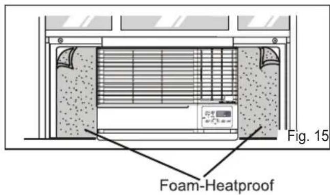
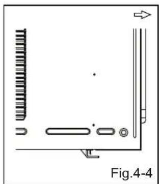
- Cut the adhesive-backed Foam-Heatproofs to the Guide Panel size.
Remove the backing from the Foam-Heatproofs and attach the Foam-Heatproofs to Guide Panel.(See Fig. 15)
Tip!
Foam-Heatproof improves the cooling capability of the unit.
- Window installation of room air conditioner is now completed. See ELECTRICAL DATA for attaching power cord to electrical outlet.
Through-the-Wall Installation Instructions-Optional
The case may be installed through-the-wall in both existing and new construction.
Read completely, then follow step-by-step.
NOTE: Obtain all materials locally for mounting the air conditioner through-the-wall.
① IMPORTANT (cont.)
D Secure with 14 wood screws anchored at least an inch into the wall support structure.
NOTE: Drill pilot holes, if necessary, for proper installation. If the frame is oversized, use shims to prevent case distortion.
① IMPORTANT
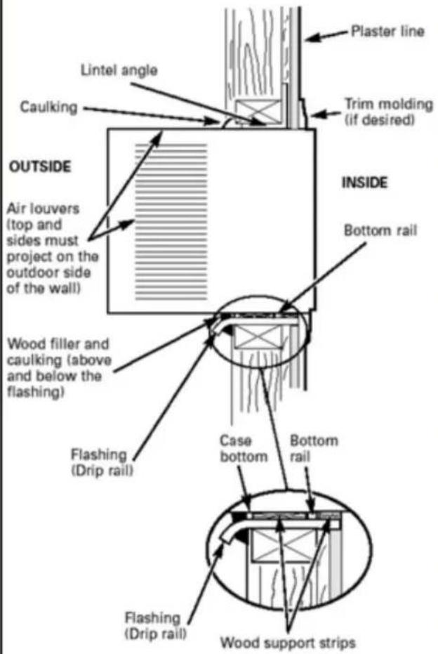
Through-the-wall installation is not appropriate if any of the side or top louvers in the case will be obstructed by the wall.
All side and top louvers in the case must project on the outdoor side of the wall.
The room side of the case must project into the room far enough to maximize the balance of the unit.
The case must be installed level from side-to side and with a slight tilt from front to rear. Use a level; no more than a 1/2 bubble will be the correct case slant to the outside.
Lintel angle is required to support bricks or blocks above opening.
Flashing is required and should extend the length of the opening to ensure no inside cavity leakage occurs.
A Remove the air conditioner from the case. For specific instruction, refer to the Window Installation Instructions.
B Make certain that a wall receptacle is available close to the hole location or make arrangementsto install a receptacle.
natural_image
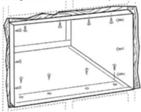
Technical line drawing of a rectangular enclosure with internal compartments and mounting holes (no text or symbols)C Place the case in the wall opening and place wood support strips between the case bottom and the flashing on both sides of the bottom rail. They should be the same height as the bottom rail and the same length as the wall opening.
② FINISH THE WALL OPENING
A Caulk all four sides on the outdoor side of the case to prevent moisture from getting through to the interior wall. Use of flashing (drip rail) will further prevent water from dripping inside the wall and down the outside of the building.
B Place the air conditioner into the case. For specific instruction, refer to the Window Installation Instructions.
Troubleshooting Tips save time and money! Review the chart below first and you may not need to call for service.
Normal Operation
- You may hear a pinging noise caused by water being picked up and thrown against the condenser on rainy days or when the humidity is high. This design feature helps remove moisture and improve efficiency.
- You may hear the thermostat click when the compressor cycles on and off.
- Water will collect in the base pan during high humidity or on rainy days. The water may overflow and drip from the outdoor side of the unit.
- The fan may run even when the compressor does not.
- Your air conditioner is designed to cool in warm weather when the outside temperature is above 60^(16^) and below 109^(43^) .
Abnormal Operation
| Problem | Possible Causes | What To Do |
| Air conditioner does not start | ■ The air conditioner is unplugged. | · Make sure the air conditioner plug is pushed completely into the outlet. |
| ■ The fuse is blown/circuit breaker is tripped. | · Check the house fuse/circuit breaker box and replace the fuse or reset the breaker. | |
| ■ Power failure. | · If power failure occurs, turn the mode control to Off. When power is restored, wait 3 minutes to restart the air conditioner to prevent tripping of the compressor overload. | |
| ■ The current interrupter device was tripped on the power cord. | · Press the RESET button located on the power cord plug. If the RESET button will not stay engaged, discontinue use of the air conditioner and contact a qualified service technician. | |
| Air conditioner does not cool as it should | ■ Airflow is restricted. | · Make sure there are no curtains, blinds, or furniture blocking the front of the air conditioner. |
| ■ The THERMOSTAT may not be set high enough. | · Push temperature setting button to coolest temperature setting of 60°F. | |
| ■ The air filter is dirty. | · Clean the filter at least every 2 weeks. See the operating instructions section. | |
| ■ The room may have been hot. | · When the air conditioner is first turned on you need to allow time for the room to cool down. | |
| ■ Cold air is escaping. | · Check for open furnace floor registers and cold air returns. · Set the air conditioner's vent to the closed position. | |
| ■ Cooling coils have iced up. | · See Air Conditioner Freezing Up below. | |
| Air conditioner freezing up | ■ Ice blocks the air flow and stops the air conditioner from cooling the room. | · Set the mode control on high fan until the ice thaws out. This may indicate a bigger problem. |
FRIEDRICH
Friedrich Air Conditioning Company
10001 Reunion Place, Suite 500
San Antonio, TX 78216
800.541.6645
www.friedrich.com
ROOM AIR CONDITIONERS LIMITED WARRANTY
FIRST YEAR
ANY PART: If any part supplied by FRIEDRICH fails because of a defect in workmanship or material within twelve months from date of original purchase, FRIEDRICH will repair the product at no charge, provided room air conditioner is reasonably accessible for service. Any additional labor cost for removing inaccessible units and/or charges for mileage related to travel by a Service Agency that exceeds 25 miles one way will be the responsibility of the owner. This remedy is expressly agreed to be the exclusive remedy within twelve months from the date of the original purchase.
SECOND THROUGH FIFTH YEAR
SEALED REFRIGERANT SYSTEM: If the Sealed Refrigeration System (defined for this purpose as the compressor, condenser coil, evaporator coil, reversing valve, check valve, capillary, filter drier, and all interconnecting tubing) supplied by FRIEDRICH in your Room Air Conditioner fails because of a defect in workmanship or material within sixty months from date of purchase, FRIEDRICH will pay a labor allowance and parts necessary to repair the Sealed Refrigeration System; PROVIDED FRIEDRICH will not pay the cost of diagnosis of the problem, removal, freight charges, and transportation of the air conditioner to and from the Service Agency, and the reinstallation charges associated with repair of the Sealed Refrigeration System. All such cost will be the sole responsibility of the owner. This remedy is expressly agreed to be the exclusive remedy within sixty months from the date of the original purchase.
APPLICABILITY AND LIMITATIONS: This warranty is applicable only to units retained within the Fifty States of the U.S.A., District of Columbia, and Canada. This warranty is not applicable to:
- Air filters, fuses, batteries and the front grille removal tool.
-
Products on which the model and serial numbers have been removed.
-
Products which have defects or damage which results from improper installation, wiring, electrical current characteristics, or maintenance; or caused by accident, misuse or abuse, fire, flood, alterations and/or misapplication of the product and/or units installed in a corrosive atmosphere, default or delay in performance caused by war, government restrictions or restraints, strikes, material shortages beyond the control of FRIEDRICH, or acts of God.
OBTAINING WA RRANTY PERFORMA NCE: Service will be provided by the FRIEDRICH A authorized Dealer or Serv ice Organization in your area. They are listed in the Yellow Pages. If assistance is required in obtaining warranty performance, write to: Friedrich Air Conditioning Co., ATTN: Warranty Registration, 10001 Reunion Place, Ste. 500, San Antonio, TX 78216.
LIMITATIONS: THIS WARRANTY IS GIVEN IN LIEU OF A LL OTHER W ARRANTIES. A nything in the w arranty notwithstanding, ANY IMPLIED WA RRANTIES OF FITNESS FOR PARTICULAR PURPOSE A ND/OR MERCHA NTABILITY SHALL BE LIMITED TO THE DURATION OF THIS EXPRESS WARRANTY. MANUFACTURER EXPRESSLY DISCLAIMS AND EXCLUDES ANY LIABILITY FOR CONSEQUENTIAL OR INCIDENTAL DAMAGE FOR BREACH OF ANY EXPRESSED OR IMPLIED WARRANTY.
Performance of Friedrich's Warranty obligation is limited to one of the following methods:
- Repair of the unit
- A refund to the customer for the prorated value of the unit based upon the remaining warranty period of the unit.
- Providing a replacement unit of equal value
The method of fulfillment of the warranty obligation is at the sole discretion of Friedrich Air Conditioning.
NOTE: Some states do not allow limitations on how long an implied warranty lasts, or do not allow the limitation or exclusion of consequential or incidental damages, so the foregoing exclusions and limitations may not apply to you.
OTHER: This warranty gives you specific legal rights, and you may also have other rights which vary from state to state.
PROOF OF PURCHASE: Owner must provide proof of purchase in order to receive any warranty related services.
All service calls for explaining the operation of this product will be the sole responsibility of the consumer.
All warranty service must be provided by an Authorized FRIEDRICH Service Agency, unless authorized by FRIEDRICH prior to repairs being made.
(11-10)
WARNING
- Do not use means to accelerate the defrosting process or to clean, other than those recommended by the manufacturer.
- The appliance shall be stored in a room without continuously operating ignition sources (for example: open flames, an operating gas appliance or an operating electric heater).
- Do not pierce or burn. Be aware that refrigerants may not contain an odor.
CAUTION
This unit contains flammable refrigerant and has special safety precautions not normally associated with older units. Please follow all precautions and advisories.
- Use caution while handling and prevent damage to unit. Do not put any holes into product for any reason, this can cause damage to product and prevent unit from cooling.
- Maintenance and cleaning of unit should be performed by trained personnel. Failure to properly clean unit can result in damage to the refrigeration system and or the electrical system.
- Make certain that all the air circulation/ventilation openings are free from obstruction.
- Service should only be performed by technicains properly trained and certified in the use of flammable refrigerants. Any service performed by unauthorized servicers/individuals will void all warranties.
- When storing the appliance, do not put in a room with any open flame appliances, such as gas water heaters or furnaces. Also keep away from electric heaters. Damaged units should be repaired before storage.
FRIEDRICH
natural_image
Technical line drawing of a refrigerated air vent system with ventilation grilles and a digital display (no text or symbols)Chill
230 Volts
115 Volts
- CP18
- CP15
- CP24
natural_image
Technical line drawing of a refrigerant unit with ventilation grilles and a digital display (no text or symbols)Félicitations!
natural_image
Hand inserting a plug into an electrical socket with a cross symbol (no text or labels)natural_image
Illustration of hands holding a tool with a cross symbol nearby (no text or labels)natural_image
Illustration of a cartoon character reacting with a crossed-out circle and a falling figure (no text or symbols)natural_image
Illustration of a person reacting to a printer with an open circuit symbol (no text or labels present)natural_image
Illustration of a person using a handheld device to interact with a box, with a crossed-out symbol nearby (no text or labels)natural_image
Illustration of a person holding up a large box with a checkmark symbol (no text or symbols present)natural_image
Illustration of a portable air conditioner unit with a potted plant and a prohibition symbol (no text or labels)natural_image
Illustration of a person reacting to a device with a hand gesture, accompanied by a crossed-out prohibition symbol (no text or labels)natural_image
Illustration of a box with a face and a prohibition symbol, accompanied by a person holding a spray bottle (no text or symbols present)natural_image
Line drawing of an air conditioner unit with a hand pointing to its control panel (no text or symbols present)natural_image
Line drawing of a computer HVAC unit with ventilation grilles and a hand pointing to the side panel (no text or symbols)natural_image
Technical line drawing of a server rack unit with cooling fins and ventilation grilles (no text or symbols)(a)
natural_image
Illustration of a faucet spraying water onto a solar panel (no text or symbols)(b)
Drainage
natural_image
Illustration of a computer rack unit with hands operating it, showing internal components and ventilation slots (no text or symbols)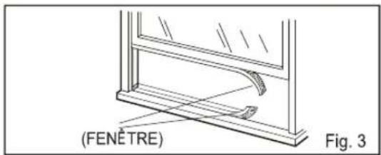

natural_image
Technical diagram showing mechanical components and directional arrows, labeled Fig.4-4 (no text or symbols on diagram itself)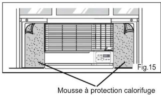
natural_image
Technical line drawing of a rectangular enclosure with internal compartments and mounting holes (no text or symbols)Friedrich Air Conditioning Company
10001 Reunion Place, Suite 500
San Antonio, Tx 78216
800.541.6645
www.friedrich.com
GARANTIE LIMITÉE
CLIMATISEURS INDIVIDUELS
PREMIÈRE ANNÉE
natural_image
Technical line drawing of a refrigerated air conditioner unit with ventilation grilles and a digital display (no text or symbols on the device itself)Chill
230 Volts
115 Volts
- CP18
- CP15
- CP24
natural_image
Line drawing of a refrigerator with ventilation grilles and a digital display showing '72' (no text or symbols on the main diagram)Felicitaciones!
natural_image
Illustration of hands holding a tool with a cross symbol nearby (no text or labels)natural_image
Illustration of a person reaching toward a printer with a prohibition symbol (no text or labels)natural_image
Illustration of a person using a smartphone with a prohibition symbol nearby (no text or symbols present)natural_image
Illustration of a person holding up a stack of books with a cross symbol below (no text or symbols present)natural_image
Illustration of a potted plant inside an air conditioner unit with hands waving, next to a crossed-out prohibition symbol (no text or labels)natural_image
Illustration of a device emitting exhaust smoke, with a crossed-out prohibition symbol nearby (no text or labels)natural_image
Illustration of a box with a face and a crossed-out symbol, accompanied by a person emitting smoke (no text or labels)natural_image
Line drawing of an air conditioner unit with a hand pointing to the control panel (no text or symbols present)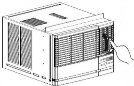
natural_image
Line drawing of an air conditioner unit with a hand inserting a component (no text or symbols)natural_image
Technical line drawing of a computer tower with cooling fan and ventilation slots (no text or symbols)(a)
natural_image
Illustration of a hand washing a solar panel with a faucet above (no text or symbols)(b)
Drenaje
natural_image
Illustration of a computer chassis with hands operating it, showing internal components and a control panel (no text or symbols)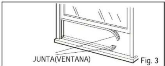
natural_image
Pure mechanical component diagram without any text, numbers, or symbols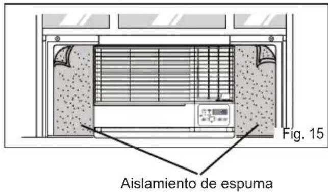
Friedrich Air Conditioning Company
10001 Reunion Place, Suite 500
San Antonio, Tx 78216
800.541.6645
www.friedrich.com
P/NO.: MFL69374602