Force 400M - Fitness Equipment Athletic - Free user manual and instructions
Find the device manual for free Force 400M Athletic in PDF.

| Product Type | Fitness Equipment (Treadmill) |
| Model | Force 400M |
| Brand | Athletic |
| Dimensions (L x W x H) | 180 x 80 x 130 cm |
| Product Weight | 80 kg |
| Max User Weight | 120 kg |
| Motor Power | 3.0 HP Continuous Duty |
| Speed Range | 1 - 20 km/h |
| Incline Range | 0 - 15% |
| Display Type | LCD with blue backlight |
| Programs | 12 preset programs + manual |
| Heart Rate Monitor | Hand pulse sensors |
| Foldable | Yes, with hydraulic assistance |
| Transport Wheels | Yes, front wheels |
| Power Supply | 220V, 50/60 Hz |
| Warranty | 2 years on motor, 1 year on parts |
| Safety Key | Included |
| Maintenance | Lubricate belt every 3 months |
| Cleaning | Wipe with dry cloth, avoid liquids |
| Spare Parts Availability | Contact Athletic customer service |
Frequently Asked Questions - Force 400M Athletic
User questions about Force 400M Athletic
0 question about this device. Answer the ones you know or ask your own.
Ask a new question about this device
Download the instructions for your Fitness Equipment in PDF format for free! Find your manual Force 400M - Athletic and take your electronic device back in hand. On this page are published all the documents necessary for the use of your device. Force 400M by Athletic.
USER MANUAL Force 400M Athletic
natural_image
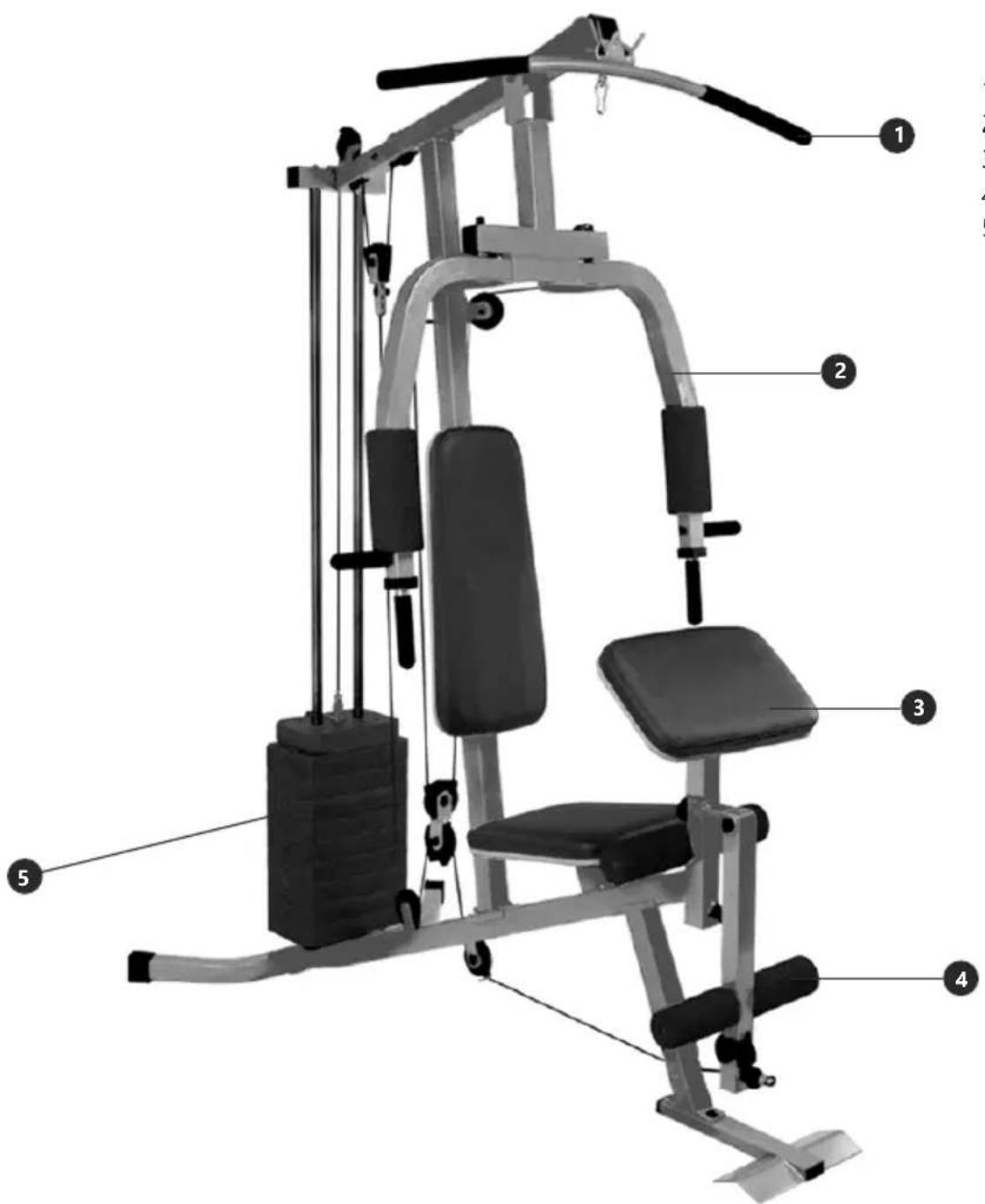
Modern gym machine with adjustable arm and seat, no visible text or symbolsIt is with great pleasure that we offer you the opportunity, guidance and encouragement to practice aerobic and muscular exercises, getting like this, the physical preparation needed to feel good.
We guarantee a reliable and modern product, produced with high technology for people who care about their well-being.
This manual covers the main information, the basic structure and the main operation and preventive maintenance. It will help you familiarize yourself with all the equipment functions, for you enjoy it for a long time.
Carefully read the safety and usage guidelines contained herein. Follow the guidelines for correct assembly of the product.
Caution: Do not push any objects into the openings of the product. Stay clear of moving parts.
Safety and security: it is the owner's responsibility to ensure that all users are properly informed about safety precautions, use, maintenance and care of the product.
SAFETY INFORMATION 5
COMPONENTS AND TECHNICAL SPECIFICATIONS 6
ASSEMBLY....7
PREVENTIVE MAINTENANCE....28
WARRANTY....29
español
Please read this manual before using the product and retain it for future reference to avoid the risk of heating, fire, electric shock, or injury.
It is the owner's responsibility to ensure that all users of the equipment are adequately informed of the safety precautions.
If the equipment is not in perfect condition, call a technical assistant.
General Considerations
- Place the home gym on a flat surface at away from any wall.
- Consult your doctor before starting and during any exercise program. Special attention should be given to children, pregnant women, the elderly, people with heart problems and people with disabilities.
- Keep away from equipment, children and pets, especially during use and do not insert objects into the holes in the equipment.
- Use suitable sportswear. Do not wear loose clothing that can get caught in the equipment. To exercise, always wear shoes, do not walk barefoot or with sandals.
- This device is not intended to be used by people whose physical or mental capacities are reduced or inexperienced, unless they are supervised by a responsible person.
- Children must be supervised to ensure that they do not play with the appliance.
Observations
A. Manufacturer / Distributor is not responsible for accidents and their consequences arising from the violation of the original characteristics or assembly outside the factory settings of their products.
B. Reseller or Authorized Technical Assistance is authorized to change these Terms or make commitments on behalf of the Manufacturer / Distributor.
C. Customer is responsible for unfounded technical call costs.
NOTE: Figures and photos in this manual are for illustrative purposes only. The Manufacturer / Distributor reserves the right to make changes to the product without prior notice. This manual may illustrate options that are not part of the purchased equipment.
COMPONENTS AND TECHNICAL SPECIFICATIONS
- Upper bar
- Arm structure
- Arm curl
- Leg extension
- Weight column
| Product | Packaged | |||
| Net weight (approximate) | 84,7 kg | Gross weight | 90,6 kgBox 1 | Weight Box 1 |
| Maximum width | 1020 mm | Width | 470 mm | 335 mm |
| Maximum length | 1585 mm | Height | 215 mm | 190 mm |
| Maximum height | 2000 mm | Lenght | 1830 mm | 285 mm |

NOTE: Place the packaging with the equipment on a level surface. It is recommended that you place a protective cover for your floor. Exercise caution when you are loading and transporting equipment. Unpack and assemble the equipment where it will be used. If necessary, ask the help of someone else.
COMPONENTS
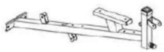
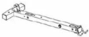
1. Base frame × 1
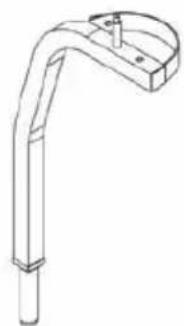
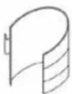
natural_image
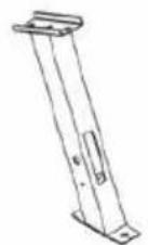
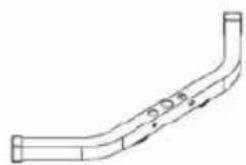
Pure technical line drawing of a bent pipe or duct without any text, labels, or symbols- Rear stabilizer × 1
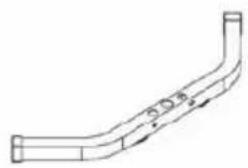
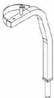
natural_image
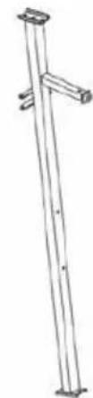
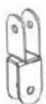
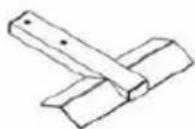
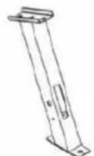
Technical line drawing of a mechanical bracket or support structure (no text or symbols)- Upper frame × 1
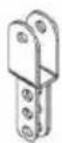
5. Leg developer holder × 1
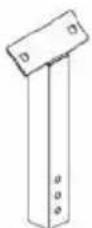
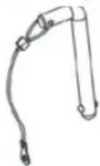
natural_image
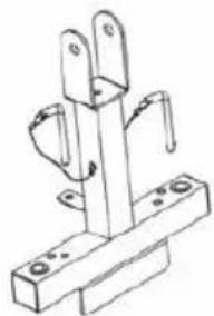
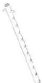
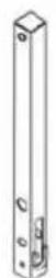
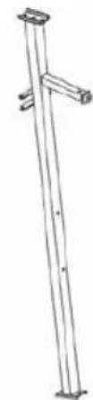
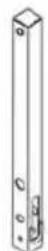
Line drawing of a vertical pole with two legs and a support bracket (no text or symbols)- Vertical frame × 1
natural_image
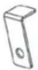
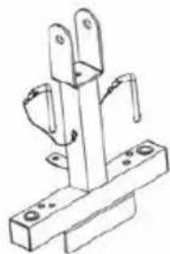
Technical line drawing of a mechanical bracket or support structure (no text or symbols)- Front press base × 1
natural_image
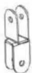
Technical line drawing of a mechanical bracket or support structure (no text or symbols)- Right butterfly × 1
natural_image
Technical line drawing of a mechanical lever or support structure (no text or symbols)- Left butterfly × 1
9. Preacher pad support × 1
10. Floating pulley bracket × 1
11. Angle double pulley bracket × 1
12. Swivel pulley bracket × 2
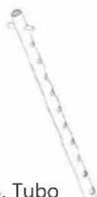
13. Select rod × 1
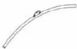
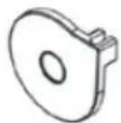
natural_image
Simple line drawing of a curved, elongated object with a small circular mark on the top (no text or symbols)- Lat bar × 1
15. Leg developer × 1
16. Front stabilizer × 1
COMPONENTS
natural_image
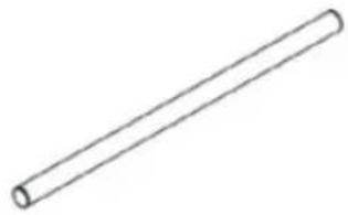
Simple line drawing of a cylindrical rod (no text or symbols)- Foam roll tube × 2
- L-shaped separation blade × 2
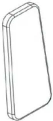
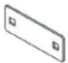
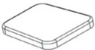
natural_image
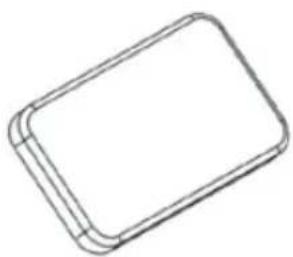
Line drawing of a rectangular electronic device with rounded edges (no text or symbols)- Backrest pad × 1
- Seated press lock pin × 2
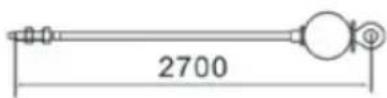
- 2700mm Upper cable × 1
-
Rear U-shaped bracket × 1
-
Guide rod × 2 →
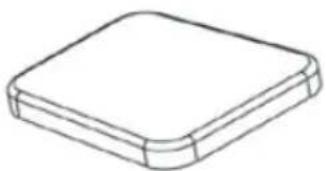
natural_image
Simple line drawing of a rectangular object with rounded edges and a flat top (no text or symbols)- Seat pad × 1
- Pulley cover × 6
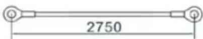
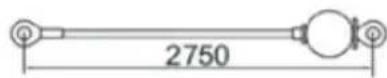
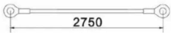
- 2750mm Butterfly cable × 1
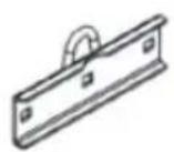
- 120mm Bracket × 3
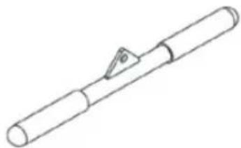
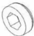
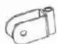
natural_image
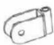
Line drawing of a cylindrical mechanical component with a triangular clip (no text or symbols)- Pull bar × 1
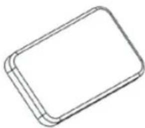
natural_image
Simple line drawing of a rectangular frame with rounded corners (no text or symbols)- Preacher pad × 1
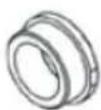
- ∅25mm × 31mm Bushing × 2
- 2750mm Lower cable × 1
COMPONENTS
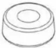
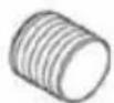
- ∅61mm Rubber bumper × 2
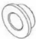
- ∅22 × 11mm Pulley bushing × 2
- Lock knob × 1
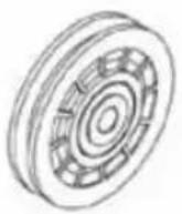
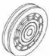
- ∅78mm Pulley × 12
- 30mm Rubber bumper × 1
- ∅22 × 15mm Pulley bushing × 6
natural_image
Simple line drawing of a cylindrical object with a circular top and base (no text or symbols)- ∅17mm Foam roll × 4
natural_image
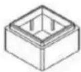
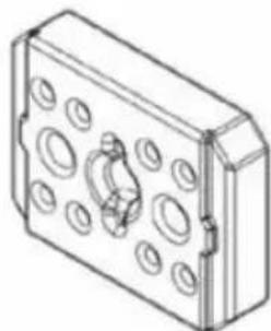
Isometric line drawing of a rectangular mechanical housing with circular holes and a central bolt (no text or symbols)- 3,6kg Upper weight plate x1

- Ankle strap × 1
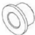
- 45mm ×38mm Sleeve × 1
- M10 Nut cap × 1

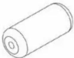
natural_image
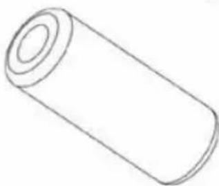
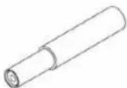
Simple line drawing of a cylindrical object with no text or symbols- ∅45mm Foam roll × 2
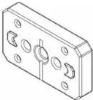
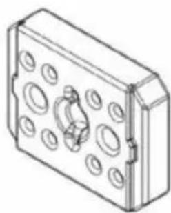
natural_image
Isometric line drawing of a rectangular mechanical housing with multiple circular cutouts and mounting holes (no text or symbols)- 4,5kg Weight plate x9
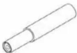
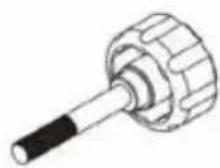
natural_image
Simple line drawing of a cylindrical object with a flanged end (no text or symbols)- Front press handle × 2
COMPONENTS
21 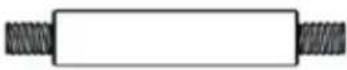 M10 × 103mm Axle × M10 × 103mm Axle × | 27 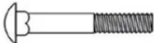 M10 × 65mm Carriage bolt × 8 M10 × 65mm Carriage bolt × 8 | 28 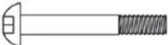 M10 × 65mm Allen bolt × 2 M10 × 65mm Allen bolt × 2 |
29 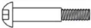 M10 × 60mm Allen bolt × 4 M10 × 60mm Allen bolt × 4 | 30 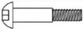 M10 × 55mm Allen bolt × 1 M10 × 55mm Allen bolt × 1 | 31 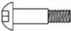 M10 × 42mm Allen bolt × 2 M10 × 42mm Allen bolt × 2 |
32 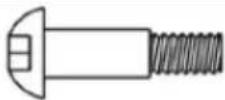 M10 × 40mm Allen bolt × 6 M10 × 40mm Allen bolt × 6 | 33 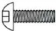 M10 × 30mm Allen bolt × 1 M10 × 30mm Allen bolt × 1 | 34  M10 × 25mm Allen bolt × 6 M10 × 25mm Allen bolt × 6 |
35  M8 × 60mm Allen bolt × 2 M8 × 60mm Allen bolt × 2 | 36  M8 × 18mm Allen bolt × 2 M8 × 18mm Allen bolt × 2 | 37  M6 × 16mm Phillips screw × 1 M6 × 16mm Phillips screw × 1 |
38  ST4.8 Phillips screw × 2 ST4.8 Phillips screw × 2 | 39 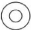 ∅25 × ∅ 11 × 1.5 Washer × 4 ∅25 × ∅ 11 × 1.5 Washer × 4 | 40  ∅ 8mm Washer × 6 ∅ 8mm Washer × 6 |
41  ∅10 Washer × 40 ∅10 Washer × 40 | 42  M10 Aircraft nut × 28 M10 Aircraft nut × 28 | 44 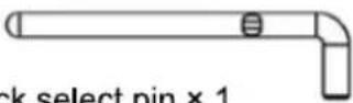 Stack select pin × 1 Stack select pin × 1 |
45  Clip hook × 4 Clip hook × 4 | 47 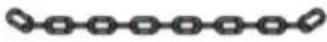 15 Joint chain × 2 15 Joint chain × 2 | 61 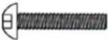 M8 × 40mm Allen bolt × 2 M8 × 40mm Allen bolt × 2 |
75  M10 × 16mm Allen bolt × 2 M10 × 16mm Allen bolt × 2 |  Allen Key 5、6mm Allen Key 5、6mm |
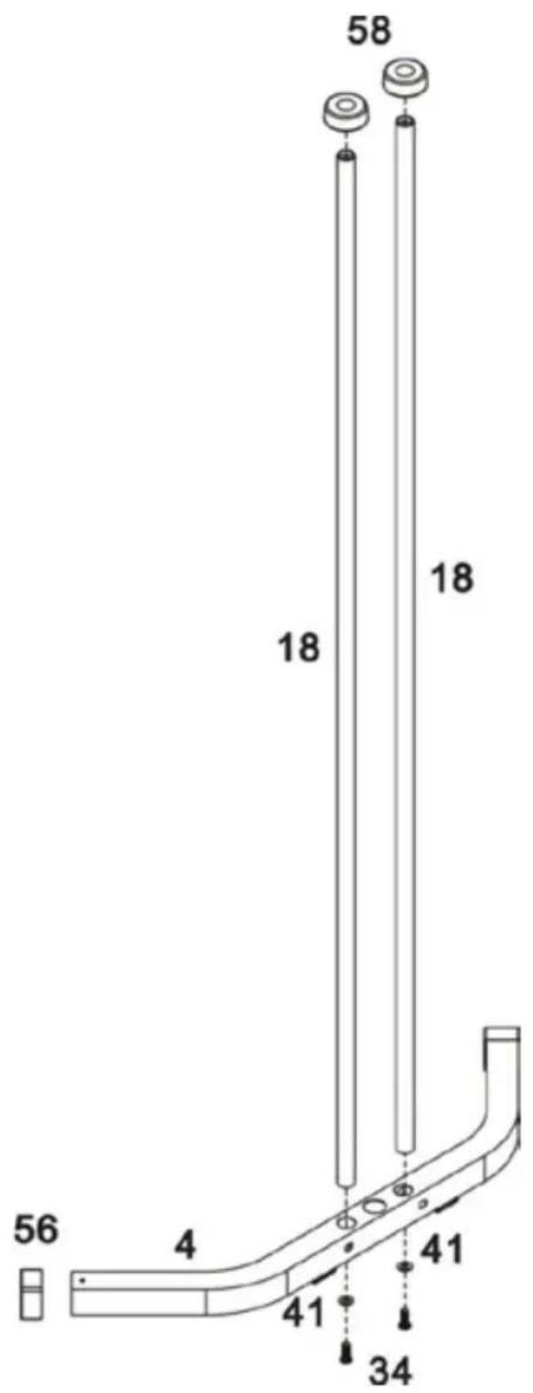
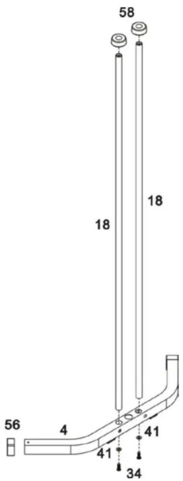
STEP 1

A. Insert the Guide rods (18) into the holes on the Rear stabilizer (4). Fix using 2 x M10 x 25mm Allen bolts (34) and 2 x ∅10mm Washers (41).
B. Slide 2 x ∅61mm Rubber bumpers (58) down onto Guide rods (18).
Note: (56) was fixed in the factory.
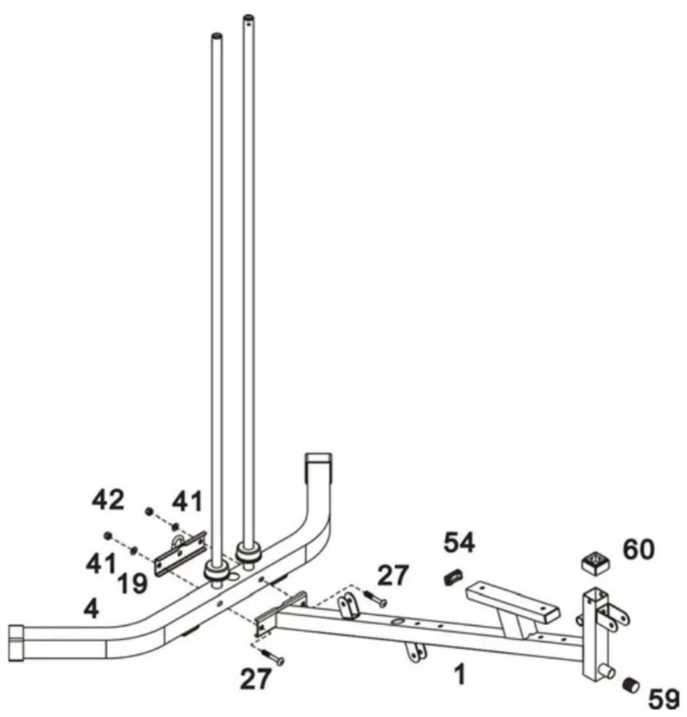
Attach the Base frame (1) to the Rear stabilizer (4). Fix using 2 x M10x 65mm Carriage bolts (27), the Real U-shaped bracket (19), 2 x ∅10mm Washers (41) and 2 x M10 Aircraft nuts (42).
STEP 3
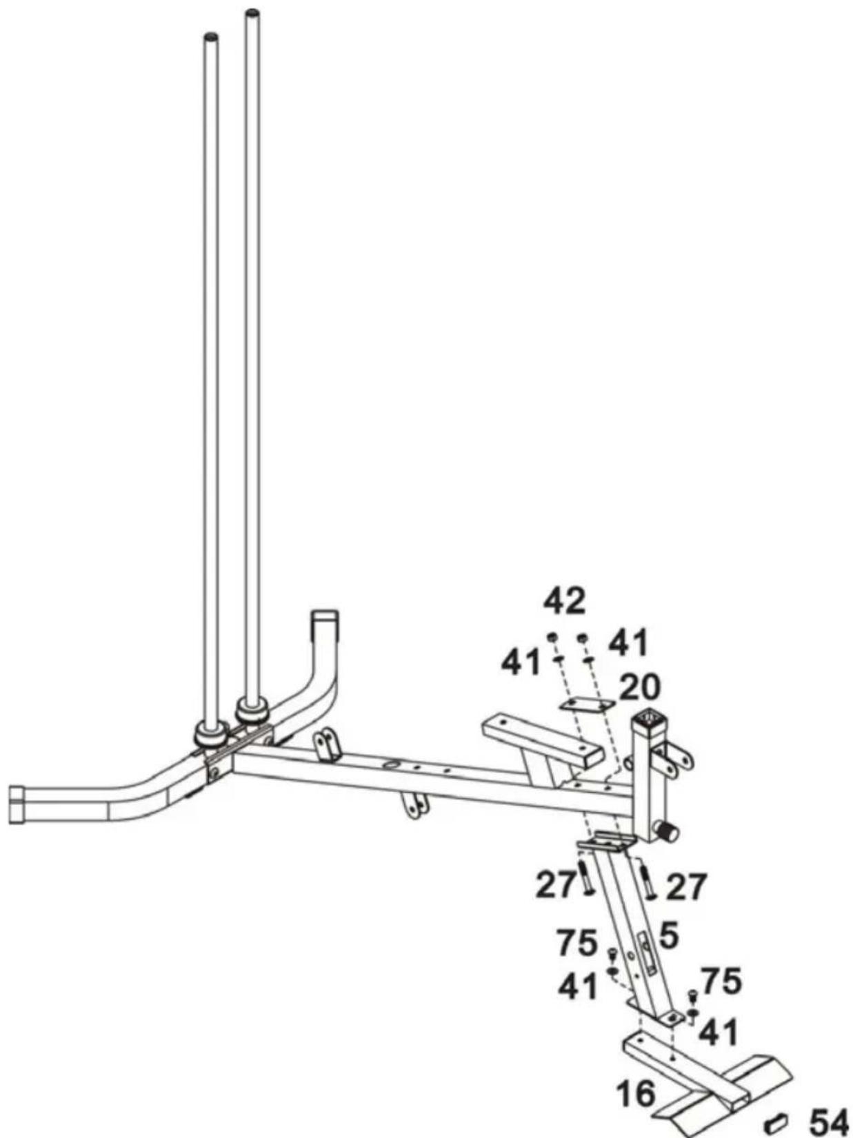
A. Attach the Front stabilizer (16) to the Leg developer holder (5), fix using 2 x M10 x 16mm Allen bolts (75), 2 x ∅10mm Washers (41).
B. Attach the Leg developer holder (5) to the Base frame (1) fix using 120mm Bracket (20), 2 x M10 x 65mm Carriage bolts (27), 2 x ∅10mm Washers (41) and 2 x M10 Aircraft Nuts (42).
Note: (54) was fixed in the factory.
STEP 4
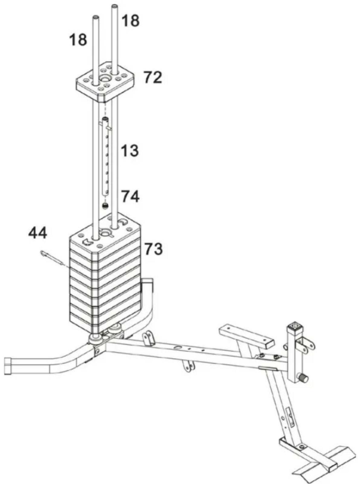
A. Carefully slide 9x 4,5kg Weight plates (73) down Guide rods (18), insert the Select rod (13) into the Weight plates (73), and then slide 1 x 3,6kg Upper weight plate (72) down Guide rods (18)
B. Select the desired training weight by inserting the Stack select pin (44) into the deep grooves under the Weight plates and into the Select rod.
Note: (74) was fixed in the factory.
STEP 5
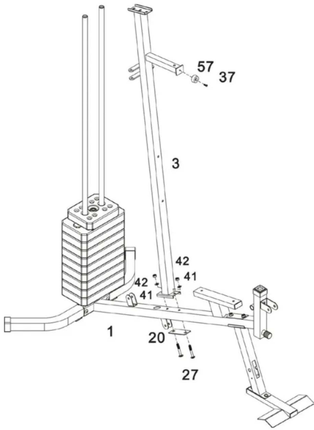
Attach the Vertical frame (3) to the Base frame (1). Fix using 2 x M10 x 65mm Carriage bolts (27), 120mm Bracket (20), 2 x ∅10mm Washers (41) and 2 x M10 Aircraft nuts (42).
Note: (37/57) was fixed in the factory.
STEP 6
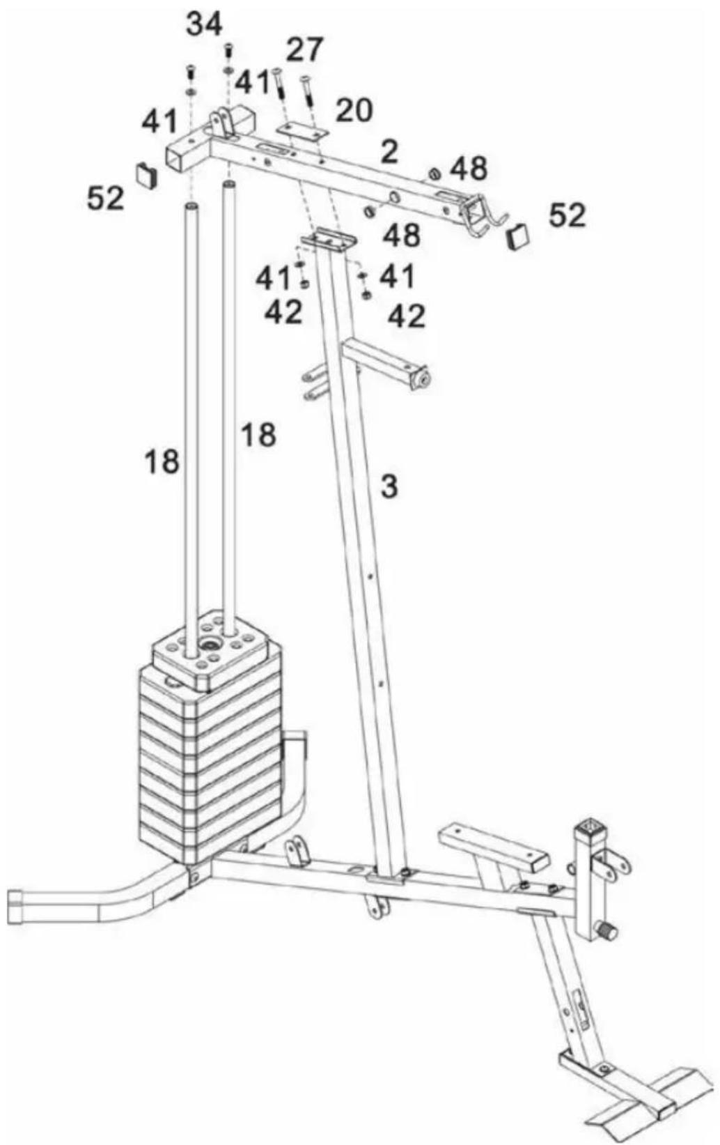
A. Attach Upper frame (2) to Guide rods (18) fix using 2 x M10 x 25mm Allen bolts (34) and 2 x ∅10mm Washers (41).
B. Attach Upper frame (2) to the Vertical frame (3) fix using 2 x M10 x 65mm Carriage bolts (27), 120mm Bracket (20), 2 x ∅10mm Washers (41) and 2 x M10 Aircraft nuts (42),
Note: (52/48) was fixed in the factory.
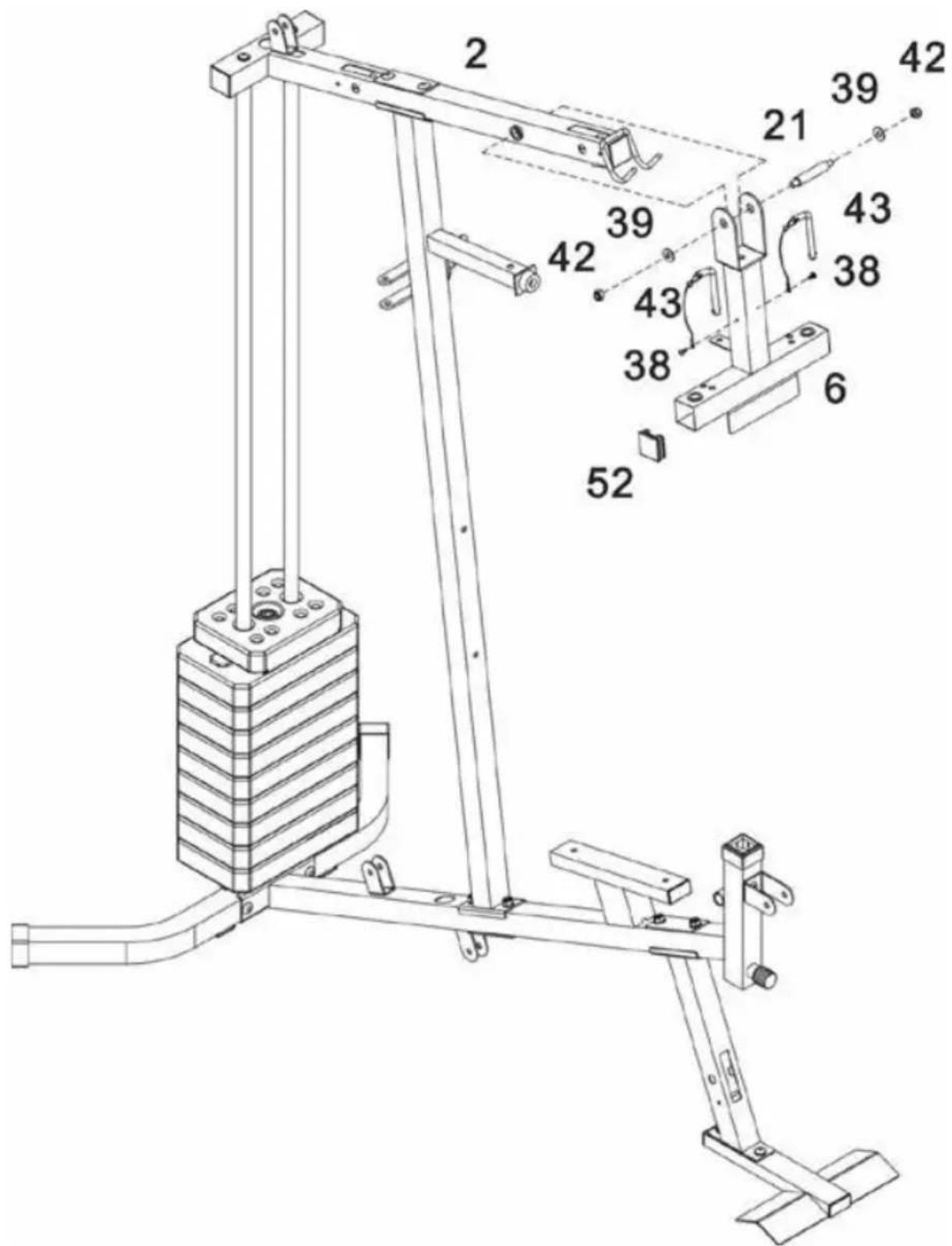
Attach the Front press base (6) to the Upper frame (2) using the M10 x 103mm Axle (21). Secure using 2 x ∅25 x ∅11x1.5 Washers (39) and 2 x M10 Aircraft nuts (42).
Note: (38/43/52) were fixed in the factory.
STEP 8
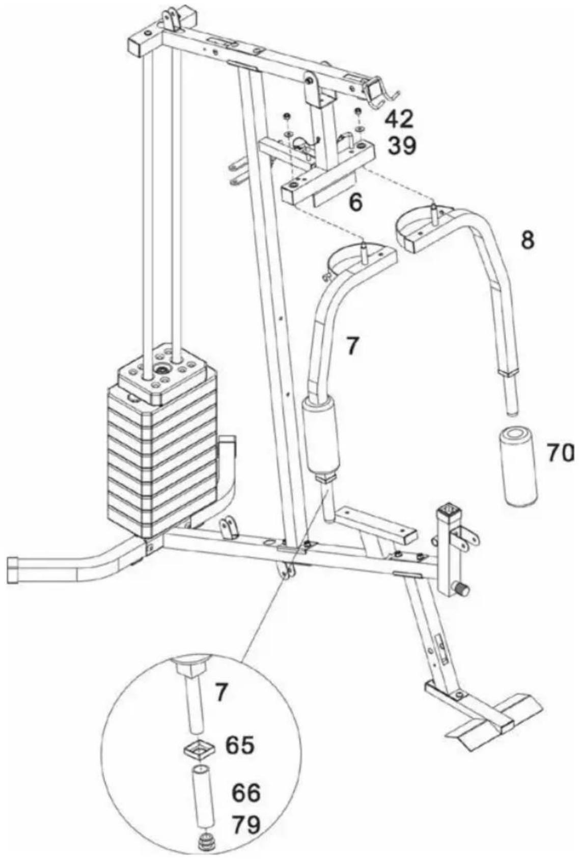
A. Attach the 'pivots' on the Right and Left Butterfly's (7 & 8) to the Front press base (6) using 2 x ∅25 x ∅11 x 1.5 Washers (39) and 2 x M10 Aircraft nuts (42).
B. Slide the 2 x ∅45mm Foam rolls (70) over the end of the Butterfly's (7 & 8).
Note: (65/66) were fixed in the factory.
STEP 9
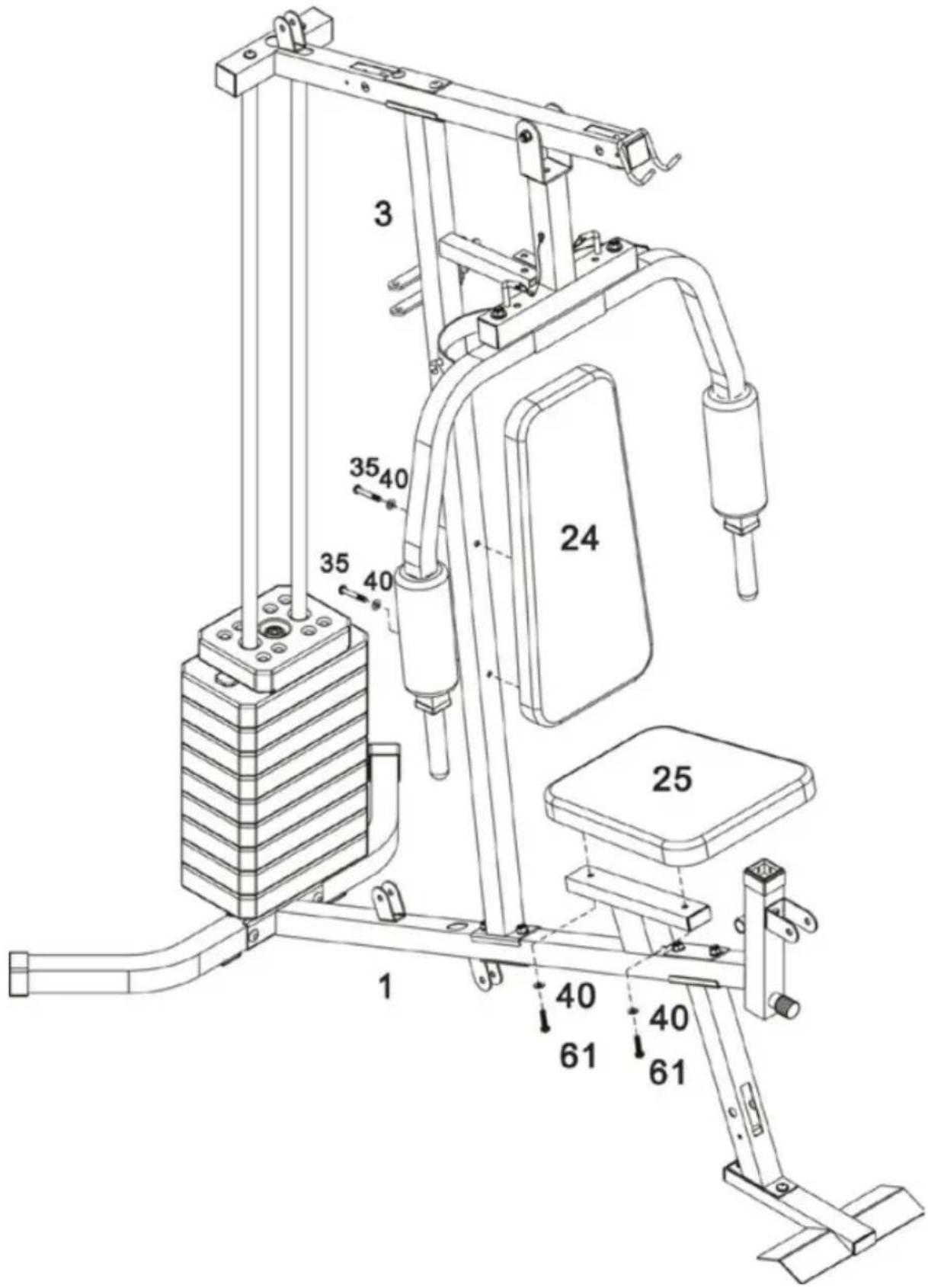
A. Attach the Backrest pad (24) to the Vertical frame (3) using 2 x M8 x 60mm Allen bolts (35) and 2 x ∅8mm Washers (40).
B. Attach the Seat pad (25) to the Base frame (1) using 2 x M8 x 40mm Allen bolts (61) and 2 x ∅8mm Washers (40).
STEP 10
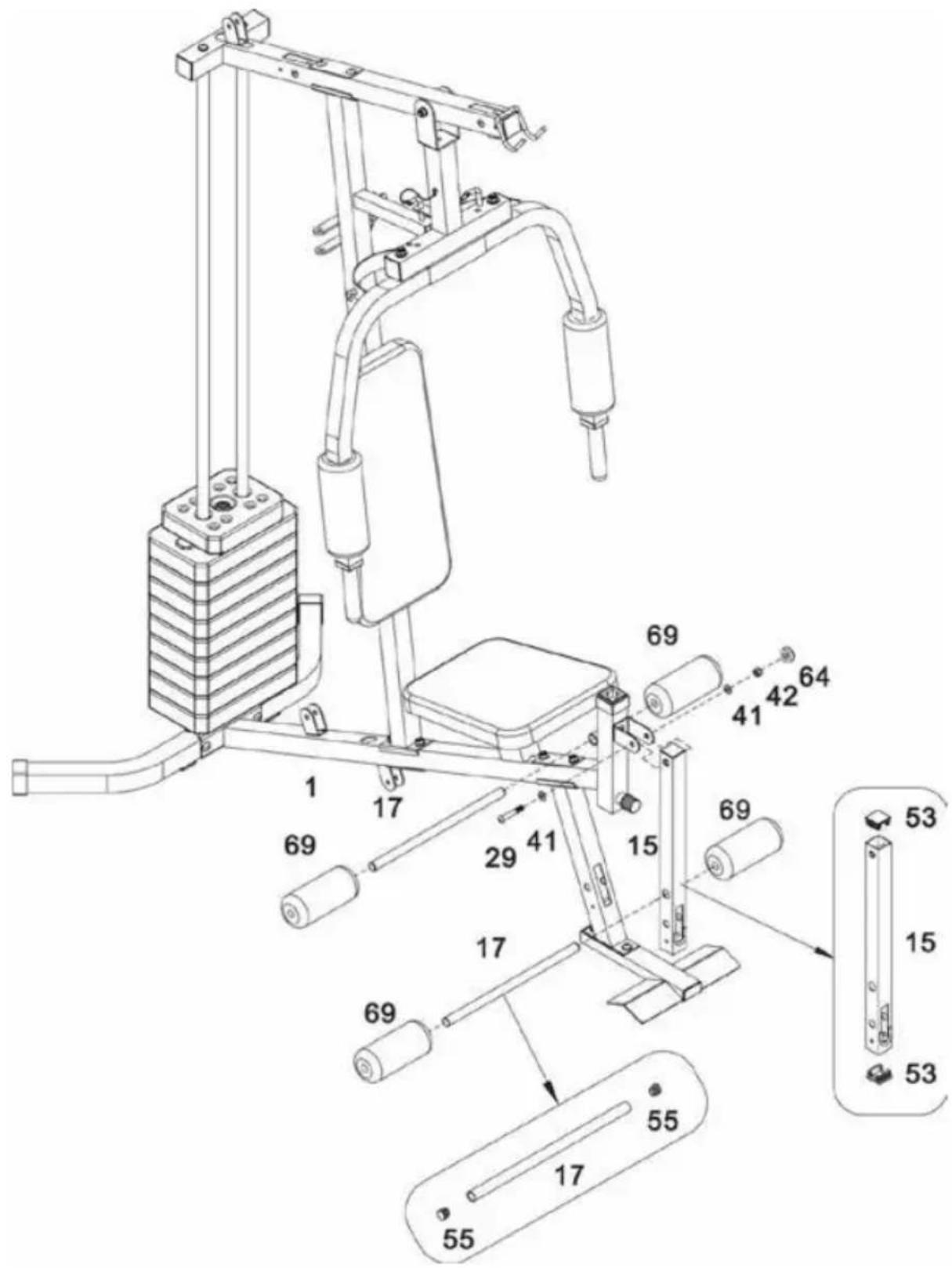
A. Slide the Foam roll tube (17) into the hole on the Base frame (1). Push 2 x ∅17mm Foam rolls (69) onto each side of the Foam roll tube (17).
B. Attach the Leg developer (15) to the Base frame (1) using M10 x 60mm Allen bolts (29) and 2 x ∅10mm Washers (41), M10 Aircraft nut (42) and M10 Nut cap (64).
C. Slide the Foam roll tube (17) into the hole on the Leg developer (15). Push 2 x ∅17mm Foam rolls (69) onto each side of the Foam roll tube (17).
Note: (53/55) were fixed in the factory.
STEP 11
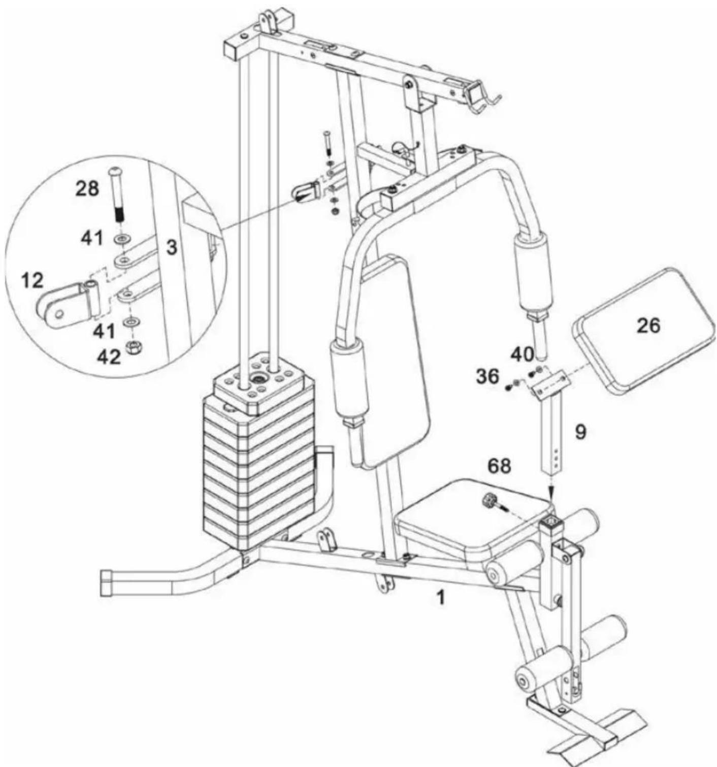
A. Attach the Preacher pad (26) to the Preacher pad stand (9). Secure using 2 x M8 x 18mm Allen bolts (36) and 2 x ∅8mm Washers (40).
B. Insert the Preacher pad assembly into the Base frame (1). Select the desired height and secure using the Lock knob (68).
C. Attach 2 x Swivel pulley brackets (12) to the two sides of open bracket on the Vertical frame (3). Fix using 2 x M10 x 65mm Allen bolts (28), 4 x ∅10mm Washers (41) and 2 x M10 Aircraft nuts (42).
STEP 12
READ THE INSTRUCTIONS FOR THIS ASSEMBLY STEP ON THE NEXT PAGE→
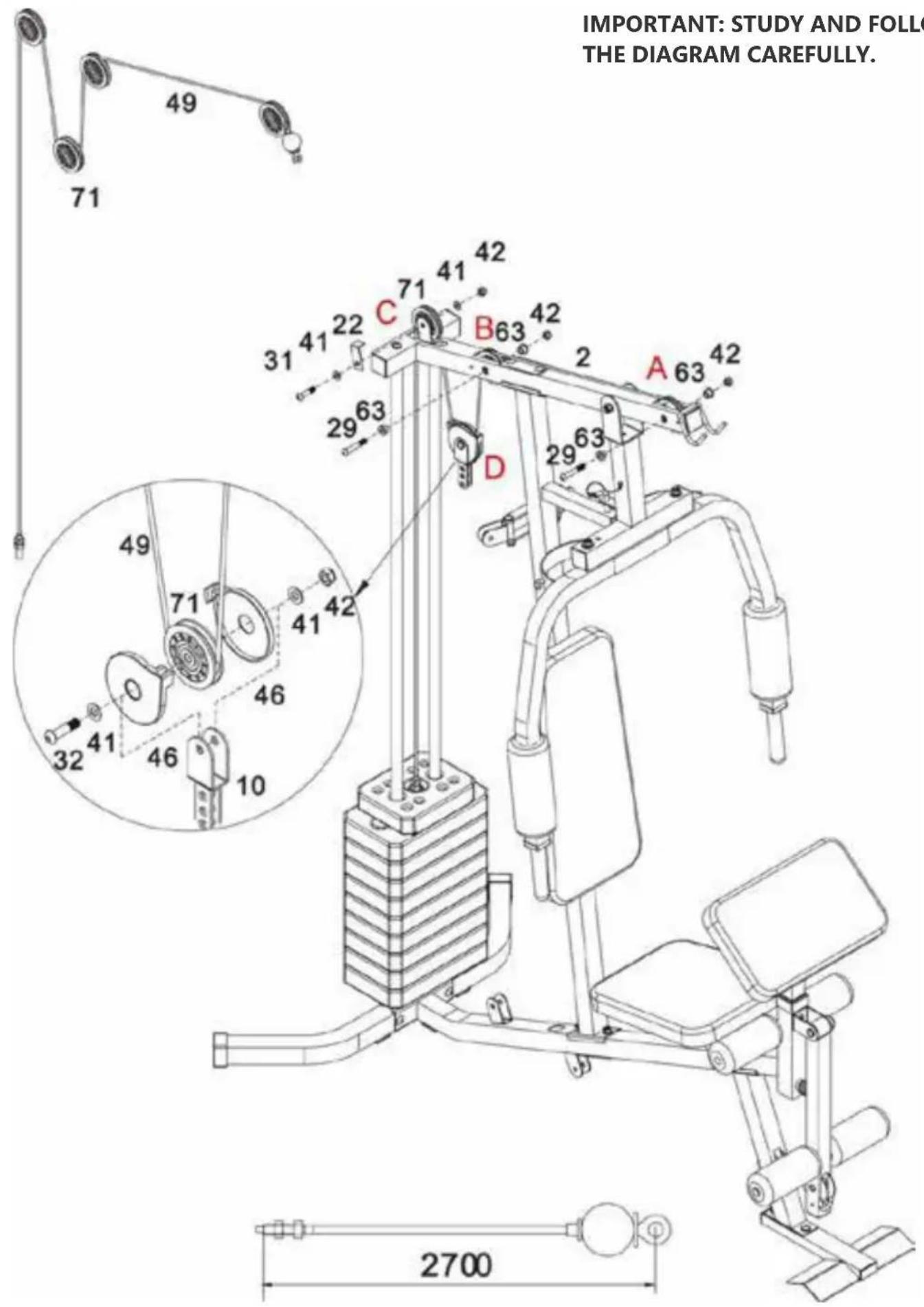
STEP 12
A. Feed the bolt end of the 2700mm Upper cable (49) up through opening in Upper frame (2). Insert ∅22 x 15mm Pulley bushings (63) into holes and attach 1st Pulley (71) using M10 x 60mm Allen bolt (29) and M10 Aircraft nut (42).
B. Repeat procedure for 2nd Pulley, feeding cable up through opening in Upper frame (1).
C. Attach 3rd Pulley to Upper frame (2) using a M10 x 42mm Allen bolt (31), 2 x ∅10mm Washers (41), M10 Aircraft nut (42) and 1 x L-Shaped separation blade (22).
D. Place 4th Pulley (71) onto the cable and fit Pulley covers (46) over Pulley and cable. Attach Pulley assembly to Floating pulley bracket (10) using a M10 x 40mm Allen bolt (32), 2 x ∅10mm Washers (41) and M10 Aircraft nut (42).
STEP 13
IMPORTANT: STUDY AND FOLLOW THE DIAGRAM CAREFULLY.
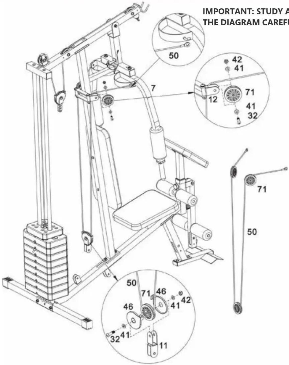
A. Hook one end of the 2750mm Butterfly cable (50) to Right butterfly (7).
Place a ∅77mm Pulley (71) under the cable, position the pulley into the Swivel pulley brackets (12). Fix using M10 x 40mm Allen bolts (32), 2 x ∅10mm Washers (41) and M10 Aircraft nut (42).
B. Repeat "STEP A" to attach the left side.
C. Place a ∅77mm Pulley (71) onto the cable and fit Pulley covers (46) over Pulley and cable. Attach Pulley assembly to Angle double pulley bracket (11) using M10 x 40mm Allen bolt (32), 2 x ∅10mm Washers (41) and M10 Aircraft nut (42).
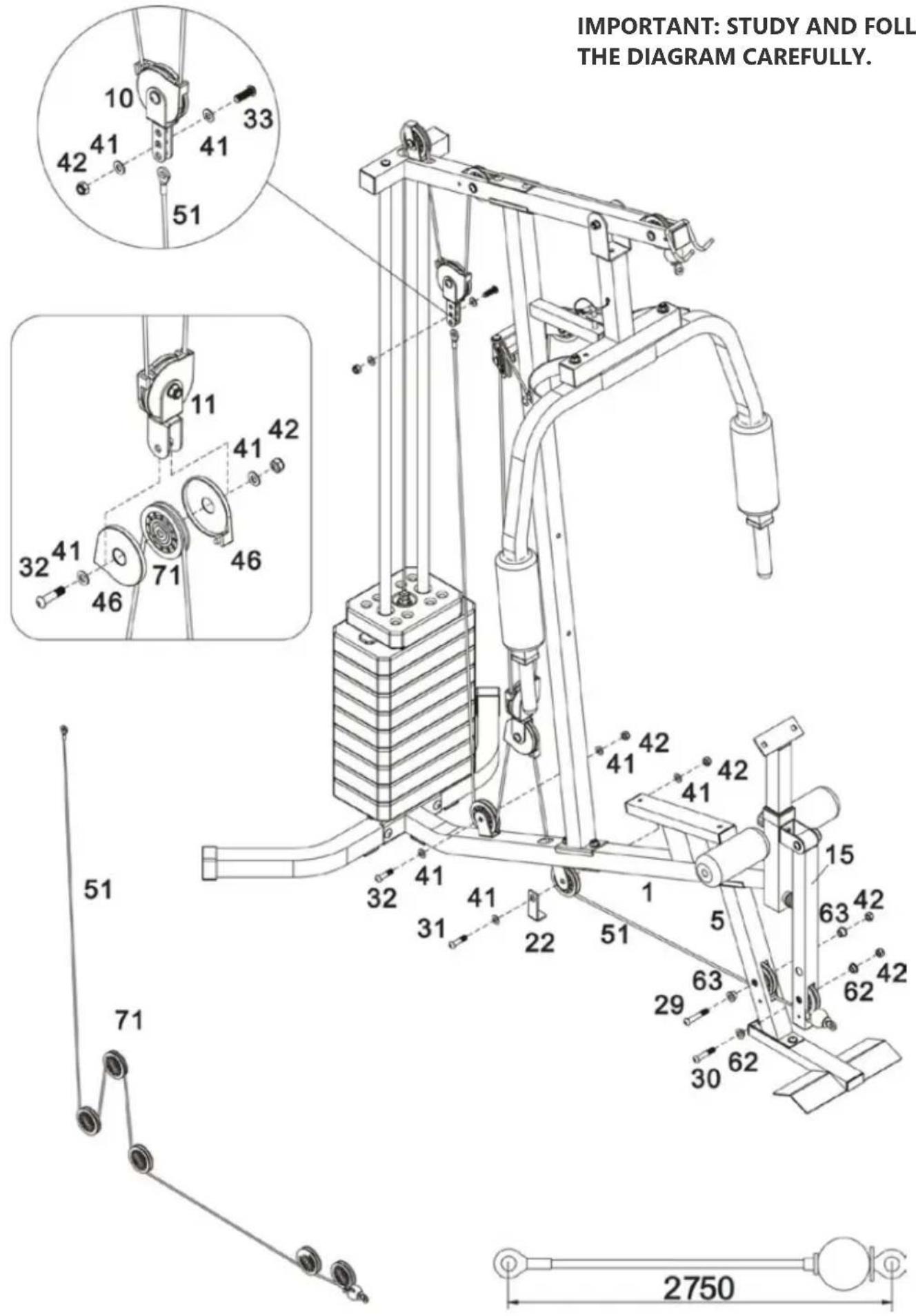
STEP 14
IMPORTANT: STUDY AND FOLLOW THE DIAGRAM CAREFULLY.
READ THE INSTRUCTIONS FOR THIS ASSEMBLY STEP ON THE NEXT PAGE→
STEP 14
A. Feed the loop end of 2750mm Lower cable (51) through opening in the Leg developer (15). Insert 2 x ∅22 x 11mm Pulley bushings (62) into holes and attach 1st Pulley using M10 x 53mm Allen bolt (30) and M10 Aircraft nut (42).
B. Insert 2 x ∅22 x 15mm Pulley bushings (63) into holes and attach 2nd Pulley using M10 x 60mm Allen bolt (29) and M10 Aircraft nut (42).
C. Attach 3rd Pulley to Base frame (1) using a M10 x 42mm Allen bolt (31), 2 x ∅10mm Washers (41), M10 Aircraft nut (42) and 1 x L-Shaped separation blade (22).
D. Place 4th Pulley onto the cable and fit Pulley covers (46) over Pulley and cable. Attach Pulley assembly to the other end of the Angled double pulley bracket (11) using M10 x 40mm Allen bolt (32), 2 x ∅10mm Washers (41) and M10 Aircraft nut (42).
E. Attach 5th Pulley to Base frame (1) using M10 x 40mm Allen bolt (32), 2 x ∅10mm Washers (41) and M10 Aircraft nut (42).
F. Secure the end of the Lower cable (51) to the Floating pulley bracket (10) using M10 x 30mm Allen bolt (33), 2 x ∅10mm Washers (41) and M10 Aircraft nut (42).
Important: Now fully tighten the fixings ensuring that all of the pulleys and brackets can move freely.
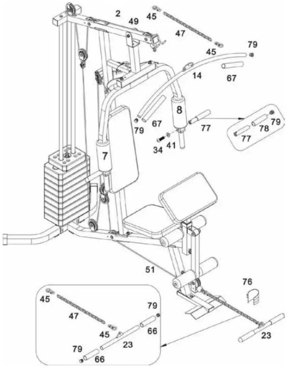
Attach the Lat bar (14) onto the Upper frame (2) hooks.
Connect the Pull bar (23) to the end of Lower cable (51) using 2 x Clip hooks (45) and 15 Joint chain (47). Attach 2 x Front press handle (77) to the Right/Left butterfly (7&8). Fix using 2 x M10 x 25mm Allen bolt (34) and 2 x ∅10mm Washers (41).
Note: (66/67) was fixed in the factory.
Before you use your equipment make sure it is in good condition. Check the general condition of the equipment, as described in "Safety Information". If the equipment is not in perfect condition, contact an Authorized Technical Assistant.
CLEANING:
- Never use abrasive or solvents for cleaning.
- Do not leave the equipment exposed to natural agents such as sunlight, rain, dew, dust, salt spray etc.
- Do not put the equipment in dusty environments, wet, saunas or anywhere unventilated.
- Always use original spare parts. Improper maintenance can cause damage to the product and loss of warranty.
- If you prefer, this cleaning can be done by a Technical Assistant (see values).
WARNING: This equipment is designed for residential use. We assume no responsibility when it is used by gyms, clubs, clinics or condos.
Terms of Guarantee
A. The warranty procedures will be carried out only upon presentation of the note / original coupon tax of Sale and limitations laid down by these Terms. The guarantee shall be provided by the Authorized Technical Assistance Network.
B. The conditions set out in this Agreement are guaranteed to the first user purchaser of this product for a period of 6 (six) months (including the legal guarantee period - first 90 (ninety) days, counted from the date of issuance of the note / tax Coupon sale, in the event of exclusively residential use.
C. Warranty and coverage terms start to count from the date of issue of the sales invoice / coupon, including the legal term of 90 (ninety) days.
PARTS AND COMPONENTS
| Structure | 6 months |
| Painting (oxidation) | 6 months |
| Cables | 90 days |
| Plastic, leather and rubber parts | 6 months |
| Manpower | 6 months |
D. Parts repaired or replaced under this warranty does not stop nor extend the warranty period originally stipulated.
E. To be used by this warranty, the equipment must have been installed by authorized technical assistant, except for residential products.
F. Warranty does not cover the installation and preventive maintenance services such as cleaning, lubrication and adjustment of the product.
G. No dealer is authorized to receive client product to refer you local dealer or this take it to return to it and to provide information on behalf of the Manufacturer / Supplier of the progress of the service. The manufacturer / supplier or consumer support are not responsible for any damage or delay due to this non-compliance. H. The Manufacturer / Supplier keep available spare parts until they cease the manufacture or import the equipment. If it ceased the production or import of equipment Manufacturer / Supplier keep the spare supply its line of equipment for a reasonable period of time, according to the law.
1. Within the period of thirty (30) days if the equipment presents some malfunction, the customer may choose to take the product to an authorized posts or requesting service in your home without travel expenses in those counties covered by the Network Authorized Service. After the period of thirty (30) days or in municipalities not covered by the Technical Assistance Network Authorized expenses resulting from any transport of the equipment to a freight service, removal or technical visit by technical assistant, occur by the customer, whether or not this equipment covered by
this warranty.
J. Lubricants, silicones for treadmills, vaseline to the guide weights and micro oil to the joints of weight stations, should be exclusively recommended by the manufacturer, available at Authorized Technical Assistance Network.
K. Components that wear out with regular use of equipment such as motor brushes, belts, pads, brake bands, felt, steel chains and cables, when this equipment will have warranty for a period of 90 days from the invoice or manufacturing defect found by the Authorized Technical Assistance Network.
Extinction Assurance
This warranty will be considered void when:
A. Expiry of the warranty term.
B. Equipment repaired by a person not authorized by the Manufacturer / Supplier, if signs of violation of its original characteristics or non-factory assembly are found.
C. Damage suffered by the equipment due to improper use, use of inappropriate cleaning products, oxidation from external agents, wear, neglect, modification, use of accessories not recommended, inadequate design for the intended application, falls, perforations, use and opposite installation to the operating instructions, inadequate wiring in the electrical network, lack of grounding in badly sized grids and / or excessive fluctuations and overloads.
D. For residential line is prohibited any type of user equipment maintenance or a third party other than the technical assistance network.
E. The product is used in gyms, condominiums, clinics, clubs, sauna, submerged in water or use so that it resembles other than for residential purpose or the application of the purpose intended.
Comments:
A. cables, carabiners, pedals when existing in the product should be replaced once a year.
B. The Manufacturer / Supplier is not responsible for any accidents and their consequences, arising from breach of the original features or assembly out of their equipment factory default.
C. Customer's responsibility are those resulting from unfounded judged answering calls.
Note: Manufacturer / Supplier reserves the right to make changes without notice this.
natural_image
Technical line drawing of a mechanical bracket or frame assembly (no text or symbols)2 - Estructura superior - x1

natural_image
Simple line drawing of a vertical pole with two legs and a handle (no text or symbols)3 - Estructura vertical - x1

natural_image
Technical line drawing of a bent pipe or duct (no text or symbols)natural_image
Technical line drawing of a mechanical bracket or support structure (no text or symbols)natural_image
Technical line drawing of a mechanical bracket or support structure (no text or symbols)natural_image
Technical line drawing of a mechanical lever or support structure (no text or symbols)natural_image
Simple line drawing of a curved, elongated object with a small circular mark on the top (no text or symbols)14 - Barra superior - x1
11. Soporte duplo de poleas x 1
12. Soporte giratorio de poleas x 1
13. Tubo selector x 1
natural_image
Simple line drawing of a straight cylindrical rod (no text or symbols)natural_image
Simple line drawing of a rectangular object with rounded edges, resembling a smartphone or electronic device (no text or symbols)- Respaldo x 1
natural_image
Simple line drawing of a rectangular object with rounded edges and a flat top (no text or symbols)- Asiento x 1

natural_image
Simple line drawing of a rectangular frame with rounded corners (no text or symbols)- Curl de brazos x 1
natural_image
Simple line drawing of a cylindrical object with rounded ends and a central hole (no text or symbols)natural_image
Simple line drawing of a cylindrical object with no text or symbolsnatural_image
Isometric line drawing of a mechanical housing or enclosure with circular holes and a central bolt (no text or symbols)natural_image
Isometric line drawing of a mechanical housing component with multiple circular holes and a central slot (no text or symbols)- Placa de peso 4,5kg x9
76. Correa del tobillo x 1

natural_image
Simple line drawing of a cylindrical object with a flanged end (no text or symbols)- Manillar x 2
COMPONENTS
21 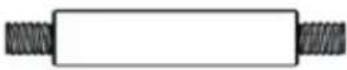 Eje M10 x 103mm x 1 Perno M10 x 65mm x 8 Perno allen M10x65mm x 2 Eje M10 x 103mm x 1 Perno M10 x 65mm x 8 Perno allen M10x65mm x 2 | 27 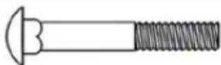 | 28  |
29  Perno allen M10x60mm x 4 Perno allen M10x55mm x 1 Perno allen M10x42mm x 2 Perno allen M10x60mm x 4 Perno allen M10x55mm x 1 Perno allen M10x42mm x 2 | 30  | 31  |
32  Perno allen M10x40mm x 6 Perno allen M10x30mm x 1 Perno allen M10x25mm x 6 Perno allen M10x40mm x 6 Perno allen M10x30mm x 1 Perno allen M10x25mm x 6 | 33  | 34 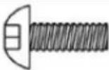 |
35 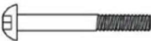 Perno allen M8x60mm x 2 Perno allen M8x18mm x 2 Perno allen M8x60mm x 2 Perno allen M8x18mm x 2 | 36 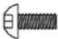 | 37  Perno Philips M6x16mm x 1 Perno Philips M6x16mm x 1 |
38 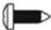 Tornillo Philips ST4.8 x 2 Tornillo Philips ST4.8 x 2 | 39 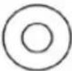 Arandela ∅25x∅11x1.5 x 4 Arandela ∅25x∅11x1.5 x 4 | 40  Arandela ∅8mm x 6 Arandela ∅8mm x 6 |
41  Arandela ∅10mm x 40 Arandela ∅10mm x 40 | 42  Contratuercas M10 x 28 Contratuercas M10 x 28 | 44 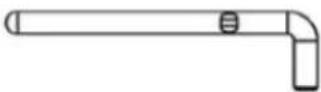 Pasador selector de peso x 1 Pasador selector de peso x 1 |
45 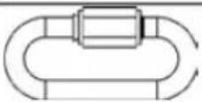 Gancho x 4 Cadena x 2 Perno allen M8x40mm x 2 Gancho x 4 Cadena x 2 Perno allen M8x40mm x 2 | 47 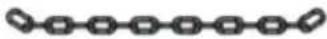 | 61 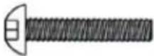 |
75 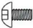 Perno allen M10x16mm x 2 Perno allen M10x16mm x 2 | 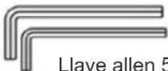 Llave allen 6 Llave allen 6 |
PASO 1
A. Conectar la Estructura superior (2) a las Barras guía (18) con 2 Pernos allen M10 x 25 mm (34) y 2 Arandelas ∅10mm (41).
B. Fije la Estructura superior (2) en la Estructura vertical (3) con 2 Pernos M10 x 65 mm (27), Soporte de 120 mm (20), 2 Arandelas ∅10 mm (41) y 2 Contratuercas M10 (42).
natural_image
Technical line drawing of a mechanical bracket or frame assembly (no text or symbols)2 - Estrutura superior - x1
natural_image
Simple line drawing of a vertical pole with two legs and a handle (no text or symbols)3 - Estrutura vertical - x1
natural_image
Technical line drawing of a bent pipe or duct (no text or symbols)4 - Estabilizador traseiro - x1
5 - Estrutura frontal - x1
natural_image
Technical line drawing of a mechanical bracket or support structure (no text or symbols)natural_image
Technical line drawing of a mechanical bracket or support structure (no text or symbols)natural_image
Technical line drawing of a mechanical lever or support structure (no text or symbols)natural_image
Simple line drawing of a curved, elongated object with a small circular mark on the top (no text or symbols)14 - Barra superior - x1
15. Estrutura do Extensor de pernas x 1
natural_image
Simple line drawing of a cylindrical rod (no text or symbols)- Tubo do rolo de espuma x 2
natural_image
Simple line drawing of a rectangular object with rounded edges, resembling a smartphone or electronic device (no text or symbols)- Encosto x 1

natural_image
Simple line drawing of a rectangular object with rounded edges and a flat top (no text or symbols)- Assento x 1
natural_image
Simple line drawing of a rectangular frame with rounded corners (no text or symbols)- Apoio de braços x 1
natural_image
Simple line drawing of a cylindrical object with rounded ends and a central hole (no text or symbols)- Rolo de espuma ∅17mm x 4
natural_image
Simple line drawing of a cylindrical object with no text or symbols- Rolo de espuma ∅45mm x 2
71. Polia ∅78 x 12
natural_image
Isometric line drawing of a mechanical housing or enclosure with circular holes and a central bolt (no text or symbols)natural_image
Isometric line drawing of a mechanical housing component with multiple circular holes and a central slot (no text or symbols)- Placa de peso 4,5kg x9

76. Alça de
tornozelo x 1
natural_image
Simple line drawing of a cylindrical object with a flanged end (no text or symbols)- Pegador x 2
COMPONENTS
| 21 Eixo M10 x 103mm x 1 Parafuso M10 x 65mm x 8 Parafuso allen M10x65mm x 2 | 27 | 28 |
| 29 Parafuso allen M10x60mm x 4 Parafuso allen M10x55mm x 1 Parafuso allen M10x42mm x 2 | 30 | 31 |
| 32 Parafuso allen M10x40mm x 6 Parafuso allen M10x30mm x 1 Parafuso allen M10x25mm x 6 | 33 | 34 |
| 35 Parafuso allen M8x60mm x 2 Parafuso allen M8x18mm x 2 | 36 | 37 Parafuso Philips M6x16mm x 1 |
| 38 Parafuso Philips ST4.8 x 2 | 39 Arruela ∅25x∅11x1.5 x 4 | 40 Arruela ∅8mm x 6 |
| 41 Arruela ∅10mm x 40 | 42  Porcas M10 x 28 Porcas M10 x 28 | 44 Pino seletor de peso x 1 |
| 45 Gancho x 4 Corrente x 2 Parafuso allen M8x40mm x 2 | 47 | 61 |
75 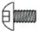 Parafuso allen M10x16mm x 2 Parafuso allen M10x16mm x 2 | 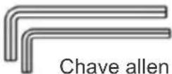 Chave allen 6 Chave allen 6 |