HDVR-1635 - Video recorder Planet - Free user manual and instructions
Find the device manual for free HDVR-1635 Planet in PDF.

User questions about HDVR-1635 Planet
0 question about this device. Answer the ones you know or ask your own.
Ask a new question about this device
Download the instructions for your Video recorder in PDF format for free! Find your manual HDVR-1635 - Planet and take your electronic device back in hand. On this page are published all the documents necessary for the use of your device. HDVR-1635 by Planet.
USER MANUAL HDVR-1635 Planet
natural_image
Black PLANNET Hybrid Digital Video Recorder device with control buttons and ports (no visible text beyond branding)4-/8-/16-Channel H.265 Hybrid Digital Video Recorder
HDVR-435
HDVR-835
HDVR-1635

natural_image
Group of business professionals in a meeting around a laptop, engaged in discussion (no visible text or symbols)Copyright
Copyright © 2019 by PLANET Technology Corp. All rights reserved. No part of this publication may be reproduced, transmitted, transcribed, stored in a retrieval system, or translated into any language or computer language, in any form or by any means, electronic, mechanical, magnetic, optical, chemical, manual or otherwise, without the prior written permission of PLANET.
PLANET makes no representations or warranties, either expressed or implied, with respect to the contents hereof and specifically disclaims any warranties, merchantability or fitness for any particular purpose. Any software described in this manual is sold or licensed "as is". Should the programs prove defective following their purchase, the buyer (and not PLANET, its distributor, or its dealer) assumes the entire cost of all necessary servicing, repair, and any incidental or consequential damages resulting from any defect in the software. Further, PLANET reserves the right to revise this publication and to make changes from time to time in the contents hereof without obligation to notify any person of such revision or changes.
All brand and product names mentioned in this manual are trademarks and/or registered trademarks of their respective holders.
Federal Communication Commission (FCC) Interference Statement
This equipment has been tested and found to comply with the limits for a Class B digital device, pursuant to Part 15 of FCC Rules. These limits are designed to provide reasonable protection against harmful interference in a residential installation. This equipment generates, uses, and can radiate radio frequency energy and, if not installed and used in accordance with the instructions, may cause harmful interference to radio communications. However, there is no guarantee that interference will not occur in a particular installation. If this equipment does cause harmful interference to radio or television reception, which can be determined by turning the equipment off and on, the user is encouraged to try to correct the interference by one or more of the following measures:
- Reorient or relocate the receiving antenna.
- Increase the separation between the equipment and receiver.
- Connect the equipment into an outlet on a circuit different from that to which the receiver is connected.
- Consult the dealer or an experienced radio technician for help.
FCC Caution
To assure continued compliance, for example, use only shielded interface cables when connecting to computer or peripheral devices. Any changes or modifications not expressly approved by the party responsible for compliance could void the user's authority to operate the equipment.
This device complies with Part 15 of the FCC Rules. Operation is subject to the following two conditions: (1) This device may not cause harmful interference, and (2) this device must accept any interference received, including interference that may cause undesired operation.
FCC Radiation Exposure Statement
This equipment complies with FCC radiation exposure set forth for an uncontrolled environment. In order to avoid the possibility of exceeding the FCC radio frequency exposure limits, human proximity to the antenna shall not be less than 20 cm (8 inches) during normal operation.
Safety
This equipment is designed with the utmost care for the safety of those who install and use it. However, special attention must be paid to the dangers of electric shock and static electricity when working with electrical equipment. All guidelines of this and of the computer manufacture must therefore be allowed at all times to ensure the safe use of the equipment.
CE Mark Warning
This is a Class B product. In a domestic environment, this product may cause radio interference, in which case the user may be required to take adequate measures.
WEEE Regulation

To avoid the potential effects on the environment and human health as a result of the presence of hazardous substances in electrical and electronic equipment, end users of electrical and electronic equipment should understand the meaning of the crossed-out wheeled bin symbol. Do not dispose of WEEE as unsorted municipal waste; they should be collected separately.
Revision
User's Manual of PLANET H.265 Hybrid Digital Video Recorder
Model: HDVR-435/HDVR-835/HDVR-1635
Rev: 1.0 (June 2019)
Part No. EM-HDVR-435_835_1635_v1.0
Table of Contents
Chapter 1. Product Introduction......8
1.1 Package Contents 8
1.2 Overview....9
1.3 Features .... 10
1.4 Product Specifications .... 11
Chapter 2. Hardware Interface....15
2.1 Physical Descriptions....15
2.2 Hardware Installation....17
2.2.1 Installing Hard Disk....17
Chapter 3. Connecting to the HDVR....19
3.1 Using Search Tool Utility....19
3.2 Accessing HDVR with its default IP address....21
Chapter 4. Basic Operation....23
4.1 Main/Live Viewing....23
4.2 Preview....24
4.3 Desktop Shortcut Menu 24
4.3.1 Main Menu....25
4.3.2 Window Switch 25
4.3.3 Guide....26
4.3.4 PTZ Control 26
4.3.5 Coaxial Control 27
4.3.6 Preview Signal....28
4.3.7 Color Setting....28
4.3.8 Playback....29
4.3.9 Record....31
4.3.10 Channel Type 31
4.3.11 Camera Management 32
Chapter 5. Main Menu ....33
5.1 Main Menu Navigation....33
5.2 Record....35
5.2.1 Record Configuration....35
5.3 Playback....37
5.4 Backup....37
5.5 Sensor Function 38
5.5.1 Motion Detection....38
5.5.2 Video Blind....42
5.5.3 Video Loss....42
5.5.4 Abnormality....43
5.6 System Setup 44
5.6.1 General....44
5.6.2 Encode Setup 45
5.6.3 GUI Display....47
5.6.4 PTZ/RS485 Device 50
5.6.5 Tour....52
5.6.6 Output Adjust....53
5.6.7 Restore....54
5.6.8 RS232....54
5.6.9 Account....55
5.7 Advanced....58
5.7.1 Version....58
5.7.2 Log....59
5.7.3 BPS....59
5.7.4 Online User....60
5.7.5 Device Info....60
5.7.6 Upgrade....61
5.7.7 Auto Maintain....61
5.7.8 Import/Export 61
5.8 HDD Management....62
5.8.1 HDD Info....63
5.9 Network 64
5.9.1 Network Setup....64
5.9.2 DDNS....65
5.9.3 UPNP....66
5.9.4 EMAIL....67
5.9.5 Cloud 68
5.9.6 Net Service 69
5.10Camera....78
5.11 Logout....84
Chapter 6. Web Remote Management ....86
6.1 Connecting to HDVR 86
6.2 Live View on Browser 88
Appendix A: Ping IP Address....89
Appendix B: Planet DDNS Application....90
Appendix C: Configuring Port Forwarding Manually .....91
Chapter 1. Product Introduction
1.1 Package Contents
The package should contain the following items:
HDVR Unit x 1
- Screw Kit x 1
● Power Adapter x 1
- Quick Installation Guide x 1
- SATA Cable x 1
- SATA Power Cable x 1
- RS485 Connector x 1

Note
- If any of the above items are missing, please contact your dealer immediately.
- Using the power supply that is not the one included in the HDVR packet will cause damage and void the warranty for this product.
- SATA cable, SATA power cable and RS485 connector are included in the HDVR.
1.2 Overview
Efficient Solution for All Video Formats
PLANET HDVR-435, 835, and 1635 are H.265 Hybrid DVR recorders which are able to record video and data from traditional AHD (analog high definition), HD-CVI (high definition composite video interface), HD-TVI (high definition transport video interface) and Network IP security cameras. The advantage of a hybrid DVR recorder is that it lets you use currently installed analog security equipment along with newer network IP technology. This enables you to upgrade your surveillance system to IP equipment at your own pace, according to your budget. The HDVR-435/835/1635 4-/8-/16-channel embedded system is equipped with HDMI/VGA local display and features recording, live view, playback and backup functions, etc. With the easy-to-remember DDNS feature, the HDVR can be placed either in LAN or WAN for easy installation. Besides, designed for various surveillance applications via RS485 interface, the HDVR is capable of controlling most types of protocols. For the purpose of general monitoring, the HDVR-435/835/1635 offers app viewer, Web browser and CMS (central management software) for multi-platform remote access, thus making it an ideal solution for various applications, such as retail stores, communities, SMBs, supermarkets, restaurants and schools.
Bandwidth Saving
With H.265 compression technology, the HDVR-1635 offers over 30% more of recording capacity then systems employing H.264 compression. This advance gives users larger storage space for longer durations of video recording.
Hybrid Integration
The HDVR-435/835/1635 series allows each of its 4/8/16 channels to be connected to either an analog camera or an IP camera. If you already have analog cameras and want to add on a few IP cameras, the HDVR-435/835/1635 series is definitely your ideal choice. In addition, the HDVRs comply with ONVIF and are interoperable with any third-party IP cameras, thus omitting compatibility issue and allowing you to add more cameras.
High Resolution Local Display
The HDVR-435/835/1635 series provides HDMI and VGA video output interfaces for dual local displays, which can be connected to HDMI monitor or VGA monitor for live view monitoring with video output of maximum 1920 x 1080 resolutions. Due to local display, it can eliminate the need for a separate PC to view video from the unit. Besides, it also can be operated with the USB mouse to configure and monitor all the system easily.
Real-time Remote Monitoring
Video from the HDVR system can be accessed with Web browsers and mobile devices. With remote monitoring, you can view live and recorded video, allowing for easier monitoring of your video deployments, and the ability to react quickly to alarms and events.
Manage via Central Management System (CMS)
Not just for small-scale applications such as retail stores and SMBs, the HDVR system is expandable for multi-site management with the bundled CMS software. The CMS software is able to manage up to 256 channels of cameras simultaneously. With user-friendly graphic interface, users can control any cameras or HDVRs easily and make a quick response when event is triggered. With CMS support, users are able to make surveillance more efficient.
1.3 Features
ardware
■ Embedded, highly-reliable standalone HDVR
■ Supports 4-/8-/16-ch BNC connectors
■ Supports VGA/HDMI dual local display
■ Supports 3.5" SATA x 1 HDD
■ Supports RS485 for PTZ control
Video and Audio
■ Supports H.265 and H.264 compressions
■ Video resolution up to 1080p (analog mode) and 1080p (IP mode)
■ Supports hybrid mode for combination of IP, traditional analog, TVI, CVI and AHD cameras
■ 2-way audio support with enhanced audio quality
Video Recording and Backup
■ Simultaneous recording and live video streams
■ Manual or scheduled recording of 4/8/16 cameras simultaneously
■ Video recycling function 24/7 for easy inquiry of suspicious events
■ Exports recorded video file in H.26X or AVI format to USB device
■ Instant Event Notification
Network Service
■ Easy access with PLANET Dynamic DNS and built-in NTP Server
■ Supports PPPoE, DHCP and manual settings
■ Supports P2P cloud function for remote viewing
■ Supports dropbox for recording channels
Easy Installation and Management
■ ONVIF compliant for interoperability
■ Supports multiple languages
■ Automatically discovered by management software
■ Web-based and management utility for easy configuration
■ Up to 256 channels with the central management software
■ Supports two USB2.0 ports for mouse control and backup
■ Supports mobile phone remote viewer, Web UI and CMS
1.4 Product Specifications
| Product | HDVR-435 | HDVR-835 | HDVR-1635 |
| Hardware | |||
| Ethernet | 1 x RJ45, 10/100BASE-TX | ||
| BNC Interface 4 | 8 16 | ||
| USB Interface | 2 x USB 2.0 for backup device and mouse | ||
| Video Interface | VGA/HDMI/video out interface | ||
| Audio Interface | 4 x audio-in, 1 x audio-out | ||
| Storage Device | 1 x 3.5” SATA hard disk connector (max. 6TB) | ||
| LED Power | |||
| Button | Menu, ESC, Direction and Enter | ||
| Camera | |||
| Max. Channels | 4-channel cameras | 8-channel cameras | 16-channel cameras |
| Additional Camera | Manual/Smart Camera Search | ||
| Video | |||
| Video Signal AHD/TVI/CVI/CVBS/IP | |||
| Video System | PAL (625 lines, 50fps); NTSC (525 lines, 60fps) | ||
| Compression H.265/H.264 | |||
| Resolution | IP camera: 1080p/960p/720p/D1Analog camera: AHD-H (1080p)/AHD-NH (1080n)/AHD-M (720p)/D1 | ||
| Encode Capacity | 4 x 1080p@15fps | 8 x 1080p@15fps | 16 x 1080p@15fps |
| Decode Capacity | 4 x 1080p@15fps | 8 x 1080p@15fps | 16 x 1080p@15fps |
| Hybrid Mode | Analog cameras: 4-ch 1080pAnalog cameras & IP cameras: 2-ch 1080p & 2-ch 1080pIP cameras: 4-ch 1080p | Analog cameras: 8-ch 1080pAnalog cameras & IP cameras: 4-ch 1080p & 4-ch 1080pIP cameras: 8-ch 1080p | Analog cameras: 16-ch 1080pAnalog cameras & IP cameras: 12-ch 1080p & 4-ch 1080p, 8-ch1080p & 8-ch1080p, 4-ch 1080p & 12-ch 1080pIP cameras: 16-ch 1080p |
| Motion Detection | Zones: 192 (16 x 12) detection zonesSensitivity: multi-level sensitivity (only local channels) | ||
| Audio | |||
| Audio Type | 2-way | ||
| Audio Format | G.711A | ||
| Live View | |||
| Display Division | 1, 4 | 1, 4, 8, 9 | 1, 4, 8, 9, 16 |
| Snapshot | Video snapshot in JPEG format | ||
| Playback | |||
| Record | Manual, Alarm, Motion Detection, Schedule | ||
| Local Playback | 2-ch simultaneous playback; supports up to 4-channel playback (local input mode) | 4-ch simultaneous playback; supports up to 8-channel playback (local input mode) | 8-ch simultaneous playback; supports up to 16-channel playback (local input mode) |
| Play Method | Play, Pause, Stop, Slow, Fast, Prev. Frame, Next Frame Search by time, calendar, event, channel | ||
| Download Backup file to specific local HDD partition | |||
| Monitor | |||
| Display Quality | 1920 x 1080, 1440 x 900, 1280 x 1024, 1280 x 720, 1024 x 768 | ||
| Network and Configuration | |||
| Network Service | TCP, UDP, HTTP, DHCP, DNS, DDNS, RTSP, NTP, UPnP, FTP, SMTP | ||
| Security | Password protection | ||
| Triggers and Event | |||
| Event Type | System Events –No DiskDisk ErrorDisk FullNet LossIP ConflictCamera Events –Motion Detection, Video Blind, Video Loss, Alarm Input, Alarm Output | ||
| Event Action | Show MessageBuzzerSend e-mailFTP Upload | ||
| Management | |||
| RemoteSessions | 2 users are recommended | ||
| Privileges | Live View, Playback, System Configurations, Camera Configurations, Recording Configuration, Event Configuration, Maintenance | ||
| User Interface | ● Graphic local user interface (Operated by mouse)● Web browser (IE )CMS utility | ||
| Log Type | All, System, Config, Storage, Alarm Event, Week Day, Account, Playback | ||
| Software Utility | Search utility, CMS, App | ||
| Environment | |||
| Power DC 12V, 2A | |||
| Consumption | 15W (without HDD) | ||
| Operating Temperature | -10~60 degrees C | ||
| Storage Temperature | -10~60 degrees C | ||
| Humidity | 10~90% (non-condensing) | ||
| Weight (g) | 792 | 815 | 960 |
| Dimensions (W x D x H) | 253 x 242 x 40 mm | ||
Chapter 2. Hardware Interface
2.1 Physical Descriptions
Front Panel

| LEDs | Status Definitions | |
| Power | Red | System on |
| Buttons Status Definitions | ||
| Menu | Setup | Press to enter main menu |
| ESC | Return | Press to return to previous page |
| Direction & OK | Control and Enter | Press to select and enter |
HDVR-435 Rear Panel

natural_image
Back panel of a network equipment showing ports, connectors, and a router (no readable text or symbols)| Connector | Description |
| V1-V4 | Composite video signal (CVBS) input interface |
| A1-A4 | The input interface of the audio signal |
| A-OUT/V-OUT | The output interface of the audio/video signal |
| LAN | The network interface of RJ45 |
| HDMI | The output interface of the HDMI video signal |
| VGA | The output interface of the VGA video signal |
| 12V DC | 12V 2A DC power |
| 485+/485- | The interface of the alarm input, the alarm output and RS-485 |
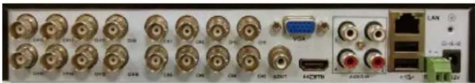
HDVR-835 Rear Panel
natural_image
Front panel of an electronic device showing ports, connectors, and a USB port (no readable text or symbols)| Connector Description | |
| V1-V8 | Composite video signal (CVBS) input interface |
| A1-A4 | The input interface of the audio signal |
| A-OUT/V-OUT | The output interface of the audio/video signal |
| LAN The network interface of RJ45 | |
| HDMI The output interface of the HDMI video signal | |
| VGA The output interface of the VGA video signal | |
| 12V DC | 12V 2A DC power |
| 485+/485- | The interface of the alarm input, the alarm output and RS-485 |
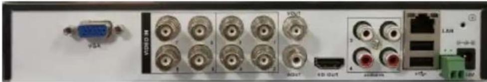
HDVR-1635 Rear Panel
natural_image
Front panel of an electronic device showing multiple gold connectors, a USB port, and network ports (no readable text or symbols)| Connector Description | |
| V1-V16 | Composite video signal (CVBS) input interface |
| A1-A4 | The input interface of the audio signal |
| A-OUT The output interface of the audio signal | |
| LAN The network interface of RJ45 | |
| HDMI The output interface of the HDMI video signal | |
| VGA The output interface of the VGA video signal | |
| 12V DC | 12V DC, 2A |
| 485+/485- | The interface of the alarm input, the alarm output and RS-485 |
2.2 Hardware Installation
2.2.1 Installing Hard Disk
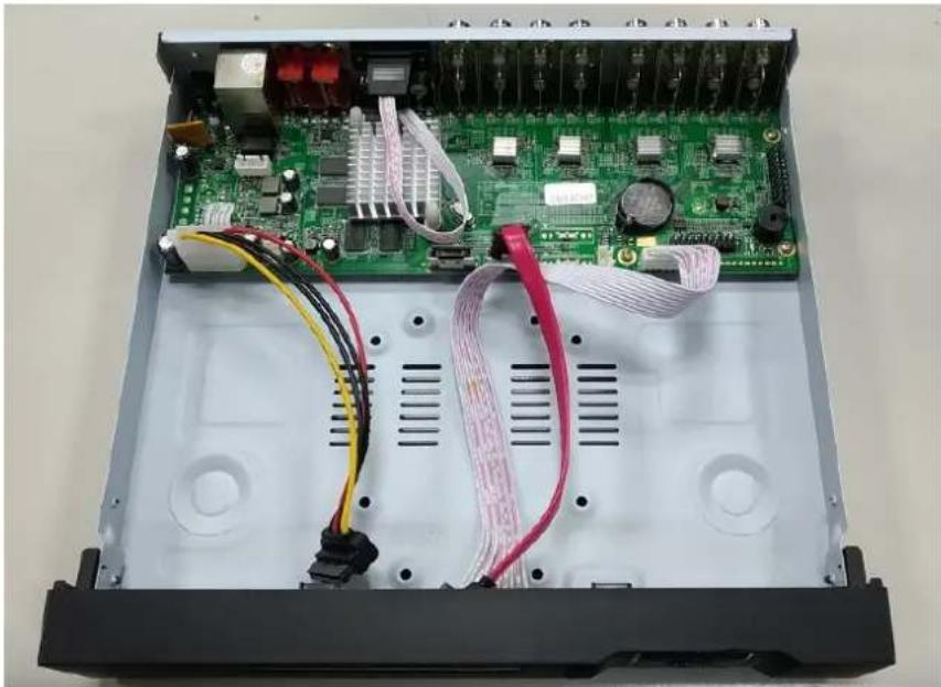
- Remove the upper case.
natural_image
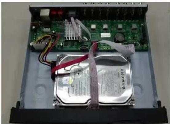
Interior view of an electronic device showing a green circuit board with visible wiring and connectors (no text or symbols)- Plug the HDD power cable and SATA cable into the slots of the PCBA board and the HDD, respectively, making sure the connections are well done.

natural_image
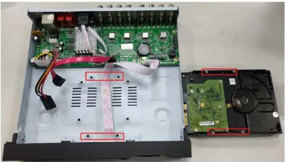
Close-up of an open electronic device showing a green circuit board, red and yellow wires, and a metallic hard disk (no visible text or symbols)- Please align the screw holes on the HDD with those on the HDVR case and secure them with the given screws.
natural_image
Interior view of an open computer drive showing internal components including a green circuit board, hard drives, and a black hard drive (no text or symbols visible)- After the HDD is secured, it should look like the one in the pictures (front and back) below:
natural_image
Internal view of an electronic device showing a circuit board, CPU socket, and cable wrapped around it (no visible text or symbols)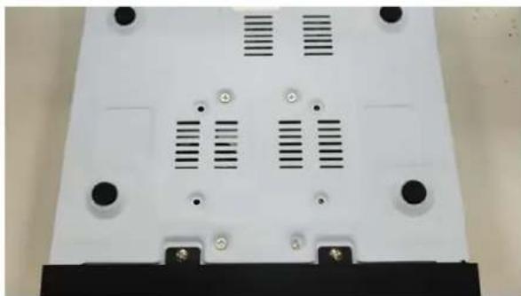
natural_image
Top-down view of a white plastic electronic device casing with ventilation slots and mounting points (no text or symbols visible)Chapter 3. Connecting to the HDVR
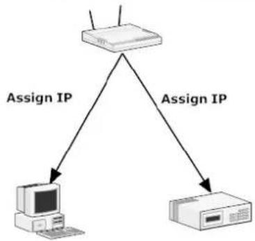
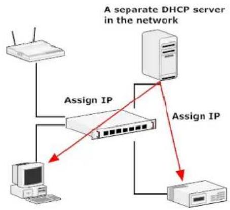
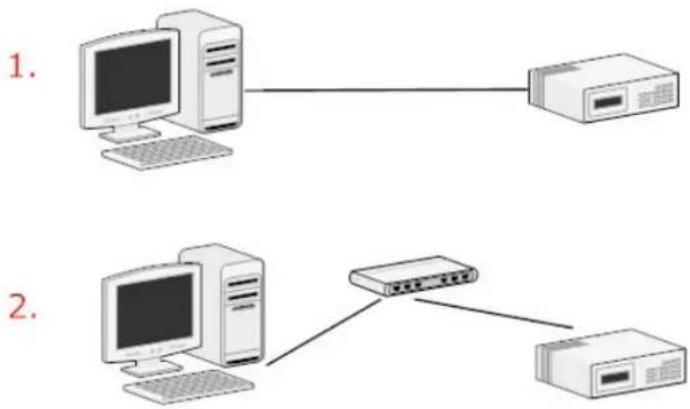
There are various ways you can connect to the HDVR and below are the suggested methods for different network setups:
The HDVR is placed in a network with a DHCP server: Connect to the HDVR by using "HDVR Search Tool" Utility.
The HDVR is placed in a network without DHCP server (or you are connecting to it directly): Access HDVR with its default IP (192.168.0.20).
3.1 Using Search Tool Utility
If the HDVR is placed in a corporate network or a local area network where a DHCP server is already presented, please install the "Search Tool" utility from the PLANET website.
- Network gateway as the DHCP server
flowchart
graph TD
    A["Server"] -->|Assign IP| B["Computer"]
    A -->|Assign IP| C["Printer"]
flowchart
graph TD
    A["Router"] -->|Assign IP| B["Switch"]
    B -->|Assign IP| C["Computer"]
    B --> D["A separate DHCP server in the network"]
    D -->|Assign IP| C
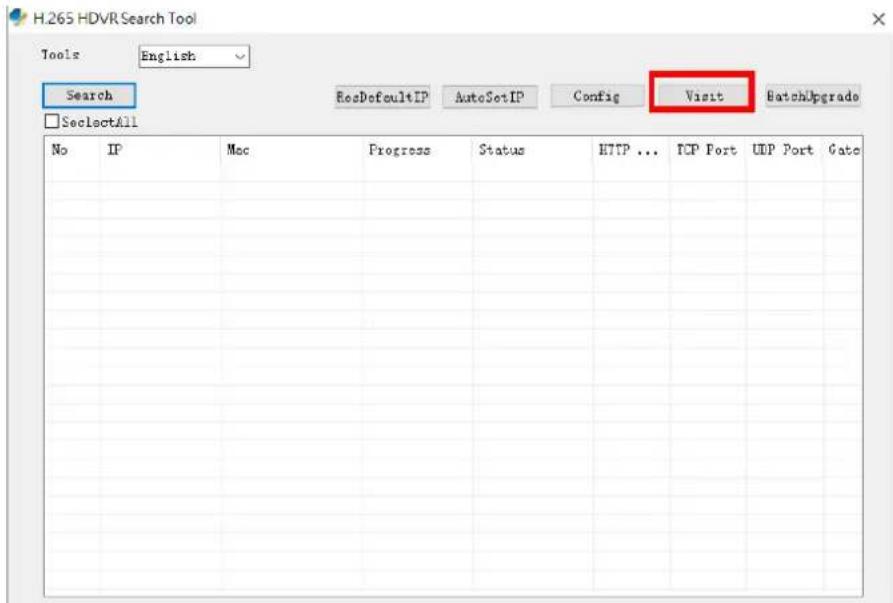
To begin, execute the "Search Tool" utility.
Next, press the "Search" button to find the HDVR.
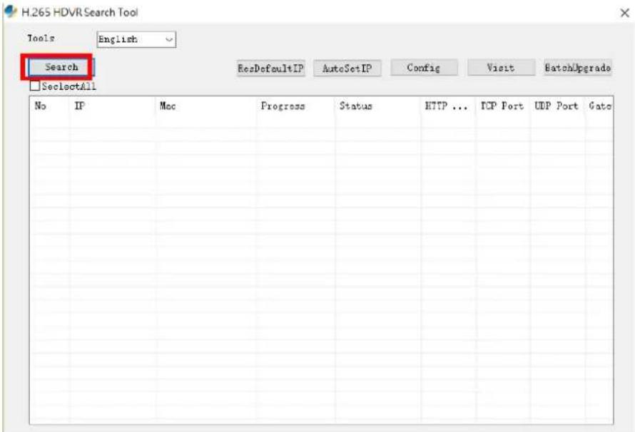
The HDVR should be located and its IP address should be displayed. Select the HDVR and click on "Visit"; the program should automatically access the HDVR's web administration page from your default browser.
3.2 Accessing HDVR with its default IP address
The HDVR comes with a pre-configured static IP address "192.168.0.20". However, it is only used when there is no DHCP server presented in the network. Connect the HDVR and PC to your switch or hub, or connect the PC directly to the HDVR using a crossover Cat5 Ethernet cable.
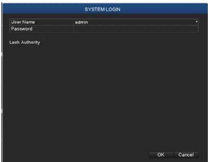
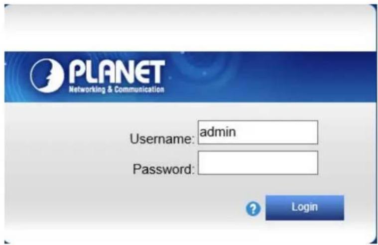
You can select utility or type the IP address to connect with HDVR directly. After the login, a window appears, prompting for the HDVR's username and password. Enter "admin" for both default username and password, and then click "OK" to enter the system.

Login page of local display

Login page of Web
Chapter 4. Basic Operation
This chapter provides setup instructions of the HDVR local display Interface.
4.1 Main/Live Viewing

The main/live view is the first interface displayed once you access the HDVR through local display. It displays the live video of all cameras added to the HDVR and the above patterns chosen by the user. The interface has many functions explained below.
4.2 Preview
You can right-click mouse to switch between the windows. The system date, time and channel name are shown in each viewing window. The surveillance video and alarm statuses are shown in each window.
| 1 |  | Recording status | 3 |  | Video loss |
| 2 |  | Motion detection | 4 |  | Speaker Disabled |
| 5 |  | Internet Connected | 5 |  | Internet Disconnected |
Table 4.1 Preview Icon
4.3 Desktop Shortcut Menu
In preview mode, you can right-click mouse to get a desktop shortcut menu as shown below. The menu includes Main Menu, Guide, PTZ Control, Coaxial Control, Preview Signal, Color Setting, Play Back, Record Mode, Channel Type and Camera Manage.
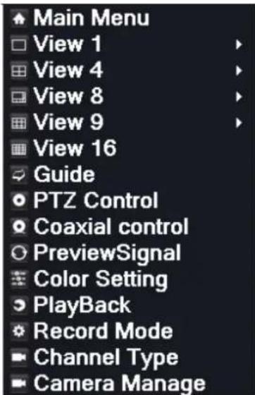
Picture 4.2 Shortcut Menu
4.3.1 Main Menu
The system main menu is shown below after login.
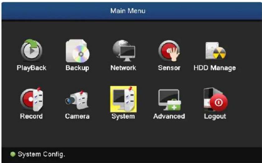
Picture 4.3 Main Menu
4.3.2 Window Switch
Previewing in single window, four windows, eight windows, nine windows or sixteen windows is up to your choice.

Note
Different video input numbers have different switchable previewed pictures.
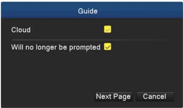
4.3.3 Guide
Select "Cloud" to enable cloud service function.
Select "Will no longer be prompted", HDVR will not display Guide interface after boot.
Click "Next Page" button to enter next option.
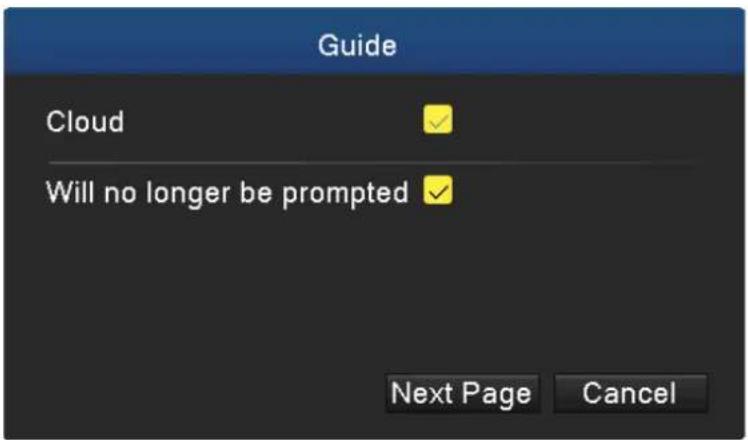
Picture 4.4 Guide
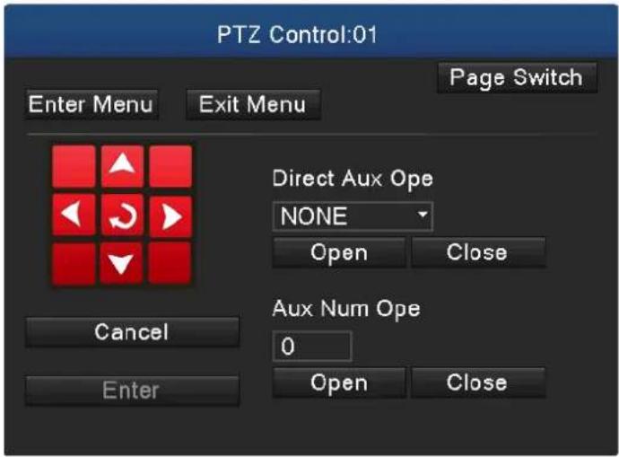
4.3.4 PTZ Control
PTZ control is a little different between analog mode and full digital mode.
1) Digital channel – the digital channel needs to link PTZ; the remote device should connect with PTZ with protocol correctly set also.
2) Analog channel – Only when the device is connecting with PTZ and configuring protocol correctly is OK.
Operation interface is shown below. The functions include PTZ direction control, speed, zoom, focus, iris, preset, tour, auto pan and so on.

Note
- When Decoder A (B) line connects with HDVR A (B) line, the connection is right.
- Click [main menu] > [system configuration] > [PTZ configuration] to set the PTZ parameters.
- The PTZ functions are decided by the PTZ protocols.
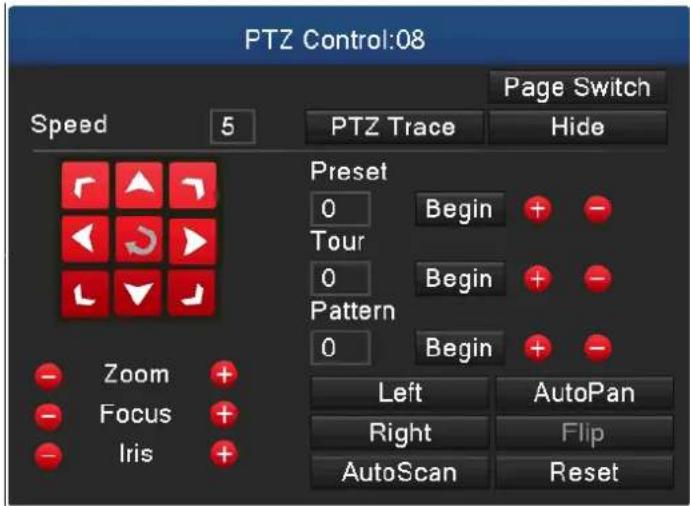
Picture 4.5 PTZ Setup
| Speed | Set the PTZ rotation range. Default range: 1 ~ 8. |
| Zoom | Click the [IMAGE] / [IMAGE] button to adjust the focal length of the camera. |
| Focus | Click the [IMAGE] / [IMAGE] button to adjust the focus of the camera. |
| Iris | Click the [IMAGE] / [IMAGE] button to adjust the iris of the camera. |
| Preset | Click the [IMAGE] / [IMAGE] button to add or delete preset points. |
| Hide | The current interface will be temporarily hidden after clicking it. |
| Direction Control | Control the PTZ rotation. Control of 8 directions is supported.(4 directions on Front panel is supported) |
| Page Switch | Switch between different pages. |
4.3.5 Coaxial Control
Click "Coaxial Control" to enter coaxial control interface.
Picture 4.6 Coaxial Control Setup
4.3.6 Preview Signal
Click "Preview Signal" to enter preview signal selection interface, and then set43 to AHD/TVI/CVI signal preview.
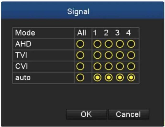
Picture 4.7 Signal
4.3.7 Color Setting
Color setting is only applied for hybrid /full analog mode and can be configured in analog channel. You can adjust the selective image parameters according to your requirement (current channel for single window display and cursor place for multi-window display). Through desktop shortcut menu, you are able to enter the interface. The image parameters include tonality, brightness, contrast and saturation. Besides, you can set different parameters at different time sections.
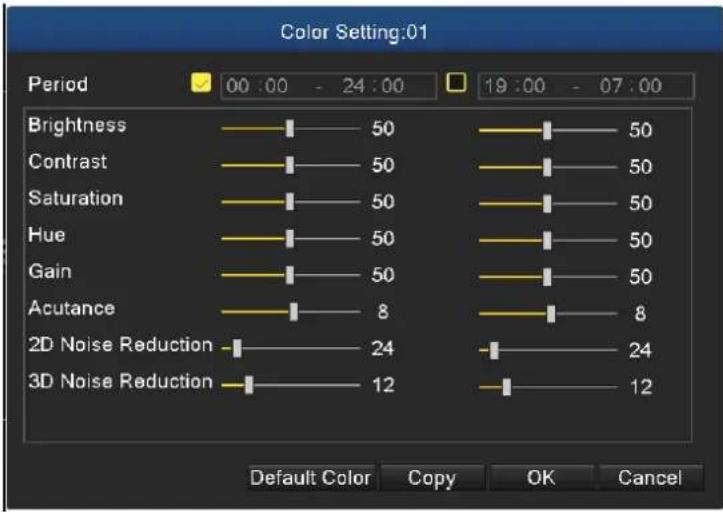
Picture 4.8 Color Setting
4.3.8 Playback
There are two methods for you to exceed playback.
- In the desktop shortcut menu.
- Main menu→Playback

Note
The hard disk that saves the video files must be set as read-write or read-only state.
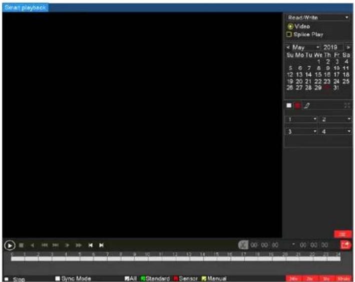
Picture 4.9 Video Playback
| Key | Function | Key | Function | |
  | Play/Pause |  | Backward play | |
 | Slow forward |  | Fast forward | |
 | Previous frame |  | Next frame | |
 | Previous file |  | Next file | |
 | Full screen |  | Stop | |
Table 4.10 Playback Control Button
Operation tips: Show function of the key that cursor placed.

Play frame by frame; the playback status should be paused first.
Special functions:
Accurate playback: Select time (h/m/s) in the time column and then click the play

button. The system can operate accurate playback according to searching time.
Local zoom: When the system is in the single-window, full-screen playback mode, you can drag your mouse on the screen to select a section and then left-click mouse to realize local zoom. You can right-click mouse to exit.
4.3.9 Record
Please check the current channel status; "o" means it is not in the recording status, and "●" means it is in the recording status. You can use desktop shortcut menu or click [main menu] > [recording function] > [recording conf.] to enter the recording control interface.
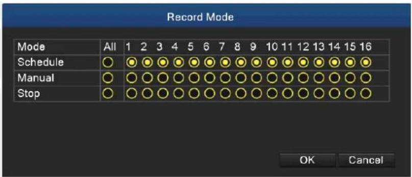
Picture 4.11 Record Mode
| Schedule | Record according to configuration. |
| Manual | Click the button to start recording of selected channel in any state. |
| Stop | Click the button to stop recording of selected channel in any state. |
4.3.10 Channel Type
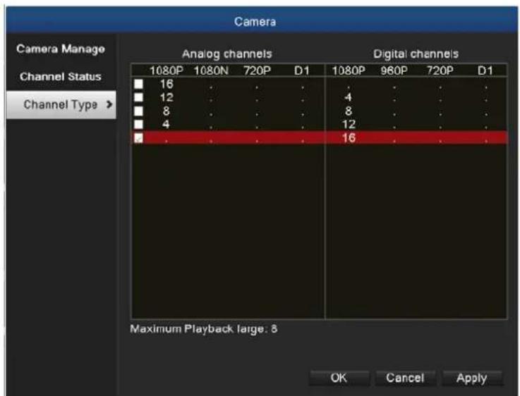
Picture 4.12 Channel Type

Note
In this series of product, the HDVR provides full analog channel mode, hybrid mode and full digital mode in channel type. Different models have different channel modes. User can shift the mode freely if necessary.
4.3.11 Camera Management
Picture 4.13 Camera Management
Chapter 5. Main Menu
5.1 Main Menu Navigation
| Main Menu | Sub Menu | Function |
| Record Config | Set the recording configuration, recording type and recording time section | |
| Playback Config | Set recording search, recording play and video file storage | |
| Backup Config | Detect backup device, format device, back up the selective files | |
| Network | Config | Set the DHCP, IP address, subnet mask, gateway, DNS and port numbers |
| DDNS | Enable/disable DDNS, set DDNS type such as PLANETDDNS, EasyDDNS | |
| UPNP Enable/disable UPNP | ||
| Set SMTP server to send alarm message when event is triggered | ||
| Cloud | Download and install app for mobile to view image remotely via cloud | |
| Net Service | Provide PPPoE, RTSP, IP Filter, FTP, NTP and Dropbox settings | |
| Sensor | Motion detection | Set motion detection alarm for selected input channel. The related parameters include motion sensitivity, motion area, time section, motion detection interval, message, post recording, PTZ, patrol, buzz, email and FTP upload |
| Video blind | Set camera mask for selected alarm channel. The related parameters include time period, message, post recording, PTZ, patrol, buzz, email and FTP upload | |
| Video loss | Set video loss alarm for selected input channel. The related parameters include time period, message, post recording, PTZ, patrol, buzz, email and FTP upload | |
| Abnormality | System events include no storage, storage error, limited storage space, network disconnection and IP Conflict. Event action parameters: message and buzzer. | |
| System configuration | General configuration | Set system time, data format, language and hard disk in action when it is full and comes with machine number, video standard, auto logout, etc. |
| Encode configuration | Set main (extra) coding parameters: code mode, resolving ability, frame rate, code stream control, image quality type, code stream value, and frame between value and video/audio. | |
| GUI display | Set channel name, time display, record status, alarm status, deflicking, transparency and resolution. | |
| PTZ configuration | Set channel, PTZ protocol, address, baud rate, date bit, stop bit and parity | |
| Tour | Set patrol mode and interval time | |
| Output adjust | Adjust different deflates, display settings, brightness, contrast, saturation and hue parameters. | |
| Restore | Factory default settings for general setup, encode setup, recording setup, alarm setup, network setup, network service, output settings, account and RS232 | |
| RS232 | Set baud rate, data bits, stop bits and parity parameters for different functions | |
| Account | Modify user, group or password. Add user or group. Delete user or group. | |
| Advanced | Version | Display firmware, MAC address information, etc. |
| Log | Search and clear log information according to log types | |
| BPS Display | code stream information | |
| Online user | Break the connection of the existing login user. After breaking connection, the account is locked until booting up again. | |
| Device Info | Device configuration and information | |
| Upgrade | Upgrade firmware with external device (like USB) | |
| Automatic Maintenance | Settings for automatic reboot system and auto-delete old files. | |
| Import/Export | Export the device's log or configuration to external device (like USB flash disk); input the configuration with external device (like USB flash disk). | |
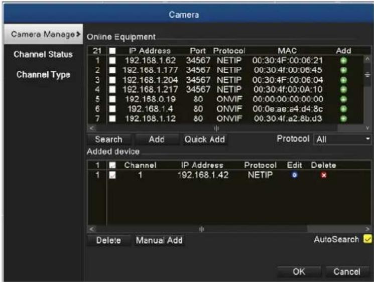
| Camera | Camera Management | Search, add, delete IP cameras and display whatever devices has been added |
| Channel Status | Display resolution, frame rate and connection status information | |
| Channel Type | Set digital mode, analog mode or hybrid mode. Before connecting cameras, it is necessary to set this function first. | |
| HDD Management | Config | Set appointed hard disk as read-write disk, read-only disc, format hard disk, resume date and so on |
| Logout | Config | Logout, shut down or reboot |
5.2 Record
Operations related to record.
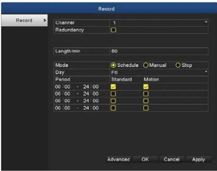
5.2.1 Record Configuration
Set the recording parameters in the surveillance channel. The system sets 24 hours consecutive recording in the first startup. You can enter [main menu] > [recording function] > [record configuration] to set.

Note
There is at least one read-write hard disk (refer to chapter 5.8.1).
Picture 5.1 Record Configuration
| Channel | Choose the corresponding channel number to set the channel.Choose the all option to set the entire channels. |
| Redundancy | Choose the redundancy function option to implement the file double backup function. Double backup is writing the video files in two hard disks. When you do the double backup, make sure that there are two hard disks installed. One is read-write disk and the other is redundant disk. (refer to 5.8.1) |
| Length | Set the time length of each video file. 60 minutes is default value. |
| Record Mode | Schedule: Record according to the set video type (common, detection and alarm) and time section.Manual: Click the button and the channel is recording no matter what state it is in.Stop: Click the stop button and the channel stops recording no matter what state it is in. |
| Day | Select the day you want to record. The options include Sunday/Monday/Tuesday/Wednesday/Thursday/Friday/Saturday and All. |
| Period | Set the time section of common recording, The recording will start only in the set range. Meanwhile, the motion recording also can be set in this function. |

Refer to chapter 5.5 to set corresponding sensor function.
5.3 Playback
Refer to chapter 4.3.8.
5.4 Backup
You can back up the video files to external storage through setup. The storage must be installed before the file backup. If the backup is finished, the video can be displayed individually.
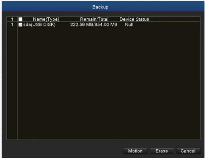
Picture 5.2 Backup
| Motion | Detect the storage connected with the HDVR such as hard disk or universal disk. |
| Erase | Click the button and then the external USB storage will be formatted. |
![Backup Channel 1 File Type All Type Read/Write Start Time 2019 - 05 - 30 00 : 00 : 00 End Time 2019 - 05 - 30 16 : 00 : 51 Backup format AVI Remove Search 2 Channel File Name Length 1 01 2019-05-30/16.00.31-16.00.34[R].h265 44.00 KB 2 01 2019-05-30/16.00.36-16.00.48[R].h265 64.00 KB Remaining109.00 KB/222.48 MB Motion Start Burning](/content/2026/05/1044032/images/76a56c2779a04e51b3af9868ecef80ed1fbb73e532f60a31505d75ed4c5aaac7.jpg)
Picture 5.3 Backup
| Remove | Clear the file information. |
| Search | Show the file information satisfying the set file attributes. |
| Backup Format | Configure the backup file format based on requirement. H.26X, AVI or MP4 format can be selected. |
| Start | Click the start button to start the backup |
| Burning | The file will be burned synchronously after clicking it. |
| Stop | Click the stop button to stop the backup. |
5.5 Sensor Function
Sensor function includes motion detection, video blind, video loss and abnormality.
5.5.1 Motion Detection
When system detects the motion signal that reaches the set sensitivity, the motion detection alarm is on and the linkage function is turned on. The details are shown below.
Digital channel: It not only enables motion detection function at the local side, but also enables the remote device that is connected. When remote device detects motion movement, the local side will start alarm recording, provided this function is not enabled.
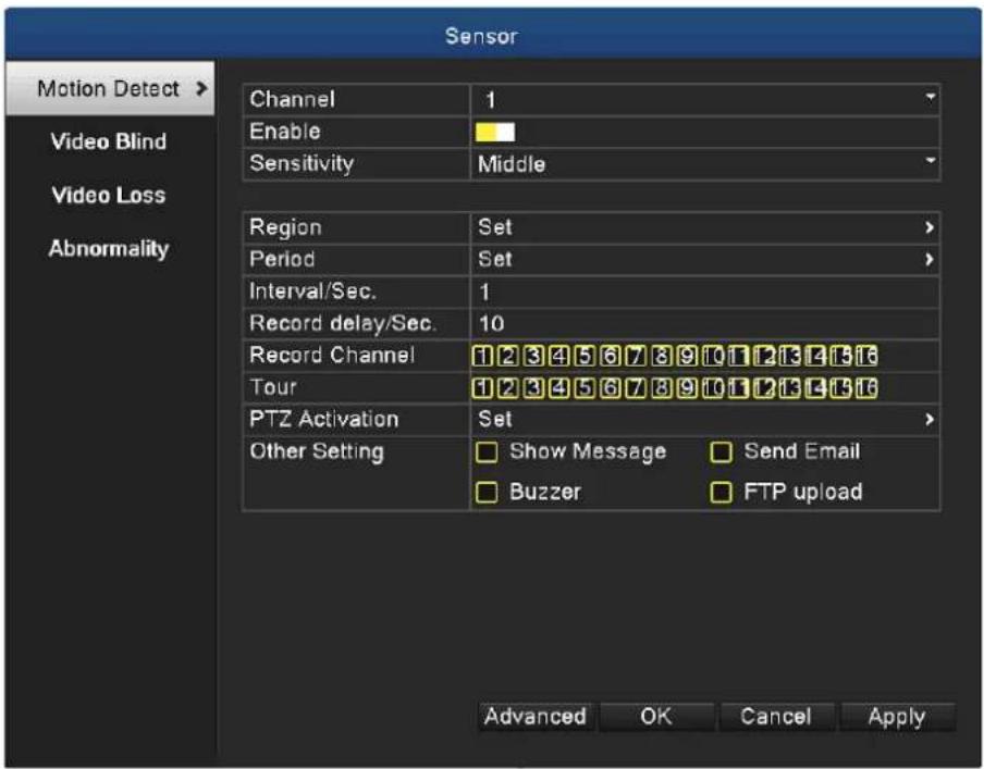
Picture 5.4 Motion Detection
| Channel | Choose the set motion detection channel. |
| Enable | The motion detection function is on when the box is checked. |
| Sensitivity | Six options are provided in the sensitivity. |
| Region | Click the set button to enter the set area. The area is divided into PAL 16X12. Red block means the motion is being detected in the defensive area. White block means the unfenced area. You can set the area as follows: Drag the mouse and draw the area. Default: all selected blocks are detection areas. |
| Period | Trigger the motion detection signal in the time section. You can set by week or set uniformly. Each day is divided into four time sections. |
| Interval/Sec. | Only one alarm signal is turned on even there are several motion detection signals in the set interval. |
| Record delay/Sec. | Delay a few moments and stop when the alarm state is turned off. The default is 10 seconds. |
| Record Channel | Choose the recording channel (multiple options supported). Trigger the video signal when the alarm is turned on. |
| Tour | It means that the selected channel is single window alternate patrol preview. The interval is set in the [Main Menu]> [System] >[Tour]. |

natural_image
Grid pattern with a central white square and a small green rectangle, no text or symbols present.Picture 5.5 Region
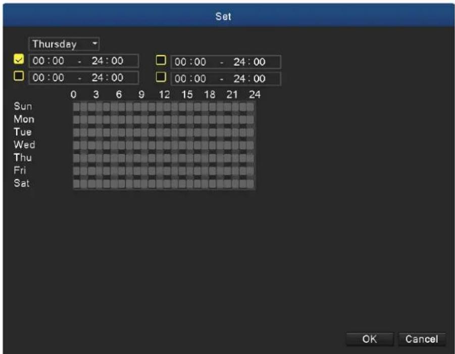
Picture 5.6 Set the Time Section
PTZ Activation: Set the PTZ activation when the alarm is turned on.
In hybrid mode, PTZ links to the related PTZ information of analog channel. While in digital channel model, PTZ links to the related PTZ information on the remote device which is connected.

Note
To link PTZ, you can leave for [Shortcut menu]->[PTZ control] to set preset point, cruise between points and interval time, etc.
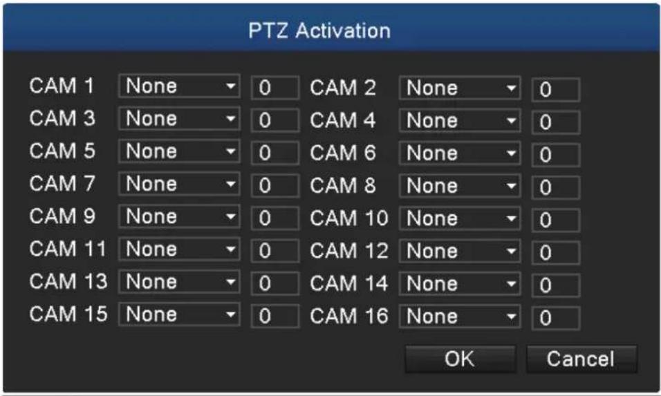
Picture 5.7 PTZ Activation in Hybrid Mode
Show message: Pop-up the dialog box of alarm information on the screen of the local host computer.
Send email: It means sending an email to user when the alarm is turned on.

Note
Set in the Email function and make a mail testing first.
FTP upload: When it is enabled, the video and picture of the related record channel and snapshot channel will be uploaded to an assigned position.

Note
FTP upload needs to be set at Netservice interface.
Buzz: When alarm happens, the device will send out a buzz.
5.5.2 Video Blind
When the video image is influenced by the environment such as poor brightness or reaching the set sensitivity parameter, the camera mask function and the linkage function are turned on. The details are shown below.
Digital channel: It not only enables video blind function at the local side, but also enables the remote device that is connected. When the remote device is with video blind, the local side will start alarm recording, otherwise this function is not enabled.
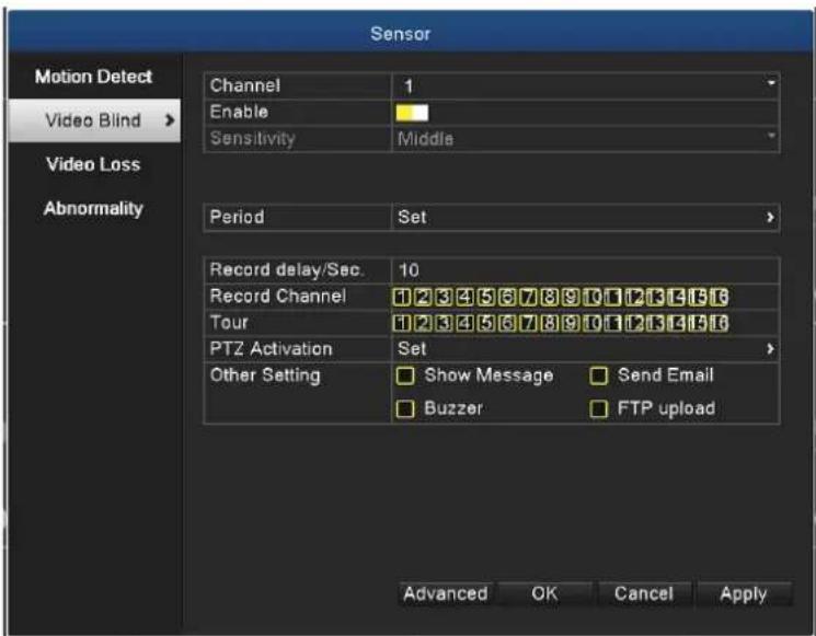
Picture 5.8 Video Blind
Set method: Refer to Motion Detection in Chapter 5.5.1.
5.5.3 Video Loss
When the equipment cannot obtain the channel video signal, the video loss alarm and the linkage function are turned on. The details are shown below.
Digital channel: It not only enables video loss function at the local side, but also enables the remote device that is connected. When remote device is with video loss, the local side will start alarm recording, otherwise this function is not enabled.
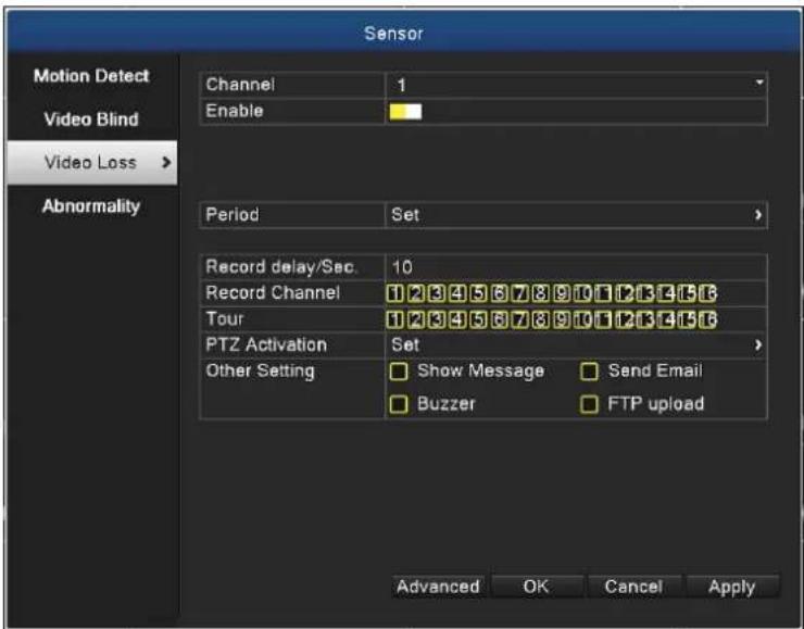
Picture 5.9 Video Loss
Set method: refer to Motion Detection in Chapter 5.5.1.
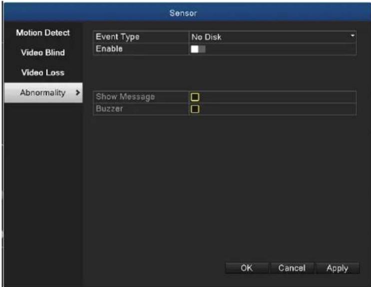
5.5.4 Abnormality
Analyzing and inspecting the current software and hardware of the device. When some abnormal events happen, the device will take an action immediately, such as show message and buzzer.
Picture 5.10 Abnormal
| Event Type | Select abnormality you want to inspect. |
| Enable | Select it to make sure abnormal function workable |
| Show Message | Automatically alarm cue dialog box pops out of the main screen |
| Buzzer | Device will have one long “di” sound while alarm is happening |
5.6 System Setup
In system setting, the functions contain General, Encode, GUI display, PTZ configure/RS485 device, Tour, Output Adjust, Restore, RS232, and Account.
5.6.1 General
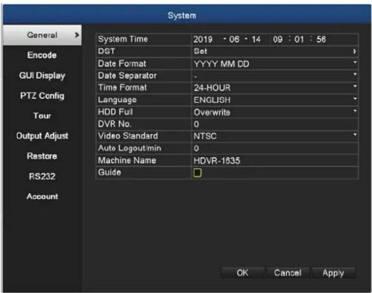
Picture 5.11 General Setup
| System Time | Set the system date and time. |
| DST | Daylight saving time |
| Date Format | Choose the date format: YMD, MDY, DMY. |
| Date Separator | Choose list separator of the date format. |
| Time Format | Choose time format: 24-hour or 12-hour. |
| Language | Support multiple languages up to 28. |
| HDD Full | Stop recording: Stop recording when the hard disk is full.Overwrite: Cover the earliest recording files and continue recording when the hard disk is full |
| DVR No. | Only when the address button in the remote controller and the corresponding DVR number are matched, the remote operation is valid. |
| Video Standard | PAL or NTSC. |
| Auto Logout | Set the latency time in 0-60. 0 means no latency time. |
| Machine Name | Can set the device's name. |
| Guide | Enable or disable Guide page |
Picture 5.12 Guide
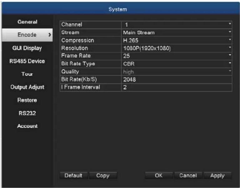
5.6.2 Encode Setup
HDVR provides encode setting in hybrid mode or full analog mode. The encode setting is for analog channel only.
Set the video/audio code parameter: video file, remote monitoring and so on. Set every main
stream parameter in the left part, and set the extra stream parameter in the right part.

Note
Extra stream introduces video compression technique which applies for multi-channel playback simultaneously, dial-up multi-channel real-time monitor under poor bandwidth, or mobile monitor, and so on.
Picture 5.13 Digital Encode Setup
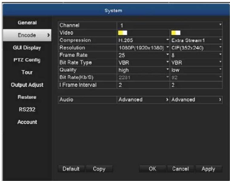
Picture 5.14 Hybrid/ Analog Encode Setup
| Channel | Choose the channel number. |
| Compression | Standard H.264/H.265/H.265+ main profile and extra stream. |
| Resolution | Resolution type: 1080P/720P/960H/VGA/D1/CIF. |
| Frame Rate | 1 frame/s~25 frame/s |
| Bit Rate Type | You can choose limited code stream (CBR) or variable code stream (VBR). When you choose the variable code stream, there are six image quality options. Under the limited code stream, you can choose the code stream manually. |
| Bit Rate | Set the code stream value to modify the image quality. The larger code stream values the better image quality.4563kbsp/3422kbps/2281kbps/1710kbps/1140kbps/570kbps |
| Frame Interval | Choose the range from 2 to 20s. |
| Video & Audio | When the icons are all in reverse display, the video file is video and audio multiplex stream. |
| Extra Stream Setting | Extra stream: It is used for client side monitoring and mobile monitoring.Channel title: Select channel title and then choose whether it needs to enable video and audio. The resolution, frame rate and bit rate type settings are the same as main stream. |
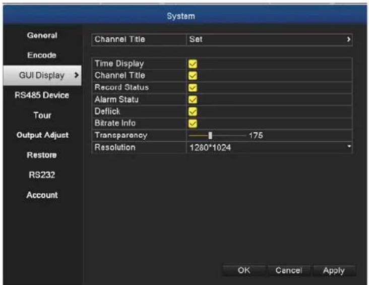
5.6.3 GUI Display
Configure the video output parameters including the monitor output mode and encode output mode.
Monitor output: In the local preview mode, it includes channel title, time display, channel display, record status, alarm status, transparency and region cover information.
Encode output: In the network surveillance and video file mode, it includes channel title, time display, channel display, record status, alarm status, transparency and region cover information.
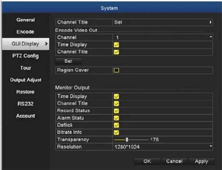
The GUI Display Page in Hybrid Mode and All Analog Mode
Picture 5.15 Output Mode
The GUI Display Page in Full Digital Channel Output Mode
Picture 5.16 Output Mode
| Channel Title | Click the channel name modify button and enter the channel name menu. The 16 Chinese characters and 25 letters are supported. |
| Time Display | Display the system data and time in the surveillance window. |
| Channel Display | Display the system channel number in the surveillance window. |
| Record Status | Display the system recording status in the surveillance window. |
| Alarm Status | Display the system alarm status in the surveillance window. |
| Transparency | Choose the background image transparency. The range is 128~255. |
| Resolution | Set display resolution. |
| Channel | Choose the set code output channel number. |
| Region Cover | Click the cover area button and enter the corresponding channel window. You can cover the arbitrary using mouse. (Black region is for output) |
| Time Display and Channel Display | Set the display position of channel title and time title. |

Note
The channel number, region cover, time title and channel title settings exist in output mode only when the device is in hybrid (HVR) mode or full analog (DVR) mode.
5.6.4 PTZ/RS485 Device
When system is in hybrid mode or full analog mode, PTZ device and RS485 device are listed on the PTZ configure page.
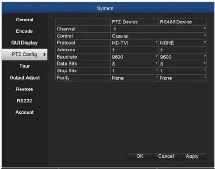
Picture 5.17 PTZ Configuration
| Channel | Choose input channel of dome camera. | |
| Protocol | Choose the corresponding dome protocol. (PELCOD as an example) | |
| Address | Set as the corresponding dome address. Default: 1. | The address must be consistent with the dome address |
| Baud Rate | Choose the corresponding dome baud rate length. You can control the PTZ and vidicon. Default: 9600. | |
| Data bits | Include 5-8 options. Default: 8. | |
| Stop Bits | Include 2 options. Default: 1. | |
| Parity | Include odd check, even check, mark check, space check. Default: none. | |
When in full digital mode, only RS485 device is shown below.
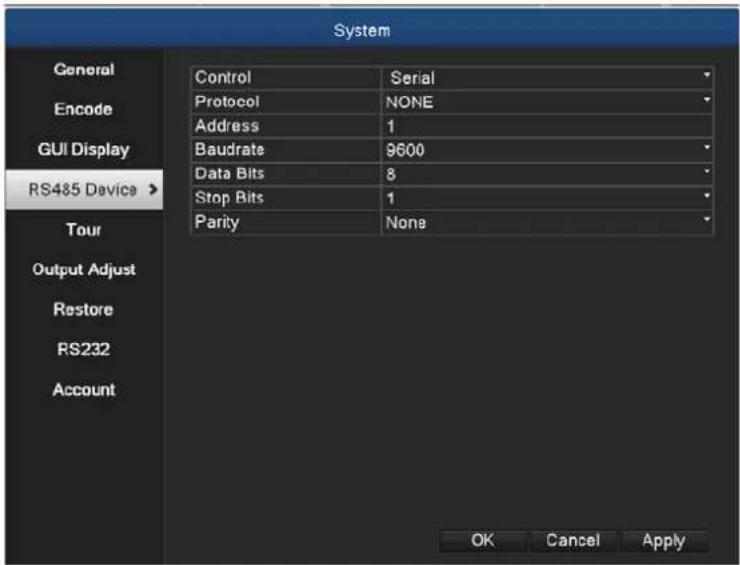
Picture 5.18 RS485 Device
| Protocol | Choose related protocol of brand model (e.g. Vista) |
| Address | Set with corresponding address, default is 1 |
| Baud Rate | Choose baud rate that related device uses; default is 9600 |
| Data Bits | Include 5-8 options, default is 8 |
| Stop Bits | Include 2 options, default is 1 |
| Parity | Include odd check, even check, mark check, space checkDefault: none |

Note
When analog channel exists, PTZ and RS485 will be shown in PTZ setting. If device is in digital mode, it will show RS485 only.
5.6.5 Tour
Set the patrol display. The tour mode is enabled when box is checked. You can choose the single-view, four-view or nine-view of single mode tour or hybrid mode tour.
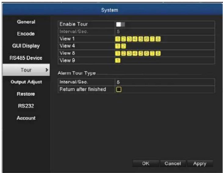
Picture 5.19 Tour Configure
| MD Interval | Set the patrol switch interval. The set range is 5-120 seconds. |
| Alarm Tour | Set the interval to shift alarm tour; range is 5-120 seconds.Choose return when alarm ends. When alarm is linking to tour,the system will auto shift to nine-view after alarm is finished. |
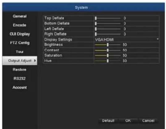
5.6.6 Output Adjust
In hybrid mode, the output adjust function supports black vertical and black horizontal adjustment; in full digital mode, the function does not support the adjustment below. The function allows you to adjust TV output area parameters. You can go to the setup interface via desktop shortcut menu or enter [main menu] > [system] > [output adjust].
Hybrid Mode Full Digital Mode
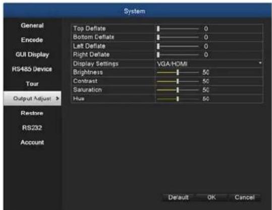
Picture 5.20 Output Adjust

Note
The black vertical and horizontal lines at output adjust can affect analog channel in the hybrid mode.
5.6.7 Restore
Reset the HDVR's settings to their factory default values. You can choose the items according to your requirements.
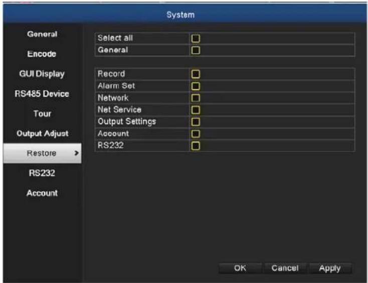
Picture 5.21 Restoring to Default
5.6.8 RS232
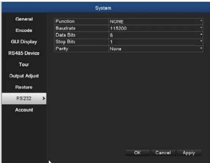
Picture 5.22 Serial Port Setting
| Function | Common serial port is used to debug and update program or set up specific serial port. |
| Baud Rate | Choose the corresponding baud rate length. |
| Data Bits | Include 5-8 options. |
| Stop Bits | Include 2 options. |
| Parity | Include odd, even, mark, space, default is none. |
5.6.9 Account
Manage the user purview.
- The character length is 8 bytes at most for the following user and user team name. The blank ahead or behind the character string is invalid. The middle blank in the character string is valid. Legal characters include letter, number, underline, subtraction sign, and dot.
- There is no limit in the user and user group. You can add or delete the user group according to user definition. The factory setup includes user and admin. You can set the team as you wish. The user can appoint the purview in the group.
- The user management includes group and user. The group and user name cannot be the same. Each user only belongs to one group.
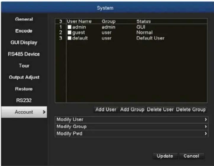
Picture 5.23 Account Management
Modify User: Modify the existing user attribute.
Modify Group: Modify the existing team attribute.
Modify Password: Modify the user password. You can set 1-6 bit password. The blank ahead or behind the character string is invalid. The middle blank in the character string is valid.

Note
The user who possesses the user control purview can modify his/her own or other user's password.
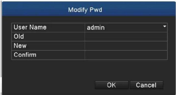
Picture 5.24 Modifying Password
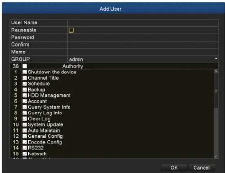
Add User: Add a user in the group and set the user purview. Enter the menu interface and input the user name and password. Choose the team and choose whether cover using the user. Cover using means that the account can be used by multiple users at the same time. Once the team is chosen, the user purview is the subclass of the team. We recommend that the common user's purview is lower than the advanced user.
Picture 5.25 Adding User
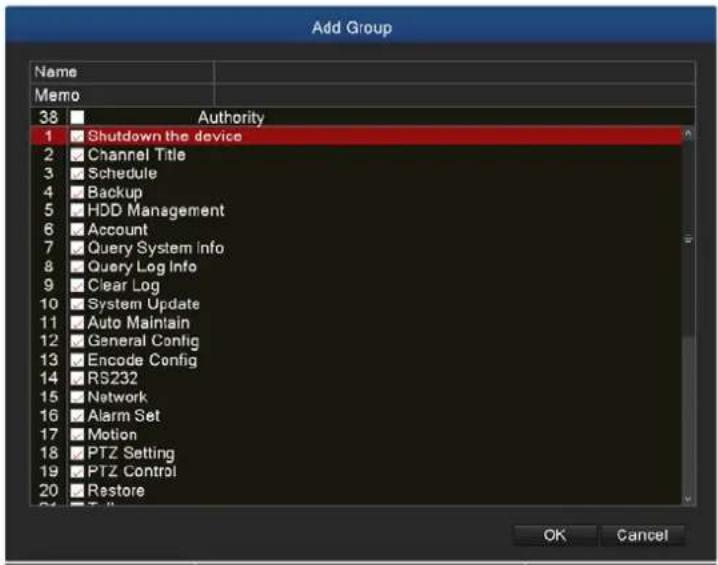
Add Group: Add a user group and set the purview. There are 33 different purviews: shut down the equipment, real-time surveillance, playback, record setting, video backup, etc.
Picture 5.26 Adding Group
Delete User: Delete the current user. Choose the user and click the delete user button.
Delete Group: Delete the current group. Choose the group and click the delete group button.
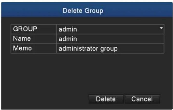
Picture 5.27 Delete Group
5.7 Advanced
Manage tools menu provides Version, Log, BPS, Online User, Device Info, Upgrade, Auto Maintain and Import/Export functions.
5.7.1 Version
Display the basic information such as hardware information, software version, issue date, serial number and NAT status.
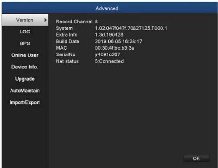
Picture 5.28 Version Information
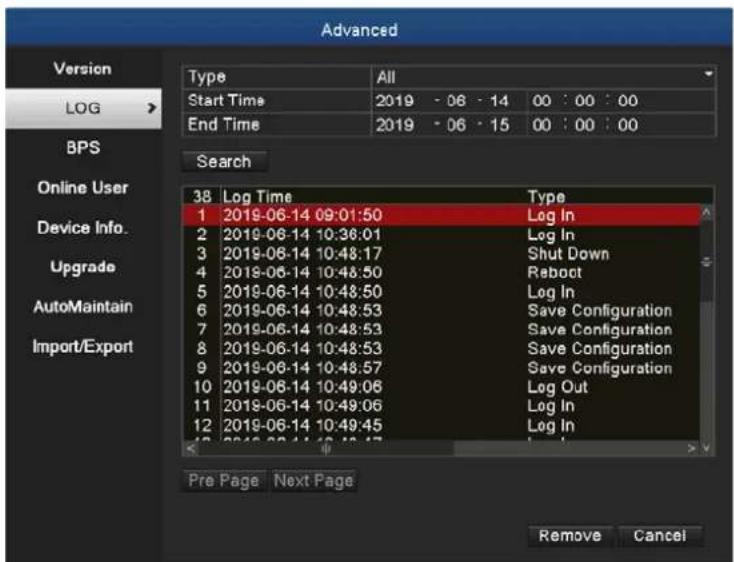
5.7.2 Log
Log information includes system operation, configuration operation, data management, alarm affair, recording operation, user management, file management, etc. You can set the time section and click the Search button to look for logs. The log information will be displayed as the following list (one page lists 128 items). Next, you can press the Pre Page or Next Page button to browse and press the Clear button to clear all log information.
Picture 5.29 Log Information
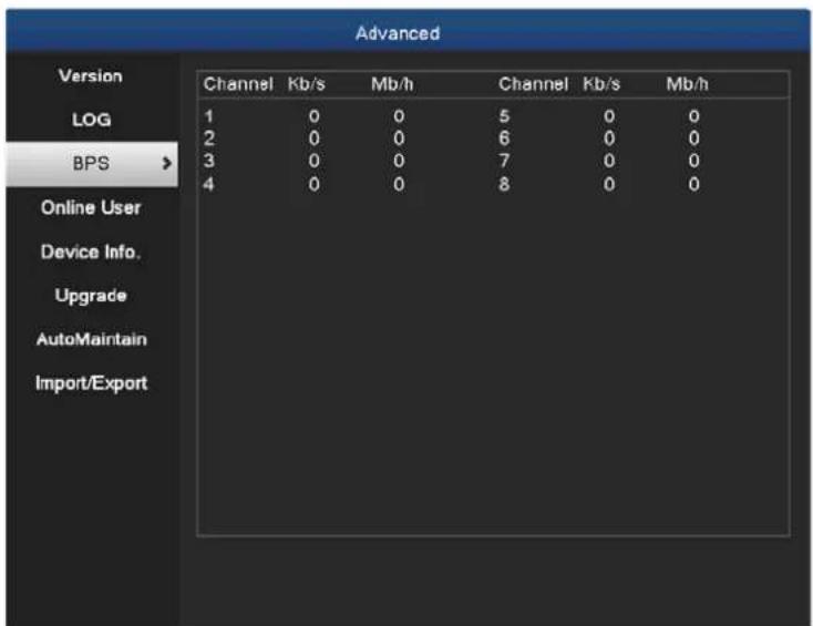
5.7.3 BPS
Display the code stream (Kb/S) and hard disk capability (MB/H) in real time. It displays as the wave sketch map.
Picture 5.30 BPS
5.7.4 Online User
Check the information of network user that is connected with local device. Tick the selected user to break up connection, (make √ at the box), and then the user will be frozen after connection is stopped. It will not log in until device reboots.
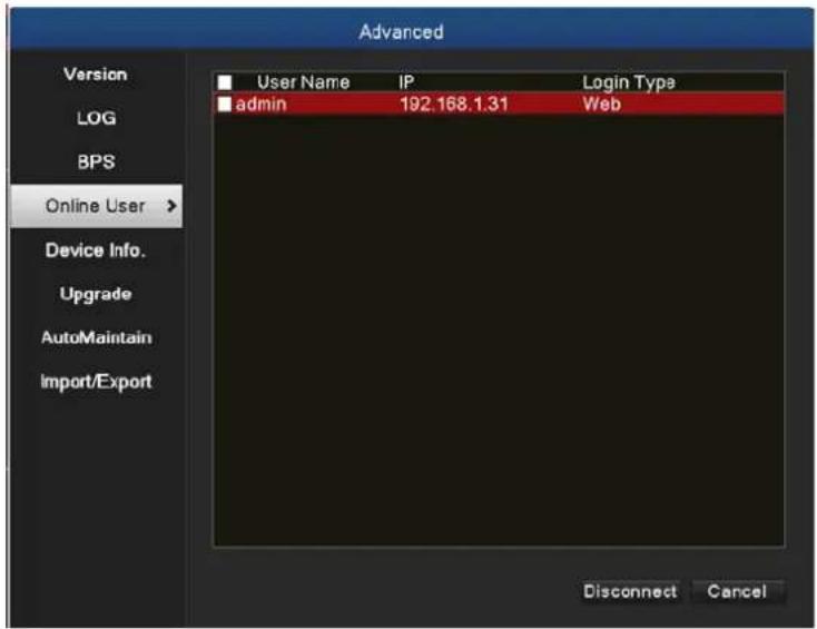
Picture 5.31 Online User
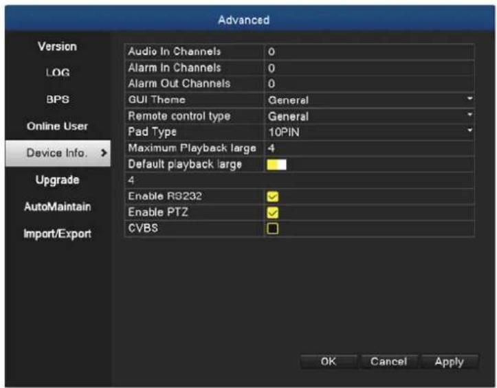
5.7.5 Device Info
Provide information of device interface like audio in, alarm in/out.
Picture 5.32 Device Information
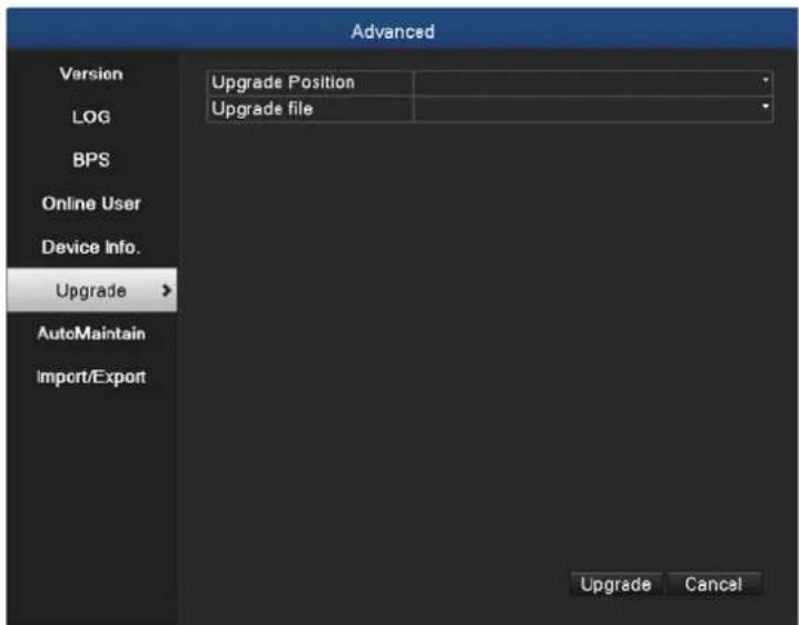
5.7.6 Upgrade
Picture 5.33 Upgrade
Upgrade: Choose USB interface.
Upgrade file: Choose the upgrade file.
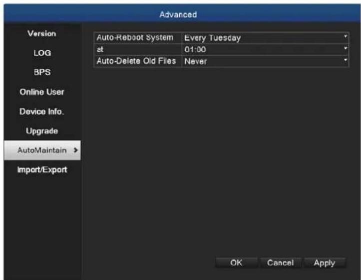
5.7.7 Auto Maintain
The user can set the time to auto reboot and auto delete file.
Picture 5.34 Auto Maintain
5.7.8 Import/Export
Users can export the log info and the configure file from device to connected flash stick, and also can import related configure file from flash stick to settings, which greatly bring
convenience to the customers.
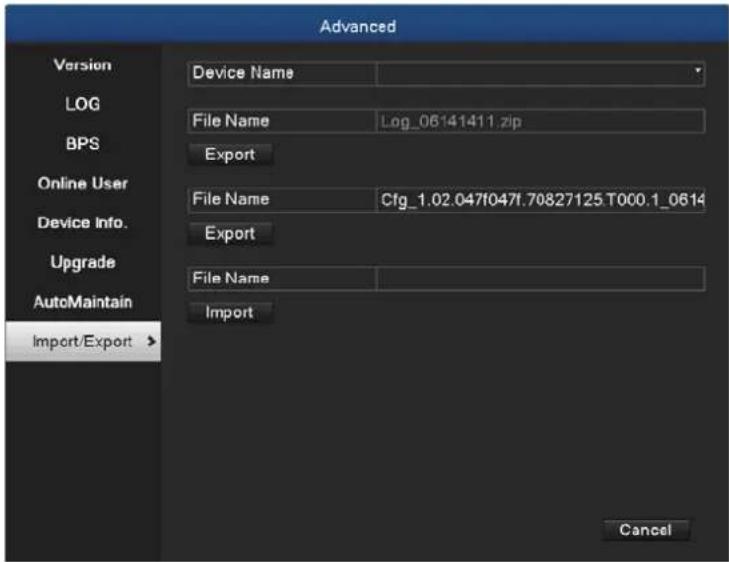
Picture 5.35 Import/Export Interface
5.8 HDD Management
Configure and manage the hard disk. The menu displays the following current hard disk information: hard disk number, input port, type, status and overall capability. The operation setup includes the write-read disk, read-only disk, redundant disk, hard disk format, recover and partition. Choose the hard disk and right-click to execute.

Read/Write Disk: The equipment can write or read data.
Read-only Disk: The equipment can read data but cannot write data.
Redundant Disk: Double-back up the video files in the write-read disk.
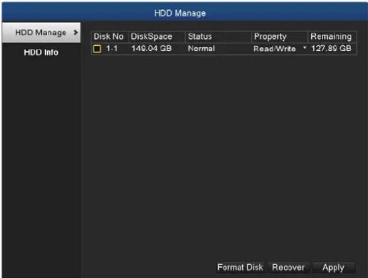
Picture 5.36 HDD Manage
5.8.1 HDD Info
Display the hard disk state and it lists hard disk type, overall capability, residual capability, the recording time, etc.
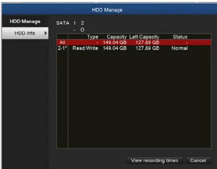
Picture 5.37 HDD Info
Tips: Symbol “○” means that the hard disk is normal; symbol “X” means that the hard disk is broken down; symbol “-” means that there is no hard disk. If you need to replace the damaged hard disk, you must shut down the HDVR, take out all the damaged hard disks and then install new ones.
Symbol “*” behind serial number means the current working disk such as 1*. If the corresponding disk is damaged, the information will show “?”.
5.9 Network
Manage tools menu provides Network, DDNS, UPNP, Email, Cloud and Net Service.
5.9.1 Network Setup
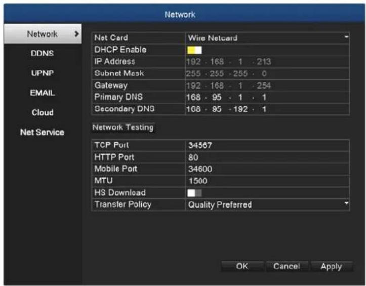
Picture 5.38 Network Setup
| Net Card | You can choose cable network card or wireless network card. |
| DHCP Enable | Obtain IP address automatically. |
| IP Address | Set the IP address. Default: 192.168.0.20. |
| Subnet Mask | Set the subnet mask code. |
| Gateway | Set the default gateway. |
| DNS Setup | Domain Name Server. It translates the domain name into IP address. The IP address is offered by network provider. The |
address must be set and reboot to enable to work.
Media Port Default: 34567.
HTTP Port Default: 80.
HS Download Network high-speed download
There are three strategies: self-adaption, image quality precedence and fluency precedence. The code stream will adjust according to the setup. Self-adaption is the tradeoff
Transfer Policy between the image quality precedence and fluency precedence. Fluency precedence and self-adaption are valid only when the assistant code stream is turned on. Otherwise, image quality precedence is valid.
5.9.2 DDNS
Picture 5.39 DDNS Setup
It is the abbreviation of dynamic domain name server.
DDNS Type DDNS service providers; PLANET DDNS is free to register.
| Domain Name | Provide the domain name registered by DDNS. For example, hdvr1630test.planetddns.com |
| User Name | Provide the account registered by DDNS. |
| Password | Provide the password registered by DDNS. When the DDNS is successfully configured and starts, you can connect the domain name in the IE address column to visit. |

Note
- The DNS setup must be configured correctly in the network setup.
- It is not necessary to input user name and password for Easy DDNS. The system will generate a domain name automatically according to MAC address.
5.9.3 UPNP
UPNP protocol is to realize auto port forwarding on router, precondition of using this function is to make sure the UPNP function of router is enabled.
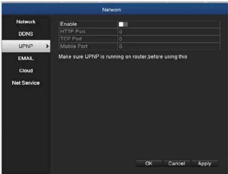
Picture 5.40 UPnP Setup
| Enable | It means the function is activated when the box is checked. |
| HTTP Port | Router will automatically distribute HTTP port for the device.The port is needed when live view is made via Web. |
| TCP Port | Router will automatically distribute TCP port for the device. The port is needed when live view is made via CMS. |
5.9.4 EMAIL
If the alarm is turned on or the alarm linkage photos are taken, send an email about the alarm information and the photos to appointed address.
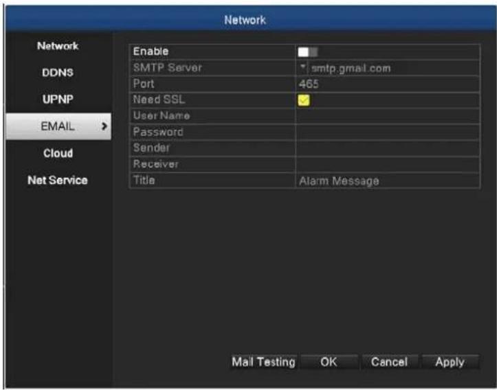
Picture 5.41 Email Setup
| SMTP Server | Email server address. It could be an IP address or domain name. Domain name can be translated only it is the correct DNS configuration. |
| Port | Email server port number. |
| SSL | Decide whether using Secure Socket Layer protocol to login. |
| User Name | Apply the email server user name. |
| Password | Input the password corresponding to the user. |
| Sender | Set the email sender address. |
| Receiver | Send the email to appointed receivers when the alarm is turned on. You can set three receivers at most. |
Title
You can set a message as you want (e.g. Alarm Message).
5.9.5 Cloud
The cloud function is enabled by default. The user is able to scan the iOS or Android QR code to install app viewer (OKview) on mobile. The app viewer can help user to monitor channels of the HDVR remotely.
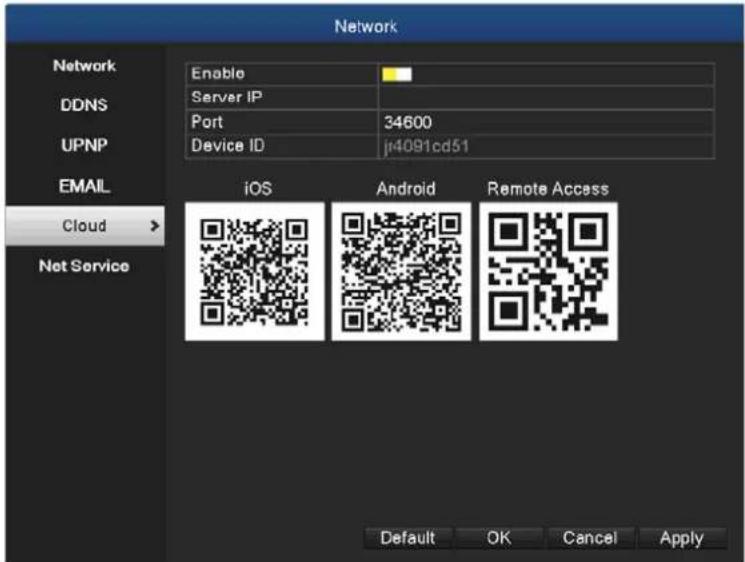
Picture 5.42 Cloud
When you execute OKview app, you can input the required information as below then press the "save" button to take effect.
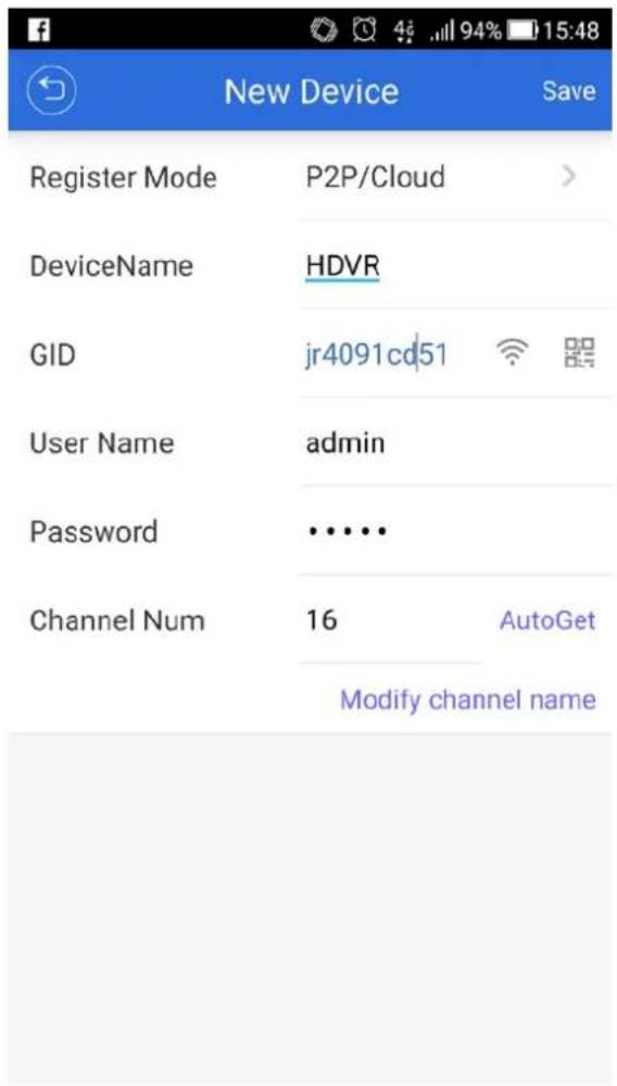
Picture 5.43 App Setup

In GID field, you can double click the QR code icon to start your QR code scanner app. Next, please scan the Remote Access QR code or the Remote Access QR code label on the button of the case to input the device ID.
5.9.6 Net Service
The Net Service provides PPPoE, RTSP, IP Filter, FTP, NTP and Dropbox functions.
Choose the network service option and click the set button to configure the advanced network functions or double-click the service button to configure the parameters.
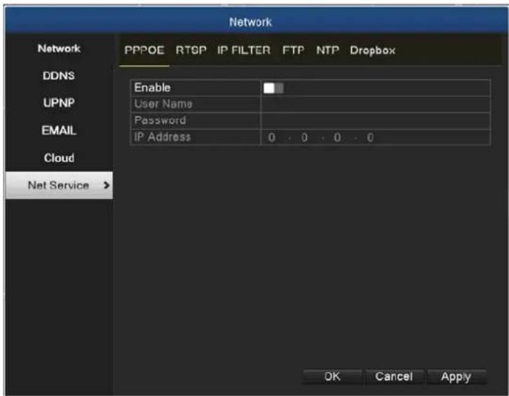
Picture 5.44 Net Service Setup
PPPoE Setup
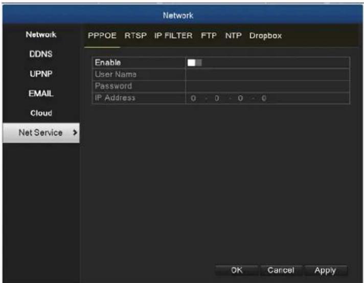
Picture 5.45 PPPoE Setup
Input the user name and password that ISP (Internet service provider) provides. After saving it, reboot your system. Then the HDVR will build a network connection based on PPPoE. The IP address will change to dynamic IP address after the above operation is well done.
Operation: The current IP address is displayed after successful dial-up. Use this IP address to
visit the HDVR through user port.
RTSP Setup
The setting is for live view via browsers (Safari, Firefox, and Chrome) and VLC software. This function is only for live view and it cannot control the device.
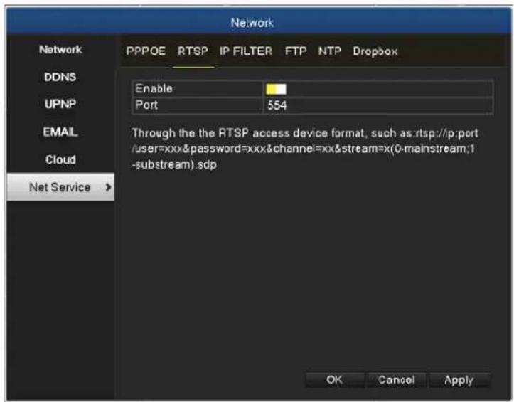
Picture 5.46 RTSP Setup
| Enable | It means the function is activated when the box is checked. |
| Port | The default port number is 554. |
IP Filter Setup
When choosing the white list, only the listed IP address can connect the HDVR. The 64 IP addresses are supportive in the list. When choosing the black list, the listed IP address cannot connect the HDVR. The 64 IP addresses are supportive in the list.
You can delete the set IP address by √ in the options.

When the same IP address is in the white and black list at the same time, the black list precedence is higher.
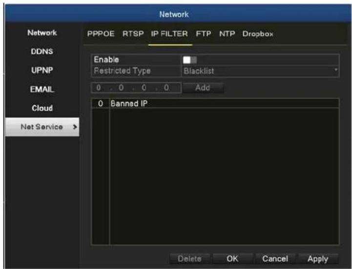
Picture 5.47 IP Filter Setup
FTP Setup
FTP is available only when alarm happens or alarm activates record and snapshot. It will upload related record and snapshot pictures to FTP server.
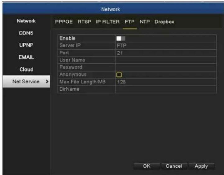
Picture 5.48 FTP Setup
| Server IP | IP address of FTP server |
| Port | Port number of FTP server. The default value is 21 |
| User Name | User name of FTP server |
| Password | Password of FTP server |
| Anonymous | When anonymous is enabled, setting user name and password is not required |
| Max. File Length | Max. length for uploaded files at every packed, default value is 1024M |
| Dir Name | The directory of uploaded files |

The user should have authority to upload files.
NTP Setup
The NTP server must be installed in the PC.
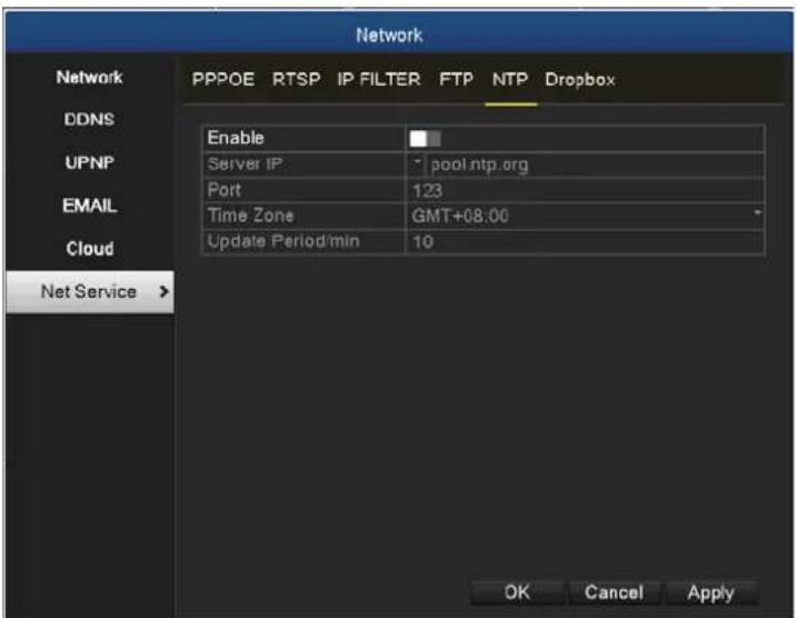
Picture 5.49 NTP Setup
| Server IP | Input the IP address installed on NTP server. |
| Port | Default: 123. You can set the port according to NTP server. |
| Update Period | The same with the NTP server check interval. Default: 10 minutes. |
Dropbox Setup
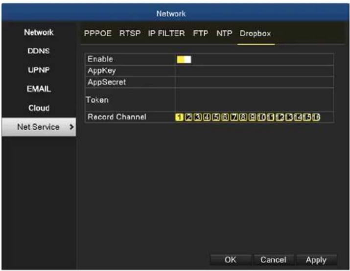
Picture 5.50 Dropbox
The procedure follows below:
- Log in with a Dropbox account to apply for a Drobox space. Go to
https://www.dropbox.com/developers/apps and create an app (click on the "Create app" button). The interface is shown below.
Create a new app on the DBX Platform
- Choose an API
Dropbox API
For apps that need to access files in Dropbox. Learn more

Dropbox Business API
For apps that need access to Dropbox Business team info. Learn more

- Choose the type of access you need
Learn more about access types
App folder – Access to a single folder created specifically for your app.
Full Dropbox - Access to all files and folders in a user's Dropbox.
- Name your app
SimonTestApp3
Here we create a normal API, the permissions for the directory and the name is SimonTestApp3. Specify the "Create app" button, then enter the following interface:
SimonTestApp3
Settings
Branding
Analytics
Status
Development
Development users
Only you
Permission type
App folder
App folder name
SimonTestApp3
Apply for production
Enable additional users
Change
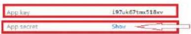
Firstly, click the "Enable additional users" button. Next, click the "OKay" button in the pop-up dialog box, and then click "Show" after the APP secret to display the contents of the secret. As shown below:
Limit raised to 500 users
Your app can now be linked with up to 500 users. If you'd like to link more than 500 users, please apply for production status. Learn more about production status requirements.
Okay
SimonTestApp3
| Settings | Branding | Analytics |
| Status | Development | |
| Development users | 0 / 500 | |
| Permission type | App folder. | |
| App folder name | SimonTestApp3 | |
| App key | i97uk67bxx518xv | |
| App secret | hx302bx2ynyrfdx | |
Set the corresponding parameters, click the "Apply for production" button, and mainly remember the contents of the App key and App secret. We need to use it for the device configuration. If you don't remember it, you can view all the created apps at https://www.dropbox.com/developers/apps. You can also view them by clicking on the corresponding app.
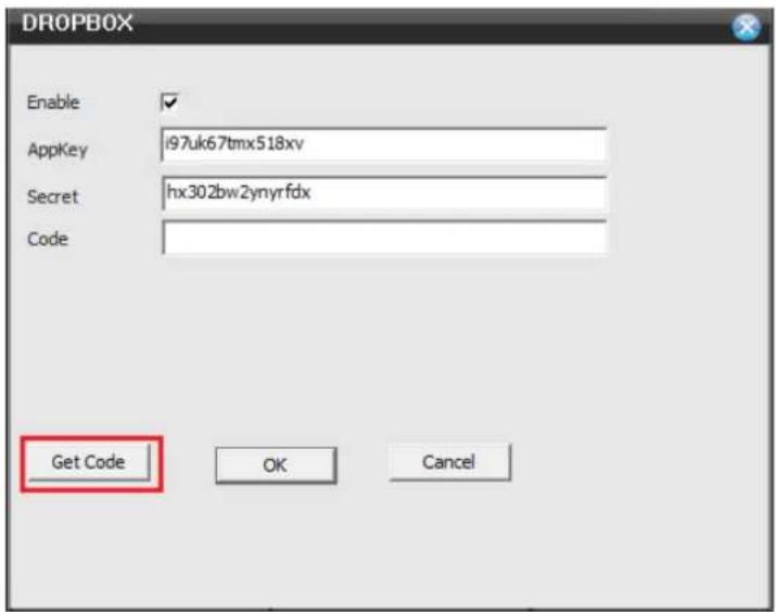
- Log in the device with IE, go to the "Net Service→Dropbox" configuration interface, then check Enable, and copy the values of App Key and App Secret in Step 1 to the "Key" and "Secret" columns in the configuration interface. After clicking the "Get Code" button and a new web page will be opened.
- In the newly opened page, follow the prompts and finally copy the Code value in the following figure to the "Code" column in the "Network Service Dropbox" configuration interface.
Note: Be sure to complete the operation within 3 minutes, otherwise the code will expire.
![Dropbox, Inc [US] | https://www.dropbox.com/1/auth2/authorize_submit 在「SimonTestApp3」中输入此操作已完成程序。 Rkj0ucb94kAABAAAAAH-f2juHfxzRelsCOnalN7jYQ](/content/2026/05/1044032/images/8373acc123b3db27ca50de208ebd0dd844974f760c0a20e01e65dcb34d5ca32e.jpg)
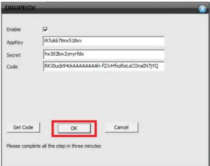
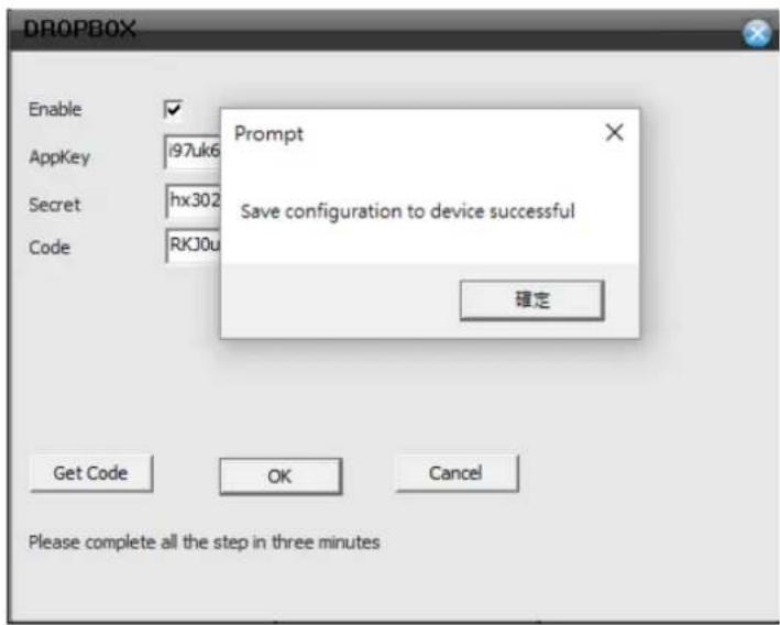
- Click "OK" and wait for the result. If the configuration fails, repeat steps 2 and 3 until the configuration is successful.
5.10 Camera
The camera function includes camera manage, channel status and channel type.

There is only analog mode if device is in full analog mode
Channel Manage Page in All Analog (DVR) Mode
Picture 5.51 Camera Interface

Channel Manage Page in Hybrid Mode/Full Digital Mode
Picture 5.52 Camera Interface
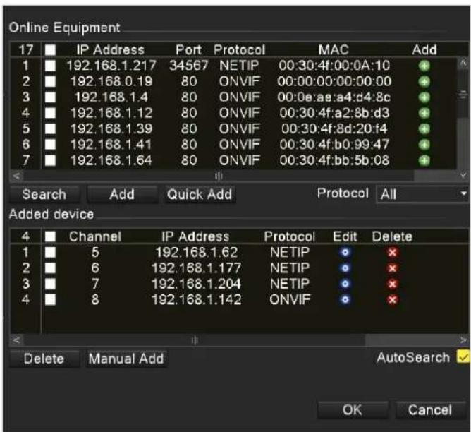
Digital Channel:
Picture 5.53 Single Link Page of Digital Channel
| Channel | Select channel title |
| Enable | When the digital channel is enabled, user is able to configure related settings for the channel. |
| Time Synchronization | When the function is enabled, the time of channel will be the same as the device. |
| Connection Mode | Can be singly connected or in multi-link mode. In multi-link mode, it can connect to several devices, and the device will be displayed one by one. Tour interval can be set no less than 10s. |
| Delete | If you want to remove the device, you can select specific device and click the delete button. |
| Add | Click the add button to add new device. |
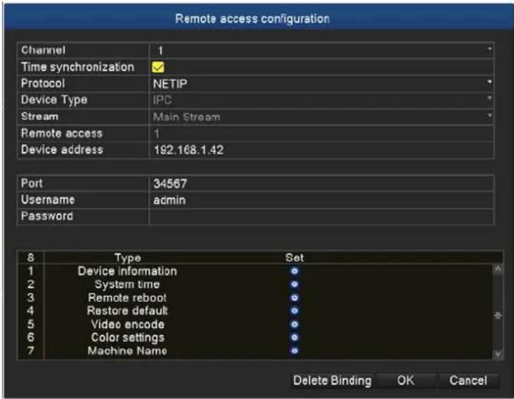
Picture 5.54 Remote Channel Configuration
| Configure Name | Default configuration title of the device. User can modify it if necessary. |
| Device Type | Default is IPC |
| Protocol | Default is NETIP |
| Remote Channel | User can input remote channel title from the device that you want to connect remotely |
| Stream | Default is main stream |
| Device Address | IP address of device. |
| Port | Default is 34567 |
| User Name | Default is admin |
After clicking the Search button, the list will show all the devices in the network. User can choose any device that you prefer.
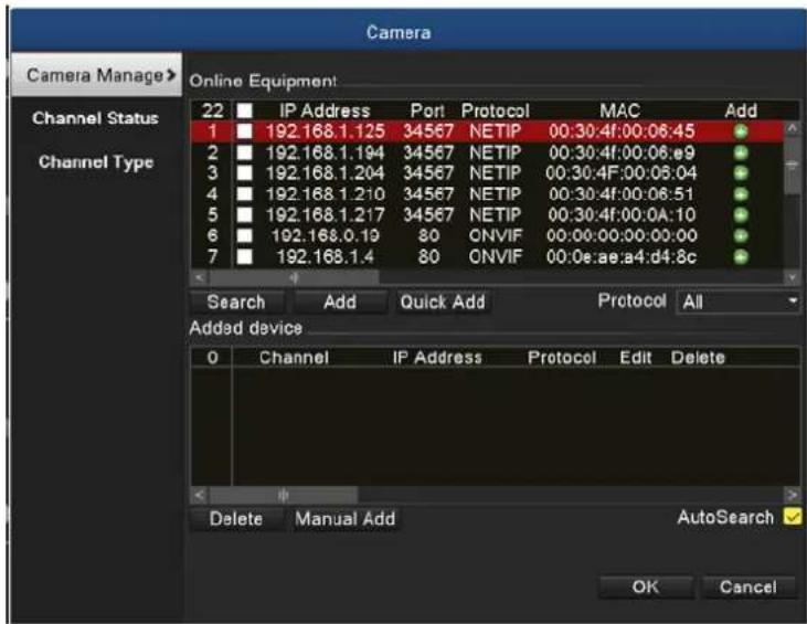
Picture 5.55 Device Searched List
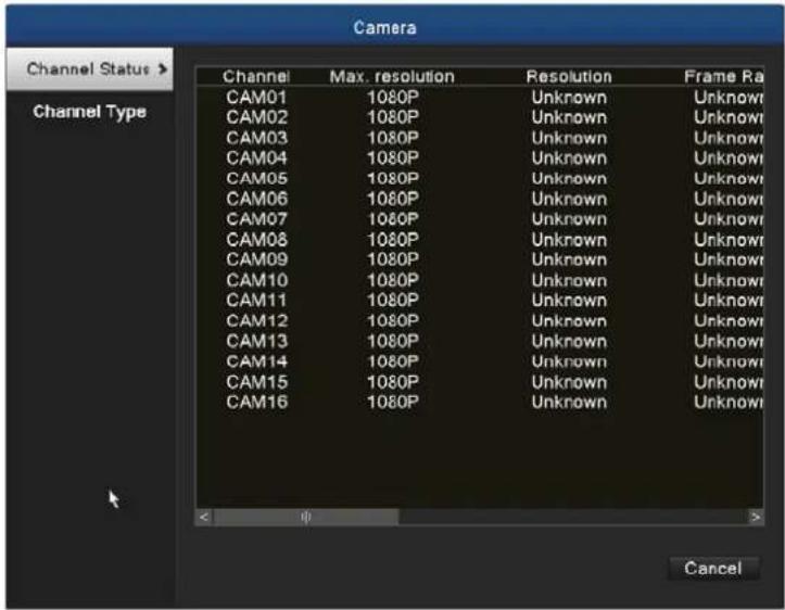
Channel Status:
Channel status is to show the status of all digital channels which are connected. The status information includes channel, maximum resolution, frame rate and connection status.
For example, the channel status for 8+8 mode (16-ch Hybrid mode) is shown below.
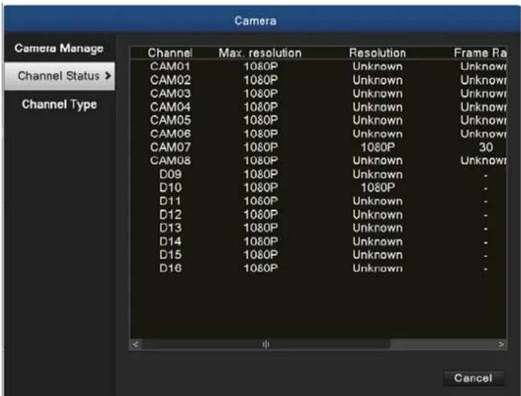
Picture 5.56 Channel Status
When a channel is added to device but it is not enabled, you will see as shown below.
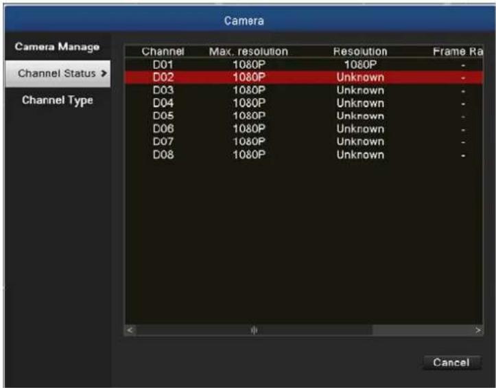
Picture 5.57 Resolution Status
Channel status interface is in full digital mode; the first channel with 5MP resolution is disconnected because of resolution limitation (1080p).
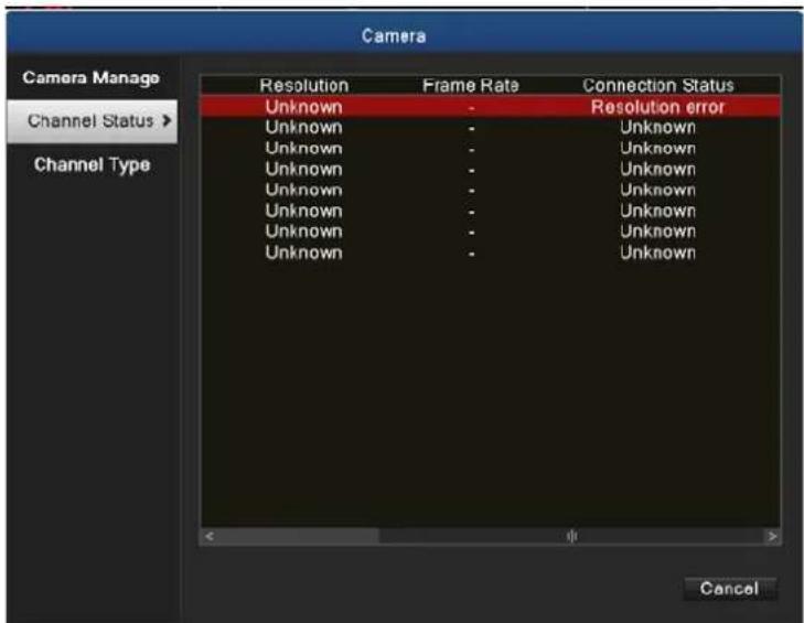
Picture 5.58 Connection Status

Note
When the current resolution is over the max resolution that the channel supports, then a red "Out of Resolution" will be shown on the preview image.
Channel Type:
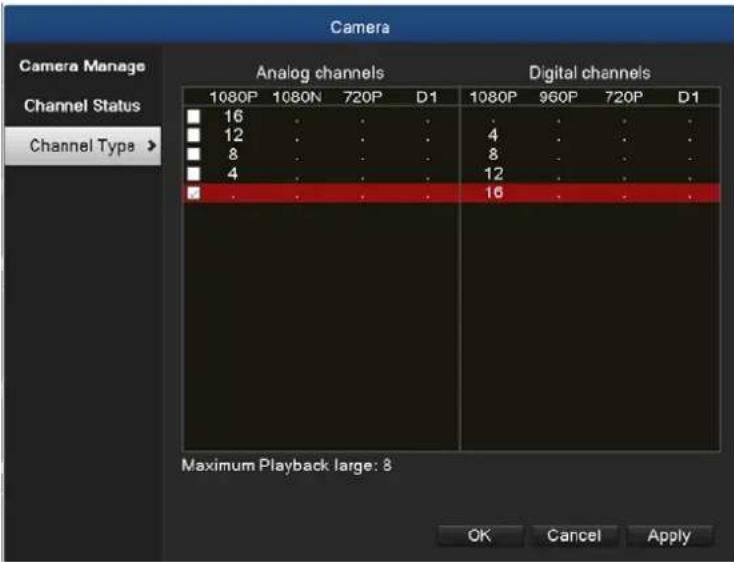
Picture 5.59 Channel Type

In this series of product, the HDVR provides full analog channel mode, hybrid mode and full digital mode in channel type. Different models have different channel modes. User can shift the mode freely if necessary.
5.11 Logout
In logout setup interface, it comes with logout, shutdown and reboot functions. You can use the desktop shortcut menu or enter [main menu].
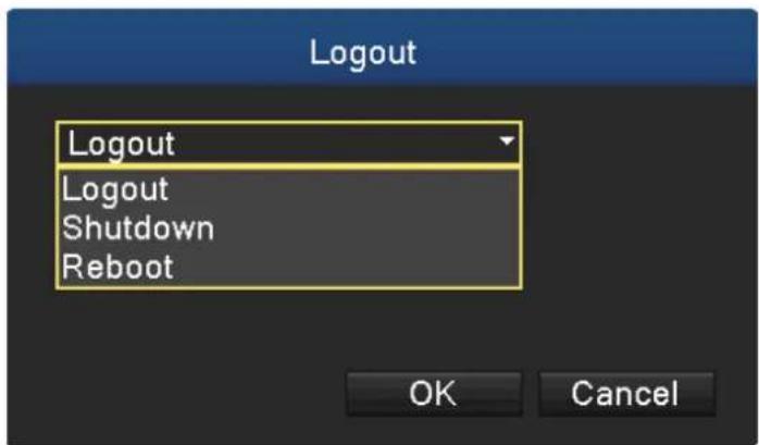
Picture 5.60 Logout, Shutdown, Reboot
| Logout | Press to log out; password is needed to re-enter. |
| Shutdown | Press to turn off the system after three seconds. Cancel midway is of no effect. |
| Reboot | Press to reboot the system. |
Chapter 6. Web Remote Management
The HDVR is able to be viewed from Internet Explorer when the network is available. You can have live view, playback and most of the functions that are the same as those of the HDVR system.
6.1 Connecting to HDVR
For first-time connection, you need to install the ActiveX control if it appears on your web page shown below:

This website wants to install the following add-on: 'web.cab' from 'PLANET Technology Corporation'.
![User Account Control Do you want to allow the following program to make changes to this computer? Program name: [1]web[1].cab Verified publisher: PLANET Technology Corporation File origin: Downloaded from the Internet Show details Yes No Change when these notifications appear](/content/2026/05/1044032/images/b7c65cab2e8b745d11a2a771759801cd605342616d82b30c2430e7956cfe28f6.jpg)
After the ActiveX component is installed, login the system on pop-up window.
Please login your username and password. When you click "connect all video" button, you will
see the "Bit Rate Type" window shown below:
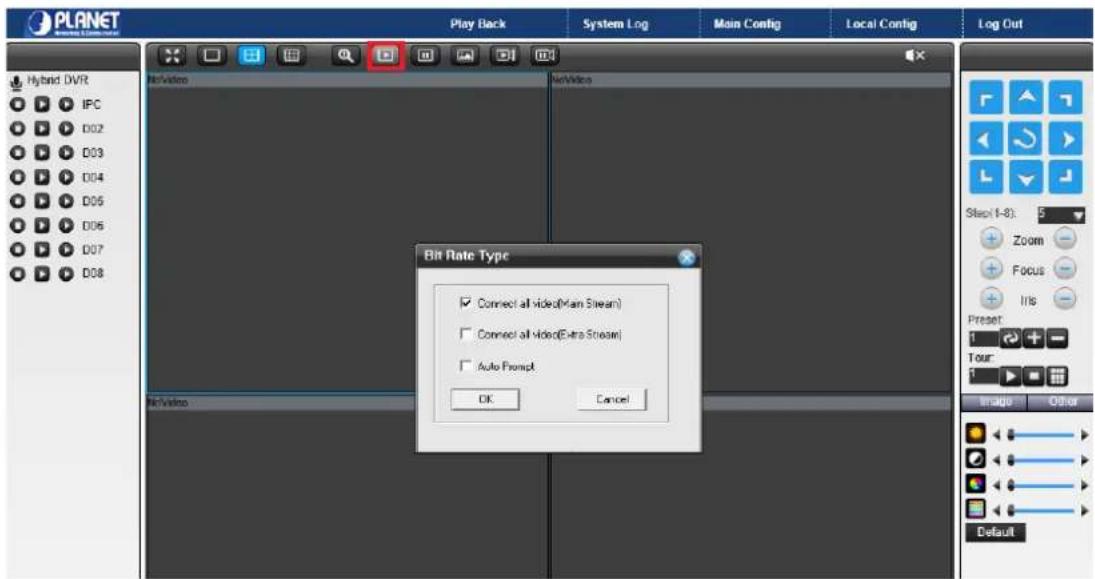
You may select bit rate type you would like to view on your computer. The bit rate type can impact bandwidth consumption on IE.
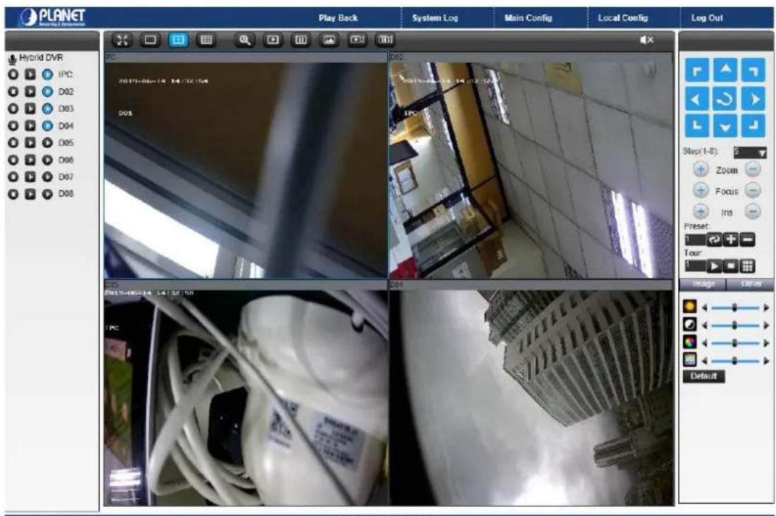
6.2 Live View on Browser
On the main page, the Web user interface provides playback, log, main config, local config and logout functions. All the main settings of the device are on the main config page.
Appendix A: Ping IP Address
The ping (Packet Internet Groper) command is used to detect whether a specific IP address is accessible by sending a packet to the specific address and waiting for a reply. It's also a very useful tool to confirm whether or not Internet camera is installed or if the IP address conflicts with any other device over the network.
If you want to make sure the IP address of Internet camera, utilize the ping command as follows:
- Start a DOS window.
• Type ping x.x.x.x, where x.x.x.x is the IP address of the Internet camera.
The replies, as illustrated below, will provide an explanation to the problem.
![Microsoft Windows XP [Version 5.1.2600] (C) Copyright 1985-2001 Microsoft Corp. D:\Documents and Settings\Administrator>PING 192.168.0.20 Pinging 192.168.0.20with 32 bytes of data: Reply from 192.168.0.20: bytes=32 time=1ms TTL=64 Reply from 192.168.0.20: bytes=32 time<1ms TTL=64 Reply from 192.168.0.20: bytes=32 time<1ms TTL=64 Reply from 192.168.0.20: bytes=32 time<1ms TTL=64 Ping statistics for 192.168.0.20: Packets: Sent = 4, Received = 4, Lost = 0 (0% loss), Approximate round trip times in milli-seconds: Minimum = 0ms, Maximum = 1ms, Average = 0ms D:\Documents and Settings\Administrator>](/content/2026/05/1044032/images/8f97bab62f6396d92359a3a5e41105e499d7a210bc5e3b58d768a75c1f57329f.jpg)
If you want to detect any other device that conflicts with the IP address of Internet camera, you also can utilize the ping command but you must disconnect the Internet camera from the network first.
Appendix B: Planet DDNS Application
Configuring PLANET DDNS Steps:
Step 1 Visit DDNS provider's web site and register an account if you do not have one yet. For example, register an account at http://planetddns.com
Step 2 Enable DDNS option through accessing web page of the camera.
Step 3 Input all DDNS settings.

Appendix C: Configuring Port Forwarding Manually
The device can be used with a router. If the device wants to be accessed from the WAN, its IP address needs to be set up as a fixed IP address. The port forwarding or Virtual Server function of router also needs to be set up. This device supports UPnP traversal function. Therefore, user could use this feature to configure port forwarding of NAT router first. However, if user needs to configure port forwarding manually, please follow the steps below:
Manually installing the device with a router on your network is an easy 3-step procedure as follows:
- Assign a local/fixed IP address to your device
- Access the router with your web browser
- Open/Configure virtual server ports of your router
1. Assigning a local/fixed IP address to your device
The device must be assigned a local and fixed IP address that allows it to be recognized by the router. Manually set up the device with a fixed IP address, for example, 192.168.0.100.
2. Accessing the Router with Your Web browser
The following steps generally apply to any router that you have on your network. PLANET WNRT-620 is used as an example to clarify the configuration process. Configure the initial settings of the router by following the steps outlined in the router's Quick Installation Guide. If you have cable or DSL service, you will most likely have a dynamically assigned WAN IP address. 'Dynamic' means that your router's WAN IP address can change from time to time depending on your ISP. A dynamic WAN IP address identifies your router on the public network and allows it to access the Internet. To find out what your router's WAN IP address is, go to the Status screen on your router and locate the WAN information for your router.
As shown on the following page the WAN IP address will be listed. This will be the address that you will need to type in your web browser to view your camera over the Internet. Be sure to uncheck the Reset IP address at the next boot button at the top of the screen after modifying the IP address. Failure to do so will reset the IP address when you restart your computer.
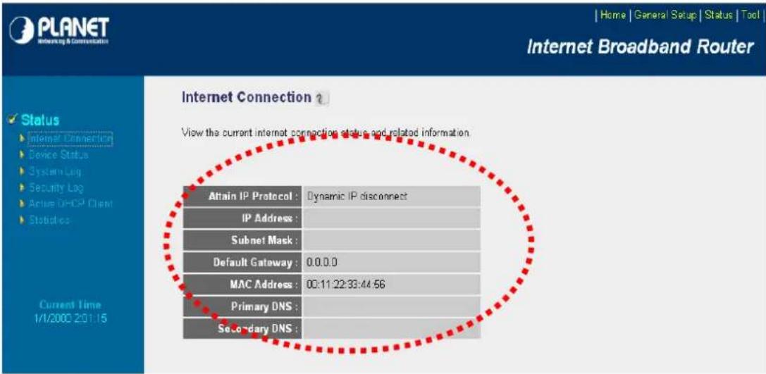
Your WAN IP address will be listed here.
3. Opening/Setting Virtual Server Ports to enable remote image viewing
The firewall security feature is built into the router and most routers prevent users from accessing the video from the device over the Internet. The router connects to the Internet over a series of numbered ports. The ports normally used by the device are blocked from access over the Internet. Therefore, these ports need to be made accessible over the Internet. This is accomplished using the Virtual Server function on the router. The Virtual Server ports used by the camera must be opened through the router for remote access to your camera.
Follow these steps to configure your router's Virtual Server settings
- Click Enabled.
- Enter a unique name for each entry.
- Select Both under Protocol Type (TCP and UDP)
- Enter your camera's local IP address (192.168.0.100, for example) in the Private IP field.
- If you are using the default camera port settings, enter 80 into the Public and the Private Port section and click Add.
A check mark appearing before the entry name will indicate that the ports are enabled.

Some ISPs block access to port 80. Be sure to check with your ISP so that you can open the appropriate ports accordingly. If your ISP does not pass traffic on port 80, you will need to change the port the camera uses from 80 to something else, such as 8080. Not all routers are the same, so refer to your user manual for specific
instructions on how to open ports.
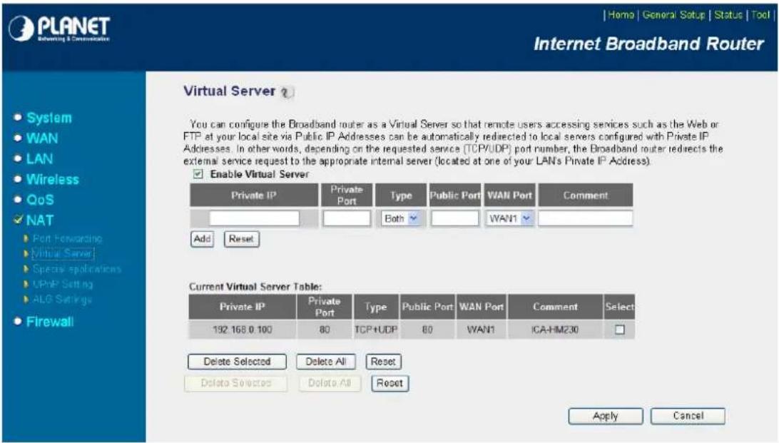
Enter valid ports in the Virtual Server section of your router. Please make sure to check the box on this line to enable settings. Then the device can be accessed from WAN by the router's WAN IP address.
By now, you have finished your entire PC configuration for this device.