NVR-1600 - Video recorder Planet - Free user manual and instructions
Find the device manual for free NVR-1600 Planet in PDF.


| Product Type | Network Video Recorder (NVR) |
| Brand | Planet |
| Model | NVR-1600 |
| Dimensions (W x D x H) | 300 x 200 x 50 mm |
| Weight | 2 kg |
| Power Supply | 12V DC, 2A (adapter included) |
| Power Consumption | ≤15W |
| Video Inputs | 16 x IP camera channels (PoE) |
| Video Compression | H.265+/H.265/H.264+/H.264 |
| Recording Resolution | Up to 8MP per channel |
| Storage | 2 x SATA HDD bays (up to 10TB each) |
| Network Interface | 1 x RJ45 10/100/1000 Mbps |
| Remote Access | Via web browser, mobile app (iOS/Android) |
| Operating Temperature | 0°C to 40°C |
| Main Functions | Live view, playback, motion detection, email alerts, backup via USB |
| Maintenance | Clean with dry cloth; ensure ventilation; keep firmware updated |
| Safety | Use only supplied power adapter; avoid liquid exposure; do not open case |
| Spare Parts & Repairability | Hard drives and power adapter replaceable; contact support for other parts |
| General Information | Suitable for small to medium surveillance systems; supports ONVIF cameras |
Frequently Asked Questions - NVR-1600 Planet
User questions about NVR-1600 Planet
0 question about this device. Answer the ones you know or ask your own.
Ask a new question about this device
Download the instructions for your Video recorder in PDF format for free! Find your manual NVR-1600 - Planet and take your electronic device back in hand. On this page are published all the documents necessary for the use of your device. NVR-1600 by Planet.
USER MANUAL NVR-1600 Planet
natural_image
Black industrial server unit with ventilation grilles and ports (no visible text or symbols)H.265+ 16-ch 4K Network Video Recorder

NVR-1600

natural_image
Group of business professionals in a meeting around a laptop, no visible text or symbolsCopyright
Copyright © 2023 by PLANET Technology Corp. All rights reserved. No part of this publication may be reproduced, transmitted, transcribed, stored in a retrieval system, or translated into any language or computer language, in any form or by any means, electronic, mechanical, magnetic, optical, chemical, manual or otherwise, without the prior written permission of PLANET.
PLANET makes no representations or warranties, either expressed or implied, with respect to the contents hereof and specifically disclaims any warranties, merchantability or fitness for any particular purpose. Any software described in this manual is sold or licensed "as is". Should the programs prove defective following their purchase, the buyer (and not PLANET, its distributor, or its dealer) assumes the entire cost of all necessary servicing, repair, and any incidental or consequential damages resulting from any defect in the software. Further, PLANET reserves the right to revise this publication and to make changes from time to time in the contents hereof without obligation to notify any person of such revision or changes.
All brand and product names mentioned in this manual are trademarks and/or registered trademarks of their respective holders.
Federal Communication Commission Interference Statement
This equipment has been tested and found to comply with the limits for a Class B digital device, pursuant to Part 15 of FCC Rules. These limits are designed to provide reasonable protection against harmful interference in a residential installation. This equipment generates, uses, and can radiate radio frequency energy and, if not installed and used in accordance with the instructions, may cause harmful interference to
radio communications. However, there is no guarantee that interference will not occur in a particular installation. If this equipment does cause harmful interference to radio or television reception, which can be determined by turning the equipment off and on, the user is encouraged to try to correct the interference by one or more of the following measures:
- Reorient or relocate the receiving antenna.
- Increase the separation between the equipment and receiver.
- Connect the equipment into an outlet on a circuit different from that to which the receiver is connected.
- Consult the dealer or an experienced radio technician for help.
FCC Caution
To assure continued compliance, use only shielded interface cables when connecting to computer or peripheral devices. Any changes or modifications not expressly approved by the party responsible for compliance could void the user's authority to operate the equipment. This device complies with Part 15 of the FCC Rules. Operation is subject to the following two conditions: (1) This device may not cause harmful interference, and (2) this device must accept any interference received, including interference that may cause undesired operation.
Federal Communication Commission (FCC) Radiation Exposure
Statement
This equipment complies with FCC radiation exposure set forth for an uncontrolled environment. In order to avoid the possibility of exceeding the FCC radio frequency exposure limits, human proximity to the antenna shall not be less than 20 ~cm (8 inches) during normal operation.
Safety
This equipment is designed with the utmost care for the safety of those who install and use it. However, special attention must be paid to the dangers of electric shock and static electricity when working with electrical equipment. All guidelines of this and of the computer manufacture must therefore be allowed at all times to ensure the safe use of the equipment.
CE Mark Warning
This is a Class B product. In a domestic environment, this product may cause radio interference, in which case the user may be required to take adequate measures.
WEEE Regulation

To avoid the potential effects on the environment and human health as a result of the presence of hazardous substances in electrical and electronic equipment, end users of electrical and electronic equipment should understand the meaning of the
crossed-out wheeled bin symbol. Do not dispose of WEEE as unsorted municipal waste and have to collect such WEEE separately.
Energy Saving Note of the Device
This power required device does not support Standby mode operation. For energy saving, please remove the AC-plug to disconnect the device from the power circuit.
Without remove the AC-plug or switch off the device, the devices will still be consuming power from the power circuit. In the view of Saving the Energy and reduce the unnecessary power consuming, it is strongly suggested to switch off or remove the DC-plug for the device if this device is not intended to be active.
Revision
User's Manual of PLANET H.265+ 16-ch 4K Network Video Recorder
Model: NVR-1600
Rev: 1.0 (June, 2023)
Part No. EM-NVR-1600_v1.0
Declaration
Copyright ©2023. All rights reserved.
Without the written permission of the company, any company or individual should not extract, duplicate part of or all of contents of this manual and no spreading in any form.
As the upgrade of the products or other reason, the contents of manual will be upgraded periodically. Unless otherwise stipulated, the manual is used as a NOTE. All statements, information and suggestions of the manual do not constitute any ostensive or implied guarantee.
Photographs, graphics, charts, and illustrations provided in the manual are for explanation and illustration purposes only, and may differ from specific products. Please prevail in kind.
Safety Precautions

CAUTION
- Please do not place and install equipment directly under the sunlight or near heating device.
- Please do not install equipment at moist place or place with dust or soot.
- Please keep equipment installed horizontally, or install equipment in a stable place, avoid the equipment falling down.
- Please avoid liquid dropping on the equipment, make sure no objects filled (eg cups) with liquid on the equipment and prevent liquid from leaking.
- Please install the device in a well-ventilated place, do not block the vents of the equipment.
- Please only use equipment within rated input/output.
-
Please do not disassemble at liberty.
-
Please transport, use and reserve the equipment within allowing humidity (10%\~90%) and temperature (-10°C\~+55°C).
- When cleaning the device, unplug the power cord and completely shut off the power.
- The dust on the circuit board inside the NVR may cause a short circuit after being exposed to moisture. Regularly clean the circuit board, connectors, chassis, and chassis fan with a soft brush. If dirt is difficult to remove, wipe it off with a neutral detergent diluted in water and wipe it dry.
- Do not use volatile solvents such as alcohol, benzene, or thinner when cleaning the device. Do not use strong or abrasive cleaning agents. This can damage the surface coating.
- Please purchase the NVR dedicated hard drive recommended by the equipment manufacturer from the formal channels to ensure the quality and usage requirements of the hard drive.
● Make sure that there is no threat due to uneven mechanical load.
● Make sure that the video and audio cables have enough controls to install the cable. The bend radius of the cable should not be less than 5 times the cable diameter.
● Make sure that the alarm cable is firmly installed and the contact is good.
● Make sure that the NVR is reliably grounded.

WARNING
- Please do use the battery as requested, or it may lead to a battery fire, explosion or risk of burning!
- Please use the same type of battery when changing it.
- Please do use recommended cord sets (power cords), do use within the rated specifications.
- If you connect the product to the Internet at your own risk, including but not limited to products that may be subject to cyber-attacks, hacking attacks, virus infections, etc., the company will not be responsible for product abnormality, information leakage, etc., but the company will timely to provide you with product-related technical support.

Note
- After receiving the product, please open the packing box, take out the equipment, and confirm the packing product and accessories according to the packing list in the box.
- If you find any damage to the contents of the box or any missing parts, please contact your dealer promptly.
Contents
Chapter 1 Outlines and Features....13
1.1 Outlines....13
1.2 Default....14
1.3 Descriptive content agreement....15
1.4 Function Features .... 16
Chapter 2 NVR Appearance ....20
2.1 Front Panel ....20
2.2 Rear Panel 21
2.3 Mouse Description ...... 22
2.4 Input Method Introduction 23
Chapter 3 Connecting NVR ......24
3.1 Hard Disk Installation 24
3.2 Device Connection....25
Chapter 4 NVR Startup....26
4.1 System Initialization 26
4.2 Boot wizard .....28
4.2.1 Quick Startup Wizard....28
4.2.2 Forget Password....33
4.3 Preview Interface 37
4.4 Quick add device ....38
Chapter 5 NVR Menu....40
5.1 Shortcut menu....40
5.2 Main Menu 42
5.3 Preview 44
5.3.1 Channel shortcut menu 45
5.3.2 PTZ 46
5.3.3 Image Configuration 48
5.4 Playback ....50
5.4.1 Playback channel video....50
5.4.2 Playback assistance function ..... 54
5.5 Search....59
5.5.1 Video....59
5.5.2 Smart 61
5.5.3 Picture....63
5.5.4 Log....65
5.6 Config....66
5.6.1 Easy Mode....66
5.6.1.1 System Config 66
5.6.1.2 Network Config....77
5.6.1.3 Channel Manage 84
5.6.1.4 Record Manage....95
5.6.2 Expert Mode ....106
5.6.2.1 System Config 106
5.6.2.2 Network Config.... 115
5.6.2.3 Channel Manage 136
5.6.2.4 Event Config 148
5.6.2.5 Record Manage....165
5.7 Maintain 179
5.7.1 System Message 179
5.7.2 Device Upgrade....180
5.7.3 Restore Default....184
5.7.4 Automatic Maintenance ....185
5.7.5 Import And Export....186
5.7.6 Channel Information 187
Chapter 6 WEB Operation ....188
6.1 Internet connection .... 188
6.2 Browser Login 190
6.3 Active X download, installation ....192
6.4 Live View....195
6.5 Playback 198
6.6 Picture....201
6.7 Config....203
6.7.1 System Config 203
6.7.1.1 Local Configuration 203
6.7.1.2 Common Config 203
6.7.1.3 User Config....206
6.7.2 Network Config 207
6.7.2.1 Basic Config 207
6.7.2.2 P2P 211
6.7.2.3 E-mail 212
6.7.3 Channel Config....213
6.7.3.1 Channel Config....213
6.7.3.2 OSD Config 213
6.7.3.3 Image Config 214
6.7.3.4 Privacy Mask 215
6.7.4 Event Config 216
6.7.4.1 Ordinary Event ......216
6.7.4.2 Smart Event....219
6.7.5 Record Manage 221
6.7.5.1 Record Plan....221
6.7.5.2 Record Param 221
6.7.5.3 Storage Device....222
6.7.5.4 Advanced Config 223
6.8 Maintain 224
6.8.1 System Message 224
6.8.2 Device Upgrade....225
6.8.3 Restore Default....226
6.8.4 Automatic Maintenance 227
6.8.5 Import And Export....228
6.8.6 Channel Information 228
6.8.7 Log....229
Chapter 7 Appendixes....230
7.1 Q&A....230
7.2 Maintenance ....232
Chapter 1 Outlines and Features
1.1 Outlines
This product is a new generation of high-performance NVR (Net Video Recorder) independently developed by PLANET. It adopts several high-tech technologies, such as video and audio codec technology, embedded system technology, storage technology, network technology and intelligent technology. It comes with local preview, video multi-screen split display, local real-time storage of video files, support for mouse shortcuts, and remote management and control. This product supports two storage methods: front-end storage and client-side storage. The front-end monitoring point can be located anywhere on the network, regardless of geographical location. It is combined with other front-end devices such as network cameras and network video servers to form a powerful security monitoring network with specialized video surveillance system software. In the networked deployment system of this product, only one network cable can be used for the central point and monitoring point. It is not necessary to lay out video lines, audio lines, etc. as construction is simple. Wiring costs and maintenance costs are low.
This product can be widely used for many establishments, such as finance, telecommunications, transportation, electricity, education and other fields, for security purposes.
1.2 Default
● The factory default super administrator account is admin and the password is admin.
● NVR factory default IPv4 address: 192.168.0.20.
1.3 Descriptive content agreement
In order to simplify the description in this manual, the following wordings are made:
● The "device" mentioned in this manual mainly refers to the NVR.
● The "IP device" mentioned in this manual mainly refers to IP Camera.
- The "channel" mentioned in this manual refers to the NVR's IP channel.
- Click the "X" or "Cancel" button to return to the previous screen.
- Click All Interfaces Default to restore the current factory default settings.
- Click "Apply", "Confirm" and "Save" on all screens to save the current settings.
- Click "Copy" on all interfaces to enter the copy channel interface. Select the channel to copy the current channel configuration to the selected channel.
1.4 Function Features
NVR features are as follows:
● H.264 video compressed format, supporting
4K/6M/5M/4M/3M/2M/1080P/720P/D1 resolution network camera input.
G.711U, G711a, ADPCM_DVI4 audio compressed format.
● Each channel supports three-stream encoding.
- Windows-style user interface embedded real-time Linux3.0 operating system.
● Supports independent adjustment of coding parameters for each channel, including coding type, resolution, frame rate, and bitrate.
● Supports manual capture and image playback.
● Supports preview, recording, play back, backup.
● Supports Chinese Simplified, Chinese Traditional, English, Polish, Czech, Russian, Thai, Hebrew, Arabic, Bulgarian, German, French, Portuguese, Turkish, Spanish, Italian, Hungarian, Roman, Korean, Dutch, Greek, Vietnamese and Japanese switches.
- Only one USB interface NVR needs to use for Configuration import, Configuration export, backup, IPC Update, and Manual Update. First select the corresponding function by clicking "Config import". A pop-up window shows "Please insert the USB disk". When the second countdown prompts, unplug the mouse and plug it into the USB device before the countdown ends. After the NVR recognizes the USB device, it automatically proceeds to the next step.
Local monitoring
The local monitoring features are listed below:
● Supports local VGA and HD homologous output, and HD supports up to 4K resolution output.
● 16-channel NVR supports 1 / 4 / 8 / 9 / 16 screen preview.
● Supports adjustment of the preview channel order by dragging the mouse.
● Supports preview manually or auto-tour preview, automatic polling cycle can be set.
● Supports video motion detection, video loss detection and intelligent detection.
- Achieves IP PTZ camera control through the ONVIF protocol.
▶ Hard disk management
Hard disk management features as shown below:
● Each SATA interface supports up to 8T hard drive.
● Supports hard disk formatting.
● Supports hard disk loss and hard disk abnormal alarm.
▶ Video Record and Playback
Video record and playback features as shown below:
- Video compression standard is H.264 / H.264+ / H.265 / H.265+, with timed recording function.
● Support for setting up recording schedules using drawing and editing methods.
● Supports the main and sub-stream recordings at the same time.
● Supports cyclic writing.
● Maximum 6 recording times can be set in each day, and the recording trigger mode can be set independently for different time periods.
● Recording trigger modes include Normal, Motion, Alarm, M&A, and Intelligent.
● Supports video data retrieval and playback through channel, video type, and the date.
- Multiple playback modes: Play / Pause, Reverse, Stop, Single Back, Single Forward, Speed Down, Speed Up, support for mouse drag positioning.
- You can select any area of the screen to zoom in locally.
● Support multi-channel simultaneous playback of video.
User Management
- Three-level authority user management, administrators can create multiple operation users and set their rights, rights can be refined to the channel.
Data backup
Data backup features shown below:
● Supports backup via USB2.0 or USB3.0 interface.
● Supports U disk or mobile hard disk in FAT32, NTFS, exFAT and other formats.
● Supports batch backup by file and time.
● Support for PVMS clip-by-clip backups.
● Supports webpage to clip and download video files by time.
➢ Alarm and exception management
Alarm and exception management features as shown below:
● Some models support multi-channel external alarm input and output.
● Supports video loss alarm, motion alarm, network disconnection alarm, IP conflict alarm, hard disk error and no disk alarm.
● Supports our smart IPC face detection, Crossover, Regional intrusion, people stay, people gathering and other intelligent detection access and linkage.
● Various alarms can trigger buzzing alarm, sending mail and screen display.
● Various alarms can trigger pop-up alarm prompts, voice warnings, and send emails to notify users.
Other Local Functions
Other Local functions features below:
- Users can quickly and easily set the system parameters by NVR buttons frontal, USB mouse.
- Administrator can create multi-user and set permissions, which can be refined to the channel.
- Complete operations, alarms, exceptions, and information logging and retrieval.
● Some models support local alarms and upgrade front-end features.
● Supports gesture password function.
Network Function.
Network function features as shown below:
● Supports remote client privileged access, improve system security.
● Supports TCP / IP protocol cluster, support DHCP, DNS, HTP, SMTP, RTSP, UPnP and other protocols.
- Embedded WEB SERVER.
● Supports remote search, playback, download.
● Supports remote access and configure parameters.
● Supports remote access to equipment running status, system log and alarm status.
● Supports remote formatted hard disk, upgrade program, restart and other operations for system maintenance.
● Supports remote manual trigger & stop recording.
● Supports remote manual trigger & stop alarm output.
● Supports alarm pushes function.
● Supports remote FTP server configuration.
● Supports remote PTZ control.
● Supports for BitVision App.
● Supports ONVIF protocol access to platform.
Chapter 2 NVR Appearance
2.1 Front Panel
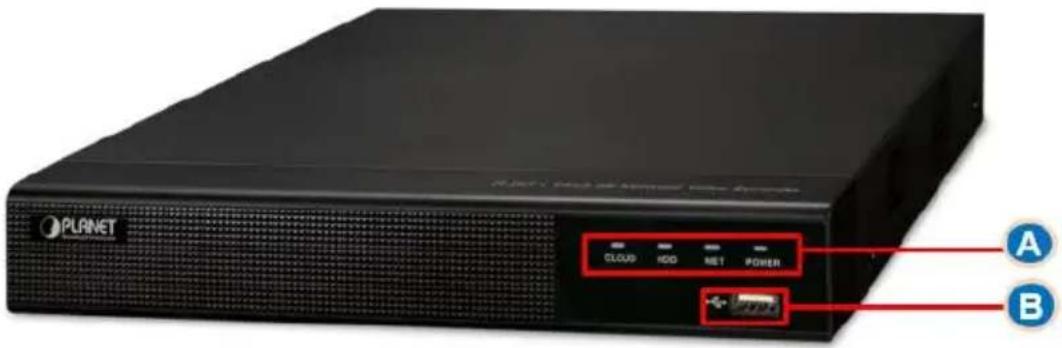
Figure 2-1
| No. | Name | Description |
| A | Power Indicator | The device is powered on normally |
| Network Indicator | Shows whether the device is properly connected to the network | |
| Hard disk Indicator | Shows whether the hard drive is connected properly | |
| Cloud Indicator | Shows whether the P2P function is enabled properly | |
| B | USB2.0 | Connect mouse or USB memory stick backup |
2.2 Rear Panel
The schematic diagram of the rear panel of the NVR-1600 is as follows:
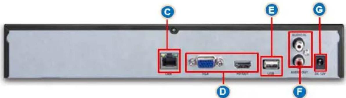
Figure 2-2
The corresponding description of each interface in Figure 2-2 is shown in the following table:
| No. | Name | Description |
| C | Ethernet port | 1 10/100/1000BASE-T MDI/MDI-X portConnect Network |
| D | HDMI Video Output | Connect HDMI display devices such as computer monitors |
| VGA | Connect VGA display devices such as computer monitors | |
| E | USB port | Connect the mouse, U disk or removable hard disk |
| F | Audio Input | Equipment audio input interface |
| Audio output | Equipment audio output interface | |
| G | Power Connector | DC External 12V, 2A Power AdapterDevice power connector |
Table 2-1
2.3 Mouse Description
Operate NVR through mouse left button, right button and scroll wheel.
| Mouse actions | Function |
| Click left mouse button | 1. Select one of the options2. Insertion cursor, enter or modify the value of a parameter3. During playback, click the timeline to switch the playback progress. |
| Click right mouse button | 1. When interface not locking, click right mouse button, system menu pops up2. When interface locking, click right button on real-time preview interface, login interface pop up3. Click the right mouse button on the submenu, return to the previous menu |
| Double-click the mouse left button | In the preview and playback state, switch between single screen and multi screen. |
| Mouse drag | 1. In the pan/tilt control state, the direction is rotated.2. In the video occlusion alarm and motion detection alarm area settings, set the area range.3. Drag the area of the electronic zoom.4. In the preview interface, select a channel and press and drag to switch to other channel locations.5. When playing back the video, drag the progress bar to switch the video file to be played. |
| Slide mouse scroll wheel | 1.Time setting2.Select the drop-down menu values3. When previewing, you can switch the preview channel.4. When zooming in electronically, you can zoom in and out of the video image. |
Table 2-2
2.4 Input Method Introduction
Input method includes lowercase and uppercase English letters. Clicking " ", button on the left can switch the input method and the symbol " " represents deleting incorrect input, as shown in Figure 2-3 and Figure 2-4.
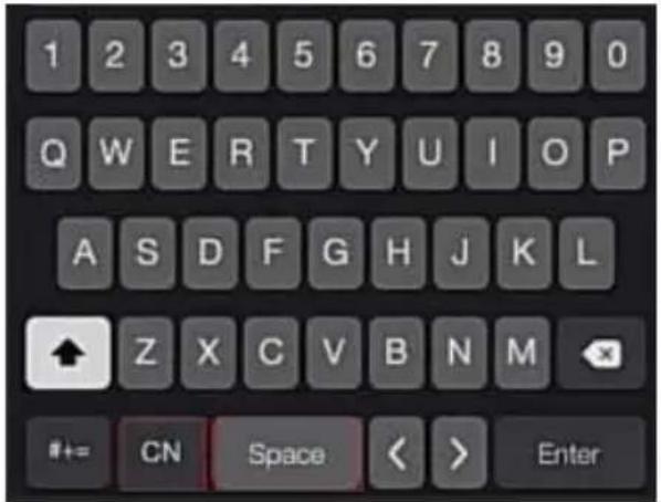
Figure 2-3 Uppercase English input
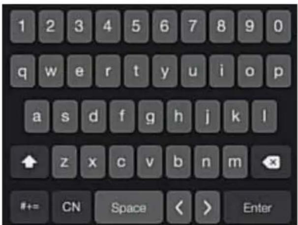
Figure 2-4 Lowercase English input
Chapter 3 Connecting NVR
3.1 Hard Disk Installation

CAUTION
- Before installation, please confirm that the power has been disconnected.
- Please use the NVR dedicated monitor hard drive recommended by the device manufacturer.
Installation tools
A Phillips screwdriver
Hard disk installation
The hard disk is installed as shown in Figure 3-1.
(1) Unscrew the cover to open the cover.
(2) Connect one end of the hard disk data cable and power cable to the motherboard, and connect the other end to the hard disk.
(3) Turn over the chassis, mount the hard disk in the indicated position and screw it tightly.
(4) Now turn over the chassis again and cover it with screws.
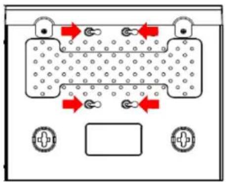
flowchart
graph TD
    A["Top Tank"] --> B["Left Tank"]
    B --> C["Right Tank"]
    C --> D["Bottom Panel"]
    style A fill:#f9f,stroke:#333
    style B fill:#ccf,stroke:#333
    style C fill:#cfc,stroke:#333
    style D fill:#fcc,stroke:#333
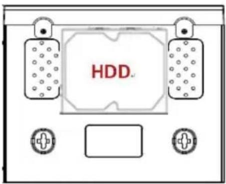
Figure 3-1 Hard Disk Installation
3.2 Device Connection
Use VGA cable or HDMI cable to transmit the NVR signal to the display as shown in Figure3-2.
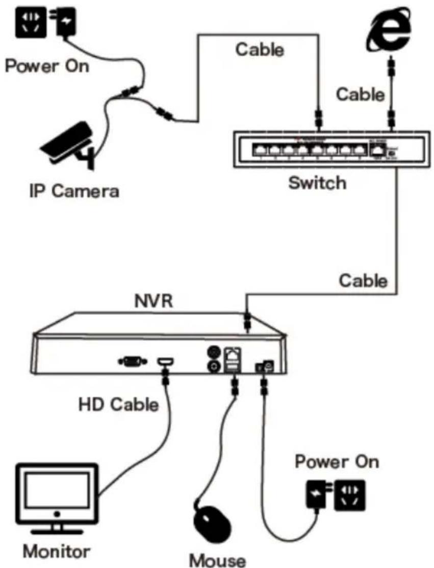
flowchart
graph TD
    A["Monitor"] -->|Power On| B["IP Camera"]
    B --> C["Cable"]
    C --> D["Switch"]
    D --> E["Cable"]
    E --> F["NVR"]
    F --> G["HD Cable"]
    G --> H["Mouse"]
    H --> I["Power On"]
    style A fill:#f9f,stroke:#333
    style B fill:#ccf,stroke:#333
    style C fill:#cfc,stroke:#333
    style D fill:#fcc,stroke:#333
    style E fill:#cff,stroke:#333
    style F fill:#ffc,stroke:#333
    style G fill:#cfc,stroke:#333
    style H fill:#fcc,stroke:#333
    style I fill:#cfc,stroke:#333
Figure3-2

CAUTION
● Devices with built-in PoE network ports support IPC plug-and-play functionality. When adding IP devices using the PoE network port plug-and-play method, make sure that the IP devices also support the PoE standard.
Chapter 4 NVR Startup
4.1 System Initialization
The steps to turn on NVR are as follows:
○1 Connect the device to the monitor and plug in the mouse and power cord.
○2 Turn on the power switch on the rear panel to start the device. The system initialization screen appears, as shown in Figure 4-1.

Figure 4-1

CAUTION
- Please confirm that the voltage to be connected matches the NVR requirements and ensure that the NVR ground is well grounded.
- If the power supply is abnormal, the NVR may not work properly or even damage the NVR. It is recommended to use a regulated power supply for power supply.

Note
After the device starts up, it can be simply configured through the boot wizard, which is the normal operation of the device.
4.2 Boot wizard
4.2.1 Quick Startup Wizard
Quickly configure the NVR as shown in Figure 4-2:
① Select the system language by drop down menu on web upper right corner.
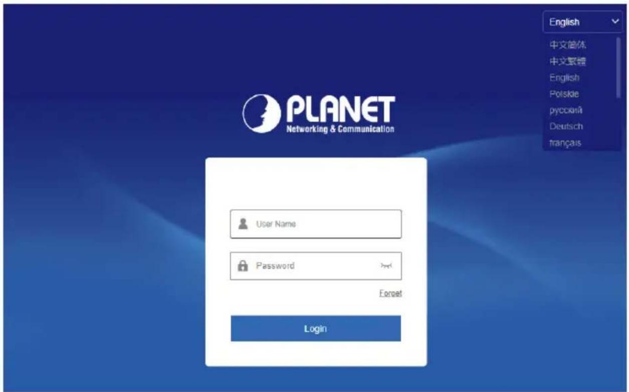
Figure 4-2 ①
② Then select a user, enter the password, select the system language and click "Login" to login the system (the default username is admin, and password is admin).
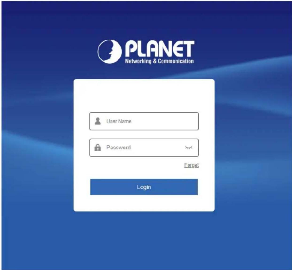
Figure 4-2 ②
③ Go to the "Date and Time" interface, configure the Device date and time, and click "Next".
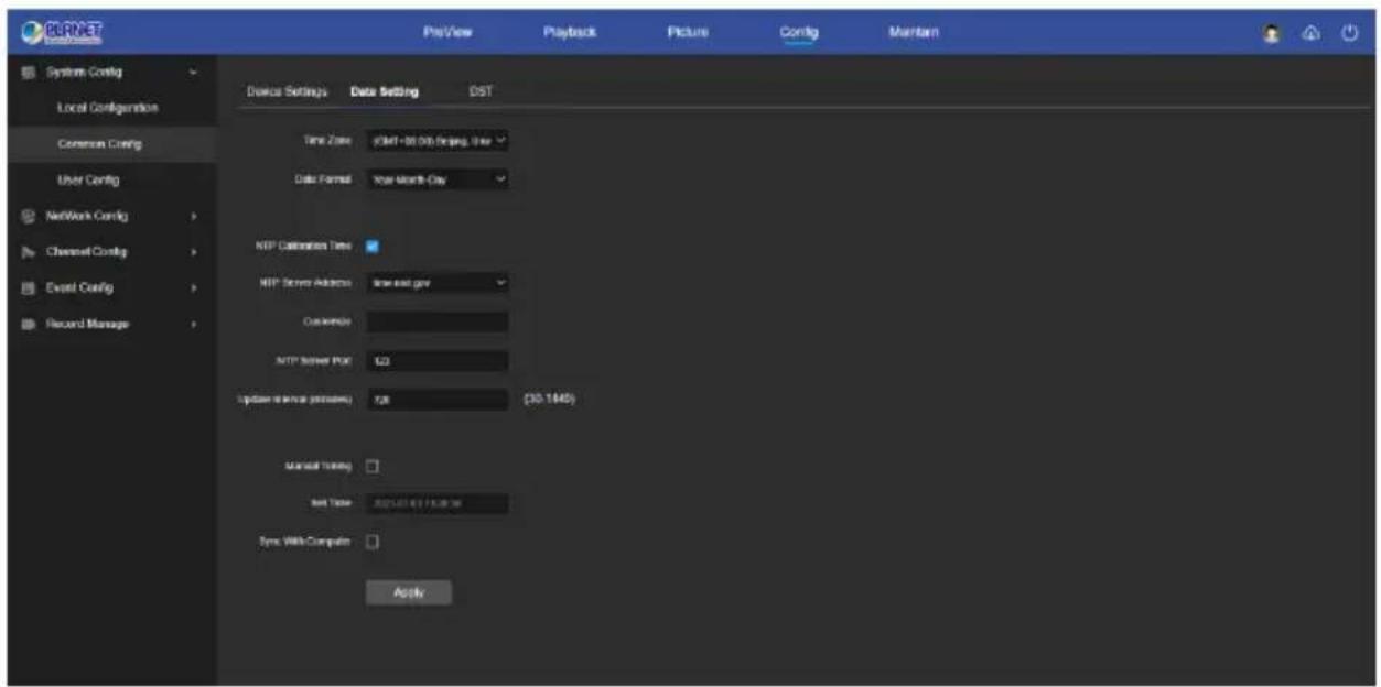
Figure 4-2 ③
④ Go to the "Network Setup" interface, configure the network parameters of the device. Click "Next".
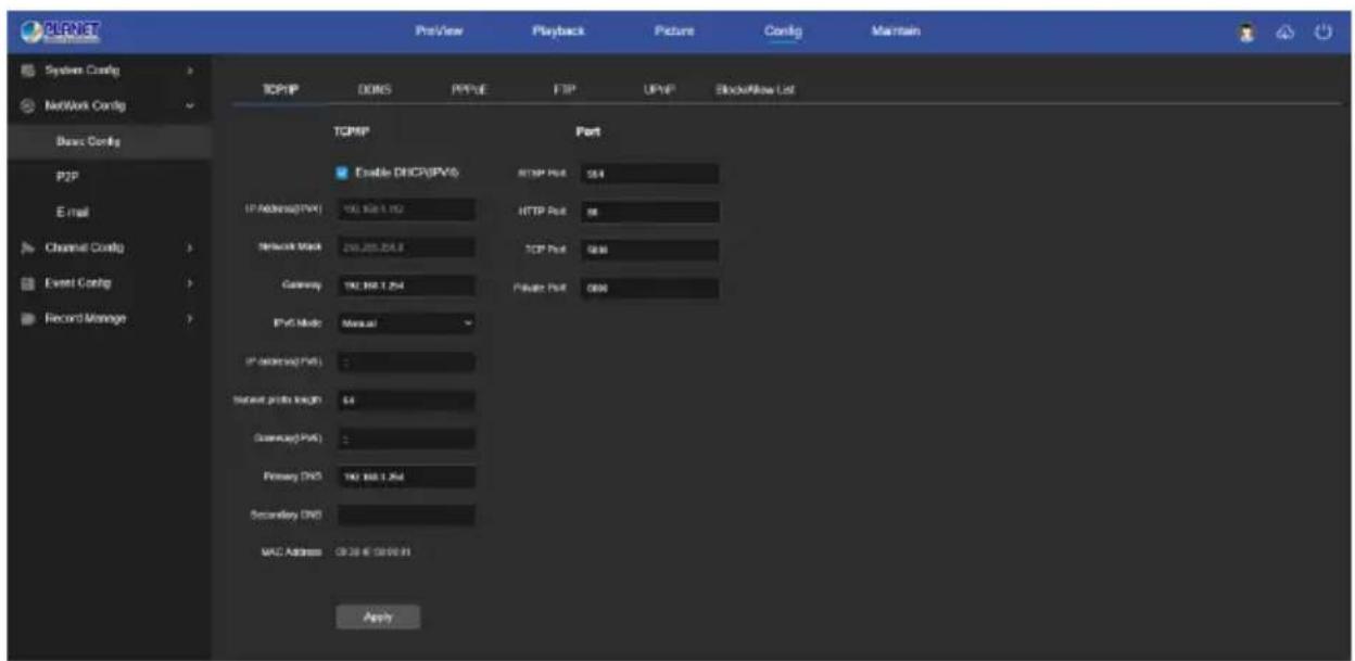
Figure 4-2 ④
⑤ Go to the "Camera" interface, you can search for and add devices and click "Next".
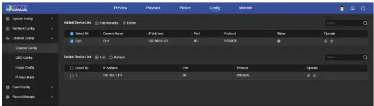
Figure 4-2 ⑤
⑥ Go to the "Hard Disk" interface, you can check the hard disk usage status: When the status shows "In Use", please click "Next". When the status shows "not mounted", select the hard disk, click "Format → Confirm", the device restarts, and the hard disk is formatted.
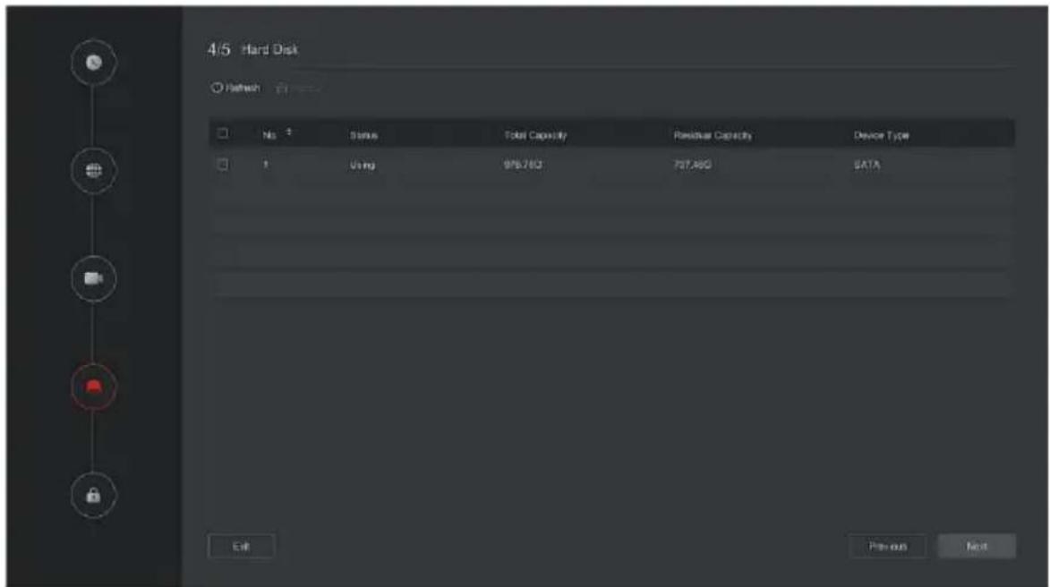
Figure 4-2 ⑥
⑦ Go to the "Change Password" interface, setting system password and security questions according to your actual needs, click "Complete", the boot wizard is set up.
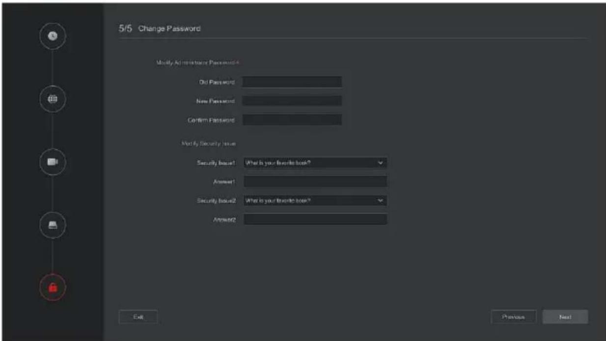
Figure 4-2 ⑦
 Note Note | ● On the startup wizard screen, click " Exit → Confirm " to exit the startup wizard.● When the password is too simple, after the login, a password strength security interface will pop up. You can click "Modify later" to continue using the existing password.● Any interface of the boot wizard, if you do not need to modify it, please click "Next" to enter the next interface directly.● Please confirm that the NVR device has been properly connected to the network before setting up the network parameters.● The hard disk needs to be formatted when it is first installed on the device. |
4.2.2 Forget Password
If you forget your password, you can click "Forget password" on the login page to enter the Forget Password interface to reset the password (as shown in Figure 4-3). There are three ways to reset the password: "Answer the question", "Import Key" and "Dynamic Password".
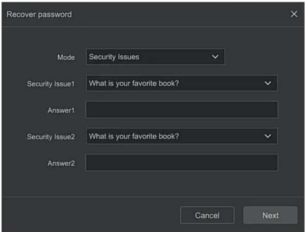
Figure 4-3
■ Answer The Question: Select the three security questions when setting the password and enter the answer to the corresponding question, click "Next Step" to enter the new password setting interface, as shown in Figure 4-4.
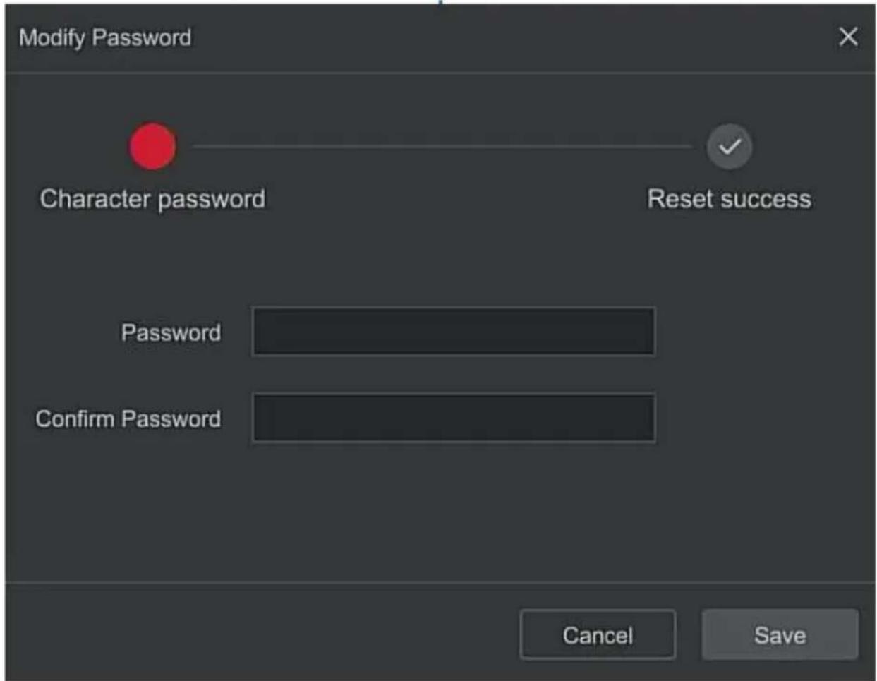
Figure 4-4
- Import Key: Select the authentication method as "Import Key", as shown in Figure 4-5.
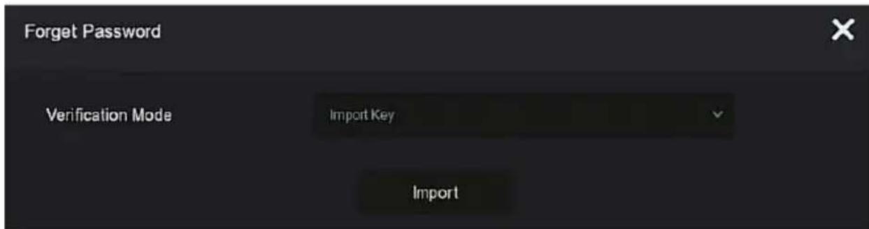
Figure 4-5
① Insert the USB disk (The key file is exported when the device setting password is stored.) on the device, and click "Import" to import the key file into the device.
② In the modification user interface, select "Change Password", enter a new password, confirm the password, and click "Save", as shown in Figure 4-6.
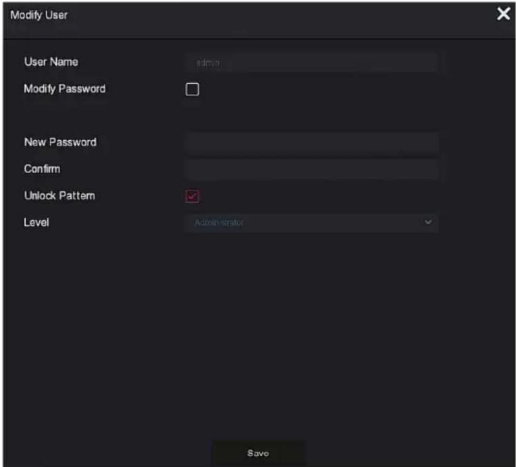
Figure 4-6
■ Dynamic Password: Select the authentication method as "Dynamic Password", as shown in Figure 4-7.
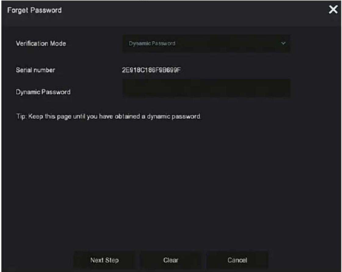
Figure 4-7
① Contact the supplier to get the security code. Enter the location of the security code, and click "Next Step".
② In the modify user interface, check "Change Password", enter a new password, confirm the password, and click "Save".

Note
- When selecting "Answer The Question", you must answer at least 2 questions, and the answer must be exactly the same as the set answer when setting the password before entering the "Modify User" interface.
- When you select "Import Key", the key file in the USB flash drive must be the key file exported by this device.
4.3 Preview Interface
After the system is fully booted, it will enter into the default preview interface, as shown in Figure 4-8.
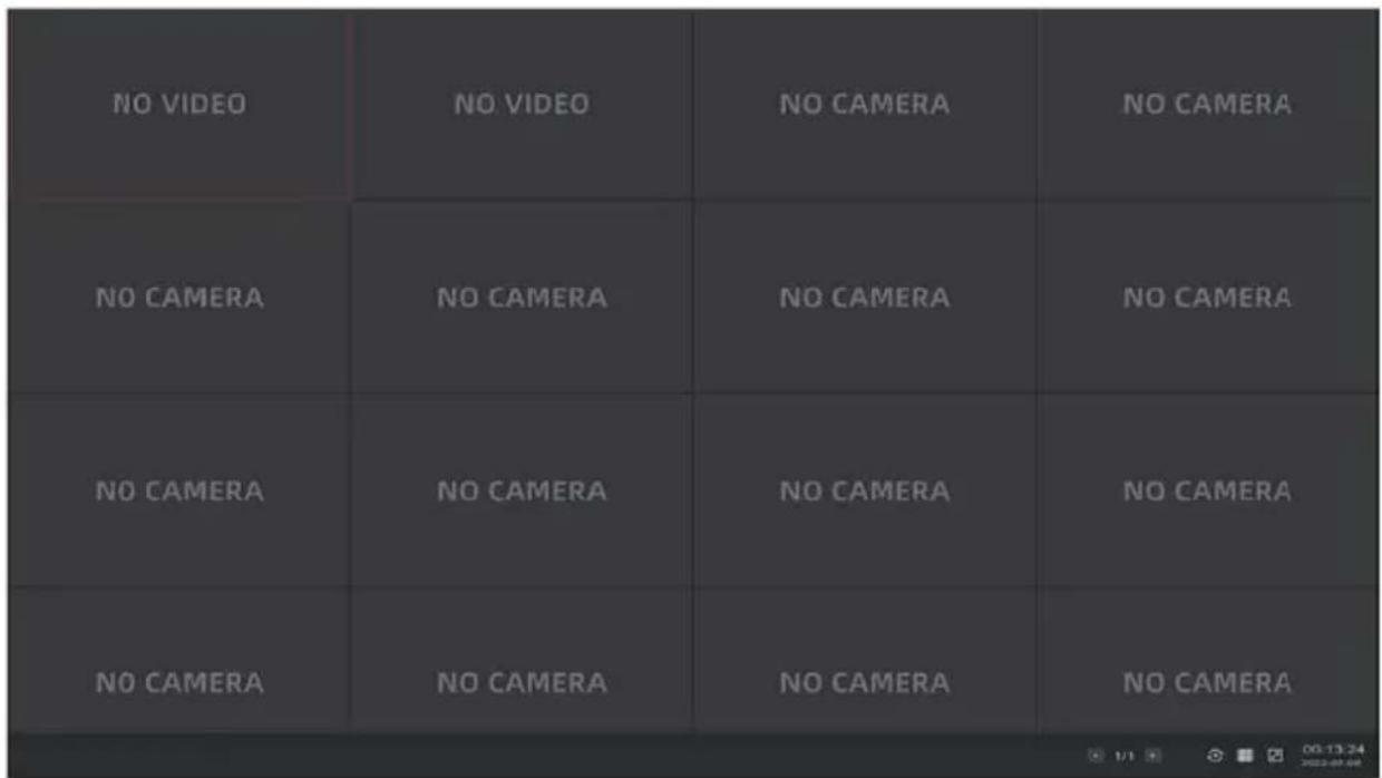
Figure 4-8
After the device normally starts up, the default setting is to preview in multi-screen display mode. Products with different channels has different amount of split screens to display. On the preview interface, you can set the appropriate date and time. On the bottom left of the screen, it shows the recording status of each video channel or alarm status icon.
The function of each icon is shown in the following table:
| Icon | Function |
 | The monitoring channel is in video. |
 | The monitoring channel is in the motion detection state. |
 | The monitoring channel is in the state of intelligent alarm. |
Table 4-1
4.4 Quick add device
Quick add device is shown in Figure 4-9:
① At the preview menu, for the channel of unconnected IP Camera, click "+" icon.
natural_image
Pure dark background with a small white plus sign in the center (no text or symbols)Figure 4-9 ①
② Select the device to add and click " " Add to add.
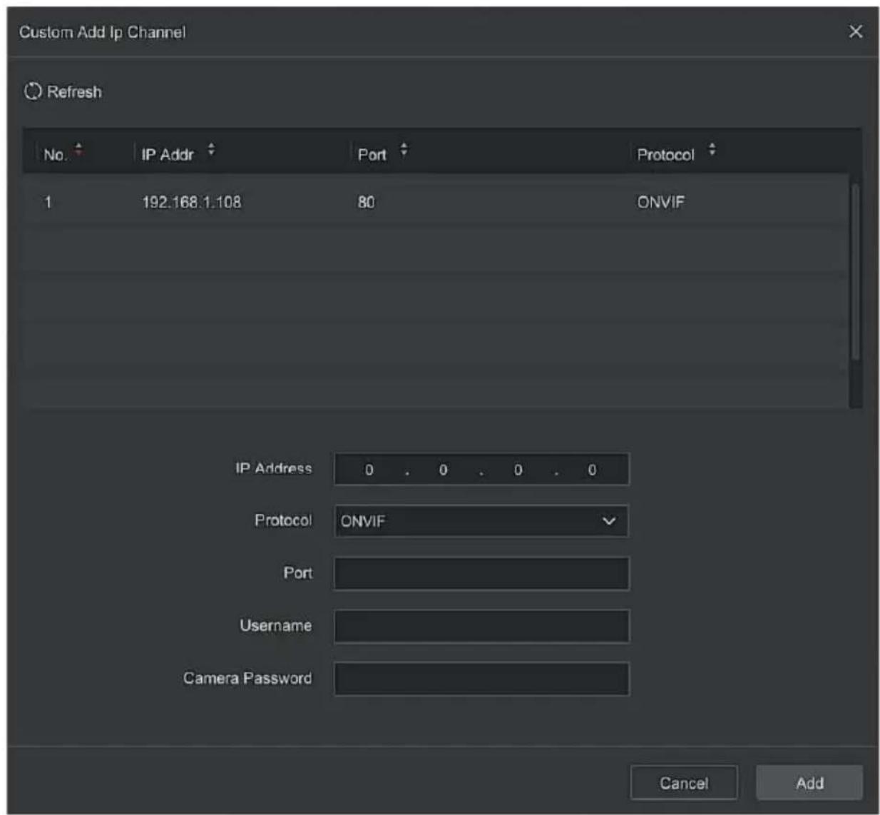
Figure 4-9 ②
Search: Click "Refresh" to automatically search all online IP devices in the LAN.
▶ Add: Add selected device.
Manual Add: On the Device Search interface, click "Manual add" → Click "Enable" → Select Protocol, Enter Password, IP, Port → click "Save".
Chapter 5 NVR Menu
5.1 Shortcut menu
After adding a device to a channel, click the channel. The shortcut menu appears as shown in Figure 5-1.
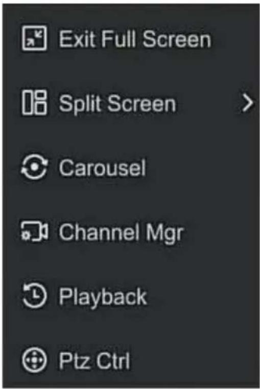
Figure 5-1
The shortcut menu icons and specific functions are shown in Table 5-1 below:
| Icon | Function | |
 | Exit Full Screen | |
 | The split screen is divided into 1, 4, 9, 16 split screen display according to the number of connected devices supported by the device | |
 | Click to open channel cruise | |
 | Click to enter the channel management interface, where you can add devices and manage devices | |
 | Click to enter the playback interface | |
 | Click to open the PTZ control interface to perform PTZ control operations | |
Table 5-1
5.2 Main Menu
After logging in to the system, click the right mouse button and select Exit Full Screen to enter the main menu interface. The main menu includes preview, playback, search, configuration, maintenance, alarm information, download, QR code, and power supply, as shown in Figure 5-2.
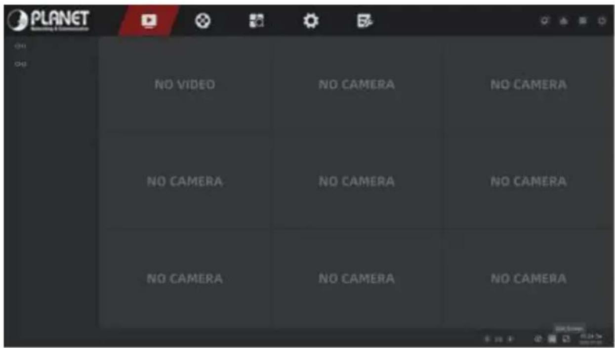
Figure 5-2
The main menu icons and specific functions are shown in Table 5-2 below:
| Icon | Function |
 | Click to enter the preview interface. (Detailed operation as 5.3.1) |
 | Click to enter the playback interface. (Detailed operation as 5.3.2) |
 | Click to enter the search interface. (Detailed operation as 5.3.3) |
 | Click to enter the config interface. (Detailed operation as 5.3.4) |
 | Click to enter the maintain interface. (Detailed operation as 5.3.5) |
 | Click to enter the alarm info interface. |
 | Click to enter the download interface. |
 | Click to view the QR code. |
 | Click to enter the logout user interface |
Table 5-2
5.3 Preview
In the main menu, click "to enter the preview interface, as shown in Figure 5-3:
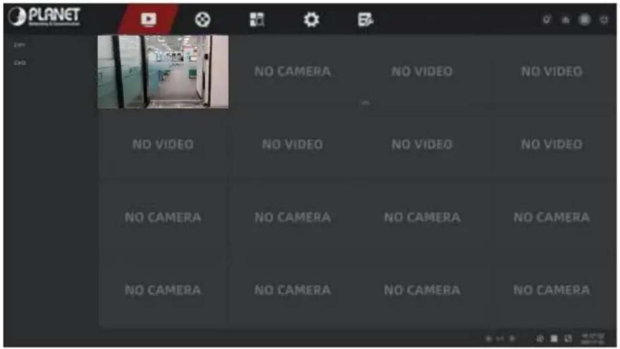
Figure 5-3
5.3.1 Channel shortcut menu
After adding a device to a channel, click the channel. The shortcut menu appears as shown in Figure 5-4.

Figure 5-4
The function of each icon is shown in the following table:
| Icon | Function |
 | Manual capture, click the button to capture the current video pictures. Search, view and backup pictures can be carried out in "Picture". |
 | Instant playback button, click the button, the channel playback 5 minutes before the video. |
 | PTZ, click into the PTZ interface |
 | Audio output control button, click to set the channel output volume and mute. |
 | Electronic zoom button, click to enter the full-screen zoom mode, display the unmagnified image of the channel in the lower right corner of the screen, and drag the red frame of the unmagnified image by mouse to switch the position of the enlarged image. Click "and " or scroll the mouse wheel to adjust the zoom. Click the right mouse button to exit the electronic zoom and restore the live preview interface. |
 | Image color button, click into the image interface, you can set the channel brightness, contrast, saturation, sharpness, fill light, exposure setting, white balance, video adjustment of the parameter values. |
 | Switch between main stream and sub stream |
Table 5-2
5.3.2 PTZ
Click " [icon] in the channel connected to PTZ to enter the PTZ setting interface, where you can perform operations such as PTZ speed, direction and zoom, as shown in Figure 5-5:
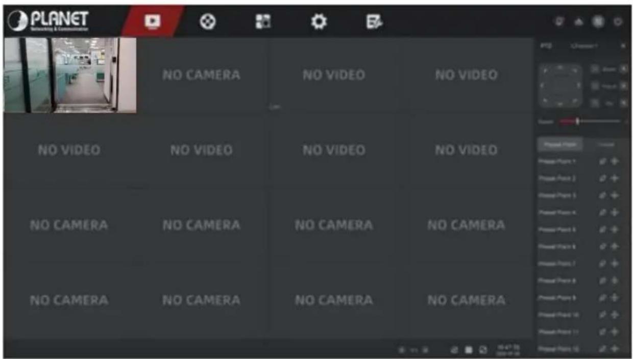
Figure 5-5
■ PTZ Control
PTZ control interface is used to set the PTZ direction rotation (including upper, lower, left, right, upper left, lower left, upper right and lower right) of the gimbal equipment, focusing, zooming, aperture, rapid positioning and cruising, etc., use with the direction keys when setting, as shown in Figure 5-5.
➢ Channel: The channel where the PTZ device is located.
Zoom: Click "+/-" to adjust camera zoom in/out.
Focus: Click "+/-" to adjust camera focusing.
Iris: Click "+/-" to adjust camera brightness.
Speed: To control the speed of the pan/tilt, for example, the rotation speed in step of 7 is much greater than the rotation speed in step of 1.
Direction: Use "■" to adjust the direction of the PTZ camera.
■ Cruise Control
In the PTZ setting interface, click "Preset Point" to enter the preset position setting interface, which is used to set and call the preset point, click "Cruise" to select the cruise line, turn on/off the cruise, as shown in Figure 5-6:
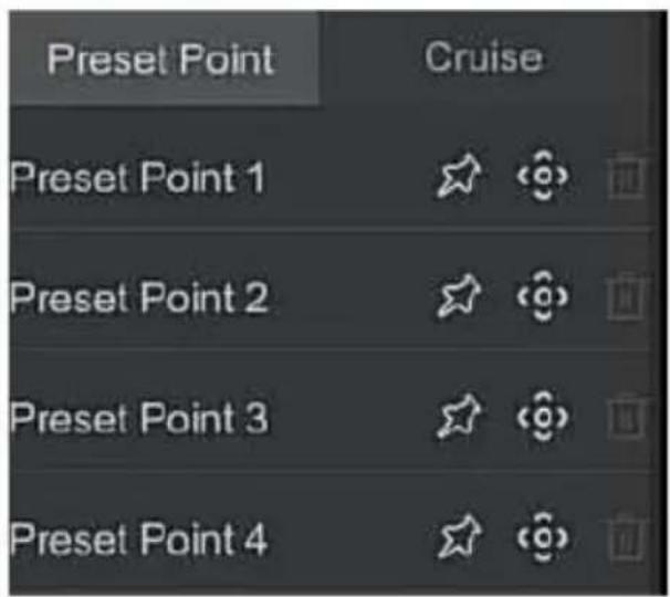
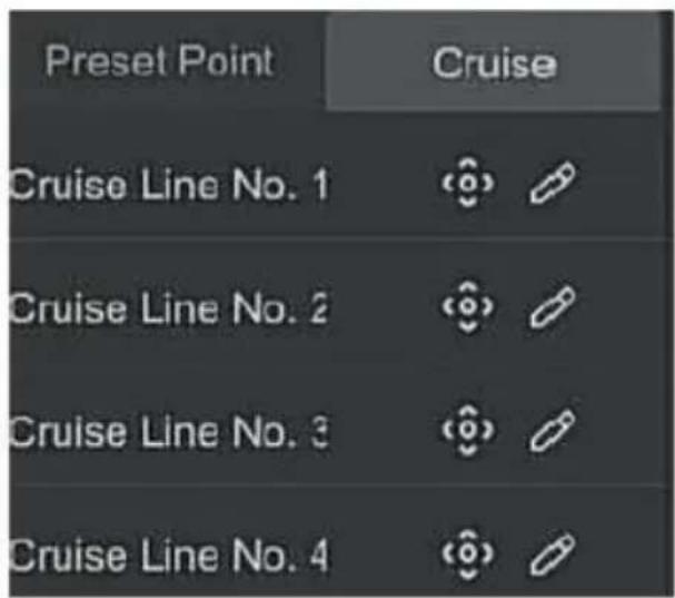
Figure 5-6
➢ Preset: Used to set/recall/delete presets.
➢ Cruise: Select the cruise line that has been set and click to turn on/off cruise.
5.3.3 Image Configuration
In the image configuration interface, you can set the image parameters such as brightness, contrast, saturation, sharpness, etc.
The steps for image setup are as follows:
Step 1: Click "图片" from the IPC channel to enter the channel image color setting interface, as shown in Figure 5-7.
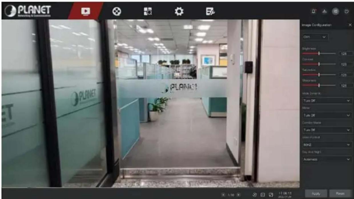
Figure 5-7
Step 2: Select the configuration channel.
Step 3: Set image brightness, contrast, saturation, sharpness, wide dynamic, mirroring, corridor mode, video format, day and night switching and other parameters according to actual needs.
Step 4: Click "Apply" to save the settings.
Image adjustment: According to the actual environment, you can Adjust the brightness, contrast, saturation and sharpness of the preview screen by dragging the progress bar. You can also set the value behind the progress bar, "Brightness", "Contrast", "Saturation", "Sharpness". Valid values range from 0-255 and the default value is 128.
Wide Dynamic: The default is turn off, WDR intensity (low, medium, high) can be toggled in the drop-down menu.
Mirror: The default is turn off, Switch modes (horizontal, vertical, horizontal and vertical) as needed.
Corridor Mode: The default is turn off, Switch modes according to actual needs (rotate 90^ , rotate 270^ ).
Video Format: The default is 50HZ(PAL), Switchable 60HZ(NTSC).
Day And Night: The default is auto, Modes can be switched according to actual needs (day, night, timing switching).
√ Day: The fill light of the camera is turned off, and the picture remains in color mode.
√ Night: The fill light of the camera is always on.
√ Timing: The fill light of the camera is turned on or off according to the present time.

Note
The camera image interface only displays the device support functions. The specific interface is subject to the actual product.
5.4 Playback
5.4.1 Playback channel video
In the main menu, click "to" enter the video playback interface, as shown in Figure 5-8.
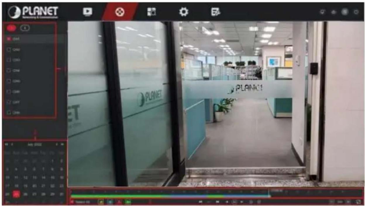
Figure 5-8
The interface description is shown in the following table:
| No. | Function | Description |
| 1 | Channel | Min / Max Ch:Intelligently select the number of playback channels. The minimum number of channels selects one channel at a time by default; the maximum number of channels selects the maximum channels supported by the device at a time, such as 4 channels.Channel:select the channel number to be queried(multiple channels can be selected at the same time, depending on the device performance) |
| 2 | Calendar | Dates with colored dots on the calendar indicate that there is video recording, and dates without color dots indicate that there is no recording on that day. In any playback mode, select the recording type and channel, click the date you want to view, and the timeline will be updated to the recording track of the day. |
| 3 | Playback control area |  : Motion Detection : Motion Detection : Smartssssslarm : Smartssssslarm : Normal[BY2Y] : Deceleration : Normal[BY2Y] : Deceleration : Acceleration : Acceleration : Frame rewind : Frame rewind : Frame advance : Frame advance : Play : Play : Pause : Pause : Go back 30 seconds : Go back 30 seconds : Fast forward 30 seconds : Fast forward 30 seconds :Full Screen :Full Screen |
| 4 | Play bar | Display the recording type and the time period under the current conditions. When the device is in multi-split screen, click the playback interface and select a channel. The first time axis is the recording time axis of the selected channel. Click a point in the colored area with the mouse to start playback from that point in time. |
| 5 | Menu hide | [yGYW] : Electronic zoom : Turn volume on / off[z8W6] : Add tags : Turn volume on / off[z8W6] : Add tags : Clip : Clip |
Table 5-4
■ Playback
Retrieve the corresponding video files according to the channel, date and video type, and play the video files in sequence from the playback bar that meets the conditions.
The specific steps are as follows:
Step 1: In the main menu, click "☐" to enter the playback interface.
Step 2: Select the video playback channel, and the calendar will automatically display the current month's video recording.
√ Single channel Playback
- Select the channel, date and recording type to be played back.
- Click "and the display interface starts to playback the recording, as shown in Figure 5-9 below.
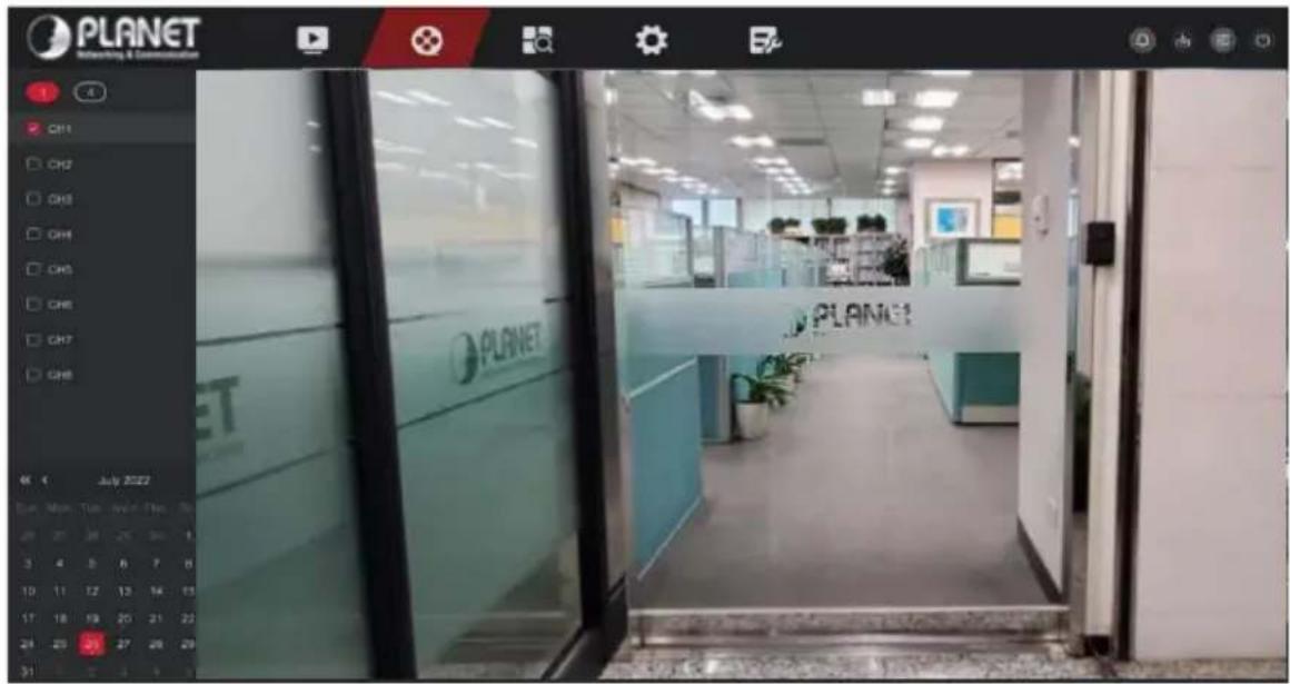
Figure 5-9
√ Multi-channel playback
- Select multiple channels, date and recording type to be played back.
- Click "播放", the display interface starts multi-channel synchronous playback video, as shown in Figure 5-10 below.
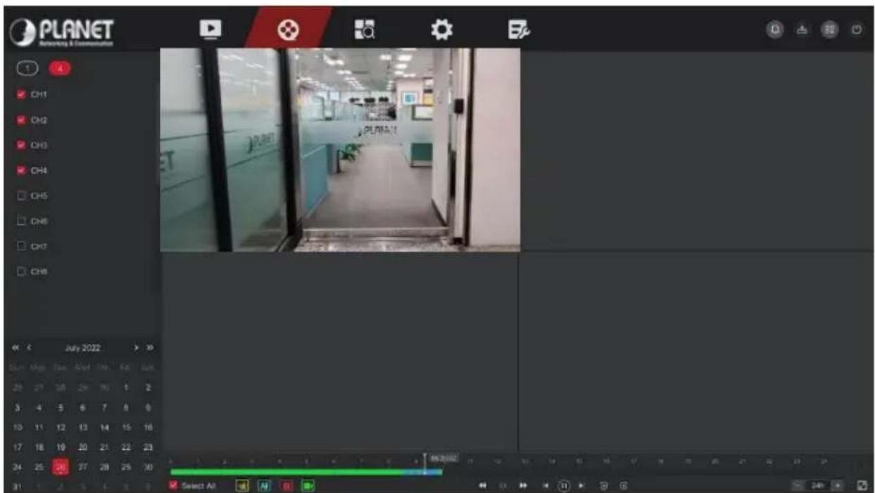
Figure 5-10
5.4.2 Playback assistance function
■ Electronic zoom
The specific operation steps are as follows:
Step 1: In the main menu, click "☐" to enter the video playback interface.
Step 2: Select the channel for video playback and the date when the video is recorded, and the searched video will be displayed on the progress bar.
Step 3: Click "☐" to playback on the display interface.
Step 4: Click playback interface, popup hidden menu, and click "⊕" to enter electronic zoom interface, as shown in Figure 5-11 below.
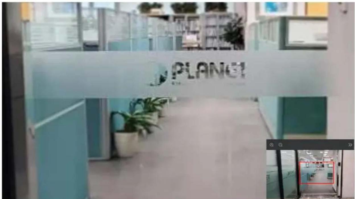
Figure 5-11

Note
- Enter the Electronic zoom interface, the default image is enlarged; the maximum magnification of the image is 16 times.
- When enlarging an image, the center of the image is enlarged by default. Hold down the left mouse button and drag the image to switch to the area to be enlarged.
- You can use the mouse wheel to zoom in and zoom out the image. The mouse wheel slides down to enlarge the image; slides up to reduce the image.
Tag
The tag function can help users record relevant information at a certain point in time when playing back videos, so that they can view these marked videos at any time.
Step 1: In the main menu, click "☐" to enter the video playback interface.
Step 2: Select the channel for video playback and the date when the video is recorded, and the searched video will be displayed on the progress bar.
Step 3: When viewing the video, if there is an abnormal situation on the screen, you can click the playback interface window to pop up the hidden menu, click the label, and after adding a custom label, you can enter the label in the search interface to quickly view or export the corresponding video file, as shown in Figure 5-12 below.
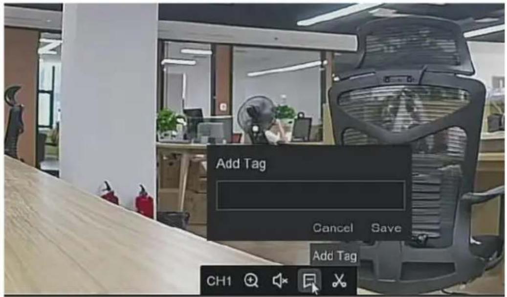
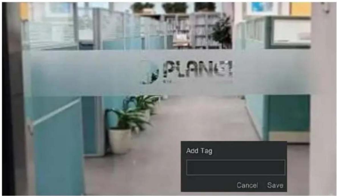

Note
- After adding the tag, the system will automatically clip and save the 10 second video before and after the tagging time.
■ Clip
It supports clip video files during video playback.
The specific operation steps are as follows:
Step 1: In the main menu, click "☐" to enter the video playback interface.
Step 2: Select the channel for video playback and the date when the video is recorded, and the searched video will be displayed on the progress bar.
Step 3: Click the playback window to pop up the hidden menu, click "☐", and enter the start time and end time in the pop-up box, as shown in
Figure
5-13.
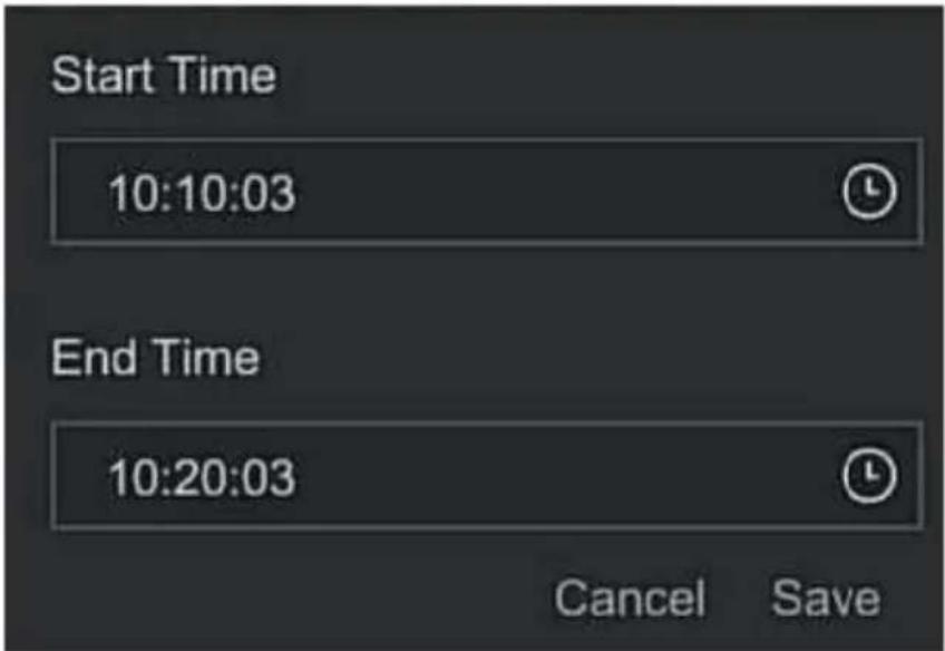
Figure 5-13
Step 4: Click "Save" to export clips to USB flash drive, as shown in Figure 5-14 below.
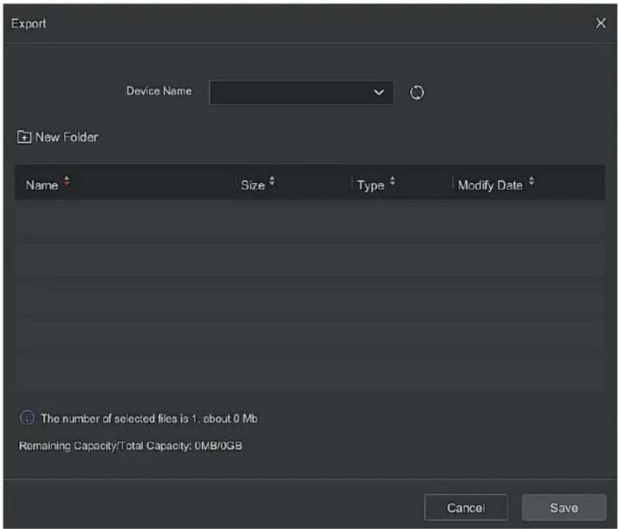
Figure 5-14
5.5 Search
5.5.1 Video
The specific operation steps are as follows:
Step 1: On the main menu page, select "Search → Video" to enter the video search interface, as shown in Figure 5-15 below.
Step 2: Set the search conditions (video type, time range, channel).
Step 3: Click "Search", the search results will show files that meet the conditions.
Step 4: Export the video file, insert the U disk into the NVR, select the video file, click "Export" or "Export All", wait for the export progress to complete, and then export the searched video files to the U disk.
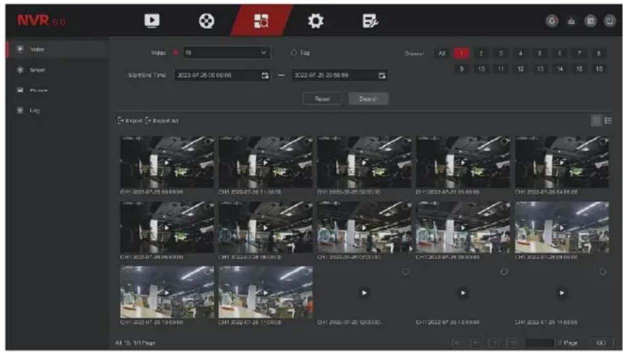
Figure 5-15
Video: Choose to find the video file type, there are normal events, motion detection, alarm types.
Tag: Select a tag, and then enter the tag content to find matching video files according to the tag content.
▶ Channel: Select the channel.
➢ Start/End Time: Select the start and end time of the search file.
Search: Search for video files by search criteria and display them in a list.
➢ Export: Custom selection of video files for exporting stored on a USB
stick connected to the device.
Export All: Export all video files in the device and store them on the U disk connected to the device.
- / : Page turning function, when the system has many video files in the query time period, click to view other video files.
: Files are displayed in view.
: Files are displayed in a list.
5.5.2 Smart
The specific operation steps are as follows:
Step 1: On the main menu page, select "Search → Smart" to enter the smart event search interface, as shown in Figure 5-16 below.
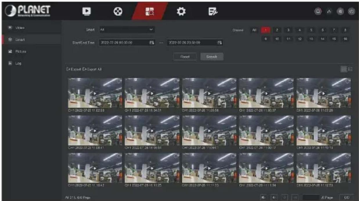
Step 2: Set the search conditions (smart event type, time range, channel).
Step 3: Click "Search", the search results will show files that meet the conditions.
Step 4: Export the video file, insert the U disk into the NVR, select the video file, click "Export" or "Export All", wait for the export progress to complete, and then export the searched video files to the U disk.
Smart: Choose to find the video file type, there are regional detection, line crossing, loitering, people gathering detection.
▶ Channel: Select the channel.
Start/End Time: Select the start and end time of the search file.
Search: Search for video files by search criteria and display them in a list.
Export: Custom selection of video files for exporting stored on a USB stick connected to the device.
Export All: Export all video files in the device and store them on the U disk connected to the device.
: Page turning function, when the system has many video files in the query time period, click to view other video files.
: Files are displayed in view.
: Files are displayed in a list.
5.5.3 Picture
The specific operation steps are as follows:
Step 1: On the main menu page, select " Search → Smart " to enter the smart event search interface, as shown in Figure 5-17 below.
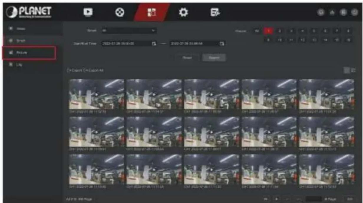
Step 2: Set the search conditions (smart event type, time range, channel).
Step 3: Click "Search", the search results will show files that meet the conditions.
Step 4: Export the video file, insert the U disk into the NVR, select the video file, click "Export" or "Export All", wait for the export progress to complete, and then export the searched video files to the U disk.
Picture: Choose to find the picture file type, there are manual, motion detection, alarm, regional detection, line crossing, loitering, people gathering detection.
▶ Channel: Select the channel.
Start/End Time: Select the start and end time of the search file.
Search: Search for video files by search criteria and display them in a list.
Export: Custom selection of video files for exporting stored on a USB stick connected to the device.
Export All: Export all video files in the device and store them on the U disk connected to the device.
←/→: Page turning function, when the system has many video files in the query time period, click to view other video files.
: Files are displayed in view.
: Files are displayed in a list.
5.5.4 Log
The specific operation steps are as follows:
Step 1: On the main menu page, select " Search → Log " to enter the log search interface, as shown in Figure 5-18 below.
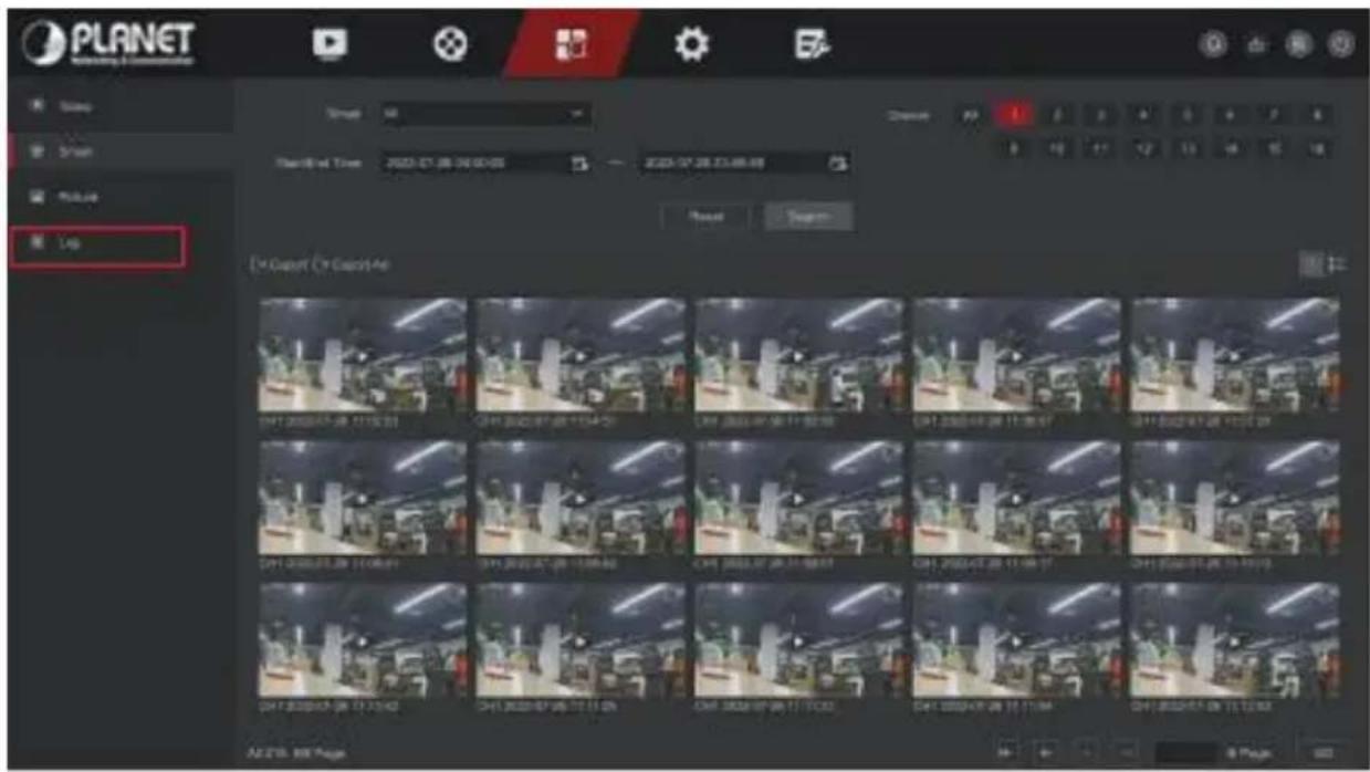
Figure 5-18
Step 2: Set the search conditions (log type, time range).
Step 3: Click the "Search" button to view the log.
Step 4: Export the log file, insert the U disk into the NVR, click "Export All", wait for the export progress to complete, and then export the searched log files to the U disk.
Log: Choose to find the log file type, there are system management, user management, parameter configuration, file operations, status prompt, alarm event.
➢ Start/End Time: Select the start and end time of the search file.
Search: Search for picture files by search criteria and display them in a list.
Export All: Export all log files in the device and store them on the U disk connected to the device.
← / → : Page turning function, when the system has many log files in the query time period, click to view other log files.
5.6 Config
Config is composed of easy mode and expert mode.
5.6.1 Easy Mode
5.6.1.1 System Config
■ Common Config
In the system config interface, click "Config → Easy Mode → System Config → Common Config" to enter the common configuration interface, where you can set the system time, resolution, enable/disable boot wizard, operation password, and NTP time synchronization, as shown in Figure 5-19:
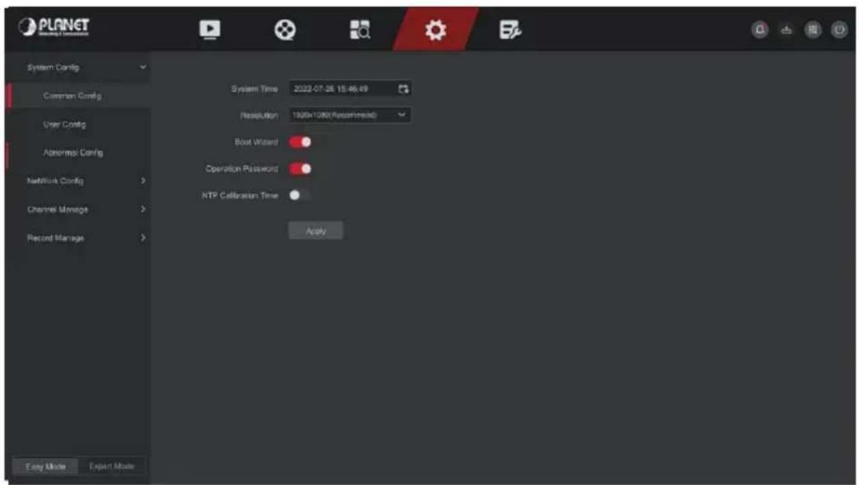
Figure 5-19
System Time: Display the time of the current device, click the time display bar to pop up the calendar and time bar, you can manually modify the system time, turn on the NTP time calibration and then turn it to gray.
Resolution: Displays the resolution of the current device output, the selectable values are 1024×768, 1280×720, 1280×1024, 1920×1080, 3840×2160 NVR HD high-definition interface supports maximum 4K resolution output.
Boot Wizard: It is enabled by default, and it will directly enter the "Startup Wizard" interface every time it is turned on. Click " " to close the startup wizard.
Operation Password: It is enabled by default. Click " 🔍" to disable the operation password. You can enter the system without entering a password when using it.
NTP Calibration Time: It is disabled by default. Click " " to enable NTP time calibration.
■ User Config

Note
● The factory default administrator user name is admin and the password is admin.
- Administrators can add and delete users and configure user parameters.
- The user level has two levels, the Operator and the General user.

CAUTION
- In order to improve the security of the product's network use, please update the product password regularly. It is recommended to update and maintain it every 3 months. If you have high security requirements for the product environment, it is recommended to update the password monthly or weekly.
- It is recommended that administrators effectively manage device accounts and user permissions, delete irrelevant users and permissions, and close unnecessary network ports.
- Administrators should configure user rights appropriately, and recommend using custom users for management in daily maintenance.
■ Add User
The specific operation steps are as follows:
Step 1: In the main menu, choose "Config → Easy Mode → System Config → User Config" to enter User interface, as shown in Figure 5-20.
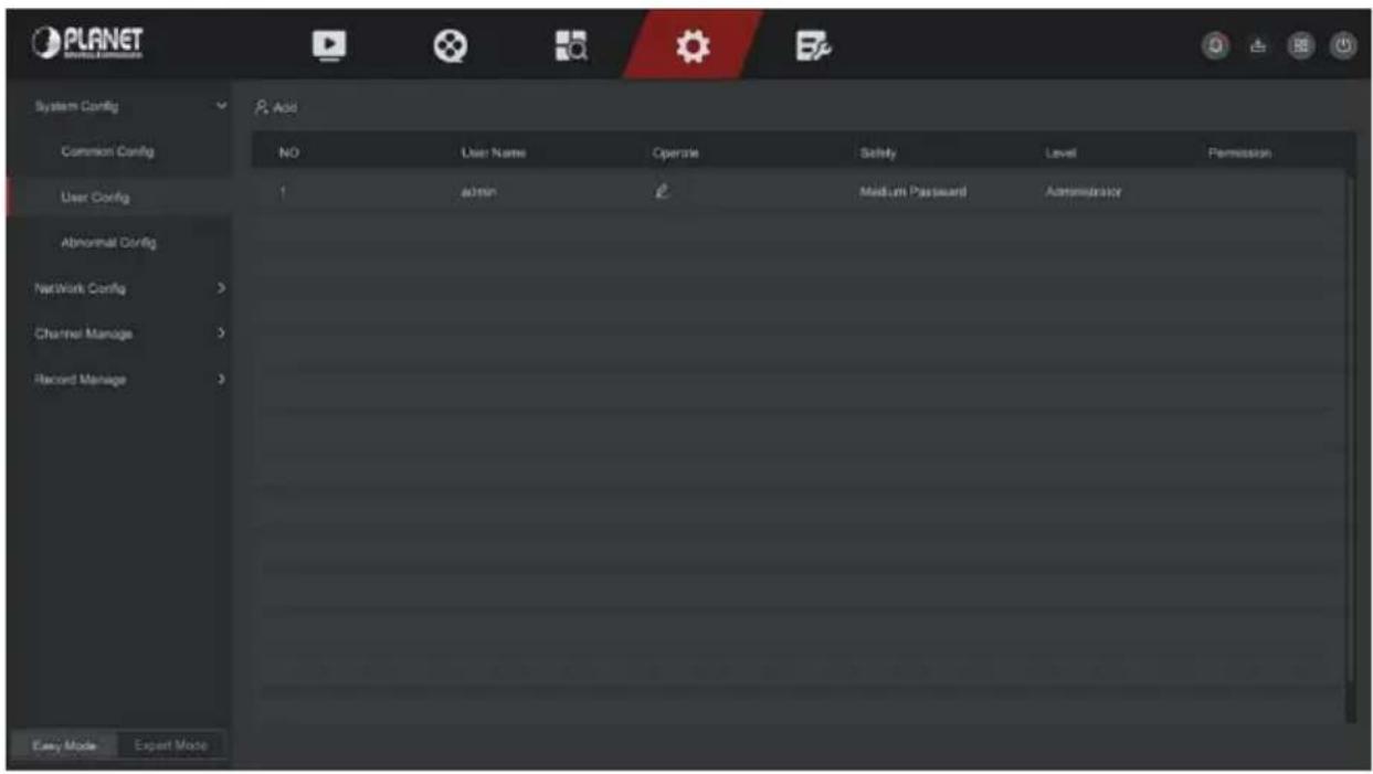
Figure 5-20
User list: Displays all current users of the device; the administrator can only change its password, not its permissions.
Step 2: Click "Add" to enter the permission confirmation interface, first confirm the password, as shown in Figure 5-21 below.
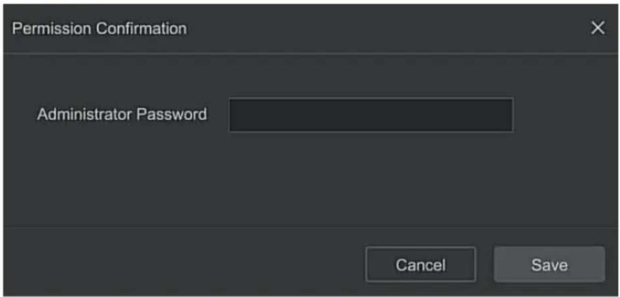
Figure 5-21
Step 3: Enter the administrator password, click "Save", after the permission is confirmed, you can enter the add user interface to add users, as shown in Figure 5-22 below.
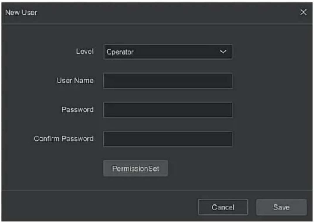
Figure 5-22
Step 4: Choose a level, enter the new user information (user name, password, confirm password), select the level, click "Save".
Step 5: Setting permissions. Click the "Permission Set" button to enter the permission setting interface, and set the user permission.
▶ Authority Description
Authority are divided into local configuration, remote configuration, channel configuration, administrator users can enable / disable corresponding permissions as needed.
- Local Config
√ Local Param Setup: set parameters, restore default parameters, import / export parameters.
√ Local Channel Setup: Add, delete, modify, import and export configuration files for the IP channel.
√ Local User: Check the User Management interface.
√ Local Disk: View and set recording plans, format storage devices.
√ Local Log: View system logs, system information.
√ Local Update: Upgrade the device locally.
√ Local Restore Default: you could restore default parameters.
√ Local Shutdown Reboot: You can shutdown and reboot the device.
- Remote Config
√ Remote Param Setup: Set parameters remotely, restore default parameters, import / export parameters.
√ Remote Channel Setup: Add, delete, modify IP channels remotely.
√ Remote User: View the User interface remotely.
√ Remote Disk: View and set recording plans, format storage devices remotely.
√ Remote Log: View system logs remotely.
√ Remote Update: Upgrade the device on the web.
√ Remote Restore Default: you could restore default parameters remotely.
√ Remote Shutdown Reboot: you can shutdown and reboot the device remotely.
- Channel Config
√ Local Preview: Preview live video of each channel locally, this permission is detailed for each channel.
√ Remote Preview: Preview live video of each channel remotely, this permission is detailed for each channel.
√ Local Record: Set the recording plan of each channel locally, this permission is detailed for each channel.
√ Remote Record: Set the recording plan of each channel remotely, this permission is detailed for each channel.
√ Local Playback: Playback video files on NVR locally, this permission is detailed for each channel.
√ Remote Playback: Remote playback, download video files on NVR, this permission is detailed for each channel.
√ Local PTZ: this permission is detailed for each channel.
√ Remote PTZ: this permission is detailed for each channel.
√ Local Backup: Backup video files on NVR locally, this permission is detailed for each channel. Channels with local backup authority must have local playback authority.
√ Remote Backup: remote backup the video files from NVR, this permission is detailed for each channel. A channel with remote backup authority must have remote playback authority.

Note
- Only the admin administrator has the right to "restore default parameters".
- Channel permissions support individual permission settings for a channel.
Step 6: Click "Save" to save the set permissions and return to the user management interface, as shown in Figure 5-23 below.
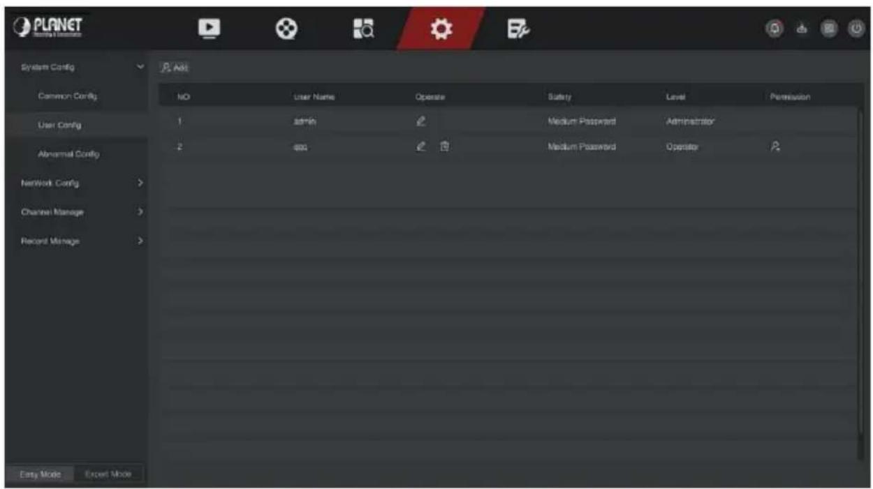
Figure 5-23
■ Modify the user
The specific operation steps are as follows:
Step 1: In the main menu, choose "Config → Easy Mode → System Config → User Config" to enter User interface.
Step 2: Choose User, click " " to enter Modify User interface, as shown in Figure 5-24 below.
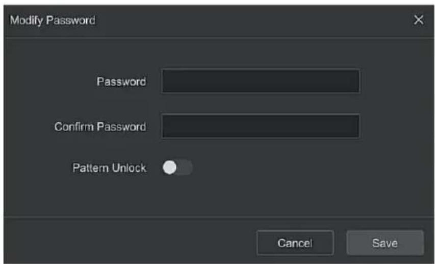
Figure 5-24
Step 3: Modify user's password as needed, click "Save".

- When administrator changing the password, an unlock pattern can be set at the same time, and the user will have one more way to login to the device.
■ Delete the user
The specific operation steps are as follows:
Step 1: In the main menu, choose " Config → Easy Mode → System Config → User Config " to enter User interface.
Step 2: Choose the user you want to delete, click the corresponding" below to delete it.
Step 3: Enter the administrator password, click "Save" to complete user deletion.
■ Modify the user permission
The specific operation steps are as follows:
Step 1: In the main menu, choose "Config → Easy Mode → System Config → User Config" to enter User interface.
Step 2: Choose the user, click ", enter the administrator password to enter the interface for modifying user permissions, as shown in Figure 5-25 below.
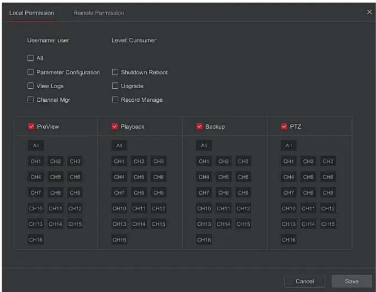
Figure 5-25
Step 3: Modify the user's local permissions and remote permissions as needed, and click "Save" to complete the modification.
■ Abnormal Config
Set the alarm mode of abnormal events. When an abnormal event occurs during the operation of the NVR device, the system executes the alarm linkage action. The event types supported by the device are "No Disk", "Disk Error", "Broken Network" and "IP Conflict".
The specific operation steps are as follows:
Step 1: In the main menu, choose "Config → Easy Mode → System Config → Exception" to enter Exception setting interface, as shown in Figure 5-26 below.
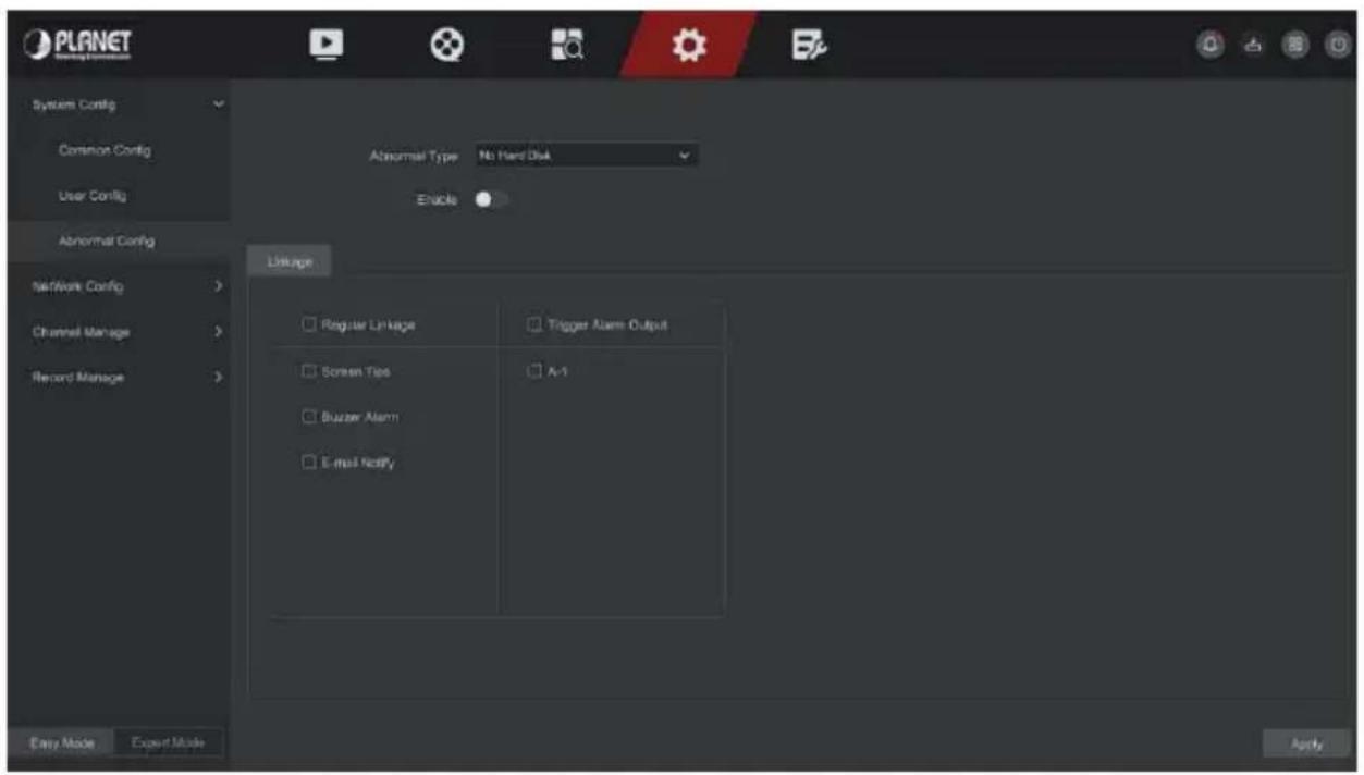
Figure 5-26
Step 2: Select the event type, click "to enable the exception alarm function, choose the way for linkage (Screen Display, E-mail Notification, Buzzer Alarm) and alarm output port.
Step 3: Click "Apply" to save the setting.
Screen Tips: When an alarm occurs, the device pops up an alarm screen to show a warning.
E-mail Notify: When an alarm occurs, the device will send an email as a warning.
➢ Buzzer Alarm: When an alarm occurs, the device will beep to show a warning.
5.6.1.2 Network Config
■ Basic Config
Set the IP address, DNS server and other information of the NVR device to ensure that it can communicate with other devices in the network.

- If the device is used for network monitoring, the network must be set up for normal use.
● Factory default IP: 192.168.0.20
The specific operation steps are as follows:
Step 1: In the main menu, click "Config → Network Config → Basic Config" to enter basic config interface, as shown in Figure 5-27 below.
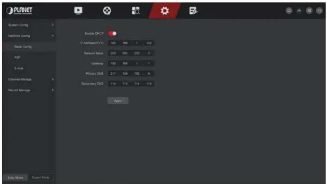
Figure 5-27
Step 2: Configure IP Address, Network Mask, Gateway, Primary DNS and other related network parameters.
Step 3: Click "Apply" to save the setting.
IP Address: Enter the IP address of NVR.
Enable DHCP: Enable / disable DHCP (Dynamic Host Configuration Protocol) function. "IP Address", "Network Mask", and "Gateway" can't be set when DHCP is enabled.
Network Mask: According to the actual situation set.
Gateway: According to the actual situation set, with the IP address in the same network segment.
Primary DNS: This is the DNS server IP address, which is usually provided by the local access point service provider (ISP). Enter the IP address of your domain name server here.
Secondary DNS: Start secondary DNS when the primary one does not work.

Note
- The IP address and the default gateway must be in the same network segment.
- If NVR enabled DHCP is in effect and you turn off DHCP, you cannot display the original IP information. You need to reset the IP address and other parameters.
P2P
P2P is a private network penetration technology. It does not need to apply for a dynamic domain name, perform port mapping, or deploy a transit server. You can directly scan the QR code to download a mobile client.
After registering an account, you can add and manage multiple IPC, NVR, XVR devices simultaneously on the mobile client.
You can add devices in the following two ways to manage multiple devices.
1) Scan the QR code for the mobile phone system, download the App and register the account. For details, see the App User Manual on the website.
2) Log on to the P2P platform, register an account, and add the device via the serial number.

- With this function, the device must be connected to an external network; otherwise it will not work properly.
The specific operation steps are as follows:
Step 1: On the main menu page, click "Config → Easy Mode → Network Config → P2P" to enter the P2P interface, as shown in Figure 5-28.
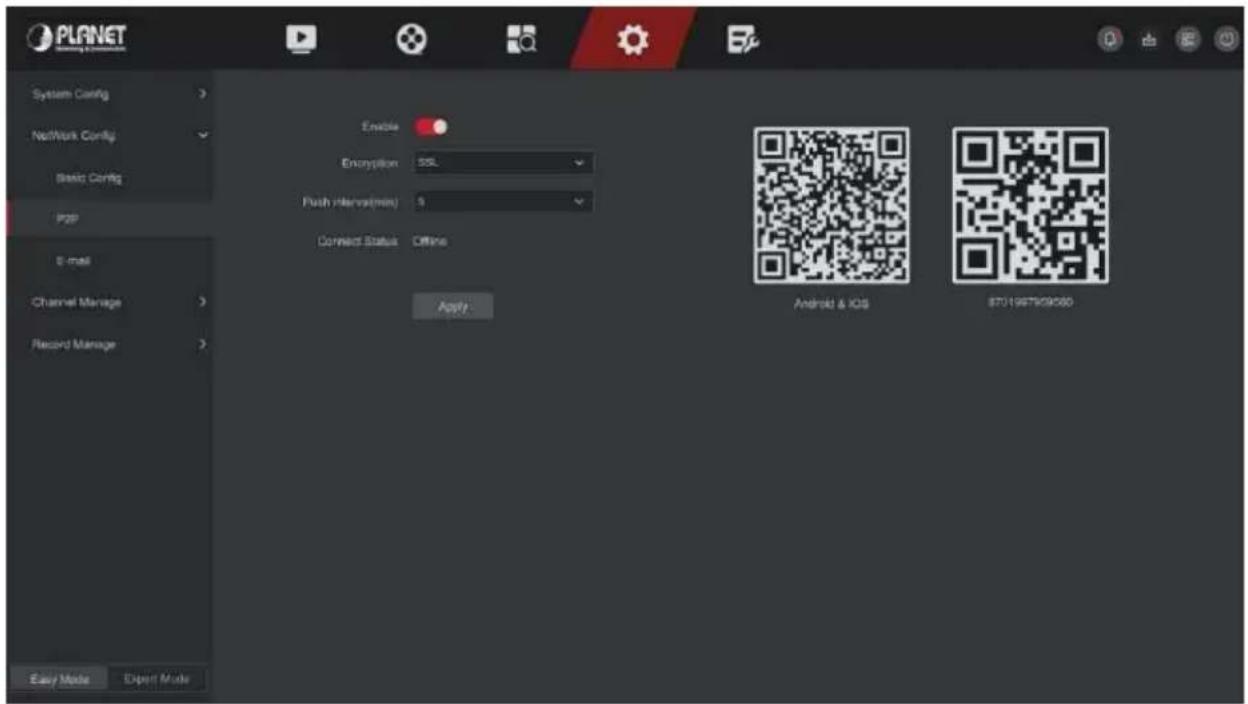
Figure 5-28
Step 2: Make sure that the NVR accesses the external network, choose "Enable P2P → Encryption".
Step 3: Click "Apply" to save the configuration.
Step 4: The connect status shows "Online". This indicates that P2P is enabled and can be used normally.
Connect Status: Display device P2P online status.
Enable: Turn on / off device P2P function, the default is "Online".
Encryption: Select the encryption type. After the device is enabled, all signaling communication between the device and the server is encrypted.
Push interval(min): Set the time interval for the device to snap the alarm picture to the mobile client, and you can also select "Turn off the push" to stop the device from pushing the picture to the mobile terminal.
Android &IOS: P2P client download link.
SN: Displays the serial number of the device P2P. This serial number is unique.
● BitVision App Client operation example
"BitVision App" provides a micro video service platform for home and business users. Users can easily view real-time video, historical video, alarm service and other services.
The specific operation steps are as follows:
Step 1: Use the Android or iOS phone to scan the corresponding QR code to download and install the BitVision App.
Step 2: Run the client and log in to the account (No account is required to register first).
Step 3: Add devices to the mobile client.
After login, click "Device Management → + → SN Add ", Align the QR code on the device body or P2P interface to scan → enter the device username, password and verification code after scan the QR code (the verification code printed on the label), click "Add" to set device note and group, click "Send" after add successfully.
Step 4: Real-time preview
In the main interface, click "Real Time → + " → choose the device you want to view the preview, click "Done", choose a channel to play the real time video.
After setting the email information and enabling the alarm linkage email function, when the NVR triggers an alarm, the system sends an alarm email to the user mailbox.
The specific operation steps are as follows:
Step 1: On the main menu page, click "Config → Network Config → E-mail" to enter the E-mail setting interface, as shown in Figure 5-29.
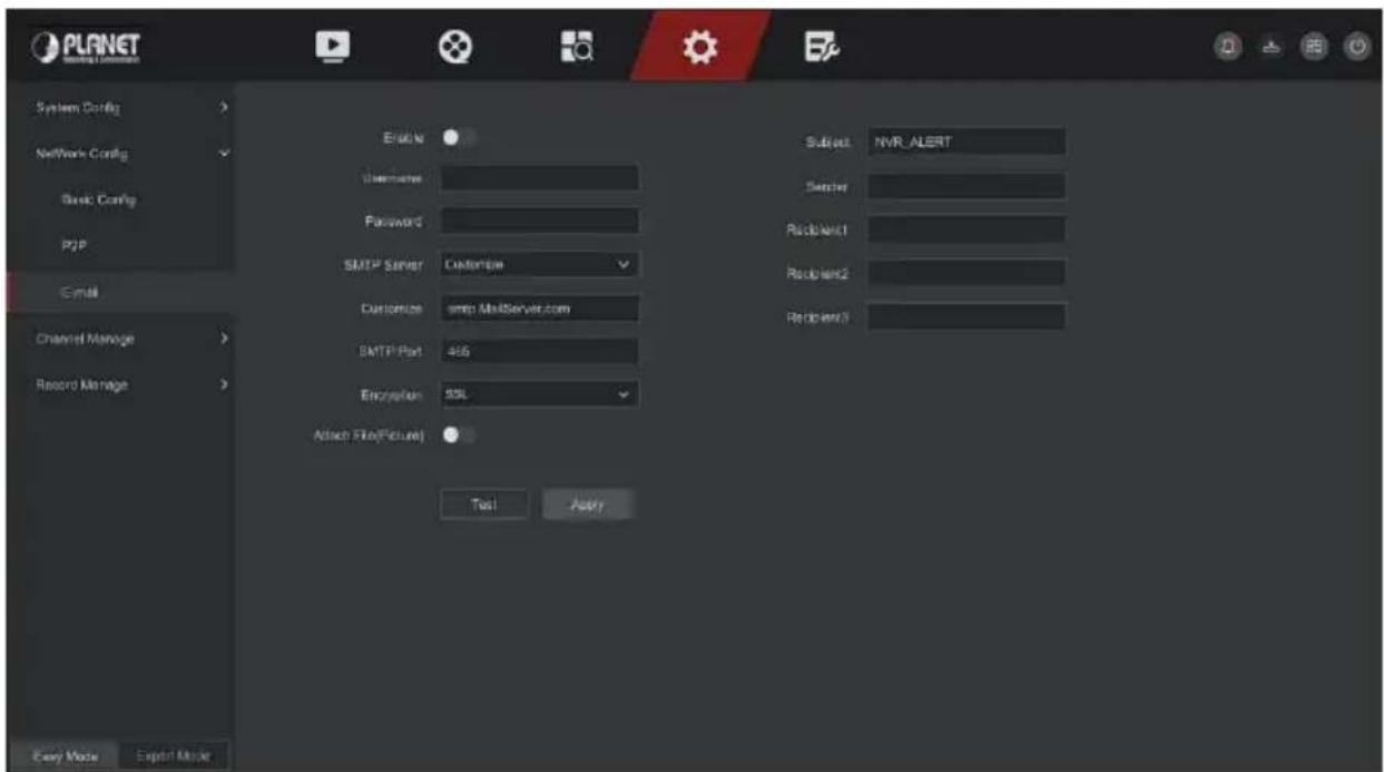
Figure 5-29
Step 2: Enable e-mail alarm notifications, configure SMTP server, SMTP port, user name, password, sender, subject, message interval, and select encryption type, attach file and other parameters.
Step 3: Click "Test" and the message "Success. Check the inbox." is displayed. Then the mail configuration is successful. If the message "E-mail can't be delivered!" is displayed, the mail configuration fails.
Step 4: After the email is sent successfully, click "Apply" to save the email configuration.
▶ Enable: Enable / disable mail sending.
- SMTP Server: Select the SMTP sever type.
SMTP Port: Please input corresponding port value here.
User Name: Please input the user name to login the sender email box.
Password: Please input the corresponding password here.
Sender: Please input sender email box here.
➢ Recipient 1/2/3: Recipient e-mail address 1/2/3.
Subject: Please input email subject here. System support English character and Arabic number, default "XNVR_ALERT".
Encryption: Select the Mailbox server encryption, including NONE, SSL, TLS, and default "SSL".
Attach File: Turn on/off the email attachment function. After the alarm is turned on, the system can send snap shots when the alarm is sent.
Test: Test email sending and receiving functions are normal. In the correct configuration, the receiving email will receive a test email. When the test fails, check the parameters or network status.
5.6.1.3 Channel Manage
■ Channel Config
■ Add Device
After adding a remote device, you can view the video screen of the remote device directly on the NVR, and perform operations such as storage and management. Different devices support different numbers of remote devices. You can add required remote devices based on actual conditions.
Prerequisites:
Before adding the device, please confirm whether the IP camera has been connected to the network where the NVR is located and set its network parameters correctly.

CAUTION
- The device may face network security problems when it is connected to the Internet. Please strengthen the protection of personal information and data. When you find that the device may have hidden network security risks, please contact us in time. It is recommended that you conduct a periodic network security assessment of the device. Our company can provide corresponding professional technical services.
- Please understand that you are responsible for properly configuring all passwords and other related product security settings, and keeping your username and password properly.
The specific operation steps are as follows:
Step 1: In the main menu, click "Config → Easy Mode → Channel Manage → Channel Config" to enter Add Camera interface, as shown in Figure 5-30.
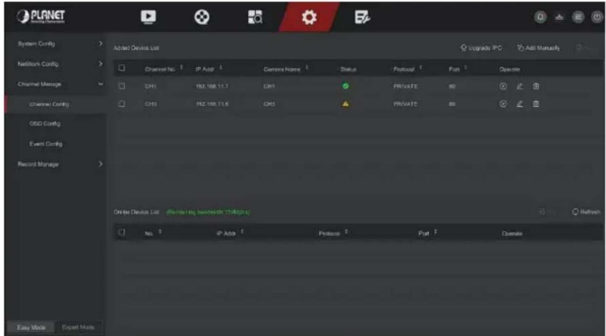
Figure 5-30
Step 2: Click "Refresh" device will search all IP cameras in the LAN and display the search results, as shown in Figure 5-31 below.
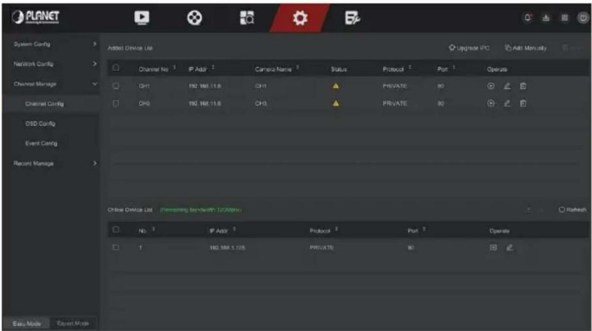
Figure 5-31
Step 3: Choose the device you want to add, click "Add", as shown in Figure 5-32 below.
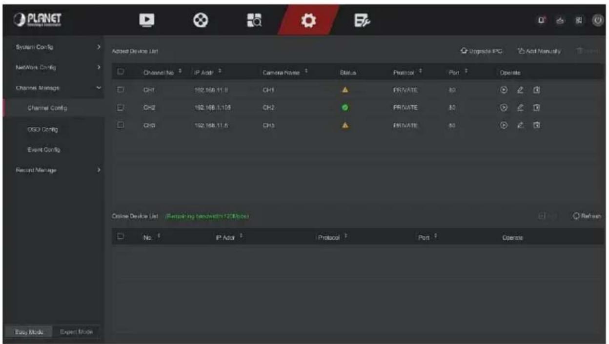
Figure 5-32
Auto Add: Click NVR to modify all camera IP and other network parameters in the LAN, and connect it to NVR.
Manual Add: Click to enter the "Channel Setup" interface. You can close the channel, switch, modify the protocol, switch the preview code stream or manually enter the device related information to add the device, as shown in Figure 5-33. Here are two methods of manually adding IP and domain name addition. When adding IPC through a domain name, only Private and ONVIF protocols are supported.
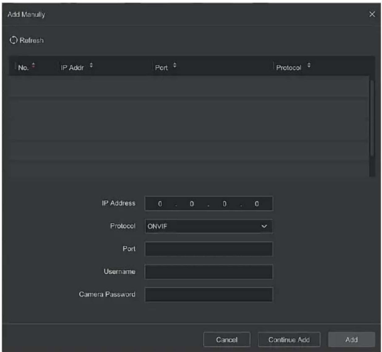
Figure 5-33
√ IP: Need to add IPC IP address.
√ Protocol: Select Add Device Protocol with Onvif, Private options.
√ Port: Access to the port used by IPC, the default is 80.
√ User Name: The login user name of IPC (if the defaulted user name is not admin, please change it to be valid user name).
√ Password: Login password of IPC (if the defaulted login password is not admin, please change it to be valid password).
Update IPC: Select one or more upgrade devices of the same type, insert the U disk storing the upgrade package of the device into the NVR, click "Upgrade", the system will find the upgrade package in the U disk and display it, select the upgrade package, click "Upgrade" to upgrade IPC in batches at the same time.
Delete: In the list of added devices, select the channel to be deleted and click the "Delete" button to delete all selected devices.
: Click and enter the channel setting interface, this function is the same as "manual add".
➢ Delete the current IPC from the device list.
Link: "✓" indicates that the connection is successful, and " 🔍" indicates that the connection fails. If the connection fails, the connection status will indicate the cause of the failure. If the password is incorrect, the user password will be incorrect.
▶: Click to view the screen of the corresponding channel.
■ OSD Config
OSD is the abbreviation of "On Screen Display", the OSD of local preview mainly includes time and channel name.
The specific operation steps are as follows:
Step 1: In the main menu, click "Config → Easy Mode → Channel Manage → OSD Config" to enter OSD config interface, as shown in Figure 5-34 below.
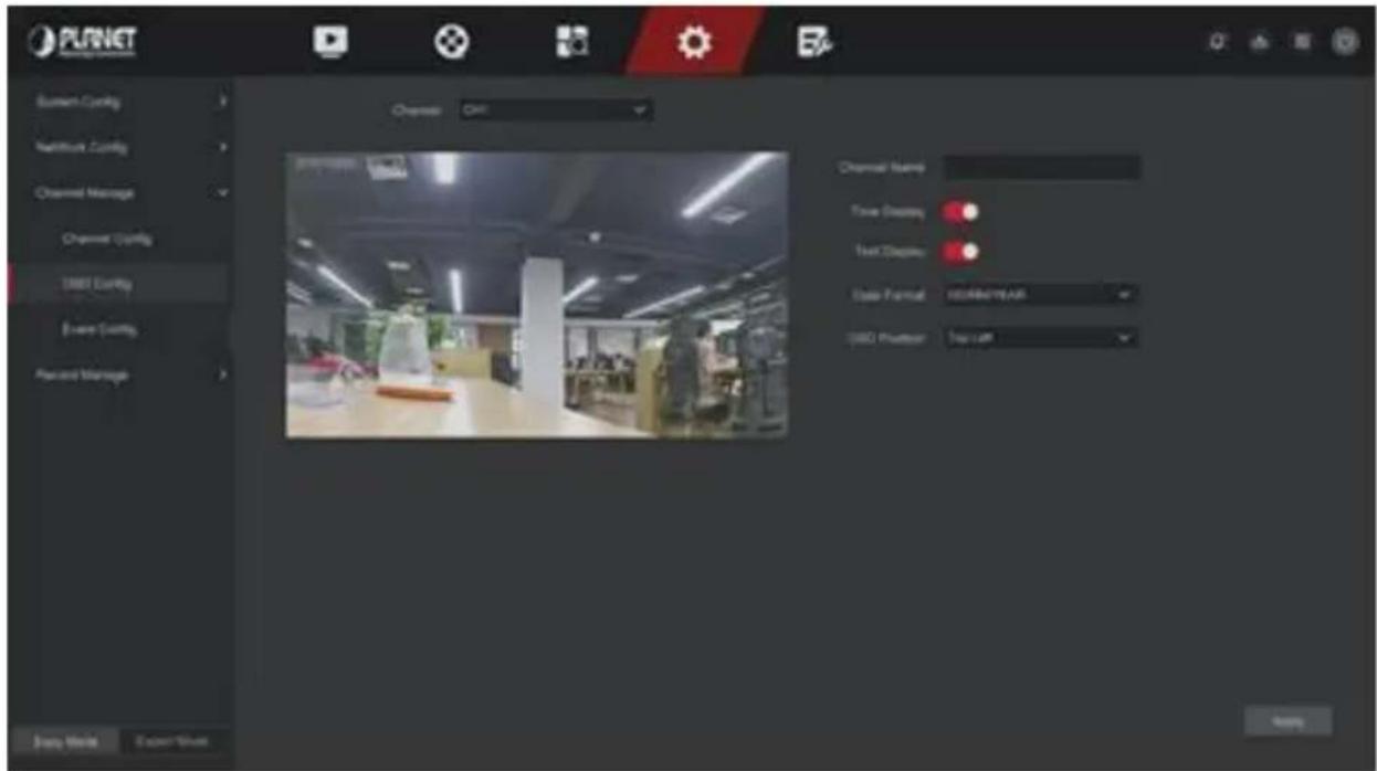
Figure 5-34
Step 2: Select the channel to set the OSD.
Step 3: Set the OSD of the channel.
Step 4: Click "Apply" to save the setting.

- OSD includes channel name, time, text, date format, OSD position and mirror.
- The current OSD function only supports the private protocol to add the device to obtain and set.
■ Event Config
■ Motion Detection / Video Tampering
Motion detection uses computer vision and image processing techniques to analyze the video images to see if there are enough changes in the images. When the moving target appears on the monitoring screen and the moving speed reaches the preset sensitivity, the system performs an alarm linkage action.
The specific operation steps are as follows:
Step 1: In the main menu, choose "Config → Easy Mode → Event Config → Motion Detection / Video Tampering" to enter Motion Detection interface, as shown in Figure 5-35 below.
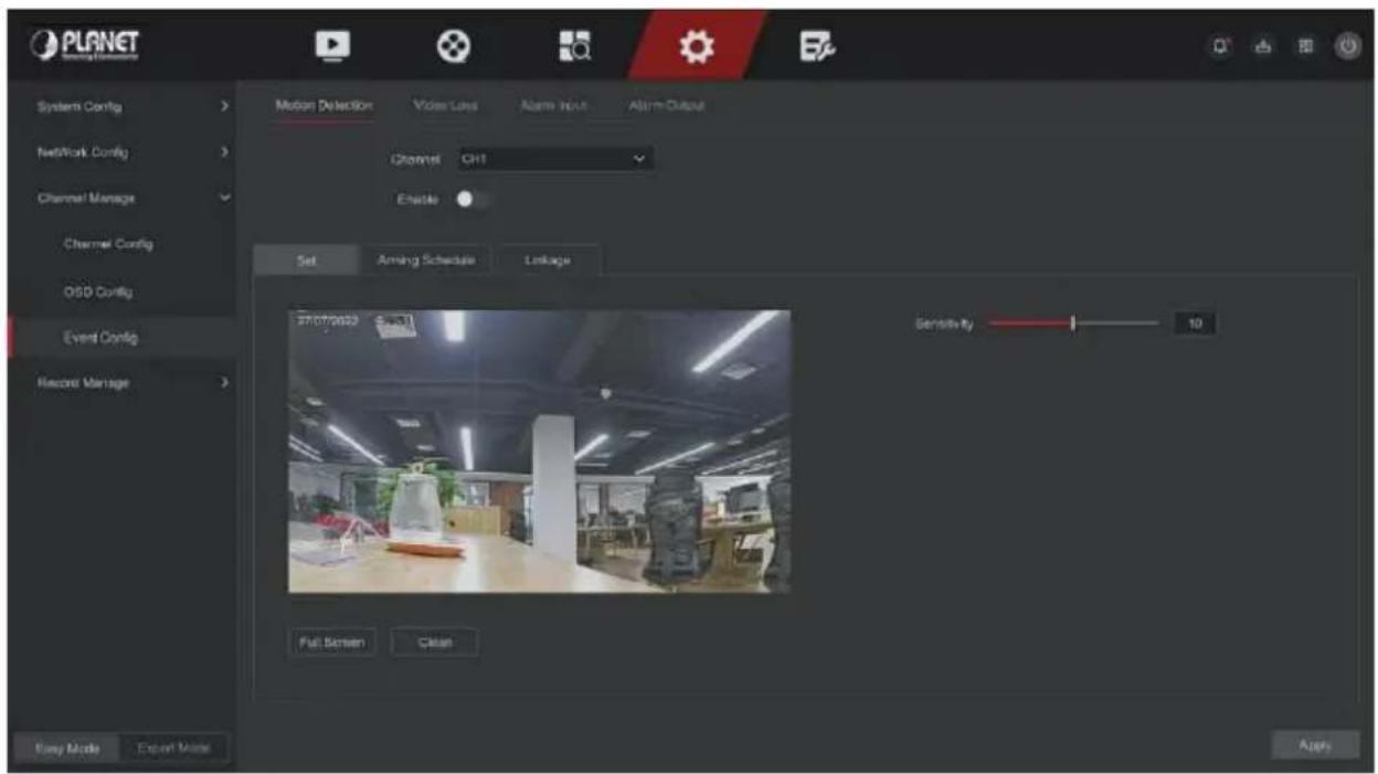
Figure 5-35
Step 2: Turn on motion detection and select a channel.
Step 3: Set area, sensitivity.
√ Use the mouse to draw the area that needs motion detection on the channel video, as shown in Figure 5-36 below.
√ Slide the sensitivity slider to select the appropriate motion detection sensitivity.
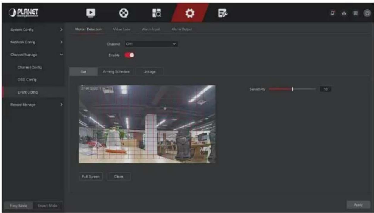
Figure 5-36
Step 4: Click "Arming Schedule" to enter Arming Schedule interface, as shown in Figure 5-37 below. Draw the arming time in the drawing area, or click "Edit Time" to set the day of the week and time period 1\~8.
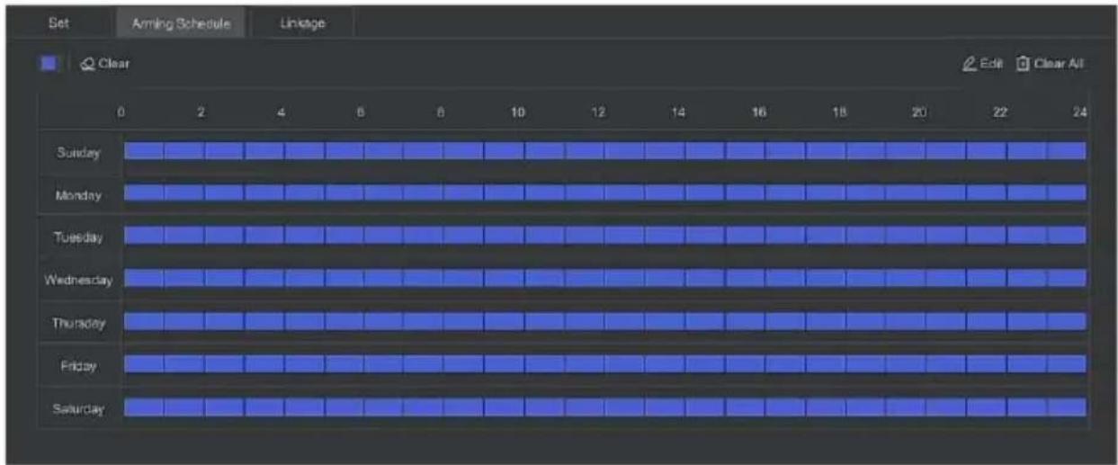
Figure 5-37
Step 5: Click "Linkage" to enter Linkage interface, Set normal linkage and alarm output as required, as shown in Figure 5-38 below.
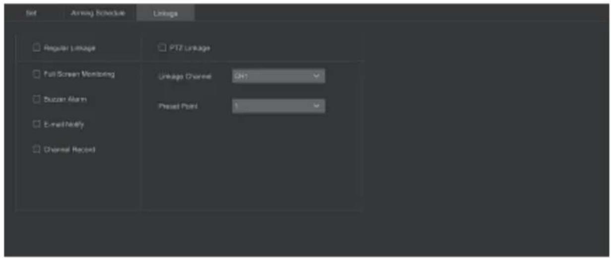
Figure 5-38
Step 6: Click "Apply" to save the setting.
 | ● If you need to set motion detection for other channels, please repeat the above steps.● After setting to enable email notification for motion detection, click " Config → Network Config → E-mail " to enter E-mail setting interface to set up the email. When the system sends a linkage alarm within the set time period, the recipient receives the alarm email.● After enabling email notification, after setting the specific week and time period, only when the alarm is triggered within the set time period, the NVR can send an email to the set mailbox to notify the user.● If the other channels have the same motion detection settings as that channel, click "Copy", select another channel, and copy the settings of this channel to other channels. |
➢ Channel: Select to set the channel.
Enable: Check "○" to turn on / off motion detection alarm.
Set Area: Select all areas by default, click to enter the area setting interface, set the range of the dynamic detection area, press and hold the left mouse button to select the alarm area. After selection, the alarm area is replaced by the red grid. Select the red grid again to cancel the alarm area setting.
Sensitivity: According to the need, can be set 0-10 eleven file sensitivity, the higher the value, the more sensitive the device.
Edit: Click to enter the Arming Schedule interface, you can manually set 8 time periods for recording every day, and copy the settings to other times through "Copy To".
➢ Buzzer Alarm: Check "☐" to turn on / off the buzzer alarm function.
E-mail Notify: Check "☐" to turn on / off when the device alerts the mail function.
Channel Record: Check "☐" to turn on / off the channel recording function.
Full Screen Monitoring: When an alarm is triggered on the preview interface, the real-time video of the device channel is displayed in full screen.
PTZ Linkage: When an alarm occurs, link the PTZ channel to the specified preset point.
■ Video Loss
When there is a channel losing video signal, the device will alarm and notify the user.
The specific operation steps are as follows:
Step 1: In the main menu, choose "Config → Easy Mode → Event Config → Video Loss" to enter Video Loss interface, as shown in Figure 5-39 below.
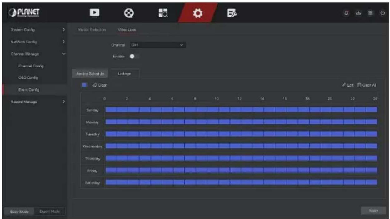
Figure 5-39
Step 2: Choose a channel, and enable the video loss.
Step 3: Set the arming time and linkage mode as needed.
Step 4: Click "Apply" to save the setting.
Screen Tips: When an alarm occurs, the device pops up an alarm screen to show a warning.
E-mail Notify: When an alarm occurs, the device will send an email as a warning.
➢ Buzzer Alarm: When an alarm occurs, the device will beep to show a warning.
PTZ Linkage: When an alarm occurs, link the PTZ channel to the specified preset point.
5.6.1.4 Record Manage
■ Record Plan
NVR supports two recording plan, drawing method and editing method.
■ Set the recording plan by drawing method
The specific operation steps are as follows:
Step 1: In the main menu, click "Config → Easy Mode → Record Manage → Record Plan" to enter record plan setup interface, as shown in Figure 5-40 below.
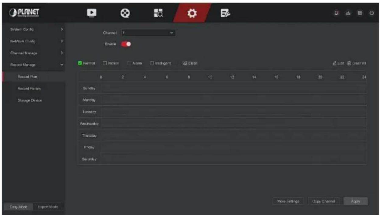
Figure 5-40
Step 2: According to the needs of recording, select channel, enable, recording type (Normal, Motion, Alarm, Intelligent), week and other options Step 3: Click the left mouse button to locate the starting point of the drawing area, drag the mouse to determine the time of the recording plan, release the left mouse button to save as a recording plan, as shown in Figure 5-41 below.
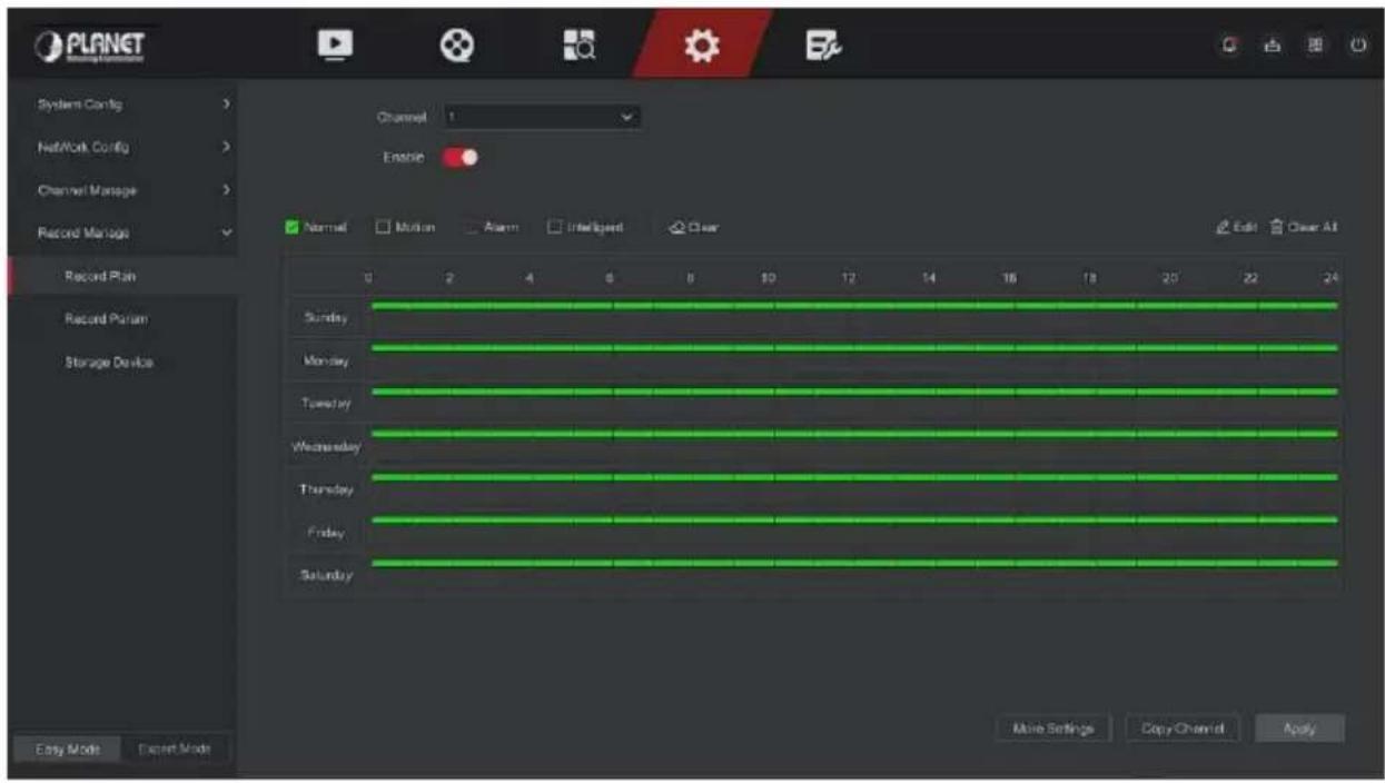
Figure 5-41
Step 4: Repeat Step 3 to set up a complete recording plan.
Step 5: After the recording plan is set, the channel presents the type (color) of the recording plan, as shown in Figure 5-42 below.
Figure 5-42

- There are 8 time periods available for each day, and the device will start the corresponding type of recording within the set time range.
● The smallest unit of the drawing area is 1 hour. - Press and hold the left mouse button in the drawing area, then drag the box to select, you can edit the time period of each day of the week synchronously.
■ Set the recording plan by editing method The specific operation steps are as follows:
Step 1: In the main menu, click "Config → Easy Mode → Record Manage → Record Plan" to enter record plan setup interface.
Step 2: Click "Edit" to enter "Modify Schedule" setting interface, as shown in Figure 5-43 below.
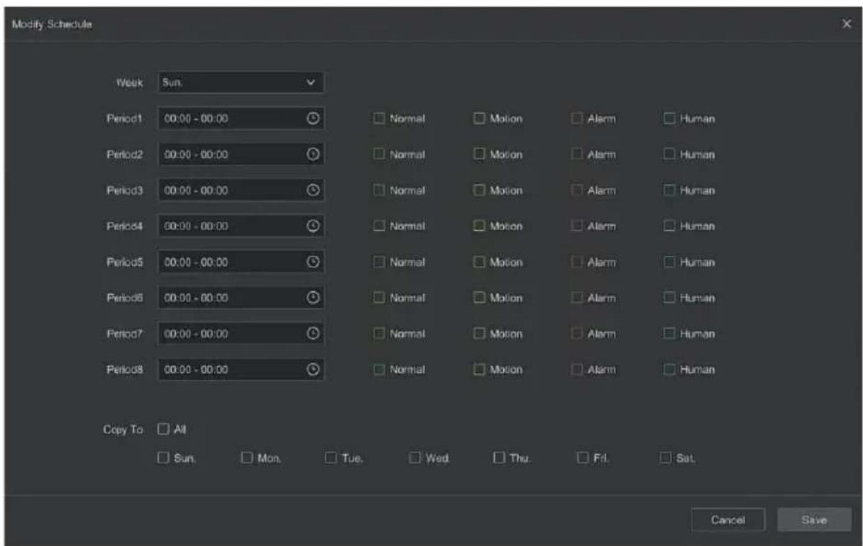
Figure 5-43
Step 3: Select the recording type of each time period. There are eight time periods for setting each day. Select the corresponding week in "Save" to apply to the corresponding week.
Step 4: Click "Save" to complete the setting, the system will return to "Record" interface.
Record Type: Select check the box to select corresponding record type. There are Normal, Motion, Alarm, and Intelligent.
Week day: Select the week number. If you select "All", it means to the entire week, or you can select "" in front of the number of days to set individual days.
More Settings: You can set the prerecord time(s) and post-record(s), as shown in Figure 5-44 below.
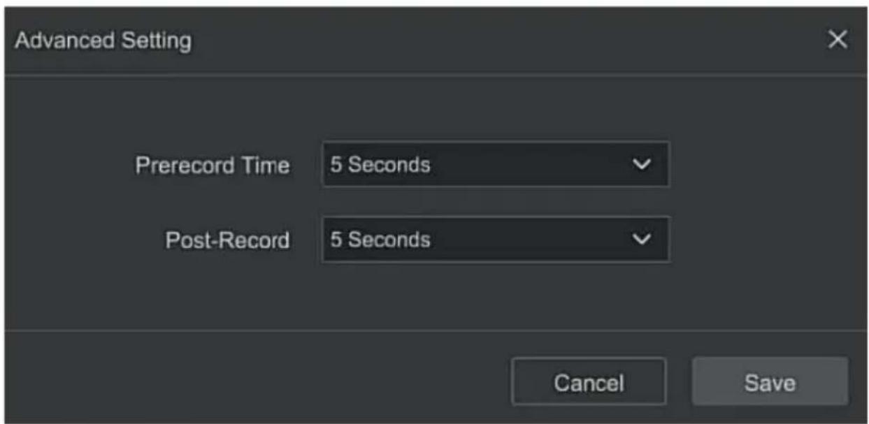
Figure 5-44
Copy Channel: After complete the setup, you can click "Copy Channel" button to copy current setup to other channel(s), as shown in Figure 5-45.
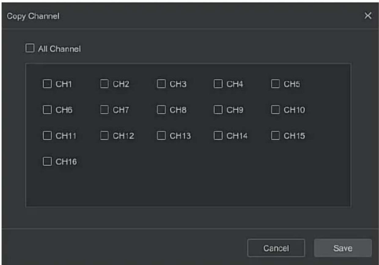
Figure 5-45
■ Record Param
Record Param interface is used for recording parameter configuration.
The specific operation steps are as follows:
Step 1: In the main menu, click "Config → Record Manage → Record Param" to enter record param setup interface, as shown in Figure 5-46 below.
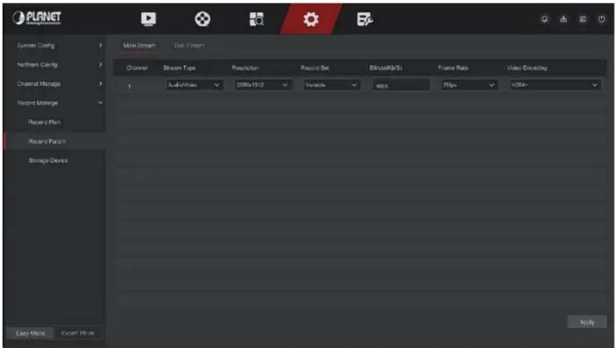
Figure 5-46
Step 2: Set recording parameters, please refer to Table 5-5 for specific parameter descriptions.
| Name | Details | Setting |
| Channel | Select the channel to set recording parameters | |
| Record Set | There are two types of video compression parameters: Main Stream (timing) and Main Stream (Event). Main Stream (timing): Encoding parameters for ordinary recording.Main Stream (Event): encoding parameters for events such as motion detection, alarm input, and smart detection. | NOTE:The event parameters cannot be set and are consistent with the timing parameters. |
| Resolution | Resolution refers to the number of pixels contained in a unit length. | Select through the drop-down box. NOTE: The encoding resolution is related to the IP device. |
| Stream Type | The stream type is Video & Audio (composite stream), and the recording information includes video and audio. | Select through the drop-down box. |
| Frame Rate | Video frame rate refers to the number of video frames per second. | Adjust via slider. |
| Bitrate(Kb/S) | Set the code stream value to change the quality of the image quality, the larger the code stream, the better the image quality. | Modify it directly in the input box. |
| Video Encoding | H264,H265,H264+,H265+ | Select through the drop-down box. NOTE: The encoding type is related to the IP device. |
Table 5-5
Step 3: Click "Apply" to save the setting.
■ Storage Device
The storage device is used to format the hard disk and view the hard disk's applicable status and capacity.
■ Disk Management
Formatting the hard drive
Prerequisites:
The user has installed the hard disk correctly. For details of the hard disk installation procedure, please refer to the "NVR Quick Start Guide".
The specific operation steps are as follows:
Step 1: In the main menu, click "Config → Easy Mode → Record Manage → Storage Device" to enter storage device interface, as shown in Figure 5-47 below.
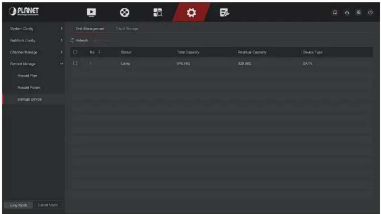
Figure 5-47
Step 2: Select the hard drive that needs to be formatted, click "Format", as shown in Figure 5-48 below.
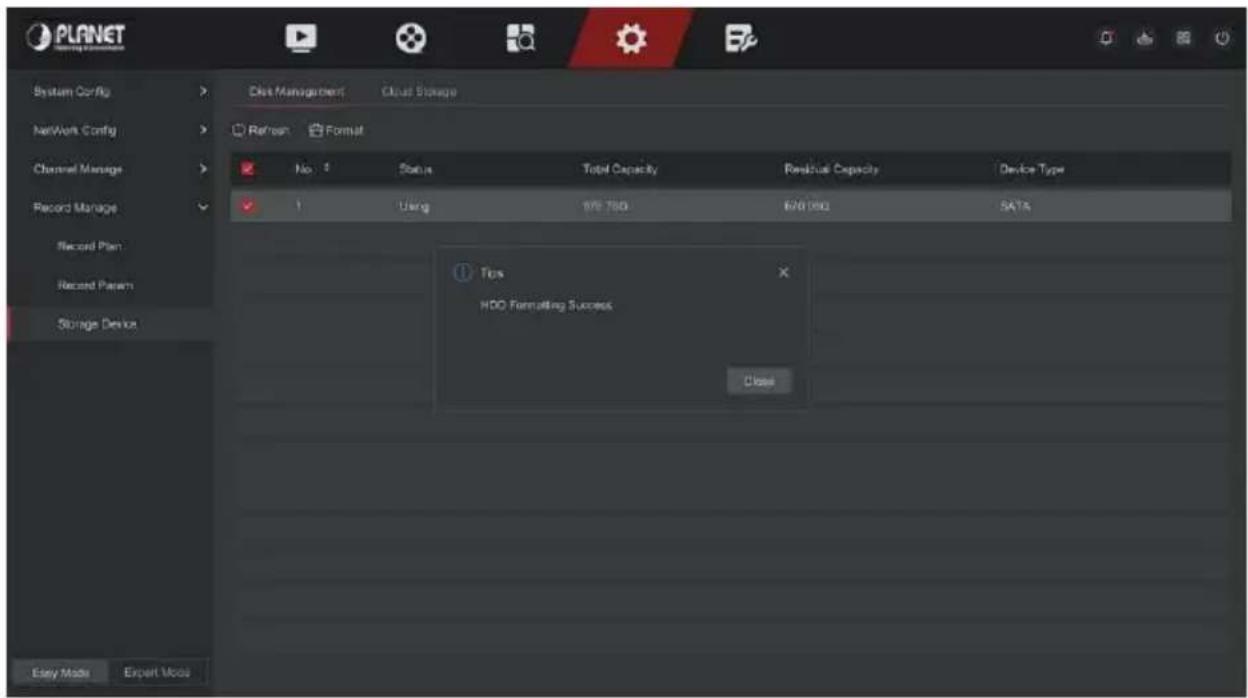
Figure 5-48
Step 3: Wait for the formatting progress bar to finish, click "Close", the NVR will restart and complete the format. The status of the hard disk is "Using" at this time.
No.: The number of HDD that connect the system.
State: Detect the current working status of HDD, you could use only that displays "In use"; after formatting is completed, you need to restart NVR, the status displays "In use".
Total Capacity: The total available HDD capacity, the single HDD capacity can't exceed the maximum capacity: 8TB.
➢ Residual Capacity: Display the residual capacity of the current HDD;
Device Type: SATA.
Refresh: Click update disk list information.

- "No Disk" indicates that the device is not connected or the hard disk is not detected.
- The hard disk must be formatted first when the hard disk is connected to the NVR for the first time or when "Not formatted" is displayed.
- The device does not need to format the hard disk when the hard disk status shows "In Use".
● After formatting the hard disk, restart the NVR to takes effect. The smallest unit of the drawing area is 1 hour.
■ Cloud Storage
Set cloud storage. When the device triggers an alarm, it can store the captured alarm image of the device on the cloud server.
Prerequisites:
1) You need to have a Google Cloud Storage account.
2) Using this function, the device must be connected to an external network; otherwise it will not work properly.
The specific operation steps are as follows:
Step 1: On the main menu page, select " Config → Easy Mode →
Record Manage → Storage Device → Cloud Storage " to enter the cloud storage setting interface, as shown in Figure 5-49.
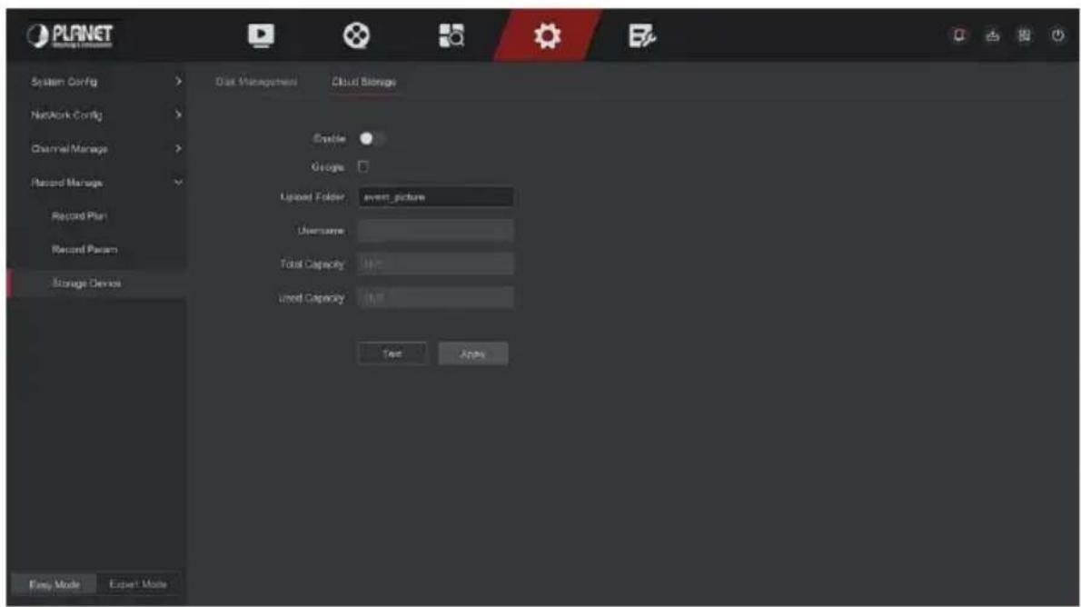
Figure 5-49
Step 2: Select "Enable → Google" to obtain the "Authorization Code". Follow the prompts to log in to the website on the computer and enter the "Authorization Code" to bind the Google server cloud service.
Step 3: Click "Apply".
Step 4: Click "Test" to test whether the XVR can successfully upload files to the cloud server. After the binding is successful, the cloud storage interface displays the "Google" username, total capacity, and used space.
Enable: Turn on/off the device cloud storage function.
Google: Select a cloud storage type and enter the binding interface.
Upload Folder: Set the upload cloud space folder name.
Username: Displays the user name of the Google.
Total Capacity: After the cloud storage binding is successful, the total capacity of the cloud space is displayed.
➢ Used Capacity: Cloud storage binding is successful; the display of cloud space has been used capacity.
Test: After binding, click "Test" to confirm whether the binding is successful. If the test fails, check whether the device is properly connected to the network and the cloud storage configuration.
5.6.2 Expert Mode
5.6.2.1 System Config
■ Common Config
In Common Config interface, you can view and set the NVR language, time zone, date format, system time, resolution, device name, screen saver time, mouse movement speed, enable or disable daylight saving time, boot wizard, operation password function.
The specific operation steps are as follows:
Step 1: In the main menu, click "Config → Expert Mode → System Config → Common Config" to enter common config interface, as shown in Figure 5-50 below.
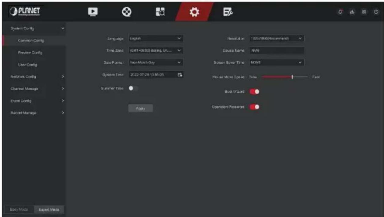
Figure 5-50
Step 2: Set the language, time zone, date format, daylight saving time and other information of the device as required.
Language: Set the default language of the system, currently supports Simplified Chinese, Traditional Chinese, English, Polish, Czech, Russian, Thai, Hebrew, Bulgarian, Arabic, German, French, Portuguese, Turkish, Spanish, Italian, Hungarian, Roman, Korean, Dutch, Greek, Vietnamese, Japanese, Bengali, Ukrainian and Persian, the default is English.
Time Zone: Select the time zone of the device from the drop-down box. For example: Beijing is GMT+8:00.
Date Format: Select the date display format, including "Day Month Year", "Month Day Year" and "Year Month Day".
System Time: Click the time display bar to pop up the calendar and time bar, select the corresponding date and time.
➢ Summer Time: Open the daylight saving time function, set the relevant parameters, such as Type, Date, Start Time, End Time and so on.
Resolution: Displays the resolution of the current device output, the selectable values are 1024×768, 1280×720, 1280×1024, 1920×1080, 3840×2160 NVR HD high-definition interface supports maximum 4K resolution output.
Device Name: Fill in the name of the device according to actual needs, the default is NVR.
Screen Saver Time: The default is 10 minutes, can be set range: 1 Minute, 2 Minutes, 5 Minutes, 10 Minutes, 20 Minutes, 30 Minutes, 60 Minutes and Never, where "Never" for the permanent standby.
Mouse Pointer Speed: Set the mouse movement speed.
Boot Wizard: It is enabled by default, and the "Boot Wizard" is turned on, and the "Boot Wizard" interface is directly entered each time the machine is turned on.
Operation Password: It is enabled by default and can enter the system without a password after it is disabled.
Step 3: Click "Apply" to save the setting.
■ Preview Config
Carousel
The device supports the carousel function. After setting, the system will play video frames in turn according to the split screen. After each group of pictures is displayed for a certain time, it will automatically jump to the next group of pictures, as shown in Figure 5-51:
Step 1: Click "Config → Expert Mode → System Config → Preview Config → Carousel" on the main interface to enter the cruise setting interface, as shown in Figure 5-51 below.
Step 2: Select the polling split screen mode, polling interval, and polling channel.
Step 3: Click "Save".
Step 4: In the preview interface, click the cruise button in the lower right corner of the interface or click the cruise button in the shortcut menu to start the cruise.
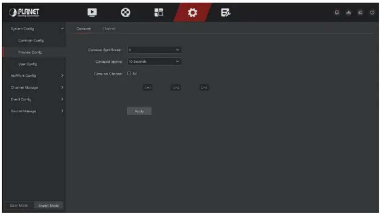
Figure 5-51
- User Config

- The factory default administrator user name is admin and the password is admin.
- Administrators can add and delete users and configure user parameters.
- The user level has two levels, the Operator and the General user.

CAUTION
- In order to improve the security of the product's network use, please update the product password regularly. It is recommended to update and maintain it every 3 months. If you have high security requirements for the product environment, it is recommended to update the password monthly or weekly.
- It is recommended that administrators effectively manage device accounts and user permissions, delete irrelevant users and permissions, and close unnecessary network ports.
- Administrators should configure user rights appropriately, and recommend using custom users for management in daily maintenance.
■ Add User
The specific operation steps are as follows:
Step 1: In the main menu, choose "Config → Expert Mode → System Config → User Config" to enter User interface, as shown in Figure 5-52.
User list: Displays all current users of the device; the administrator can only change its password, not its permissions.
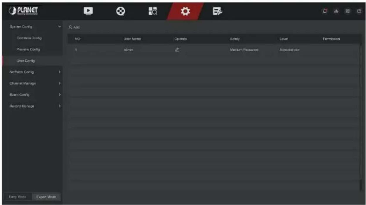
Figure 5-52
Step 2: Click "Add" to enter the permission confirmation interface, first confirm the password, as shown in Figure 5-53 below.
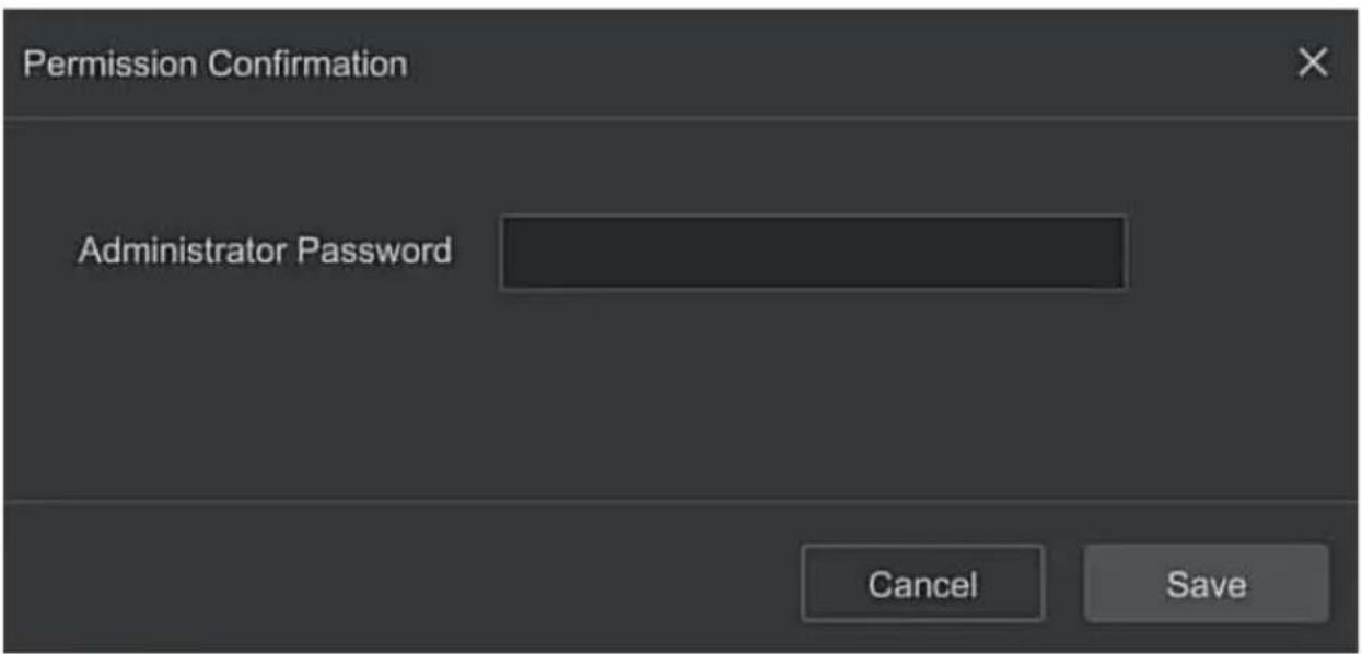
Figure 5-53
Step 3: Enter the administrator password, click "Save", after the permission is confirmed, you can enter the add user interface to add users, as shown in Figure 5-54 below.
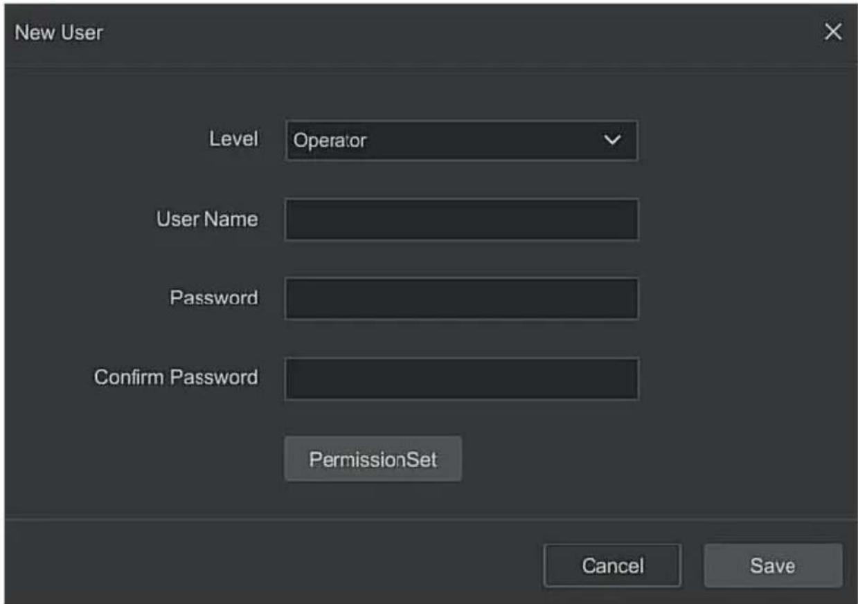
Figure 5-54
Step 4: Choose a level, enter the new user information (user name, password, confirm password), select the level, click "Save".
Step 5: Setting permissions. Click the "PermissionSet" button to enter the permission setting interface, and set the user permission.
▶ Authority Description
Authority are divided into local configuration, remote configuration, channel configuration, administrator users can enable / disable corresponding permissions as needed.
- Local Config
√ Local Param Setup: set parameters, restore default parameters, import / export parameters.
√ Local Channel Setup: Add, delete, modify, import and export configuration files for the IP channel.
√ Local User: Check the User Management interface.
√ Local Disk: View and set recording plans, format storage devices.
√ Local Log: View system logs, system information.
√ Local Update: Upgrade the device locally.
√ Local Restore Default: you could restore default parameters.
√ Local Shutdown Reboot: You can shutdown and reboot the device.
- Remote Config
√ Remote Param Setup: Set parameters remotely, restore default parameters, import / export parameters.
√ Remote Channel Setup: Add, delete, modify IP channels remotely.
√ Remote User: View the User interface remotely.
√ Remote Disk: View and set recording plans, format storage devices remotely.
√ Remote Log: View system logs remotely.
√ Remote Update: Upgrade the device on the web.
√ Remote Restore Default: You could restore default parameters remotely.
√ Remote Shutdown Reboot: You can shutdown and reboot the device remotely.
- Channel Config
√ Local Preview: Preview live video of each channel locally, this permission is detailed for each channel.
√ Remote Preview: Preview live video of each channel remotely, this permission is detailed for each channel.
√ Local Record: Set the recording plan of each channel locally, this permission is detailed for each channel.
√ Remote Record: Set the recording plan of each channel remotely, this permission is detailed for each channel.
√ Local Playback: Playback video files on NVR locally, this permission is detailed for each channel.
√ Remote Playback: Remote playback, download video files on NVR, this permission is detailed for each channel.
√ Local PTZ: this permission is detailed for each channel.
√ Remote PTZ: this permission is detailed for each channel.
√ Local Backup: Backup video files on NVR locally, this permission is detailed for each channel. Channels with local backup authority must have local playback authority.
√ Remote Backup: remote backup the video files from NVR, this permission is detailed for each channel. A channel with remote backup authority must have remote playback authority.

- Only the admin administrator has the right to "restore default parameters".
- Channel permissions support individual permission settings for a channel.
Step 6: Click "Save" to save the set permissions and return to the user management interface, as shown in Figure 5-55 below.
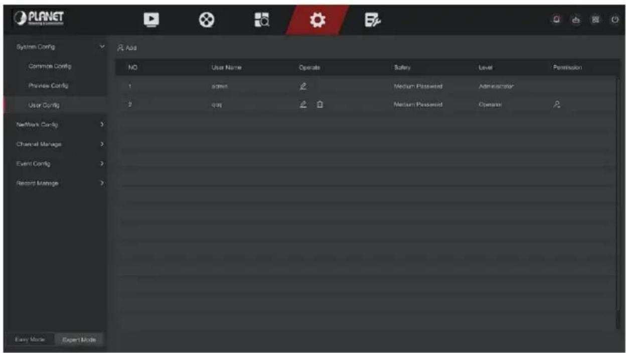
Figure 5-55
5.6.2.2 Network Config
■ Basic Config
TCP/IP
Set the IP address, DNS server and other information of the NVR device to ensure that it can communicate with other devices in the network.

- If the device is used for network monitoring, the network must be set up for normal use.
● Factory default IP: 192.168.0.20
The specific operation steps are as follows:
Step 1: In the main menu, click "Config → Expert Mode → Network Config → Basic Config → TCP/IP" to enter TCP/IP to set the interface, as shown in Figure 5-56 below.
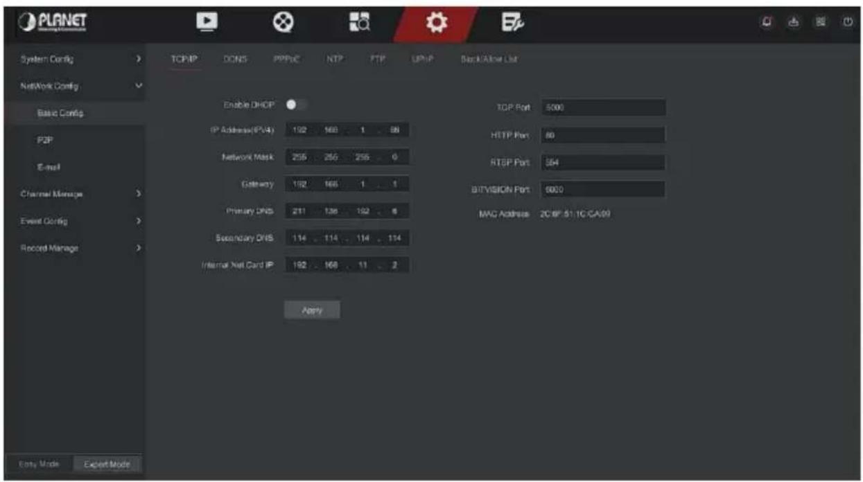
Figure 5-56
Step 2: Configure IP Address, Network Mask, Gateway, Primary DNS and other related network parameters.
Step 3: Click "Apply" to save the setting.
IP Address: Enter the IP address of NVR.
Enable DHCP: Enable / disable DHCP (Dynamic Host Configuration Protocol) function. "IP Address", "Network Mask", and "Gateway" can't be set when DHCP is enabled.
Network Mask: According to the actual situation set.
Gateway: According to the actual situation set, with the IP address in the same network segment.
Primary DNS: This is the DNS server IP address, which is usually provided by the local access point service provider (ISP). Enter the IP address of your domain name server here.
Secondary DNS: Start secondary DNS when the primary one does not work.
MAC Address: Displays the physical address of the NVR.
TCP Port: Default value is 5000, according to the actual needs of users to set the port.
HTTP Port: Default value is 80, according to the actual needs of users to set the port.
RTSP Port: Default value is 554, according to the actual needs of users to set the port.
Bitvision Port: Default value is 6000, according to the actual needs of users to set the port.
Internal Net Card IP: Set the intranet IP address for connecting the POE device of the device.

- The IP address and the default gateway must be in the same network segment.
- If NVR enabled DHCP is in effect and you turn off DHCP, you cannot display the original IP information. You need to reset the IP address and other parameters.
- Only PoE-capable devices have an internal network card function. Please refer to the actual product.
- The internal network adapter IP and NVR IP address cannot be on the same network segment.
■ DDNS
After the DDNS (Dynamic Domain Name Server) parameter is set, when the
IP address of the NVR device changes frequently, the system can dynamically update the relationship between the domain name and the IP address on the DNS server. You can use the domain name to access the NVR directly without recording the constantly changing IP address.
Prerequisites:
Before configuring DDNS, make sure that the device supports the type of domain name resolution server, and log in to the DDNS service provider's website to register user name, password, domain name, and other information on the WAN PC.
The specific operation steps are as follows:
Step 1: On the menu page, select "Config → Expert Mode → Network Config → Basic Config → DDNS" to enter the DDNS interface, as shown in Figure 5-57.
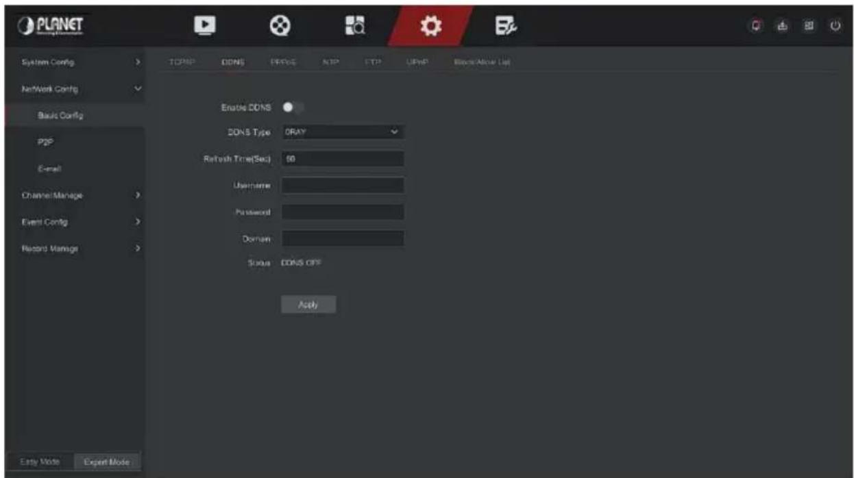
Figure 5-57
Step 2: Enable DDNS, select the DDNS type, and enter the refresh time (Sec), username, and password.
Step 3: Click "Apply" to save the DDNS setting.
Step 4: Enter the domain name in the PC web browser and press "Enter". If you can display the web interface of the device, the configuration is successful. If it is not displayed, the configuration fails.
Enable DDNS: Enabling DDNS domain resolving function.
DDNS Type: Select the DDNS type by dynamic domain name resolution server. (At present, the device supports multiple DDNS, including ORAY, NO-IP, DYN, CHANGEIP, A-PRESS, MYQSEE, SKDDNS, SMART-EYES, ZEBEYE, DYNAMIC_Planet, EASY_Planet. These multiple DDNSs can coexist at the same time, and the user can select and set them as needed).
➢ Refresh Time (Sec): Do not register frequently. The interval between two registrations shall be more than 60 seconds. Too many registration requests may result in server attack.
User Name: The account registered in the DNS service provider.
Password: The password to the account registered in the DNS service provider.
Domain: The domain name registered in the DNS service provider.

- After setting up DDNS, ensure that the NVR is connected to the WAN to access the device through the DDNS domain name.
■ PPPoE
PPPoE(Point-to-Point Protocol over Ethernet) is one of the ways in which XVR devices access the network. After obtaining the PPPoE user name and password provided by the Internet Service Provider, you can establish a network connection through PPPoE dialup. After the connection is successful, the XVR device automatically obtains a dynamic IP address of the WAN.
The specific operation steps are as follows:
Step 1: In the main menu, click "Config → Expert Mode → Network Config → Basic Config → PPPOE" to enter PPPOE to set the interface, as shown in Figure 5-58 below.
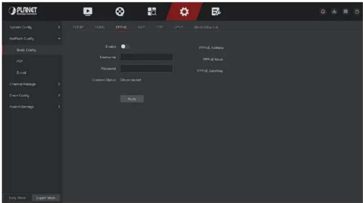
Figure 5-58
Step 2: Select "Enable", input the user name and password of the PPPoE.
Step 3: Click "Apply" to save the configuration.
Enable: Turn on/off the device PPPoE function.
User Name: The PPPoE user name provided by the ISP (Internet Service Provider).
➢ Password: The password corresponding to the user name.
| Note | ● After setting successfully, you could check the status of the PPPOE from" Config → Expert Mode → Network Config → Basic Config → PPPOE ". ● After completing the setting, the device will automatically dial after restarting. After successful dialing, the network information can be displayed in the network status, and users can access the device through the IP address. ● After the configuration is complete, the IP address of the TCP/IP interface cannot be modified. |
NTP
After enable NTP (Network Time Protocol), the system can periodically adjust the device time through the NTP server to ensure the accuracy of the device system time.
The specific operation steps are as follows:
Step 1: In the main menu, click "Config → Expert Mode → Network Config → Basic Config → NTP" to enter NTP to set the interface, as shown in
Figure 5-59 below.
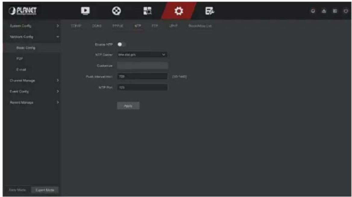
Figure 5-59
Step 2: Choose "Enable NTP" to set NTP related parameters.
NTP Sever: Select the domain name of the server where the NTP service is installed.
Customize: When the NTP server selects "Custom", enter the NTP server domain name manually.
➢ Push interval (Min): The interval of NTP time correction, the default is 720 minutes, and the settable range is 30-1440 minutes
NTP Port: Select the port corresponding to the NTP server.
Step 3: Click "Apply" to save the setting.
FTP
With FTP (File Transfer Protocol) server, you can store alarm pictures on the FTP server.
Prerequisites:
You need to purchase or download the FTP service tool and install the software on your PC.

- To create an FTP user, you must set FTP folder write permission. Otherwise, the picture will not be uploaded successfully.
The specific operation steps are as follows:
Step 1: On the main menu page, click "Config → Expert Mode → Network Config → Basic Config → FTP" to enter the FTP interface, as shown in Figure 5-60.
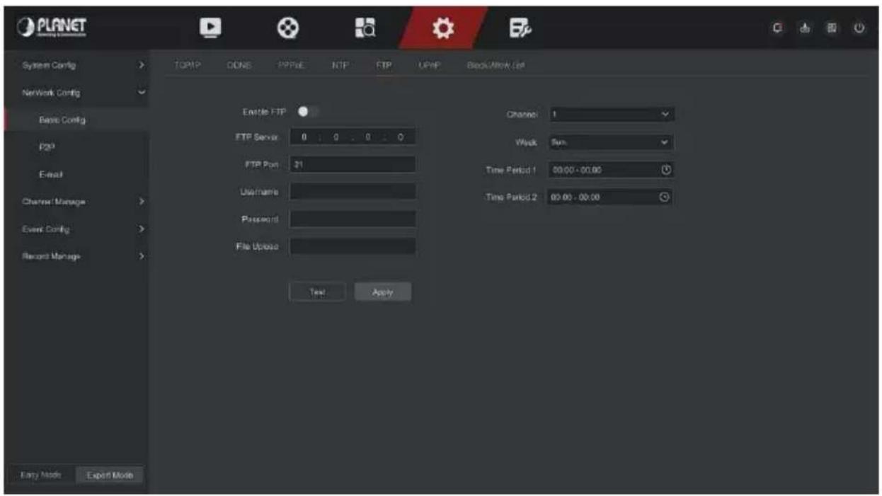
Figure 5-60.
Step 2: Select "Enable FTP" and enter parameters such as the FTP Server, FTP Port, User Name, Password, and the File Upload path.
Step 3: Click "Apply" to save the configuration.
Step 4: Click "Test" to determine whether the network connection and FTP configuration are correct.

Note
- If the test fails, recheck the network or FTP configuration.
Enable FTP: Turn on / off the device FTP function.
FTP Server: Host IP address of the FTP server.
FTP Port: The default FTP port is 21, if your FTP server is different; you need to use the same port name with your FT server.
User Name: Please input the user name to login the FTP server.
➢ Password: Please input the corresponding password here.
File Upload: Create folders according to the rules in the FTP account directory.
√ When the remote directory is empty, the system will save the uploaded image in the root directory of the FTP server.
√ Enter the name of the remote directory, the system will create a folder with the corresponding name under the FTP root directory, and save the uploaded pictures in this folder.
Channel: Select the channel to upload the capture file.
Week: Select the time to upload the FTP file according to the week. You can set two time periods each week.
Time period 1&2: Set the time period for uploading FTP files in one day.
Test: Click "Test", test NVR can successfully upload files to the FTP server.
■ UPnP
After the mapping between the internal network and the external network is established through the UPnP protocol, the external network user can use the external network IP address to directly access the NVR device on the intranet.
Prerequisites:
1) Log in to the router and set the IP address of the router's WAN port to access the external network.
2) Make sure that the router is a first-level router (or virtual first-level router) and turn on the UPnP function.
3) Connect the device to the LAN port of the router and access the private network.
4) In the main menu, select "Config → Expert Mode → Network Config → Basic Config → TCP/IP ", set "IP Address" as the router's private IP (for example: 192.168.1.101) or select "DHCP" to obtain the IP address automatically.
The specific operation steps are as follows:
Step 1: On the main menu page, click "Config → Expert Mode → Network Config → Basic Config → UPnP" to enter the UPnP interface, as shown in Figure 5-61.
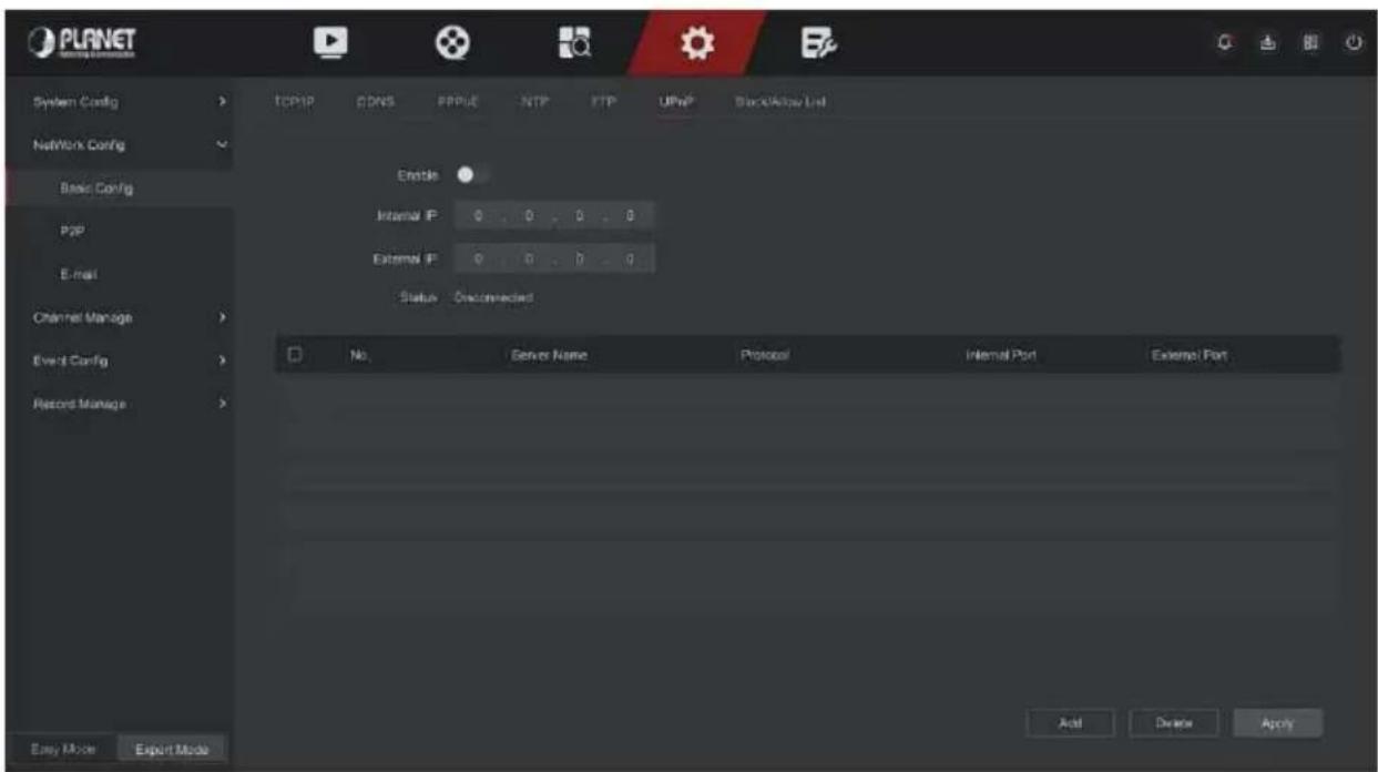
Figure 5-61
Step 2: Enable the UPnP function and configure related parameters such as Internal IP, External IP, and port mapping information of the UPnP route.
Step 3: Click "Apply" to save the configuration.
Enable: Turn on/off the device UPnP function.
Status: Displays the mapping status of UPnP.
Internal IP: Enter the router's LAN port address. After the mapping is successful, the IP address will be automatically obtained without setting.
External IP: Enter the router's WAN port address. After the mapping is successful, the IP address will be automatically obtained without setting.
Port Mapping Table: This corresponds to the UPnP mapping table information on the router.
Server Name: The web server name.
▶ Protocol: The type of agreement.
Internal Port: The port that the local machine needs to map.
External Port: The port mapped on the router.
Add: Click "Add" to increase the mapping, enter the service name, internal port, and external port.
Server Name: Enter the service name and define it yourself.
Internal Port: You need to enter the corresponding HTTP port, RTSP port, TCP port.
External Port: Can be self-defined, and the internal port can be the same, but can't and NVR other ports repeat.
Delete: Select the mapping information in the port mapping table and delete the mapping relationship.

Note
- When setting the external port of the router mapping port, try to use the port between 1024 and 65535. Avoid using the well-known port 1\~255 and the system port 256\~1023 to avoid conflict.
- When deploying multiple devices in the same LAN, plan the port mapping to avoid mapping multiple devices to the same external port.
- When performing port mapping, ensure that the mapped port is not occupied or restricted.
- TCP internal and external ports must be consistent and cannot be modified.
■ Block/Allow List
The Block/Allow List restricts the PC to log in to the NVR web client by filtering the IP address or MAC address. There are two types: black list and white list.
▶ Blocklist:
- NVR cannot connect to IPC's IP address or MAC address in the blocklist.
- The computer with the IP or MAC address in the blocklist will not be able to log in to the NVR web page.
Allowlist:
- The device can only connect to the IPC in white list.
- Only IPCs in the whitelist can access the NVR.
Add Blocklist / Allowlist operation steps are shown as below:
Step 1: In the main menu, choose "Config → Expert Mode → Network Config → Basic Config → Block/Allow List" to enter Block/Allow List setting
interface, as shown in Figure 5-62 below.
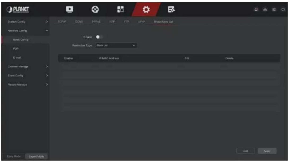
Figure 5-62
Step 2: Choose "Restriction Type", such as "Blocklist".
Step 3: Click "Add", choose IP address (or MAC address), input IP address.
Step 4: Click "Apply", the IP address or MAC address will be added to the Blocklist of the device.

CAUTION
● The device supports adding up to 128 allowlists and 128 blocklists.
- Double-click a list in the filter list to enter the add interface, you can modify the IP address or MAC address.
- When you add the Blocklist / Allowlist, the letters in MAC address can be uppercase or lowercase, and are separated by ":", such as "00:bb:f2:00:15".
- When the IP Restriction Type is Blocklist / Allowlist, only one list is in effect at a time.
P2P
P2P is a private network penetration technology. It does not need to apply for a dynamic domain name, perform port mapping, or deploy a transit server. You can directly scan the QR code to download a mobile client.
After registering an account, you can add and manage multiple IPC, NVR, XVR devices simultaneously on the mobile client.
You can add devices in the following two ways to manage multiple devices.
1) Scan the QR code for the mobile phone system, download the App and register the account. For details, see the App User Manual on the website.
2) Log on to the P2P platform, register an account, and add the device via the serial number.

- With this function, the device must be connected to an external network; otherwise it will not work properly.
The specific operation steps are as follows:
Step 1: On the main menu page, click "Config → Expert Mode → Network Config → P2P" to enter the P2P interface, as shown in Figure 5-63.
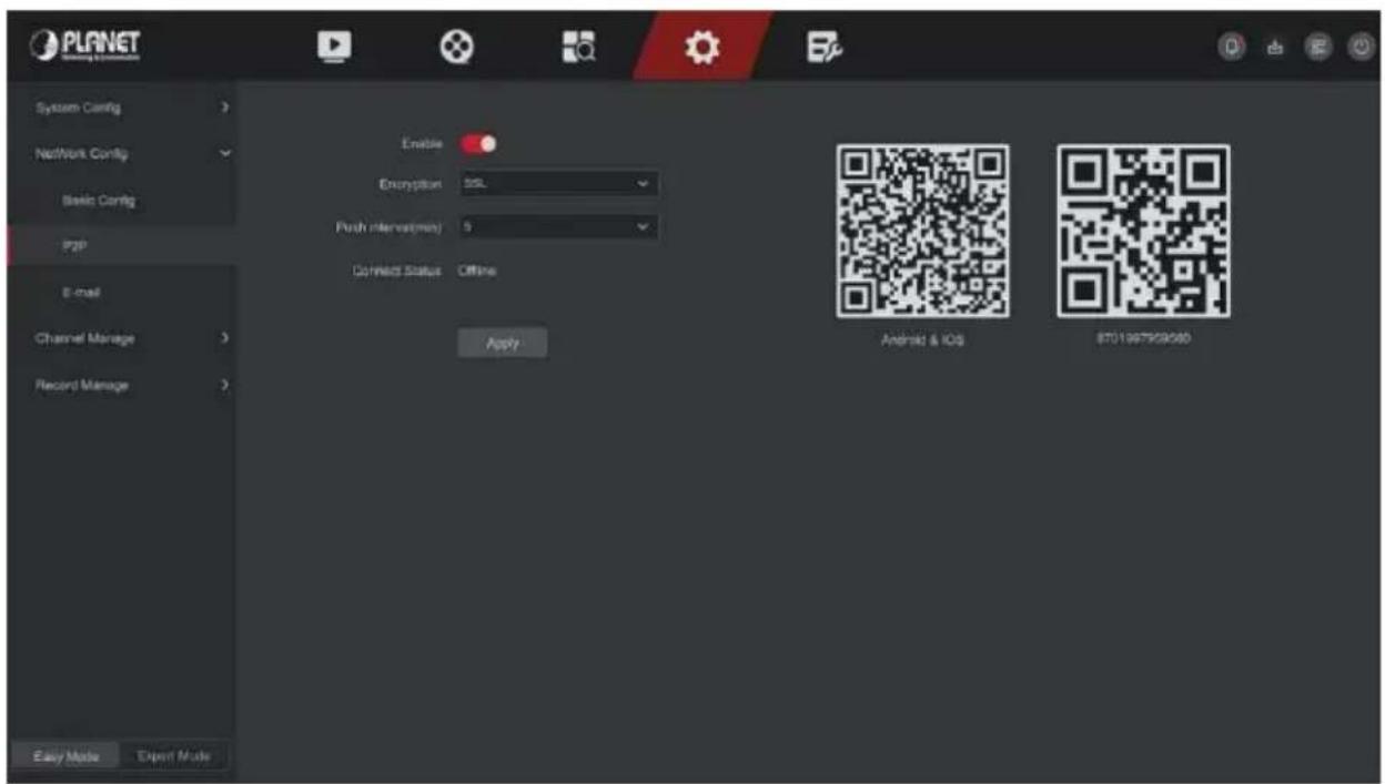
Figure 5-63
Step 2: Make sure that the NVR accesses the external network, choose "Enable P2P → Encryption".
Step 3: Click "Apply" to save the configuration.
Step 4: The connect status shows "Online". This indicates that P2P is enabled and can be used normally.
Connect Status: Display device P2P online status.
Enable: Turn on / off device P2P function, the default is "Online".
Encryption: Select the encryption type. After the device is enabled, all signaling communication between the device and the server is encrypted.
Push interval(min): Set the time interval for the device to snap the alarm picture to the mobile client, and you can also select "Turn off the push" to stop the device from pushing the picture to the mobile terminal.
Android &IOS: P2P client download link.
SN: Displays the serial number of the device P2P. This serial number is unique.
BitVision App Client operation example
"BitVision App" provides a micro video service platform for home and business users. Users can easily view real-time video, historical video, alarm service and other services.
The specific operation steps are as follows:
Step 1: Use the Android or iOS phone to scan the corresponding QR code to download and install the BitVision App.
Step 2: Run the client and log in to the account (No account is required to register first).
Step 3: Add devices to the mobile client.
After login, click "Device Management → + → SN Add ", Align the QR code on the device body or P2P interface to scan → enter the device username, password and verification code after scan the QR code (the verification code printed on the label), click "Add" to set device note and group, click "Send" after add successfully.
Step 4: Real-time preview
In the main interface, click "Real Time → ↑→ choose the device you want to view the preview, click "Done", choose a channel to play the real time video.
IPEYE
After enable the IPEYE for a channel of NVR, you can add the device to the IPEYE account, and view the real-time audio / video of the NVR channel through IPEYE.
The specific operation steps are as follows:
Step 1: In the main menu, choose "Config → Expert Mode → Network Config → P2P → IPEYE" to enter IPEYE setting interface, as shown in Figure 5-64 below.
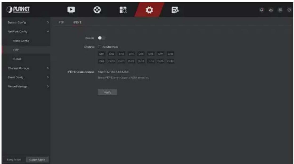
Figure 5-64
Step 2: choose "Config channel → Enable ", click "Apply", the IPEYE client IP address will be shown on the interface, as shown in Figure 5-65 below:
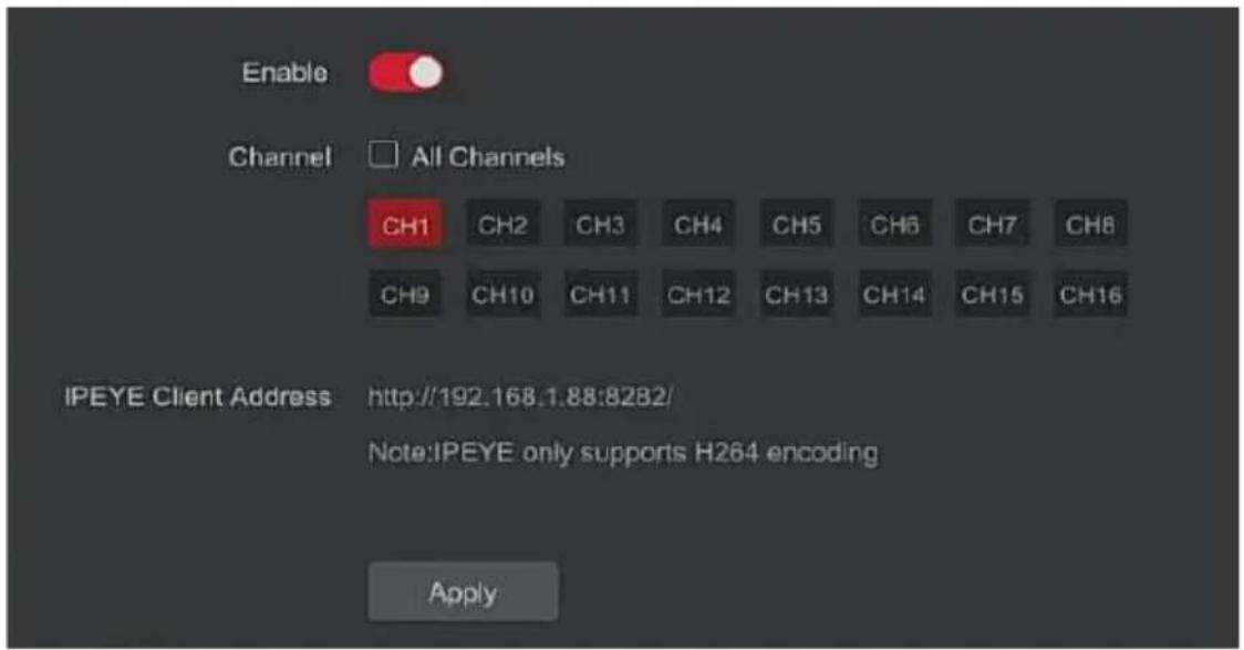
Figure 5-65
Step 3: Log in to IPEYE Client http://192.168.1.88:8282, enter the IPEYE and XVR accounts and passwords, select the device to enable IPEYE, and click "Add to Cloud" to add the device to the IPEYE account, as show in Figure 5-66
Add NVR to the Cloud

| # | Real Chanel | Cloud Chanel | Cloud Status | Action |
| 1 | 30 31 | Main: db0ecf91-af04-425a-9305-e75d610d836f/30 Second: db0ecf91-af04-425a-9305-e75d610d836f/31 | Wait | Add to Cloud |
| 2 | 00 01 | Main: db0ecf91-af04-425a-9305-e75d610d836f/00 Second: db0ecf91-af04-425a-9305-e75d610d836f/01 | Wait | Add to Cloud |
| 3 | 10 11 | Main: db0ecf91-af04-425a-9305-e75d610d836f/10 Second: db0ecf91-af04-425a-9305-e75d610d836f/11 | Wait | Success |
| 4 | 20 21 | Main: db0ecf91-af04-425a-9305-e75d610d836f/20 Second: db0ecf91-af04-425a-9305-e75d610d836f/21 | Wait | Add to Cloud |
Figure 5-66

- New user please log in http://www.ipeye.ru/ to register an account.
Step 3: Log in to http://www.ipeye.ru/ and enter the IPEYE device list to view the newly added device name as "cloud_xxxxx", and click " " to view the device real-time video.

- The IPEYE function only supports H264-encoded video streams. When the device channel is not H264-encoded, the real-time video of the channel cannot be previewed through IPEYE.
After setting the email information and enabling the alarm linkage email function, when the NVR triggers an alarm, the system sends an alarm email to the user mailbox.
The specific operation steps are as follows:
Step 1: On the main menu page, click "Config → Expert Mode → Network Config → E-mail" to enter the E-mail setting interface, as shown in Figure 5-67.
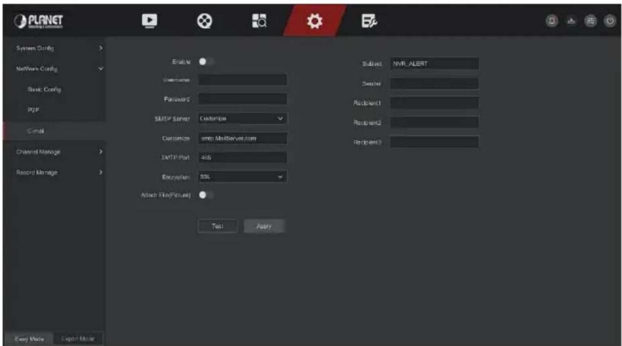
Figure 5-67
Step 2: Enable e-mail alarm notifications, configure SMTP server, SMTP port, user name, password, sender, subject, message interval, and select encryption type, attach file and other parameters.
Step 3: Click "Test" and the message "Success. Check the inbox." is displayed. Then the mail configuration is successful. If the message "E-mail can't be delivered!" is displayed, the mail configuration fails.
Step 4: After the email is sent successfully, click "Apply" to save the email configuration.
➢ Enable: Enable / disable mail sending.
➢ SMTP Server: Select the SMTP sever type.
SMTP Port: Please input corresponding port value here.
User Name: Please input the user name to login the sender email box.
➢ Password: Please input the corresponding password here.
Sender: Please input sender email box here.
➢ Recipient 1/2/3: Recipient e-mail address 1/2/3.
Subject: Please input email subject here. System support English character and Arabic number, default "XNVR_ALERT".
Encryption: Select the Mailbox server encryption, including NONE, SSL, TLS, and default "SSL".
Attach File: Turn on/off the email attachment function. After the alarm is turned on, the system can send snap shots when the alarm is sent.
Test: Test email sending and receiving functions are normal. In the correct configuration, the receiving email will receive a test email. When the test fails, check the parameters or network status.
5.6.2.3 Channel Manage
■ Channel Config
■ Add Device
After adding a remote device, you can view the video screen of the remote device directly on the NVR, and perform operations such as storage and management. Different devices support different numbers of remote devices. You can add required remote devices based on actual conditions.
Prerequisites:
Before adding the device, please confirm whether the IP camera has been connected to the network where the NVR is located and set its network parameters correctly.

CAUTION
- The device may face network security problems when it is connected to the Internet. Please strengthen the protection of personal information and data. When you find that the device may have hidden network security risks, please contact us in time. It is recommended that you conduct a periodic network security assessment of the device. Our company can provide corresponding professional technical services.
- Please understand that you are responsible for properly configuring all passwords and other related product security settings, and keeping your username and password properly.
The specific operation steps are as follows:
Step 1: In the main menu, click "Config → Expert Mode → Channel Manage → Channel Config" to enter Add Camera interface, as shown in Figure 5-68.
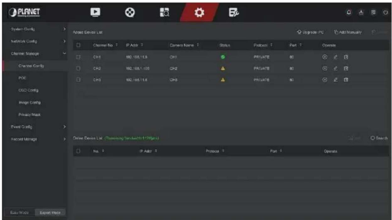
Figure 5-68
Step 2: Click "Refresh" device will search all IP cameras in the LAN and display the search results, as shown in Figure 5-69 below.
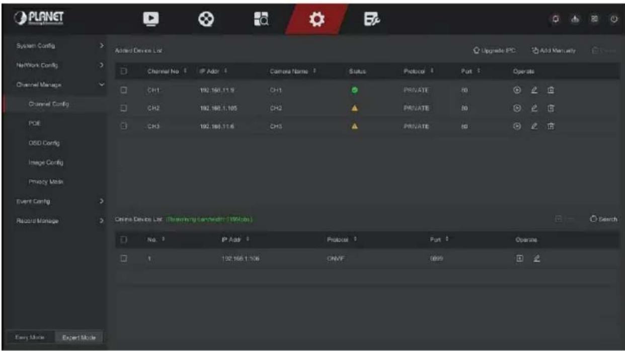
Figure 5-69
Step 3: Choose the device you want to add, click "Add", as shown in Figure 5-70 below.
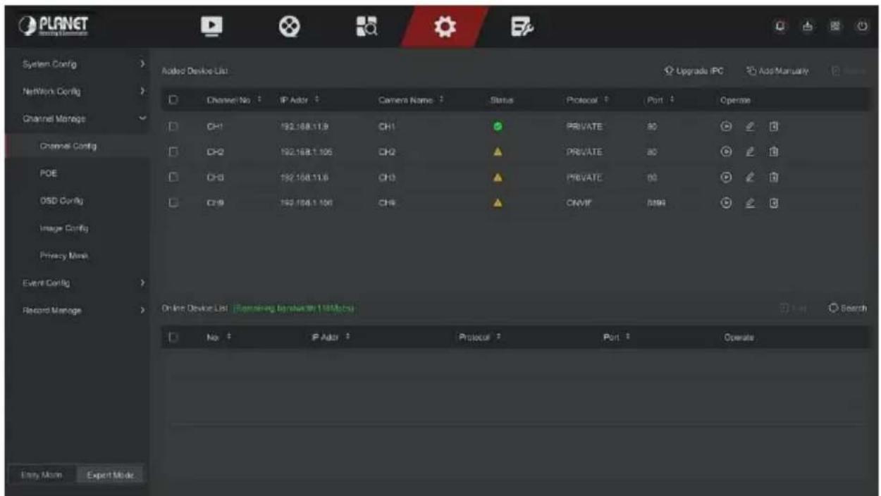
Figure 5-70
Auto Add: Click NVR to modify all camera IP and other network parameters in the LAN, and connect it to NVR.
Manual Add: Click to enter the "Channel Setup" interface. You can close the channel, switch, modify the protocol, switch the preview code stream or manually enter the device related information to add the device, as shown in Figure 5-71. Here are two methods of manually adding IP and domain name addition. When adding IPC through a domain name, only Private and ONVIF protocols are supported.
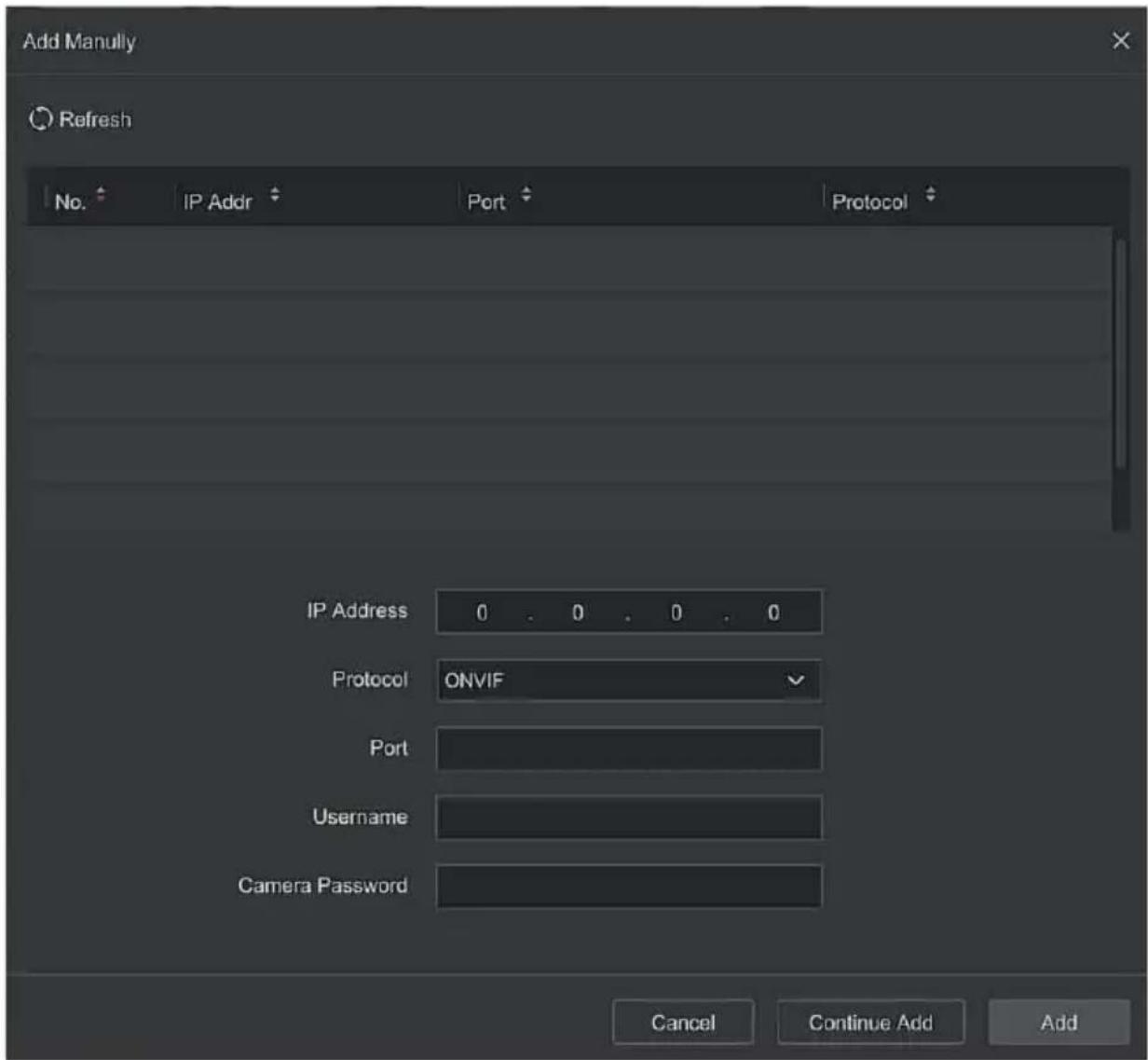
Figure 5-71
√ IP: Need to add IPC IP address.
√ Protocol: Select Add Device Protocol with Onvif, Private options.
√ Port: Access to the port used by IPC, the default is 80.
√ User Name: The login user name of IPC (if the defaulted user name is not admin, please change it to be valid user name).
√ Password: Login password of IPC (if the defaulted login password is not admin, please change it to be valid password).
Update IPC: Select one or more upgrade devices of the same type, insert the U disk storing the upgrade package of the device into the NVR, click "Upgrade", the system will find the upgrade package in the U disk and display it, select the upgrade package, click "Upgrade" to upgrade IPC in batches at the same time.
Delete: In the list of added devices, select the channel to be deleted and click the "Delete" button to delete all selected devices.
: Click and enter the channel setting interface, this function is the same as" manual add".
➢: Delete the current IPC from the device list.
Link: "✓" indicates that the connection is successful, and " &=" indicates that the connection fails. If the connection fails, the connection status will indicate the cause of the failure. If the password is incorrect, the user password will be incorrect.
▶: Click to view the screen of the corresponding channel.
■ OSD Config
OSD is the abbreviation of "On Screen Display", the OSD of local preview mainly includes time and channel name.
The specific operation steps are as follows:
Step 1: In the main menu, click "Config → Expert Mode → Channel Manage → OSD Config" to enter OSD config interface, as shown in Figure 5-72 below.
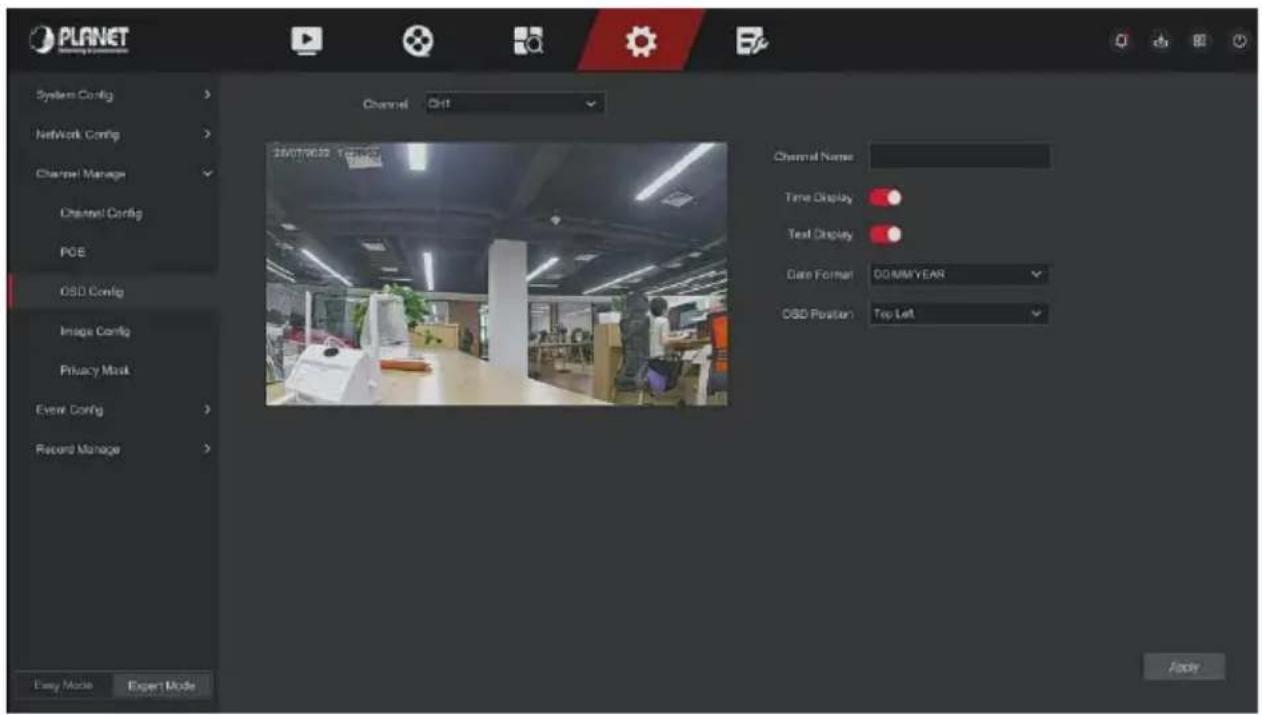
Figure 5-72
Step 2: Select the channel to set the OSD.
Step 3: Set the OSD of the channel.

- OSD includes channel name, time, text, date format, OSD position and mirror.
- The current OSD function only supports the private protocol to add the device to obtain and set.
Step 4: Click "Apply" to save the setting.
■ Image Config
In Image Color interface, the Brightness, Contrast, Saturation and Sharpness of IP channel video can be adjusted, related parameters for the IPC can also be set, such as Exposure, Day And Night Mode, Backlight Compensation, White Balance, Video Adjustment, Image Enhancement.
The specific operation steps are as follows:
Step 1: In the main menu, click "Config → Expert Mode → Channel Manage → Image Config" to enter Image config interface, as shown in Figure 5-73 below.
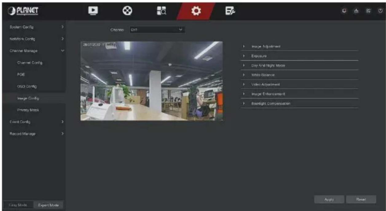
Figure 5-73
Step 2: Select the channel for image configuration.
Step 3: Adjust the image parameters of the channel.

- User can drag the slider to adjust the parameters.
- The Image adjustment, Fill light, Exposure setting, Backlight setting, White balance, Video adjustment, Image enhancement and Defog mode can be adjusted.
- Adjusting the parameters of the video will not only change the preview effect of the image, but also the video quality of the image, please operate with NOTE.
Step 4: Click "Apply" to save the setting.
Image Adjustment: According to the actual environment, you can adjust the brightness, contrast, saturation and sharpness of the preview screen by dragging the progress bar. You can also set the value behind the progress bar, "Brightness", "Contrast", "Saturation", "Sharpness". Valid values range from 0-255 and the default value is 128.
Exposure: Here you can see the aperture type of the camera, and set
the exposure time according to actual needs.
Day And Night: The default is auto, the sensitivity is 3, the filtering time is 3, the light brightness is 100. When the fill light mode is "Auto", the device will turn on the fill light according to the actual environment. The user can switch the fill mode to "Day", "Night" and "Scheduled switch" according to the actual video scene in the scene, and switch the sensitivity and filtering time of the device according to the fill mode. When the fill light mode is "Scheduled switch", you can set the daylight and dark time (ie, start and end fill time) and fill light brightness.
√ When the fill light mode is "Day", the fill light of the device is always off, and the camera is in color mode.
√ When the fill light mode is "Night", the fill light of the device is always on.
√ Filter time: It is used to prevent the ambient light from getting better and the light is frequently turned on and off, and the filtering time is set. During this time period, the camera is not disturbed by ambient light.
√ Light brightness: It is used to adjust the brightness of fill light, and the adjustable range is 0-100.
White balance: The default is auto. There are two types of switchable manual and automatic white balance, which can meet the needs of customers in different scenarios.
➢ Video adjustment: Here you can turn on mirroring, corridor mode and set the video format.
√ Mirror: The default is off, you can switch between vertical, horizontal, vertical and horizontal, when the device video image is upside down, you can flip the image through this menu.
√ Corridor Mode: It is disabled by default. When the corridor mode is enabled, the preview interface can be rotated by 90 degrees and 270 degrees.
√ Video Format: The default is 50HZ, you can select 60HZ in the drop-down menu, and you need to restart the device to switch the video format to take effect.
➢ Image enhancement: Here you can turn on and set wide dynamic, digital noise reduction, distortion, defog.
√ Wide Dynamic: The default is off, and you can select Low, Middle or High from the drop-down menu.
√ Digital Noise Reduction: The default is off, and you can select Low、Middle or High from the drop-down menu.
√ Distortion: The default is off, and you can select turn on from the drop-down menu.
√ Defog: The default is off, and you can select Low, Middle or High from the drop-down menu.
Backlight Compensation: Used to set backlight compensation and strong light compensation.
√ Backlight Compensation: The default is off, and you can select Left, Right, Up, Down or Middle from the drop-down menu.
√ Strong Light Compensation: The default is off, and you can select turn on from the drop-down menu.

- The camera image interface only displays the device support functions. The specific interface is subject to the actual product.
■ Privacy Mask
The function of privacy mask can block certain sensitive or privacy-related areas in the monitoring scene image.
The specific operation steps are as follows:
Step 1: In the main menu, click "Config → Expert Mode → Channel Manage → Privacy Mask" to enter Privacy Mask interface, as shown in Figure 5-74
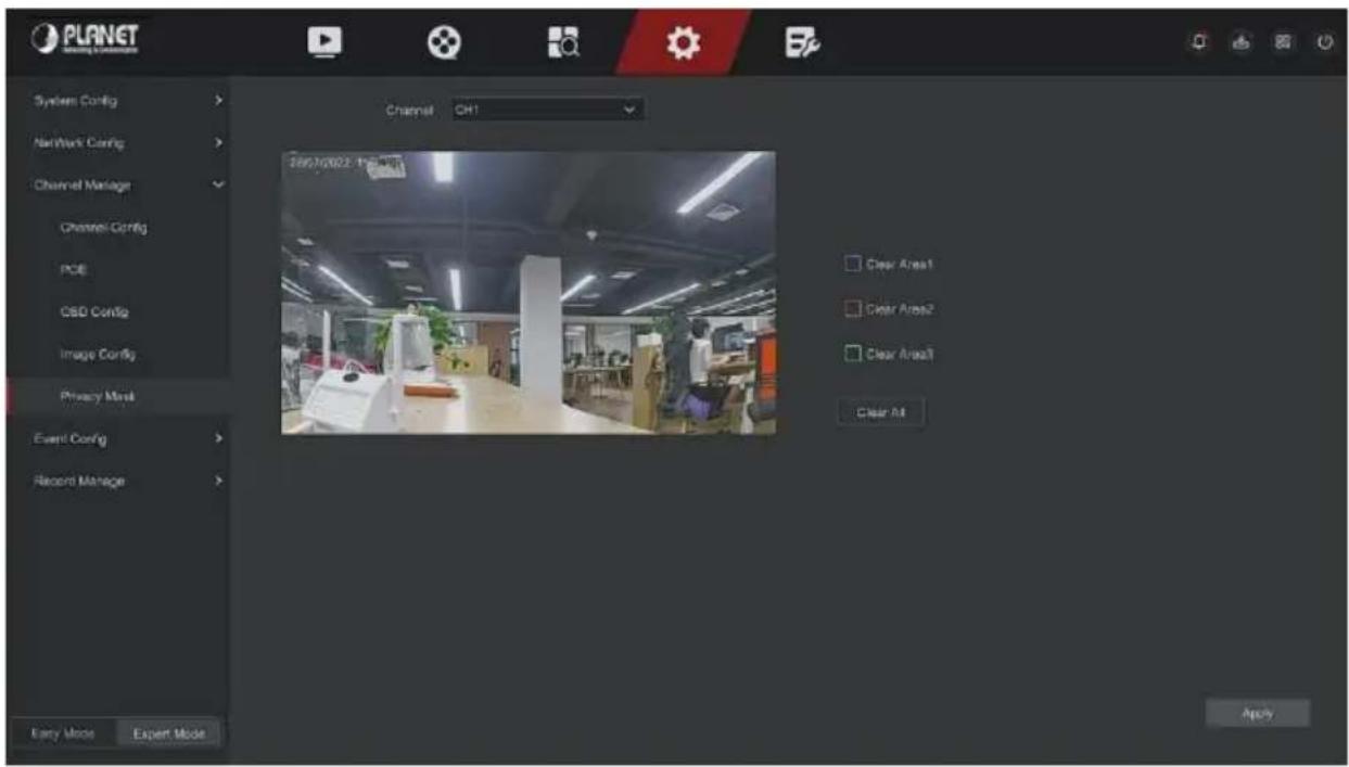
Figure 5-74
Step 2: Select the channel for video occlusion.
Step 3: Use the mouse to define the occlusion area in the video, as shown in Figure 5-75 below.
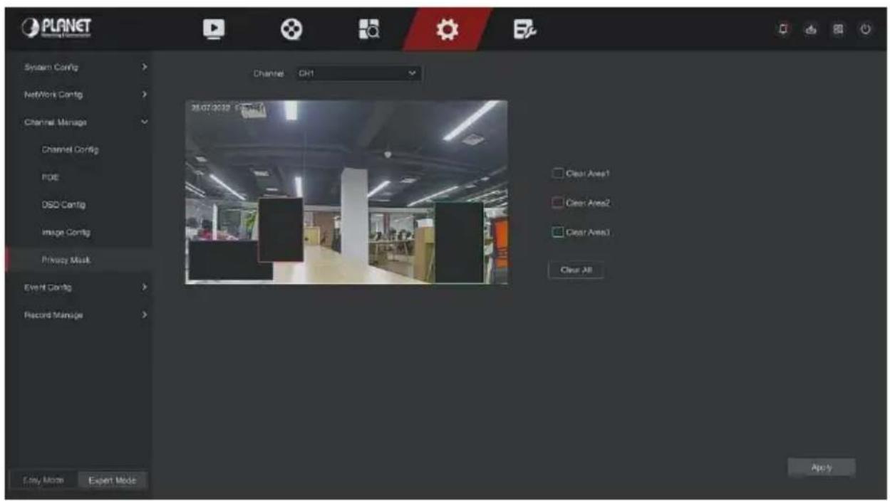
Figure 5-75
Step 4: Click "Apply" to save the setting.
▶ Channel: Select Set Channel.
Clear All: Clear all selected areas masks.
Clear Zoom1, 2, 3: Clear the selected occlusion area 1, 2, 3.

- Up to 3 occlusion areas can be set. Click clear area X to delete this area setting.
5.6.2.4 Event Config
■ Ordinary Event
■ Motion Detection / Video Tampering
Motion detection uses computer vision and image processing techniques to analyze the video images to see if there are enough changes in the images. When the moving target appears on the monitoring screen and the moving speed reaches the preset sensitivity, the system performs an alarm linkage action.
The specific operation steps are as follows:
Step 1: In the main menu, choose "Config → Expert Mode → Event Config → Ordinary Event → Motion Detection / Video Tampering" to enter Motion Detection interface, as shown in Figure 5-76 below.
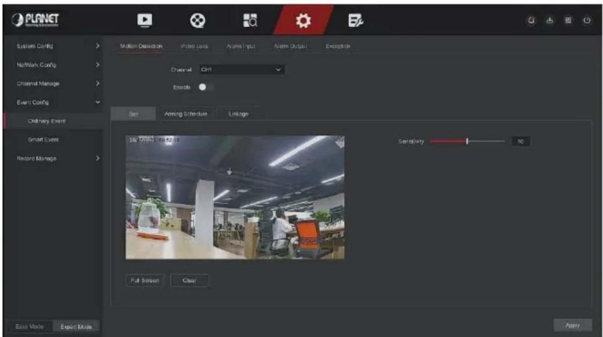
Figure 5-76
Step 2: Turn on motion detection and select a channel.
Step 3: Set area, sensitivity.
√ Use the mouse to draw the area that needs motion detection on the channel video, as shown in Figure 5-77 below.
√ Slide the sensitivity slider to select the appropriate motion detection sensitivity.
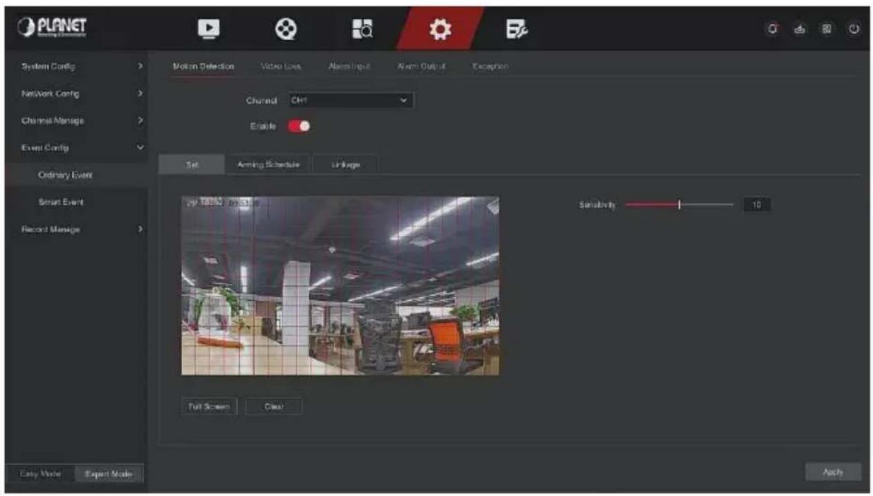
Figure 5-77
Step 4: Click "Arming Schedule" to enter Arming Schedule interface, as shown in Figure 5-78 below. Draw the arming time in the drawing area, or click "Edit Time" to set the day of the week and time period 1\~8.
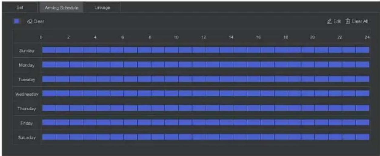
Figure 5-78
Step 5: Click "Linkage" to enter Linkage interface, set normal linkage and alarm output as required, as shown in Figure 5-79 below.
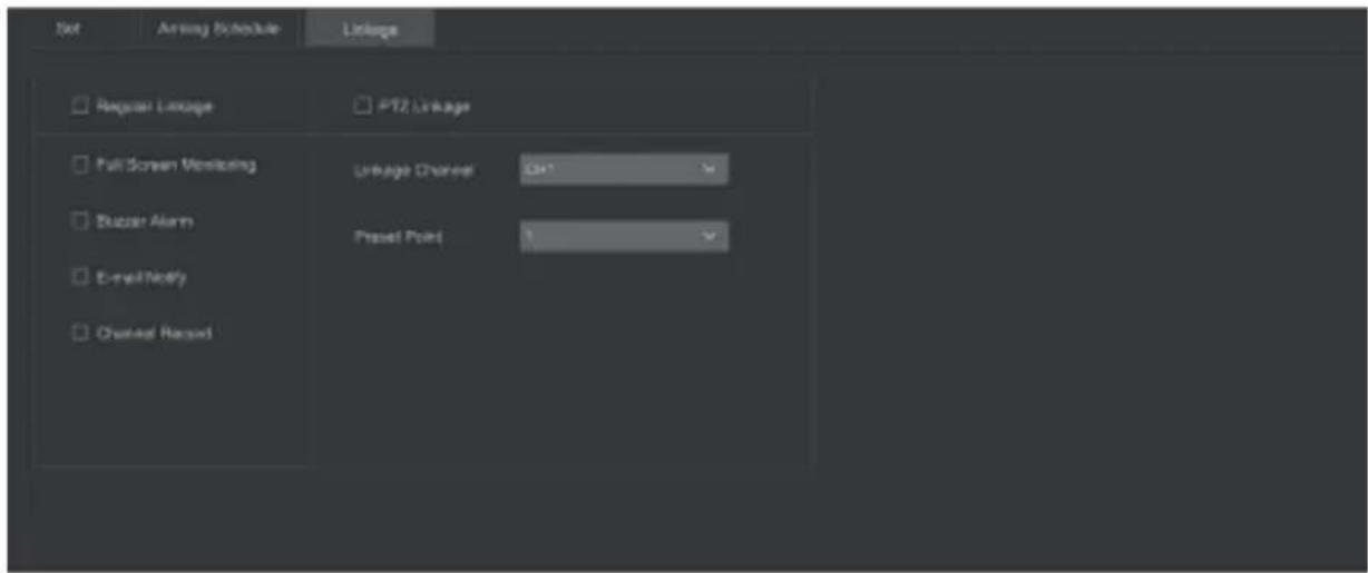
Figure 5-79
Step 6: Click "Apply" to save the setting.

Note
- If you need to set motion detection for other channels, please repeat the above steps.
- After setting to enable email notification for motion detection, click "Config → Network Config → E-mail" to enter E-mail setting interface to set up the email. When the system sends a linkage alarm within the set time period, the recipient receives the alarm email.
- After enabling email notification, after setting the specific week and time period, only when the alarm is triggered within the set time period, the NVR can send an email to the set mailbox to notify the user.
- If the other channels have the same motion detection settings as that channel, click "Copy", select another channel, and copy the settings of this channel to other channels.
➢ Channel: Select to set the channel.
Enable: Check " " to turn on / off motion detection alarm.
Set Area: Select all areas by default, click to enter the area setting interface, set the range of the dynamic detection area, press and hold the left mouse button to select the alarm area. After selection, the alarm area is replaced by the red grid. Select the red grid again to cancel the alarm area setting.
Sensitivity: According to the need, can be set 0-10 eleven file sensitivity, the higher the value, the more sensitive the device.
Edit: Click to enter the Arming Schedule interface, you can manually set 8 time periods for recording every day, and copy the settings to other times through "Copy To".
Buzzer Alarm: Check "☐" to turn on / off the buzzer alarm function.
E-mail Notify: Check "☐" to turn on / off when the device alerts the mail function.
Channel Record: Check "☐" to turn on / off the channel recording function.
Full Screen Monitoring: When an alarm is triggered on the preview interface, the real-time video of the device channel is displayed in full screen.
PTZ Linkage: When an alarm occurs, link the PTZ channel to the specified preset point.
■ Video Loss
When there is a channel losing video signal, the device will alarm and notify the user.
The specific operation steps are as follows:
Step 1: In the main menu, choose "Config → Expert Mode → Event Config → Video Loss" to enter Video Loss interface, as shown in Figure 5-80 below.
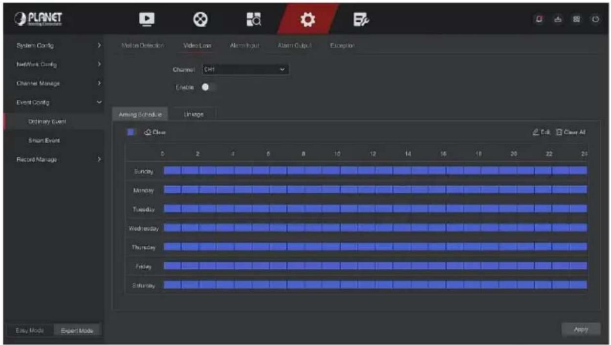
Figure 5-80
Step 2: Choose a channel, and enable the video loss.
Step 3: Set the arming time and linkage mode as needed.
Step 4: Click "Apply" to save the setting.
Screen Tips: When an alarm occurs, the device pops up an alarm screen to show a warning.
E-mail Notify: When an alarm occurs, the device will send an email as a warning.
Buzzer Alarm: When an alarm occurs, the device will beep to show a warning.
PTZ Linkage: When an alarm occurs, link the PTZ channel to the specified preset point.
■ Exception
Set the alarm mode of abnormal events. When an abnormal event occurs during the operation of the NVR device, the system executes the alarm linkage action. The event types supported by the device are "No Disk", "Disk Error", "Broken Network" and "IP Conflict".
The specific operation steps are as follows:
Step 1: In the main menu, choose "Config → Expert Mode → Event Config → Exception" to enter Exception setting interface, as shown in Figure 5-81 below.
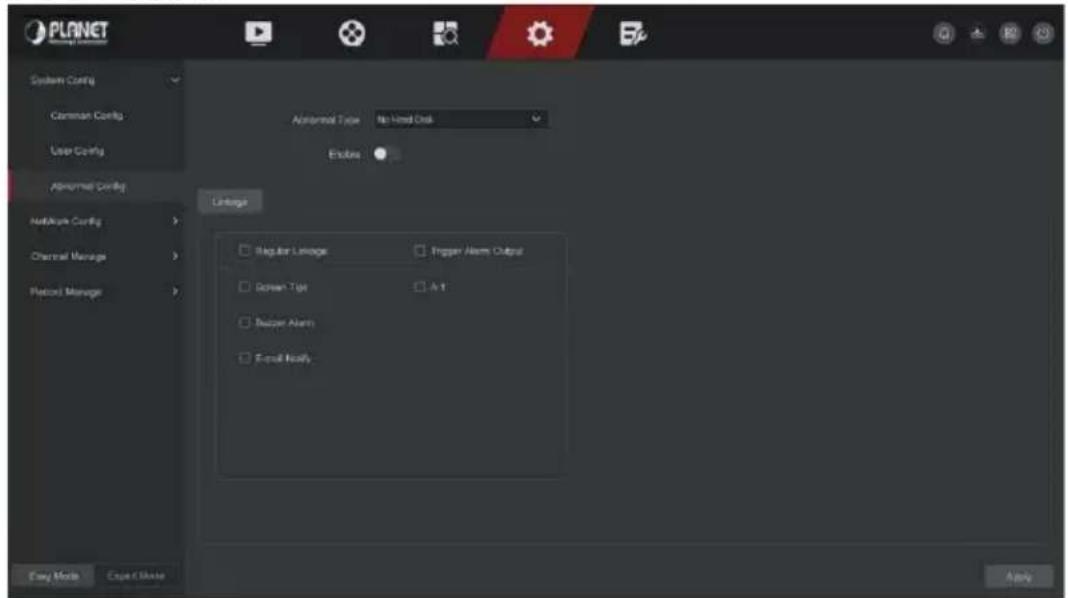
Figure 5-81
Step 2: Select the event type, click "☐" to enable the exception alarm function, choose the way for linkage (Screen Display, E-mail Notification, and Buzzer Alarm) and alarm output port.
Step 3: Click "Apply" to save the setting.
Screen Tips: When an alarm occurs, the device pops up an alarm screen to show a warning.
E-mail Notify: When an alarm occurs, the device will send an email as a warning.
➢ Buzzer Alarm: When an alarm occurs, the device will beep to show a warning.
Smart Event
■ Line Crossing
Line crossing detection can detect whether there is an object crossing the set warning surface in the video, and perform linkage alarm according to the judgment result.
The specific operation steps are as follows:
Step 1: In the main menu, choose "Config → Expert Mode → Event Config → Smart Event" to enter Smart Event setting interface.
Step 2: Choose the channel you need to set the line crossing detection, click "Line Crossing" to enter line crossing detection setting mode, as shown in Figure 5-82 below.
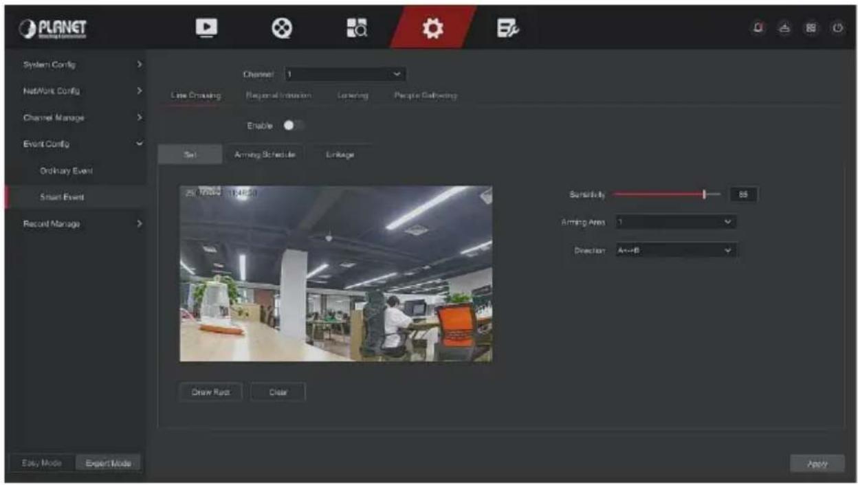
Figure 5-82
Step 3: Click "Enable → Set", to set the rule of line crossing detection, the specific steps are shown as below:
- In the "Rules" drop-down list, select any rule as you need. Line crossing detection can set 4 rules.
- Set the direction and sensitivity.
Sensitivity: It is used to set the size of the control target object. The higher the sensitivity, the easier the object is judged to be the target object. The lower the sensitivity, the larger the object will be judged as the target object. The sensitivity can be set in the range of 0-100.
Direction: There are three options: "A <-> B (bidirectional)", "A-> B", "B-> A", which refers to the direction in which an object passes through the warning area to trigger an alarm.
√ "A<->B (Bidirectional)" Indicates that the alarm is triggered in both directions.
√ "A->B" Indicates that the object will trigger an alarm when it crosses from A to B.
√ "B->A" Indicates that the object will trigger an alarm when it crosses from B to A.
-
Click "Draw Rect", move the mouse to the preview screen and click the left mouse button in sequence to draw the two endpoints of the warning line.
-
You can modify the drawn warning line through the "Clear".
Step 4: Click "Arming Schedule", Set the alarm arming time, as shown in Figure 5-83 below.
Figure 5-83
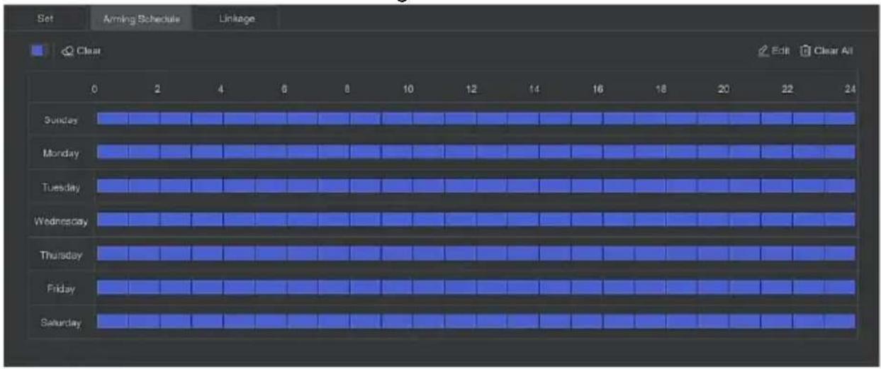
Step 5: Click "Linkage", set alarm linkage as required (Buzzer alarm, email notification, channel recording, screen prompt) and alarm output and PTZ linkage, as shown in Figure 5-84 below.
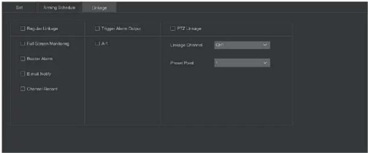
Figure 5-84
Step 6: Click "Apply" to save the setting.
■ Regional Intrusion
The regional intrusion function can detect whether an object in the video enters the set area, and conduct a linkage alarm based on the judgment result.
The specific operation steps are as follows:
Step 1: In the main menu, choose "Config → Expert Mode → Event Config → Smart Event" to enter SmartEvent setting interface.
Step 2: Choose the channel you need to set the regional intrusion, click "Regional Intrusion" to enter regional intrusion setting mode, as shown in Figure 5-85 below.
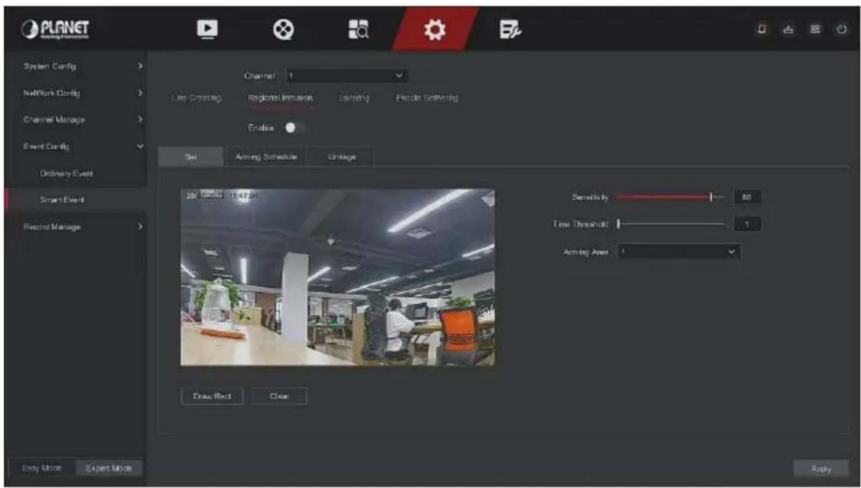
Figure 5-85
Step 3: Click "Enable → Set ", to set the rule of regional intrusion detection, the specific steps are shown as below:
- In the "Rules" drop-down list, select any rule as you need. Regional intrusion detection can set 4 rules.
- Set the time threshold and sensitivity.
Sensitivity: It is used to set the size of the control target object. The higher the sensitivity, the easier the object is judged to be the target object. The lower the sensitivity, the larger the object will be judged as the target object. The sensitivity can be set in the range of 0-100.
Time Threshold (s): An alarm is generated after the target enters the warning zone for a continuous dwell time. If the time threshold is set to 5 seconds, the target intrusion zone is triggered for 5 seconds. The range is 1-10 (seconds).
3. Click "Draw Rect", move the mouse to the preview screen and click the left mouse button in sequence to draw the endpoints of the quadrilateral warning zone to complete the zone drawing.
4. You can modify the drawn warning line through the "Clear".
Step 4: Click "Arming Schedule", Set the alarm arming time, as shown in Figure 5-86 below.
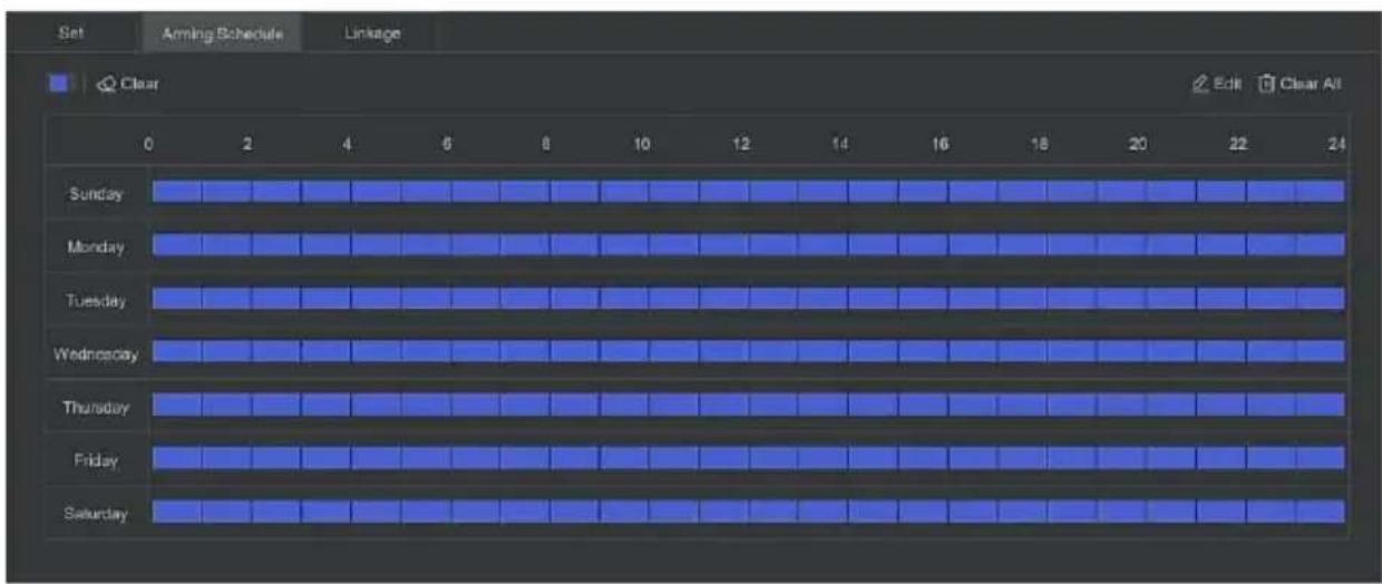
Figure 5-86
Step 5: Click "Linkage", set alarm linkage as required (Buzzer alarm, email notification, channel recording, screen prompt) and alarm output and PTZ linkage, as shown in Figure 5-87 below.
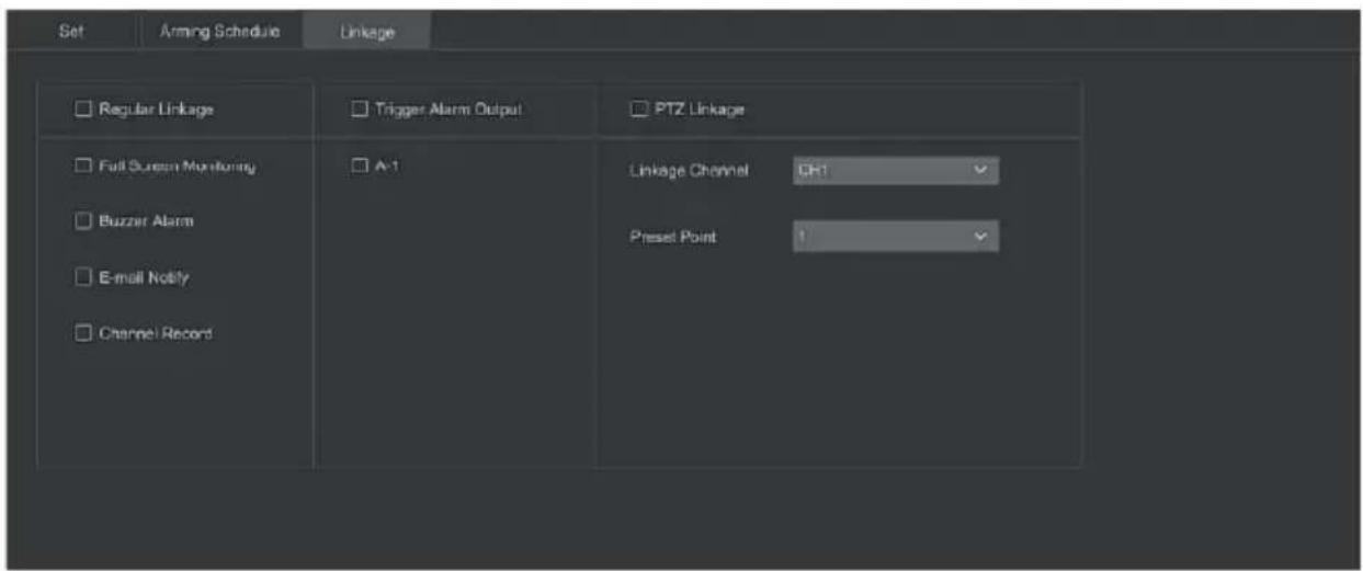
Figure 5-87
Step 6: Click "Apply" to save the setting.
■ Loitering
The loitering function can detect the stay time of the target in the set area. When the stay time exceeds the set time threshold, an alarm linkage will be triggered.
The specific operation steps are as follows:
Step 1: In the main menu, choose "Config → Expert Mode → Event Config → Smart Event" to enter Smart Event setting interface.
Step 2: Choose the channel you need to set the loitering, click "Loitering" to enter loitering setting mode, as shown in Figure 5-88 below.
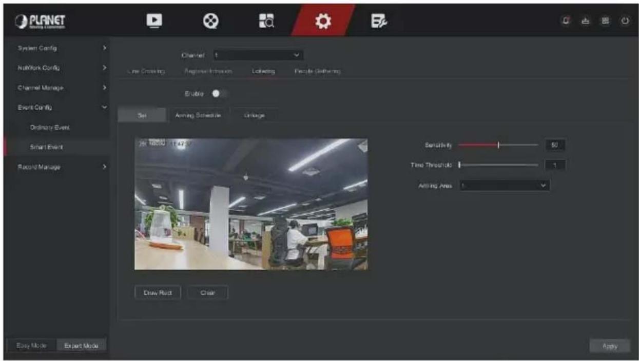
Figure 5-88
Step 3: Click "Enable → Set", to set the rule of loitering intrusion detection, the specific steps are shown as below:
- In the "Rules" drop-down list, select any rule as you need. Loitering detection can set 4 rules.
- Set the time threshold and sensitivity.
Sensitivity: It is used to set the size of the control target object. The higher the sensitivity, the easier the object is judged to be the target object. The lower the sensitivity, the larger the object will be judged as the target object. The sensitivity can be set in the range of 0-100.
Time Threshold (s): An alarm is generated after the target enters the warning zone for a continuous dwell time. If the time threshold is set to 5 seconds, the target intrusion zone is triggered for 5 seconds. The range is 1-10 (seconds).
-
Click "Draw Rect", move the mouse to the preview screen and click the left mouse button in sequence to draw the endpoints of the quadrilateral warning zone to complete the zone drawing.
-
You can modify the drawn warning line through the "Clear".
Step 4: Click "Arming Schedule", Set the alarm arming time, as shown in Figure 5-89 below.
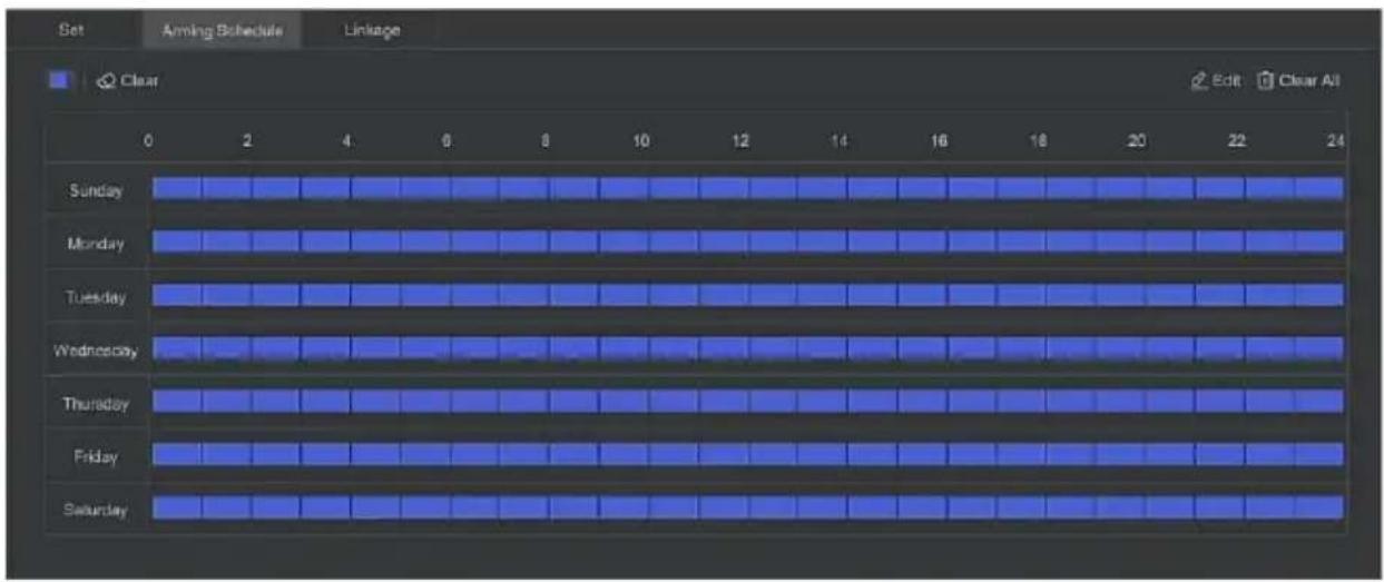
Figure 5-89
Step 5: Click "Linkage", set alarm linkage as required (Buzzer alarm, email notification, channel recording, screen prompt) and alarm output and PTZ linkage, as shown in Figure 5-90 below.
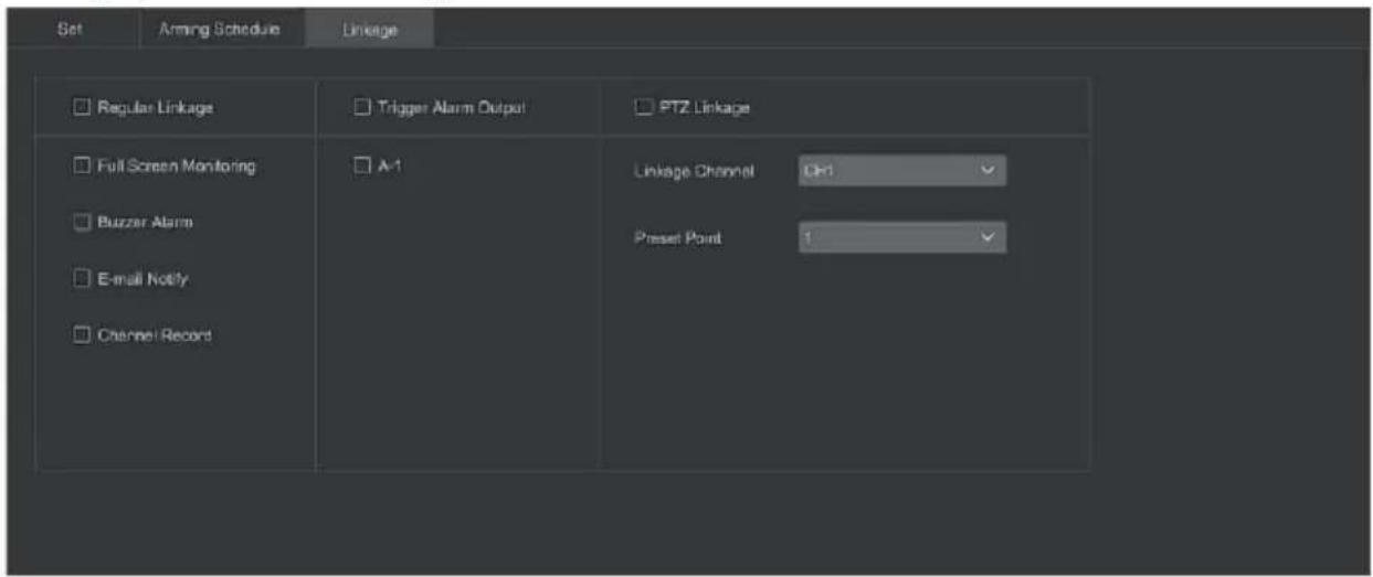
Figure 5-90
Step 6: Click "Apply" to save the setting.
■ People Gathering
The people gathering function can detect the density of the human body in the set area, if it exceeds the set threshold, it will trigger an alarm linkage.
The specific operation steps are as follows:
Step 1: In the main menu, choose "Config → Expert Mode → Event Config → Smart Event" to enter SmartEvent setting interface.
Step 2: Choose the channel you need to set the people gathering, click "People Gathering" to enter people gathering setting mode, as shown in Figure 5-91 below.
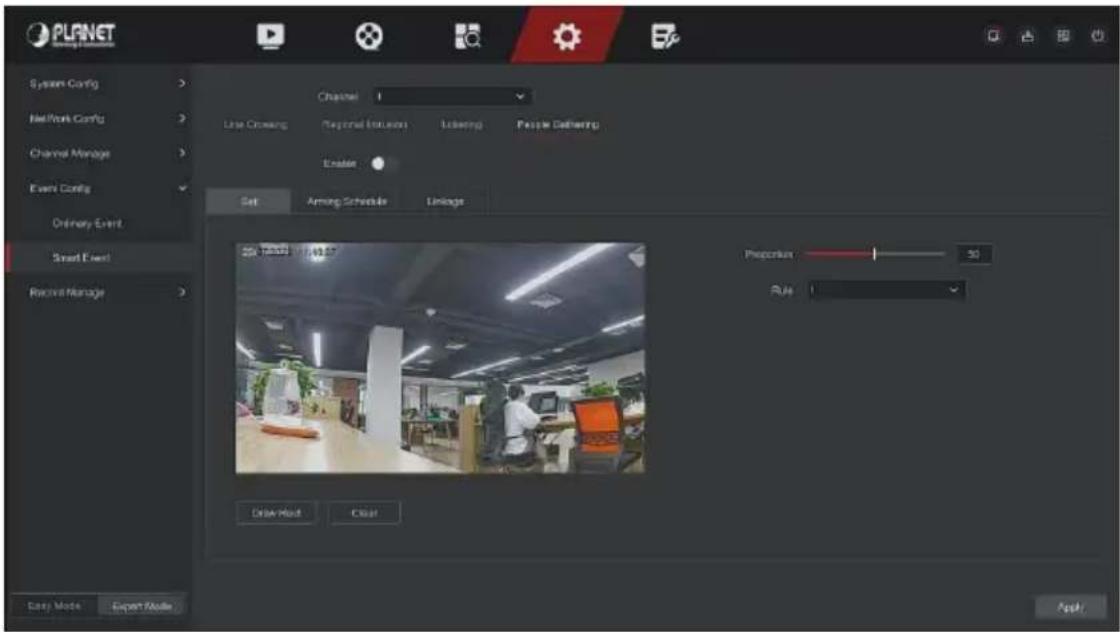
Figure 5-91
Step 3: Click "Enable → Set", to set the rule of people gathering, the specific steps are shown as below:
- In the "Rules" drop-down list, select any rule as you need.
- Set the proportion of rules.
Proportion: Represents the proportion of personnel in the entire warning area, when the proportion of personnel exceeds the set proportion value, the system alarm is triggered, otherwise the system does not alarm.
3. Click "Draw Rect", move the mouse to the preview screen and click the left mouse button in sequence to draw the endpoints of the quadrilateral warning zone to complete the zone drawing.
4. You can modify the drawn warning line through the "Clear".
Step 4: Click "Arming Schedule", Set the alarm arming time, as shown in Figure 5-92 below.
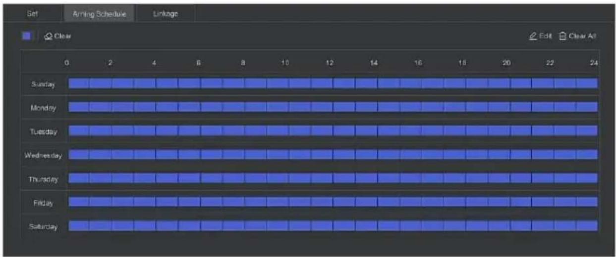
Figure 5-92
Step 5: Click "Linkage", set alarm linkage as required (Buzzer alarm, email notification, channel recording, screen prompt) and alarm output and PTZ linkage, as shown in Figure 5-93 below.
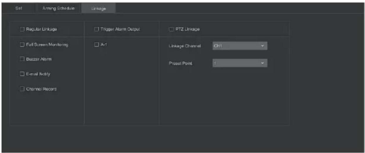
Figure 5-93
Step 6: Click "Apply" to save the setting.
5.6.2.5 Record Manage
Record Plan
NVR supports two recording plan, drawing method and editing method.
■ Set the recording plan by drawing method
The specific operation steps are as follows:
Step 1: In the main menu, click "Config → Expert Mode → Record Manage → Record Plan" to enter record plan setup interface, as shown in Figure 5-94 below.
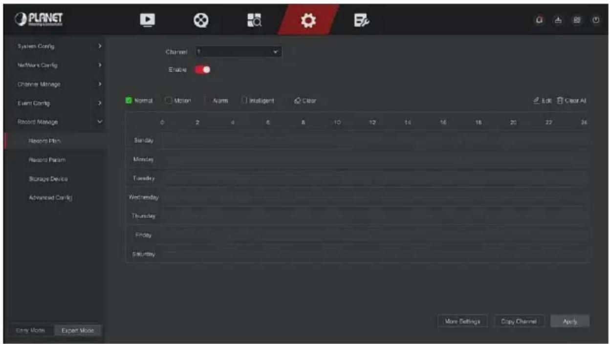
Figure 5-94
Step 2: According to the needs of recording, select channel, enable, recording type (Normal, Motion, Alarm, Intelligent), week and other options Step 3: Click the left mouse button to locate the starting point of the drawing area, drag the mouse to determine the time of the recording plan, release the left mouse button to save as a recording plan, as shown in Figure 5-95 below.
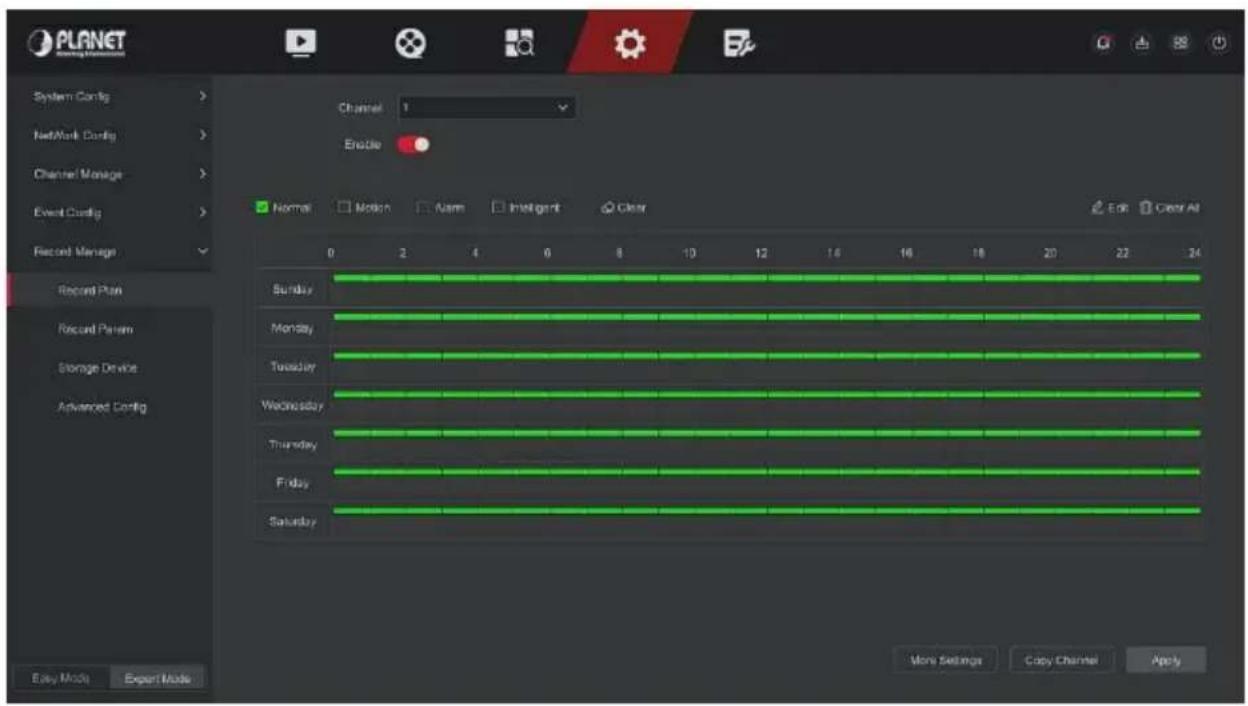
Figure 5-95
Step 4: Repeat step 3 to set up a complete recording plan.
Step 5: After the recording plan is set, the channel presents the type (color) of the recording plan, as shown in Figure 5-96 below.
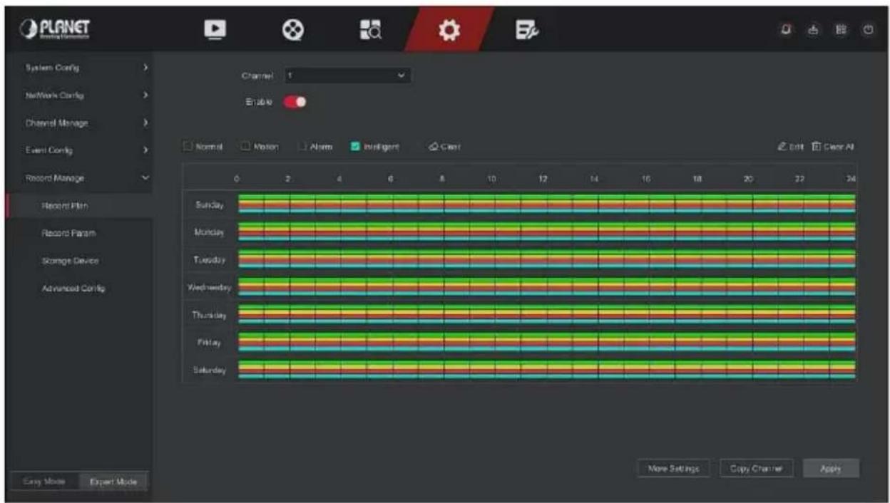
Figure 5-96

Note
- There are 6 time periods available for each day, and the device will start the corresponding type of recording within the set time range.
● The smallest unit of the drawing area is 1 hour. - Press and hold the left mouse button in the drawing area, then drag the box to select, you can edit the time period of each day of the week synchronously.
■ Set the recording plan by editing method The specific operation steps are as follows:
Step 1: In the main menu, click "Config → Easy Mode → Record Manage → Record Plan" to enter record plan setup interface.
Step 2: Click "Edit" to enter "Modify Schedule" setting interface, as shown in Figure 5-97 below.
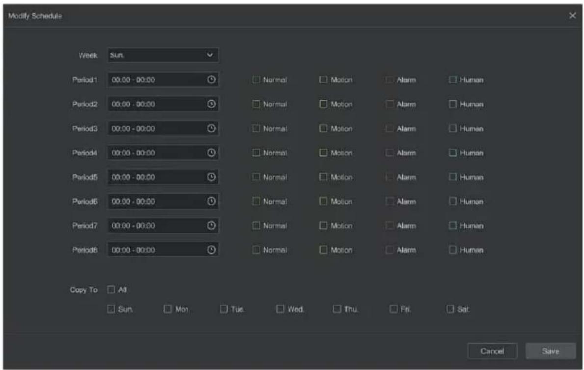
Figure 5-97
Step 3: Select the recording type of each time period. There are eight time periods for setting each day. Select the corresponding week in "Save" to apply to the corresponding week.
Step 4: Click "Save" to complete the setting, the system will return to "Record" interface.
Record Type: Select check the box to select corresponding record type. There are Normal, Motion, Alarm, and Intelligent.
Week day: Select the week number. If you select "All", it means to the entire week, or you can select "in front of the number of days to set individual days.
More Settings: You can set the prerecord time(s) and post-record(s), as shown in Figure 5-98 below.
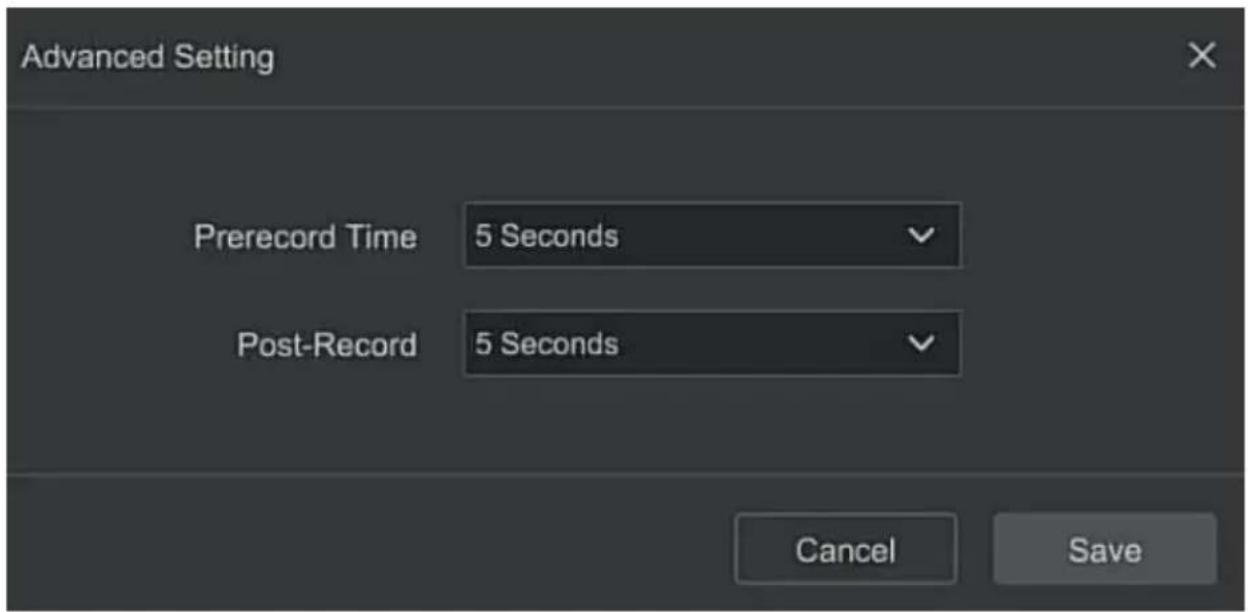
Figure 5-98
Copy Channel: After complete the setup, you can click "Copy Channel" button to copy current setup to other channel(s), as shown in Figure 5-99.
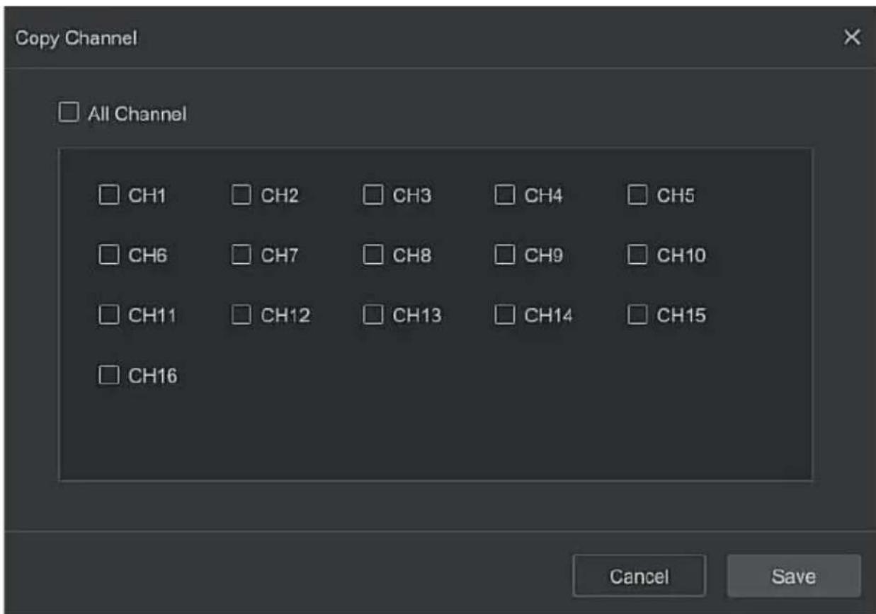
Figure 5-99
■ Record Param
Record Param interface is used for recording parameter configuration.
The specific operation steps are as follows:
Step 1: In the main menu, click "Config → Expert Mode → Record Manage → Record Param" to enter record param setup interface, as shown in Figure 5-100 below.
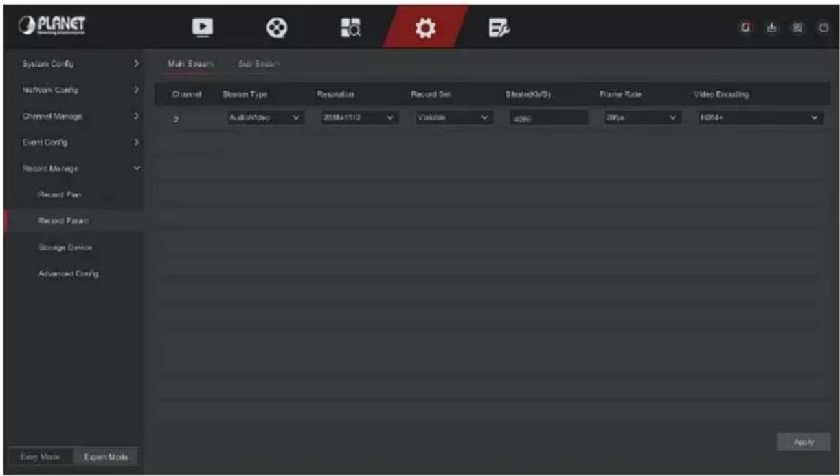
Figure 5-100
Step 2: Set recording parameters, please refer to Table 5-6 for specific parameter descriptions.
| Name | Details | Setting |
| Channel | Select the channel to set recording parameters | |
| Record Set | There are two types of video compression parameters: Main Stream (timing) and Main Stream (Event). Main Stream (timing): Encoding parameters for ordinary recording. Main Stream (Event): Encoding parameters for events such as motion detection, alarm input, and smart detection | NOTE: The event parameters cannot be set and are consistent with the timing parameters. |
| Resolution | Resolution refers to the number of pixels contained in a unit length. | Select through the drop-down box. NOTE: The encoding resolution is related to the IP device. |
| Stream Type | The stream type is Video & Audio (composite stream), and the recording information includes video and audio. | Select through the drop-down box. |
| Frame Rate | Video frame rate refers to the number of video frames per second | Adjust via slider. |
| Bitrate(Kb/S) | Set the code stream value to change the quality of the image quality, the larger the code stream, the better the image quality. | Modify it directly in the input box. |
| Video Encoding | H264, H265,H264+,H265+ | Select through the drop-down box. NOTE: The encoding type is related to the IP device. |
Table 5-6
Step 3: Click "Apply" to save the setting.
■ Storage Device
■ Disk Management
The storage device is used to format the hard disk and view the hard disk's applicable status and capacity.
Formatting the hard drive
Prerequisites:
The user has installed the hard disk correctly. For details of the hard disk installation procedure, please refer to the "NVR Quick Start Guide".
The specific operation steps are as follows:
Step 1: In the main menu, click "Config → Expert Mode → Record Manage → Storage Device" to enter storage device interface, as shown in Figure 5-101 below.
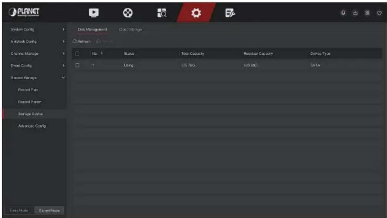
Figure 5-101
Step 2: Select the hard drive that needs to be formatted, click "Format", as shown in Figure 5-102 below.
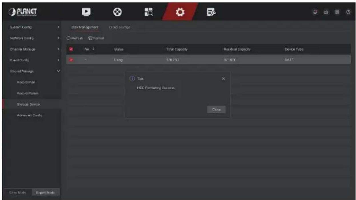
Figure 5-102
Step 3: Wait for the formatting progress bar to finish, click "Close", the NVR will restart and complete the format. The status of the hard disk is "Using" at this time.
No.: The number of HDD that connect the system.
State: Detect the current working status of HDD, you could use only that displays "In use"; after formatting is completed, you need to restart NVR, the status displays "In use".
Total Capacity: The total available HDD capacity, the single HDD capacity can't exceed the maximum capacity: 8TB.
Residual Capacity: Display the residual capacity of the current HDD;
Device Type: SATA.
Refresh: Click update disk list information.

- "No Disk" indicates that the device is not connected or the hard disk isn't detected.
- The hard disk must be formatted first when the hard disk is connected to the NVR for the first time or when "Not formatted" is displayed.
- The device does not need to format the hard disk when the hard disk status shows "In Use".
● After formatting the hard disk, restart the NVR to takes effect.
■ Cloud Storage
Set cloud storage. When the device triggers an alarm, it can store the captured alarm image of the device on the cloud server.
Prerequisites:
1) You need to have a Google Cloud Storage account.
2) Using this function, the device must be connected to an external network; otherwise it will not work properly.
The specific operation steps are as follows:
Step 1: On the main menu page, select "Config → Easy Mode →
Record Manage → Storage Device → Cloud Storage " to enter the cloud storage setting interface, as shown in Figure 5-103.
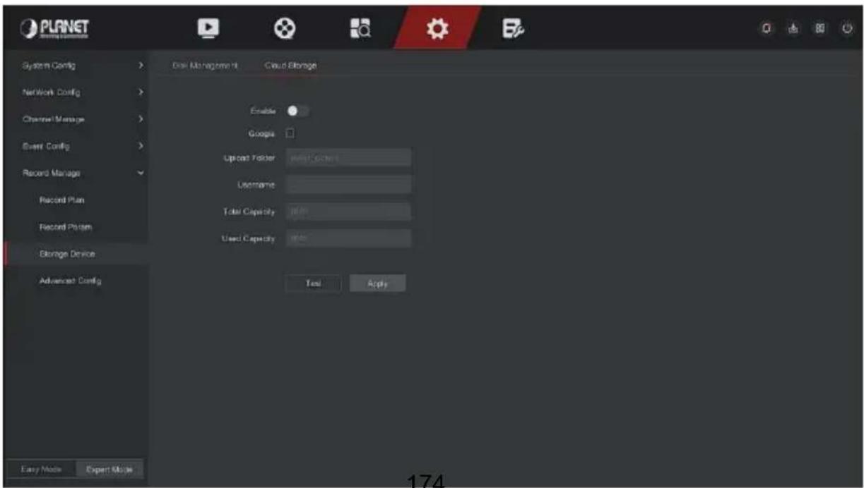
Figure 5-103
Step 2: Select "Enable → Google" to obtain the "Authorization Code". Follow the prompts to log in to the website on the computer and enter the "Authorization Code" to bind the Google server cloud service.
Step 3: Click "Apply".
Step 4: Click "Test" to test whether the XVR can successfully upload files to the cloud server. After the binding is successful, the cloud storage interface displays the "Google" username, total capacity, and used space.
Enable: Turn on/off the device cloud storage function.
Google: Select a cloud storage type and enter the binding interface.
Upload Folder: Set the upload cloud space folder name.
Username: Displays the user name of the Google.
Total Capacity: After the cloud storage binding is successful, the total capacity of the cloud space is displayed.
Used Capacity: Cloud storage binding is successful; the display of cloud space has been used capacity.
Test: After binding, click "Test" to confirm whether the binding is successful. If the test fails, check whether the device is properly connected to the network and the cloud storage configuration.
■ Advanced Config
- Configure
In the configuration interface, you can view and set related information such as NVR disk full and automatic deletion of recordings.
The specific operation steps are as follows:
Step 1: On the main menu page, click "Config → Expert Mode → Record Manage → Advanced Config → Configure" to enter the configure interface, as shown in Figure 5-104 below.
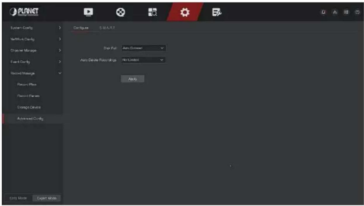
Figure 5-104
Step 2: Set the device disk full mode and the time to automatically delete recordings as needed.
■ S.M.A.R.T
S.M.A.R.T is used to monitor the temperature of the hard disk, the surface material of the disk, the motor and its drive system, and analyze and predict the possible problems of the hard disk.
The specific operation steps are as follows:
Step 1: In the main menu, choose "Config → Expert Mode → Record Manage → Advanced Config → S.M.A.R.T" to enter S.M.A.R.T interface, as shown in Figure 5-106 below.
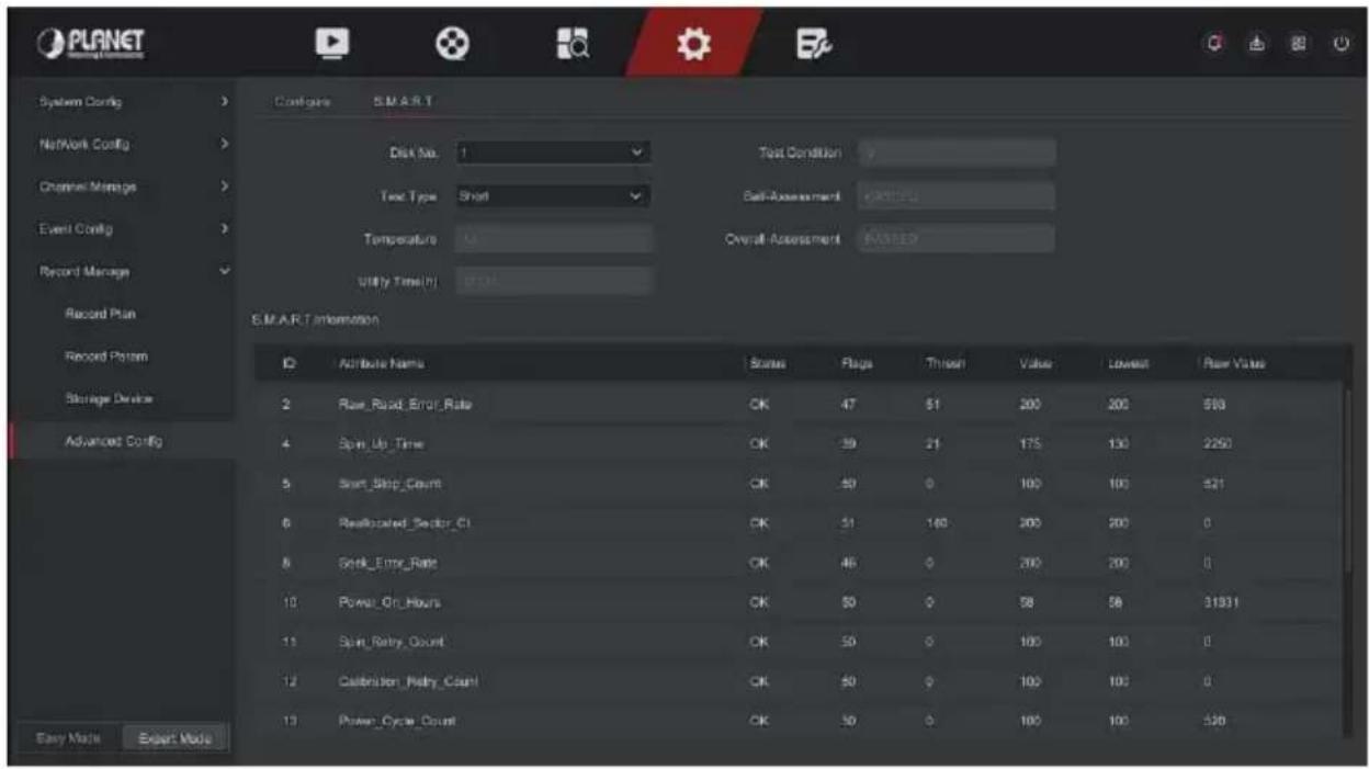
Figure 5-106
Step 2: Select the hard disk to be tested and set "Test Type".
Step 3: The device starts to detect the hard disk.
Step 4: After the hard disk is detected, the hard disk details will be displayed in the S.M.A.R.T. information list.
S.M.A.R.T Configuration:
√ Disk No: Pull down to select the drive number.
√ Test condition: Shows whether the hard disk has been detected.
√ Test type: Short and extended.
√ Temperature: Display hard disk temperature.
√ Utility time(h): Shows how long the hard disk is used (hours).
√ Self-assessment: Show whether the hard disk is passed.
√ Overall-assessment: Show whether the whole hard disk through.
S.M.A.R.T information: Display the hard disk information.
Self test: Click "Self test" to detect the hard disk information.

Note
- Only some devices support hard disk detection. Please refer to the actual situation.
- When the self-assessment or overall evaluation results are "not passed", the hard disk must be replaced to avoid data loss.
- Through the S.M.A.R.T self-test function, the user can use the S.M.A.R.T command to perform a self-test on the hard disk to detect the overall status of the hard disk.
5.7 Maintain
The maintenance interface includes system information, device upgrade, default restoration, automatic maintenance, import and export, and channel information.
5.7.1 System Message
The specific operation steps are as follows:
Step 1: On the main menu page, select "Maintain → System Message" to enter the system information interface, as shown in Figure 5-121 below.
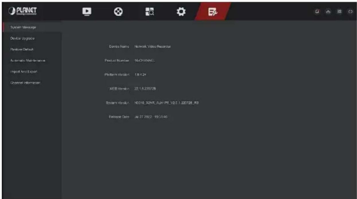
Figure 5-107
Step 2: Check the product model, device version number, system version number and release date of the NVR.
5.7.2 Device Upgrade
■ Manual Upgrade
Insert the USB device with the upgrade file into the NVR to upgrade the version of the NVR. If the device detects the upgrade file in the U disk, the information about the upgrade package (serial number, name, size, date) will be displayed in the list.
The specific operation steps are as follows:
Step 1: Insert the USB device with the upgrade file (named Nxx_xxNR_ALxxxx_V.x.x.x.x_R1.bin) into the NVR.
Step 2: In the main menu, choose "Maintain → Device Upgrade → Manual Upgrade" to enter manual upgrade interface, as shown in Figure 5-108 below.
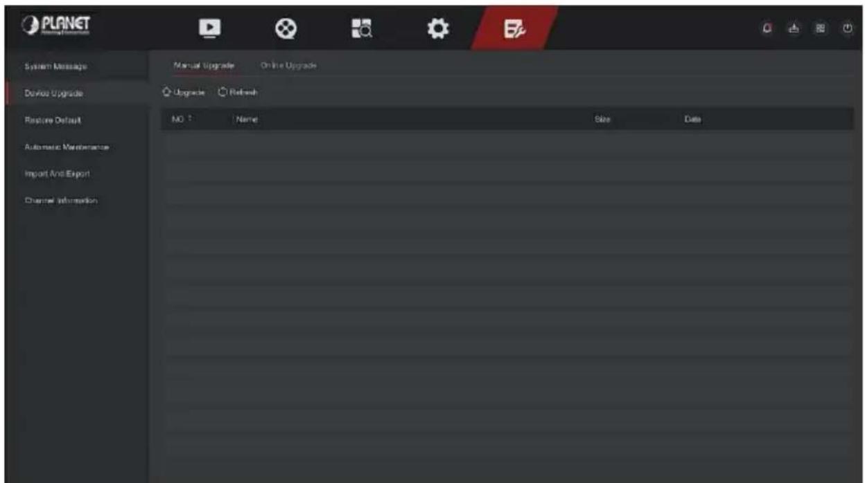
Figure 5-108
Step 3: Click "Refresh", choose the upgrade file, click " Upgrade →
Confirm ", wait for the interface to finish the progress bar, and the device will automatically restart to complete the upgrade.

Note
- After several attempts to refresh, the device still cannot detect the upgrade package. Please check whether the USB disk is in good contact with the USB interface of the device, and the upgrade file name is correct.
- During the upgrade process, do not disconnect the power supply or unplug the USB drive. The system will automatically restart after the upgrade is completed. This process takes about 1-6 minutes. It is recommended to restore the factory settings after the upgrade is completed before using the NVR.
■ Online Upgrade
After the NVR is connected to the public network, the system can be upgraded through an online upgrade. Online upgrade is divided into automatic upgrade and manual detection upgrade, and the current device system version is displayed.
■ Automatic Online Upgrade
The specific operation steps are as follows:
Step 1: In the main menu, choose "Maintain → Device Upgrade → Online Upgrade" to enter automatic online upgrade interface, as shown in Figure 5-109 below.
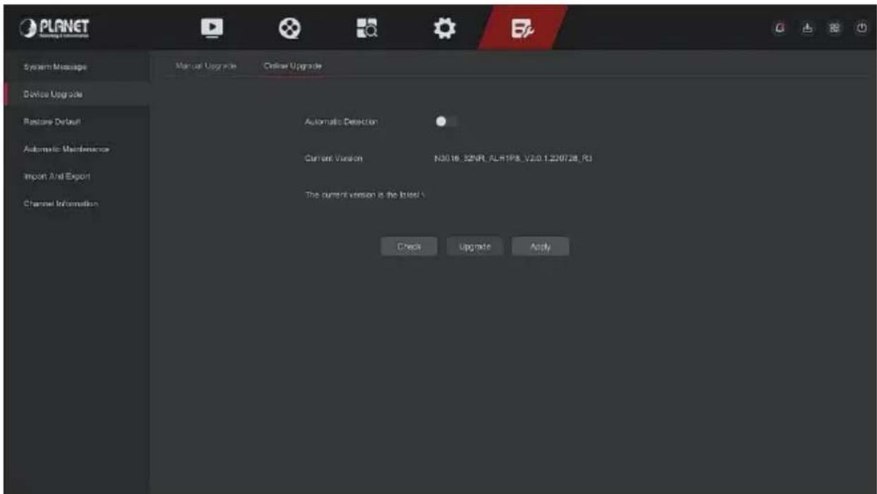
Figure 5-109
Step 2: Enable "Automatic Detection".
Step 3: Click "Apply", when there is a new version in the cloud, the system will automatically detect the version and upgrade the device at the set time.
■ Manual Online Upgrade
The specific operation steps are as follows:
Step 1: In the main menu, choose "Maintain → Device Upgrade → Online Upgrade" to enter online upgrade interface.
Step 2: Click "Check", a prompt interface pops up, if a new version is detected, the system will prompt information about the new version.
Step 3: Click "Update" and wait for the device to download the upgraded file. After the device is upgraded, the device will automatically restart.

Note
- Before testing a new online version, make sure that the NVR is properly connected to the network.
- During the upgrading process, please do not cut off the power or takeoff your U disk. After the upgrading, your system will restart automatically. (This process will take about 1 to 6 minutes.) Here, we advise you to restore factory settings after the upgrading.
When the NVR device runs slowly or the configuration is wrong, you can try to solve the problem by restoring the default.
The specific operation steps are as follows:
Step 1: In the main menu, choose "Maintain → Restore Default" to enter restore default interface, as shown in Figure 5-110 below.
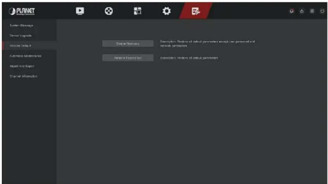
Figure 5-110
Step 2: Choose a recovery type like "Simple Recovery".
Step 3: Click "Apply". Restore all default parameters except user password and network parameters.
Simple Recovery: Restore all default parameters except user password and network parameters.
Restore Factory Set: Restore all default parameters.
5.7.4 Automatic Maintenance
When the device runs for a long time, you can set the device to restart within an idle time to increase the device's running speed.
The specific operation steps are as follows:
Step 1: In the main menu, choose "Maintain → Automatic Maintenance" to enter automatic maintenance interface, as shown in Figure 5-111 below.
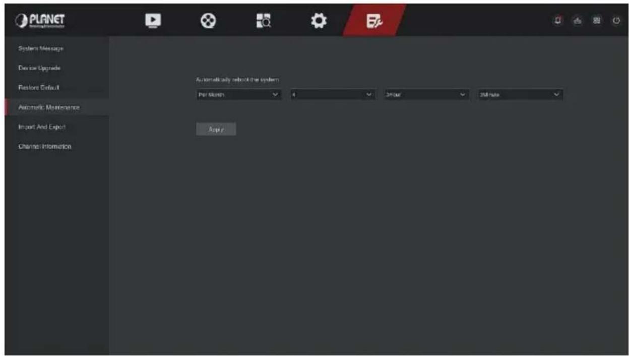
Figure 5-111
Step 2: Select the time for "Automatic Maintenance".
Step 3: Click "Apply" to save the setting.

● Automatic Maintenance the system can be in accordance with the cycle at a fixed time (Every Month, Every Week, and Every Day) set to restart the device, you can also choose "Never", and equipment is not automatically maintained.
5.7.5 Import And Export
If multiple devices need to adopt the same configuration, one device can be configured first, and the configuration file of the device can be "exported" and backed up, and then through the "import" operation, the configuration can be applied to other devices to save more Configure the time.
The specific operation steps are as follows:
Step 1: In the main menu, choose "Maintain → Import And Export" to enter import and export interface, as shown in Figure 5-112 below.
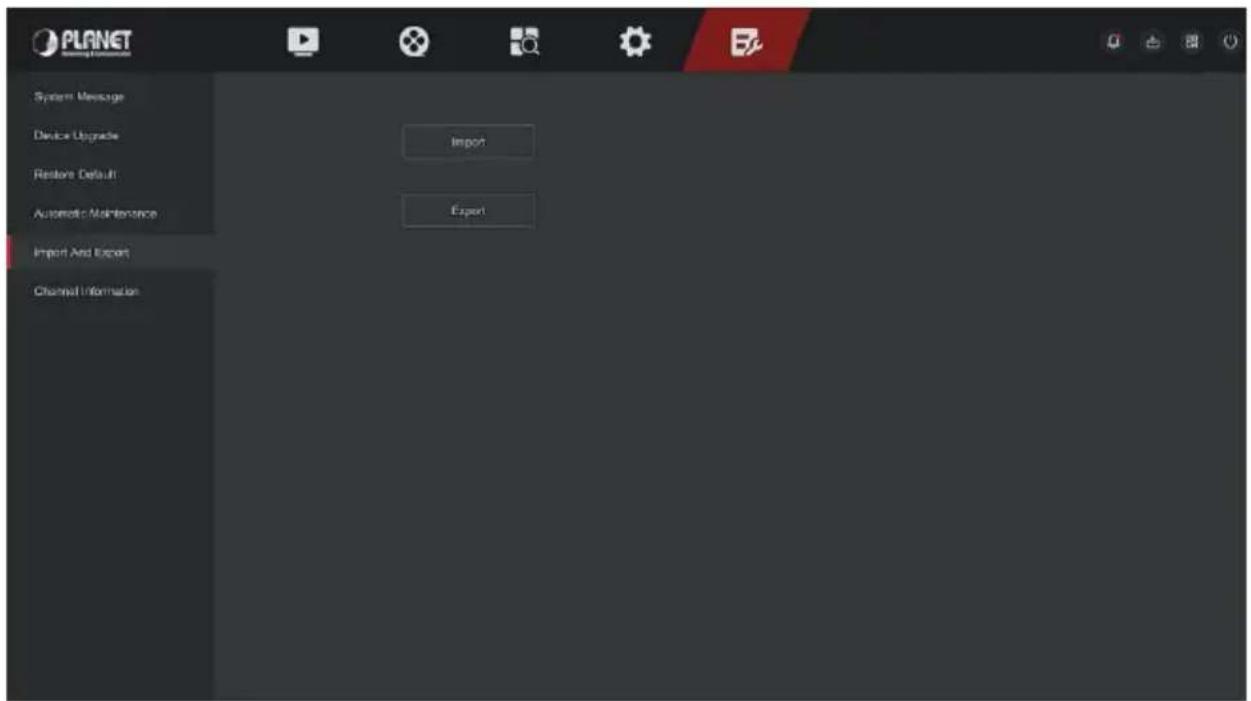
Figure 5-112
Step 2: Export/ import the configuration files.
Config Export: Insert U disk into NVR, click "Export" and wait for the export progress to complete, click "Save".
Config Import: Insert the U disk that stores the configuration file into the NVR, click "Import", after selecting the file, click "Open" to wait for the import process to complete and the device to restart and the configuration file to be imported.
5.7.6 Channel Information
Click "Channel Information" on the maintenance interface to enter the NVR channel information interface, where you can view the resolution of each channel and the IPC version number. As shown in Figure 5-113 below:
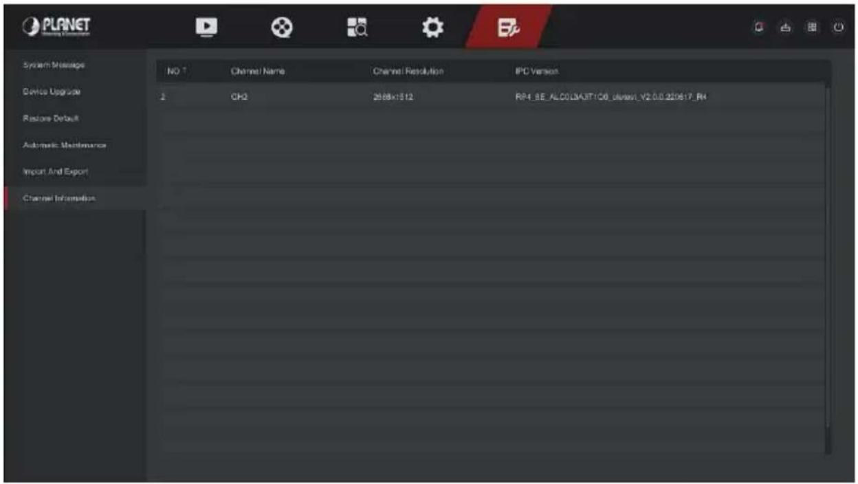
Figure 5-113
Chapter 6 WEB Operation

- The NVR supports accessing and managing devices on the PC through the Web.
- The WEB page provides application modules such as real-time, preview, playback, configuration, and logout.
- The device supports a variety of browser monitoring, such as IE browser, 360 browser, Firefox browser, Google Chrome, Edge browser, Mac Safari (partial).
- Users can access the device's WEB control interface through, multiple PCs at the same time.
6.1 Internet connection
Before using the browser to log in to the web interface, check whether the network between the PC and the NVR is normal.
Step 1: Confirm that the NVR device is properly connected to the network.
Step 2: Set the IP address, subnet mask, and gateway for the PC and NVR devices, respectively.
√ If there is no routing device on the network, allocate the IP address of the same network segment: If there is a routing device on the network, you need to set the corresponding gateway and subnet mask.
√ The default IP address of the NVR device is 192.168.0.20.
Step 3: Check whether the network between the PC and the NVR device is normal. The method is as follows: When the network between the PC and the NVR device is normal, you can log in to the web interface of the NVR through the PC.
√ On the PC, ping***.***.***.*** (NVR IP address) verifies that the network is connected and the returned TTL value is generally equal to 255.
√ Log in to the local interface of the NVR device, and fill in the IP address of the PC on the "Network Test" interface to test whether the network is connected.
6.2 Browser Login
To make sure NVR connects to Internet successfully, open Browser, input required IP address, the default setting is 192.168.0.20, and enter the login interface, as below Figure 6-1.
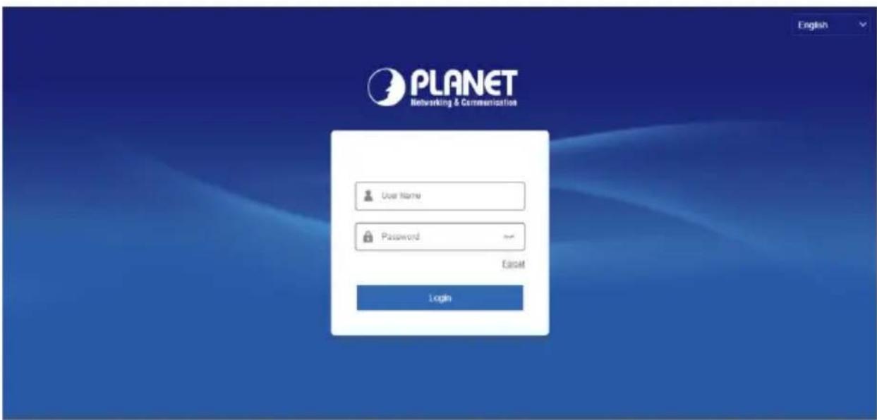
Figure 6-1
Select the system language in the upper right corner of the interface (currently supports Chinese Simplified, Chinese Traditional, English, Polish, Czech, Russian, Thai, Hebrew, Arabic, Bulgarian, German, French, Portuguese, Turkish, Spanish, Italian, Hungarian, Romance, Korean, Dutch, Greek, Vietnamese, and Japanese, Bengali, Persian, Ukrainian,the default is English), enter the user name and password, the default user name is "admin", the password is "admin", click "Login" remote login.

- Modify Password: After logging in to the webpage, the system prompts "The current password is too simple, please modify the password!", click "Modify", enter the new password, confirm the password, set the security question, export the key, click "OK", and complete the password modification.
- Forgot password: On the WEB login interface, click "Forget", select a verification method such as "Answer the question", select the question set when changing the password, enter the corresponding answer, and click "Next" to reset the new password as prompted. Click "Relogin" to return to the login interface.
- If the HTTP port is set to a port other than 80, enter "http://IP address + :( colon) + port number" in the address bar of your browser, such as "http://192.168.1.88:96".
6.3 Active X download, installation
The browser plug-in needs to be downloaded and installed when logging into the device for the first time, as shown in Figure 6-2 below, click "Please click here to download the browser plug-in, please close the browser when the download is finished" and install it, and follow the prompts to complete the installation.
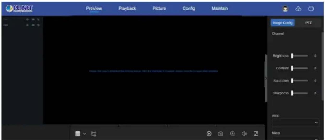
Figure 6-2

- After the NVR upgrades to a new version, you need to delete the original control and download and install the control again.
- For WIN 7 could have problems for backup and recording, if so, please check the Admin setting, procedure as follows:
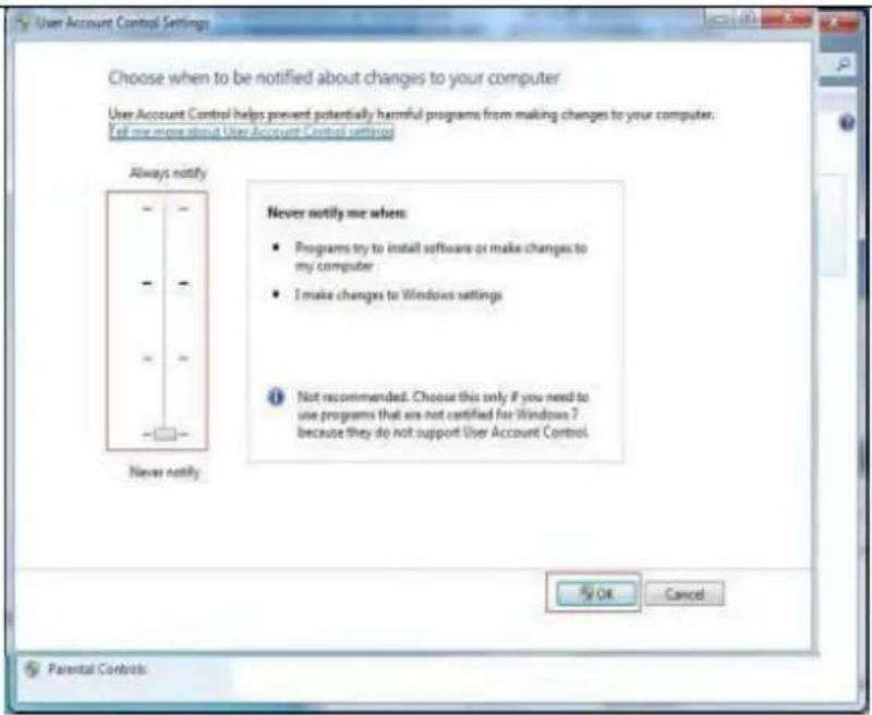
WIN7-1
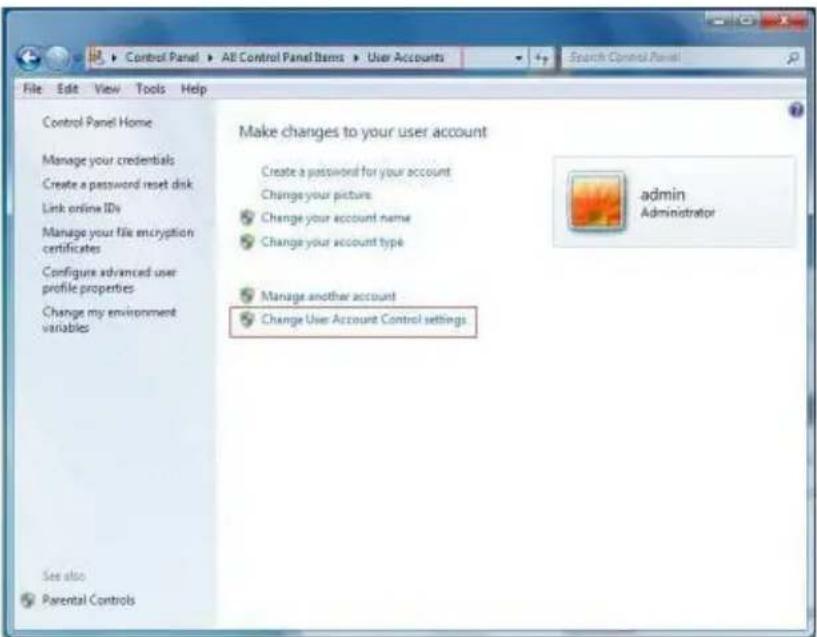
WIN7-2
- The Active X can't be loaded. Please adjust the security level and firewall setting to the lowest, and make some adjustment to Google Chrome as well: Tool-Internet Option- Custom level-ActiveX- enables all the options below ActiveX and click "OK", the Active X will be downloaded and installed automatically, please refer to the Figure 6-3.
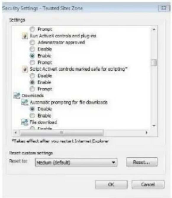
Figure 6-3
6.4 Live View
After login the client successfully, entering live preview interface. The interface as below Figure 6-4:
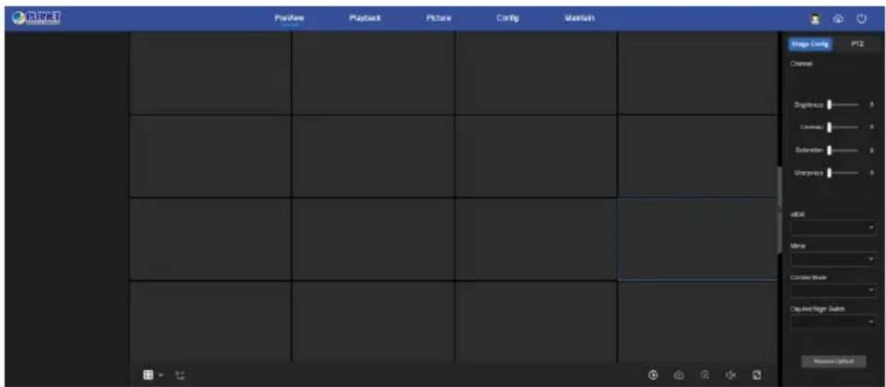
Figure 6-4
1. System Menu. Including Live View, Playback, Picture, Config, Maintain, Help, Logout, and show login user name.
2. Real-time Monitoring Channel. Open/Close Preview, record and streamswitching.
| Mark | Specification |
| CH1-CH16 | Open / close corresponding preview channel. |
 | Start/stop recording, save video on local computer hard drive. |
 | Main and sub bit stream switching |
 | For voice calls, click to automatically connect to the device to make a real-time call.Prerequisites for local device calls: There are audio input/audio output interfaces on the local device, and both mic and speakers have been connected.Note: App and web can't talk to the local device at the same time. |
Table 6-1
- Preview channel shortcut button
| Mark | Specification |
 | Preview window toggle. From left to right are: 1 split screen, 4 split screen, 9 split screen. According to the number of channels supported by the device, the preview window will be different. Please refer to the actual situation. |
 | Switch all preview channel master, sub streams, and open preview |
 | Open / Close all preview channels. |
 | Click this icon to take a picture. The default storage path of the picture is C:\Record. You can enter the Configuration → Local Config interface to modify it. |
| [W3YS] | Click this icon to start recording on all channels; click the icon again to stop recording. The default storage path of the recording is C:\Record. You can enter the Configuration → Local Config interface to modify it. |
 | Local electronic zoom, click this icon to open the electronic zoom function, select to enlarge the channel, hold down the left mouse button to select the area to be zoomed in, release the left button, and select the area to be enlarged; in the zoom channel, click the right mouse button to restore the original status. |
 | 1 Split screen preview, click to switch channels |
 | Turn on / off the speaker. If the audio is not turned on, there is no sound when listening. |
| [85DS] | Full-screen playback, press the keyboard Esc to exit the full screen. |
Table 6-2
-
Image Config: You can select the corresponding channel, set brightness, contrast, saturation, sharpness, enable wide dynamic, mirror, corridor mode, set day and night switching mode and restore default values.
-
PTZ setting operation window
| Mark | Specification |
| PTZ control direction button | |
 | Zoom button |
 | Focus button |
 | Iris control button |
 | The step size is mainly used for speed control. The larger the value, the faster the rotation speed. For example, the rotational speed of step 7 is much larger than the rotational speed of step 1. |
| [WCDE] | Preset point setting |
| [SBKC] | Call presets |
 | Delete settings |
6.5 Playback
In the main interface, click "Playback" to enter the playback interface, as shown in Figure 6-5 below. Here you can view the equipment video, capture, download and other actions, the settings and NVR settings consistent.
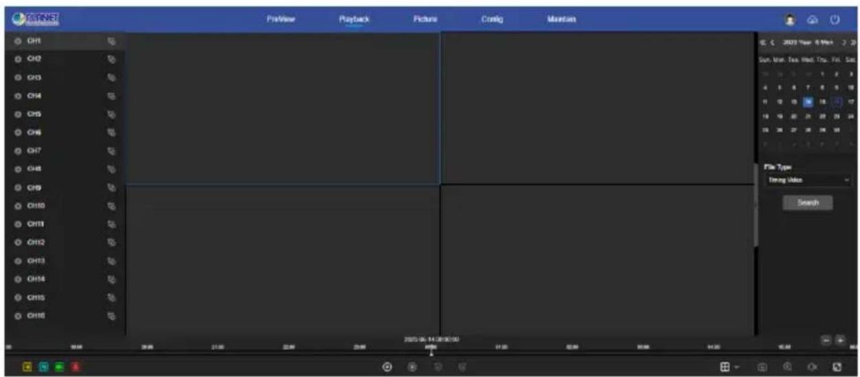
Figure 6-5
Timeline: Displays the type of recording under the current conditions and the time period in which it is located. In the four-picture playback mode, four playback time axes corresponding to the selected four channels can be displayed. In the other single-screen playback modes, only one time axis is displayed. Use the mouse to click a point in the blue area and drag to the yellow line position, that is, playback from that point in time.
Layout: Click " [icon] " to toggle the video playback window.
Play/Pause: After querying the video file, click "播放/播放" to start / pause playback of the searched video.
Stop: When the video is played, press "☐" to stop playing the video.
Slow Forward: When the video is played, click "◀" video will play slowly, the specific speed of choice 1/2, 1/4, 1/8. After switching, you can check the current playback speed in the current status of the upper right corner of the preview interface.
Fast Forward: When the video is played, click "▶" video will be slow to play, the specific speed of choice 2, 4, 8. After switching, you can check the current playback speed in the current status of the upper right corner of the preview interface.
Mute/Open the Sound: When the video is played, click "☐/☐" to turn on / off the sound of the recorded video.
Enable Electronic Zoom: When the video is played, click "⊕/⊕" to turn on / off the electronic zoom function of the recorded video. Turn on the electronic zoom function, hold down the left mouse button, select the position to zoom in on the playback screen, release the mouse, select the location screen is placed, click "⊕", the magnification screen is restored.
Snapshot: When the video is played, click "☐" to capture the settings to the local configuration settings.
clip: When the video is played, click "☐" to start recording, and then click Save Clip File again, which is stored in the local configuration settings.
Download: After querying the video file, click "◀" to enter the video file list, select the download file, click "Download", the video file starts to download in order, stored in the local configuration settings location. The file download interface is shown in Figure 6-6. The "First Page", "Prev Page", "Next Page" and "Last Page" are used to scroll through all video files. You can use "Edit" under "Set date / time manually" to intercept and download the video file.
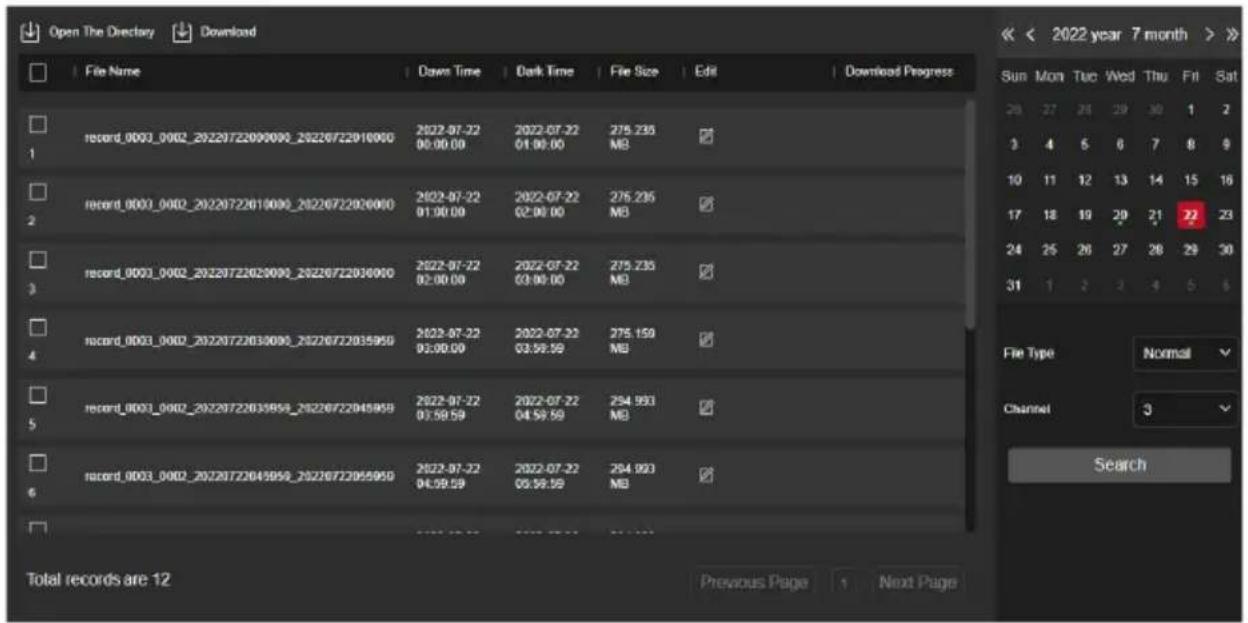
Figure 6-6
Full Screen: When the video is played, click "☐" the full screen playback video. Press "Esc" on the keyboard to exit the full-screen playback interface.
Drag and drop: the video playback, the left mouse button click on the time axis to play the position, drag left and right, drag it to the middle of the yellow time point position, playback channel to play the point in time recording.
6.6 Picture
In the picture interface, you can view and download all the pictures captured on the device side. The steps are as follows:
Step 1: In the main interface, click "Picture" to enter the picture interface, as shown in Figure 6-7 below.
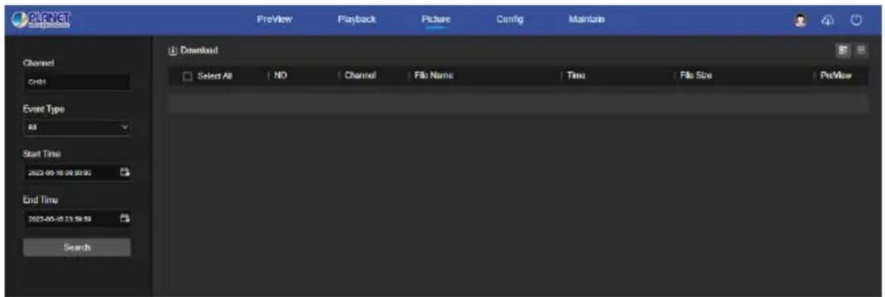
Figure 6-7
Step 2: Select the channel, select the event type, and set the search time range.
Step 3: Click "Search", the searched image is displayed on the right side of the interface, as shown in Figure 6-8 below.
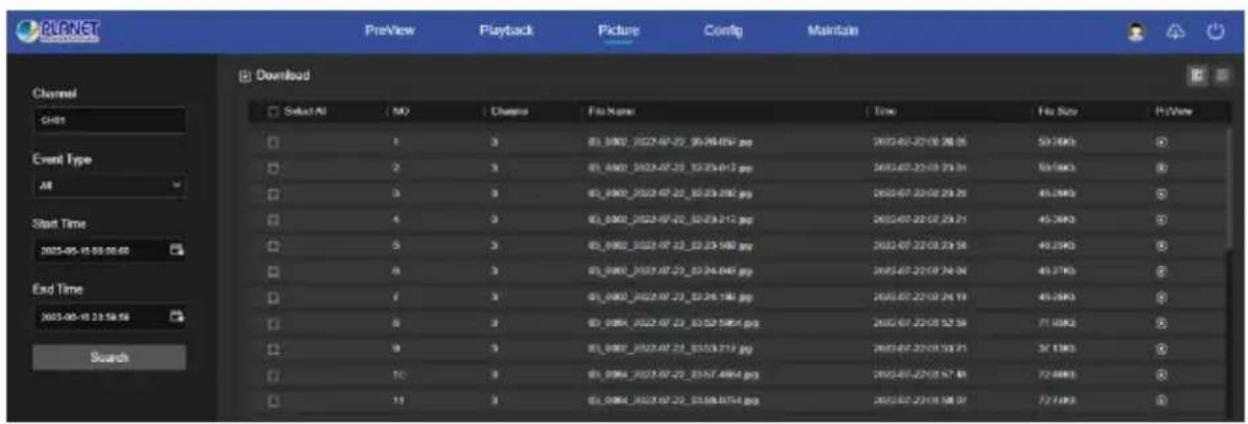
Figure 6-8
Step 4: Select the picture, click "Download" to select the storage path, click "OK", and select the image to download to the specified folder. Click on the "Corresponding to the preview position to view the image."
Channel: Select the channel to which you want to search for image files. You can select one channel individually or multiple channels or "Select All" at the same time.
Event Type: Capture image type, the drop-down box option consists of All, Manual capture, Motion capture, Face detection, Regional Intrusion, Crossover, Wandering and Staff Gathering.
Start/End Time: The time range for capturing image files.
Query: Click "Search", the system will query the corresponding picture file according to the set channel, event type and time range, and display it in the file list.
Details: The image searched by clicking "☐" is displayed in the list as detailed information.
Big icon: The image searched by clicking "☐" is displayed in the list as a large icon, as shown in Figure 6-9 below:
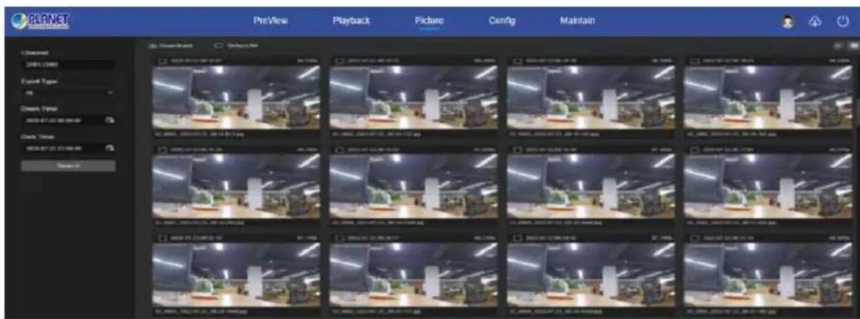
Figure 6-9
Download: Select the picture, click "Download", select the picture to download to the specified folder.
6.7 Config
6.7.1 System Config
6.7.1.1 Local Configuration
In the main interface, click "Config → System Config → Local
Configuration " to enter the local configuration interface, as shown in Figure 6-10 below. Here you can set the device video file, capture and clip corresponding to the local computer's save path, click "Browse" to select the path to save, click "Apply" to complete the path settings.
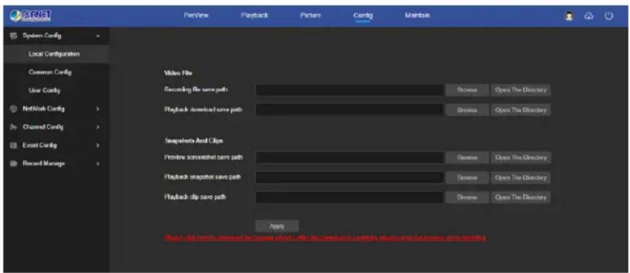
Figure 6-10
6.7.1.2 Common Config
■ Device Settings
In the main interface, click "Config → System Configuration →
Common Config → Device Settings " to enter the device setting interface, as shown in Figure 6-11 below. Here you can set the device language, auto logout time, and device name, click "Apply" to complete the setting.
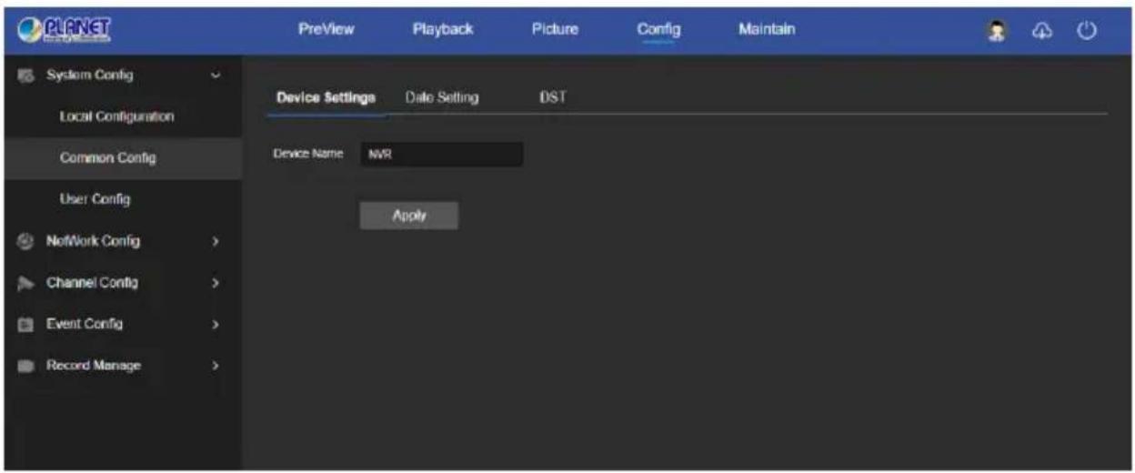
Figure 6-11
■ Date Setting
In the main interface, click "Config → System Configuration → Common Config → Date Setting" to enter the date setting interface, where you can set the device time, as shown in Figure 6-12.
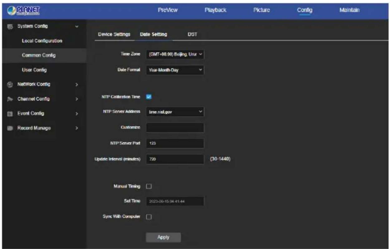
Figure 6-12
【Time Zone】Displays the current device selection time zone.
【Date Format】Select the date format, such as YYYY/MM/DD.
【NTP Calibration Time】The NVR time will synchronization with network, and you can change the different time zones. (This feature requires that NVR network environment can connect to the Internet.) Click on the "Apply" after completing the settings.
【NTP Sever Address】SNTP server address, including "time.windows.com", "time.nist, gov", "time-nw.nist.gov", "timea.nist.gov", "time-b.nist.gov" Optionally.
【Custom】"Custom" enter the NTP server address.
【NTP server port】Enter the custom NTP server port.
【Update interval】The time interval between the NVR and the NTP server is 720 minute by default. You can set "30\~1440".
【Manual Timing】After opening, you can manually set the date and time of the NVR.
【Set Time】Manually set the date and time of the device, click "Apply" after the setting is complete.
【Synchronize with computer time】After selecting, click Apply, the NVR time is synchronized with the time on the currently connected local computer.
■ DST
Daylight saving time (DST) refers to the system of artificially stipulating local time for energy conservation. The unified time used during the implementation of this system is called "DST". In the System Configuration interface, click "DST" to enter the daylight saving time setting interface, where you can enable daylight saving time, set daylight saving time, end time and end time, as shown in Figure 6-13
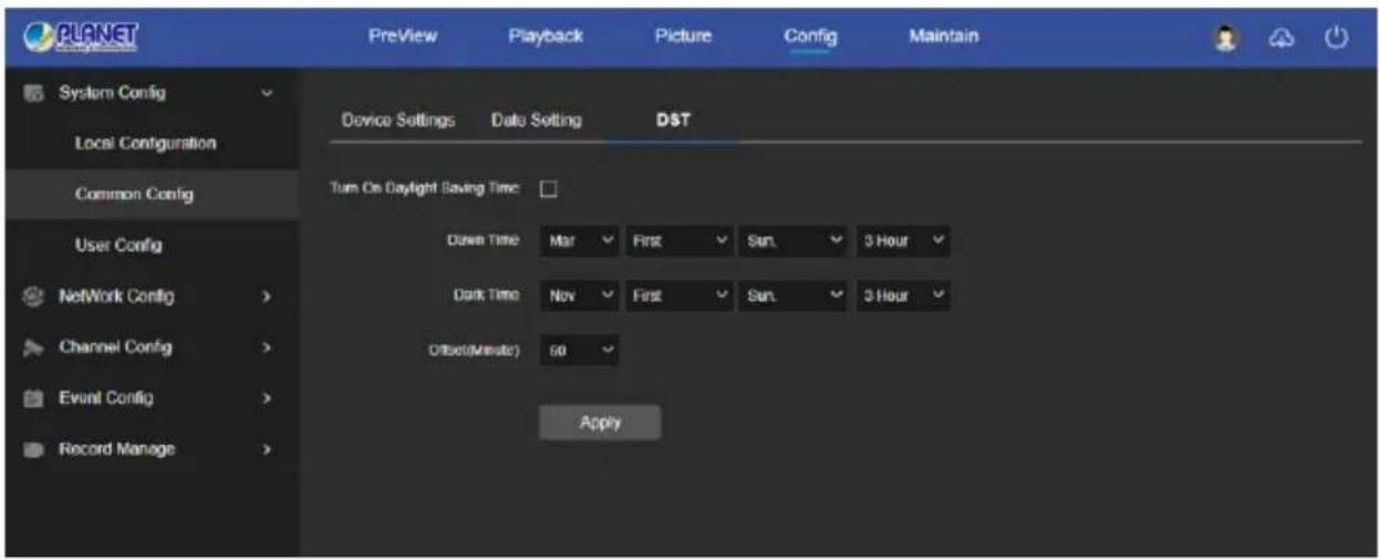
Figure 6-13
6.7.1.3 User Config
In the main interface, click "Config → System Configuration → User Config" to enter the User management interface, as shown in Figure 6-14 below. Here you can add, delete, edit users, user settings are consistent with the local settings of NVR.
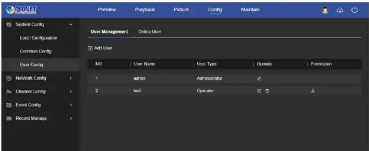
Figure 6-14
6.7.2 Network Config
6.7.2.1 Basic Config
TCP/IP
In the main interface, click "Config → Network Config → Basic Config → TCP/IP" to enter the TCP/IP setting interface, as shown in Figure 6-15 below. Here you can set the IP Address, Network Mask, Gateway, Port, DNS and other network information, the TCP/IP setting is consistent with the NVR local setting.
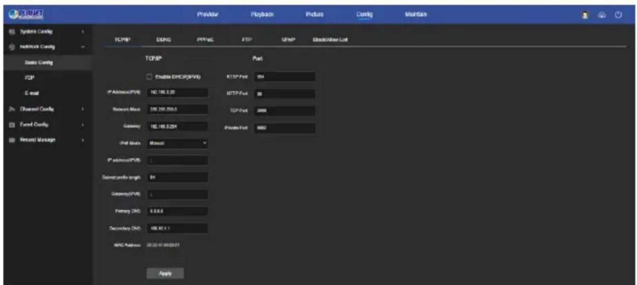
Figure 6-15
■ DDNS
In the main interface, click "Config → Network Config → Basic Config → DDNS" to enter the DDNS setting interface, as shown in Figure 6-16 below. Here you can enable and set the DDNS function, the DDNS setting is consistent with the NVR local setting.
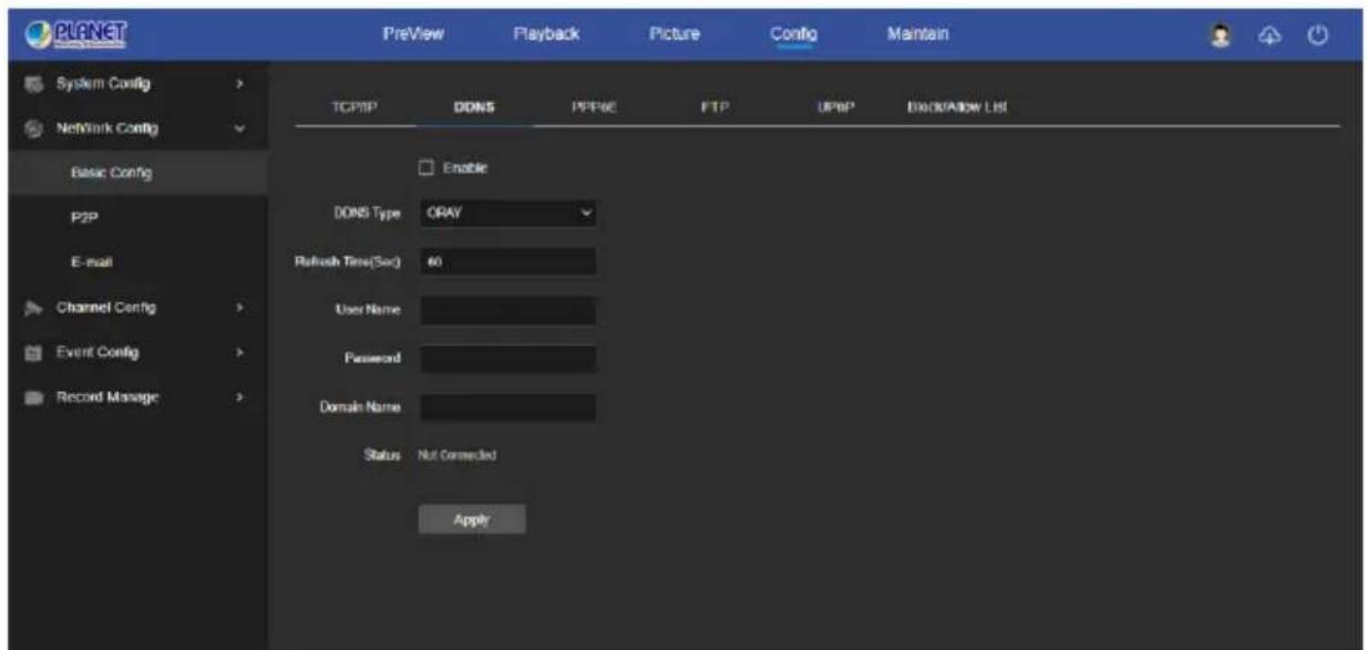
Figure 6-16
■ PPPoE
In the main interface, click "Config → Network Config → Basic Config → PPPoE" to enter the PPPoE setting interface, as shown in Figure 6-17 below. Here you can enable and set the PPPoE function, the PPPoE setting is consistent with the local settings of NVR.
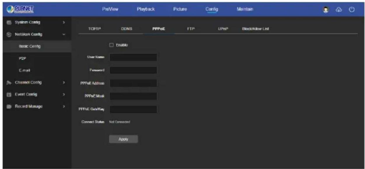
Figure 6-17
FTP
In the main interface, click "Config → Network Config → Basic Config → FTP " to enter the FTP setting interface, as shown in Figure 6-18 below. Here you can enable and set the FTP server function. The FTP settings are the same as the NVR local settings.
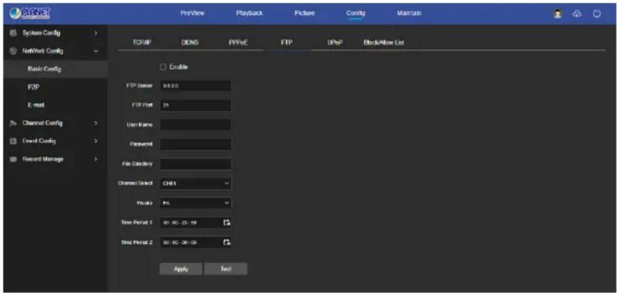
Figure 6-18
■ UPnP
In the main interface, click "Config → Network Config → Basic Config → UPnP" to enter the UPnP setting interface, as shown in Figure 6-19 below. Here you can enable and set the UPnP function, UPnP settings are consistent with the NVR local settings.
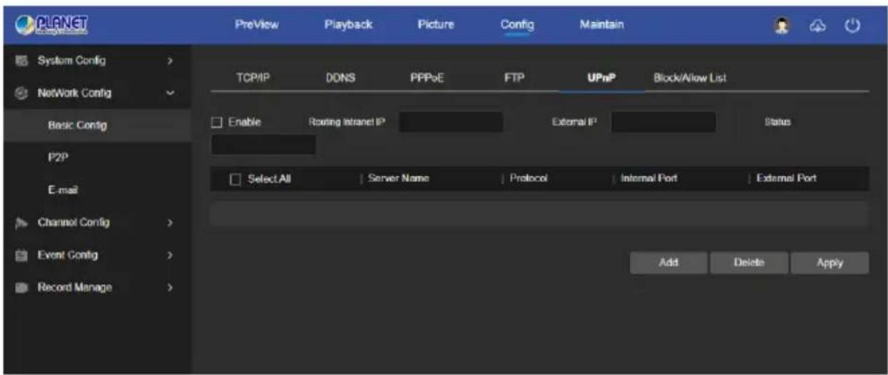
Figure 6-19
■ Block/Allow List
In the main interface, click "Config → Network Config → Basic Config → Block/Allow List" to enter Block/Allow List setting interface, as shown in Figure 6-20 below. Here you can enable and set the Block/Allow List function, Block/Allow List settings are consistent with the NVR local settings.
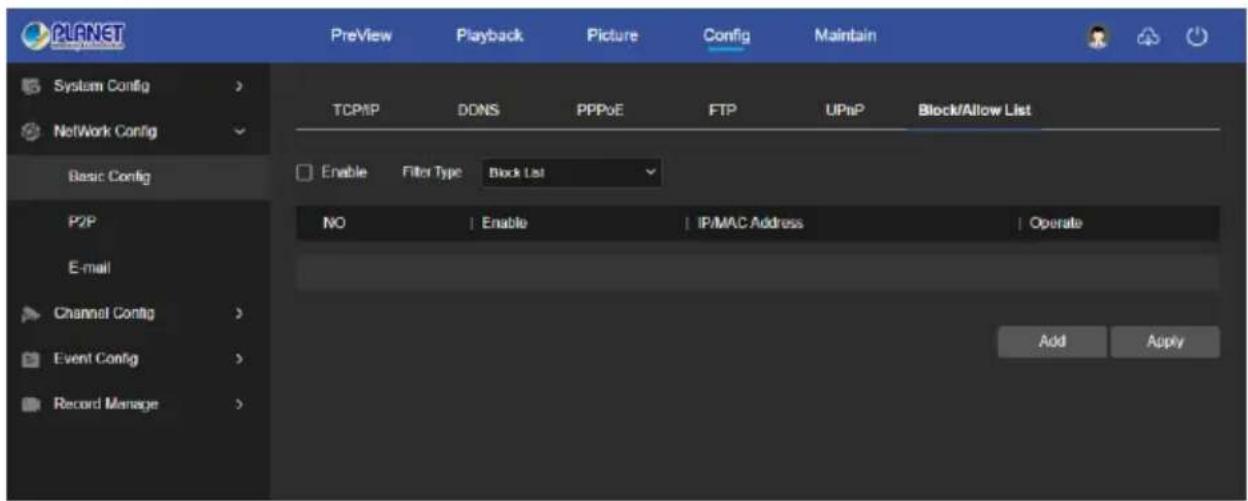
Figure 6-20
6.7.2.2 P2P
P2P
In the main interface, click "Config → System → Network → P2P" to enter the P2P setting interface, as shown in Figure 6-21 below. Here you can enable / disable the P2P function, check the serial number of the device, use the mobile phone to scan the QR code to download the App, and the settings of the P2P are consistent with the local settings of the NVR.
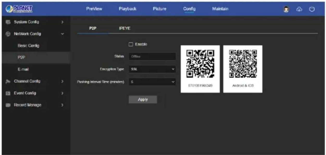
Figure 6-21
IPEYE
Click "Configuration Network Configuration P2P IPEYE " on the main interface to enter the IPEYE setting interface, as shown in Figure 6-22 below, and the settings of the IPEYE are consistent with the local settings of the NVR.
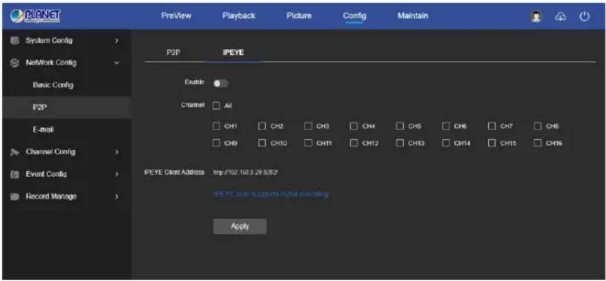
Figure 6-22
6.7.2.3 E-mail
In the main interface, click "Config → System → Network → E-mail" to enter the email setting interface, as shown in Figure 6-23 below. Here you can open and set the mail function. The settings of the E-mail are consistent with the local settings of the NVR.
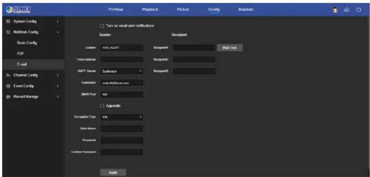
Figure 6-23
6.7.3 Channel Config
6.7.3.1 Channel Config
In the main interface, click "Config → Channel Config → Channel Config" to enter the add camera interface, as shown in Figure 6-24 below. Here you can add, edit, and delete devices to the device as needed. The relevant parameters are consistent with the local settings of the NVR.
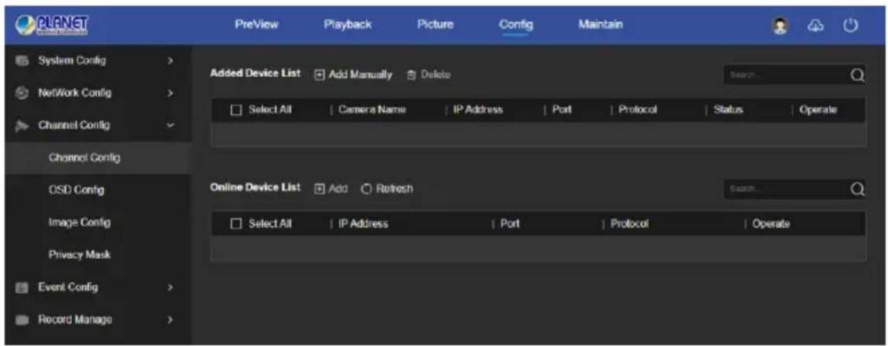
Figure 6-24
6.7.3.2 OSD Config
In the main interface, click "Config → Channel Config → OSD Config" to enter the OSD config interface, as shown in Figure 6-25 below. Here you can view and set the device text, date and other related information, the relevant parameters are consistent the local settings of the NVR.
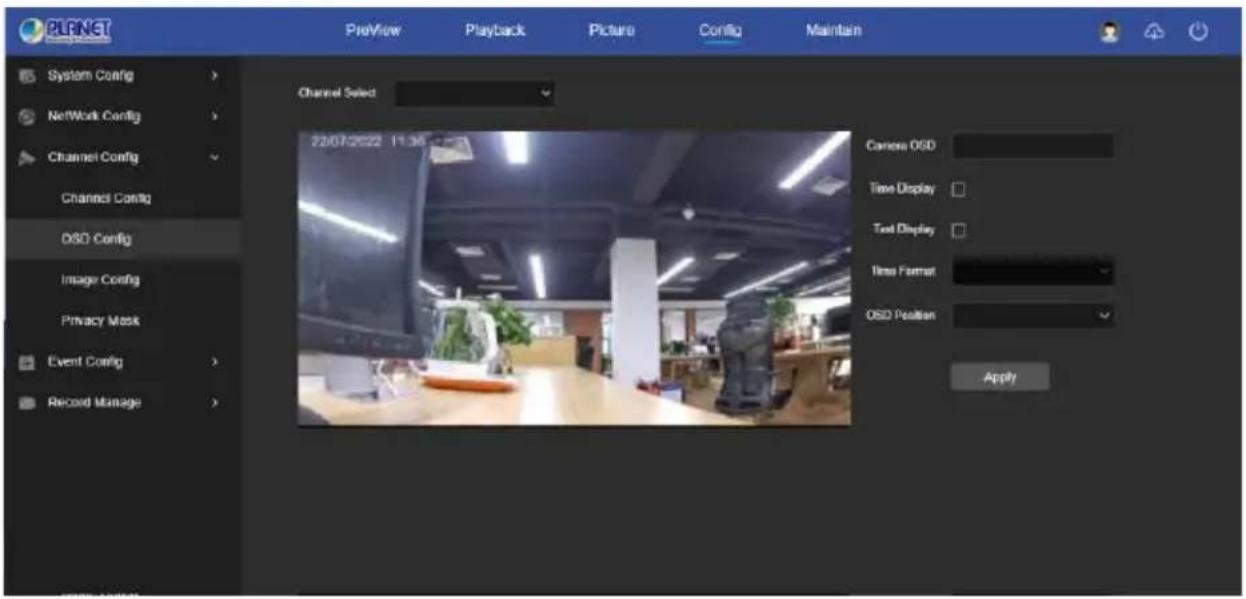
Figure 6-25
6.7.3.3 Image Config
In the main interface, click "Config → Channel Config → Image Config" to enter the Image setting interface, as shown in Figure 6-26 below. Here you can view and set the channel image (brightness, contrast, saturation and sharpness), exposure, day and night mode, white balance, video adjustment, image enhancement and backlight compensation. The relevant parameters are consistent with the local settings of the NVR.
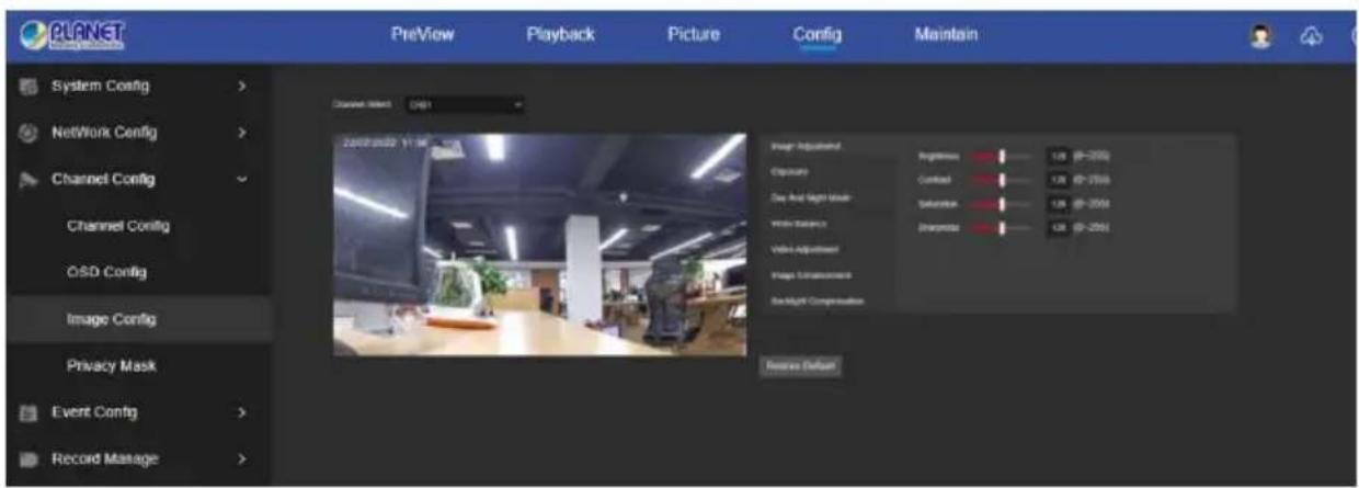
Figure 6-26
6.7.3.4 Privacy Mask
In the main interface, click "Config → Channel Config → Privacy Mask" to enter the privacy mask setting interface, as shown in Figure 6-27 below. Here you can set three shielding areas, and the relevant parameters are consistent with the local settings of the NVR.
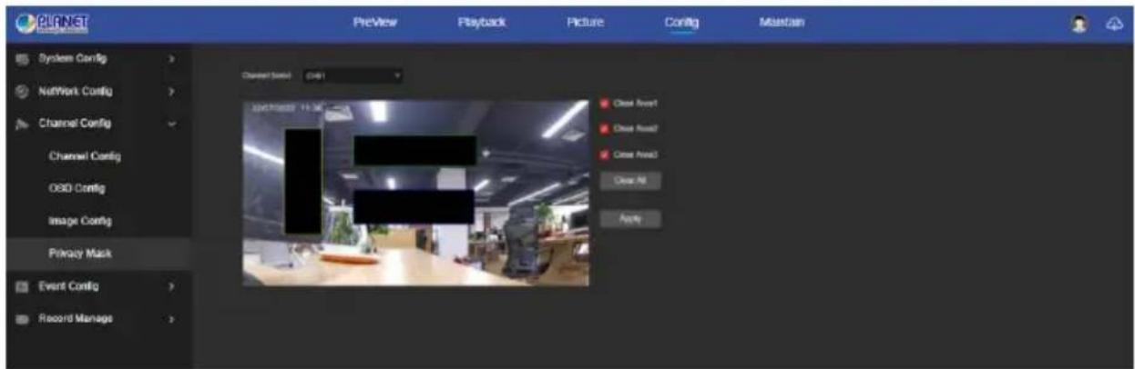
Figure 6-27
6.7.4 Event Config
6.7.4.1 Ordinary Event
■ Motion / Viedo Tampering
In the main interface, click "Config → Event Config → Ordinary Event → Motion / Video Tampering" to enter the motion detection setting interface, as shown in
Figure 6-28 below. Here you can view and set device motion detection or video tampering related information. The relevant parameters are consistent with the local settings of the NVR.
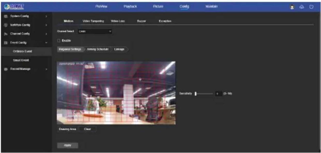
Figure 6-28
■ Video Loss
In the main interface, click " Config → Event Config → Ordinary Event → Video Loss " to enter the video loss setting interface, as shown in Figure 6-29 below. Here you could enable channel video loss and set the corresponding alarm when the video is lost. The relevant parameters are consistent with the local settings of the NVR.
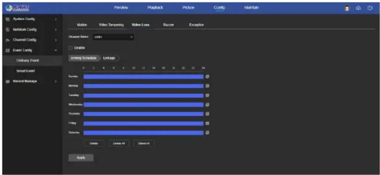
Figure 6-29
■ Buzzer
In the main interface, click "Config → Event Config → Ordinary Event → Buzzer" to enter the buzzer alarm setting interface, as shown in Figure 6-30 below. Here you could set the duration of the buzzer alarm. The related parameters are consistent with the local settings of the NVR.
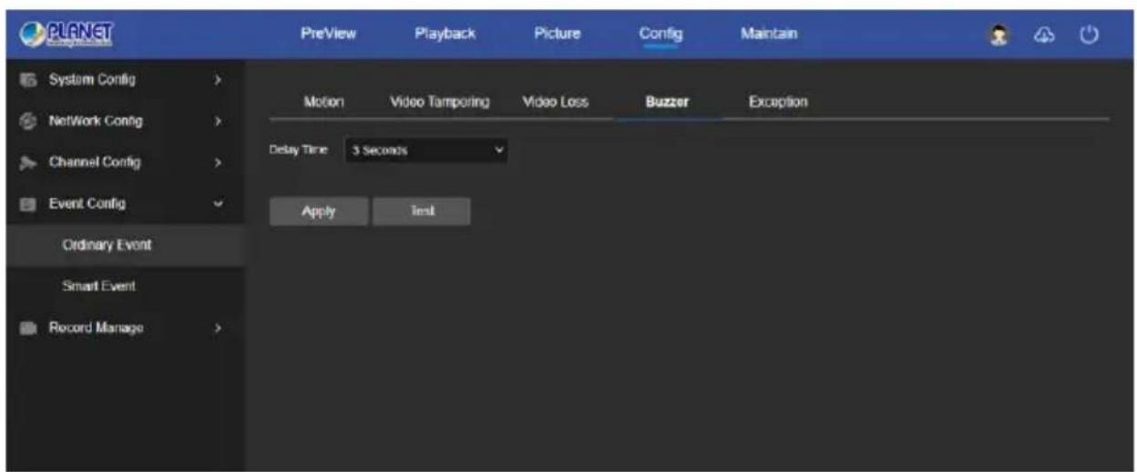
Figure 6-30
■ Exception
In the main interface, click "Config → Event Config → Ordinary Event → Exception" to enter the exception setting interface, as shown in Figure 6-31 below. Here you could set the abnormal alarm (No Disk, Disk Error, Broken Network, IP Conflict). The abnormal alarm is consistent with the local setting of NVR.
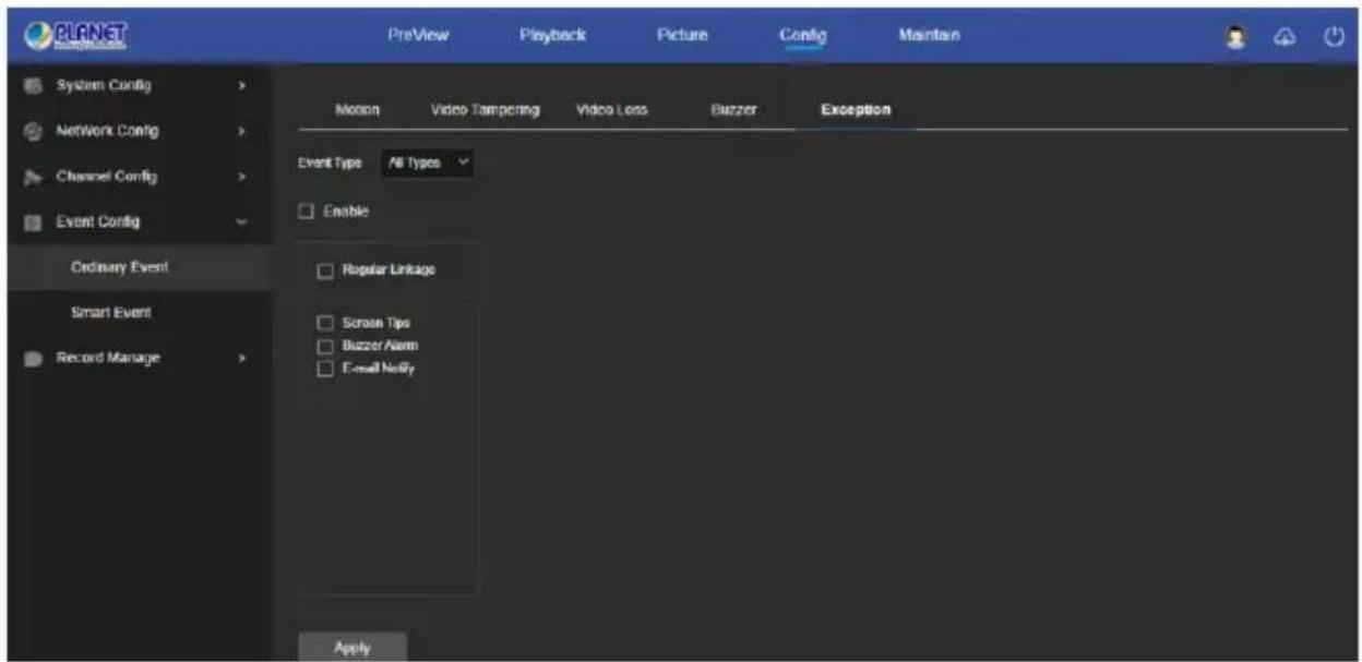
Figure 6-31
6.7.4.2 Smart Event
■ Line Crossing Detection
In the main interface, click "Config → Event Config → Smart Event → Line Crossing Detection" to enter the Crossover detection setting interface, as shown in Figure 6-32 below. Here you could set the alarm for crossover detection. The relevant parameters are consistent with the local settings of the NVR.
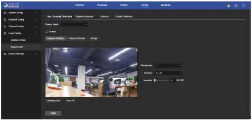
Figure 6-32
■ Regional Intrusion
In the main interface, click "Config → Event Config → Smart Event → Regional Intrusion" to enter the regional intrusion detection setting interface, as shown in Figure 6-33 below. Here you could set the alarm for regional intrusion detection. The relevant parameters are consistent with the local settings of the NVR.
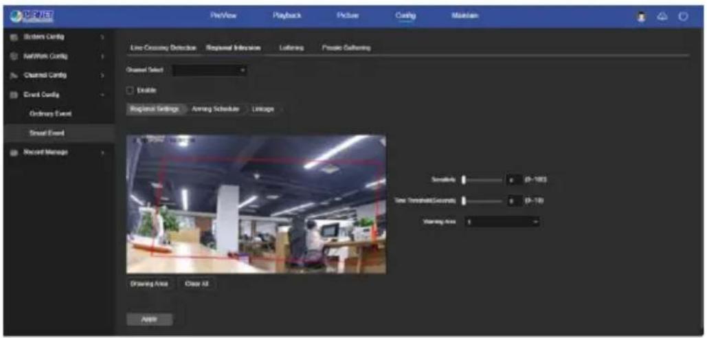
Figure 6-33
■ Loitering
In the main interface, click "Config → Event Config → Smart Event → Loitering" to enter the Wandering detection setting interface, as shown in Figure 6-34 below. Here you could set the alarm for people stay detection. The relevant parameters are consistent with the local settings of the NVR.
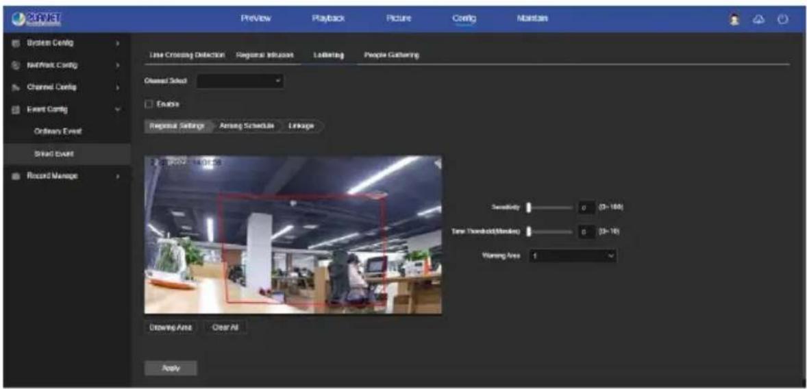
Figure 6-34
■ People Gathering
In the main interface, click "Config → Event Config → Smart Event → People Gathering" to enter the people gathering detection setting interface, as shown in Figure 6-35 below. Here you could set the personnel gathering detection alarm, the relevant parameters are consistent with the local settings of the NVR.
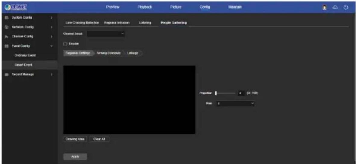
Figure 6-35
6.7.5 Record Manage
6.7.5.1 Record Plan
In the main interface, click "Config → Record Manage → Record Plan" to enter the record plan setting interface, as shown in Figure 6-36 below. The relevant parameters are consistent with the local settings of the NVR.
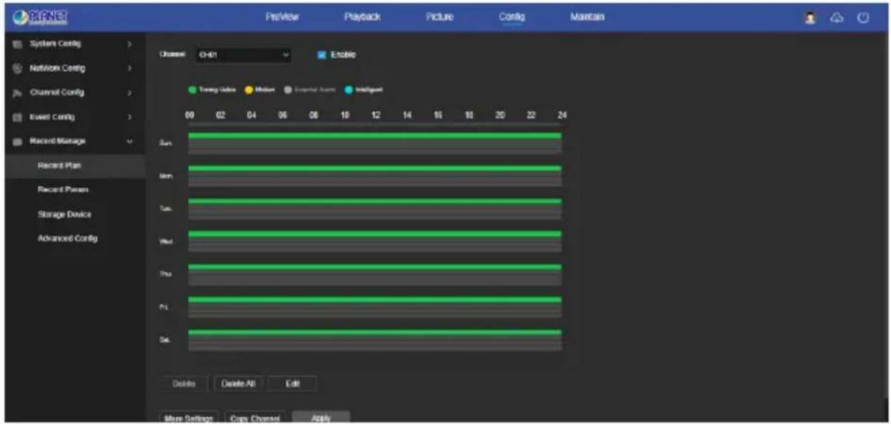
Figure 6-36
6.7.5.2 Record Param
In the main interface, click "Config → Record Manage → Record Param" to enter the record param setting interface, as shown in Figure 6-37 below. The relevant parameters are consistent with the local settings of the NVR.
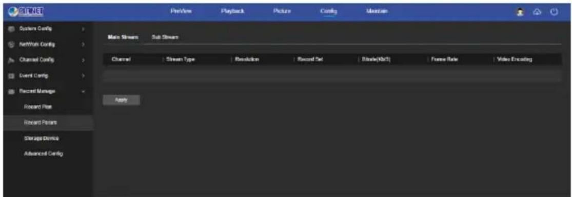
Figure 6-37
6.7.5.3 Storage Device
■ Disk Management
In the main interface, click "Config → Record Manage → Storage Device → Disk Management" to enter the disk management interface, as shown in Figure 6-38 below. Here you can view the HDD information of the connected device and format the hard disk. The operation steps of formatting the hard disk are consistent with the local settings of the NVR.
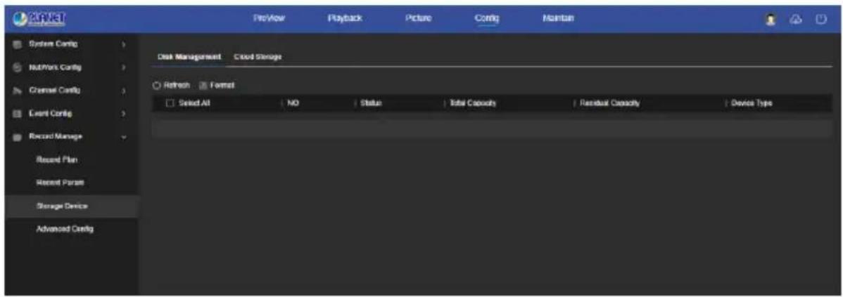
Figure 6-38
■ Cloud Storage
In the main interface, click "Config → Record Manage → Storage Device → Cloud Storage" to enter Cloud Storage setting interface, as shown in Figure 6-39 below. Here you could enable and set the function of Cloud Storage, the specific setting steps are consistent with the NVR local settings.
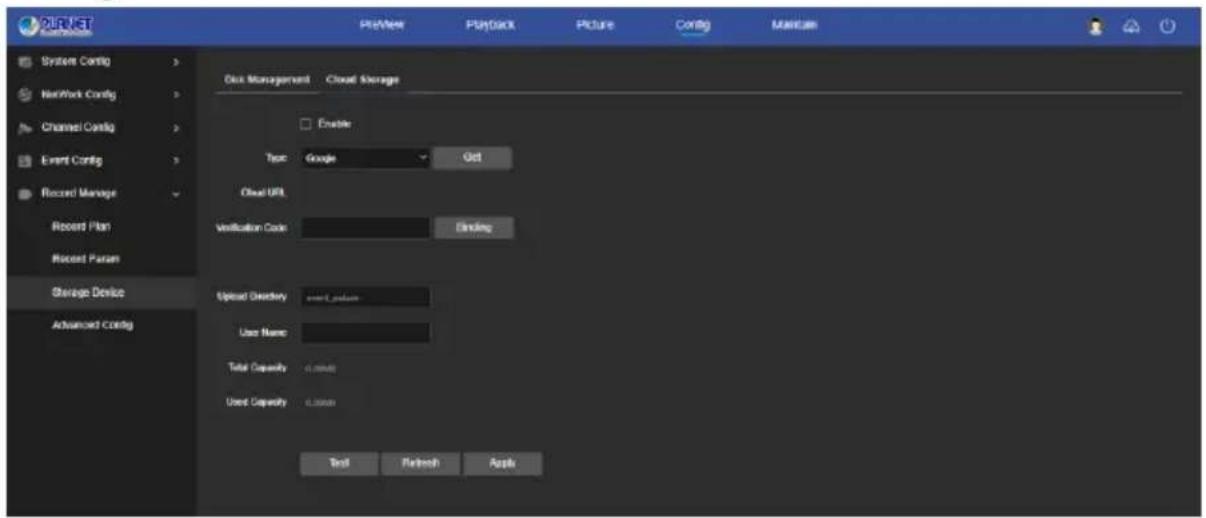
Figure 6-39
6.7.5.4 Advanced Config
■ Config
In the main interface, click "Config → Record Manage → Advanced Config → Config" to enter Config setting interface, as shown in Figure 6-40 below. In the configuration interface, you can view and set related information such as NVR disk full and automatic deletion of recordings, the specific setting steps are consistent with the NVR local settings.
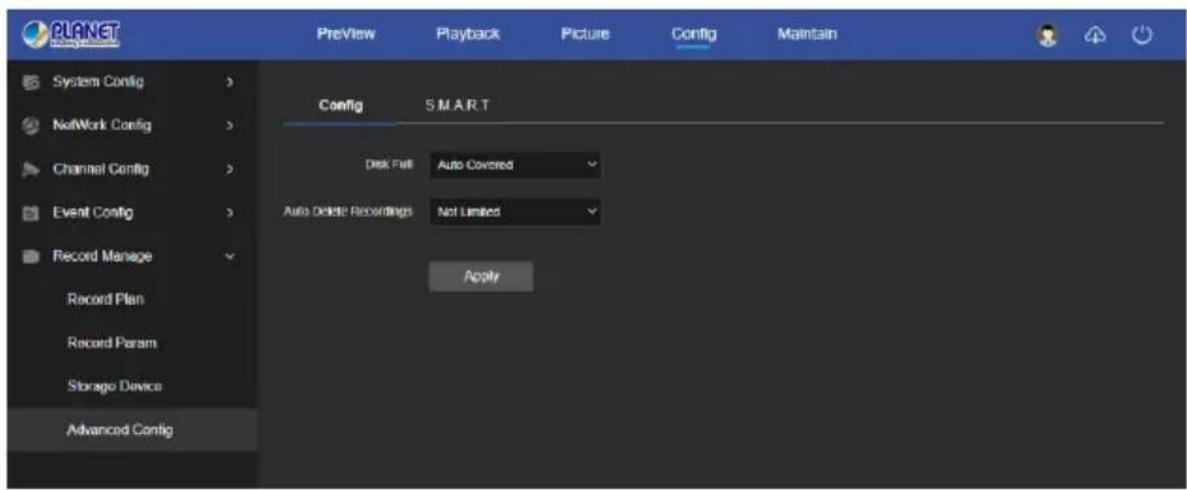
Figure 6-40
■ S.M.A.R.T
In the main interface, click "Config → Record Manage → Advanced Config → S.M.A.R.T" to enter the S.M.A.R.T setting interface, as shown in Figure 6-41 below. The relevant parameters and NVR-side settings consistent.
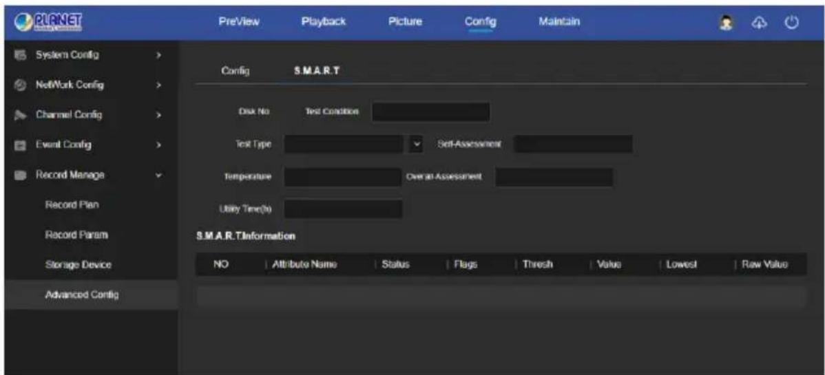
Figure 6-41
6.8 Maintain
6.8.1 System Message
In the System Configuration interface, click "System Message" to enter the device information configuration interface, where you can view the basic information of the current device, as shown in Figure 6-42:
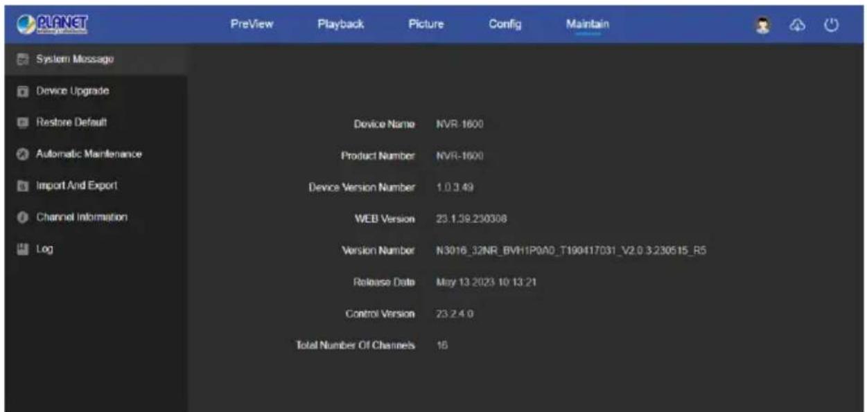
Figure 6-42
【Device Name】The name of the current NVR.
【Product Number】Product model of the current NVR.
【Device Version Number】P2P version number of the current device.
【WEB Version】The current page version of the IPC.
【Version Number】The firmware version of the current NVR.
【Release Date】Release date of the current program.
【Control Version】The LsNXVRPlugin version of the NVR.
【Total Number Of Channels】The total number of channels on the current NVR.
6.8.2 Device Upgrade
In the Maintain interface, click "Device Upgrade" to enter the device upgrade interface, where you can manual upgrade, online upgrade, as shown in Figure 6-43.
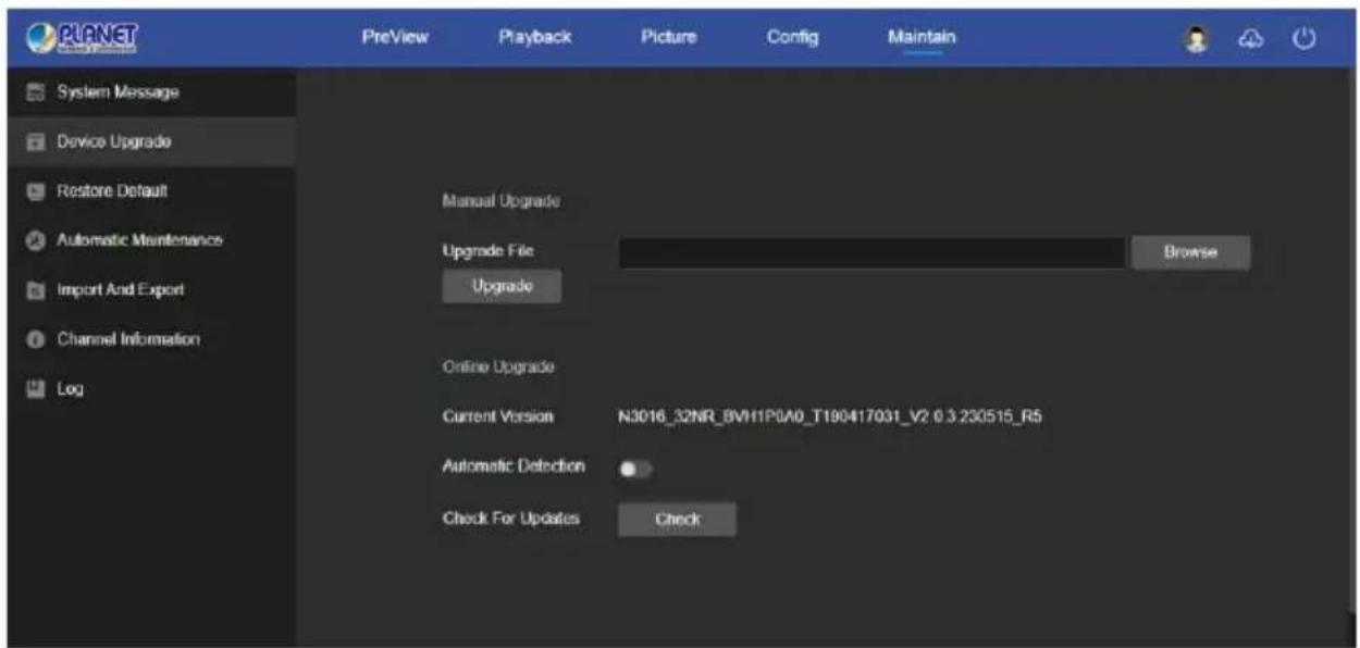
Figure 6-43
【Manual Upgrade】Clicking “Browse” to add upgrade file package, and upgrading the NVR program. (Please careful operation, the error of upgrade file will cause equipment system operate abnormally).
【Online Upgrade】To determine the device connected to the network, check the current version number, click on the "Check", such as the pop-up prompts the latest upgrade version, whether to download, click "OK", the device began to download the upgrade version to complete the automatic upgrade. Click "Cancel" to cancel the upgrade.
【Automatic Detection】To determine the device connected to the network, the device will automatically detect whether there is the latest upgrade version, such as the pop-up prompts the latest upgrade version, whether to download, click "OK", the device began to download the upgrade version to complete the automatic upgrade. Click "Cancel" to cancel the upgrade.
6.8.3 Restore Default
In the maintain interface, click "Restore Default" to enter the device recovery default interface, where you can reset device parameters and reset all the parameters to the factory default, as shown in Figure 6-44.
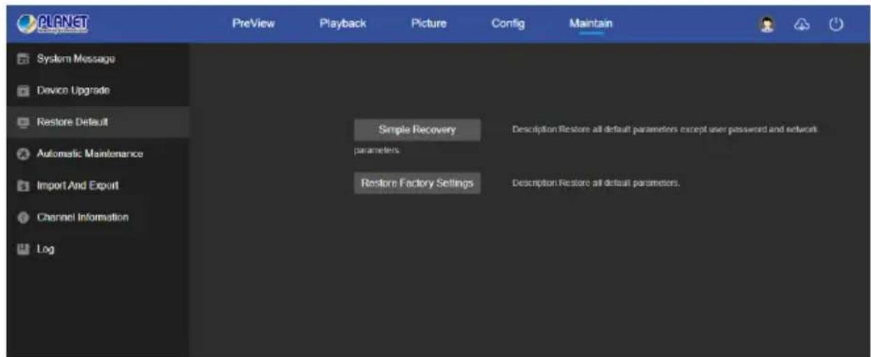
Figure 6-44
【Simple Recovery】Restore all default parameters except user password and network parameters.
【Restore Factory Set】All parameter settings of NVR will be automatically restored to the factory parameter settings (please operate this function carefully).
6.8.4 Automatic Maintenance
In the maintain interface, click "Automatic Maintenance" to enter the scheduled reboot settings interface, where you can set the time for the device to restart, set the restart "cycle" in the drop-down menu, for example, set "3:03 on the 3rd of each month" restart, click "Application", IPC will be at 3 o'clock on the 3rd 3 times a reboot. As shown in Figure 6-45.
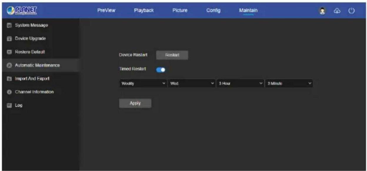
Figure 6-45

- If used the default configuration to restart the device, in order to avoid overloading the server due to excessive device restarts at the same time, the background processing logic of the device is to restart randomly within 1 hour.
6.8.5 Import And Export
In the maintain interface, click "Import And Export" to enter the device parameters import and export interface, where you can export device parameters or import the parameters file to NVR, as shown in Figure 6-46.
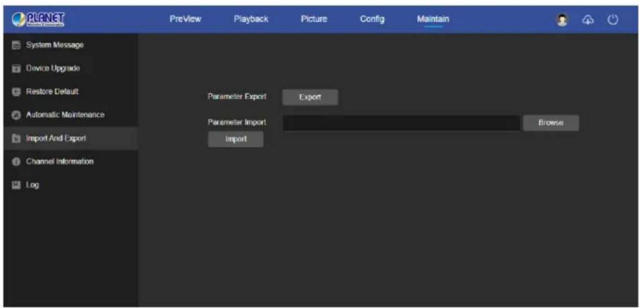
Figure 6-46
6.8.6 Channel Information
In the maintain interface, click "Channel Information" to enter the NVR channel information interface. Here you can view the resolution of each channel and the version number of the IPC, as shown in Figure 6-47.
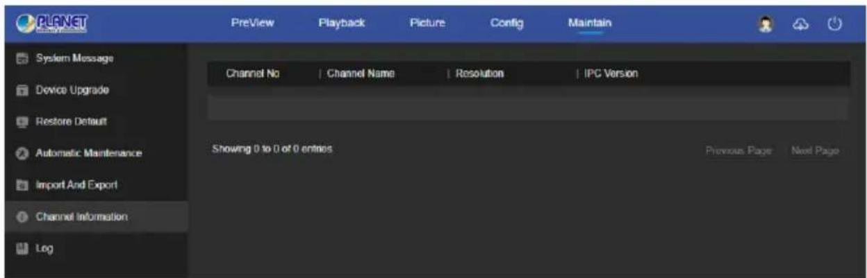
Figure 6-47
6.8.7 Log
In the maintain interface click on the "Log" into the log search interface, where you can query the device alarm and all other relevant information. As shown in Figure 6-48.
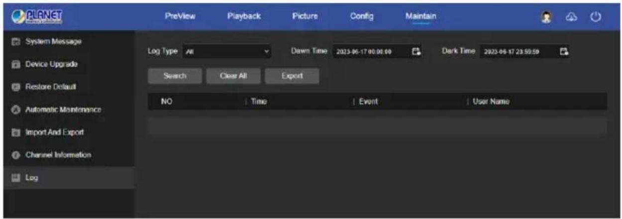
Figure 6-48
【Search】Set the date and start time of the log query, click "Search", the log list shows the IPC execution record that meets the conditions.
【Clear All】Clicking clear button to empty all logging.
【Export】Save the contents of the current log to the location you specified in txt format.
Chapter 7 Appendixes
7.1 Q&A
1. How to do when can't detect the hard disk?
Answer: If the system does not detect the hard disk, kindly please check the data line and the power line of hard disk whether are connected well, whether there is a problem about the interface of hard disk on the motherboard, or kindly please check hard disk whether is supported by the NVR in specification.
2. After modifying password, what can you do when you forget the password?
Answer: When the administrator forget password, kindly please get in touch with our technical staff. The easy to remember and relatively safe password is recommended when you set the password (if you have security needs, kindly please don't try to set simple passwords such as 123).
3. What results will maybe happen due to the heat when NVR is working?
Answer: It will produce some heat when NVR is working, kindly please put the NVR in the place where is safe and ventilated to stop the stability and life of the system be affected due to long-term high temperature of NVR.
4. Whether can use if i install the hard disk drive of computer to NVR?
Answer: If the hard disk you use can be supported by the system of NVR, it can work, but you need note, if the NVR begins to work, all data in your hard disk will loss.
- Whether can playback when recording?
Answer: Yes.
- Whether can remove a part of video recordings of hard disk of NVR?
Answer: Considering the security of document, you can't remove a part of video recording, if you need remove all video recordings, you can format the hard disk.
- Why can't login to NVR client?
Answer: Kindly please check configuration of network connection whether is right, connection of RJ-45 interface whether is fine, if also can't work, kindly please check whether the user name and password are right.
- Why can't find any recording information when playback?
Answer: Kindly please check whether the connection of data line of hard disk is good, whether the time of system is changed, whether the query condition that is not set to save video files. If also have the question after restarting, kindly please check whether the hard disk is damaged.
7.2 Maintenance
- When NVR shutdowns, kindly please don't turn off the power switch directly, should use the shutdown button of system to avoid data loss or damage of the hard disk.
- Ensure NVR away from high temperature heat source and place.
- Remove the dust deposited in the body timing, keep the good ventilation around chassis, it is good for radiating.
- About the audio/video signal line and RS-485 interfaces, kindly please don't hot swap, or these port will be damaged easily.
- Check the HDD power cable and data cable of the NVR regularly and look whether they are aging.
- Avoid the audio/video signal affected by other circuits and devices as much as possible, prevent the hard disk damaged by electrostatic or induced voltage.
- Copyright
- Federal Communication Commission Interference Statement
- FCC Caution
- Federal Communication Commission (FCC) Radiation Exposure
- Statement
- Safety
- CE Mark Warning
- WEEE Regulation
- Energy Saving Note of the Device
- Revision
- Declaration
- Safety Precautions
- CAUTION
- WARNING
- Contents
- Chapter 1 Outlines and Features....13
- Chapter 1 Outlines and Features
- Outlines
- Default
- Descriptive content agreement
- Function Features
- Local monitoring
- ▶ Hard disk management
- ▶ Video Record and Playback
- User Management
- Data backup
- ➢ Alarm and exception management
- Other Local Functions
- Network Function.
- Chapter 2 NVR Appearance
- Front Panel
- Rear Panel
- Mouse Description
- Input Method Introduction
- Chapter 3 Connecting NVR
- Hard Disk Installation
- Installation tools
- Hard disk installation
- Device Connection
- Chapter 4 NVR Startup
- System Initialization
- Boot wizard
- Quick Startup Wizard
- Forget Password
- Preview Interface
- Quick add device
- Quick add device is shown in Figure 4-9:
- Chapter 5 NVR Menu
- Shortcut menu
- Main Menu
- Preview
- Channel shortcut menu
- PTZ
- ■ PTZ Control
- ■ Cruise Control
- Image Configuration
- Playback
- Playback channel video
- ■ Playback
- The specific steps are as follows:
- √ Single channel Playback
- √ Multi-channel playback
- Playback assistance function
- ■ Electronic zoom
- Tag
- ■ Clip
- The specific operation steps are as follows:
- Search
- Video
- Smart
- Picture
- Log
- Config
- Easy Mode
- System Config
- ■ Common Config
- ■ User Config
- ■ Add User
- - Local Config
- - Remote Config
- - Channel Config
- ■ Modify the user
- ■ Delete the user
- ■ Modify the user permission
- ■ Abnormal Config
- Network Config
- ■ Basic Config
- P2P
- ● BitVision App Client operation example
- Step 4: Real-time preview
- Channel Manage
- ■ Channel Config
- ■ Add Device
- Prerequisites:
- ■ OSD Config
- ■ Event Config
- ■ Motion Detection / Video Tampering
- ■ Video Loss
- Record Manage
- ■ Record Plan
- ■ Set the recording plan by drawing method
- Figure 5-42
- ■ Set the recording plan by editing method The specific operation steps are as follows:
- ■ Record Param
- ■ Storage Device
- ■ Disk Management
- Formatting the hard drive
- ■ Cloud Storage
- Expert Mode
- System Config
- ■ Preview Config
- Carousel
- - User Config
- Network Config
- ■ DDNS
- ■ PPPoE
- NTP
- FTP
- ■ UPnP
- ■ Block/Allow List
- ▶ Blocklist:
- Allowlist:
- Add Blocklist / Allowlist operation steps are shown as below:
- BitVision App Client operation example
- IPEYE
- Channel Manage
- ■ Image Config
- ■ Privacy Mask
- Event Config
- ■ Ordinary Event
- Step 6: Click "Apply" to save the setting.
- ■ Exception
- ■ Regional Intrusion
- ■ Loitering
- ■ People Gathering
- Record Manage
- Record Plan
- Figure 5-103
- ■ Advanced Config
- - Configure
- ■ S.M.A.R.T
- S.M.A.R.T Configuration:
- Maintain
- System Message
- Device Upgrade
- ■ Manual Upgrade
- Step 3: Click "Refresh", choose the upgrade file, click " Upgrade →
- ■ Online Upgrade
- ■ Automatic Online Upgrade
- ■ Manual Online Upgrade
- Automatic Maintenance
- Import And Export
- Channel Information
- Chapter 6 WEB Operation
- Internet connection
- Browser Login
- Active X download, installation
- Not recommended. Choose this only if you need to use programs that are not certified for Windows 7 because they do not support User Account Control.
- Live View
- Playback
- Picture
- Config
- System Config
- Local Configuration
- Common Config
- ■ Device Settings
- ■ Date Setting
- ■ DST
- User Config
- Network Config
- Basic Config
- TCP/IP
- P2P
- Channel Config
- Channel Config
- OSD Config
- Image Config
- Privacy Mask
- Event Config
- Ordinary Event
- ■ Motion / Viedo Tampering
- ■ Buzzer
- Smart Event
- ■ Line Crossing Detection
- Record Manage
- Record Plan
- Record Param
- Storage Device
- Advanced Config
- ■ Config
- Maintain
- System Message
- Device Upgrade
- Restore Default
- Automatic Maintenance
- Import And Export
- Channel Information
- Log
- Chapter 7 Appendixes
- Q&A
- How to do when can't detect the hard disk?
- After modifying password, what can you do when you forget the password?
- What results will maybe happen due to the heat when NVR is working?
- Whether can use if i install the hard disk drive of computer to NVR?
- Maintenance
Brand : Planet
Model : NVR-1600
Category : Video recorder