NVR-E6480 - Video recorder Planet - Free user manual and instructions
Find the device manual for free NVR-E6480 Planet in PDF.


| Product Type | 64-Channel Windows-based Network Video Recorder (NVR) |
| Dimensions (W x D x H) | 482 x 560 x 88 mm (2U rack-mount) |
| Weight | 11.4 kg (with 1 system HDD and front cover) |
| Power Input | 100-240V AC, 4-2A, 50-60Hz |
| Power Consumption | 200W |
| Processor | Intel Processor |
| RAM | 2GB |
| Operating System | Windows 7 Standard Embedded |
| Network Interfaces | 2 x RJ45 10/100/1000BASE-T |
| USB Ports | 6 x USB 2.0 |
| Video Output | VGA |
| Audio Interfaces | Mic-in, line-in, line-out |
| Storage Bays | 8 x 3.5" SATA II |
| Max HDD Capacity | Up to 6TB per HDD (total 48TB) |
| RAID Support | RAID 0/1 |
| Max IP Cameras | 64 channels |
| Video Compression | H.264, MPEG-4, M-JPEG |
| Max Resolution | 10 megapixels |
| Recording Bandwidth | 300Mbps total |
| Max Recording Frame Rate | 1920fps total, 30fps per camera |
| Live View Layouts | Local: 1/4/5/6/8/9/10/12/16; Remote: up to 64 |
| Remote Access | Web browser (IE), CMS software, mobile app (CV7-VA, CV7-LP) |
| Event Management | Motion detection, video loss, DI, PIR, disk full, etc. |
| Included Accessories | Power cord, quick installation guide, universal converter, front cover, HDD tray keys, screws |
Frequently Asked Questions - NVR-E6480 Planet
User questions about NVR-E6480 Planet
0 question about this device. Answer the ones you know or ask your own.
Ask a new question about this device
Download the instructions for your Video recorder in PDF format for free! Find your manual NVR-E6480 - Planet and take your electronic device back in hand. On this page are published all the documents necessary for the use of your device. NVR-E6480 by Planet.
USER MANUAL NVR-E6480 Planet
natural_image
Front view of a black DAVI server rack with ventilation slots and drive bays (no visible text or labels)64-Channel Windows-based Network Video Recorder
NVR-E6480

natural_image
Group of business professionals in a meeting around a laptop, engaged in discussion (no visible text or symbols)Copyright
Copyright © 2016 by PLANET Technology Corp. All rights reserved. No part of this publication may be reproduced, transmitted, transcribed, stored in a retrieval system, or translated into any language or computer language, in any form or by any means, electronic, mechanical, magnetic, optical, chemical, manual or otherwise, without the prior written permission of PLANET.
PLANET makes no representations or warranties, either expressed or implied, with respect to the contents hereof and specifically disclaims any warranties, merchantability or fitness for any particular purpose. Any software described in this manual is sold or licensed "as is". Should the programs prove defective following their purchase, the buyer (and not PLANET, its distributor, or its dealer) assumes the entire cost of all necessary servicing, repair, and any incidental or consequential damages resulting from any defect in the software. Further, PLANET reserves the right to revise this publication and to make changes from time to time in the contents hereof without obligation to notify any person of such revision or changes.
All brand and product names mentioned in this manual are trademarks and/or registered trademarks of their respective holders.
Federal Communication Commission Interference Statement
This equipment has been tested and found to comply with the limits for a Class B digital device, pursuant to Part 15 of FCC Rules. These limits are designed to provide reasonable protection against harmful interference in a residential installation. This equipment generates, uses, and can radiate radio frequency energy and, if not installed and used in accordance with the instructions, may cause harmful interference to radio communications. However, there is no guarantee that interference will not occur in a particular installation. If this equipment does cause harmful interference to radio or television reception, which can be determined by turning the equipment off and on, the user is encouraged to try to correct the interference by one or more of the following measures:
- Reorient or relocate the receiving antenna.
- Increase the separation between the equipment and receiver.
- Connect the equipment into an outlet on a circuit different from that to which the receiver is connected.
- Consult the dealer or an experienced radio technician for help.
FCC Caution
To assure continued compliance, use only shielded interface cables when connecting to computer or peripheral devices. Any changes or modifications not expressly approved by the party responsible for compliance could void the user's authority to operate the equipment. This device complies with Part 15 of the FCC Rules. Operation is subject to the following two conditions: (1) This device may not cause harmful interference, and (2) this device must accept any interference received, including interference that may cause undesired operation.
Federal Communication Commission (FCC) Radiation Exposure Statement
This equipment complies with FCC radiation exposure set forth for an uncontrolled environment. In order to avoid the possibility of exceeding the FCC radio frequency exposure limits, human proximity to the antenna shall not be less than 20 cm (8 inches) during normal operation.
Safety
This equipment is designed with the utmost care for the safety of those who install and use it. However, special attention must be paid to the dangers of electric shock and static electricity when working with electrical equipment. All guidelines of this and of the computer manufacture must therefore be allowed at all times to ensure the safe use of the equipment.
CE Mark Warning
This is a Class B product. In a domestic environment, this product may cause radio interference, in which case the user may be required to take adequate measures.
WEEE Regulation

To avoid the potential effects on the environment and human health as a result of the presence of hazardous substances in electrical and electronic equipment, end users of electrical and electronic equipment should understand the meaning of the crossed-out wheeled bin symbol. Do not dispose of WEEE as unsorted municipal waste and have to collect such WEEE separately.
Energy Saving Note of the Device
This power required device does not support Stand by mode operation.
For energy saving, please remove the AC-plug to disconnect the device from the power circuit.
Without remove the AC-plug or switch off the device, the devices will still consuming power from the power circuit. In the view of Saving the Energy and reduce the unnecessary power consuming, it is strongly suggested to switch off or remove the DC-plug for the device if this device is not intended to be active.
Revision
User's Manual of PLANET 64-ch Network Video Recorder
Model: NVR-E6480
Rev: 1.0 (May, 2016)
Part No. EM-NVR-E6480_v1.0
Table of Contents
CHAPTER 1. PRODUCT DESCRIPTION ......6
1.1 PRODUCT FEATURES 9
1.2 REMOTE ACCESS....10
1.3 PACKET CONTENTS....10
1.4 PRODUCT SPECIFICATIONS.... 11
1.5 PHYSICAL SPECIFICATIONS....14
CHAPTER 2. HARDWARE INSTALLATION....15
2.1 RACK MOUNTING 18
2.2 START UP....18
CHAPTER 3. LOG IN TO THE SYSTEM....20
3.1 ACCESS VIA INTERNET EXPLORER BROWSER....20
3.2 ACCESS VIA NVR-E6480 WORKSTATION....23
3.3 CHANGE USER PROFILE....25
CHAPTER 4. NVR USER INTERFACE OVERVIEW....26
4.1 NVR RESIDENT TOOL BARS....26
4.2 NVR MAIN SCREEN 29
CHAPTER 5. LIVE VIEW....31
5.1 SELECT A VIEW....32
5.2 SELECT A CAMERA....33
5.3 CAMERA LIST....34
5.4 REMOVE A CHANNEL 35
5.5 REMOVE ALL CHANNELS 36
5.6 ADD BOOKMARK 37
5.7 ENABLE VIEW PATROL 39
CHAPTER 6. MONITOR THE SYSTEM....41
6.1 READ SYSTEM ALERTS AND CHANNEL STATUS....41
6.1.1 Channel Status....41
6.1.2 Event Panel 43
6.1.3 Instant Event Playback....44
6.1.4 Pop-up Event Playback....45
6.1.5 Hotspot Window 45
6.1.6 Motion Region Indicator 46
6.2 LIVE VIEW OPERATIONS 46
6.2.1 Show Mini Live View Windows on a Map 47
6.2.2 Adjust Audio-in Volume....47
6.2.3 Send Audio Signal....49
6.2.4 Trigger Digital-out Device....49
6.2.5 Watch Instant Playback of a Channel....51
6.2.6 Manual Recording....51
6.2.7 Take a Snapshot of Live Image 52
6.2.8 Digital PTZ Operation....53
6.2.9 Optical PTZ Operation 53
6.2.10 Navigate a Fisheye Camera Channel....55
APPENDIX A: DEFAULT SETTING....76
APPENDIX B: NVR PERFORMANCE....77
ption Chapter 1. Product De
PLANET NVR-E6480, a high-definition IP surveillance solution, is designed to work with PLANET E-series cameras or ONVIF cameras for traffic surveillance, public and other security monitoring applications. The NVR-E6480 is the Windows-based 64-channel NVR that can connect up to 64 IP cameras and supports 8 hard disks. The unit employs RAID 0/1 to optimize the process of securing data easily and quickly.
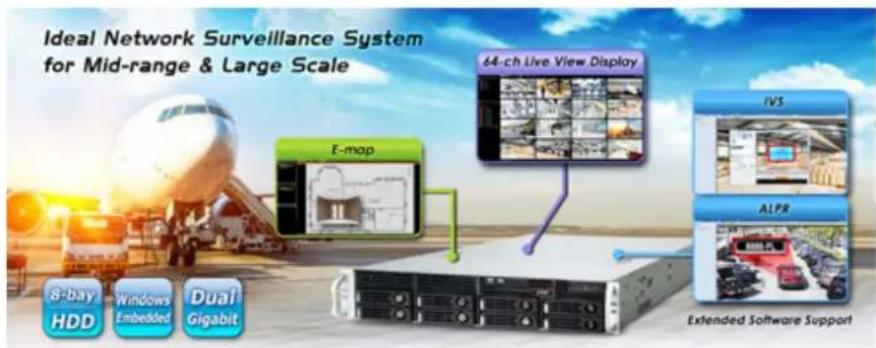
The NVR-E6480 features Gigabit Ethernet ports, eMap, video motion detection, automatic camera registration, and mobile apps for smart phone and tablet connectivity. The NVR-E6480, capable of recording 300Mbps of video bandwidth, supports a wide range of resolutions in H.264, MPEG-4 and M-JPEG formats. In addition, the NVR is able to work with extended software such as ALPR (Automatic License Plate Recognition) and IVS (Intelligent Video Surveillance). Through these value-added applications, the NVR is definitely a necessity to keep track of those critical moments saved as evidences when in need.
Instant Playback
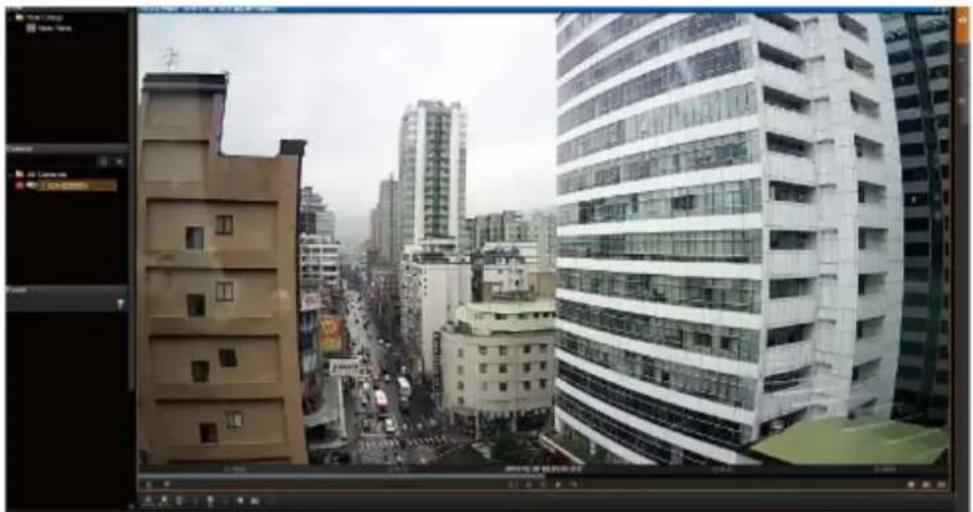
On the Live View page of the NVR-E6480's management interface, whenever you want to look back to check suspicious events of a camera channel you just missed, just hit the 'Instant Playback' button to bring up the window to review recent feeds. While you don't have to switch to the Playback page to do so, you can still have full live views of other channels simultaneously.
natural_image
Exterior view of a modern urban skyline with multi-story buildings and a busy street (no visible signage or text)Instant Playback in Live View
Dual Stream Management
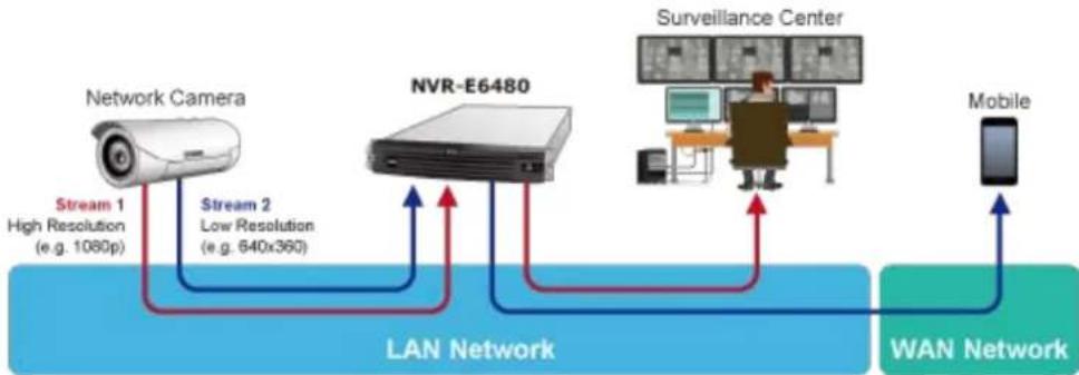
The NVR provides dual stream management in live view and recording functions. User is able to monitor or record stream 1 or stream 2 of dual stream devices. This design is able to reduce the CPU and memory loading of the NVR that handles a large number of channels.
flowchart
graph LR
    A["Network Camera"] -->|Stream 1 High Resolution (e.g. 1080p)| B["LAN Network"]
    A -->|Stream 2 Low Resolution (e.g. 640x360)| B
    B --> C["NVR-E6480"]
    C --> D["Surveillance Center"]
    D --> E["Mobile"]
    E --> F["WAN Network"]
Location Management with eMap
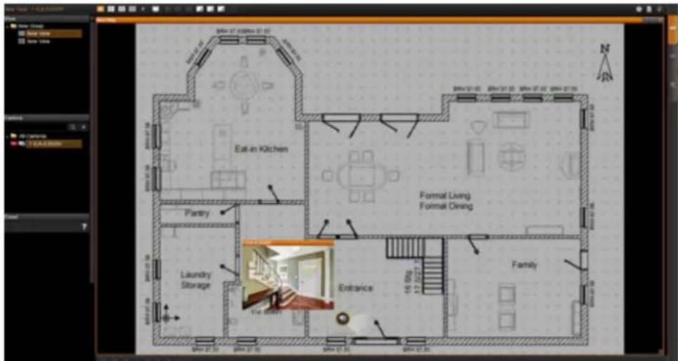
The eMap function helps visualize the layout of IP cameras in the surveillance network enabling you to quickly identify the location of each IP camera, especially when an alarm occurs. Just upload the pictures of the monitoring locations, and drag and drop the IP camera icons to the right place on the eMap. Once an alarm event happens, the camera icons will flash to indicate the event type for you to be alerted immediately and take necessary actions.
Remote Access via Mobile App, Web Browser or CMS
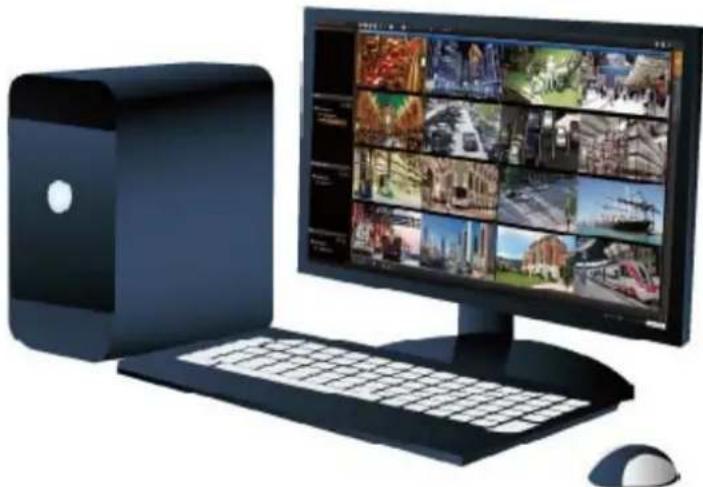
The NVR-E6480 provides central surveillance management capability with the adoption of its bundled Central Management Software (CMS). With the CMS, the NVR system is expandable for multi-sites management of up to 64 surveillance channels simultaneously. Besides, users are able to monitor the NVR via mobile app viewer or the Web browser anytime, anywhere.
natural_image
Computer setup with monitor displaying multiple surveillance feeds and a desktop tower beside it, accompanied by a mouse (no visible text or symbols)Large Storage Capacity
The NVR-E6480 is suitable for various network environments. Besides applications in retail stores and SMBs, the NVR-E6480 offers 8 SATA HDDs supporting RAID 0/1 function and is able to be applied in large scale surveillance facilities, such as banks, enterprises,
transportations, campuses, etc.
8 x SATA hard disk drive
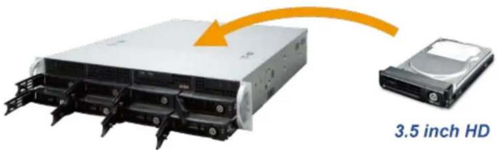
Provides scalability up to 48TB
1.1 Product Features
Hardware
■ Windows-based standalone NVR
■ 2U rack-mount design
■ Dual Gigabit Ethernet ports
■ E-SATA, VGA and USB interface supported
■ Audio line-in, line-out and mic-in jacks
Video & Audio
■ Simultaneous recording and live video streaming
■ Supports M-JPEG, MPEG-4 and H.264 compressions
■ 64-channel IP camera input
■ Video resolution up to 10 mega-pixel
■ 2-way audio support
Video Recording & Backup
■ Manual, event or scheduled recording of 64 IP cameras simultaneously
■ Supports recording frame rate up to 1920fps
■ Instant playback in live view
■ Supports 8 SATA hard disks (RAID 0/1) for storage, up to 6TB per HDD
■ Exports recorded video file in AVI or RAW format
Network Service
2 x RJ45, 10/100/1000BASE-T
IPv4, IPv6, TCP/IP, UDP, HTTP, DHCP, RTP, RTSP, DNS, NTP (SNTP), ICMP, ARP, SMTP, FTP, UPnP, LDAP, ONVIF
Easy Installation & Management
■ ONVIF compliant for interoperability
■ Supports multiple languages
Dual stream management
■ Location-based management with eMap
■ Up to max. 64 channels with the central management software
■ Supports USB keyboard and mouse
■ Remote access via mobile app viewer and Web browser
■ Cam Viewer E-series software supported – CV7-VA, CV7-LP
1.2 Remote Access
The following are the minimum PC system requirements for remote access:
| Operating System | Windows 7, Windows 8, Windows 10, Windows Server 2008 and Windows Server 2012 |
| Browser | Internet Explorer 10, 11 |
| CPU | Intel® Core i7-920 2.67 GHz |
| RAM | 4 GB of RAM |
| Network | Gigabit Ethernet is recommended |
| Hard Disk Space | 1TB |
| Display Resolution | 1024 x 768 |
1.3 Packet Contents
1 x NVR
1 x Power Cord
1 x Quick Installation Guide
1 x Universal Converter
1 x Front Cover
2 sets x HDD Tray Keys
1 set x Screws
1.4 Product Specifications
| Product | NVR-E6480 |
| Hardware | |
| CPU | Intel Processor |
| RAM | 2GB |
| Operating System Windows 7 Standard Embedded | |
| Ethernet 2 x RJ45, 10/100/1000BASE-T | |
| USB Interface | 6 x USB 2.0 for backup device and firmware upgrade |
| Video Interface VGA video interface | |
| Audio Interface Mic-in, line-in and line-out | |
| Storage Device 8 x 3.5" SATA II hard disk connectors; up to 6TB per HDD | |
| External Storage Interface | 1 x eSATA |
| LED | Power |
| Button | Power |
| Weight 11.4 kg (with 1 system HDD and front cover) | |
| Dimensions (W x D x H) | 482 x 560 x 88 mm |
| Power 100-240V AC, 4-2A, 50-60Hz | |
| Consumption | 200W |
| Camera | |
| Max. Channels 64-channel IP cameras | |
| Function | Manual, auto or ONVIF search |
| Video | |
| Compression | H.264, MPEG-4, M-JPEG |
| Resolution | 10MP, 5MP, 4MP, 3MP, 2MP, 1.3MP, 1MP, VGA |
| Max. Live Video Frame Rate (Local Display) | 6fps@10MP (1-ch), 15fps@5MP (1-ch), 8fps@4MP (1-ch), 15fps@3MP (1-ch), 30fps@2MP (1-ch), 30fps@1.3MP (1-ch), 30fps@1MP (1-ch), 30fps@VGA (1-ch)*The above performance was tested with the following parameters:H.264 compression and 3Mbps bitrate |
| Audio | |
| Audio Type 2-way | |
| Live View | |
| Display Layout Mode | Local: 1, 4, 5, 6, 8, 9, 10, 12, 16Remote: 1, 4, 5, 6, 8, 9, 10, 12, 16, 18, 24, 25, 35, 36, 48, 49, 64 |
| Digital Zoom Zoom in/out | digitally by PiP (Picture-in-Picture) |
| Manual Recording/Snapshot | Instant recording upon mouse click/Instant snapshot upon mouse click or hot key |
| Dual Stream Management | Live view of stream 1 or stream 2 of dual stream devices |
| Event Panel Displays event | status upon alarm or upon connection loss or recovery |
| Instant Playback Instant playback in live view window | |
| E-map Area maps with camera icons and small live view windows hyperlinks | |
| Playback | |
| Video Search Time/Event based | |
| Playback Control Continuous forward and backward playback with speeds 1x, 2x, 4x, 8x or frame-by-frame; pause; stop | |
| Manual Snapshot Instant snapshot from playback upon mouse click | |
| Digital Zoom Zoom in/out digitally by PiP (Picture-in-Picture) | |
| Synchronized Playback Up to 9 channels for local display; up to 64 channels for remote client | |
| Video Export Export video clips in AVI or RAW format | |
| Recording | |
| Recording Throughput Maximum total bitrate 300Mbps | |
| Schedule Recording Record video with user defined schedule | |
| Event Recording | Record video when the alarm event is triggered, including the pre-event buffered video clip |
| Frame Rate Setting | Different recording frame rate settings for non-event and triggered event |
| Manual Recording | Instant recording upon mouse click |
| Dual Stream Management | Recording of stream 1 or stream 2 of dual stream devices |
| Recording Frame Rate | Max. 1920fps in total; max. 30fps per camera |
| Monitor | |
| Max. Local Display Resolution | 1920 x 1200 |
| Network and Configuration | |
| Network Service | IPv4, IPv6, TCP/IP, UDP, HTTP, DHCP, RTP, RTSP, DNS, NTP (SNTP), ICMP, ARP, SMTP, FTP, UPnP, LDAP, ONVIF |
| Triggers and Event | |
| Event Type | Video motion detection, passive IR sensor, external device through digital input, video loss and recovery, network loss and recovery, server loss and recovery, disk full, disk not found |
| Event Action | Record video, pop-up window with live video, switch to hotspot window, play beep sound, activate external device through digital output, upload snapshot to FTP server, execute system command to activate other programs, eMail notification with snapshots, command a PTZ device to go to a preset point |
| Manual Event | Manually activate external devices through digital output via live view monitor |
| Scheduler | Define the schedule of event manager |
| Management | |
| Max. Number of Clients | 1 local, 3 remote |
| Privileges | Live, Playback, Setup, Global |
| User Interface | ● Graphic local user interface (Operated by mouse, keyboard)● Web browser (Internet Explorer 7 or above)● CMS utility● App viewer |
| Multiple Languages Support | Arabic, Czech, Danish, German, Estonian, English, Spanish, Finnish, French, Hebrew, Hungarian, Indonesian, Italian, Japanese, Dutch, Polish, Portuguese, Romanian, Russian, Swedish, Thai, Turkish, Vietnamese, Simplified Chinese, Traditional Chinese |
| Log Type | User Operation, Setup Device, Setup System, Setup Users, Setup Schedule, Setup Event, System Status, Request Log |
| Environment | |
| Operating Temperature | 0~40 degrees C |
| Humidity | 10~85% RH |
* Hard disks for storage are not included in the packet.
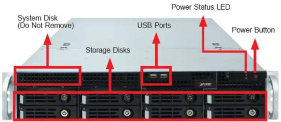
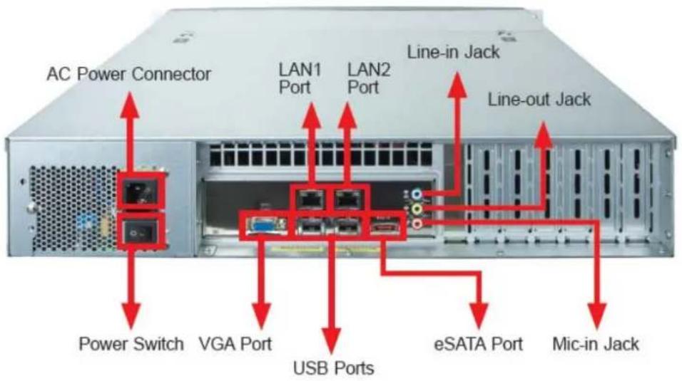
1.5 Physical Specifications
Front Panel
Rear Panel
ation Chapter 2. Hardware
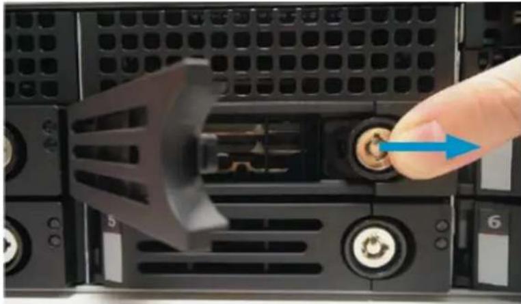
Make sure this unit is turned off, and insert the hard disks into the disk bays following the sequence of tray numbers.
- Slide the lock tab aside, and the hinge tab will pop out by itself.
natural_image
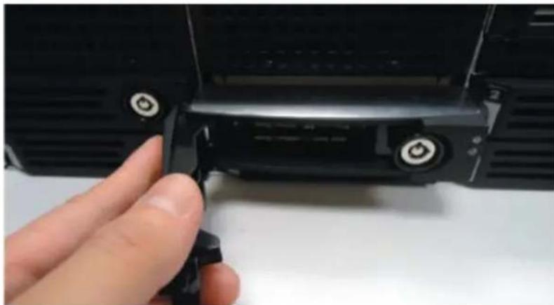
Close-up of a computer tower rear panel with a hand inserting a button to the left (no visible text or symbols)- Hold the tab lever and pull out the tray.
natural_image
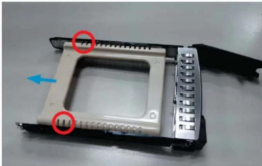
Close-up of a hand adjusting a black mechanical component with adjustment knobs (no visible text or symbols)- Loosen the two screws on the tray to remove the dummy disk. Secure the hard disk on the tray with the provided disk screws. Make sure the disk connector faces towards the SATA contacts inside the unit.
natural_image
Close-up of a white hard disk drive housing with cooling fins and a blue arrow indicator (no text or symbols)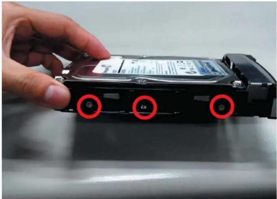
natural_image
Hand placing a CD-ROM drive into a black case, with red circles highlighting the three ports (no text or symbols visible)- Place your thumb on the lock to push the tray into position in the chassis.
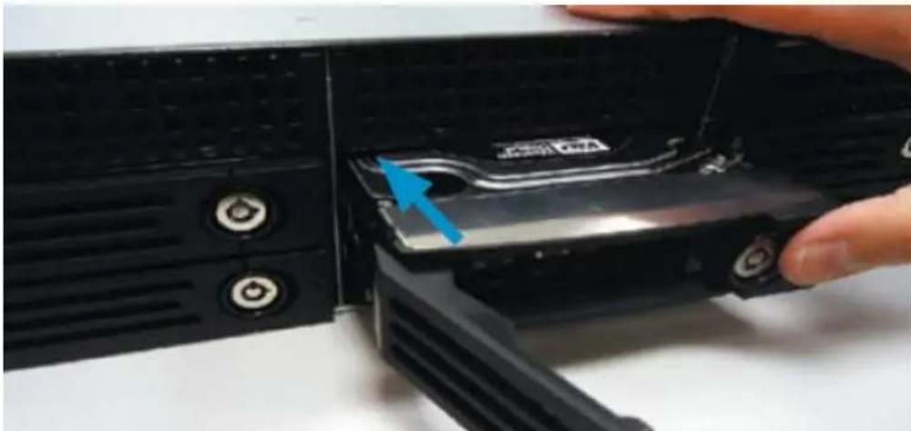
natural_image
Close-up of a hand inserting a CD drive into a black electronic device (no visible text or symbols)- Press the hinge tab until it clicks into place.
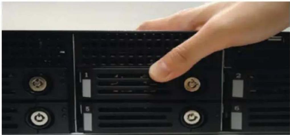
natural_image
Close-up of a hand pressing down on a black CPU socket with labeled ports (no readable text or symbols)- Align the left end hooks to the holes on the unit's left handle.
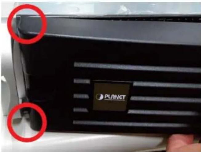
- Press the latch and push the right end towards the unit's right handle until it clicks into place.
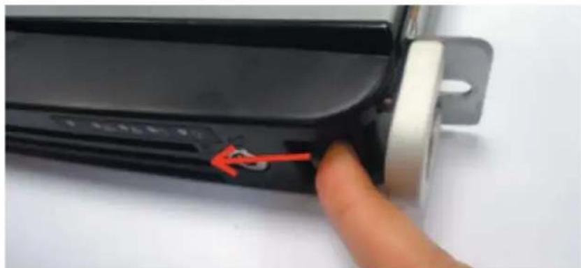
natural_image
Close-up of a hand pressing a button on a black electronic device (no visible text or symbols)- The NVR with front cover is shown below.
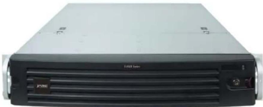
natural_image
Front view of a black FX80 Series hard drive unit (no visible text or symbols on body)2.1 Rack Mounting
This unit is designed to be mounted on a standard server rack, which occupies 2U (3.5") of vertical space.
Step 1: Allow a minimum of 5 cm clearance at the front and the rear for front-to-back airflow of the unit.
Step 2: Prepare a rack shelf rated for the unit's weight or purchase the rail kit from PLANET, and install that to support the entire unit.
Step 3: Secure the unit onto the rack.
2.2 Start Up
Step 1: On the unit's rear panel, press down the Power Switch to the side with "I" mark.
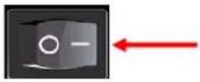
Step 2: On the unit's front panel, press down Power Button to turn on the unit.
Step 3: As this unit starts up, you will enter Windows logon screen, and input the password "admin" to log in as administrator.

The NVR-E6480 is strongly recommended to have it installed on the intranet in consideration of network security. It still could be attacked by hackers or malware although the NVR is equipped with built-in firewall.
stem Chapter 3. Log in to t
3.1 Access via Internet Explorer Browser
The computer where NVR server is installed is called Server Computer. You may access the server directly via Internet Explorer or the NVR-E6480 workstation on any other client computer.
Please open your browser, in URL box, type http://server_ip_address:port_number, e.g. http://220.228.146.22:8888 (generally, the port number is 80 and can be ignored in the URL). If your computer is exactly where NVR server is installed, you may simply type http://localhost:port_number.
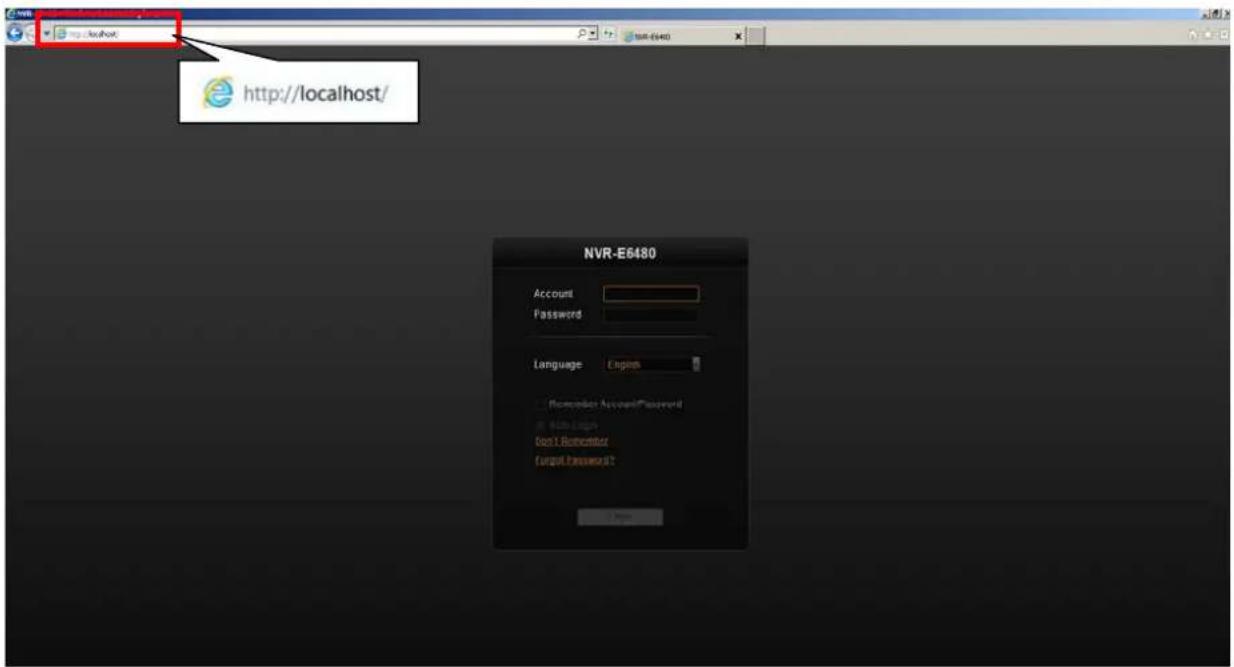
Login
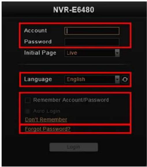
| A. | Enter Account & Password | Please obtain the Account & Password information from system administrator who has previously set up your User account in NVR-E6480 system. The default account and password are “admin”. | |
| B. | Change UI Language | To change UI language, select the desired language from the “Language” dropdown list. | |
| C. | Remember Account/Password | To have the server remember your Login Account and Password for the future, check “Remember Account/Password”. Click “Don’t Remember” will clear your input text and reset to default.To directly enter the main page every time you log in from this PC in the future, check “Remember Account/Password” and then “Auto Login” to skip the Login page. If your computer may be accessed by someone without proper authority, please DO NOT use either of these functions.To cancel auto-login, on the title bar, click →“Logout” to return to login page, and this function is cancelled. | 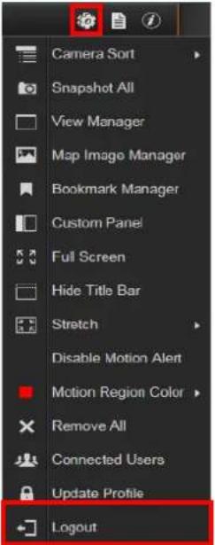 |
| D. | Retrieve the User Password | Once you forget the password, you may first contact the system administrator or try helping yourself with this procedure. NVR can send your password to the email address you saved in NVR server, and it is strongly recommended that you update your personal | |
information after your first login Please note that this procedure is only available when NVR server has accessed to SMTP service.
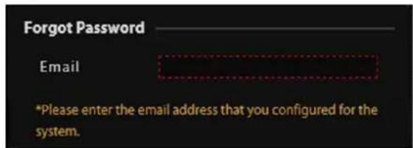
The email address input in Forgot Password window should match the one under your User account saved in NVR server.
3.2 Access via NVR-E6480 Workstation
The NVR-E6480 workstation includes a set of programs that provide the interface between users and NVR server. It may be installed in NVR server, or in the remote client computer that connects to NVR server via network. For the local client of NVR server, the NVR-E6480 workstation will start automatically after you login to Windows; for the remote client, please
double-click the shortcut icon
on your desktop to execute this workstation application.
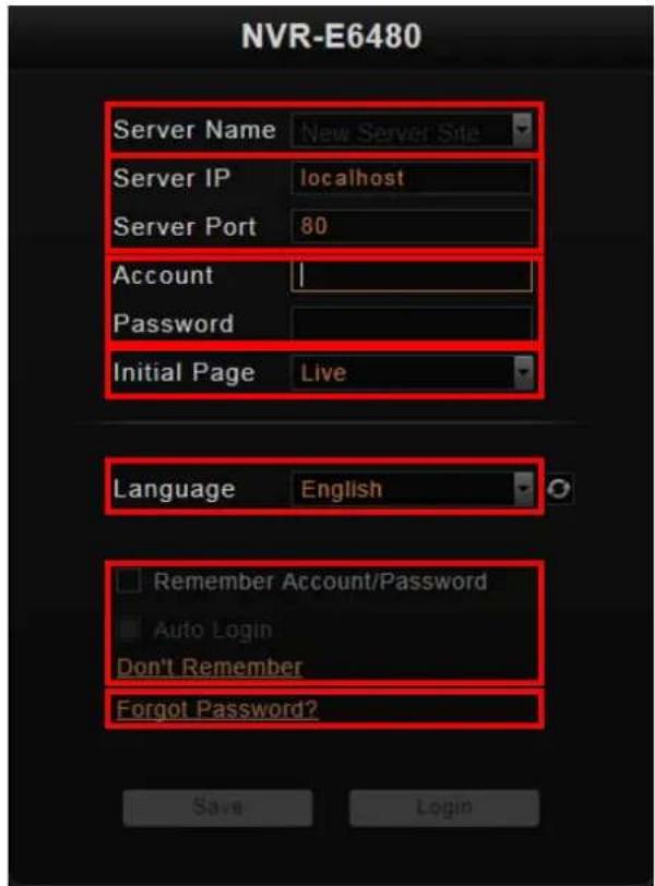
Login
Fill in the following fields and then click "Login" to log in to the system. The login process of Workstation is very much the same as that of Web browser.
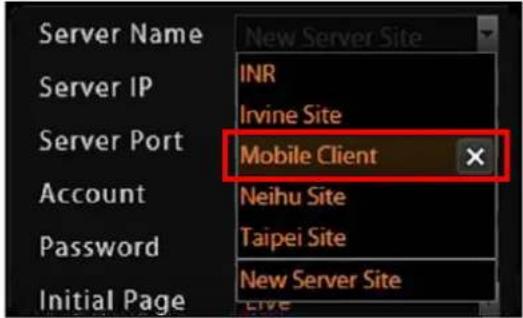
| A. Choose a Server | The NVR-E6480 workstation can remember multiple server sites and their login settings. Click on the arrow next to Server Name, and select a site from the dropdown list to log in. |
 | |||
| B. | Server IP & Server Port | ● In server IP field, key-inlocalhostor 127.0.0.1 if the NVR-E6480 workstation is on the same computer with NVR server. If you are connecting from another computer, please input the IP address of server computer, for example,220.228.146.21.● In server port field, key-in the server port number, default is 80. | |
| C. | Enter Account & Password | Please obtain the account & password information from system administrator who has previously set up your User account in the NVR-E6480 system. The default account and password are “admin”. | |
| D. | Choose the Initial Screen | 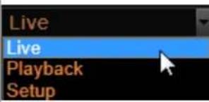 | The NVR-E6480 user interface consists of three main module screens:Live View,Playback and Setup; you may choose one where you would like to enter after logging in. Default isLive Viewscreen. |
| E. | Language | Choose a UI language from the dropdown list. | |
| F. | Remember Login Information | To have the NVR-E6480 workstation remember theAccountandPassword, chooseInitialPageand UI Language, and simply check“Remember login info”. Click “Don’t Remember” will clear your input text and reset to default.To directly enter the desired page every time you log in from this PC, check “Remember login info” and then “Auto Login” to skip the Login page. If your computer may be accessed by someone else, you might consider not to use either of these functions.To cancel auto-login, on the title bar, click→“Logout” to return to login page, and this function is cancelled. | 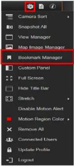 |
| G. | Retrieve the User Password | Please refer to D. Retrieve the User Password on page 18. | |
3.3 Change User Profile
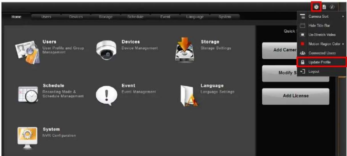
You can maintain your own account information on NVR interface without system administrator's help.
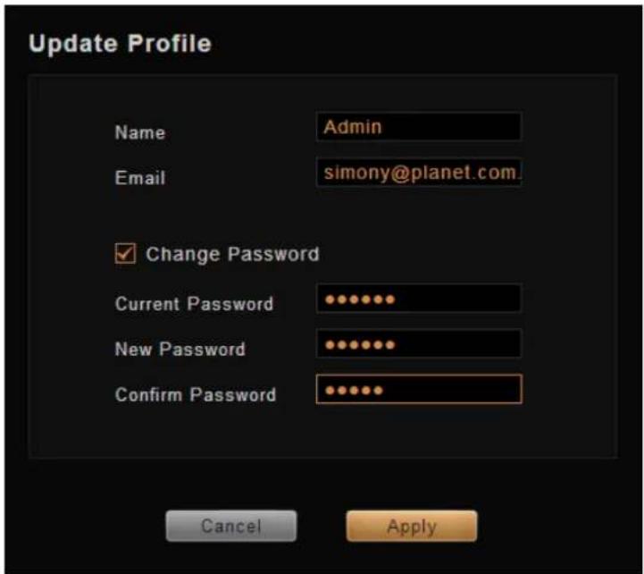
On NVR screen, click → "Update Profile". You may change the email address or password and then click "Apply" to save the settings to NVR server.
rview Chapter 4. N'
Unlike some NVR system products on the market, whose tree-like structure may easily confuse the user. The NVR-E6480's easy user interface structure saves you a lot of time and hassle going from one page to another. Once you log in to the system, you may switch to any of the main function modules: Live View, Playback and Setup on any screen.
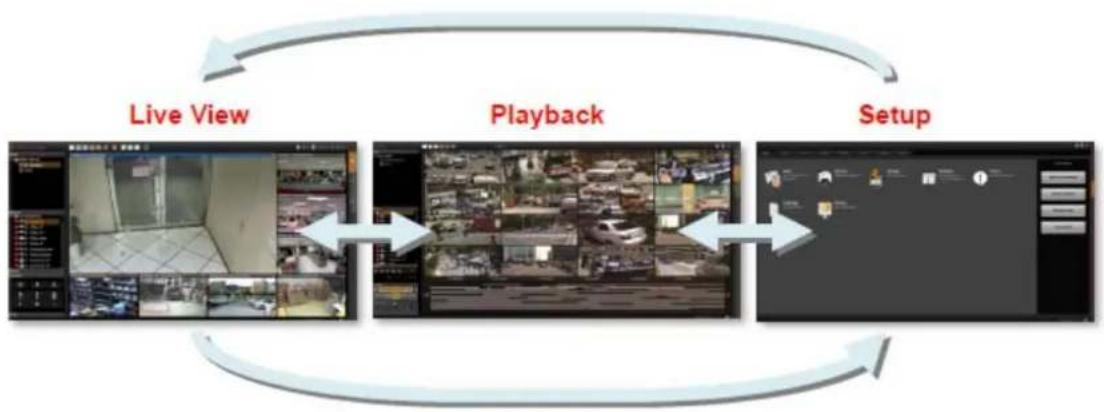
flowchart
graph LR
    A["Live View"] --> B["Playback"]
    B --> C["Setup"]
    C --> A
4.1 NVR Resident Tool Bars
These resident tool bars are important functions or links that you often need through all the operations in NVR system.
Tool Bar:
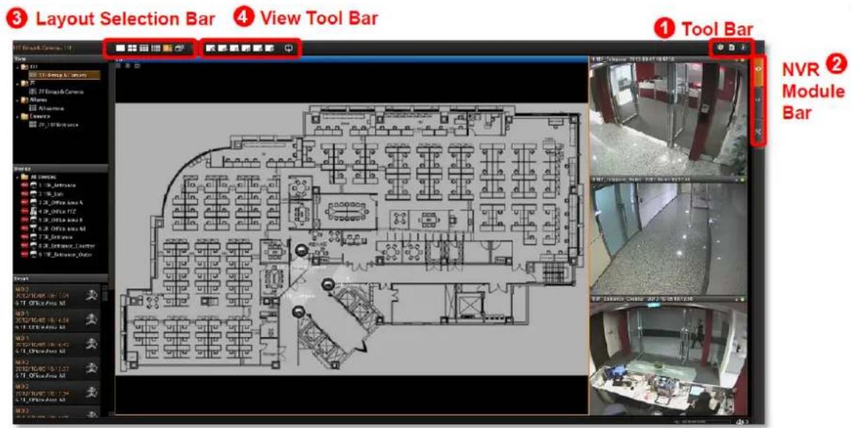
To the right of the title bar reside three links to most-used functions throughout all screens:

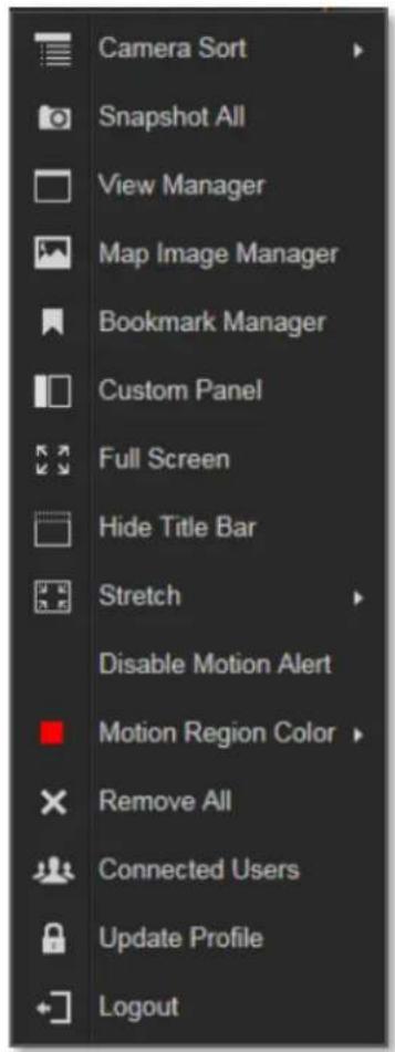
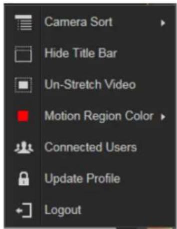
Options are certain useful functions you mostly need. The provided functions vary on different screens.
Live view Screen
Playback Screen
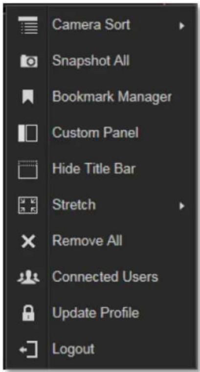
Setup Screen

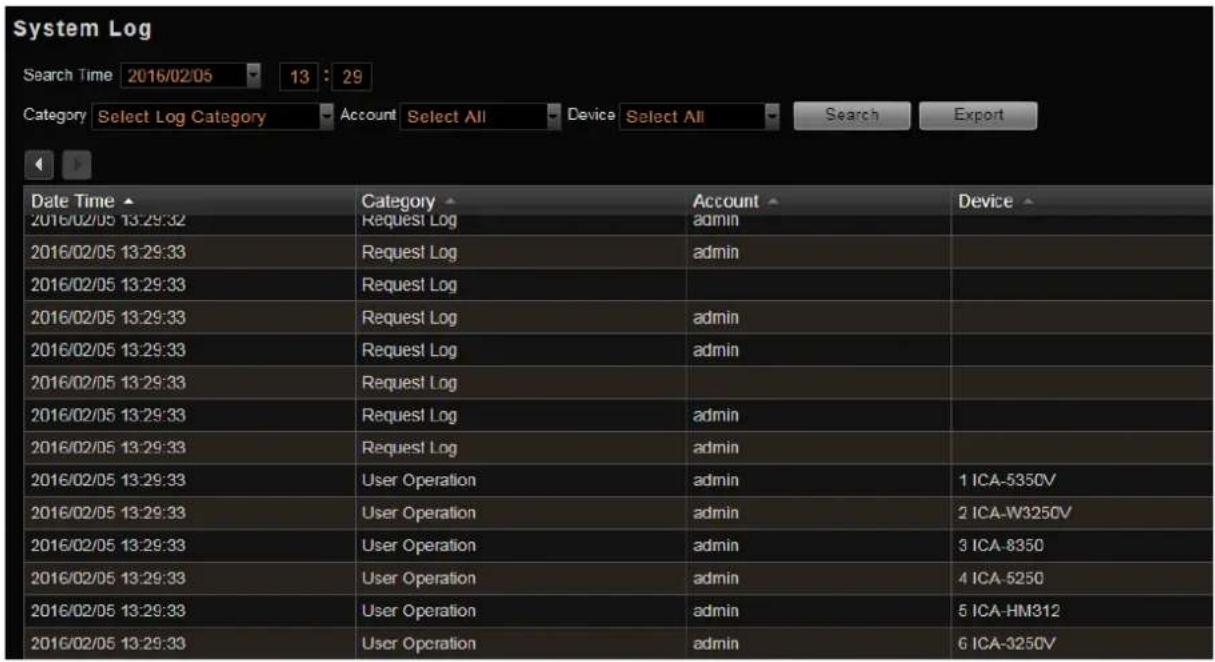
System Log provides the search module for you to review the records of user's behavior
on this server. This is only available when your User right has permission to access it.

About Us displays the software version number and required ActiveX Control version
number.
NVR Module Bar includes three main module screens: Live View, Playback and Setup.
You can click the button to enter the function page directly
Layout Selection Bar provides different layout styles for Live View and Playback screen.
View Tool Bar provides function keys for View editing on Live View screen.
4.2 NVR Main Screen
You will enter the live view screen after Setup Wizard. On the right are link buttons to three NVR major functions: (1) Live, (2) Playback and (3) Setup. You can click the orange button to enter the function page.
Live View
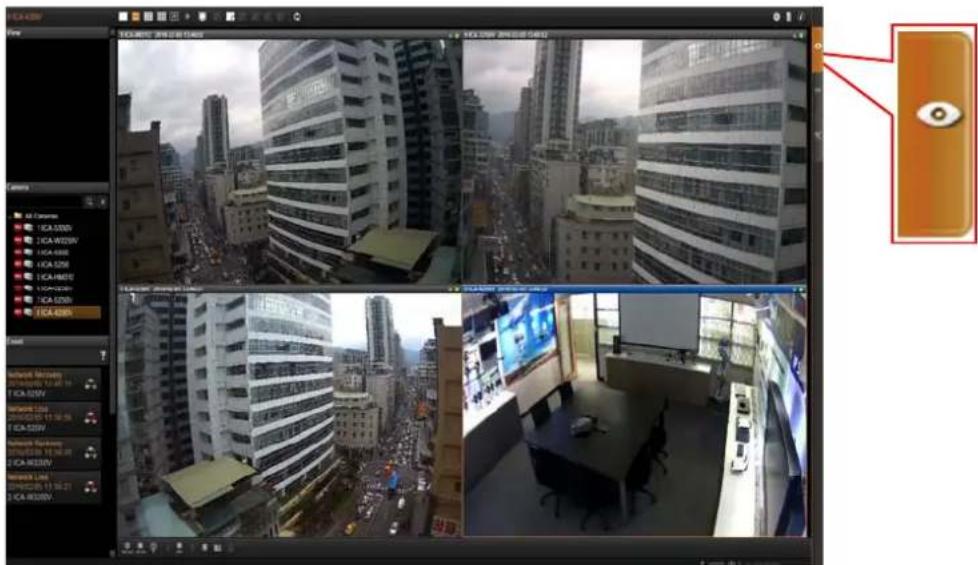
On Live screen, you can see live view from cameras, perform PTZ operations with mouse or joystick, view system log, receive alerts on the event panel, set up view layouts, perform manual recording or take a snapshot.
Playback
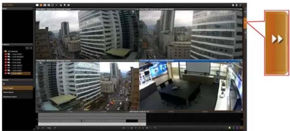
You may search and view playback of multiple channels synchronously. Snapshots or video segments can be taken from playback files. Recorded files can also be exported to AVI format here.
Setup
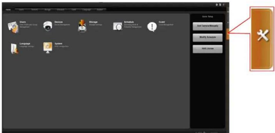
This screen allows you to perform user setup, device setup, event setup, schedule setup and system-wide settings.
View Chapter 5. Live
Live View is the interface where you see the live views from your cameras. It is where most of the security professionals access the surveillance system. Aside from keeping an eye on the video, you may also cycle through View layouts, drag and drop various cameras to the screen, review a log of events, take snapshots, control PTZ cameras, start or stop recording on a given channel, trigger Digital output and broadcast or talk to specific cameras. In this section, you will be given instructions on the said fundamental operations. To start, click Live View tab to enter live view screen.
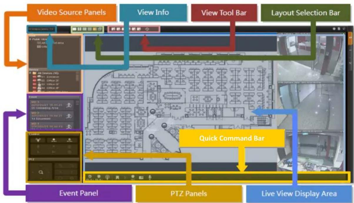
- View Info: Displays the information: [Current View name][Focused Channel name].
- Video Source Panels: View List panel and Camera list panel provide two types of video source for live view display area.
● Event Panel: Displays alerts of detected motion, abnormal system and device status.
● PTZ Panels: Displays the onscreen buttons for you to manipulate PTZ operations. - Layout Selection Bar: Offers different layout styles.
- View Tool Bar: You may create a view and save it using the buttons here. You may also assign specific layout to start patrolling.
● Live View Display Area: You may add up to 64 channels into this area to monitor them concurrently.
5.1 Select a View
In the NVR-E6480 system, a View refers to the layout where the live images of a few cameras are arranged in proper positions to suit the monitoring purpose. This is very similar to a Camera Group, which consists of cameras in the same physical location or with the same camera functions. For example, a View named First Floor may contain the cameras that are actually placed in the secured area on the first floor. Once created, each camera view is assigned to a certain channel on the layout style selected by creator.
Based on your User Group permissions, you may or may not own the privilege
- To create, edit or delete a Public View or a Private View
- To assign a specific View as default View
- To see all the cameras included in a Public View. Therefore, you may find certain view edit functions not available on the View Tool Bar.
To watch a saved View, simply click on it on View List panel.
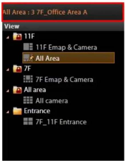
Above the View List panel title will display
[Current View name]: Camera name
● The Public Views are open to every User
- The Private Views are only available to the User who created them. You may not see this folder if without the User right to own the Private Views.
- The view with a pin on is set by system administrator as default view. You will enter this view every time you log in.
For details about how to create and edit a View, please refer to Chapter Customize Views in the NVR-E6480 Enterprise Administrator's Manual.
5.2 Select a Camera
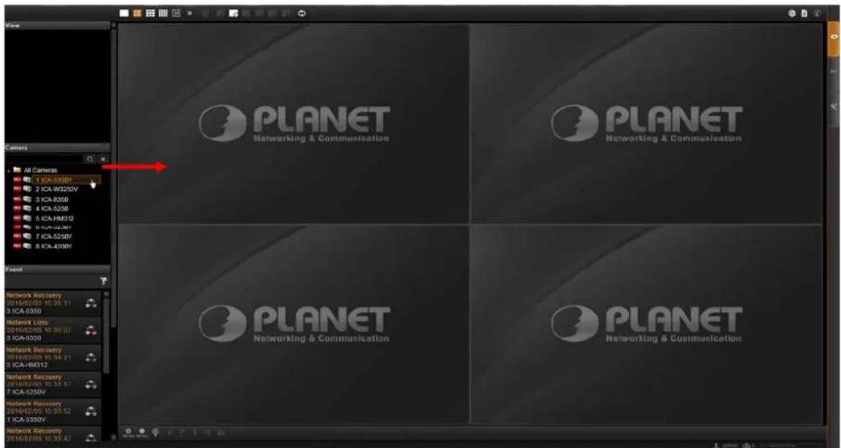
To watch the live view of individual cameras, you need to identify and add this camera video stream to a blank channel in display area. All the cameras that you are allowed to see are in the Camera list panel on the left. The permissions to watch different cameras are defined by your User Group, the details of which are managed by the system administrator. To pull in video sources to the display area:
From Camera panel, double-click on a camera or drag it to Display area. By double-clicking on "All Cameras", all the cameras will be added to the Display area.
5.3 Camera List
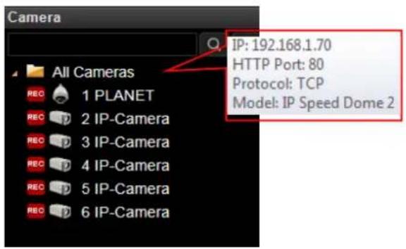
To view the camera information, put the cursor over the camera figure to bring the info box up.
In Camera panel, you may also sort the cameras in a different order. Click 📷 on the title bar, select "Camera Sort", and choose "by IP" or "by ID" as the sorting method.
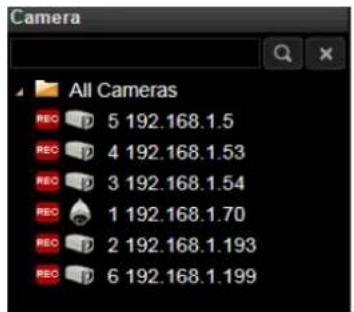
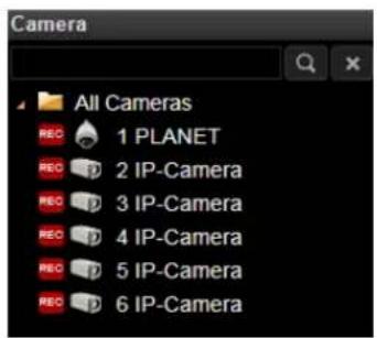
By Device IP By Device ID (default)
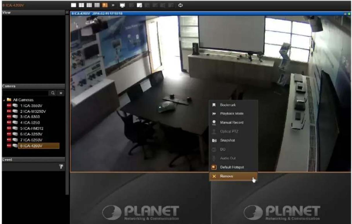
5.4 Remove a Channel
To remove a channel from display window, right-click the mouse for the quick menu on the channel, and select "Remove" to remove this video source.
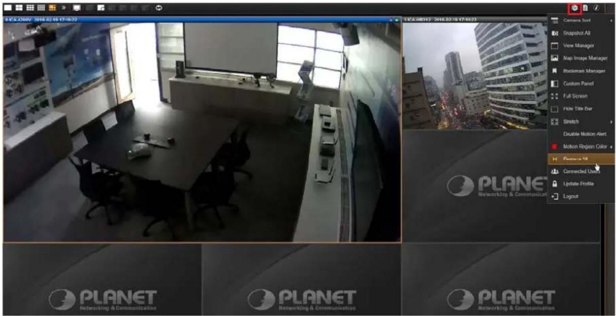
5.5 Remove All Channels
To remove all channels, disconnect all cameras by clicking in the title bar and select "Remove All".
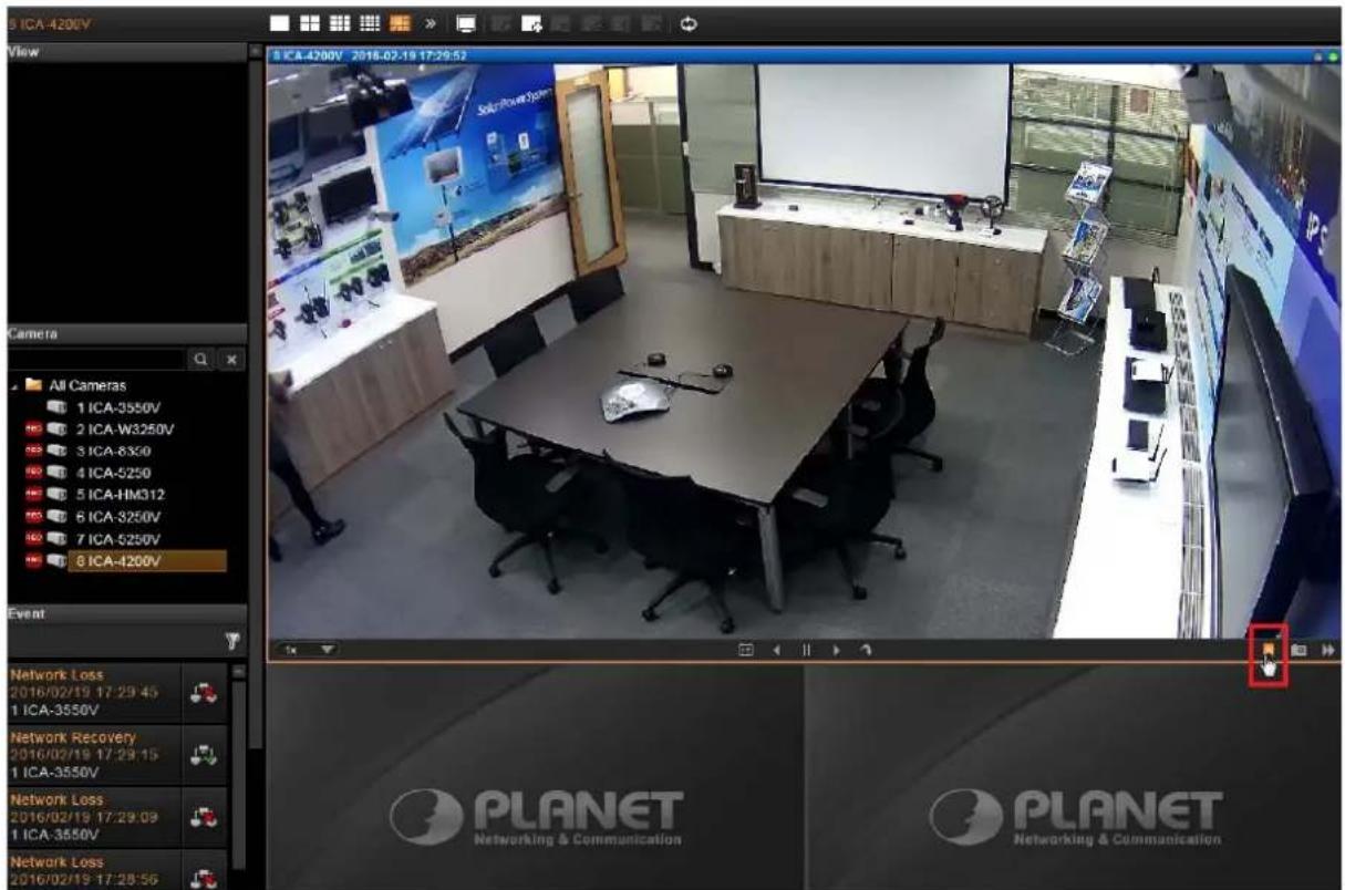
5.6 Add Bookmark
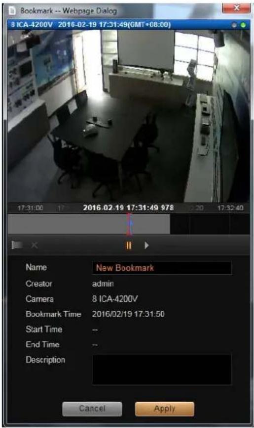
During live monitoring, you can create a bookmark of any time on any channel and edit your remarks about it. Select a channel and on the floating command bar, click on the bookmark button. On Bookmark window, input the name and description of this bookmark and then click on "Apply".
TIP Full Screen
On the system title bar, click 🔒 and then select "Full Screen" to enter full screen mode. Click the icon 🔒 on the top right corner of the title bar to return to normal mode.
Stretch/Un-stretch Channel
On the title bar, click 📋 and then select "Stretch" to make the width of video fill the window.
5.7 Enable View Patrol
You may have the saved Views patrol in turn. In this way, the views in different areas in your site may cycle through themselves for you automatically.
On the title bar, click 🔒 to select a saved patrol. As patrolling is running on Live View, click 🙏 to stop. You may create an Instant Patrol, which will only temporarily take effect during your current login.
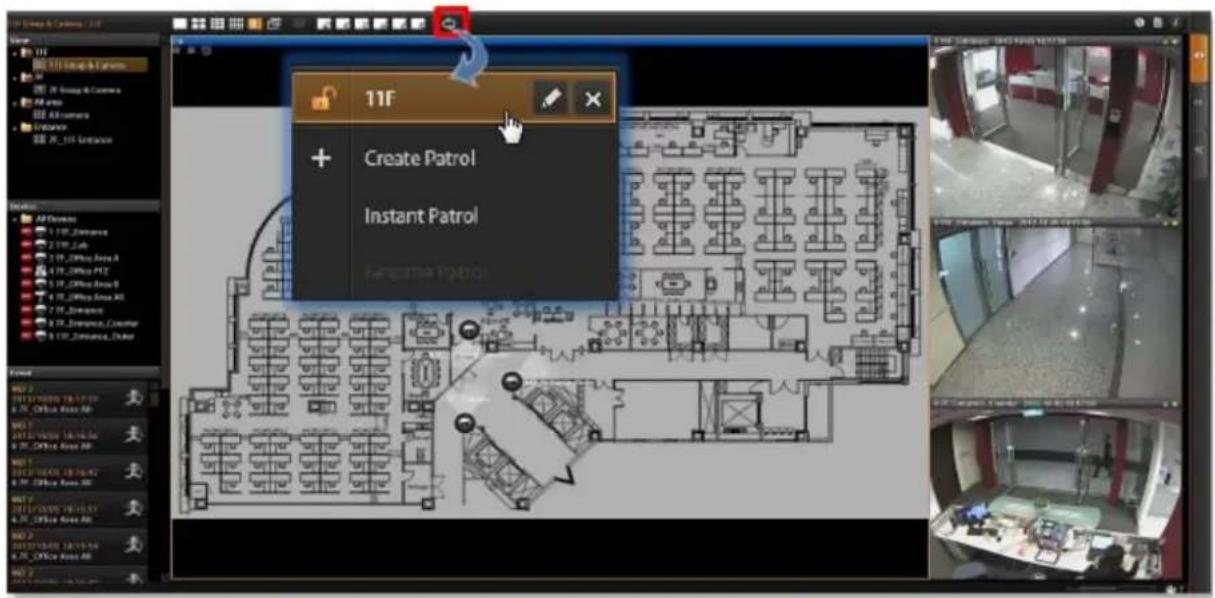
To configure the instant patrol, please do the following:
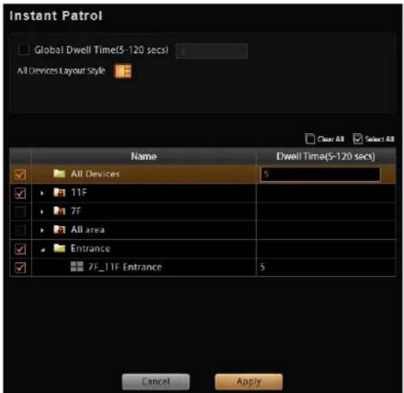
- Define the Global Dwell Time between the views. If you want to set a different dwell time length for individual views, do not check this option. Configure them separately in the table
below.
-
Choose the Views to display in patrol. If you select the All Cameras group, you will also need to select "All Camera Layout Style" for it.
-
Click "Apply" to save the settings. This patrol will instantly start running until you click
stem Chapter 6. Monitor the
6.1 Read System Alerts and Channel Status
On NVR live view screen, it is essential to observe the system status events. As unexpected environmental factors or human behaviors may take place to influence your surveillance system like power failure or internet connection interruption, NVR server may lose the connection with cameras, and hence you might lose the important video evidence.
6.1.1 Channel Status
The title bar of each channel window displays certain status information about this camera.
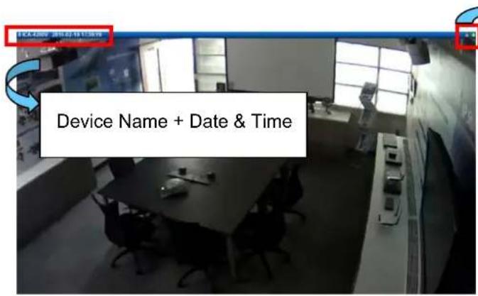
The indicators
The color of two indicators on top right channel title bar shows the following status:
•Right
:Device is connected with video presence
:Devices is not connected
:Device is connected, video is not received
• Left
: Performing manual recording
: Taking snapshot
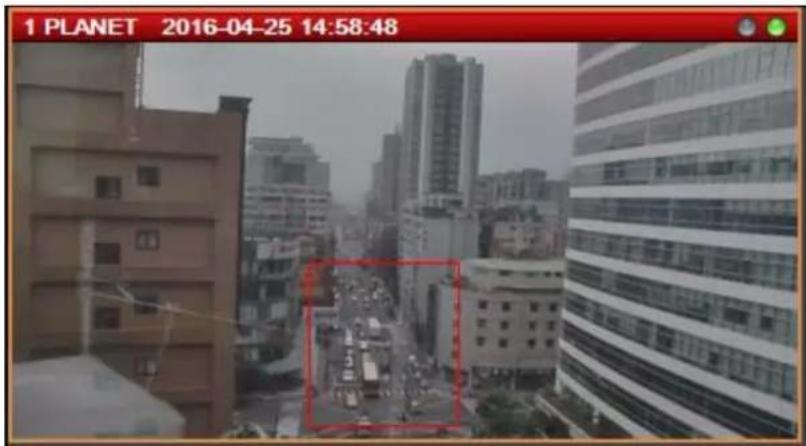
If this camera is triggered by events such as video motion, PIR motion or digital input device, the channel title bar would turn red for a while to alert you that some movements have been detected.
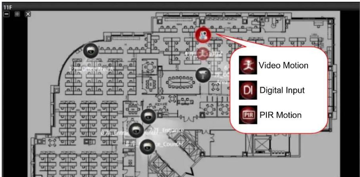
On a map channel, if a camera is triggered by events such as video motion, PIR motion or digital input device, an event icon will blink beside the camera icon for a few seconds. Click on the camera icon to see mini live view window on the map.
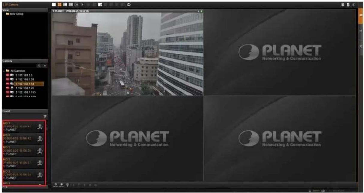
6.1.2 Event Panel
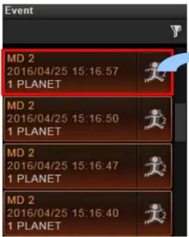
It is important to check out the messages pushed into Event panel all the time. These messages are arranged in a reverse-time order (newest on top, oldest on bottom).
The messages notify you of the following camera or system status:
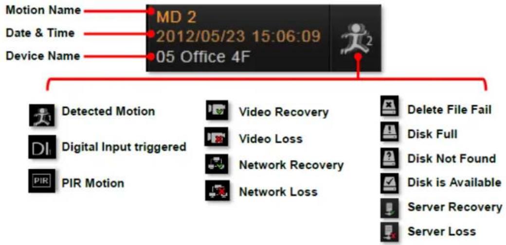
flowchart
graph TD
    A["MD 2<br>2012/05/23 15:06:09<br>05 Office 4F"] --> B["Motion Name"]
    A --> C["Date & Time"]
    A --> D["Device Name"]
    A --> E["Detected Motion"]
    A --> F["Digital Input triggered"]
    A --> G["PIR Motion"]
    A --> H["Video Recovery"]
    A --> I["Video Loss"]
    A --> J["Network Recovery"]
    A --> K["Network Loss"]
    A --> L["Delete File Fail"]
    A --> M["Disk Full"]
    A --> N["Disk Not Found"]
    A --> O["Disk is Available"]
    A --> P["Server Recovery"]
    A --> Q["Server Loss"]
When NVR server fails to connect a device, to get the video or have disk problems, it might be caused by a temporary network disconnection in your overall environment. The connection might recover after the problem is fixed. If not, please contact your system administrator.
6.1.3 Instant Event Playback
Among these types of Event messages, you may individually watch the event playback of a motion (video motion, DI or PIR) event or transmission status event (video recovery and loss, or network recovery and loss). To bring up the instant event playback window, double-click on an event entry:
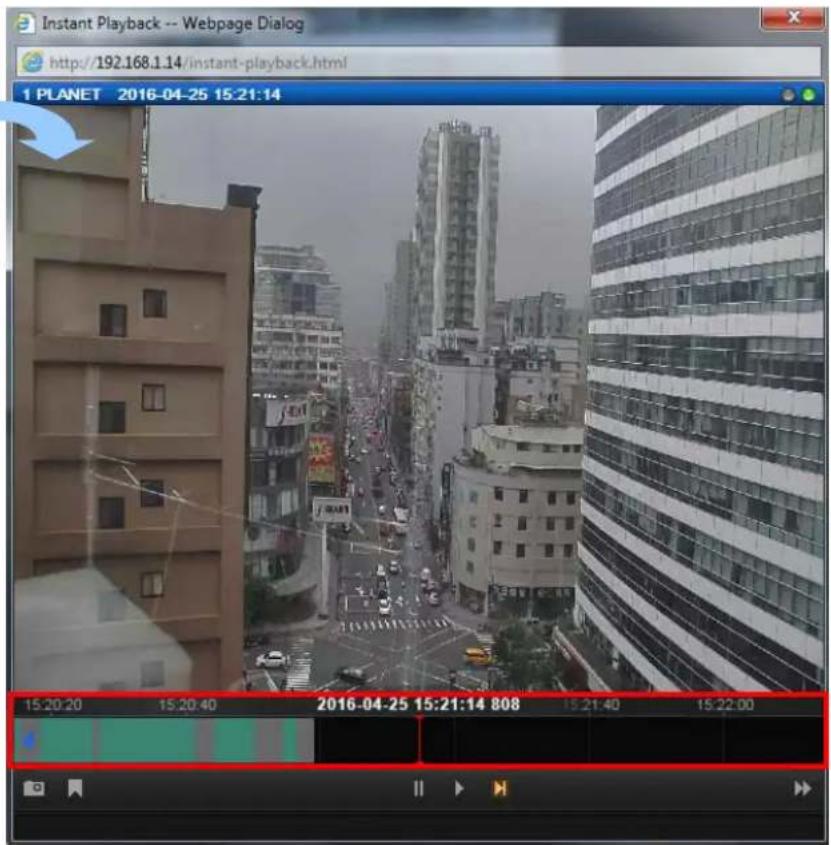
As the window pops out, it will immediately start playing live view stream. You may draw the time bar back and forth to search.
- Click ▶ to play video, 'to pause, or to play live view video.
- On time bar, click the blue mark or which indicates the event's occurrence, and then
to play back this event.

- Click to manually start recording the currently-playing video.
- Click to take a snapshot of this view.
- Click ▶ to switch to Playback screen.
- Click ✗ on the top right of the window title to close.
6.1.4 Pop-up Event Playback
Sometimes the instant event playback window would automatically pop up to notify you of events detected on certain camera sites. As the events in certain sensitive spots will have higher priority than other channels, your system administrator would apply this "Pop-up Event Window" function to these cameras. In this way, these critical events will be pushed into your sight actively.
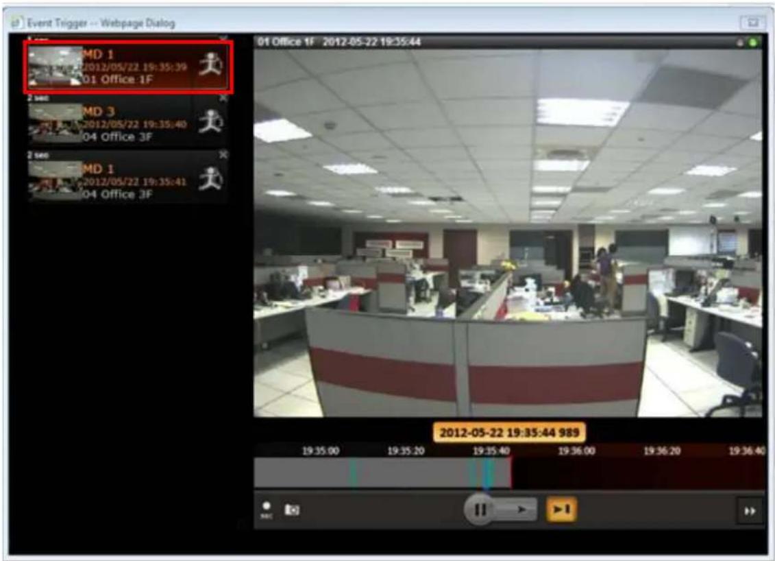
On the left of the window may list a series of motions detected within the same period. You may double-click on any entry to see its live view or play back the event. This window would automatically disappear after a while, and you may still look these events up in the Event panel.
6.1.5 Hotspot Window
In your Live View screen, the upper left window may sometimes display a camera video instead of the original channel. This is because the events detected in certain sensitive spots will have higher priority than other channels. Whichever View you are watching, the events detected by those cameras will be temporarily displayed in this window to catch your attention.
You can set any other channel on your live view screen to be the default hotspot channel.
Right-click on the desired channel and select "Default Hotspot"

6.1.6 Motion Region Indicator
The motion region indicator is a red frame that blinks when motion inside this ROI (Region of Interest) is detected.
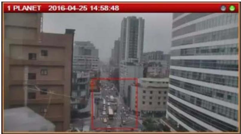
You can turn off the indicators of all channels on Live View screen. On Live View screen, click
→ "Disable Motion Alert".
6.2 Live View Operations
Aside from pure watching, there are more benefits provided by NVR server to accomplish more tasks. For example, you may make use of the audio function to commutate with people on camera side, look into more details with PTZ cameras, or navigate the whole scene on the maps.
6.2.1 Show Mini Live View Windows on a Map
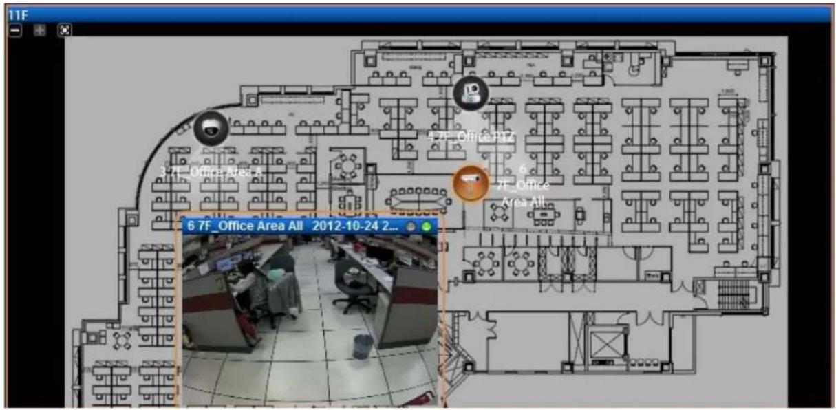
You may open mini live view windows of all cameras on a map channel to get an overview of what is happening on this map.
- Click on the icon to enter another linked map.
- Double-click on a camera icon to open its live view window.
- On the map channel, right-click and select "Show All Live View".
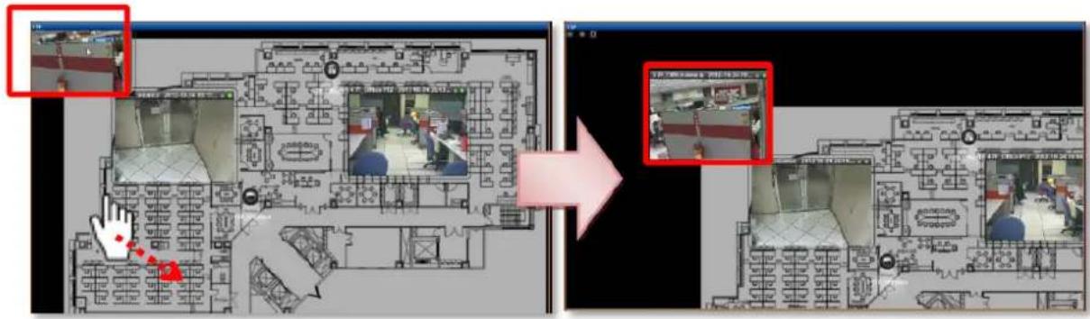
If certain mini windows appear out of view, you can drag on anywhere on the map to move the image until the window reveals.
6.2.2 Adjust Audio-in Volume
If one or more cameras are connected with an audio-in device like a microphone, or supports two-way audio function, the audio signal will be recorded along with video stream. You may listen to the real-time audio on Live View screen or recorded audio in Playback screen. In Live view, NVR server will send out the audio signal when you select a channel. On the
bottom right of Live View screen is the audio-in volume control.
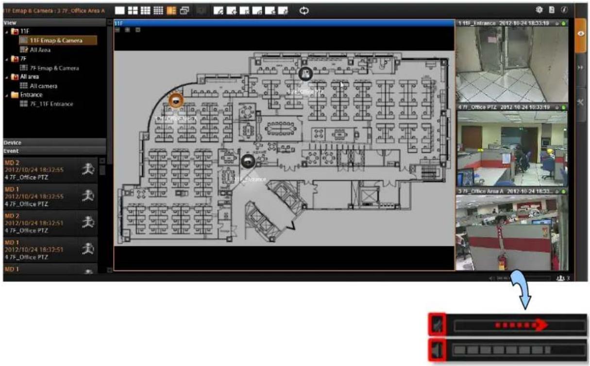
- To mute the channel audio, click
● To activate the channel audio, click
● To adjust audio volume, drag on the volume meter.
6.2.3 Send Audio Signal
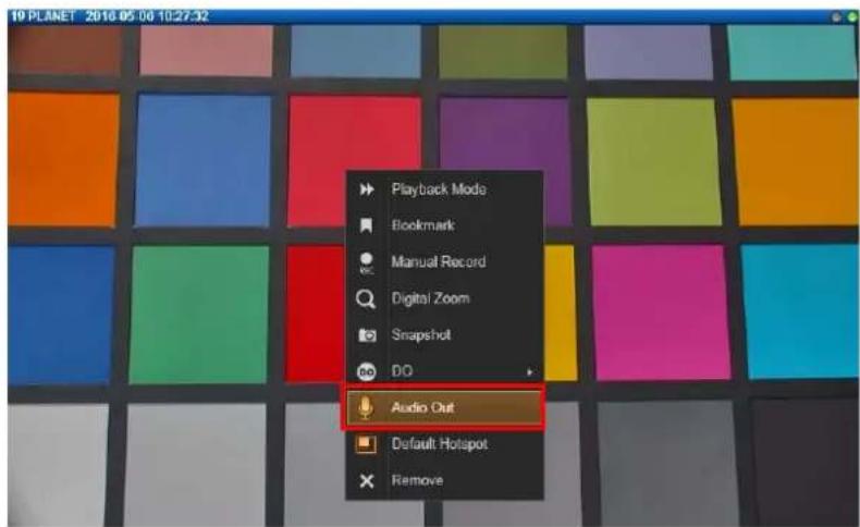
To talk to the audience through speaker connected to one camera, right-click on a channel to bring up the quick menu, and select "Audio Out". When this icon appears in orange, your audio-out function is activated, every sound you make through the microphone on your client computer will be sent out to this camera only.
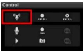
To broadcast to multiple cameras, click 📋 on Live View Control panel. Your audio will be sent to all the channels connected to a speaker in current View.
6.2.4 Trigger Digital-out Device
If a camera is connected with a digital-out device such as a door contact or an alarm, you may trigger it via NVR server on Live View screen. Do either of the following:
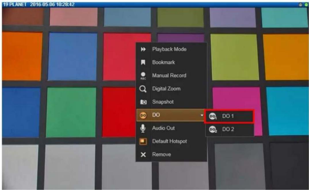
On the channel, right-click to bring up the quick menu, the DO icon will appear available if the corresponding DO device is connected. Click "DO" to trigger it, click again to stop triggering.
As a channel is focused, click 📄 on Live view Control panel, click again to stop triggering.
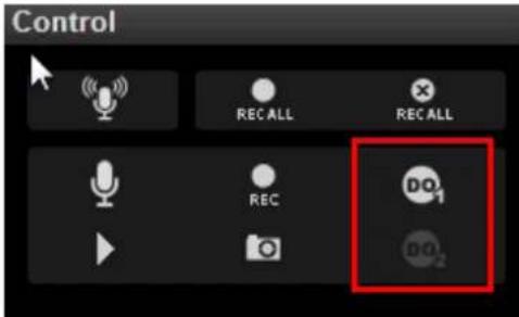

Triggering DO and sending audio to a specific device are only available on a single camera channel. On a map channel, you may do "Audio Broadcast" to all devices in this view.
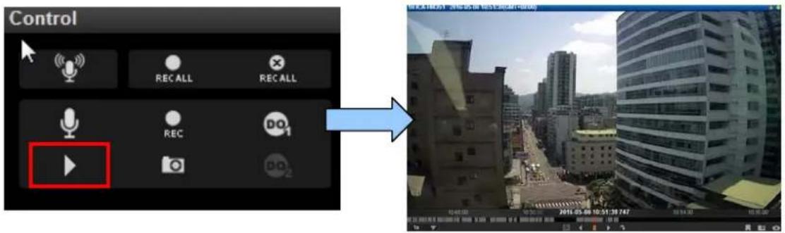
6.2.5 Watch Instant Playback of a Channel
You may watch the playback of any channel in a pop-up window on Live View without
switching to Playback screen. As a channel is focused, click on Live View Control panel.
6.2.6 Manual Recording
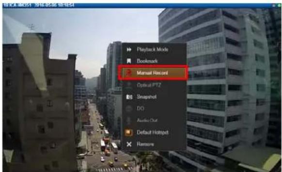
You may manually record the real-time video on Live view screen. This video will only be searchable in Playback. You may switch to Playback screen to find this clip (please refer to the section in this manual: How to Do Playback on page 41 for instructions). To do manual recording, do one of the following:
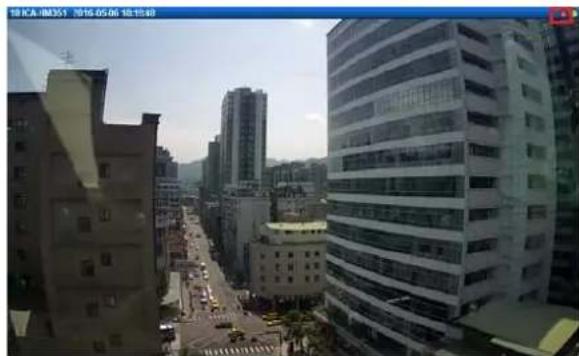
On a channel, right-click to bring up the quick menu and then select "Manual Record". Once the recording starts, the left indicator on the channel title bar will turn red. To stop recording, click "Manual Record" again on quick menu.
natural_image
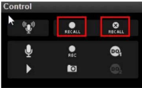
Exterior view of a modern urban skyline with high-rise buildings and a busy street (no visible signage or text)To manually record all channels in current View, on Live view Control panel, click RECALL to start; click RECALL to stop.
6.2.7 Take a Snapshot of Live Image
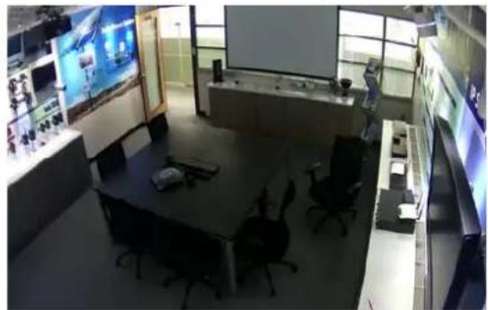
You may take a snapshot on a channel live image on Live View screen. The snapshot will be saved to default folder on your client computer as .jpg format (The system default location is Windows Desktop). You may find the location path on the bottom of NVR window after taking a snapshot.
Snapshot to: C:\Users\Wen.Cheng\Desktop\Channel01_20121024184041_759.jpg
You may do one of the following to take a snapshot:
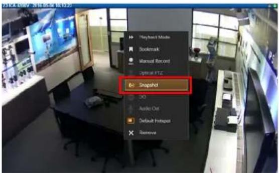
On a channel, right-click to bring up the quick menu and select "Snapshot". While the snapshot is being taken, the left indicator on the channel title bar will turn blue. After the picture is taken, the indicator will then turn gray.
natural_image
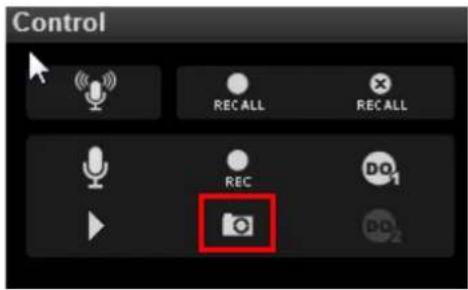
Interior view of a modern control room with display screens and office furniture (no visible text or symbols)As a channel is focused, click 📄 on Live view Control panel to take a snapshot.
6.2.8 Digital PTZ Operation
Regardless of the camera models, you may perform digital zooming on Live view screen.
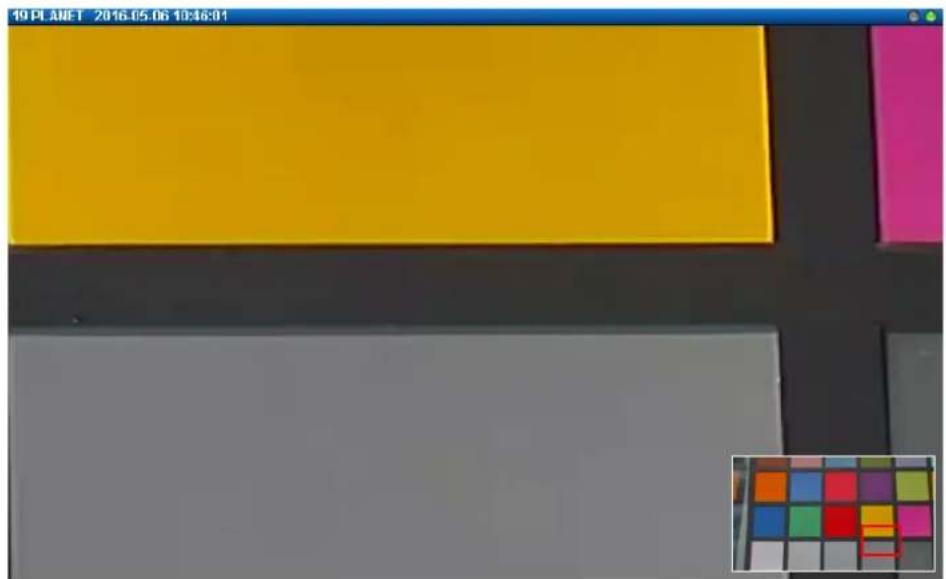
Click and drag a highlight rectangle over any channel, and the area highlighted will be displayed in the full live video window. In this mode, a picture-in-picture view will show in the lower right of live view window. A red rectangle will mark the currently enlarged view area within the full size video. You may drag the red rectangle over the image to zoom another area.
To go back to the original full video view, just right-click on the minimized Picture-in-Picture view.
natural_image
Color palette with a yellow rectangle and gray background, no visible text or symbols6.2.9 Optical PTZ Operation
If there is a camera supporting optical pan/tilt/zoom function in current view, you may operate it via the PTZ panel.
Once you select the camera, the optical PTZ controls will become available on PTZ Panel.
PTZ Panel Overview
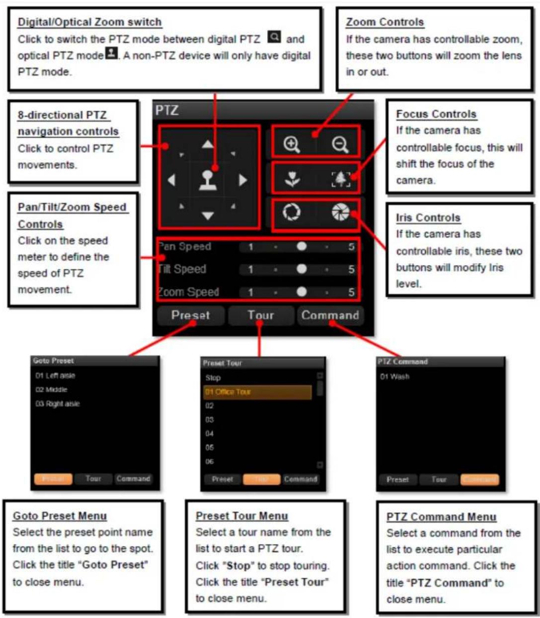
Using Mouse Controls
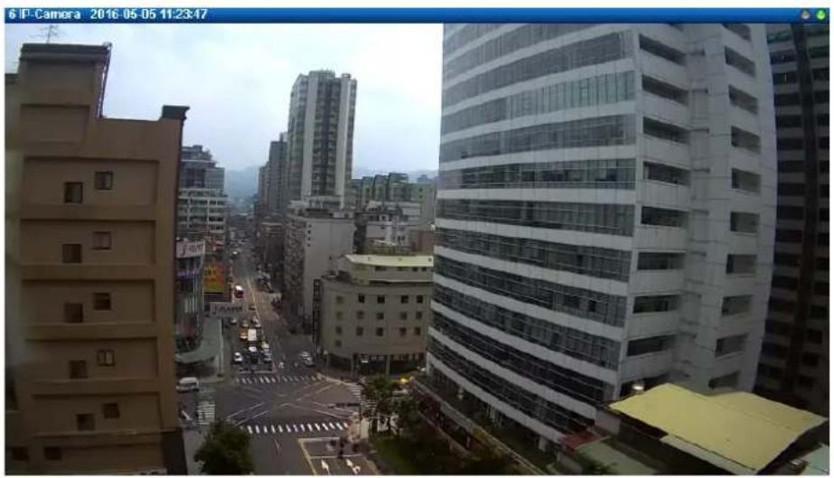
You may also use mouse to perform PTZ negation on a channel view or a mini live view window on a map.
Place the mouse over the channel to do the following PTZ operations:
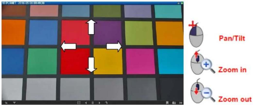
- To execute optical Panning and Tilting, click anywhere on the live window to allow the camera to move in that direction. The length of the direction indicator is proportional to the Pan and Tilt speed. The farther you place the cursor from the center, the faster the Pan/Tilt movement.
● To execute optical Zoom in or Zoom out, scroll the mouse wheel forward to zoom in;
scroll the mouse wheel backward to zoom out.
natural_image
Aerial view of a modern urban area with high-rise buildings and a busy street intersection (no visible signage or text)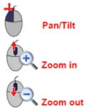
6.2.10 Navigate a Fisheye Camera Channel
On a fisheye camera channel, you may change the fisheye view mode and view point at will. What you see on Live View screen will not affect what is being recorded, and you can have an alternative of view mode when doing playback.
Change Fisheye Mode
On this channel, right-click to bring up channel menu; click "Fisheye Mode" and select one mode.
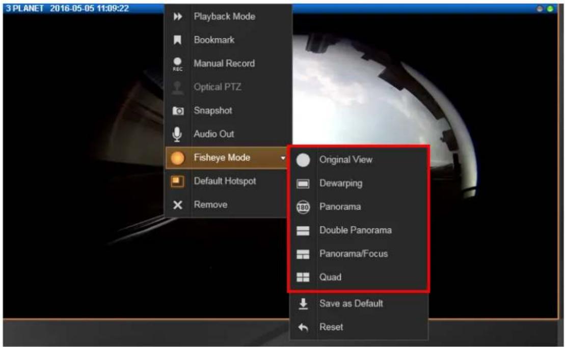
When you click on a channel which is set to such modes: Panorama mode with Wall mounting, Double Panorama mode with Wall mounting, Panorama Focus mode with Wall mounting and Double Panorama mode with Ceiling mounting, a clickable cursor will appear on the view to allow you explore the image.
natural_image
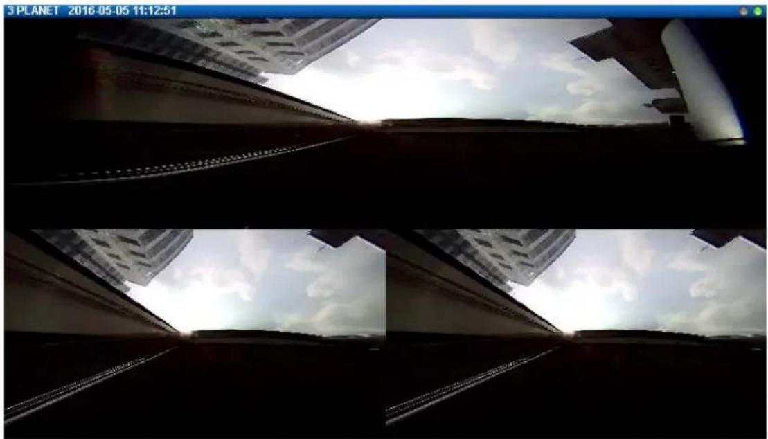
View from a camera showing a cityscape with skyscrapers under a cloudy sky (no text or symbols visible)PTZ Operation
Select a fisheye mode; click the entire channel or a region of interest to navigate this view.
- Use PTZ Panel controls to operate PTZ movements:
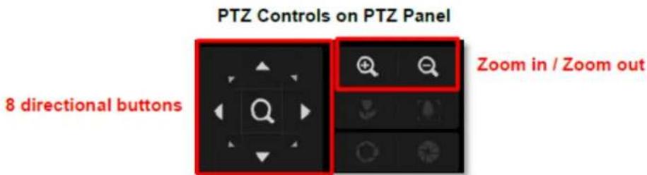
- Click the mouse anywhere on the view to pan/tilt; scroll the mouse wheel to zoom in/out.
- To reset the PTZ navigation area back to default viewing angle, right-click to bring up channel menu, and then click "Reset".

Note
Once a channel is changed to any of the following fisheye modes: Dewarping, Panorama, Double Panorama, Panorama/Focus or Quad, the resolution of this live stream will become 1920x1080, so will the resolution of the snapshot.
back Chapter 7. Play
NVR Playback is the NVR module that processes recorded clips, where you may search, play back and export video. Multiple channels can be played synchronizedly, and video clips may also be exported in either RAW or AVI format.
7.1 Playback UI Introduction
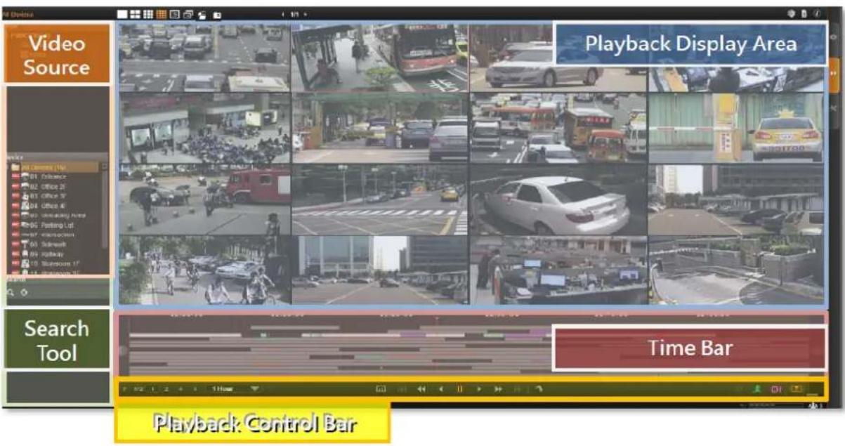
Playback screen consists of four function areas: Video Source, Playback Display, Time Bar and Search Panel.
- Video Source: Provides both saved Views and Camera Tree, you may drag a view or camera to Playback Display Area to view the recordings.
● Playback Display: You may have multiple-channel synchronized playback in this area.
● Time Bar: The time bar of the video source in Playback Display area will be shown here. You may drag on the time bar back and forth to your desired time spot. - Search Tool: Other than navigating the recordings by scrolling the time bar, you are provided with two search methods: IVS smart search and event type search. In this area, you will define your customized search filters.
- Playback Control Bar: All the controls related to video playing including play speed switch, play or pause button.
7.2 How to Do Playback
On NVR screen, click on "Playback" page to enter Playback view; none of the video sources
is selected in the beginning, and you have to select your desired channels.
Add Video Source
There are two ways to pull in video sources:
- In View area, click on a saved view.
- From Camera panel, double-click on a camera or drag it to Display area.
Through either way, you may add video sources, and their time bars will display in Time Bar area. Your playback operations and search will be based on these selected channels.
Meanwhile, you may change the layout styles from Layout Selection Bar on the title bar.
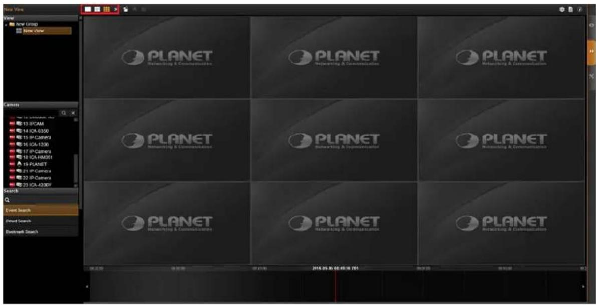
Remove Unwanted Channels
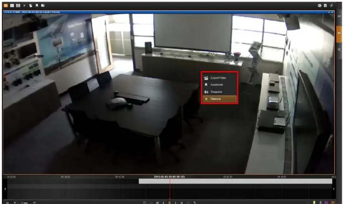
You will only need the desired channels to be kept in Display area, as you don't want too many unnecessary results after you perform a search.
To remove a channel from Display area, you may place your cursor over the channel, and right-click the mouse and then right-click the menu that provides "Remove", "Export Video" and "Snapshot" for a single channel.

The view of a map channel will not be recorded; therefore, it has no time bar or recordings for playback.
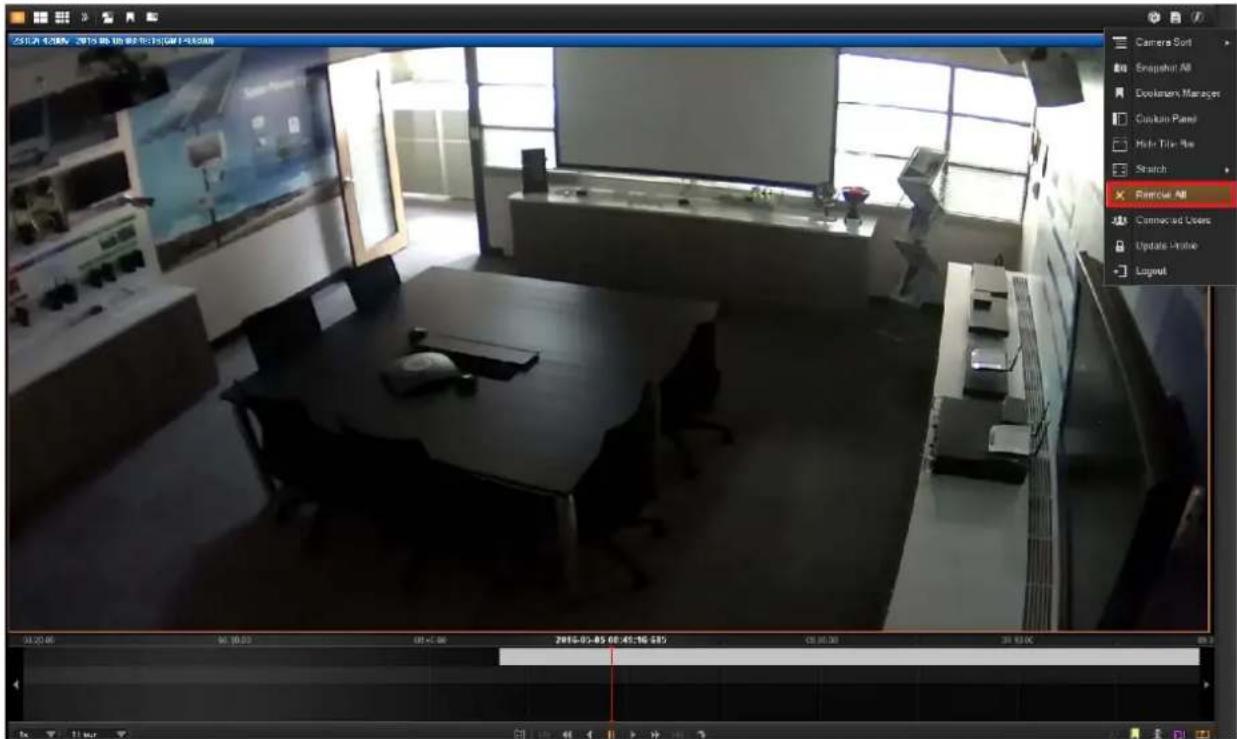
To remove all channels at one time, on the title bar, click to bring up the most used playback-related commands menu, and select "Remove All".
7.3 Search on Time Bar
You may focus on a certain channel as a search base. Its time bar will be highlighted as well.
-
To adjust the time frame seen on the Time Bar, you can click on any location on the Time Bar and use the scroll wheel on your mouse:
-
Scroll upwards to view a narrower time frame (For example, change the time frame from 1 hour to 30 minutes)
- Scroll downwards to view a broader time frame (For example, change the time frame from 1 hour to 2 hours)
Note that if your mouse doesn't provide a scroll wheel, this function can also be achieved by adjusting the "Time Bar Scale" in the Playback Control Bar.
- To find specific later time spot, drag the cursor to the left.
- To find specific former time spot, drag the cursor to the right.
- Click on to previous time section; to next time section.

Display Event Types
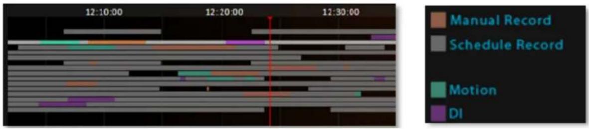
By default, the "Manual" recording will display in orange, while "Schedule" recording displays in gray on the time bar. To highlight specific events, you may enable the "Event" and "DI" event highlighters on Playback Control Bar.

Event Type Highlight Colors
Playback Controls
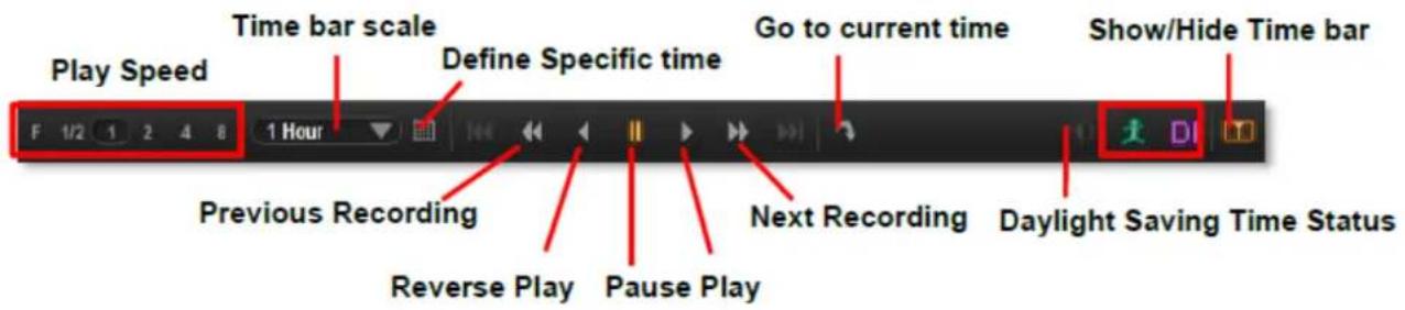
The playback related controls reside in Playback Control Bar. You may adjust the video play speed, do a reverse/forward play, or pause the video to spot your desired view. For non-continuous recording types such as DI, or Event recording, you may use the "Previous Recording" or "Next Recording" buttons to jump to the part directly.
Daylight Saving Time Switch

NVR Server will detect and display your client computer local time on Live View and Playback screen. Once you apply Daylight Saving Time rule on your computer, NVR server will automatically enable this function on Control Bar. By default, this function will be enabled automatically as daylight saving time begins. You may disable this function to view playback according to Coordinated Universal Time.
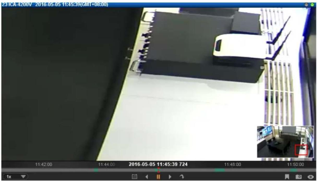
7.4 Digital Zoom on Channel View
Regardless of the camera models, you may perform digital zooming while the video is playing.
- Click and drag a highlight rectangle over any channel, and the area highlighted will be displayed in the full live video window. In this mode, a picture-in-picture view will show in the lower right of live view window. A red rectangle will mark the currently enlarged view area within the full size video. You may click and drag the red rectangle to see another area.
- To go back to the original full video view, just right-click on the minimized Picture-in-Picture view.
7.5 Explore Fisheye View
You may change to the desired fisheye view mode on Playback screen. To select a fisheye camera channel, right-click to bring up the channel menu→Fisheye Mode→select one view mode.
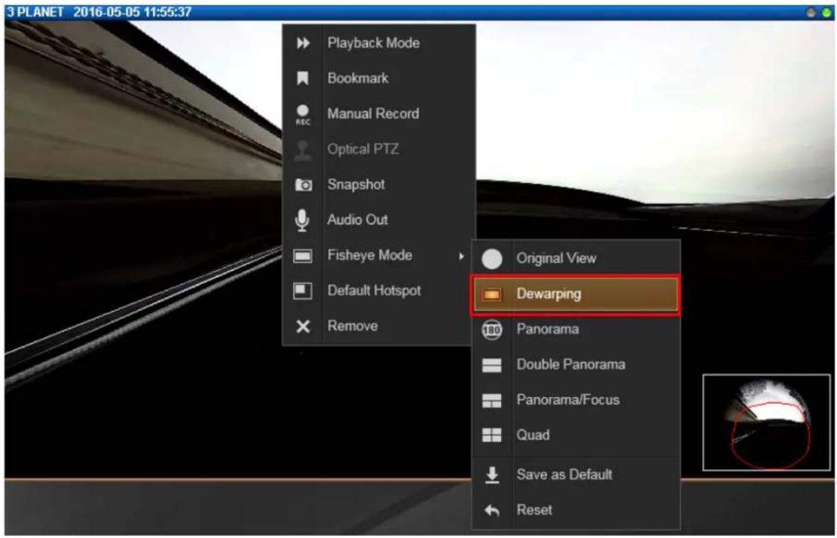
In a view mode where ePTZ operation is available (e.g. Quad mode), you may explore the region of interest using mouse or PTZ Panel at will. For ePTZ operation instructions, please refer to Navigate a Fisheye Camera Channel on page 38.
7.6 Search by Time
If you simply want to skim through the footage record around a certain time, you can start by locating the specific time on the time bar.
-
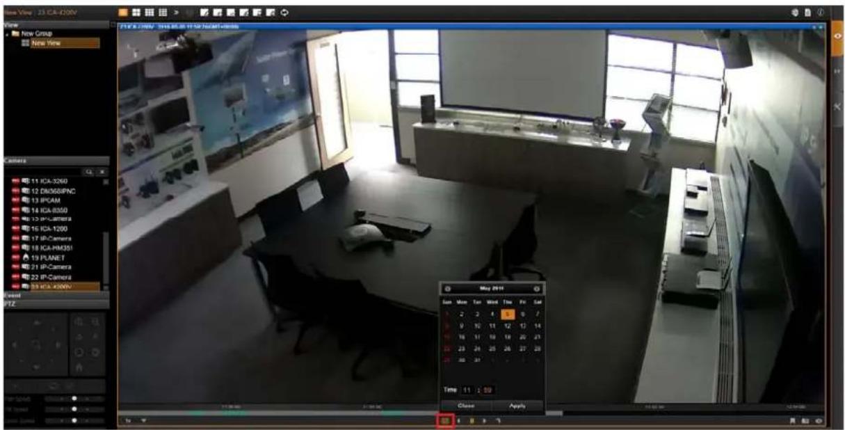
Double-click on your desired channel or drag it to the display window. The channel view will appear in the window.
-
On Playback Control Bar, click 📄, and specify the target date and time on the calendar window, and then click "Apply".
-
The time bar will immediately locate the target time.
7.7 Search by Event Type
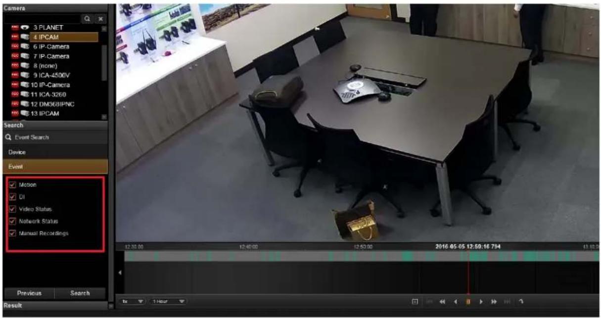
If you are clear about (1) When (2) as which event type (3) Where the incident happened, you will not need to drag on time bar all the way to the spot. The event search tool can sort out the video clips that match your criteria.
- Double-click on your desired channel or drag it to the display window. The channel view will appear in the window.
- Drag time bar to the target time.
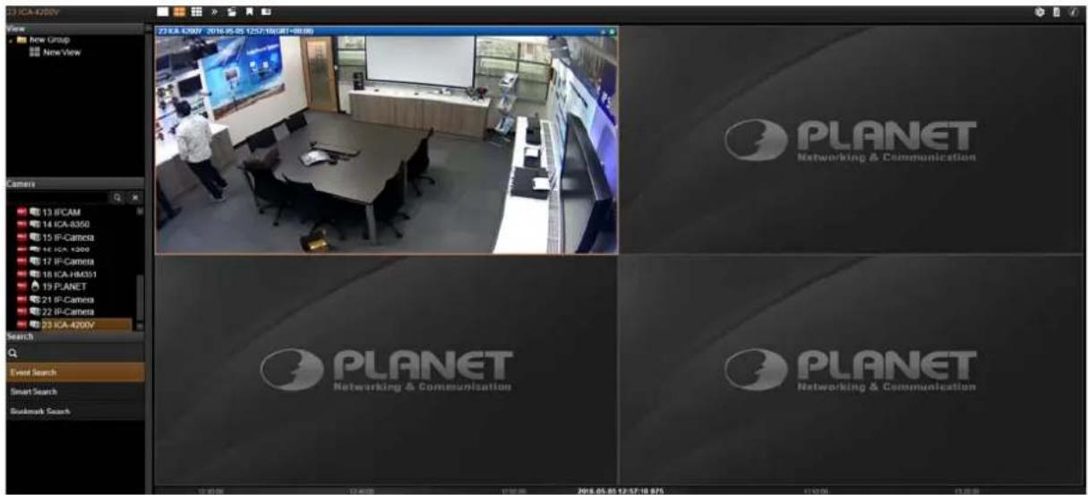
- On Search Tool panel, there are three options, such as Event Search, Smart Search and Bookmark Search.
- Select an event type of event search, and you can select an unwanted filter and delete it by unchecking the option.
- Select the desired filter and click "Apply" to start searching.
7.8 Search by Video Analytics
NVR server is equipped with two useful video analytics that can perform advanced search – Motion and Tamper.
Motion
- Unlike the typical motion detection method, this motion video analytics algorithm can detect a maximum of six regions in a view, including rectangle regions and polygon regions.
Tamper
- A camera that has been tampered with is not able to serve its purpose. To avoid this, NVR offers an algorithm to detect whether any form of tampering has been done to a camera, be it in the form of redirecting the angle of the camera, de-focusing the camera, covering, or spray-painting the camera.
To start,
- Double-click on your desired channel or drag it to the display window. The channel view will appear in the window.
- Drag time bar to the target time.
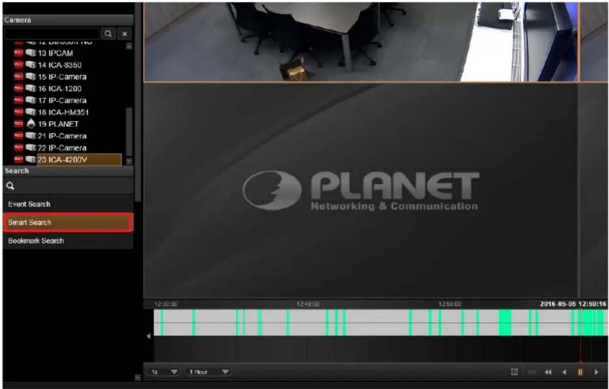
3. On Search Tool panel, click "Smart Search".
- Define the time range.
- Select the video analytics type
-
Click "+" to create this filter. You can select an unwanted filter and delete it by clicking on the "x" on the right.
-
After this filter is created, draw the regions on the channel view. (You can define a total of six regions for a motion filter, while tamper filter will analyze the whole camera view.)
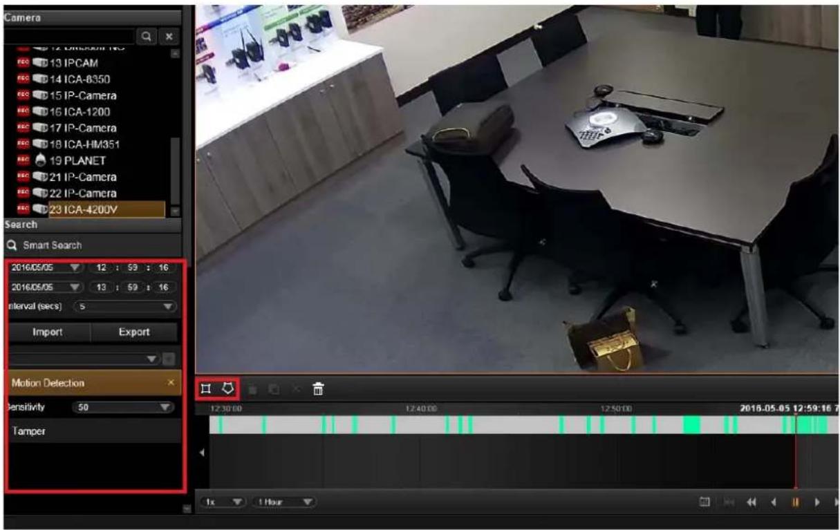
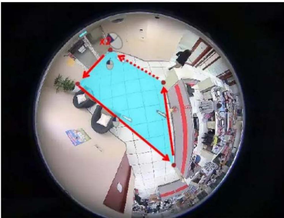
If the area you want to mark does not fit to the form of a rectangle, you may also want to draw a polygon by selecting the icon. To draw the lines for the sides of your polygon, click your cursor to mark the endpoints of each line. Double-click on the final endpoint of the final line to confirm and highlight the polygon in light blue, as shown in the illustration below. Make sure your lines connect (a minimum of three lines) to form a closed shape.
- Click "Apply" to start searching.
To create a new search, simply double-click on a camera on Camera list, and follow the steps mentioned above again.
7.9 View Search Results
The search results will then start being generated in thumbnails in Search Result Viewer window. However, it might take a few seconds if a large number of results are found. The thumbnails are listed in sequential order, left-to-right and top-to-bottom. You can drag on the Search Result Viewer to your desired time to find the snapshots of the incidents.
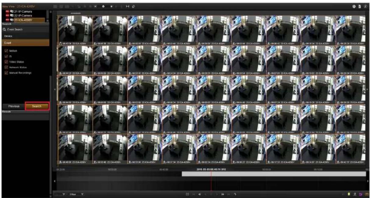
For easy exploring the search results, on Search Result Tool Bar, you can
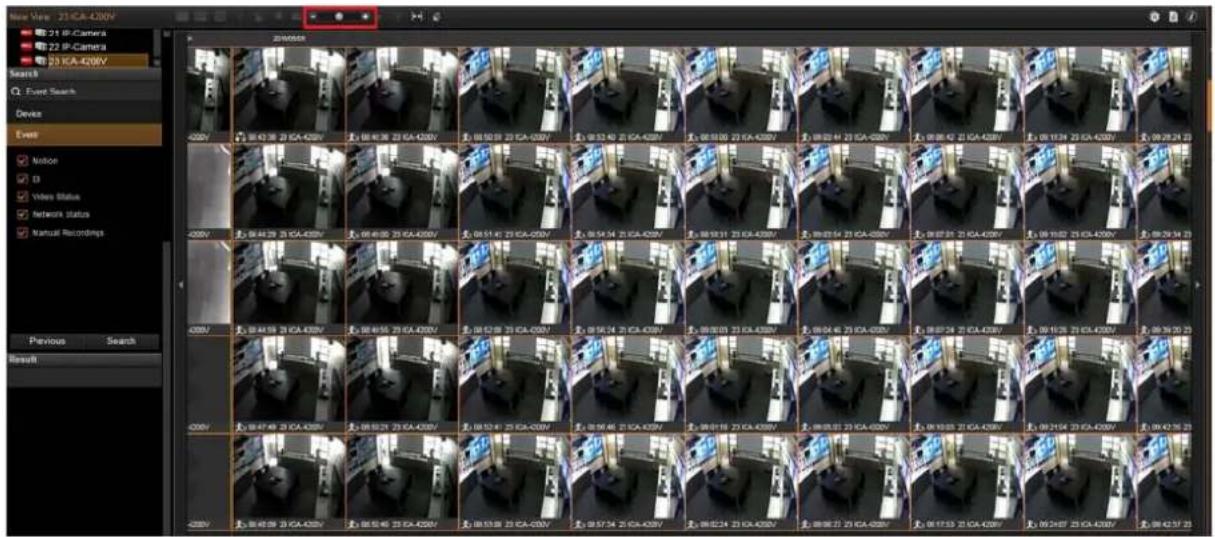
Adjust the size of the snapshots, the smaller the thumbnail's size is, you can see in the view.
- Select a thumbnail and click
to download its snapshot.
- Select a thumbnail and click
to directly start playing this event.
- Select a thumbnail and click
to view the event card list instead of thumbnail view.
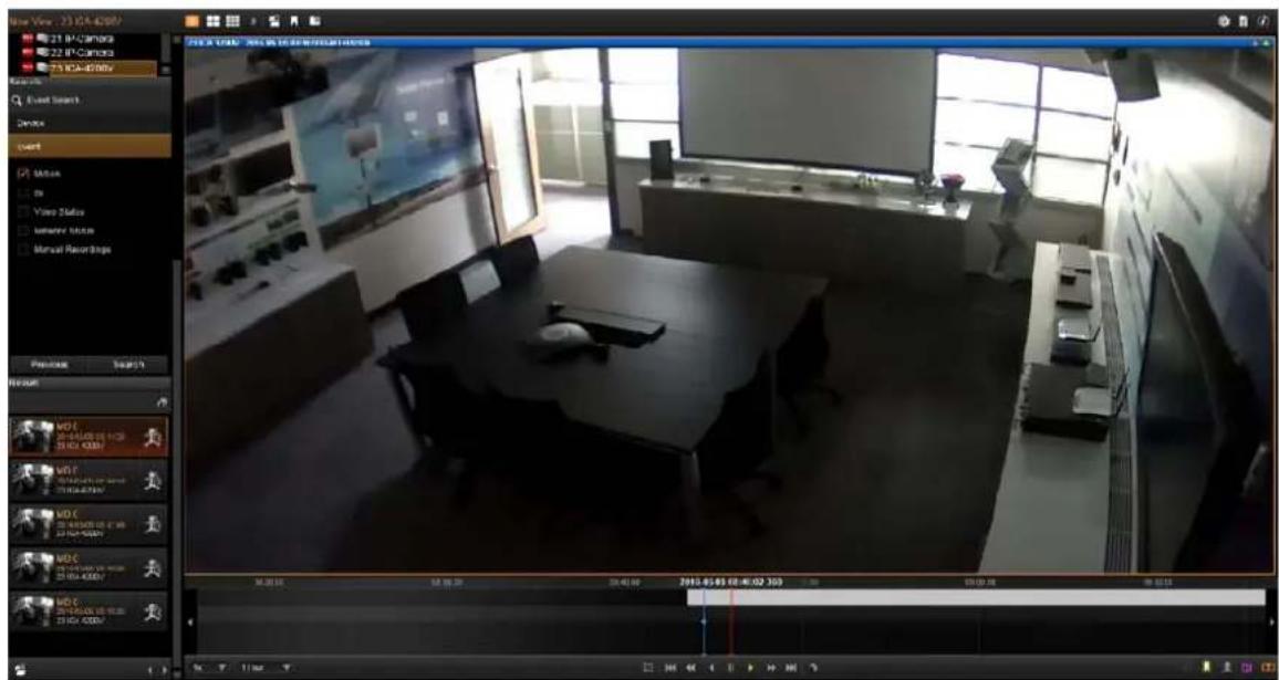
The event card list will be displayed in the Search Tool panel. You can click to browse through the event list, or double-click on an event card to start playing this event.
To return to thumbnail view, click
7.10 Take a Snapshot of the Playback View
You may take a snapshot of a channel live image on Live view screen.
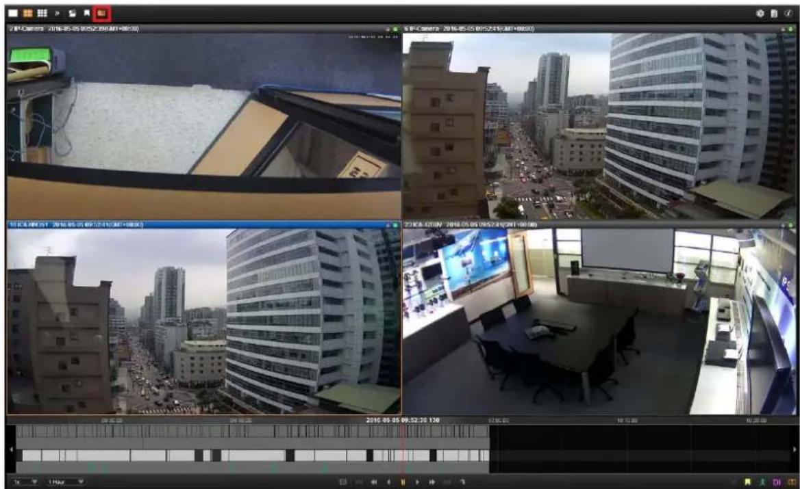
The snapshot will be saved to default folder on your client computer as .jpg format (The system default location is Windows Desktop). You may find the location path on the bottom of NVR window after taking a snapshot.
Snapshot to: C:\Users\Wen.Cheng\Desktop\Channel01_20121024184041_759.jpg
7.11 Export the Recordings
NVR playback offers two choices of video format for the exported video. The *.raw file, as the original video file format captured from video source, is able to be played on PLANET CV7-VA and CV7-LP software. You may download the software from http://www.planet.com.tw/en/product/product_list.php?id=47898
The*.AVI file, as the most widely adopted video format on Windows system, can be instantly transferred by NVR server and played directly in Windows Media Player.
Before starting to export the video, please make sure there is enough memory space on the hard drive of your destination computer.
To play the exported *.AVI file in other video players, you must have FFDShow or DivX codec installed in your computer. They can be found over the internet at the following
sites:
http://sourceforge.net/projects/ffdshow/
http://www.divx.com/en/software/divx
Define the Section of Exported Video on Time Bar
You may define the video duration on time bar during the playback. In this way, you don't spend extra time and effort on finding the specific date and time information.
- On time bar, drag to the start point of the video, right-click to bring up quick menu and then select "Mark Export Start".
- If yesterday point does fully deflation will turn yellow as you drag to another point. Drag to the end, right-click to bring up quick menu, and then select "Mark Export End".

- As both start point and end are set, you may right-click again the quick menu and find these two options are already grayed out. Select "Export Video"
Depending on your scenario, you may first set the end point and then the start point.
Other than defining the time duration, on the time bar, you can rest the time cursor
on a desired time and then click 📄 to enter Export Video window. The default
total length of two minutes.
time duration will
7.12 Set the Export Video Settings
You may export video with or without defining the time duration beforehand since you can configure all the settings on Export Video window. On Search Result Tool bar, click to enter the window.
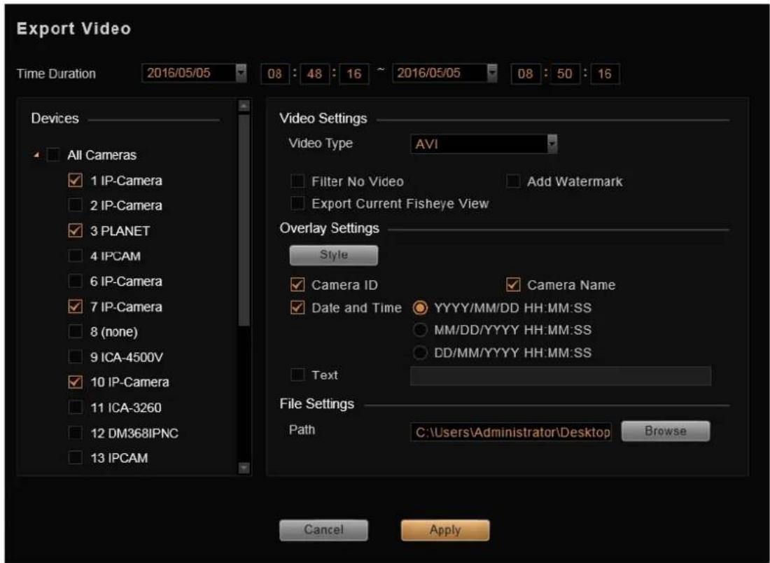
- Select the cameras. If more than one camera is selected, you will get multiple recordings.
- Set the time duration. The minimum duration is 10 seconds; maximum is 1 hour. (For individual recording, if the total size is over 2 GB, or the video encoder type, frame rate, resolution of this channel's stream once altered during the selected Time Duration, this file will be divided).
- For Video Settings, you can (1) choose the video format, (2) enable the "Filter no video" function to skip the video gaps, and (3) enable "Add Watermark" to embed a unique code in every frame of this exported video footage. If this channel is a fisheye camera, make sure you select the desired fisheye view by right-clicking the menu → "Fisheye Mode", and check "Export current fisheye view" here. The exported video will be displayed in the view mode you are seeing now; otherwise, the default fisheye view for exported video is Original View.
- Set the overlay text if needed. The maximum number of characters for Text is 40.
-
This exported video can be saved to your current client computer. Please choose the location. By default, the files will be saved to Desktop.
-
Click "Apply" to start file converting and exporting. The export process window will appear. In the Camera column displays the processed/total number of video clips of that camera. You may also observe the remaining processing time of each camera's video files.
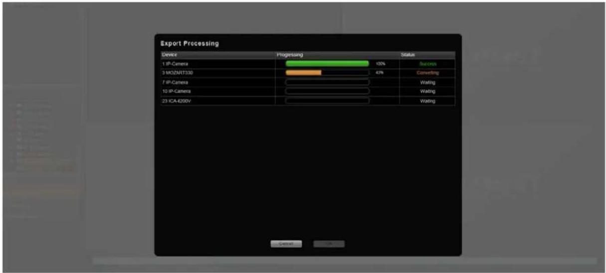
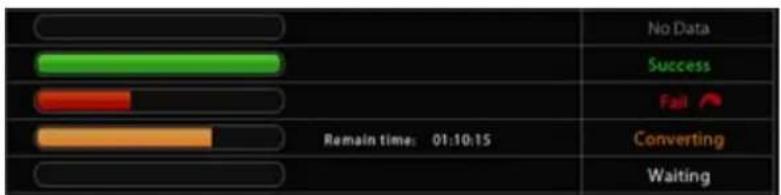
There are five types of process status: success, converting, waiting, no data and fail. It might happen that there is certain section in a recording that exists no video data; if the status shows "Fail", it may be that your disk drive does not have enough space for video files.
Please make some space and click 📄 again to re-execute this task.
- Once a channel is changed to any of the following fisheye modes: Dewarping, Panorama, Double Panorama, Panorama/Focus or Quad, the resolution of this live stream will become 1920x1080, so will the resolution of exported video clip.
- Certain fisheye camera view modes (e.g. Quad mode) display multiple regions in a single channel. When being exported, these regions will still be put together as a single video file.
Appendix A: Default Setting
| Default Login User Name for Windows | admin |
| Default Login Password for Windows | admin |
| Default Login User Name for NVR-E6480 Workstation | admin |
| Default Login Password for NVR-E6480 Workstation | admin |
Appendix B: NVR Performance
| NVR-E6480 (Live View) | ||||||||
| Camera | 10MP | 5MP | 4MP | 3MP | 2MP | 1.3MP | 1MP | VGA |
| 6fps | 15fps | 8fps | 15fps | 30fps | 30fps | 30fps | 30fps | |
| 1 6fps | 15fps 8fps | 15fps 30fps | 30fps 30fps | 30fps 30fps | ||||
| 2 | 1fps | 1fps | 1fps | 1fps | 1fps | 1fps | 30fps 30fps | |
| 3 | 1fps | 1fps | 1fps | 1fps | 1fps | 1fps | 30fps 30fps | |
| 4 | 1fps | 1fps | 1fps | 1fps | 1fps | 1fps | 1fps | 30fps |
| 5 | 1fps | 1fps | 1fps | 1fps | 1fps | 1fps | 1fps | 30fps |
| 6 | 1fps | 1fps | 1fps | 1fps | 1fps | 1fps | 1fps | 30fps |
| 7 | 1fps | 1fps | 1fps | 1fps | 1fps | 1fps | 1fps | 1fps |
| 8 | 1fps | 1fps | 1fps | 1fps | 1fps | 1fps | 1fps | 1fps |
| 9 | 1fps | 1fps | 1fps | 1fps | 1fps | 1fps | 1fps | 1fps |
| 10 | 1fps | 1fps | 1fps | 1fps | 1fps | 1fps | 1fps | 1fps |
| 11 | 1fps | 1fps | 1fps | 1fps | 1fps | 1fps | 1fps | 1fps |
| 12 | 1fps | 1fps | 1fps | 1fps | 1fps | 1fps | 1fps | 1fps |
| 13 | 1fps | 1fps | 1fps | 1fps | 1fps | 1fps | 1fps | 1fps |
| 14 | 1fps | 1fps | 1fps | 1fps | 1fps | 1fps | 1fps | 1fps |
| 15 | 1fps | 1fps | 1fps | 1fps | 1fps | 1fps | 1fps | 1fps |
| 16 | 1fps | 1fps | 1fps | 1fps | 1fps | 1fps | 1fps | 1fps |
| NVR-E6480 (Recording) | ||||||||
| Camera | 10MP | 5MP | 4MP | 3MP | 2MP | 1.3MP | 1MP | VGA |
| 6fps | 15fps | 8fps | 15fps | 30fps | 30fps | 30fps | 30fps | |
| 1-64 6fps | 15fps 8fps | 15fps 30fps | 30fps | 30fps | ||||

The above performance was tested on the following conditions:
| Codec | H.264 |
| Bitrate | 3Mbps |
| Remark | Disable "Decode-I" function in Display Performance Settings |
- 64-Channel Windows-based Network Video Recorder
- Copyright
- Federal Communication Commission Interference Statement
- FCC Caution
- Federal Communication Commission (FCC) Radiation Exposure Statement
- Safety
- CE Mark Warning
- WEEE Regulation
- Energy Saving Note of the Device
- Revision
- Table of Contents
- CHAPTER 1. PRODUCT DESCRIPTION ......6
- CHAPTER 2. HARDWARE INSTALLATION....15
- CHAPTER 3. LOG IN TO THE SYSTEM....20
- CHAPTER 4. NVR USER INTERFACE OVERVIEW....26
- CHAPTER 5. LIVE VIEW....31
- CHAPTER 6. MONITOR THE SYSTEM....41
- APPENDIX A: DEFAULT SETTING....76
- APPENDIX B: NVR PERFORMANCE....77
- ption Chapter 1. Product De
- Instant Playback
- Dual Stream Management
- Location Management with eMap
- Remote Access via Mobile App, Web Browser or CMS
- Large Storage Capacity
- x SATA hard disk drive
- Product Features
- Hardware
- Video & Audio
- Video Recording & Backup
- Network Service
- Easy Installation & Management
- Remote Access
- Packet Contents
- Physical Specifications
- ation Chapter 2. Hardware
- Rack Mounting
- Start Up
- stem Chapter 3. Log in to t
- Access via Internet Explorer Browser
- Login
- Access via NVR-E6480 Workstation
- Change User Profile
- rview Chapter 4. N'
- NVR Resident Tool Bars
- Tool Bar:
- NVR Main Screen
- Live View
- Playback
- Setup
- View Chapter 5. Live
- Select a View
- Select a Camera
- Camera List
- Remove a Channel
- Remove All Channels
- Add Bookmark
- TIP Full Screen
- Stretch/Un-stretch Channel
- Enable View Patrol
- stem Chapter 6. Monitor the
- Read System Alerts and Channel Status
- Channel Status
- The indicators
- •Right
- • Left
- Event Panel
- Instant Event Playback
- Pop-up Event Playback
- Hotspot Window
- Motion Region Indicator
- Live View Operations
- Show Mini Live View Windows on a Map
- Adjust Audio-in Volume
- Send Audio Signal
- Trigger Digital-out Device
- Watch Instant Playback of a Channel
- Manual Recording
- Take a Snapshot of Live Image
- Digital PTZ Operation
- Optical PTZ Operation
- Using Mouse Controls
- Navigate a Fisheye Camera Channel
- Change Fisheye Mode
- PTZ Operation
- back Chapter 7. Play
- Playback UI Introduction
- How to Do Playback
- Add Video Source
- Remove Unwanted Channels
- Search on Time Bar
- Display Event Types
- Playback Controls
- Digital Zoom on Channel View
- Explore Fisheye View
- Search by Time
- Search by Event Type
- Search by Video Analytics
- Motion
- Tamper
- To start,
- On Search Tool panel, click "Smart Search".
- View Search Results
- Take a Snapshot of the Playback View
- Export the Recordings
- sites:
- Define the Section of Exported Video on Time Bar
- Set the Export Video Settings
- Appendix B: NVR Performance
Brand : Planet
Model : NVR-E6480
Category : Video recorder