NVR-915 - Video recorder Planet - Free user manual and instructions
Find the device manual for free NVR-915 Planet in PDF.


| Product Type | Network Video Recorder (NVR) |
| Brand | Planet |
| Model | NVR-915 |
| Dimensions (W x D x H) | 380 x 270 x 50 mm (Desktop) |
| Weight | 2.5 kg |
| Power Supply | 100-240 V AC, 50/60 Hz, 60W |
| Number of Channels | 8 channels (IP cameras) |
| Video Compression | H.265/H.264 |
| Recording Resolution | Up to 4K (3840x2160) |
| Storage Capacity | Up to 2 SATA HDDs (10 TB each) |
| Network Interface | 2x Gigabit Ethernet RJ-45 |
| Remote Access | Via web browser, mobile app (iOS/Android) |
| Motion Detection | Yes, configurable zones and sensitivity |
| Playback | Simultaneous playback of multiple channels |
| Maintenance | Clean with dry cloth; avoid dust and moisture |
| Safety | Use only included power adapter; keep ventilation clear |
| Spare Parts & Repairability | Contact Planet support for authorized service |
| Operating Temperature | 0°C to 40°C |
Frequently Asked Questions - NVR-915 Planet
User questions about NVR-915 Planet
0 question about this device. Answer the ones you know or ask your own.
Ask a new question about this device
Download the instructions for your Video recorder in PDF format for free! Find your manual NVR-915 - Planet and take your electronic device back in hand. On this page are published all the documents necessary for the use of your device. NVR-915 by Planet.
USER MANUAL NVR-915 Planet
natural_image
Black PLNET Network Video Recorder device with ports and indicator lights (no visible text or symbols on body)9-Channel
Network Video Recorder
NVR-915

natural_image
Group of business professionals in a meeting around a laptop, engaged in discussion (no visible text or symbols)Copyright
Copyright © 2014 by PLANET Technology Corp. All rights reserved. No part of this publication may be reproduced, transmitted, transcribed, stored in a retrieval system, or translated into any language or computer language, in any form or by any means, electronic, mechanical, magnetic, optical, chemical, manual or otherwise, without the prior written permission of PLANET.
PLANET makes no representations or warranties, either expressed or implied, with respect to the contents hereof and specifically disclaims any warranties, merchantability or fitness for any particular purpose. Any software described in this manual is sold or licensed "as is". Should the programs prove defective following their purchase, the buyer (and not PLANET, its distributor, or its dealer) assumes the entire cost of all necessary servicing, repair, and any incidental or consequential damages resulting from any defect in the software. Further, PLANET reserves the right to revise this publication and to make changes from time to time in the contents hereof without obligation to notify any person of such revision or changes.
All brand and product names mentioned in this manual are trademarks and/or registered trademarks of their respective holders.
Federal Communication Commission Interference Statement
This equipment has been tested and found to comply with the limits for a Class B digital device, pursuant to Part 15 of FCC Rules. These limits are designed to provide reasonable protection against harmful interference in a residential installation. This equipment generates, uses, and can radiate radio frequency energy and, if not installed and used in accordance with the instructions, may cause harmful interference to radio communications. However, there is no guarantee that interference will not occur in a particular installation. If this equipment does cause harmful interference to radio or television reception, which can be determined by turning the equipment off and on, the user is encouraged to try to correct the interference by one or more of the following measures:
- Reorient or relocate the receiving antenna.
- Increase the separation between the equipment and receiver.
- Connect the equipment into an outlet on a circuit different from that to which the receiver is connected.
- Consult the dealer or an experienced radio technician for help.
FCC Caution
To assure continued compliance, for example, use only shielded interface cables when connecting to computer or peripheral devices. Any changes or modifications not expressly approved by the party responsible for compliance could void the user's authority to operate the equipment.
This device complies with Part 15 of the FCC Rules. Operation is subject to the Following two conditions: (1) This device may not cause harmful interference, and (2) this device must accept any interference received, including interference that may cause undesired operation.
Federal Communication Commission (FCC) Radiation Exposure Statement
This equipment complies with FCC radiation exposure set forth for an uncontrolled environment. In order to avoid the possibility of exceeding the FCC radio frequency exposure limits, human proximity to the antenna shall not be less than 20 cm (8 inches) during normal operation.
Safety
This equipment is designed with the utmost care for the safety of those who install and use it. However, special attention must be paid to the dangers of electric shock and static electricity when working with electrical equipment. All guidelines of this and of the computer manufacture must therefore be allowed at all times to ensure the safe use of the equipment.
CE Mark Warning
This is a Class B product. In a domestic environment, this product may cause radio interference, in which case the user may be required to take adequate measures.
WEEE Regulation

To avoid the potential effects on the environment and human health as a result of the presence of hazardous substances in electrical and electronic equipment, end users of electrical and electronic equipment should understand the meaning of the crossed-out wheeled bin symbol. Do not dispose of WEEE as unsorted municipal waste and have to collect such WEEE separately.
Energy Saving Note of the Device
This power required device does not support Stand by mode operation.
For energy saving, please remove the AC-plug to disconnect the device from the power circuit.
Without remove the AC-plug or switch off the device, the devices will still consuming power from the power circuit. In the view of Saving the Energy and reduce the unnecessary power consuming, it is strongly suggested to switch off or remove the DC-plug for the device if this device is not intended to be active.
Revision
User's Manual of PLANET 9-ch Network Video Recorder
Model: NVR-915
Rev: 1.0 (Jul, 2014)
Part No. EM-NVR-915_v1.0
Table of Contents
Chapter 1. Product Description....6
1.1 Product Features 6
1.2 System Requirements....7
1.3 Packet Contents 7
1.4 Specifications....7
1.5 Physical Specifications .... 10
Chapter 2. Hardware Installation....12
2.1 Accessories Check 12
2.2 Installation....12
Chapter 3. Connecting to the NVR .....15
3.1 Use Device Search Utility 15
3.2 Access NVR with its default IP address....18
Chapter 4. System....20
4.1 Main Console....20
4.2 System Information....20
4.3 Screen Division....20
4.4 Sub-screen Functions....21
Chapter 5. System Setting....23
5.1 Camera Setup....23
5.1.1 Audio Setting 23
5.1.2 Template Setting....24
5.1.3 Camera List 25
5.1.4 Camera Setup....25
5.1.5 Parameter Setting....26
5.1.6 Search Camera....27
5.2 Schedule Setting....27
5.3 Network Setting 29
5.3.1 Network 29
5.3.2 PPPoE....29
5.3.3 UPnP 30
5.3.4 UPnP Transversal....30
5.3.5 Server 30
5.3.6 DDNS 30
5.4. System Setting....31
5.4.1 Device Information....31
5.4.2 Date & Time Info....31
5.5.User Setting 32
5.6. Motion Detection Setting....33
5.7.Address Book Setting 34
5.8. Notification Setting....34
Chapter 6. System Management ....36
6.1. System Management....36
6.2. Disk Management....37
6.3. Snapshot....37
6.4. Event Snapshot 39
6.5. Samba Server....40
Chapter 7. Event Setting....41
7.1 Add a New Event....41
7.2 Modify Existing Event Schedule or Output Action....42
7.3 Delete Existing Event Schedule or Output Action....43
7.4 Event Action Type....43
Chapter 8. Log Viewer ....46
8.1 System Log....46
8.2 Event Log....47
8.3 Bitrate Log 48
Chapter 9. Playback....49
9.1 Search Recorded Video Files 49
9.2 Playback Control Buttons....50
9.3 Convert into AVI File....51
9.4 Backup Video File....51
Chapter 10.Web Remote Management ....52
10.1 Connection to NVR 52
10.2 Live View on Internet Explorer 53
10.3 System Information....54
10.4 Screen Division....54
10.5 Sub-screen Functions ....55
10.6 Playback on Internet Explorer....56
Chapter 1. Product Description
PLANET NVR-915 is a Linux-based standalone NVR, a new model of Network Video Recorder (NVR) series designed for IP surveillance system. Users can just turn on cameras and the NVR to easily protect their office and property under the Ethernet / IP networks. The recorded video files can be saved on the NVR and thus, an additional PC for file storage is not necessary, bringing users a secure surveillance system at a lower total cost of ownership.
The NVR-915 provides powerful central surveillance management capability with its bundled Central Management Software (CMS). One NVR-915 can manage up to 9 IP cameras via a connected IP network. With the bundled CMS, the NVR system is expandable for multi-sites management of up to 256 surveillance channels simultaneously. With the NVR-915, users can view remote surveillance in real time and play back recorded videos via the bundled CMS software or the web browser. The NVR also helps the administrators to monitor the surveillance system more efficiently by providing multi-monitors.
The NVR-915 not only supports PLANET IP cameras but also is compatible with most of major IP camera brands with ONVIF in the market. Furthermore, the NVR-915 can automatically search and find the available cameras in the network and provide smart setup wizard program, so it greatly reduces users' effort when setting up the system.
The NVR-915 is suitable to fit in various network environments. Besides its small-scale applications for retail stores and SMBs, the NVR-915 offers 2 SATA HDDs supporting capacity up to 8TB and is ideal for large-scale surveillance premises, such as banks, enterprises, transportation, campuses, etc.
1.1 Product Features
Hardware
■ Linux-embedded, highly-reliable standalone NVR
■ Supports Gigabit Ethernet port
■ Supports VGA / HDMI dual local display
■ Supports 3.5" SATA III x 2 HDDs
■ Supports e-SATA
Video / Audio
■ Simultaneous recording and live view streams
■ 9 channels input of IP cameras
■ Supports H.264 compression
■ Video resolution up to 5 mega-pixel (2560 x 1920)
■ Supports throughput up to 80Mbps
■ 2-way audio (G.711, G.726)
Video Recording / Backup
■ Scheduled recording of 9 IP cameras simultaneously
■ Samba path supported
■ Supports 2 SATA HDDs, up to 4TB per HDD
1 x e-SATA
■ Exports recorded video file in AVI format to USB device or local storage
■ Instant Event Notification and recording
Network Service
■ Easy access with PLANET Dynamic DNS and built-in NTP Server
■ Supports PPPoE / DHCP / Static network connection
■ Supports low bit-rate connection for remote access
Easy Installation & Management
■ ONVIF compliant for interoperability
■ Supports multiple languages
■ Automatically discovered by management software
■ Web-based and management utility for easy configuration
■ Up to 256 channels management through central management software
■ Supports USB mouse and joystick (PTZ)*
■ Supports mobile phone remote view
*The remote control and joystick are optional
1.2 System Requirements
The following are the minimum system requirements for the system to operate Network Video Recorder (NVR):
| Operating System | Microsoft® Windows® 2000 Professional, Windows® XP Professional (32 bit) or Windows® Server 2003 (32 bit) Browser Microsoft Internet Explorer 7 or above |
| CPU | Minimum Intel® Pentium® 4 2.4 GHz or higher (Dual Core is recommended) RAM Minimum 1 GB of RAM, 2GB or above is recommended |
| Network | Minimum 10/100 Ethernet (Gigabit Ethernet is recommended) |
| Graphics Adapter | AGP or PCI-Express, minimum 1024 x 768, 16 bit colors. (We highly recommend to work above the 1024 x 768 resolution to get the full experience of the software) |

Make sure your display DPI setting is set to default at 96DPI
To set DPI value, right-click on desktop, choose "Settings" tab >> "Advanced" >> "General"
1.3 Packet Contents
1 x NVR
1 x Power Adapter
2 x SATA Data Cord
2 x SATA Power Cord
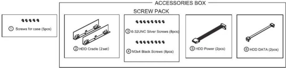
16 x Screw
2 x HDD Cradle
1 x CD-ROM
1 x Quick Installation Guide
1.4 Specifications
| Product | NVR-915 |
| Hardware | |
| Ethernet 1 x RJ-45, 10/100 | 1000Base-T |
| USB Interface 2 x USB 2.0 | for backup device and mouse |
| Video Interface VGA / HDMI video interface | |
| Audio Interface | 1 x Mic-in (phone jack 3.5mm), 1 x Audio-out (phone jack 3.5mm) |
| Storage Device 2 x 3.5" SATA III hard disk connectors, 1 x e-SATA connector | |
| LED Power, HDD, LAN, REC, Event, Alarm, Camera, DI/DO | |
| Button Reset | |
| Buzzer 1 x Buzzer | |
| DI/DO 4 x Digital in, 4 x Digital out | |
| Camera | |
| Max. Channels 9-channel IP cameras | |
| Add camera Manual / Auto Search / Auto setup | |
| Video | |
| Compression | H.264 |
| Resolution 5M / 3M / Full HD / SXGA / VGA / QVGA | |
| Max. live video frame rate (Local Display) | 480fps@D130360fps@720P30120fps@1080P3020fps@5M15Max. 5MP/channel |
| Max. throughput 48Mbps | |
| Snapshot | Preview snapshot in HDD or removable deviceSearch event snapshotBackup to USB device |
| Audio | |
| Audio Type 2-way | |
| Audio format | G.711, G.726 |
| Live view | |
| Display Mode | Live View / Playback / Full Screen |
| Split Screen | 1 / 4 / 6 / 9 / Full Screen |
| Full Screen | 1 / 4 / 6 / 9 |
| PTZ Support | Preset / Tour / Auto pan / Iris / Focus / Speed, and joystick |
| Playback | |
| Split Screen | 1 / 4 / 6 / 9 / Full Screen |
| Search Mode | Simple / Graphical / Event |
| Play Method | Play / Reverse / Pause / Seek / Pre I-frame / Next Frame Search by time or event |
| Record | |
| Recording Mode | Schedule recording each cameraRound the clock / Motion record modes / DI detection / Event TriggerPre-alarm / Post-alarm configurationAuto recycle |
| Monitor | |
| Dual Monitor | Display same contents, depending on max. channels |
| Monitor Resolutions | 1920x1080, 1440x900, 1366x768, 1280x1024, 1024x768 |
| Network and Configuration | |
| Network Service Fix IP / DH | HCP / PPPOE / DIPS Report / UPNP / DDNS |
| Notification SMTP / HTTP | / FTP / TCP |
| Triggers and Event | |
| Event type | ● Motion Alarm● Disconnect Alarm● Audio Detection● Digital Input● Schedule Trigger● HDD Error |
| Event Action | ● Display on screen● DO● Buzzer alarm● Snapshot● Recording● Mail● FTP● TCP● HTTP |
| Management | |
| Number of Groups 2 (Administrator / User) | |
| Privileges Live View / Playback / Record / Setting / PTZ / Two Way Audio | |
| User Interface | ● Graphic local user interface (Operated by mouse)*● Web browser (Internet Explorer 7 or above)● CMS Utility |
| Log Type | System / Event / Bit-rate |
| Software Utility | Search utility / Mobile app / CMS |
| Environment | |
| Power | 12V DC/4.16A |
| Consumption | 8W (without HDD) |
| Operating Temperature | 0~40 degrees C |
| Storage Temperature | -40~70 degrees C |
| Humidity | 0~85% (non-condensing) |
| Weight | 1455g |
| Dimensions (W x D x H) | 330 x 252 x 57 mm |
1.5 Physical Specifications
Front Panel
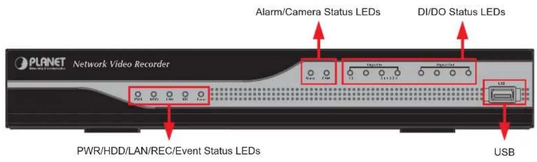
| LEDs Color | Description | |
| PWR | Green | LED on when system is ready |
| HDD | Green | LED on when HDD is reading or writing |
| LAN Blue LED blinking when network is connected | ||
| REC Green LED on when record schedule is on | ||
| Event Green LED on when event detection schedule is on | ||
| Alarm Amber LED on when hard disk writes error | ||
| CAM Amber LED on when system has camera disconnected | ||
| Digital In (1~4) | Amber | LED on when digital input X is closed |
| Digital Out (1~4) | Blue LED | on when digital output X is closed |
Rear Panel
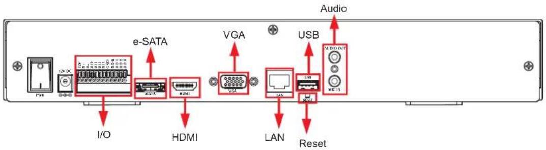
| Connector | Description |
| USB | Connect your mouse and USB flash disk for local display control and backup |
| Reset Press and hold reset | set button to factory default |
| HDMI | HDMI output |
| VGA VGA output | |
| e-SATA | External e-SATA HDD |
| LAN 10/100/1000Mbps network. | |
| I/O DI x 4 / DO x 4 | |
| Audio Audio out / Mic in | |
Chapter 2. Hardware Installation
2.1 Accessories Check
2.2 Installation
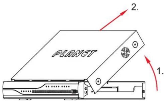
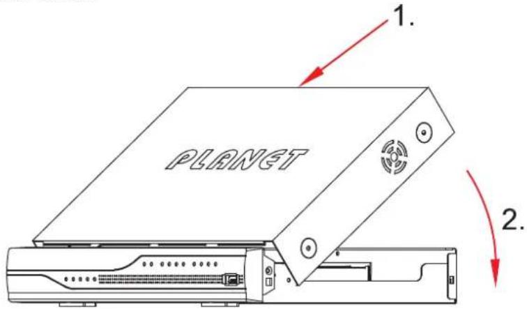
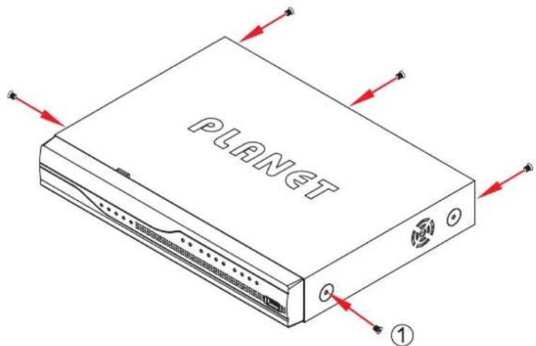
- Remove all screws on the box.
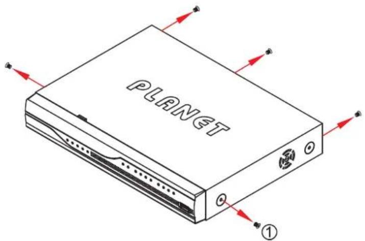
- Lift up and remove the cover.
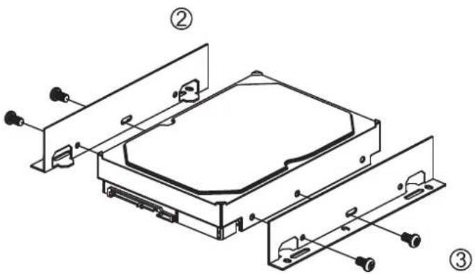
- Assemble the hard disk cradles with the silver screws.
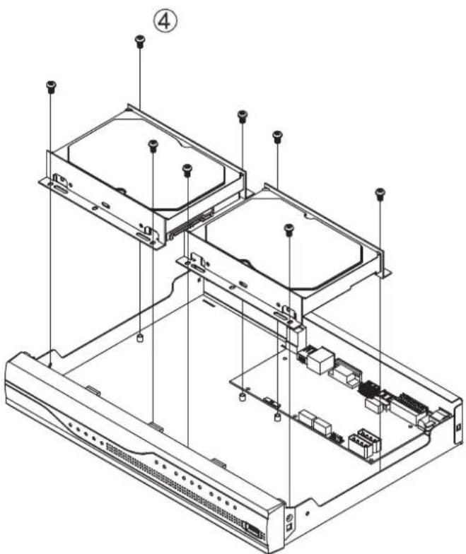
- Install the hard disks in the case with the black screws.
natural_image
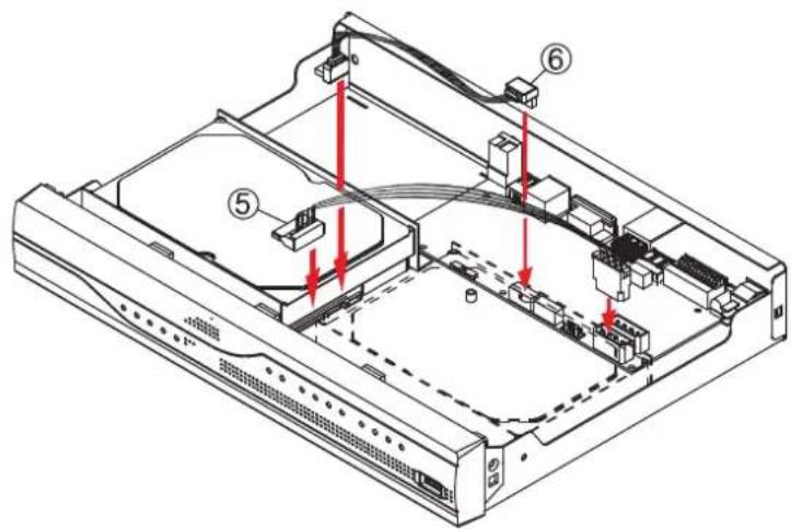
Isometric line drawing of a computer chassis with labeled components (no text or symbols present)- Connect the SATA data cable and SATA power cable between hard disk and main board.
- Put the cover back.
- Assemble all the screws back to the box.
Chapter 3. Connecting to the NVR
There are various ways you can connect to the NVR and below are the suggested methods for different network setups:
The NVR is placed in a network with a DHCP server: Connect to the NVR by using "PLANET IP Wizard II" Utility.
The NVR is placed in a network without DHCP server (or you are connecting to it directly): Access NVR with its default IP (192.168.0.20).
3.1 Use Device Search Utility
If the NVR is placed in a corporate network or a local area network where a DHCP server is already presented, please install the "PLANET IP Wizard II" utility from the bundled CD disk.
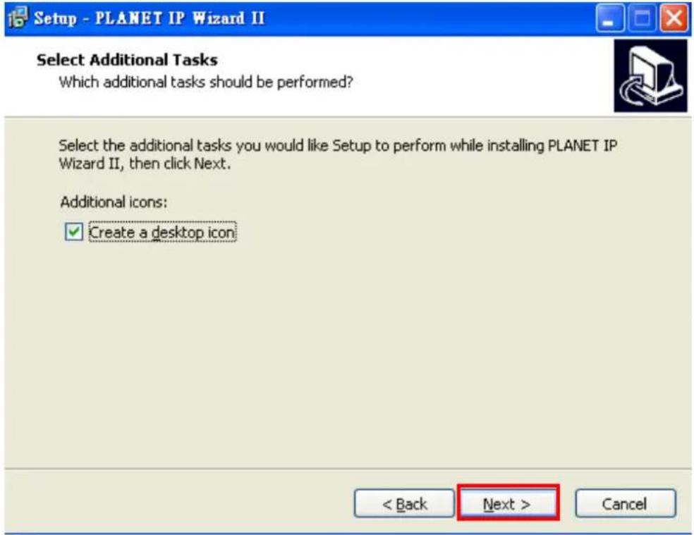
To begin, launch the "PLANET IP Wizard II" utility from the CD and proceed with the installation.
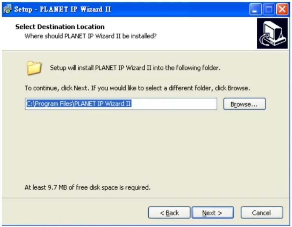
Please click "Next" to continue.
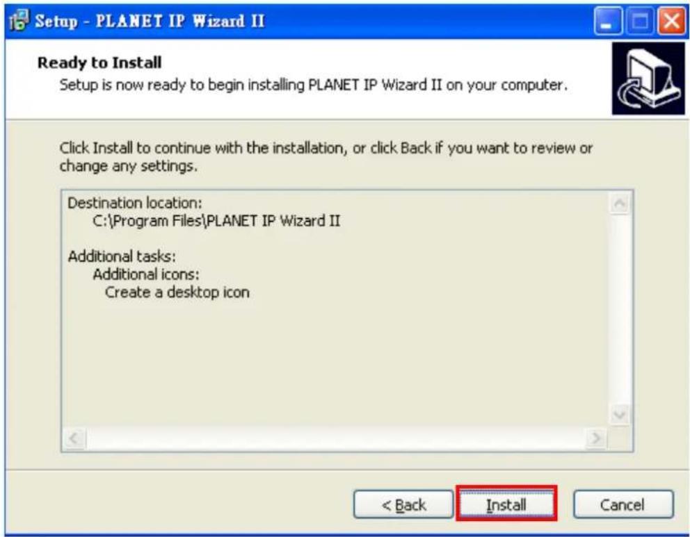
Please click "Install" to start the installation.
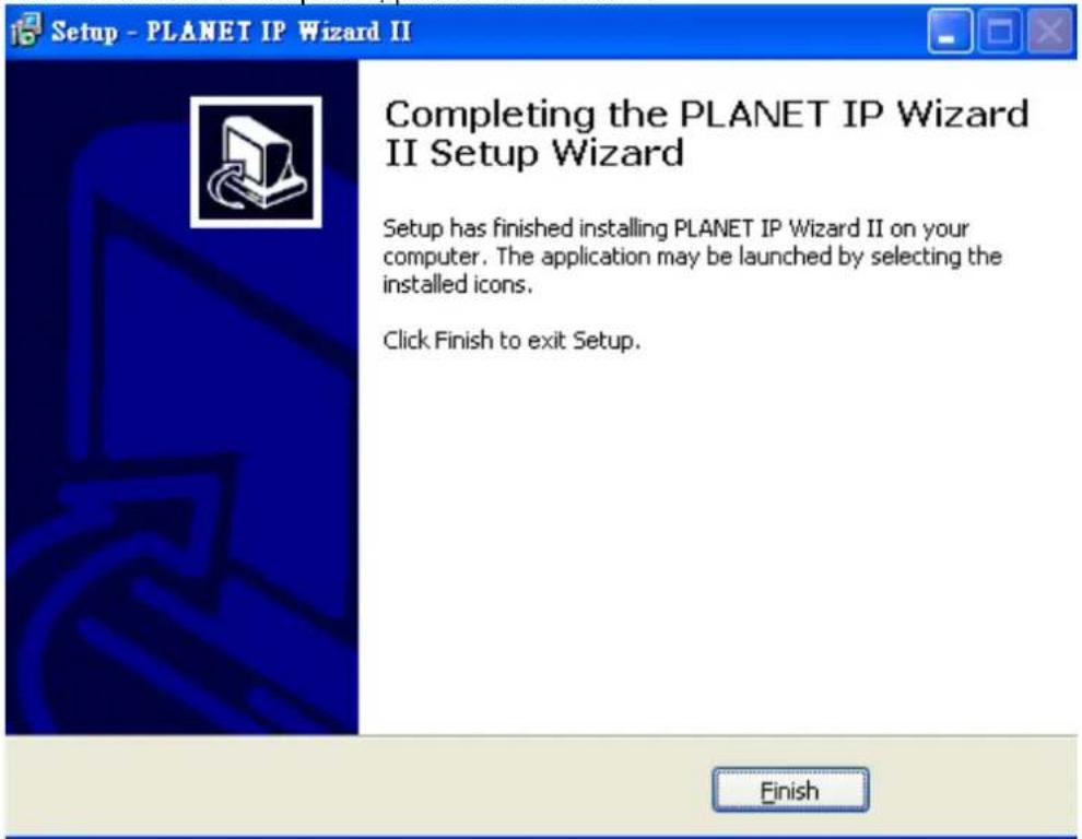
Once the installation is completed, please click "Finish".
Please go to Start => Programs => PLANET IP Wizard II => PLANET IP Wizard II to run the search tool. Then you will see the utility start searching the network.
The NVR should be located and its IP address should be displayed: Double-click on it and the program should automatically access the NVR's web administration page from your default browser.
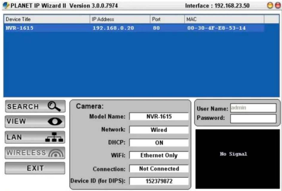
You may change NVR's IP address by clicking on the button highlighted below.
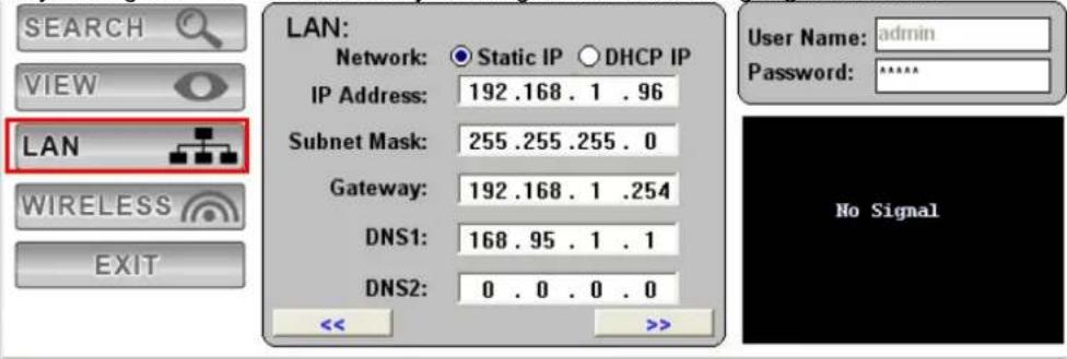
You will be prompted for the NVR's login information before proceeding to change device's IP address.
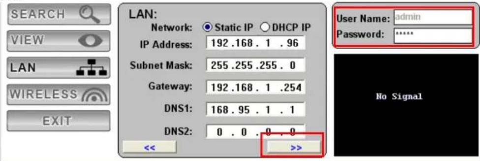
Enter
3.2 Access NVR with its default IP address
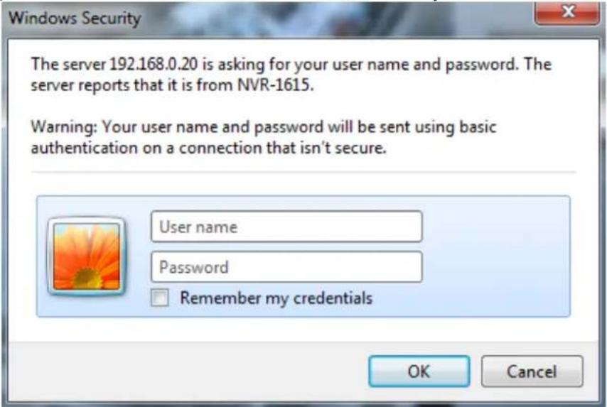
The NVR comes with a pre-configured static IP address "192.168.0.20". However, it is only used when there is no DHCP server presented in the network. Connect the NVR and PC to your switch or hub, or connect the PC directly to the NVR using a crossover CAT5 Ethernet cable.
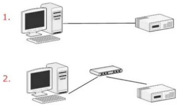
The PC that is connected directly to the NVR (or within the same local area network) should receive an IP from it. Simply access the NVR from your Web browser with NVR default IP address.
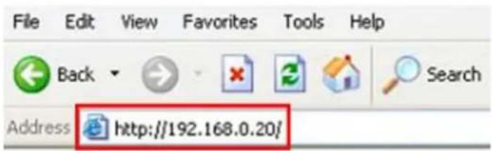
You should be prompted for the user name and password. Enter its default username "admin" and password "admin" and then click "OK" to enter the system.
Chapter 4. System
4.1 Main Console
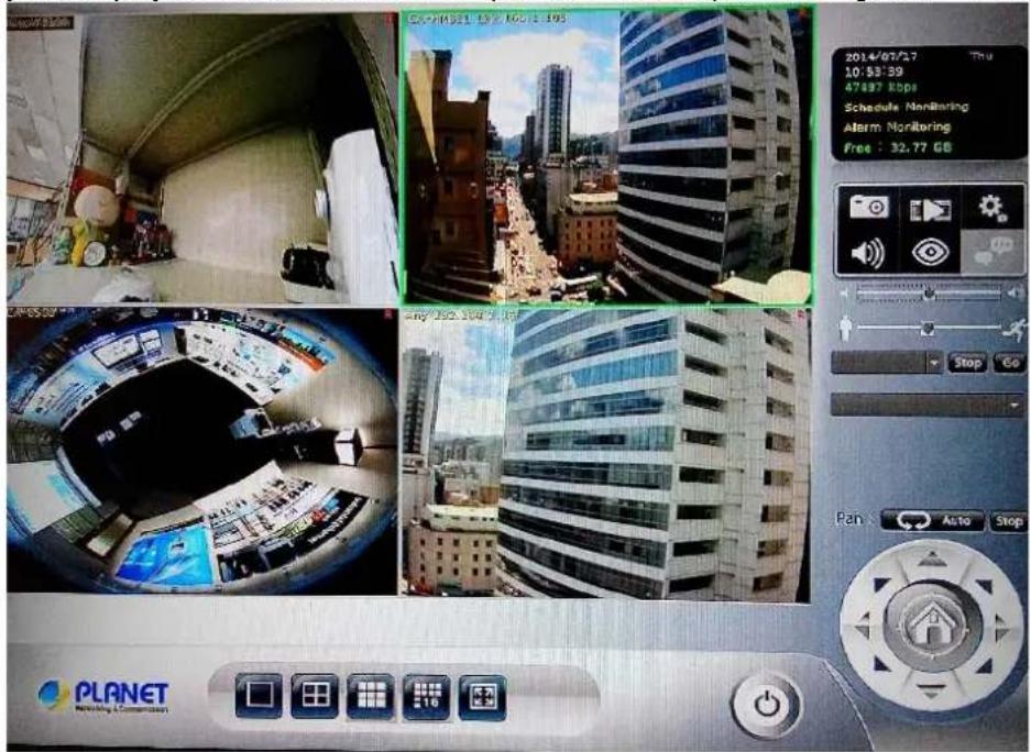
This is the main control panel of the system providing live stream preview, system setup, two-way audio, playback, volume control, snapshot, start or stop monitoring, and PTZ controls.
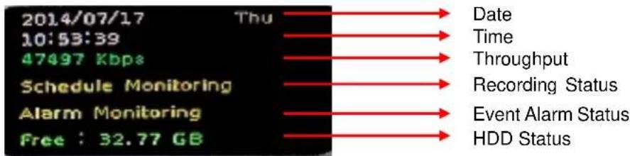
4.2 System Information
4.3 Screen Division
Assign the preview screen to the expected layout division by clicking these buttons.

Switch to 1 division

Switch to 4 division

Switch to 9 division

Switch to Full screen, and click mouse right button to cancel Full Screen.

Logout / firmware version display
4.4 Sub-screen Functions
| Digital Zoom | Sub-screen window supported digital zoom; operating steps are as follows:1. Click on preview image for switch current focus channel.2. Scroll the mouse wheel; forward for digital zoom-in, and backward for zoom-out.3. Switch division mode will reset digital zoom status to default. | |
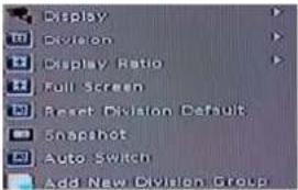 Popup Menu Popup Menu | Click right button of mouse and select an option from the popup menu.1. Change current channel display camera.2. Change current division mode.3. Switch to current channel display ratio mode.4. Switch to Full Screen mode / Cancel Full Screen mode.5. Reset all channels to default camera list.6. Snapshot current display.7. Enable / Disable auto switch. | |
 Setting Setting | Click it to set up system and view log | |
 Playback Playback | Click it to go to “Playback” page to search and display needed video | |
 Snapshot Snapshot | Click it to take a snapshot to the HDD; you can manage snapshots on “snapshot” page under system management | |
 Audio Volume Control Audio Volume Control | Click it to switch between normal and mute | |
 Schedule Monitoring Schedule Monitoring | Click it to enable or disable scheduled monitoring;the recording will be stopped if it is disabled | |
 Two-way Audio Two-way Audio | Click it to start or stop two-way audio of selected channel | |
 PTZ Control PTZ Control | Move PTZ camera direction by clicking direction buttons | |
PTZ Control Home

Click it to make camera return to home position
Tour
Move the thumb to control speed
Select a tour setting from combo box and click "go" button to start tour, click "Stop" button to stop tour
Preset
Select a preset position from combo box and camera will move to preset position after clicking

IRIS
Adjust camera's IRIS setting, or set it to auto

Focus
Adjust camera's focus setting, or set it to auto

Zoom
Zoom-in or zoom-out focus

PAN
Start camera auto pan or stop
Chapter 5. System Setting
Click setup button and select "System Setting" from pop-up menu to approach system setting dialog.
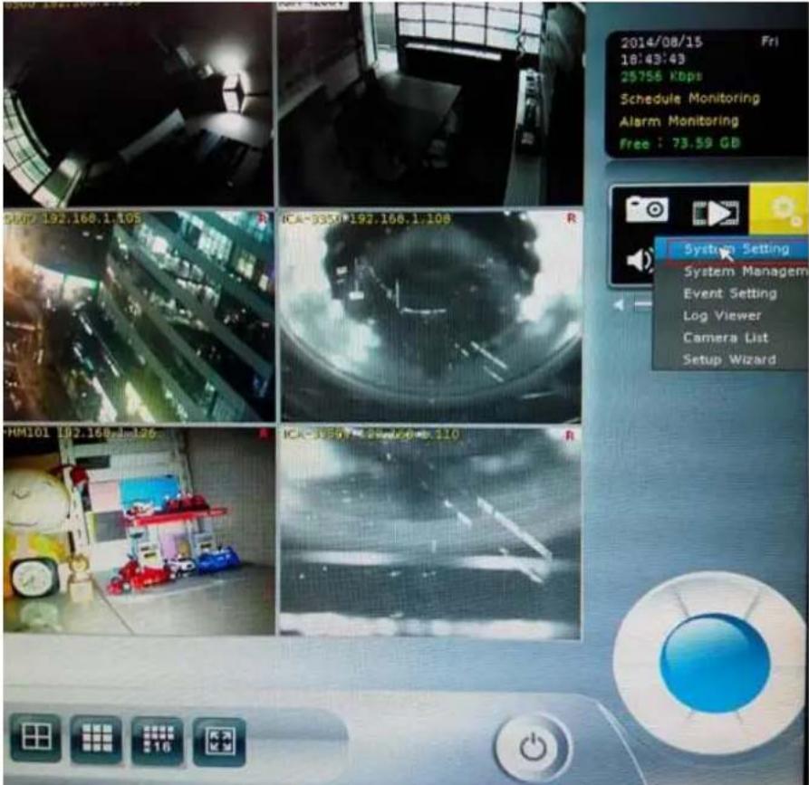
5.1 Camera Setup
5.1.1 Audio Setting
Click the "Auto Setting" button for adding cameras to system automatically, and maximum number of cameras depends on NVR's model.
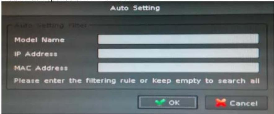
After clicking the button, system will show the fuzzy search filter dialog. You could input the search filter with model name, IP address or MAC address, or you could keep them empty to search all cameras.
Auto setting could insert Intranet's cameras even these cameras are located behind several switch hubs. Besides, you could directly insert cameras on NVR's switch hub and then click "Auto Setting" button to add them to system. Through "Auto Setting" function, you do not need to key-in any network IP address or sub-mask parameter. All you need to do is click "Auto Setting" button to finish the job of inserting IP camera.
5.1.2 Template Setting
When you use "Auto Setting" or add a new camera, system will read the camera template from "Template Setting" to fill out the camera parameter.
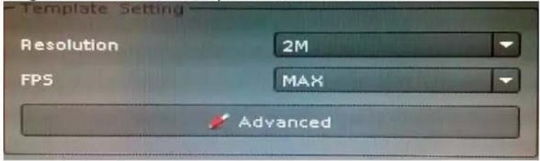
After the template has been confirmed, you will no longer need to set up parameter of camera again in most cases. You could set up the quick template from camera setting page and only need to set the camera's resolution and frames per second. If you need to set up more details in template, please click the "Advanced" button to approach the template setting dialog.
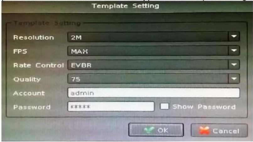
Resolution: The new camera will try to fit the selected resolution. When you select "Max", the camera will adopt maximum resolution. If you select another resolution, the system will choose a resolution for the camera.
FPS: Set up frames per second for camera; system will try to set a near or equal FPS to camera.
Rate Control: Set up the rate control algorithm of new camera.
Quality: If you select EVBR for new cameras, you could set up the then VBR quality here.
Account: Set up the default login user account of camera.
Password: Set up the default login password of camera.
5.1.3 Camera List
List all inserted IP camera model names and IP addresses. It is able to display detailed information and live streaming video by clicking the row of camera.

Check the box to make the camera available for video streaming; otherwise, the camera will be disabled if the check box is empty.
Switch Camera sequential
Click right button of mouse on the camera, and select another camera in the popup menu. System will switch to these two camera's settings.
Quick Setup
- Select a camera
-
Click "Quick Setup" button.
-
Select an action:
Copy to:
Copy selected camera's settings to all channel or single channel
Switch To:
Switch selected camera and target camera sequential position.
Remove all:
Remove all camera settings.
5.1.4 Camera Setup
Key-in or modify camera information here.
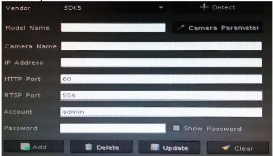
Vendor: You may select camera vendor or use ONVIF protocol for camera connection.
Detect: Check camera available and receive camera model name.
Camera Name: Key-in camera name.
IP Address: Key-in camera's IP address.
HTTP Port: Set up camera's HTTP port, default is 80.
RTSP Port: Set up camera's RTSP port for TCP streaming, default is 554.
Account: Set up the login user name of camera.
Password: Set up the login password of camera.
5.1.5 Parameter Setting
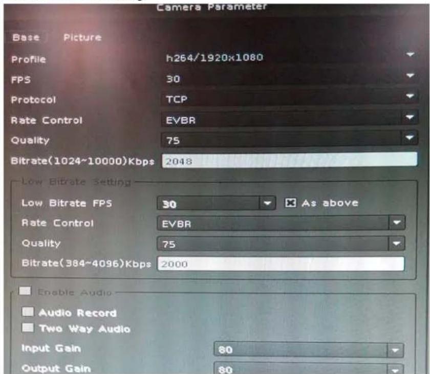
Profile: Select video codec and resolution for live viewing and recording.
FPS: Select FPS for live viewing and recording.
Protocol: Select protocol HTTP / TCP and UDP.
Rate Control: Select EVBR or CBR for better video performance.
Quality: Select video quality by numbers.
Enable Audio: You have to enable audio for two-way audio function.
Audio Recording: Enable it for audio recording.
Two-way Audio: Enable it for Two-way Audio function.
Input Gain: Adjust the gain to reduce the input audio noise.
Output Gain: Adjust the gain to reduce the output audio noise.

The parameter dialogs are different for each vendor. It depends on camera's capability.
Add Camera:
- Click "Search" button and wait for search job to finish.
- Select a camera on search result list.
- Preview live streaming video on preview window to confirm current camera.
- Click "Add" button to add selected camera into system.
Delete Camera:
- Select a camera from installed camera list.
- Click "Delete" button to remove selected camera from list.
Update Camera setting:
- Select a camera from installed camera list.
- Modify camera's setting at each setting fields.
- Click "Update" button to save modified result.

Updated setting will write to disk after clicking "OK" on the bottom of the page. If you click "Cancel" button to leave setting page, system will ignore all your modified settings.
Clear button: Clear all setting fields.
5.1.6 Search Camera
Click "Search" button and system will list all cameras that can be searched in "Search List". You can click on each row to preview live video streaming. In addition, you can click on the header column for sorting the current row data.
| Vendor | Model Name | Camera Name | IP Address | MAC Address | HTTP Port |
| SDK3 | ICA-HM126 | Planet BOX IP Camera | 192.168.0.55 | 00:30:4F:08:C6:… | 80 |
| SDK6 | ICA-4210P | ICA-4210P | 192.168.1.14 | 00:30:4F:B4:BE:FB | 80 |
| SDK6 | ICA-8350 | ICA-8350 | 192.168.1.127 | 00:30:4F:A8:64:EA | 8090 |
| SDK6 | ICA-1200 | ICA-1200 | 192.168.1.119 | 00:30:4F:A2:6C:FE | 8088 |
| SDK1 | ICA-3550V | ICA-3550V | 192.168.1.2 | 00:30:4F:AE:A2:… | 80 |
| SDK1 | ICA-3250V | ICA-3250V | 192.168.1.23 | 00:30:4F:B4:69:94 | 80 |
5.2 Schedule Setting
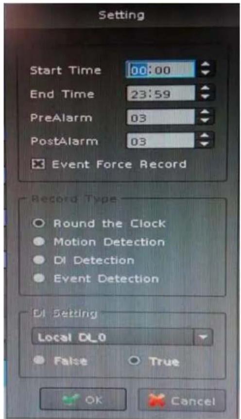
Schedule setting allows you to set up different times for recording. You may define multiple recording types for each day or within 24 hours.
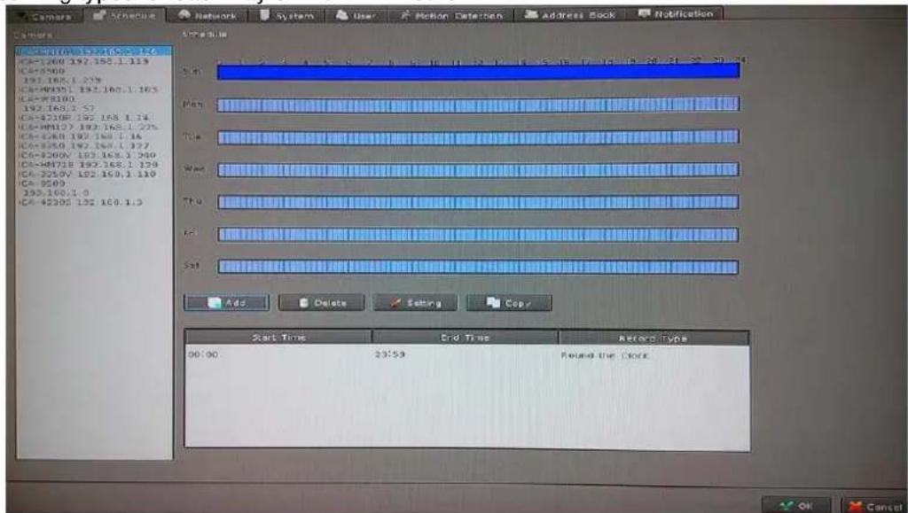
The step to configure recording schedule
Select a camera: Select a camera for schedule configuration.
Select a weekday: Select a weekday bar; system will list time periods with this weekday.
Add / Configure: Select the time period and type of recording.
Delete: Delete the preset schedule.
Copy: Copy selected schedule to all weekdays.
5.3 Network Setting
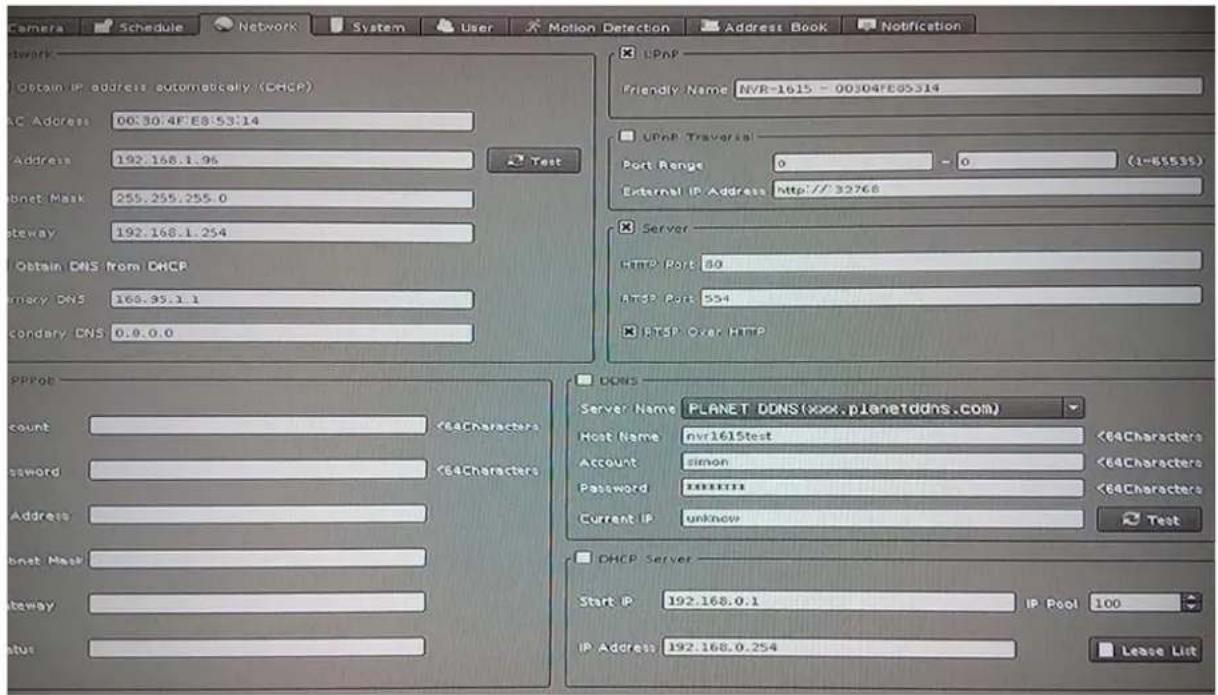
5.3.1 Network
DHCP Setting: Check the "Obtain IP address automatically (DHCP)" to get IP address from DHCP server automatically.
MAC Address: Display MAC address of this NVR.
IP Address: Input the fixed IP address If you have disabled the DHCP function, and then click "Test" button to detect IP conflict.
Subnet Mask: User defines.
Gateway: User defines.
Obtain DNS from DHCP: User defines.
Primary DNS: User defines.
Secondary DNS: User defines.
DNS Setting: Check "Obtain DNS from DHCP" to get DNS setting from DHCP server. It only works on DHCP when enabled. If "Obtain DNS from DHCP" is disabled, you could key-in DNS server IP in the text box.
5.3.2 PPPoE
Enable / Disable: Select the radio boxes to enable or disable PPPOE function.
Account: Key-in login user name of PPPOE server.
Password: Key-in login password of PPPOE server.
IP Address: Display current IP address which is assigned by PPPOE server.
Subnet Mask: Display current subnet mask which is assigned by PPPOE server.
Gateway: Display current gateway which is assigned by PPPOE server.
Status: Display PPPOE status.
5.3.3 UPnP
Friendly Name: Display UPnP friend name on network
5.3.4 UPnP Transversal
Enable UPnP Traversal to auto-request port mapping with router, and define maximum and minimum port value here.
Port Range: User defines.
External IP Address: User defines.
5.3.5 Server
Enable server option to start HTTP and RTSP server. When remote service is started, user is able to connect remote service via IE browser.
HTTP Port: Set up HTTP service port here. The default setting is 80.
RTSP Port: Set up RTSP service port here. The default setting is 554.
RTSP over HTTP: Enable RTSP over HTTP function and the remote live streaming will use HTTP protocol and HTTP port.
5.3.6 DDNS
The NVR-915 provides PLANET DDNS function to allow you to map a domain name to the dynamic IP address of a network device.
Sever Name: Select a DDNS server (e.g. PLANET DDNS).
Host Name: Key-in DDNS domain name.
Account: Key-in account of DDNS service.
Password: Key-in password of DDNS service.
Current IP: Click "Test" button to connect DDNS service and system will display current public IP address.
5.4. System Setting
5.4.1 Device Information
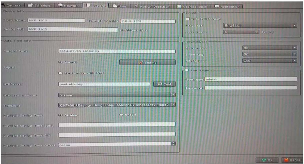
The "Device Information" provides the general information of the device such as firmware version and model name.
Model Name: Display model name.
Device Title: Key-in device title here.
Software Version: Display current firmware version
5.4.2 Date & Time Info
Current Time: Display current time.
Server Date & Time: Display current system date-time.
Adjust:
Manual:
Click setting to approach date-time setting dialog and select current date and time now; click "OK" to change system time or click "Cancel" button to abort configuration.
Synchronize with NTP (default):
Enable synchronize date-time with NTP service.
NTP Server: Key-in NTP server IP or domain name. If you use the domain name to connect NTP server, the DNS service must be enabled.
NTP Sync Interval: Select time period to synchronize with NTP service.
Time Zone: Select the time zone of NVR location.
Daylight Saving: Enable or disable daylight saving mode.
Daylight Saving Start Time: Configure daylight saving start time; it works with daylight saving mode when enabled.
Daylight Saving End Time: Configure daylight saving end time; it works with daylight saving mode when enabled.
Daylight Saving Offset: Configure daylight saving offset time with current time; it works with daylight saving mode when enabled.
Auto Login: Enable auto login mode to login with defined user name and password when system boots up.
User: Key-in auto login user name.
Password: Key-in auto login password.
System Setting: Enable "Auto full screen" to switch to full screen mode when system boots up.
-
Change display language from language combo box.
-
Adjust auto switch interval seconds.
DIPS: Display device DIPS ID. Click "Test" button for test connection with DIPS server.
5.5. User Setting
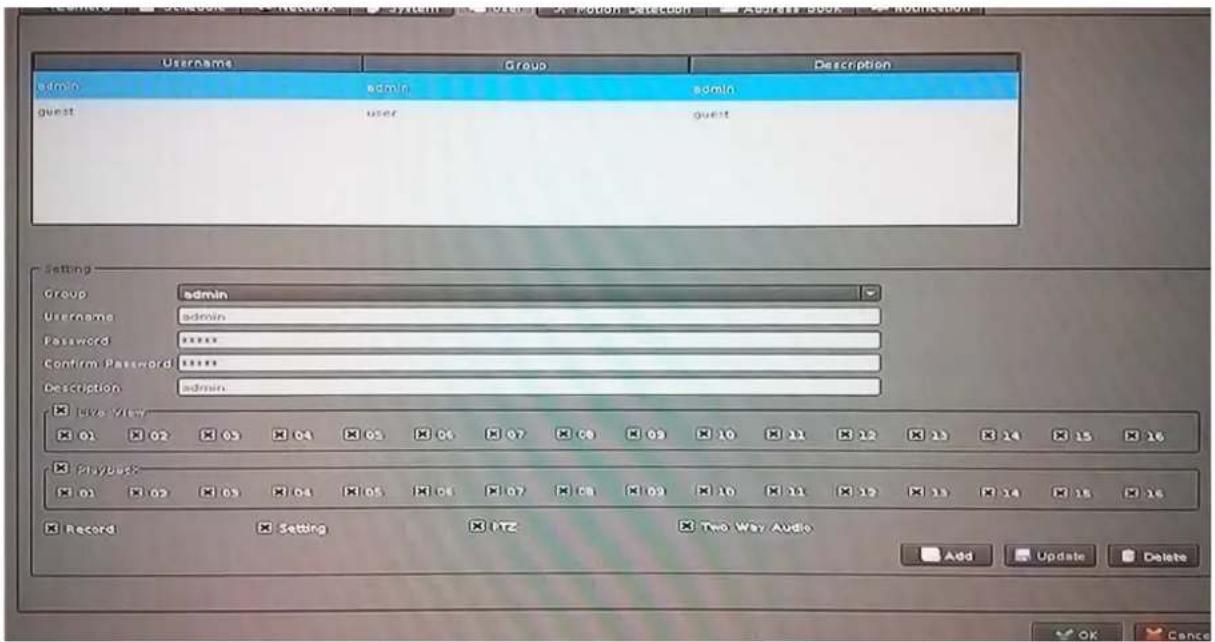
You may manage all user accounts or groups for different functions to access cameras.
Group: Select user's login group.
Username: Set up username for account.
Password: Set up password for account.
Confirm Password: Confirm the password is correct.
Description: Describe the user or group.
Live Viewing: Define the access permission for each user to have live viewing.
Playback: Define the access permission for each user to play back camera.
Record: Define user permission for recording.
Setting: Define user permission for system setting.
PTZ: Define user permission for PTZ controls.
Two-way Audio: Define user permission for two-way audio.
Add: Click to add user after keying-in the user information.
Modify: Modify the user information and permissions.
Delete: Delete selected user account.
5.6. Motion Detection Setting
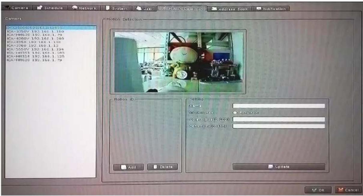
You may set up to 10 regions of each camera for motion detection setting.
Select a camera: Click on camera list and select a camera to set up motion detection.
Add new motion detection: Click "Add" button to insert new motion window and then the new window will appear on the left-upper corner.
Enable motion window: Check the window name to enable motion detection.
Modify motion detection area: Move mouse cursor to motion window border, and drag cursor to resize motion window. Drag mouse cursor on motion window to re-position of motion window.
Remove motion window: Click on motion window or window's name to set up focus window and then click "Delete" button to remove it.
Modify motion parameter: Click on motion window or window's name to set up focus window and then edit its motion parameters. You must click "Update" button to save modified values, otherwise the settings will be lost.
Name: Key-in motion window's name.
Include / Exclude: Include indicates system will detect motion inside of window area. Exclude indicates system will detect motion outside of window area.
Object Size: Set up motion detection object size whose value is between 0 and 100. The larger value indicates the object is bigger in the defined detection area.
Sensitivity: Set up motion detection sensitivity whose value is between 0 and 100. The larger value indicates the motion detection is more sensitive.
5.7. Address Book Setting
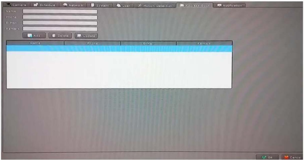
Add e-mail and other information to address book for sending e-mail alert.
Key-in the personal e-mail account information and then click on "Add" to add the information to the address book; you may also click on "Modify" to change the information or "Delete" to remove the account from the list.
5.8. Notification Setting
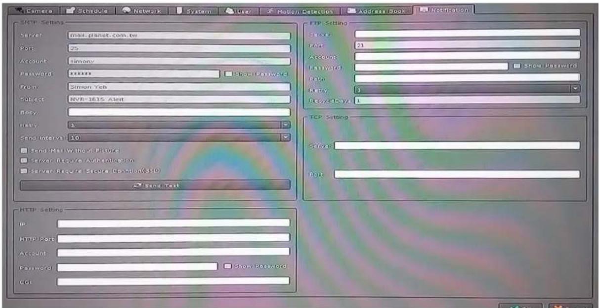
You may set up the notification to receive e-mails, send file to FTP server or HTTP CGI when the event is triggered.
SMTP Settings
| SMTP Server | SMTP sever IP or domain name. |
| SMTP Port | SMTP service port number |
| User Name | Login SMTP server user ID |
| Password | Login SMTP server Password |
| From | E-mail sender's name |
| Subject | Mail's subject |
| Body | Mail's body content |
| Retry | Retry the number of times when mail fails to send out |
| Send Interval | Set the interval of each time when mail is sent out |
| Send without picture | Do not attach picture with notification mail |
| Server Required Authentication | The e-mail server needs Authentication |
| Server Required Secure Connection | The e-mail server needs SSL connection |
| Send Test Button | Send out a test mail to check whether Server information is correct or not |
HTTP Setting
| HTTP IP | HTTP server's IP or domain name |
| HTTP Port | HTTP server's service port |
| HTTP User Name | Login HTTP server's user account |
| HTTP Password | Login HTTP server's password |
| HTTP CGI | HTTP server receive notification CGI path |
FTP Setting
| FTP Server | FTP server IP or domain name |
| FTP Port | FTP server service port |
| User Name | Login FTP server account |
| Password | Login FTP server password |
| Path | Upload picture or video path |
| Retry | Retry the number of times when upload fails |
| Recycle Days | Keep uploading failed picture or video in days |
TCP Setting
| TCP Server | TCP server IP or domain name. |
| TCP Port | TCP service port number. |
Chapter 6. System Management
The system management is for you to set up the NVR for video image, return to default, firmware upgrade, event, and storage management. Click setup button and select "System Management" from pop-up menu to approach System setting dialog.
6.1. System Management
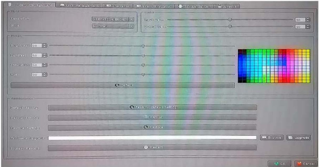
Resolution: Change monitor current display resolution and then confirm change result; the system will recover old resolution after 15 seconds.
Style: You may change the interface to Simple / Normal / Professional / Advance.
Image: Adjust monitor Brightness, Contrast, Saturation, Sharpness, and Hue value.

Only available on D-sub interface.
Maintenance
Default Setting: Reset all settings to factory default value.
Backup Setting: Export backup setting file to removable storage device.
Restore Setting: Restore a backup setting file from removable storage device.
Firmware Upgrade: Select a firmware file from removable storage device and then click "Firmware Upgrade" button to begin update firmware job.
System Restart: Restart CoreNVR system.
Audio: Adjust audio input or output gain value for better audio quality.
6.2. Disk Management
The NVR supports up to two 4TB HDDs installed in the system. You may also manage all USB storage devices on this page.
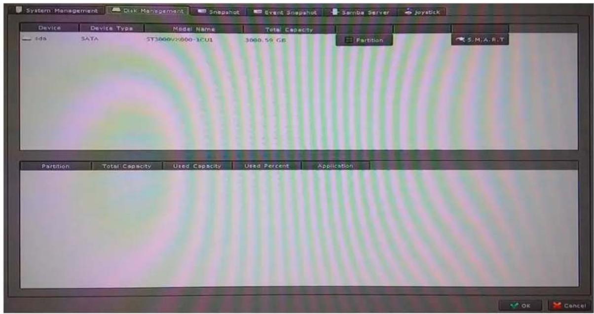
Device List: Display all devices detected on NVR and their information.
Partition Button: Select a storage device and click "Partition" button. System will remove all data and partitions on selected device, and create a new partition.
Mount / Un-mount Button: Mount or un-mount USB stick.
S.M.A.R.T Button: Display the Hard Disk S.M.A.R.T status.
Partition List: Display all partitions of selected device and their information. Clicking "Format" button will format selected partition to "ext4" format; all data will be lost.
6.3. Snapshot
You may save your video snapshot and save them to the HDD or any removable USB device.
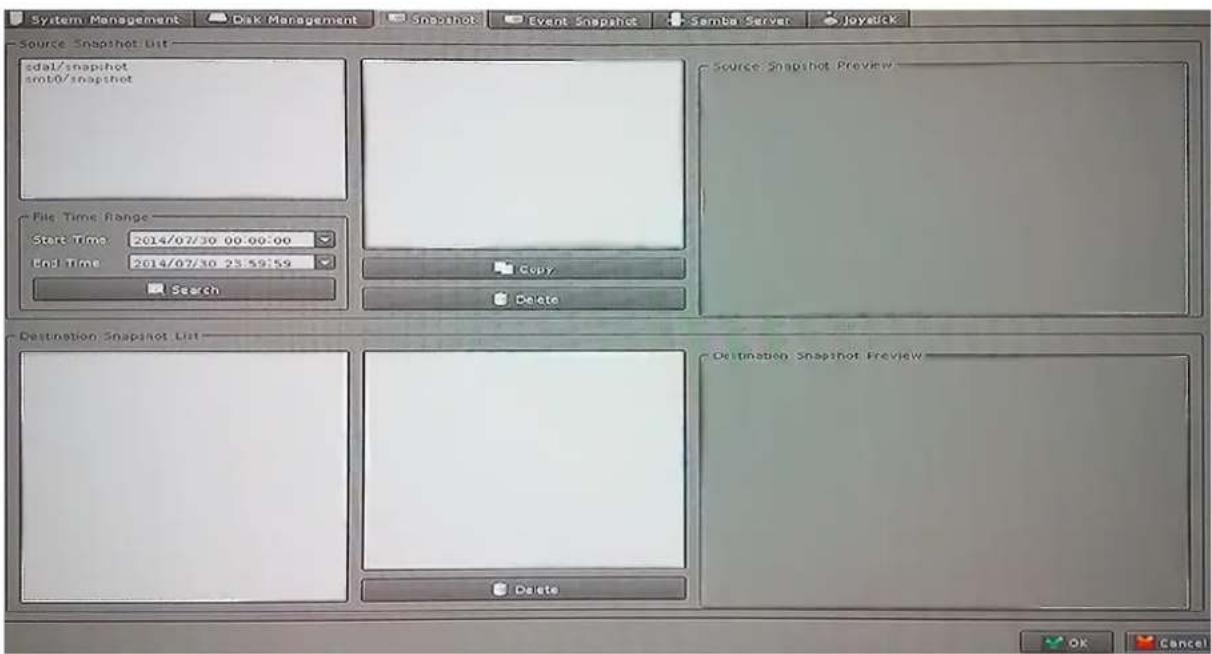
Source Snapshot List:
Search snapshot image:
- Select a hard disk path
- Select a time period
- Click "search" button
- The search result will display in the list box.
- Select a snapshot file name; the snapshot image will display on the right of window
Copy: Clicking "Copy" button will copy selected snapshot file to removable device.
Delete: Clicking "Delete" button will delete selected snapshot file.
Destination Snapshot List:
- Select a removable device path
- System will show snapshot file's name of selected folder
- Select a snapshot file name; the snapshot image will display on the right of window
Delete: Clicking "Delete" button will delete selected snapshot file.
6.4. Event Snapshot
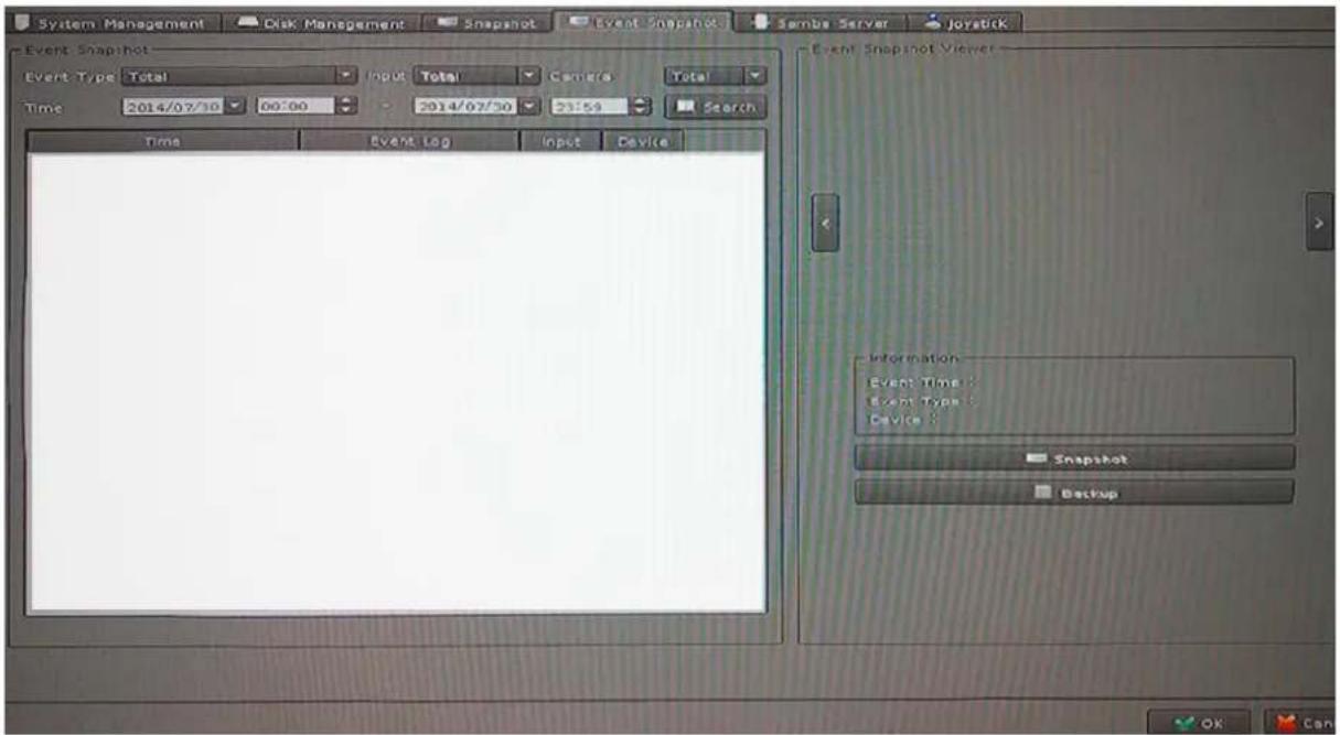
Event Snapshot:
Event Type: Select trigger snapshot event type.
Input: Select DI input port number.
Time: Select search time period.
Search: To search event snapshot based on the condition you set above.
Result Table:
Time: Event Time.
Event Type: Triggered Event Type.
Input: Event DI port number, if not DI event will fill -1.
Device: Event triggered device ID.
Snapshot Viewer: Select an event from search result table and click the "Play" button. The snapshot video will display on the right of window.
Next Frame: Click “>” button for next frame.
Pre Frame: Click "<" button for pre-frame.
Information: Display snapshot video information.
Snapshot Button: Click "Snapshot" button and save snapshots to removable device.
Backup Button: Clicking "Backup" button will back up this event video to removable device.
6.5. Samba Server
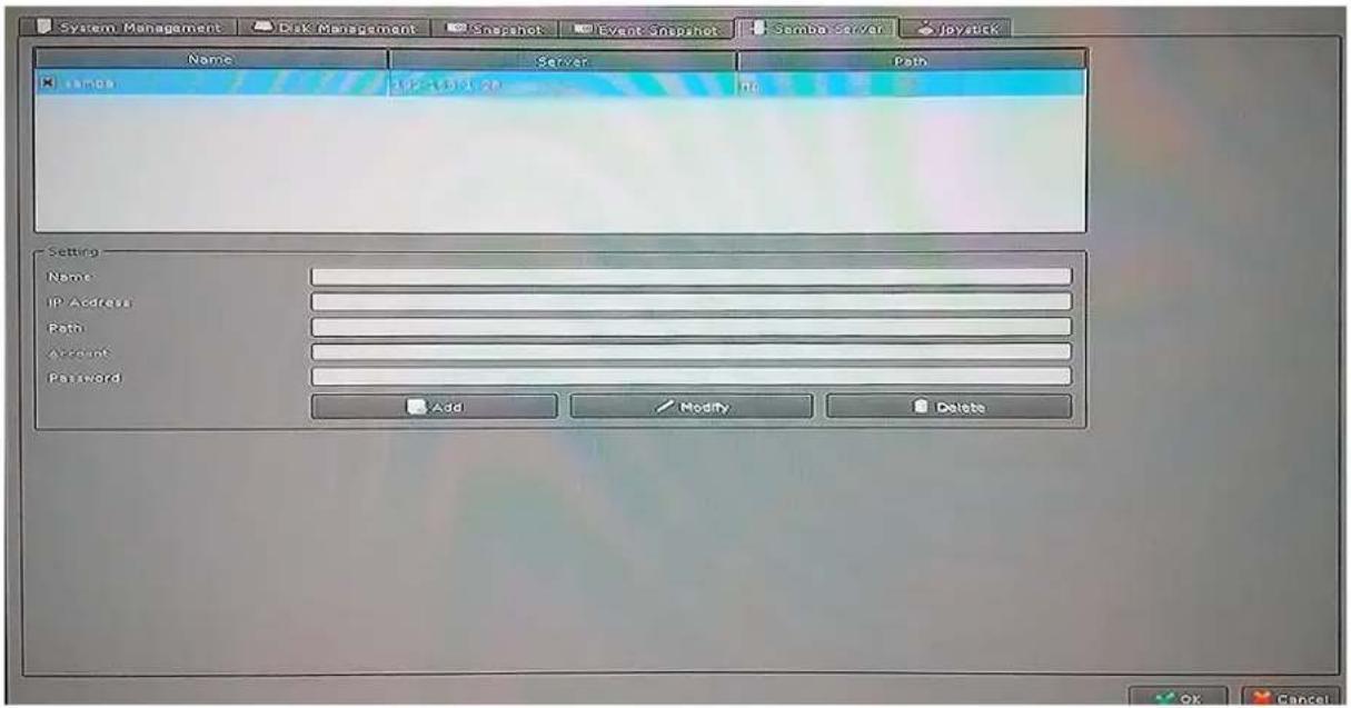
Name: Key-in Samba server name to identify server.
IP Address: Samba server IP address.
Path: Key-in Samba server recording path.
Account: Login Samba server account.
Password: Login Samba server password.
Add Button: Key-in all Samba server information and then Click "Add" button to add to samba server list.
Modify Button: Select a Samba server from list and then modify server's information. when the modify job is done, click the "Update" button to save.
Delete Button: Select a Samba server in the list and then click "Delete" Button to remove it from list.
Chapter 7. Event Setting
You may define each event alarm on a different day and actions for each camera or NVR system. Please refer to the operating instructions below.
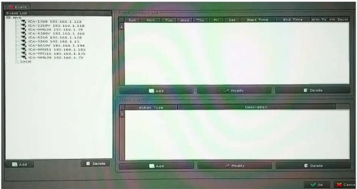
7.1 Add a New Event
- Select a camera or local from tree list
- Click "Add" button in the below device list.
- Select an event from table.
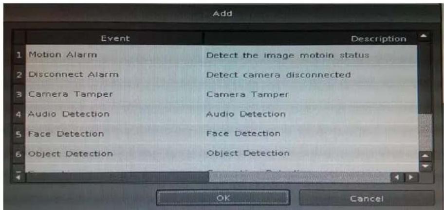
Motion Alarm: Camera's motion detection. Please set the camera motion first.
Disconnect Alarm: Lost camera connection.
Digital Input_0 \~ Digital Input_4: Detected input.
Schedule Trigger: Triggered by schedule setting.
HDD Error Alarm: Failed recording or HDD error will send event alarm.
- Click "Add" button in the below Event Schedule List.
- Selecting event will detect weekdays and the time of each day.
- Set up alarm detail parameter.
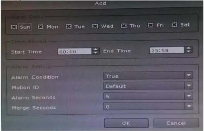
Weekdays: Select weekdays for event notification.
Time Period: Select time period for event notification.
Alarm Setting
Alarm Condition:
For Motion event, true means alarm triggered by motion; false means alarm triggered by no motion.
For DI event, true means alarm triggered by DI in open status; false means alarm triggered by DI in close status.
For Schedule trigger, true means alarm is triggered during scheduled period; false means alarm triggered when not in scheduled period.
Alarm seconds: Define the alarm time period when the event is triggered.
Merge seconds: Set for merging the same two alarms between setting seconds.
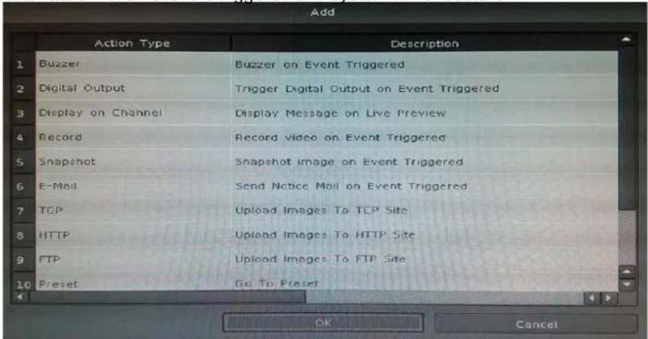
- Click "Add" button in the below Action list.
- Select an action when event is triggered and system will execute it.
7.2 Modify Existing Event Schedule or Output Action
Modify Event Schedule:
- Select an event from event list.
- Select a schedule from event schedule list.
-
Click "Modify" button.
-
Modify setting values from schedule setting dialog.
- Click "OK" button when the modification is done.
Modify Output Action:
- Select an event from event list.
- Select a schedule from event schedule list.
- Select an action from "Action List".
- Click "Modify" button.
- Modify setting values from each Action setting dialog.
- Click "OK" button to close dialog.
7.3 Delete Existing Event Schedule or Output Action
Delete Event:
- Select an Event from "Event List".
- Click "Delete" button in the below "Event List".
Delete Event Schedule:
- Select an event from "Event List".
- Select an event schedule from "Event Schedule List".
- Click "Delete" button in the below "Event Schedule List".
Delete Action:
- Select an event from "Event List".
- Select an event schedule from "Event Schedule List".
- Select an Action from "Action List".
- Click "Delete" button in the below "Action List".
7.4 Event Action Type
Buzzer: Buzzer works after event is triggered.
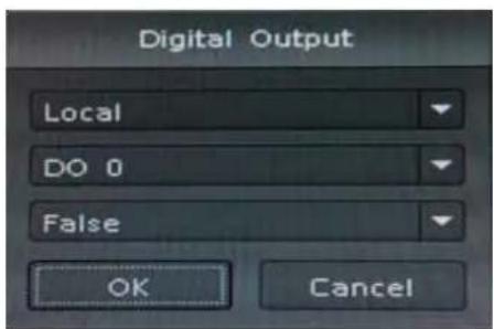
Digital Output: Select a device to change DO status after event is triggered.
Set output to "True", DO will change to "Close" status when alarm is triggered.
Set output to "False", DO will change to "Open" status when alarm is triggered.
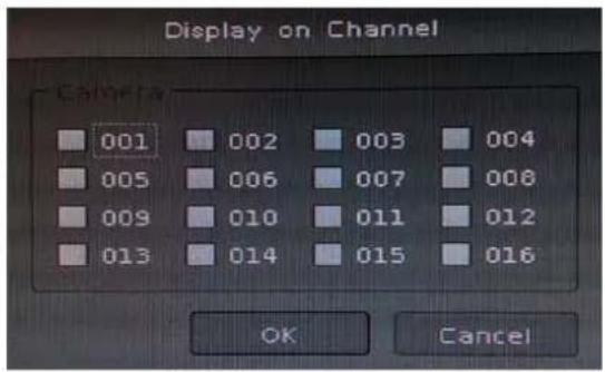
Display on Channel: When event is triggered, system will display OSD string on selected channels.
Record: When event is triggered, system will force selected channels record.

- System must switch to "Schedule Monitoring" when event is triggered.
- The selected channels must set to "Recording schedule" when event is triggered.
Snapshot:
System will snapshot images with selected channels, and save snapshots to event snapshot folder automatically. You could search them on "Event Snapshot" page under "System Management".
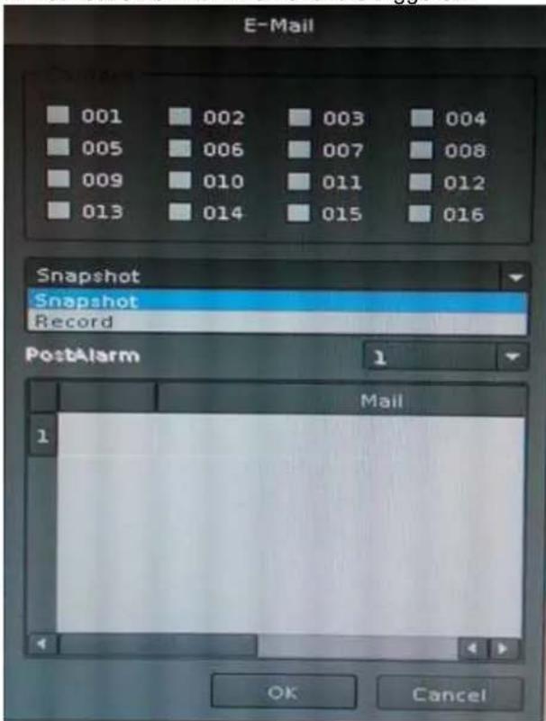
E-mail:
- Select channels for snapshot or record a file when event is triggered.
- Select Snapshot or Record a period video file.
- Set up Pre-Alarm seconds and Post-Alarm seconds for record file.
- Select users to send notification e-mail when event is triggered.
TCP: Send notification of TCP sockets to TCP server when event is triggered.
HTTP: Send notification to HTTP server when event is triggered.
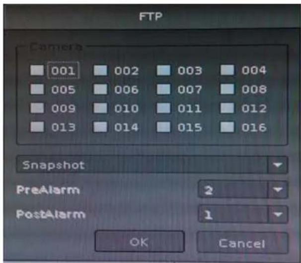
FTP:
- Select channels for snapshot or record a file when event is triggered.
- Select Snapshot or record a video file in a specified time.
- Set up Pre-Alarm seconds and Post-Alarm seconds for recording.
Chapter 8. Log Viewer
8.1 System Log
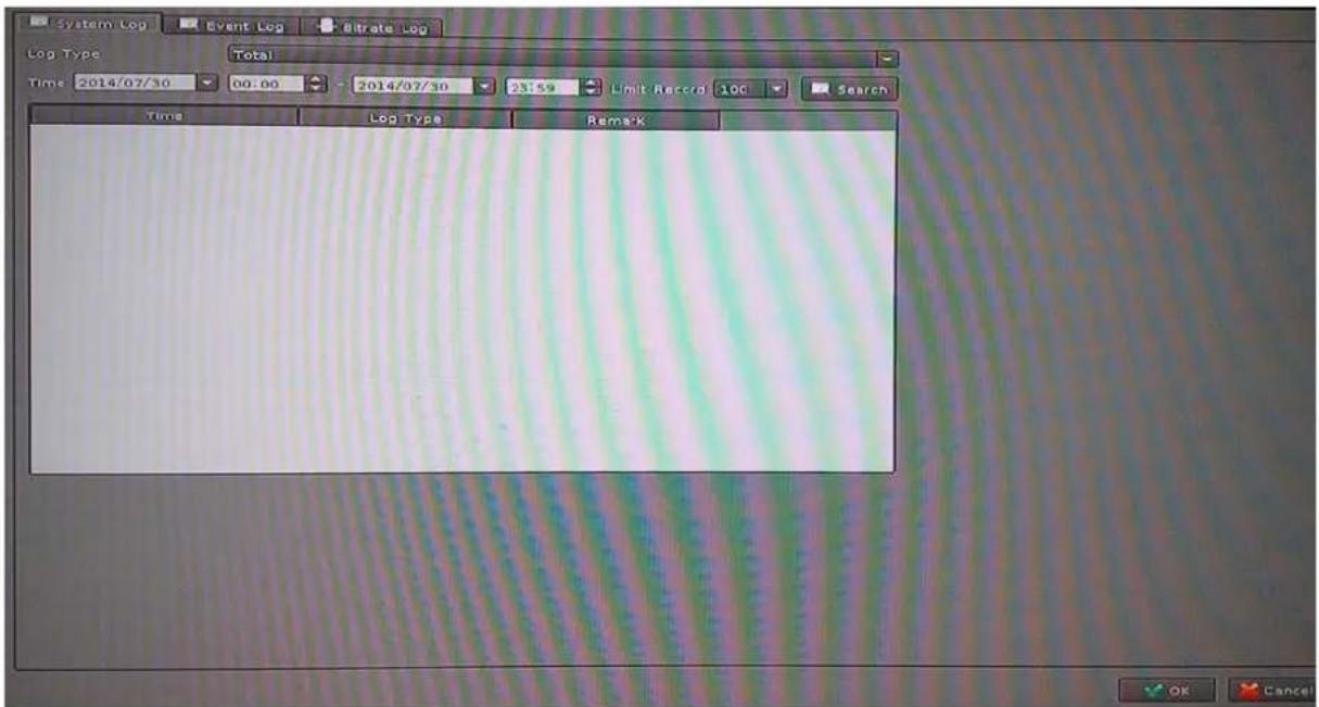
Log Type: Select a log type to filter data.
Time: Set up search logs in time period.
Limit Record: Set up maximum number records of search result.
Search: Click "Search" button to start search; the search result will display in the table below.
8.2 Event Log
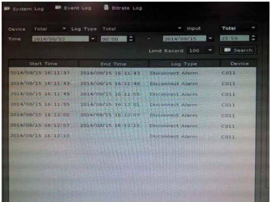
Device: Select a Device for search filter.
Log Type: Select a log type to filter data.
Input: Set up DI input port search filter; only works on search DI event.
Time: Set up search logs in time periods.
Limit Record: Set up maximum number records of search result.
Search: Click "Search" button to start search; the search result will display in the table below.
Preview Event Images: Select an event log from log table. Event image will display in the window. You could click the play control buttons to preview event images.
Change Display Channel: Select another camera ID from combo box. System will display selected channel image in event time.
Snapshot: Insert USB dongle into the NVR first and click the Snapshot button to save it.
8.3 Bitrate Log
You may search bitrate for selected time period; it will show a different color of bitrate data as seen below.
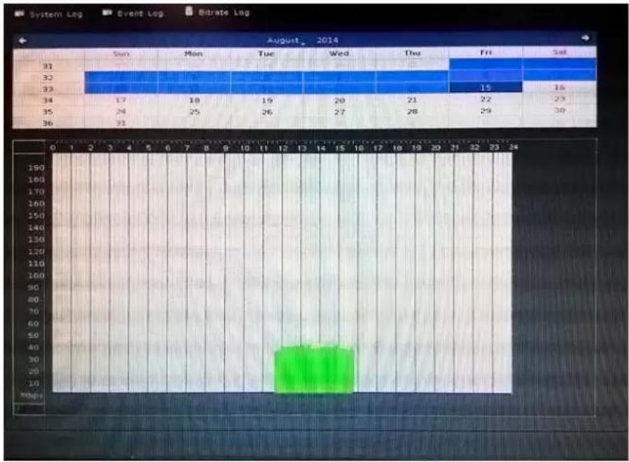
Select a date: Click on the calendar with blue background days.
Bit-rate table: System will display the bit-rate log in the table.
Blue: Bit-rate is very low.
Green: Bit-rate is fine.
Yellow: Bit-rate is a bit high.
Orange: Bit-rate is very high.
Red: Bit-rate is over limit.
Chapter 9. Playback
You may search and play back the recorded video files with selectable time period and is also able to convert the video into AVI or back up the video files.
9.1 Search Recorded Video Files
Click button to approach search dialog.
Normal Search:
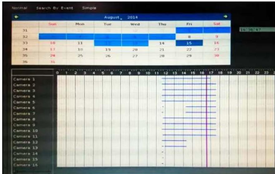
- Select playback date: If there is record history data, system will set calendar's day to blue to identify which days has recorded files.
- Begin search: Click "Search" button to start search record file in selected date and system will draw search result in the grid.
- Select playback camera and time period: Select cameras from list, and drag on search result or edit start / end time from date-time picker control to define playback period.
- Begin playback: Confirm playback camera and period and then click "OK" button to begin playback.
Search by Event:
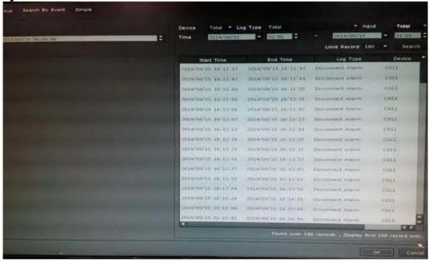
Input search filter first by clicking the "Search" button; the search result will display on the list as shown above. Select a log that you need to play back. System will fill the event period automatically, and select which cameras you need to play back together. Click the "OK" button when the search is done.
Simple Search:
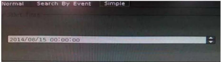
Select playback period from date controls directly and select which cameras will play back. Click the "OK" button when the search is done.
9.2 Playback Control Buttons
Parameter
Description

Play video forward

Pause playing video

Stop playing video

Play video backward

Seek to previous frame when in pause mode

Seek to next frame when in pause mode
9.3 Convert into AVI File

- Click button to open search dialog.
- Select convert camera(s) and time period for converting
- Select converted files destination folder and then click "OK".
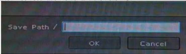
9.4 Backup Video File

- Click button to open backup dialog.
- Select backup camera(s) and time period for backup.
- Select backup files destination folder and then click "OK".
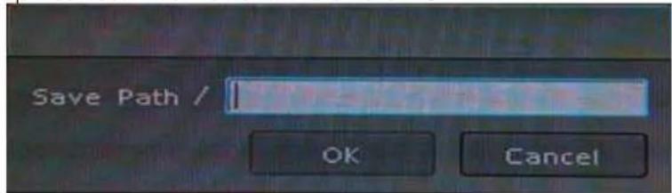
Chapter 10. Web Remote Management
The NVR is able to be viewed from Internet Explorer when the network is available. You can have live view or playback, and most of the functions are the same as the NVR system.
10.1 Connection to NVR
For the first-time connection, you need to install the ActiveX control if it appears on your web page as shown below.
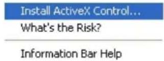
After installing the ActiveX component, login the system on pop-up window.
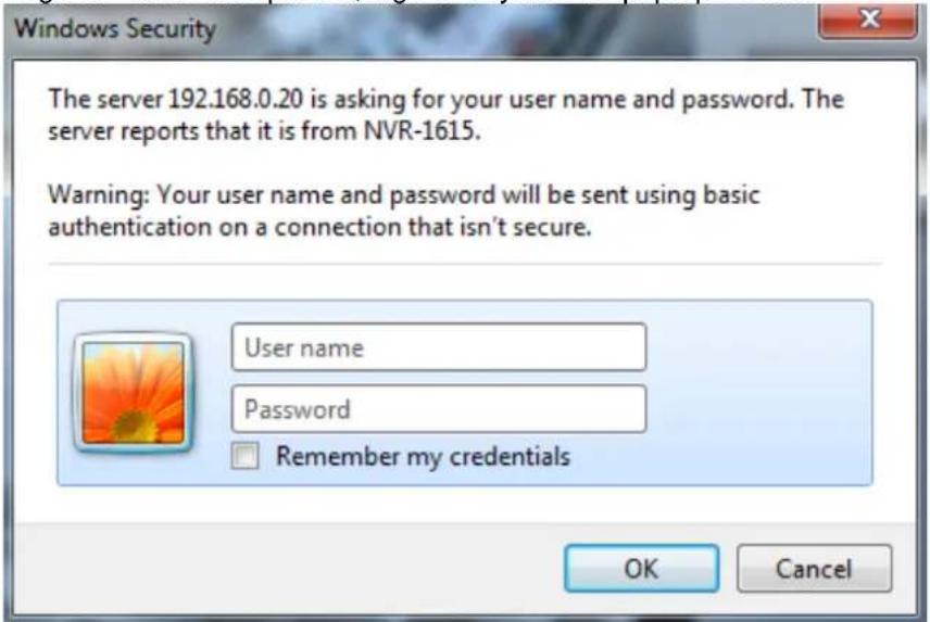
Please login your username and password and then you will see the "Select View Channel" window as shown below.
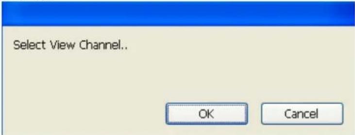
You may select channel(s) you would like to view on your computer. Please also check the "Low Bitrate" to reduce the bandwidth consumption on IE.
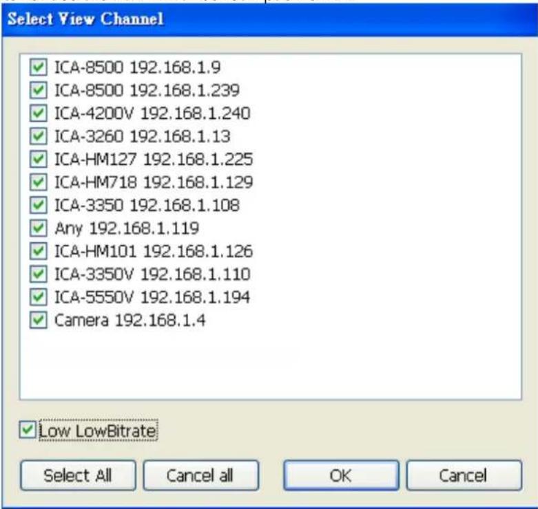
Click on "OK" to see the live view.
10.2 Live View on Internet Explorer
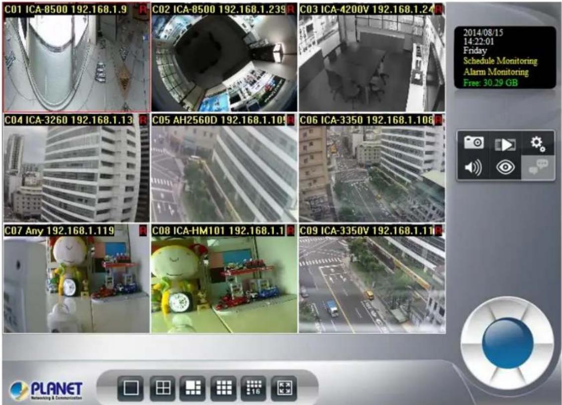
The picture below is the live view on IE, which is exactly the same as NVR system.
10.3 System Information
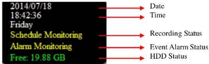
10.4 Screen Division

Switch to 1 division

Switch to 4 division

Switch to 9 division

Switch to Full screen and right-click mouse to cancel Full Screen.
Logout / firmware version display
10.5 Sub-screen Functions
| Show Live CameraRemove Camera displayDigital ZoomSnapshotFullscreenRestore division default | Right-click mouse to select an option from the popup menu. |
| Popup Menu | |
| Show Live Camera | You may select any connected camera to display on selected channel |
| Remove Camera Display | You may remove the camera from selected channel |
| Digital Zoom | You must enable this function to zoom the selected camera on the Web |
| Snapshot | Take a snapshot of selected channel |
| Full Screen | Make full screen of selected channel |
| Restore Division Default | Restore to default division when you finish full screen view |
 | Click it for System setting / System Management / Event Setting/ Log Viewer |
 | Click it to go to “Playback” page |
| Playback | |
 | Click it to take a snapshot to the HDD; you can manage snapshots at “snapshot” page of system management |
| Snapshot | |
 | Click it to switch between normal and mute |
| Audio Volume Control | |
 | Click it to enable or disable schedule monitoring, the recording will be stopped if it is disabled |
| Schedule Monitoring | |
 | Click it to start or stop two-way audio of selected channel |
| Two-way Audio | |
 | Move PTZ camera direction by clicking direction buttons |
| PTZ Control | |
 | Click it to make camera return to home position |
| PTZ Control_Home | |
 | Move the thumb to control speed |
 Tour Tour | Select a tour setting from combo box and click “go” button to start tour, click “Stop” button to stop tour |
 Preset Preset | Select a preset position from combo box and camera will move to preset position after clicking |
 IRIS IRIS | Adjust camera's IRIS setting, or set it to auto |
 Focus Focus | Adjust camera's focus setting, or set it to auto |
 Zoom Zoom | Zoom-in or zoom-out focus |
 PAN PAN | Start camera auto pan or stop |
10.6 Playback on Internet Explorer





Click it to go to "Playback" page
Play video forward
Pause playing video
Stop playing video
Play video backward
Seek to previous frame when in pause mode
Seek to next frame when in pause mode
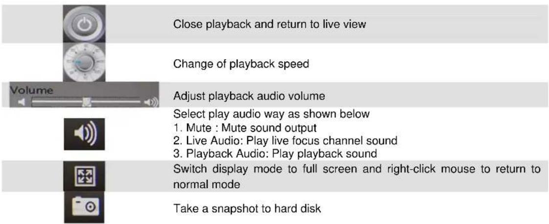
Close playback and return to live view
Change of playback speed
Adjust playback audio volume
Convert into AVI; please see chapter 9.3 for information
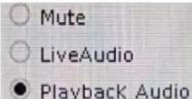
Select play audio way as shown below
-
Mute : Mute sound output
-
Live Audio: Play live focus channel sound
-
Playback Audio: Play playback sound.

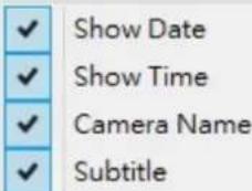
To select which information you would like to show as seen below
Search recorded video files; please see chapter 9.1 for information
Take a snapshot to hard disk
Back up video files; please see chapter 9.4 for information
- 9-Channel
- Network Video Recorder
- Copyright
- Federal Communication Commission Interference Statement
- FCC Caution
- Federal Communication Commission (FCC) Radiation Exposure Statement
- Safety
- CE Mark Warning
- WEEE Regulation
- Energy Saving Note of the Device
- Revision
- Table of Contents
- Chapter 1. Product Description....6
- Chapter 2. Hardware Installation....12
- Chapter 3. Connecting to the NVR .....15
- Chapter 4. System....20
- Chapter 5. System Setting....23
- Chapter 6. System Management ....36
- Chapter 1. Product Description
- Product Features
- Hardware
- Video / Audio
- Video Recording / Backup
- Network Service
- Easy Installation & Management
- System Requirements
- Make sure your display DPI setting is set to default at 96DPI
- Packet Contents
- Specifications
- Physical Specifications
- Chapter 2. Hardware Installation
- Accessories Check
- Installation
- Chapter 3. Connecting to the NVR
- Use Device Search Utility
- Access NVR with its default IP address
- Chapter 4. System
- Main Console
- System Information
- Screen Division
- Sub-screen Functions
- Chapter 5. System Setting
- Camera Setup
- Audio Setting
- Template Setting
- Camera List
- Switch Camera sequential
- Quick Setup
- Camera Setup
- Parameter Setting
- Add Camera:
- Delete Camera:
- Update Camera setting:
- Search Camera
- Schedule Setting
- The step to configure recording schedule
- Network Setting
- Network
- PPPoE
- UPnP
- UPnP Transversal
- Server
- DDNS
- System Setting
- Device Information
- Date & Time Info
- Adjust:
- Manual:
- Synchronize with NTP (default):
- User Setting
- Motion Detection Setting
- Address Book Setting
- Notification Setting
- Chapter 6. System Management
- System Management
- Maintenance
- Disk Management
- Snapshot
- Source Snapshot List:
- Search snapshot image:
- Destination Snapshot List:
- Event Snapshot
- Event Snapshot:
- Result Table:
- Samba Server
- Chapter 7. Event Setting
- Add a New Event
- Alarm Setting
- Alarm Condition:
- Modify Existing Event Schedule or Output Action
- Modify Event Schedule:
- Modify Output Action:
- Delete Existing Event Schedule or Output Action
- Delete Event:
- Delete Event Schedule:
- Delete Action:
- Event Action Type
- Snapshot:
- E-mail:
- FTP:
- Chapter 8. Log Viewer
- System Log
- Event Log
- Bitrate Log
- Chapter 9. Playback
- Search Recorded Video Files
- Search by Event:
- Simple Search:
- Playback Control Buttons
- Convert into AVI File
- Backup Video File
- Chapter 10. Web Remote Management
- Connection to NVR
- Live View on Internet Explorer
- System Information
- Screen Division
- Sub-screen Functions
- Playback on Internet Explorer
Brand : Planet
Model : NVR-915
Category : Video recorder