
ELPMB24 - Projector mount EPSON - Free user manual and instructions
Find the device manual for free ELPMB24 EPSON in PDF.
| Product Type | Wall Mount Projector Support |
| Brand | EPSON |
| Model | ELPMB24 |
| Mounting Kit Weight | Approximately 10 kg (22 lb) |
| Total Supported Weight (projector + kit) | Up to 14 kg (31 lb) |
| Arm Length (max) | 1240 mm (48.8 inches) |
| Vertical Sliding Adjustment | 0 to 140 mm (5.5 inches) |
| Vertical Tilt Adjustment | 0 to ±7° |
| Horizontal Rotation Adjustment | 0 to ±5° |
| Horizontal Roll Adjustment | 0 to ±5° |
| Horizontal Sliding Adjustment | 0 to ±45 mm (1.8 inches) |
| Compatible Projectors | EPSON EB-410W / PowerLite 410W (short throw) |
| Wall Mount Type | Wall plate with M8 mounting lugs or 8x80 mm lag screws (not included) |
| Recommended Wall Material | Reinforced concrete or metal construction |
| Minimum Number of Installers | 2 qualified technicians |
| Package Contents | Projector plate, wall plate, covers, M4 and M8 bolts, Allen keys, installation manual |
| Maintenance | Clean with a dry cloth; regularly check that the screws are tight |
| Safety | Do not modify the kit; do not hang heavy objects; installation only by a professional |
| Operating Temperature | Respect the projector's temperature range (not specified in the manual) |
| Warranty | Not mentioned in the manual |
Frequently Asked Questions - ELPMB24 EPSON
User questions about ELPMB24 EPSON
0 question about this device. Answer the ones you know or ask your own.
Ask a new question about this device
Download the instructions for your Projector mount in PDF format for free! Find your manual ELPMB24 - EPSON and take your electronic device back in hand. On this page are published all the documents necessary for the use of your device. ELPMB24 by EPSON.
USER MANUAL ELPMB24 EPSON
Short Throw Projector Wall Mount Installation Manual
Manuel d'installation du kit de montage mural du projecteur à courte distance de projection Installationsanleitung für Projektorwandhalterung für kurze Projektionsabstände Manuale di installatione della staffa da parete per proiettre a foscaleorta Manual de instalacion del soporte de pared para projectores con enfoque corto
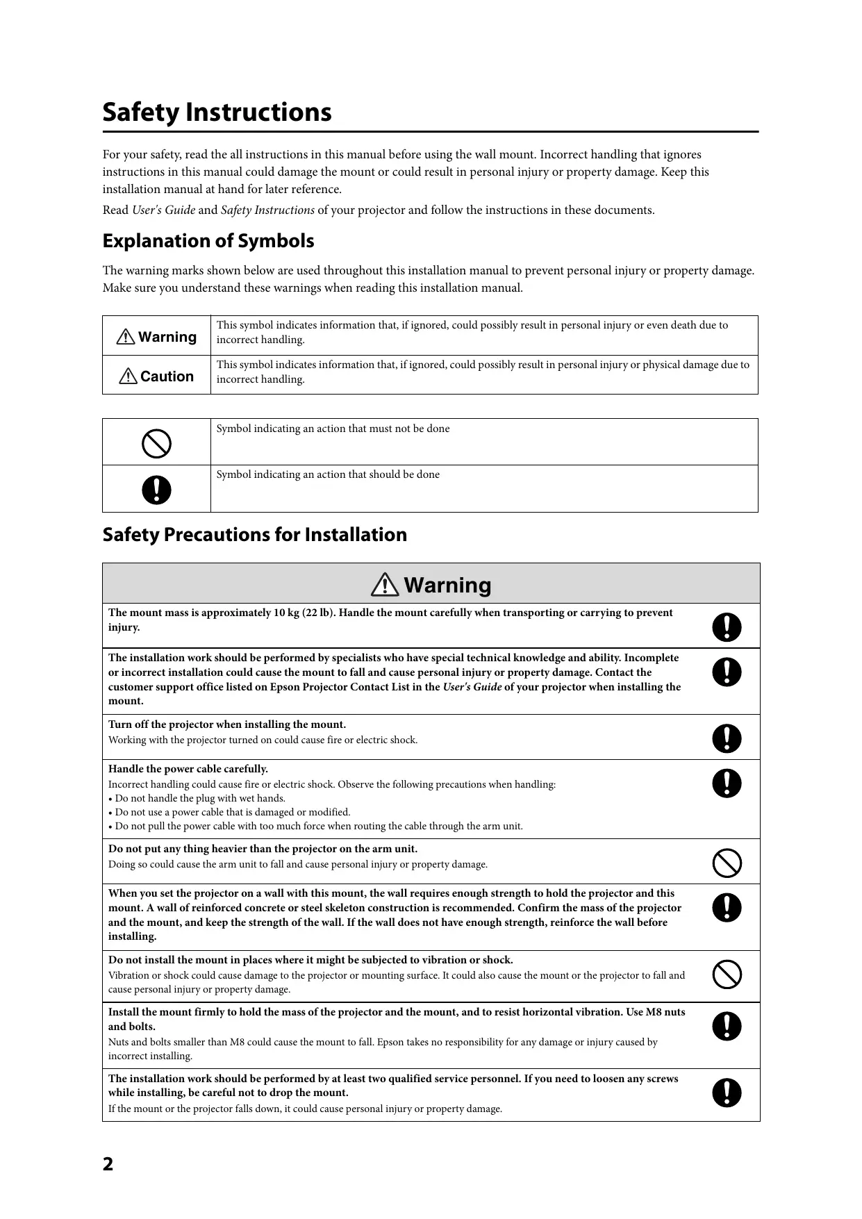
For your safety, read the all instructions in this manual before using the wall mount. Incorrect handling that ignores instructions in this manual could damage the mount or could result in personal injury or property damage. Keep this installation manual at hand for later reference.
Read User's Guide and Safety Instructions of your projector and follow the instructions in these documents.
Explanation of Symbols
The warning marks shown below are used throughout this installation manual to prevent personal injury or property damage. Make sure you understand these warnings when reading this installation manual.
| Warning | This symbol indicates information that, if ignored, could possibly result in personal injury or even death due to incorrect handling. |
| Caution | This symbol indicates information that, if ignored, could possibly result in personal injury or physical damage due to incorrect handling. |
| ⊗ | Symbol indicating an action that must not be done |
| ! | Symbol indicating an action that should be done |
Safety Precautions for Installation
| Warning | |
| The mount mass is approximately 10 kg (22 lb). Handle the mount carefully when transporting or carrying to prevent injury. | ! |
| The installation work should be performed by specialists who have special technical knowledge and ability. Incomplete or incorrect installation could cause the mount to fall and cause personal injury or property damage. Contact the customer support office listed on Epson Projector Contact List in the User's Guide of your projector when installing the mount. | ! |
| Turn off the projector when installing the mount. Working with the projector turned on could cause fire or electric shock. | ! |
| Handle the power cable carefully. Incorrect handling could cause fire or electric shock. Observe the following precautions when handling: Do not handle the plug with wet hands. Do not use a power cable that is damaged or modified. Do not pull the power cable with too much force when routing the cable through the arm unit. | ! |
| Do not put any thing heavier than the projector on the arm unit. Doing so could cause the arm unit to fall and cause personal injury or property damage. | ! |
| When you set the projector on a wall with this mount, the wall requires enough strength to hold the projector and this mount. A wall of reinforced concrete or steel skeleton construction is recommended. Confirm the mass of the projector and the mount, and keep the strength of the wall. If the wall does not have enough strength, reinforce the wall before installing. | ! |
| Do not install the mount in places where it might be subjected to vibration or shock. Vibration or shock could cause damage to the projector or mounting surface. It could also cause the mount or the projector to fall and cause personal injury or property damage. | ! |
| Install the mount firmly to hold the mass of the projector and the mount, and to resist horizontal vibration. Use M8 nuts and bolts. Nuts and bolts smaller than M8 could cause the mount to fall. Epson takes no responsibility for any damage or injury caused by incorrect installing. | ! |
| The installation work should be performed by at least two qualified service personnel. If you need to loosen any screws while installing, be careful not to drop the mount. If the mount or the projector falls down, it could cause personal injury or property damage. | ! |
| Do not use the mount when damaged. Doing so could cause the arm unit to fall and cause personal injury or property damage. | ○ |
| Never modify the mount. | ○ |
| Do not hang onto the mount. Or do not hang a heavy object on the mount. It is dangerous if the mount falls down. If the projector or the arm unit falls down, it could cause personal injury or property damage. | ○ |
| Stop using this mount and contact the customer support office listed on Epson Projector Contact List in the User's Guide of your projector when the following trouble occurs. • The mount is dropped and/or damaged during installation. • The arm is about to fall. | ○ |
| If you use adhesives to prevent the screws from loosening or things such as lubricants or oils on the mount, the case may crack and this could cause the projector to fall. It could cause personal injury or property damage. Do not use adhesives, lubricants or oils to install or adjust the mount. | ○ |
| Tighten all screws firmly after adjustment. If the screws are not properly tightened, it could cause the projector to fall and cause personal injury or property damage. | ○ |
| Never loosen the bolts and nuts after installation. Confirm that the screws have not become loosened on a regular basis. If you find any loose, tighten the screws firmly. If the screws are not properly tightened, it could cause the projector to fall and cause personal injury or property damage. | ○ |
| Caution | |
| Do not use in places where the humidity is high. High humidity could cause fire or electric shock. | ◎ |
| Do not install at place where there is a lot of dust, or a place where it may come into contact with smoke or steam such as near cooking appliances or a humidifier. These could cause fire or electric shock. | ◎ |
| Do not change the angle of this mount or the projector with excess force. Too much force could damage the mount and could cause personal injury or property damage. | ◎ |
Before Usage
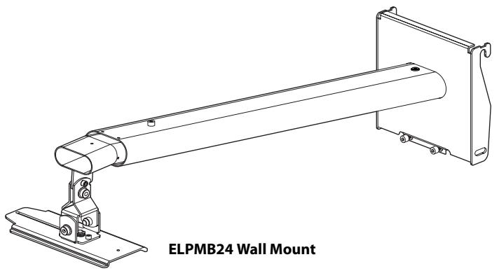
This product is for mounting an Epson Multimedia Projector on a wall.
Features
- This mount is for short throw projector EB-410W/PowerLite 410W.
Place to Install the Mount
- Perform the power engineering work in advance to the place where the mount is installed.
- Do not install the mount in places where it might be subjected to vibration or shock. It could cause damage to the projector or mounting surface. It could also cause this mount or the projector to fall and cause serious injury or even death.
- Install the projector at a place away from other electric devices such as fluorescent lights or air conditioning. Some kinds of fluorescent lights could interfere with the remote control of the projector.
It is recommended to keep connection cable length less than 20 meters to reduce the external noise. - Install the mount in place where there is less dust and humidity to prevent the lens or optical components from becoming dirty.
- Do not install the mount at a place where the operating temperature for your projector might be exceeded. This type of environment could damage the projector.
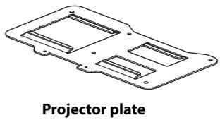
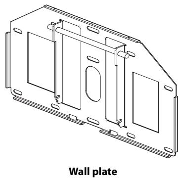
Package Contents

M4× 12 mm hexagon socket head cap bolt with washers (2 pcs.)
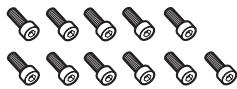
M4× 12 mm hexagon socket head cap bolt without washers (11 pcs.)
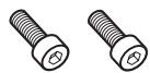
M8× 16 mm hexagon socket head cap bolt without washers (2 pcs.)
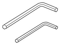
Hexagon wrench (M4, M8)
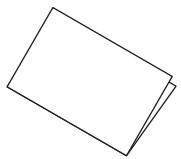
Installation manual (this manual)
- Use the bolts supplied with this mount to install it, as directed in this manual. Do not substitute these bolts with any other types. In addition, you need to use M8 × 50 ~mm anchors (at least 3 pcs.) and 8 × 80 ~mm lag bolts (at least 3 pcs.) that are available at the store to attach the wall plate to the wall.
- Gather the tools and parts you need before you begin installation.
| Mass | Approx. 10 kg (22 lb) |
| Arm length | Approx. 1240 mm (48.8 in.) (maximum) |
| Vertical slide adjustment range | 0 to 140 mm (5.5 in.) |
| Vertical tilt adjustment range | 0 to ± 7° |
| Horizontal rotation adjustment range | 0 to ± 5° |
| Horizontal roll adjustment range | 0 to ± 5° |
| Horizontal slide adjustment range | 0 to ± 45 mm (1.8 in.) |
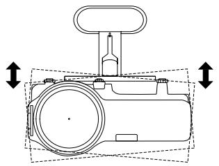
Vertical tilt adjustment
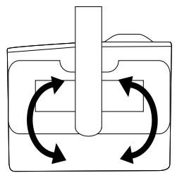
Horizontal rotation adjustment
Horizontal roll adjustment
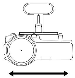
Horizontal slide adjustment
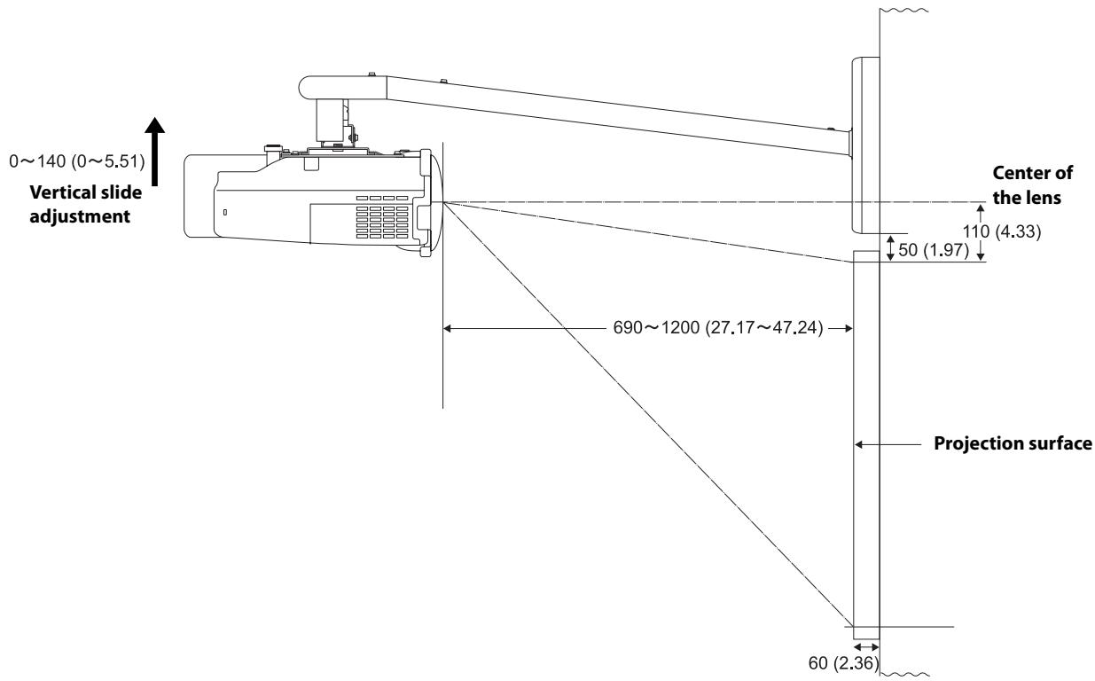
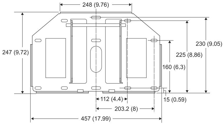
Units: mm (inches)
Refer to the table below and install the mount and projector to project images with appropriate size. The value is only as a guide. The recommended projection distance is 69 to 119cm (27 to 47 in.).
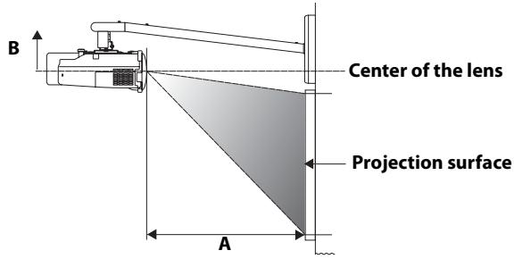
Units: cm (inches)
| Aspect ratio | Interactive whiteboard * | Screen size | Projection distance (A) Minimum (Wide) | Vertical slide adjustment (B) |
| 4:3 | 59" (min.) | 69 (27.17) | 0 | |
| Hitachi Cambridge Board 60 | 60" | 70 (27.56) | 0 | |
| Hitachi StarBoard FX-63 | 63" | 74 (29.13) | 0 | |
| Prometheus Activboard 64 | 64" | 75 (29.53) | 0 | |
| 70" | 82 (32.28) | 0 | ||
| SMART Board 680 | 77" | 91 (35.83) | 0 | |
| Hitachi Cambridge Board 77 | 77" | 91 (35.83) | 0 | |
| Hitachi StarBoard FX-77 | 77" | 91 (35.83) | 0 | |
| RM ClassBoard 77.5 | 77.5" | 91 (35.83) | 0 | |
| Prometheus Activboard 78 | 78" | 92 (36.22) | 0 | |
| PolyVision TS610 | 78" | 92 (36.22) | 0 | |
| 80" | 94 (37.01) | 0 | ||
| 85" | 100 (39.37) | 0 | ||
| 90" | 107 (42.13) | 0 | ||
| 95" | 113 (44.49) | 0 | ||
| 100" (max.) | 119 (46.85) | 0 | ||
| 16:10 | 67" (min.) | 69 (27.17) | 0 | |
| 70" | 72 (28.35) | 0 | ||
| 75" | 78 (30.71) | 0 | ||
| PolyVision TS610 | 78" | 81 (31.89) | 0 | |
| 80" | 83 (32.68) | 0 | ||
| 85" | 88 (34.65) | 0 | ||
| 90" | 94 (37.01) | 0 | ||
| 95" | 99 (38.98) | 0 | ||
| 100" | 105 (41.34) | 0 | ||
| 105" | 110 (43.31) | 0 | ||
| 110" | 115 (45.28) | 0 | ||
| 113" (max.) | 119 (46.85) | 0 | ||
| 16:9 | 65" (min.) | 69 (27.17) | 4 (1.57) | |
| 70" | 74 (29.13) | 5 (1.97) | ||
| Interwrite 1071 | 71" | 75 (29.53) | 5 (1.97) | |
| 75" | 80 (31.50) | 5 (1.97) | ||
| Interwrite 1070 | 77" | 82 (32.28) | 5 (1.97) | |
| 80" | 85 (33.46) | 6 (2.36) | ||
| Hitachi StarBoard FX-82Wide | 82" | 88 (34.65) | 6 (2.36) | |
| Interwrite 1085 | 85" | 91 (35.83) | 6 (2.36) | |
| 90" | 96 (37.80) | 6 (2.36) | ||
| SMART Board 690 | 94" | 101 (39.76) | 7 (2.76) | |
| Prometheus Activboard 95 | 95" | 102 (40.16) | 7 (2.76) | |
| 100" | 108 (42.52) | 7 (2.76) | ||
| PolyVision TS810 | 104" | 112 (44.09) | 7 (2.76) | |
| 105" | 113 (44.49) | 7 (2.76) | ||
| 110" (max.) | 119 (46.85) | 7 (2.76) |
| Aspect ratio | Interactive whiteboard * | Screen size | Projection distance (A) Maximum (Tele) | Vertical slide adjustment (B) |
| 4:3 | PolyVision TS410 | 44" | 69 (27.17) | 11 (4.33) |
| 74" | 119 (46.85) | 11 (4.33) | ||
| 16:10 | 50" | 69 (27.17) | 11 (4.33) | |
| 84" | 119 (46.85) | 11 (4.33) | ||
| 16:9 | 48" | 69 (27.17) | 14 (5.51) | |
| RM ClassBoard 60 | 60" | 87 (34.25) | 15 (5.91)** | |
| Interwrite 1060 | 60" | 87 (34.25) | 15 (5.91)** | |
| 82" | 119 (46.85) | 17 (6.69)** |
- Product names are the trademarks or registered trademarks of their respective owners.
** Allow at least 6 cm (2.4 in.) space between the top of the whiteboard and the bottom of the wall plate.
Make sure to follow the steps below to install the mount. If you ignore these steps, the mount could fall down and could cause personal injury or property damage.
The combined mass of this mount and the projector is approximately 14kg (31 lb) at maximum. Before starting the installation, carefully check the construction, material, and strength of the wall and use the most appropriate methods to install.
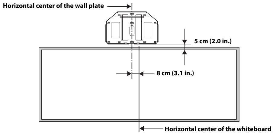
1. Installing the wall plate to the wall
Attach the wall plate to the wall using M8 × 50 ~mm anchor (more than 3 pcs.) or 8 × 80 ~mm lag bolt (more than 3 pcs.). Set the horizontal center of the wall plate 8 ~cm (3.1 in.) left from the horizontal center of the whiteboard. See the illustration below. Allow at least 6 ~cm (2.4 in.) space between the top of the whiteboard and the bottom of the wall plate. If the 16:9 of maximum distance (tele) screen size is used, refer to the table in the previous page. You can slide projector horizontally 4.5 ~cm (1.8 in.) after installing. See step 7 on page 10 for details.
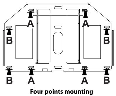
Insert the anchor or lag bolt into the place as shown below. Insert the anchors or lag bolts at least three points. If you insert at four points, use four point As or four point Bs as shown below.

Warning
- When you set the projector on the wall with this mount, the wall requires enough strength to hold the projector and this mount. A wall of reinforced concrete or steel skeleton construction is recommended. Confirm the mass of the projector and the mount, and keep the strength of the wall. If the wall does not have enough strength, reinforce the wall before installing.
Install the mount firmly to hold the mass of the projector and the mount, and to resist horizontal vibration. Use M8 nuts and bolts. Nuts and bolts smaller than M8 could cause the mount to fall.
Epson takes no responsibility for any damage or injury caused by incorrect installing.
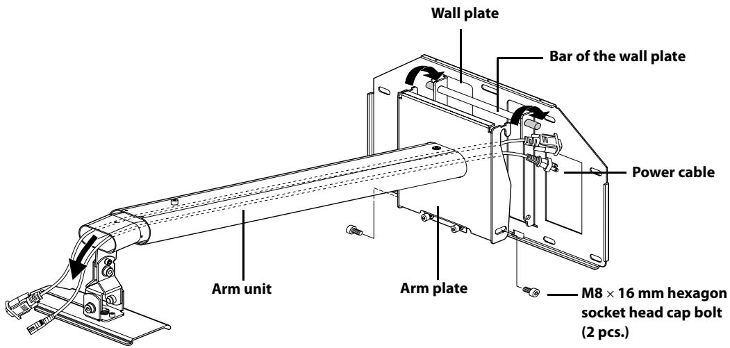
2. Attaching the arm unit to the wall plate
1) Route the cables through the arm unit as shown below.
2) Attach the hook on the arm plate to the bar on the wall plate.
Be careful not to pinch cables between the arm plate and the wall plate.
3) Secure the arm plate temporarily using two M8 × 16 ~mm hexagon socket head cap bolts.
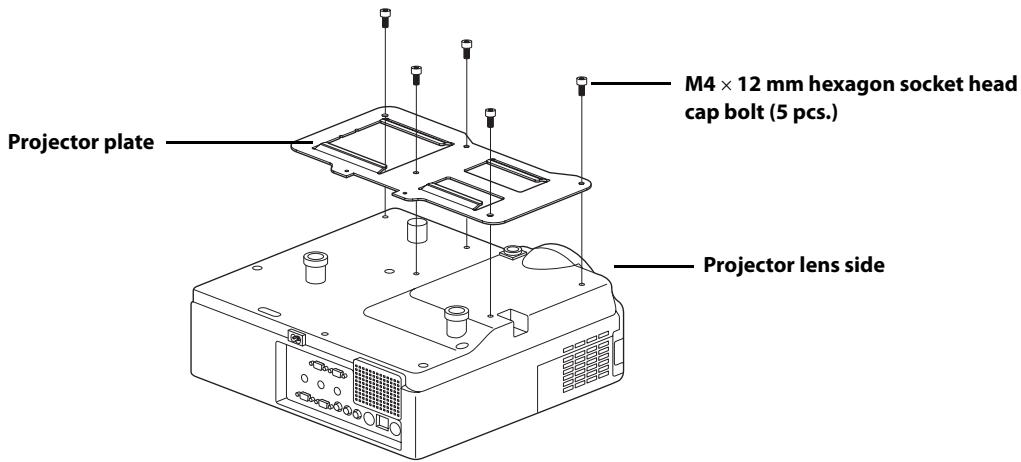
3. Attaching the projector plate to the projector
1) Place the projector upside down.
2) Attach the projector plate to the projector using the hexagon wrench (M4) and five M4× 12mm bolts.
Warning
If you use adhesives to prevent the screws from loosening or things such as lubricants or oils on the mount, the case may crack and this could cause the projector to fall. It could cause personal injury or property damage. Do not use adhesives, lubricants or oils to install or adjust the mount.

Tighten the screws firmly.
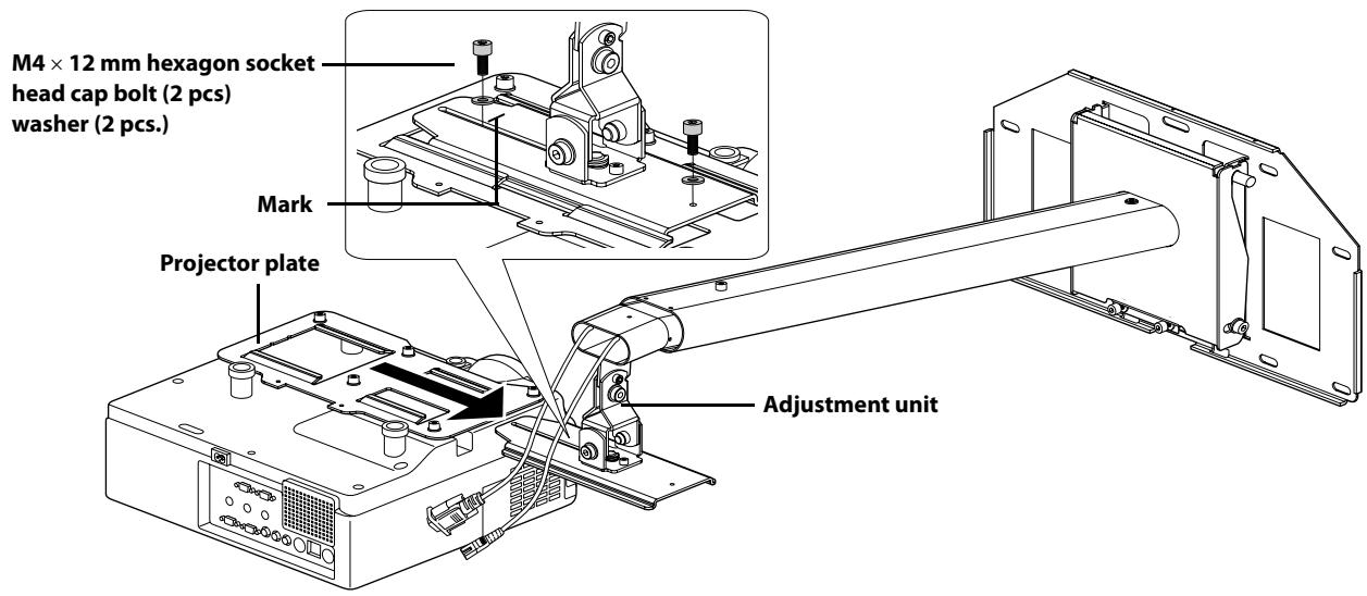
4. Installing the projector on the wall mount
1) Slide the projector plate onto the adjustment unit as shown below.
2) Secure the projector temporarily using two M4× 12mm bolts as shown below.
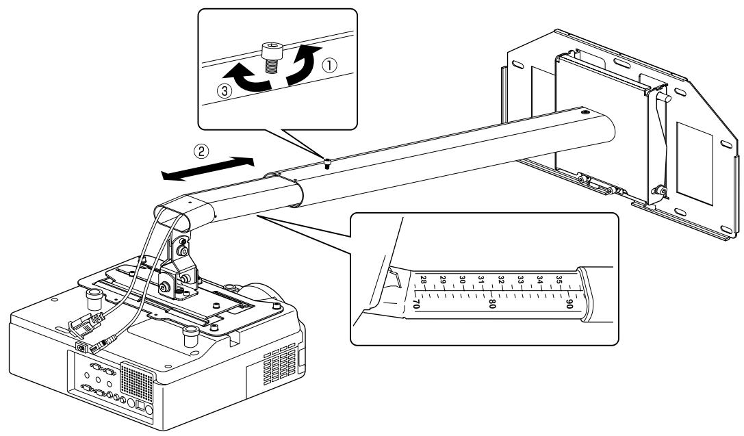
5. Adjusting the length of the arm
1) Loosen the screw on the arm. (①)
2) Adjust the length of the arm using the measure on the bottom to match the projection distance recommended in "Screen Size and Projection Distance" on page 6. (②)
3) Secure the arm position temporarily using the screw on top. (③)
6. Connecting the power cable and other cables to the projector
7. Turning on the projector and checking the screen
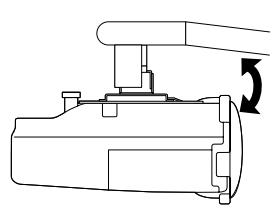
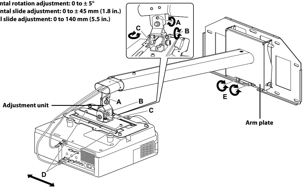
1) Loosen the screws on the adjustment unit (A, B, C, and D) as shown below to adjust the screen position.
2) If you project a 16:9 image at the minimum or maximum distance for your screen size, adjust the vertical slide (arm angle) using two screws (E) on the bottom of the arm plate. The arm goes up when tighten the screws and goes down when you loosen them.
Screw A: Vertical tilt adjustment: 0 to ± 7^
Screw B: Horizontal roll adjustment: 0 to ± 5^
Screw C: Horizontal rotation adjustment: 0 to ± 5^
Screw D: Horizontal slide adjustment: 0 to ±45 mm (1.8 in.)
Screw E: Vertical slide adjustment: 0 to 140mm (5.5 in.)
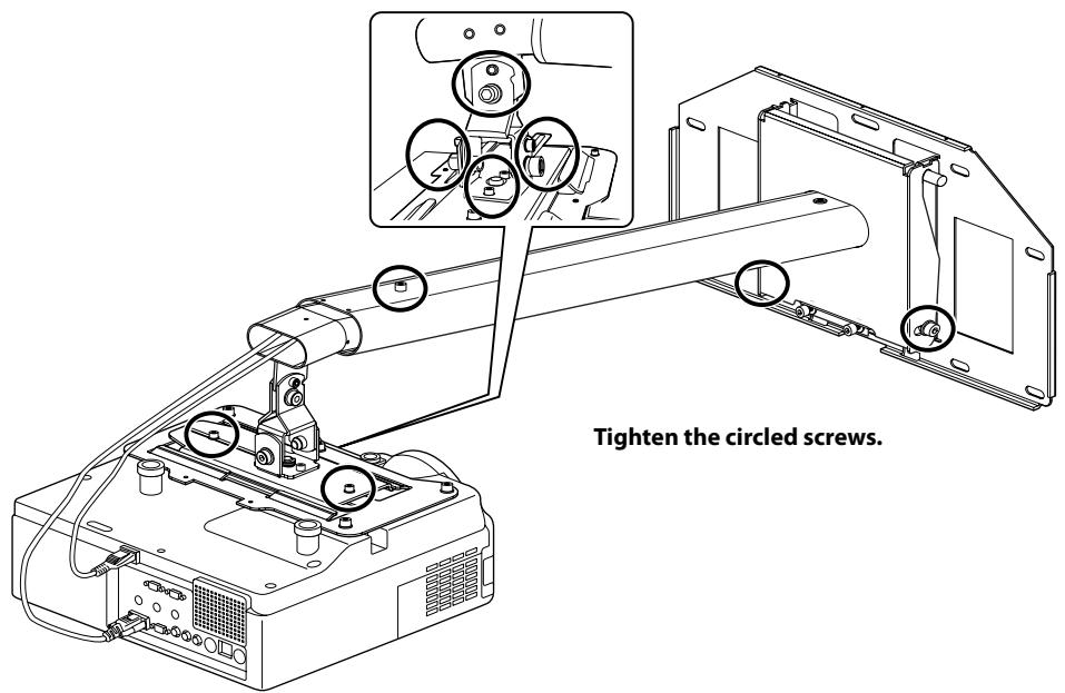
3) Firmly tighten the screws on the arm plate and adjustment unit using the hexagon wrench (M4 and M8).
Warning
Tighten all screws firmly. If the screws are not tightened firmly, it could cause the projector to fall and cause personal injury or property damage.
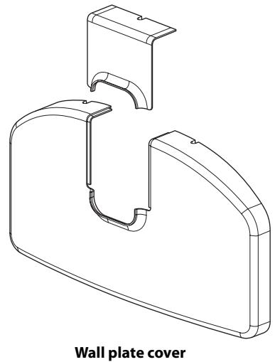
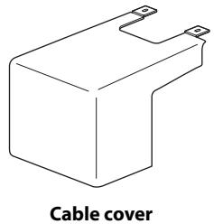
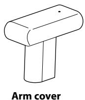
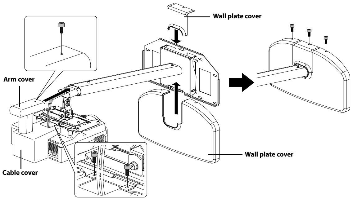
8. Attaching the protective covers
Attach the wall plate cover, cable cover, and arm cover using the hexagon wrench (M4) and six M4× 12mm bolts.
Only a specialist should remove or install the projector, including for maintenance and repairs. See User's Guide of your projector for instructions on maintenance and repairs.
Warning
- Never loosen the bolts and nuts after installation. Confirm that the screws have not become loosened on a regular basis. If you find any loose, tighten the screws firmly. If the screws are not tightened firmly, it could cause the projector to fall and cause personal injury or property damage.
Do not hang onto the mount. Or do not hang a heavy object on the mount. It is dangerous if the mount falls down. If the projector or the arm unit falls down, it could cause personal injury or property damage.