
TM-U220 - Receipt printer EPSON - Free user manual and instructions
Find the device manual for free TM-U220 EPSON in PDF.

| Product Type | Receipt Printer |
| Brand | EPSON |
| Model | TM-U220 |
| Available Types | A (with paper roll take-up and auto cutter), B (with auto cutter, no take-up), D (without auto cutter or take-up) |
| Print Technology | Impact Dot Matrix |
| Two-color Printing | Yes |
| Supported Paper Width | Type A: 76 mm; Types B and D: 76 / 69.5 / 57.5 mm |
| Interface | Serial or Parallel |
| Power Supply | Specific AC adapter (AC adapter C or PS-180 depending on model) |
| Consumables | EPSON ERC-38 Ribbon Cartridge |
| Dimensions (L × P × H) | Approx. 160 × 286 × 170 mm |
| Weight | Approx. 2.5 kg |
| Safety Standards | CE, FCC Class A, VCCI Class A, UL 60950, CSA 22.2 No. 60950 |
| Main Functions | Printing tickets, receipts, slips; auto cutter (types A and B); manual paper feed; status indicators (power, error, paper end) |
| Maintenance | Clean the print head regularly; replace used ribbon cartridge; use recommended paper and ribbon |
| Safety | Do not open the cover while printing; allow the print head to cool before any intervention; disconnect before prolonged cleaning |
| Repairability | Spare parts available: ERC-38 ribbon cartridge, print head, cutter (for types A and B), external power supply |
Frequently Asked Questions - TM-U220 EPSON
User questions about TM-U220 EPSON
0 question about this device. Answer the ones you know or ask your own.
Ask a new question about this device
Download the instructions for your Receipt printer in PDF format for free! Find your manual TM-U220 - EPSON and take your electronic device back in hand. On this page are published all the documents necessary for the use of your device. TM-U220 by EPSON.
USER MANUAL TM-U220 EPSON
natural_image
Close-up of a white electronic device with a control panel and an inset showing two circular components (no text or symbols visible)D
natural_image
Close-up of a white electronic device with directional arrows indicating motion or movement (no text or symbols visible)E
natural_image
Technical line drawing of a mechanical component with an inset showing a gear-like assembly (no text or symbols)F
natural_image
Close-up of a hand inserting a device into a plastic container (no visible text or symbols)G
G-a
natural_image
Close-up of a printer's paper roll being cut off, with no visible text or symbolsH
natural_image
Close-up of a white electronic device with a curved arrow pointing to a component (no visible text or symbols)|
natural_image
Interior view of a white plastic printer case with an arrow indicating a curved component (no text or symbols visible)J
natural_image
Interior view of a white plastic device showing internal components and paper rolls (no text or symbols visible)K
natural_image
Hand inserting a white paper into an open plastic electronic device (no text or symbols visible)L
natural_image
Close-up of a mechanical device with white paper rolls and a black arrow pointing to a component (no visible text or symbols)M
natural_image
Close-up of hands assembling a white cylindrical component into a mechanical device (no visible text or symbols)N
natural_image
Interior view of a mechanical device showing internal components and paper rolls (no text or symbols visible)O
natural_image
Close-up of a white plastic mechanical device with rolled paper or scroll (no visible text or symbols)P
natural_image
Pure mechanical diagram showing a lever and gear mechanism without any text or symbolsDIP Switch Tables
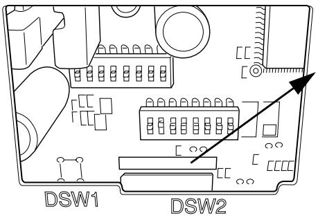
Look at the numbers and letters in the area indicated in the illustration. If the last letters are “US”, use the “US” tables below. If the last letters are “STD”, use the “STD” tables.
CAUTION:
Be sure to replace the DIP switch cover before using the printer.
US
Serial (DIP Switch 1)
| SW | Function | On | Off |
| 1 | Data receive error | Ignored | Prints “?” |
| 2 | Receive buffer capacity | 40 bytes | 4 KB |
| 3 | Handshaking | XON/XOFF | DTR/DSR |
| 4 | Word length | 7 bits | 8 bits |
| 5 | Parity check | Yes | No |
| 6 | Parity selection | Even | Odd |
| 7 | Transmission speed | 4800 bps | 9600 bps |
| 8 | BUSY condition | Receive buffer full | Receive buffer full or Offline |
Serial (DIP Switch 2)
| SW | Function | On | Off |
| 1 | Print column | 42/35 | 40/33 |
| 2 | For internal use only (autocutter) | Enabled | Disabled |
| 3 | Pin 6 reset signal | Used | Not used |
| 4 | Pin 25 reset signal | Used | Not used |
| 5 | Undefined | - | - |
| 6 | For internal use only (flash memory rewriting) | Enabled | Disabled |
| 7 | Undefined | - | - |
| 8 | Serial interface selection | Memory switch | DIP switch |
Parallel (DIP Switch 1)
| SW | Function | On | Off |
| 1 | Auto line feed | Enabled | Disabled |
| 2 | Receive buffer capacity | 40 bytes | 4 KB |
| 3~7 | Undefined | - | - |
| 8 | BUSY condition | Receive buffer full | Receive buffer full or Offline |
Parallel (DIP Switch 2)
| SW | Function | On | Off |
| 1 | Print column selection | 42/35 | 40/33 |
| 2 | For internal use only (autocutter) | Enabled | Disabled |
| 3 | Undefined | - | - |
| 4 | Pin 31 reset signal | Used | Not used |
| 5 | Undefined | - | - |
| 6 | For internal use only (flash memory rewriting) | Enabled | Disabled |
| 7 | Undefined | - | - |
| 8 | Undefined | - | - |
Serial (DIP Switch 1)
| SW | Function | On | Off |
| 1 | Data receive error | Ignored | Prints “?” |
| 2 | Receive buffer capacity | 40 bytes | 4 KB |
| 3 | Handshaking | XON/XOFF | DTR/DSR |
| 4 | Word length | 7 bits | 8 bits |
| 5 | Parity check | Yes | No |
| 6 | Parity selection | Even | Odd |
| 7 | Transmission speed | 4800 bps | 9600 bps |
| 8 | BUSY condition | Receive buffer full | Receive buffer full or Offline |
Serial (DIP Switch 2)
| SW | Function | On | Off |
| 1 | Print column | 42/35 | 40/33 |
| 2 | For internal use only (autocutter) | Enabled | Disabled |
| 3 | Undefined | - | - |
| 4 | Serial interface selection | Memory switch | DIP switch |
| 5 | Undefined | - | - |
| 6 | For internal use only (flash memory rewriting) | Enabled | Disabled |
| 7 | Pin 6 reset signal | Used | Not used |
| 8 | Pin 25 reset signal | Used | Not used |
Parallel (DIP Switch 1)
| SW | Function | On | Off |
| 1 | Auto line feed | Enabled | Disabled |
| 2 | Receive buffer capacity | 40 bytes | 4 KB |
| 3~7 | Undefined | - | - |
| 8 | BUSY condition | Receive buffer full | Receive buffer full or Offline |
Parallel (DIP Switch 2)
| SW | Function | On | Off |
| 1 | Print column selection | 42/35 | 40/33 |
| 2 | For internal use only (autocutter) | Enabled | Disabled |
| 3~5 | Undefined | - | - |
| 6 | For internal use only (flash memory rewriting) | Enabled | Disabled |
| 7 | Undefined | - | - |
| 8 | Pin 31 reset signal | Used | Not used |
TM-U220 Specifications
| Print method | 9-pin serial impact dot matrix method | |
| Print font | Font (standard) | Font A: 7 × 9, Font B: 9 × 9 |
| Column capacity (columns) | 7 × 9/9 × 9:76 mm: 40/3369.5 mm: 36/3057.5 mm: 30/25 | |
| Character size (W × H) (standard) | 1.2 × 3.1 mm/1.6 × 3.1 mm (not including horizontal spacing) | |
| Character set | 95 Alphanumeric, 48 International, 128 × 12 Graphic | |
| Characters per inch (standard)(3 half dot spacing) | Font A (7 × 9): 16 cpi, Font B (9 × 9): 13.3 cpi | |
| Paper | Dimensions (mm) | 57.5 ± 0.5, 69.5 ± 0.5,76 ± 0.5 |
| Normal paper (mm) | Thickness:0.06~0.085 (1 sheet) | |
| Pressure-sensetive paper | Thickness: 0.05~0.08 (1 sheet), total thickness must be 0.14 mm or less.Number of copies: Original 1 sheet + one copy sheet | |
| Ribbon cassettes | ERC-38 (P) Purple life: 4,000,000 charactersERC-38 (B) Black life: 3,000,000 charactersERC-38 (B/R) Black/Red life: Black 1,500,000/Red750,000 charactersLife based on continuous printing at 25°C {77°F} | |
| Print speed (Paper width 76 mm) | 4.7 lps (40 columns, 16 cpi) | |
| Interface | RS-232 or IEEE 1284 | |
| Data buffer | Receive buffer | 4 KB or 40 bytes |
| NV bit image data | 128 KB | |
| User NV memory | 8 KB | |
| Power supply | 24 VDC ± 7% | |
| Power consumption (Stand-by) | 2.2 W | |
| D.K.D. function | 2 drives | |
| Reliability (Life) | Mechanism | 7,500,000 lines |
| Print head | 150 million characters | |
| Autocutter | 800,000 cuts | |
| Temperature | Operating | 0~50°C |
| Storage | -10~50°C, without paper and ribbon cassette | |
| Humidity | Operating | 10~90%, must be no condensation |
| Storage | 10~90%, must be no condensation, without paper and ribbon cassette | |
| Overall dimensions (mm) | Type A: 160 × 286 × 157.5 (W × D × H)Type B: 160 × 248 × 138.5 (W × D × H)Type D: 160 × 248 × 138.5 (W × D × H) | |
| Mass (approx.) | Type A: 2.7 kg Type B: 2.5 kg Type D: 2.3 kg | |
DIP Switches and Specifications
The technical specifications and the information about the DIP switches are at the beginning of this manual.
Illustrations
All of the illustrations are at the beginning of this manual. They are identified by letters (A, B, C...). In the text the illustrations are referred to by these letters. ("See illustration A," for example.) Some of these illustrations have numbered arrows or lines pointing to parts of the illustration. See the list below for the meaning of the numbers.
Illustration A
- Roll paper cover
- Ribbon cassette cover
- Control panel
- Power supply switch
All rights reserved. No part of this publication may be reproduced, stored in a retrieval system, or transmitted in any form or by any means, electronic, mechanical, photocopying, recording, or otherwise, without the prior written permission of Seiko Epson Corporation. No patent liability is assumed with respect to the use of the information contained herein. While every precaution has been taken in the preparation of this book, Seiko Epson Corporation assumes no responsibility for errors or omissions. Neither is any liability assumed for damages resulting from the use of the information contained herein.
Neither Seiko Epson Corporation nor its affiliates shall be liable to the purchaser of this product or third parties for damages, losses, costs, or expenses incurred by purchaser or third parties as a result of: accident, misuse, or abuse of this product or unauthorized modifications, repairs, or alterations to this product, or (excluding the U.S.) failure to strictly comply with Seiko Epson Corporation's operating and maintenance instructions.
Seiko Epson Corporation shall not be liable against any damages or problems arising from the use of any options or any consumable products other than those designated as Original EPSON Products or EPSON Approved Products by Seiko Epson Corporation.
EPSON is a registered trademark of Seiko Epson Corporation.
NOTICE: The contents of this manual are subject to change without notice.
Copyright © 2003 by Seiko Epson Corporation, Nagano, Japan.
EMC and Safety Standards Applied
Product Name: TM-U220A/TM-U220B/TM-U220D
Model Name: M188A/M188B/M188D
The following standards are applied only to the printers that are so labeled. (EMC is tested using the EPSON power supplies.)
Europe: CE marking Safety: TÜV (EN 60950)
North America: EMI: FCC/ICES-003 Class A Safety: UL 60950/CSA C22.2 No. 60950
Japan: EMI: VCCI Class A
Oceania: EMC: AS/NZS 3548 Class B
WARNING
The connection of a non-shielded printer interface cable to this printer will invalidate the EMC standards of this device.
You are cautioned that changes or modifications not expressly approved by Seiko Epson Corporation could void your authority to operate the equipment.
This class III equipment should be used with an approved power supply with SELV outputs.
CE Marking
The printer conforms to the following Directives and Norms:
Directive 89/336/EEC EN 55022 Class B
EN 55024
IEC 61000-4-2
IEC 61000-4-3
IEC 61000-4-4
IEC 61000-4-5
IEC 61000-4-6
IEC 61000-4-11
FCC Compliance Statement For American Users
This equipment has been tested and found to comply with the limits for a Class A digital device, pursuant to Part 15 of the FCC Rules. These limits are designed to provide reasonable protection against harmful interference when the equipment is operated in a commercial environment.
This equipment generates, uses, and can radiate radio frequency energy and, if not installed and used in accordance with the instruction manual, may cause harmful interference to radio communications.
Operation of this equipment in a residential area is likely to cause harmful interference, in which case the user will be required to correct the interference at his own expense.
For Canadian Users
This Class A digital apparatus complies with Canadian ICES-003.
Important Safety Information
This section presents important information intended to ensure safe and effective use of this product. Read this section carefully and store it in an accessible location.
Key to Symbols
The symbols in this manual are identified by their level of importance, as defined below. Read the following carefully before handling the product.

WARNING:
Warnings must be followed carefully to avoid serious bodily injury.

CAUTION:
Cautions must be observed to avoid minor injury to yourself or damage to your equipment.
Safety Precautions

WARNING:
Shut down your equipment immediately if it produces smoke, a strange odor, or unusual noise. Continued use may lead to fire. Immediately unplug the equipment and contact your dealer or a Seiko Epson service center for advice.
Never attempt to repair this product yourself. Improper repair work can be dangerous.
Never disassemble or modify this product. Tampering with this product may result in injury or fire.
Be sure to use the specified power source. Connection to an improper power source may cause fire.
Do not allow foreign matter to fall into the equipment. Penetration by foreign objects may lead to fire.
If water or other liquid spills into this equipment, do not continue to use it. Continued use may lead to fire. Unplug the power cord immediately and contact your dealer or a Seiko Epson service center for advice.

CAUTION:
Do not connect cables in ways other than those mentioned in this manual. Different connections may cause equipment damage and burning.
Be sure to set this equipment on a firm, stable, horizontal surface. Product may break or cause injury if it falls.
Do not use in locations subject to high humidity or dust levels. Excessive humidity and dust may cause equipment damage or fire.
Do not place heavy objects on top of this product. Never stand or lean on this product. Equipment may fall or collapse, causing breakage and possible injury.
To ensure safety, unplug this product before leaving it unused for an extended period.
Before moving the product, unplug it and unplug all cables connected to it.
Safety Label

WARNING:
Do not connect a telephone line to the drawer kick out connector; otherwise, the printer and the telephone line may be damaged.


CAUTION:
During printing or after printing, the print head can be very hot.
Notes on Usage
☐ Do not open the cover during printing or when the autocutter is being operated.
☐ Do not install the printer in a dusty place.
☐ Protect the printer from impact.
☐ Cords or other foreign objects must not be caught on the printer.
☐ Do not apply excessive force to the printer case.
☐ Do not place food or beverages such as coffee on the case of the printer.
Notes on Installation
☐ When using the printer, be sure that the printer is installed horizontally.
☐ If you are using a Type B or D printer, you can hang it on a wall, using the optional hanging bracket set, WH-10.
Note:
To hang the printer on a wall, see the WH-10 Installation Manual for detailed instructions.
Notes on Connecting the Power Supply Unit
Be sure to use the correct power supply unit as listed below:
| TM-U220 alphanumeric model (types A, B, and D) | TM-U220 multilingual* model (types A, B, and D) |
| “AC adapter, C” (packed with the alphanumeric model) or “PS-180” (option) | “PS-180” (packed with the multilingual* model) |
Note:
The “AC adapter, C,” which is packed with the alphanumeric model, cannot be used with the multilingual* model. Be sure to use the “PS-180” with the multilingual* model. If the “AC adapter, C,” packed with the alphanumeric model, is connected to the multilingual* model by mistake, the printer might not operate correctly. For example, printing might stop before all the lines are printed or the printer might print the same line repeatedly.
*Multilingual means the printer model that can print any one of the following: Japanese Kanji, Simplified Chinese, Traditional Chinese, Thai characters, or Korean characters.
Purpose of This Manual
This manual provides information to operators of the TM-U220 to describe basic operations to enable safe and correct use of the printer.
Features of Printer Types
See illustration A.
| Type A | Type B | Type D | |
| Two color printing | Yes | Yes | Yes |
| Autocutter | Yes | Yes | No |
| Take up device | Yes | No | No |
| Paper width (mm) | 76 | 76/69.5/57.5 | 76/69.5/57.5 |
| Interface | Serial or parallel | Serial or parallel | Serial or parallel |
| Characters supported | Alphanumeric | Alphanumeric | Alphanumeric |
Illustrations
Because this manual covers three types of the TM-U220, some of the illustrations may be slightly different from your printer; however, the instructions cover all types, except as noted.
Restriction of Use
When this product is used for applications requiring high reliability/safety such as transportation devices related to aviation, rail, marine, automotive etc.; disaster prevention devices; various safety devices etc; or functional/precision devices etc, you should use this product only after giving consideration to including fail-safes and redundancies into your design to maintain safety and total system reliability. Because this product was not intended for use in applications requiring extremely high reliability/safety such as aerospace equipment, main communication equipment, nuclear power control equipment, or medical equipment related to direct medical care etc, please make your own judgment on this product's suitability after a full evaluation.
Unpacking
The following items are included for the standard specification printer. If any item is damaged, contact your dealer.
Printer
Roll paper
☐ Exclusive ribbon cassette [ERC-38(B/R)]
☐ AC adapter (May not be included with the printer.)
Control Panel (LEDs and Buttons)
See illustration B.
LEDs
POWER
Lights when the power is on and is off when the power is off.
ERROR
Lights when the printer is offline (when the roll paper is at the end, or the roll paper cover is open). Off when the printer operates correctly. Flashes when an error occurs. (See the Troubleshooting section.)
PAPER OUT
Lights when roll paper is out or nearly out.
Buttons
FEED
FEED feeds the roll paper.
Note:
Paper cannot be fed by using this button when a paper out is detected.
Power Supply Switch and Power Supply Switch Cover
The power supply switch is on the front of the printer. Press the power supply switch to turn on the printer.
Power Supply Switch Cover
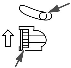
You can use the enclosed power supply switch cover to make sure that the power supply switch is not accidentally pressed. Just press the cover into place to install it. If you need to turn the power supply switch on or off with the cover attached, you can insert a thin tool into one of the holes in the cover to operate the switch. See illustration C.

WARNING:
If an accident occurs when the power supply switch cover is attached, immediately unplug the power supply cable to avoid fire.
If you are going to store the printer or leave it unused for a long time, turn it off using the power supply switch on the printer.
Inserting and Replacing the Ribbon Cassette


CAUTION:
The print head becomes very hot during printing. Allow it to cool before you replace the ribbon cassette.

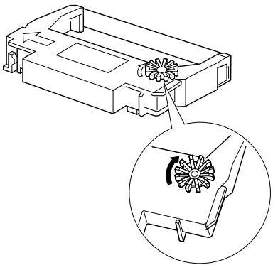
CAUTION:
Never turn the ribbon cassette's feed knob in the opposite direction of the arrow marked on the cassette; otherwise the ribbon cassette may be damaged.
Note:
Use the EPSON ERC-38 ribbon cassette for your printer.
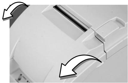
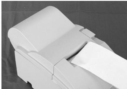
- Open the ribbon cassette cover by using the tabs on the sides of the cover, as shown in illustration D.
- Turn the knob two or three times in the direction of the arrow, as shown in illustration E.
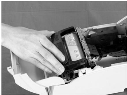
- Insert the ribbon in the position shown in illustration F and push the ribbon cassette down until it clicks.
Note:
Make sure the ribbon is installed between the print head and the platen without wrinkles or creases.
- Again turn the ribbon cassette's knob 2 or 3 times in the direction of the arrow and close the ribbon cassette cover.


CAUTION:
Be careful not to touch the print head with your fingers when turning the ribbon cassette knob because the print head is hot and you might be burned.
When you replace the ribbon cassette, lift the left side of the ribbon cassette first; then lift the whole ribbon cassette.
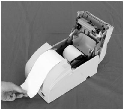
Inserting Roll Paper

CAUTION:
Be sure to use roll paper that meets the specifications.
Be sure not to touch the manual cutter. Otherwise your fingers might be injured.
-
Using scissors, cut the leading edge of the roll paper, as shown in illustration G.
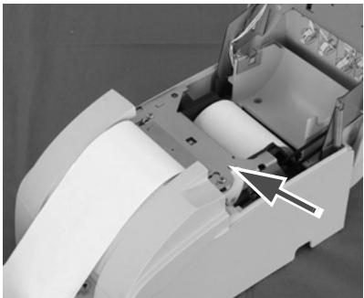
-
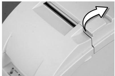
Turn on the printer and open the roll paper cover by using the tab, as shown in illustration H.
-
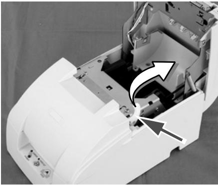
Type A only: Open the unit by using the unit open lever, as shown in illustration I.
-
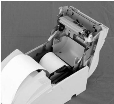
Insert the roll paper, as shown in illustration J.
Note:
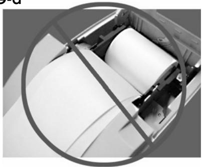
Note the direction the paper comes off the roll, as shown in the illustration G.
When using 2-ply roll paper, be sure that the top and bottom sheets are aligned at the paper exit. See illustration G-a.
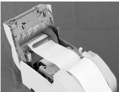
-
If you are not using a take-up spool, pull out a small amount of roll paper and close the roll paper cover; then tear off the paper with the manual cutter. You can skip steps 6 through 11.
-
Type A only: When using 2-ply roll paper, pull out the roll paper to the bottom front of the printer as a guide, as shown in illustration K.
-
Close the unit, as shown in illustration L.
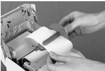
-
Insert the end of the bottom paper (journal paper) into the paper take-up spool, as shown in illustration M.
-
Insert the paper take-up spool in the printer. Be sure that the paper is aligned with the spool's flange, as shown in illustration N.
-
Feed the paper with the FEED button so that the paper is taken up by the spool.
-
Close the roll paper cover and tear off the roll paper with the manual cutter, as shown in illustration O.
Note:
Do not open the roll paper cover during printing or paper feeding.
When using the printer, be sure to cut the roll paper with the manual cutter after paper feeding is complete.
Replacing Roll Paper
-
Open the roll paper cover by using the tab, as shown in illustration H.
-
Types B and D: Remove the used roll paper core.
-
Type A only: Remove the take-up spool, and open the unit by using the unit open lever, as shown in illustration I; then remove the used roll paper core.
-
Insert new roll paper. See the section "Inserting Roll Paper".
Troubleshooting
Printing stops before all the lines are printed or the printer prints the same line repeatedly
If the correct power supply unit is not used, the printer cannot operate correctly. Make sure the correct power supply unit is connected to the printer, referring to the table below:
| The power supply unit that can be used with the TM-U220 alphanumeric model (types A, B, and D) | The power supply unit that can be used with the TM-U220 multilingual* model (types A, B, and D) |
| “AC adapter, C” (packed with the alphanumeric model) or “PS-180” (option) | “PS-180” (packed with the multilingual* model) |
*Multilingual means the printer model that can print any one of the following: Japanese Kanji, Simplified Chinese, Traditional Chinese, Thai characters, or Korean characters.
No lights on the control panel
☐ Check the power supply cable connections and the power outlet.
ERROR LED is flashing or lit
☐ The print head temperature may be too high or low. Wait until the print head cools or warms and the printer resumes printing automatically.
☐ Make sure that the roll paper cover is properly closed.
☐ Types A and B: The autocutter blade is not in the normal position and the autocutter is locked up. If it is a simple lock-up, the error is corrected automatically. If not, see the instructions below to return the blade to the normal position manually.
☐ A paper jam has occurred. To remove the jammed paper, see the instructions below.
☐ Be sure to check if the specified power source is used. PA-6xxx and PB-6xxx cannot be used with this printer.
☐ Turn off the power, wait several seconds, and then turn it on again. If the error remains, contact your supervisor or a qualified service person.
Returning the autocutter blade to the normal position
- Open the roll paper cover by using the tab, as shown in illustration H.
- Use a ballpoint pen or tweezers to turn the knob of the autocutter in the direction indicated by the arrow until you see a round shaft in the hole, as shown in illustration P.
Removing jammed paper


CAUTION:
The print head becomes very hot during printing. Allow it to cool before you reach into the printer.
- Open the roll paper cover by using the tab, as shown in illustration H.
- If you have a Type A printer, remove the take-up spool and open the unit by using the unit open lever, as shown in illustration I.
- Remove the jammed paper.
- Re-insert the roll paper and close the roll paper cover.
EPSON Ecology Label
This product is in compliance with the EPSON ecology label requirements. Please see the following link for detailed information on label criteria. (http://www.epson.co.jp/e/)

TM-U220 Drucker
Bedienungsanleitung
Copyright © 2003 Seiko Epson Corporation, Nagano, Japan.
Typenname: M188A/M188B/M188D
TM-U220 Printers
Copyright © 2003 by Seiko Epson Corporation, Nagano, Japan.
Imprimantes TM-U220
Impressoras TM-U220
Manual do utilizador
© 2003 Seiko Epson Corporation, Nagano, Japão
Impresoras TM-U220
Manual del usuario
Stampanti TM-U220
Manuale dell'utente
Copyright © 2003 Seiko Epson Corporation, Nagano, Giappone.
TM-U220
WEEE (Waste Electrical and Electronic Equipment) Directive
This information only applies to customers in the European Union, according to Directive 2002/96/EC OF THE EUROPEAN PARLIAMENT AND OF THE COUNCIL OF 27 January 2003 on waste electrical and electronic equipment (WEEE) and legislation transposing and implementing it into the various national legal systems.
For other countries, please contact your local government to investigate the possibility of recycling your product.

English
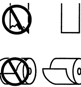
The crossed out wheeled bin label that can be found on your product indicates that this product should not be disposed of via the normal household waste stream. To prevent possible harm to the environment or human health please separate this product from other waste streams to ensure that it can be recycled in an environmentally sound manner. For more details on available collection facilities please contact your local government office or the retailer where you purchased this product.
Deutsch
Printed on Recycled Paper
Printed in China
2003.04