
UFO 30 - Audio/video converter KATHREIN - Free user manual and instructions
Find the device manual for free UFO 30 KATHREIN in PDF.


| Product Type | Audio/Video Converter |
| Brand | Kathrein |
| Model | UFO 30 |
| Dimensions (W x H x D) | 180 mm x 130 mm x 50 mm |
| Weight | 500 g |
| Power Supply | 12V DC, 1A |
| Input Interface | HDMI |
| Output Interface | HDMI |
| Supported Audio Formats | PCM, Dolby Digital, DTS, AAC |
| Supported Video Resolutions | 720p, 1080i, 1080p |
| Video Scaling | Up to 1080p |
| Audio Sampling Rate | Up to 192 kHz |
| Operating Temperature | 0°C to 40°C |
| Storage Temperature | -20°C to 60°C |
| Relative Humidity | 10% to 90% (non-condensing) |
| Housing Material | Metal |
| Maintenance | Wipe with a dry, soft cloth; avoid liquids |
| Safety Precautions | Do not open the device; avoid exposure to moisture |
| Spare Parts Availability | Contact Kathrein support for replacement parts |
| Repairability | Repair only by authorized service personnel |
Frequently Asked Questions - UFO 30 KATHREIN
User questions about UFO 30 KATHREIN
0 question about this device. Answer the ones you know or ask your own.
Ask a new question about this device
Download the instructions for your Audio/video converter in PDF format for free! Find your manual UFO 30 - KATHREIN and take your electronic device back in hand. On this page are published all the documents necessary for the use of your device. UFO 30 by KATHREIN.
USER MANUAL UFO 30 KATHREIN
As of 1 April 2019, KATHREIN SE's (formerly KATHREIN-WERKE KG) "Terrestrial & Satellite Reception" business unit will be transferred to KATHREIN Digital Systems GmbH (limited liability company).
From 1 April 2019, the new company data are:
KATHREIN Digital Systems GmbH
Anton-Kathrein-Str. 1-3
83022 Rosenheim, Germany
Tax ID No.: 156/117/31083
■ Standalone Head-End 8x DVB-S(2)-QAM
■ Converts eight QPSK/8PSK-modulated DVB-S(2) signals into eight adjacent QAM-modulated DVB-C output signals
■ TV channels preprogrammed
■ Outstanding data through direct implementation as FPGA solution
■ High energy efficiency, power consumption: Typ. 25 W
■ Two SAT IF inputs A/B, adjustable independently of each other via the central controller
■ All the transmission parameters can be set with the USW 30 management program
■ MPEG transport stream processor:
- to set a constant output data rate (stuffi ng) with PCR correction
– with channel filter to blank out TV and radio channels
■ Fanless design for wall mounting (no noise)

Function blocks
![graph TD A["Eingang"] --> B["2 x 8 Matrix 8 x DVB-S/-S2 8 x DVB-C"] C["Frontend Basisband Ausgang"] --> D["Programm-Filter"] C --> E["CAT-Anpassung"] F["Block-Umsetzung"] --> G["..."]](/content/2026/05/1030107/images/c4461b41a5ff58fc1991bea27fe9361a13e1c51d413df71560ca332f27d93fd3.jpg)

Note
The most up-to-date version of these user instructions can be found on the Kathrein homepage under www.kathrein.com → SAT → Product overview → Signal processing/conversion → Channel units. The information about the UFO 30 can be downloaded from the product page.
Technical Specifications
| Type UFO 30 | ||
| Input | ||
| Sat IF input 2 x F connector/75 Ω | ||
| Frequency range MHz 950 ... 2150 | ||
| Decoupling dB Min. 25 | ||
| Return loss dB Typ. 6 | ||
| Frontend | ||
| DVB-S2 8 x | ||
| Frequency grid 1 (950 ... 2150 MHz) | ||
| AFC regulation range | MHz | ±3 (symbol rate < 10 Ms/s) ±5 (symbol rate > 10 Ms/s) (950 ... 2150 MHz) |
| Input level range dBμV 60 ... 110 | ||
| Permissible level difference dB | 12 | |
| Demodulation DVB-S | ||
| Standard | EN 300 421 (1) | |
| Input symbol rate QPSK | MS/s | 2 ... 45 |
| Code rate (Viterbi) | 1/2, 2/3, 3/4, 5/6, 7/8 | |
| Roll off | % | 35 |
| Demodulation DVB-S2 | ||
| Standard | EN 302 307 (2) | |
| Input symbol rate QPSK | MS/s | 1 ... 34 |
| Code rate (LDPC) | 1/2, 3/5, 2/3, 3/4, 4/5, 5/6, 8/9, 9/10 | |
| Input symbol rate 8PSK | MS/s | 1 ... 31.5 |
| Code rate (LDPC) | 3/5, 2/3, 3/4, 5/6, 8/9, 9/10 | |
| Roll off | % | 20/25/35 |
| MPEG-TS processor | ||
| Channel filter | ✓ | |
| PID filter | ✓ | |
| PSI/SI processing | PCR correction | |
| Stuffing | Automatic | |
| QAM modulator | ||
| Output channels | 8 x DVB-C (J.83A) as adjacent channels | |
| QAM constellation | QAM | 16, 32, 64, 128, 256 |
| Symbol rate | MS/s | 1.5 ... 7.15 |
| Roll off | % | 15 |
| HF output | ||
| DVB-C output | 1 x F connector/75 Ω | |
| Frequency range MHz | 110 .. 862 (fine-tuning in 250 kHz steps) | |
| Frequency range (channel list) | MHz | 110 .. 862 (setting via channel list) |
| Return loss dB | 14 (47 MHz) - 1.5 dB/oct. | |
| Output level | dBμV | 91 |
| Output level setting range | dB | -20 (in 0.5-dB steps) |
| Level stability | dB | Typ. ±0,5 |
| Frequency stability | ppm | Typ. 35 |
| MER | dB | Typ. ≥ 45 |
| Shoulder attenuation | dB | ≥ 60 (at normal level) |
| Spurious emissions | dB | ≥ 60 |
| System data | ||
| Power consumption | W | Typ. 25 |
| Temperature range | °C | 0 ... 40 |
| Dimensions (H x W x D) | mm | 282.5 x 249.5 x 61.0 |
| Weight | kg | 2.5 |
Setting up
Mounting
- Choose the mounting location with regard to the minimum clearances to avoid a build-up of heat; see Fig. 1.
- Mount the screws with dmax = 4 mm and do not do them up tightly; see Fig. 2 and the attached drilling template.
- Install the equipotential bonding in accordance with the regulations (cable shoe).
- Suspend the UFO 30 and do the screws up tightly.
- If required, fi t F-type connectors to the HF connecting cables; see Fig. 3.
- Connect the HF connecting cables in accordance with the system planning.
- Close 3 drill holes in the cover plate by means of the enclosed caps.

Fig. 1: Clearances to containing surfaces Fig. 2: Dimensions and installation dimensions
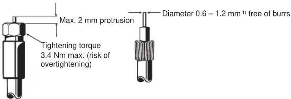
Fig. 3: Attachment of the F-type connector
1) If the cable inner conductor diameter is greater than 1.2 mm, or in the case of burrs, the device sockets may be damaged beyond repair.
Safety instructions

WARNING
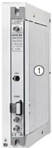
Danger of burns from hot surfaces. Caution when touching the heat sink(① in the figure on the right).
If there is a defect the heat sink of the unit can exceed 70\ °C . In such a case the unit normally switches itself off. Take the corresponding care when working with the unit under such conditions.
Operation
The operation of the unit is done via the graphic user interface of the USW 30 control program.
Note
The current version of USW 30 and its operating instructions can be downloaded free from the Kathrein homepage www.kathrein.com.
Licences
This product contains among other things software components that are subject to Open Source licenses. The license texts and the source code of the programs can be found under http://www.kathrein.de/gpl/ufocompact/ufo30.
Setup instructions
The Plug-and-Play delivery status allows the operation of the UFOnano head-unit without any further configuration. After mounting and connection 78 TV and 9 radio channels are available at once (via Astra 19.2° east, transponder allocation as of Q3/2014; see Tab. 1).
Any changes to the default configuration are made using the USW 30 control program. For programming the head-unit must be connected with the programming cable UFZ 30, BN 20410058 (not supplied with the unit) and a PC with a USB connection.
| Chan- nel unit | Input Transponder/channel | SD/ HD | Band | Polariza- tion | Transp.- frequency | Sat IF/ MHz | SR | Stan- dard | CR | Output channel | Symbol rate | Output level | QAM |
| 1 A Das Erste, BR, HR, SWR, WDR | SD | High Horizontal | 11836 | 1236 | 27500 | DVB-S | 3/4 | S21 6.9 | -2 64 | ||||
| 2 A ZDF, 3sat, KIKA, ZDFinfo, ZDFkultur, ZDF neo | SD | High Horizontal | 11954 | 1354 | 27500 | DVB-S | 3/4 | S22 6.9 | -2 64 | ||||
| 3 A MDR, NDR, RBB, SWR SD | High Horizontal | 12110 | 1510 | 27500 | DVB-S | 3/4 | S23 6.9 | -2 64 | |||||
| 4 A RTL, N-TV, RTL2, RTL Living, RTLnitro, Vox | SD | High Horizontal | 12188 | 1588 | 27500 | DVB-S | 3/4 | S24 6.9 | -2 64 | ||||
| 5 A Pro Sieben, Sat1, Kabel eins, N24... | SD | High Horizontal | 12545 | 1945 | 22000 | DVB-S | 5/6 | S25 6.9 | -2 64 | ||||
| 6 A Anixe, Das Vierte, 1-2-3 TV, TLC Germany, Sixx Deutschland | SD High Horizontal 12460 1860 27500 DVB-S 3/4 S26 6.9 -2 64 |
| 7 B VIVA, Nickelodeon... SD High Vertical 11973 1373 27500 DVB-S 3/4 S27 6.9 -2 64 | |
| 8 B Sport1, DMAX, HSE24, SonnenklarTV, Astro TV... | SD High Vertical 12480 1880 27500 DVB-S 3/4 S28 6.9 -2 64 |
Tab. 1: Delivery status UFO 30, transponder Astra 19.2° east and output channel assignment
Notes
- The setting and numeric values given in the following are only examples and may not necessarily match the delivery status.
- Additional preset configurations are available for the operation of two UFOnano units or for reception from other satellites. These can be downloaded free from the Kathrein homepage www.kathrein.com.
- When operating two UFOnano units ensure that the relevant output blocks do not overlap. The output signals of the two head-units can then be combined with distributors of the EBC series; see the example in Fig. 4.
- The power supply of the LNB (remote feeding) must be done with external components. It is recommended to use the VWS 2500 multi-switch distribution network amplifier (Fig. 4). In addition, optimal signal processing is assured for the VWS 2500 through individual amplification and slope range settings.
Pay attention to the input level of the UFO 30 and, if necessary, verify it using a meter. Alternatively, it is possible to adjust settings on the VWS 2500 as guide values from the following table:
| For cable lengths from UFO 30 to LNB | < 25 m | 25 m – 50 m | 50 m – 75 m | >75 m |
| ATTENUATION | 12 | 8 | 4 | 0 |
| PREEMPHASE | 2 | 4 | 6 | 6 |
A remote feed diplexer (e.g. WFS 31) and a power supply unit (e.g. NCF 18) can be used for the LNB supply.
![graph TD A["UAS 584"] --> B["VWS 2500"] C["Sat-ZF 950-2150 MHz"] --> B B --> D["Sat-ZF"] D --> E["UFO 30"] E --> F["EBC 02"] F --> G["UFO 30"] G --> H["Sat-ZF"] H --> I["UFO 30"] I --> J["EBC 02"]](/content/2026/05/1030107/images/decb6657e979a6864c7290f9ffacf4f90f2d950fb97215077878bff5c2b71984.jpg)
Fig. 4: Combination of two UFOnano with one EBC 02
Configuration
1. Reading the system
A connection to a UFOnano can be established by the menu item (System | Read out system|) or by clicking on the respective symbol in the symbol bar. The following dialogue that offers the following options to establish a connection then appears:

Select Channel Unit | UFOnano for the connection with a UFOnano head-unit. The configuration window appears after a successful connection.
2. Basic settings
All the configurable parameters of a module, such as the input and output frequencies, can be set using the Basic Settings window.
Non-configurable parameters (such as SNR, BER, code rate), which represent continually varying status information regarding the head-end, are read at intervals of about 3 seconds and updated in the dialogue window.
![UFO J0 [V01] Basic Settings Program Table PID List Channel Unit 1 Input Input Input A Lock Status Locked Satellite Astra (19,2 east) Mode DVBS/QPSK Transponder 11,836.0 MHz, ARD Digit... Code rate 3/4 Sat-Frequency 11,836 MHz SNR 17.0 dB ZF frequency 1,236 MHz BER < 1E-7 Symbol rate 27.500 MS/s Data…](/content/2026/05/1030107/images/5d3a1b4ad21ef287787732183132c0c61bc39285a03348e4f688095c64eba3cc.jpg)
The display always refers to one of the eight channels in the head-end. First select the channel 1 to 8 for which you wish to change the settings.
2.1 Input configuration
| Input | The socket A or B to be used for the input can be selected in the selection box Input for the selected channel unit. |
| Satellite | In the Satellite selection box a known satellite can be selected from the USW 30 satellite list. |
| Transponder | The Transponder selection box contains a list of transponders that are available at the connected selection plane of the selected input. The precondition for this is that the transponders are given in the satellite list.The selection of a transponder automatically sets the values for the Sat-Frequency, ZF frequency and Symbol rate.In addition, the following search dialogue for channels and transponders can be activated by the button to the right next to the selection box: |
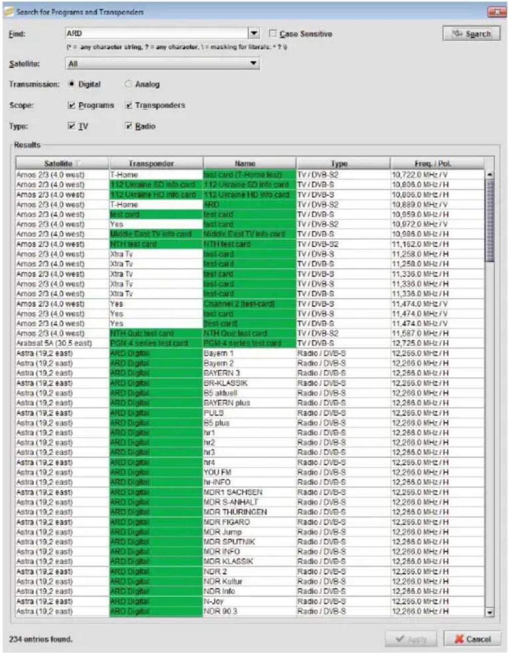
Using Store for a set of selected search results, transponders and the associated frequencies and the symbol rates are filled in accordingly. Alternatively, the Sat-Frequency/ZF frequency and Symbol rate can also be input manually, e.g. if a particular transponder is not included in the list of satellites.
If a valid DVB-S/S2 transport stream is received on the set frequency, then the Lock Status is set to Locked. The text boxes Mode, Coderate, C/N Reserve, SNR and BER show in this case information on the properties and quality of the received satellite signal.
Note
The satellite frequency and IF frequency depend directly on one another and are converted automatically.
2.2 Data stream confi guration
In the Basic Settings | Data stream area the basic settings for the processing of the transport stream of a channel unit can be configured. The channel filter and PID filter function can be switched on and off at the corresponding selection boxes.
| NIT | The NIT text box shows that the NIT (Network Information Table) has been taken over unchanged (NIT Original). |
| CAT | There is the option to replace the CAT. The CAT (Conditional Access Table) is generally taken from the satellite transport stream. In special cases, such as for provider KabelKiosk, it can be necessary to replace the CAT Operator ID in the transport stream (mark the checkbox Insert Operator ID in CAT). The new value for the CAT Operator ID can be changed manually (field Operator ID) and is then inserted into the transport stream in place of the original ID. |
| Load | In the Load text box the current and peak loads of the output are shown in %. The measured value for peak loading can be reset with the button to the right.If the loading reaches values of over 90 % the text colour changes to red. This indicates that any further loading through additional channels would exceed the capacity of the output channels. |
2.3 DVB-C-QAM output configuration
In the Basic Settings | Output area the QAM output of the head-unit can be configured.
| HF output | Using the HF Output selection box the HF output of the channel unit can be switched on and off. |
| Channel | The Channel selection box describes a normal cable standard channel grid of K21-K69 and S21-S41 in steps of 8 MHz. |
| Frequency | A fi ne setting of the frequency can be done manually in the text box in steps of 0.25 MHz. |
| Symbol rate | The fi ne setting of the symbol rates can be done manually in the corresponding text box in steps of 1 KS/s. |
| Level | Using the Level selection box the signal strength of the output signal can be set in 40 steps from maximum (0) to minimum (-40). |
| Constellation | The selection box Constellation specifi es the QAM constellation (QAM16, QAM32, ..., QAM256). |
| Mode | The selection box Mode allows the HF output to be modulated with various output signals, for example, for measuring and analysis purposes:In the normal operating mode the transmodulated satellite signal is output.PRBS: Test mode. The QAM signal is modulated with the PRBS-23 sequence. Normal mode is unavailable in this setting.CW: Test mode. Sine-wave signal for levelling using simple signal meters. Normal mode is unavailable in this setting. |
2.4 Channel table/fi Iter configuration
![UFO 30 [V01] Basic Settings Program Table PID List Channel Unit 1 No. Name SID Type Active 1 SWR Fernsehen BW 0x6DD1 TV □ 2 Bayerisches FS Sued 0x6DCB TV □ 3 Das Erste 0x6DCA TV □ 4 hr-termsehen 0x6DCC TV □ 5 WDR Köln 0x6DCF TV □ 6 Bayerisches FS Nord 0x6DCE TV □ Undo Store OK](/content/2026/05/1030107/images/503b48b8fa37401c3afe83dff07a99dc21f4c1da93ff70d86f490305fceb89a3.jpg)
The channel table includes all the channels (services) of a channel unit. The table contains the service IDs and channel types in addition to the names of the channels. The entry in the Active column for each channel specifies whether it should be included in the output transport stream.
2.5 PID list
![UFO 30 [V01] Basic Settings Program Table PID List Channel Unit 1 The PIDs have to be written in hexadecimal format (without the leading "0x"). No. PID Action Add Delete Delete All Undo Store OK](/content/2026/05/1030107/images/37e61c42da0f4325f0f9168fe5eeb7550916f77c3fe5167d29ac968993ff7a86.jpg)
In the PID list the package IDs (package IDs/PIDs) which are always allowed through by the filtering can be specified in addition to the channel table. The PID list is required only in exceptional cases. Please note that the maximum length of the PID list is limited (e.g. to 100 entries). The maximum length can vary depending on the firmware version.
2.6 Software Configuration
General settings can be made in the menu Settings | Basic Settings. Within the individual tabs a variety of settings can be performed. They can also be called up by the Settings button to the right of the ZF frequency row.
2.6.1 Interface settings
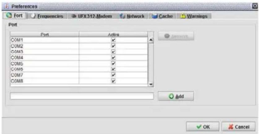
In the upper part of the dialogue window the ports required for communication with the UFOnano systems can be activated:
- Select interface: Mark the checkbox of the interface.
- Delete interface: Select the interface with the left mouse button and press the Remove button.
New interfaces can be added underneath the list of existing interfaces. If the UFOnano system has been connected with the PC, for example, via interface COM9, then enter COM9 in the text field and press the Add button. The new interface will immediately be added to the list.
2.6.2 Frequency settings

The values for the LO frequency and the frequency for automatic changeover of the desired frequency band depend on your satellite system, and in particular on the configuration of the LNB or a satellite matrix. The frequencies can be config-
ured separately for each satellite. The Automatically update the DiSEqC option is not used in the UFOnano.
2.6.3 UFX 312 modem confi guration

The UFX 312 modem configuration has no influence on the UFOnano settings. Please note the item Setup instructions regarding this.
2.6.4 Network
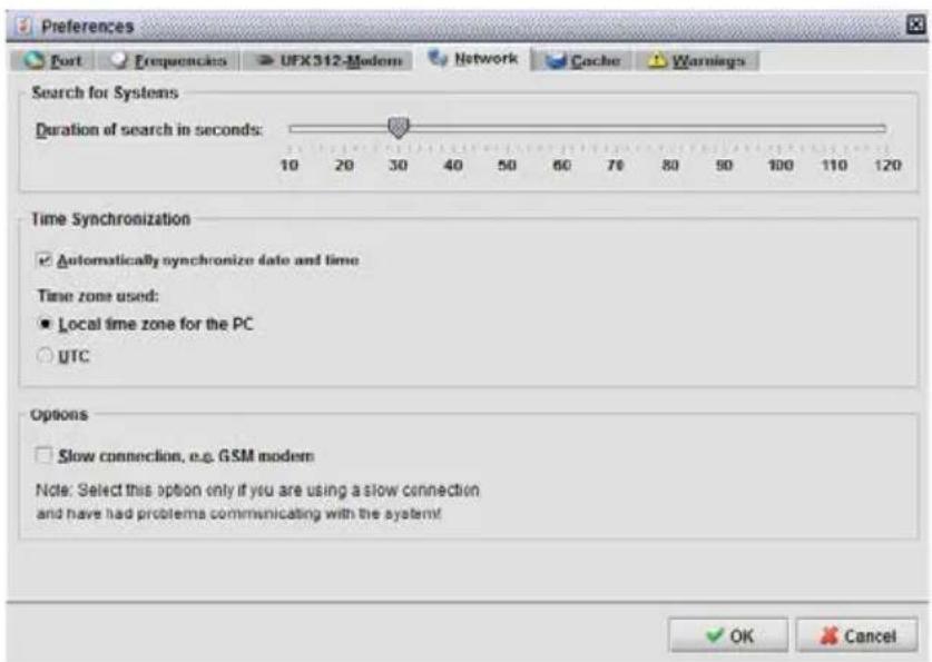
The network configuration has no influence on the UFOnano settings.
2.6.5 Cache
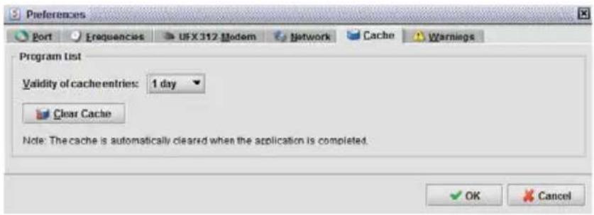
In the Cache tab you can perform settings for the channel units cache.
When the channel list for a transponder or DVB-T channel is being read in by a channel unit, this channel list can be saved in the background. If this or another channel unit should read in the channel list for the same transponder then the saved channel list is used instead. When using the same transponder successively, this can significantly reduce the waiting times.
Validity of cache entries Since the channel list of a transponder can change, it makes sense to rewrite the information saved in the background from time to time. This interval can be configured by setting the Validity of cache entries.
Clear cache There is also the option to clear the cache immediately. This is particularly useful if you know that the channel list for a transponder has changed. If you are unsure whether a channel list is still current, clear the transcoder cache and read in the transponder afresh. On quitting the application, the cache for the channel units is cleared automatically.
2.6.6 Warnings

The Warnings tab is not relevant for operation of the UFOnano. It is not possible to accidentally make a multiple assignment of the output frequencies due to the block implementation.

Electronic equipment is not household waste! In accordance with directive 2002/96/EC OF THE EUROPEAN PARLIAMENT AND THE COUNCIL dated 27th January 2003 on used electrical and electronic equipment, it must be disposed of properly.
At the end of its service life, take this receiver for disposal at a designated public collection point.
936.4781/b/VMPT/0715/GB – Subject to technical changes!
936.4781/b/VMPT/0715/DE-GB


- FUNCTION BLOCKS
- NOTE
- SETTING UP
- MOUNTING
- SAFETY INSTRUCTIONS
- WARNING
- OPERATION
- LICENCES
- SETUP INSTRUCTIONS
- NOTES
- CONFIGURATION
- READING THE SYSTEM
- BASIC SETTINGS
- 2.1 INPUT CONFIGURATION
- 2.2 DATA STREAM CONFI GURATION
- 2.3 DVB-C-QAM OUTPUT CONFIGURATION
- 2.4 CHANNEL TABLE/FI ITER CONFIGURATION
- 2.5 PID LIST
- 2.6 SOFTWARE CONFIGURATION
- 2.6.1 INTERFACE SETTINGS
- 2.6.2 FREQUENCY SETTINGS
- 2.6.3 UFX 312 MODEM CONFI GURATION
- 2.6.4 NETWORK
- 2.6.5 CACHE
- 2.6.6 WARNINGS
Brand : KATHREIN
Model : UFO 30
Category : Audio/video converter