HDV-HDMI-RZ - Audio/video extender Black Box - Free user manual and instructions
Find the device manual for free HDV-HDMI-RZ Black Box in PDF.


| Product Type | Audio/video extender |
| Brand | Black Box |
| Model | HDV-HDMI-RZ |
| Supported Resolution | 1080p (1920x1080) @60Hz |
| Maximum Transmission Distance | 50 meters over Cat6 cable |
| Input Interface | HDMI (Type A, female) |
| Output Interface | HDMI (Type A, female) |
| Power Supply | 5V DC, 1A (adapter included) |
| Power Consumption | <3W |
| Dimensions (W x D x H) | 100 x 75 x 25 mm |
| Weight | 200 g |
| Color | Black |
| Operating Temperature | 0°C to 50°C |
| Compliance | HDMI 1.3, HDCP 1.2 |
| Key Features | Plug-and-play, supports IR pass-through, LED status indicators |
| Maintenance | Wipe with a soft, dry cloth. Do not use liquid cleaners. |
| Safety | Avoid exposure to moisture and extreme temperatures. |
| Repairability | Not user-serviceable. Contact Black Box support for repairs. |
| Package Contents | Extender unit, power adapter, manual |
| Warranty | 1 year limited warranty |
Frequently Asked Questions - HDV-HDMI-RZ Black Box
User questions about HDV-HDMI-RZ Black Box
0 question about this device. Answer the ones you know or ask your own.
Ask a new question about this device
Download the instructions for your Audio/video extender in PDF format for free! Find your manual HDV-HDMI-RZ - Black Box and take your electronic device back in hand. On this page are published all the documents necessary for the use of your device. HDV-HDMI-RZ by Black Box.
USER MANUAL HDV-HDMI-RZ Black Box
HD View HDMI Transmitter and Receiver
Extend real-time, full-HD digital media over ordinary CATx cable—and communicate via IP with remote Ethernet peripherals.
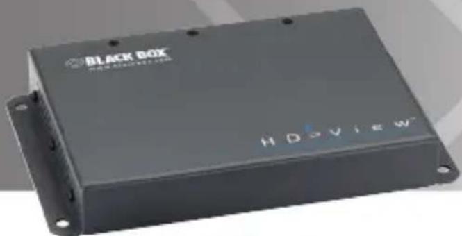
natural_image
Exterior view of a black Box electronic device (no visible text or symbols on body)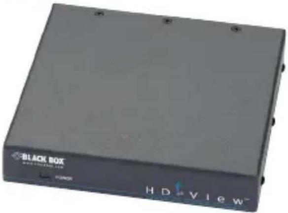
natural_image
Exterior view of a black Box electronic device (no visible text or symbols on body)FEDERAL COMMUNICATIONS COMMISSION AND INDUSTRY CANADA RADIO FREQUENCY INTERFERENCE STATEMENTS
This equipment generates, uses, and can radiate radio-frequency energy, and if not installed and used properly, that is, in strict accordance with the manufacturer's instructions, may cause interference to radio communication. It has been tested and found to comply with the limits for a Class A computing device in accordance with the specifications in Subpart B of Part 15 of FCC rules, which are designed to provide reasonable protection against such interference when the equipment is operated in a commercial environment. Operation of this equipment in a residential area is likely to cause interference, in which case the user at his own expense will be required to take whatever measures may be necessary to correct the interference.
Changes or modifications not expressly approved by the party responsible for compliance could void the user's authority to operate the equipment.
This digital apparatus does not exceed the Class A limits for radio noise emission from digital apparatus set out in the Radio Interference Regulation of Industry Canada.
Electrical Safety Statement
Trademarks Used in this Manual
Black Box and the Double Diamond logo are registered trademarks of BB Technologies, Inc.
Any other trademarks mentioned in this manual are acknowledged to be the property of the trademark owners.
Contents
ChapterPage
- Specifications....7
- Overview 8
2.1 Introduction....8
2.2 Features 8
2.3 What's Included 8
2.4 Hardware Description....10
2.4.1 Transmitter....10
2.4.2 Receiver.... 11
- Installation 12
3.1 Compatible Cabling.... 12
3.2 Pre-Installation Guidelines....12
3.3 Media Distribution.... 12
3.3.1 Connecting the Player and the Screen 14
3.3.2 Connecting the System Cable 14
3.3.3 Connecting to the Power Supply.... 14
3.3.4 Mounting the Receiver 14
- Operation 15
4.1 Serial Control.... 15
4.2 Terminal IP Connectivity 16
4.3 Scalability.... 17
1. Specifications
Maximum Resolution — HDV-HDMI-TZ-K, HDV-HDMI-TZ, HDV-HDMI-RZ-K, HDV-HDMI-RZ: 1080p, 60 Hz, 24-bit per pixel, uncompressed
Mounting — VESA
MTBF — 400,000 hours
Speed — 100 Mbps Ethernet (for network ports only)
Connectors — HDV-HDMI-TZ-K, HDV-HDMI-TZ: (1) 1.65-mm connector for DC power, (1) DB9 serial, (1) RJ-45 for Ethernet, (1) DisplayPort, (1) HDMI, (1) RJ-45 for System; HDV-HDMI-RZ-K, HDV-HDMI-RZ: (1) 1.65-mm connector for DC power, (1) 3.5-mm connector, (1) RJ-45 for System, (1) HDMI, (1) RJ-45 for Ethernet, (1) DB9 serial
Indicators — HDV-HDMI-TZ-K, HDV-HDMI-TZ: (3) LEDs: (1) Power, (1) Ethernet, (1) System; HDV-HDMI-RZ-K, HDV-HDMI-RZ: (2) LEDs: (1) Ethernet, (1) System
Temperature Tolerance — Operating: 32 to 104°F (0 to 40°C); Storage: -40 to +185°F (-40 to +85°C)
Power — HDV-HDMI-TZ-K, HDV-HDMI-TZ, HDV-HDMI-RZ-K, HDV-HDMI-RZ: Each has (1) 12-VDC, 2-A power supply; Consumption: HDV-HDMI-TZ, HDV-HDMI-TZ-K: 5 W; HDV-HDMI-RZ-K, HDV-HDMI-RZ: 7 W
Size — HDV-HDMI-TZ-K, HDV-HDMI-TZ: 1.6"H x 5.4"W x 5.5"D (4 x 13.9 x 14 cm); HDV-HDMI-RZ-K, HDV-HDMI-RZ: 1.1"H x 7.5"W x 4.8"D (2.7 x 19 x 12.3 cm)
Weight — HDV-HDMI-TZ-K, HDV-HDMI-TZ, HDV-HDMI-RZ, HDV-HDMI-RZ-K: 0.8 lb. (0.36 kg) each unit
2. Overview
2.1 Introduction
The HD View ^™ HDMI Transmitter and Receiver system delivers real-time digital non-compressed content to digital signage terminals up to 2000 feet (300 m) away (when cascaded).
2.2 Features
The HD View HDMI offers the following high-level capabilities:
• Media distribution
- Display serial control
• Terminal IP connectivity
- Scalability
2.3 What's Included
Your package should include the following items. If anything is missing or damaged, contact Black Box Technical Support at 724-746-5500 or info@blackbox.com.
HDV-HDMI-TZ-K:
• HD View HDMI Transmitter
- Power adapter
- This user's manual
HDV-HDMI-RZ-K:
• HD View HDMI Receiver
- Power adapter
- This user's manual
HDV-HDMI-TZ:
• HD View HDMI Transmitter
- 5-foot (1.5-m) HDMI cable, male/male black jacket
- 6-foot (1.8-m) CAT5 cable, 24 AWG
- 6-foot (1.8-m) DisplayPort cable
- DB9 serial cable
- Power adapter
- This user's manual
HDV-HDMI-RZ:
• HD View HDMI Receiver
- 5-foot (1.5-m) HDMI cable, male/male black jacket
- 6-foot (1.8-m) CAT5 cable, 24 AWG
• 3.5-mm monitoring cable
- DB9 serial cable
- Power adapter
- This user's manual
HDV-HDMI-TZ-A-K:
- 5-foot (1.5-m) HDMI cable, male/male black jacket
- 6-foot (1.8-m) CAT5 cable, 24 AWG
- 6-foot (1.8-m) DisplayPort cable
- DB9 serial cable
HDV-HDMI-RZ-A-K:
- 5-foot (1.5-m) HDMI cable, male/male black jacket
- 6-foot (1.8-m) CAT5 cable, 24 AWG
• 3.5-mm monitoring cable - DB9 serial cable
2.4 Hardware Description
2.4.1 Transmitter
Figures 2-1 and 2-2 show the transmitter's front and back panels. Table 2-1 describes its components.
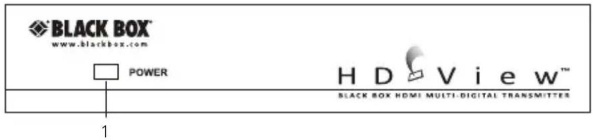
Figure 2-1. HDV-HDMI-TZ front panel.
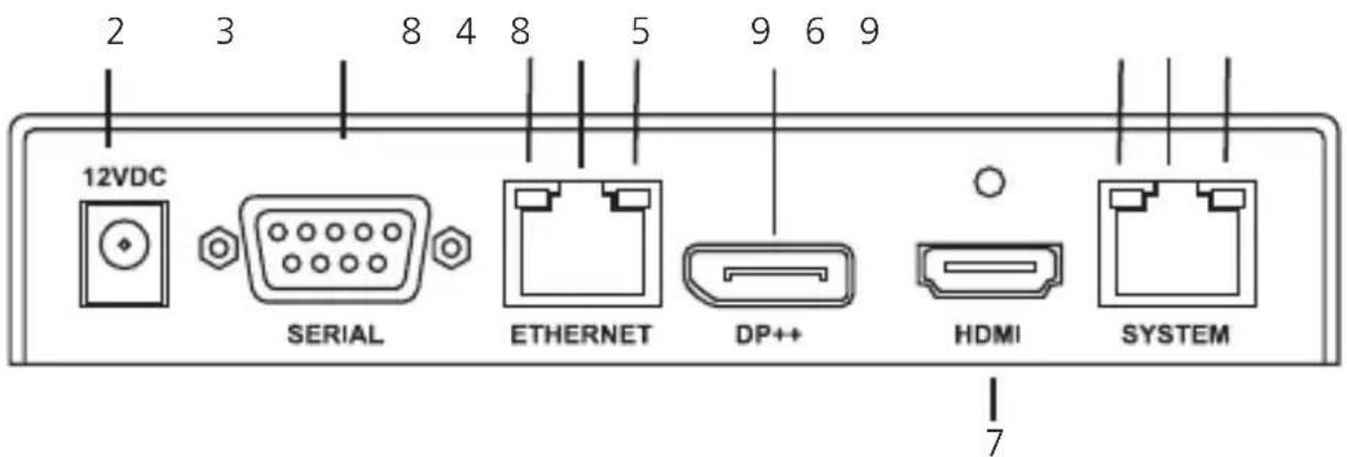
Figure 2-2. HDV-HDMI-TZ back panel.
Table 2-1. Transmitter front- and back-panel components.
| Number Component Description |
| 1 Power LED Lights when power to the unit is on. |
| 2 1.65-mm connector Links to 12-VDC power in. |
| 3 DB9 connector Links to serial port for terminal control. |
| 4 RJ-45 connector Used for IP extension. |
| 5 DisplayPort Connects to DP++ player. |
| 6 RJ-45 connector Links system cable to the receiver. |
| 7 HDMI Connects to HDMI 1.3 player. |
| 8 (2) Ethernet LEDs (1) TX, (1) RX |
| 9 (2) System LEDs (1) TX, (1) RX |
2.4.2 Receiver
Figure 2-3 shows the receiver's back panel. Table 2-2 describes its components.
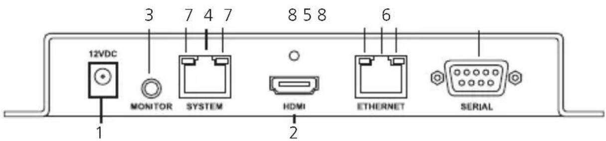
Figure 2-3. HDV-HDMI-RZ back panel.
Table 2-2. Receiver back-panel components.
| Number Component Description |
| 1 1.65-mm connector Links to 12-VDC power in. |
| 2 HDMI connector Used for HDMI 3.1 communication to the display. |
| 3 3.5-mm connector Reserved for future use. |
| 4 RJ-45 connector Links to system cable from the transmitter. |
| 5 RJ-45 conector Used for IP connectivity to the display and/or peripherals. |
| 6 DB9 connector Used for serial control. |
| 7 (2) System LEDs (1) TX, (1) RX |
| 8 (2) Ethernet LEDs (1) TX, (1) RX |
3. Installation
3.1 Compatible Cabling
The HDV-HDMI-TZ and HDV-HDMI-RZ products work with CAT5e/6/7 FTP/UTP network cable.
3.2 Pre-Installation Guidelines
Make sure that the player and the screens are compatible. Check that they work together before connecting the HD View HDMI Transmitter and Receiver.
3.3 Media Distribution
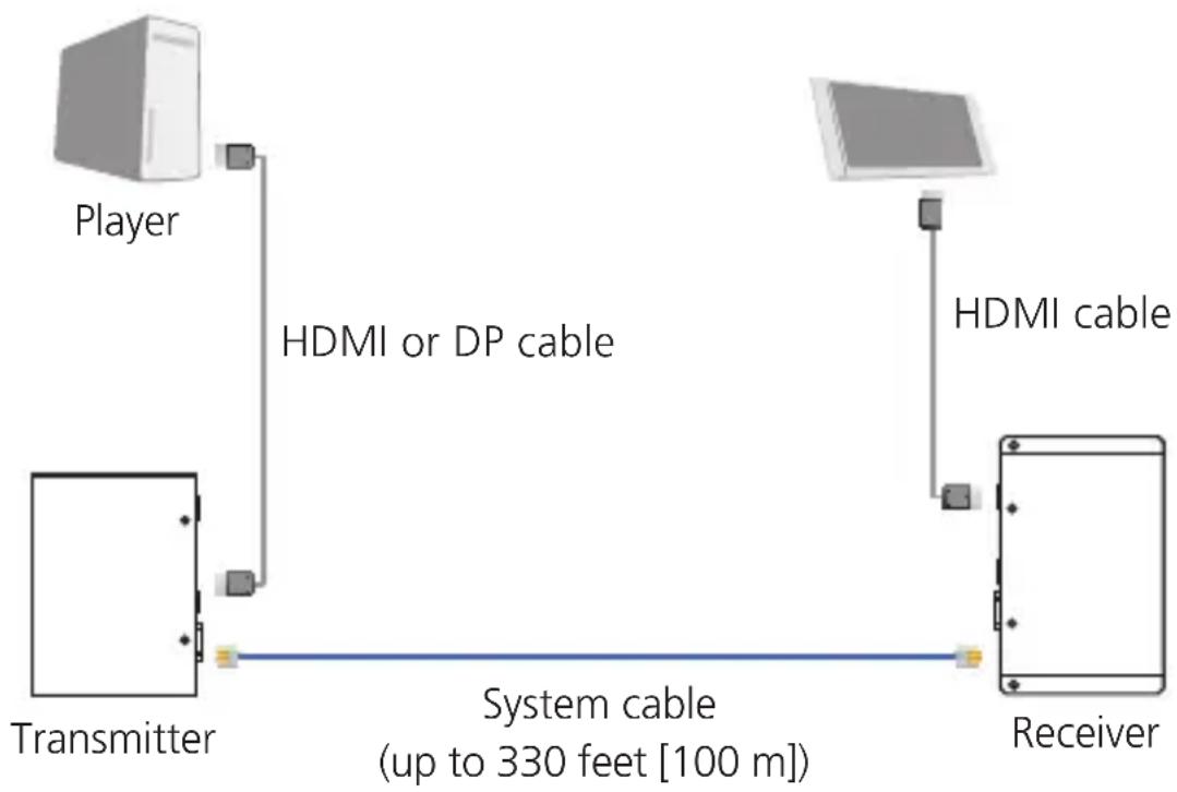
The HD View HDMI Transmitter and Receiver can distribute HD digital media from a single player to a single display located 330 feet (100 m) away. Figure 3-1 illustrates this configuration.
flowchart
graph LR
    A["Transmitter"] -->|HDMI or DP cable| B["Player"]
    B --> C["Receiver"]
    C -->|HDMI cable| D["Receiver"]
    D -->|System cable (up_to_330_feet["100 m"])| A
Figure 3-1. Media distribution to a single display.
Figures 3-2 and 3-3 illustrate all the connections to the HDV-HDMI-TZ series and HDV-HDMI-RZ products. Not all the connections are always needed. This section explains the basic connections. Sections 3.3.1–3.3.4 explain the circumstances that require additional connections.
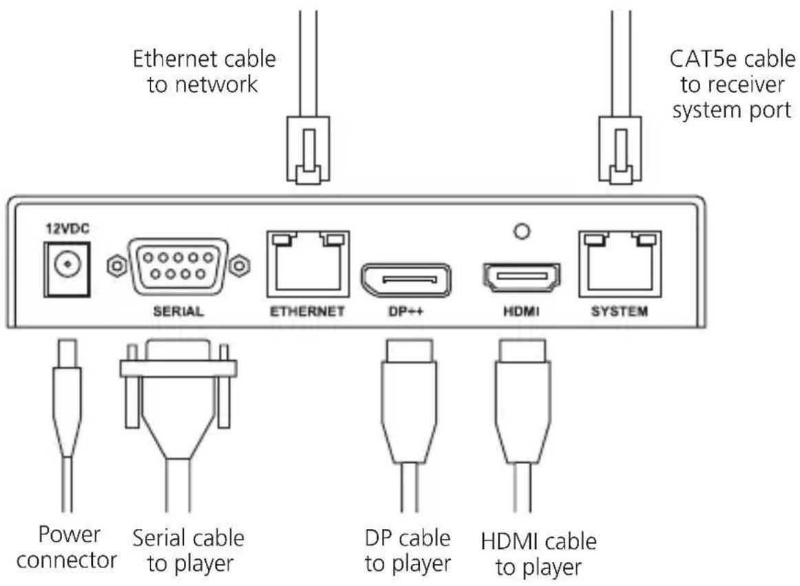
Figure 3-2. Transmitter connections.
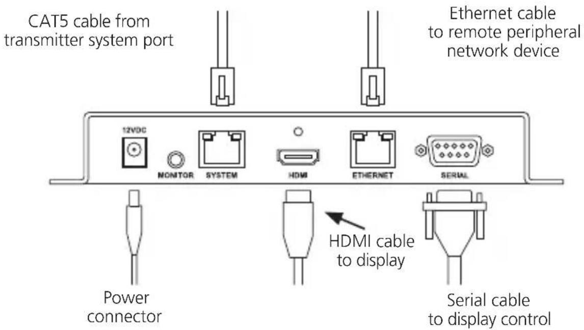
Figure 3-3. Receiver connections.
3.3.1 Connecting the Player and the Screen
Connect the player to the transmitter HDMI port using an HDMI-to-HDMI cable (Type A, male/male) or connect a DP cable to the DP port (DisplayPort male/male). If both are used and active, the HDMI will take priority.
Connect the screen to the receiver HDMI port using an HDMI-to-HDMI cable (Type A, male/male).
3.3.2 Connecting the System Cable
Connect a system cable (up to 330 feet [100 m]) between the system port of the transmitter and the system port of the receiver.
3.3.3 Connecting to the Power Supply
Connect the transmitter and receiver to the power supply with the included 12-V/2-A DC power adapters.
Once connected, the system is ready to transmit the video and audio signals.
3.3.4 Mounting the Receiver
The receiver has VESA standard screw holes, located 10-cm apart, as shown in Figure 3-4. Use two screws (included with the receiver and monitor) to connect the unit to the back of the monitor.
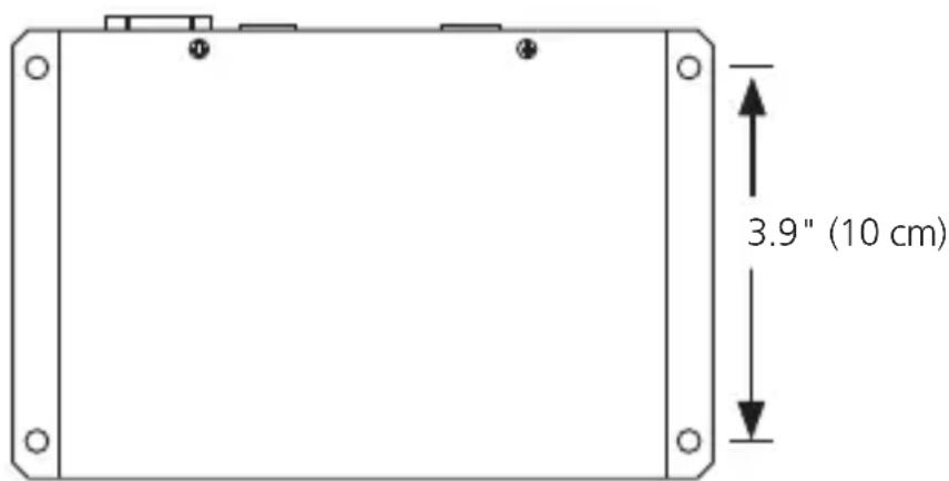
Figure 3-4. Mounting using the VESA screw holes on the receiver.
4. Operation
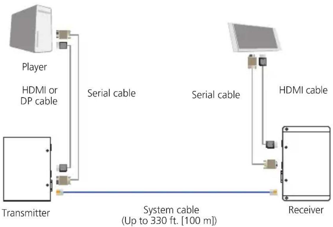
4.1 Serial Control
To enable serial control of remote displays:
- Connect a serial (DB9 male/female) cable between the player and the transmitter.
- Connect a serial (DB9 female/female) cable between the receiver and the screen.
Figure 4-1 illustrates the connections.
flowchart
graph LR
    A["Transmitter"] -->|Serial cable| B["Player"]
    B --> C["Receiver"]
    C -->|Serial cable| D["HDMI cable"]
    D --> E["Receiver"]
    style A fill:#f9f,stroke:#333
    style B fill:#ccf,stroke:#333
    style C fill:#cfc,stroke:#333
    style D fill:#fcc,stroke:#333
Figure 4-1. Serial control.
4.2 Terminal IP Connectivity
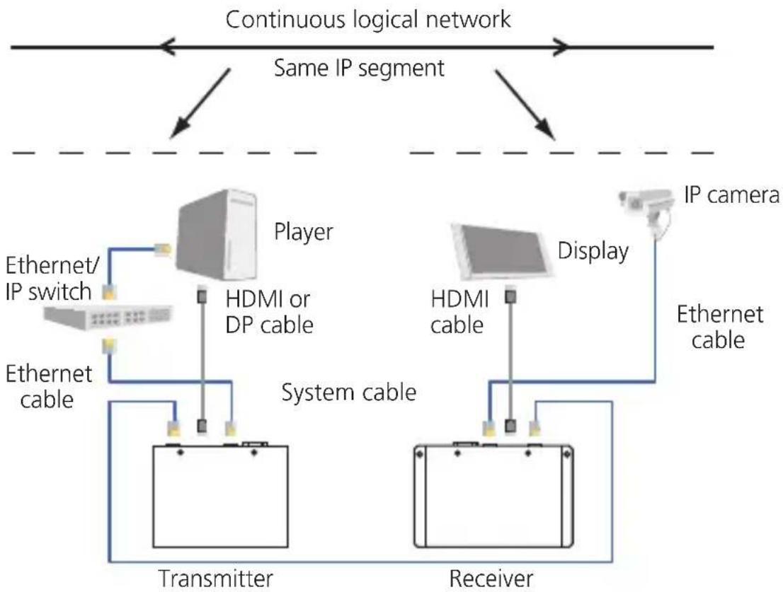
To extend a network from the transmitter side to the remote terminal side:
- Connect a standard Ethernet cable (10-/100BASE-T cable, wired straight-through to conform to T568B standard) between the player side network and the transmitter.
2 Connect a standard Ethernet cable (10-/100BASE-T cable, wired straight-through to conform to T568B standard) between the receiver and the terminal side units.
After you make these connections, you can create an extended IP segment using the extension system.
NOTE: Make sure you have DHCP enabled on your network, because you cannot set/configure the IP addresses in the TX/RX units.
flowchart
graph TD
    A["Continuous logical network"] --> B["Same IP segment"]
    B --> C["Player"]
    B --> D["Display"]
    C --> E["Transmitter"]
    D --> F["Receiver"]
    E --> G["Ethernet/IP switch"]
    E --> H["Ethernet cable"]
    F --> I["HDMI or DP cable"]
    F --> J["System cable"]
    F --> K["IP camera"]
    F --> L["HDMI cable"]
    F --> M["Ethernet cable"]
Figure 4-2. Terminal IP connectivity.
4.3 Scalability
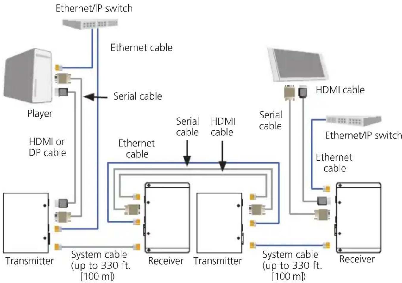
Cascade a receiver with a transmitter to increase the system distance.
Cascading to Increase the Distance
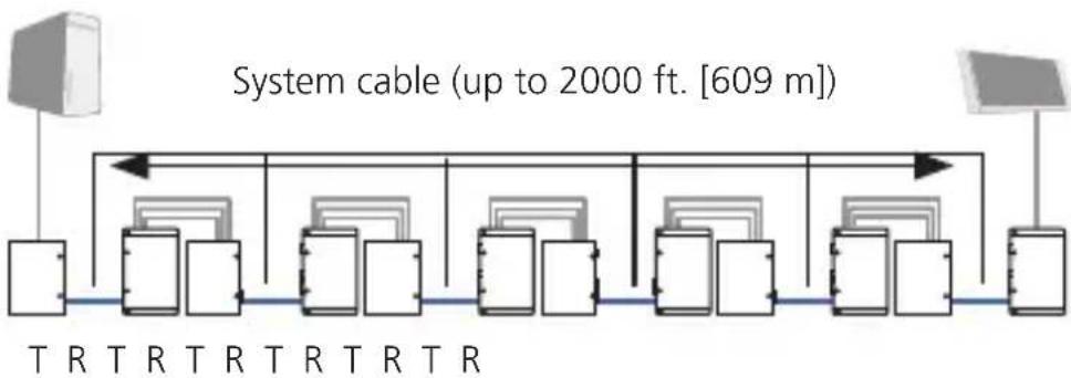
Cascade up to six distribution systems to increase the distance up to 2000 feet (600 m). Figure 4-3 illustrates a two-hop cascaded system.
flowchart
graph TD
    A["Transmitter"] -->|Serial cable| B["Receiver"]
    C["Player"] -->|Serial cable| B
    D["Transmission"] -->|Serial cable| B
    E["Transmitter"] -->|Serial cable| F["Receiver"]
    G["Player"] -->|Serial cable| H["Transmission"]
    I["Transmission"] -->|Serial cable| J["Receiver"]
    K["Ethernet/IP switch"] --> L["Player"]
    M["HDMI or DP cable"] --> N["Player"]
    O["Hardware"] --> P["HDMI cable"]
    Q["Hardware"] --> R["HDMI cable"]
    S["Hardware"] --> T["Hardware"]
    U["Hardware"] --> V["Hardware"]
    W["Hardware"] --> X["Hardware"]
    Y["Hardware"] --> Z["Hardware"]
    AA["Hardware"] --> AB["Hardware"]
    AC["Hardware"] --> AD["Hardware"]
    AE["Hardware"] --> AF["Hardware"]
    AG["Hardware"] --> AH["Hardware"]
    AI["Hardware"] --> AJ["Hardware"]
    AK["Hardware"] --> AL["Hardware"]
    AM["Hardware"] --> AN["Hardware"]
    AO["Hardware"] --> AP["Hardware"]
    AQ["Hardware"] --> AR["Hardware"]
    AS["Hardware"] --> AT["Hardware"]
    AU["Hardware"] --> AV["Hardware"]
    AW["Hardware"] --> AX["Hardware"]
    AY["Ethernet cable"] --> AZ["Serial cable"]
    BA["Ethernet cable"] --> BB["Serial cable"]
    BC["Ethernet cable"] --> BD["Serial cable"]
    BE["Ethernet cable"] --> BF["Serial cable"]
    BG["Ethernet cable"] --> BH["Serial cable"]
    BI["Ethernet cable"] --> BJ["Serial cable"]
    BK["Ethernet cable"] --> BL["Serial cable"]
    BM["HDMI cable"] --> BN["HDMI cable"]
    BO["HDMI cable"] --> BP["HDMI cable"]
    BP["HDMI cable"] --> BQ["HDMI cable"]
    BR["HDMI cable"] --> BS["HDMI cable"]
    BT["HDMI cable"] --> BU["HDMI cable"]
    BV["HDMI cable"] --> BW["HDMI cable"]
    BX["HDMI cable"] --> BY["HDMI cable"]
    BZ["HDMI cable"] --> CA["HDMI cable"]
    CB["HDMI cable"] --> CC["HDMI cable"]
    CD["HDMI cable"] --> DE["HDMI cable"]
    DF["HDMI cable"] --> DG["HDMI cable"]
    DH["HDMI cable"] --> DI["HDMI cable"]
    DJ["HDMI cable"] --> DK["HDMI cable"]
    DL["HDMI cable"] --> DM["HDMI cable"]
    DN["HDMI cable"] --> DO
    DG["HDMI cable"] --> DB["HDMI cable"]
Figure 4-3. Hop cascaded system.
To connect the receiver to the transmitter, connect the following cables as shown in Figure 4-3:
• HDMI to HDMI (Type A, male/male).
- For serial control: Serial cable (DB9 male/female). See Section 4.1.
- For IP connectivity: Ethernet 10-/100BASE-T straight-through cable (T568B). See Section 4.2.
Figure 4-4 illustrates a hop cascaded system up to 2000 feet (600 m).
Player
flowchart
graph LR
    A["Central Cable"] --> B["1000m Cable"]
    B --> C["1000m Transmission"]
    C --> D["1000m Transmission"]
    D --> E["1000m Transmission"]
    E --> F["1000m Transmission"]
    F --> G["1000m Transmission"]
    G --> H["1000m Transmission"]
    H --> I["1000m Transmission"]
    I --> J["1000m Transmission"]
    J --> K["1000m Transmission"]
    K --> L["1000m Transmission"]
    L --> M["1000m Transmission"]
    M --> N["1000m Transmission"]
    N --> O["1000m Transmission"]
    O --> P["1000m Transmission"]
    P --> Q["1000m Transmission"]
    Q --> R["1000m Transmission"]
    R --> S["1000m Transmission"]
    S --> T["1000m Transmission"]
    T --> U["1000m Transmission"]
    U --> V["1000m Transmission"]
    V --> W["1000m Transmission"]
    W --> X["1000m Transmission"]
    X --> Y["1000m Transmission"]
    Y --> Z["1000m Transmission"]
    Z --> AA["1000m Transmission"]
    AA --> AB["1000m Transmission"]
    AB --> AC["1000m Transmission"]
    AC --> AD["1000m Transmission"]
    AD --> AE["1000m Transmission"]
    AE --> AF["1000m Transmission"]
    AF --> AG["1000m Transmission"]
    AG --> AH["1000m Transmission"]
    AH --> AI["1000m Transmission"]
    AI --> AJ["1000m Transmission"]
    AJ --> AK["1000m Transmission"]
    AK --> AL["1000m Transmission"]
    AL --> AM["1000m Transmission"]
    AM --> AN["1000m Transmission"]
    AN --> AO["1000m Transmission"]
    AO --> AP["1000m Transmission"]
    AP --> AQ["1000m Transmission"]
    AQ --> AR["1000m Transmission"]
    AR --> AS["1000m Transmission"]
    AS --> AT["1000m Transmission"]
    AT --> AU["1000m Transmission"]
    AU --> AV["1000m Transmission"]
    AV --> AW["1000m Transmission"]
    AW --> AX["1000m Transmission"]
T = Transmitter
R = Receiver
Figure 4-4. Six-hop cascaded system.
Black Box Tech Support: FREE! Live. 24/7.
Tech support the way it should be.

natural_image
Black-and-white portrait of a smiling woman wearing a headset (no visible text or symbols)Great tech support is just 30 seconds away at 724-746-5500 or blackbox.com.

BLACK BOX
NETWORK SERVICES
About Black Box
Black Box Network Services is your source for an extensive range of networking and infrastructure products. You'll find everything from cabinets and racks and power and surge protection products to media converters and Ethernet switches all supported by free, live 24/7 Tech Support available in 30 seconds or less.
© Copyright 2011. Black Box Corporation. All rights reserved.
HDV-HDMI-TZ version 1


- HD View HDMI Transmitter and Receiver
- Extend real-time, full-HD digital media over ordinary CATx cable—and communicate via IP with remote Ethernet peripherals.
- FEDERAL COMMUNICATIONS COMMISSION AND INDUSTRY CANADA RADIO FREQUENCY INTERFERENCE STATEMENTS
- Trademarks Used in this Manual
- Contents
- ChapterPage
- Specifications
- Overview
- Introduction
- Features
- What's Included
- HDV-HDMI-TZ-K:
- HDV-HDMI-RZ-K:
- HDV-HDMI-TZ:
- HDV-HDMI-RZ:
- HDV-HDMI-TZ-A-K:
- HDV-HDMI-RZ-A-K:
- Hardware Description
- Transmitter
- Receiver
- Installation
- Compatible Cabling
- Pre-Installation Guidelines
- Media Distribution
- Connecting the Player and the Screen
- Connecting the System Cable
- Connecting to the Power Supply
- Mounting the Receiver
- Operation
- Serial Control
- Terminal IP Connectivity
- Scalability
- Cascading to Increase the Distance
- BLACK BOX
- NETWORK SERVICES
- About Black Box
Brand : Black Box
Model : HDV-HDMI-RZ
Category : Audio/video extender