
MCX S9 - Audio/video extender Black Box - Free user manual and instructions
Find the device manual for free MCX S9 Black Box in PDF.


| Product Type | Audio/Video Extender (Encoder and Decoder) |
| Model Series | MCX-S9 (includes MCX-S9-ENC, MCX-S9-DEC, MCX-S9C-ENC, MCX-S9C-DEC) |
| Video Input (Encoder) | 1x HDMI 2.0, 1x DisplayPort 1.2a |
| Video Output (Decoder) | 1x HDMI 2.0 |
| Max Resolution | 4096x2160 @ 60 Hz, 3840x2160 @ 60 Hz (4:4:4), 3840x2160 @ 60 Hz (4:2:0 10-bit HDR) |
| Audio Input (Encoder) | 1x HDMI, 1x DisplayPort, 1x 3.5mm jack (stereo unbalanced) |
| Audio Output (Decoder) | 1x HDMI 2.0, 1x 3.5mm jack (stereo unbalanced) |
| Network Interface | 1x RJ-45 10GBASE-T, 1x SFP+ (fiber) on MCX-S9-ENC/DEC, 1x RJ-45 10GBASE-T on MCX-S9C-ENC/DEC |
| Control Ports | 1x RJ-45 10/100/1000BASE-T (LAN), 1x RS-232 (3.5mm Phoenix), 1x IR input, 1x IR output |
| USB Ports | Encoder: 1x USB Type B; Decoder: 2x USB Type A; MCX-S9C models: none |
| Transmission Distance | Up to 328 ft (100 m) over CAT6a/CAT7 copper; fiber distance depends on SFP+ |
| Latency | Zero-frame |
| HDCP Support | HDCP 2.2 compliant |
| Power Supply | 12 VDC, 3 A (power adapter included) |
| Dimensions (MCX-S9-ENC/DEC with brackets) | 1.8" H x 10.4" W x 5.5" D (4.5 x 23 x 13.9 cm) |
| Dimensions (MCX-S9C-ENC/DEC) | 1.38" H x 8.27" W x 5.47" D (3.51 x 21.01 x 13.89 cm) |
| Weight | 3.31 lb (1.50 kg) |
| Operating Temperature | 32 to 104°F (0 to 40°C) |
| Storage Temperature | -4 to 158°F (-20 to 70°C) |
| Humidity | 10 to 90%, noncondensing |
| ESD Protection | ±8 kV air gap, ±4 kV contact (Human Body Model) |
| Included Accessories | Power adapter (US/UK/EU/AU cord), 3.5mm Phoenix male connector, mounting ears (2), IR emitter (for encoder) or IR receiver (for decoder) |
| Maintenance | Clean with dry cloth; do not obstruct ventilation; unplug during storms |
| Safety Compliance | FCC Class B, CE, RoHS2, NOM |
Frequently Asked Questions - MCX S9 Black Box
User questions about MCX S9 Black Box
0 question about this device. Answer the ones you know or ask your own.
Ask a new question about this device
Download the instructions for your Audio/video extender in PDF format for free! Find your manual MCX S9 - Black Box and take your electronic device back in hand. On this page are published all the documents necessary for the use of your device. MCX S9 by Black Box.
USER MANUAL MCX S9 Black Box
natural_image
Exterior view of a black and white industrial device labeled 'MCX S9' with ports and indicators (no readable text beyond branding)TABLE OF CONTENTS
IMPORTANT SAFETY INSTRUCTIONS .... 4
QUICK INSTALLATION GUIDE....5
Preparation 5
Connecting One TX to One RX Directly....5
Connecting TX to RX....5
Configuring TX and RX 5
Connecting the TX and RX to a Switch 5
1. SPECIFICATIONS....6
2. OVERVIEW....14
2.1 About this Manual 14
2.2 Introduction 14
2.3 Port Differences....14
2.4 Features 14
2.5 What's Included 15
2.6 Hardware Description....16
2.6.1 MCX-S9-ENC or MCX-S9D-ENC Unit 16
2.6.2 MCX-S9-DEC Unit 18
2.6.3 MCX-S9C-ENC Unit 20
2.6.4 MCX-S9C-DEC Unit 22
3. TYPICAL APPLICATIONS ...... 24
3.1 Point-to-Point....24
3.2 Point-to-Multipoint 25
3.3 Multipoint-to-Point 26
3.4 Multipoint-to-Multipoint 26
4. HARDWARE INSTALLATION....27
TABLE OF CONTENTS
NEED HELP?
LEAVE THE TECH TO US
LIVE 24/7
TECHNICAL
SUPPORT
1.87 7.877.2269
APPENDIX A. REGULATORY INFORMATION 28
A.1 FCC Class B Statement 28
A.2 CE and RoHS2....28
A.3 NOM Statement 29
APPENDIX B.DISCLAIMER/TRADEMARKS 30
B.1 Disclaimer 30
B.2 Trademarks Used in this Manual....30
IMPORTANT SAFETY INSTRUCTIONS
NEED HELP?
LEAVE THE TECH TO US
LIVE 24/7
TECHNICAL
SUPPORT
1.87 7.877.2269
- Do not expose this apparatus to rain, moisture, dripping or splashing and do not place objects filled with liquids, such as vases, on the apparatus.
- Clean this apparatus only with a dry cloth.
- Do not install or place this unit in a bookcase, built-in cabinet or in another confined space. Ensure that the unit is well ventilated.
- To prevent the risk of electric shock or a fire hazard caused by overheating, do not obstruct the unit's ventilation openings with newspapers, tablecloths, curtains and similar items.
- Do not install near any heat sources, such as radiators, heat registers, stoves or other apparatus (including amplifiers) that produce heat.
- Do not place sources of naked flames, such as lighted candles, on the unit.
- Unplug this apparatus during lightning storms or when unused for long periods of time.
- Protect the power cord from being walked on or pinched, particularly at plugs.
- Only use attachments/accessories specified by the manufacturer.
- Refer all servicing to qualified service personnel.
QUICK INSTALLATION GUIDE
PREPARATION
Before you start installing MCX-S9 products, carefully read and strictly follow the instructions below.
- Only use accessories and cables that are supplied with Black Box products or purchased as required
- Correctly connect all the cables
Use the correct power supplies and connect them to Black Box devices in accordance with the specification for electric construction
CONNECTING ONE TX TO ONE RX DIRECTLY
CONNECTING TX TO RX
- Connect a video source to the encoder and a display device to the decoder.
- Connect the MCX-S9-DEC to the MCX-S9-ENC with a network cable that meets the 10GbE specification. Be careful to plug the network cable's RJ-45 connectors into these devices' 10GbE ports.
- Connect all the devices to their power supplies. After a while, the display will show the content of the video source.
CONFIGURING TX AND RX
- Connect your PC to the receiver with a network cable. Plug the network cable's one end into the decoder's LAN port and the other end into your PC's Ethernet port.
- Configure your PC's network settings with IP address 169.254.1.11 and subnet mask 255.255.0.0, leaving gateway and DNS blank.
- Launch the matching Manager software, then maximize its window to view more contents. The software will automatically discover the two devices: the transmitter would be shown in the Encoders section and the receiver would be shown in the Decoders section.
- Adjust the configurations of the two devices if necessary.
CONNECTING THE TX AND RX TO A SWITCH
- Connect all MCX-S9-ENC and MCX-S9-DEC units to a 10GbE switch with network cables that meet the 10GbE specification. Be careful to plug the network cable's RJ-45 or fiber connectors into the devices' 10GbE ports.
- Connect your PC to the switch, making sure that all devices' LAN ports aren't plugged into any network cables.
- Configure your PC's network settings with IP address 169.254.1.11 and subnet mask 255.255.0.0, leaving gateway and DNS blank.
- Start the Manager software and maximize its window and the software will discover all devices automatically. The transmitters will be shown in the Encoders section and the receivers will be shown in the Decoders section.
- Adjust the configurations and control all devices with the Manager.
CHAPTER 1: SPECIFICATIONS
TABLE 1-1. SPECIFICATIONS, MCX-S9-ENC SERIES UNITS
| SPECIFICATION DESCRIPTION | |
| Video | |
| Input Connectors (1) HDMI 2.0, (1) DisplayPort 1.2a | |
| Input Video Resolutions | 640 x 480 ^8 , 800 x 600 ^8 , 1024 x 768 ^3 , 1280 x 1024 ^5 , 1360 x 768 ^8 , 1440 x 900 ^8 , 1440 x 1050 ^8 , 1600 x 1200 ^8 ,720 x 480 ^7 (480i59), 720 x 480 ^7 (480p59), 720 x 576 ^5 (576i50), 720 x 576 ^5 (576p50), 1280 x 720 ^5 (720p50),1280 x 720 ^7 (720p59), 1280 x 720 ^8 (720p60), =1920 x 1080 ^6 (1080i50), 1920 x 1080 ^7 (1080i59), 1920 x 1080 ^8 (1080i60),1920 x 1080 ^1 (1080p23), 1920 x 1080 ^2 (1080p24),1920 x 1080 (1080p25), 1920 x 1080 (1080p29), 1920 x 1080 ^5 (1080p30), 1920 x 1080 ^6 (1080p50), 1920 x 1080 ^7 (1080p59), 1920 x 1080 ^8 (1080p60), 3840 x 2160 ^1 (2160p23),3840 x 2160 ^2 (2160p24), 3840 x 2160 ^4 (2160p25), 3840 x 2160 ^2 (2160p29), 3840 x 2160 ^5 (2160p30), 3840 x 2160 ^5 (2160p60), 4096 x 2160 ^5 , 4096 x 2160 ^8 1 = at 23.98 Hz, 2 = at 24 Hz, 3 = at 25 Hz, 4 = at 29.97 Hz, 5 = at 30 Hz, 6 = at 50 Hz, 7 = at 59.94 Hz, 8 = at 60 Hz,9 = at 75 Hz |
| Output Connectors (1) RJ-45 10GBASE-T, (1) SFP+ | |
| Output Video Resolutions | 640 x 480 ^8 , 800 x 600 ^8 , 1024 x 768 ^3 , 1280 x 1024 ^5 , 1360 x 768 ^8 , 1440 x 900 ^8 , 1440 x 1050 ^8 , 1600 x 1200 ^8 ,720 x 480 ^7 (480i59), 720 x 480 ^7 (480p59), 720 x 576 ^5 (576i50), 720 x 576\( ^5 (576p50), 1280 x 720\( ^5 (720p50),1280 x 720 ^7 (720p59), 1280 x 720 ^8 (720p60), =1920 x 1080 ^6 (1080i59), 1920 x 1080 ^7 (1080i59), 1920 x 1080 ^8 (1080i60),1920 x 1080 ^1 (1080p23), 1920 x 1080 ^2 ((1080p24),1920 x 1080 (1080p25), 1920 x 1080 (1080p29), 1920 x 1080 ^5 (1080p30), 1920 x 1080 ^6 (1080p50). 1920 x 1080 ^7 (1080p59), 1920 x 1080 ^8 (1080p60), 3840 x 2160 ^1 (2160p23),3840 x 2160 ^2 (1080p24), 3840 x 2160 ^4 (2160p25), 3840 x 2160 ^2 (2160p29), 3840 x 2160 ^5 (2160p30), 3840 x 2160 ^5 (2160p60), 4096 x 2160 ^5 , 4096 x 2160 ^8 1 = at 23.98 Hz, 2 = at 24 Hz, 3 = at 25 Hz, 4 = at 29.97 Hz, 5 = at 30 Hz, 6 = 50 Hz, 7 = at 59.94 Hz, 8 = at 60 Hz,9 = at 75 Hz |
| Audio | |
| Input Connectors (1) HDMI, (1) DisplayPort 1.2a, (1) 3.5-mm jack | |
| Supported Input | HDMI/DP:LPCM, 2.0/5.1/7.1 channel, 44.1/48/96/192 kHzDolby True HD, up to 7.1, 192 kHzDTS-HD Master, up to 7.1, 192 kHzDolby Digital AC-3 (DVD format)DTS version 1 (DVD format);3.5 mm jack:Unbalanced stereo audio |
| Output Connectors None | |
| Supported Output None | |
| USB | |
| Connectors (1) USB Type B | |
| Control | |
| IR Input | (1) 3.5 mm jack connector, connects to an IR receiver for IR communication with an IR transmitter connecting to another device |
| IR Output | (1) 3.5 mm jack connector, connects to an IR transmitter for IR communication with an IR receiver connecting to another device |
| Control Connectors | (1) 3.5-mm 4-pin Phoenix connector for RS-232 communication; (1) RJ-45 10/100/1000BASE-T Ethernet port |
| Control Method | Ethernet:PC software: for configuring, controlling and upgradingWeb browser: for controllingAPI set: for integrating with the 3rd party control systemRS-232:PC software: for testing and upgrading the device itselfCommon RS-232 device: for bi-directional communication with an RS-232 device connected to another device |
CHAPTER 1: SPECIFICATIONS
NEED HELP?
LEAVE THE TECH TO US
LIVE 24/7
TECHNICAL
SUPPORT
1.87 7.877.2269
TABLE 1-1 (CONTINUED). SPECIFICATIONS, MCX-S9-ENC SERIES UNITS
| SPECIFICATION DESCRIPTION | |
| General | |
| Operating Temperature 32 to 104°F (0 to 40°C) | |
| Storage Temperature -4 to +158 F (-20 to +70°C) | |
| Humidity 10 to 90%, noncondensing | |
| Product Weight 3.31 lb. (1.50 kg) | |
| Power Supply 12 VDC | |
| Transport Distance | Twisted Pair:98.4 ft. (30 m) with CAT6 cable,328 ft. (100 m) with CAT6a or CAT7 cable;Fiber:Depends on SFP+ installed |
| Dimensions | Including brackets: 1.8" H x 10.4" W x 5.5" D (4.5 x 23 x 13.9 cm)Without brackets: 1.4" H x 9.1" W x 5.5" D (3.5 x 23 x 13.9 cm) |
| ESD Protection | Human-body Model: ±8 kV (Air-gap discharge)/±4 kV (Contact discharge) |
TABLE 1-2. SPECIFICATIONS, MCX-S9-DEC SERIES UNITS
| SPECIFICATION DESCRIPTION | |
| Video | |
| Input Connectors (1) RJ-45 10GBASE-T, (1) SFP+ | |
| Input Video Resolutions | 640 x 480 ^8 , 800 x 600 ^8 , 1024 x 768 ^3 , 1280 x 1024 ^5 , 1360 x 768 ^8 , 1440 x 900 ^8 , 1440 x 1050 ^8 , 1600 x 1200 ^8 ,720 x 480 ^7 (480i59), 720 x 480 ^7 (480p59), 720 x 576 ^5 (576i50), 720 x 576 ^5 (576p50), 1280 x 720 ^3 (720p50),1280 x 720 ^7 (720p59), 1280 x 720 ^8 (720p60), =1920 x 1080 ^6 (1080i50), 1920 x 1080 ^7 (1080i59), 1920 x 1080 ^8 (1080i60),1920 x 1080 ^1 (1080p23), 1920 x 1080 ^2 (1080p24),1920 x 1080 (1080p25), 1920 x 1080 (1080p29), 1920 x 1080 ^5 (1080p30), 1920 x 1080 ^6 (1080p50), 1920 x 1080 ^7 (1080p59), 1920 x 1080 ^8 (1080p60), 3840 x 2160 ^1 (2160p23),3840 x 2160 ^2 (2160p24), 3840 x 2160 ^4 (2160p25), 3840 x 2160 ^2 (2160p29), 3840 x 2160 ^5 (2160p30), 3840 x 2160 ^3 (2160p60), 4096 x 2160 ^5 , 4096 x 2160 ^8 1 = at 23.98 Hz, 2 = at 24 Hz, 3 = at 25 Hz, 4 = at 29.97 Hz, 5 = at 30 Hz, 6 = at 50 Hz, 7 = at 59.94 Hz, 8 = at 60 Hz,9 = at 75 Hz |
| Output Connectors (1) HDMI 2.0 | |
| Output Video Resolutions | 640 x 480 ^8 , 800 x 600 ^8 , 1024 x 768 ^3 , 1280 x 1024 ^5 , 1360 x 768 ^8 , 1440 x 900 ^8 , 1440 x 1050 ^8 , 1600 x 1200 ^8 ,720 x 480 ^7 (480i59), 720 x 480 ^7 (480p59), 720 x 576 ^5 (576i50), 720 x 576\( ^5 (576p50), 1280 x 720\( ^3 (720p50),1280 x 720 ^7 (720p59), 1280 x 720 ^8 (720p60), =1920 x 1080 ^6 (1080i59), 1920 x 1080 ^7 (1080i59), 1920 x 1080 ^8 (1080i60),1920 x 1080 ^1 (1080p23), 1920 x 1080 ^2 ((1080p24),1920 x 1080 (1080p25), 1920 x 1080 (1080p29), 1920 x 1080 ^5 (1080p30), 1920 x 1080 ^6 (1080p50). 1920 x 1080 ^7 (1080p59), 1920 x 1080 ^8 (1080p60), 3840 x 2160 ^1 (2160p23),3840 x 2160 ^2 (1080p24), 3840 x 2160 ^4 (2160p25), 3840 x 2160 ^2 (2160p29), 3840 x 2160 ^5 (2160p30), 3840 x 2160 ^5 (2160p60), 4096 x 2160 ^5 , 4096 x 2160 ^8 1 = at 23.98 Hz, 2 = at 24 Hz, 3 = at 25 Hz, 4 = at 29.97 Hz, 5 = at 30 Hz, 6 =at 50 Hz, 7 = at 59.94 Hz, 8 = at 60 Hz,9 = at 75 Hz |
| Audio | |
| Input Connectors None | |
| Supported Input None | |
| Output Connectors (1) HDMI 2.0, (1) 3.5-mm jack | |
| Supported Output | HDMI:LPCM, 2.0/5.1/7.1 channel, 44.1/48/96/192 kHzDolby True HD, up to 7.1, 192 kHzDTS-HD Master, up to 7.1, 192 kHzDolby Digital AC-3 (DVD format)DTS version 1 (DVD format);3.5 mm jack:Unbalanced stereo audio |
| USB | |
| Connectors (2) USB Type A | |
| Control | |
| IR Input | (1) 3.5 mm jack connector, connects to an IR receiver for IR communication with an IR transmitter connecting to another device |
| IR Output | (1) 3.5 mm jack connector, connects to an IR transmitter for IR communication with an IR receiver connecting to another device |
| Control Connectors | (1) 3.5-mm 4-pin Phoenix connector for RS-232 communication; (1) RJ-45 10/100/1000BASE-T Ethernet port |
| Control Method | Ethernet:PC software: for configuring, controlling and upgradingWeb browser: for controllingAPI set: for integrating with the 3rd party control systemRS-232:PC software: for testing and upgrading the device itselfCommon RS-232 device: for bi-directional communication with an RS-232 device connected to another device |
CHAPTER 1: SPECIFICATIONS
NEED HELP?
LEAVE THE TECH TO US
LIVE 24/7
TECHNICAL
SUPPORT
1.87 7.877.2269
TABLE 1-2 (CONTINUED). SPECIFICATIONS, MCX-S9-DEC SERIES UNITS
| SPECIFICATION DESCRIPTION | |
| General | |
| Operating Temperature 32 to 104°F (0 to 40°C) | |
| Storage Temperature -4 to +158 F (-20 to +70°C) | |
| Humidity 10 to 90%, noncondensing | |
| Product Weight 3.31 lb. (1.50 kg) | |
| Power Supply 12 VDC | |
| Transport Distance | Twisted Pair:98.4 ft. (30 m) with CAT6 cable,328 ft. (100 m) with CAT6a or CAT7 cable;Fiber:Depends on SFP+ installed |
| Dimensions | Including brackets: 1.8" H x 10.4" W x 5.5" D (4.5 x 23 x 13.9 cm)Without brackets: 1.4" H x 9.1" W x 5.5" D (3.5 x 23 x 13.9 cm) |
| ESD Protection Human-body Model: ±8 kV (Air-gap discharge)/±4 kV (Contact discharge) | |
TABLE 1-3. SPECIFICATIONS, MCX-S9C-ENC SERIES UNITS
| SPECIFICATION DESCRIPTION | |
| Video | |
| Input Connectors (1) HDMI 2.0, (1) DisplayPort 1.2a | |
| Input Video Resolutions | 640 x 4805, 800 x 6005, 1024 x 7686, 1280 x 10245, 1360 x 7688, 1440 x 9005, 1440 x 10508, 1600 x 12008, 720 x 4807(480i59), 720 x 4807(480p59), 720 x 5765(576i50), 720 x 5765(576p50), 1280 x 7205(720p50), 1280 x 7207(720p59), 1280 x 7205(720p60), =1920 x 10806(1080i50), 1920 x 10807(1080i59), 1920 x 10808(1080i60), 1920 x 10801(1080p23), 1920 x 10802(1080p24), 1920 x 1080(1080p25), 1920 x 1080(1080p29), 1920 x 10805(1080p30), 1920 x 10806(1080p50), 1920 x 10807(1080p59), 1920 x 10808(1080p60), 3840 x 21601(2160p23), 3840 x 21602(2160p24), 3840 x 21604(2160p25), 3840 x 21604(2160p29), 3840 x 21605(2160p30), 3840 x 21605(2160p60), 4096 x 21605, 4096 x 216081 = at 23.98 Hz, 2 = at 24 Hz, 3 = at 25 Hz, 4 = at 29.97 Hz, 5 = at 30 Hz, 6 = at 50 Hz, 7 = at 59.94 Hz, 8 = at 60 Hz, 9 = at 75 Hz |
| Output Connectors (1) RJ-45 10GBASE-T | |
| Output Video Resolutions | 640 x 4805, 800 x 6005, 1024 x 7686, 1280 x 10245, 1360 x 7688, 1440 x 9005, 1440 x 10508, 1600 x 12008. 720 x 4807(480i59), 720 x 4807(480p59), 720 x 5765(576i50), 720 x 5765(576p50), 1280 x 7205(720p50), 1280 x 7107(720p59), 1280 x 7205(720p60), =1920 x 10806(1080i50), 1920 x 10807(1080i59), 1920 x 10808(1080i60), 1920 x 21601(1080p23), 1920 x 10807(1080p24), 1920 x 1080(1080p25), 1920 x 1080(1080p29), 1920 x 10805(1080p30), 1920 x 10806(1080p50), 1920 x 11087(1080p59), 1920 x 10808(1080p60), 3840 x 21601(2160p23), 3840 x 21602(2160p24), 3840 x 21604(2160p25), 3840x 21604(2160p29), 3840 x 21605(2160p30), 3840 x 21605(2160p60), 4096 x 21605, 4096 x 216081 = at 23.98 Hz, 2 = at 25 Hz, 4 = at 29.97 Hz, 5 = at 30 Hz, 6 = at 50 Hz, 7 = at 59.94 Hz, 8 = at 60 Hz, 9 = at 75 Hz |
| Audio | |
| Input Connectors (1) HDMI, (1) 3.5-mm jack | |
| Supported Input | HDMI/DP:LPCM, 2.0/5.1/7.1 channel, 44.1/48/96/192 kHzDolby True HD, up to 7.1, 192 kHzDTS-HD Master, up to 7.1, 192 kHzDolby Digital AC-3 (DVD format)DTS version 1 (DVD format);3.5 mm jack:Unbalanced stereo audio |
| Output Connectors None | |
| Supported Output None | |
| Control | |
| IR Input | (1) 3.5 mm jack connector, connects to an IR receiver for IR communication with an IR transmitter connecting to another device |
| IR Output | (1) 3.5 mm jack connector, connects to an IR transmitter for IR communication with an IR receiver connecting to another device |
| Control Connectors | (1) 3.5-mm 4-pin Phoenix connector for RS-232 communication; (1) RJ-45 10/100/1000BASE-T Ethernet port |
| Control Method | Ethernet:PC software: for configuring, controlling and upgradingWeb browser: for controllingAPI set: for integrating with the 3rd party control systemRS-232:PC software: for testing and upgrading the device itselfCommon RS-232 device: for bi-directional communication with an RS-232 device connected to another device |
CHAPTER 1: SPECIFICATIONS
NEED HELP?
LEAVE THE TECH TO US
LIVE 24/7
TECHNICAL
SUPPORT
1.87 7.877.2269
TABLE 1-3 (CONTINUED). SPECIFICATIONS, MCX-S9C-ENC SERIES UNITS
| SPECIFICATION DESCRIPTION | |
| General | |
| Operating Temperature 32 to 104°F (0 to 40°C) | |
| Storage Temperature -4 to +158 F (-20 to +70°C) | |
| Humidity 10 to 90%, noncondensing | |
| Product Weight 3.31 lb. (1.50 kg) | |
| Power Supply 12 VDC | |
| Transport Distance | Twisted Pair:98.4 ft. (30 m) with CAT6 cable,328 ft. (100 m) with CAT6a or CAT7 cable |
| Dimensions 1.38" H x 8.27" W x 5.47" D (3.51 x 21.01 x 13.89 cm) | |
| ESD Protection | Human-body Model: ±8 kV (Air-gap discharge)/±4 kV (Contact discharge) |
CHAPTER 1: SPECIFICATIONS
TABLE 1-4. SPECIFICATIONS, MCX-S9C-DEC SERIES UNITS
| SPECIFICATION DESCRIPTION | |
| Video | |
| Input Connectors (1) RJ-45 10GBASE-T | |
| Input Video Resolutions | 640 x 480 ^8 , 800 x 600 ^5 , 1024 x 768 ^3 , 1280 x 1024 ^5 , 1360 x 768 ^6 , 1440 x 900 ^8 , 1440 x 1050 ^8 , 1600 x 1200 ^8 , 720 x 480 ^7 (480i59), 720 x 480 ^7 (480p59), 720 x 576 ^5 (576i50), 720 x 576 ^5 (576p50), 1280 x 720 ^5 (720p50), 1280 x 720 ^7 (720p59), 1280 x 720 ^5 (720p60), =1920 x 1080 ^6 (1080i50), 1920 x 1080 ^7 (1080i59), 1920 x 1080 ^8 (1080i60), 1920 x 1080 ^1 (1080p23), 1920 x 1080 ^2 (1080p24), 1920 x 1080 (1080p25), 1920 x 1080 (1080p29), 1920 x 1080 ^5 (1080p30), 1920 x 1080 ^6 (1080p50), 1920 x 1080 ^7 (1080p59), 1920 x 1080 ^8 (1080p60), 3840 x 2160 ^1 (2160p23), 3840 x 2160 ^2 (2160p24), 3840 x 2160 ^4 (2160p25), 3840 x 2160 ^4 (2160p29), 3840 x 2160 ^5 (2160p30), 3840 x 2160 ^5 (2160p60), 4096 x 2160 ^3 , 4096 x 2160 ^8 1 = at 23.98 Hz, 2 = at 24 Hz, 3 = at 25 Hz, 4 = at 29.97 Hz, 5 = at 30 Hz, 6 = at 50 Hz, 7 = at 59.94 Hz, 8 = at 60 Hz, 9 = at 75 Hz |
| Output Connectors (1) HDMI 2.0 | |
| Output Video Resolutions | 640 x 480 ^8 , 800 x 600 ^5 , 1024 x 768 ^3 , 1280 x 1024 ^5 , 1360 x 768 ^6 , 1440 x 900 ^8 , 1440 x 1050 ^8 , 1600 x 1200 ^8 , 720 x 480 ^7 (480i59), 720 x 480 ^7 (480p59), 720 x 576 ^5 (576i50), 720 x 576 ^5 (576p50), 1280 x 720 ^5 (720p50), 1280 x 720 ^7 (720p59), 1280 x 720 ^8 (720p60), =1920 x 1080 ^6 (1080i50), 1920 x 1080 ^7 (1080i59), 1920 x 1080 ^8 (1080i60), 1920 x 2160 ^7 (1080p23), 1920 x 1080 ^7 (1080p24), 1920 x 1080 (1080p25), 1920 x 1080 (1080p29), 1920 x 1080 ^5 (1080p30), 1920 x 1080 ^6 (1O80p50), 1920 x 1080 ^7 (1080p59), 1920 x 1080 ^8 (1080p60), 3840 x 2160 ^1 (2160p23), 3840 x 2160 _2 (2160p24), 3840 x 2160 ^4 (2160p25), 3840 x 2160 ^4 (2160p29), 3840 x 2160 ^5 (2160p30), 384O x 2160 ^5 (2160p60), 4096 x 2160 ^3 , 4096 x 2160 ^8 1 = at 23.98 Hz, 2 = at 24 Hz, 3 = at 25 Hz, 4 = at 29.97 Hz,5 = at 30 Hz,6 = at 50 Hz,7 = at 59.94 Hz,8 = at 60 Hz,9 = at 75 Hz |
| Audio | |
| Input Connectors None | |
| Supported Input None | |
| Output Connectors (1) HDMI 2.0, (1) 3.5-mm jack | |
| Supported Output | HDMI:LPCM, 2.0/5.1/7.1 channel, 44.1/48/96/192 kHzDolby True HD, up to 7.1, 192 kHzDTS-HD Master, up to 7.1, 192 kHzDolby Digital AC-3 (DVD format)DTS version 1 (DVD format);3.5 mm jack:Unbalanced stereo audio |
| Control | |
| IR Input | (1) 3.5 mm jack connector, connects to an IR receiver for IR communication with an IR transmitter connecting to another device |
| IR Output | (1) 3.5 mm jack connector, connects to an IR transmitter for IR communication with an IR receiver connecting to another device |
| Control Connectors | (1) 3.5-mm 4-pin Phoenix connector for RS-232 communication; (1) RJ-45 10/100/1000BASE-T Ethernet port |
| Control Method | Ethernet:PC software: for configuring, controlling and upgradingWeb browser: for controllingAPI set: for integrating with the 3rd party control systemRS-232:PC software: for testing and upgrading the device itselfCommon RS-232 device: for bi-directional communication with an RS-232 device connected to another device |
CHAPTER 1: SPECIFICATIONS
NEED HELP?
LEAVE THE TECH TO US
LIVE 24/7
TECHNICAL
SUPPORT
1.87 7.877.2269
TABLE 1-4 (CONTINUED). SPECIFICATIONS, MCX-S9C-DEC SERIES UNITS
| SPECIFICATION DESCRIPTION | |
| General | |
| Operating Temperature 32 to 104°F (0 to 40°C) | |
| Storage Temperature -4 to +158 F (-20 to +70°C) | |
| Humidity 10 to 90%, noncondensing | |
| Product Weight 3.31 lb. (1.50 kg) | |
| Power Supply 12 VDC | |
| Transport Distance | Twisted Pair:98.4 ft. (30 m) with CAT6 cable,328 ft. (100 m) with CAT6a or CAT7 cable |
| Dimensions 1.38" H x 8.27" W x 5.47" D (3.51 x 21.01 x 13.89 cm) | |
| ESD Protection | Human-body Model: ±8 kV (Air-gap discharge)/±4 kV (Contact discharge) |
2.1 ABOUT THIS MANUAL
This manual provides information on the MCX-S9 series encoders and decoders that deliver 4K UHD uncompressed or light compressed video over 10GbE Ethernet networks, and discusses how to install and use them.
The term MCX-S9 series units are used to refer to all encoder and decoder models, MCX-S9-ENC/MCX-S9-DEC series units indicate all encoders or decoders, while an MCX-S9 series unit means a single encoder or decoder.
2.2 INTRODUCTION
MCX-S9 series encoders and decoders provide a flexible, powerful, and scalable solution at resolutions up to 4096 x 2160 @ 60 Hz, 3840 x 2160 @ 60 Hz (4:4:4) and 3840 x 2160 @ 60 Hz (4:2:0 10-bit HDR). They allow uncompressed UHD media to be switched and distributed over standard 10GbE Ethernet networks. A local area network is covered long distances over fiber optic cable (distance depends on the SFP+ installed), or up to 328 feet (100 m) over a single CAT6a cable or above. Standard features such as bi-directional serial, bi-directional IR and independent analog audio input/output are included. They are the perfect solution for any zero-frame latency and signal routing applications. Common applications include classrooms, conference rooms, performing arts, and broadcasts.
2.3 PORT DIFFERENCES
The following three ports are the main differences among MCX-S9 series units. "Yes" means this model contains the corresponding port while "No" means not included.
TABLE 2-1. PORT DIFFERENCES
| MODELS 10GBE COPPER PORT 10GBE FIBER PORT USB PORT | |||
| MCX-S9-ENC Yes Yes Yes | |||
| MCX-S9-DEC Yes Yes Yes | |||
| MCX-S9D-ENC Yes Yes Yes | |||
| MCX-S9C-ENC | Yes | No | No |
| MCX-S9C-DEC | Yes | No | No |
2.4 FEATURES
♦ HDMI 2.0 and HDCP 2.2 compliant
- Lossless distribution of most timing formats
◆ Light compression when the raw data rate exceeds the 10Gb Ethernet bandwidth
- Supports input and output resolutions up to 4096 x 2160 @ 60 Hz, 3840 x 2160 @ 60 Hz (4:4:4) and 3840 x 2160 @ 60 Hz (4:2:0 10-bit HDR)
- Supports point-to-point transmission distance up to 328 feet (100 meters) through the 10GbE copper port or up to long distances (distance depends on the SFP+ installed) through the 10GbE small-form-pluggable (SFP+) port
- Zero-frame latency
◆ Supports independent analog audio input and output at 2 channels, 24 bits @ 48 kHz/channel
◆ Supports bi-directional IR, allowing control of remote source and display devices
◆ Supports bi-directional serial, allowing control of remote RS-232 devices
CHAPTER 2: OVERVIEW
◆ Bandwidth needed: 4K signals at about 6 to 8 Gbps, 1080p signals at about 1.485 Gbps
◆ Works with Windows PC configurator for device control, device management, and device upgrade
- Offers point-to-point, point-to-multipoint, multipoint-to-point, and multipoint-to-multipoint applications
Input: one HDMI 2.0 input, one DisplayPort 1.2a input, and one 3.5-mm jack audio input (for MCX-S9-ENC, MCX-S9D-ENC, MCX-S9C-ENC), one 10GbE copper input (for MCX-S9-DEC, MCX-S9C-DEC), one 10GbE fiber input (for MCX-S9-DEC)
Output: one 10GbE copper output (for MCX-S9-ENC, MCX-S9D-ENC, MCX-S9C-ENC), one 10GbE fiber output (for MCX-S9-ENC, MCX-S9D-ENC), one HDMI output and one analog audio output (for MCX-S9-DEC, MCX-S9C-DEC)
- Streams HDMI or DisplayPort signals over IP networks
◆ Capable of outputting IP streams that can easily be decoded and viewed on the multiple decoders
◆ Supports communications protocols used on the Internet such as TCP/IP, ARP, DHCP, ICMP (ping), IGMP
2.5 WHAT'S INCLUDED
MCX-S9-ENC, MCX-S9D-ENC or MCX-S9C-ENC:
(1) Encoder
(1) 12-VDC, 3-A power adapter (with US/UK/EU/AU cord)
(1) 3.5-mm, 4-pin Phoenix male connector
(1) IR Emitter
(2) Mounting ears (with screws)
MCX-S9-DEC or MCX-S9C-DEC:
(1) Decoder
(1) 12-VDC, 3-A power adapter (with US/UK/EU/AU cord)
(1) 3.5-mm, 4-pin Phoenix male connector
(1) IR Wideband Receiver (30 to 50 kHz)
(2) Mounting ears (with screws)
2.6 HARDWARE DESCRIPTION
2.6.1 MCX-S9-ENC OR MCX-S9D-ENC UNIT
MCX-S9-ENC or MCX-S9D-ENC Series Unit Front Panel
Figure 2-1 shows the front panel of the MCX-S9-ENC series unit. Table 2-2 describes its components.
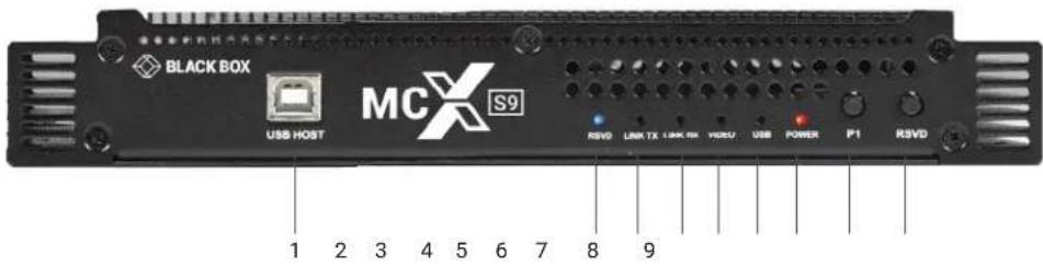
FIGURE 2-1. FRONT PANEL (MCX-S9-ENC OR MCX-S9D-ENC SERIES UNIT)
TABLE 2-2. FRONT-PANEL (MCX-S9-ENC OR MCX-S9D-ENC SERIES UNIT) COMPONENTS
| NUMBER IN FIGURE 2-1 COMPONENT DESCRIPTION | |
| 1 (1) USB Type B port Connect to a host computer. | |
| 2 (1) RSVD LED Reserved for future use. | |
| 3 (1) Link TX LED | Blinking: The device is sending Ethernet data.Off: The device is not sending Ethernet data. |
| 4 (1) Link RX LED | On: The device is processing the video signal but is not receiving Ethernet data.Off: The device is not processing the video signal nor receiving Ethernet data.Blinking: The device is processing the video signal and receiving Ethernet data. |
| 5 (1) Video LED | On: A stable video signal is detected.Off: No stable video signal is detected. |
| 6 (1) USB LED Blinking: A USB device is connected. | |
| 7 (1) Power LED | On: The encoder is powered on.Off: The encoder is powered off. |
| 8 (1) P1 button Press once to select input from HDMI or DisplayPort. | |
| 9 (1) RSVD button Reserved for future use. | |
MCX-S9-ENC or MCX-S9D-ENC Series Unit Back Panel
Figure 2-2 shows the back panel of the MCX-S9-ENC or MCX-S9D-ENC series unit. Table 2-3 describes its components.
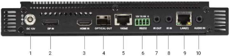
FIGURE 2-2. BACK PANEL (MCX-S9-ENC OR MCX-S9D-ENC SERIES UNIT)
TABLE 2-3. BACK-PANEL (MCX-S9-ENC OR MCX-S9D-ENC SERIES UNIT) COMPONENTS
| NUMBER IN FIGURE 2-2 COMPONENT DESCRIPTION | ||
| 1 | (1) 12-VDC power connector | Connect to the power adapter provided. |
| 2 | (1) DisplayPort in connector | Connect this port to a DisplayPort source device. |
| 3 | (1) HDMI in connector | Connect this port to an HDMI source device. |
| 4 (1) Optical OUT port | Connect this 10GbE fiber port to a 10GbE Ethernet switch for IP stream output using a 10GbE SFP+ fiber optic transceiver. | |
| 5 (1) 10GbE OUT port Connect this 10GbE copper port to a 10GbE Ethernet switch for IP stream output. | ||
| 6 (1) RS-232 port | Connect this port to an RS-232 device such as a computer for bidirectional serial communication with an RS-232 device connected to another MCX-S9 unit on the network. | |
| 7 IR OUT | Connect to an IR transmitter for IR communication with an IR receiver in another MCX-S9 series unit on the network. | |
| 8 IR IN | Connect to an IR receiver for IR communication with an IR transmitter in another MCX-S9 series unit on the network. | |
| 9 (1) RJ-45 LAN port | 10/100/1000BASE-T: Connect this port to a switch, a router or a computer for signal routing, device management, and device upgrading via control software PC configurator. | |
| 10 | Audio IN | Connect to an audio input device, such as a computer or a mobile phone, for audio input. |
2.6.2 MCX-S9-DEC UNIT
MCX-S9-DEC Series Unit Front Panel
Figure 2-3 shows the front panel of the MCX-S9-DEC series unit. Table 2-4 describes its components.
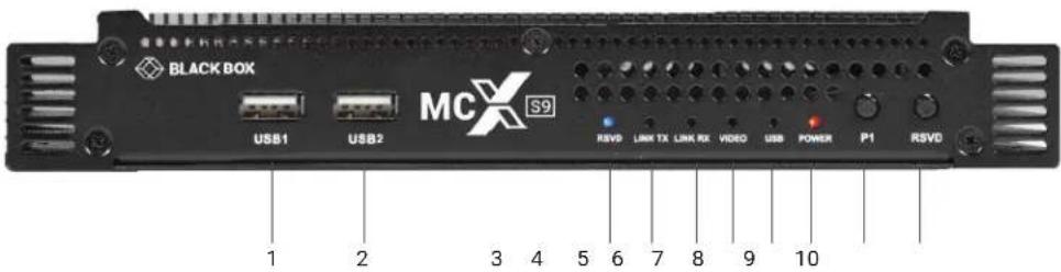
FIGURE 2-3. FRONT PANEL (MCX-S9-DEC SERIES UNIT)
TABLE 2-4. FRONT PANEL (MCX-S9-DEC SERIES UNIT) COMPONENTS
| NUMBER IN FIGURE 2-3 COMPONENT DESCRIPTION | ||
| 1, 2 | (2) USB Type A ports | Connect to a USB device such as a keyboard or mouse. |
| 3 (1) RSVD LED Reserved for future use. | ||
| 4 (1) Link TX LED | Blinking: The device is sending Ethernet data.Off: The device is not sending Ethernet data. | |
| 5 (1) Link RX LED | On: The device is processing the video signal but is not receiving Ethernet data.Off: The device is not processing the video signal nor receiving Ethernet data.Blinking: The device is processing the video signal and receiving Ethernet data. | |
| 6 (1) Video LED | On: A stable video signal is detected.Off: No stable video signal is detected. | |
| 7 (1) USB LED Blinking: A USB device is connected. | ||
| 8 (1) Power LED | On: The encoder is powered on.Off: The encoder is powered off. | |
| 9 | (1) P1 button | Press once to copy the connected HDMI display's EDID to all MCX transmitters in the network. |
| 10 | (1) RSVD button | Reserved for future use. |
CHAPTER 2: OVERVIEW
NEED HELP? LEAVE THE TECH TO US
LIVE 24/7 TECHNICAL SUPPORT
1.87 7.877.2269
MCX-S9-DEC Series Units Back Panel
Figure 2-4 shows the front panel of the MCX-S9-DEC series unit. Table 2-5 describes its components.
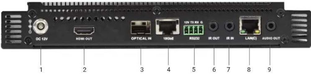
FIGURE 2-4. BACK PANEL (MCX-S9-DEC SERIES UNIT)
TABLE 2-5. BACK PANEL (MCX-S9-DEC SERIES UNIT) COMPONENTS
| NUMBER IN FIGURE 2-4 COMPONENT DESCRIPTION | ||
| 1 | (1) 12-VDC power connector | Connect to the power adapter provided. |
| 2 | (1) HDMI Out connector | Connect this port to an HDMI display device. |
| 3 (1) Optical IN port | Connect this 10GbE fiber port to a 10GbE Ethernet switch for IP stream input using a 10GbE SFP+ fiber optic transceiver. | |
| 4 (1) 10GbE IN port Connect this 10GbE copper port to a 10GbE Ethernet switch for IP stream output. | ||
| 5 (1) RS-232 port | Connect this port to an RS-232 device such as a computer for bidirectional serial communication with an RS-232 device connected to another MCX-S9 unit on the network. | |
| 6 IR OUT | Connect to an IR transmitter for IR communication with an IR receiver in another MCX-S9 series unit on the network. | |
| 7 IR IN | Connect to an IR receiver for IR communication with an IR transmitter in another MCX-S9 series unit on the network. | |
| 8 (1) RJ-45 LAN port | 10/100/1000 BASE-T: Connect this port to a switch, a router or a computer for signal routing, device management, and device upgrading via control software PC configurator. | |
| 9 Audio OUT | Connect to an audio output device, such as an amplifier, speaker, or an earphone for audio output. | |
2.6.3 MCX-S9C-ENC UNIT
MCX-S9C-ENC Series Unit Front Panel
Figure 2-5 shows the front panel of the MCX-S9C-ENC series unit. Table 2-6 describes its components.
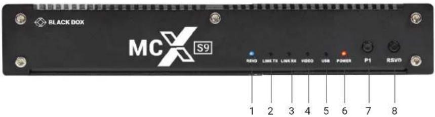
FIGURE 2-5. FRONT PANEL (MCX-S9C-ENC SERIES UNIT)
TABLE 2-6. FRONT PANEL (MCX-S9C-ENC SERIES UNIT) COMPONENTS
| NUMBER IN FIGURE 2-5 COMPONENT DESCRIPTION | |
| 1 (1) RSVD LED Reserved for future use. | |
| 2 (1) Link TX LED | Blinking: The device is sending Ethernet data.Off: The device is not sending Ethernet data. |
| 3 (1) Link RX LED | On: The device is processing the video signal but is not receiving Ethernet data.Off: The device is not processing the video signal nor receiving Ethernet data.Blinking: The device is processing the video signal and receiving Ethernet data. |
| 4 (1) Video LED | On: A stable video signal is detected.Off: No stable video signal is detected. |
| 5 (1) USB LED Blinking: A USB device is connected. | |
| 6 (1) Power LED | On: The encoder is powered on.Off: The encoder is powered off. |
| 7 (1) P1 button Press once to select input from HDMI or DisplayPort. | |
| 8 (1) RSVD button Reserved for future use. | |
CHAPTER 2: OVERVIEW
NEED HELP? LEAVE THE TECH TO US
LIVE 24/7 TECHNICAL SUPPORT
1.87 7.877.2269
MCX-S9C-ENC Series Unit Back Panel
Figure 2-6 shows the back panel of the MCX-S9C-ENC series unit. Table 2-7 describes its components.
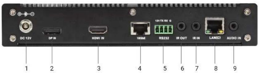
FIGURE 2-6. BACK PANEL (MCX-S9C-ENC SERIES UNIT)
TABLE 2-7. BACK PANEL (MCX-S9C-ENC SERIES UNIT) COMPONENTS
| NUMBER IN FIGURE 2-6 COMPONENT DESCRIPTION | ||
| 1 | 12-VDC power connector | Connect to the power adapter provided. |
| 2 | (1) DisplayPort in connector | Connect this port to a DisplayPort source device. |
| 3 | (1) HDMI in connector | Connect this port to an HDMI source device. |
| 4 (1) 10GbE OUT port Connect this 10GbE copper port to a 10GbE Ethernet switch for IP stream output. | ||
| 5 (1) RS-232 port | Connect this port to an RS-232 device such as a computer for bidirectional serial communication with an RS-232 device connected to another MCX-S9 unit on the network. | |
| 6 IR OUT | Connect to an IR transmitter for IR communication with an IR receiver in another MCX-S9 series unit on the network. | |
| 7 IR IN | Connect to an IR receiver for IR communication with an IR transmitter in another MCX-S9 series unit on the network. | |
| 8 (1) RJ-45 LAN port | 10/100/1000 BASE-T: Connect this port to a switch, a router or a computer for signal routing, device management, and device upgrading via control software PC configurator. | |
| 9 | Audio IN | Connect to an audio input device, such as a computer or a mobile phone, for audio input. |
CHAPTER 2: OVERVIEW
NEED HELP?
LEAVE THE TECH TO US
LIVE 24/7
TECHNICAL
SUPPORT
1.87 7.877.2269
2.6.4 MCX-S9C-DEC UNIT
MCX-S9C-DEC Series Unit Front Panel
Figure 2-7 shows the front panel of the MCX-S9C-DEC series unit. Table 2-8 describes its components.
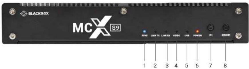
FIGURE 2-7. FRONT PANEL (MCX-S9C-DEC SERIES UNIT)
TABLE 2-8. FRONT PANEL (MCX-S9C-DEC SERIES UNIT) COMPONENTS
| NUMBER IN FIGURE 2-7 COMPONENT DESCRIPTION | |
| 1 (1) RSVD LED Reserved for future use. | |
| 2 (1) Link TX LED | Blinking: The device is sending Ethernet data.Off: The device is not sending Ethernet data. |
| 3 (1) Link RX LED | On: The device is processing the video signal but is not receiving Ethernet data.Off: The device is not processing the video signal nor receiving Ethernet data.Blinking: The device is processing the video signal and receiving Ethernet data. |
| 4 (1) Video LED | On: A stable video signal is detected.Off: No stable video signal is detected. |
| 5 (1) USB LED Blinking: A USB device is connected. | |
| 6 (1) Power LED | On: The encoder is powered on.Off: The encoder is powered off. |
| 7 (1) P1 button Press once to copy the connected HDMI display's EDID to all MCX transmitters in the network. | |
| 8 (1) RSVD button Reserved for future use. | |
CHAPTER 2: OVERVIEW
NEED HELP? LEAVE THE TECH TO US
LIVE 24/7 TECHNICAL SUPPORT
1.87 7.877.2269
MCX-S9C-DEC Series Unit Back Panel
Figure 2-8 shows the back panel of the MCX-S9C-DEC series unit. Table 2-9 describes its components.
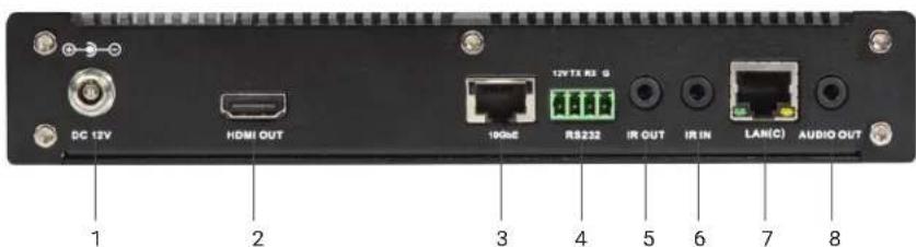
FIGURE 2-8. BACK PANEL (MCX-S9C-DEC SERIES UNIT)
TABLE 2-9. BACK PANEL (MCX-S9C-DEC SERIES UNIT) COMPONENTS
| NUMBER IN FIGURE 2-8 COMPONENT DESCRIPTION | ||
| 1 | 12-VDC power connector | Connect to the power adapter provided. |
| 2 HDMI OUT Connect to an HDMI display source. | ||
| 3 10GbE IN Connect this 10GbE copper port to a 10GbE Ethernet switch for IP stream input. | ||
| 4 RS-232 | Connect to an RS-232 device, such as a PC, for bi-directional serial communication with an RS-232 device connected to another MCX-S7 series unit on the network. | |
| 5 IR OUT | Connect to an IR transmitter for IR communication with an IR receiver in another MCX-S7 series unit on the network. | |
| 6 IR IN | Connect to an IR receiver for IR communication with an IR transmitter in another MCX-S7 series unit on the network. | |
| 7 LAN | 10/100/1000 BASE-T: Connect this port to a switch, a router or a computer for signal routing, device management, and device upgrading via control software PC configurator. | |
| 8 | Audio OUT | Connect to an audio receiver such as an amplifier, a speaker or an earphone for audio input. |
CHAPTER 3: TYPICAL APPLICATIONS
NEED HELP?
LEAVE THE TECH TO US
LIVE 24/7
TECHNICAL
SUPPORT
1.87 7.877.2269
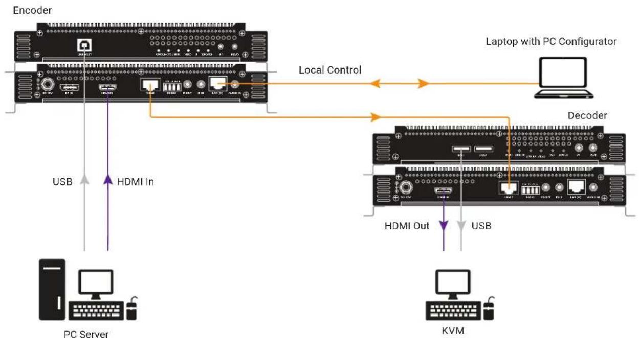
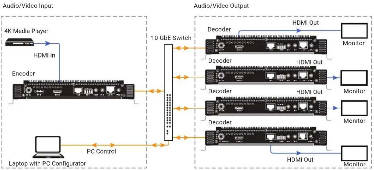
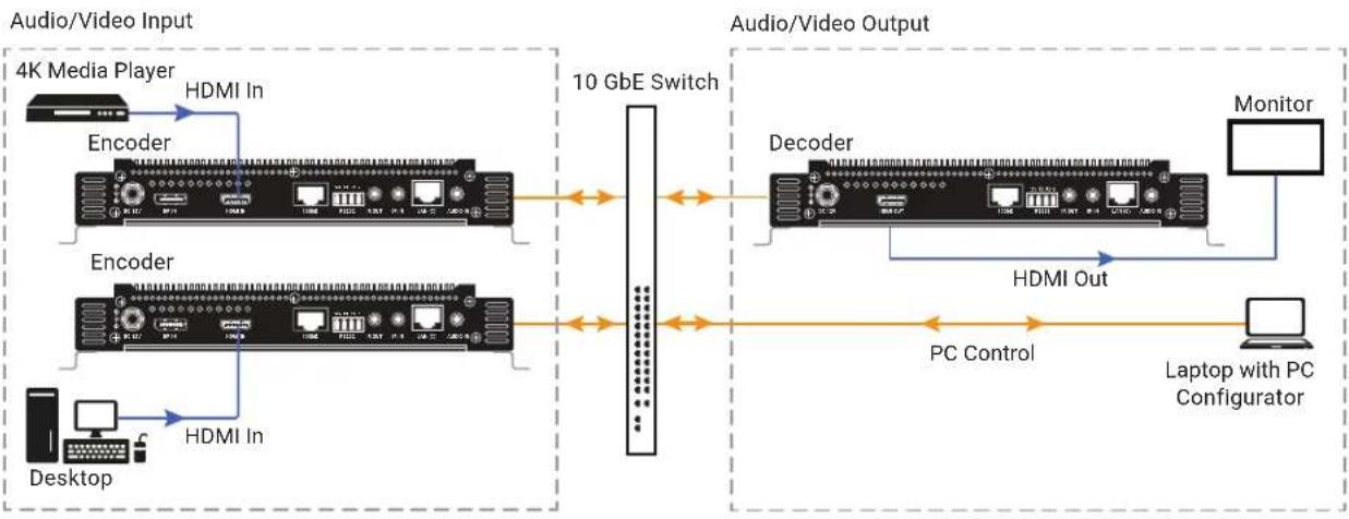
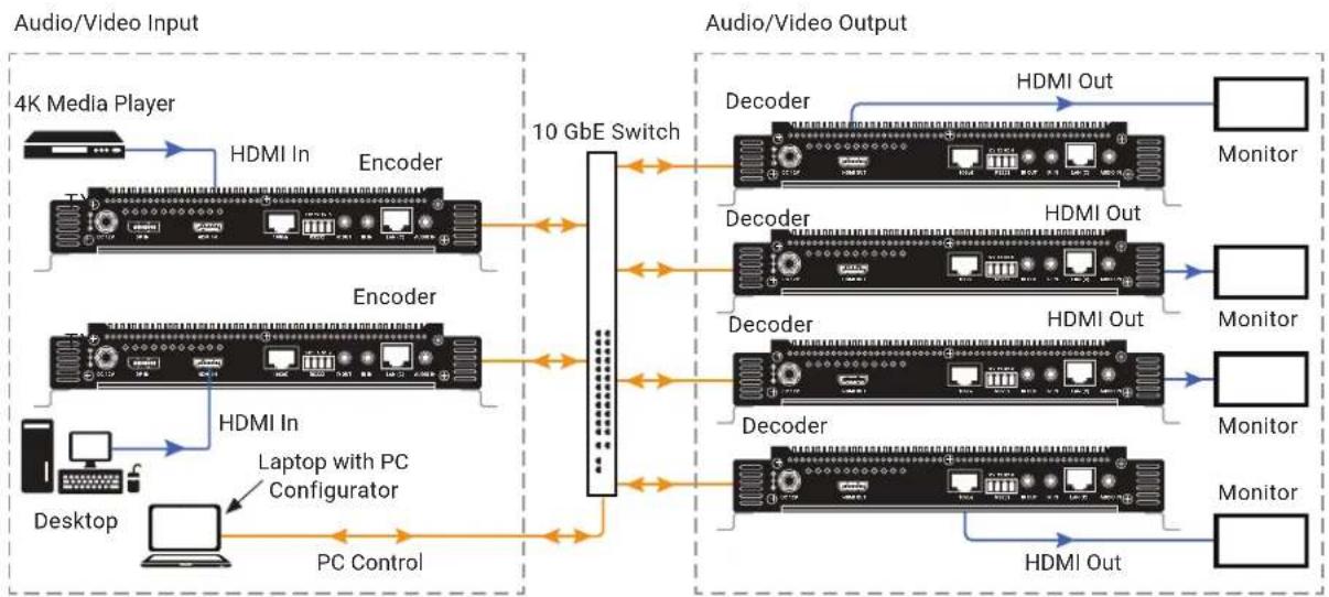
MCX-S9 series units allow any model of encoder and decoder to be linked, offering various applications to meet your requirements.
The following four typical applications are available for your reference: Point-to-Point, Point-to-Multipoint, Multipoint-to-Multipoint, and Multipoint-to-Point.
This section uses units with 10GbE copper ports as an example.
The fiberoptic ports' cabling configuration is similar.
3.1 POINT-TO-POINT
flowchart
graph TD
    A["Encoder"] -->|Local Control| B["Laptop with PC Configurator"]
    A -->|HDMI In| C["PC Server"]
    A -->|HDMI Out| D["KVM"]
    B --> E["Decoder"]
    C --> F["Local Control"]
    D --> G["Local Control"]
FIGURE 3-1. POINT-TO-POINT APPLICATION
3.2 POINT-TO-MULTIPOINT
flowchart
graph LR
    A["4K Media Player"] -->|HDMI In| B["Encoder"]
    B --> C["10 GbE Switch"]
    C --> D["Decoder"]
    D --> E["HDMI Out"]
    D --> F["Monitor"]
    C --> G["Decoder"]
    G --> H["HDMI Out"]
    G --> I["Monitor"]
    C --> J["Decoder"]
    J --> K["HDMI Out"]
    J --> L["Monitor"]
    C --> M["Laptop with PC Configurator"]
    M --> N["PC Control"]
    N --> C
    style A fill:#f9f,stroke:#333
    style B fill:#ccf,stroke:#333
    style C fill:#cfc,stroke:#333
    style D fill:#fcc,stroke:#333
    style E fill:#cff,stroke:#333
    style F fill:#ffc,stroke:#333
    style G fill:#cff,stroke:#333
    style H fill:#ffc,stroke:#333
    style I fill:#ffc,stroke:#333
    style J fill:#cff,stroke:#333
    style K fill:#ffc,stroke:#333
    style L fill:#ffc,stroke:#333
FIGURE 3-2. POINT-TO-MULTIPOINT APPLICATION
CHAPTER 3: TYPICAL APPLICATIONS
NEED HELP?
LEAVE THE TECH TO US
LIVE 24/7
TECHNICAL
SUPPORT
1.87 7.877.2269
3.3 MULTIPOINT-TO-POINT
flowchart
graph LR
    A["4K Media Player"] -->|HDMI In| B["Encoder"]
    C["Desktop"] -->|HDMI In| D["Encoder"]
    B --> E["10 GbE Switch"]
    D --> E
    E --> F["Decoder"]
    F --> G["HDMI Out"]
    G --> H["Laptop with PC Configurator"]
    H --> I["Monitor"]
    style A fill:#f9f,stroke:#333
    style C fill:#f9f,stroke:#333
    style B fill:#ccf,stroke:#333
    style D fill:#ccf,stroke:#333
    style F fill:#cfc,stroke:#333
    style G fill:#fcc,stroke:#333
    style H fill:#cff,stroke:#333
    style I fill:#ffc,stroke:#333
FIGURE 3-3. MULTIPOINT-TO-POINT APPLICATION
3.4 MULTIPOINT-TO-MULTIPOINT
flowchart
graph LR
    A["4K Media Player"] -->|HDMI In| B["Encoder"]
    B --> C["10 GbE Switch"]
    D["Desktop"] -->|HDMI In| E["Laptop with PC Configurator"]
    E --> F["PC Control"]
    F --> C
    C --> G["Decoder"]
    G --> H["HDMI Out"]
    G --> I["Monitor"]
    E --> J["Decoder"]
    J --> K["HDMI Out"]
    J --> L["Monitor"]
    E --> M["Decoder"]
    M --> N["HDMI Out"]
    M --> O["Monitor"]
    G --> P["HDMI Out"]
    P --> Q["Monitor"]
FIGURE 3-4. MULTIPOINT-TO-MULTIPOINT APPLICATION
CHAPTER 4: HARDWARE INSTALLATION
NEED HELP?
LEAVE THE TECH TO US
LIVE 24/7
TECHNICAL
SUPPORT
1.87 7.877.2269
WARNINGS:
Before the installation, disconnect the power supplies from all the devices.
Transmitter and receiver modules in fiber optic transceivers should be correctly connected to separate fiber cables.
This section uses units with 10GbE copper ports as an example. The fiberoptic units' cabling is similar.
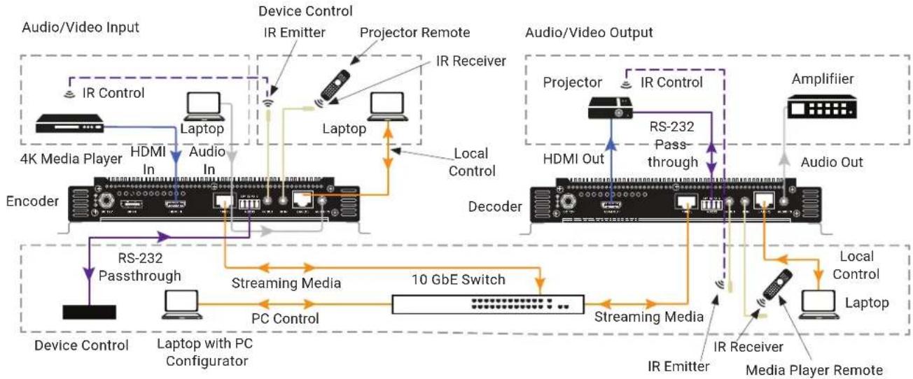
flowchart
graph TD
    subgraph Audio/Video Input
        A["4K Media Player"] -->|IR Control| B["Laptop"]
        B -->|Laptop| C["Encoder"]
        C -->|HDMI In| D["Local Control"]
        D --> E["Device Control"]
        E --> F["Laptop with PC Configurator"]
    end

    subgraph Audio/Video Output
        G["Projector"] --> H["IRS Control"]
        H --> I["HDMI Out"]
        I --> J["Decoder"]
        J --> K["Amplifier"]
        K --> L["Radio Receiver"]
        L --> M["Media Player Remote"]
    end

    C -->|RS-232 Passthrough| N["10 GbE Switch"]
    N --> O["Streaming Media"]
    O --> P["PC Control"]
    P --> Q["Local Control"]
    Q --> R["Laptop"]
    R --> S["Data Driver"]
    S --> T["Device Control"]
    T --> U["Laptop with PC Configurator"]
    U --> V["Local Control"]
    V --> W["Radio Receiver"]
    W --> X["Media Player Remote"]
    X --> Y["Local Control"]
    Y --> Z["Laptop with PC Configurator"]
    Z --> AA["10 GbE Switch"]
    AA --> AB["Local Control"]
    AB --> AC["Laptop with PC Configurator"]
    AC --> AD["10 GbE Switch"]
    AD --> AE["Local Control"]
    AE --> AF["Laptop with PC Configurator"]

    subgraph Audio/Video Input
        AG["Device Control"] --> AH["Laptop"]
        AH --> AI["Local Control"]
        AI --> AJ["Local Control"]
        AJ --> AK["Laptop with PC Configurator"]
        AK --> AL["Local Control"]
        AL --> AM["Laptop with PC Configurator"]
        AM --> AN["10 GbE Switch"]
        AN --> AO["Local Control"]
        AO --> AP["Laptop with PC Configurator"]
        AP --> AQ["Laptop with PC Configurator"]
        AQ --> AR["Local Control"]
        AR --> AS["Laptop with PC Configurator"]
        AS --> AT["Laptop with PC Configurator"]
        AT --> AU["Local Control"]
        AU --> AV["Laptop with PC Configurator"]
        AV --> AW["Laptop with PC Configurator"]
        AW --> AX["Laptop with PC Configurator"]
        AX --> AY["Laptop with PC Configurator"]
        AY --> AZ["Laptop with PC Configurator"]
        AZ --> BA["Laptop with PC Configurator"]
        BA --> BB["Laptop with PC Configurator"]
        BB --> BC["Laptop with PC Configurator"]
        BC --> BD["Laptop with PC Configurator"]
        BD --> BE["Laptop with PC Configurator"]
        BE --> BF["Laptop with PC Configurator"]
        BF --> BG["Laptop with PC Configurator"]
        BG --> BH["Laptop with PC Configurator"]
        BH --> BI["Laptop with PC Configurator"]
        BI --> BJ["Laptop with PC Configurator"]
        BJ --> BK["Laptop with PC Configurator"]
        BK --> BL["Laptop with PC Configurator"]
        BL --> BM["Laptop with PC Configurator"]
        BM --> BN["Laptop with PC Configurator"]
        BN --> BO["Laptop with PC Configurator"]
        BO --> BP["Laptop with PC Configurator"]
        BP --> BQ["Laptop with PC Configurator"]
        BQ --> BR["Laptop with PC Configurator"]
        BR --> BS["Laptop with PC Configurator"]
        BS --> BT["Laptop with PC Configurator"]
        BT --> BU["Laptop with PC Configurator"]
        BU --> BV["Laptop with PC Configurator"]
        BV --> BW["Laptop with PC Configurator"]
        BW --> BX["Laptop with PC Configurator"]
        BX --> BY["Laptop with PC Configurator"]
        BY --> BZ["Laptop with PC Configurator"]
        BZ --> CA["Laptop with PC Configurator"]
        CA --> CB["Laptop with PC Configurator"]
        CB --> CC["Laptop with PC Configurator"]
        CC --> CD["Laptop with PC Configurator"]
        CD --> CE["Laptop with PC Configurator"]
        CE --> CF["Laptop with PC Configurator"]
        CF --> CG["Laptop with PC Configurator"]
        CG --> CH["Laptop with PC Configurator"]
        CH --> CI["Laptop with PC Configurator"]
        CI --> CJ["Laptop with PC Configurator"]
        CJ --> CK["Laptop with PC Configurator"]
        CK --> CR["Laptop with PC Configurator"]
        CR --> CS["Laptop with PC Configurator"]
        CS --> CT["Laptop with PC Configurator"]
        CT --> CU["Laptop with PC Configurator"]
        CU --> CV["Laptop with PC Configurator"]
        CV --> CW["Laptop with PC Configurator"]
        CW --> CX["Laptop with PC Configurator"]
        CX --> CY["Laptop with PC Configurator"]
        CY --> CZ["Laptop with PC Configurator"]
        CZ --> DA["Laptop with PC Configurator"]
        DA --> DB["Laptop with PC Configurator"]
        DB --> DC["Laptop with PC Configurator"]
        DC --> DD["Laptop with PC Configurator"]
        DD --> DP["Laptop with PC Configurator"]
        DP --> DZ["Laptop with PC Configurator"]

    end
FIGURE 4-1. INSTALLATION DIAGRAM
APPENDIX A: REGULATORY INFORMATION
A.1 FCC CLASS B STATEMENT
Class B Digital Device. This equipment has been tested and found to comply with the limits for a Class B computing device pursuant to Part 15 of the FCC Rules. These limits are designed to provide reasonable protection against harmful interference in a residential installation. However, there is no guarantee that interference will not occur in a particular installation. This equipment generates, uses, and can radiate radio frequency energy, and, if not installed and used in accordance with the instructions, may cause harmful interference to radio communications. If this equipment does cause harmful interference to radio or telephone reception, which can be determined by turning the equipment off and on, the user is encouraged to try to correct the interference by one of the following measures:
◆ Reorient or relocate the receiving antenna.
- Increase the separation between the equipment and receiver.
- Connect the equipment into an outlet on a circuit different from that to which the receiver is connected.
- Consult an experienced radio/TV technician for help.
CAUTION: Changes or modifications not expressly approved by the party responsible for compliance could void the user's authority to operate the equipment.
To meet FCC requirements, shielded cables and power cords are required to connect this device to a personal computer or other Class B certified device.
This digital apparatus does not exceed the Class B limits for radio noise emission from digital apparatus set out in the Radio Interference Regulation of Industry Canada.
This product complies with CE and ROHS2 certifications.
APPENDIX A: REGULATORY INFORMATION
A.3 NOM STATEMENT
Black Box Corporation shall not be liable for damages of any kind, including, but not limited to, punitive, consequential or cost of cover damages, resulting from any errors in the product information or specifications set forth in this document and Black Box Corporation may revise this document at any time without notice.
B.2 TRADEMARKS USED IN THIS MANUAL
Black Box and the Black Box logo type and mark are registered trademarks of Black Box Corporation.
Any other trademarks mentioned in this manual are acknowledged to be the property of the trademark owners.
NOTES
NEED HELP?
LEAVE THE TECH TO US
LIVE 24/7
TECHNICAL
SUPPORT
1.87 7.877.2269
NEED HELP?
LEAVE THE TECH TO US
LIVE 24/7
TECHNICAL
SUPPORT
1.87 7.87 7.2269


- TABLE OF CONTENTS
- IMPORTANT SAFETY INSTRUCTIONS .... 4
- QUICK INSTALLATION GUIDE....5
- SPECIFICATIONS....6
- OVERVIEW....14
- TYPICAL APPLICATIONS ...... 24
- HARDWARE INSTALLATION....27
- APPENDIX A. REGULATORY INFORMATION 28
- APPENDIX B.DISCLAIMER/TRADEMARKS 30
- IMPORTANT SAFETY INSTRUCTIONS
- QUICK INSTALLATION GUIDE
- PREPARATION
- CONNECTING ONE TX TO ONE RX DIRECTLY
- CONNECTING TX TO RX
- CONFIGURING TX AND RX
- CONNECTING THE TX AND RX TO A SWITCH
- CHAPTER 1: SPECIFICATIONS
- ABOUT THIS MANUAL
- INTRODUCTION
- PORT DIFFERENCES
- FEATURES
- CHAPTER 2: OVERVIEW
- WHAT'S INCLUDED
- MCX-S9-ENC, MCX-S9D-ENC or MCX-S9C-ENC:
- MCX-S9-DEC or MCX-S9C-DEC:
- HARDWARE DESCRIPTION
- MCX-S9-ENC OR MCX-S9D-ENC UNIT
- MCX-S9-DEC UNIT
- MCX-S9-DEC Series Units Back Panel
- MCX-S9C-ENC UNIT
- MCX-S9C-ENC Series Unit Front Panel
- MCX-S9C-DEC UNIT
- MCX-S9C-DEC Series Unit Front Panel
- CHAPTER 3: TYPICAL APPLICATIONS
- POINT-TO-POINT
- POINT-TO-MULTIPOINT
- MULTIPOINT-TO-POINT
- MULTIPOINT-TO-MULTIPOINT
- CHAPTER 4: HARDWARE INSTALLATION
- WARNINGS:
- APPENDIX A: REGULATORY INFORMATION
- A.1 FCC CLASS B STATEMENT
- A.3 NOM STATEMENT
- B.2 TRADEMARKS USED IN THIS MANUAL
Brand : Black Box
Model : MCX S9
Category : Audio/video extender