SDM-HS75P - Moniteur SONY - Free user manual and instructions
Find the device manual for free SDM-HS75P SONY in PDF.
Download the instructions for your Moniteur in PDF format for free! Find your manual SDM-HS75P - SONY and take your electronic device back in hand. On this page are published all the documents necessary for the use of your device. SDM-HS75P by SONY.
USER MANUAL SDM-HS75P SONY
SDM-HS75P SDM-HS95P 2004 Sony Corporation
MODE GAME M OV I E PC AU TO
1 2 8 0 x 1 0 2 4 / 6 0Hz
ENGL I SH FRANÇA I S DEUTSCH ESPA ÑOL I TA L I ANO
1 2 8 0 x 1 0 2 4 / 6 0Hz
1 2 8 0 x 1 0 2 4 / 6 0Hz
This display is designed for use in Japan only and cannot be used in any other country.
Computer Display Operating Instructions
© 2004 Sony Corporation
The model and serial numbers are located at the rear of the unit. Record these numbers in the spaces provided below. Refer to them whenever you call upon your dealer regarding this product. Model No. Serial No.
WARNING To reduce the risk of fire or electric shock, do not expose this apparatus to rain or moisture.
Dangerously high voltages are present inside the unit. Do not open the cabinet. Refer servicing to qualified personnel only. FCC Notice This equipment has been tested and found to comply with the limits for a Class B digital device, pursuant to Part 15 of the FCC Rules. These limits are designed to provide reasonable protection against harmful interference in a residential installation. This equipment generates, uses, and can radiate radio frequency energy and, if not installed and used in accordance with the instructions, may cause harmful interference to radio communications. However, there is no guarantee that interference will not occur in a particular installation. If this equipment does cause harmful interference to radio or television reception, which can be determined by turning the equipment off and on, the user is encouraged to try to correct the interference by one or more of the following measures: – Reorient or relocate the receiving antenna. – Increase the separation between the equipment and receiver. – Connect the equipment into an outlet on a circuit different from that to which the receiver is connected. – Consult the dealer or an experienced radio/TV technician for help. You are cautioned that any changes or modifications not expressly approved in this manual could void your authority to operate this equipment.
If you have any questions about this product, you may call;
Sony Customer Information Services Center 1-800-222-7669 or http://www.sony.com/
Declaration of Conformity
SONY SDM-HS75P SDM-HS95P Responsible Party: Sony Electronics Inc.
Address: 16530 Via Esprillo, San Diego, CA 92127 U.S.A. Telephone Number: 858-942-2230 This device complies with part 15 of the FCC rules. Operation is subject to the following two conditions: (1) This device may not cause harmful interference, and (2) this device must accept any interference received, including interference that may cause undesired operation.
NOTICE This notice is applicable for USA/Canada only.
If shipped to USA/Canada, install only a UL LISTED/CSA LABELLED power supply cord meeting the following specifications: SPECIFICATIONS Plug Type Nema-Plug 5-15p Cord Type SVT or SJT, minimum 3 × 18 AWG Length Maximum 15 feet Rating
Minimum 7 A, 125 V As an ENERGY STAR Partner, Sony
Corporation has determined that this product meets the ENERGY STAR guidelines for energy efficiency.
Customizing Your Monitor . . . . . . . . . . . . . . . . . . . . . . .10
Navigating the menu. . . . . . . . . . . . . . . . . . . . . . . . . . . . . . . . . . . . 10 PICTURE menu . . . . . . . . . . . . . . . . . . . . . . . . . . . . . . . . . . . 10 SCREEN menu (analog RGB signal only) . . . . . . . . . . . . . . . 12 MENU POSITION menu . . . . . . . . . . . . . . . . . . . . . . . . . . . . . 13 INPUT SENSING menu . . . . . . . . . . . . . . . . . . . . . . . . . . . . . 14 LANGUAGE menu . . . . . . . . . . . . . . . . . . . . . . . . . . . . . . . . . 14 0 RESET menu (reset to the default setting) . . . . . . . . . . . . . . . 14 MENU LOCK menu . . . . . . . . . . . . . . . . . . . . . . . . . . . . . . . . 14 • Macintosh is a trademark licensed to Apple Computer, Inc., registered in the U.S.A. and other countries. • Windows and MS-DOS are registered trademarks of Microsoft Corporation in the United States and other countries. • IBM PC/AT and VGA are registered trademarks of IBM Corporation of the U.S.A. • VESA and DDC are trademarks of the Video Electronics Standards Association. • ENERGY STAR is a U.S. registered mark. • Adobe and Acrobat are trademarks of Adobe Systems Incorporated. • All other product names mentioned herein may be the trademarks or registered trademarks of their respective companies. • Furthermore, “” and “” are not mentioned in each case in this manual.
Note on the LCD (Liquid Crystal Display)
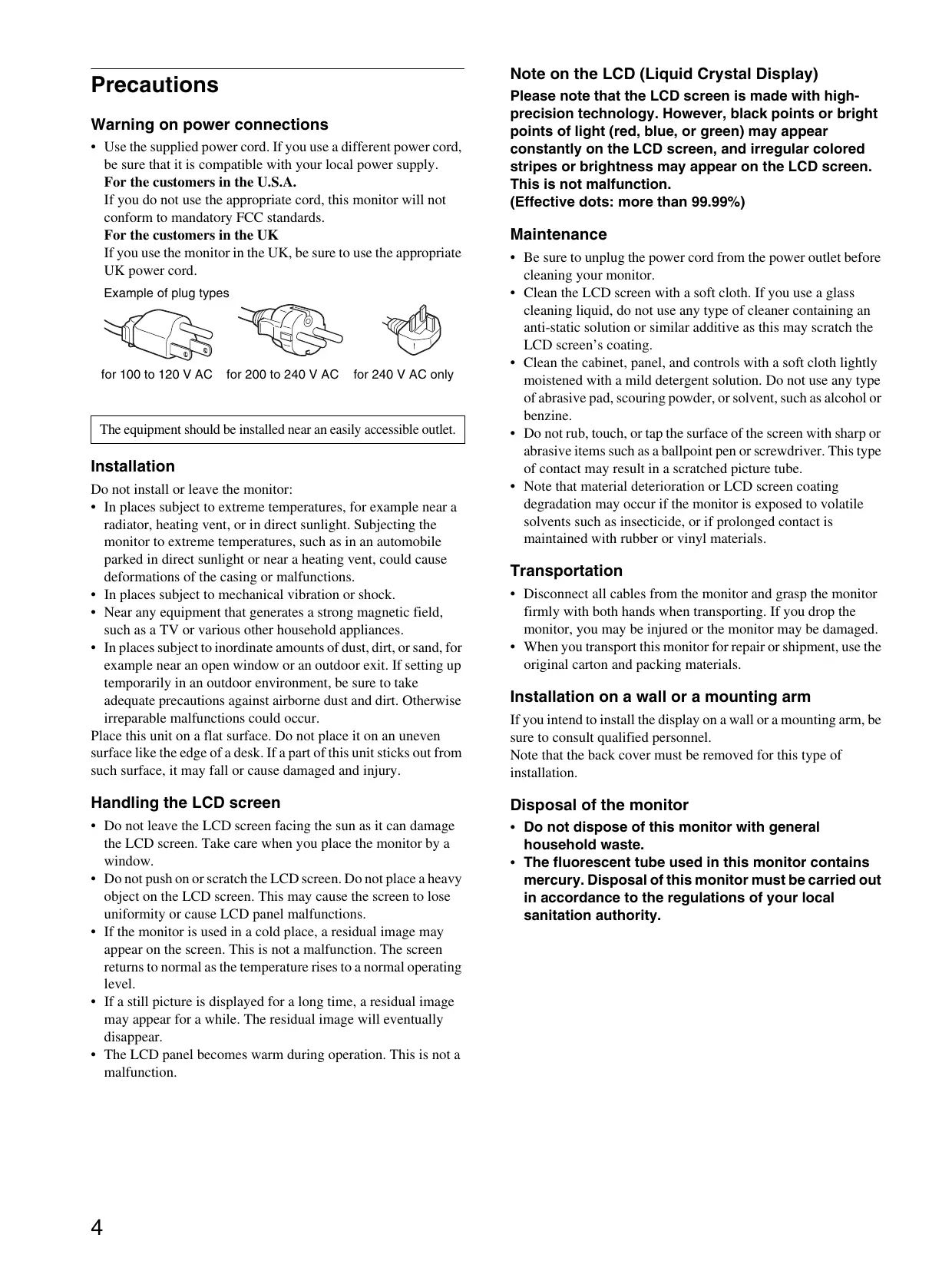
Warning on power connections • Use the supplied power cord. If you use a different power cord, be sure that it is compatible with your local power supply. For the customers in the U.S.A. If you do not use the appropriate cord, this monitor will not conform to mandatory FCC standards. For the customers in the UK If you use the monitor in the UK, be sure to use the appropriate UK power cord. Example of plug types
The equipment should be installed near an easily accessible outlet.
Do not install or leave the monitor: • In places subject to extreme temperatures, for example near a radiator, heating vent, or in direct sunlight. Subjecting the monitor to extreme temperatures, such as in an automobile parked in direct sunlight or near a heating vent, could cause deformations of the casing or malfunctions. • In places subject to mechanical vibration or shock. • Near any equipment that generates a strong magnetic field, such as a TV or various other household appliances. • In places subject to inordinate amounts of dust, dirt, or sand, for example near an open window or an outdoor exit. If setting up temporarily in an outdoor environment, be sure to take adequate precautions against airborne dust and dirt. Otherwise irreparable malfunctions could occur. Place this unit on a flat surface. Do not place it on an uneven surface like the edge of a desk. If a part of this unit sticks out from such surface, it may fall or cause damaged and injury.
Please note that the LCD screen is made with highprecision technology. However, black points or bright points of light (red, blue, or green) may appear constantly on the LCD screen, and irregular colored stripes or brightness may appear on the LCD screen.
This is not malfunction. (Effective dots: more than 99.99%)
• Be sure to unplug the power cord from the power outlet before cleaning your monitor. • Clean the LCD screen with a soft cloth. If you use a glass cleaning liquid, do not use any type of cleaner containing an anti-static solution or similar additive as this may scratch the LCD screen’s coating. • Clean the cabinet, panel, and controls with a soft cloth lightly moistened with a mild detergent solution. Do not use any type of abrasive pad, scouring powder, or solvent, such as alcohol or benzine. • Do not rub, touch, or tap the surface of the screen with sharp or abrasive items such as a ballpoint pen or screwdriver. This type of contact may result in a scratched picture tube. • Note that material deterioration or LCD screen coating degradation may occur if the monitor is exposed to volatile solvents such as insecticide, or if prolonged contact is maintained with rubber or vinyl materials.
• Disconnect all cables from the monitor and grasp the monitor firmly with both hands when transporting. If you drop the monitor, you may be injured or the monitor may be damaged. • When you transport this monitor for repair or shipment, use the original carton and packing materials.
Installation on a wall or a mounting arm
If you intend to install the display on a wall or a mounting arm, be sure to consult qualified personnel. Note that the back cover must be removed for this type of installation.
Handling the LCD screen
Disposal of the monitor
• Do not leave the LCD screen facing the sun as it can damage the LCD screen. Take care when you place the monitor by a window.
• Do not push on or scratch the LCD screen. Do not place a heavy object on the LCD screen. This may cause the screen to lose uniformity or cause LCD panel malfunctions. • If the monitor is used in a cold place, a residual image may appear on the screen. This is not a malfunction. The screen returns to normal as the temperature rises to a normal operating level. • If a still picture is displayed for a long time, a residual image may appear for a while. The residual image will eventually disappear. • The LCD panel becomes warm during operation. This is not a malfunction.
• Do not dispose of this monitor with general household waste.
• The fluorescent tube used in this monitor contains mercury. Disposal of this monitor must be carried out in accordance to the regulations of your local sanitation authority.
Identifying parts and controls
See the pages in parentheses for further details. The 1 (power) switch and the control buttons are on the lower right part of the front of the monitor.
1 1 (Power) switch and indicator (pages 9, 15)
To turn the display on or off, press the 1 (power) switch upward. The power indicator lights up in green when the display is turned on, and lights up in orange when the monitor is in power saving mode.
Front of the display
Press upward to turn the display on or off.
3 m/M buttons (page 10)
These buttons function as the m/M buttons when selecting the menu items and making adjustments.
4 OK button (page 10)
This button selects the item or executes the settings in the menu.
This button is used to change the brightness of the screen.
6 INPUT button (page 9)
This button switches the video input signal between INPUT1 and INPUT2 when two computers are connected to the monitor.
7 Light sensor (page 16)
This sensor measures the brightness of the surrounding area. Be sure not to cover the sensor with papers, etc. 8
8 Security Lock Hole
The security lock hole should be applied with the Kensington Micro Saver Security System. Micro Saver Security System is a trademark of Kensington.
9 Back cover (page 8)
Remove this cover when you connect/disconnect cables or cords.
0 AC IN connector (page 8)
Connect the power cord (supplied). qa DVI-D input connector (digital RGB) for INPUT1 (page 7) This connector inputs digital RGB video signals that comply with DVI Rev.1.0. qs HD15 input connector (analog RGB) for INPUT2 (page 7) This connector inputs analog RGB video signals (0.7 Vp-p, positive) and SYNC signals.
Remove the back cover.
Connect a computer equipped with an HD15 output connector (analog RGB)
Before using your monitor, check that the following items are included in your carton: • LCD display • Power cord • HD15-HD15 video signal cable (analog RGB) • DVI-D video signal cable (digital RGB) • Cord strap • CD-ROM (utility software for Windows/Macintosh, Operating Instructions, etc.) • Warranty card • Quick Setup Guide
Using the supplied HD15-HD15 video signal cable (analog RGB), connect the computer to the monitor’s HD15 input connector (analog
RGB). Connect the computer according to the following illustrations.
x Connecting to an IBM PC/AT or compatible computer
to the HD15 input connector
Step 1: Open the stand
Note The stand is folded at the factory. Be sure not to place the display vertically with the stand as it is. Otherwise, the display may topple over.
to the computer’s HD15 output connector
IBM PC/AT or compatible computer
Step 2: Connect the display to your computer
Turn off the monitor and computer before connecting.
HD15-HD15 video signal cable (analog RGB)
x Connecting to a Macintosh computer
When connecting this monitor to a Macintosh computer, use the Macintosh adapter (not supplied) if necessary. Connect the Macintosh adapter to the computer before connecting the cable.
• Do not touch the pins of the video signal cable connector as this might bend the pins. • Check the alignment of the HD15 connector to prevent bending the pins of the video signal cable connector.
to the HD15 input connector
Connect a computer equipped with a DVI output connector (digital RGB)
Using the supplied DVI-D video signal cable (digital RGB), connect the computer to the monitor’s DVI-D input connector (digital RGB)
to the DVI-D input connector
to the computer’s output connector
HD15-HD15 video signal cable (analog
Macintosh computer to the computer’s
DVI output connector (digital RGB) DVI-D video signal cable (digital RGB) (supplied)
Step 3: Connect the power cord
With the monitor and computer switched off, first connect the power cord to the monitor, then connect it to a power outlet.
Step 4: Secure the cords and replace the back cover
1 Bundle the cables and cords. Using the supplied cord strap, bundle the cables and cords.
The illustration of the back of the monitor shown here is that of the SDM-HS75P.
The same applies for the other models.
power cord (supplied)
2 Replace the back cover.
Step 5: Turn on the monitor and computer
This display can be adjusted within the angles shown below. Approx. 20°
1 Press the 1 (power) switch upward.
The 1 (power) indicator of the monitor lights up in green.
2 Turn on the computer.
The installation of your monitor is complete. If necessary, use the monitor’s controls to adjust the picture.
Grasp the lower sides of the LCD panel, then adjust screen tilt.
If no picture appears on your screen
• Check that the power cord and the video signal cable are properly connected. • If NO INPUT SIGNAL appears on the screen: The computer is in the power saving mode. Try pressing any key on the keyboard or moving the mouse.
• If CABLE DISCONNECTED appears on the screen:
Check that the video signal cable is properly connected. • If OUT OF RANGE appears on the screen: Reconnect the old monitor. Then adjust the computer’s graphics board within the following ranges.
Analog RGB Digital RGB Horizontal frequency
1280 × 1024 or less 1280 × 1024 or less
For more information about the on-screen messages, see “Trouble symptoms and remedies” on page 18.
No need for specific drivers The monitor complies with the “DDC” Plug & Play standard and automatically detects all the monitor’s information. No specific driver needs to be installed to the computer. The first time you turn on your computer after connecting the monitor, the setup Wizard may appear on the screen. In this case, follow the on-screen instructions. The Plug & Play monitor is automatically selected so that you can use this monitor. The vertical frequency turns to 60 Hz. Since flickers are unobtrusive on the monitor, you can use it as it is. You do not need to set the vertical frequency to any particular high value.
To use the display comfortably
This display is designed so that you can set it up at a comfortable viewing angle. Adjust the viewing angle of your display according to the height of the desk and chair, and so that light is not reflected from the screen to your eyes. Note When adjusting the screen tilt, make sure not to knock or drop the display off the desk.
Selecting the input signal
(INPUT button) Press the INPUT button. The input signal change each time you press this button.
INPUT On-screen message
(Appears about 5 seconds on the upper left corner.)
Input signal configuration
INPUT1 : DVI-D DVI-D input connector
(digital RGB) for INPUT1
Customizing Your Monitor
Before making adjustments Connect the monitor and the computer, and turn them on. Wait for at least 30 minutes before making adjustments for the best result. You can make numerous adjustments to your monitor using the on-screen menu.
You can adjust the following items using PICTURE menu.
• MODE P I CTURE (GAME/MOVIE/PC/AUTO) M OV I E • BACKLIGHT 6 • CONTRAST 6 • BRIGHTNESS • GAMMA 1 2 8 0 x 1 0 2 4 / 6 0Hz EX I T • COLOR • SHARPNESS • MODE RESET 0
Navigating the menu x Using the MENU, m/M, and OK buttons
1 Display the main menu. Press the MENU button to display the main menu on your screen.
You can select the appropriate screen brightness for your purpose. The PICTURE settings can be set for each mode. The changed setting is automatically applied for each input (INPUT1/INPUT2). 1
Press the MENU button.
The main menu appears on the screen.
Press the m/M button to select
(PICTURE) and press the OK button. The PICTURE menu appears on the screen.
Press the m/M button to select “MOVIE” and press the OK button.
The MODE menu appears on the screen.
2 Select the menu you want to adjust.
Press the m/M buttons to display the desired menu. Press the OK button to select the menu item.
GAME M OV I E PC AU TO
Press the m/M buttons to make the adjustment, then press the OK button. When you press the OK button, the setting is stored, then the display returns to the previous menu.
1 2 8 0 x 1 0 2 4 / 6 0Hz
, 4 Close the menu. Press the MENU button once to return to normal viewing. If no buttons are pressed, the menu closes automatically after about 45 seconds.
MENU Press the m/M button to select the desired mode and press the OK button.
The default setting is MOVIE. • GAME: Bright picture. • MOVIE: Clear picture with strong contrast. • PC: Soft tone picture. • AUTO: Automatically adjusts the screen brightness according to the brightness of the surroundings (automatic brightness adjustment function). For more information, see “Automatic brightness adjustment function (light sensor)” (page 16).
In the AUTO mode, you cannot adjust the backlight and contrast.
x Adjusting the BACKLIGHT If the screen is too bright, adjust the backlight to make the screen easier to see.
x Resetting the adjustments
You can reset the adjustments using the RESET menu. See page 14 for more information on resetting the adjustments.
Press the MENU button.
The main menu appears on the screen.
Press the m/M buttons to select
(PICTURE) and press the OK button. The PICTURE menu appears on the screen.
Press the m/M buttons to select “ GAMMA” and press the OK button.
The GAMMA menu appears on the screen.
Press the m/M buttons to select “
BACKLIGHT” and press the OK button. The “BACKLIGHT” menu appears on the screen.
Press the m/M buttons to select the desired mode and press the OK button.
Press the m/M buttons to adjust the light level and press the OK button.
x Adjusting the CONTRAST 6
x Adjusting the COLOR You can select the picture’s color level for the white color field from the default color temperature settings.
Also, if necessary, you can fine tune the color temperature.
COLOR Adjust the picture contrast.
Press the MENU button.
The main menu appears on the screen.
Press the m/M buttons to select
(PICTURE) and press the OK button. The PICTURE menu appears on the screen.
6500K sRGB USER AD J U S T 1 2 8 0 x 1 0 2 4 / 6 0Hz EX I T
Press the MENU button.
The main menu appears on the screen.
Press the m/M buttons to select “6 CONTRAST” and press the OK button.
The “CONTRAST” menu appears on the screen.
Press the m/M buttons to select
(PICTURE) and press the OK button. The PICTURE menu appears on the screen.
Press the m/M buttons to adjust the contrast and press the OK button.
Press the m/M buttons to select “ COLOR” and press the OK button.
The COLOR menu appears on the screen.
x Adjusting the BRIGHTNESS Adjust the picture brightness (black level).
Press the MENU button.
The main menu appears on the screen.
Press the m/M buttons to select
(PICTURE) and press the OK button. The PICTURE menu appears on the screen.
Press the m/M buttons to select “
BRIGHTNESS” and press the OK button. The “BRIGHTNESS” menu appears on the screen.
Press the m/M buttons to adjust the brightness and press the OK button.
x Adjusting the GAMMA You can associate the picture’s color shade on the screen with the picture’s original color shade.
GAMMA M OV I E GAMMA 1 GAMMA 2 GAMMA 3
1 2 8 0 x 1 0 2 4 / 6 0Hz
Press the MENU button.
The main menu appears on the screen.
Press the m/M buttons to select
(PICTURE) and press the OK button. The PICTURE menu appears on the screen.
Press the m/M buttons to select the desired color temperature and press the OK button.
Whites will change from a bluish hue to reddish hue as the temperature is lowered from 9300K (default setting) to 6500K. When you select “sRGB,” the colors adjust to the sRGB profile. (The sRGB color setting is an industry-standard color space protocol designed for computer products.) If you select “sRGB,” the color settings of your computer must be set to the sRGB profile.
• If a connected computer or other equipment is not sRGB-compliant, color cannot be adjusted to the sRGB profile. • While COLOR is set to sRGB, you cannot adjust CONTRAST, BRIGHTNESS or GAMMA. • You cannot select “sRGB” when the MODE menu is set to “AUTO.”
Fine tuning the color temperature
The color temperature can be set for each mode (GAME/MOVIE/PC/AUTO). 1
Press the MENU button.
The main menu appears on the screen.
Press the m/M buttons to select
(PICTURE) and press the OK button. The PICTURE menu appears on the screen.
Press the m/M buttons to select “ COLOR” and press the OK button.
The COLOR menu appears on the screen.
Press the m/M buttons to select “ADJUST” and press the OK button.
The fine tuning menu for color temperature appears on the screen.
USER A D J U S T MENT R
1 2 8 0 x 1 0 2 4 / 6 0Hz
Press the m/M buttons to select R (Red) or B (Blue) and press the OK button. Then press the m/M buttons to adjust the color temperature and press the OK button.
Since this adjustment changes the color temperature by increasing or decreasing the R and B components with respect to G (green), the G component is fixed. Press the m/M buttons to select , then press the OK button. The new color setting is stored in memory and automatically recalled whenever “User” is selected. The COLOR menu appears on the screen.
x Adjusting the SHARPNESS Adjust to sharpen the edge of images, etc.
Press the MENU button.
The main menu appears on the screen.
Press the m/M buttons to select
(PICTURE) and press the OK button. The PICTURE menu appears on the screen.
Press the m/M buttons to select “
SHARPNESS” and press the OK button. The “SHARPNESS” menu appears on the screen.
Press the m/M buttons to adjust the sharpness and press the OK button.
x MODE RESET menu (resetting every mode to the default) 0
You can reset the adjustments to the default settings. 1
Press the MENU button.
The main menu appears on the screen.
Press the m/M button to select
(PICTURE) and press the OK button. The PICTURE menu appears on the screen.
Press the m/M buttons to select “0 MODE RESET” and press the OK button.
The “MODE RESET” menu appears on the screen.
Press the m/M buttons to select the desired mode and press the OK button.
• OK: To reset every mode in the PICTURE menu to the default settings.
• CANCEL:To cancel resetting and return to the PICTURE menu.
SCREEN menu (analog RGB signal only)
You can adjust the following items using the SCREEN menu. • AUTO SCREEN • PHASE • PITCH AU TO PHASE • H CENTER P I TCH H CENTER • V CENTER V CENTER 1 2 8 0 x 1 0 2 4 / 6 0Hz
When receiving digital RGB signals from the DVI-D input connector for INPUT1, adjustment is unnecessary.
x Automatic picture quality adjustment function
When the monitor receives an input signal, it automatically adjusts the picture’s position and sharpness (phase/pitch), and ensures that a clear picture appears on the screen (page 16). Note While the automatic picture quality adjustment function is activated, only the 1 (power) switch will operate. The picture may flicker during this time, but this is not a malfunction. Simply wait a few moments until the adjustment completes. If the automatic picture quality adjustment function of this monitor seems to not completely adjust the picture You can make further automatic adjustment of the picture quality for the current input signal (See “AUTO” below). If you still need to make further adjustments to the picture quality You can manually adjust the picture’s sharpness (phase/pitch) and position (horizontal/vertical position).
These adjustments are stored in memory and automatically recalled when the monitor receives a previously input and registered input signal.
x Make further automatic adjustments to the picture quality for the current input signal
Press the MENU button.
The main menu appears on the screen.
Press the m/M buttons to select
(SCREEN) and press the OK button. The SCREEN menu appears on the screen.
Press the m/M buttons to select “AUTO” and press the OK button.
Make the appropriate adjustments of the screen’s phase, pitch and horizontal/vertical position for the current input signal and store them.
x Adjust the picture’s sharpness manually
x Adjust the picture’s position manually
(H CENTER /V CENTER)
You can adjust the picture’s sharpness as follows. This adjustment is effective when the computer is connected to the monitor’s HD15 input connector (analog RGB).
If the picture is not in the center of the screen, adjust the picture’s centering as follows.
Set the resolution to 1280 × 1024 on the computer.
Start the CD-ROM, select the area and model, and display the test pattern.
For Windows Click [Utility] t [Windows]/[Win Utility.exe]. For Macintosh Click [Utility] t [Mac]/[Mac Utility].
Press the MENU button.
The main menu appears on the screen.
Press the m/M buttons to select
(SCREEN) and press the OK button. The SCREEN menu appears on the screen.
Press the m/M buttons to select “PHASE” and press the OK button.
The “PHASE” adjustment menu appears on the screen.
Press the m/M buttons until the horizontal stripes are at a minimum.
Adjust so that the horizontal stripes are at a minimum.
Set the resolution to 1280 × 1024 on the computer.
Start the CD-ROM, select the area and model, and display the test pattern.
For Windows Click [Utility] t [Windows]/[Win Utility.exe]. For Macintosh Click [Utility] t [Mac]/[Mac Utility].
Press the MENU button.
The main menu appears on the screen.
Press the m/M buttons to select
(SCREEN) and press the OK button. The SCREEN menu appears on the screen.
Press the m/M buttons to select “H CENTER” or “V CENTER” and press the OK button.
The “H CENTER” adjustment menu or “V CENTER” adjustment menu appears on the screen.
Press the m/M buttons to center the test pattern on the screen.
Click [END] on the screen to turn off the test pattern.
Press the OK button.
The main menu appears on the screen. If vertical stripes are observed over the entire screen, adjust the pitch using the following procedures.
You can change the menu position if it is blocking an image on the screen.
MENU POS I T I ON Press the m/M buttons to select “PITCH” and press the OK button.
The “PITCH” adjustment menu appears on the screen.
10 Press the m/M buttons until the vertical stripes disappear.
Adjust so that the vertical stripes disappear.
11 Click [END] on the screen to turn off the test pattern.
1 2 8 0 x 1 0 2 4 / 6 0Hz
Press the MENU button.
The main menu appears on the screen.
Press the m/M buttons to select
(MENU POSITION) and press the OK button. The “MENU POSITION” menu appears on the screen.
Press the m/M buttons to select the desired position and press the OK button.
You can choose one of 9 positions where the menu will appear.
When you select AUTO ON in the INPUT SENSING menu, the monitor automatically detects an input signal to an input terminal, and changes the input automatically before the monitor goes into the power saving mode. I NPUT SENSING AU TO O N AU TO O F F
1 2 8 0 x 1 0 2 4 / 6 0Hz
Press the MENU button.
The main menu appears on the screen.
Press the m/M buttons to select a language and press the OK button.
• ENGLISH • FRANÇAIS: French • DEUTSCH: German • ESPAÑOL: Spanish • ITALIANO: Italian • NEDERLANDS: Dutch • SVENSKA: Swedish • : Russian • : Japanese • : Chinese
0 RESET menu (reset to the default setting)
Press the m/M buttons to select
(INPUT SENSING) and press the OK button. The INPUT SENSING menu appears on the screen.
Press the m/M buttons to select the desired mode and press the OK button.
• AUTO ON: When the selected input terminal has no input signal, or when you select an input terminal by the INPUT button on the monitor and the terminal has no input signal, the on-screen message appears (page 17) and the monitor checks the input signal to another input terminal automatically to change the input. When the input is changed, the selected input terminal is displayed on the left upper of the screen. When there is no input signal, the monitor goes into the power saving mode automatically. • AUTO OFF: The input is not changed automatically. Press the INPUT button to change the input.
1 2 8 0 x 1 0 2 4 / 6 0Hz
Press the MENU button.
The main menu appears on the screen.
Press the m/M buttons to select 0 (RESET) and press the OK button.
The RESET menu appears on the screen.
Press the m/M buttons to select the desired mode and press the OK button.
• OK: To reset all of the adjustment data to the default settings. Note that the “ LANGUAGE” setting is not reset by this method. • CANCEL:To cancel resetting and return to the menu screen.
Lock the control of buttons to prevent accidental adjustments or resetting.
ENGL I SH FRANÇA I S DEUTSCH ESPA ÑOL I TA L I ANO ON OFF
1 2 8 0 x 1 0 2 4 / 6 0Hz
1 2 8 0 x 1 0 2 4 / 6 0Hz
EX I T Press the MENU button.
The main menu appears on the screen.
Press the MENU button.
The main menu appears on the screen.
Press the m/M buttons to select
(LANGUAGE) and press the OK button. The LANGUAGE menu appears on the screen.
Press the m/M buttons to select
(MENU LOCK) and press the OK button. The MENU LOCK menu appears on the screen.
Press the m/M buttons to select either “On” or “Off.”
• ON: Only the 1 (power) switch and INPUT button will operate. If you attempt any other operation, the icon appears on the screen. • OFF: Set “ MENU LOCK” to off. If “ MENU LOCK” has been set to “ON,” when you press the MENU button, “ MENU LOCK” is automatically selected.
Power saving function This monitor meets the power-saving guidelines set by VESA, ENERGY STAR, and NUTEK. If the monitor is connected to a computer or video graphics board that is DPMS (Display Power Management Standard) for Analog input/DMPM (DVI Digital Monitor Power Management) for Digital input compliant, the monitor will automatically reduce power consumption as shown below.
SDM-HS75P Power mode
When your computer enters the “active off” mode, the input signal is cut and NO INPUT SIGNAL appears on the screen. After 5 seconds, the monitor enters the power saving mode.
** “deep sleep” is the power saving mode defined by the Environmental Protection Agency.
Setting the MODE (PICTURE)
If you press the button on the lower side of the monitor repeatedly, you can select MODE from MOVIE t PC t AUTO t GAME. When you select “AUTO,” the monitor automatically adjusts the screen brightness according to the brightness of the surroundings (Automatic brightness adjustment function). For more information, see “Automatic brightness adjustment function (light sensor)”. Press the
button, the mode changes as follows.
When the monitor receives an input signal, it automatically matches the signal to one of the factory preset modes stored in the monitor’s memory to provide a high quality picture at the center of the screen. If the input signal matches the factory preset mode, the picture appears on the screen automatically with the appropriate default adjustments.
If input signals do not match one of the factory preset modes
: GAME Each mode appears on the screen and MODE is changed. The menu automatically disappears after about 5 seconds.
Automatic brightness adjustment function (light sensor)
This monitor is provided with a feature to automatically adjust the screen brightness according to the brightness of the surroundings. The brightness of the screen is set to the most appropriate level by button on the lower side of setting MODE to AUTO with the the monitor, or in the PICTURE menu. The default setting of the brightness of the screen is set to MOVIE. Also, when you set MODE to AUTO with the button, the adjustment bar is also displayed. You can adjust the bar with the m/M buttons. Screen brightness changes according to the level you set.
When the monitor receives an input signal, it automatically adjusts the picture’s position and sharpness (phase/pitch), and ensures that a clear picture appears on the screen.
The factory preset mode
The default setting of MODE is set to “MOVIE.” When you press the button once, “MOVIE” (the default setting) is displayed, and when you press again, “PC” is displayed.
Each time you press the
Automatic picture quality adjustment function (analog RGB signal only)
When the monitor receives an input signal that does not match one of the factory preset modes, the automatic picture quality adjustment function of this monitor is activated to ensure that a clear picture always appears on the screen (within the following monitor frequency ranges):
Horizontal frequency: 28–80 kHz Vertical frequency: 48–75 Hz Consequently, the first time the monitor receives input signals that do not match one of the factory preset modes, the monitor may take a longer time than normal to display the picture on the screen. This adjustment data is automatically stored in memory so that next time, the monitor will function in the same way as when the monitor receives the signals that match one of the factory preset modes.
If you adjust the phase, pitch, and picture position manually
For some input signals, the automatic picture quality adjustment function of this monitor may not completely adjust the picture position, phase, and pitch. In this case, you can set these adjustments manually (page 13). If you set these adjustments manually, they are stored in memory as user modes and automatically recalled whenever the monitor receives the same input signals. Note While the automatic picture quality adjustment function is activated, only the 1 (power) switch will operate. The picture may flicker during this time, but this is not a malfunction. Simply wait a few moments until the adjustment completes.
Before contacting technical support, refer to this section.
If there is something wrong with the input signal, one of the following messages appears on the screen. To solve the problem, see “Trouble symptoms and remedies” on page 18.
If OUT OF RANGE appears on the screen
This indicates that the input signal is not supported by the monitor’s specifications. Check the following items. I NFORMA T I ON OUT OF RANGE I NPUT 1 : DV I – D x x x . x kHz / x x xHz
If “xxx.x kHz/xxx Hz” is displayed
This indicates that either the horizontal or vertical frequency is not supported by the monitor’s specifications. The figures indicate the horizontal and vertical frequencies of the current input signal.
GB If “RESOLUTION > 1280 × 1024” is displayed
This indicates that the resolution is not supported by the monitor’s specifications (1280 × 1024 or less).
If NO INPUT SIGNAL appears on the screen
This indicates that no signal is being input.
I NFORMA T I ON NO I NPUT S I GNA L I NPUT 1 : DV I – D GO TO POWER SAVE GO TO POWER SAVE The monitor will enter the power saving mode after about 5 seconds from the time the message is displayed.
If CABLE DISCONNECTED appears on the screen
This indicates that the video signal cable has been disconnected. I NFORMA T I ON CAB L E D I SCONNECT ED I NPUT 1 : DV I – D
Trouble symptoms and remedies
If a problem is caused by the connected computer or other equipment, please refer to the connected equipment’s instruction manual. Symptom
If the 1 (power) indicator is not lit, or if the 1 (power) indicator will not light up when the 1 (power) switch is pressed,
• Check that the power cord is properly connected.
If CABLE DISCONNECTED appears on the screen,
• Check that the video signal cable is properly connected and all plugs are firmly seated in their sockets (page 7).
• Check that the video input connector’s pins are not bent or pushed in. • A non-supplied video signal cable is connected. If you connect a non-supplied video signal cable, CABLE DISCONNECTED may appear on the screen before entering the power saving mode. This is not a malfunction.
If NO INPUT SIGNAL appears on the screen, or the 1 (power) indicator is orange,
• Check that the video signal cable is properly connected and all plugs are firmly seated in their sockets (page 7).
• Check that the video input connector’s pins are not bent or pushed in. x Problems caused by a computer or other equipment connected, and not caused by the monitor • The computer is in the power saving mode. Try pressing any key on the keyboard or moving the mouse. • Check that your graphics board is installed properly. • Check that the computer’s power is on. • Restart the computer.
If OUT OF RANGE appears on the screen,
x Problems caused by a computer or other equipment connected, and not caused by the monitor
• Check that the video frequency range is within that specified for the monitor. If you replaced an old monitor with this monitor, reconnect the old monitor and adjust the computer’s graphics board within the following ranges: Horizontal: 28–80 kHz (analog RGB), 28–64 kHz (digital RGB) Vertical: 48–75 Hz (analog RGB), 60 Hz (digital RGB) Resolution: 1280 × 1024 or less
If you are using Windows and replaced an old monitor with this monitor,
• If you replaced an old monitor with this monitor, reconnect the old monitor and do the following. Select “SONY” from the “Manufacturers” list and select “SDM-HS75P” or
“SDM-HS95P” from the “Models” list in the Windows device selection screen. If the model name of this monitor does not appear in the “Models” list, try “Plug & Play.”
• If you use the Macintosh adapter (not supplied), check that the Macintosh adapter and the video signal cable are properly connected (page 7).
Picture flickers, bounces, oscillates, or is scrambled
• Adjust the pitch and phase (analog RGB signal only) (page 13).
• Try plugging the monitor into a different AC outlet, preferably on a different circuit. x Problems caused by a computer or other equipment connected, and not caused by the monitor • Check your graphics board manual for the proper monitor setting. • Confirm that the graphics mode (VESA, Macintosh 19" Color, etc.) and the frequency of the input signal are supported by this monitor. Even if the frequency is within the proper range, some graphics boards may have a sync pulse that is too narrow for the monitor to sync correctly. • Adjust the computer’s refresh rate (vertical frequency) to obtain the best possible picture.
• Adjust the brightness and contrast (page 11).
• Adjust the pitch and phase (analog RGB signal only) (page 13). x Problems caused by a computer or other equipment connected, and not caused by the monitor • Set the resolution to SXGA (1280 × 1024) on your computer.
• Eliminate the use of video cable extensions and/or video switch boxes.
• Check that all plugs are firmly seated in their sockets.
Picture is not centered or sized properly (analog RGB signal only)
• Adjust the pitch and phase (page 13).
• Adjust the picture position (page 13). Note that some video modes do not fill the screen to the edges.
Picture is too small
x Problems caused by a computer or other equipment connected, and not caused by the monitor
• Set the resolution to SXGA (1280 × 1024) on your computer.
Wavy or elliptical pattern (moire) is visible
• Adjust the pitch and phase (analog RGB signal only) (page 13).
Color is not uniform
• Adjust the pitch and phase (analog RGB signal only) (page 13).
White does not look white
• Adjust the color temperature (page 11).
Monitor buttons do not operate
( appears on the screen)
• If “MENU LOCK” is set to “ON”, set it to “OFF” (page 14).
The monitor turns off after a while
x Problems caused by a computer or other equipment connected, and not caused by the monitor
• Set the computer’s power saving setting to off.
Resolution displayed on the menu screen is incorrect
• Depending on the graphics board setting, the resolution displayed on the menu screen may not coincide with the one set on the computer.
Adjust the brightness (page 11).
Adjust the backlight (page 10). It takes a few minutes for the display to become bright after turning on the monitor. When the MODE menu is set to AUTO, the display brightness may become dark in low ambient light (pages 10, 16).
Displaying this monitor’s information
While the monitor is receiving a video signal, press and hold the MENU button for more than 5 seconds until the information box appears. Press the MENU button again to make the box disappear.
MENU GB If any problem persists, call your authorized Sony dealer and give the following information:
• Model name: SDM-HS75P or SDM-HS95P • Serial number • Detailed description of the problem • Date of purchase • Name and specifications of your computer and graphics board
Serial number Week and year of manufacture
SDM-HS75P SDM-HS95P LCD panel
Panel type: a-Si TFT Active Matrix
Picture size: 17.0 inch Input signal format RGB operating frequency* Horizontal: 28–80 kHz (analog RGB) 28–64 kHz (digital RGB) Vertical: 48–75 Hz (analog RGB) 60 Hz (digital RGB) Resolution Horizontal: Max.1280 dots Vertical: Max.1024 lines Input signal levels Analog RGB video signal 0.7 Vp-p, 75 Ω, positive SYNC signal TTL level, 2.2 kΩ, positive or negative (Separate horizontal and vertical) Digital RGB (DVI) signal: TMDS (Single link) Power requirements 100–240 V, 50–60 Hz, Max. 1.0 A Power consumption Max. 45 W Operating temperature 5–35°C Dimensions (width/height/depth) Display (upright): Approx. 388 × 382.5 × 139.2 mm (15 1/4 × 15 × 5 1/2 inches) Mass Approx. 5 kg (11 lb. 3/8 oz.) Plug & Play DDC2B Accessories See page 7.
Panel type: a-Si TFT Active Matrix
Picture size: 19.0 inch Input signal format RGB operating frequency* Horizontal: 28–80 kHz (analog RGB) 28–64 kHz (digital RGB) Vertical: 48–75 Hz (analog RGB) 60 Hz (digital RGB) Resolution Horizontal: Max.1280 dots Vertical: Max.1024 lines Input signal levels Analog RGB video signal 0.7 Vp-p, 75 Ω, positive SYNC signal TTL level, 2.2 kΩ, positive or negative (Separate horizontal and vertical) Digital RGB (DVI) signal: TMDS (Single link) Power requirements 100–240 V, 50–60 Hz, Max. 1.0 A Power consumption Max. 60 W Operating temperature 5–35°C Dimensions (width/height/depth) Display (upright): Approx. 435 × 418 × 146 mm (17 1/8 × 16 1/2 × 5 3/4 inches) Mass Approx. 6 kg (13 lb. 3 5/8 oz.) Plug & Play DDC2B Accessories See page 7. * Recommended horizontal and vertical timing condition • Horizontal sync width duty should be more than 4.8% of total horizontal time or 0.8 µs, whichever is larger. • Horizontal blanking width should be more than 2.5 µsec. • Vertical blanking width should be more than 450 µsec. Design and specifications are subject to change without notice.
© 2004 Sony Corporation
The model and serial numbers are located at the rear of the unit. Record these numbers in the spaces provided below. Refer to them whenever you call upon your dealer regarding this product. Model No. Serial No.
WARNING To reduce the risk of fire or electric shock, do not expose this apparatus to rain or moisture.
Dangerously high voltages are present inside the unit. Do not open the cabinet. Refer servicing to qualified personnel only. FCC Notice This equipment has been tested and found to comply with the limits for a Class B digital device, pursuant to Part 15 of the FCC Rules. These limits are designed to provide reasonable protection against harmful interference in a residential installation. This equipment generates, uses, and can radiate radio frequency energy and, if not installed and used in accordance with the instructions, may cause harmful interference to radio communications. However, there is no guarantee that interference will not occur in a particular installation. If this equipment does cause harmful interference to radio or television reception, which can be determined by turning the equipment off and on, the user is encouraged to try to correct the interference by one or more of the following measures: – Reorient or relocate the receiving antenna. – Increase the separation between the equipment and receiver. – Connect the equipment into an outlet on a circuit different from that to which the receiver is connected. – Consult the dealer or an experienced radio/TV technician for help. You are cautioned that any changes or modifications not expressly approved in this manual could void your authority to operate this equipment.
If you have any questions about this product, you may call;
Sony Customer Information Services Center 1-800-222-7669 or http://www.sony.com/
Declaration of Conformity
SONY SDM-HS75P SDM-HS95P Responsible Party: Sony Electronics Inc.
Address: 16530 Via Esprillo, San Diego, CA 92127 U.S.A. Telephone Number: 858-942-2230 This device complies with part 15 of the FCC rules. Operation is subject to the following two conditions: (1) This device may not cause harmful interference, and (2) this device must accept any interference received, including interference that may cause undesired operation.
NOTICE This notice is applicable for USA/Canada only.
If shipped to USA/Canada, install only a UL LISTED/CSA LABELLED power supply cord meeting the following specifications: SPECIFICATIONS Plug Type Nema-Plug 5-15p Cord Type SVT or SJT, minimum 3 × 18 AWG Length Maximum 15 feet Rating
Minimum 7 A, 125 V As an ENERGY STAR Partner, Sony
Corporation has determined that this product meets the ENERGY STAR guidelines for energy efficiency.
JEU FILM PC AU TO M AT I Q U E
1 2 8 0 x 1 0 2 4 / 6 0Hz
EX I T GAMMA FILM GAMMA 1
Menu LANGUAGE L A N G UA G E ENGL I SH FRANÇA I S DEUTSCH ESPA ÑOL I TA L I ANO
1 2 8 0 x 1 0 2 4 / 6 0Hz
1 2 8 0 x 1 0 2 4 / 6 0Hz EX I T
: AU TO M AT I Q U E
: JEU INFORMATIONS MODEL : SDM-HS75P SER. NO : 1234567
MANUFACTURED : 2004-52
SDM-HS75P SDM-HS95P Panneau LCD Panneau LCD SDM-HS75P SDM-HS95P
© 2004 Sony Corporation
The model and serial numbers are located at the rear of the unit. Record these numbers in the spaces provided below. Refer to them whenever you call upon your dealer regarding this product. Model No. Serial No.
WARNING To reduce the risk of fire or electric shock, do not expose this apparatus to rain or moisture.
Dangerously high voltages are present inside the unit. Do not open the cabinet. Refer servicing to qualified personnel only. FCC Notice This equipment has been tested and found to comply with the limits for a Class B digital device, pursuant to Part 15 of the FCC Rules. These limits are designed to provide reasonable protection against harmful interference in a residential installation. This equipment generates, uses, and can radiate radio frequency energy and, if not installed and used in accordance with the instructions, may cause harmful interference to radio communications. However, there is no guarantee that interference will not occur in a particular installation. If this equipment does cause harmful interference to radio or television reception, which can be determined by turning the equipment off and on, the user is encouraged to try to correct the interference by one or more of the following measures: – Reorient or relocate the receiving antenna. – Increase the separation between the equipment and receiver. – Connect the equipment into an outlet on a circuit different from that to which the receiver is connected. – Consult the dealer or an experienced radio/TV technician for help. You are cautioned that any changes or modifications not expressly approved in this manual could void your authority to operate this equipment.
If you have any questions about this product, you may call;
Sony Customer Information Services Center 1-800-222-7669 or http://www.sony.com/
Declaration of Conformity
SONY SDM-HS75P SDM-HS95P Responsible Party: Sony Electronics Inc.
Address: 16530 Via Esprillo, San Diego, CA 92127 U.S.A. Telephone Number: 858-942-2230 This device complies with part 15 of the FCC rules. Operation is subject to the following two conditions: (1) This device may not cause harmful interference, and (2) this device must accept any interference received, including interference that may cause undesired operation.
NOTICE This notice is applicable for USA/Canada only.
If shipped to USA/Canada, install only a UL LISTED/CSA LABELLED power supply cord meeting the following specifications: SPECIFICATIONS Plug Type Nema-Plug 5-15p Cord Type SVT or SJT, minimum 3 × 18 AWG Length Maximum 15 feet Rating
Minimum 7 A, 125 V As an ENERGY STAR Partner, Sony
Corporation has determined that this product meets the ENERGY STAR guidelines for energy efficiency.
SPIEL FILM PC AU TO M AT I S C H
1 2 8 0 x 1 0 2 4 / 6 0Hz
EX I T GAMMA FILM GAMMA 1
L A N G UA G E ENGL I SH FRANÇA I S DEUTSCH ESPA ÑOL I TA L I ANO
1 2 8 0 x 1 0 2 4 / 6 0Hz
: AU TO M AT I S C H
INFORMATION MODEL : SDM-HS75P SER. NO : 1234567
MANUFACTURED : 2004-52
© 2004 Sony Corporation
The model and serial numbers are located at the rear of the unit. Record these numbers in the spaces provided below. Refer to them whenever you call upon your dealer regarding this product. Model No. Serial No.
WARNING To reduce the risk of fire or electric shock, do not expose this apparatus to rain or moisture.
Dangerously high voltages are present inside the unit. Do not open the cabinet. Refer servicing to qualified personnel only. FCC Notice This equipment has been tested and found to comply with the limits for a Class B digital device, pursuant to Part 15 of the FCC Rules. These limits are designed to provide reasonable protection against harmful interference in a residential installation. This equipment generates, uses, and can radiate radio frequency energy and, if not installed and used in accordance with the instructions, may cause harmful interference to radio communications. However, there is no guarantee that interference will not occur in a particular installation. If this equipment does cause harmful interference to radio or television reception, which can be determined by turning the equipment off and on, the user is encouraged to try to correct the interference by one or more of the following measures: – Reorient or relocate the receiving antenna. – Increase the separation between the equipment and receiver. – Connect the equipment into an outlet on a circuit different from that to which the receiver is connected. – Consult the dealer or an experienced radio/TV technician for help. You are cautioned that any changes or modifications not expressly approved in this manual could void your authority to operate this equipment.
If you have any questions about this product, you may call;
Sony Customer Information Services Center 1-800-222-7669 or http://www.sony.com/
Declaration of Conformity
SONY SDM-HS75P SDM-HS95P Responsible Party: Sony Electronics Inc.
Address: 16530 Via Esprillo, San Diego, CA 92127 U.S.A. Telephone Number: 858-942-2230 This device complies with part 15 of the FCC rules. Operation is subject to the following two conditions: (1) This device may not cause harmful interference, and (2) this device must accept any interference received, including interference that may cause undesired operation.
NOTICE This notice is applicable for USA/Canada only.
If shipped to USA/Canada, install only a UL LISTED/CSA LABELLED power supply cord meeting the following specifications: SPECIFICATIONS Plug Type Nema-Plug 5-15p Cord Type SVT or SJT, minimum 3 × 18 AWG Length Maximum 15 feet Rating
Minimum 7 A, 125 V As an ENERGY STAR Partner, Sony
Corporation has determined that this product meets the ENERGY STAR guidelines for energy efficiency.
MODO JUEGO PELÍCULA PC AU TO M Á T I C A
1 2 8 0 x 1 0 2 4 / 6 0Hz
EX I T GAMMA PELÍCULA GAMMA 1
9300K 6500K sRGB USUARIO A J U S TA R 1 2 8 0 x 1 0 2 4 / 6 0Hz
EX I T A C E P TA R CANCELAR
1 2 8 0 x 1 0 2 4 / 6 0Hz
: JUEGO SDM-HS95P Panel LCD SDM-HS75P SDM-HS95P
© 2004 Sony Corporation
The model and serial numbers are located at the rear of the unit. Record these numbers in the spaces provided below. Refer to them whenever you call upon your dealer regarding this product. Model No. Serial No.
WARNING To reduce the risk of fire or electric shock, do not expose this apparatus to rain or moisture.
Dangerously high voltages are present inside the unit. Do not open the cabinet. Refer servicing to qualified personnel only. FCC Notice This equipment has been tested and found to comply with the limits for a Class B digital device, pursuant to Part 15 of the FCC Rules. These limits are designed to provide reasonable protection against harmful interference in a residential installation. This equipment generates, uses, and can radiate radio frequency energy and, if not installed and used in accordance with the instructions, may cause harmful interference to radio communications. However, there is no guarantee that interference will not occur in a particular installation. If this equipment does cause harmful interference to radio or television reception, which can be determined by turning the equipment off and on, the user is encouraged to try to correct the interference by one or more of the following measures: – Reorient or relocate the receiving antenna. – Increase the separation between the equipment and receiver. – Connect the equipment into an outlet on a circuit different from that to which the receiver is connected. – Consult the dealer or an experienced radio/TV technician for help. You are cautioned that any changes or modifications not expressly approved in this manual could void your authority to operate this equipment.
If you have any questions about this product, you may call;
Sony Customer Information Services Center 1-800-222-7669 or http://www.sony.com/
Declaration of Conformity
SONY SDM-HS75P SDM-HS95P Responsible Party: Sony Electronics Inc.
Address: 16530 Via Esprillo, San Diego, CA 92127 U.S.A. Telephone Number: 858-942-2230 This device complies with part 15 of the FCC rules. Operation is subject to the following two conditions: (1) This device may not cause harmful interference, and (2) this device must accept any interference received, including interference that may cause undesired operation.
NOTICE This notice is applicable for USA/Canada only.
If shipped to USA/Canada, install only a UL LISTED/CSA LABELLED power supply cord meeting the following specifications: SPECIFICATIONS Plug Type Nema-Plug 5-15p Cord Type SVT or SJT, minimum 3 × 18 AWG Length Maximum 15 feet Rating
Minimum 7 A, 125 V As an ENERGY STAR Partner, Sony
Corporation has determined that this product meets the ENERGY STAR guidelines for energy efficiency.
Computer IBM PC/AT o compatibile
VIDEOGIOCO FILM PC AU TO
1 2 8 0 x 1 0 2 4 / 6 0Hz
EX I T GAMMA FILM GAMMA 1
1 2 8 0 x 1 0 2 4 / 6 0Hz
EX I T Menu LANGUAGE
1 2 8 0 x 1 0 2 4 / 6 0Hz
EX I T RIPRISTINO OK ANNULLA
1 2 8 0 x 1 0 2 4 / 6 0Hz
1 2 8 0 x 1 0 2 4 / 6 0Hz
EX I T INFORMAZIONI MODEL : SDM-HS75P SER. NO : 1234567
MANUFACTURED : 2004-52
© 2004 Sony Corporation
The model and serial numbers are located at the rear of the unit. Record these numbers in the spaces provided below. Refer to them whenever you call upon your dealer regarding this product. Model No. Serial No.
WARNING To reduce the risk of fire or electric shock, do not expose this apparatus to rain or moisture.
Dangerously high voltages are present inside the unit. Do not open the cabinet. Refer servicing to qualified personnel only. FCC Notice This equipment has been tested and found to comply with the limits for a Class B digital device, pursuant to Part 15 of the FCC Rules. These limits are designed to provide reasonable protection against harmful interference in a residential installation. This equipment generates, uses, and can radiate radio frequency energy and, if not installed and used in accordance with the instructions, may cause harmful interference to radio communications. However, there is no guarantee that interference will not occur in a particular installation. If this equipment does cause harmful interference to radio or television reception, which can be determined by turning the equipment off and on, the user is encouraged to try to correct the interference by one or more of the following measures: – Reorient or relocate the receiving antenna. – Increase the separation between the equipment and receiver. – Connect the equipment into an outlet on a circuit different from that to which the receiver is connected. – Consult the dealer or an experienced radio/TV technician for help. You are cautioned that any changes or modifications not expressly approved in this manual could void your authority to operate this equipment.
If you have any questions about this product, you may call;
Sony Customer Information Services Center 1-800-222-7669 or http://www.sony.com/
Declaration of Conformity
SONY SDM-HS75P SDM-HS95P Responsible Party: Sony Electronics Inc.
Address: 16530 Via Esprillo, San Diego, CA 92127 U.S.A. Telephone Number: 858-942-2230 This device complies with part 15 of the FCC rules. Operation is subject to the following two conditions: (1) This device may not cause harmful interference, and (2) this device must accept any interference received, including interference that may cause undesired operation.
NOTICE This notice is applicable for USA/Canada only.
If shipped to USA/Canada, install only a UL LISTED/CSA LABELLED power supply cord meeting the following specifications: SPECIFICATIONS Plug Type Nema-Plug 5-15p Cord Type SVT or SJT, minimum 3 × 18 AWG Length Maximum 15 feet Rating
Minimum 7 A, 125 V As an ENERGY STAR Partner, Sony
Corporation has determined that this product meets the ENERGY STAR guidelines for energy efficiency.
1 2 8 0 x 1 0 2 4 / 6 0Hz
EX I T SDM-HS75P SDM-HS95P
© 2004 Sony Corporation
The model and serial numbers are located at the rear of the unit. Record these numbers in the spaces provided below. Refer to them whenever you call upon your dealer regarding this product. Model No. Serial No.
WARNING To reduce the risk of fire or electric shock, do not expose this apparatus to rain or moisture.
Dangerously high voltages are present inside the unit. Do not open the cabinet. Refer servicing to qualified personnel only. FCC Notice This equipment has been tested and found to comply with the limits for a Class B digital device, pursuant to Part 15 of the FCC Rules. These limits are designed to provide reasonable protection against harmful interference in a residential installation. This equipment generates, uses, and can radiate radio frequency energy and, if not installed and used in accordance with the instructions, may cause harmful interference to radio communications. However, there is no guarantee that interference will not occur in a particular installation. If this equipment does cause harmful interference to radio or television reception, which can be determined by turning the equipment off and on, the user is encouraged to try to correct the interference by one or more of the following measures: – Reorient or relocate the receiving antenna. – Increase the separation between the equipment and receiver. – Connect the equipment into an outlet on a circuit different from that to which the receiver is connected. – Consult the dealer or an experienced radio/TV technician for help. You are cautioned that any changes or modifications not expressly approved in this manual could void your authority to operate this equipment.
If you have any questions about this product, you may call;
Sony Customer Information Services Center 1-800-222-7669 or http://www.sony.com/
Declaration of Conformity
SONY SDM-HS75P SDM-HS95P Responsible Party: Sony Electronics Inc.
Address: 16530 Via Esprillo, San Diego, CA 92127 U.S.A. Telephone Number: 858-942-2230 This device complies with part 15 of the FCC rules. Operation is subject to the following two conditions: (1) This device may not cause harmful interference, and (2) this device must accept any interference received, including interference that may cause undesired operation.
NOTICE This notice is applicable for USA/Canada only.
If shipped to USA/Canada, install only a UL LISTED/CSA LABELLED power supply cord meeting the following specifications: SPECIFICATIONS Plug Type Nema-Plug 5-15p Cord Type SVT or SJT, minimum 3 × 18 AWG Length Maximum 15 feet Rating
Minimum 7 A, 125 V As an ENERGY STAR Partner, Sony
Corporation has determined that this product meets the ENERGY STAR guidelines for energy efficiency.
LÄGE SPEL FILM PC AU TO GAMMA 1
sRGB A N V Ä N DA R E JUSTERA INFORMATION MODEL : SDM-HS75P SER. NO : 1234567
MANUFACTURED : 2004-52
© 2004 Sony Corporation
The model and serial numbers are located at the rear of the unit. Record these numbers in the spaces provided below. Refer to them whenever you call upon your dealer regarding this product. Model No. Serial No.
WARNING To reduce the risk of fire or electric shock, do not expose this apparatus to rain or moisture.
Dangerously high voltages are present inside the unit. Do not open the cabinet. Refer servicing to qualified personnel only. FCC Notice This equipment has been tested and found to comply with the limits for a Class B digital device, pursuant to Part 15 of the FCC Rules. These limits are designed to provide reasonable protection against harmful interference in a residential installation. This equipment generates, uses, and can radiate radio frequency energy and, if not installed and used in accordance with the instructions, may cause harmful interference to radio communications. However, there is no guarantee that interference will not occur in a particular installation. If this equipment does cause harmful interference to radio or television reception, which can be determined by turning the equipment off and on, the user is encouraged to try to correct the interference by one or more of the following measures: – Reorient or relocate the receiving antenna. – Increase the separation between the equipment and receiver. – Connect the equipment into an outlet on a circuit different from that to which the receiver is connected. – Consult the dealer or an experienced radio/TV technician for help. You are cautioned that any changes or modifications not expressly approved in this manual could void your authority to operate this equipment.
If you have any questions about this product, you may call;
Sony Customer Information Services Center 1-800-222-7669 or http://www.sony.com/
Declaration of Conformity
SONY SDM-HS75P SDM-HS95P Responsible Party: Sony Electronics Inc.
Address: 16530 Via Esprillo, San Diego, CA 92127 U.S.A. Telephone Number: 858-942-2230 This device complies with part 15 of the FCC rules. Operation is subject to the following two conditions: (1) This device may not cause harmful interference, and (2) this device must accept any interference received, including interference that may cause undesired operation.
NOTICE This notice is applicable for USA/Canada only.
If shipped to USA/Canada, install only a UL LISTED/CSA LABELLED power supply cord meeting the following specifications: SPECIFICATIONS Plug Type Nema-Plug 5-15p Cord Type SVT or SJT, minimum 3 × 18 AWG Length Maximum 15 feet Rating
Minimum 7 A, 125 V As an ENERGY STAR Partner, Sony
Corporation has determined that this product meets the ENERGY STAR guidelines for energy efficiency.
1 2 8 0 x 1 0 2 4 / 6 0Hz
9300K 6500K sRGB GEBRUIKER A A N PA S S E N 1 2 8 0 x 1 0 2 4 / 6 0Hz
1 2 8 0 x 1 0 2 4 / 6 0Hz
EX I T INFORMATIE MODEL : SDM-HS75P SER. NO : 1234567
MANUFACTURED : 2004-52
© 2004 Sony Corporation
The model and serial numbers are located at the rear of the unit. Record these numbers in the spaces provided below. Refer to them whenever you call upon your dealer regarding this product. Model No. Serial No.
WARNING To reduce the risk of fire or electric shock, do not expose this apparatus to rain or moisture.
Dangerously high voltages are present inside the unit. Do not open the cabinet. Refer servicing to qualified personnel only. FCC Notice This equipment has been tested and found to comply with the limits for a Class B digital device, pursuant to Part 15 of the FCC Rules. These limits are designed to provide reasonable protection against harmful interference in a residential installation. This equipment generates, uses, and can radiate radio frequency energy and, if not installed and used in accordance with the instructions, may cause harmful interference to radio communications. However, there is no guarantee that interference will not occur in a particular installation. If this equipment does cause harmful interference to radio or television reception, which can be determined by turning the equipment off and on, the user is encouraged to try to correct the interference by one or more of the following measures: – Reorient or relocate the receiving antenna. – Increase the separation between the equipment and receiver. – Connect the equipment into an outlet on a circuit different from that to which the receiver is connected. – Consult the dealer or an experienced radio/TV technician for help. You are cautioned that any changes or modifications not expressly approved in this manual could void your authority to operate this equipment.
If you have any questions about this product, you may call;
Sony Customer Information Services Center 1-800-222-7669 or http://www.sony.com/
Declaration of Conformity
SONY SDM-HS75P SDM-HS95P Responsible Party: Sony Electronics Inc.
Address: 16530 Via Esprillo, San Diego, CA 92127 U.S.A. Telephone Number: 858-942-2230 This device complies with part 15 of the FCC rules. Operation is subject to the following two conditions: (1) This device may not cause harmful interference, and (2) this device must accept any interference received, including interference that may cause undesired operation.
NOTICE This notice is applicable for USA/Canada only.
If shipped to USA/Canada, install only a UL LISTED/CSA LABELLED power supply cord meeting the following specifications: SPECIFICATIONS Plug Type Nema-Plug 5-15p Cord Type SVT or SJT, minimum 3 × 18 AWG Length Maximum 15 feet Rating
Minimum 7 A, 125 V As an ENERGY STAR Partner, Sony
Corporation has determined that this product meets the ENERGY STAR guidelines for energy efficiency.
GAME M OV I E PC AU TO
1 2 8 0 x 1 0 2 4 / 6 0Hz
6500K sRGB USER AD J U S T 1 2 8 0 x 1 0 2 4 / 6 0Hz
EX I T A D J U S T MENT R
Klepněte na [Utility] t [Windows]/[Win Utility.exe].
Klepněte na [Utility] t [Windows]/[Win Utility.exe].
1 2 8 0 x 1 0 2 4 / 6 0Hz
EX I T 1 2 8 0 x 1 0 2 4 / 6 0Hz
EX I T SDM-HS75P SDM-HS95P
© 2004 Sony Corporation
The model and serial numbers are located at the rear of the unit. Record these numbers in the spaces provided below. Refer to them whenever you call upon your dealer regarding this product. Model No. Serial No.
WARNING To reduce the risk of fire or electric shock, do not expose this apparatus to rain or moisture.
Dangerously high voltages are present inside the unit. Do not open the cabinet. Refer servicing to qualified personnel only. FCC Notice This equipment has been tested and found to comply with the limits for a Class B digital device, pursuant to Part 15 of the FCC Rules. These limits are designed to provide reasonable protection against harmful interference in a residential installation. This equipment generates, uses, and can radiate radio frequency energy and, if not installed and used in accordance with the instructions, may cause harmful interference to radio communications. However, there is no guarantee that interference will not occur in a particular installation. If this equipment does cause harmful interference to radio or television reception, which can be determined by turning the equipment off and on, the user is encouraged to try to correct the interference by one or more of the following measures: – Reorient or relocate the receiving antenna. – Increase the separation between the equipment and receiver. – Connect the equipment into an outlet on a circuit different from that to which the receiver is connected. – Consult the dealer or an experienced radio/TV technician for help. You are cautioned that any changes or modifications not expressly approved in this manual could void your authority to operate this equipment.
If you have any questions about this product, you may call;
Sony Customer Information Services Center 1-800-222-7669 or http://www.sony.com/
Declaration of Conformity
SONY SDM-HS75P SDM-HS95P Responsible Party: Sony Electronics Inc.
Address: 16530 Via Esprillo, San Diego, CA 92127 U.S.A. Telephone Number: 858-942-2230 This device complies with part 15 of the FCC rules. Operation is subject to the following two conditions: (1) This device may not cause harmful interference, and (2) this device must accept any interference received, including interference that may cause undesired operation.
NOTICE This notice is applicable for USA/Canada only.
If shipped to USA/Canada, install only a UL LISTED/CSA LABELLED power supply cord meeting the following specifications: SPECIFICATIONS Plug Type Nema-Plug 5-15p Cord Type SVT or SJT, minimum 3 × 18 AWG Length Maximum 15 feet Rating
Minimum 7 A, 125 V As an ENERGY STAR Partner, Sony
Corporation has determined that this product meets the ENERGY STAR guidelines for energy efficiency.
MODE GAME M OV I E PC AU TO M OV I E
sRGB USER AD J U S T A D J U S T MENT
1 2 8 0 x 1 0 2 4 / 6 0Hz
ENGL I SH FRANÇA I S DEUTSCH ESPA ÑOL I TA L I ANO
1 2 8 0 x 1 0 2 4 / 6 0Hz
EX I T SDM-HS75P SDM-HS95P
© 2004 Sony Corporation
The model and serial numbers are located at the rear of the unit. Record these numbers in the spaces provided below. Refer to them whenever you call upon your dealer regarding this product. Model No. Serial No.
WARNING To reduce the risk of fire or electric shock, do not expose this apparatus to rain or moisture.
Dangerously high voltages are present inside the unit. Do not open the cabinet. Refer servicing to qualified personnel only. FCC Notice This equipment has been tested and found to comply with the limits for a Class B digital device, pursuant to Part 15 of the FCC Rules. These limits are designed to provide reasonable protection against harmful interference in a residential installation. This equipment generates, uses, and can radiate radio frequency energy and, if not installed and used in accordance with the instructions, may cause harmful interference to radio communications. However, there is no guarantee that interference will not occur in a particular installation. If this equipment does cause harmful interference to radio or television reception, which can be determined by turning the equipment off and on, the user is encouraged to try to correct the interference by one or more of the following measures: – Reorient or relocate the receiving antenna. – Increase the separation between the equipment and receiver. – Connect the equipment into an outlet on a circuit different from that to which the receiver is connected. – Consult the dealer or an experienced radio/TV technician for help. You are cautioned that any changes or modifications not expressly approved in this manual could void your authority to operate this equipment.
If you have any questions about this product, you may call;
Sony Customer Information Services Center 1-800-222-7669 or http://www.sony.com/
Declaration of Conformity
SONY SDM-HS75P SDM-HS95P Responsible Party: Sony Electronics Inc.
Address: 16530 Via Esprillo, San Diego, CA 92127 U.S.A. Telephone Number: 858-942-2230 This device complies with part 15 of the FCC rules. Operation is subject to the following two conditions: (1) This device may not cause harmful interference, and (2) this device must accept any interference received, including interference that may cause undesired operation.
NOTICE This notice is applicable for USA/Canada only.
If shipped to USA/Canada, install only a UL LISTED/CSA LABELLED power supply cord meeting the following specifications: SPECIFICATIONS Plug Type Nema-Plug 5-15p Cord Type SVT or SJT, minimum 3 × 18 AWG Length Maximum 15 feet Rating
Minimum 7 A, 125 V As an ENERGY STAR Partner, Sony
Corporation has determined that this product meets the ENERGY STAR guidelines for energy efficiency.
ZERO (BOLEC OCHRONNY)
1 2 8 0 x 1 0 2 4 / 6 0Hz
ENGL I SH FRANÇA I S DEUTSCH ESPA ÑOL I TA L I ANO SDM-HS75P SDM-HS95P
© 2004 Sony Corporation
The model and serial numbers are located at the rear of the unit. Record these numbers in the spaces provided below. Refer to them whenever you call upon your dealer regarding this product. Model No. Serial No.
WARNING To reduce the risk of fire or electric shock, do not expose this apparatus to rain or moisture.
Dangerously high voltages are present inside the unit. Do not open the cabinet. Refer servicing to qualified personnel only. FCC Notice This equipment has been tested and found to comply with the limits for a Class B digital device, pursuant to Part 15 of the FCC Rules. These limits are designed to provide reasonable protection against harmful interference in a residential installation. This equipment generates, uses, and can radiate radio frequency energy and, if not installed and used in accordance with the instructions, may cause harmful interference to radio communications. However, there is no guarantee that interference will not occur in a particular installation. If this equipment does cause harmful interference to radio or television reception, which can be determined by turning the equipment off and on, the user is encouraged to try to correct the interference by one or more of the following measures: – Reorient or relocate the receiving antenna. – Increase the separation between the equipment and receiver. – Connect the equipment into an outlet on a circuit different from that to which the receiver is connected. – Consult the dealer or an experienced radio/TV technician for help. You are cautioned that any changes or modifications not expressly approved in this manual could void your authority to operate this equipment.
If you have any questions about this product, you may call;
Sony Customer Information Services Center 1-800-222-7669 or http://www.sony.com/
Declaration of Conformity
SONY SDM-HS75P SDM-HS95P Responsible Party: Sony Electronics Inc.
Address: 16530 Via Esprillo, San Diego, CA 92127 U.S.A. Telephone Number: 858-942-2230 This device complies with part 15 of the FCC rules. Operation is subject to the following two conditions: (1) This device may not cause harmful interference, and (2) this device must accept any interference received, including interference that may cause undesired operation.
NOTICE This notice is applicable for USA/Canada only.
If shipped to USA/Canada, install only a UL LISTED/CSA LABELLED power supply cord meeting the following specifications: SPECIFICATIONS Plug Type Nema-Plug 5-15p Cord Type SVT or SJT, minimum 3 × 18 AWG Length Maximum 15 feet Rating
Minimum 7 A, 125 V As an ENERGY STAR Partner, Sony
Corporation has determined that this product meets the ENERGY STAR guidelines for energy efficiency.
MODE GAME M OV I E PC AU TO
6500K sRGB USER AD J U S T 1 2 8 0 x 1 0 2 4 / 6 0Hz EX I T
1 2 8 0 x 1 0 2 4 / 6 0Hz
© 2004 Sony Corporation
The model and serial numbers are located at the rear of the unit. Record these numbers in the spaces provided below. Refer to them whenever you call upon your dealer regarding this product. Model No. Serial No.
WARNING To reduce the risk of fire or electric shock, do not expose this apparatus to rain or moisture.
Dangerously high voltages are present inside the unit. Do not open the cabinet. Refer servicing to qualified personnel only. FCC Notice This equipment has been tested and found to comply with the limits for a Class B digital device, pursuant to Part 15 of the FCC Rules. These limits are designed to provide reasonable protection against harmful interference in a residential installation. This equipment generates, uses, and can radiate radio frequency energy and, if not installed and used in accordance with the instructions, may cause harmful interference to radio communications. However, there is no guarantee that interference will not occur in a particular installation. If this equipment does cause harmful interference to radio or television reception, which can be determined by turning the equipment off and on, the user is encouraged to try to correct the interference by one or more of the following measures: – Reorient or relocate the receiving antenna. – Increase the separation between the equipment and receiver. – Connect the equipment into an outlet on a circuit different from that to which the receiver is connected. – Consult the dealer or an experienced radio/TV technician for help. You are cautioned that any changes or modifications not expressly approved in this manual could void your authority to operate this equipment.
If you have any questions about this product, you may call;
Sony Customer Information Services Center 1-800-222-7669 or http://www.sony.com/
Declaration of Conformity
SONY SDM-HS75P SDM-HS95P Responsible Party: Sony Electronics Inc.
Address: 16530 Via Esprillo, San Diego, CA 92127 U.S.A. Telephone Number: 858-942-2230 This device complies with part 15 of the FCC rules. Operation is subject to the following two conditions: (1) This device may not cause harmful interference, and (2) this device must accept any interference received, including interference that may cause undesired operation.
NOTICE This notice is applicable for USA/Canada only.
If shipped to USA/Canada, install only a UL LISTED/CSA LABELLED power supply cord meeting the following specifications: SPECIFICATIONS Plug Type Nema-Plug 5-15p Cord Type SVT or SJT, minimum 3 × 18 AWG Length Maximum 15 feet Rating
Minimum 7 A, 125 V As an ENERGY STAR Partner, Sony
Corporation has determined that this product meets the ENERGY STAR guidelines for energy efficiency.
GAME M OV I E PC AU TO
1 2 8 0 x 1 0 2 4 / 6 0Hz
EX I T COLOR M OV I E
sRGB USER AD J U S T A D J U S T MENT
1 2 8 0 x 1 0 2 4 / 6 0Hz
MENU POS I T I ON SDM-HS75P SDM-HS95P
© 2004 Sony Corporation
The model and serial numbers are located at the rear of the unit. Record these numbers in the spaces provided below. Refer to them whenever you call upon your dealer regarding this product. Model No. Serial No.
WARNING To reduce the risk of fire or electric shock, do not expose this apparatus to rain or moisture.
Dangerously high voltages are present inside the unit. Do not open the cabinet. Refer servicing to qualified personnel only. FCC Notice This equipment has been tested and found to comply with the limits for a Class B digital device, pursuant to Part 15 of the FCC Rules. These limits are designed to provide reasonable protection against harmful interference in a residential installation. This equipment generates, uses, and can radiate radio frequency energy and, if not installed and used in accordance with the instructions, may cause harmful interference to radio communications. However, there is no guarantee that interference will not occur in a particular installation. If this equipment does cause harmful interference to radio or television reception, which can be determined by turning the equipment off and on, the user is encouraged to try to correct the interference by one or more of the following measures: – Reorient or relocate the receiving antenna. – Increase the separation between the equipment and receiver. – Connect the equipment into an outlet on a circuit different from that to which the receiver is connected. – Consult the dealer or an experienced radio/TV technician for help. You are cautioned that any changes or modifications not expressly approved in this manual could void your authority to operate this equipment.
If you have any questions about this product, you may call;
Sony Customer Information Services Center 1-800-222-7669 or http://www.sony.com/
Declaration of Conformity
SONY SDM-HS75P SDM-HS95P Responsible Party: Sony Electronics Inc.
Address: 16530 Via Esprillo, San Diego, CA 92127 U.S.A. Telephone Number: 858-942-2230 This device complies with part 15 of the FCC rules. Operation is subject to the following two conditions: (1) This device may not cause harmful interference, and (2) this device must accept any interference received, including interference that may cause undesired operation.
NOTICE This notice is applicable for USA/Canada only.
If shipped to USA/Canada, install only a UL LISTED/CSA LABELLED power supply cord meeting the following specifications: SPECIFICATIONS Plug Type Nema-Plug 5-15p Cord Type SVT or SJT, minimum 3 × 18 AWG Length Maximum 15 feet Rating
Minimum 7 A, 125 V As an ENERGY STAR Partner, Sony
Corporation has determined that this product meets the ENERGY STAR guidelines for energy efficiency.