USER MANUAL VPL-CX21 SONY
コンピューターとの接続
ランプを交換する
natural_image
Diagram of a screwdriver inserted into a computer motherboard with no visible text or symbols
ご注意
natural_image
Line drawing of a hand inserting a screw into a computer chassis (no text or symbols)
natural_image
Diagram of a computer monitor with a slide and scroll, showing no text or symbols
4 エアーフィルターをはずす。
This Quick Reference Manual explains the connections and basic operations of this unit, and gives notes on operations and information required for maintenance.
For details on the operations, refer to the Operating Instructions contained in the supplied CD-ROM.
For safety precautions to which you have to pay attention to prevent accidents when handling and using this unit, refer to the separate “Safety Regulations.”
Using the CD-ROM Manuals
The supplied CD-ROM contains Operating Instructions and ReadMe file in Japanese, English, French, Spanish, German, Italian and Chinese. First, refer to the ReadMe file.
Preparations
To read the Operating Instructions in the CD-ROM, Adobe Acrobat Reader 5.0 or later is required. If the Adobe Acrobat Reader is not installed in your computer, you can download free Acrobat Reader software from URL of Adobe Systems.
To read the Operating Instructions
The Operating Instructions are contained in the supplied CD-ROM. Insert the supplied CD-ROM into the CD-ROM drive of your computer, and the CD-ROM will start automatically after a while. Select the Operating Instructions you want to read. The CD-ROM may not start automatically depending on the computer. In this case, open the Operating Instructions file as follows:
(In case of Windows)
① Open “My Computer.”
② Right-click the CD-ROM icon and select “Explorer.”
③ Double-click “index.htm” file and select the Operating Instructions you want to read.
(In case of Macintosh)
① Double-click the CD-ROM icon on the desk top.
② Double-click “index.htm” file and select the Operating Instructions you want to read.
Note
If you cannot open “index.htm” file, double-click on the Operating Instructions you want to read from among those in “Operating_Instructions” folder.
On trademarks
- Windows is a registered trademark of Microsoft Corporation in the United States and/or other countries.
• Macintosh is a registered trademark of Apple Computer, Inc. in the United States and/or other countries.
- Adobe and Acrobat Reader is a registered trademark of Adobe Systems Incorporated in the United States and/or other countries.
Notes on Use
Note on the Ventilation Holes
Do not block ventilation holes (exhaust/intake). If they are blocked, internal heat may build up and cause fire or damage to the unit.
Check the positions of the ventilation holes shown in the following illustrations.
For other precautions, read the separate “Safety Regulations” carefully.
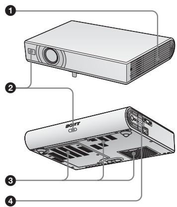
① Ventilation holes (exhaust)
② Remote control detector
③ Ventilation holes (intake)
4 Indicators
Projecting
Connecting the Projector
When you connect the projector, make sure to:
- Turn off all equipment before making any connections.
- Use the proper cables for each connection.
- Insert the cable plugs firmly. When pulling out a cable, be sure to pull it out from the plug, not the cable itself.
Refer also to the instruction manual of the equipment to be connected.
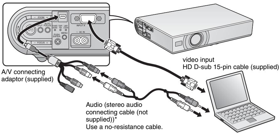
Before making connections
Open the cover to use the AUDIO/VIDEO connector.
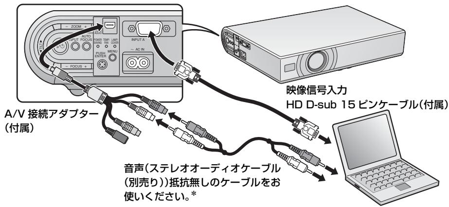
Connecting with a computer
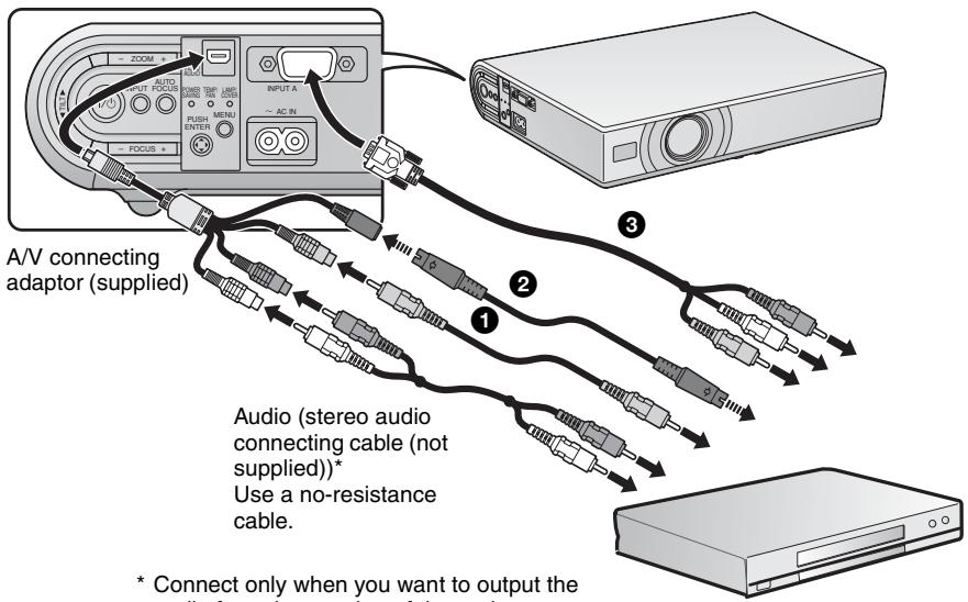
* Connect only when you want to output the audio from the speaker of the projector.
* Connect only when you want to output the audio from the speaker of the projector.
The following three connecting options are available:
① Composite video (phono plug) cable (not supplied)
② S video (Mini DIN 4-pin) cable (not supplied)
③ Component (D-sub 15-pin ↔ 3 × phono plug) cable (not supplied)
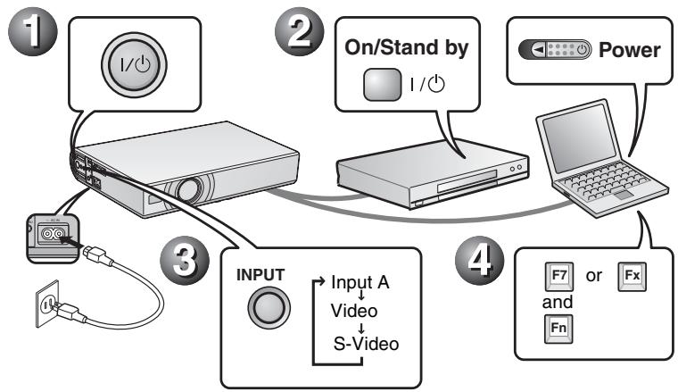
Projecting
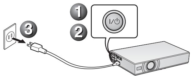
Before connecting the equipment, plug the AC power cord into a wall outlet.
① Press the I/⏻ (on/standby) key.
② Turn on the computer connected to the projector.
③ Press the INPUT key to select the input source.
④ When the computer is connected, set it to output the video signal to only the external monitor.
flowchart
graph TD
    A["1"] --> B["2"]
    B --> C["3"]
    C --> D["4"]
    D --> E["5"]
    E --> F["6"]
    F --> G["7"]
    G --> H["8"]
    H --> I["9"]
    I --> J["Power"]
    K["Input A"] --> L["Video"]
    L --> M["S-Video"]
    N["On/Stand by 1/0"] --> O["Device"]
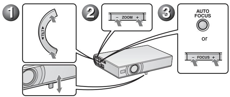
Adjusting the Projector
① Adjust the position of the picture.
② Adjust the size of the picture.
③ Adjust the focus, as required.
flowchart
graph TD
    A["1: Rotation"] --> B["2: Zoom"]
    B --> C["3: AUTO FOCUS or Focus"]
Turning off the Power
① Press the I/ ^1 (on/standby) key.
② When a message appears, press the I/⏻ (on/standby) key again.
③ Unplug the AC power cord from the wall outlet after the fan has stopped running and the ON/STANDBY indicator has lit in red.
Notes
The internal circuitry of the Off & Go function may cause the fan to continue to operate for a short time even after the I/ ^① key is pressed to turn off the power and the ON/STANDBY indicator changes to red.
Replacing the Lamp
The lamp used as a light source is a consumable product. Thus, replace the lamp with a new one in the following cases.
- When the lamp has burnt out or dims
- “Please replace the Lamp.” appears on the screen
- The LAMP/COVER indicator lights up The lamp life varies depending on conditions of use.
Use an LMP-C163 Projector Lamp as the replacement lamp.
Use of any other lamps than the LMP-C163 may cause damage to the projector.
Caution
The lamp remains hot after the projector is turned off with the l/ key. If you touch the lamp, you may burn your finger. When you replace the lamp, wait for at least an hour for the lamp to cool.
Notes
- If the lamp breaks, contact your Customer Information Center.
- Pull out the lamp by holding the handle. If you touch the lamp, you may be burned or injured.
- When removing the lamp, make sure it remains horizontal, then pull straight up. Do not tilt the lamp. If you pull out the lamp while it is tilted and if the lamp breaks, the pieces may scatter, causing injury.
1 Turn off the projector, and disconnect the AC power cord from the AC outlet.
Note
When replacing the lamp after using the projector, wait for at least an hour for the lamp to cool.
2 Place a protective sheet (cloth) beneath the projector. Turn the projector over so you can see its underside.
Note
Be sure that the projector is stable after turning it over.
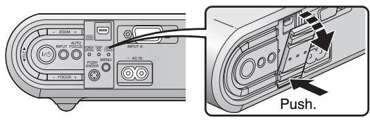
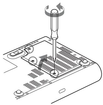
3 Open the lamp cover by loosening the three screws with a Phillips screwdriver.
natural_image
Diagram of a screwdriver inserted into a computer motherboard with no visible text or symbols
Note
For safety reasons, do not loosen any other screws.
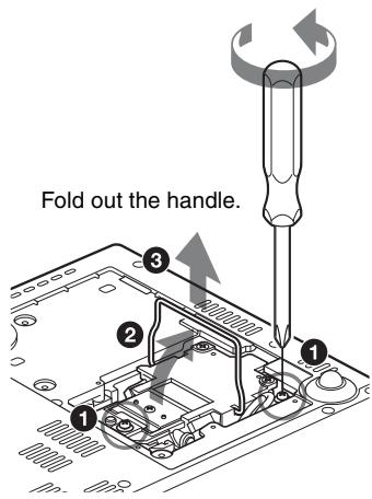
4 Loosen the two screws on the lamp unit with the Phillips screwdriver (1). Fold out the handle (2), then pull out the lamp unit by the handle (3).
5 Insert the new lamp all the way in until it is securely in place (1). Tighten the two screws (3). Fold down the handle to replace it (2).
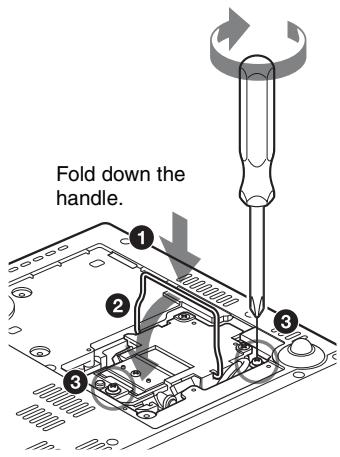
Notes
- Be careful not to touch the glass surface of the lamp.
- The power will not turn on if the lamp is not secured properly.
6 Close the lamp cover and tighten the three screw.
Note
Be sure to attach the lamp cover securely as it was. If not, the projector cannot be turned on.
7 Turn the projector back over.
8 Connect the power cord.
The ON/STANDBY indicator around the I/⏻ key lights in red.
9 Press the following keys on the Remote Commander in the following order for less than five seconds each: RESET, ◀, ▶, ENTER.
Caution
Do not put your hands into the lamp replacement slot, and do not allow any liquid or other objects into the slot to avoid electrical shock or fire.
Disposal of the used lamp
For the customers in the USA
This product contains mercury. Disposal of this product may be regulated if sold in the United States. For disposal or recycling information, please contact your local authorities or the Electronics Industries Alliance (http://www.eiae.org).
Cleaning the Air Filter
The air filter should be cleaned every 500 hours.
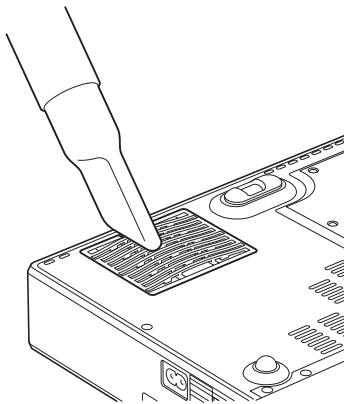
Remove dust from the outside of the ventilation holes with a vacuum cleaner.
500 hours are approximate. This value varies depending on the environment or how the projector is used.
natural_image
Line drawing of a finger pressing down on a computer RAM socket (no text or symbols)
When it becomes difficult to remove the dust from the filter with a vacuum cleaner, remove the air filter and wash it.
1 Turn the power off and unplug the power cord.
2 Place a protective sheet (cloth) beneath the projector and turn the projector over.
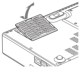
3 Remove the air filter cover.
natural_image
Diagram of a computer monitor with a grid and scroll panel, showing no text or symbols
4 Remove the air filter.
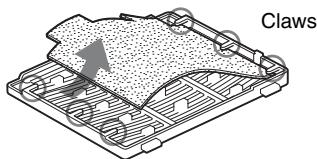
5 Wash the air filter with a mild detergent solution and dry it in a shaded place.
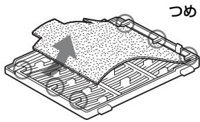
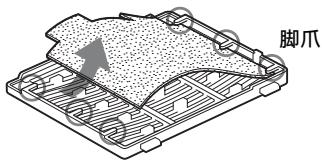
6 Attach the air filter so that it fits into the each claws (6 positions) on the air filter covers and replace the cover.
Notes
- If you neglect to clean the air filter, dust may accumulate, clogging it. As a result, the temperature may rise inside the unit, leading to a possible malfunction or fire.
- If the dust cannot be removed from the air filter, replace the air filter with the supplied new one.
- Be sure to attach the air filter cover firmly; the power can not be turned on if it is not closed securely.
Troubleshooting
If the projector appears to be operating erratically, try to diagnose and correct the problem using the following instructions. If the problem persists, consult with qualified Sony personnel. For details on the symptoms, see the Operating Instructions contained in the CD-ROM.
Power/Picture
| Symptom | Cause and Remedy |
| The power is not turned on. | The power has been turned off and on with the I/⏻ key at a short interval.Wait for about 45 seconds before turning on the power.The lamp cover is not secured.Close the lamp cover securely.The air filter cover is detached.Attach the air filter cover securely. |
| The powered tilt adjuster does not close. | The AC power cord was unplugged with the power of the projector turned on.Connect the power cord to the AC outlet again, turn on the power of the projector, then turn it off. |
| No picture. | A cable is disconnected or the connections are wrong.Check that the proper connections have been made.The connections are wrong.This projector is compatible with DDC2B (Digital Data Channel 2B). If your computer is compatible with DDC, turn the projector on according to the following procedures.Connect the projector to the computer.Turn the projector on.Start the computer.Input selection is incorrect.Select the input source correctly using the INPUT key.The computer signal is not set to output to an external monitor or set to output both to an external monitor and a LCD monitor of a computer.Set the computer signal to output only to an external monitor.Depending on the type of your computer, for example a notebook, or an all-in-one LCD type, you may have to switch the computer to output to the projector by pressing certain keys or by changing your computer's settings.For details, refer to the computer's operating instructions supplied with your computer. |
| The picture is noisy. | Noise may appear on the background depending on the combination of the number of dots input from the connector and the numbers of pixels on the LCD panel.Change the desktop pattern on the connected computer. |
| The picture from the INPUT A connector is colored strangely. | The setting of “Input-A Signal Sel.” on the Setup menu is incorrect.Select “Auto”, “Computer,” “Video GBR” or “Component” correctly according to the input signal. |
| The picture is not clear. | The picture is out of focus. Adjust the focus.Condensation has accumulated on the lens. Leave the projector for about two hours with the power on. |
| The image extends beyond the screen. | The APA key has been pressed even though there are black edges around the image. Display the full image on the screen and press the APA key. Adjust “Shift” on the Signal menu properly. |
| The picture flickers. | “Dot Phase” on the Signal menu has not been adjusted properly. Adjust “Dot Phase” on the Signal menu properly. |
Indicators
| Indicators | Status and Remedy |
| POWER SAVING | Lights up when the projector is in power saving mode. |
| TEMP/FAN | Lights up when temperature inside the projector becomes unusually high. Check to see if anything is blocking the ventilation holes. |
| Flashes when the fan is broken. Consult with qualified Sony personnel. |
| LAMP/COVER | Lights up when the lamp has reached the end of its life or becomes a high temperature. Wait for 45 seconds to cool down the lamp and turn on the power again, or replace the lamp. If the LAMP/COVER indicator still lights even after you have replaced the lamp, the electrical system may break down.Consult with qualified Sony personnel. |
| Flashes when the lamp cover is not secured firmly. Attach the cover securely. |
| I/↓ indicator | Lights in red when a AC power cord is plugged into a wall outlet.Once in standby mode, you can turn on the projector with the I/↓ key. |
| Lights in green when the power is turned on. |
| Flashes in green for several tens of seconds after the power is turned on. Also, flashes for about 45 seconds after the power is turned off with the I/↓ key. During this time, you will not be able to operate the projector. |
Main Specifications
Projection system
3 LCD panels, 1 lens, projection system
LCD panel VPL-CX21: 0.63-inch XGA panel, approximately 2,360,000 pixels (786,432 pixels × 3)
VPL-CS21: 0.63-inch SVGA panel, approximately 1,440,000 pixels (480,000 pixels × 3)
Lens 1.2 times zoom lens (powered)
f 18.8 to 22.6 mm/F1.6 to 1.94
Lamp 165 W Ultra High Pressure lamp
Projected picture size (measured diagonally)
40 to 300 inches
40 to 150 inches (auto focus operation range)
Light output 2100 ANSI lumen
(When the Lamp Mode is set to "High.")
Throwing distance (When placed on the floor.)
40-inch: 1.2 to 1.4 m
(3.9 to 4.6 feet)
80-inch: 2.3 to 2.8 m
(7.5 to 9.2 feet)
100-inch: 2.9 to 3.6 m
(9.5 to 11.8 feet)
150-inch: 4.4 to 5.4 m
(14.4 to 17.7 feet)
200-inch: 5.9 to 7.2 m
(19.4 to 23.6 feet)
250-inch: 7.3 to 9.0 m
(24 to 29.5 feet)
300-inch: 8.8 to 10.7 m
(28.9 to 35.1 feet)
There may be a slight difference between the actual value and the design value shown above.
Color system NTSC3.58/PAL/SECAM/
NTSC4.43/PAL-M/PAL-N/
PAL60 system, switched
automatically/manually
Acceptable computer signals
fH: 19 to 92 kHz
fV: 48 to 92 Hz
(Maximum input signal resolution:
SXGA+ 1400 × 1050
fV: 60 Hz
Applicable video signals
15 k RGB/Component 50/60 Hz,
Progressive component 50/60
Hz, DTV, Composite video, Y/
C video
Dimensions 273× 52× 210mm(10^3 / 4×
2^1/8 × 8^3/8 inches) (w/h/d)
(without projecting parts)
Mass Approx. 1.9 kg (4 lb 3 oz)
Power requirements
AC 100 to 240 V, 2.2 to 1.0 A, 50/60 Hz
Power consumption
Max. 220 W
in standby: 0.8 W
Supplied accessories
Remote Commander (1)
Lithium battery CR2025 (1)
HD D-sub 15 pin cable (2 m) (1)
(1-791-992-XX)
A/V connecting adaptor (1)
(1-830-658-XX)
Carrying case (1)
AC power cord (1)
Operating Instructions (CD-ROM)
(1)
Quick Reference Manual (1)
Safety Regulations (1)
Security Label (1)
Design and specifications are subject to change without notice.
Optional accessories
Projector Lamp
LMP-C163 (for replacement)
natural_image
Diagram of a screwdriver inserted into a laptop keyboard socket (no text or symbols visible)
Remarque
natural_image
Line drawing of a hand using a screwdriver to press or install a component on a computer chassis (no text or symbols)
natural_image
Diagram of a computer monitor with a grid and scroll, showing no text or symbols
NTSC4.43/PAL-M/PAL-N/
natural_image
Diagram of a screwdriver inserted into a computer motherboard with no visible text or symbols
Nota
natural_image
Line drawing of a hand inserting a screw into a computer RAM socket (no text or symbols)
natural_image
Diagram of a computer monitor with a slide and scroll, showing no text or symbols
natural_image
Diagram of a screwdriver inserted into a computer motherboard with no visible text or symbols
Hinweis
natural_image
Line drawing of a hand inserting a screw into a computer motherboard (no text or symbols)
natural_image
Technical line drawing of a computer monitor with a labeled component (no text or symbols present)
natural_image
Diagram of a Klauen device with a textured surface and circuit board (no text or symbols)
NTSC4.43/PAL-M/PAL-N/
natural_image
Diagram of a screwdriver inserted into a computer motherboard with no visible text or symbols
Nota
natural_image
Line drawing of a screwdriver inserted into a computer drive socket (no text or symbols)
natural_image
Diagram of a computer monitor with a grid and scroll panel, showing no text or symbols
NTSC4.43/PAL-M/PAL-N/
PAL60, commutato
automaticamente/manualmente
更换投影灯
natural_image
Diagram of a screwdriver inserted into a computer motherboard with no visible text or symbols
注
为了安全起见,请勿拧松其它任何螺丝。
natural_image
Line drawing of a hand inserting a screw into a computer motherboard (no text or symbols)
natural_image
Diagram of a computer monitor with a grid and scroll panel, showing no text or symbols
4 拆下空气滤网。
Printed on 70% or more recycled paper using VOC (Volatile Organic Compound)-free vegetable oil based ink.
Lead-free solder is used for soldering.
Halogenated flame retardants are not used in cabinets and in printed wiring boards.
Corrugated cardboard is used for the packaging cushions.
Standby power consumption: 0.8W

