
SS-X500A - Pregnant SONY - Free user manual and instructions
Find the device manual for free SS-X500A SONY in PDF.

| Brand | Sony |
| Model | SS-X500A |
| Product type | 2-way bass reflex speaker |
| Speaker configuration | Woofer × 2 (8 cm, cone) and tweeter × 1 (2.5 cm, dome), magnetic shielding |
| Nominal impedance | 8 ohms |
| Maximum input power | 120 W |
| Characteristic sensitivity level | 88 dB (1 W, 1 m) |
| Effective frequency range | 70 Hz to 20,000 Hz |
| Dimensions (per speaker) | Approximately 159 × 634 × 90 mm (w/h/d) |
| Net weight (per speaker) | Approximately 3.5 kg |
| Supplied accessories | Speaker cord (2, 2.5 m), speaker mounting screws (6), bracket mounting screws (8), speaker cord hook (4), ferrite filter (4), instruction manual (1) |
| Intended use | With PFM-500A1WU/A1WE flat-screen monitor |
| Installation | On stand or wall, with adjustable angle |
| Maintenance | Clean with a soft, dry cloth; do not use volatile solvents |
| Precautions | Do not expose to rain, moisture, extreme temperatures; ensure adequate ventilation |
| Operating conditions | Temperature: 0°C to +35°C; humidity 0% to 90% (no condensation) |
| Storage conditions | Temperature: -10°C to +40°C; humidity 0% to 90% (no condensation) |
| Connection | Screw terminals, observe polarity (red ⊕, black ⊖) |
| Warranty and after-sales service | Consult a Sony representative in case of problems |
Frequently Asked Questions - SS-X500A SONY
User questions about SS-X500A SONY
0 question about this device. Answer the ones you know or ask your own.
Ask a new question about this device
Download the instructions for your Pregnant in PDF format for free! Find your manual SS-X500A - SONY and take your electronic device back in hand. On this page are published all the documents necessary for the use of your device. SS-X500A by SONY.
USER MANUAL SS-X500A SONY
Operating Instructions Page 2
Parts Identification 6
Installing the Speakers .... 7
Installing the Speakers on a Wall ......9
Changing the Speaker Angles ....10
Attaching the Ferrite Filters 11
Connecting to the Monitor 12
Connecting to the Amplifier 14
Specifications 15
Features
The SS-X500A is a two-way bass reflex speaker system which adopts a cone-type woofer and tweeter. This speaker system is designed for use with the PFM-500A1WU/A1WE flat panel monitor. The metal mesh grill has been designed to improve the quality of the sound. You can enjoy the high quality stereo sound.
Operating and storage locations
Avoid operating or storing the product in the following locations.
• Extremely hot or cold places
- In direct sunlight for long periods, or close to heating equipment
- Damp or dusty places
• Where it is exposed to rain
- Locations subject to strong vibration
Care
- Clean the cabinet with a soft, dry cloth. If it is very dirty, use a cloth dampened with a small quantity of neutral detergent, then wipe dry.
- Avoid the use of volatile solvents such as alcohol, benzene, and thinners. They may damage the surface finish, or impair the operation of the shutter adaptor.
Ventilation
Do not wrap the unit in a cloth, etc., during operation. This may cause the internal temperature to rise excessively and the unit to malfunction.
Miscellaneous
- Be careful not to spill water or other liquids on the unit or allow combustible or metallic objects inside the body. If used with foreign objects inside, the unit is liable to fail or cause a fire or an electric shock.
- If the product is transported or shipped, repack it as originally packed at the factory, or in materials equal in quality.
- Avoid driving the speaker system continuously with an input exceeding the maximum input power of this speaker system.
- Before connecting, turn off the amplifier to avoid damaging the speaker system.
- If the +/- connection is incorrect, the bass tones seem to be missing and the position of the instruments becomes obscure.
In the event of any problems with the operation of the unit, contact your Sony service representative.
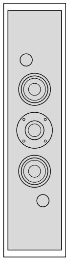
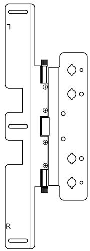
Speaker (2)
natural_image
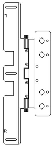
Simple line drawing of a speaker grille with three circular cutouts and two empty circles (no text or symbols)Bracket (2)
natural_image
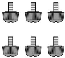
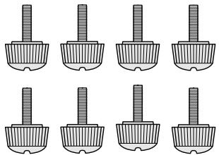
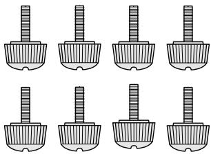
Pure electrical circuit lines without any symbolsSpeaker attachment screw (black, M5×9) (6)
natural_image
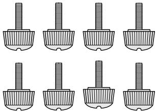
Six identical grayscale images of a mechanical component with threaded ends, arranged in two rows (no text or symbols)Bracket attachment screw (gray, M4×14) (8)
natural_image
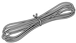
Nine identical mechanical component diagrams arranged in a 3x3 grid, each with a cylindrical shaft (no text or symbols)Speaker cord 2.5 m (2)
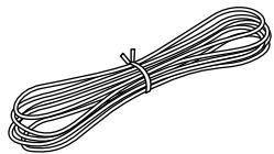
natural_image
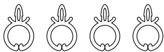
Illustration of a bundle of bundled wires with a tie (no text or symbols)Speaker cord holder (4)
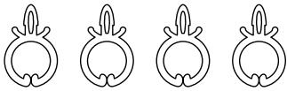
natural_image
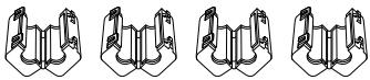
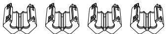
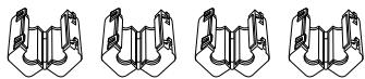
Four identical line drawings of a stylized animal head with leaf-like extensions, arranged horizontally (no text or symbols)Ferrite filter (4)
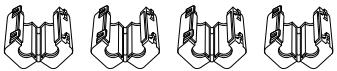
natural_image
Four identical line drawings of a mechanical clamp or bracket component, shown in different angles (no text or symbols)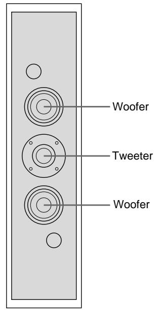
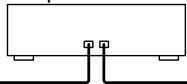
text_image
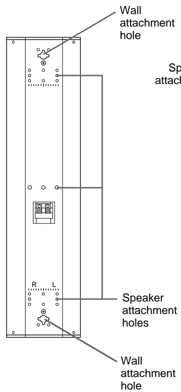
Woofer Tweeter WooferSpeaker Front
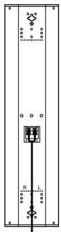
text_image
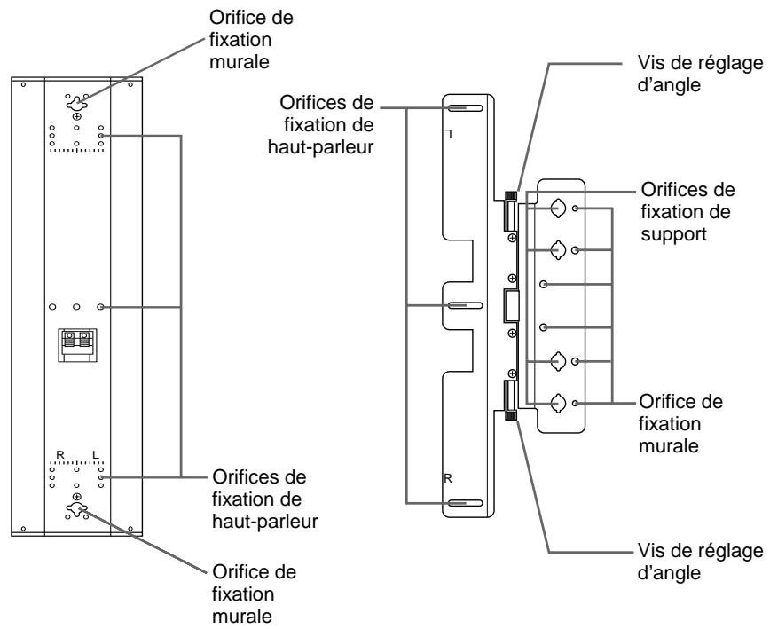
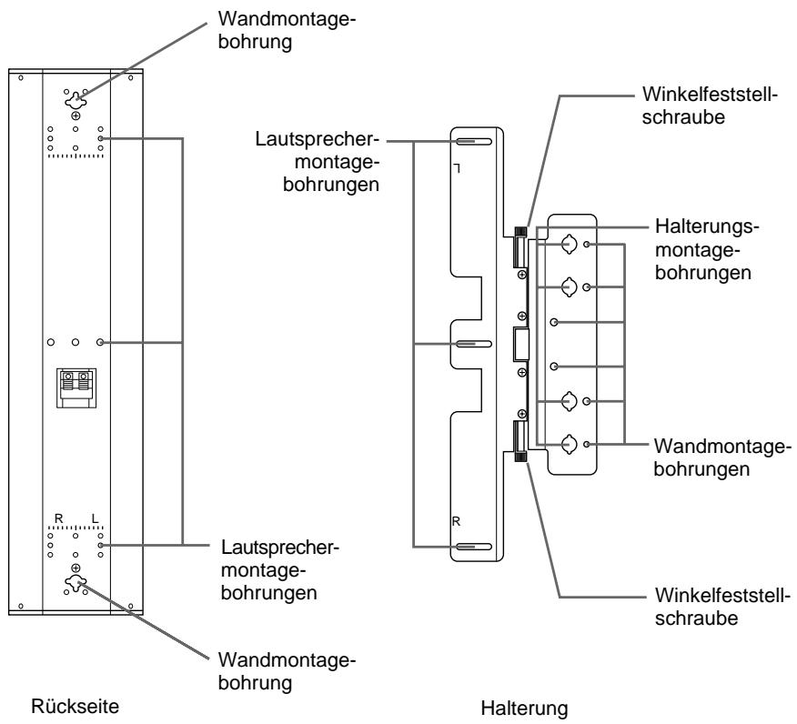
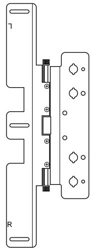
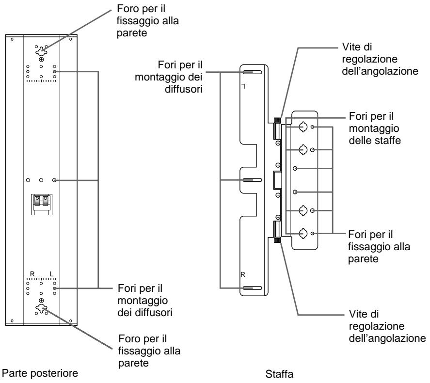
Wall attachment hole Sp attack Speaker attachment holes Wall attachment holeSpeaker Rear
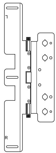
text_image
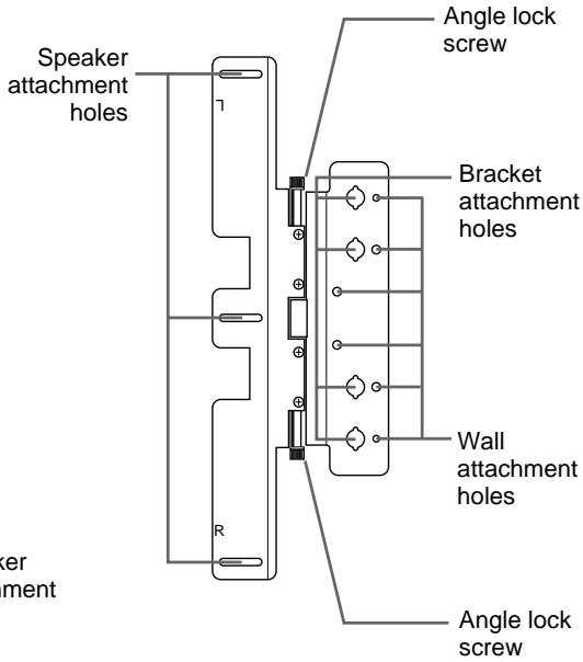
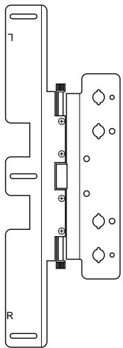
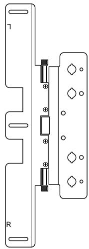
Speaker attachment holes R Angle lock screw Bracket attachment holes Wall attachment holes Angle lock screwBracket
text_image
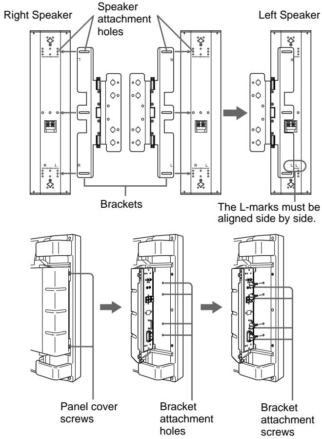
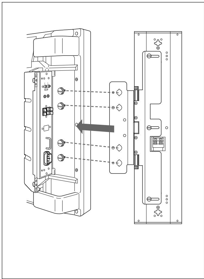
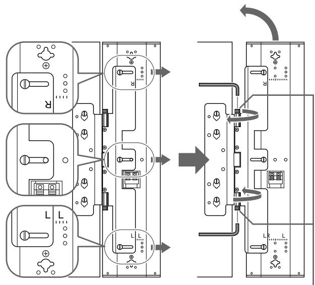
Right Speaker Speaker attachment holes Left Speaker Brackets The L-marks must be aligned side by side. Panel cover screws Bracket attachment holes Bracket attachment screwsInstall the right/left speakers using the brackets as follows:
1 Match the speaker attachment holes on the speaker to the speaker attachment holes on the bracket. Attach the brackets to the speakers with the supplied M5 screws (black, 3 screws each for left and right holes). Assemble the left speaker by matching the L-mark of the speaker to the L-mark of the bracket. (The L-marks must be aligned side by side.) Similarly, you can install the right speaker by matching the R-mark of the speaker to the R-mark of the bracket. (The R-marks must be aligned side by side.)
2 Loosen the panel cover screws (2 each for right and left). Open the panel cover.
There are 4 bracket attachment holes to install the speakers.
3 Insert the supplied M4 screws (gray, 4 screws each for right and left) into the bracket attachment holes and temporarily tighten them.
natural_image
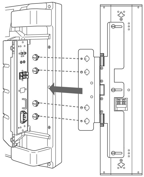
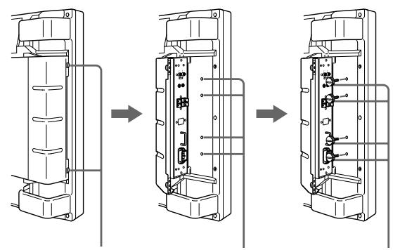
Technical line drawing of a device rear panel with internal components and a directional arrow indicating assembly (no text or symbols present)Monitor
Speaker
4 Hook the bracket attachment holes on the bracket onto the screws temporarily tightened in Step 3. Install the speakers.
5 Tighten the screws completely with a coin and lock the speakers.
6 Connect the speaker to the monitor with the supplied cord.
For more details, see “Connecting to the Monitor” on page 12.
7 Close the panel cover and tighten the panel cover screws (2 screws each for right and left.)
To remove the speakers
Reverse the installation process.
Note
Only use the supplied screws when installing the speakers.
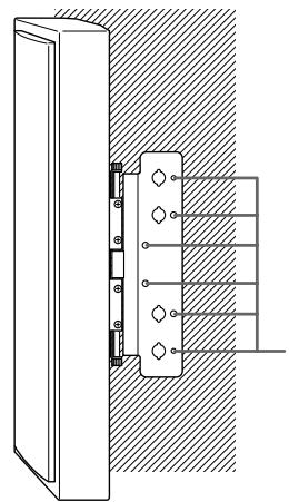
Installing the Speakers on a Wall
When you use a bracket
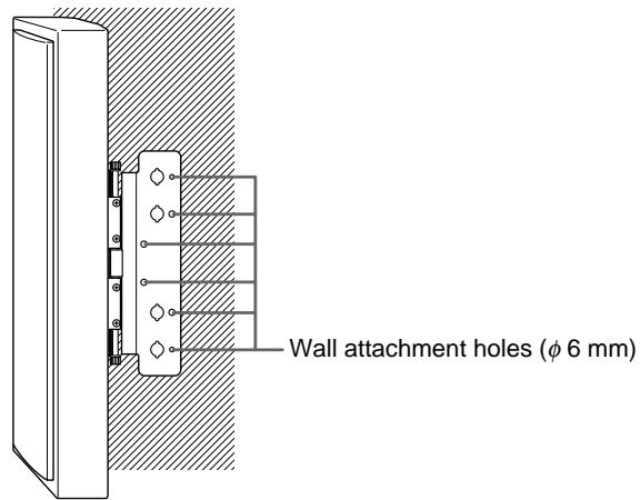
text_image
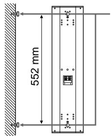
Wall attachment holes (φ 6 mm)When you do not use a bracket
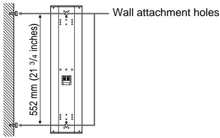
text_image
Wall attachment holes 552 mm (21 3/4 inches)You can install the speakers on a wall using the wall
attachment screw holes of the brackets and speakers.
You can change the speaker angles if you have installed the speakers with the brackets.
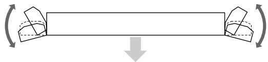
Changing the Speaker Angles
natural_image
Diagram showing a beam under axial compression with two curved supports, no text or symbols presentPFM-500A1WU/A1WE Front
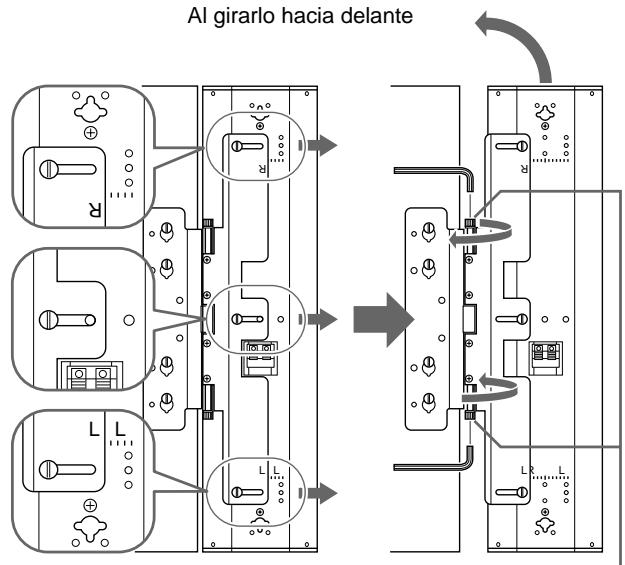
When turning for forward
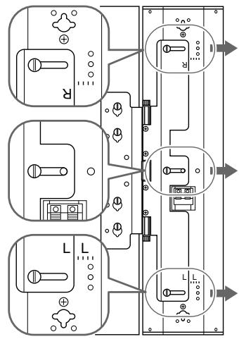
text_image
Electrical wiring diagram showing three-phase power connections with labeled components and connection points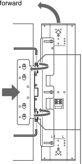
text_image
forward L LAngle lock screw
After installing the speakers on the monitor, you can change the speaker angle.
To move the speakers far forward, follow the steps below:
1 Loosen the M5 screws (black, 3 screws each for right and left that fix the speakers and the brackets). Slide out the speaker.
When fixing the speaker angle, check the scale on the speaker to fix it evenly.
As the speakers slide out, the speakers move more toward the front.
2 Move the speakers to change the speaker angle.
3 To lock the speaker angle, tighten the angle lock screw by hand or with a hexagon wrench.
Note
Do not turn the speaker with excessive force after tightening the angle lock screw.
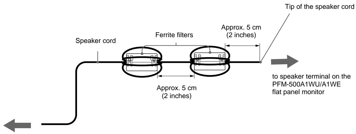
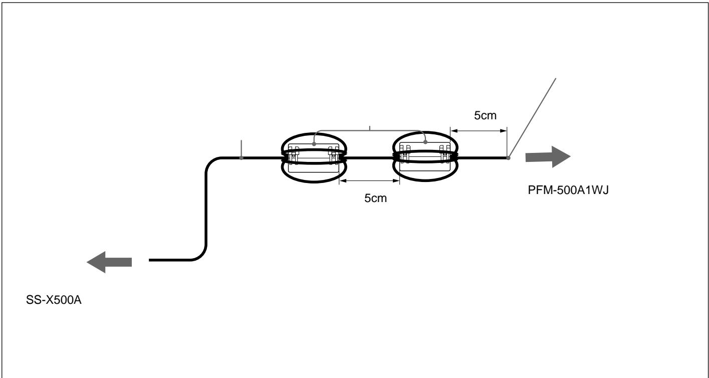
Attaching the Ferrite Filters
Wrap the speaker cable around the supplied filters four times to hold them in place.
text_image
Speaker cord Ferrite filters Approx. 5 cm (2 inches) Approx. 5 cm (2 inches) Tip of the speaker cord to speaker terminal on the PFM-500A1WU/A1WE flat panel monitorto speaker terminal on the SS-X500A speaker system
text_image
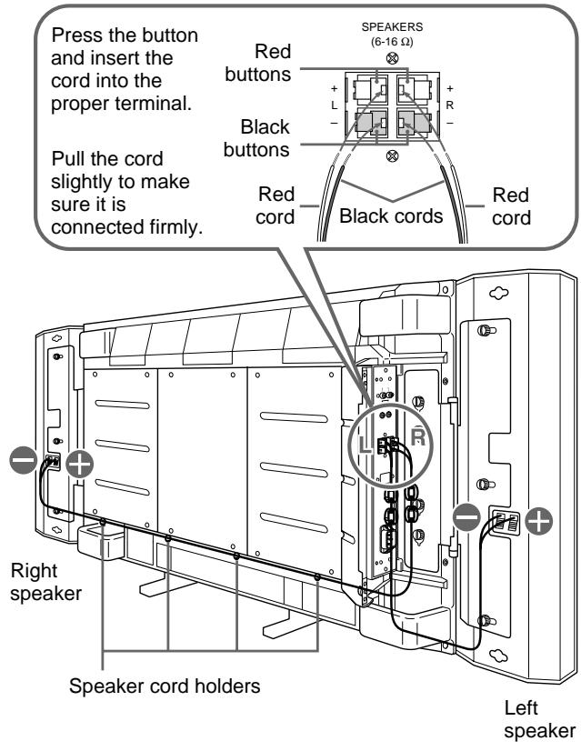
Press the button and insert the cord into the proper terminal. Pull the cord slightly to make sure it is connected firmly. Red buttons SPEAKERS (6-16 Ω) Black buttons Red cord Black cords Red cord Right speaker Speaker cord holders Left speakerBefore connecting the speakers to the monitor, be sure to turn off the monitor's power.
Connect the speakers to the monitor while the panel cover on the monitor is open.
For details on how to install the speakers to the monitor, see “Installing the Speakers” on page 7.
1 Connect the speaker cords to the monitor speaker terminals.
Make sure the R (Right) speaker and L (Left) speaker are connected to the R (Right) terminals and L (Left) terminals on the monitor respectively.
Match the polarity of the speaker terminals with the polarity of the speaker terminals on the monitor, to with the red cord and to with black cord.
2 Connect the speaker cords to the speakers.
Make sure to connect the R (Right) cord to the right speaker and the L (Left) cord to the left speaker.
When you connect the cord to the right speaker, pull out the cord from under the monitor panel cover and lay it under the monitor to the right speaker.
Use the supplied speaker cord holders to tuck the cord.
For details on how to attach the speaker cord holder, see “To install the speaker cord holders” on next page.
Similarly, when you connect the cord to the left speaker, pull out the cord from under the monitor panel cover and lay it under the monitor to the left speaker.
Tuck any excess cord inside the panel cover.
3 Close the right and left panel covers.
text_image
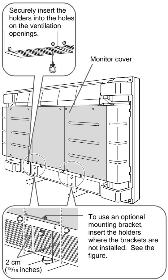
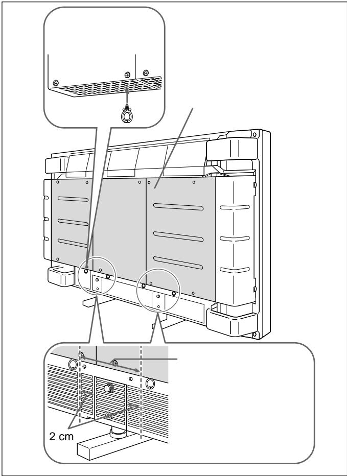
Securely insert the holders into the holes on the ventilation openings. Monitor cover To use an optional mounting bracket, insert the holders where the brackets are not installed. See the figure. 2 cm (13/16 inches)To install the speaker cord holders
As shown in the figure, insert the holders into the holes on the ventilation openings.
Evenly space the holders and insert them under the monitor cover.
If you use an optional mounting bracket, the bracket position and the holder positions should not overlap.
Notes
- Be careful not to short-circuit the speaker terminals according to the wire sticking out of the insulation.
- Connect the speaker cords with correct polarity. Correct -connections of both speaker systems insures proper inphase operation. If the speaker system is out-of-phase, the bass tones seem to be missing and the position of the sound sources become obscure.
- Do not connect the speakers to both an amplifier and a monitor at the same time. Otherwise, the excessive electric current may flow from the amplifier to the monitor via the speaker cord, which may damage the monitor.
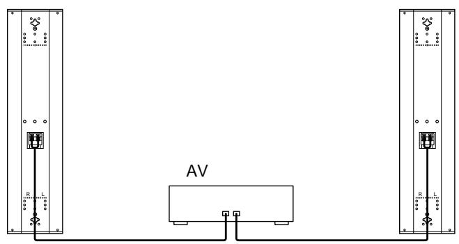
Connecting to the Amplifier
Connect the cord to the speaker terminals of the AV amplifier.
Notes
- The amplifier output must be 120W or less.
- Do not connect the speaker system to the monitor and an amplifier. Doing so may cause a large amount of current to flow into the monitor from the amplifier via the speaker cord, resulting in damage to the monitor.
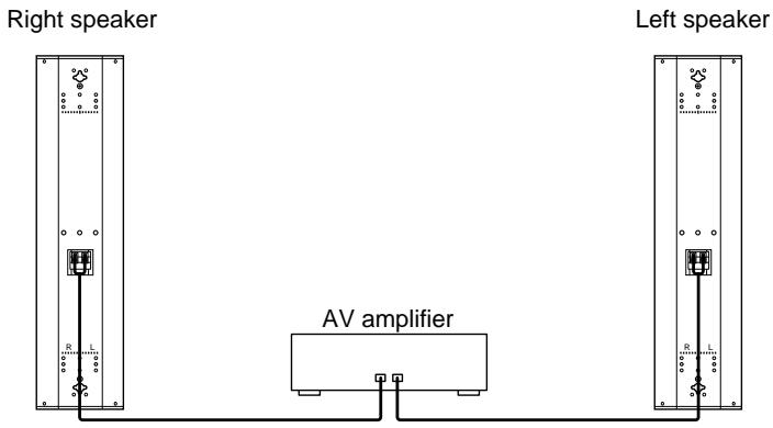
text_image
Right speaker Left speaker AV amplifierSpecifications
Speaker system
Woofer × 2, magnetically shielded
Tweeter × 1, magnetically shielded
Speaker unit 8 cm ( 3^1/4 inches), cone type
2.5 cm (1 inch), dome type
Enclosure type
Bass reflex
Rated impedance
8 ohms
Power handling capacity
Maximum input power: 120 W
Characteristic sensitivity level
88 dB (1 W, 1 m)
Effective frequency range
70 Hz to 20,000 Hz
Operating conditions
Temperature 0°C to +35°C (32°F to 95°F)
Humidity 0% to +90% (no condensation)
Pressure 700 hPa to 1,060 hPa
Transport and storage conditions
Temperature -10^ to +40^ (14°F to
104^)
Humidity 0% to +90% (no condensation)
Pressure 700 hPa to 1,060 hPa
Dimensions Approx. 159 × 634 × 90 mm (6^3/_8 × 25 ×
3 5/8 inches) (w/h/d), including front grille
(net per speaker)
Mass Approx. 3.5 kg (7 lb 11 oz) (net per speaker)
Approx. 1.1 kg (2 lb 7 oz) (net per bracket)
Supplied accessories
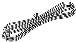
Speaker cord (2, 2.5 m)
Speaker attachment screw (6)
Bracket attachment screw (8)
Speaker cord holder (4)
Ferrite filter (4)
Operating instructions (1)
Design and specifications are subject to change without notice.
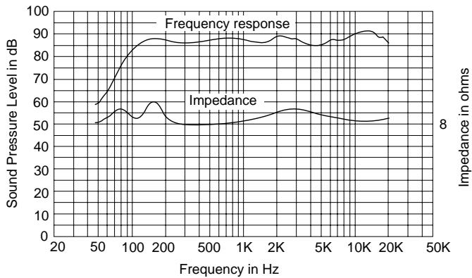
Characteristic curves
line
| Frequency in Hz | Sound Pressure Level in dB | Impedance in ohms | | --------------- | -------------------------- | ------------------ | | 20 | 50 | 8 | | 50 | 60 | 8 | | 100 | 85 | 8 | | 200 | 90 | 8 | | 500 | 88 | 8 | | 1K | 87 | 8 | | 2K | 86 | 8 | | 5K | 85 | 8 | | 10K | 90 | 8 | | 20K | 88 | 8 |AVERTISSEMENT
natural_image
Simple line drawing of a speaker grille with three circular cutouts and two empty circles (no text or symbols)Support (2)
natural_image
Pure electrical circuit lines without any symbolsnatural_image
Six identical mechanical component diagrams arranged in two rows (no text or symbols)Vis de fixation de support (gris, M4×14) (8)
natural_image
Nine identical diagrams of a screw holder with three different shafts, arranged in two rows (no text or symbols)natural_image
Illustration of a bundle of bundled cables (no text or symbols)natural_image
Four identical line drawings of a stylized animal head with leaf-like extensions (no text or symbols)Filtre en ferrite (4)
natural_image
Four identical line drawings of a mechanical component with no text or symbols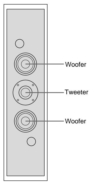
text_image
Woofer Tweeter WooferHaut-parleur avant
natural_image
Technical line drawing of a device rear panel with internal components and a directional arrow indicating assembly (no text or symbols present)natural_image
Diagram showing a beam under axial compression with two curved supports, no text or symbols presentPFM-500A1WU/A1WE Avant
text_image
Electrical wiring diagram showing three-phase power connections with labeled components and directional arrows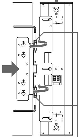
flowchart
graph TD
    A["Switch"] --> B["Component L"]
    B --> C["Component R"]
    C --> D["Output"]
    style A fill:#f9f,stroke:#333
    style B fill:#ccf,stroke:#333
    style C fill:#cfc,stroke:#333
    style D fill:#fcc,stroke:#333
natural_image
Diagram of a speaker grille with three circular speakers and two empty circles (no text or labels)Halterung (2)
natural_image
Pure electrical circuit lines without any symbolsnatural_image
Six identical mechanical component diagrams arranged in two rows (no text or symbols)natural_image
Nine identical mechanical component diagrams showing progressive assembly or mounting (no text or symbols)natural_image
Illustration of a bundle of bundled cables or wires (no text or symbols)natural_image
Four identical line drawings of a stylized animal head with leaf-like extensions, arranged horizontally (no text or symbols)Ferritfilter (4)
natural_image
Four identical line drawings of a mechanical component or bracket, showing internal structure with no text or symbols.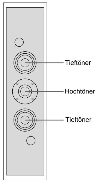
text_image
Tieftöner Hochtöner TieftönerVorderseite
natural_image
Technical line drawing of a device rear panel with internal components and a directional arrow indicating movement (no text or symbols present)natural_image
Diagram showing a beam under load with two curved supports and directional arrows indicating rotation (no text or labels)natural_image
Diagram of a speaker grille with three concentric circles and two circular holes (no text or labels)Soporte (2)
natural_image
Pure electrical connector diagram without any text, numbers, or symbolsnatural_image
Six identical mechanical component diagrams arranged in two rows (no text or symbols)natural_image
Nine identical diagrams of a screw with threaded heads, arranged in two rows (no text or symbols)natural_image
Illustration of a bundle of bundled wires (no text or symbols)natural_image
Four identical line drawings of a stylized animal head with leaf-like extensions (no text or symbols)Filtro de ferrita (4)
natural_image
Four identical line drawings of a mechanical clamp or bracket component, shown in different angles (no text or symbols)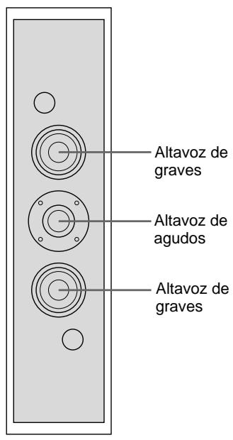
natural_image
Technical line drawing of a device rear panel with internal components and a directional arrow indicating movement (no text or symbols present)Monitor
Altavoz
natural_image
Diagram showing a beam under axial compression with two curved supports, no text or symbols presentParte frontal del PFM-500A1WU/A1WE
natural_image
Diagram of a speaker grille with three concentric circles and two circular holes (no text or labels)Staffa (2)
natural_image
Pure electrical connector diagram without any text, numbers, or symbolsnatural_image
Six identical mechanical component diagrams arranged in two rows (no text or symbols)natural_image
Nine identical mechanical component diagrams arranged in a 3x3 grid, each with a central threaded shaft (no text or symbols)Cavi diffusori 2,5m (2)
natural_image
Illustration of a bundle of bundled cables or wires (no text or symbols)natural_image
Four identical line drawings of a stylized animal head with leaf-like extensions (no text or symbols)natural_image
Four identical line drawings of a mechanical component with no text or symbols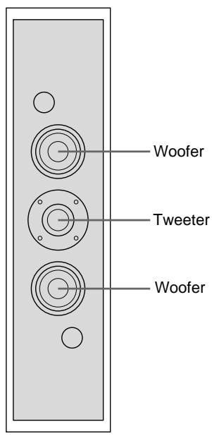
text_image
Woofer Tweeter WooferParte anteriore
natural_image
Technical line drawing of a device rear panel with internal components and a directional arrow indicating assembly (no text or symbols present)Monitor
Diffusore
natural_image
Diagram showing a beam under axial compression with two curved supports, no text or symbols presentParte anteriore PFM-500A1WE
natural_image
Pure electrical circuit lines without any symbolsAmplificatore AV
Diffusore sinistro
natural_image
Pure electrical circuit lines without any symbolsnatural_image
Diagram of a three-tiered speaker or audio device with circular components and two circular holes (no text or symbols)(2)
natural_image
Pure electrical circuit lines without any symbols( M5×9) (6)

natural_image
Six identical mechanical component diagrams arranged in two rows (no text or symbols)( M4×14) (8)
natural_image
Nine identical diagrams of a screw with three parallel grooves, each showing a central shaft (no text or symbols)2.5 m (2)
natural_image
Illustration of a bundle of bundled cables (no text or symbols)(4)
natural_image
Four identical line drawings of a stylized animal head with leaf-like extensions (no text or symbols)(4)
natural_image
Four identical line drawings of a mechanical clamp or bracket component, shown in different angles (no text or symbols)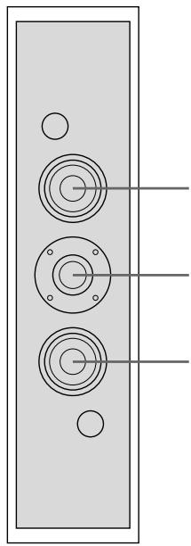
natural_image
Pure diagram of a vertical panel with three circular components and three holes, no text or symbols present.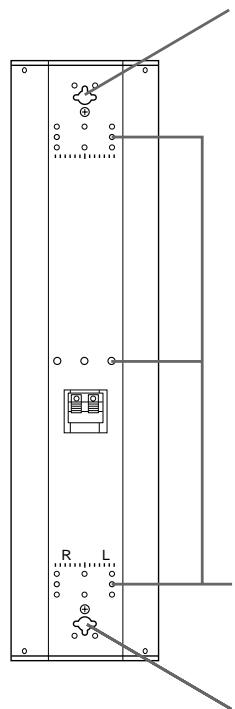
natural_image
Pure electrical circuit lines without any symbols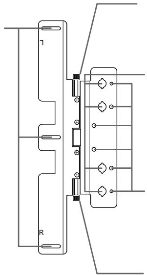
natural_image
Pure electrical circuit lines without any symbols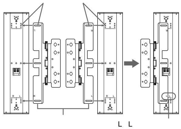
flowchart
graph TD
    subgraph_Module_L["Main Module"]
        A["1"] --> B["R"]
        B --> C["L"]
        C --> D["Output"]
    end

    subgraph_Module_L2["Main Module"]
        E["2"] --> F["R"]
        F --> G["L"]
        G --> H["Output"]

    I["External Components"] --> J["Switches"]
    style Module_L2 fill:#f9f,stroke:#333
    style Module_L2 fill:#ccf,stroke:#333
    style Module_L2 fill:#cfc,stroke:#333
    style Module_L2 fill:#fcc,stroke:#333
natural_image
Three-step diagram showing a mechanical assembly with internal components, no text or symbols present.1
3 )
M5(
L L
R R
2
(2)
4
3
M4(4)
natural_image
Technical line drawing of a mechanical assembly with internal components and alignment arrows (no text or symbols)4
5
3
6
7
)

4
(P.86)
(2
natural_image
Technical line drawing of a door panel with attached electrical connector (no text or symbols)6mm
text_image
552 mm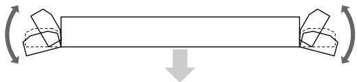
natural_image
Diagram showing a beam with two rotating components and a downward arrow indicating force or direction (no text or symbols)PFM-500A1WJ
flowchart
graph TD
    A["Power Supply"] --> B["Switch Symbol"]
    B --> C["Component Layout"]
    C --> D["Directional Rotation"]
    D --> E["Final Panel"]

    subgraph Power Distribution
        F1["Power Supply"] --> G1["Switch Symbol"]
        F2["Power Supply"] --> G2["Switch Symbol"]
        F3["Power Supply"] --> G3["Switch Symbol"]
    end

    style A fill:#f9f,stroke:#333
    style B fill:#ccf,stroke:#333
    style C fill:#cfc,stroke:#333
    style D fill:#fcc,stroke:#333
    style E fill:#ffc,stroke:#333
1
)
M5(
3
2
3

4
text_image
SS-X500A 5cm 5cm PFM-500A1WJ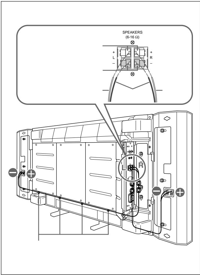
text_image
SPEAKERS (6-16 Ω) + - L R - L R -1
R L
⊕
-
2
1
R
L
3
(81)
text_image
2 cm


AV

• 120W
•
text_image
AV1
× 2
× 1
8cm
25cm
80
EIAJ
120W
88dB 1W 1m
70 20,000Hz
0 +35
0 90%
700 1,060hPa
-10 +40
0 90%
700 1,060hPa
× ×
159× 634× 90mm
35kg 1
1.1kg 1
EIAJ
$$ \begin{array}{cccc} & 2 & 25\mathrm{m} \ & 6 & \ & 8 & \ & & 4 \ & 4 & \ & 1 & \ \end{array} $$
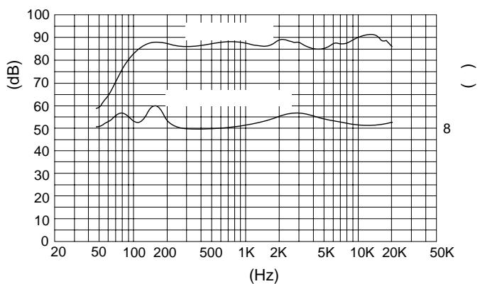
line
| Frequency (Hz) | Value (dB) | | -------------- | ---------- | | 20 | 50 | | 50 | 60 | | 100 | 85 | | 200 | 88 | | 500 | 87 | | 1K | 86 | | 2K | 88 | | 5K | 87 | | 10K | 90 | | 20K | 88 | | 50K | 85 |141-0001
6-7-35
108-0074
4-10-18