
VMC-1 - Uncategorized ROLAND - Free user manual and instructions
Find the device manual for free VMC-1 ROLAND in PDF.


| Product Type | Analog/DV Video Converter/Processor |
| Power Supply | AC adapter included |
| Input Connectors | DV (2x), composite analog, S-video, audio |
| Output Connectors | DV (2x), composite analog (2x), audio |
| Supported Video Formats | NTSC, PAL (selectable via DIP switch) |
| Main Functions | Frame Synchronizer, Time Base Corrector (TBC), 3D Y/C separation, AGC, brightness, color, hue, contrast, audio level adjustments |
| Audio Settings | 48 kHz/16-bit or 32 kHz/12-bit format, locked audio mode, audio mix mode |
| Indicators | Frame synchronization, audio level (green/red) |
| Grounding | Ground terminal |
| Security | Kensington lock |
| Dimensions | Approx. 220 x 45 x 200 mm (W x H x D) (estimated) |
| Weight | Approx. 1.5 kg (estimated) |
| Operating Temperature | 0 to 40 °C (estimated) |
| Maintenance | Clean with a soft dry cloth. Do not use solvents. |
| Included Accessories | AC adapter, instruction manual |
Frequently Asked Questions - VMC-1 ROLAND
User questions about VMC-1 ROLAND
0 question about this device. Answer the ones you know or ask your own.
Ask a new question about this device
Download the instructions for your Uncategorized in PDF format for free! Find your manual VMC-1 - ROLAND and take your electronic device back in hand. On this page are published all the documents necessary for the use of your device. VMC-1 by ROLAND.
USER MANUAL VMC-1 ROLAND
Thank you for purchasing the Edirol VMC-1 Video Optimizer/Media Converter.
Designed to deliver video and audio of a quality that rivals professional equipment, the VMC-1 provides a rich array of image-correction functionality and the capability to convert between analog and DV. It also provides four knobs that let you quickly and easily make adjustments to the image. Analog video such as VHS and eight-millimeter can be cleaned up and saved to DVD-R or other media. You can also use the VMC-1 to export analog video to a notebook computer that has only a DV connector.
Before using this unit, carefully read the sections entitled: "USING THE UNIT SAFELY" and "IMPORTANT NOTES" (p. 2–3, p. 4). These sections provide important information concerning the proper operation of the unit. Additionally, in order to feel assured that you have gained a good grasp of every feature provided by your new unit, Owner's manual should be read in its entirety. The manual should be saved and kept on hand as a convenient reference.
Copyright © 2004 ROLAND CORPORATION
All rights reserved. No part of this publication may be reproduced in any form without the written permission of ROLAND CORPORATION.
USING THE UNIT SAFELY
INSTRUCTIONS FOR THE PREVENTION OF FIRE, ELECTRIC SHOCK, OR INJURY TO PERSONS
About ⚠️ WARNING and ⚠️ CAUTION Notices
| WARNING | Used for instructions intended to alert the user to the risk of death or severe injury should the unit be used improperly. |
| CAUTION | Used for instructions intended to alert the user to the risk of injury or material damage should the unit be used improperly.* Material damage refers to damage or other adverse effects caused with respect to the home and all its furnishings, as well to domestic animals or pets. |
About the Symbols
| The △ symbol alerts the user to important instructions or warnings. The specific meaning of the symbol is determined by the design contained within the triangle. In the case of the symbol at left, it is used for general cautions, warnings, or alerts to danger. | |
| The ⊙ symbol alerts the user to items that must never be carried out (are forbidden). The specific thing that must not be done is indicated by the design contained within the circle. In the case of the symbol at left, it means that the unit must never be disassembled. | |
| The ● symbol alerts the user to things that must be carried out. The specific thing that must be done is indicated by the design contained within the circle. In the case of the symbol at left, it means that the power-cord plug must be unplugged from the outlet. |
ALWAYS OBSERVE THE FOLLOWING
WARNING
- Before using this unit, make sure to read the instructions below, and the Owner's Manual.
- Do not open (or modify in any way) the unit or its AC adaptor.
- Do not attempt to repair the unit, or replace parts within it (except when this manual provides specific instructions directing you to do so). Refer all servicing to your retailer, the nearest Roland Service Center, or an authorized Roland distributor, as listed on the "Information" page.
- Never use or store the unit in places that are:
- Subject to temperature extremes (e.g., direct sunlight in an enclosed vehicle, near a heating duct, on top of heat-generating equipment); or are
- Damp (e.g., baths, washrooms, on wet floors); or are
- Humid; or are
- Exposed to rain; or are
- Dusty; or are
- Subject to high levels of vibration.
- Make sure you always have the unit placed so it is level and sure to remain stable. Never place it on stands that could wobble, or on inclined surfaces.


! WARNING
- Be sure to use only the AC adaptor supplied with the unit. Also, make sure the line voltage at the installation matches the input voltage specified on the AC adaptor's body. Other AC adaptors may use a different polarity, or be designed for a different voltage, so their use could result in damage, malfunction, or electric shock.

- Use only the attached power-supply cord. Also, the supplied power cord must not be used with any other device.

- Do not excessively twist or bend the power cord, nor place heavy objects on it. Doing so can damage the cord, producing severed elements and short circuits. Damaged cords are fire and shock hazards!

- This unit, either alone or in combination with an amplifier and headphones or speakers, may be capable of producing sound levels that could cause permanent hearing loss. Do not operate for a long period of time at a high volume level, or at a level that is uncomfortable. If you experience any hearing loss or ringing in the ears, you should immediately stop using the unit, and consult an audiologist.

- Do not allow any objects (e.g., flammable material, coins, pins); or liquids of any kind (water, soft drinks, etc.) to penetrate the unit.


WARNING
- Immediately turn the power off, remove the AC adaptor from the outlet, and request servicing by your retailer, the nearest Roland Service Center, or an authorized Roland distributor, as listed on the "Information" page when:
- The AC adaptor, the power-supply cord, or the plug has been damaged; or
• If smoke or unusual odor occurs - Objects have fallen into, or liquid has been spilled onto the unit; or
- The unit has been exposed to rain (or otherwise has become wet); or
- The unit does not appear to operate normally or exhibits a marked change in performance.

- In households with small children, an adult should provide supervision until the child is capable of following all the rules essential for the safe operation of the unit.

- Protect the unit from strong impact. (Do not drop it!)

- Do not force the unit's power-supply cord to share an outlet with an unreasonable number of other devices. Be especially careful when using extension cords—the total power used by all devices you have connected to the extension cord's outlet must never exceed the power rating (watts/amperes) for the extension cord. Excessive loads can cause the insulation on the cord to heat up and eventually melt through.

- Before using the unit in a foreign country, consult with your retailer, the nearest Roland Service Center, or an authorized Roland distributor, as listed on the "Information" page.


CAUTION
- The unit and the AC adaptor should be located so their location or position does not interfere with their proper ventilation.

• Always grasp only the plug on the AC adaptor cord when plugging into, or unplugging from, an outlet or this unit.

- At regular intervals, you should unplug the AC adaptor and clean it by using a dry cloth to wipe all dust and other accumulations away from its prongs. Also, disconnect the power plug from the power outlet whenever the unit is to remain unused for an extended period of time. Any accumulation of dust between the power plug and the power outlet can result in poor insulation and lead to fire.

- Try to prevent cords and cables from becoming entangled. Also, all cords and cables should be placed so they are out of the reach of children.

- Never climb on top of, nor place heavy objects on the unit.

- Never handle the AC adaptor or its plugs with wet hands when plugging into, or unplugging from, an outlet or this unit.

- Before moving the unit, disconnect the AC adaptor and all cords coming from external devices.

- Before cleaning the unit, turn off the power and unplug the AC adaptor from the outlet (p. 28).

- Whenever you suspect the possibility of lightning in your area, disconnect the AC adaptor from the outlet.

- Should you remove a screw of the ground terminal, make sure to put them in a safe place out of children's reach, so there is no chance of them being swallowed accidentally.

IMPORTANT NOTES
In addition to the items listed under “USING THE UNIT SAFELY” on page 2–3, please read and observe the following:
Power Supply
- Do not use this unit on the same power circuit with any device that will generate line noise (such as an electric motor or variable lighting system).
- The AC adaptor will begin to generate heat after long hours of consecutive use. This is normal, and is not a cause for concern.
- Before connecting this unit to other devices, turn off the power to all units. This will help prevent malfunctions and/or damage to speakers or other devices.
Placement
- Using the unit near power amplifiers (or other equipment containing large power transformers) may induce hum. To alleviate the problem, change the orientation of this unit; or move it farther away from the source of interference.
- This device may interfere with radio and television reception. Do not use this device in the vicinity of such receivers.
- Noise may be produced if wireless communications devices, such as cell phones, are operated in the vicinity of this unit. Such noise could occur when receiving or initiating a call, or while conversing. Should you experience such problems, you should relocate such wireless devices so they are at a greater distance from this unit, or switch them off.
- Do not expose the unit to direct sunlight, place it near devices that radiate heat, leave it inside an enclosed vehicle, or otherwise subject it to temperature extremes. Excessive heat can deform or discolor the unit.
- When moved from one location to another where the temperature and/or humidity is very different, water droplets (condensation) may form inside the unit. Damage or malfunction may result if you attempt to use the unit in this condition. Therefore, before using the unit, you must allow it to stand for several hours, until the condensation has completely evaporated.
Maintenance
- For everyday cleaning wipe the unit with a soft, dry cloth or one that has been slightly dampened with water. To remove stubborn dirt, use a cloth impregnated with a mild, non-abrasive detergent. Afterwards, be sure to wipe the unit thoroughly with a soft, dry cloth.
- Never use benzine, thinners, alcohol or solvents of any kind, to avoid the possibility of discoloration and/or deformation.
Additional Precautions
- Use a reasonable amount of care when using the unit's buttons, sliders, or other controls; and when using its jacks and connectors. Rough handling can lead to malfunctions.
- When connecting / disconnecting all cables, grasp the connector itself—never pull on the cable. This way you will avoid causing shorts, or damage to the cable's internal elements.
- A small amount of heat will radiate from the unit during normal operation.
- To avoid disturbing your neighbors, try to keep the unit's volume at reasonable levels (especially when it is late at night).
- When you need to transport the unit, package it in the box (including padding) that it came in, if possible. Otherwise, you will need to use equivalent packaging materials.
- This product is compatible with regular NTSC or PAL video signal. In case irregular signal is input, it may obstruct stable operation of this product.
- If using some other make of connection cable, please note the following precautions.
- Some connection cables contain resistors. Do not use cables that incorporate resistors for connecting to this unit. The use of such cables can cause the sound level to be extremely low, or impossible to hear. For information on cable specifications, contact the manufacturer of the cable.
Copyright
- Unauthorized recording, distribution, sale, lending, public performance, broadcasting, or the like, in whole or in part, of a work (musical composition, video, broadcast, public performance, or the like) whose copyright is held by a third party is prohibited by law.
- Do not use this unit for purposes that could infringe on a copyright held by a third party. We assume no responsibility whatsoever with regard to any infringements of third-party copyrights arising through your use of this unit.
USING THE UNIT SAFELY 2
IMPORTANT NOTES......4
Main Features 6
Names of Things and What They Do 8
Front Panel....8
Rear Panel....10
Bottom Panel (DIP Switches)....11
Deutsch
Setup and Connections 28
Turning the Power On/Off....28
Recording Video from a Video Tape to Your DVD Recorder...... 29
Capturing Video from a Video Tape into Your Computer.... 30
Watching Video from Your Computer on a Television 31
Appendix 32
Color Bar Output 32
About Copy-protected Video....32
Troubleshooting....32
Specifications....34
Index 35
Designed for High Quality Video and Audio, with 10-bit Video AD/DA Conversion and 24-bit Audio AD/DA Conversion
Provides a resolution of 10 bits for video decoding and encoding, and 24 bits for audio AD/DA conversion. It also has a Locked Audio function, which prevents video and audio from drifting out of synchronization. (p. 11)
* The Locked Audio function is available only for analog input.
Make Corrections in Real Time While Watching the Image
Differences in camera settings, type, shooting conditions, and shooting technique can produce inconsistencies in the hue and brightness of a video image. Also, analog video that was captured some time ago can often be lacking in vividness of color. When dubbing from analog to analog or from analog to DV or DVD, it is very effective to use the VMC-1's image correction functionality (brightness, intensity, hue, contrast) to minimize such inconsistencies in the image and improve the overall quality. You can use the knobs to make these adjustments in real time while watching the video. (p. 9)
* Available only for analog input.
TBC (Time Base Corrector) for Stabilizing Unstable Images
TBC is a function that cleans up the video image by eliminating the “jitter” (horizontal shaking) caused by inaccuracies in head or tape rotation during analog videotape playback, or due to degradation of the analog video signal. This function is very useful if you are digitizing the video tape library you have collected over the years. You can also apply delay to the audio to correct any timing discrepancies between the video and audio that might be caused by the TBC. You can use a front panel button to switch this function on/off. (p. 8)
* Available only for analog input.
Motion Adaptive 3D Y/C Separator to Reduce Color Smearing and Graininess
This function determines whether the image is moving or stationary, and if stationary, compares the same scan lines of the preceding and following frames to separate the brightness and color signals with high precision. This allows smearing to be reduced, minimizing unwanted noise or blurring. You can use a front panel button to switch this function on/off. (p. 9)
* Available only for composite input in NTSC mode.
Frame Synchronizer Prevents Frame Dropouts and Audio Dropouts
This function corrects inaccuracies in the timing of the video signal. Due to the mechanical characteristics of consumer analog video decks, the preceding or following frame can sometimes be output "out of step." The Frame Synchronizer corrects slight inaccuracies of the synchronization signal to prevent frame dropouts and audio dropouts. (p. 8)
* This will automatically turn on only when you use analog input.
AGC Function Corrects Over-Exposed Whites or Under-Exposed Blacks
The image from a consumer analog video camera or dubbed video tape sometimes does not have the optimal brightness. If such an image is digitized, over-exposed whites or under-exposed blacks may occur. AGC corrects these problems by automatically optimizing the brightness of the analog video. You can use a front panel button to switch this function on/off. (p. 9)
* Available only for analog input.
* Correction is not possible if the input video already has over-exposed whites or under-exposed blacks.
Support for Both NTSC and PAL
* You cannot convert from NTSC to PAL or vice versa.
* 16:9 screen mode is not supported.
Two Sets of Analog Output Jacks Provided
Each set provides an S-video jack and a composite video jack, and they are capable of providing simultaneous output. Analog input -> analog output is also supported, allowing conversion between S-video connector <-> video jack (composite).
Front Panel
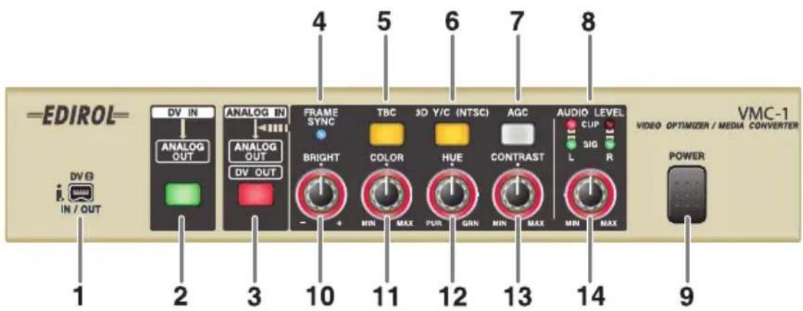
1. DV connector 2 [DV2 IN/OUT]
Connect your DV device or computer here.
* You cannot use this simultaneously with the DV connector 1 on the VMC-1's rear panel (p. 10). If you attempt to use both simultaneously, your DV device may not function correctly.
2. DV input button [DV IN]
Turn this on if you want the video and audio signals from your DV device to be sent from the analog output.
3. Analog input button [ANALOG IN]
Turn this on if you want the video and audio signals from the analog input to be sent from the analog output.
4. Frame synchronizer indicator [FRAME SYNC]
This indicator will light when an analog video signal is input. The frame synchronizer corrects synchronization inaccuracies caused by an unstable video signal, preventing lost frames and audio dropouts.
5. Time base corrector button [TBC]
This corrects the image jitter that often occurs when an analog video deck is playing back. Normally, you should leave this on. If this is on, the video and audio signals will be output with a delay compared to the input signal, in order to allow for this processing to be performed. If this delay is a problem, you can turn this function off.
6. Three-D Y/C separation button [3D Y/C]
This is available only in NTSC mode (p. 11). This will reduce certain problems that may occur when a composite signal is being input, such as fine diagonal black and white stripes producing a rainbow-like effect (cross color) or the appearance of small white and black dots outlined in black (dot interference), and will clean up the signal by reducing color smearing. Normally, you should leave this on. If there is a great deal of movement in the image, this may cause blurring. If so, turn this off. If this is off, 2-D Y/C separation is applied.
* In PAL mode 2-D Y/C separation is always applied, so this button will be disabled.
7. Automatic brightness adjustment button [AGC]
This corrects the over-exposed whites or under-exposed blacks that can occur if the brightness of the image is not appropriate. Normally, you should leave this on.
* Correction is not possible if the input video already has over-exposed whites or under-exposed blacks.
8. Audio level indicator
The green indicator will light when an analog audio signal is input. The red indicator will light if the input level is excessive. Lower the audio input level until the red indicator does not light.
9. Power button [POWER]
10. Brightness knob [BRIGHT]
Turn this knob toward the right to brighten the image, or toward the left to darken the image.
11. Color depth knob [COLOR]
Turn this knob toward the right to deepen the color, or toward the left to lighten the color.
12. Color hue knob [HUE]
Turn this knob toward the right to give the image a more greenish hue, or toward the left to give it a more purple hue.
13. Contrast knob [CONTRAST]
Turn this knob toward the right to make the contrast stronger, or toward the left to decrease it.
14. Audio input level knob [AUDIO LEVEL]
Turn this knob toward the right to increase the audio input level.
* When a DV signal is input, buttons/knobs/indicators 4.-8. and 10.-14. are disabled. These functions apply only to analog input signals.
* When a DV signal is input, the indicators of each button and the illumination around the knobs will go out.
Rear Panel
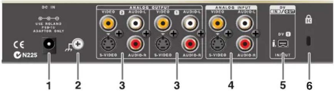
1. AC adaptor jack
Connect the included AC adaptor here.
2. Ground Terminal (p. 28)
3. Analog output jacks 1/2 [ANALOG OUTPUT 1/2]
These are analog output jacks for video and audio. Connect them to your monitor television, DVD recorder, or video deck.
4. Analog input jack [ANALOG INPUT]
This is an analog video/audio jack. Connect it to your VHS or 8mm video deck.
* If video cables are connected to both the S-video input jack and the composite input jack, the S-video input will take priority.
5. DV connector 1 [DV1 IN/OUT]
Connect this to your DV device or computer.
* Do not use this simultaneously with the DV connector 2 located on the front panel of the VMC-1 (p.8). If you use the two simultaneously, your DV device may not work correctly.
6. Security Slot

http://www.kensington.com/
Bottom Panel (DIP Switches)
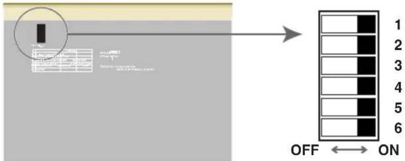
1. Video format setting switch [Video Format]
Specifies the video signal format.
| OFF | NTSC |
| ON PAL |
2. NTSC setup level setting switch [NTSC Setup Level]
Specifies the NTSC setup level.
| OFF 0IRE | |
| ON 7.5IRE |
Select 0IRE in Japan, and select 7.5IRE in North America.
3. Locked Audio mode setting switch [Locked Audio Mode]
Specifies the Locked Audio mode for analog input.
| OFF Locked | |
| ON Unlocked |
4. Audio format setting switch [Audio Format]
Specifies the audio sampling rate and bit depth when using analog input.
| OFF 48kHz | /16bit |
| ON 32kHz | /12bit |
5. Audio mix mode setting switch [Audio Mix Mode]
Specifies whether the sub-channels will be output when you input 32 kHz/12-bit 4-channel audio format via DV.
| OFF Main only |
| ON Mix 50% main + 50% sub |
6. Audio muting time setting switch
Depending on the video editing software you're using, you may experience audio noise at the beginning of playback if this switch is turned ON. In this case, use the OFF setting.
| OFF Normal | |
| ON Short |
* When the VMC-1 is shipped from the factory, DIP switch 6 is turned OFF.
NOTE
Make sure to turn off the power before you change the settings of the DIP switches on the bottom panel.
5. Time-base-corrector Taste [TBC]
| OFF Locked |
| ON Unlocked |
| OFF Main only |
| ON Mix 50% main + 50% sub |
| OFF Locked | |
| ON Unlocked |
| OFF Main only |
| ON Mix 50% main + 50% sub |
| OFF Locked | |
| ON Unlocked |
| OFF Main only |
| ON Mix 50% main + 50% sub |
1. Conector DV 2 [DV2 IN/OUT]
5. Conector DV 1 [DV1 IN/OUT]
| OFF Locked | |
| ON Unlocked |
4. Interruptor de ajuste de formato de audio [Audio Format]
| OFF Main only |
| ON Mix 50% main + 50% sub |
* To prevent malfunction and/or damage to speakers or other devices, always turn down the volume, and turn off the power on all devices before making any connections.
* No video cables come with this product. Please use appropriate video cables for connection with source devices or TV monitor/Projector.
* It is recommended to use composite cable rather than S-video cable where you need to connect devices long distances (unless using S-video amplifiers). If devices are installed closer to the VMC-1, it is recommended to use S-video cables so that you can obtain better image quality.
* When connection cables with resistors are used, the volume level of equipment connected to the inputs (ANALOG INPUT) may be low. If this happens, use connection cables that do not contain resistors.
* Depending on the circumstances of a particular setup, you may experience a discomforting sensation, or perceive that the surface feels gritty to the touch when you touch the metal portions of this device. This is due to an infinitesimal electrical charge, which is absolutely harmless. However, if you are concerned about this, connect the ground terminal with an external ground. When the unit is grounded, a slight hum may occur, depending on the particulars of your installation. If you are unsure of the connection method, contact the nearest Roland Service Center, or an authorized Roland distributor, as listed on the "Information" page.
Unsuitable places for connection
- Water pipes (may result in shock or electrocution)
- Gas pipes (may result in fire or explosion)
- Telephone-line ground or lightning rod (may be dangerous in the event of lightning)
Turning the Power On/Off
Once the connections have been completed (p. 29–31), turn on power to your various devices in the order specified. By turning on devices in the wrong order, you risk causing malfunction and/or damage to speakers and other devices.
Turning the Power On
1 Turn down the volume of audio equipment connected to the VMC-1 to the minimum position.
2 Make sure that the power cable of the AC adaptor is firmly plugged into the VMC-1.
3 Press the POWER switch located on the front panel of the VMC-1.
* This unit is equipped with a protection circuit. A brief interval (a few seconds) after power up is required before the unit will operate normally.
Turning the Power Off
1 Turn down the volume of audio equipment connected to the VMC-1 to the minimum position.
2 Press the POWER switch located on the front panel of the VMC-1.
Recording Video from a Video Tape to Your DVD Recorder
Here's how to record analog video from your VHS or 8 mm deck to your DVD recorder.

* If the composite analog input jack and the S-video jack are both connected, the S-video jack will take priority.
1 Turn the audio input level knob [AUDIO LEVEL] all the way toward the left.
2 Set the brightness [BRIGHT], color depth [COLOR], color hue [HUE], and contrast [CONTRAST] knobs to the center position.
3 Press the analog input button [ANALOG IN].
The button's indicator will light.
4 Play back your video deck.
5 Turn the audio input level knob [AUDIO LEVEL] toward the right, and set it so it's a little before the position at which the red indicator lights.
If the red indicator lights, the sound is distorting.
6 Adjust the brightness [BRIGHT], color depth [COLOR], color hue [CUE], and contrast [CONTRAST] knobs until you are satisfied with the image.
You can switch the time base corrector button [TBC], 3D Y/C separator button [3D Y/C], and automatic brightness adjustment button [AGC] on/off as necessary.
* The 3D Y/C separator button [3D Y/C] applies only to a composite input signal in NTSC mode.
7 Stop your video deck, and rewind the playback location to the beginning.
8 Start recording on your DVD recorder.
9 Play back your video deck.
10 When you have finished recording, stop the DVD recorder and then stop the video deck.
Capturing Video from a Video Tape into Your Computer
Here's how to capture analog video from VHS or 8 mm video into your computer.
* You will need to separately obtain DV recording software.

flowchart
graph LR
    A["VTR"] -->|Analog| B["Analog"]
    B --> C["VMC-1"]
    C -->|DV| D["PC"]
1 Turn the audio input level knob [AUDIO LEVEL] all the way toward the left.
2 Set the brightness [BRIGHT], color depth [COLOR], color hue [HUE], and contrast [CONTRAST] knobs to the center position.
3 Press the analog input button [ANALOG IN]. The button's indicator will light.
4 Play back your video deck.
5 Turn the audio input level knob [AUDIO LEVEL] toward the right, and set it so it's a little before the position at which the red indicator lights. If the red indicator lights, the sound is distorting.
6 Adjust the brightness [BRIGHT], color depth [COLOR], color hue [CUE], and contrast [CONTRAST] knobs until you are satisfied with the image. You can switch the time base corrector button [TBC], 3D Y/C separator button [3D Y/ and automatic brightness adjustment button [AGC] on/off as necessary.
* The 3D Y/C separator button [3D Y/C] applies only to a composite input signal in NTSC mode.
7 Stop your video deck, and rewind the playback location to the beginning.
8 Start recording on your computer. For the procedure, refer to the manual of the software you are using.
9 Play back your video deck.
10 When you have finished recording, stop the video deck.
Watching Video from Your Computer on a Television
Here's how you can use your television to watch video you edited or captured into your computer, or record video from your computer onto a video deck.
* You will need to separately obtain DV playback software.

flowchart
graph LR
    PC["PC"] -->|DV| VMC1["VMC-1"]
    VMC1 -->|Analog| TV["TV"]
1
Press the DV input button [DV IN].
The button's indicator will light.
2
Play back the video on your computer.
For the procedure, refer to the manual of the software you are using.
* You cannot use the VMC-1's image correction functionality or adjust the audio input level knob while using DV input.
Caution when converting to 32 kHz/12-bit/4-channel audio format
32 kHz/12-bit DV audio format is used mainly for post-production with DV video cameras, and allows four-channel recording. The following limitations apply when the VMC-1 is used with this four-channel audio format.
- When converting from analog to DV, only the two main channels will be recorded, regardless of how DIP switch 5 (p. 11) on the bottom panel is set. Nothing will be recorded on the two sub-channels.
- When converting from DV to analog, only the two main channels will be output while the unit remains at the factory settings. If you turn on DIP switch 5 (p. 11) on the bottom panel, the audio will be mixed for output at a proportion of 50% main + 50% sub.
When Converting DV -> Analog Using a DV Connection to Your Computer
- When you play back DV from iMovie, you must first select the desired clip for playback in iMovie, and then switch the VMC-1 to DV IN. If you're using other video editing software, you must first render the video before you perform DV playback.
- You can use DIP switch 6 (located on the bottom panel) to change the length of audio muting that occurs when you begin DV playback.
Color Bar Output
The VMC-1 is able to output color bars from its analog output jack. To output color bars, simultaneously press the DV input button and the analog input button. This is useful when you need to adjust the image on another video device. To return to normal operation, press either of these buttons once again.
* Turning the VMC-1's knobs will not affect the color bar image.
About Copy-protected Video
If copy-protected video is input to the VMC-1, an image with decreased brightness and contrast will be output, and the frame synchronizer indicator will go out.
Troubleshooting
Power Does Not Turn On
Make sure that the included AC adaptor is correctly connected to the VMC-1's AC adaptor jack and is plugged into an AC outlet.
Image and Audio Are Not Output
Make sure that the video cable and audio cable are correctly connected to the input jack and output jack.
When Inputting Analog, Image Is Dark
If copy-protected video is input to the VMC-1, an image with decreased brightness and contrast will be output.
When Inputting Analog, Sound Is Distorted
The audio input level is too high. Turn the audio input level knob so that the red indicator does not light.
When Inputting DV, the Sub Audio Is Not Output
The audio mix mode is set to "main only." Turn ON DIP switch 5 on the bottom panel (p. 11) to select the "50% main + 50% sub" setting.
Image from the Composite Input Jack Not Being Input
If video cables are connected to both the S-video input jack and the composite input jack, the S-video input will take priority. If you are not using the S-video input jack, disconnect the S-video cable.
DV Device Does Not Operate Correctly
Do not use DV connector 1 (back panel) and DV connector 2 (front panel) simultaneously. Your DV device may not operate correctly if you attempt to do so.
Moving the DIP Switches on the VMC-1's Bottom Panel Does Not Change the Setting
If you want to change the DIP switch settings, you must first turn off the power.
Input/output unsuccessful when a DV device or computer is connected to the DV connector
- Check the connections once again.
- Try turning the power off, then on again.
- Try disconnecting and then reconnecting the DV cable.
- Do not use DV connector 1 (rear panel) and DV connector 2 (front panel) at the same time.
- The DV output provided by some DVD recorders may not be compatible with the VMC-1, and cannot be input successfully.
Rapidly moving images are blurred
Turning off the 3D Y/C separator may help.
Over-exposed whites and under-exposed blacks are not corrected
For some images, turning on the automatic brightness compensation (AGC) button may produce virtually no improvement. In such cases, you can adjust the brightness knob and contrast knob. Correction is not possible if the input image already contains over-exposed whites and under-exposed blacks.
Noise is heard in the DV audio output
If you input video from a game device or similar unit, you may hear noise in the DV output audio. If this occurs, changing Locked Audio mode to "Unlocked" may help.
Specifications
VMC-1: Video Optimizer / Media Converter
Video Processing
Supported Video Signals NTSC or PAL (Differing according to regional specifications)
Video Compression Method Native DV format
Video Sampling Rate 13.5 MHz, 4:2:2 (Y:B-Y:R-Y), 8 bits
Video A/D, D/A Conversion 10 bits
Audio Processing
Audio Sampling Rate 48 kHz/16 bits or 32 kHz/12 bits
Audio A/D, D/A Conversion 24 bits
Audio Frequency Response
48 kHz: 20 Hz to 20 kHz (-3/0 dB) 32 kHz: 20 Hz to 15 kHz (-3/0 dB)
Audio Nominal Input Level -10 dBu
Audio Input Impedance 50 k ohms
Audio Non-Clipping Maximum Input Level +7.5 dBu
Audio Nominal Output Level -10 dBu
Audio Output Impedance 1 k ohms
Audio Non-Clipping Maximum Output Level +7.5 dBu
Audio Total Harmonic Distortion 0.05 % or less (1 kHz, Nominal Output Level)
Audio Residual Noise Level -70 dBu (DIN-AUDIO, 1 kHz, Nominal Output Level, IHF-A type)
Audio Channel Separation
-70 dBu (DIN-AUDIO, 1 kHz, Nominal Output Level, IHF-A type)
Input/Output Connectors
Front DV connector (i.LINK) 4-pin connector (comforms to IEEE1394)
Rear DV connector (i.LINK) 4-pin connector (comforms to IEEE1394) S-Video input 4-pin mini DIN type (Y: 1.0 Vp-p, C: 0.286 Vp-p, 75 ohms)
Video input RCA phono type (1.0 Vp-p, 75 ohms)
Audio input (L, R) RCA phono type
S-Video output x 2 4-pin mini DIN type (Y: 1.0 Vp-p, C: 0.286 Vp-p, 75 ohms)
Video output x 2 RCA phono type (1.0 Vp-p, 75 ohms)
Audio output (L, R) x 2 RCA phono type
Power Supply
DC 9 V (AC Adaptor)
Current Draw
800 mA
Dimensions
218.0 (W) x 173.4 (D) x 46.4 (H) mm
8-5/8 (W) x 6-7/8 (D) x 1-7/8 (H) inches
Weight
900 g / 2 lbs (excluding AC Adaptor)
Accessories
AC Adaptor Owner's manual
* 0 dBu = 0.775 Vrms * In the interest of product improvement, the specifications and/or appearance of this unit are subject to change without prior notice.
Numerics
3D Y/C 6,9,12,17,20,25,29-30
4 canales 27
4-channel 11, 15, 19, 31
8 mm 29-30
A
AC adaptor 10,28,32
Adaptador de CA 26
Adaptateur CA 18
AGC 7,9,13,17,21,25,29–30
ANALOG IN 8,12,16,20,24,29–30
Analog Input 12
analog input 8,10,29-30
ANALOG OUTPUT 10, 18, 22, 26
ANALOGER AUSGANG 14
Analoger Eingang 14
Audio Bloccato 23
Audio bloqueado 27
audio dropouts 7
audio format 11, 19, 23, 27, 31
audio input level 9, 17, 29–30, 32
AUDIO LEVEL 9, 13, 17, 21, 25, 29–30
audio mix 11, 19, 23, 32
Audioformat 15
Audio-Inputpegel 13
Audiomix 15
automatic brightness adjustment .. 9, 17, 29–30
brightness 9,29-30,32
brillo 25
C
canale-4 23
COLOR 9,13,17,21,25,29-30
color bar 32
color depth 9,29-30
color hue 9,29-30
composite 29,33
computer 30-31
Conector DV 24, 26
DIP switch 11, 19, 31–33
DIP-Schalter 15
DV connector 8,10,33
DV IN 8,12,16,20,24,31
DV Input 12
DV input 8,31
DV-Anschluss 12, 14
DVD recorder 29
E
HUE 9,13,17,21,25,29–30
|
image correction 6
NTSC Setup Level 11, 15, 19, 23, 27
0
over-exposed whites 7
P
PAL 7
POWER 9,13,17,21,25,28,32
sampling rate 11, 19
Samplingrate 15
sub 11, 15, 19, 27, 31–32
S-video 29,33
time base corrector 6,8,29-30
Time-base-corrector 12
tono del color 25
trasformatore CA 22
U
under-exposed blacks 7
V
Verrouillage 18
VHS 29-30
video deck 29-30
Video Format 11, 15, 19, 23, 27
For the U.K.
IMPORTANT: THE WIRES IN THIS MAINS LEAD ARE COLOURED IN ACCORDANCE WITH THE FOLLOWING CODE.
BLUE: NEUTRAL
BROWN: LIVE
As the colours of the wires in the mains lead of this apparatus may not correspond with the coloured markings identifying the terminals in your plug, proceed as follows:
The wire which is coloured BLUE must be connected to the terminal which is marked with the letter N or coloured BLACK.
The wire which is coloured BROWN must be connected to the terminal which is marked with the letter L or coloured RED.
Under no circumstances must either of the above wires be connected to the earth terminal of a three pin plug.

For EU Countries
This product complies with the requirements of European Directive 89/336/EEC.
For the USA
FEDERAL COMMUNICATIONS COMMISSION RADIO FREQUENCY INTERFERENCE STATEMENT
This equipment has been tested and found to comply with the limits for a Class B digital device, pursuant to Part 15 of the FCC Rules. These limits are designed to provide reasonable protection against harmful interference in a residential installation. This equipment generates, uses, and can radiate radio frequency energy and, if not installed and used in accordance with the instructions, may cause harmful interference to radio communications. However, there is no guarantee that interference will not occur in a particular installation. If this equipment does cause harmful interference to radio or television reception, which can be determined by turning the equipment off and on, the user is encouraged to try to correct the interference by one or more of the following measures:
– Reorient or relocate the receiving antenna.
– Increase the separation between the equipment and receiver.
- Connect the equipment into an outlet on a circuit different from that to which the receiver is connected.
- Consult the dealer or an experienced radio/TV technician for help.
This device complies with Part 15 of the FCC Rules. Operation is subject to the following two conditions:
(1) This device may not cause harmful interference, and
(2) This device must accept any interference received, including interference that may cause undesired operation.
Unauthorized changes or modification to this system can void the users authority to operate this equipment.
This equipment requires shielded interface cables in order to meet FCC class B Limit.
For Canada
NOTICE
This Class B digital apparatus meets all requirements of the Canadian Interference-Causing Equipment Regulations.
AVIS
When you need repair service, call your nearest EDIROL/Roland Service Center or authorized EDIROL/Roland distributor in your country as shown below.
ASIA
CHINA
Roland Shanghai Electronics Co., Ltd. 5F. No.1500 Pingliang Road Shanghai 200090, CHINA TEL: (021) 5580-0800
Roland Shanghai Electronics Co., Ltd. (BEIJING OFFICE) 10F. No.18 3 Section Anhuaxili Chaoyang District Beijing 100011 CHINA TEL: (010) 6426-5050
Roland Shanghai Electronics Co., Ltd. (GUANGZHOU OFFICE) 2/F., No.30 Si You Nan Er Jie Yi Xiang, Wu Yang Xin Cheng, Guangzhou 510600, CHINA TEL: (020) 8736-0428
TAIWAN
ROLAND TAIWAN ENTERPRISE CO., LTD. Room 5, 9fl. No. 112 Chung Shan N.Road Sec.2, Taipei, TAIWAN, R.O.C. TEL: (02) 2561 3339
SINGAPORE/MALAYSIA
Roland Asia Pacific Sdn. Bhd. 45-1, Block C2, Jalan PJU 1/39, Dataran Prima, 47301 Petaling Jaya, Sclangor, MALAYSIA TEL: 3-7805-3263
CENTRAL/LATIN AMERICA
Roland Systems Group U.S. 14830 Desman Road, La Mirada, CA 90638 U.S.A. TEL: 714-521-8000
EUROPE
AUSTRIA/GERMANY/ ITALY/IRELAND/ UNITED KINGDOM
EDIROL (Europe) Ltd. Studio 3.4 114 Power Road London W4 5PY U. K. TEL: (0)20 8747 5949
BELGIUM/FRANCE/ LUXEMBOURG/ SWITZERLAND/ HOLLAND/SPAIN/ PORTUGAL
Roland Iberia, S.L. Paseo Garca Faria, 33-35 08005 Barcelona SPAIN TEL: 93 493 91 00
DENMARK
Roland Scandinavia A/S Nordhavnsvej 7, Postbox 880, DK-2100 Copenhagen DENMARK TEL: 3916 6200
FINLAND
Roland Scandinavia As, Filial Finland Elannontie 5 FIN-01510 Vantaa, FINLAND TEL: (0)9 68 24 020
NORWAY
Roland Scandinavia Avd. Kontor Norge Lillekromsøn 2 Barthals 95
Lilleakerveien 2 Postboks 95 Lilleaker N-0216 Oslo NORWAY TEL: 2273 0074
SWEDEN
Roland Scandinavia A/S SWEDISH SALES OFFICE Danvik Center 28, 2 tr. S-131 30 Nacka SWEDEN TEL: (0)8 702 00 20
HUNGARY
Roland East Europe Ltd. Warehouse Area DEPO Pf.83 H-2046 Torokbalint, HUNGARY TEL: (23) 511011
CZECH REP.
K-AUDIO
Kardasovska 626. CZ-198 00 Praha 9, CZECH REP. TEL: (2) 666 10529
GREECE
STOLLAS S.A. Music Sound Light 155, New National Road Patras 26442, GREECE TEL: 2610 435400
POLAND
MX MUSIC SP.Z.O.O. UL. Gibraltar 4. PL-03664 Warszawa POLAND TEL: (022) 679 44 19
ROMANIA
FBS LINES
Piata Libertatii 1, 535500 Gheorgheni, ROMANIA TEL: (266) 364 609
RUSSIA
MuTek Dorozhnaya ul.3,korp.6 117 545 Moscow, RUSSIA TEL: (095) 981-4967
UKRAINE
TIC-TAC Mira Str. 19/108 P.O. Box 180 295400 Munkachevo, UKRAINE TEL: (03131) 414-40
OCEANIA
Roland Corporation Australia Pty., Ltd. 38 Campbell Avenue Dec Why West, NSW 2099 AUSTRALIA
For Australia Tel: (02) 9982 8266 For New Zealand Tel: (09) 3098 715
NORTH AMERICA
CANADA
Roland Canada Music Ltd. (Head Office) 5480 Parkwood Way, Richmond B. C., V6V 2M4 CANADA TEL.: (604) 270 6626
Roland Canada Music Ltd. (Toronto Office) 170 Admiral Boulevard Mississauga ON L5T 2N6 CANADA TEL: (905) 362 9707
U. S. A.
Roland Systems Group U.S. 14830 Desman Road, La Mirada, CA 90638 U.S.A. TEL: 714-521-8000
As of December 10, 2005 (EDIROL-2)


*03562978-03*
03562978
'05-11-3KS
- Copyright © 2004 ROLAND CORPORATION
- USING THE UNIT SAFELY
- INSTRUCTIONS FOR THE PREVENTION OF FIRE, ELECTRIC SHOCK, OR INJURY TO PERSONS
- ALWAYS OBSERVE THE FOLLOWING
- WARNING
- ! WARNING
- CAUTION
- IMPORTANT NOTES
- Power Supply
- Placement
- Maintenance
- Additional Precautions
- Copyright
- Deutsch
- Designed for High Quality Video and Audio, with 10-bit Video AD/DA Conversion and 24-bit Audio AD/DA Conversion
- Make Corrections in Real Time While Watching the Image
- TBC (Time Base Corrector) for Stabilizing Unstable Images
- Motion Adaptive 3D Y/C Separator to Reduce Color Smearing and Graininess
- Frame Synchronizer Prevents Frame Dropouts and Audio Dropouts
- AGC Function Corrects Over-Exposed Whites or Under-Exposed Blacks
- Support for Both NTSC and PAL
- Two Sets of Analog Output Jacks Provided
- Front Panel
- DV connector 2 [DV2 IN/OUT]
- DV input button [DV IN]
- Analog input button [ANALOG IN]
- Frame synchronizer indicator [FRAME SYNC]
- Time base corrector button [TBC]
- Three-D Y/C separation button [3D Y/C]
- Automatic brightness adjustment button [AGC]
- Audio level indicator
- Power button [POWER]
- Brightness knob [BRIGHT]
- Color depth knob [COLOR]
- Color hue knob [HUE]
- Contrast knob [CONTRAST]
- Audio input level knob [AUDIO LEVEL]
- Rear Panel
- AC adaptor jack
- Ground Terminal (p. 28)
- Analog output jacks 1/2 [ANALOG OUTPUT 1/2]
- Analog input jack [ANALOG INPUT]
- DV connector 1 [DV1 IN/OUT]
- Security Slot
- Bottom Panel (DIP Switches)
- Video format setting switch [Video Format]
- NTSC setup level setting switch [NTSC Setup Level]
- Locked Audio mode setting switch [Locked Audio Mode]
- Audio format setting switch [Audio Format]
- Audio mix mode setting switch [Audio Mix Mode]
- Audio muting time setting switch
- NOTE
- Time-base-corrector Taste [TBC]
- Conector DV 2 [DV2 IN/OUT]
- Conector DV 1 [DV1 IN/OUT]
- Interruptor de ajuste de formato de audio [Audio Format]
- Turning the Power On/Off
- Turning the Power On
- Turning the Power Off
- Recording Video from a Video Tape to Your DVD Recorder
- Capturing Video from a Video Tape into Your Computer
- Watching Video from Your Computer on a Television
- 1
- 2
- Caution when converting to 32 kHz/12-bit/4-channel audio format
- When Converting DV -> Analog Using a DV Connection to Your Computer
- Color Bar Output
- About Copy-protected Video
- Troubleshooting
- Power Does Not Turn On
- Image and Audio Are Not Output
- When Inputting Analog, Image Is Dark
- When Inputting Analog, Sound Is Distorted
- When Inputting DV, the Sub Audio Is Not Output
- Image from the Composite Input Jack Not Being Input
- DV Device Does Not Operate Correctly
- Moving the DIP Switches on the VMC-1's Bottom Panel Does Not Change the Setting
- Input/output unsuccessful when a DV device or computer is connected to the DV connector
- Rapidly moving images are blurred
- Over-exposed whites and under-exposed blacks are not corrected
- Noise is heard in the DV audio output
- Specifications
- VMC-1: Video Optimizer / Media Converter
- Video Processing
- Audio Processing
- Audio Frequency Response
- Audio Channel Separation
- Input/Output Connectors
- Current Draw
- Dimensions
- Weight
- Accessories
- Numerics
- A
- C
- E
- |
- 0
- P
- U
- V
- FEDERAL COMMUNICATIONS COMMISSION RADIO FREQUENCY INTERFERENCE STATEMENT
- NOTICE
- AVIS
- ASIA
- CHINA
- TAIWAN
- SINGAPORE/MALAYSIA
- CENTRAL/LATIN AMERICA
- EUROPE
- AUSTRIA/GERMANY/ ITALY/IRELAND/ UNITED KINGDOM
- BELGIUM/FRANCE/ LUXEMBOURG/ SWITZERLAND/ HOLLAND/SPAIN/ PORTUGAL
- DENMARK
- FINLAND
- NORWAY
- SWEDEN
- HUNGARY
- CZECH REP.
- K-AUDIO
- GREECE
- POLAND
- ROMANIA
- FBS LINES
- RUSSIA
- UKRAINE
- OCEANIA
- NORTH AMERICA
- CANADA
- S. A.
Brand : ROLAND
Model : VMC-1
Category : Uncategorized