MMP12 - Air conditioner Manta - Free user manual and instructions
Find the device manual for free MMP12 Manta in PDF.


| Brand | Manta |
| Model | MMP12 |
| Product Type | Portable Air Conditioner |
| Cooling Capacity | 12000 BTU (approx.) |
| Operating Modes | Cool, Heat, Dry, Fan, Auto |
| Power Supply | 220-240V ~ 50Hz (or 115V ~ 60Hz per nameplate) |
| Fan Speeds | High, Medium, Low |
| Timer | 24-hour on/off timer |
| Remote Control | Included (model R51H/R51H/C, 8m range) |
| Water Tank | Internal tank with full indicator (flashing red) |
| Drain Options | Manual tank drain or continuous drain hose |
| Air Filter | Washable, clean every 2 weeks |
| Safety Features | Auto shut-off when water full, compressor protection (3 min delay) |
| Accessories Included | Exhaust duct, window slider kit, adaptors, drain hose, power cord band |
| Clearance Required | Minimum 30 cm from walls/obstacles |
Frequently Asked Questions - MMP12 Manta
User questions about MMP12 Manta
0 question about this device. Answer the ones you know or ask your own.
Ask a new question about this device
Download the instructions for your Air conditioner in PDF format for free! Find your manual MMP12 - Manta and take your electronic device back in hand. On this page are published all the documents necessary for the use of your device. MMP12 by Manta.
USER MANUAL MMP12 Manta
natural_image
Front view of a white industrial air conditioner unit (no visible text or symbols on body)To ensure proper use of this product please read this User's Manual carefully and keep for future reference.
MM415 Microwave

natural_image
White microwave oven with black control panel and open lid (no visible text or symbols)Pojemność 17 l
Sterowanie manualne
Moc mikrofal 1200W/ Moc grila 900W
natural_image
Exterior view of a stainless steel microwave oven with control panel and display (no visible text or symbols)Obudowa typu INOX
Pojemność 17 I
Operating instruction for the air conditioner 21
Electrical Requirement....22
Operating Instructions 22
Cooling operation 22
Dehumidifying operation 22
Heating operation 22
Fan operation....22
Timer operation 22
Water tank drainage 23
Continuous drainage 23
Installation 23
Window Kit Installation 23
Duct Mount installation....24
Water tank safety feature....25
Air filter 25
Unit Enclosure 25
Unit Idle for long time 26
Remote Controller 26
Performance feature. 26
Names and Functions of indicators on Remote Controller 27
Operating of the Remote Controller 27
Automatic operating 27
COOL,HEAT,and FAN ONLY Operation. 28
Dry operation 28
TIMER Operation....28
Troubleshooting....29
MMP12 Portable Air Conditioner
Návod k obsluze
natural_image
Line drawing of a small air conditioner unit connected to a window (no text or symbols)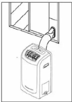
natural_image
Line drawing of a small air conditioner unit with a handle, next to a window frame (no text or symbols)Uwaga!
natural_image
Pure electrical circuit lines without any symbols
natural_image
Diagram showing airflow direction and internal components of a device (no text or symbols)natural_image
Diagram showing two views of a door with directional arrows and a device being inserted (no text or symbols present)natural_image
Technical line drawings of mechanical components including a bolt, funnel, and curved pipe fittings (no text or symbols)natural_image
Diagram of a car air duct system with a hose and panel, showing no text or symbolsStala
natural_image
Diagram of a mechanical device with a curved pipe and diagonal line crossing (no text or symbols)natural_image
Line drawing of a portable air conditioner unit and its internal component (no text or symbols)Filtr powierza.
natural_image
Technical line drawing of a portable air conditioner unit with ventilation slots and a door (no text or symbols)Czyszczenie
natural_image
Simple line drawing of a heating element with cooling fins and cooling unit (no text or symbols)Tryb Cool, Heat, Fan only
Do not dispose this product as unsorted municipal waste. Collection of such waste separately for special treatment is necessary.
It is prohibited to dispose of this appliance in domestic household waste.
For disposal, there are several possibilities:
● The municipality has established collection systems, where electronic waste can be disposed of at least free of charge to the user.
- When buying a new product, the retailer will take back the old product at least free of charge.
● The manufacture will take back the old appliance for disposal at least free of charge to the user.
● As old products contain valuable resources, they can be sold to scrap metal dealers.
Wild disposal of waste in forests and landscapes endangers your health when hazardous substances leak into the ground-water and find their way into the food chain.
To prevent injury to the user or other people and property damage, the following instructions must be followed. Incorrect operation due to ignoring of instructions may cause harm or damage.
Always do this
- Your air conditioner should be used in such a way that it is protected from moisture. e.g. condensation, splashed water, etc. Do not place or store your air conditioner where it can fall or be pulled into water or any other liquid. Unplug immediately.
● Always transport your air conditioner in a vertical position and stand on a stable, level surface during use.
● Turn off the product when not in use.
● Always contact a qualified person to carry out repairs. If the supply cord is damaged it must be repaired by a qualified repairer.
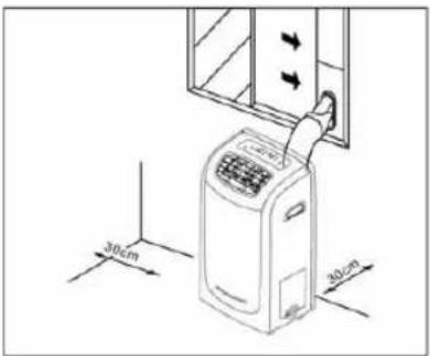
- Keep an air path of at least 30cm all around the unit from walls, furniture and curtains.
- If the air conditioner is knocked over during use, turn off the unit
Never to this
- Do not operate your air conditioner in a wet room such as a bathroom or laundry room.
- Do not touch the unit with wet or damp hands or when barefoot.
-
Do not press the buttons on the control panel with anything other than your fingers.
-
Do not remove any fixed covers. Never use this appliance if it is not working properly, or if it has been dropped or damaged.
● Never use the plug to start and stop the unit.
● Always use the switch on the control panel. - Do not cover or obsturct the inlet or outlet grilles.
- Do not use hazardous chemicals to clean or come into contact with the unit. Do not use the unit in the presence of inflammable substances or vapour such as alcohol, insecticides, petrol, etc.
- Do not allow children to operate the unit unsupervised.
- Do not use this product for functions other than those described in this instruction manual.
Energy Save
● Use the unit in the recommended room size.
- Locate the unit where furniture cannot obstruct the air flow.
- Keep blinds/curtains closed during the sunniest part pf the day.
- Keep the filters clean.
- Keep doors and windows closed to keep cool air in and warm air out.
Akcesoria
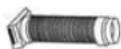
Exhaust Duct x 1

Adaptor A (for permanent duct mounting) (x)

Adaptor B (for temporary duct mounting) x1


Expansion plug x 4

Power Cord Band(for bundling the power cord) x 1

Power Cord Band (for bundling the power cord) x 1

Drain Hose (Connected with water tank) x 1

Window Slider Kit x1
- Check all the accessories are included in the package and please refer to the installation instructions for their usage.
MMP12 Portable Air Conditioner
Names of parts

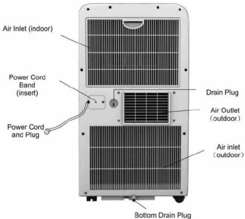
MMP12 Portable Air Conditioner
Control panel

TIMER ON Button: Used to initiate the AUTO ON start time program, and used to adjust Auto-Timer settings.
TIMER OFF Button: Used to initiate the AUTO OFF stop time program, and used to adjust Auto-Timer settings.
TEMP. ADJUST Button:
▲ Used to adjust (forward) temperature settings(1 C/2 F increments).
▼ Used to adjust (backward) temperature settings(1oC/2oF increments).
MODE Button: Selects the appropriate operating mode:
COOL Mode --DRY Mode--FAN Mode--HEAT Mode
Note: "Heat Mode" is for Heating/Cooling Models only.
FAN SPEED Button: Selects High-Medium-Low fan speeds(HI--MED--LO)
FAN Indicator Lights (Green light): Illuminates under the different mode settings:
Fan Options:
- Cooling (3 speeds) HI--MED--LO.
- Heating (3 speeds) HI--MED--LO.
- Dry-Dehumidifying (1 speed) HI.
- Fan (3 speeds) HI--MED--LO.
POWER Button: Power switch On/Off.
Water Full Indicator Light: Flashes red when the water level of the water tank exceeds the maximum set level or if the water tank is not correctly positioned in the cabinet.
Digital Display Window: Shows the setting temperature and Auto-On/Off time. While on DRY and FAN mode, it shows the room temperature.
| Temperature Conversion Chart | |
| °C | 10 11 12 13 14 15 16 17 18 19 20 21 22 23 24 25 26 27 28 29 30 31 32 33 |
| °F | 48 50 52 54 56 58 60 62 64 66 68 70 72 74 76 78 80 82 84 86 88 90 92 94 |
Operating instruction for the air conditioner
Before Starting This Unit
- Select a suitable location, make sure you have easy access to an electrical outlet.
- Install the Flexible Exhaust Hose and the Adjustable Window Slider Kit.

natural_image
Line drawing of a wall-mounted air conditioner unit with cooling fan (no text or symbols)MMP12 Portable Air Conditioner
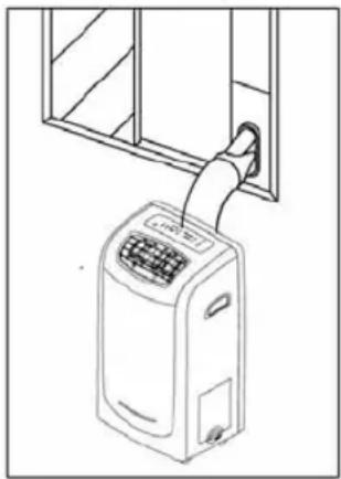
natural_image
Line drawing of a small air conditioner unit attached to a window frame (no text or symbols)NOTE:
Step 2 is required only while using the cooling mode.
- Plug the unit into a 220-240V\~50Hz/ or 115V\~ 60Hz (Refer to the nameplate located on the right side of the unit.) grounded electrical outlet. DO NOT USE A REGULAR EXTENSION
CORD. If it is necessary to use an extension cord with this unit, use an approved air conditioner extension cord only.
- Insert the power cord fixing strap into the hole in the back of the unit, and bundle up the excess cord.
- Make sure the Water tank is correctly positioned inside the cabinet otherwise the unit will not operate.
- Press the POWER button to turn on the unit.
Electrical Requirement
- All wiring must comply with local and national electrical codes and be installed by a qualified electrician. If you have any questions regarding the following instructions, contact a qualified electrician.
- Check available power supply and resolve any wiring problems BEFORE installation and operation of this unit.
- For your safety and protection, this unit is grounded through the power cord plug when plugged into a matching wall outlet. If you are not sure whether the wall outlets in your home are properly grounded, please consult a qualified electrician.
- The manufacturers nameplate is located on the right side panel of the unit and contains electrical and other technical data specific to this unit.
- To avoid the possibility of personal injury, always disconnect the power supply to the unit before installing and/or servicing.
Operating Instructions
Cooling operation
(Operating temperature range: 17^ C - 32^ C/ 62^ F - 92^ F) speed.
Dehumidifying operation
(Operating temperature range: 13°C - 32°C/54°F - 92°F)
- Press the „MODE” button several times until the „DRY” indicator light comes on.
● Under this mode, you cannot select a fan speed or adjust the temperature. The fan motor operates at High speed. - Keep windows and doors closed for the best dehumidifying effect.
- Do not put the duct to window.
CAUTION: During Cooling and dehumidifying modes, if the compressor cycle is interrupted (unplugged, power failure, etc.) and reinstated immediately thereafter, a compressor protection circuit is automatically self affected. The compressor cannot operate during a compressor protection condition. It may take about 3 minutes before the protection circuit self-deactivates. (This is normal)
Heating operation
(Cooling only type without heat feature) (Operating temperature range: 5°C - 30°C/41°F - 88°F)
- Press the „MODE” button several times until the „HEAT” indicator light comes on.
- Press the „TEMP ADJUST” buttons „UP„ or „DOWN„ to select your desired room temperature. The temperature can be set within a range of 1°C - 30°C/62°F - 88°F.
- Press the „FAN SPEED" button to choose the fan speed.
● Do not put the duct to window.
Fan operation
- Press the „MODE” button several times until the „FAN „ indicator light comes on.
- Press the „FAN SPEED" button to choose the fan speed. The temperature cannot be adjusted.
● Do not put the duct to window.
Timer operation
Setting the on timer:
- Press the „TIMER ON" button when the air conditioner is off.
- Continue pressing or keep pressing the „TIMER ON“, button to select the time you need the unit start to
MMP12 Portable Air Conditioner
operate. The time is programmed as :0.5-1.0-1.5-2.0-2.5-3.0-3.5-4.0-4.5-5.0-5.5-6.0-6.5-7.0-7.5-8.0-8.5-9.0-9.5-10-11-12-13-14-15-16-17-18-19-20-21-22-23-24-0.0
● The starting time is adjustable from 0.0 to 24.
Setting the off timer:
- Press the „TIMER OFF" button when the air conditioner is on.
- Continue pressing or keep pressing the „TIMER OFF „ button to select the time you need the unit stop operation. The time is programmed as :0.5-1.0-1.5-2.0-2.5-3.0-3.5-4.0-4.5-5.0-5.5-6.0-6.5-7.0-7.5-8.0-8.5-9.0-9.5-10-11-12-13-14-15-16-17-18-19-20-21-22-23-24-0.0
● The turning off time is adjustable from 0.0 to 24.
Water tank drainage
During Cooling Mode:
● Install the Flexible Exhaust Hose and the Adjustable Window Slider Kit.
- When the water level inside the internal tank reaches a predetermined level, the unit stop operation automatically. The fan motor will continue to operate.
- Carefully remove the water tank from the cabinet and dispose of the water. Replace the water tank back to its original position.
During Dehumidifying Mode:
- Remove the drain plug from the back of the unit and connect the drain hose, then connect the other end of the drain hose to the water tank as depicted in Fig.5. So the condensed water will flow into the internal tank through the drain hose.
- When the water tank is full, just pull it out and dispose of the water.

natural_image
Pure electrical circuit lines without any symbols

Continuous drainage
● This unit also has provisions for a continuous drain option.
● During Cooling and dehumidifying modes, remove the drain plug from the back of the unit, install the continuous drain hose(some models not included), then attach a section garden hose (not included) to the drain hose connector. Place the open end of the hose directly over the drain area in your basement floor.
Note: This drain method will reduce the cooling capacity, in order to maintain the best cooling effect, you had better employ the water tank drainage.


Installation
Window Kit Installation
Your window kit has been designed to fit most standard Vertical and horizontal window applications. However, it may be necessary for you to improvise/modify some aspects of the installation procedures for certain types of window. Please refer to Fig. 7 & Fig. 7a for minimum and maximum window openings.
MMP12 Portable Air Conditioner


Note:
If the window opening is less than the above mentioned minimum length of the window slider kit, cut that one with a hole in it short to fit for the window opening. Do never cut out the hole in window slider kit.
Important
Install the mobile air conditioner in a flat and spacious location where the air outlets will not be covered up. A minimum clearance of 30cm from a wall or other obstacles should be kept. The appliance shall not be used in the laundry. The plug shall accessible after appliance is positioned. Wiring shall be done according to National rules.
Duct Mount installation
natural_image
Technical line drawings of mechanical components including a bolt, conical component, and angled joint (no text or symbols)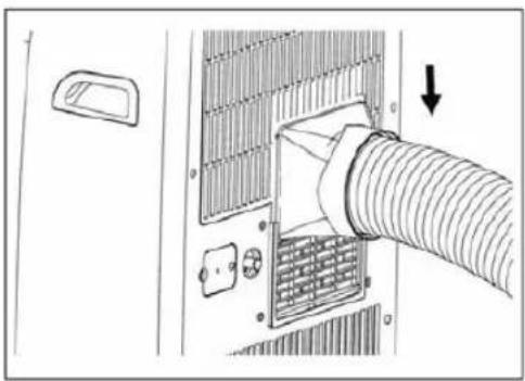
natural_image
Diagram of a car air duct system with a hose and valve, showing no text or symbolsTemporary
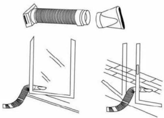
- Attach one end of the duct to the exhaust air outlet of the mobile air condition, push it downwards, be sure to fix thoroughly.
- Attach the other end of the duct to adaptor B.
- Put the end of duct to a nearby window.
Permanent
- Attach one end of the duct to the exhaust air outlet of the mobile air conditioner. According to the arrow direction, push it downwards, be sure to fix thoroughly.
- Install the adaptor A onto the wall by using 4 expansion plugs and screws, be sure to fix thoroughly.
- Attach the other end of the duct to adaptor A.
- Cover the hole using the adaptor cap when not in use.
The duct can be compressed or extended moderately according to the installation requirement, but it is desirable to keep the duct length to a minimum.
MMP12 Portable Air Conditioner

IMPORTANT:
DO NOT OVER BEND THE DUCT

natural_image
Diagram of a mechanical device with a curved pipe and diagonal line crossing (no text or symbols)
natural_image
Line drawing of a portable air conditioner unit and its internal component (no text or symbols)Water tank safety feature
This unit is equipped with a internal water tank. When the water level reaches a predetermined level, the digital display area shows P1 and the water full indicator light flash(red). Carefully remove the water tank from the cabinet and dispose of the water. Replace the water tank back to its original position. The red light will stop flashing and P1 symbol will disappear. The unit will continue operating properly.
Note: When drag the water tank out from the cabinet, please do it slowly and slightly to prevent water splashing. Any time when the water tank is removed/displaced, and /or full of water, the water full indicator will flash red and the digital display area show P1.
IMPORTANT:
- BE SURE TO UNPLUG THE UNIT BEFORE CLEANING OR SERVICING.
2 DO NOT USE GASOLINE, THINNER OR OTHER CHEMICALS TO CLEAN THE UNIT. - DO NOT WASH THE UNIT DIRECTLY UNDER A TAP OR USING A HOSE. THE ELECTRICAL CAUSE DANGER.
- IF THE POWER CORD IS DAMAGED, IT SHOULD BE REPAIRED BY MANUFACTURE OR ITS AGENCY.

Air filter
Clean the air filter at least once every two weeks to prevent inferior fan operation because of dust.
Removal
Pull out the filter cover and remove the air filter from the filter cover.
Cleaning
Wash the air filter by immersing it gently in warm water (about 40^ C/104°F) with a neutral detergent. Rinse the filter and dry it in a shady place.
Mounting
Attach the air filter to the filter cover using the attachment hooks on the inner surface of the cover. Put the filter cover back to the unit.
Unit Enclosure
Use a lint-free cloth soaked with neutral detergent to clean the unit enclosure. Finished by a dry clean cloth.
MMP12 Portable Air Conditioner

natural_image
Diagram of a portable air conditioner unit with ventilation slots and fan (no text or labels)Unit Idle for long time
When you plan to leave this unit unused for a long time, remove the bottom rubber plug from the back hole and attach a section of the continuous drain hose. All the water in the bottom tray would drain outside through the drain hose.
Wrap the cord and bundle it with the band.

natural_image
Diagram of a heating element with cooling fins and cooling unit, showing no text or symbols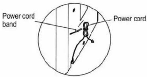
Remote Controller
Performance feature
- Operating Mode: COOL, HEAT, DRY, FAN and AUTO.
- Timer Setting Function in 24 hours.
- Indoor Setting Temperature Range : 17°C \~ 30°C (63°F \~ 86°F)
- LCD (Liquid Crystal Display) of all functions.
- Control function of charactron tube
Model - R51H, R51H/C
Rated Voltage - 3.0V
Lowest Voltage of CPU Emitting Signal - 2.0V
Signal Receiving Range - 8m
Environment - -5°C 60°C(-41°F\~140°F)

flowchart
graph TD
    A["SET TEMPERATURE(°C/°F)"] --> B["AUTO COOL DRY HEAT"]
    B --> C["FAN HIGH MED LOW"]
    C --> D["TEMP"]
    D --> E["MODE"]
    E --> F["FAN SPEED"]
    F --> G["ON/OFF"]
    G --> H["TIMER ON"]
    H --> I["TIMER OFF"]
    I --> J["RESET LOCK"]
    J --> K["③"]
    J --> L["④"]
    J --> M["⑤"]
    J --> N["⑥"]
    J --> O["⑦"]
    J --> P["⑨"]
- TEMP Button: Push the button to decrease the indoor temperature setting.
- MODE Select Button: Each time you push the button, a mode is selected in a sequence that goes from AUTO COOL DRY HEAT and FAN, as the following figure:

- RESET Button: When the RESET button is pushed, all of the current settings are cancelled and the control will return to the initial settings.
- LOCK Button: Push this button to lock in all the current settings. To release settings, push again.
- TIMER ON Button: Press this button to preset the time ON(start to operate). Each press will increase the time ON setting in 30 minutes increments. When the setting time displays 10:00, each press will increase the time ON setting in 60 minutes increments. To cancel the time ON program, simply adjust the time ON to 0:00.
- TIMER OFF Button: Press this button to preset the time OFF (turn off the operation). Each press will increase the time OFF setting in 30 minutes incre-
MMP12 Portable Air Conditioner
ments. When the setting time displays 10:00, each press will increase the time OFF setting in 60 minutes increments. To cancel the time OFF program, simply adjust the time OFF to 0:00
- ON/OFF Button: Push this button to start the unit operation, push the button again to stop the unit operation.
- FAN SPEED Button: This button is used for setting Fan Speed in the sequence that goes from AUTO LOW MED to HIGH, then back to Auto.
- TEMP Button: Push the button to increase the indoor temperature setting.
Names and Functions of indicators on Remote Controller

flowchart
graph TD
    A["1 AUTO COOL DRY HEAT"] --> B["2"]
    B --> C["3"]
    C --> D["4"]
    D --> E["5"]
    E --> F["6"]
    F --> G["FAN HIGH MED LOW"]
    G --> H["h"]
    H --> I["4"]
    I --> J["3"]
    J --> K["4"]
    K --> L["5"]
    L --> M["6"]
- TRANSMISSION Indicator: This indicator lights when remote controller transmits signals to indoor unit.
- MODE Display: Shows the current operation modes-
- AUTO, COOL, DRY, HEAT and FAN. HEAT only available for heat pump model.
- HEAT PUMP ONLY - LOCK display is displayed by pushing the LOCK button. Push the LOCK button again to clear display.
- TIMER Display: This display area shows the settings of TIMER. That is, if only the starting time of operation is set, it will display the
- TIMER ON. If only the turning off time of operation is set, it will display the TIMER OFF. If both operations are set, it will show. TIMER ON OFF which indicates you have chosen to set both the starting time and off time.
- FAN Display: When the FAN button is pushed, this signal indicator lights. Digital Display Area: This area will show the temperature and, if in the TIMER mode, will show the ON and OFF settings of the TIMER.
NOTE:
All items are shown in the Fig.2 for the purpose of clear presentation But during the actual operation only the relative unctional items are shown on the display panel.
Operating of the Remote Controller Install/Replace Batteries
The Remote Controller uses two alkaline dry batteries (R03/Ir03X2).
- To install batteries, slide back the cover of the battery compartment and install the batteries according to the directions (+and -) shown on the Remote Controller.
2 To replace the old batteries, use the same method as mentioned above.
Note:
- When replacing batteries, do not use old batteries or a different type battery. This may cause the remote controller to malfunction.
- If you do not use the remote controller for several weeks remove the batteries. Otherwise battery leakage may damage the remote controller.
● The average battery life under normal use is about 6 months. - Replace the batteries when there is no answering beep from the indoor unit or if the Transmission Indicator light fails to appear.
Automatic operating
When the Air Conditioner is ready for use, switch on the power and the OPERATION indicator lamp on the display panel of the indoor unit starts flashing.
- Use the MODE select button to select AUTO.
- Push the TEMP button to set the desired room temperature. The most comfortable temperature settings are between 21^ C/ 70^ F to 28^ C/ 82^ F
- Push the ON/OFF button to start the air conditioner. The OPERATION lamp on the display panel of the indoor unit lights. The operating mode of AUTO FAN SPEED is automatically set and there are no indicators shown on the display panel of the remote controller.
- Push the ON/OFF button again to stop the unit operation.
Note:
- In the AUTO mode, the air conditioner can logically choose the mode of COOL, FAN, HEAT and DRY by
MMP12 Portable Air Conditioner
sensing the difference between the actual ambient room temperature and the set temperature on the remote controller.
- If the AUTO mode is not comfortable for you, the desired mode can be selected manually.
COOL, HEAT, and FAN ONLY Operation
- If the AUTO mode is not comfortable, you may manually override the settings by using COOL, DRY, HEAT(HEAT PUMP units only), or FAN ONLY modes.
- Push the TEMP button to set the desired room temperature. When in COOLING mode, the most comfortable settings are 2°C/70°F or above. When in HEATING mode, the most comfortable settings are 28°C/82°F or below.
- Push the FAN SPEED to select the FAN mode of AUTO, HIGH, MED or LOW.
- Push the ON/OFF button. The operation lamp lights and the air conditioner starts to operate per your settings. Push the ON/OFF button again to stop this unit operation.
Dry operation
- Push the MODE button to select DRY.
- Push the TEMP button to set the desired temperature from 21^ C/ 70^ F to 28^ C/ 82^ F.
- Push the ON/OFF button. The operation lamp lights and the air conditioner starts to operate in the DRY mode. Push the ON/OFF button again to stop this unit operation.
TIMER Operation
TIMER ON button can set the auto-on time of the unit. TIMER OFF button can set the auto-off time of the unit.
To set the starting time
- Push the TIMER ON button, then the remote controller shows TIMER ON, the last set time for the starting operation and the signal „h” will be shown on the DIGITAL DISPLAY area. You are now ready to reset the time to START the operation.
- Push the TIMER ON button again to set desired unit start time.
- After setting the TIMER ON, there will be a one-half second delay before the remote controller transmits the signal to the air conditioner. Then, after approximately another 2 seconds, the signal "h" disappears and the set temperature will re-appear on the digital display.
To set the stopping time
- After setting the TIMER OFF, there will be a one-half second delay before the remote controller transmits the signal to the air conditioner. Then, after approximately another 2 seconds, the signal "h" disappears and the set temperature will re-appear on the digital display.
2 Push the TIMER OFF button again to set the time you want to stop the operation. - Push the TIMER OFF button and the remote controller will show TIMER OFF, the last set time for the stopping operation and the signal „h” will be shown on the DIGITAL DISPLAY area. You are now ready to reset the time of the STOP operation.
Set the starting & stopping time
- Push the TIMER ON button, the remote controller will show TIMER ON, the last set time for START operation and the signal „h” will be shown on the DIGITAL display area. You are now ready to readjust the TIMER ON to start the operation.
- Push the TIMER ON button again to set the time you want to start the operation.
- Push the TIMER OFF button, the remote controller will show TIMER OFF, the last set time for STOP operation and the signal „h” will be shown on the DIGITAL display area. You are now ready to reset the time to STOP operation.
- Push the TIMER OFF button again to set the time you want to stop the operation.
- After setting the TIMER, there will be a one-half second delay before the remote controller transmits the signal to the Air Conditioner. Then, after approximately another 2 seconds, the set temperature will reappear on the digital display.
Note:
- Please reset the TIMER after cancelling the former time settings.
● The setting time is relative time. That is the time set is based on the delay of the current time.
Warning!
- Be sure there are no barriers between the remote controller and the receiver of indoor unit otherwise the air conditioner will not work.
- Keep the Remote Controller away from all liquids.
● Protect the Remote Controller from high temperatures and exposure to radiation.
- Keep the indoor receiver out of direct sunlight or the Air Conditioner may malfunction.
- Keep controller away from EMI (Electro-Magnetic Interference) supplied by other household appliances.
MMP12 Portable Air Conditioner
Troubleshooting
| TROUBLES POSSIBLE | CAUSES SUGGEST REMEDIES | |
| UNIT DOES NOT START WHEN PRESSING POWER BUTTON | Water full indicator blinks, water tank is full.Room temperature is higher than the set temperature.(Heating mode)Room temperature is lower than the set temperature.(Cooling mode) | Dump the water in the water tank.Reset the temperature.Reset the temperature. |
| NOT COOL ENOUGH | The windows or doors in the room are not closed.There are heat sources inside the room.Exhaust air duct is not connected or blocked.Temperature setting is too high.Air filter is blocked by dust. | Make sure all the windows and doors are closed.Remove the heat sources if possible.Connect the duct and make sure it can function properly.Decrease the set temperature.Clean the air filter. |
| POWER SHUT OFF AT HEATING MODE | The automatic over heat protection function. When the temperature a the air outlet exceed 70°C/158°F,the de vice will st op. | Switch on again after the unit has cool down. |
| NOISY OR VIBRATION | The ground is not level or not flat enough. | Place the unit on a flat, level ground if possible. |
| GURGLING SOUND | The sound comes from the flowing of the refrigerant inside the air-conditioner. | It is normal. |
| COMPRESSOR DOES NOT WORK AND THE DIGITAL DISPLAY AREA SHOWS P2 | The bottom tray is full Remove the bottom drain plug and drain the water outside. | |
MMP12 Portable Air Conditioner
Návod k obsluze
natural_image
Line drawing of a small air conditioner unit with airflow path, no text or symbols present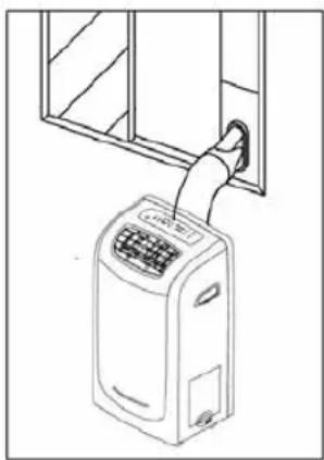
natural_image
Line drawing of a hand inserting a plug into an air conditioner unit (no text or symbols)Pozor!
natural_image
Pure electrical circuit lines without any symbols
natural_image
Diagram showing airflow direction and internal components of a device, including a door with arrows and a connected air conditioner unit (no text or symbols)natural_image
Technical line drawing showing a door opening and a mounted air conditioner unit with airflow arrows (no text or symbols)natural_image
Technical line drawings of mechanical components including a bolt, conical component, and curved pipe fittings (no text or symbols)natural_image
Diagram of a car air duct system with pipe connection and valve (no text or symbols)Na trvalo
natural_image
Diagram showing a device crossed out by a diagonal line, with no visible text or symbols.natural_image
Line drawing of a portable air conditioner unit and its internal component (no text or symbols)Udržba a konservace
Důležité!
natural_image
Technical line drawing of a portable air conditioner unit with ventilation slots and a door (no text or symbols)natural_image
Diagram of a heating element with cooling fins and cooling unit (no text or symbols)natural_image
Line drawing of an air conditioner unit with a cooling fan attached to the top panel (no text or symbols)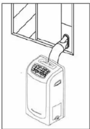
natural_image
Line drawing of a person using a portable air conditioner near a window (no text or symbols)Figyelem:
natural_image
Technical line drawing of a mechanical component with a curved handle and mounting bracket (no text or symbols)
natural_image
Diagram showing a door with arrows indicating direction and a device mounted on a wall (no text or symbols present)natural_image
Technical line drawing showing front and side views of a door and air conditioner unit (no text or symbols)natural_image
Diagram of a portable air conditioner unit with directional arrows indicating airflow or movement (no text or symbols)KIMENETI CSŐ SZERELÉSE
IDEIGLENES
natural_image
Technical line drawings of mechanical components including a threaded bolt, conical tip, and angled pipe (no text or symbols)MMP12 Portable Air Conditioner
natural_image
Diagram of a computer interface showing a cable being inserted into a socket with a handle, no text or symbols presentÁLLANDÓ
natural_image
Pure electrical circuit lines without any symbolsVIZTARTÁLY BIZTONSÁGOS KEZELÉS
natural_image
Line drawing of a portable air conditioner unit and its base case (no text or symbols)natural_image
Black and white photo of a vacuum cleaner with coiled hose (no visible text or symbols)natural_image
Close-up of a white square electronic device with internal components and buttons (no visible text or symbols)- MM415 Microwave
- MMP12 Portable Air Conditioner
- Návod k obsluze
- Uwaga!
- Stala
- Filtr powierza.
- Czyszczenie
- Tryb Cool, Heat, Fan only
- Always do this
- Never to this
- Energy Save
- Akcesoria
- Names of parts
- Control panel
- TEMP. ADJUST Button:
- Fan Options:
- Operating instruction for the air conditioner
- NOTE:
- Electrical Requirement
- Operating Instructions
- Cooling operation
- Dehumidifying operation
- Heating operation
- Fan operation
- Timer operation
- Water tank drainage
- During Cooling Mode:
- During Dehumidifying Mode:
- Continuous drainage
- Installation
- Window Kit Installation
- Important
- Temporary
- Permanent
- Water tank safety feature
- IMPORTANT:
- Air filter
- Removal
- Cleaning
- Mounting
- Unit Enclosure
- Unit Idle for long time
- Remote Controller
- Performance feature
- Operating of the Remote Controller Install/Replace Batteries
- Automatic operating
- COOL, HEAT, and FAN ONLY Operation
- Dry operation
- To set the starting time
- To set the stopping time
- Set the starting & stopping time
- Warning!
- Pozor!
- Na trvalo
- Udržba a konservace
- Důležité!
- Figyelem:
- KIMENETI CSŐ SZERELÉSE
- IDEIGLENES
- ÁLLANDÓ
- VIZTARTÁLY BIZTONSÁGOS KEZELÉS
Brand : Manta
Model : MMP12
Category : Air conditioner