MMS12 - Air conditioner Manta - Free user manual and instructions
Find the device manual for free MMS12 Manta in PDF.


| Product Type | Portable Air Conditioner |
| Model | MMS12 |
| Brand | Manta |
| Cooling Capacity | 12000 BTU/h |
| Energy Efficiency Class | A |
| Power Supply | 220-240V ~ 50Hz |
| Power Consumption (Cooling) | 1100 W |
| Air Flow (Max) | 400 m³/h |
| Noise Level (Low/High) | 45 / 52 dB(A) |
| Dimensions (WxDxH) | 350 x 350 x 700 mm |
| Weight | 25 kg |
| Refrigerant | R290 |
| Operating Modes | Cool, Fan, Dry, Sleep |
| Thermostat Control | Electronic with remote control |
| Timer Function | 1-24 hours |
| Filter Type | Washable pre-filter |
| Filter Cleaning | Every 2 weeks |
| Condensate Drain | Continuous or manual |
| Window Kit Included | Yes (adjustable) |
| Safety Features | Auto restart, overheat protection |
| Spare Parts Availability | Remote control, filters, drain hose |
Frequently Asked Questions - MMS12 Manta
User questions about MMS12 Manta
0 question about this device. Answer the ones you know or ask your own.
Ask a new question about this device
Download the instructions for your Air conditioner in PDF format for free! Find your manual MMS12 - Manta and take your electronic device back in hand. On this page are published all the documents necessary for the use of your device. MMS12 by Manta.
USER MANUAL MMS12 Manta
To ensure proper use of this product please read this User's Manual carefully and keep for future reference.
MM415 Microwave

natural_image
White microwave oven with black screen and control knobs (no visible text or symbols)Pojemność 17 l
Sterowanie manualne
Moc mikrofal 1200W/ Moc grila 900W
natural_image
Exterior view of a stainless steel microwave oven with open door and control panel (no visible text or symbols)Obudowa typu INOX
Pojemność 17 l
Operating condition 31
Description 32
Dosplay 32
Manual operation 32
Optimal operation....33
Adjusting air flow direction 33
How the air conditioner works 34
Automatic operation 34
Sleep operatikon 34
Drying operation.... 35
Maintenance 35
Cleaning the air filter. 35
Maintenance. 36
Operation tips....36
Installation of indoor and outdoor units 37
Indoor unit 37
Outdoor unit 37
Rooftop installation. 38
Accesories 38
Indoor unit installation 39
Connective pipe 40
Indoor unit installation 40
Piping and wrapping. 40
Outdoor installation precaution 40
Settlement of outdoor unit 41
Drain joint installation 41
Refrigerant piping connection 41
Split Air Conditioner
Flaring work 41
Tightening Connection 42
Electrical work 42
Connect the cable to the indoor unit. 43
Connect the cable to the outdoor unit 43
Air Purging 44
Caution in handling the packed valve. 45
When Using the Vacuum Pump 45
Electrical safety check....45
Test running 46
Remote controller 46
Performance Features 46
Operating the Remote Controller 48
Automatic operation 48
COOL/HEAT and FAN Operation. 48
DRY operation 48
TIMER operation 48
Change the TIMER 49
Specification....49
Troubleshooting 50
Návod k obsluze
INSTALACE ELEKTRICKÁ 63
Split Air Conditioner
natural_image
Line drawing of a rectangular air conditioner unit with hands holding arrows indicating side motion (no text or symbols)Panel

natural_image
Technical line drawing of a layered air conditioner unit with a stack of sheets and airflow direction indicated (no text or symbols)natural_image
Simple line drawing of a smiling air conditioner unit with airflow arrows (no text or symbols)Uwaga!

natural_image
Diagram of hands holding a device with arrows indicating movement or force (no text or symbols present)

natural_image
Diagram showing a hand pressing down a textured panel with a black arrow indicating the downward force (no text or symbols present)Split Air Conditioner
natural_image
Hand placing a patterned panel with an upward arrow, no text or symbols presentKonserwacja
Uwaga!
natural_image
Pure technical diagram showing two mechanical or electrical components with no text, numbers, or symbolsnatural_image
Illustration of a hand using a tool to lift a mechanical component (no text or symbols)Klamra kabla
Do not dispose this product as unsorted municipal waste. Collection of such waste separately for special treatment is necessary.
It is prohibited to dispose of this appliance in domestic household waste.
For disposal, there are several possibilities:
● The municipality has established collection systems, where electronic waste can be disposed of at least free of charge to the user.
- When buying a new product, the retailer will take back the old product at least free of charge.
● The manufacture will take back the old appliance for disposal at least free of charge to the user.
- As old products contain valuable resources, they can be sold to scrap metal dealers.
Wild disposal of waste in forests and landscapes endangers your health when hazardous substances leak into the ground-water and find their way into the food chain.
To prevent injury to the user or other people and property damage, the following instructions must be followed. Incorrect operation due to ignoring of instructions may cause harm or damage.
Always do this
- Your air conditioner should be used in such a way that it is protected from moisture. e.g. condensation, splashed water, etc. Do not place or store your air conditioner where it can fall or be pulled into water or any other liquid. Unplug immediately.
● Always transport your air conditioner in a vertical position and stand on a stable, level surface during use.
● Turn off the product when not in use.
● Always contact a qualified person to carry out repairs. If the supply cord is damaged it must be repaired by a qualified repairer. - Keep an air path of at least 30cm all around the unit from walls, furniture and curtains.
- If the air conditioner is knocked over during use, turn off the unit
Never to this
- Do not operate your air conditioner in a wet room such as a bathroom or laundry room.
- Do not touch the unit with wet or damp hands or when barefoot.
-
Do not press the buttons on the control panel with anything other than your fingers.
-
Do not remove any fixed covers. Never use this appliance if it is not working properly, or if it has been dropped or damaged.
● Never use the plug to start and stop the unit.
● Always use the switch on the control panel. - Do not cover or obsturct the inlet or outlet grilles.
- Do not use hazardous chemicals to clean or come into contact with the unit. Do not use the unit in the presence of inflammable substances or vapour such as alcohol, insecticides, petrol, etc.
- Do not allow children to operate the unit unsupervised.
- Do not use this product for functions other than those described in this instruction manual.
Energy Save
● Use the unit in the recommended room size.
- Locate the unit where furniture cannot obstruct the air flow.
- Keep blinds/curtains closed during the sunniest part pf the day.
- Keep the filters clean.
- Keep doors and windows closed to keep cool air in and warm air out.
Operating condition
The air conditioner must be operated within the temperature range indicated below:
| Temp./Mode | Cooling operation | Heating operation | Drying operation |
| Room temperature 17 °C – 32°C | 17°C – 30°C | 17°C – 32°C | |
| Outdoor temperature | 18°C – 43°C | -7°C – 24°C | 18°C – 43°C |
Caution!
- If air conditioner is used outside of the above conditions, certain safety protection features may come into operation and cause the unit to function abnormally.
- Room relative humidity less than 80%. If the air conditioner operates in excess of this figure, the surface of the air conditioner may attract condensation. Please sets the vertical air flow louver to its maximum angle (vertically to the floor), and set HIGH fan mode.
- Optimum performance will be achieved within these operating temperature.
Split Air Conditioner
Description
Indoor unit

Indoor unit
- Front panel
- Air inlet
- Air Iter
- Air outlet
- Horizontal air ow grille
- Vertical air ow louver
- Display panel
- Remote controller signal receiver
- Remote controller
- Manual control button
Outdoor unit
- Connecting pipe, drain hose
- Air inlet (side and rear)
- Air outlet
The operation indicator lights ash rapidly (ve times per second.) when safety protection features come into operation.
Dosplay
Note:
The display panel of the indoor unit would look like one of the following.
For cooling only models (>21000Btu/h unit), 2 indicator light is FAN ONLY.


- AUTO indicator – This indicator illuminates when the air conditioner is in AUTO operation.
- DEFROST indicator (For Cooling & Heating models only) – This indicator illuminates when the air conditioner starts defrosting automatically or when the warm air control feature is activated in heating operation.
- TEMPERATURE indicator – Displays the temperature settings when the air conditioner is operational.
- OPERATION indicator – This indicator ashes after power is on and illuminates when the unit is in operation.
- TIMER indicator – This indicator illuminates when TIMER is set ON/OFF.
Manual operation
Manul operation can be used temporarily in case you can not and the remote controller or its batteries are exhausted.
Split Air Conditioner
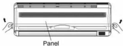

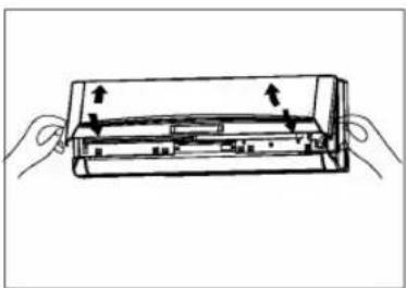
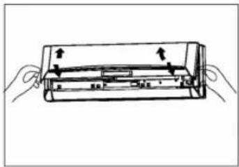
- Open and lift the front panel up to an angle until it remains fixed with a clicking sound.
- One press of the manual control button will lead to the forced AUTO operation.
- Close the panel firmly to its original position.
Caution!
- Once you push the manual button, the operation mode is shifted in an order as: AUTO, COOL, OFF.
● Push the button twice, the unit will operate in forced COOL mode. This is used for testing purposes only.
● Third press will stop the operation and turn off the air conditioner operation.
● To restore the remote controller operation, use the remote controller directly.
Optimal operation
To achieve optimal performance, please note the following:
- Adjust the air flow direction correctly so that it is not directed on people.
- Adjust the temperature to achieve the highest comfort level. Do not adjust the unit to excessive temperature levels.
- Close doors and windows on COOL or HEAT modes, or performance may be reduced.
- Use TIMER ON button on the remote controller to select a time you want to start your air conditioner.
- Do not put any object near air inlet or air outlet, as the efficiency of the air conditioner may be reduced and the air conditioner may stop running.
● Clean the air filter periodically, otherwise cooling or heating performance may be reduced. - Do not operate unit with horizontal louvre in closed position.
Adjusting air flow direction

- Adjust the air flow direction properly otherwise, it might cause discomfort or cause uneven room temperatures.
- Adjust the horizontal louver using the remote controller.
- Adjust the vertical louver manually.
Adjusting the Vertical Air Flow Direction (up - down)
The air conditioner automatically adjusts the vertical air flow direction in accordance with the operating mode.
To set the vertical air flow direction
Perform this function while the unit is in operation.
Keep pressing the AIR DIRECTION button on the remote controller to move the louver to the desired direction.
- Adjust the vertical air flow direction to the desired direction.
- In subsequent operations, the vertical air flow is automatically set in the direction to which you adjusted the louver by pressing the AIR DIRECTION button.

To set the horizontal air flow direction (left - right)
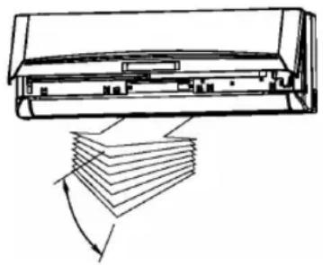
Adjust the vertical louver manually using the lever on the left or right side of the vertical louver arm (Depending on model). Take care not to catch fingers on the fan, horizontal
Split Air Conditioner
louver or to damage vertical louvers. When the air conditioner is in operation and the horizontal louver is in a specific position, move the lever at left (or right, depending on model) end of the air outlet to the desired position.
natural_image
Diagram of a server rack with a stack of books and an arrow indicating compression or lifting (no text or symbols present)To automatically swing the air flow direction (up - down)
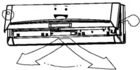
Perform this function while the air conditioner is in operation.
- Press the SWING button on the remote controller.
● To stop the function, press the SWING button again.
Press AIR DIRECTION button to lock louver in desired position.
natural_image
Cartoon illustration of a smiling air conditioner unit with airflow arrows (no text or symbols)Caution!
● The AIR DIRECTION and SWING buttons will be disabled when the air conditioner is not in operation (including when the TIMER ON is set).
- Do not operate the air conditioner for long periods with the air flow direction set downward in cooling or dry mode. Otherwise, condensation may occur on the surface of the horizontal louver causing moisture to drop on to the floor or on furnishings.
- Do not move the horizontal louver manually. Always use the AIR DIRECTION or SWING button. If you move this louver manually, it may malfunction during operation. If the louver malfunctions, stop the airconditioner once and restart it.
- When the air conditioner is started immediately after it was stopped, the horizontal louver might not move for approximately 10 seconds.
- Open angle of the horizontal louver should not be set too small, as COOLING or HEATING performance may be impaired due to too restricted air flow area.
- Do not operate unit with horizontal louver in closed position.
- When the air conditioner is connected to power (initial power), the horizontal louver may generate a sound for 10 seconds, this is a normal operation.
How the air conditioner works
Automatic operation
When you set the air conditioner in AUTO mode, it will automatically select cooling, heating(cooling/heating models only), or fan only operation depending on what temperature you have selected and the room temperature.
The air conditioner will control room temperature automatically round the temperature point set by you.
If the AUTO mode is uncomfortable, you can select desired conditions manually.

Cooling
Sleep operatikon
When you push SLEEP button during cooling, heating (cooling only type without), or AUTO operation, the air conditioner will automatically increase (cooling) or decrease (heating) 1 per hour. The set temperature will be steady 2 hours later.
The fan speed will be automatically controlled.

Heating
Split Air Conditioner
Drying operation
The dry mode will automatically select the drying operation based on the difference between the set temperature and the actual room temperature.
The temperature is regulated while dehumidifying by repeating turning on and off of the cooling operation or fan only. The fan speed is LOW.

Maintenance
Caution!
- Use a dry cloth to wipe the indoor unit and remote controller.
● A cloth dampened with cold water may be used on the indoor unit if it is very dirty.
● The front panel of the indoor unit can be removed and cleaned with water. Then wipe it with a dry cloth. - Do not use a chemically treated cloth or duster to clean the unit.
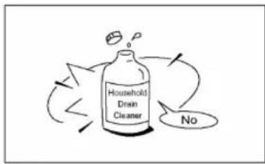
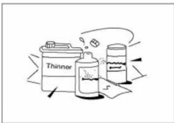
- Do not use benzine, thinner, polishing powder, or similar solvents for cleaning. These may cause the plastic surface to crack or deform.

natural_image
Diagram of a device with hands holding a transparent case, showing internal components and directional arrows (no text or symbols)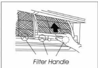
Cleaning the air filter
A clogged air filter reduces the cooling efficiency of this unit. Please clean the filter once every 2 weeks.
- Lift the indoor unit panel up to an angle until it stops with a clicking sound.
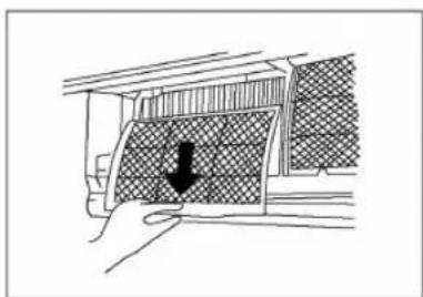
- Take hold of the handle of the air filter and lift it up slightly to take it out from the filter holder, then pull it downwards.
- Remove the AIR FILTER from the indoor unit.
Clean the AIR FILTER once two weeks.
Clean the AIR FILTER with a vacuum cleaner or water, then dry it up in cool place.
natural_image
Diagram showing a hand pressing down a car window with a black arrow indicating the downward motion (no text or symbols present)Split Air Conditioner
-
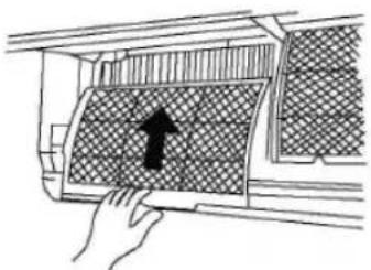
Install the air filter back into position.
-
Insert the upper portion of air filter back into the unit taking care that the left and right edges line up correctly and place filter into position.
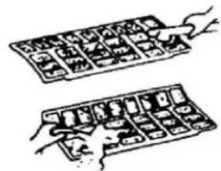
natural_image
Illustration of two hands holding a grid of small objects, possibly food items or containers (no text or symbols visible)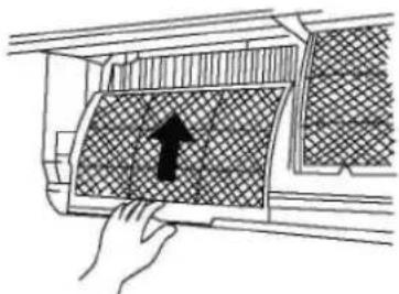
natural_image
Hand placing a patterned object into a window frame with an upward arrow (no text or symbols)Maintenance
Checks before operation
If you plan to idle the unit for a long time, perform the following:
-
Operate the fan for about half a day to dry the inside of the unit.
-
Stop the air conditioner and disconnect power. Remove the batteries from the remote controller.
-
The outdoor unit requires periodic maintenance and cleaning. Do not attempt to do this yourself.
Contact your dealer or servicer.
Check that the wiring is not broken off or disconnected. Check that the air filter is installed.
Check if the air outlet or inlet is blocked after the air conditioner has not been used for a long time.
Caution!
- Do not touch the metal parts of the unit when removing the filter. Injuries can occur when handling sharp metal edges.
● Do not use water to clean inside the air conditioner.
● Exposure to water can destroy the insulation, leading to possible electric shock.
- When cleaning the unit, first make sure that the power and circuit breaker are turned off.
Operation tips
The following events may occur during normal operation.
Protection of the air conditioner
Compressor protection
- The compressor can't restart for 3 minutes after it stops. - Anti-cold air (Cooling and heating models only)
● The unit is designed not to blow cold air on HEAT mode, when the indoor heat exchanger is in one of the following three situations and the set temperature has not been reached.
- When heating has just starting.
- Defrosting.
– Low temperature heating.
● The indoor or outdoor fan stop running when defrosting (Cooling and heating models only).
● Defrosting (Cooling and heating models only)
- Frost may be generated on the outdoor unit during heat cycle when outdoor temperature is low and humidity is high resulting in lower heating efficiency of the air conditioner.
● During this condition air conditioner will stop heating operation and start defrosting automatically.
● The time to defrost may vary from 4 to 10 minutes according to the outdoor temperature and the amount of frost buildup on the outdoor unit.
A white mist coming out from the indoor unit
● A white mist may generate due to a large temperature difference between air inlet and air outlet on COOL mode in an indoor environment that has a high relative humidity.
● A white mist may generate due to moisture generated from defrosting process when the air conditioner restarts in HEAT mode operation after defrosting.
Low noise of the air conditioner
You may hear a low hissing sound when the compressor is running or has just stopped running.
This sound is the sound of the refrigerant flowing or coming to a stop.
You can also hear a low „squeak“ sound when the compressor is running or has just stopped running. This is caused by heat expansion and cold contraction of the plastic parts in the unit when the temperature is changing.
A noise may be heard due to louver restoring to its original position when power is first turned on.
Split Air Conditioner
Dust is blown out from the indoor unit.
This is a normal condition when the air conditioner has not been used for a long time or during first use of the unit.
A peculiar smell comes out from the indoor unit.
This is caused by the indoor unit giving off smells permeated from building material, from furniture, or smoke.
The air conditioner turns to FAN only mode from COOL or HEAT (For cooling and heating models only) mode.
When indoor temperature reaches the temperature setting on air conditioner, the compressor will stop automatically, and the air conditioner turns to FAN only mode. The compressor will start again when the indoor temperature rises on COOL mode or falls on HEAT mode (For cooling and heating models only) to the set point.
Dripping water may generate on the surface of the indoor unit when cooling in a high relatively humidity (relative humidity higher than 80%).
Adjust the horizontal louver to the maximum air outlet position and select HIGH fan speed.
Heating mode (For cooling and heating models only)
The air conditioner draws in heat from the outdoor unit and releases it via the indoor unit during heating operation. When the outdoor temperature falls, heat drawn in by the air conditioner decreases accordingly. At the same time, heat loading of the air conditioner increases due to larger difference between indoor and outdoor temperature. If a comfortable temperature can't be achieved by the air conditioner, we suggest you use a supplementary heating device.
Auto-restart function
Power failure during operation will stop the unit completely.
For the unit without Auto-restart feature, when the power restores, the OPERATION indicator on the indoor unit starts flashing. To restart the operation, push the ON/OFF button on the remote controller. For the unit with Auto-restart feature, when the power restores, the unit restarts automatically with all the previous settings preserved by the memory function.
Lightning or a car wireless telephone operating nearby may cause the unit to malfunction.
Disconnect the unit with power and then re-connect the unit with power again. Push the ON/OFF button on the remote controller to restart operation.
Installation of indoor and outdoor units
Indoor unit
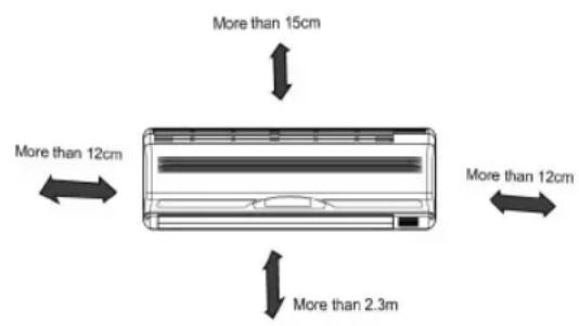
- Do not expose the indoor unit to heat or steam.
- Select a place where there are no obstacles in front or around the unit.
● Make sure that condensation drainage can be conveniently routed away.
● Do not install near a doorway. - Ensure that the space on the left and right of the unit is more than 12cm.
- Use a stud finder to locate studs to prevent unnecessary damage to the wall.
● A minimum pipe run of 3 metres is required to minimise vibration & excessive noise.
● The indoor unit should be installed on the wall at a height of 2.3 metres or more from the floor.
● The indoor unit should be installed allowing a minimum clearance of 15cm from the ceiling.
● Any variations in pipe length will/may require adjustment to refrigerant charge.
Outdoor unit
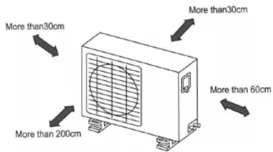
Split Air Conditioner
- If an awning is built over the outdoor unit to prevent direct sunlight or rain exposure, make sure that heat radiation from the condenser is not restricted.
- Ensure that the clearance around the back of the unit is more than 30cm and left side is more than 30cm. The front of the unit should have more than 200cm of clearance and the connection side (right side) should have more than 60cm of clearance.
- Do not place animals and plants in the path of the air inlet or outlet.
● Take the air conditioner weight into account and select a place where noise and vibration will not be an issue. - Select a place so that the warm air and noise from the air conditioner do not disturb neighbors.
Rooftop installation
- If the outdoor unit is installed on a roof structure, be sure to level the unit.
- Ensure the roof structure and anchoring method are adequate for the unit location.
- Consult local codes regarding rooftop mounting.
- If the outdoor unit is installed on roof structures or external walls, this may result in excessive noise and vibration, and may also be classed as a non serviceable installation.
Accessories
- Installation Plate x1
- Clip Anchor x 8
- Self-tapping Screw A ST3.9X25 x 8
- Seal x 1
- Drain Joint x 1
- Connecting pipe Assembly
Liquid side - ∅ 6,35
Gas side - ∅ 9,53 (12000Btu/h model),
∅12,7 (12000Btu/h model) (Parts you must purchase)
- Remote controller x 1
- Self-tapping Screw B ST2.9X10 x 2
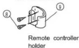
- Remote controller holder x 1
Note:
Except the above parts provided, the other parts needed during installation you must purchase.

Remote Controller

Mounting screw B
ST2.9x10-C-H
Caution
- Ensure that the space around the left and right of the indoor unit is more than 12cm.
● The indoor unit should be installed allowing a minimum clearance of 15cm from the ceiling.
Split Air Conditioner
- Use a stud finder to locate studs to prevent unnecessary damage to the wall.
● A minimum pipe run of 3 metres is required to minimise vibration & excessive noise.
● The indoor unit should be installed on the wall at a height of 2.3 metres or more from the floor.
● Two of the A, B and C directions should be free from obstructions.
Indoor unit installation
Fit the Installation Plate
- Fit the installation plate horizontally on structural parts of the wall with spaces around the installation plate.
- If the wall is made of brick, concrete or the like, drill eight (8) 5mm diameter holes in the wall. Insert Clip anchor for appropriate mounting screws.
- Fit the installation plate on the wall with eight (8) type "A" screws.
Drill a hole in the wall
- Determine hole positions according to the diagram detailed. Drill one (1) hole (65mm) slanting slightly to outdoor side.
- Always use wall hole conduit when drilling metal grid, metal plate or the like.

150mm or more to ceiling

A:780(<16000Btu/h model), 920(≥16000Btu/h model)

Note: Fit the Installation Plate and drill holes in the wall according to the wall structure and corresponding mounting points on the installation plate.
(Dimensions are in "mm" unless otherwise stated)
Connective Pipe and Drainage Installation
Drainage
- Run the drain hose sloping downward. Do not install the drain hose as illustrated below.

natural_image
Pure technical diagram showing two mechanical or electrical components with no text, numbers, or symbolsDo not block water flow by a rise.
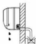
Do not put the end of drain hose into water.
Split Air Conditioner
- When connecting extension drain hose, insulate the connecting part of extension drain hose with a shield pipe, do not let the drain hose slack.
Connective pipe
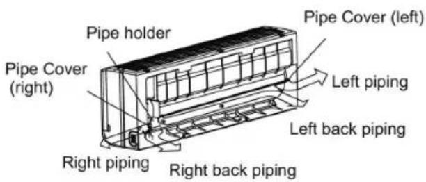
- For the left-hand and right-hand piping, remove the pipe cover from the side panel. Explain to clients that the pipe cover must be kept as it may be used when relocate the air conditioner to any other place.
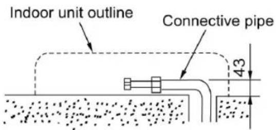
- For the rear-right-hand and rear-left-hand piping, install the piping as shown. Bend the connective pipe to be laid at 43mm height or less from the wall.
- Fix the end of the connective pipe. (Refer to Tightening Connection in REFRIGERANT PIPING CONNECTION)
Indoor unit installation
- Pass the piping through the hole in the wall.
- Put the upper claw at the back of the indoor unit on the upper hook of the installation plate, move the indoor unit from side to side to see that it is securely hooked.
- Piping can easily be made by lifting the indoor unit with a cushioning material between the indoor unit and the wall. Get it out after finish piping.
- Push the lower part of the indoor unit up on the wall, Then move the indoor unit from side to side, up and down to check if it is hooked securely.

Piping and wrapping
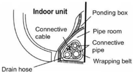
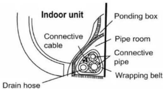
Bundle the tubing, connecting cable, and drain hose with tape securely, evenly as shown in Fig.10. Because the condensed water from rear of the indoor unit is gathered in ponding box and is piped out of room. Do not put anything else in the box.
Caution!
- Connect the indoor unit first, then the outdoor unit.
- Do not allow the piping to let out from the back of the indoor unit.
● Be careful not to let the drain hose slack.
● Heat insulated both of the auxiliary piping. - Be sure that the drain hose is located at the lowest side of the bundle. Locating at the upper side can cause drain pan to overflow inside the unit.
● Never intercross nor intertwist the power wire with any other wiring.
● Run the drain hose sloped downward to drain out the condensed water smoothly.
Outdoor installation precaution
● Install the outdoor unit on a rigid base to prevent increasing noise level and vibration.
● Determine the air outlet direction where the discharged air is not blocked.
Split Air Conditioner
- In the case that the installation place is exposed to strong wind such as a seaside, make sure the fan operating properly by putting the unit lengthwise along the wall or using a dust or shield plates.
● Specially in windy area, install the unit to prevent the admission of wind. - If need suspending installation, the installation bracket should accord with technique requirement in the installation bracket diagram. The installation wall should be solid brick, concrete or the same intensity construction, or actions to reinforce, damping supporting should be taken. The connection between bracket and wall, bracket and the air conditioner should be firm, stable and reliable.
- Be sure there is no obstacle which block radiating air.
Settlement of outdoor unit
Anchor the outdoor unit with a bolt and nut ∅10 or ∅8 tightly and horizontally on a concrete or rigid mount.
| Model A (mm) B (mm) | ||
| ≤ 3,5kWh 458 | 250 | |
| ≥ 3,5kWh | 548 266 | |
| 548 276 | ||

Drain joint installation
Fit the seal into the drain elbow, then insert the drain joint into the base pan hole of outdoor unit, rotate 90 to securely assemble them. Connecting the drain joint with an extension drain hose (Locally purchased), in case of the water draining off the outdoor unit during the heating mode.

Refrigerant piping connection

Flaring work
Main cause for refrigerant leakage is due to defect in the flaring work. Carry out correct flaring work using the following procedure:
Cut the pipes and the cable.
- Use the piping kit accessory or pipes purchased locally.
- Measure the distance between the indoor and the outdoor unit.
- Cut the pipes a little longer than the measured distance.
- Cut the cable 1.5m longer than the pipe length.
Burr removal
- Completely remove all burrs from the cut cross section of pipe/tube.
Split Air Conditioner
- Put the end of the copper tube/pipe in a downward direction as you remove burrs in order to avoid dropping burrs into the tubing.

Putting nut on
Remove flare nuts attached to indoor and outdoor unit, then put them on pipe/tube having completed burr removal.(not possible to put them on after flaring work)

Flaring work
Firmly hold copper pipe in a die in the dimension shown in the table below.
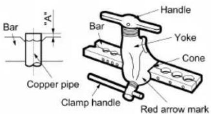
| Outer diam. (mm) | A (mm) | |
| Maks. MIn. | ||
| ∅6,35 1.3 0.7 | ||
| ∅9,53 1.6 1 | ||
| ∅12,7 1.8 1 | ||
Tightening Connection
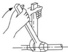
Align the center of the pipes.
Sufficiently tighten the flare nut with fingers, and then tighten it with a spanner and torque wrench as shown.

natural_image
Illustration of a hand using a tool to lift a mechanical component (no text or symbols)| Outer diam. | Tightening torque(N.cm) | Additional tightening torque(N.cm) |
| ∅6,35 | 1570 (160kgf/cm) | 1960 (200kgf/cm) |
| ∅9,53 | 2940 (300kgf/cm) | 3430 (350kgf/cm) |
| ∅12,7 | 4900 (500kgf/cm) | 5390 (550kgf/cm) |
Caution!
Excessive torque can break nut depending on installation conditions.
Electrical work
Electric safety regulations for the initial Installation
- If there is serious safety problem about the power supply, the technicians should refuse to install the air conditioner and explain to the client until the problem is solved.
- Power voltage should be in the range of 90%\~110% of rated voltage.
- The creepage protector and main power switch with a 1.5 times capacity of Max. Current of the unit should be installed in power circuit.
- Ensure the air conditioner is grounded well
- According to the attached Electrical Connection Diagram located on the panel of the outdoor unit to connect the wire.
- All wiring must comply with local and national electrical codes and be installed by qualified and skilled electricians.
Split Air Conditioner
- An individual branch circuit and single receptacle used only for this air conditioner must be available. See the following table for suggested wire sizes and fuse specifications:
NOTE:
The supply voltage must be consistent with the rate voltage of the air conditioner.
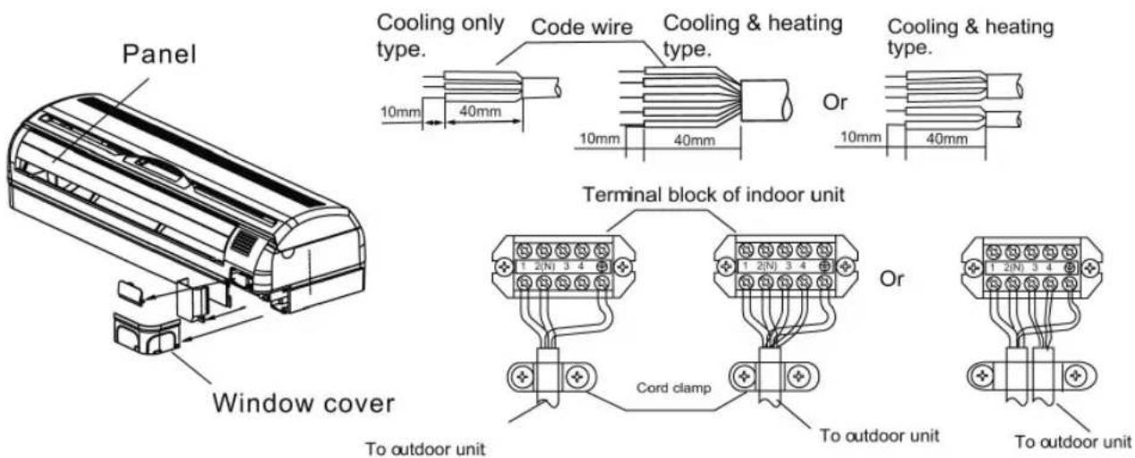
Connect the cable to the indoor unit
- Indoor/Outdoor connection cable should be H07RN-F type.
- Remove the screw, then remove the window cover.
- Connect cables according to their marks to terminals.
- Wrap those cables not connected with terminals with insulation tapes, so that they will not touch any electrical components.
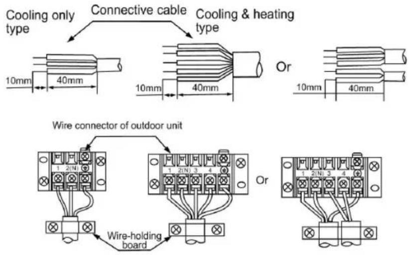
Connect the cable to the outdoor unit
- Remove the electric parts cover from the outdoor unit.
- Connect the connective cables to the terminals as identified with their respective matched numbers on the terminal block of indoor and outdoor units.
- To prevent the ingress of water, from a loop of the connective cable as illustrated in the installation diagram of indoor and outdoor units.
- Insulate unused cords (conductors) with PVC-tape. Process them so they do not touch any electrical or metal parts.
| Model Power supply | Input Rated Amp (Switch/Fuse) | Power Cord Size | |
| ≤ 12000Btu/h | 220-240V/50Hz | 10A 1,0/1,5 mm | ^2 |
| ≥12000Btu/h 16A 1,5 mm | ^2 | ||
Split Air Conditioner

Caution!
After the confirmation of the above conditions, prepare the wiring as follows:
- Never fail to have an individual power circuit specifically for the air conditioner. As for the method of wiring, be guided by the circuit diagram posted on the inside of control cover.
- The screw which fasten the wiring in the casing of electrical fittings are liable to come loose from vibrations to which the unit is subjected during the course of transportation. Check them and make sure that they are all tightly fastened. (If they are loose, it could cause burn-out of the wires.)
- Specification of power source.
- Confirm that electrical capacity is sufficient.
- See to that the starting voltage is maintained at more than 90 percent of the rated voltage marked on the name plate.
- Confirm that the cable thickness is as specified in the power source specification.
- Always install an earth leakage circuit breaker in a wet or moist area.
-
The following would be caused by voltage drop.
Vibration of a magnetic switch, which will damage the contact point, fuse breaking, disturbance of the normal function of the overload. -
The means for disconnection from a power supply shall be incorporated in the fixed wiring and have an air gap contact separation of at least 3mm in each active(phase) conductors.
Air Purging
Air and moisture in the refrigerant system have undesirable effects as indicated below:
Pressure in the system rises.
Operating current rises.
Cooling or heating efficiency drops.
Moisture in the refrigerant circuit may freeze and block capillary tubing. Water may lead to corrosion of parts in the refrigeration system.
Therefore, the indoor unit and tubing between the indoor and outdoor unit must be leak tested and evacuated to remove any noncondensables and moisture from the system.
Air purging with vacuum pump
● Preparation
Check that each tube(both liquid and gas side tubes) between the indoor and outdoor units have been properly connected and all wiring for the test run has been completed. Remove the service valve caps from both the gas and the liquid side on the outdoor unit. Note that both the liquid and the gas side service valves on the outdoor unit are kept closed at this stage.
● Pipe length and refrigerant amount:
Split Air Conditioner
| Connective pipe length | Air purging method | Dopełnienie czynnika chłodzącego |
| Less than 5m | Use vacuum pump. | |
| 5 - 10m | Use vacuum pump. | Liquid side: ∅6.35 (Pipe length-5) x30g |
- When relocate the unit to another place, perform evacuation using vacuum pump.
● Make sure the refrigerant added into the air conditioner is liquid form in any case.
Caution in handling the packed valve
(Not applicable to the units with R22)
- Open the valve stem until it hits against the stopper. Do not try to open it further.
- Securely tighten the valve stem cap with aspanner or the like.
● Valve stem cap tightening torque (See Tightening torque table in previous page).

flowchart
graph LR
    A["Outdoor unit"] --> B["A"]
    B --> C["Gas side"]
    C --> D["C"]
    D --> E["D"]
    E --> F["Indoor unit"]
    G["Packed valve"] --> H["B"]
    H --> I["Liquid side"]
    I --> J["D"]
    J --> K["Half union"]
    style A fill:#f9f,stroke:#333
    style B fill:#f9f,stroke:#333
    style C fill:#ccf,stroke:#333
    style D fill:#ccf,stroke:#333
    style E fill:#ccf,stroke:#333
    style F fill:#f9f,stroke:#333
    style G fill:#f9f,stroke:#333
    style H fill:#f9f,stroke:#333
    style I fill:#ccf,stroke:#333
    style J fill:#ccf,stroke:#333
    style K fill:#f9f,stroke:#333

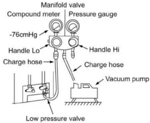
When Using the Vacuum Pump
(For method of using a manifold valve, refer to its operation manual.)
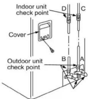
- Completely tighten the flare nuts, A, B, C, D, connect the manifold valve charge hose to a charge port of the low-pressure valve on the gas pipe side.
- Connect the charge hose connection to the vacuum pump.
- Fully open the handle Lo of the manifold valve.
- Operate the vacuum pump to evacuate. After starting evacuation, slightly loose the flare nut of the Lo valve on the gas pipe side and check that the air is entering (Operation noise of the vacuum pump changes and a compound meter indicates 0 instead of minus)
- After the evacuation is complete, fully close the handle Lo of the manifold valve and stop the operation of the vacuum pump.
Make evacuation for 15 minutes or more and check that the compound meter indicates -76cmHg (-1x10 Pa).
- Turn the stem of the packed valve B about 450 counterclockwise for 6\~7 seconds after the gas coming out, then tighten the flare nut again. Make sure the pressure display in the pressure indicator is a little higher than the atmosphere pressure.
- Remove the charge hose from the Low pressure charge hose.
- Fully open the packed valve stems B and A.
- Securely tighten the cap of the packed valve.
Electrical safety check
Perform the electric safe check after completing installation:
- Insulated resistance.
The insulated resistance must be more than 2M. - Grounding work.
Split Air Conditioner
After finishing grounding work, measure the grounding resistance by visual detection and grounding resistance tester. Make sure the grounding resistance is less than 4.
- Electrical leakage check (performing during test running)
During test operation after finishing installation, the serviceman can use the electroprobe and multimeter to perform the electrical leakage check. Turn off the unit immediately if leakage happens. Check and find out the solution ways till the unit operate properly.
Gas leak check
- Soap water method:
Apply a soap water or a liquid neutral detergent on the indoor unit connection or outdoor unit connections by a soft brush to check for leakage of the connecting points of th piping. If bubbles come out, the pipes have leakage.
- Leak detector
Use the leak detector to check for leakage.
Caution
A: Lo packed valve B: Hi packed valve
C and D are ends of indoor unit connection.
Test running
Perform test running after completing gas leak and electrical safety check.
The test running time should last more than 30 minutes.
-
Open the panel and lift the panel up to an angle which remains fixed. Do not lift the panel any further when it stops with a click sound.
-
Press the manual control button twice until the operating indicator lights up, the unit will operate on Forced Cool mode.
-
Check if all the functions works well during test running. Especially check whether the drainage of indoor or unit is smooth or not.
-
Press the manual switch button again after finishing the test running. The operating indicator turns dark and the unit stops operating.

Remote controller
Performance Features
- Operating Mode: AUTO COOL DRY HEAT(Cooling only model without) and FAN.
- Timer Setting Function in 24 hours.
- Indoor Setting Temperature Range : 17 C\~30 C.
- Full function of LCD (Liquid Crystal Display)
- Back light emitting(only available for R51M/BG(C)E models)
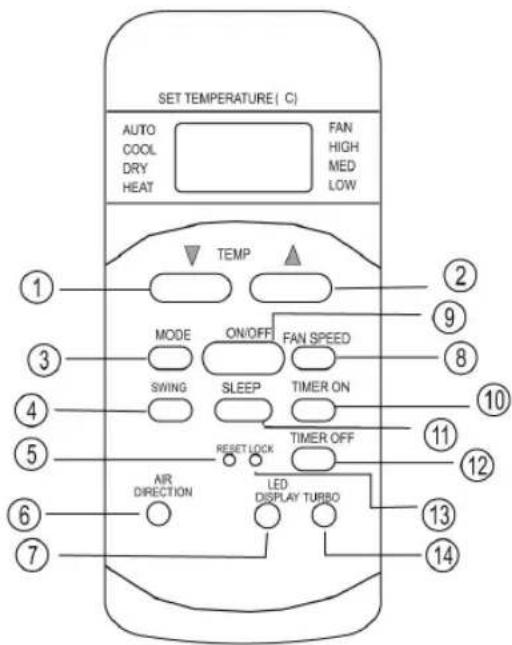
Split Air Conditioner
TEMP Button: Push this button to decrease the indoor temperature setting.
TEMP Button: Push this button to increase the indoor temperature setting.
MODE Selection Button: Each time the button is pressed, the operation mode is shifted in the direction of the arrow:

NOTE: COOL only model has no HEAT feature.
SWING Button: Push this switch button to change the louver angle.
RESET Button: When you press the recessed RESET button, all current settings are cancelled and the control will return to the initial settings.
AIR DIRECTION Button: Press this button and release it quickly the directional swing feature of the horizontal louver is activated.
The louver swings for a certain angle for each press. If keep pressing the button for more than 2 seconds, the Auto swing feature will be activated. Press it again, the louver stops moving.
When the louver swing at a position which would affect the cooling and heating effect of the air conditioner, it would automatically change the swing direction (Not applicable to units without this function).
LED DISPLAY Button: Press this button to clear the digit display in the air conditioner, press it again to activate it (Not available for the units without LED display window).
FAN SPEED Button: Used to select the Fan Speed in four steps- AUTO LOW MED or HIGH. Each time the button is pressed, the fan speed mode is shifted.
ON/OFF Button: Push this button to start operation, push the button again to stop operation.
TIMER ON Button: Press this button to initiate the auto-on time sequence. Each press will increase the auto-timed setting in 30 minutes increments. When the setting time displays 10:00, each press will increase the auto-timed setting 60 minutes increments.
To cancel the auto-timed program, simply adjust the auto-on time to 0:00.
SLEEP Button: Press this button to go into the Energy-Saving operation mode. Press it again to cancel. This function is only can be used on COOL, HEAT and AUTO mode and maintain the most comfortable temperature for you.
NOTE:
While the unit is running under SLEEP operation mode, it would be canceled if you press the other button.
TIMER OFF Button: Press this button to initiate the auto-off time sequence. Each press will increase the auto-timed setting in 30 minutes increments. When the setting time displays 10:00, each press will increase the auto-timed setting 60 minutes increments.
To cancel the auto-timed program, simply adjust the auto-off time to 0:00
LOCK Button: When you press the recessed LOCK button, all current settings are locked in and the remote controller does not accept any operation except that of the LOCK. Press again to cancel the LOCK mode.
TURBO Button: Push this button on COOL mode, the air conditioner goes into powerful cooling operation. Push again to cancel the TURBO function(Not available for the air conditioner without TURBO function).
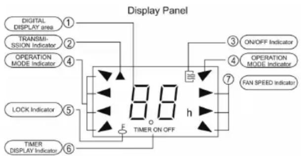
DIGITAL DISPLAY area: This area will show the set temperature and, if in the TIMER mode, will show the ON and OFF settings of the TIMER. If in the FAN mode, nothing is appeared.
TRANSMISSION Indicator: This indicator flashes one time when remote controller transmits signals to the indoor unit.
ON/OFF Indicator: This symbol appears when the unit is turned on by the remote controller, and disappear when the unit is turned off.
OPERATION MODE Indicator: When press the MODE button, it shows the current operating mode -- AUTO COOL DRY HEAT (Cooling only model without or „fan„) mode.
LOCK Indicator: LOCK display is displayed by pushing the LOCK button. Push the LOCK button to clear display.
TIMER DISPLAY Indicator: This display area shows the settings of the TIMER. That is, if only the starting time of operation is set, it will display the TIMER ON. If only the turning off time of operation
is set, it will display the TIMER OFF. If both operations are set, it will show TIMER ON-OFF which indicates you have chosen to set both the starting time and off time.
Split Air Conditioner
FAN SPEED Indicator: Press the FAN SPEED button to select the desired fan speed setting (Auto-Low-Med-High). You selection will be displayed in the LCD window except the Auto fan speed.
Note:
All signs shown in the Fig.2 is for the purpose of clear presentation. But during the actual operation only the relative functional signs are shown on the display panel.
Operating the Remote Controller
The Remote Controller uses two alkaline dry batteries (LR03X2).
- To install the batteries, slide the back cover of the battery compartment and install the batteries according the direction (+and -) shown on the Remote Controller.
- To replace the old batteries, use the same method as mentioned above.
Note:
- When replacing batteries, do not use old batteries or a different type battery. This may cause the remote control to malfunction.
- If you do not use the remote controller for several weeks remove the batteries. Otherwise battery leakage may damage the remote controller.
- The average battery life under normal use is about 6 months.
- Replace the batteries when there is no answering beep from the indoor unit or if the Transmission Indicator light fails to light.
Automatic operation
Switch on the power and the OPERATION indication lamp on the display panel of the indoor unit starts flashing, and turns off after flashes for 6 times.
- Use the MODE button to select AUTO.
- Push the TEMP button to set the desired room temperature.
The most comfortable temperature settings are between 21 C to 28 C.
-
Push the ON/OFF button to start the air conditioner. The OPERATION lamp on the display panel of the indoor unit lights. The FAN SPEED is automatically set and there are no fan speed indicators shown on the display panel of the remote controller.
-
Push the ON/OFF button again to stop the unit operation.
Note:
-
In the AUTO mode, the air conditioner can logically choose the mode of COOL, FAN and HEAT by sensing the difference between the actual ambient room temperature and the set temperature on the remote controller.
-
If the AUTO mode is not comfortable for you, the desired mode can be selected manually.
COOL/HEAT and FAN Operation
(Cooling only model without)
- If the AUTO mode is not comfortable, you may manually over-ride the settings by using COOL, HEAT or FAN modes.
- Push the TEMP button to set the desired room temperature.
When in COOLING mode, the most comfortable settings are 21 C or above. When in HEATING mode, the most comfortable settings are 28 C or below. - Push the FAN SPEED to select the FAN mode of AUTO, HIGH, MED or LOW.
- Push the ON/OFF button, the operation lamp lights and the air conditioner start to operate as your settings. Push the ON/OFF button again to stop this unit operation.
Note:
The FAN mode can not be used to control the temperature.
While in this mode, only steps 1 3 and 4 may be performed.
DRY operation
- Push the MODE button to select DRY.
- Push the TEMP button to set the desired temperature from 21 C to 28 C.
- Push the ON/OFF button, the OPERATION lamp lights and the air conditioner starts to operate in DRY mode at LOW fan speed. Push the ON/OFF button again to stop this unit operation.
Note:
Due to the difference of the set temperature of the unit and the actual indoor temperature, the Air Conditioner when in DRY mode will automatically operate many times without running the COOL and FAN mode.
TIMER operation
Push TIMER ON button to set the auto-on time and TIMER OFF button to set the auto-off time.
Split Air Conditioner
To set the starting time.
Push the TIMER ON button, then the remote controller shows TIMER ON, the last set time for the starting operation and the signal „h” will be shown on the DIGITAL DISPLAY area. You are now ready to reset the time to START the operation.
- Push the TIMER ON button again to set desired unit start time.
- After setting the TIMER ON, there will be a one-half second delay before the remote controller transmits the signal to the air conditioner. Then, after approximately another 2 seconds, the signal "h" disappears and the set temperature will re-appear on the digital display.
To set the stopping time.
- Push the TIMER OFF button and the remote controller will show TIMER OFF, the last set time for the stopping operation and the signal „h” will be shown on the DIGITAL DISPLAY area.
- You are now ready to reset the time of the STOP operation.
- Push the TIMER OFF button again to set the time you want to stop the operation.
- After setting the TIMER OFF, there will be a one-half second delay before the remote controller transmits the signal to the air conditioner. Then, after approximately another 2 seconds, the signal "h" disappears and the set temperature ill re-appear on the digital display.
Set the starting & stopping time
- Push the TIMER ON button, the remote controller will show TIMER ON, the last set time for START operation and the signal „h” will be shown on the DIGITAL display area. You are now ready to readjust the TIMER ON to start the operation.
- Push the TIMER ON button again to set the time you want to start the operation.
- Push the TIMER OFF button, the remote controller will show TIMER OFF, the last set time for STOP operation and the signal „h” will be shown on the DIGITAL display area. You are now ready to reset the time to STOP operation.
- Push the TIMER OFF button again to set the time you want to stop the operation.
- After setting the TIMER, there will be a one-half second delay before the remote controller transmits the signal to the Air Conditioner. Then, after approximately another 2 seconds, the signal „h“ disappears and the set temperature will re-appear on the digital display.
Change the TIMER
To change the TIMER ON/OFF time, just press the corresponding TIMER button and reset the time.
To cancel the TIMER ON/OFF setting, just adjust the TIMER time to 0:00.
Note:
The setting time is relative time. That is the time set is based on the delay of the current time.
Warning!
- Be sure there are no obstacles between the remote controller and the receiver of indoor unit otherwise the air conditioner will not work.
- Keep the Remote Controller away from any liquids.
- Protect the remote controller from the high temperatures and exposure to radiation.
- Keep the indoor receiver out of direct sunlight or the Air Conditioner may malfunction.
- Keep Remote Controller away from EMI (Electro-Magnetic Interference) supplied by other household appliances.
Specification
Model: R51M/(C)E, R51M/BG(C)E
Tated Voltage: 3.0V (Alkaline dry batteries LR03 x 2)
Lowest Voltage of CPU: 2.0V
Transmission Distance:
8m (when using 3.0 voltage, it Gets 11m)
Environment: -5^ 60^ ( -41^ 140^ )
Split Air Conditioner
Troubleshooting
| Stop the air conditioner immediately if one of the following faults occur. Disconnect the power and contact the nearest customer service center | |
| Trouble | OPERATION indicator or other indicators flash rapidly(5 times every second) and this flash cannot be fixed by disconnecting the power, and then connect it again |
| Fuse blows frequently or circuit breaker trips frequently | |
| Other objects or water penetrate the air conditioner | |
| The remote controller won’t work or works abnormally | |
| Other abnormal situations | |
| Malfunctions Cause What should be done? | ||
| Unit does not start | Power cutUnit may have become unpluggedFuse may have blownBattery in Remote controller may have been exhaustedThe time you have set with timer is incorrect | Wait for power to be restored.Check that plug is securely in wall receptacleReplace the fuseReplace the batteryWait or cancel timer setting |
| Unit not cooling or heating (Cooling/heating models only) room very well while air flowing out from the air conditioner | Inappropriate temperature settingAir filter is blockedDoors or Windows are openAir inlet or outlet of indoor or outdoor unit has been blockedCompressor 3 minutes protection has been activated | Set temperature correctly. For detailed method please refer to „Using remote control” sectionClean the air filterClose the doors or windowsClear obstructions away first, then restart the unitWait. |
| Notes: Do not attempt to repair the unit yourself. Always consult an authorised service provider. | ||
Split Air Conditioner
Návod k obsluze
natural_image
Technical line drawing of a layered air conditioner unit with airflow direction indicated (no text or symbols)natural_image
Simple line drawing of a cartoon-style air conditioner unit with arrows indicating airflow or movement (no text or symbols)UPOZORNĚNÍ


natural_image
Line drawing of hands holding a device with arrows indicating movement or force (no text or symbols)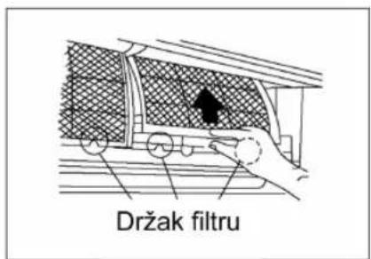

natural_image
Diagram showing a mechanical component with a downward arrow indicating force or direction (no text or symbols present)Split Air Conditioner
Údržba
natural_image
Illustration of a hand using a wrench to lift a mechanical component (no text or symbols)UPOZORNĚNÍ:
INSTALACE ELEKTRICKÁ
natural_image
Technical line drawing of a layered air conditioner unit with a stack of sheets and a hand holding the lid (no text or symbols)natural_image
Cartoon illustration of a smiling air conditioner unit with airflow arrows indicating airflow direction (no text or symbols)Split Air Conditioner
FIGYELEM

natural_image
Diagram of a device with hands holding a transparent casing, showing internal components and directional arrows (no text or symbols)
natural_image
Hand placing a dark arrow on a patterned panel inside a vehicle (no text or symbols visible)natural_image
Illustration of two hands inserting a grid of small objects into a rectangular grid (no text or symbols)Split Air Conditioner
natural_image
Hand placing a grid-patterned object into a car air vent with an arrow indicating upward motion (no text or symbols)Karbantartás
natural_image
Pure technical diagram showing two mechanical or electrical components with no text, numbers, or symbolsnatural_image
Pure technical diagram of a mechanical or electrical component without any text, numbers, or symbolsnatural_image
Illustration of a hand using a tool to lift a mechanical component (no text or symbols)FIGYELEM
natural_image
Black vacuum cleaner with coiled hose and control panel (no visible text or symbols)natural_image
Top-down view of a white foam drain with internal massage equipment (no text or symbols visible)- MM415 Microwave
- Split Air Conditioner
- Návod k obsluze
- Uwaga!
- Konserwacja
- Always do this
- Never to this
- Energy Save
- Operating condition
- Caution!
- Description
- Indoor unit
- Outdoor unit
- Dosplay
- Note:
- Manual operation
- Optimal operation
- Adjusting air flow direction
- Adjusting the Vertical Air Flow Direction (up - down)
- To set the vertical air flow direction
- To set the horizontal air flow direction (left - right)
- To automatically swing the air flow direction (up - down)
- How the air conditioner works
- Automatic operation
- Sleep operatikon
- Drying operation
- Maintenance
- Cleaning the air filter
- Operation tips
- Protection of the air conditioner
- A white mist coming out from the indoor unit
- Low noise of the air conditioner
- Dust is blown out from the indoor unit.
- A peculiar smell comes out from the indoor unit.
- The air conditioner turns to FAN only mode from COOL or HEAT (For cooling and heating models only) mode.
- Dripping water may generate on the surface of the indoor unit when cooling in a high relatively humidity (relative humidity higher than 80%).
- Heating mode (For cooling and heating models only)
- Auto-restart function
- Lightning or a car wireless telephone operating nearby may cause the unit to malfunction.
- Installation of indoor and outdoor units
- Rooftop installation
- Accessories
- Caution
- Indoor unit installation
- Fit the Installation Plate
- Drill a hole in the wall
- Connective Pipe and Drainage Installation
- Drainage
- Connective pipe
- Piping and wrapping
- Outdoor installation precaution
- Settlement of outdoor unit
- Drain joint installation
- Refrigerant piping connection
- Flaring work
- Cut the pipes and the cable.
- Burr removal
- Putting nut on
- Tightening Connection
- Electrical work
- Connect the cable to the indoor unit
- Connect the cable to the outdoor unit
- Air Purging
- Air purging with vacuum pump
- Caution in handling the packed valve
- When Using the Vacuum Pump
- Electrical safety check
- Test running
- Remote controller
- Performance Features
- Operating the Remote Controller
- COOL/HEAT and FAN Operation
- DRY operation
- TIMER operation
- To set the starting time.
- To set the stopping time.
- Set the starting & stopping time
- Change the TIMER
- Warning!
- Specification
- UPOZORNĚNÍ
- Údržba
- UPOZORNĚNÍ:
- INSTALACE ELEKTRICKÁ
- FIGYELEM
- Karbantartás
Brand : Manta
Model : MMS12
Category : Air conditioner