
eServer xSeries 305 - Server IBM - Free user manual and instructions
Find the device manual for free eServer xSeries 305 IBM in PDF.


| Product Type | 1U Rack Server |
| Brand | IBM |
| Model | eServer xSeries 305 |
| Dimensions (H x W x D) | 4.3 cm x 44.5 cm x 61.0 cm (1U x 19 inches x 24 inches) |
| Weight | Approximately 12.7 kg (28 lb) |
| Power Supply | 200-240 V, 50/60 Hz power supply, 200 W power |
| Processor | Up to 2 Intel Pentium 4 or Xeon processors |
| Memory (RAM) | Up to 4 GB DDR SDRAM |
| Storage | 2 bays for SATA or SCSI hard drives |
| Network Connectivity | 2 x 10/100/1000 Ethernet ports |
| Main Features | Entry-level server for small businesses, remote management possible |
| Maintenance and Cleaning | Regular dusting, maintain ambient temperature between 10°C and 35°C |
| Security | Chassis lock, BIOS password, compliance with electrical safety standards |
| Spare Parts and Repairability | Power supply, fans, hard drives, memory, motherboard (subject to availability) |
Frequently Asked Questions - eServer xSeries 305 IBM
User questions about eServer xSeries 305 IBM
0 question about this device. Answer the ones you know or ask your own.
Ask a new question about this device
Download the instructions for your Server in PDF format for free! Find your manual eServer xSeries 305 - IBM and take your electronic device back in hand. On this page are published all the documents necessary for the use of your device. eServer xSeries 305 by IBM.
USER MANUAL eServer xSeries 305 IBM
natural_image
Abstract geometric pattern with red and black diagonal stripes on white background (no text or symbols)IBM

xSeries 305 Type 8673
Hardware Maintenance Manual and Troubleshooting Guide
Note
Before using this information and the product it supports, read Appendix C, "Notices" on page 121.
Aboutthismanual
This manual contains diagnostic information, a Symptom-to-FRU index, service information, error codes, error messages, and configuration information for the IBM @serverrxSeries™ 305.
Important: The field replaceable unit (FRU) procedures are intended for trained servicers who are familiar with IBM xSeries products. See the parts listing in "Server" on page 80 to determine if the component being replaced is a customer replaceable unit (CRU) or a field replaceable unit (FRU).
The latest version of this publication is available from the IBM Web site. Go to http://www.ibm.com/ and click Support & downloads. In the Technical support keyword search field, type 8673 and click Go. A list of publications for your server is displayed.
Important safety information
Be sure to read all caution and danger statements in this book before performing any of the instructions. See "Safety information" on page 87.
You can download the most current diagnostic, BIOS flash, and device driver files from http://www.ibm.com/pc/support on the World Wide Web.
Contents
Aboutthismanual.
Important safety information . . . . . . . . . . . . . . . . . . . . . . . i i i
Online support. i v
Chapter1.Generalinformation. 1
Related publications. 1
Notices and statements in this book. 2
Features and specifications. 3
Server Controls, LEDs and power. 4
Front view. 4
Rear view. 5
Server power features. 6
Chapter2.Configuringyourserver. 9
Using the Configuration/Setup Utility program. 9
Starting the Configuration/Setup Utility program. 9
Passwords. 1 0
Using the ServerGuide Setup and Installation CD . . . . . . . . . . . . . . 11
ServerGuide features . . . . . . . . . . . . . . . . . . . . . 11
Setup and configuration overview. 1 2
System Partition 1 3
Typical operating-system installation . . . . . . . . . . . . . . . . 1 3
Setting up or updating multiple servers. 1 3
Installing your operating system without ServerGuide. 1 4
Using the SCSISelect Utility program. 1 4
Starting the SCSISelect Utility program . . . . . . . . . . . . . . . 1 4
SCSISelect Utility menu choices . . . . . . . . . . . . . . . . . . 1 4
Configuring the Gigabit Ethernet controller. 1 5
High-performance Ethernet options . . . . . . . . . . . . . . . . . 1 5
Chapter3.Diagnostics. 17
General checkout 17
Checkout procedure . . . . . . . . . . . . . . . . . . . . . . . 1 8
Diagnostic tools overview. 1 9
POST. 1 9
POST beep codes . . . . . . . . . . . . . . . . . . . . . . 2 0
Error logs. 20
ServerGuide error symptoms. 2 0
Small computer system interface messages ..... 2 1
Diagnostic programs and error messages. 2 1
Text messages. 2 2
Starting the diagnostic programs 2 2
Diagnostic error message tables. 2 4
Recovering the BIOS code 2 4
Updating the UUID . . . . . . . . . . . . . . . . . . . . . . . . . 2 6
Updating the DMI/SMBIOS data 2 6
Power checkout 2 6
Troubleshooting the Ethernet controller . . . . . . . . . . . . . . . . . 27
Network connection problems 27
Ethernet controller troubleshooting chart 27
Ethernet controller messages 28
Chapter4.Customerreplaceableunits 2 9
Installation guidelines 29
System reliability guidelines. 2 9
Handling static-sensitive devices. 2 9
Major components of the xSeries 305 Type 8673. . . . . . . . . . . . . 3 0
System-board illustrations. 3 1
System-board and riser-card option connectors. 3 1
System-board internal cable connectors. 3 2
System-board external port connectors ..... 3 2
System-board switches and jumpers 3 3
System-board LEDs. 3 3
Removing the cover. 3 4
Removing the front bezel . . . . . . . . . . . . . . . . . . . . . . 3 5
Working with adapters 3 5
Adapter considerations. 3 6
Installing an adapter 3 8
Hard disk drives 40
Installing or replacing a hard disk drive . . . . . . . . . . . . . . . . 4 0
Installing DIMMs 4 1
Completing the installation. 4 2
Installing the cover. 4 2
Updating your server configuration. 4 3
Replacing the battery 43
Input/output ports and connectors. 4 5
Serial port. 4 5
Viewing or changing the serial-port assignments . . . . . . . . . . 4 5
Serial-port connector. 4 6
Universal Serial Bus ports. 4 6
USB cables and hubs 4 6
USB-port connectors. 4 6
Keyboard connector. 4 6
Video connector 47
Auxiliary-device (pointing device) connector . . . . . . . . . . . . . 4 7
Gigabit Ethernet port. 47
Configuring the Gigabit Ethernet controller. 4 7
High-performance Ethernet modes. 4 8
Ethernet port connector. 4 8
Cabling the server. 4 8
Chapter 5. Removing and installing FRUs (service only) ..... 51
Removing the cover. 5 1
Thermal grease. 5 2
Removing and replacing a microprocessor. 5 3
Removing and replacing the retention module. 5 4
Removing and replacing the system board. 5 5
Removing and replacing the switch/LED/USB card. 5 6
Removing and replacing a power supply . . . . . . . . . . . . . . . 5 7
Removing the front bezel. 5 8
Removing and replacing the PCI riser card . . . . . . . . . . . . . . . 5 9
Removing and replacing the fans . . . . . . . . . . . . . . . . . . . . 6 0
Removing and replacing the blower. 6 1
Removing and replacing the air baffle . . . . . . . . . . . . . . . . . 6 2
Chapter 6. Symptom-to-FRU index . . . . . . . . . . . . . . . . . . . . . . . . . . . . . . 63
Beep symptoms. 6 3
No beep symptoms 6 5
Diagnostic error codes 6 5
Error symptoms 6 8
POST error codes. 6 9
POST (ISPR) error procedures ..... 7 3
ServeRAID error codes 7 5
Undetermined problems 7 7
Chapter7.PartslistingxSeries305Type8673. 7 9
Server 80
Keyboard CRUs 8 1
Power cords. 8 2
AppendixA.Gettinghelpandtechnicalassistance. 8 5
Before you call 8 5
Using the documentation 8 5
Getting help and information from the World Wide Web . . . . . . . . . . 8 5
Software service and support 8 6
Hardware service and support. 8 6
AppendixB.Relatedserviceinformation 87
Safety information. 8 7
General safety 87
Electrical safety. 8 8
Safety inspection guide 8 9
Handling electrostatic discharge-sensitive devices . . . . . . . . . . . 9 0
Grounding requirements 9 1
Safety notices (multilingual translations). 9 1
AppendixC.Notices. 1 2 1
Trademarks. 1 2 1
Important notes . . . . . . . . . . . . . . . . . . . . . . . . . . . 1 2 2
Electronic emission notices 1 2 3
Federal Communications Commission (FCC) statement ..... 1 2 3
Industry Canada Class A emission compliance statement. . . . . . . . 123
Australia and New Zealand Class A statement. 123
United Kingdom telecommunications safety requirement. . . . . . . 1 2 3
European Union EMC Directive conformance statement 1 2 4
Taiwanese Class A warning statement. 124
Japanese Voluntary Control Council for Interference (VCCI) statement 124
Chapter1.Generalinformation
The IBM @serverxSeries 305 Type 8673 server, which features IBM
X-Architecture ™ technology, is a high-performance server. It is ideally suited for networking environments that require superior microprocessor performance, efficient memory management, flexibility, and large amounts of reliable data storage.
Performance, reliability, and expansion capabilities were key considerations in the design of your server. These design features make it possible for you to customize the system hardware to meet your needs today, while providing flexible expansion capabilities for the future.
If you have access to the Internet, you can obtain up-to-date information about your server and other IBM server products at http://www.ibm.com/eserver/xseries/ on the World Wide Web.
Relatedpublications
This Hardware Maintenance Manual and Troubleshooting Guide is provided in PDF on the IBM xSeriesDocumentationCD. It contains information to help you solve the problem yourself or to provide helpful information to a service technician.
In addition to this Hardware Maintenance Manual and Troubleshooting Guide, the following xSeries 345 Type 8670 documentation is provided with your server:
•InstallationGuide
This printed publication contains setup and installation instructions.
•RackInstallationInstructions
This printed publication contains the instructions to install your server in a rack.
•SafetyBook
This multilingual publication is provided in Portable Document Format (PDF) on the IBM xSeriesDocumentationCD. It contains translated versions of the caution and danger statements that appear in the documentation for your server. Each caution and danger statement has an assigned number, which you can use to locate the corresponding statement in your native language.
-User'sGuide
This publication is provided in PDF on the IBM xSeriesDocumentationCD. It contains general information about your server, including information about features, how to configure your server, how to use the ServerGuide ™ Setupand InstallationCD, and how to get help.
-OptionInstallationGuide
This publication is provided in PDF on the IBM xSeriesDocumentationCD. It contains instructions to install, remove, and connect optional devices supported by your server.
Depending on your server model, additional publications might be included on the IBM xSeriesDocumentationCD.
Noticesandstatementsinthisbook
The caution and danger statements used in this book also appear in the multilingual Safety Information book provided on the IBM xSeries Documentation CD. Each caution and danger statement is numbered for easy reference to the corresponding statements in the safety book.
The following types of notices and statements are used in this book:
- Note: These notices provide important tips, guidance, or advice.
- Important: These notices provide information or advice that might help you avoid inconvenient or problem situations.
- Attention: These notices indicate possible damage to programs, devices, or data. An attention notice is placed just before the instruction or situation in which damage could occur.
- Caution: These statements indicate situations that can be potentially hazardous to you. A caution statement is placed just before the description of a potentially hazardous procedure step or situation.
- Danger: These statements indicate situations that can be potentially lethal or extremely hazardous to you. A danger statement is placed just before the description of a potentially lethal or extremely hazardous procedure step or situation.
Featuresandspecifications
The following table provides a summary of the features and specifications of your xSeries 305 Type 8673 server. Depending on your server model, some features and specifications might not apply.
Racks are marked in vertical increments of 1.75 inches. Each increment is referred to as a unit, or "U." A 1-U-high device is 1.75 inches tall.
Table1. Featuresandspecifications
| Microprocessor:Memory:Minimum: 256 MBMaximum: 4 GBType: PC2100 266 MHz, ECC SDRAM, registered DIMMs onlySlots: Four dual inlineSupports 256 MB, 512 MB, and 1 G B D I M M sDrives:Diskette: 1.44 MBCD-ROM: IDESupports up to two slim-high hard disk drivesExpansionbays:Expansionslots:Two 66/100/133 MHz/64-bit PCI-X slots on the system board (one half-length full-height, one low profile)Videocontroller:ATI Rage XL video on system boardCompatible with SVGA and VGA8 MB SDRAM video memoryPowersupply: | Size:Height: 43 mm (1.75 inches, 1 U)Depth: 424 mm (16.54 inches)Width: 430 mm (16.69 inches)Maximum weight: 12.7 kg (28 lb) depending on your configurationIntegratedfunctions:1000Base-T, 100Base-T, 10Base-T (dual) Ethernet controllers on the system board with Wake on LAN® supportSerial portTwo USB portsKeyboard portMouse portDual-channel bus mastering IDE controllerHarddiskcontroller:Dual-channel bus mastering IDE controllerUltra160 SCSI adapter is installed in one of the expansion slots (SCSI models)Acousticalnoiseemissions:Sound power, idling: 6.5 bel maximumSound power, operating: 6.5 bel maximumEnvironment:Air temperature:- Server on: 10° to 35°C (50.0° to 95.0°F); altitude: 0 to 914 m (2998.7 ft)- Server off: -40° to 60°C (-104° to 140°F); maximum altitude: 2133 m (6998.0 ft)Humidity:- Server on: 8% to 80%- Server off: 8% to 80% | Heatoutput:Approximate heat output in British thermal units (Btu) per hour:Minimum configuration: 297 Btu (87 watts)Maximum configuration: 512 Btu (150 watts)Electricalinput:Sine-wave input (47-63 Hz) requiredInput voltage low range:- Minimum: 100 V ac- Maximum: 127 V acInput voltage high range:- Minimum: 200 V ac- Maximum: 240 V acInput kilovolt-amperes (kVA), approximately:- Minimum: 0.0870 kVA- Maximum: 0.150 kVANotes:1. Power consumption and heat output vary depending on the number and type of optional features installed and the power-management optional features in use.2. These levels were measured in controlled acoustical environments according to the procedures specified by the American National Standards Institute (ANSI) S12.10 and ISO 7779 and are reported in accordance with ISO 9296. Actual sound-pressure levels in a given location might exceed the average values stated because of room reflections and other nearby noise sources. The declared sound-power levels indicate an upper limit, below which a large number of computers will operate. |
ServerControls,LEDsandpower
This section describes the controls and light-emitting diodes (LEDs) and how to turn the server on and off.
Frontview
The following illustration shows the controls and LEDs on the front of the server.
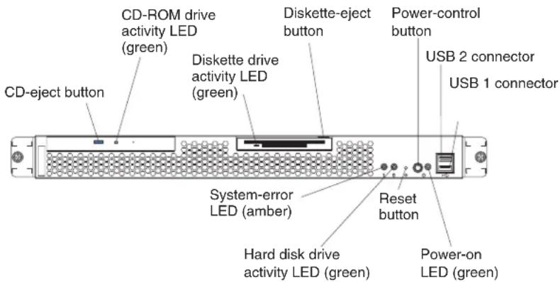
CD-ejectbutton: Press this button to release a CD from the CD-ROM drive.
CD-ROMdriveactivityLED: When this LED is lit, it indicates that the CD-ROM drive is in use.
DiskettedriveactivityLED: When this LED is lit, it indicates that the diskette drive is in use.
Diskette-ejectbutton: Press this button to release a diskette from the diskette drive.
Power-controlbutton: Press this button to turn the server on and off manually.
USB2Connector: Connect a USB device to this connector.
USB1Connector: Connect a USB device to this connector.
Power-onLED: When this LED is lit, it indicates that the server is turned on.
Resetbutton: Press this button to reset the server and run the power-on self-test (POST). You might have to use a pen or the end of a straightened paper clip to press the button.
HarddiskdriveactivityLED: When this LED is flashing, it indicates that the associated hard disk drive is in use.
System-errorLED: When this LED is lit, it indicates that a system error has occurred.
Rearview
The following illustration shows the LEDs on the rear of the server.

Ethernet2linkLED(green):When this green LED is lit, it indicates that the speed of the Ethernet LAN is 1000BASE-T. When this green LED is off, it indicates that the speed of the Ethernet LAN is 10/100BASE-T.
Ethernet2activityLED(green):When this green LED is flashing, it indicates that there is an active link connection between Ethernet port 2 and the network.
Ethernet1linkLED(green):When this green LED is lit, it indicates that the speed of the Ethernet LAN is 1000BASE-T. When this green LED is off, it indicates that the speed of the Ethernet LAN is 10/100BASE-T.
Ethernet1activityLED(green):When this green LED is flashing, it indicates that there is an active link connection between Ethernet port 1 and the network.
Serverpowerfeatures
This section contains information about how to turn your server on and off.
Turningontheserver
Statement13:

DANGER
Overloadingabranchcircuitispotentiallyafirehazardandashockhazard undercertainconditions.Toavoidthesehazards,ensurethatyoursystem electricalrequirementsdonotexceedbranchcircuitprotection requirements.Refertotheinformationthatisprovidedwithyourdevicefor electricalspecifications.
After you connect the server to an ac power source, the server can be turned on in any of the following ways:
- You can press the power-control button on the front.
- If the server is turned on and a power failure occurs, the server will start automatically when power is restored. (You can set the default in the Configuration/Setup Utility program. Go to PowerManagement→Automatic Poweron→PreviousState.)
Complete the following steps to manually turn on the server:
- Review the information in "Important safety information" on page iii.
- Turn on all external devices, such as the monitor.
- Plug the server power cord into the power source.
- Press the power-control button on the front of the server.
Note: While the server is turning on, the power-on LED on the front of the server is lit.
Turningofftheserver
Complete the following steps to manually turn off the server:
- Review the information in "Important safety information" on page iii
- See your operating system documentation for the proper procedure to shut down the operating system.
When you turn off the server, observe the following precaution.
- Press the power-control button on the front of the server.
Statement5:

CAUTION:
The power control button on the device and the powers switch on the powers supply don't turn off the electrical currents supplied to the device. The device also must have more than one power cord. Toremove all electrical current from the device, ensure that all power cords are disconnected from the powers source.

Chapter2.Configuringyourserver
The following configuration programs and capabilities come with your server:
- Configuration/SetupUtilityprogram
This is part of the basic input/output system (BIOS) in your server. Use it to configure serial port assignments, change interrupt request (IRQ) settings, change the startup-device sequence, set the date and time, and set passwords.
• IBMServerGuideSetupandInstallationCD
This provides software-setup tools and installation tools that are designed for your server. Use this CD during the installation of your server to configure basic hardware features and to simplify the installation of your operating system. For information about using this CD, see "Using the ServerGuide Setup and Installation CD" on page 11
•SCSISelectUtilityprogram(somemodels)
Use this to configure devices that are attached to the SCSI adapter. Use it to change default settings, resolve configuration conflicts, and perform low-level formats on SCSI hard disk drives. For information about using this utility program, see "Using the ServerGuide Setup and Installation CD" on page 11.
•GigabitEthernetcontrollerconfiguration
Your server comes with two integrated Gigabit Ethernet controllers. These controllers provide an interface for connecting to a 10-Mbps, 100-Mbps, or 1000-Mbps network and provides full-duplex (FDX) capability, which enables simultaneous transmission and reception of data on the Ethernet local area network (LAN).
•IBMDirector
IBM Director is a workgroup-hardware-management tool that you can use to centrally manage xSeries servers; IBM NetVista ™ , IntelliStation ® , and ThinkPad ® computers; and non-IBM Intel-microprocessor-based systems. IBM Director automates tasks such as inventory-taking, monitoring of environmental sensors (such as temperature, voltage and fans), alerting, and system-health information. For more information about IBM Director, see the IBMDirectorCDthat comes with your server.
UsingtheConfiguration/SetupUtilityprogram
Use the Configuration/Setup Utility program to:
•View configuration information
•View and change assignments for devices and I/O ports
- Set the date and time
- Set and change passwords and Remote Control Security settings
- Set the startup characteristics of the server and the order of startup devices
- Set and change settings for advanced hardware features
•View and clear error logs
StartingtheConfiguration/SetupUtilityprogram
Complete the following steps to start the Configuration/Setup Utility program:
- Turn on the server.
- When the prompt Press F1 for Configuration/Setup appears, press F1. If you have set both a power-on password and an administrator password, you must
type the administrator password to access the full Configuration/Setup Utility menu. If you do not type the administrator password, a limited Configuration/Setup Utility menu is available.
- Select settings to view or change.
Passwords
From the SystemSecuritychoice, you can set, change, and delete a power-on password. The SystemSecuritychoice is on the full Configuration/Setup menu only.
If you set a power-on password, you must type the power-on password to complete the system startup, and you have access to the full Configuration/Setup Utility menu.
If you set a power-on password for a user and an administrator password for a system administrator, you can type either password to complete the system startup. A system administrator who types the administrator password has access to the full Configuration/Setup Utility menu; the system administrator can give the user authority to set, change, and delete the power-on password. A user who types the power-on password has access to only the limited Configuration/Setup Utility menu; the user can set, change, and delete the power-on password, if the system administrator has given the user that authority.
Power-onpassword
If a power-on password is set, when you turn on the server, the system startup will not be completed until you type the power-on password. You can use any combination of up to seven characters (A-Z, a-z, and 0-9) for the password.
When a power-on password is set, you can enable the Unattended Start mode, in which the keyboard and mouse remain locked but the operating system can start. You can unlock the keyboard and mouse by typing the power-on password.
If you forget the power-on password, you can regain access to the server in any of the following ways:
- If an administrator password is set, type the administrator password at the password prompt. Start the Configuration/Setup Utility program and reset the power-on password.
- Remove the server battery and then reinstall it. See the Option Installation Guide for instructions for removing the battery.
Administratorpassword
If an administrator password is set, you must type the administrator password for access to the full Configuration/Setup Utility menu. You can use any combination of up to seven characters (A–Z, a–z, and 0–9) for the password. The Administrator password choice is on the Configuration/Setup Utility menu only if an optional IBM Remote Supervisor Adapter is installed.
Attention: If you set an administrator password and then forget it, there is no way to change, override, or remove it. You must replace the system board.
UsingtheServerGuideSetupandInstallationCD
The ServerGuideSetupandInstallationCD includes an easy-to-use setup and installation program that is designed for your IBM server. The ServerGuide program detects the server model and hardware options that are installed and uses that information during setup to configure the hardware. The ServerGuide program simplifies operating-system installations by providing updated device drivers and, in some cases, installing them automatically.
To purchase the latest ServerGuideSetupandInstallationCD, see the "ServerGuideUpdates" flyer that comes with your server library, or go to the ServerGuide fulfillment Web site at http://www.ibm.com/pc/coupon/.
The ServerGuide program has the following features to make setup easier:
- An easy-to-use interface with online help
- Diskette-free setup, and configuration programs that are based on detected hardware
- ServeRAID Manager program, which configures your ServeRAID adapter or integrated SCSI controller with RAID capabilities if installed
- A system BIOS update program, which updates the BIOS code directly from the CD
•Device drivers that are provided for your server model and detected hardware
- Operating-system partition size and file-system type that are selectable during setup
ServerGuidefeatures
Features and functions can vary slightly with different versions of the ServerGuide program. To learn more about the version that you have, start the ServerGuide SetupandInstallationCD and view the online overview. Not all features are supported on all server models.
The ServerGuide program requires a supported IBM server with an enabled startable (bootable) CD-ROM drive. In addition to the ServerGuideSetupand InstallationCD, you must have your operating-system CD to install your operating system.
The ServerGuide program has the following features:
- Sets system date and time.
- If installed, detects the SCSI RAID adapter, controller, or integrated SCSI controller with RAID capabilities and runs the SCSI RAID configuration program.
- Updates the licensed internal code (firmware) level without diskettes.
- Checks the system BIOS code and microcode (firmware) levels of supported options to determine whether a later level is available from the CD. You can perform updates without using diskettes.
- Creates a System Partition on the default drive. You can run server-specific utility programs after setup.
- Detects installed hardware options and provides updated device drivers for most adapters and devices.
- Creates a setup-replication diskette for replicating setup selections for other servers of the same model.
- Provides diskette-free installation for supported operating systems.
- Provides a replicated installation path for multiple installations of supported operating systems.
- Includes an online README file with links to tips for your hardware and operating-system installation.
Setupandconfigurationoverview
When you use the ServerGuideSetupandInstallationCD, you do not need setup diskettes. You can use the CD to configure any supported IBM server model. The ServerGuide program checks your system BIOS, service processors, and other system hardware to determine if system updates are available. The setup program provides a list of tasks that are required to set up your server model. On a server with a ServeRAID adapter or integrated SCSI controller with RAID capabilities, you can run the SCSI RAID configuration program to create logical drives.
Note: Features and functions can vary slightly with different versions of the ServerGuide program.
When you start the ServerGuideSetupandInstallationCD, the program performs the following tasks:
- The ServerGuide program prompts you for your language, country, and keyboard layout. (This information is stored and later passed to the operating-system installation program.)
- The ServerGuide program displays choices for running the configuration programs. For example:
- The Express Configuration method runs the required programs for your server, based on the hardware that is detected.
- The Custom Configuration method displays all programs that are available for your server, and you decide which programs to run.
- The Replicated Configuration method provides the option of duplicating your setup selections to other servers that are the same model.
- If you select the Custom Configuration method, the following features are optional. If you select the Express Configuration method, some or all of these features are run, depending on the hardware that is detected:
- The Set Date and Time feature is provided so that you do not have to use the Configuration/Setup Utility program to access these settings.
– The Clear Hard Disks feature is provided so you can delete all partitions on all hard disk drives. - The ServerGuide program checks the server BIOS code and microcode (firmware) levels for supported options and then checks the CD for a newer level. The CD content might be newer than the BIOS code and firmware level. The ServerGuide program can perform a flash update of the BIOS code and supported microcode (firmware) options without using diskettes.
- The SCSI RAID configuration program starts, leading you through the entire configuration process.
- The ServerGuide program creates a System Partition on the default drive.
- The ServerGuide program displays a confirmation summary, so that you will know when you have completed all the required tasks. Then, you are ready to install your operating system.
Notes:
-
Plug and Play adapters are configured automatically. Non-Plug and Play adapters or non-IBM adapters might require switch settings, additional device drivers, and installation after the operating system is installed. See the documentation that comes with the adapter.
-
Diagnostics for your server come in BIOS code or on a separate diagnostics CD.
SystemPartition
The ServerGuide program creates a 50 MB System Partition on the default drive. The System Partition contains server-specific utility programs such as service-processor disk operating system (DOS) utilities, system diagnostics, flash BIOS updates, and other programs. Programs in the System Partition vary by server model, and not all server models run utility programs from the System Partition. To determine which ones do, start the ServerGuideSetupandInstallation CD and view the online overview.
After setup is complete, you can access programs in the System Partition by restarting the server and pressing Alt+F1 when the prompt is displayed. The SystemPartitionmenu displays the programs that are available on your server model.
Typicaloperating-systeminstallation
You can use the ServerGuide program to shorten your installation time. The ServerGuide program provides the device drivers that are required for your hardware and for the operating system that you are installing. This section describes a typical ServerGuide operating-system installation.
Note: Features and functions can vary slightly with different versions of the ServerGuide program.
- After you have completed the setup process, the operating-system installation program starts. (You will need your operating-system CD to complete the installation.)
- The ServerGuide program stores information about the server model, service processor, hard disk drive controllers, and network adapters. Then, the program checks the CD for newer device drivers. This information is stored and then passed to the operating-system installation program.
- With some operating-system installations, you can create an operating-system replication diskette for setting up additional servers. This diskette contains the Internet protocol (IP) address, server name, and other selections.
- The ServerGuide program presents operating-system partition options that are based on your operating-system selection and the installed hard disk drives.
- If you are installing the operating system from diskettes, the ServerGuide program lists the diskettes that you must create and the optional device-driver diskettes (for installed adapters or controllers) that you might want to create.
- The ServerGuide program prompts you to insert your operating-system CD and restart the server. At this point, the installation program for the operating system takes control to complete the installation.
Settinguporupdatingmultipleservers
You can use the ServerGuide program to create diskettes that help you set up or update multiple servers. You can modify information on the diskettes as you use them to set up or update other servers.
Note: Availability and function can vary by server model and by the hardware that is installed.
You can create a setup-replication diskette, which contains your hardware configuration selections. Use this diskette to replicate selections to other servers that are of the same model.
You can create an operating-system replication diskette, which contains information that you need to complete multiple installations. Not all operating systems support operating-system replication diskettes.
InstallingyouoperatingsystemwithoutServerGuide
If you have already configured the server hardware and you decide not to use the ServerGuide program to install your operating system, complete the following steps to download the latest operating-system installation instructions from the IBM Support Web page:
- Go to http://www.ibm.com/pc/support/.
- Under Browse, click Servers.
- From the Familydrop-down list, select your server model.
- If operating-system installation instructions are available for your server model, OS installation is in the list in the upper-left corner of the Web page. Click OS installation and select the instructions for your operating system.
UsingtheSCSISelectUtilityprogram
Use the SCSISelect Utility program to:
•View the default SCSI IDs
- Locate and correct configuration conflicts
- Perform a low-level format on a SCSI hard disk
StartingtheSCSISelectUtilityprogram
Complete the following steps to start the SCSISelect Utility program:
- Turn on the server.
- When the prompt <<< Press
for SCSISelect Utility! >>> appears, press Ctrl+A. If you have set an administrator password, you are prompted to type the password. - When the prompt Would you like to configure the SCSISelect controller or run the SCSI Disk Utilities? appears, make your selection and press Enter.
- Use the arrow keys to select a choice from the menu.
- Follow the instructions on the screen to change the settings of the selected items, and press Enter.
SCSISelectUtilitymenuchoices
The following choices are on the SCSISelect Utility menu:
-Configuration
Select this choice to view or change SCSI controller settings. To reset the controller to its default settings, press F6 and follow the instructions on the screen.
You can view and change the following controller settings:
- SCSIControllerID
Select this choice to view the SCSI controller ID, which is typically 7.
- SCSIControllerParity
This choice is set to Enabled and cannot be changed.
- SCSIControllerTermination
This choice is set to Enabled and cannot be changed.
•AdditionalConfiguration
Select this choice to view or change the setting for advanced configuration options. These options include support for large hard disk drives and support for drives with Ultra SCSI speeds.
- BootDeviceOptions
Select this choice to configure startable-device parameters. You must know the SCSI ID of the device that you want to configure.
- SCSlDeviceConfiguration
Select this choice to configure SCSI-device parameters. You must know the SCSI ID of the device that you want to configure.
The sync transfer rate is the transfer rate for Ultra SCSI devices. For Ultra3 SCSI LVD devices, the maximum rate is 160 MBps; for Ultra2 SCSI devices, 80 MBps; for Fast SCSI devices, 20 MBps.
•BIOSInformation
- Interrupt(IRQ)Channel
Select this choice to view the Change Interrupt Request settings.
- I/OPortAddress
Select this choice to view the Input/Output ports.
•SCSIDiskUtilities
Select this choice to view the SCSI ID that is assigned to a device or to format a SCSI device. Select a device from the list and read the instructions on the screen carefully before making a selection.
If you press Ctrl+A before a selected drive is ready, an Unexpected SCSI Command Failure screen might appear. Restart the server and watch the SCSISelect messages as each drive spins up. When the selected drive is ready, press Ctrl+A.
ConfiguringtheGigabitEthernetcontroller
Your server comes with two integrated Gigabit Ethernet controllers. The controllers provide an interface for connecting to a 10-Mbps, 100-Mbps, or 1-Gbps local area network (LAN) and provides full-duplex (FDX) capability, which enables simultaneous transmission and reception of data on the network.
When you connect the server to a network, the Ethernet controllers detect the data-transfer rate (10 Mbps, 100 Mbps, or 1 Gbps) of the network and automatically operates at that rate. If the Ethernet ports that your server is connected to auto-negotiation, the controllers automatically operate in standard Ethernet (10BASE-T), Fast Ethernet (100BASE-TX/1000BASE-T), half duplex (HDX), or full duplex (FDX) mode. The controllers supports 1 GB speeds.
High-performanceEthernetoptions
The Ethernet controllers support teaming options, virtual LANs, and priority packets, which improve performance, security, and throughput. These options are supported by the integrated Ethernet controller and by adapters such as the IBM 10/100/1000 Ethernet Adapter and the IBM 10/100/1000 EtherJet PCI family of adapters.
Teamingoptions
The Ethernet controller supports teaming options. A team consists of two or more integrated Ethernet controllers, two or more Ethernet adapters, or a combination of
Ethernet controllers and adapters. Teaming options improve throughput and fault tolerance on a server running Microsoft Windows 2000, Windows NT 4.0, Linux, or Novell NetWare 4.1x or later. The controller supports the following teaming options:
- Adapter fault tolerance (AFT) provides automatic redundancy for Ethernet controllers. It supports from two to four controllers per team. You can configure one of the integrated Ethernet controllers or adapters as the primary controller. If the primary connection fails, the secondary controller takes over. When the primary connection is restored, network traffic returns to the primary controller.
- Adaptive load balancing (ALB) balances data transmission among two to four controllers. ALB includes AFT. You can use ALB with any 100BASE-TX/1000BASE-T switch.
- CiscoFastEtherChannel(FEC) improves transmission and reception throughput among two to four controllers. FEC includes AFT. You can use FEC only with a switch that has FEC capability.
Chapter3.Diagnostics
This section provides basic troubleshooting information to help you resolve some common problems that might occur with your server.
If you cannot locate and correct the problem using the information in this section, see Appendix A, "Getting help and technical assistance" on page 85 for more information.
Generalcheckout
The server diagnostic programs are stored on the IBM EnhancedDiagnosticsCD. These programs provide the primary methods of testing the major components of the server.
If you cannot determine whether a problem is caused by the hardware or by the software, you can run the diagnostic programs to confirm that the hardware is working properly.
When you run the diagnostic programs, a single problem might cause several error messages. When this occurs, work to correct the cause of the first error message. After the cause of the first error message is corrected, the other error messages might not occur the next time you run the test.
A failed system might be part of a shared hard disk drive cluster (two or more systems sharing one or more external storage devices). Before you run diagnostics, verify that the failing system is not part of a shared hard disk drive cluster.
A system might be part of a cluster if:
•The system is identified as part of a cluster.
•One or more external storage units are attached to the system and at least one of the attached storage units is also attached to another system or unidentifiable source.
•One or more systems are located near the failing system.
If the failing system is suspected to be part of a shared hard disk drive cluster, you can run all diagnostic tests except the diagnostic tests that test the storage unit (hard disk drive residing in the storage unit) or the storage adapter attached to the storage unit.
Notes:
-
For systems that are part of a shared hard disk drive cluster, run one test at a time in looped mode. Do not run all tests in looped mode, because this could enable the hard disk drive diagnostic tests.
-
If multiple error codes are displayed, diagnose the first error code that is displayed.
-
If the computer stops with a POST error, go to "POST error codes" on page 69.
-
If the computer stops and no error is displayed, go to "Undetermined problems" on page 77.
-
For power supply problems, see "Power checkout" on page 26.
-
For safety information, see "Safety information" on page 87.
-
For intermittent problems, check the error log.
Checkoutprocedure
Follow the steps in this procedure to identify system problems.
001 ISTHESYSTEMPARTOFACLUSTER?
YES. Schedule maintenance for the system. Shut down all systems related to the cluster. Run the storage test.
NO.Go to step 002.
002 IFTHESYSTEMISNOTPARTOFACLUSTER:
- Turn off the server and all external devices.
- Check all cables and power cords.
- Set all display controls to the middle position.
- Turn on all external devices.
- Turn on the server.
- Record any POST error messages that are displayed on the screen. If an error is displayed, look up the first error in the "POST error codes" on page 69.
- Check the System Error log. If an error was recorded by the system, see Chapter 6, "Symptom-to-FRU index" on page 63
- Start the diagnostic programs.
- Check for the following responses:
•One beep. - Readable instructions or the main menu.
003 DIDYOURECEIVEBOTHOFTHECORRECTRESPONSES?
NO. Find the failure symptom in Chapter 6, "Symptom-to-FRU index" or page 63.
YES.Run the diagnostic programs. If necessary, see "Diagnostic programs and error messages" on page 21.
If you receive an error, see Chapter 6, "Symptom-to-FRU index" on page 63.
If the diagnostic programs were completed successfully and you still suspect a problem, see "Undetermined problems" on page 77
Diagnostictoolsoverview
The following tools are available to help you identify and resolve hardware-related problems:
•POSTbeepcodesanderrormessages
The power-on self-test (POST) generates beep codes and messages to indicate successful test completion or the detection of a problem. See “POST” for more information.
- Errorlog
The POST error log contains the three most recent error codes and messages that the system has generated during POST. The System Error Log contains all the error messages that were issued during POST.
To view the contents of the error logs, start the Configuration/Setup Utility program; then, select ErrorLogsfrom the main menu. See "Viewing the System Error log" on page 24 for more information.
•ServerGuideerrorsymptoms
ServerGuide error symptoms are explained at "ServerGuide error symptoms" on page 20.
•Diagnosticprogramsanderrormessages
The server diagnostic programs are stored on the IBM EnhancedDiagnostics CD. These programs are the primary method of testing the major components of your server. See "Diagnostic programs and error messages" on page 21 for more information.
- Errorsymptomcharts
These charts list problem symptoms, along with suggested steps to correct the problems. See the "Error symptoms" on page 68 for more information.
- Customizedsupportpage
You can create a customized support page that is specific to your hardware, complete with Frequently Asked Questions, Parts Information, Technical Hints and Tips, and Downloadable files. In addition, you can choose to receive electronic mail (e-mail) notifications whenever new information becomes available about your registered products.
After you register and profile your xSeries products, you can diagnose problems using the IBM Online Assistant, and you can participate in the IBM discussion forum. For more detailed information about registering and creating a customized profile for your IBM products, go to the following addresses on the Web:
- http://www.ibm.com/pc/register
– http://www.ibm.com/pc/support
POST
When you turn on the server, it performs a series of tests to check the operation of server components and some of the options installed in the server. This series of tests is called the power-on self-test, or POST.
Notes:
-
If you have a power-on password or administrator password set, you must type the password and press Enter, when prompted, before POST will continue.
-
A single problem might cause several error messages. When this occurs, work to correct the cause of the first error message. After you correct the cause of the first error message, the other error messages usually will not occur the next time you run the test.
POSTbeepcodes
POST generates beep codes to indicate successful completion or the detection of a problem.
•One short beep indicates the successful completion of POST.
- More than one beep indicates that POST detected a problem. For more information, see "Beep symptoms" on page 63.
If POST detects a problem (more than one beep sounds), an error message appears on your screen. See "Beep symptoms" on page 63 and "POST error codes" on page 69 for more information.
Errorlogs
A POST error log is available when an optional service processor adapter has been installed in the server.
The POST error log contains the three most recent error codes and messages that the system generated during POST. The System Error log contains all messages issued during POST and all system status messages from the service processor.
You can view the contents of the System Error log from the Configuration/Setup Utility program or from the diagnostic programs.
ViewingerrorlogsfromtheConfiguration/SetupUtilityprogram
Start the Configuration/Setup Utility program; then, select ErrorLogsfrom the main menu. See Chapter 2, "Configuring your server" on page 9 for more information.
Viewingerrorlogsfromdiagnosticprograms
Start the diagnostic programs; select HardwareInfo from the top of the diagnostic programs screen; select SystemErrorLog from the list that appears; then, follow the instructions on the screen. See "Starting the diagnostic programs" on page 22 for more information.
ServerGuideerrorsymptoms
Look for the symptom in the left column of the chart. Probable solutions to the problem are in the right column.
Table2.ServerGuideSetupandInstallationCD
| SymptomSuggestedaction | |
| The ServerGuide Setupand InstallationCD will not start. | ·Ensure that the server is supported and has a startable (bootable) CD-ROM drive.·If the startup (boot) sequence settings have been altered, ensure that the CD-ROM drive is first in the startup sequence.·If more than one CD-ROM drive is installed, ensure that only one drive is set as the primary drive. Start the CD from the primary drive. |
| The SCSI RAID program cannot view all installed drives, or the NOS cannot be installed. | ·Ensure that there are no duplicate SCSI IDs or IRQ assignments.·Ensure that the hard disk drive is connected properly. |
| The Operating System Installation program continuously loops. | Make more space available on the hard disk. |
| The ServerGuide program will not start your NOS CD. | Ensure that the NOS CD you have is supported by the ServerGuide program. See the ServerGuideSetupandInstallationCD label for a list of supported NOS versions. |
| The NOS cannot be installed; the option is not available. | Ensure that the NOS is supported on your server. If the NOS is supported, either there is no logical drive defined (SCSI RAID systems) or the ServerGuide System Partition is not present. Run the ServerGuide program, and ensure that setup is complete. |
Smallcomputersysteminterfacemessages
If you receive a SCSI error message, see "Diagnostic error codes" on page 65.
Note: If your server does not have a hard disk drive, ignore any message that indicates that the BIOS is not installed.
Diagnosticprogramsanderrormessages
The server diagnostic programs are stored on the IBM EnhancedDiagnosticsCD. These programs are the primary method of testing the major components of your server.
Diagnostic error messages indicate that a problem exists; they are not intended to be used to identify a failing part. Troubleshooting and servicing of complex problems that are indicated by error messages should be performed by trained service personnel.
Sometimes the first error to occur causes additional errors. In this case, the server displays more than one error message. Always follow the suggested action instructions for the firsterror message that appears.
The following sections contain the error codes that might appear in the detailed test log and summary log when the diagnostic programs are run.
The error code format is as follows:
fff-ttt-iii-date-cc-text message
where:
fffis the three-digit function code that indicates the function being tested when the error occurred. For example, function code 089 is for the microprocessor.
tttis the three-digit failure code that indicates the exact test failure that was encountered. (These codes are for trained service personnel; see "Diagnostic error codes" on page 65).
iii is the three-digit device ID. (These codes are for trained service personnel; see "Diagnostic error codes" on page 65).
dateis the date that the diagnostic test was run and the error recorded.
ccis the check value that is used to verify the validity of the information.
textmessageis the diagnostic message that indicates the reason for the problem.
Textmessages
The diagnostic text message format is as follows:
Function Name: Result (test specific string)
where:
FunctionName
is the name of the function being tested when the error occurred. This corresponds to the function code (fff) shown in the error code format in the previous section.
Resultcan be one of the following:
PassedThis result occurs when the diagnostic test is completed without any errors.
FailedThis result occurs when the diagnostic test discovers an error.
UserAbortedThis result occurs when you stop the diagnostic test before it is complete.
NotApplicable
This result occurs when you specify a diagnostic test for a device that is not present.
AbortedThis result occurs when the test could not proceed, for example, because of the system configuration.
WarningThis result occurs when a possible problem is reported during the diagnostic test, such as when a device driver is not found.
testspecificstring
is additional information that you can use to analyze the problem.
Startingthediagnosticprograms
The IBM Enhanced Diagnostics programs will isolate your server hardware from software that you have installed on your hard disk drive. The programs run independently of the operating system, and mustberuneitherfromtheCDor diskette. This method of testing is generally used when other methods are not accessible or have not been successful in isolating a problem suspected to be hardware related.
An IBM Enhanced Diagnostics CD comes with the server. You can also download the latest image of the diagnostics from the World Wide Web at http://www.ibm.com/pc/support.
Note: When using diagnostics with a USB Keyboard and Mouse attached, go into Setup and enable USB emulation.
- Press F1 Config/Setup
- Select Devices and I/O Ports
- Select USB Setup
- Make sure USB Keyboard and Mouse are enabled.
UsingthediagnosticsCD
To start the IBM Enhanced Diagnostics using the CD, do the following:
-
Turn off your server and any peripheral devices.
-
Turn on all attached devices; then, turn your server on.
- When you see Press F1 For Configuration/Setup, press the F1 key.
- When the Configuration/Setup Utility menu appears, select StartOptions.
- From the Start Options menu, select StartupSequence.
- Note the device selected as the First Startup Device. Later, you must restore this setting.
- Select CD-ROM as the First Startup Device.
- Press Esc two times to return to the Configuration/Setup Utility menu.
- Place the IBM Enhanced Diagnostics CD in the CD-ROM drive.
- Select Save&ExitSetup and follow the prompts. The diagnostics will load. Follow the instructions on the screen to run the diagnostics.
Important: When you finish running the diagnostics and utilities, remove the CD from the CD-ROM drive and turn off the server. You must restore the First Startup Device to the original setting. Use steps 2 through 8 of this procedure to do this.
Downloadingthediagnosticsprogram
Do the following to download the latest image of the IBM Enhanced Diagnostics from the World Wide Web and create a startable Enhanced Diagnostics diskette:
- Go to the following World Wide Web site: http://www.ibm.com/pc/support/
- Download the diagnostics file for your server to a hard disk drive directory (not to a diskette).
- Go to a DOS prompt and change to the directory where the file was downloaded.
- Insert a blank high-density diskette in diskette drive A.
- Type in the following, and then press Enter: filename a: where filename is the name of the file you downloaded from the Web.
The downloaded file is self-extracting and will be copied to the diskette. When the copy completes, you have a startable IBM Enhanced Diagnostics diskette.
Usingthediagnosticdiskette
Do the following to start the IBM Enhanced Diagnostics using the diagnostics diskette, do the following:
- Turn off your server and any peripheral devices.
- Insert the IBM Enhanced Diagnostics diskette into the diskette drive.
- Turn on all attached devices; then, turn on the server.
- Follow the instructions on the screen.
- Place the IBM EnhancedDiagnosticsCD in the CD-ROM drive. The diagnostics will load. Follow the instructions on the screen to run the diagnostics.
When the tests have completed, you can view the Test Log by selecting Utility from the top of the screen.
If the hardware checks out OK but the problem persists during normal server operations, a software error might be the cause. If you suspect a software problem, refer to the information that comes with the software package.
Viewingthetestlog
The test log records data about system failures and other pertinent information. The test log will not contain any information until after the diagnostic program has run.
Note: If you already are running the diagnostic programs, begin with step 4
- Insert the IBMEnhancedDiagnosticsCD.
- Turn on the system and watch the screen.
If the system is on, shut down your operating system and restart the system. - If a power-on password is set, the system prompts you for it. Type in the appropriate password; then, press Enter.
- Run the appropriate diagnostics program and when the Diagnostic Programs screen appears, select Utility.
- Select View Test Log from the list that appears; then, follow the instructions on the screen.
- You can save the test log to a file on a diskette or to your hard disk drive.
Note: The system maintains the test-log data while the system is powered on. When you turn off the power to the server, the test log is cleared.
ViewingtheSystemErrorlog
With the optional service processor adapter, you can also view the System Error log from the diagnostic programs. See the instructions in "Viewing error logs from diagnostic programs" on page 20.
Diagnosticerrormessagetables
For descriptions of the error messages that might appear when you run the diagnostic programs, see "Diagnostic error codes" on page 65.
Notes:
- Depending on your server configuration, some of the error messages might not appear when you run the diagnostic programs.
- If diagnostic error messages appear that are not listed in the tables, make sure that your server has the latest levels of BIOS, Advanced System Management Processor, ServeRAID ™ , and diagnostics microcode installed.
RecoveringtheBIOScode
If the BIOS code has become damaged, such as from a power failure during a flash update, you can recover the BIOS code using the boot block jumper and a BIOS flash diskette.
Note: You can obtain a BIOS flash diskette from one of the following sources:
- Use the ServerGuideSetupandInstallationCD to make a BIOS flash diskette.
- Download a BIOS flash diskette from the World Wide Web. Go to http://www.ibm.com/pc/support, click IBMServerSupport, and make the selections for your server.
- Contact your IBM service representative.
The flash memory of your server contains a protected area that cannot be overwritten. The recovery boot block is a section of code in this protected area that enables the server to start up and to read a flash diskette. The flash utility recovers the system BIOS code from the BIOS recovery files on the diskette.
The following illustration shows the location of the Flash boot block recovery jumper on the system board.

Note: The Automatic Server Restart (ASR) jumper (JP3) causes the server to restart automatically if it stops (for example, if the operating system stops running). The default position of the jumper (ASR enabled) is pins 2 and 3.
Complete the following steps to recover the BIOS code:
-
Turn off the server and disconnect all power cords and external cables; then, remove the server cover (see "Removing the cover" on page 34).
-
Locate the Flash boot block recovery jumper block (JP4) on the system board.
-
Move the jumper from pins 1 and 2 to pins 2 and 3 to enable the BIOS recovery mode.
-
Insert the BIOS flash diskette into the diskette drive.
-
Reinstall the server cover; then, reconnect all power cords.
-
Restart the server. The system begins the power-on self test (POST).
-
Select 1-UpdatePOST/BIOS from the menu that contains various flash update options.
-
When prompted as to whether you want to save the current code to a diskette, press N.
-
When prompted to choose a language, select a language (from 0 to 7) and press Enterto accept your choice.
-
Do not restart your server at this time.
-
Remove the BIOS flash diskette from the diskette drive.
-
Turn off the server and disconnect all power cords and external cables; then, remove the server cover.
-
Remove the jumper from the Flash boot block recovery jumper block, or move it to pins 1 and 2 to return to normal startup mode.
-
Reconnect all external cables and power cords and turn on the peripheral devices; then, reinstall the server cover.
UpdatingtheUUID
The Universal Unique Identifier (UUID) must be updated when the system board is replaced. Complete the following steps to update the UUID:
- Copy the UUID utility ("uuid.exe") from the BIOS flash diskette to a DOS bootable diskette.
- Insert the diskette created in step 1 into the server.
- Restart the server from the diskette.
- At the "A:" prompt, type UUID /wr; then, press Enter. The utility will generate a random identifier.
- Restart the server.
UpdatingtheDMI/SMBIOSdata
The Desktop Management Interface (DMI) must be updated when the system board is replaced. Complete the following steps to update the DMI:
- Copy the DMI/SMBIOS utility ("extrmdmi.exe") from the BIOS flash diskette to a DOS bootable diskette.
- Insert the diskette created in step 1 into the server.
- Restart the server from the diskette.
- At the "A:" prompt, type extrmdmi.exe; then, press Enter.
- To change the machine type and model number, type mtm XXXXYYY
where XXXX is the model type and YYY is the model number; then, press Enter.
- To change the serial number, type sn ZZZZZZZ
where ZZZZZZZ is the serial number; then, press Enter.
- To change the asset tag, type asset AAAAAAAAAAAAAAAAAAAAAAAAAAAAAAAAAAAAA
where AAAAAAAAAAAAAAAAAAAAAAAAAAAAAA is the asset tag number; then, press Enter.
- Restart the server.
Powercheckout
Power problems can be difficult to solve. For example, a short circuit can exist anywhere on any of the power distribution buses. Usually a short circuit will cause the power subsystem to shut down because of an overcurrent condition.
A general procedure for troubleshooting power problems is as follows:
- Turn off the server and disconnect all ac power cords.
- Check for loose cables in the power subsystem. Also check for short circuits, for example, if there is a loose screw causing a short circuit on a circuit board.
-
Remove adapters and disconnect the cables and power connectors to all internal and external devices until the server is at the minimum configuration required to start the server (see "Minimum operating requirements" on page 7).
-
Reconnect all ac power cords and turn on the server. If the server starts up successfully, replace adapters and devices one at a time until the problem is isolated. If the server does not start up from the minimal configuration, replace FRUs of minimal configuration one at a time until the problem is isolated.
To use this method, it is important to know the minimum configuration required for a system to start (see page 77).
TroubleshootingtheEthernetcontroller
This section provides troubleshooting information for problems that might occur with the 10/100/1000 Mbps Ethernet controller.
Networkconnectionproblems
If the Ethernet controller cannot connect to the network, check the following conditions:
• Make sure that the cable is installed correctly.
The network cable must be securely attached at all connections. If the cable is attached but the problem remains, try a different cable.
If you set the Ethernet controller to operate at either 100 Mbps or 1000 Mbps, you must use Category 5 or higher cabling.
- Determine whether the hub supports auto-negotiation. If it does not, try configuring the integrated Ethernet controller manually to match the speed and duplex mode of the hub.
- Check the Ethernet controller LEDs on the operator information panel and on the rear of the server.
These LEDs indicate whether a problem exists with the connector, cable, or hub.
- The Ethernet transmit/receive activity LED, on the operator information panel, is lit when the Ethernet controller sends or receives data over the Ethernet Network. If the Ethernet transmit/receive activity LED is off, make sure that the hub and network are operating and that the correct device drivers are installed.
- The Ethernet link status LED, on the rear of the server, is lit when the Ethernet controller receives a LINK pulse from the hub. If the LED is off, there might be a defective connector or cable or a problem with the hub.
- Make sure that you are using the correct device drivers which are supplied with your server.
- Check for operating-system-specific causes for the problem.
- Make sure that the device drivers on the client and server are using the same protocol.
•Test the Ethernet controller.
The way the Ethernet controller is tested depends on which operating system you are using (see the Ethernet controller device driver README files).
Ethernetcontrollertroubleshootingchart
Use the following troubleshooting chart to find solutions to 10/100/1000 Mbps Ethernet controller problems that have definite symptoms.
Table3.Ethernettroubleshootingchart
| Ethernetcontroller problem | FRU/actions |
| The server stops running when loading device drivers. | The PCI BIOS interrupt settings are incorrect.Check the following:·Determine if the interrupt (IRQ) setting assigned to the Ethernet controller is also assigned to another device in the Configuration/Setup Utility program.Although interrupt sharing is allowed for PCI devices, some devices do not function well when they share an interrupt with a dissimilar PCI device. Try changing the IRQ assigned to the Ethernet controller or the other device. For example, for NetWare Versions 3 and 4, it is recommended that disk controllers not share interrupts with LAN controllers.·Make sure that you are using the most recent device driver available from the World Wide Web.·Reseat or replace the adapter. |
| Ethernet link status LED does not work. | Check the following:·Make sure that the hub is turned on.·Check all connections at the Ethernet controller and the hub.·Use another port on the hub.·If the hub does not support auto-negotiation, manually configure the Ethernet controller to match the hub.·If you manually configured the Duplex mode, make sure that you also manually configure the speed.·Reseat or replace the adapter. |
| The Ethernet transmit/receive activity LED does not work. | Check the following:·Make sure that you have loaded the network device drivers.·The network might be idle. Try sending data from this server. |
| Data is incorrect or sporadic. | Check the following:·Make sure that you are using Category 5 or higher cabling when operating the server at 100 Mbps or at 1000 Mbps.·Make sure that the cables do not run close to noise-inducing sources like fluorescent lights. |
| The Ethernet controller stopped working when another adapter was added to the server. | Check the following:·Make sure that the cable is connected to the Ethernet controller.·Make sure that your PCI system BIOS code is current.·Reseat the adapter.·Determine if the interrupt (IRQ) setting assigned to the Ethernet adapter is also assigned to another device in the system. Use the Configuration/Setup Utility program to determine if this is the case.Although interrupt sharing is allowed for PCI devices, some devices do not function well when they share an interrupt with a dissimilar PCI device. Try changing the IRQ assigned to the Ethernet adapter or the other device.·Reseat or replace the adapter. |
| The Ethernet controller stopped working without apparent cause. | Check the following:·Try a different connector on the hub.·Reinstall the device drivers. See your operating-system documentation and the ServerGuide information.·Reseat or replace the adapter. |
Ethernetcontroller messages
The integrated Ethernet controller might display messages from certain device drivers. The latest information available concerning these messages will be made available at the IBM Support Web site at http://www.ibm.com/pc/support.
Chapter4.Customerreplaceableunits
This chapter provides instructions for adding options to your server. Some option-removal instructions are provided in case you need to remove one option to install another.
Installationguidelines
Before you begin installing options in your server, read the following information:
- Read "Handling static-sensitive devices" and "Safety information" on page 81. "Handling static-sensitive devices". This information will help you work safely with your server and options.
- Make sure that you have an adequate number of properly grounded electrical outlets for your server, monitor, and other devices that you will connect to the server.
- Back up all important data before you make changes to disk drives.
- Have a small Phillips screwdriver available.
- For a list of supported options for your server, go to http://www.ibm.com/pc/compat/ on the World Wide Web.
Systemreliabilityguidelines
To help ensure proper system cooling and system reliability, make sure that:
•Each of the drive bays has a drive or a filler panel.
- Space is available around the server to allow the server cooling system to work properly. Refer to the documentation that comes with the rack.
- You have followed the cabling instructions that come with optional adapters.
- You have replaced a failed fan as soon as possible.
Handlingstatic-sensitivedevices
Attention: Static electricity can damage electronic devices, including your server. To avoid damage, keep static-sensitive devices in their static-protective packages until you are ready to install them.
To reduce the possibility of damage from electrostatic discharge, observe the following precautions:
- Limit your movement. Movement can cause static electricity to build up around you.
- Handle the device carefully, holding it by its edges or its frame.
- Do not touch solder joints, pins, or exposed circuitry.
- Do not leave the device where others can handle and damage it.
- While the device is still in its static-protective package, touch it to an unpainted metal part of the server for at least 2 seconds. This drains static electricity from the package and from your body.
- Remove the device from its package and install it directly into the server without setting down the device. If it is necessary to set down the device, place it back into its static-protective package. Do not place the device on your server cover or on a metal surface.
•Take additional care when handling devices during cold weather. Heating reduces indoor humidity and increases static electricity.
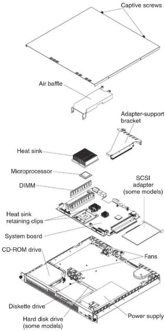
MajorcomponentsofthexSeries305Type8673
The following illustration shows the locations of major components in your server.
Note: The illustrations in this document might differ slightly from your hardware.
System-boardillustrations
This section provides illustrations of the system-board and the riser-card option connectors, internal cables, external ports, switches, jumpers, and LEDs.
System-boardandriser-cardoptionconnectors
The following illustration shows the location of the system-board connectors for user-installable options.

Note: Depending on the server model, the server might come with a SCSI adapter installed in PCI-X slot 2.
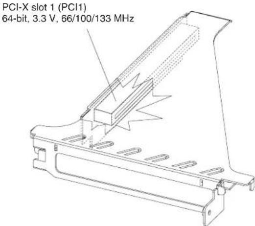
The following illustration shows the location of the PCI-X slot 1 connector on the riser card, which is attached to the adapter-support bracket.
System-boardinternalcableconnectors
The following illustration identifies the internal connectors on the system board.

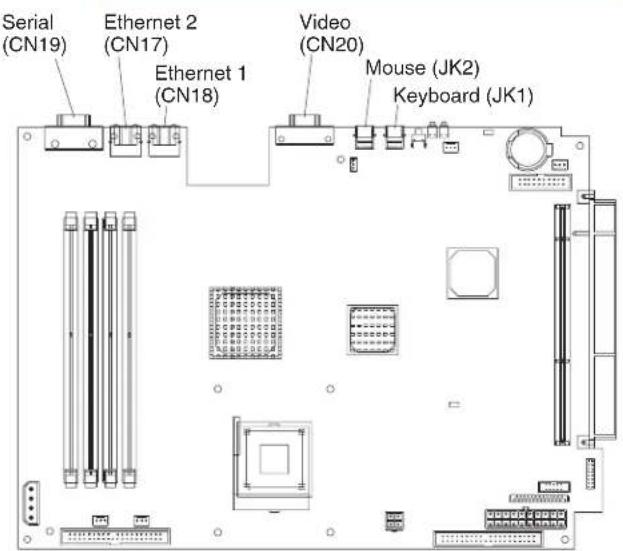
System-boardexternalportconnectors
The following illustration shows the location of the input/output external port connectors on the system board.
Note: The USB 1 and USB 2 ports are on the front of the server. For the location of the ports, see "Input/output ports and connectors" on page 45.
System-boardswitchesandjumpers
The following illustration identifies the switches and jumpers on the system board.
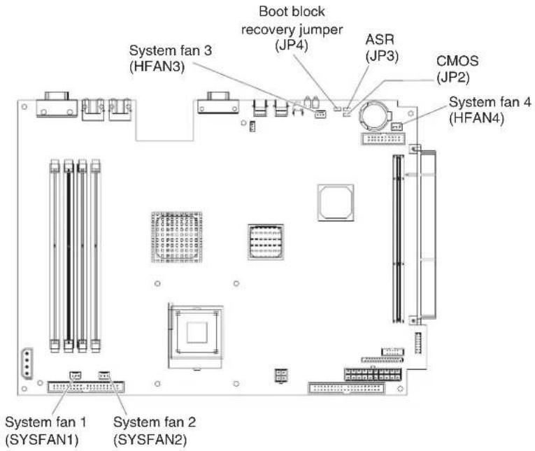
Notes:
-
The Automatic Server Restart (ASR) jumper (JP3) causes the server to restart automatically if it stops (for example, if the operating system stops running). The default position of the jumper (ASR enabled) is pins 2 and 3.
-
Jumper JP1 is not used.
System-boardLEDs
The following illustration shows the location of the LEDs on the system board.
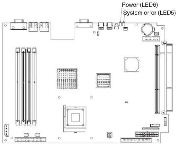
Removingthecover
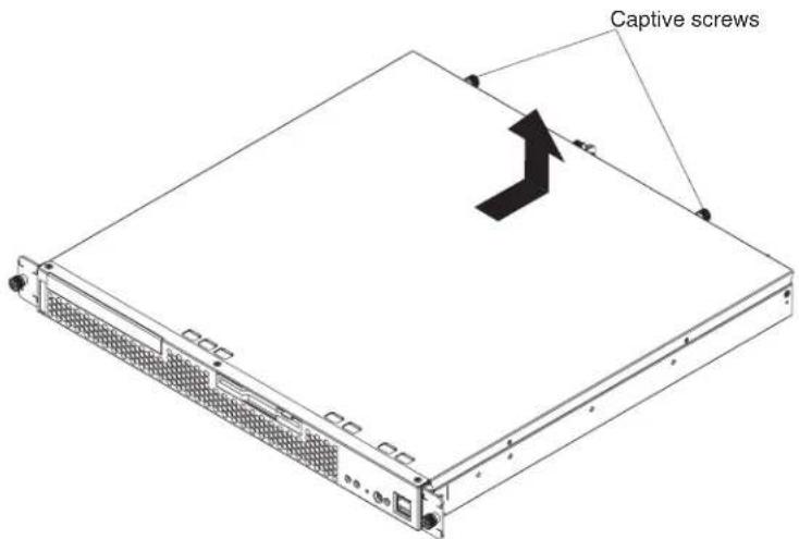
Complete the following steps to remove the server cover.
Note:
- Read "Safety information" on page 87.
- Read "Handling static-sensitive devices" on page 29.
- Turn off the server and peripheral devices.
- Disconnect the power cord; then, disconnect all external cables from the server.
- Loosen the two captive screws on the rear of the server.
- Slide the cover back, then up and off the server.
Attention: For proper cooling and airflow, replace the cover before turning on the server. Operating the server for extended periods of time (over 30 minutes) with the cover removed might damage server components.
Complete the following steps to remove the front bezel.
Note:
- Read "Safety information" on page 87.
-
Read "Handling static-sensitive devices" on page 29.
-
Turn off the server and peripheral devices.
- Disconnect the power cord; then, disconnect all external cables from the server.
- Remove the three screws from the top of the bezel.
- Pull the bezel away from the server front.
- Store the bezel in a safe place.
To replace the front bezel, reverse the previous steps.
Workingwithadapters
This section provides information about the expansion slots on the system board, and the peripheral component interconnect-extended (PCI-X) adapters. Your server comes with two peripheral component interconnect-extended (PCI-X) adapter slots. PCI-X slot 1 is located on the riser card that is attached to the adapter-support bracket. PCI-X slot 2 is located on the system board. You must first remove the adapter-support bracket to access the PCI-X slot 1 connector.
The following illustrations show the location of the PCI-X expansion slots on the system board and the riser card.
Note: The illustrations in this document might differ slightly from your hardware.

PCI-X slot 1 (PCI1)
64-bit, 3.3 V, 66/100/133 MHz
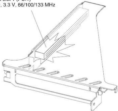
Note: When you install two 133 MHz controllers in the server, the maximum bus speed is 100 MHz.
Adapterconsiderations
Before you install adapters, review the following:
- Locate the documentation that comes with the adapter and follow those instructions in addition to the instructions in this chapter.
- If you need to change the switch settings or jumper settings on your adapter, follow the instructions that come with the adapter.
•There are two 64-bit, 66/100/133 MHz PCI-X slots.
- You can install one 64-bit one-half length full height adapter in expansion slot 1. You can install one low profile adapter in expansion slot 2.
-Your server supports 3.3 V or universal adapters.
- Your server uses a rotational interrupt technique to configure PCI-X adapters. You can use this technique to install PCI-X adapters that currently do not support sharing of PCI-X interrupts.
•The system scans PCI-X slots to assign system resources. By default the system starts (boots) the CD-ROM and diskette drives first. Then, the system scans PCI-X slot 2, PCI-X slot 1, and the integrated Ethernet.
- If the server is a SCSI model server, the server will have a SCSI adapter installed in PCI-X slot 2.
Note: You can use the Configuration/Setup Utility program to change the boot precedence for your server. Select StartOptions from the Configuration/Setup Utility program main menu.
Installinganadapter
Complete the following steps to install an adapter:
Attention: When you handle static-sensitive devices, take precautions to avoid damage from static electricity. For details on handling these devices, see "handling static-sensitive devices" on page 29.
- Review "Safety information" on page 87, and the "Installation guidelines" on page 29.
- Turn off the server and peripheral devices.
- Disconnect the power cord; then, disconnect all external cables from the server.
- Remove the server cover. See "Removing the cover" on page 34.
Attention: Before you install the adapter, route the adapter cables.
- Determine which PCI-X expansion slot you will use for the adapter.
Note: Check the instructions that come with the adapter for any requirements, restrictions, or cabling instructions. It might be easier for you to route cables before you install the adapter.
- Loosen the adapter slot captive screw.
a. If you are installing the adapter in PCI-X slot 1, loosen the captive screw that is near the video connector.
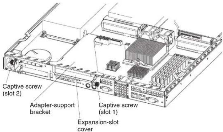
b. If you are installing the adapter in PCI-X slot 2, loosen the captive screw that is near the power cord connector.
- Remove the expansion-slot cover.
Attention:PCI expansion-slot cover must be installed on all vacant slots. This maintains the electronic emissions characteristics of the server and ensures proper cooling of server components.
- If you are installing the adapter in PCI-X slot 1, lift the adapter-support bracket from the server; then, remove the expansion-slot cover from the bracket. - If you are installing the adapter in PCI-X slot 2, lift the captive-screw bracket; then, remove the expansion-slot cover.
-
Touch the static-protective package containing the adapter to any unpainted metal surface on the server. Then, remove the adapter from the static-protective package. Avoid touching the components and gold-edge connectors on the adapter.
-
Place the adapter, component-side up, on a flat, static-protective surface and set any jumpers or switches as described by the adapter manufacturer, if necessary.
Attention: When you install an adapter in the server, be sure that it is completely and correctly seated in the PCI expansion slot before you turn on the server. Incomplete insertion might cause damage to the system board or the adapter.
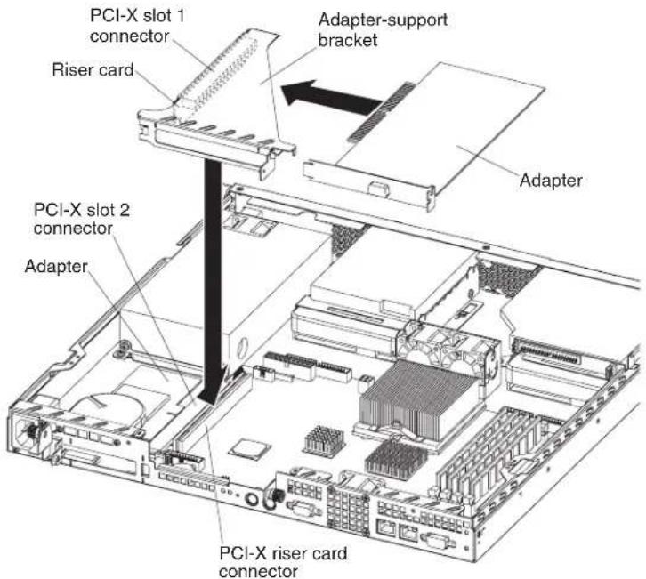
- To install the adapter, carefully grasp the adapter by its top edge or upper corners, and align it with the PCI-X expansion slot; then, press the adapter firmly into the expansion slot.
Note: When you install the adapter in PCI-X slot 2, you must slide the adapter underneath the system fan to properly align the adapter with the expansion-slot connector. Do not remove the system fan from the server.
-
If you installed an adapter in PCI-X slot 2, continue with the next step. If you removed the adapter-support bracket, reinstall it now. Make sure the riser card is fully seated into the riser card connector on the system board.
-
Tighten the captive screw on the rear of the server.
-
Connect required cables to the adapter.
-
If you have other options to install, do so now; otherwise, go to "Completing the installation" on page 42.
Harddiskdrives
The server comes with one integrated drive electronics (IDE) CD-ROM drive, one 1.44 MB diskette drive, and a hard disk drive (IDE or SCSI, depending on the server model).
Installingorreplacingaharddiskdrive
Complete the following steps to install or replace a hard disk drive:
Attention: When you handle static-sensitive devices, take precautions to avoid damage from static electricity. For details on handling these devices, see "handling static-sensitive devices" on page 29.
-
Inspect the new drive for any signs of damage.
-
Read "Safety information" on page 87 and the "Installation guidelines" on page 29.
-
Check the instructions that come with the drive for more information about installing your drive.
Notes:
a. If you are installing an IDE hard disk drive, you must set the drive to primary (master) or secondary (subordinate), depending on the configuration of your server. See the documentation that comes with the drive for instructions. b. If you are installing a SCSI hard disk drive, refer to the documentation that comes with your drive before installing it.
-
Turn off the server and peripheral devices. Disconnect the power cord; then, disconnect all external cables.
-
Remove the server cover. See "Removing the cover" on page 34.
-
Loosen the captive screw on the side of the drive cage.
Note: The illustrations in this document might differ slightly from your hardware.

-
Slide the drive cage away from the front of the server until the tabs on the chassis are in the unlocked position. Then, lift the drive cage out of the server.
-
Install the new hard disk drive:
a. Slide the hard disk drive into the bay in the drive cage.
b. Secure the drive to the drive cage using the screws that came with the option.
c. Slide the drive cage back into the server and tighten the captive screw.
d. Connect the signal cable and power cable to the rear of the drive. Ensure that the cables do not obstruct the fan behind the drive bay.
- If you have other options to install, do so now; otherwise, go to "Completing the installation" on page 42
InstallingDIMMs
Adding memory to your server is an easy way to make programs run faster. You can increase the amount of memory in your server by installing options that are called DIMMs. Your server uses a noninterleaved memory configuration.
Memory considerations:
- Your server comes with a DIMM installed on the system board in DIMM connector 4. When installing additional memory modules, install the second memory module in DIMM connector 3, the third in DIMM connector 2 and the fourth in DIMM connector 1. The DIMMs can be different sizes.
- Your xSeries 305 server supports 256 MB, 512 MB, and 1 GB DIMMS. Your server supports a maximum of 4 GB of system memory. See the ServerProven list at http://www.ibm.com/pc/compat for a list of memory modules for use with your server.
- The installing or removing of DIMMs changes the configuration information in the server. Therefore, you must change and save the new configuration information by using the Configuration/Setup Utility program. When you restart the server, the system displays a message indicating that the memory configuration has changed. Start the Configuration/Setup Utility program and select SaveSettings. See the User'sGuideon the IBM Documentation CD for more information about using the Configuration/Setup Utility program.
•The illustrations in this document might differ slightly from your hardware.
Complete the following steps to install a DIMM:
Attention: When you handle static-sensitive devices, take precautions to avoid damage from static electricity. For details on handling these devices, see “handling static-sensitive devices” on page 29.
- Read "Safety information" on page 8/ and the "Installation guidelines" on page 29.
- Turn off the server and peripheral devices. Disconnect the power cord; then, all external cables. Remove the cover see "Removing the cover" on page 34 for details).
- Touch the static-protective package containing the DIMM to any unpainted metal surface on the server. Then, remove the DIMM from the package.
- Install the DIMM:
a. Open the retaining clip on each end of the DIMM connector. Turn the DIMM so that the pins align correctly with the connector
Note: The illustrations in this document might differ slightly from your hardware.

Attention: To avoid breaking the retaining clips or damaging the DIMM connectors, open, and close the clips gently.
b. Insert the DIMM into the connector by aligning the DIMM edges with the slots at each end of the DIMM connector. Firmly press the DIMM straight down into the connector by applying pressure on both ends of the DIMM simultaneously. Be sure that the retaining clips snap into the locked position when the DIMM is firmly seated in the connector.
c. If a gap exists between the DIMM and the retaining clips, the DIMM has not been properly installed. In this case, open the retaining clips and remove the DIMM; then, reinsert the DIMM.
- If you have other options to install, do so now; otherwise, go to Completing the Installation.
Completingtheinstallation
To complete your installation, you must reinstall the server cover, connect all the cables, for certain options, run the Configuration/Setup Utility program. Follow the instructions in this section.
Attention: To maintain proper cooling and airflow, install the server cover before turning on the server. Operating the server for extended periods of time (over 30 minutes) with the server cover removed might damage server components.
Installingthecover
Complete the following steps to install the server cover:
- Install the cover by placing it into position and sliding it forward.
Attention: Before sliding the cover forward, make sure that the cover will engage the ledge at the front of the server properly.

- Tighten the captive screws to secure the cover as shown.
- Install the server in the rack. See the Rackinstallationinstructionsincluded with your server documentation for instructions.
- Connect the power cord and all external cables to the server, and then plug the power cord into a properly grounded electrical outlet.
Note: Your server has one keyboard connector on the back of the server. Use this connector to connect the server to a keyboard or optional console switch. You can also connect a USB keyboard to the server using one of the USB ports. After installing a USB keyboard, you might need to use the Configuration/Setup utility program to enable keyboardless operation and prevent the POST error message 301 from being displayed during startup. For detailed information about this option and how to connect it to your server, refer to the documentation that comes with the option.
Updatingyourserverconfiguration
When you start your server for the first time after you add or remove an internal option or an external SCSI device, you might see a message telling you that the configuration has changed. The Configuration/Setup Utility program automatically saves the new configuration information. See the User's Guide on the IBM xSeries DocumentationCD for information about the Configuration/Setup Utility program.
Some options have device drivers that you need to install. See the documentation that comes with your option for information about installing any required device drivers.
If your server has a RAID adapter installed and you have installed or removed a hard disk drive, see the documentation that comes with your RAID adapter for information about reconfiguring your disk arrays.
Replacingthebattery
When replacing the battery, you must replace it with a lithium battery of the same type from the same manufacturer. To avoid possible danger, read and follow the safety statement below.
To order replacement batteries, call 1-800-772-2227 within the United States, and 1-800-465-7999 or 1-800-465-6666 within Canada. Outside the U.S. and Canada, call your IBM reseller or IBM marketing representative.
Note: After you replace the battery, you must reconfigure your system and reset the system date and time.
Statement2:

CAUTION:
When replacing the lithium battery, use only IBMPartNumber33F8354oran equivalent type battery recommended by the manufacturer. If your system has a module containing alithium battery, replace it only with the samemodule typemade by the samemanufacturer. The battery contains lithium and can explode if not properly used, handled, or disposed of.
Donot:
- Throworimmerseintowater
•Heattomorethan100°C(212°F)
•Repairordisassemble
Disposeofthebatteryasrequiredbylocalordinancesorregulations.
Complete the following steps to replace the battery.
- Read "Safety information" on page 87, and follow any special handling and installation instructions supplied with the replacement battery.
- Turn off the server and peripheral devices. Disconnect the power cord and then, all external cables.
- Remove the cover. See "Removing the cover" on page 34.
- Remove the battery:
a. Press the battery release tab to release the battery from the socket.
b. Lift the battery out of the socket.

natural_image
Simple line drawing of a circular object with an arrow pointing right (no text or symbols)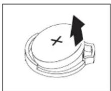
natural_image
Simple line drawing of a toilet with an arrow indicating rotation (no text or symbols)
natural_image
Simple line drawing of a mechanical component with a cross mark and arrow (no text or symbols)- Insert the new battery:
a. Tilt the battery so that you can insert it into the socket.
b. Press down on the battery after you insert it into the socket.

natural_image
Simple line drawing of a helmet with an arrow pointing to a circular base and a cross mark at the bottom (no text or symbols)
natural_image
Simple line drawing of a circular object with an arrow and cross mark, no text or symbols present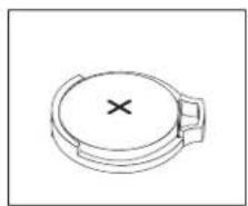
natural_image
Simple line drawing of a circular object with a cross mark on top, resembling a lid or cover (no text or symbols)- Reinstall the server cover, see "Installing the cover" on page 42.
- Reconnect the external cables and power cords; then, turn on the peripheral devices and the server.
- Start the Configuration/Setup Utility program and set configuration parameters.
- Set the system date and time and the power-on password.
•Reconfigure your server.
Input/outputportsandconnectors
Your server has the following I/O connectors on the front and rear of the server:
- Serial connector
•Universal Serial Bus (USB) connectors
•Keyboard connector
•Video connector
•Auxiliary-device (pointing device) connector
•Ethernet connectors


Serialport
Your server has one standard serial port. Some application programs require specific ports, and some modems function properly only at certain serial port addresses. Use the Configuration/Setup Utility program to change the port address assignments and prevent conflicts.
Viewingorchangingtheserial-portassignments
Complete the following steps to view or change the serial-port assignments:
- Restart the server and watch the monitor screen.
- When the message Press F1 for Configuration/Setup appears, press F1.
- From the main menu, select Devicesandl/OPorts; then, press Enter.
Note: The Devices and I/O Ports choice appears only on the full configuration menu. If you set two levels of passwords, you must enter the administrator password to access the full configuration menu.
- Select the serial port; then, use the arrow keys to advance through the settings available.
- Select SaveSettings; then, select ExitSetupto exit from the Configuration/Setup Utility main menu.
Serial-portconnector
Your server has one serial-port connector located on the rear of the server.
The following illustration shows the pin-number assignments for the 9-pin, male D-shell serial-port connector on the rear of your server. These pin-number assignments conform to the industry standard.
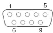
UniversalSerialBusports
Your server has two Universal Serial Bus (USB) ports, which configure automatically. USB is an emerging serial interface standard for telephony and multimedia devices. It uses Plug and Play technology to determine the type of device attached to the connector.
USBcablesandhubs
You need a 4-pin cable to connect devices to USB 1 or USB 2. If you plan to attach more than two USB devices, you must use a hub to connect the devices. The hub provides multiple connectors for attaching additional external USB devices.
USB technology provides up to 12 megabits-per-second (Mbps) speed with a maximum of 127 external devices and a maximum signal distance of five meters (16 ft). per segment.
USB-portconnectors
Each USB port has an external connector on the rear of the server for attaching USB-compatible devices.
The following illustration shows the pin-number assignments for the USB-port connectors on the rear of your server.

Keyboardconnector
There is one keyboard connector on the rear of the server.
Note: If you attach a standard keyboard to the keyboard connector, the USB ports, and devices will be disabled during the power-on self-test (POST).
The following illustration shows the pin-number assignments for the keyboard connector on the end of the cable.

Videoconnector
The following illustration shows the pin-number assignments for the 15-pin analog video connector on the rear of the server.
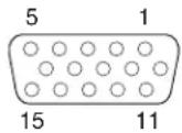
Auxiliary-device(pointingdevice)connector
There is one auxiliary-device connector that supports a mouse or other pointing device located on the rear of the server just under the keyboard connector.
The following illustration shows the pin-number assignments for the auxiliary-device connector on the end of the cable.

GigabitEthernetport
Your server comes with two integrated Gigabit Ethernet controllers. These controllers provide an interface for connecting to 10-Mbps, 100-Mbps, or 1000-Mbps networks and provide full-duplex (FDX) capability, which enables simultaneous transmission and reception of data on the Ethernet local area network (LAN).
To access the Ethernet port, connect a Category 3, 4, or 5 unshielded twisted-pair (UTP) cable to the RJ-45 connector on the rear of your server.
Note: The 100BASE-TX/1000BASE-T Fast Ethernet standard requires that the cabling in the network be Category 5 or higher.
The Ethernet (RJ-45) connector has two LEDs. The Ethernet link LED is on the right. When this green LED is on, there is an active connection on the Ethernet port. The Ethernet activity LED is on the left. When this green LED is on, there is activity between the server and the network. These LEDs have the same functions as the Ethernet link LED and the Ethernet activity LED on the rear of the server (see the User's Guide on the IBM xSeries Documentation CD for information about the Configuration/Setup Utility program).
ConfiguringtheGigabitEthernetcontroller
The Ethernet controllers are integrated on the system board. These controllers provide an interface for connecting to 10-Mbps, 100-Mbps, or 1000-Mbps networks
and provides full duplex (FDX) capability, which enables simultaneous transmission and reception of data on the Ethernet local area network (LAN). You do not need to set any jumpers or configure the controllers for your operating system before you use the Ethernet controllers. However, you must install a device driver to enable your operating system to address the Ethernet controllers. The device drivers are provided on the ServerGuide SetupandInstallationCD.
When you connect your server to the network, the Ethernet controller automatically detects the data-transfer rate (10 Mbps, 100 Mbps, or 1000 Mbps) on the network and then sets the controllers to operate at the appropriate rate. In addition, if the Ethernet ports that your server is connected to support auto-negotiation, the Gigabit Ethernet controllers will set the appropriate duplex state. That is, the Ethernet controllers will adjust to the network data rate, whether the data rate is standard Ethernet (10BASE-T), Fast Ethernet (100BASE-TX/1000BASE-T), half duplex (HDX), or full duplex (FDX). The controllers supports half-duplex (HDX) and full-duplex (FDX) modes at both speeds.
For information on configuring your Ethernet controller, see the Broadcom NetXtremeGigabitEthernetSoftwareCDthat comes with your server. For updated information about configuring your Ethernet controllers, go to the IBM Support Web site at http://www.ibm.com/pc/support and navigate to the area for your specific server type. From this area you can download documentation, the most current device drivers for your server, and software that supports advanced networking functions. After downloading, run the downloaded program launch.exe.
High-performanceEthernetmodes
Your Ethernet controllers support optional modes, such as teaming, priority packets, load balancing, fault tolerance, and virtual LANs, which provide higher performance, security, and throughput for your server. These modes apply to the integrated Ethernet controller and to the controllers on supported Ethernet adapters.
Ethernetportconnector
The following illustration shows the pin-number assignments for the RJ-45 port. These assignments apply to the 10BASE-T, 100BASE-TX, and 1000BASE-T devices.

Cablingtheserver
Notes:
- You must turn off the server before connecting any cables to or disconnecting any cables from the server.
-
See the documentation that comes with your options for additional cabling instructions. It might be easier for you to route cables before you install certain options.
-
Cable identifiers are printed on the cables that come with your server and options. Use these identifiers to connect the cables to the correct connectors. For example, the hard disk drive cables are labeled "HDD option."
Chapter5.RemovingandinstallingFRUs(serviceonly)
The following information describes how to remove and replace field replacable units (FRUs).
Important: These procedures are intended only for trained customer service representatives who are familiar with IBM xSeries products. See the parts listing in "Server" on page 80 to determine whether the component being replaced is a customer replaceable unit (CRU or a FRU. Field replaceable units must be replaced by qualified service personnel only.
Note:
- Read "Handling static-sensitive devices" on page 29
- Read "Safety information" on page 87.
Removingthecover

Complete the following steps to remove the server cover.
Note:
- Read "Handling static-sensitive devices" on page 29.
-
Read "Safety information" on page 87.
-
Turn off the server and peripheral devices.
- Disconnect the power cord; then, disconnect all external cables from the server.
- Loosen the two captive screws on the rear of the server.
- Slide the cover back, then up and off the server.
Attention: For proper cooling and airflow, replace the cover before turning on the server. Operating the server for extended periods of time (over 30 minutes) with the cover removed might damage server components.
Thermalgrease
This section contains information about removing and replacing the thermal grease between the heat sink and the microprocessor. The thermal grease must be replaced anytime the heat sink has been removed from the top of the microprocessor and is going to be reused, or when debris is found in the grease.
Note:
- Read "Installation guidelines" on page 29.
- Read the safety notices at "Safety information" on page 87.
- Read "Handling static-sensitive devices" on page 29.
Complete the following steps to replace damaged or contaminated thermal grease on the microprocessor and heat sink:
- Place the heat sink on a clean work surface.
- Remove the cleaning pad from its package and unfold it completely.
- Use the cleaning pad to wipe the thermal grease from the bottom of the heat sink.
Note: Be sure that all of the thermal grease is removed.
- Use a clean area of the cleaning pad to wipe the thermal grease from the microprocessor; then, dispose of the cleaning pad after all of the thermal grease is removed.

- Use the thermal grease syringe to place 16 uniformly spaced dots of 0.01ML each on the top of the microprocessor.

Note: 0.01ML is one tick mark on the syringe. If the grease is properly applied, approximately half (0.22ML) of the grease will remain in the syringe.
- Install the heat sink onto the microprocessor as described in "Removing and replacing a microprocessor" on page 53
Removingandreplacingamicroprocessor

Complete the following steps to remove a microprocessor.
Note:
- Read "Handling static-sensitive devices" on page 29 - Read "Safety information" on page 87.
-
Turn off the server and peripheral devices.
-
Disconnect the power cord; then, disconnect all external cables from the server.
-
Remove the server cover.
-
Grasp the air baffle; then, lift the air baffle from the server.
-
Remove the heat sink:
a. Loosen the screw on each of the two leaf springs on the retention module.
Note: Loosening one screw fully before loosening the other screw will help to break the thermal bond that adheres the heat sink to the microprocessor.
b. Pivot the leaf spring enclosure outward.
c. Gently twist the heat sink until you break the thermal bond, and pull the heat sink away from the retention module and the microprocessor.
-
Open the release lever of the microprocessor socket.
-
Pull the microprocessor out of the socket.
To install a microprocessor, reverse the previous steps.
Removing andreplacingtheretentionmodule
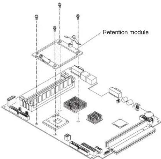
Complete the following steps to remove the retention module.
Note:
- Read "Handling static-sensitive devices" on page 29.
- Read "Safety information" on page 87.
- Turn off the server and peripheral devices.
- Disconnect the power cord; then, disconnect all external cables from the server.
- Remove the server cover.
- Grasp the air baffle; then, lift the air baffle from the server.
- Remove the heat sink:
a. Loosen the screw on each of the two leaf springs on the retention module.
Note: Loosening one screw fully before loosening the other screw will help to break the thermal bond that adheres the heat sink to the microprocessor.
b. Pivot the leaf spring enclosure outward.
c. Gently twist the heat sink until you break the thermal bond and pull the heat sink away from the retention module and the microprocessor.
- Loosen the four screws on the corners of the retention module and lift the retention module away from the system board.
To install a retention module, reverse the previous steps.
Removingandreplacingthesystemboard
Important: When replacing the system board, you must:
- Either update the firmware to the latest level, or restore the pre-existing firmware that the customer provides on a diskette or CD.
- Update the UUID (see "Updating the UUID" on page 26).
- Update the DMI/SMBIOS (see "Updating the DMI/SMBIOS data" on page 26).
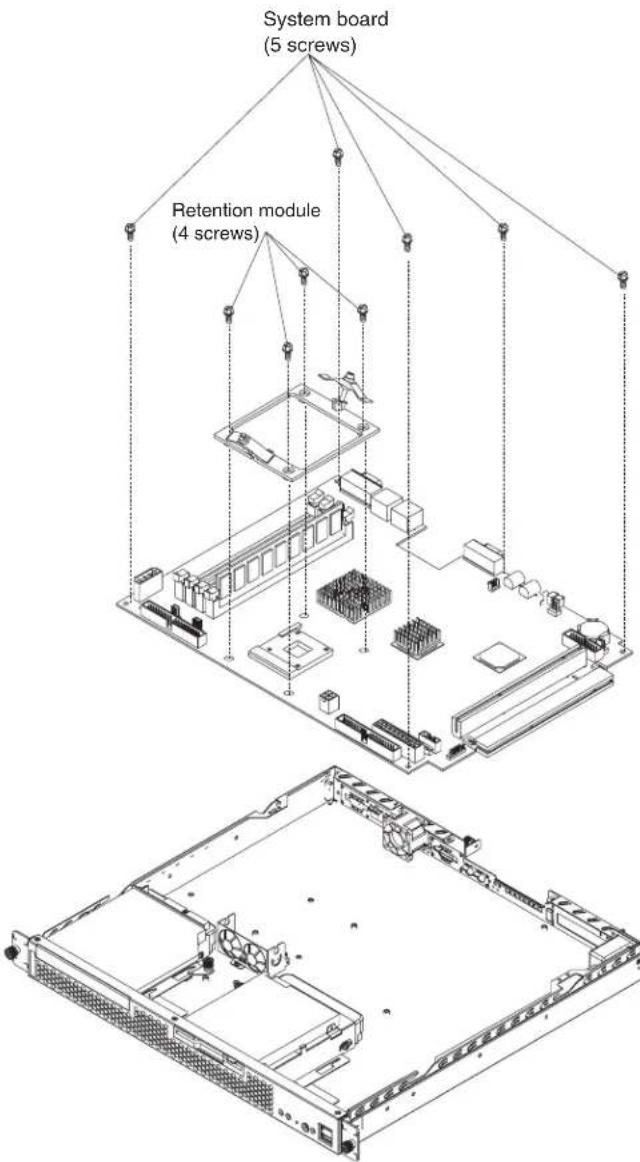
Complete the following steps to remove the system board.
Note:
- Read "Handling static-sensitive devices" on page 29.
-
Read "Safety information" on page 87.
-
Turn off the server and peripheral devices.
-
Disconnect the power cord; then, disconnect all external cables from the server.
-
Remove the server cover.
- Remove the air baffle.
- Remove all adapters and place them on a static-protective surface for reinstallation (see "Installing an adapter" on page 38).
- Remove all DIMMs and place them on a static-protective surface for reinstallation (see "Installing DIMMs" on page 41).
- Disconnect all cables from the system board.
- Remove the microprocessor and the retention module; and, place them on a static-protective surface for reinstallation (see 'Removing and replacing a microprocessor' on page 53 and 'Removing and replacing the retention module' on page 54).
- Remove the screws that secure the system board to the chassis, and put the screws in a safe place.
- Pull the system board carefully out of the chassis.
Complete the following steps to install a system board:
- Align the system board with the chassis and replace the screws that you removed in step 9 above.
- Replace all components, including the retention module and microprocessor, in the reverse order from which they were removed.
- Replace the cover. See "Installing the cover".
- Connect the external cables and power cords; then, turn on the peripheral devices and the server.
Removingandreplacingtheswitch/LED/USBcard

Complete the following steps to remove the Switch/LED/USB card.
Note:
- Read "Handling static-sensitive devices" on page 29.
-
Read "Safety information" on page 87.
-
Turn off the server and peripheral devices.
-
Disconnect the power cord; then, disconnect all external cables from the server.
-
Remove the server cover.
-
Remove the cables that surround the power supply and the switch/LED/USB card.
-
Remove the power supply (see "Removing and replacing a power supply" on page 57).
-
Loosen the two screws on the switch/LED/USB card and remove the card.
To install the Switch/LED/USB card, reverse the previous steps.
Removingandreplacingapowersupply

Complete the following steps to remove the power supply.
Note:
- Read "Handling static-sensitive devices" on page 29. - Read "Safety information" on page 87.
-
Turn off the server and peripheral devices.
-
Disconnect the power cord; then, disconnect all external cables from the server.
-
Remove the server cover.
-
Remove the cables near the power supply.
-
Remove the screws that secure the power supply to the chassis.
-
Lift the power supply away from the chassis.
-
Remove the screws that attach the power-supply connector to the back of the server; then, pull the connector out of the chassis.
To install the power supply, reverse the previous steps.
Complete the following steps to remove the front bezel.
Note:
- Read "Handling static-sensitive devices" on page 29.
- Read "Safety information" on page 87.
- Turn off the server and peripheral devices.
- Disconnect the power cord; then, disconnect all external cables from the server.
- Remove the three screws from the top of the bezel.
- Pull the bezel away from the server front.
- Store the bezel in a safe place.
To replace the front bezel, reverse the previous steps.
RemovingandreplacingthePCIrisercard
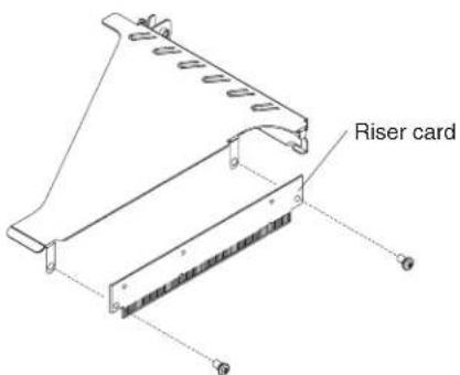
Complete the following steps to remove the PCI riser card.
Note:
- Read "Handling static-sensitive devices" on page 29.
- Read "Safety information" on page 87.
- Turn off the server and peripheral devices.
- Disconnect the power cord; then, disconnect all external cables from the server.
- Remove the server cover.
- Loosen the captive screw located adjacent to PCI-X slot 1 on the rear of the server.
- Remove the expansion-slot cover.
- Turn the expansion-slot cover until the PCI riser card is facing you.
- Remove the two screws from the PCI riser card.
- Gently pull the PCI riser card away from the expansion-slot cover.
To install a PCI riser card, reverse the previous steps.
Removingandreplacingthefans

Complete the following steps to remove the fan assembly.
Note:
- Read "Handling static-sensitive devices" on page 29.
- Read "Safety information" on page 87.
- Turn off the server and peripheral devices.
- Disconnect the power cord; then, disconnect all external cables from the server.
- Remove the server cover.
- Disconnect the fan cables from the system board.
- Lift fan 1 and fan 2 out of the fan cage and away from the server.
- Remove the two screws that secure fan 3 to the back of the server, and lift the fan away from the server.
Complete the following steps to install the fans.
- Orient the fans so that the airflow arrow on the side of each fan is facing or pointing toward the rear of the server
Note: Proper airflow is from the front of the server to the rear.
- Push fan 1 and fan 2 into the fan cage.
- Secure fan 3 to the back of the server with two screws.
- Replace the cover. See "Installing the cover".
- Connect the external cables and power cords; then, turn on the peripheral devices and the server.
Removingandreplacingtheblower

Complete the following steps to remove the blower.
Note:
- Read "Handling static-sensitive devices" on page 29
- Read "Safety information" on page 87.
- Turn off the server and peripheral devices.
- Disconnect the power cord; then, all disconnect external cables from the server.
- Remove the cover.
- Disconnect the blower cable from the system board.
- Remove the two screws that attach the blower to the back of the server.
- Gently pull the blower out and away from the server.
To install the blower, reverse the previous steps.
Removingandreplacingtheairbaffle
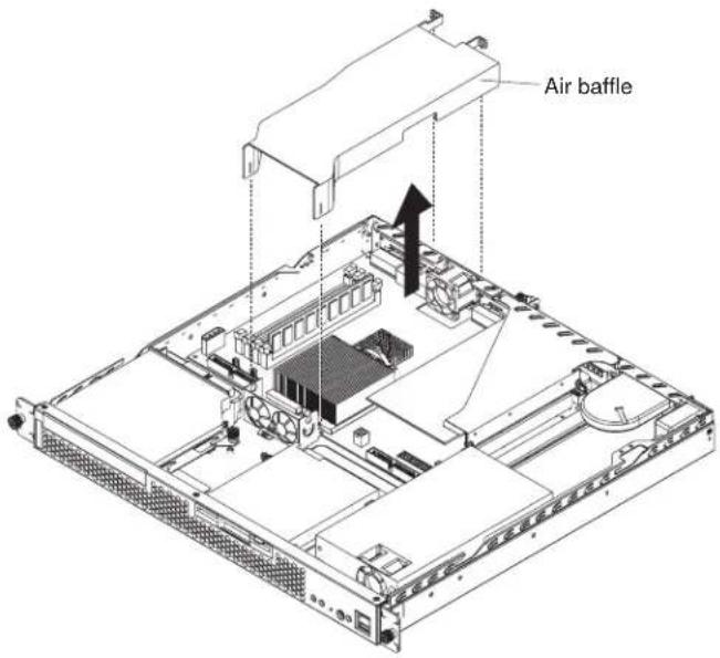
Complete the following steps to remove the air baffle.
Note:
- Read "Handling static-sensitive devices" on page 29.
- Read "Safety information" on page 87.
- Turn off the server and peripheral devices.
- Disconnect the power cord; then, disconnect all external cables from the server.
- Remove the server cover.
- Grasp the air baffle on each side and squeeze gently; then, pull the baffle up and away from the back of the chassis.
- When the baffle is free of the back of the chassis, lift it out of the server.
To install the air baffle, reverse the previous steps.
Chapter6.Symptom-to-FRUindex
This index supports xSeries 305 servers.
Notes:
- Check the configuration before you replace a FRU. Configuration problems can cause false errors and symptoms.
- For IBM devices not supported by this index, refer to the manual for that device.
- Always start with "General checkout" on page 17.
The symptom-to-FRU index lists symptoms, errors, and the possible causes. The most likely cause is listed first. Use this symptom-to-FRU index to help you decide which FRUs to have available when servicing the computer.
The first column of the two-column tables in this index lists error codes or messages, and the second column lists one or more suggested actions or FRUs to replace. Take the action (or replace the FRU) suggested first in the list of the second column, then try the server again to see if the problem has been corrected.
Note: Try reseating a suspected component or reconnecting a cable before replacing the component.
The POST BIOS code displays POST error codes and messages on the screen.
Beepsymptoms
Beep symptoms are short tones or a series of short tones separated by pauses (intervals without sound). See the following examples.
Note: One beep after successfully completing POST indicates the system is functioning properly.
| BeepsDescription | |
| 1-2-3 | One beepA pause (or break)Two beepsA pause (or break)Three Beeps |
| 4Four continuous beeps | |
| Beep/symptomFRU/action | |
| 1-1-2(processor register test failed) | 1. Optionalmicroprocessor(ifinstalled)2. Microprocessor |
| 1-1-3(CMOS write/read test failed) | 1. Battery2. System board |
| 1-1-4(BIOS EEPROM checksum failed) | •Systemboard |
| 1-2-1(Programmable interval timer failed) | •Systemboard |
| Beep/symptomFRU/action | |
| 1-2-2(DMA initialization failed) | •Systemboard |
| 1-2-3(DMA page register write/read failed) | •Systemboard |
| 1-2-4(RAM refresh verification failed) | 1. DIMM2. System board |
| 1-3-1(First 64K RAM test failed) | 1. DIMM2. Memory adapter |
| 1-3-2(First 64K RAM parity test failed) | 1. DIMM2. System board |
| 2-1-1(Secondary DMA register failed) | •Systemboard |
| 2-1-2(Primary DMA register failed) | •Systemboard |
| 2-1-3(Primary interrupt mask register failed) | •Systemboard |
| 2-1-4(Secondary interrupt mask register failed) | •Systemboard |
| 2-2-2(Keyboard controller failed) | 1. Keyboard2. System board |
| 2-2-3(CMOS power failure and checksum checks failed) | 1. Battery2. System board |
| 2-2-4(CMOS configuration information validation failed) | 1. Battery2. System board |
| 2-3-1(Screen initialization failed) | 1. JumperonJ182. System board |
| 2-3-2(Screen memory failed) | •Systemboard |
| 2-3-3(Screen retrace failed) | •Systemboard |
| 2-3-4(Search for video ROM failed) | •Systemboard |
| 2-4-1(Video failed) | •Systemboard |
| 3-1-1(Timer Tick Interrupt failed) | •Systemboard |
| 3-1-2(Interval timer channel 2 failed) | •Systemboard |
| 3-1-3(RAM test failed above address OFFFFH) | 1. DIMM2. System board |
| 3-1-4(Time of day clock failed) | 1. Battery2. System board |
| 3-2-1(Serial port failed) | •Systemboard |
| 3-2-2(Parallel port failed) | •Systemboard |
| 3-2-4(Failed comparing CMOS memory size against actual) | 1. DIMM2. System board3. Battery |
| 3-3-1(Memory size mismatch occurred) | 1. DIMM2. System board3. Battery |
| 3-3-2(Critical SMBUS error occurred (I2C bus error) | 1. Disconnectserverpower,wait30secondsandretry.2. System board.3. Microprocessor/PCI riser card.4. DIMMs.5. Hard disk drive backplane.6. Hard disk drive power cable. |
| 3-3-3(No optional memory in the system) | 1. Installorreseatthememorymodules.2. DIMMs.3. System board. |
Nobeepsymptoms
| NoBeepSymptomFRU/Action | |
| Nobeepandnovideo.(System attention LED is off) | •Systemboard |
| Nobeepandnovideo.(System attention LED is on) | •See“InformationpanelsystemerrorLED”. |
| Noacpower | 1. Checkthepowercord.2. Power supply. |
| Nobeepandnovideo | •See“Undeterminedproblems”onpage77. |
Diagnosticerrorcodes
Note: In the following error codes, if XXX is 000, 195, or 197, do not replace a FRU. The description for these error codes are:
000The test passed.
195The Esckey was pressed to abort the test.
197This is a warning error and may not indicate a hardware failure.
For all error codes, replace/follow the FRU/Action indicated.
| ErrorCode/SymptomFRU/Action | |
| 001-XXX-000(Failed core tests) | •System board |
| 001-XXX-001(Failed core tests) | •System board |
| 001-250-000(Failed System Board ECC) | •System board |
| 001-250-001(Failed System Board ECC) | •System board |
| 005-XXX-000(Failed Video test) | 1. Videoadapter(ifinstalled)2. System board |
| 011-XXX-000(Failed COM1 Serial Port test) | •System board |
| 011-XXX-001(Failed COM2 Serial Port test) | •System board |
| 014-XXX-000(Failed Parallel Port test) | •System board |
| 015-XXX-001(USB interface not found, board damaged) | •System board |
| 015-XXX-015(Failed USB External Loopback test) | 1. Makesureparallelportisnotdisabled.2. Re-run USB External Loopback test.3. System board. |
| 015-XXX-198(USB device connected during USB test) | 1. RemoveUSBdevicesfromUSB1andUSB2.2. Re-run test.3. System board. |
| 020-XXX-000(Failed PCI Interface test) | •System board |
| 030-XXX-000(Failed Internal SCSI interface test) | •System board |
| 030-XXX-00N(Failed SCSI test on PCI slot N. Check system error log before replacing a FRU.) | •Adapter in slot N |
| 035-XXX-099 | 1. Noadapterswerefound.2. If adapter is installed re-check connection. |
| 035-XXX-S99(Failed RAID test on PCI slot S. S = number of failing PCI slot. Check System Error Log before replacing a FRU.) | 1. Adapter2. Hard disk drive backplane3. Cable |
| 035-XXX-SNN(Check System Error Log before replacing a FRU. S = number of failing PCI slot; NN = SCSI ID of failing hard disk drive.) | •Hard disk drive with SCSI ID NN on RAID adapter in PCI slot S |
| 035-253-S99(RAID adapter initialization failure) | 1. ServeRAID Adapter in slot S is not configured properly. Obtain the basic and extended configuration status and refer to the ServeRAID Hardware Maintenance Manual for more information.2. Cable.3. Adapter. |
| 075-XXX-000(Failed Power Supply test) | •Power supply |
| 089-XXX-001(Failed Microprocessor test) | •Microprocessor |
| 180-XXX-003(Failed System Board LED test) | •Mouse |
| 201-XXX-0NN(Failed Memory test NN = DIMM location) | 1. DIMMlocation=NN2. Memory card |
| 201-XXX-999(Multiple DIMM failure, see error text.) | •See error text for failing DIMMs. |
| 202-XXX-001(Failed System Cache test) | •Microprocessor 1 |
| 206-XXX-000(Failed Diskette Drive test) | 1. Cable2. Diskette drive3. System board |
| 215-XXX-000(Failed IDE CD-ROM test) | 1. RerunthetestusingadifferentCD-ROM.2. CD-ROM drive cables.3. CD-ROM drive.4. System board. |
| 217-198-XXX(Could not establish drive parameters) | 1. Checkcableandtermination2. Hard disk drive backplane3. Hard disk drive |
| 217-XXX-000(Failed BIOS Fixed Disk test)Note:If RAID is configured, the fixed disk number refers to the RAID logical array. | •Harddiskdrive1 |
| 217-XXX-001(Failed BIOS Fixed Disk test)Note:If RAID is configured, the fixed disk number refers to the RAID logical array. | •Harddiskdrive2 |
| 217-XXX-002(Failed BIOS Fixed Disk test)Note:If RAID is configured, the fixed disk number refers to the RAID logical array. | •Harddiskdrive3 |
| 301-XXX-000(Failed Keyboard test) | •Keyboard |
| 302-XXX-000(Mouse failed) | •Mouse |
| 305-XXX-000(Video monitor failure) | 1. Videomonitor2. Video adapter |
| 405-XXX-000(Failed Ethernet test on controller on the System Board) | 1. VerifythatEthernetisnotdisabledinBIOS.2. System board. |
| 405-XXX-00N(Failed Ethernet test on adapter in PCI slot N) | 1. AdapterinPCIslotN2. System board |
| 415-XXX-000(Failed Modem test) | 1. Cable2. Modem3. System board |
Errorsymptoms
| GeneralFRU/Action | |
| CD-ROMtestfailed. | 1. CD-ROMdrive/harddiskdriveassembly2. System board |
| CMOSRAMtestfailed. | •Systemboard |
| DisketteDrivetestfailed. | 1. Diskettedrive2. Diskette drive cable3. System board |
| ECCControllerLogic. | •Systemboard |
| Ethernettestfailed. | •Systemboard |
| ExternalCachetestfailed. | •Microprocessor |
| Fixed-diskdrivetestfailed. | 1. Harddiskdrive2. Fixed-disk drive cable |
| IntegratedSPtestfailed. | •Systemboard |
| KeyboardControllertestfailed. | •Systemboard |
| Microprocessortestfailed. | •Microprocessor |
| Memorytestfailed. | 1. Memory2. System board |
| Parallelporttestfailed. | •Systemboard |
| PCItestfailed. | •Systemboard |
| RAMRefreshtestfailed. | •Systemboard |
| SCSlcontrollertestfailed. | •Systemboard |
| Serialporttestfailed. | •Systemboard |
| ServeRAIDtestfailed. | •RAIDcontrolleradapter |
| Systemmanagementtestfailed. | 1. Systemmanagementadapter,ifinstalled2. System board |
| Systemtimertestfailed. | •Systemboard |
| GeneralIFRU/Action | |
| TapeDrivetestfailed. | •Tapedrive |
| USBInterfacetestfailed. | •Systemboard |
| USBPorttestfailed. | •Systemboard |
| Videotestfailed. | •Systemboard |
| SetupAction | |
| SetupandInstallationCD won’tstart. | •Be sure the server is supported; all eServers with a startable (bootable) CD-ROM drive are supported.•If the startup (boot) sequence settings have been altered, be sure the CD-ROM is first in the boot sequence.•If more than one CD-ROM drive is installed, be sure that only one drive is set as the primary drive. Start the CD from the primary drive. |
| ServeRAIDprogramcannot viewallinstalleddrives-or -cannotinstallNOS. | •Be sure there are no duplicate SCSI IDs or IRQ assignments.•Be sure that the hard disk drive is connected properly. |
| TheOperatingSystem Installationprogram continuouslyloops. | Free up more space on the hard disk. |
| ServerGuidewon’tstart yourNOSCD. | Be sure the NOS CD you have is supported by ServerGuide. See the Setupand InstallationCD label for a list of NOS versions supported. |
| Can’tinstallNOS-optionis grayedout. | Either there is no logical drive defined (ServeRAID systems) or the ServerGuide system partition is not present. Run the setup and configuration program. |
| TechConnectCDAction | |
| Can’tstartTechConnect CD. | Be sure you’re starting the CD on a system with Microsoft Windows installed. |
| Can’tviewpublications fromTechConnectCD,or textisunreadable. | Be sure you have the Adobe reader installed (available from the TechConnect CD). |
| SystemUpdatesandApplicationsCD | Action |
| Get "time out" or "Unknown host"errors | Be sure you have access to the Internet through FTP directly. |
POSTerrorcodes
In the following error codes, Xcan be any number or letter.
| Note: See "Server" on page 80 to determine which components should be replaced by a field service technician. | |
| Errorcode/symptomFRU/action | |
| 062(Three consecutive boot failures using the default configuration.) | 1. RuntheConfiguration/SetupUtilityprogram.2. Battery.3. System board.4. Microprocessor. |
| 101,102,106(System and processor error) | •Systemboard |
| 114(Adapter read-only memory error) | 1. Rundiagnostics.2. Failing adapter. |
| 151(Real time clock error) | 1. Rundiagnostics.2. Battery.3. System board. |
| 161(Real time clock battery error) | 1. RuntheConfiguration/SetupUtilityprogram.2. Battery.3. System board. |
| 162(Device configuration error)Note:Be sure to load the default settings and any additional desired settings; then, savetheconfiguration. | 1. RuntheConfiguration/SetupUtilityprogram.2. Battery.3. Failing device.4. System board. |
| 163(Real-time clock error) | 1. RuntheConfiguration/SetupUtilityprogram.2. Battery.3. System board. |
| 164(Memory configuration changed.) | 1. RuntheConfiguration/SetupUtilityprogram.2. DIMM.3. System board. |
| 175(Hardware error) | •Systemboard |
| 176(Computer cover or cable cover was removed without a key being used) | 1. RuntheConfiguration/SetupUtilityprogram.2. System board. |
| 177,178(Security hardware error) | 1. RuntheConfiguration/SetupUtilityprogram.2. System board. |
| 184(Power-on password corrupted) | 1. RuntheConfiguration/SetupUtilityprogram.2. System board. |
| 185(Drive startup sequence information corrupted) | 1. RuntheConfiguration/SetupUtilityprogram.2. System board. |
| 186(Security hardware control logic failed) | 1. RuntheConfiguration/SetupUtilityprogram.2. System board. |
| 187(VPD serial number not set.) | 1. SetserialnumberintheConfiguration/SetupUtilityprogram.2. System board. |
| 188(Bad EEPROM CRC #2) | 1. RuntheConfiguration/SetupUtilityprogram.2. System board. |
| 189(Three attempts made to enter the system with invalid passwords) | 1. RuntheConfiguration/SetupUtilityprogram. |
| 201(Memory test error.) If the server does not have the latest level of BIOS installed, update the BIOS to the latest level and run the diagnostic program again. | 1. DIMM2. System board |
| 262(DRAM parity configuration error) | 1. RuntheConfiguration/SetupUtilityprogram.2. Battery.3. System board. |
| 289(DIMM has been disabled by user or the system) | 1. RuntheConfiguration/SetupUtilityprogram,iftheDIMMwas disabledbytheuser.2. Disabled DIMM, if not disabled by user.3. System board. |
| 301(Keyboard or keyboard controller error) | 1. Keyboard2. System board |
| 303(Keyboard controller error) | •Systemboard |
| 602(Invalid diskette boot record) | 1. Diskette2. Diskette drive3. Cable4. System board |
| 604(Diskette drive error) | 1. RuntheConfiguration/SetupUtilityprogramanddiagnostics.2. Diskette drive.3. Drive cable.4. System board. |
| 662(Diskette drive configuration error) | 1. RuntheConfiguration/SetupUtilityprogram.2. Diskette drive.3. Drive cable.4. System board. |
| 962(Parallel port configuration error) | 1. RuntheConfiguration/SetupUtilityprogram.2. System board. |
| 11XX(Serial port configuration error) | 1. RuntheConfiguration/SetupUtilityprogram.2. System board. |
| 1301(LED panel cable disconnected) | 1. LEDcableassembly.2. System board. |
| 1600(The service processor is not functioning) Complete the following steps before replacing a FRU:1. Ensure that a jumper is not installed on J28.2. Remove the ac power to the server, wait 20 seconds; then, reconnect the ac power. Wait 30 seconds; then, turn on the server. | 1. JumperonJ282. System board |
| 1601(Service processor failed to respond at the start of POST) | 1. Resettheserviceprocessor.2. Flash the service processor.3. System board. |
| 1762(Hard disk configuration error - IDE only) | 1. Harddiskdrive.2. Hard disk cables.3. Run the Configuration/Setup Utility program.4. System board. |
| 178X(Hard drive error - IDE only) | 1. Harddiskdrivecables2. Hard disk drive3. System board |
| 1800(No more hardware interrupt available for PCI adapter) | 1. RuntheConfiguration/SetupUtilityprogram.2. Remove adapter. |
| 1801(No more ROM space available for PCI adapter) | 1. RuntheConfiguration/SetupUtilityprogram.2. Remove adapter.3. Disable adapter BIOS and Run the Configuration/Setup Utility program. |
| 1962(Drive does not contain a valid boot sector) | 1. Verifythatastartableoperatingsystemisinstalled.2. Run the drive diagnostics.3. Hard disk drive.4. Hard disk drive backplane.5. Cable.6. System board. |
| 2400(Video controller test failure) | •Systemboard |
| 2462(Video memory configuration error) | •Systemboard |
| 5962(IDE CD-ROM drive configuration error) | 1. RuntheConfiguration/SetupUtilityprogram.2. CD-ROM drive.3. CD-ROM power cable.4. IDE cable.5. System board.6. Battery. |
| 8603(Pointing-device error) | 1. Pointingdevice2. System board |
| 00012000(Machine check architecture error) | 1. Microprocessor2. System board |
| 00019501(Microprocessor not functioning) | 1. Microprocessor2. System board |
| 00019701(Microprocessor failed BIST.) | 1. Microprocessor2. System board |
| 00180100(No room for PCI option ROM) | 1. RuntheConfiguration/SetupUtilityprogram.2. Adapter.3. System board. |
| 00180200(No more I/O space available for PCI adapter) | 1. RuntheConfiguration/SetupUtilityprogram.2. Failing adapter.3. System board. |
| 00180300(No more memory above 1MB for PCI adapter) | 1. RuntheConfiguration/SetupUtilityprogram.2. Failing adapter.3. System board. |
| 00180400(No more memory below 1MB for PCI adapter) | 1. RuntheConfiguration/SetupUtilityprogram.2. Failing adapter.3. System board. |
| 00180500(PCI option ROM checksum error) | 1. FailingPCladapter2. System board |
| 00180600(PCI device BIST failure) | 1. RuntheConfiguration/SetupUtilityprogram.2. Adapter.3. System board. |
| 00180700(PCI device not responding) | 1. Systemboard2. PCI adapter |
| 00180800(Unsupported PCI device installed) | 1. PCIeadapter2. System board |
| 00181000(General PCI error) | 1. PCIeadapter2. System board |
| 01295085(ECC checking hardware test error) | 1. Systemboard2. Microprocessor |
| I9990301(Fixed boot sector error) | 1. Harddiskdrivecable2. Hard disk drive backplane3. System board |
| I9990305(Fixed boot sector error, no operating system installed) | •Installanoperatingsystem. |
| I9990650(AC power has been restored) | 1. Checkpowerconnections.2. AC power cord. |
POST(ISPR)errorprocedures
Use the ISPR error procedures to help you solve ServeRAID problems. A complete list of error codes is listed at "ServeRAID error codes" on page 75.
Note: Where the ISPR Error Procedures refer to a Hard disk drive backplane, see the chapter of this publication that concerns service replaceable units.
EF10(Default ISPR)
- No ISPR error present.
9ZXX thru BZXX (SCSI bus error caused either by cables, termination, defective drives, etc.)
- Isolate between SCSI subsystem and controller by disconnecting all hard disk drive cables from suspect card, and reboot.
CAUTION:
DonotpressF5.Doingsochangestheserver'sconfiguration.
If an ISPR error is still present, perform the following actions until the error is no longer present:
a. Reseat the controller
b. Replace the controller
Notes:
a. SCSI channel cable details, if any, appear elsewhere in this publication.
b. The adapter/controller detects a configuration change. Do not choose Save Changes. Instead, press F10 to bypass any options to this effect.
2. If ISPR error is EF10 after disconnecting cables:
a. Identify which channel is causing the error by the second digit (Z) of the original ISPR code as indicated in the following table:
Note: ServeRAID-4H controllers have 4 channels; ServeRAID-4L and -4Lx controllers have only one channel; and ServeRAID-4M and -4Mx controllers have 2 channels. ServeRAID-5i controllers have no channels. The ServeRAID-5i uses the channel connectors of the server's onboard integrated SCSI controller.
Table4.SCSIdentifier
| SCSIChannelCode(z)Descriptions | |
| 1 Channel 1 | |
| 2 Channel 2 | |
| 3 Channel 1 & 2 | |
| 4 Channel 3 | |
| 5 Channel 1 & 3 | |
| 6 Channel 2 & 3 | |
| 7 Channel 1, 2, & 3 | |
| 8 Channel 4 | |
| 9 Channel 1 & 4 | |
| A Channel 2 & 4 | |
| B Channel 1, 2, & 4 | |
| C Channel 3 & 4 | |
| D Channel 1, 3, & 4 | |
| E Channel 2, 3, & 4 | |
| F Channel 1, 2, 3, & 4 |
b. Confirm that the channel(s) identified from the error in step 2a is (are) the cause of the error by verifying that the error presents itself only when the offending channel is reconnected.
c. Check termination of identified channel.
Note: SCSI channel termination details, if any, appear elsewhere in this publication.
d. Check for proper backplane jumper configuration.
Note: SCSI channel jumper details, if any, appear elsewhere in this publication.
e. Check for proper cabling configuration in systems that use hard disk drive status cables. Reconnect all cables removed in step 1 on page 73.
f. Disconnect one drive at a time attached to the channel identified in step 2a on page 74; then, reboot to determine which drive is causing the error.
g. Replace hard disk drive cable.
h. Replace hard disk drive backplane.
FFFForothercodenotlisted
-
Place download jumpers on the controller and try to flash the firmware code to the card.
-
Isolate between SCSI subsystem and controller by disconnecting all hard disk drive cables attached to the suspect card, and reboot.
CAUTION:
DonotpressF5.Doingsowillchangetheserver'sconfiguration.
If ISPR code is EF10 after disconnecting cables, follow the steps below until the error is eliminated:
a. Identify which channel is causing the error by reconnecting cables one at a time and rebooting until the error returns.
b. Check termination of identified channel in step 2a.
Note: SCSI channel termination details, if any, appear elsewhere in this publication.
c. Disconnect one drive at a time attached to channel identified in step 2a and reboot each time to determine which drive is causing the problem.
d. Replace hard disk drive cable attached to channel identified in step 2a.
e. Replace backplane attached to channel identified in step 2a.
- If original ISPR code is still present after disconnecting all hard disk drive cables and rebooting, perform the following actions until the error is no longer present:
- Reseat the controller
-Replace the controller
ServeRAIDerrorcodes
In the following error codes, xcan be any number or letter.
| Note: See “Server” on page 80 to determine which components should be replaced by a field service technician. | |
| Errorcode/symptomFRU/action | |
| 1xxx(Microcode checksum error) | •ServeRAID controller |
| 2xxx(Code DRAM error) | 1. Install download jumpers, flash latest level BIOS and firmware for controller. Remove jumpers.2. ServeRAID controller. |
| 3000-31XX(Code DRAM error) | 1. Install download jumpers, flash latest level BIOS and firmware for controller. Remove jumpers.2. ServeRAID controller. |
| 3200 (Code DRAM error) | 1. Install download jumpers, flash latest level BIOS code and firmware for controller. Remove jumpers.2. ServeRAID controller. |
| 3300 (ServeRAID-5i only) | 1. Install ServeRAID-5i controller in an extended PCI option slot. See the documentation that came with the server for more information. |
| 3E20 (ServeRAID-5i only) | 1. Remove the ServeRAID-5i controller from its slot and install it in the proper PCI option slot.2. Verify that the ServeRAID-5i controller is supported in this server.3. ServeRAID-5i controller.4. System board. |
| 3E2x | 1. Reseat the ServeRAID controller.2. Flash latest level of BIOS code and firmware for controller.3. ServeRAID-5i controller.4. Integrated RAID controller on server). |
| 4xxxthru 5xxx(Code DRAM error) | 1. Install download jumpers, flash latest level BIOS code and firmware for controller; then, remove jumpers.2. ServeRAID controller. |
| 6xxx(Cache DRAM error) (ServeRAID-4H only) | 1. Reseat daughter card.2. Install download jumpers, flash latest level BIOS code and firmware for controller; then, remove jumpers.3. ServeRAID controller. |
| 7xxxthru 8xxx(Host/local PCI bus interface error) | 1. Flash latest level of BIOS code and firmware for controller.2. If ServeRAID-4x controller, replace controller.3. If ServeRAID-5i controller, integrated RAID controller on the server. |
| 9003 | 1. Flash latest level of BIOS code and firmware for controller.2. Confirm that this controller is a supported option for this system.3. ServeRAID controller.4. Integrated RAID controller on the server). |
| 9xxxthru BZxx(SCSI bus error caused by cables, termination, defective drives, etc.). Zrefers to the specific channel or channels that cause the error. | 1. Follow indications at “POST (ISPR) error procedures” on page 73. Follow those instructions before continuing with the next steps listed in this index.2. Hard disk drive cable.3. Hard disk drive backplane.4. Hard disk drive.5. ServeRAID controller. |
| EFFE (Firmware code corrupt or download jumpers are in place) | 1. Flash latest level BIOS and firmware for controller; then,remove jumpers.2. ServeRAID controller. |
| FFFF or other code not listed | 1. Follow indications at “POST (ISPR) error procedures” on page 73.2. Hard disk drive cable.3. Hard disk drive backplane.4. Hard disk drive.5. ServeRAID controller. |
Undeterminedproblems
You are here because the diagnostic tests did not identify the failure, the Devices List is incorrect, or the system is inoperative.
Note: A corrupt CMOS can cause undetermined problems.
If power problems are suspected:
- Turn off the computer.
-
Be sure the system is cabled correctly.
-
Remove or disconnect the following (one at a time) until you find the failure (power-on the computer and reconfigure each time).
•Any external devices
•Modem, printer, mouse, or non-IBM devices
•Each adapter
•Drives
• Memory modules (minimum requirement = one 128 MB DIMM)
Note: Minimum operating requirements are:
a. 1 Power Supply
b. System board
c. 1 Microprocessor
d. 1 Terminator card in Slot 2
e. 1 Memory module (minimum of 1 DIMM in slot labeled DIMM 1)
- Power-on the computer. If the problem remains, suspect the following FRUs in the order listed:
•Power supply
- System board
Notes:
-
If the problem goes away when you remove an adapter from the system, and replacing that adapter does not correct the problem, suspect the system board, then the power supply.
-
If you suspect a networking problem and all the system tests pass, suspect a network cabling problem external to the system.
Chapter7.PartslistingxSeries305Type8673
This parts listing supports the xSeries 305 Type 8673.

Server
Note: Field replaceable units (FRUs) must be serviced only by qualified field service technicians. Customer replaceable units (CRUs) can be replaced by the customer.
IndexServer(xSeries305, Type8673)Models11x, 12x, 13x, 21x, 22x, 23x, 92x)
FRUNo.CRU/FRU
| 1 Air baffle (all models) 49P2767 CRU | |||
| 2 PCI riser card (all models) 49P2745 FRU | |||
| 3 Blower (all models) 49P2759 FRU | |||
| 4 System board (all models) 32P1399 FRU | |||
| 5 Chassis (all models) 49P2740 FRU | |||
| 6 Power supply, 200 watt (all models) 49P2742 FRU | |||
| 7 LED USB card (all models) 49P2755 FRU | |||
| 8 Front bezel assembly (all models) 49P2761 CRU | |||
| 9 Fan assembly, 40 mm (all models) | 49P2757 CRU | ||
| 10 | Memory, 256 PC 2100 ECC (all models) | 09N4306 CRU | |
| 11 | Microprocessor, 2.0 GHz (models 11x, 12x, 13x) | 49P2723 | FRU |
| 11 | Microprocessor, 2.2 GHz (models 21x, 22x, 23x) | 49P2727 | FRU |
| 11 | Microprocessor, 1.8 GHz (model 92x)) | 49P2803 | FRU |
| 12 | Heat sink, microprocessor | 49P2725 FRU | |
| 4 post rails (all models) | 49P2747 FRU | ||
| Alcohol wipe kit (all models) | 59P4739 FRU | ||
| Battery, 3.0 volt lithium | 33F8354 | FRU | |
| Cable management arm | 01R0890 CRU | ||
| Cable, diskette drive (all models) | 49P2736 CRU | ||
| Cable, IDE 1-drop (all models) | 49P2732 CRU | ||
| Cable, IDE 2-drop (all models) | 49P2774 CRU | ||
| Cable, SCSI signal (all models) | 49P2734 CRU | ||
| Cable, USB front assembly (all models) | 49P2753 FRU | ||
| Cable, switch LED (all models) | 49P2782 FRU | ||
| Cable, hard disk drive and CD-ROM (all models) | 49P2751 CRU | ||
| CD-ROM adapter (all models) | 49P2738 CRU | ||
| CD-ROM drive, 24X, primary (all models) | 06P5263 CRU | ||
| CD-ROM drive, 24X, alternate (all models) | 33P3231 CRU | ||
| Diskette drive, 12.7 black (all models) | 36L8645 CRU | ||
| Hard disk drive, 18.2 GB SCSI (models 13x, 23x) | 06P5365 CRU | ||
| Hard disk drive, 40. GB IDE (models 12x, 22x, 92x) | 19K1568 CRU | ||
| Jumper, 2.0 m (all models) | 36L8886 | FRU | |
| IndexServer(xSeries305,Type8673)Models11x,12x,13x,21x,22x, 23x,92x) | FRUNo.CRU/FRU |
| Miscellaneous parts kit (all models) | 49P2771 FRU |
| •Bezel, blank (1) | |
| •Bezel, diskette drive blank (1) | |
| •Bezel, PCI blank (2) | |
| •Heat sink (1) | |
| •Screw, M 3x4 flat (4) | |
| •Screw, M 3x5 pan (10) | |
| •Screw, M 3.5x6 (4) | |
| •Screw, M 3.5 steel (6) | |
| •Screw, M 3x5 slotted (2) | |
| •Screw, M 4x10 flat (2) | |
| •Screw, M 4x5 pan (4) | |
| •Spring, CD (2) | |
| •Spring, diskette drive (2) | |
| Power cord; see "Power cords" on page 82 (all models) CRU | |
| SCSI adapter (models 13x, 23x) 06P2215 CRU | |
| System service label (all models) 49P2769 FRU | |
| Thermal grease kit (all models) 59P4740 FRU | |
KeyboardCRUs
KeyboardCRUNo.
US English 37L2551
French Canadian 37L2552
LA Spanish 37L2553
| Arabic | 37L2555 |
| Belgium/French | 37L2556 |
| Belgium/UK | 37L2557 |
| Bulgarian | 37L2558 |
| Czech | 37L2559 |
| Danish | 37L2560 |
| Dutch | 37L2561 |
| French | 37L2562 |
| German | 37L2563 |
| Greek | 37L2564 |
| Hebrew | 37L2565 |
| Hungarian | 37L2566 |
| Korean | 02K0901 |
| Iceland | 37L2567 |
| Italy | 37L2568 |
| Norwegian | 37L2569 |
| Polish | 37L2570 |
| Portuguese 37L2571 | |
| Romanian | 37L2572 |
| Russian | 37L2573 |
| Serbian/Cyrillic | 37L2574 |
| Slavic | 37L2575 |
| Spanish | 37L2576 |
| Swedish/Finnish | 37L2577 |
| Swiss, French/German | 37L2578 |
KeyboardCRUNo.
Turkish 37L2579
Turkish 37L2580
UK English 37L2581
Yugosl/Lat 37L2582
US English-EMEA 37L2583
Chinese/US 37L2585
Thailand 37L2587
French Canadian 37L0913
Powercords
For your safety, IBM provides a power cord with a grounded attachment plug to use with this IBM product. To avoid electrical shock, always use the power cord and plug with a properly grounded outlet.
IBM power cords used in the United States and Canada are listed by Underwriter's Laboratories (UL) and certified by the Canadian Standards Association (CSA).
For units intended to be operated at 115 volts: Use a UL-listed and CSA-certified cord set consisting of a minimum 18 AWG, Type SVT or SJT, three-conductor cord, a maximum of 15 feet in length and a parallel blade, grounding-type attachment plug rated 15 amperes, 125 volts.
For units intended to be operated at 230 volts (U.S. use): Use a UL-listed and CSA-certified cord set consisting of a minimum 18 AWG, Type SVT or SJT, three-conductor cord, a maximum of 15 feet in length and a tandem blade, grounding-type attachment plug rated 15 amperes, 250 volts.
For units intended to be operated at 230 volts (outside the U.S.): Use a cord set with a grounding-type attachment plug. The cord set should have the appropriate safety approvals for the country in which the equipment will be installed.
IBM power cords for a specific country or region are usually available only in that country or region.
| IBMpowercordpart number | Usedinthesecountriesandregions |
| 13F9940 Argentina, Australia | Alalia, China (PRC), New Zealand, Papua New Guinea, Paraguay, Uruguay, Western Samoa |
| 13F9979 | Afghanistan, Algeria, Andorra, Angola, Austria, Belgium, Benin, Bulgaria, Burkina Faso, Burundi, Cameroon, Central African Rep., Chad, China (Macau S.A.R.), Czech Republic, Egypt, Finland, France, French Guiana, Germany, Greece, Guinea, Hungary, Iceland, Indonesia, Iran, Ivory Coast, Jordan, Lebanon, Luxembourg, Malagasy, Mali, Martinique, Mauritania, Mauritius, Monaco, Morocco, Mozambique, Netherlands, New Caledonia, Niger, Norway, Poland, Portugal, Romania, Senegal, Slovakia, Spain, Sudan, Sweden, Syria, Togo, Tunisia, Turkey, former USSR, Vietnam, former Yugoslavia, Zaire, Zimbabwe |
| 13F9997 Denmark | |
| 14F0015 Bangladesh, Burma | Pakistan, South Africa, Sri Lanka |
| 14F0033 Antigua, Bahrain | Brunei, Channel Islands, China (Hong Kong S.A.R.), Cyprus, Dubai, Fiji, Ghana, India, Iraq, Ireland, Kenya, Kuwait, Malawi, Malaysia, Malta, Nepal, Nigeria, Polynesia, Qatar, Sierra Leone, Singapore, Tanzania, Uganda, United Kingdom, Yemen, Zambia |
| 14F0051 Liechtenstein, Switzerland | |
| 14F0069 Chile, Ethiopia | Italy, Libya, Somalia |
| 14F0087 Israel | |
| 1838574 Thailand | |
| 6952300 Bahamas, Barbados | Bermuda, Bolivia, Brazil, Canada, Cayman Islands, Colombia, Costa Rica, Dominican Republic, Ecuador, El Salvador, Guatemala, Guyana, Haiti, Honduras, Jamaica, Japan, Korea (South), Liberia, Mexico, Netherlands Antilles, Nicaragua, Panama, Peru, Philippines, Saudi Arabia, Suriname, Taiwan, Trinidad (West Indies), United States of America, Venezuela |
AppendixA.Gettinghelpandtechnicalassistance
If you need help, service, or technical assistance or just want more information about IBM products, you will find a wide variety of sources available from IBM to assist you. This appendix contains information about where to go for additional information about IBM and IBM products, what to do if you experience a problem with your xSeries or IntelliStation ® system, and whom to call for service, if it is necessary.
Beforeyoucall
Before you call, make sure that you have taken these steps to try to solve the problem yourself:
- Check all cables to make sure that they are connected.
- Check the power switches to make sure that the system is turned on.
- Use the troubleshooting information in your system documentation, and use the diagnostic tools that come with your system.
- Go to the IBM Support Web site at http://www.ibm.com/pc/support/ to check for technical information, hints, tips, and new device drivers.
- Use an IBM discussion forum on the IBM Web site to ask questions.
You can solve many problems without outside assistance by following the troubleshooting procedures that IBM provides in the online help or in the publications that are provided with your system and software. The information that comes with your system also describes the diagnostic tests that you can perform. Most xSeries and IntelliStation systems, operating systems, and programs come with information that contains troubleshooting procedures and explanations of error messages and error codes. If you suspect a software problem, see the information for the operating system or program.
Usingthedocumentation
Information about your IBM xSeries or IntelliStation system and preinstalled software, if any, is available in the documentation that comes with your system. That documentation includes printed books, online books, README files, and help files. See the troubleshooting information in your system documentation for instructions for using the diagnostic programs. The troubleshooting information or the diagnostic programs might tell you that you need additional or updated device drivers or other software. IBM maintains pages on the World Wide Web where you can get the latest technical information and download device drivers and updates. To access these pages, go to http://www.ibm.com/pc/support/ and follow the instructions. Also, you can order publications through the IBM Publications Ordering System at www.elink.ibmlink.ibm.com/public/applications/publications/cgibin/pbi.cgi.
GettinghelpandinformationfromtheWorldWideWeb
On the World Wide Web, the IBM Web site has up-to-date information about IBM xSeries and IntelliStation products, services, and support. The address for IBM xSeries information is http://www.ibm.com/eserver/xseries/. The address for IBM IntelliStation information is http://www.ibm.com/pc/intellistation/.
You can find service information for your IBM products, including supported options, at http://www.ibm.com/pc/support/. If you click Profilefrom the support page, you
can create a customized support page. The support page has many sources of information and ways for you to solve problems, including:
•Diagnosing problems, using the IBM Online Assistant
- Downloading the latest device drivers and updates for your products
•Viewing Frequently Asked Questions (FAQ)
- Viewing hints and tips to help you solve problems
•Participating in IBM discussion forums
- Setting up e-mail notification of technical updates about your products
Softwareserviceandsupport
Through IBM Support Line, you can get telephone assistance, for a fee, with usage, configuration, and software problems with xSeries servers, IntelliStation workstations, and appliances. For information about which products are supported by Support Line in your country or region, go to http://www.ibm.com/services/sl/products/.
For more information about Support Line and other IBM services, go to http://www.ibm.com/services/, or go to http://www.ibm.com/planetwide/ for support telephone numbers.
Hardwareserviceandsupport
You can receive hardware service through IBM Integrated Technology Services or through your IBM reseller, if your reseller is authorized by IBM to provide warranty service. Go to http://www.ibm.com/planetwide/ for support telephone numbers.
In the U.S. and Canada, hardware service and support is available 24 hours a day, 7 days a week. In the U.K., these services are available Monday through Friday, from 9 a.m. to 6 p.m.
AppendixB.Relatedserviceinformation
Note: The service procedures are designed to help you isolate problems. They are written with the assumption that you have model-specific training on all computers, or that are familiar with the computers, functions, terminology, and service information provided in this manual.
Safetyinformation
The following section contains the safety information that you need to be familiar with before servicing an IBM computer.
Generalsafety
Follow these rules to ensure general safety:
- Observe good housekeeping in the area of the machines during and after maintenance.
- When lifting any heavy object:
- Ensure you can stand safely without slipping.
- Distribute the weight of the object equally between your feet.
- Use a slow lifting force. Never move suddenly or twist when you attempt to lift.
- Lift by standing or by pushing up with your leg muscles; this action removes the strain from the muscles in your back. Donotattempttoliftanyobjects thatweighmorethan16kg(35lb)orobjectsthatyouthinkaretooheavyfor you.
- Do not perform any action that causes hazards to the customer, or that makes the equipment unsafe.
- Before you start the machine, ensure that other service representatives and the customer's personnel are not in a hazardous position.
- Place removed covers and other parts in a safe place, away from all personnel, while you are servicing the machine.
- Keep your tool case away from walk areas so that other people will not trip over it.
- Do not wear loose clothing that can be trapped in the moving parts of a machine. Ensure that your sleeves are fastened or rolled up above your elbows. If your hair is long, fasten it.
- Insert the ends of your necktie or scarf inside clothing or fasten it with a nonconductive clip, approximately 8 centimeters (3 inches) from the end.
- Do not wear jewelry, chains, metal-frame eyeglasses, or metal fasteners for your clothing.
Remember: Metal objects are good electrical conductors.
- Wear safety glasses when you are: hammering, drilling soldering, cutting wire, attaching springs, using solvents, or working in any other conditions that might be hazardous to your eyes.
•After service, reinstall all safety shields, guards, labels, and ground wires. Replace any safety device that is worn or defective.
- Reinstall all covers correctly before returning the machine to the customer.
Electricalsafety

CAUTION:
Electricalcurrentfrompower,telephone,andcommunicationcablescanbe hazardous.Toavoidpersonalinjuryorequipmentdamage,disconnectthe attachedpowercords,telecommunicationsystems,networks,andmodems beforeyouopentheservercovers,unlessinstructedotherwiseinthe installationandconfigurationprocedures.
Observe the following rules when working on electrical equipment.
Important: Use only approved tools and test equipment. Some hand tools have handles covered with a soft material that does not insulate you when working with live electrical currents.
Many customers have, near their equipment, rubber floor mats that contain small conductive fibers to decrease electrostatic discharges. Do not use this type of mat to protect yourself from electrical shock.
- Find the room emergency power-off (EPO) switch, disconnecting switch, or electrical outlet. If an electrical accident occurs, you can then operate the switch or unplug the power cord quickly.
- Do not work alone under hazardous conditions or near equipment that has hazardous voltages.
-
Disconnect all power before:
-
Performing a mechanical inspection
– Working near power supplies -
Removing or installing main units
-
Before you start to work on the machine, unplug the power cord. If you cannot unplug it, ask the customer to power-off the wall box that supplies power to the machine and to lock the wall box in the off position.
- If you need to work on a machine that has exposed electrical circuits, observe the following precautions:
- Ensure that another person, familiar with the power-off controls, is near you.
Remember: Another person must be there to switch off the power, if necessary.
- Use only one hand when working with powered-on electrical equipment; keep the other hand in your pocket or behind your back.
Remember: There must be a complete circuit to cause electrical shock. By observing the above rule, you may prevent a current from passing through your body.
- When using testers, set the controls correctly and use the approved probe leads and accessories for that tester.
- Stand on suitable rubber mats (obtained locally, if necessary) to insulate you from grounds such as metal floor strips and machine frames.
Observe the special safety precautions when you work with very high voltages; these instructions are in the safety sections of maintenance information. Use extreme care when measuring high voltages.
- Regularly inspect and maintain your electrical hand tools for safe operational condition.
- Do not use worn or broken tools and testers.
- Never assume that power has been disconnected from a circuit. First, check that it has been powered-off.
•Always look carefully for possible hazards in your work area. Examples of these hazards are moist floors, nongrounded power extension cables, power surges, and missing safety grounds.
- Do not touch live electrical circuits with the reflective surface of a plastic dental mirror. The surface is conductive; such touching can cause personal injury and machine damage.
- Do not service the following parts with the power on when they are removed from their normal operating places in a machine:
– Power supply units
- Pumps
- Blowers and fans
- Motor generators
and similar units. (This practice ensures correct grounding of the units.)
• If an electrical accident occurs:
- Use caution; do not become a victim yourself.
- Switch off power.
– Send another person to get medical aid.
Safetyinspectionguide
The intent of this inspection guide is to assist you in identifying potentially unsafe conditions on these products. Each machine, as it was designed and built, had required safety items installed to protect users and service personnel from injury. This guide addresses only those items. However, good judgment should be used to identify potential safety hazards due to attachment of non-IBM features or options not covered by this inspection guide.
If any unsafe conditions are present, you must determine how serious the apparent hazard could be and whether you can continue without first correcting the problem.
Consider these conditions and the safety hazards they present:
- Electrical hazards, especially primary power (primary voltage on the frame can cause serious or fatal electrical shock).
- Explosive hazards, such as a damaged CRT face or bulging capacitor
- Mechanical hazards, such as loose or missing hardware
The guide consists of a series of steps presented in a checklist. Begin the checks with the power off, and the power cord disconnected.
Checklist:
- Check exterior covers for damage (loose, broken, or sharp edges).
- Turn off the computer. Disconnect the power cord.
- Check the power cord for:
a. A third-wire ground connector in good condition. Use a meter to measure third-wire ground continuity for 0.1 ohm or less between the external ground pin and frame ground.
b. The power cord should be the appropriate type as specified in the parts listings.
c. Insulation must not be frayed or worn.
-
Remove the cover.
-
Check for any obvious non-IBM alterations. Use good judgment as to the safety of any non-IBM alterations.
-
Check inside the unit for any obvious unsafe conditions, such as metal filings, contamination, water or other liquids, or signs of fire or smoke damage.
-
Check for worn, frayed, or pinched cables.
-
Check that the power-supply cover fasteners (screws or rivets) have not been removed or tampered with.
Handlingelectrostaticdischarge-sensitivedevices
Any computer part containing transistors or integrated circuits (ICs) should be considered sensitive to electrostatic discharge (ESD). ESD damage can occur when there is a difference in charge between objects. Protect against ESD damage by equalizing the charge so that the server, the part, the work mat, and the person handling the part are all at the same charge.
Notes:
- Use product-specific ESD procedures when they exceed the requirements noted here.
- Make sure that the ESD-protective devices you use have been certified (ISO 9000) as fully effective.
When handling ESD-sensitive parts:
- Keep the parts in protective packages until they are inserted into the product.
- Avoid contact with other people.
- Wear a grounded wrist strap against your skin to eliminate static on your body.
- Prevent the part from touching your clothing. Most clothing is insulative and retains a charge even when you are wearing a wrist strap.
- Use the black side of a grounded work mat to provide a static-free work surface. The mat is especially useful when handling ESD-sensitive devices.
- Select a grounding system, such as those in the following list, to provide protection that meets the specific service requirement.
Note: The use of a grounding system is desirable but not required to protect against ESD damage.
- Attach the ESD ground clip to any frame ground, ground braid, or green-wire ground.
- Use an ESD common ground or reference point when working on a double-insulated or battery-operated system. You can use coax or connector-outside shells on these systems.
- Use the round ground-prong of the ac plug on ac-operated computers.
Groundingrequirements
Electrical grounding of the computer is required for operator safety and correct system function. Proper grounding of the electrical outlet can be verified by a certified electrician.
Safetynotices(multilingualtranslations)
The caution and danger safety notices in this section are provided in the following languages:
•English
•Brazilian/Portuguese
•Chinese
•French
•German
•Italian
•Korean
•Spanish
Important: All caution and danger statements in this IBM documentation begin with a number. This number is used to cross reference an English caution or danger statement with translated versions of the caution or danger statement in this section.
For example, if a caution statement begins with a number 1, translations for that caution statement appear in this section under statement 1.
Be sure to read all caution and danger statements before performing any of the instructions.
•Statement 1


DANGER
Electrical current from power, telephone and communication cables is hazardous.
Toavoidashockhazard:
- Donotconnectordisconnectanycablesorperforminstallation, maintenance, orreconfigurationofthisproductduringanelectricalstorm.
- Connectallpowercordstoaproperlywiredandgroundedelectricaloutlet.
- Connecttoproperlywiredoutletsanyequipmentthatwillbeattachedto thisproduct.
- Whenpossible, useonehandonlytoconnectordisconnectsignalcables.
- Neverturnonanyequipmentwhenthereisevidenceoffire,water,or structuraldamage.
- Disconnecttheattachedpowercords,telecommunicationssystems, networks,andmodemsbeforeyouopenthedevicecovers,unless instructedotherwiseintheinstallationandconfigurationprocedures.
- Connectanddisconnectcablesasdescribedinthefollowingtablewhen installing,moving,oropeningcoversonthisproductorattacheddevices.
| ToConnectToDisconnect | |
| 1. Turn everything OFF.2. First, attach all cables to devices.3. Attach signal cables to connectors.4. Attach power cords to outlet.5. Turn device ON. | 1. Turn everything OFF.2. First, remove power cords from outlet.3. Remove signal cables from connectors.4. Remove all cables from devices. |
•Statement 2

CAUTION:
Whenreplacingthelithiumbattery,useonlyIBMPartNumber33F8354oran equivalenttypebatteryrecommendedbythemanufacturer.Ifyoursystemhas amodulecontainingalithiumbattery,replaceitonlywiththesamemodule typemadebythesamemanufacturer.Thebatterycontainslithiumandcan explodeifnotproperlyused,handled,ordisposedof.
Donot:
- Throworimmerseintowater
•Heattomorethan100°C(212°F)
•Repairordisassemble
Disposeofthebatteryasrequiredbylocalordinancesorregulations.
•Statement 3

CAUTION:
When laser products(suchasCD-ROMs,DVD-ROMdrives,fiberoptic devices,ortransmitters) are installed, not the following:
- Donotremovethecovers.Removingthecoversofthelaserproductcould resultinexposuretohazardouslaserradiation.Therearenoserviceable partsinsidethedevice.
- Useofcontrolsoradjustmentsorperformanceofproceduresotherthan thosepecifiedhereinmightresultinhazardousradiationexposure.

DANGER: Somelaserproducts contain an embedded Class 3 Aor Class 3 B laserdiode. Not the following:
Laserradiationwhenopen.Donotstareintothebeam,donotview directlywithopticalinstruments,andavoiddirectexposuretothe beam.
•Statement 4


natural_image
Symbolic icon of two people carrying a box inside a circle (no text or symbols)≥18 kg (37 lb)

≥32 kg (70.5 lb)

≥55 kg (121.2 lb)
CAUTION:
Usesafepracticeswhenlifting.
•Statement 5


CAUTION:
The power control button on the device and the powers switch on the power supply on turn off the electrical currents supplied to the device. The device also has more than one power cord. Toremove electrical current from the device, ensure that all power cords are disconnected from the power source.
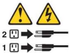
•Statement 10
CAUTION:
Donotplaceanyobjectweighingmorethan82kg(180lbs.)ontopof rack-mounteddevices.

Importante:
natural_image
Symbolic icon showing two human figures carrying a box inside a circle (no text or symbols)

≥18 kg ≥32 kg ≥55 kg
PRECAUCIÓN:
This information was developed for products and services offered in the U.S.A.
IBM may not offer the products, services, or features discussed in this document in other countries. Consult your local IBM representative for information on the products and services currently available in your area. Any reference to an IBM product, program, or service is not intended to state or imply that only that IBM product, program, or service may be used. Any functionally equivalent product, program, or service that does not infringe any IBM intellectual property right may be used instead. However, it is the user's responsibility to evaluate and verify the operation of any non-IBM product, program, or service.
IBM may have patents or pending patent applications covering subject matter described in this document. The furnishing of this document does not give you any license to these patents. You can send license inquiries, in writing, to:
IBMDirectorofLicensing
IBMCorporation
NorthCastleDrive
Armonk,NY10504-1785
U.S.A.
INTERNATIONAL BUSINESS MACHINES CORPORATION PROVIDES THIS PUBLICATION "AS IS" WITHOUT WARRANTY OF ANY KIND, EITHER EXPRESS OR IMPLIED, INCLUDING, BUT NOT LIMITED TO, THE IMPLIED WARRANTIES OF NON-INFRINGEMENT, MERCHANTABILITY OR FITNESS FOR A PARTICULAR PURPOSE. Some states do not allow disclaimer of express or implied warranties in certain transactions, therefore, this statement may not apply to you.
This information could include technical inaccuracies or typographical errors. Changes are periodically made to the information herein; these changes will be incorporated in new editions of the publication. IBM may make improvements and/or changes in the product(s) and/or the program(s) described in this publication at any time without notice.
Any references in this information to non-IBM Web sites are provided for convenience only and do not in any manner serve as an endorsement of those Web sites. The materials at those Web sites are not part of the materials for this IBM product, and use of those Web sites is at your own risk.
IBM may use or distribute any of the information you supply in any way it believes appropriate without incurring any obligation to you.
Trademarks
The following terms are trademarks of International Business Machines Corporation in the United States, other countries, or both:
Active Memory Predictive Failure Analysis
Active PCI PS/2
Active PCI-X ServeRAID
Alert on LAN ServerGuide
C2T Interconnect ServerProven
Chipkill TechConnect
EtherJet Tivoli
e-business logo Tivoli Enterprise
FlashCopy Update Connector
IBM Wake on LAN
IntelliStation XA-32
Light Path Diagnostics XA-64
NetBAY X-Architecture
Netfinity XceL4
NetView XpandOnDemand
OS/2 WARP xSeries
Lotus, Lotus Notes, SmartSuite, and Domino are trademarks of Lotus Development Corporation and/or IBM Corporation in the United States, other countries, or both.
ActionMedia, LANDesk, MMX, Pentium, and ProShare are trademarks of Intel Corporation in the United States, other countries, or both.
Microsoft, Windows, and Windows NT are trademarks of Microsoft Corporation in the United States, other countries, or both.
UNIX is a registered trademark of The Open Group in the United States and other countries.
Java and all Java-based trademarks and logos are trademarks or registered trademarks of Sun Microsystems, Inc. in the United States, other countries, or both.
Linux is a registered trademark of Linus Torvalds.
Other company, product, or service names may be trademarks or service marks of others.
Importantnotes
Processor speeds indicate the internal clock speed of the microprocessor; other factors also affect application performance.
CD-ROM drive speeds list the variable read rate. Actual speeds vary and are often less than the maximum possible.
When referring to processor storage, real and virtual storage, or channel volume, KB stands for approximately 1000 bytes, MB stands for approximately 1 000 000 bytes, and GB stands for approximately 1 000 000 000 bytes.
When referring to hard disk drive capacity or communications volume, MB stands for 1 000 000 bytes, and GB stands for 1 000 000 000 bytes. Total user-accessible capacity may vary depending on operating environments.
Maximum internal hard disk drive capacities assume the replacement of any standard hard disk drives and population of all hard disk drive bays with the largest currently supported drives available from IBM.
Maximum memory may require replacement of the standard memory with an optional memory module.
IBM makes no representation or warranties regarding non-IBM products and services that are ServerProven ® , including but not limited to the implied warranties of merchantability and fitness for a particular purpose. These products are offered and warranted solely by third parties.
IBM makes no representations or warranties with respect to non-IBM products. Support (if any) for the non-IBM products is provided by the third party, not IBM.
Some software may differ from its retail version (if available), and may not include user manuals or all program functionality.
Electronicemissionnotices
FederalCommunicationsCommission(FCC)statement
Note: This equipment has been tested and found to comply with the limits for a Class A digital device, pursuant to Part 15 of the FCC Rules. These limits are designed to provide reasonable protection against harmful interference when the equipment is operated in a commercial environment. This equipment generates, uses, and can radiate radio frequency energy and, if not installed and used in accordance with the instruction manual, may cause harmful interference to radio communications. Operation of this equipment in a residential area is likely to cause harmful interference, in which case the user will be required to correct the interference at his own expense.
Properly shielded and grounded cables and connectors must be used in order to meet FCC emission limits. Properly shielded and grounded cables and connectors must be used in order to meet FCC emission limits. IBM is not responsible for any radio or television interference caused by using other than recommended cables and connectors or by using other than recommended cables and connectors or by unauthorized changes or modifications to this equipment. Unauthorized changes or modifications could void the user's authority to operate the equipment.
This device complies with Part 15 of the FCC Rules. Operation is subject to the following two conditions: (1) this device may not cause harmful interference, and (2) this device must accept any interference received, including interference that may cause undesired operation.
IndustryCanadaClassAemissioncompliancestatement
This Class A digital apparatus complies with Canadian ICES-003.
Avisdeconformitéàlaréglementationd'IndustrieCanada
Attention: This is a Class A product. In a domestic environment this product may cause radio interference in which case the user may be required to take adequate measures.
UnitedKingdomtelecommunicationssafetyrequirement
NoticetoCustomers
This apparatus is approved under approval number NS/G/1234/J/100003 for indirect connection to public telecommunication systems in the United Kingdom.
EuropeanUnionEMCDirectiveconformancestatement
This product is in conformity with the protection requirements of EU Council Directive 89/336/EEC on the approximation of the laws of the Member States relating to electromagnetic compatibility. IBM cannot accept responsibility for any failure to satisfy the protection requirements resulting from a nonrecommended modification of the product, including the fitting of non-IBM option cards.
This product has been tested and found to comply with the limits for Class A Information Technology Equipment according to CISPR 22/European Standard EN 55022. The limits for Class A equipment were derived for commercial and industrial environments to provide reasonable protection against interference with licensed communication equipment.
Attention: This is a Class A product. In a domestic environment this product may cause radio interference in which case the user may be required to take adequate measures.
TaiwaneseClassAwarningstatement
JapaneseVoluntaryControlCouncilforInterference(VCCI)statement
- IBM
- Note
- Aboutthismanual
- Important safety information
- Contents
- Chapter 5. Removing and installing FRUs (service only) ..... 51
- Chapter 6. Symptom-to-FRU index . . . . . . . . . . . . . . . . . . . . . . . . . . . . . . 63
- Chapter1.Generalinformation
- Relatedpublications
- Noticesandstatementsinthisbook
- Featuresandspecifications
- ServerControls,LEDsandpower
- Frontview
- Rearview
- Serverpowerfeatures
- Turningontheserver
- DANGER
- Turningofftheserver
- CAUTION:
- Chapter2.Configuringyourserver
- - Configuration/SetupUtilityprogram
- • IBMServerGuideSetupandInstallationCD
- •SCSISelectUtilityprogram(somemodels)
- •GigabitEthernetcontrollerconfiguration
- •IBMDirector
- UsingtheConfiguration/SetupUtilityprogram
- StartingtheConfiguration/SetupUtilityprogram
- Passwords
- Power-onpassword
- Administratorpassword
- UsingtheServerGuideSetupandInstallationCD
- ServerGuidefeatures
- Setupandconfigurationoverview
- Notes:
- SystemPartition
- Typicaloperating-systeminstallation
- Settinguporupdatingmultipleservers
- InstallingyouoperatingsystemwithoutServerGuide
- UsingtheSCSISelectUtilityprogram
- StartingtheSCSISelectUtilityprogram
- SCSISelectUtilitymenuchoices
- -Configuration
- - SCSIControllerID
- - SCSIControllerParity
- - SCSIControllerTermination
- •AdditionalConfiguration
- - BootDeviceOptions
- - SCSlDeviceConfiguration
- •BIOSInformation
- - Interrupt(IRQ)Channel
- - I/OPortAddress
- •SCSIDiskUtilities
- ConfiguringtheGigabitEthernetcontroller
- High-performanceEthernetoptions
- Teamingoptions
- Chapter3.Diagnostics
- Generalcheckout
- Checkoutprocedure
- ISTHESYSTEMPARTOFACLUSTER?
- IFTHESYSTEMISNOTPARTOFACLUSTER:
- DIDYOURECEIVEBOTHOFTHECORRECTRESPONSES?
- Diagnostictoolsoverview
- •POSTbeepcodesanderrormessages
- - Errorlog
- •ServerGuideerrorsymptoms
- •Diagnosticprogramsanderrormessages
- - Errorsymptomcharts
- - Customizedsupportpage
- POST
- POSTbeepcodes
- Errorlogs
- ViewingerrorlogsfromtheConfiguration/SetupUtilityprogram
- Viewingerrorlogsfromdiagnosticprograms
- ServerGuideerrorsymptoms
- Smallcomputersysteminterfacemessages
- Diagnosticprogramsanderrormessages
- Textmessages
- FunctionName
- NotApplicable
- testspecificstring
- Startingthediagnosticprograms
- UsingthediagnosticsCD
- Downloadingthediagnosticsprogram
- Usingthediagnosticdiskette
- Viewingthetestlog
- ViewingtheSystemErrorlog
- Diagnosticerrormessagetables
- RecoveringtheBIOScode
- UpdatingtheUUID
- UpdatingtheDMI/SMBIOSdata
- Powercheckout
- TroubleshootingtheEthernetcontroller
- Networkconnectionproblems
- Ethernetcontrollertroubleshootingchart
- Ethernetcontroller messages
- Chapter4.Customerreplaceableunits
- Installationguidelines
- Systemreliabilityguidelines
- Handlingstatic-sensitivedevices
- MajorcomponentsofthexSeries305Type8673
- System-boardillustrations
- System-boardandriser-cardoptionconnectors
- System-boardinternalcableconnectors
- System-boardexternalportconnectors
- System-boardswitchesandjumpers
- System-boardLEDs
- Removingthecover
- Note:
- Workingwithadapters
- Adapterconsiderations
- Installinganadapter
- Harddiskdrives
- Installingorreplacingaharddiskdrive
- InstallingDIMMs
- Completingtheinstallation
- Installingthecover
- Updatingyourserverconfiguration
- Replacingthebattery
- Statement2:
- Disposeofthebatteryasrequiredbylocalordinancesorregulations.
- Input/outputportsandconnectors
- Serialport
- Viewingorchangingtheserial-portassignments
- Serial-portconnector
- UniversalSerialBusports
- USBcablesandhubs
- USB-portconnectors
- Keyboardconnector
- Videoconnector
- Auxiliary-device(pointingdevice)connector
- GigabitEthernetport
- High-performanceEthernetmodes
- Ethernetportconnector
- Cablingtheserver
- Chapter5.RemovingandinstallingFRUs(serviceonly)
- Thermalgrease
- Removingandreplacingamicroprocessor
- Removing andreplacingtheretentionmodule
- Removingandreplacingthesystemboard
- Important: When replacing the system board, you must:
- Removingandreplacingtheswitch/LED/USBcard
- Removingandreplacingapowersupply
- RemovingandreplacingthePCIrisercard
- Removingandreplacingthefans
- Removingandreplacingtheblower
- Removingandreplacingtheairbaffle
- Chapter6.Symptom-to-FRUindex
- Beepsymptoms
- Diagnosticerrorcodes
- POSTerrorcodes
- POST(ISPR)errorprocedures
- EF10(Default ISPR)
- DonotpressF5.Doingsochangestheserver'sconfiguration.
- If ISPR error is EF10 after disconnecting cables:
- FFFForothercodenotlisted
- ServeRAIDerrorcodes
- Undeterminedproblems
- Chapter7.PartslistingxSeries305Type8673
- Server
- KeyboardCRUs
- KeyboardCRUNo.
- Powercords
- AppendixA.Gettinghelpandtechnicalassistance
- Beforeyoucall
- Usingthedocumentation
- GettinghelpandinformationfromtheWorldWideWeb
- Softwareserviceandsupport
- Hardwareserviceandsupport
- AppendixB.Relatedserviceinformation
- Safetyinformation
- Generalsafety
- Electricalsafety
- Safetyinspectionguide
- Checklist:
- Handlingelectrostaticdischarge-sensitivedevices
- Groundingrequirements
- Safetynotices(multilingualtranslations)
- Toavoidashockhazard:
- Donot:
- Importante:
- PRECAUCIÓN:
- Trademarks
- Importantnotes
- Electronicemissionnotices
- FederalCommunicationsCommission(FCC)statement
- IndustryCanadaClassAemissioncompliancestatement
- Avisdeconformitéàlaréglementationd'IndustrieCanada
- UnitedKingdomtelecommunicationssafetyrequirement
- NoticetoCustomers
- EuropeanUnionEMCDirectiveconformancestatement
- TaiwaneseClassAwarningstatement
- JapaneseVoluntaryControlCouncilforInterference(VCCI)statement
Brand : IBM
Model : eServer xSeries 305
Category : Server