BLADE H 15 EVO - Poêle à granulés EDILKAMIN - Notice d'utilisation et mode d'emploi gratuit
Retrouvez gratuitement la notice de l'appareil BLADE H 15 EVO EDILKAMIN au format PDF.

| Type de produit | Poêle à granulés à eau (bouilleur) |
| Marque | Edilkamin |
| Modèle | BLADE H 15 EVO |
| Dimensions (acier) | Larg. 76 cm, Prof. 37 cm, Haut. 110 cm |
| Poids (selon habillage) | 230 / 250 / 280 kg |
| Alimentation électrique | 230 Vac +/-10% 50 Hz |
| Puissance électrique absorbée nominale | 42 W |
| Puissance thermique nominale | 14,9 kW |
| Puissance thermique réduite | 5 kW |
| Rendement nominal / réduit | 90% / 93,9% |
| Capacité du réservoir de granulés | 23 kg |
| Autonomie (nominale / réduite) | 7 h / 21 h |
| Classe énergétique | A+ |
| Teneur en eau du circuit | 13 l |
| Pression maximale de fonctionnement | 3 bar |
| Diamètre sortie fumées | 80 mm |
| Diamètre entrée air comburant | 50 mm |
| Types d'habillage disponibles | Acier, Céramique, Verre |
| Fonctions de régulation | Manuel, Automatique, Programmation hebdomadaire (Crono) |
| Interface utilisateur | Écran tactile + application The Mind, compatible Alexa/Google Home (options) |
| Entretien courant | Nettoyage quotidien du creuset et du tiroir à cendres |
| Maintenance saisonnière | Par un technicien agréé : ramonage conduit, nettoyage intérieur |
| Sécurité | Arrêt automatique en cas de panne, ventilateur de sécurité, pressostat |
| Pièces détachées | Disponibles auprès du réseau agréé Edilkamin |
FOIRE AUX QUESTIONS - BLADE H 15 EVO EDILKAMIN
Questions des utilisateurs sur BLADE H 15 EVO EDILKAMIN
0 question sur cet appareil. Repondez a celles que vous connaissez ou posez la votre.
Poser une nouvelle question sur cet appareil
Téléchargez la notice de votre Poêle à granulés au format PDF gratuitement ! Retrouvez votre notice BLADE H 15 EVO - EDILKAMIN et reprennez votre appareil électronique en main. Sur cette page sont publiés tous les documents nécessaires à l'utilisation de votre appareil BLADE H 15 EVO de la marque EDILKAMIN.
MODE D'EMPLOI BLADE H 15 EVO EDILKAMIN
PELLET BOILER STOVE
BLADE H 15 EVO
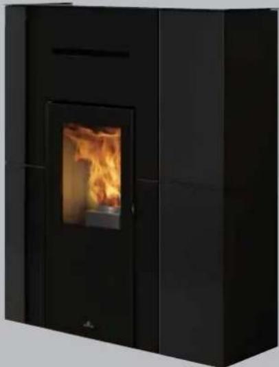
natural_image
Black industrial stove burner with visible flame inside, no text or symbols presentUpgrade www.edilkamin.com
GB Installation, use and maintenance
The original language of this manual is Italian
The undersigned EDILKAMIN S.p.A., with registered office in Via P. Moscati 8 - 20154 Milan (Italy) - Tax ID Code and VAT number 00192220192
Hereby declares, under its sole responsibility, that: the pellet boiler stoves mentioned below are conforming with EU Regulation 305/2011 and harmonised EU standard EN 16510-1:2022
EN 16510-2-6:2022
PELLET BOILER STOVE, bearing the
EDILKAMIN trademark, named
BLADE H 15 EVO
SERIAL NO.: Rating plate reference
BLADE H 15 EVO Declaration of performance (DoP - EK no. 328)
Moreover, the company hereby declares that: the above-mentioned wood-burning pellet stoves satisfy the requirements of the following European directives:
2014/35/EU - Low Voltage Directive
2014/30/EU - Electromagnetic Compatibility Directive
2011/65/EU - RoHS
2009/125/EU - Ecodesign
2010/30/EU - Labelling
Dear Sir/Madam
The product is uniquely identified by a number,
its
We thank you for and congratulate you on choosing "counterfoil".
product. Before using it, we ask you to read this manual
carefully, in order for you to be able to make the most of all its functions in total safety.
This manual is an integral part of the product. We ask you to keep it for the entire lifetime of the product. If you lose it, you can request a copy from your dealer or down load it from www.edilkamin.com
Readers of this manual
This manual is addressed to:
- those who will use the product at home ("USER");
- the technician who will install the product ("INSTALLER")
The target person of each page is indicated in a band at the bottom of the page (USER or INSTALLER).
General information
After unpacking the product, check the condition and completeness of the contents.
In the event of error, immediately contact the retailer where the purchase was made, providing them with a copy of the warranty booklet and the sales receipt.
All local, national laws and European Standards must met in the proper sizing, installation, maintenance and use of the appliance. Refer to local codes in each cou installation and for anything not specifically mentioned.
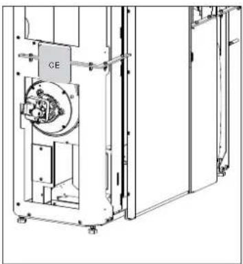
The diagrams provided in this manual are for illustration. The CE plate of the product purposes only: they do not always strictly refer to your specific model, and are not binding in any way.
Which can be found on:
- the packaging;
• the CE marking plate;
• the warranty certificate accompanying the product.
The warranty conditions are given in the warranty certificate accompanying the product and on the website www.edilkamin.com.
text_image
EDIL KAMIN CERTIFICATO: DI GARANZIA 1. 2017 2. 2018 3. 2019 4. 2020 5. 2021 6. 2022 7. 2023 8. 2024 9. 2025 10. 2026 11. 2027 12. 2028 13. 2029 14. 2030 15. 2031 16. 2032 17. 2033 18. 2034 19. 2035 20. 2036 21. 2037 22. 2038 23. 2039 24. 2040 25. 2041 26. 2042 27. 2043 28. 2044 29. 2045 30. 2046 31. 2047 32. 2048 33. 2049 34. 2050 35. 2051 36. 2052 37. 2053 38. 2054 39. 2055 40. 2056 41. 2057 42. 2058 43. 2059 44. 2060 45. 2061 46. 2062 47. 2063 48. 2064 49. 2065 50. 2066 51. 2067 52. 2068 53. 2069 54. 2070 55. 2071 56. 2072 57. 2073 58. 2074 59. 2075 60. 2076 61. 2077 62. 2078 63. 2079 64. 2080 65. 2081 66. 2082 67. 2083 68. 2084 69. 2085 70. 2086 71. 2087 72. 2088 73. 2089 74. 2090 75. 2091 76. 2092 77. 2093 78. 2094 79. 2095 80. 2096 81. 2097 82. 2098 83. 2099 84. 2100This document may be subject to changes dictated by the Manufacturer or by the regulations in force at the time of purchase.
The updated version that is currently in force will always be available from the download area of the website
try for edilkamin.com
MEANING OF SYMBOLS
In some parts of the manual the following symbols are used:
PLEASE NOTE:
carefully read and understand the message in question, since failure follows the instructions in it could cause serious damage to the product and put the safety of those using it at risk.

INFORMATION:
failure to comply with these requirements will compromise product use.

OPERATING SEQUENCE:
follow the instructions for the operations described
to
natural_image
Technical line drawing of a mechanical device with labeled component 'CE' (no readable text or symbols beyond label)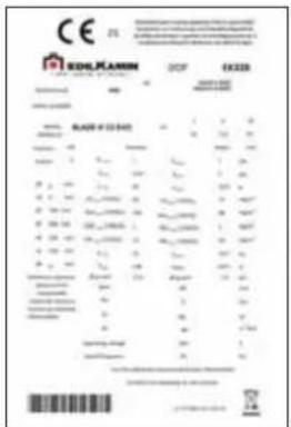
text_image
Technical specification sheet from Einkam, 2019, showing material grades, dimensions, and specifications for a cast iron.This appliance can be used by children aged from 8 years and above and persons with reduced physical, sensory or mental capabilities or lack of experience and knowledge if they have been given supervision or instruction concerning use of the appliance in a safe way and understand the hazards involved.
• Children shall not be allowed to tamper with the controls or play with the appliance.
- Cleaning and user maintenance shall not be made by children without supervision.
Symbols on data plate
• Pw nom = Rated water power
• Pw part = Reduced water power
- nom= Rated yield
• η part = Reduced yield
• CO nom (13%O2)= Rated CO
• CO part (13%O2) = Reduced CO
- Nox nom (13%O2) = Rated NOX
- Nox part (13%O2) = Reduced NOX
• OGC nom (13%O2) = Rated OGC
• OGC part (13%O2) = Reduced OGC
• PM nom (13%O2) = Rated dust emissions
• PM part (13%O2) = Reduced dust emissions
• p nom = Rated power
• p part = Reduced power
• T nom = Rated smoke temperature
• T part = Reduced smoke temperature
• φf,g nom = Rated mass flow rate
• φf,g part = Reduced mass flow rate
• dout = Fume outlet diameter
• Pw = Maximum pressure
• W = Rated electrical power according to EN 60335
• dR = Rear safety distance
• dS = Side safety distance
• dC = Upper safety distance
• dP = Front safety distance
• dF = Radiated floor safety distance
• dL = Radiated side safety distance
• dB = Floor safety distance
• Vh = Firebox classification according to pr EN 16510/Load loss
- The product is not designed for use people, including children, with limited physical, sensory and mental abilities.
- The appliance is not designed for cooking purposes.
- The appliance is designed to burn UNI EN ISO 17225-2 category A1 wood pellets, in the amounts and manner described in this manual.
- The appliance is designed for indoor use and in areas with normal humidity conditions.
- Keep the product in a dry place out of the weather.
- For the legal and company warranties, refer to the warranty certificate inside the product: specifically, neither Edilkamin nor the retailer are liable for damage resulting from incorrect installation or maintenance.
Safety risks may be caused by:
- installation in non-suitable settings, in particular those that are subject to fire risks. DO NOT INSTALL THE PRODUCT IN AREAS SUBJECT TO THE RISK OF FIRE.
- contact with fire and hot parts (e.g. glass panel and pipes). DO NOT TOUCH HOT PARTS and, when the stove is switched off and still hot, always wear the glove.
- contact with live electrical equipment (internal). DO NOT ACCESS THE INTERNAL ELECTRICAL EQUIPMENT WHILE THE APPLIANCE IS POWERED ON. Electrocution hazard.
- Use of improper ignition aids (e.g. alcohol). DO NOT IGNITE OR BOOST THE FLAME WITH FLUID SPRAYS OR A FLAME TORCH. Serious risk of burns, damage and injury.
- Use of fuel other than wood pellets. NOT BURN WASTE TMR, PLASTIC OR MATERIALS OTHER THAN WOOD PELLETS IN THE COMBUSTION CHAMBER. The product may become soiled, the flue may catch fire, and environmental damage may ensue.
- Cleaning the combustion chamber when hot. DO NOT CLEAN THE COMBUSTION CHAMBER WITH A VACUUM CLEANER WHILE IT IS HOT. You could damage the vacuum-cleaner and risk the emission of smoke in the room.
• cleaning the glass pane while hot or with unsuitable cleaning products. DO
- Cleaning the smoke duct with cleaning √ For reasons of safety, read the user products. DO NOT CLEAN THE PRODUCT WITH FLAMMABLE PRODUCTS. Risk of fire or blowback.
by NOT CLEAN HOT GLASS WITH WATER. ONLY USE RECOMMENDED GLASS CLEANING PRODUCTS. Risk of cracking and permanent, irreparable damage to the glass.
- The storage of flammable materials at a distance which is less than the safe distances listed in this manual. DO NOT PLACE LAUNDRY ON THE APPLIANCE. DO NOT PLACE DRYING RACKS WITHIN THE SAFETY CLEARANCE. Keep flammable fluids away from the appliance. Fire hazard.
- Blocking the aeration vents and air intakes in the room. DO NOT BLOCK THE AERATION VENTS OR FLUE. Risk of smoke returning into the room with consequent damage and injury.
- Use of the product as a support or ladder. DO NOT CLIMB ONTO THE PRODUCT OR USE IT AS A SUPPORT. Risk of damage and injury.
Use of the stove with the combustion chamber door open. DO NOT USE THE PRODUCT WITH ITS DOOR OPEN. - Incandescent material projected from the open door. DO NOT throw incandescent material outside the appliance. Fire ed hazard.
- Use of water in case of fire. CALL THE AUTHORITIES if a fire breaks out.
Licensed and qualified Technical Assistance Centre/Edilkamin retailers company names are available on the Edilkamin website www.edilkamin.com ONLY.
√ Never operate the product without water in DQthe circuit. Running it dry can damage it.
√ If you have doubts, please do not take any action, but contact the dealer or the installer.
√ Switch the appliance on ONLY with the cladding mounted.
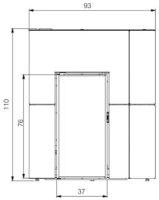
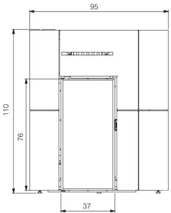
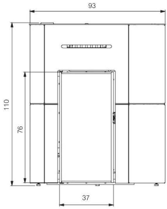
BLADE H 15 EVO (cm) - STEEL
text_image
93 110 76 37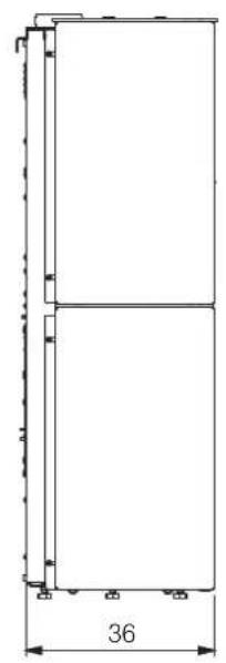
natural_image
Pure architectural or mechanical diagram showing two vertical panels with a dimension label '36' at the bottom (no text or symbols within the diagram itself)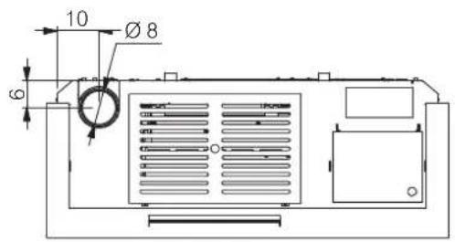
text_image
10 Ø 8 6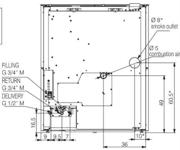
text_image
FILLING G 3/4" M RETURN G 3/4" M DELIVERY G 1/2" M 16,5 9 9,5 7 Ø 8* smoke outlet Ø 5 combustion air 49 60,5* 10* 36*for rear exit smoke, with optional
BLADE H 15 EVO (cm) - CERAMIC
text_image
95 110 76 37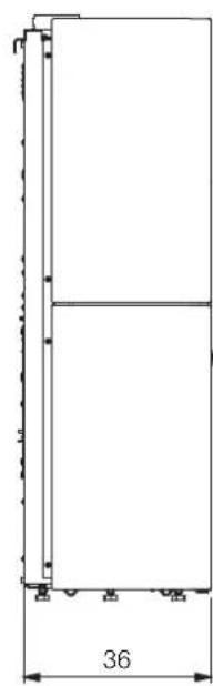
natural_image
Pure technical line drawing of a vertical rectangular structure with dimension标注 (no text or symbols)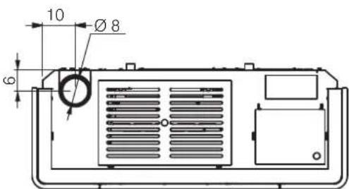
text_image
10 Ø 8 6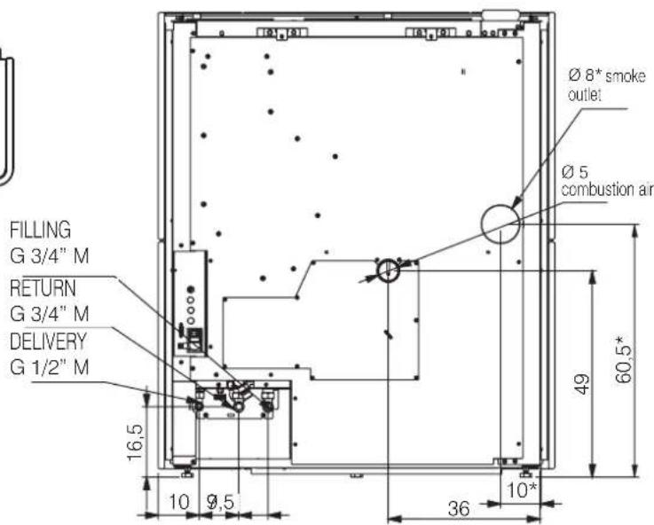
text_image
FILLING G 3/4" M RETURN G 3/4" M DELIVERY G 1/2" M 16,5 10 9,5 Ø 8* smoke outlet Ø 5 combustion air 49 60,5* 36 10**for rear exit smoke, with optional
BLADE H 15 EVO (cm) · GLASS
text_image
93 110 76 37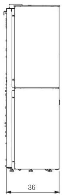
natural_image
Pure architectural or mechanical diagram showing a vertical frame with dimension标注 (no text or symbols)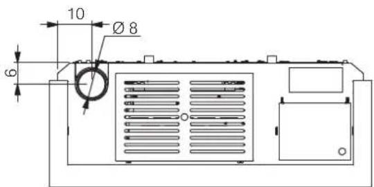
text_image
10 Ø 8 6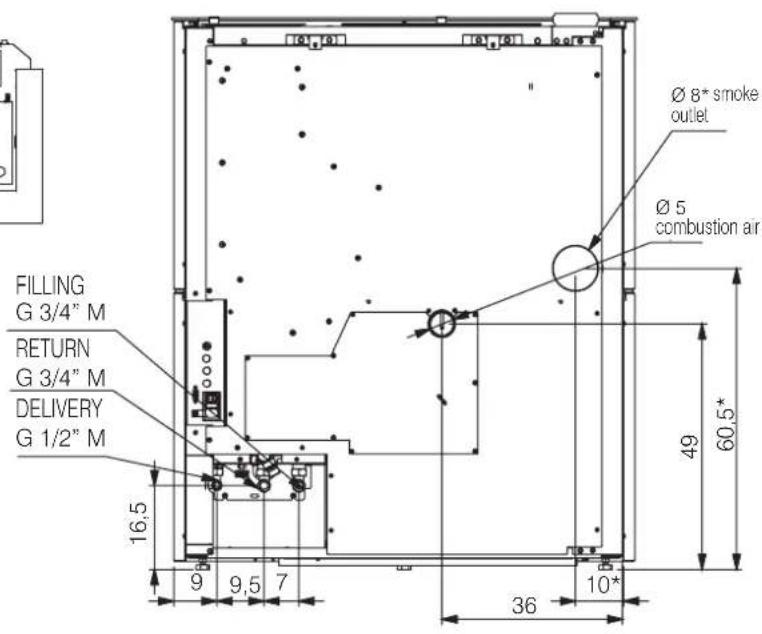
text_image
FILLING G 3/4" M RETURN G 3/4" M DELIVERY G 1/2" M 16,5 9 9,5 7 Ø 8* smoke outlet Ø 5 combustion air 49 60,5* 36 10**for rear exit smoke, with optional
| TECHNICAL DATA pursuant to EN 16510 The data shown is purely indicative and was measured during the certification phase at notified bodies under standard conditions. | |||
| BLADE H 15 EVO | |||
| Nominal power Reduced power | |||
| Available power | 14,9 5 kW | ||
| Yield | 90 93,9 % | ||
| CO emissions at 13% O_2 | 0,005 0,006 % | ||
| Smoke temperature | 148 64,9 °C | ||
| Fuel consumption * | 3,4 1,1 | kg/h | |
| Tank capacity 23 kg | |||
| Recommended draught 12 Pa | |||
| Autonomy | 7 | 21 | ore |
| Water content | 13 | l | |
| Maximum operating pressure | 3 | bar | |
| Maximum operating temperature | 90 °C | ||
| Heatable volume ** | 390 | m^3 | |
| Smoke duct diameter | 80 | mm | |
| Air intake duct diameter | 50 | mm | |
| Weight including packaging | 230/250/280 | kg | |
| Energy efficiency class (Regulation 1185/ 2015) | A+ | ||
| Environmental Class according to the Italian Ministerial Decree 186 | 5 stars | ||
* A calorific value of 4.8 kW/kg was used to calculate consumption.
** The heatable volume was calculated with a heating demand of 33 Kcal/m³ hour.
The product can work safely even with greater draught.
Excessive draught could cause the product to switch off and/or lower its performance.
The flue outlet is not that of the chimney system, which must be sized in accordance with national and local standards and in particular, but not limited to, EN 13384, EN 1443, EN 1856, EN 1457.
| TECHNICAL DATA FOR SIZING THE FLUEwhich must in any case satisfy the requirements in this sheet and the installation instructions for the product | ||
| Nominal power | ||
| BLADE H 15 EVO | ||
| Smoke temperature at smoke outlet | 179 | °C |
| Minimum draught | 0,01 | Pa |
| Smoke flow rate | 13,4 | g/s |
| ELECTRICAL SPECIFICATIONS | |
| Power supply | 230 Vac +/- 10% 50 Hz |
| Nominal absorbed power | 42 W |
| Reduced absorbed power | 23 W |
| Absorbed power in stand-by mode | 4 W |
| Power absorption during ignition | 377 W |
| Protection rating | Fusibile 4 AT, 250 Vac 5x20 |
EDILKAMIN S.p.A. reserves the right to modify the product at its own discretion and without prior notice, with a view to improvements.

EDILKAMIN
TECNOLOGIA DEL FUOCO
Mattham-2 p A
2022C Monale (M), vs P. Matnagni T
Tel +08 02 937621
Fax: 739 02 93762 400300
www.essence.com
Copyright: \$100,000 net worth
Ede legale
20123 Milano, via Virgango Dandi 47
Reg. Rep. di Milano 02192220192
Cod. Focaiw e Partida NA 00192220192
TECHNICAL DOCUMENTATION FOR LOCAL SPACE HEATERS ACCORDING TO COMMISSION REGULATION (EU) 2015/1185 AND 2015/1186
| Manufacturer | Edilkamin S.p.A. | |
| Trademark | Edilkamin | |
| Model Identifier | BLADE H15 EVO | |
| Equivalent models | Trademak Edilkamin | |
| Trademak Innofire | ||
| Trademak Italiana Camini | ||
| Description | Mechanically space heater fired by wood pellets | |
| Indirect heating functionality | ||
| Direct heat output (space heat output) | 14,9 kW | |
| CPR harmonised standard | EN 16510-1:2022 - EN 16510-2-6:2022 | |
| Notified Body | Acteco srl (Via Amman 41,33084 Cordenons-PN-Italy) N81880 | |
| Fuel | Preferred fuel (only one) | Other suitable fuel(s) | Space heating emissions at nominal heat output(*) | Space heating emissions at minimum heat output(**) | ||||||
| PM | OGC | CO | NOx | PM | OGC | CO | NOx | |||
| mg/m3 at 13%O2 | mg/m3 at 13%O2 | |||||||||
| Wood log, moisture content ≤ 25 % | no | no | ||||||||
| Compressed wood with moisture content < 12 % | yes | no | 15 | 1 | 69 | 100 | 10 | 1 | 74 | 88 |
| Other woody biomass | no | no | ||||||||
| Non-woody biomass | no | no | ||||||||
| Anthracite and dry steam coal | no | no | ||||||||
| Hard coke | no | no | ||||||||
| Low temperature coke | no | no | ||||||||
| Bituminous coal | no | no | ||||||||
| Lignite briquettes | no | no | ||||||||
| Heat briquettes | no | no | ||||||||
| Blended fossil fuel briquettes | no | no | ||||||||
| Other fossil fuel | no | no | ||||||||
| Blended biomass and fossil fuel briquettes | no | no | ||||||||
| Other blend of biomass and solid fuel | no | no | ||||||||
(*) PM = particulate matter, OGCs = organic gaseous compounds, CO = carbon monoxide, NOx = nitrogen oxides (**). Only required if correction factors F(2) or F(3) are applied.
Observe the specific precautions for installation, assembly and maintenance indicated in the manual accompanying the product
| From 1/1/2022 | |
| _t [%] | 87,4 |
| EEI [%] | 128 |
| Energy Efficiency Class | A+ |
Calculations according to the council commission regulation (EU) 2015/1186 and 2015/1185 Characteristics when operating with the preferred fuel
| EEI = (_2,an · DLF) - 10% + I(2) + I(3) - I(4) - I(5) | BLF=1.45 | _2,an = _bn,n,w |
| _S = _2,an - 10% + I'(2) + I'(3) - I'(4) - I'(5) |

EDILKAMIN
TECNOLOGIA DEL FUOCO
Batharica
2015 LinkedIn (M) on F Management
36.4内部控制
(5)业绩快报或办理
Hongkowloon.com http://adillagomics.com
Copyright © 6.158.009 euro euros
Brook to Guatemala
2013 https://www.essence.com/
Fax: 01-585001017023742
表决:产生网络投票
Ciel, Paradow & Parisa: 1963-08-2023 股权
Characteristics when operating with the preferred fuel
| Heat output | |||
| Item | Symbol | Value | Unit |
| Nominal heat output | P_max | 14,9 | kW |
| Minimum heat output(indicative) | P_max | 5,0 | kW |
| Auxiliary electricity consumption | |||
| Item | Symbol | Value | Unit |
| At nominal heat output | eI_max | 0,042 | kW |
| At minimum heat output | eI_min | 0,023 | kW |
| In standby mode | eI_ab | 0,004 | kW |
$$ F (4) = C C \cdot \frac {0 . 2 \cdot e I _ {\max} + 0 . 8 \cdot e I _ {\max} + 1 . 3 \cdot e I _ {b}}{P _ {\max}} \cdot 1 0 0 [ \% ] $$
(18)
0.5%
CC+2.5
| Permanent pilot flame power requirement | |||
| Item | Symbol | Value | Unit |
| Pilot flame power requirement (if | P_ref | N.A. | kW |
F(S)
0.0%
$$ F [ 5 ] = 0. 5 \cdot \frac {P _ {\text {pdef}}}{P _ {\text {corr}}} \cdot 1 0 0 [ \% ] $$
| Useful efficiency (NCV as received) | |||
| Item | Symbol | Value | Unit |
| Useful efficiency at nominal heat output | _th,ave | 90 | % |
| Useful efficiency at minimum heat output (indicative) | _th,ave | 93.9 | % |
| Type of heat output/room temperature control (select one) | |
| single stage heat output, no room temperature control | NO |
| two or more manual stages, no room temperature control | NO |
| with mechanic thermostat room temperature control | NO |
| with electronic room temperature control | YES |
| with electronic room temperature control plus day timer | NO |
| with electronic room temperature control plus week timer | YES |
| F (Z) | 7,0 % | from 2022 |
| Other control options (multiple selections possible) | ||
| room temperature control, with presence detection | NO | |
| room temperature control, with open window | NO | |
| with distance control option | YES | |
F(3)
1.0%
from 2022
Contact details
Name and address of the manufacturer
EDILKAMIN S.p.A.
Via Mascagni 7
20045 Lainate (MI) - ITALY
Issue date: 03.06.2025
Tel. +39 02 937621
www.edikamin.com
mai@edikamrin.com

text_image
Don Gioggio FertelPREPARATION AND UNPACKING
The packaging materials are neither toxic nor noxious and do not require special disposal.
The user is responsible for storing, disposing of and recycling them in a regulatory fashion.

Always move the stove vertically with suitable equipment and in compliance with safety regulations.
Do not turn the package over, and handle all parts requiring installation with care.
TO REMOVE THE PALLET
Undo the for screws on each bracket
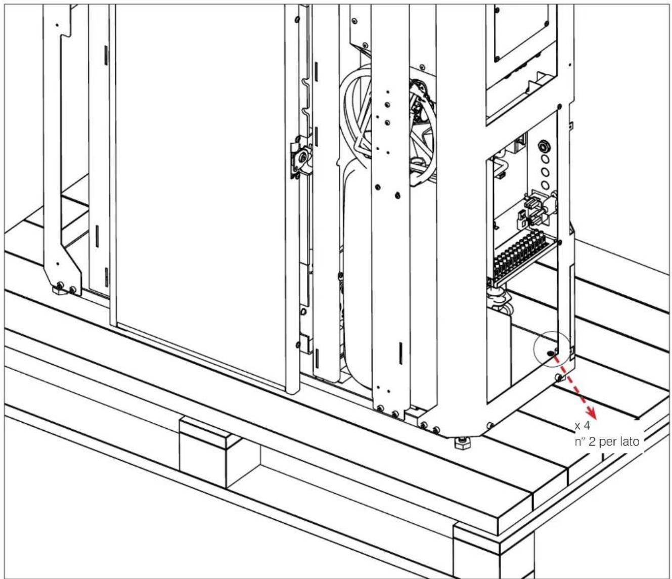
text_image
x 4 n° 2 per latoTHE DRAWINGS ARE FOR GUIDANCE ONLY, BUT THEY MAY NOT REFER TO THE SPECIFIC MODEL.
A REAR SMOKE DISCHARGE KIT exists as optional.
ADJUSTABLE FEET
The Blade H 15 EVO boiler stoves have adjustable feet to adapt to uneven floors.
The feet can be adjusted by slightly raising the boiler stove or using a screwdriver from above the foot.
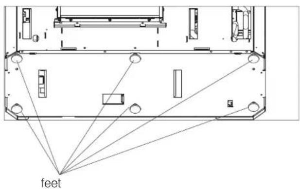
text_image
feetWALL MOUNTING
Mount the stove to the wall with the plates provided (a) and the brackets (b) already mounted on the product, or use alternative systems that guarantee that the product remains stable.
Fix the brackets to the wall using wall plugs.
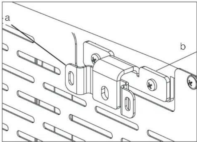
natural_image
Technical line drawing of a mechanical bracket assembly with labeled parts (a and b), no readable text or symbols present.THE DRAWINGS ARE FOR GUIDANCE ONLY, BUT THEY MAY NOT REFER TO THE SPECIFIC MODEL.
standard
natural_image
Technical line drawing of a mechanical assembly with mounting holes and control panel (no text or symbols)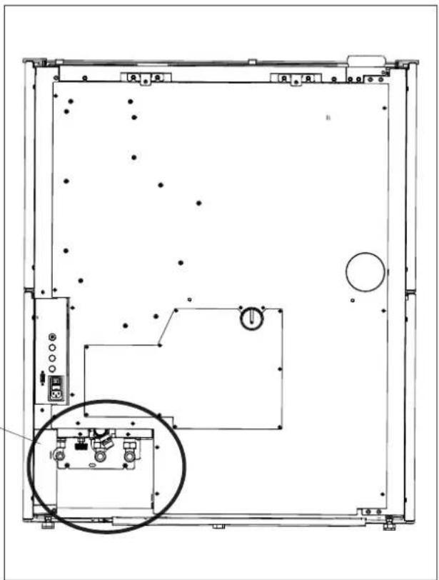
natural_image
Technical line drawing of a mechanical or electrical enclosure with internal components and no visible text or symbols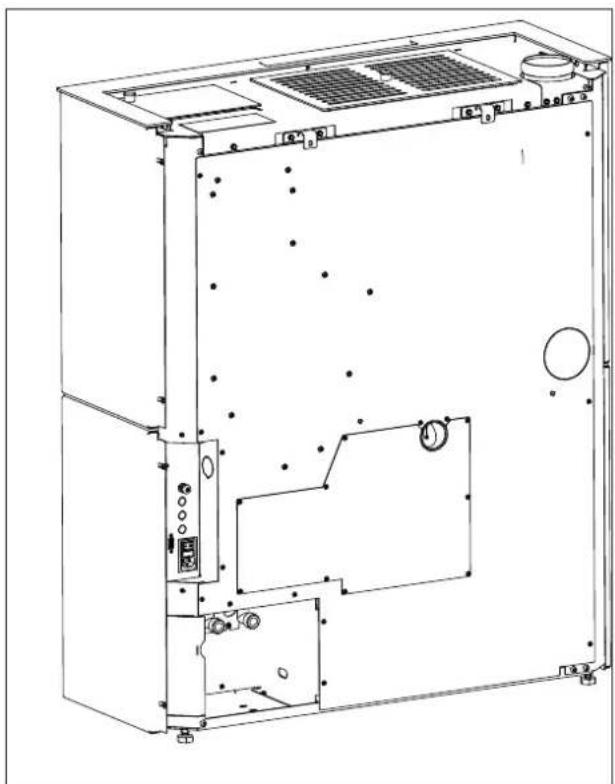
natural_image
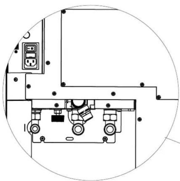
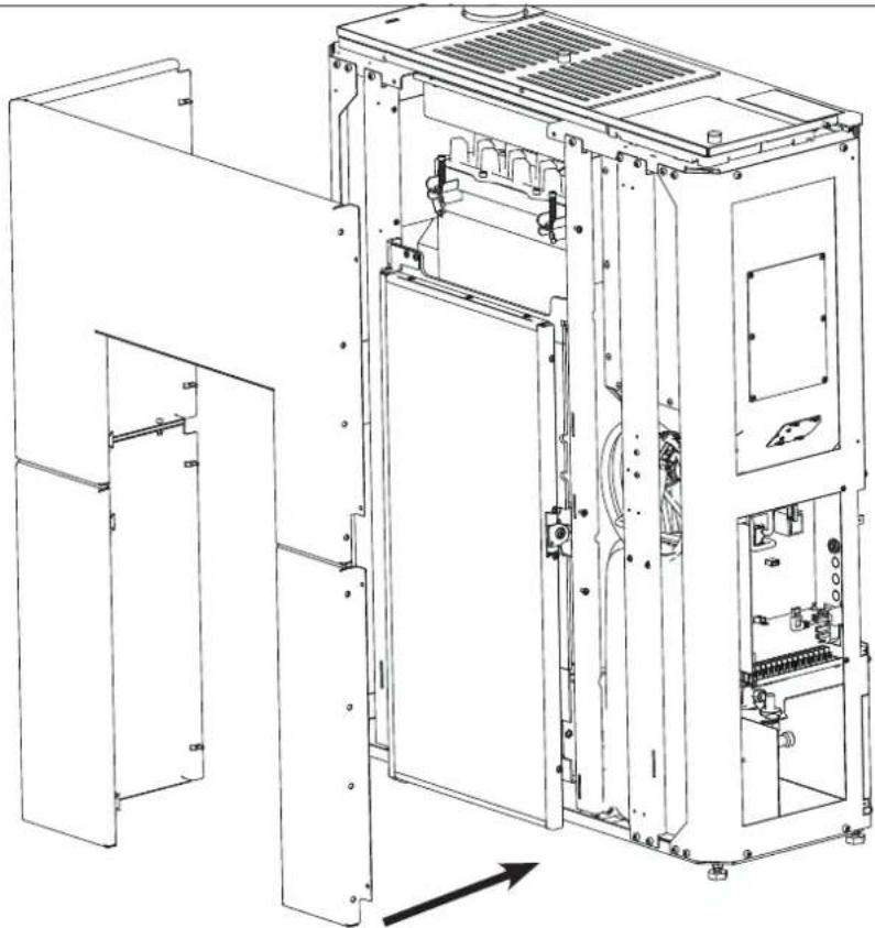
Technical line drawing of an open industrial machine casing with internal components and mounting holes (no text or labels)RIGHT-HAND SIDE HYDRAULIC FITTINGS
To have the hydraulic fittings on the right-hand side, it is possible to use commercial elbows and "exploit" the "recess" ("indent") between the pipes' outlet and the rear of the stove, as shown in the figure below. Remove B
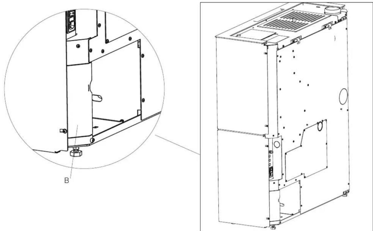
natural_image
Technical line drawing of a mechanical device showing internal components and a close-up view (no text or symbols)
When installing the kit, remove the rear and verify that the swivel nuts on the boiler stove's outlet pipes are closed.
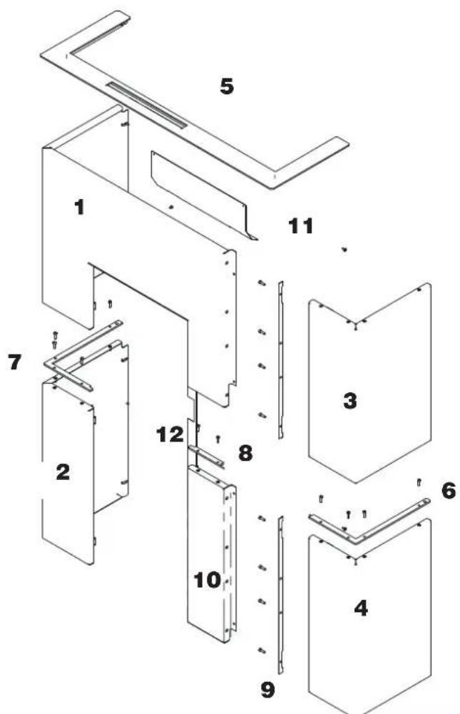
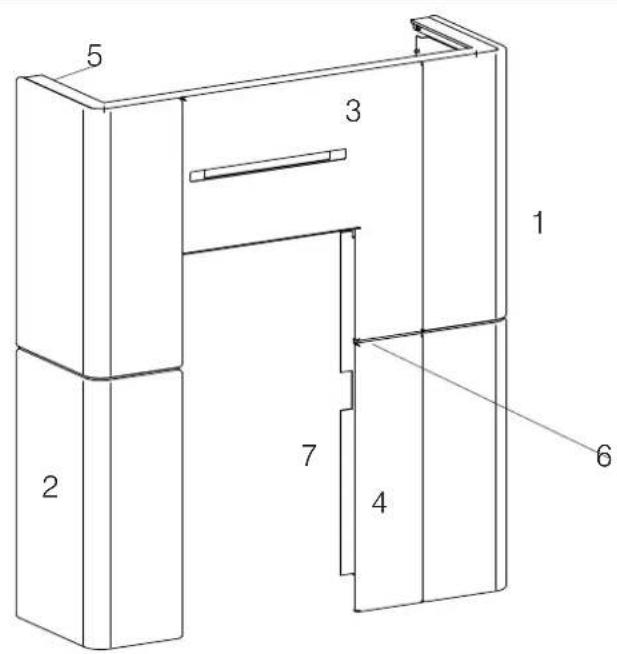
| Description Reference in the figures below Quantity | |
| Top left-hand side panel (1) n°1 | |
| Left-hand side panel (2) n°1 | |
| Top right-hand side panel (3) n°1 | |
| Right-hand side panel (4) n°1 | |
| Aesthetic top edge (5) n°1 | |
| Right profile (6) n°1 | |
| Left external profile (7) n°1 | |
| Left front profile (8) n°1 | |
| Central spacer (9) n°2 | |
| Bottom panel (10) n°1 | |
| Deflector (11) n°1 | |
| Filler profile | (11) n°1 |
| Small metal parts |
"Right" and "left" refer to the product when viewed from the front.
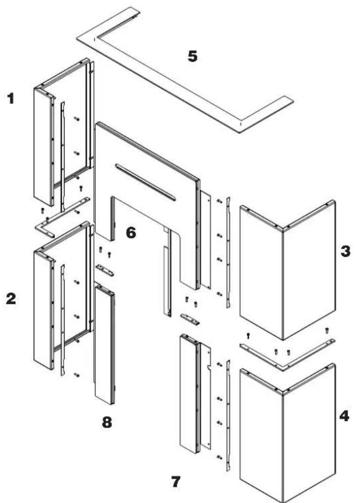
The above-mentioned elements, once they have been mounted, will be positioned ("exploded") as shown in the figure below. The mounting operations are described in the figures appearing on the following pages.
text_image
Exploded view diagram of a modular device with numbered components for identification
Levelling feet
The product is equipped with feet that can be adjusted with a screwdriver from inside the product BEFORE mounting the claddings, or by slightly raising the product.
BEFORE INSTALLING THE CLADDING, SECURE THE PRODUCT TO THE WALL WITH THE BRACKETS PROVIDED TO MAKE SURE IT DOES NOT TIP OVER.
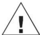
Before mounting the claddingput the deflector.
natural_image
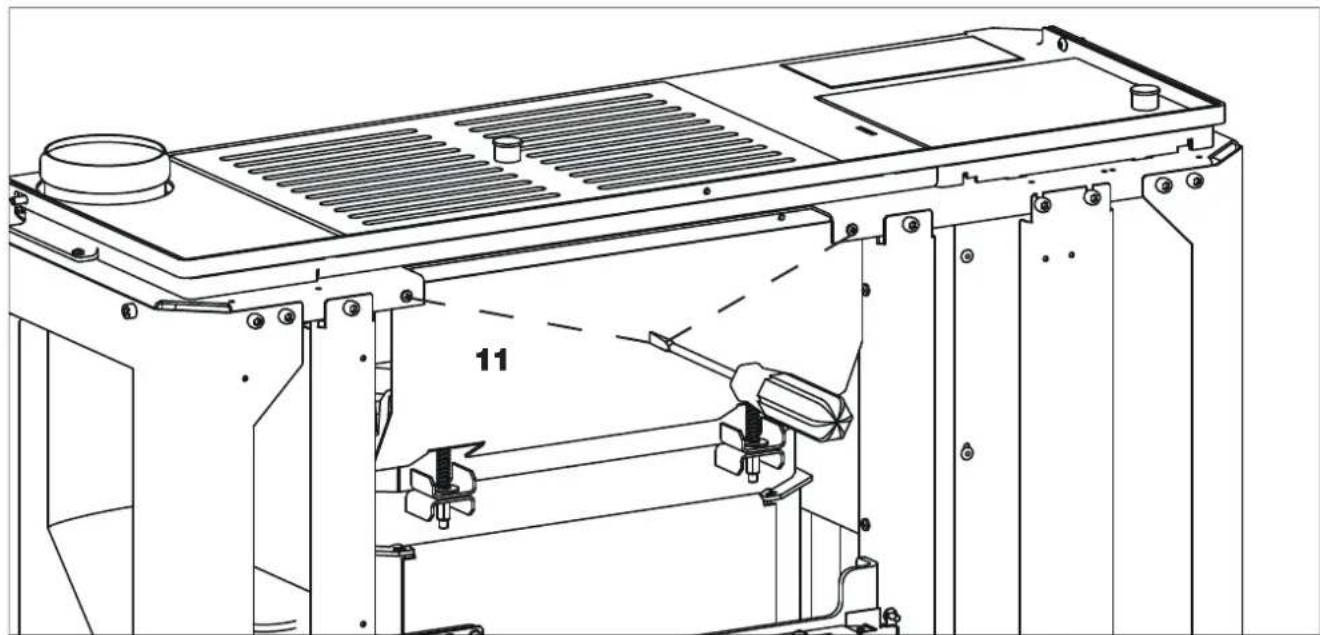
Technical line drawing of a mechanical assembly with labeled component '11' (no text or symbols beyond label)- Bend the upper flaps (A) to 90^ .
- Leave the lower fins (B) straight.
text_image
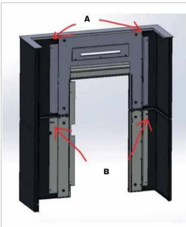
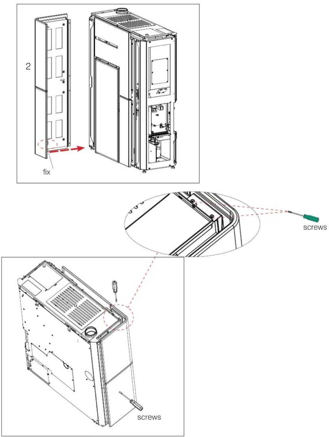
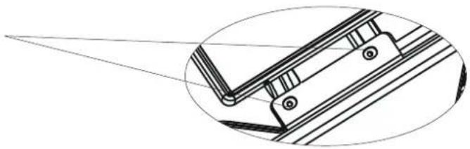
A BFitting of the assembled left-hand side panel
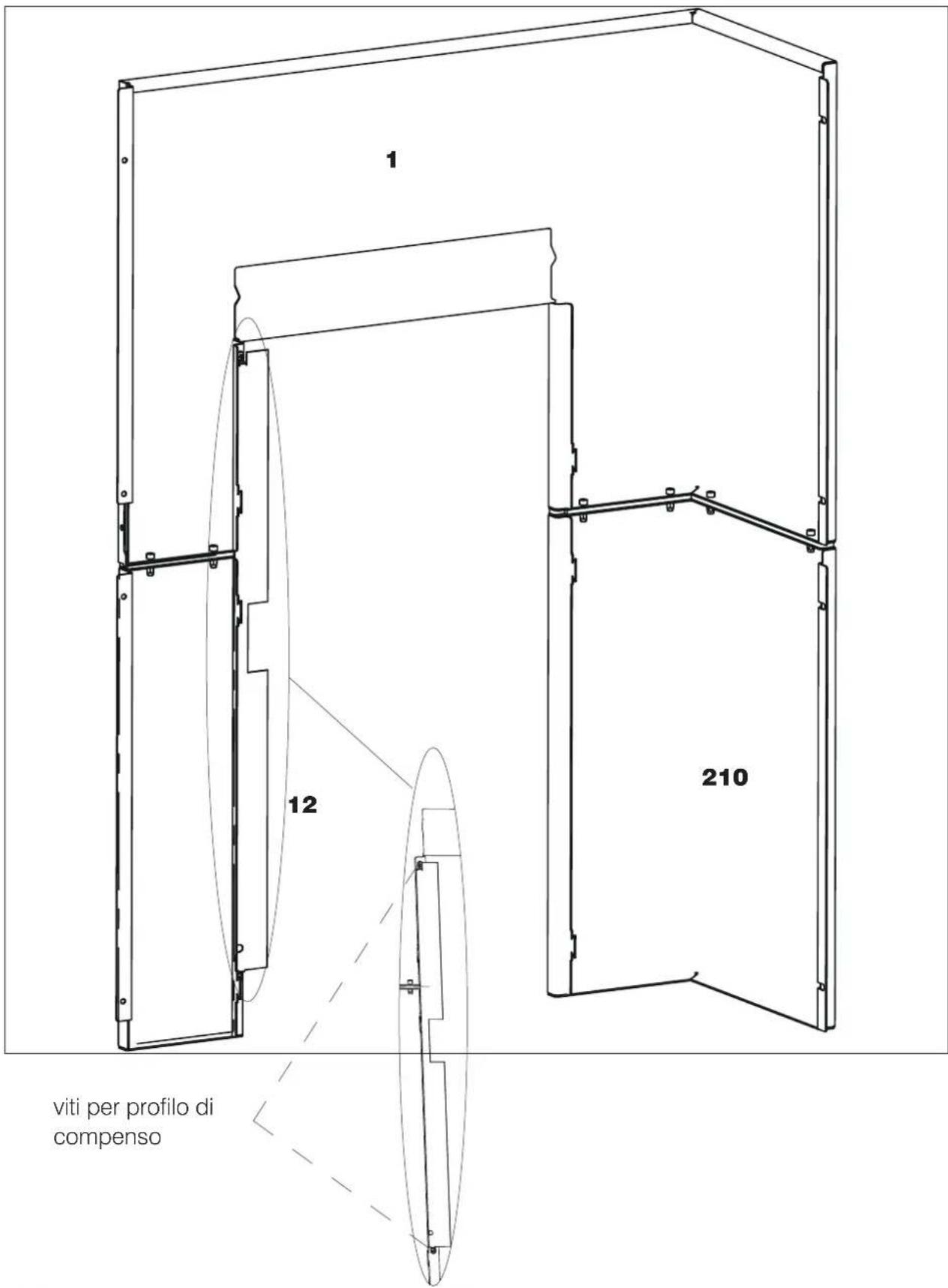
text_image
1 12 210 viti per profilo di compensoINSTALLER
Fitting of the assembled left-hand side panel
natural_image
Technical line drawing of an internal electrical enclosure with visible circuitry and components (no text or labels)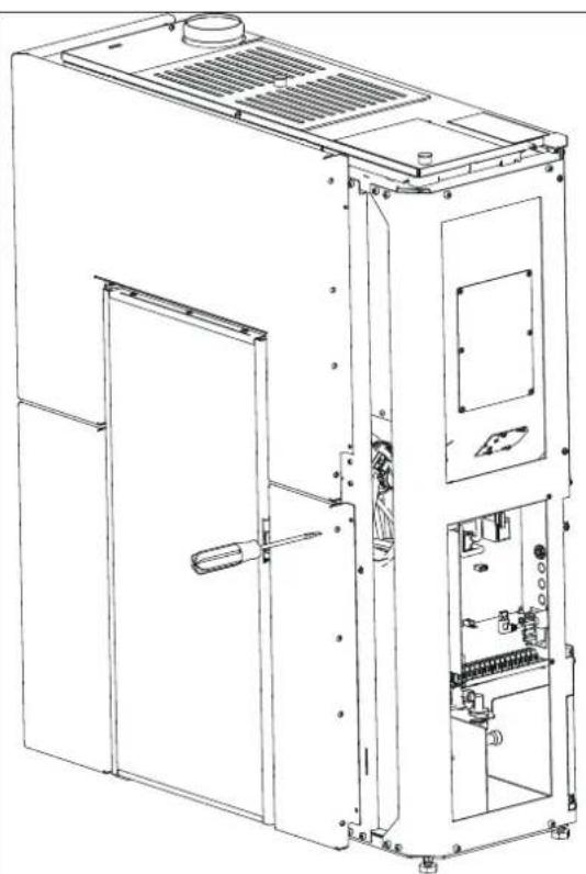
natural_image
Technical line drawing of an industrial machine casing with internal components and mounting brackets (no text or symbols)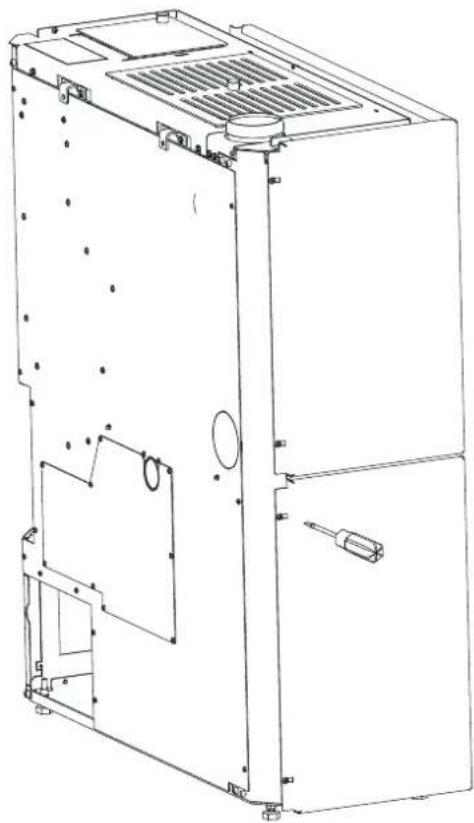
natural_image
Technical line drawing of a multi-chamber refrigerator or air conditioning unit (no text or symbols visible)Assembling the right-hand side panel
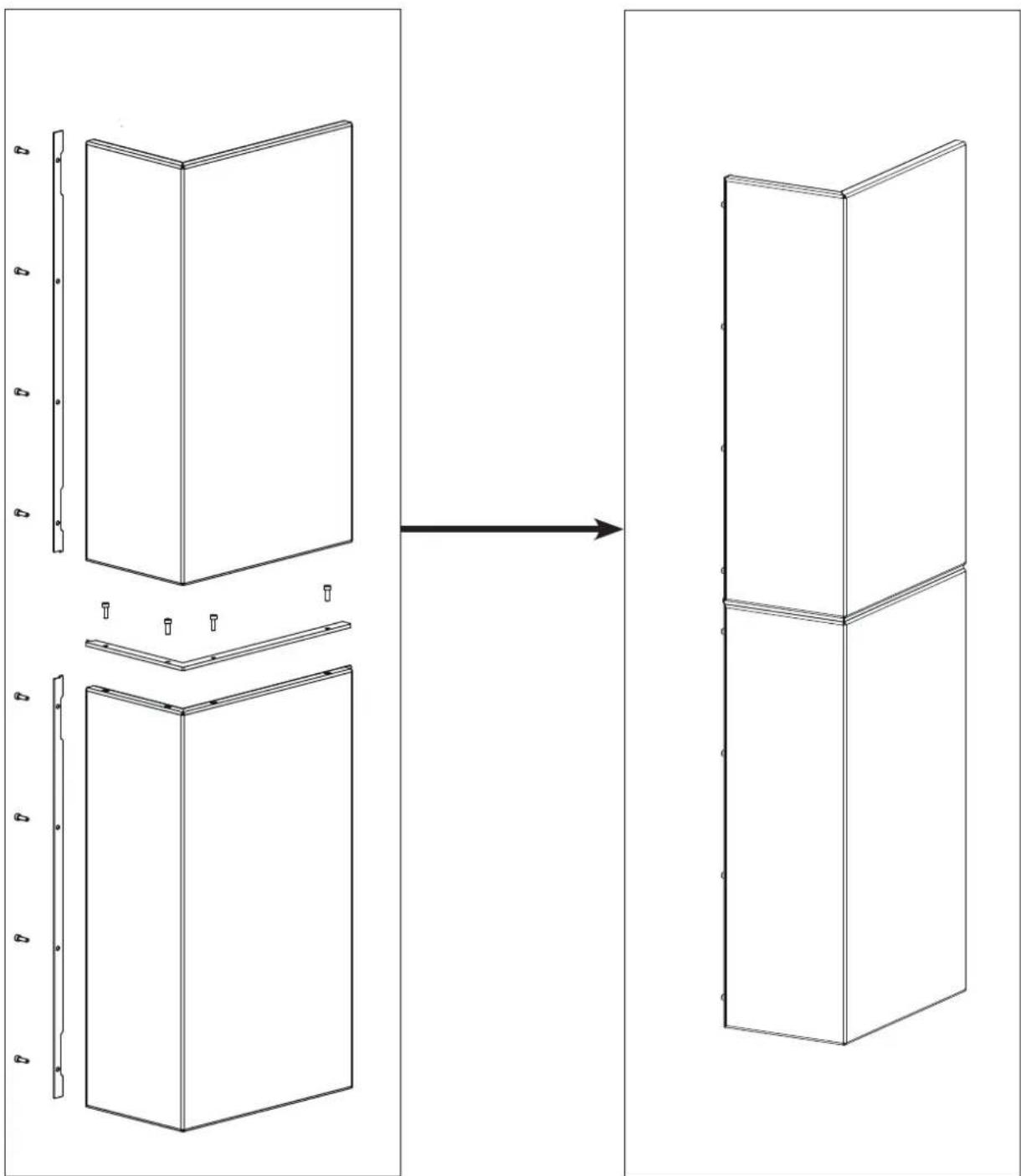
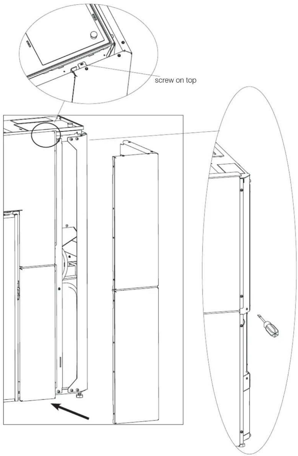
Screw on the top right-hand side panel, the external right-hand profile and the right-hand front profile. Slot the top right-hand side panel. Screw on the central spacers until obtaining the complete right-hand side panel.
natural_image
Diagram showing a structural change from original panel to 3D model, with no text or symbols present.Insert the assembled right-hand side panel.
text_image
screw on topscrew
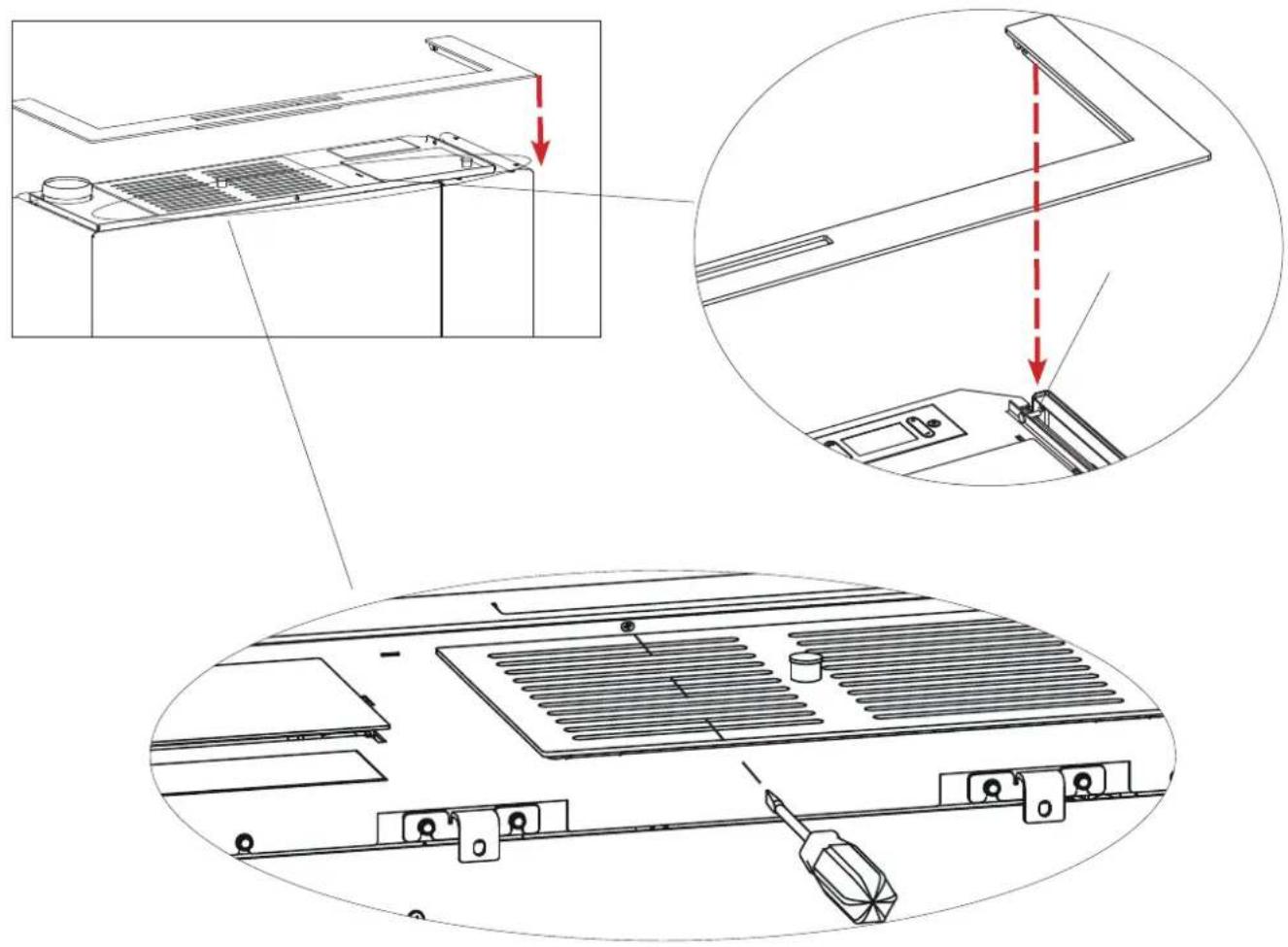
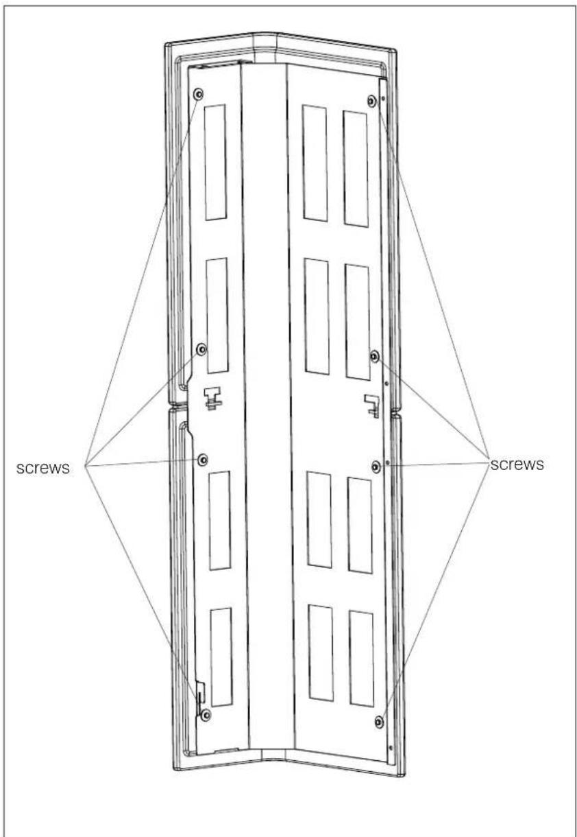
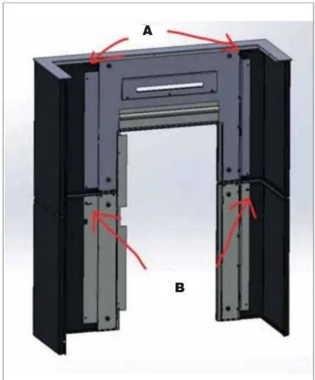
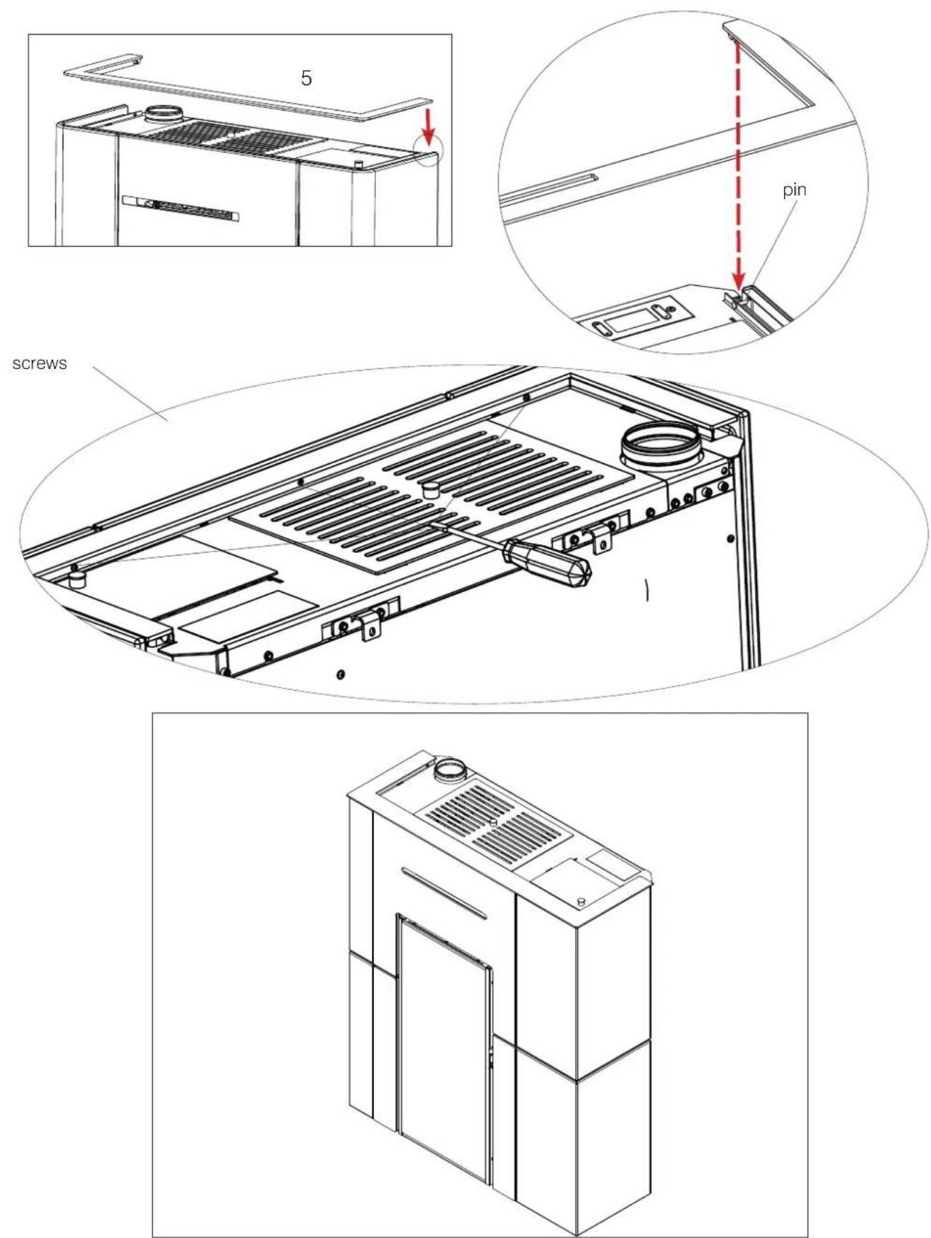
Mounting the aesthetic top edge
Place the aesthetic top edge by slotting it into the two pins to the right and left and fastening it with the 4 screws on the front.
text_image
Technical diagram showing three-step assembly of a server rack with labeled components and red dashed arrows indicating assembly steps.The mounted cladding product appears as shown below.
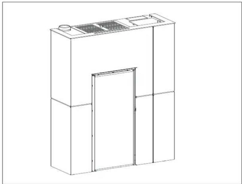
natural_image
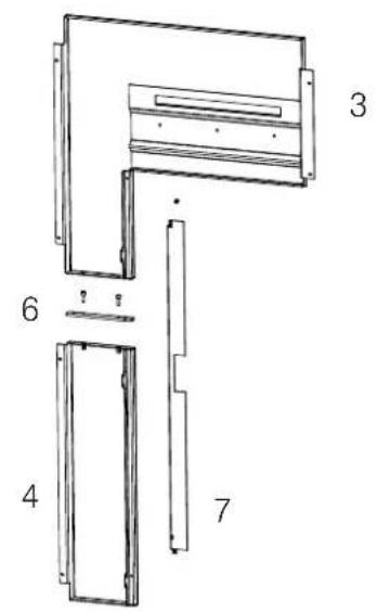
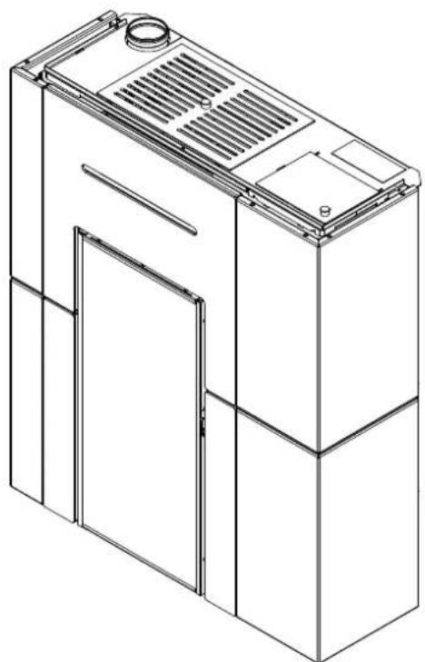
Line drawing of a cabinet or enclosure with a door and ventilation grille (no text or symbols)The Blade H 15 Evo ceramic cladding is divided as shown below:
• a box with the metal parts (A), indicated in the table below (3-4-5-6);
- two boxes (B)-(C) strapped together each containing a ceramic side panel.
| Description Reference in the figures below Quantity | |
| Right-hand ceramic side panel (1) n°1 | |
| Left-hand side panel (2) n°1 | |
| Steel top front panel (3) n°1 | |
| Steel bottom front panel (4) n°1 | |
| Aesthetic top edge (5) n°1 | |
| Filler profile between the top and bottom front panels made of steel | (6) n°1 |
| Filler Profile (7) n°1 | |
| Small hardware |
"Right" and "left" refer to the product when viewed from the front.
The above-mentioned elements, once they have been mounted, will be positioned as shown in the adjacent figure.
The mounting operations are described in the figures appearing on the following pages.
text_image
5 3 1 2 7 4 6
Levelling feet
The product is equipped with feet that can be adjusted with a screwdriver from inside the product BEFORE mounting the claddings.
BEFORE INSTALLING THE CLADDING, SECURE THE PRODUCT TO THE WALL WITH THE BRACKETS PROVIDED TO MAKE SURE IT DOES NOT TIP OVER.
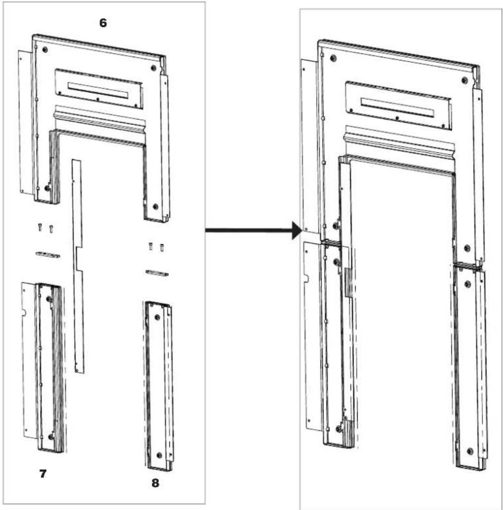
Assembling the right-hand side panel (3 and 4)
text_image
Technical diagram of a door frame assembly with numbered parts labeled 3, 4, 6, and 7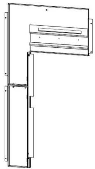
natural_image
Technical line drawing of a mechanical assembly with no visible text or symbols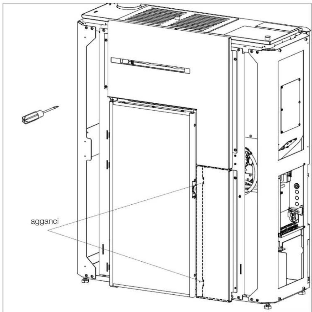
text_image
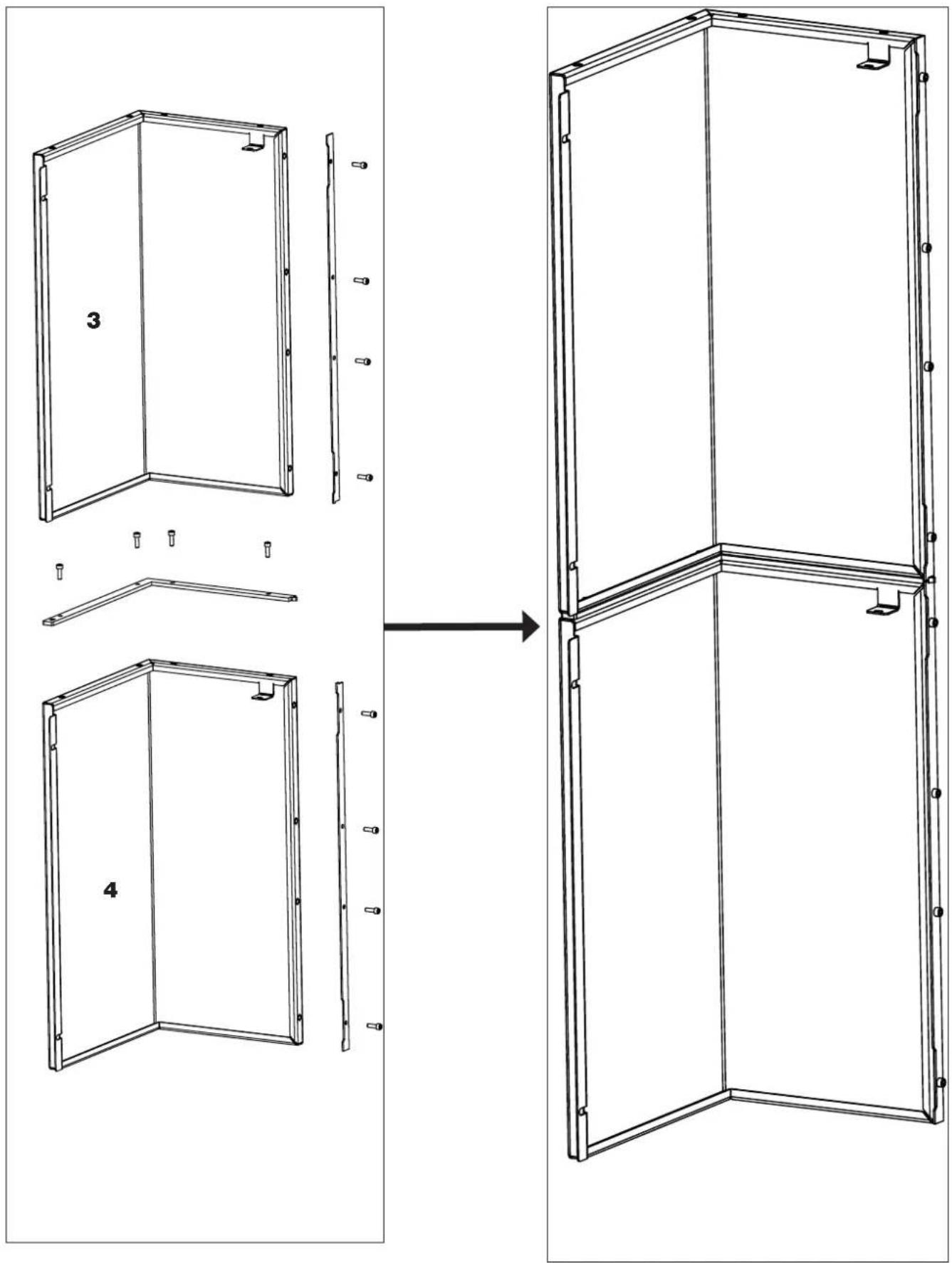
agganciAssembling the side panel (2)
text_image
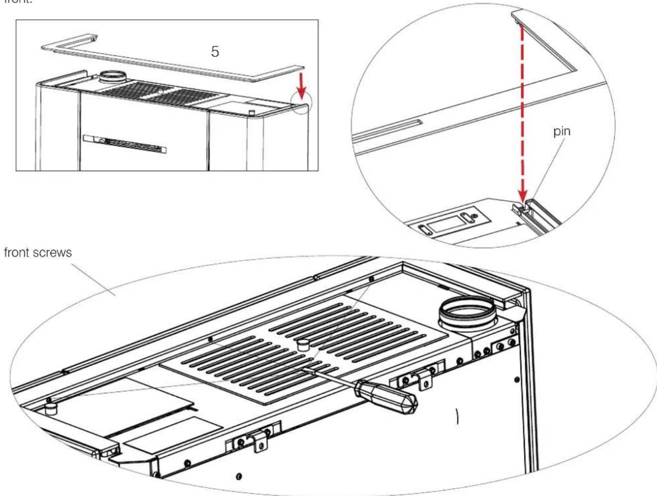
2 fix screws screwsAssembling the side panel (1)
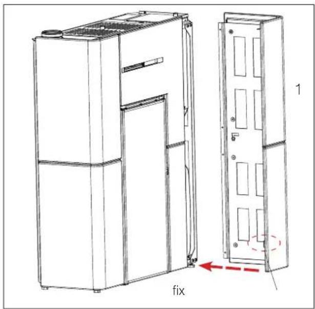
text_image
fix 1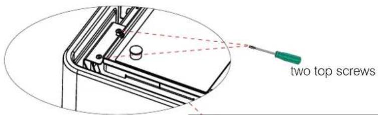
text_image
two top screws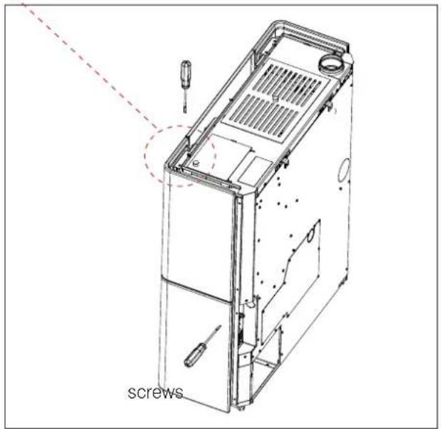
text_image
screws- Regulations

upper slots
where the
ceramic
elements are
screws on
natural_image
Technical line drawing of a mechanical component with an inset view showing a projection or alignment (no text or symbols)
text_image
screws screwsMounting the aesthetic top edge (5)
Place the aesthetic top edge by slotting it into the two pins to the right and left and fastening it with the screws on the front.
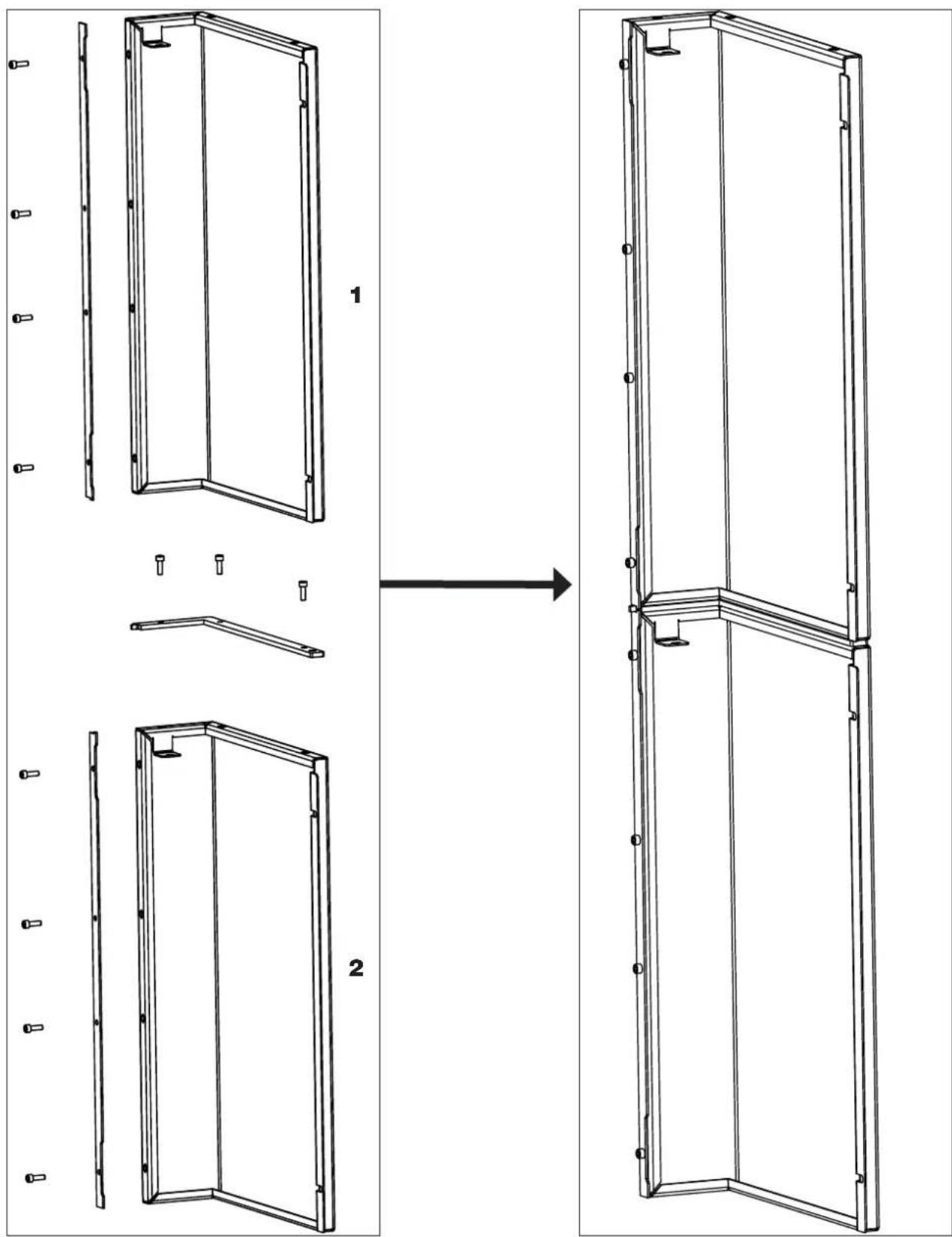
| Description Reference in the figures below Quantity | |
| Left upper panel (1) n°1 | |
| Lower left side (2) n°1 | |
| Right upper panel (3) n°1 | |
| Lower right side (4) n°1 | |
| Aesthetic top edge (5) n°1 | |
| TOp glass (6) n°1 | |
| Bottom right glass (7) n°1 | |
| Bottom left glass (8) n°1 | |
| Filler Profile n°8 | |
| Small metal parts |
"Right" and "left" refer to the product when viewed from the front.
The above-mentioned elements, once they have been mounted, will be positioned as shown in the adjacent figure.
The mounting operations are described in the figures appearing on the following pages.
text_image
Exploded view diagram of a modular wall assembly with numbered components
PRIMA DI MONTARE IL RIVESTIMENTO FISSARE IL PRODOTTO A MURO CON LE STAFFE IN DOTAZIONE PER EVITARE IL POSSIBILE RISCHIO DI RIBALTAMENTO.
- Bend the upper flaps (A) to 90^ .
- Leave the lower fins (B) straight.
text_image
A BAssembling glass
text_image
Technical diagram showing assembly steps of a door frame with labeled components and directional arrowAssembling the side panel
text_image
Technical diagram showing a folding or assembly process with labeled components and directional arrows indicating sequence.Assembling the side panel
text_image
Technical diagram showing assembly steps of a metal frame with labeled components and directional arrows indicating process flow.Fix glass
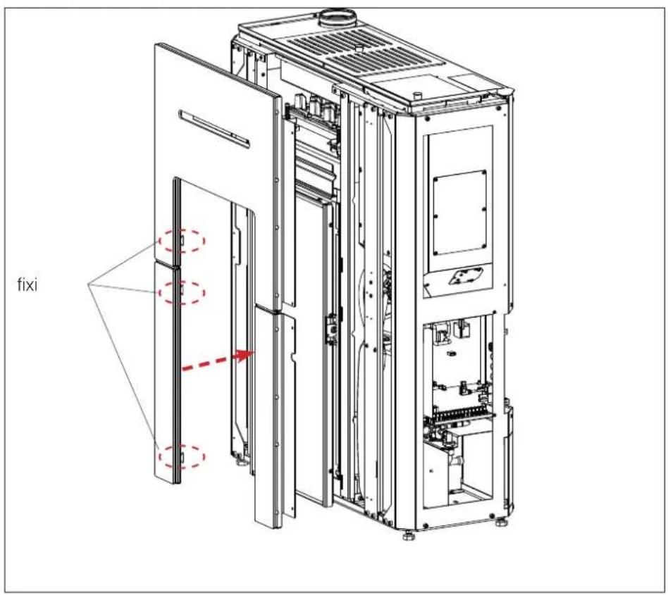
text_image
fixi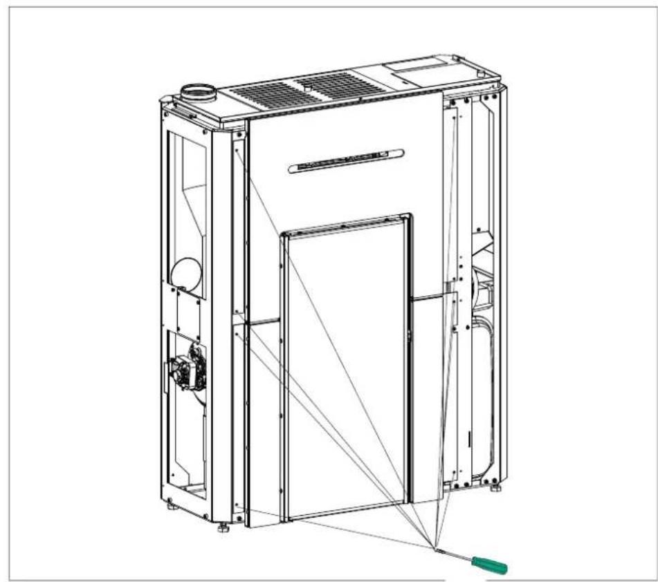
natural_image
Technical line drawing of a mechanical device with internal components and a green tool (no text or symbols)Assembling the left side panel
natural_image
Technical line drawing of a multi-chamber industrial machine or server unit (no text or symbols visible)Assembling the right side panel
natural_image
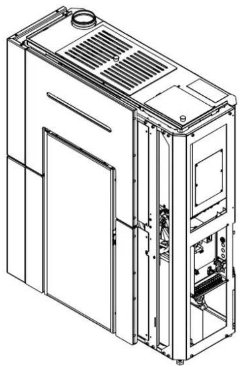
Line drawing of a multi-tiered industrial or kitchen appliance with ventilation grilles and doorways (no text or symbols)Assembling the left side panel (5)
HYDRAULIC CONNECTIONS
The hydraulic connections depend on the type of system.
However, there are a few "general rules".
Below are the reference rules according to the Italian standards:
- The plumbing connections must be made by qualified personnel who can issue documentation certifying the correct installation according to the regulations in force in each country (for example, in Italy pursuant to Ministerial Decree 37/2008 and pursuant to the UNI 10412-2 standard).
- The hydraulic system must operate at a pressure between 1 and 1.5-2 bars at running temperature (hot) in a closed vessel circuit.
- N.B.: the product SHOULD NOT be installed in place of, for example, an open-vessel installed cooker without adjusting the expansion system to closed vessel.
- The presence of a puffer (inertial storage tank) is recommended but not mandatory. Its advantage is that it releases the product from "sudden" requests from the system and can be integrated with other heat sources. It reduces fuel consumption and increases the efficiency of the system.
- The return temperature of water must be higher than at least 50–55°C to prevent condensate from forming. The installer must assess, in relation to the plant, whether anti-condensate pumps or valves are required.
- An accumulator (tank) is needed to heat low-temperature radiant panels and must be installed according to the panel manufacturer's instructions. Radiant panels must not receive water directly from the boiler stove.
- The material used in the circuit must be suitable to withstand overheating.
- The safety valve's relief outlet must be accessible and visible. Waste water must be conveyed via a vertical pipe through a funnel with backflow air vents, at a suitable distance from the point of drainage.
• IT IS FORBIDDEN TO SHUT OFF THE OUTLET
All local, national laws and European Standards must be met in the proper sizing, installation, maintenance
and use of the appliance. Refer to local codes in each country for installation and for anything not specifically mentioned.
- Check that the hydraulic system has been properly arranged and that it is equipped with a sufficiently large expansion vessel for guaranteeing its safety. The presence of the vessel incorporated in the boiler stove does NOT guarantee adequate protection against thermal expansion of the water in the entire system. Therefore, installers should assess whether an additional expansion tank is needed, depending on the type of system.
- The installer must assess, on the basis of the type of water and system, whether water conditioners are required pursuant to the UNI 8065 standard (water treatment in heating systems for civil use).
- Direct plumbing to the radiators prevents proper operation, owing to the small diameter of their pipes.
Fill the system via the filling valve (we recommend not exceeding a pressure of 1.5 bar).
During the filling phase, bleed the pump and the relief valve.
Pressure gauge
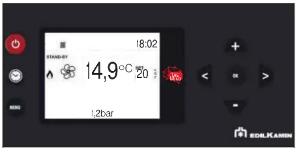
The boiler stove has an electronic system for reading the water pressure. There is no analogue pressure gauge. The water pressure is shown on the display, in the middle as shown in the diagram below.
text_image
18:02 STAND-BY 14,9°C SET 20 MRS 1,2bar EDILKAMINAny disabling can be made into the installer parameters.

The return water temperature must be at least 50-55° C to avoid condensation. An anti-condensation system is essential, under penalty of forfeiture of warranty, as installation is not correct and non-compliant.
The product is equipped with:
- pump
- safety valve
- expansion vessel (suitably sized for the volume of water of the primary circuit)
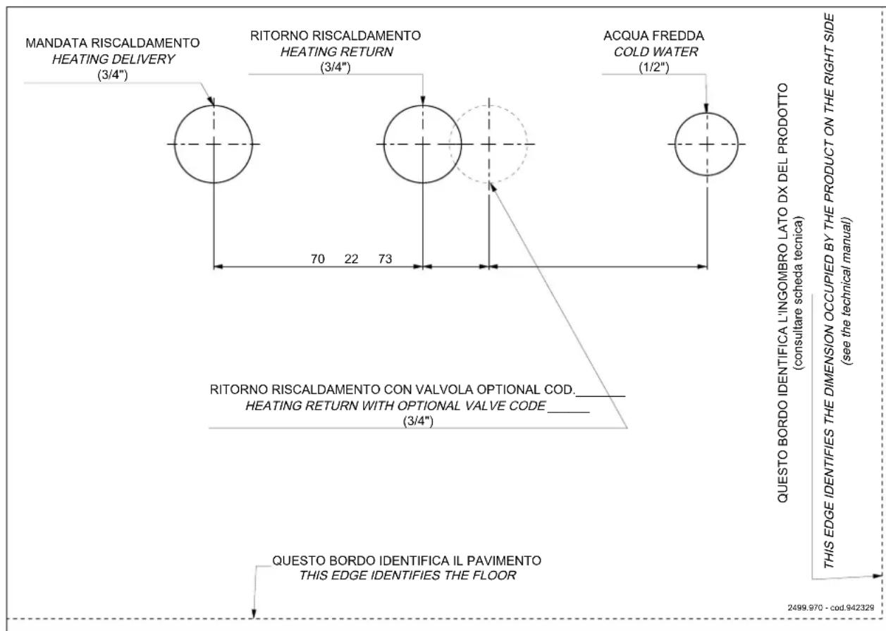
Template for plumbing fittings in mm
text_image
MANDATA RISCALDAMENTO HEATING DELIVERY (3/4") RITORNO RISCALDAMENTO HEATING RETURN (3/4") ACQUA FREDDA COLD WATER (1/2") 70 22 73 RITORNO RISCALDAMENTO CON VALVOLA OPTIONAL COD. HEATING RETURN WITH OPTIONAL VALVE CODE (3/4") QUESTO BORDO IDENTIFICA IL PAVIMENTO THIS EDGE IDENTIFIES THE FLOOR QUESTO BORDO IDENTIFICA L'INGOMBRO LATO DX DEL PRODOTTO (consultare scheda tecnica) QUESTO BORDO IDENTIFICA L'INGOMBRO LATO DX DEL PRODOTTO (consultare scheda tecnica) THIS EDGE IDENTIFIES THE DIMENSION OCCUPIED BY THE PRODUCT ON THE RIGHT SIDE (see the technical manual) 2499.970 - cod.942328PUMP SPECIFICATIONS
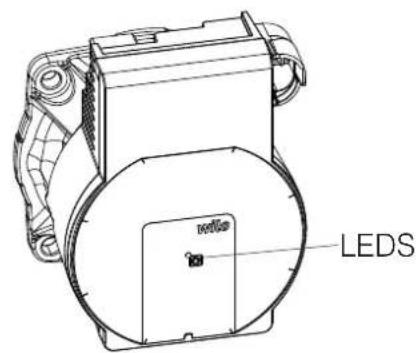
text_image
LEDSThe pump has no adjustment devices.
Adjustments are made via the electronic circuit board: it "starts" at minimum speed and makes adjustments based on the water temperature trend.
The table below shows the LED signals and their descriptions.
| LED MEANING CAUSE SOLUTION | |||
| Steady green Pump running Normal operation | |||
| Flashing green light Pump in stand-by mode Normal operation | |||
| Steady red LED | Stall Pump stalled | Contact the TAC | |
| Contact/winding Defective winding | |||
| Flashing red LED | Under-/over-voltage Supply voltage too low/high | Check the supply voltage/contact the TAC | |
| Excessively high modu temperature | Motor board temperature high | ||
| Flashing red/green light | Turbine-based operation | The pump is not powered but the hydraulic system is fed by other sources | Check the mains voltage/ter pressure and environmental conditions/contact the TAC |
| Dry operation | Air in the pump | ||
| Overload | The motor runs with difficulty | ||
INSTALLATION
POSSIBLE SYSTEM DESIGNS
The installer can configure 4 types of systems.
The relative probe inputs are already configured automatically.
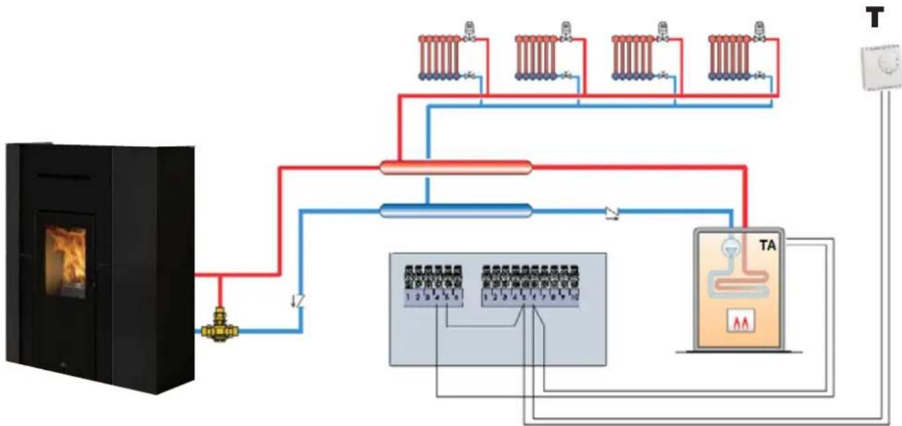
DIRECT HEATING (with optional boiler)
IT is configuration "O" in the parameters.
flowchart
graph TD
    A["Beef/Box"] --> B["Heater"]
    B --> C["Heat Exchanger"]
    C --> D["Temperature Sensor 1"]
    C --> E["Temperature Sensor 2"]
    C --> F["Temperature Sensor 3"]
    C --> G["TA Unit"]
    D --> H["Return Line"]
    E --> H
    F --> H
    G --> H
    H --> I["Power Supply"]
    style A fill:#f9f,stroke:#333
    style I fill:#ccf,stroke:#333
The product adjusts in relation to the water temperature and switches on/off on the basis of the room temperature (probe or thermostat T) or, at the discretion of the installer, on the basis of the water temperature.
NOTE:
In Italy the systems must be separated if the power exceeds 35 kW.
NOTE:
Given the product's power, we do not recommend using it to produce instantaneous domestic hot water.
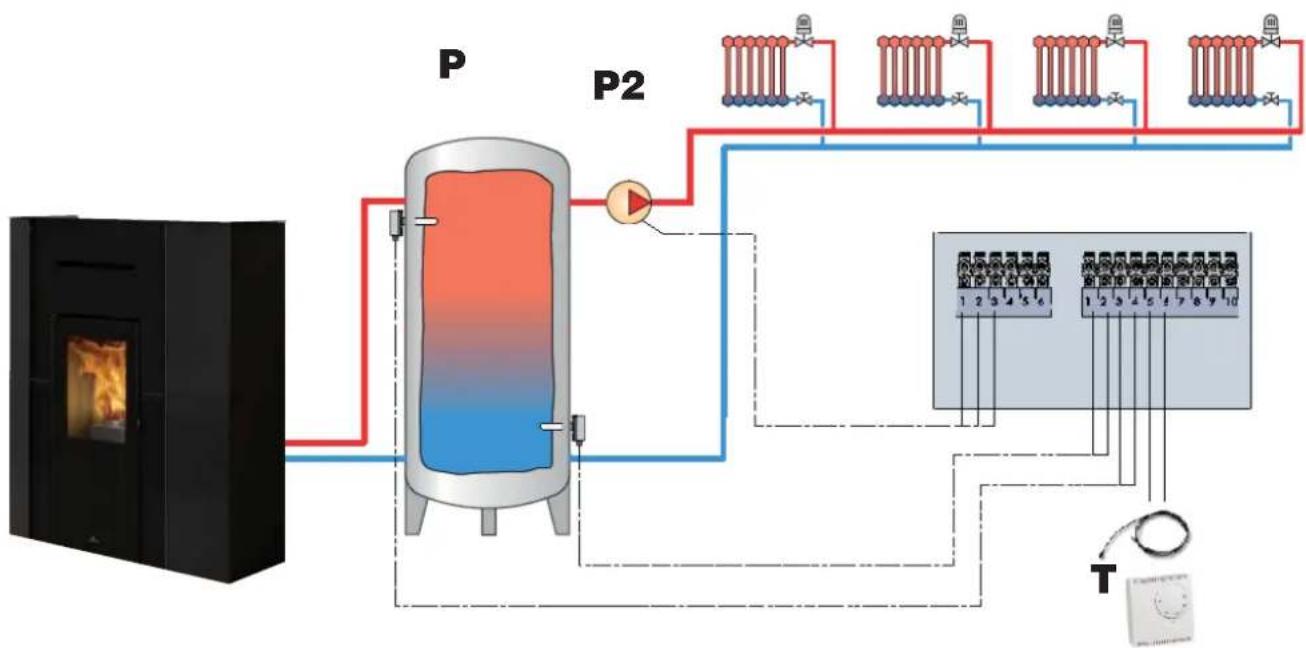
HEATING WITH PUFFER (inertial storage tank)
IT is configuration "1" in the parameters.
flowchart
graph TD
    A["Heat Input"] --> B["Condenser"]
    B --> C["Pump"]
    C --> D["Condenser"]
    D --> E["Temperature Monitoring System"]
    E --> F["Output 1-10"]
    style A fill:#f9f,stroke:#333
    style B fill:#ccf,stroke:#333
    style C fill:#cff,stroke:#333
    style D fill:#ffc,stroke:#333
    style E fill:#cfc,stroke:#333
    style F fill:#fcc,stroke:#333
The product adjusts in relation to the water temperature and switches on/off on the basis of the PUFFER temperature (P). The room temperature measured by the thermostat (T) adjusts the secondary circuit pump (P2)
NOTE:
In Italy the systems must be separated if the power exceeds 35 kW.
NOTE:
Given the product's power, we do not recommend using it to produce instantaneous domestic hot water.
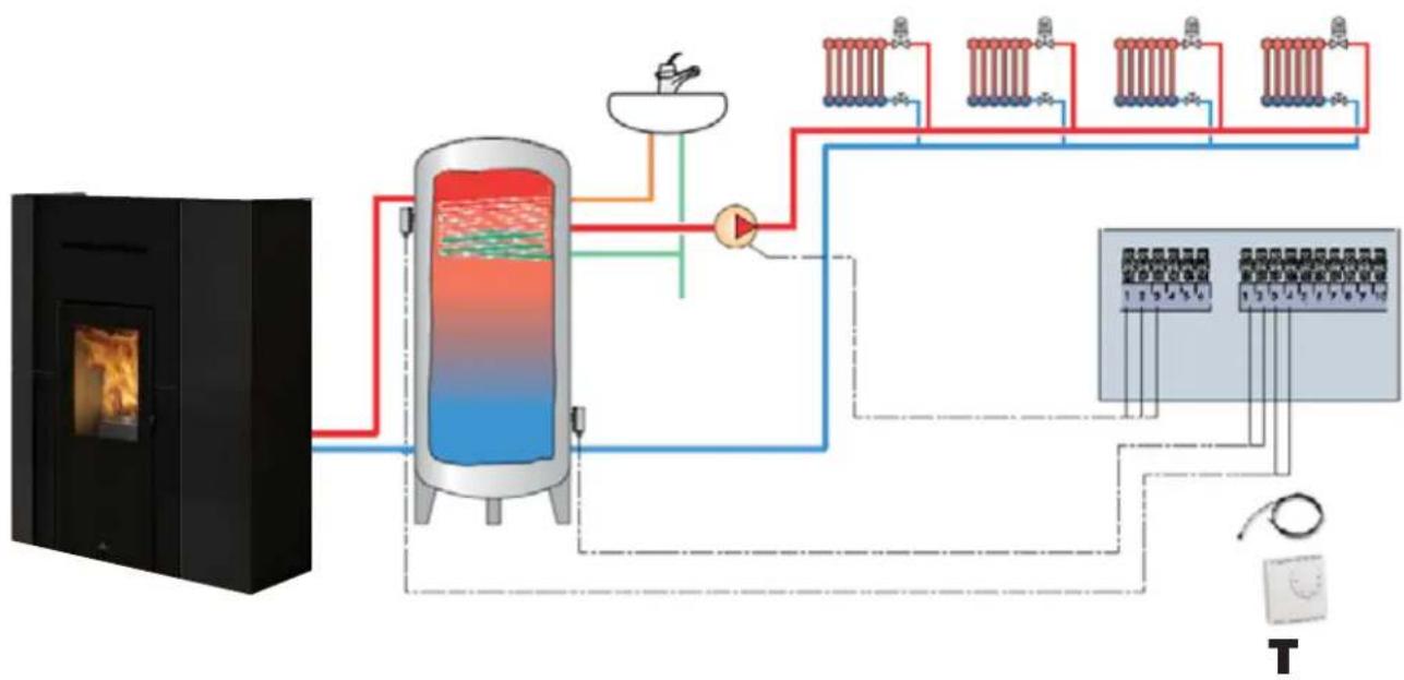
HEATING WITH DHW STORAGE TANK (with optional boiler)
IT is configuration "2" in the parameters.
flowchart
graph TD
    A["Beef Boiler"] --> B["Reactor with Heat Exchanger"]
    B --> C["Heater with Heat Exchanger"]
    C --> D["Control Panel"]
    D --> E["Output 1-10"]
    D --> F["Output 1-25"]
    D --> G["Output 2-30"]
    D --> H["Output 3-40"]
    D --> I["Output 4-50"]
    D --> J["Output 5-60"]
    D --> K["Output 6-70"]
    D --> L["Output 7-80"]
    D --> M["Output 8-90"]
    D --> N["Output 9-100"]
The product has the main aim of heating the domestic hot water storage tank.
The product adjusts in relation to the water temperature and switches on/off on the basis of the room temperature (probe or thermostat T) or, at the discretion of the installer, on the basis of the water temperature.
NOTE:
In Italy the systems must be separated if the power exceeds 35 kW.
NOTE:
Given the product's power, we do not recommend using it to produce instantaneous domestic hot water.
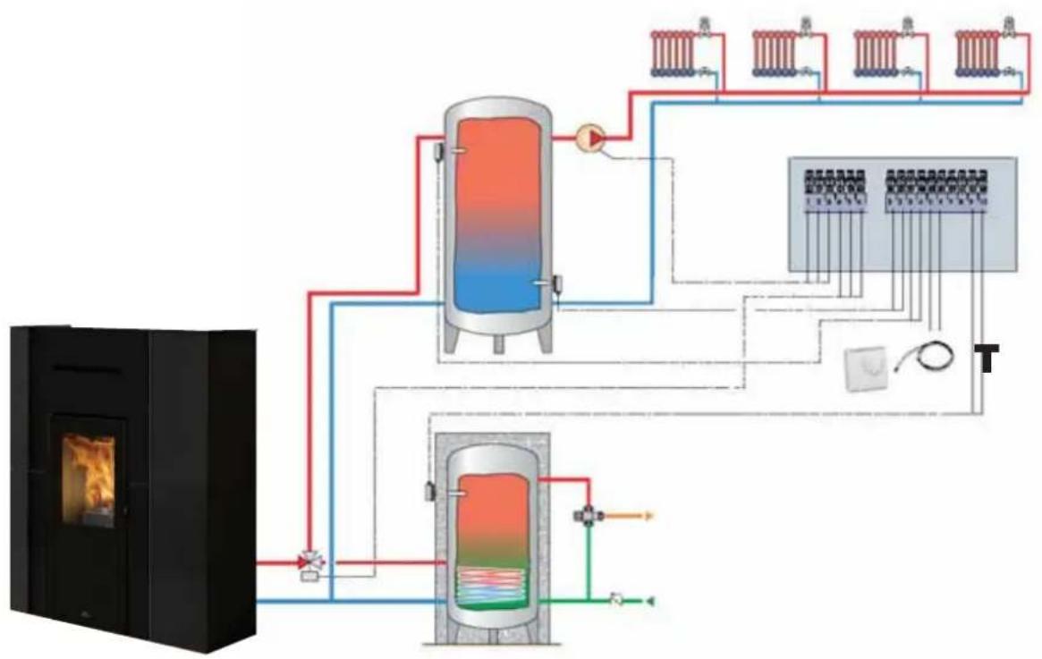
HEATING WITH PUFFER (inertial storage tank) AND BOILER (domestic hot water storage tank)
IT is configuration "3" in the parameters.
flowchart
graph TD
    A["Large furnace"] --> B["Heat Exchanger"]
    B --> C["Three-tiered storage unit"]
    C --> D["Control Valve 1"]
    C --> E["Control Valve 2"]
    C --> F["Control Valve 3"]
    C --> G["Control Valve 4"]
The product has the main aim of heating the domestic hot water storage tank.
The product adjusts in relation to the water temperature and switches on/off on the basis of the PUFFER temperature (P).
The room temperature measured by the thermostat (T) adjusts the secondary circuit pump (P2)
NOTE:
In Italy the systems must be separated if the power exceeds 35 kW.
NOTE:
Given the product's power, we do not recommend using it to produce instantaneous domestic hot water.
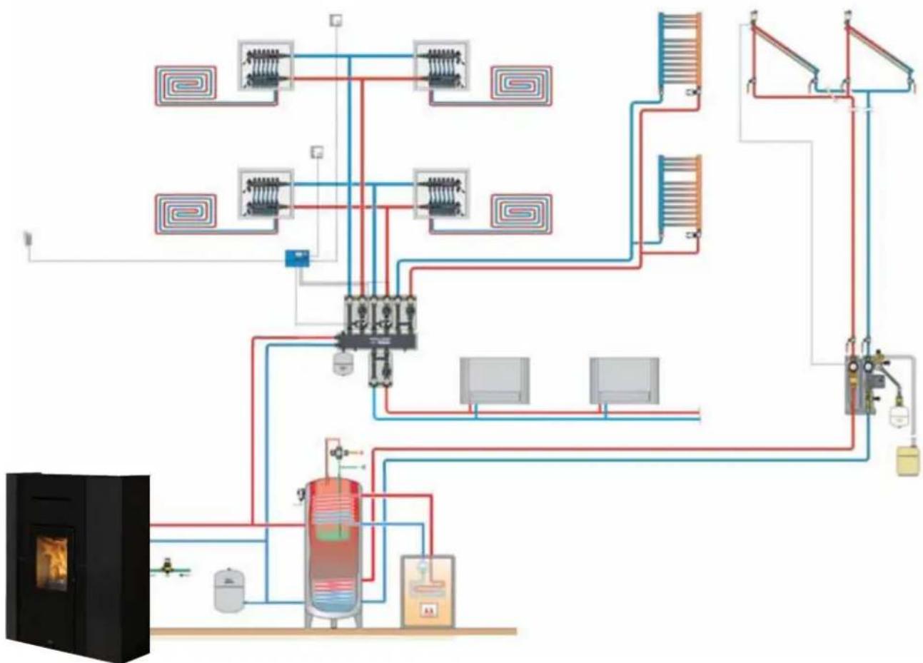
In addition to the pre-set configurations, the product can be installed on integrated systems (example below) with probes and thermostats.
flowchart
graph TD
    A["Heater锅炉"] --> B["热泵"]
    B --> C["换热器"]
    C --> D["阀门"]
    D --> E["换热器"]
    E --> F["阀门"]
    F --> G["换热器"]
    G --> H["阀门"]
    H --> I["换热器"]
    I --> J["阀门"]
    J --> K["换热器"]
    K --> L["阀门"]
    L --> M["换热器"]
    M --> N["阀门"]
    N --> O["换热器"]
    O --> P["阀门"]
    P --> Q["换热器"]
    Q --> R["阀门"]
    R --> S["换热器"]
    S --> T["阀门"]
    T --> U["换热器"]
    U --> V["阀门"]
    V --> W["换热器"]
    W --> X["阀门"]
    X --> Y["换热器"]
    Y --> Z["阀门"]
NOTE:
In Italy the systems must be separated if the power exceeds 35 kW.
NOTE:
Given the product's power, we do not recommend using it to produce instantaneous domestic hot water.
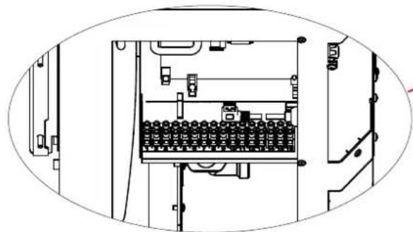
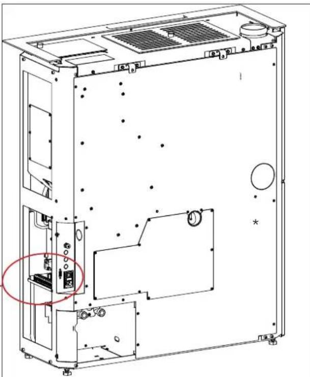
TERMINAL BOARD
On the side there is a bracket with 2 terminal boards*.
One terminal board (10 poles) is low voltage and the other (6 poles) is high voltage.
Examples = of = possible = connection = configurations = are given below.
natural_image
Technical line drawing of an electrical enclosure with internal components and wiring (no text or symbols)The poles are numbered on the product as below
natural_image
Technical line drawing of an internal device casing with mounting holes and ventilation grilles (no text or symbols)low voltage terminal board
| No. of POLES | POSSIBLE CONNECTIONS NOTES | |
| 1/2 | NTC analogue input 10 k | for example, for a second probe for accumulator tank or boiler for domestic hot water or for an external probe for climatic curve |
| 3/4 NTC | probe/puffer tank thermostat | |
| 5/6 NTC | probe (standard) / room thermostat | the room probe is supplied already wired as standard |
| 7/8 | Home Automation Input.This is an input which receives all home automation contacts | |
| 9/10 Probe | be for domestic hot water boiler |
high voltage terminal board
| No. of POLES | POSSIBLE CONNECTIONS NOTES | |
| 11/12/13 | Electrical connection for booster/secondary pump (Earth, Neutral/Phase) | |
| 14/15/16 | External solenoid valve (Common, Normally Closed, Normally Open)4 = Common5 = Normally Closed6 = Normally Open | The technician can configure the setting for the connection on pins 4 and 5 of an output contact for an external boiler or remote alarm. |
REMARKS ON INSTALLATION
Note that:
- installation must be carried out by authorised The surfaces of the building adjacent to the product technical personnel; must be protected against overheating.
- the appliance must be installed and operated. The insulation to be used will depend on the type of in compliance with local and national law and surface in question.
The surfaces of the building adjacent to the product must be protected against overheating.
The insulation to be used will depend on the type of surface in question.
European regulations. The applicable Italian regulation is UNI 10683;
- if installed in a condominium, the appliance must be approved by the administrator.
Here are a few general instructions, although these do not obviate the need to comply with local regulations and do not affect the installer's liability for installation.
Checking the suitability of the installation space
• The room must have a volume of at least 15 m ^3
- The floor must be able to bear the weight of the product and its accessories.
- Level the product (the product is provided adjustable feet).
- The appliance cannot be installed in the room as other equipment which draws air combustion from the room itself or any area with an explosive atmosphere. Any extraction fans operating in the same room or area as the product may affect its draught.
- In Italy, check the compatibility pursuant to UNI 10683 and UNI 7129 in the presence of gas-fired products.
Protection from heat and safety clearances.
The appliance must be installed in accordance with the following safety instructions:
- no flammable materials may be kept less than 5 cm to the sides.
- no flammable materials may be kept within 80 cr from the front of the appliance.
If connected to a wooden or otherwise flammable wall, the smoke exhaust pipe must be insulated appropriately.
If installed on flammable or combustible floors, or floors not able to withstand its load, place steel or glass plates beneath the stove to distribute the load.
Information on the product's positioning
with the product is designed to operate in all climate conditions. In special circumstances, such as strong
samwind, the safety devices may intervene to switch the forappliance off.
Contact the authorised Edilkamin Technical Assistance Centre.

The infiltration of condensation water through the chimney is to be avoided at all costs. An anti-condensation ring must be fitted where necessary (please contact your chimney sweeper). Damages caused by condensation water are not included in warranty.
FLUE SYSTEM(Smoke duct, flue and chimney pot)
This chapter has been drawn up pursuant to European regulations EN 13384, EN 1443, EN 1856 and 1457. The installer must observe both these and any other local regulations.
This manual does not in any way substitute such regulations.
The product must be connected to a smoke exhaust system which ensures that the smoke produced by combustion is expelled in complete safety.
Before positioning the appliance, the installer must check that the flue is suitable.
SMOKE DUCT, FLUE
The smoke duct(which connects the combustion chamber smoke outlet with the flue inlet) and the flue itself must, among other regulatory requirements:
- receive the smoke from a single product (the outlets of multiple appliances may not be conveyed into a single flue)
• be routed vertically for the most part
• have no downwards sloping sections - preferably have a circular internal cross section, or with a ratio of the sides of less than 1.5
- terminate at roof level with a proper chimney pot: the flue may not discharge directly on the wall or into an enclosed space, even if the space in question is open to the sky
- be made of material with rated fire reaction class
A1 as per UNI EN 13501 or analogous national regulations
• be certified, with a chimney plate if metal - be of uniform cross section or vary in cross section only immediately after the outlet, not at some mid point of its length
THE SMOKE DUCT
Besides the general prescriptions applicable to the smoke duct and flue, the smoke duct:
EN may not be made of flexible metal material
- must be insulated, if routed through unheated areas or outdoors - on must not be routed through rooms where the installation of combustion heat generators is prohibited, there is risk of fire, or which cannot be by inspected
- must enable the recovery of soot and be open for inspection
- must have at most 3 bends with a maximum angle of 90^
- if there is a horizontal section, it must have maximum length of 3 metres, depending on the draught Note, in any case, that long sections encourage the accumulation of dirt and are harder to keep clean.
The correct sizing of the flue system must be made by the installer.

THE FLUE OUTLET ∅ IS NOT THAT OF THE CHIMNEY SYSTEM, WHICH MUST BE SIZED IN ACCORDANCE WITH NATIONAL AND LOCAL STANDARDS
FLUE
Further to the general prescriptions, the flue must
• only be used to discharge smoke
- be correctly sized to satisfy the requirements smoke discharge (EN 13384-1)
- must preferably be insulated, in steel with a circular internal section. If rectangular, the corners have a radius of not less than 20 mm, with a ratio of the internal dimensions of <1.5
- must normally be at least 1.5 metres in length
- must have a constant cross section
- must be waterproof and thermally insulated to ensure proper draught
- preferably provide a collection chamber for unburnt residues and condensates
- if pre-existing, must be clean, to prevent fire hazards
- in general, we recommend fitting a tube inside the existing masonry chimney if its diameter is greater than 150 mm. This recommendation is purely indicative; the installer must assess the actual situation on-site after measuring the draught.
Besides the general prescriptions, the buried system must:
• operate in negative pressure;
- be inspectable;
• comply with local regulations.
must:
- be windproof
• have an internal cross-sectional area equivalent to that of the flue and a smoke outlet at least double that of the interior of the flue - extend beyond the back flow zone (in Italy, refer to UNI 10683 point 6.5.8.)
- allow for maintenance of the chimney For dual flues (which should be spaced at least 2 m apart), the chimney pot receiving the smoke from the solid fuel appliance or the pot on the higher must be at least 50 cm higher than the other
COMBUSTION AIR INTAKE
In general, we suggest two ways to ensure a proper flow of combustion air. The air must be drawn from outside*
Please remember to also ensure air exchange for heating and glass cleaning air, etc.
must
Indirect air intake
The product draws air from outside through a hole in idae rear.
Install an air outlet at floor level with an effective surface area (net of the screen or other protections) of at least 80 cm ^2 (10 cm in diameter).
To prevent draughts, we recommend installing the intake behind the product or behind a radiator.
Installing it in front of the appliance will create unpleasant draughts.
Direct air intake \*\*
Install an air intake of effective surface area (net of the mesh or other protective equipment) equal to the cross section of the air intake at the back of the product.
Connect the air intake to the appliance's air intake with a pipe that may also be flexible. Increase the diameter of the pipe if the pipe is not smooth: assess any load loss.
We recommend not exceeding a 3 m length, taking into account the flue draught. For each curve, up to a maximum of two curves, the length should be reduced by 1m. Assess whether or not to increase the diameter of the pipe.
*The air may be drawn from an adjacent room only if:
- the flow is taken from permanent and unobstructed openings communicating with the outdoors;
- the air pressure in the adjacent room is never lower than that of the outdoor pressure;
- the adjacent room is not a garage, subject to fire hazard, a bathroom or a bedroom;
- the adjacent room is not a shared room in the storecondominium.
In Italy, UNI 10683 provides that ventilation is sufficient even if a pressure difference between the outdoors and indoors of no more than 4 PA is guaranteed (UNI EN 13384-1). The installer who issues the declaration of conformity is responsible for ensuring these conditions.
**Direct connection to the air intake will not make the product airtight. It is therefore necessary to additionally ensure an air intake from within the room where the product is installed (i.e. for cleaning the glass)
CHECKING THE ELECTRICAL
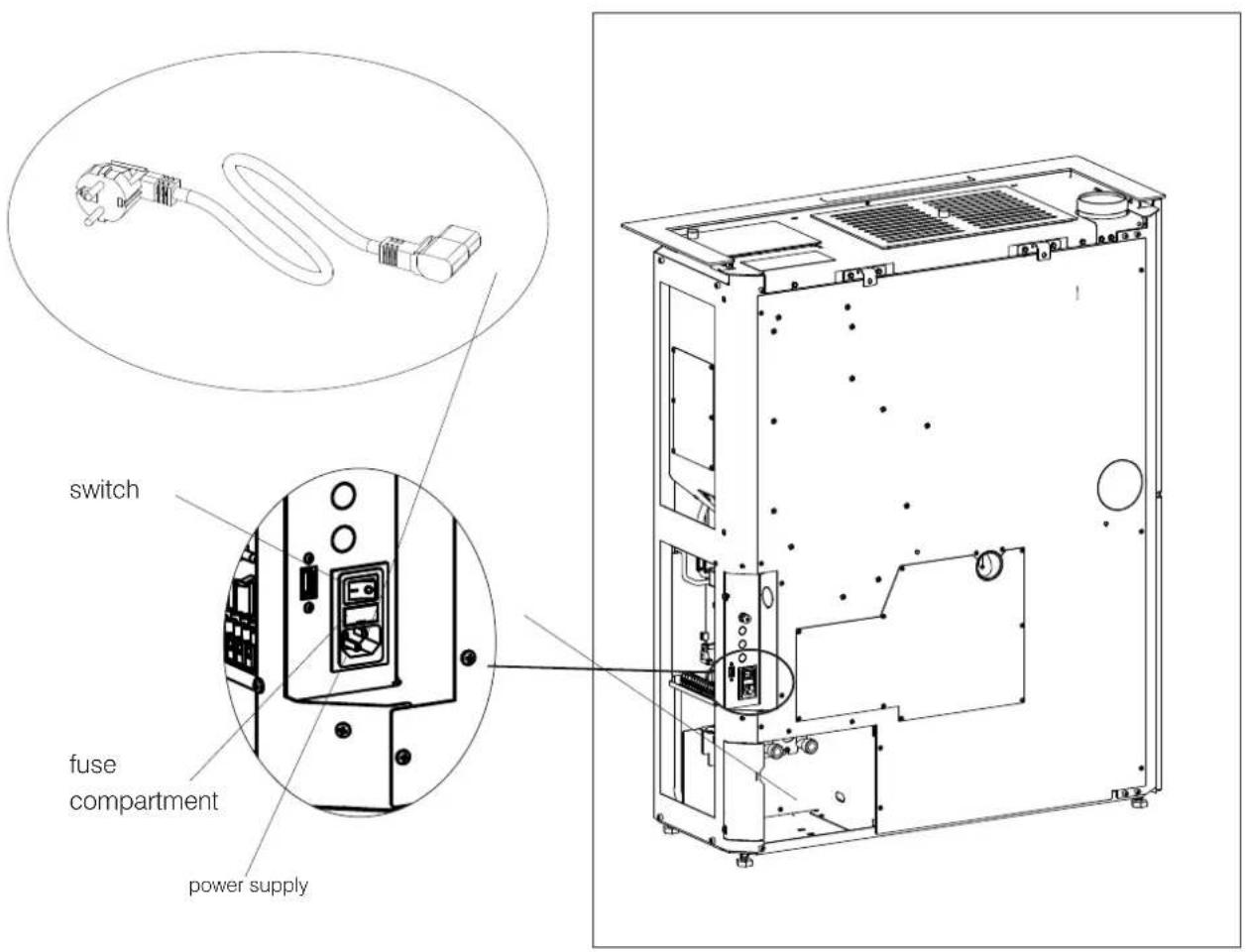
CONNECTIONS (the power outlet must be located in an easily accessible position)
The product is supplied with an electrical power cord for connection to a 230 V 50 Hz socket, preferably one equipped with a residual-current device.
Variations in voltage of more than 10% can jeopardise its operation.
The electrical system must be compliant; check the operation of the earth in particular.
Edilkamin is not responsible for malfunctions resulting from an improperly earthed system.
The power line must be of adequate section for the power of the appliance.
The power cable must not come into contact with the flue or other hot parts of the stove.
Power up the product by setting its switch from 0 to 1.
There is one fuse on the socket with switch located at the rear of the product.
text_image
switch fuse compartment power supply
FIRST IGNITION (COMMISSIONING) PHASES
- Make sure you have read and understood this manual.
- Switch it on ONLY with the claddings mounted on.
- Remove all flammable materials from the appliance (manuals, labels, etc.). In particular remove any labels from the glass.
- Make sure the technician has carried out first ignition for the product, and also filled the pellet reservoir for the first time.
FUEL
Use Class A1 wood pellets conforming to the UNI EN ISO 17225-2 standard or similar local regulations envisaging, for example, products with the following characteristics:
diameter 6 mm
length 3-4 cm
humidity <10 %
For reasons of safety and environmental compatibility, DO NOT burn, among other, plastic, painted wood, coal or bark. Do not use the stove as an incinerator.
natural_image
A black-and-white photo of a bag filled with granular material, no visible text or symbols.
On first ignition, there may be a slight smell of paint, which will disappear in a short time.
It is recommended to run the product at full power, with open windows during the first few days.

VENT
During normal operation the stove is vented automatically. The need for a manual vent for the system can only be assessed by the technician during commissioning.

As with all appliances, this product heats up and cools down during the various operating phases.
This implies normal expansion movements.
These expansion movements may cause slight adjustment noises that cannot constitute grounds for complaints.

CAUTION
Using fuels other than those specified can damage the appliance.
Product will also settle down during the first days of operation.
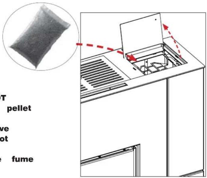
LOADING PELLETS INTO THE TANK
To access the tank, open the lid. *
text_image
T pellet ve ot fume
When the boiler stove is hot, DO NOT MAKE CONTACT between the pellet bag and the top grille.
Use the glove when loading the stove while it operates and is therefore hot to the touch.
Take care not to touch the fume exhaust pipe when hot.

When the stove is hot, DO NOT PLACE the bag of pellets onto it.
Use the glove when loading the stove while it operates and is therefore hot to the touch.
OPERATION
| Mode Settable parameters | |
| AUTOMATIC • | desired room temperature• ventilation level * |
| CRONO • desired room temperature, selected per day of the week• ventilation level* | |
The product also has the following supplementary functions.
| Function | Modes in which it can be activated | What it does |
| Stand-By | automatic crono | when the desired temperature is reached, the product switches off and then back on again when the temperature drops |

text_image
THE MINDINTERFACE
The product can be managed alternatively as follows
STANDARD
• DISPLAY: useful for all functions, located on the product
• The Mind APP : useful for all functions at home with direct connection or outside the home with internet connection and registration
By purchasing the Edilkamin optional elements:
• VOICE CONTROL SYSTEMS: Alexa or Google Home
OPTIONAL ELECTRICAL CONNECTIONS
A terminal board is present on the product (accessible by removing the covering, with electricity off and only by qualified technicians).
DEPENDING ON THE TYPE OF SYSTEM, THE INSTALLER CAN CONNECT PROBES OR THERMOSTATS FOR THE ADJUSTMENT OF THE PRODUCT ACCORDING TO DIFFERENT SIZES.
In case of connection of probes or thermostats on the room inputs, the relevant parameters must be set in the Technical Menu of the appliance.

We recommend, at the end of installation and commissioning, to check all the daily operations and useful documents with the technician.
NOTE:
The connections must be made by qualified personnel, with the electricity disconnected.
More info for installers on the site.
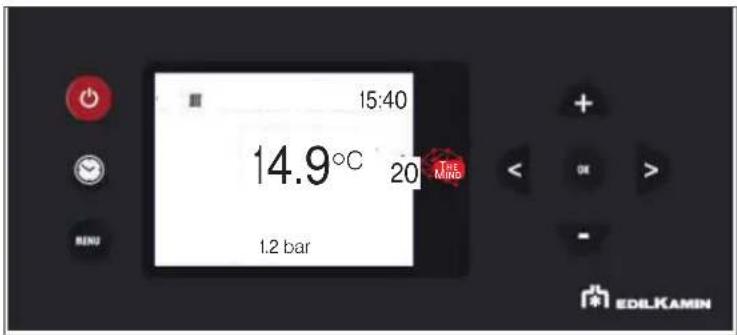
The displays follow the functions at the same time and are described in the following paragraphs:
text_image
15:40 14.9°C 20 THE MIND 1.2 bar EDILKAMIN-BUTTONS
The display has 8 buttons:

ON/OFF: to go from the OFF status to the ON status. In the Menus, to confirm and return to the main screen.

+/-: to increase/decrease the set values or scroll the menu items

M: to access the Menu or to exit the Menu items without saving

OK: to confirm an operation (2 seconds) or to access a menu item

<>: to adjust the ventilation and move through the menus
Energy saving of the display
After 1' of inactivity of the display, the backlight turns off
After 3' of inactivity, the display turns off
To reactivate it, press any button
When first switched on, if the language was not set, the screen on the side for setting the language appears.
Choose the language with the +/- buttons and confirm with OK.
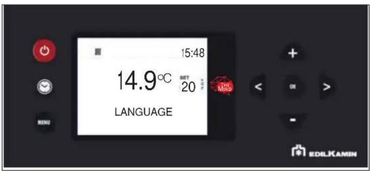
text_image
15:48 14.9°C SET 20 LANGUAGE THE MIND EDELKAMIN
Choose the language with the buttons and select it with button OK
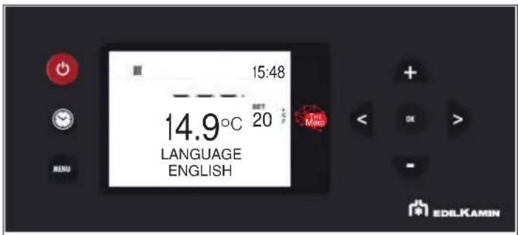
text_image
15:48 14.9°C SET 20 LANGUAGE ENGLISH TEL Mino EDILKAMINFrom the display it is possible to:
- Switch from OFF to ON status, keeping the ON/OFF button pressed for a long time
- Set the room temperature desired, using buttons +/- (see below)

Switching on and off takes a few minutes, during which the flame must appear or go out. Let it happen without intervening. During ignition, the display shows the word "START".
During shutdown, the display shows the word "OFF".
- SIMPLIFIED USE after first start-up
In the default configuration, after having powered up, press the ON/OFF button on the display to "activate" the product and adjust the desired room temperature with buttons +/-. The product will turn on, turn off and adjust the power automatically to ensure the desired temperature.

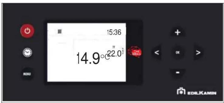
text_image
15:36 14.9°C 22.0 ° THE Mino EDILKAMINPress button

access the Menu screen.
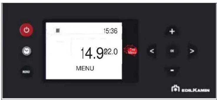
text_image
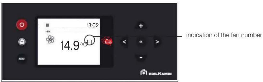
15:36 14.922.0 MENU THE MIND EDILKAMIN- FAN ADJUSTMENT
The setting can be made with the stove turned OFF or ON.
If the backlight is switched off, it can be activated by pressing any button.
Then by pressing button < or >ET flashes and instead of environment Set, the indication of the number of fan in modification (F1) appears.
text_image
18:02 14.9°F1 indication of the fan number EDLKAMINThe fan speed can be increased or decreased with < or > on the following sequence: AUTO -1 -2 -3 -4 -5
The setting is confirmed with button OK.
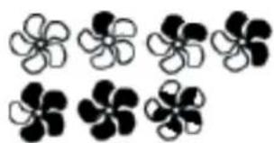
- FAN STATUS DISPLAY
If the product has not heated up, no symbol will appear.
natural_image
Black and white abstract flower-like shapes arranged in two rows (no text or symbols)| FAN OFF: | |
| SPEED 1 | |
| SPEED 2 | |
| SPEED 3 | |
| SPEED 4 | |
| SPEED 5 | |
| AUTOMATIC |
POSSIBLE STATUSES of the product:
- OFF STATUS
The product is “deactivated” and does not produce heat, following manual shutdown with ON/OFF of the radio control or with intervention from an external contact (crono, telephone dialler).
From the OFF screen, the ON screen can be accessed by pressing the ON/OFF button for 3 seconds.
- ON STATUS
Situation in which the product is “active” and can satisfy the heat demands.
- ALARM STATUS
In case of Alarm Block, the display shows the type of alarm. See the paragraph "Tips for possible problems"
- ON/OFF STATUS Stand-By active
Situation in which the product is momentarily turned off because it has no heat demand.

With stand-by active, in the ON status the product switches on only when there is a heat request.
If the product was working, it goes to minimum power and waits for the set time before turning off.
If the product was in the ignition phase, it completes the ignition phase, goes to minimum power and waits for the set time before switching off.
If the product was OFF and is brought to ON, the stove immediately goes into stand-by, without turning it on.

We recommend, at the end of installation and commissioning, to check daily operations and useful documents with the technician.
- MENU
It can be accessed by pressing the MENU button and the first Menu item will appear.
You can scroll the menu items with the < and > buttons, and enter the item with the OK button
The Menu items are as follows
STAND-BY
PELLET LOAD
CRONO
TEMP. CRONO (T1-T2)
DATE-HOUR
LANGUAGE
DISPLAY
others ONLY under the guidance of technician
NOTE
Order and writing may vary slightly depending on the version

We recommend, at the end of installation and commissioning, to check all the daily operations and useful documents with the technician.
The set-point digits contain the progressive number of the menu item, while the status bar includes the description of the item
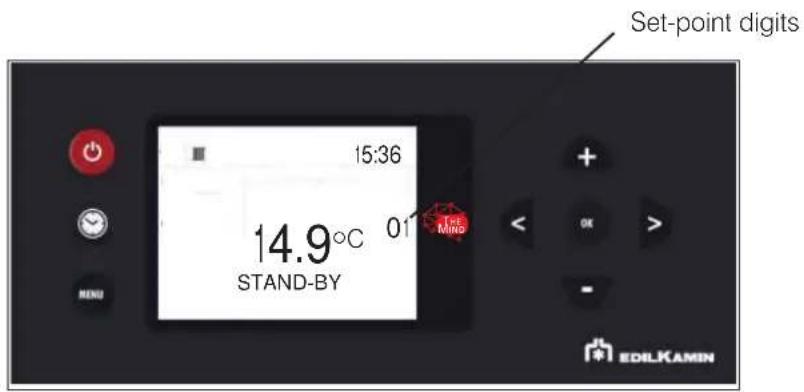
text_image
Set-point digits 15:36 14.9°C 01 STAND-BY MIND EDILKAMINTo exit the menu, press

- STAND-BY
With the Stand-by function active, when the desired temperature is reached, the product switches off and switches on again when the room temperature drops below the desired one.
When the Stand-by function is not active, the product sets itself to minimum power when the temperature set-point is reached.
To access the function from the main menu (as indicated in the Menu paragraph above), press the button
You can scroll the menu items with the < and > buttons, and enter the item with the button
After entering the Stand-by function, the display will show the name of the function on the first line of the status bar and the current value on the second line (OFF if deactivated, ON if active).
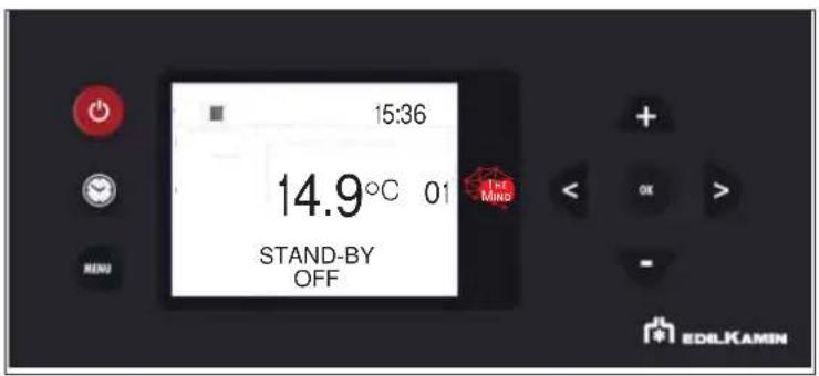
text_image
15:36 14.9°C 01 STAND-BY OFF THE MIND EDILKAMINThe + and - buttons can be used to modify the value from Off (function deactivated) to On (activated) and the OK button can be used to confirm.
Pressing the ON button with the value ON activates the function and the display will propose to choose how many minutes must pass before the device switches off in stand-by mode.
(example 4 minutes)

text_image
15:36 14.9° 01 STAND-BY 4 MIN THE M No EDILKAMINThe + and - buttons can be used to modify the time, and the - button to confirm
Pressing the 🔒 button automatically takes you to the first level.
- PELLET LOADING
Allows for loading the pellets once the screw feeder has emptied completely.
Useful for the technician during the initial start-up.
Available only in the OFF status. Any attempt to activate the function in other statuses will not be allowed.
To access the function from the main menu (as indicated in the Menu paragraph above), press the MENU button
You can scroll the menu items with the < and > buttons, and enter the item with the 📄 on
After entering the Screw Feeder Manual Loading function, the display will show the name of the function on the first line of the status bar and the current value on the second line (OFF if deactivated, ON if active).
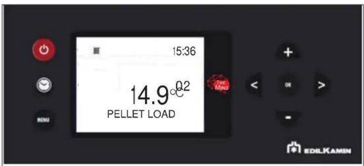
text_image
15:36 14.9°0.2 PELLET LOAD THE MING MENU + OK > - EDILKAMINWith buttons + and - the value can be changed from Off (deactivate) to On (activate) and vice versa and with button + and - can be adjusted.
Pressing the OK button automatically takes you to the first level.
- CRONO SETTING
To access the function from the main menu (as indicated in the Menu paragraph above), press the 📄 button
You can scroll the menu items with the < and > buttons, and enter the item with the = □ on
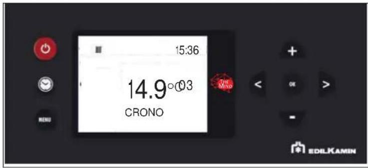
text_image
15:36 14.9°03 CRONO THE MIND EDLKAMIN
day of the week e.g. = MON = Monday
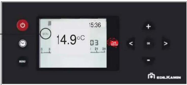
text_image
15:36 14.9°C 03 THE MIND EDILKAMINThe day of the week is selected by scrolling with buttons < and > at the same time the programming of that day is displayed) and confirmed with button OK.
day of the week e.g. = MON = Monday
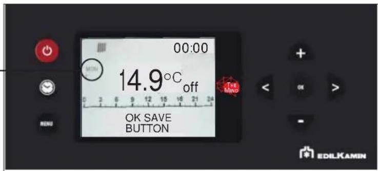
text_image
00:00 MIN 14.9°C off OK SAVE BUTTON THE Mino EDLKAMINThe time at the top right displays the start of the time slot (00:00)
buttons < and > enable to scroll through the time in half an hour steps.
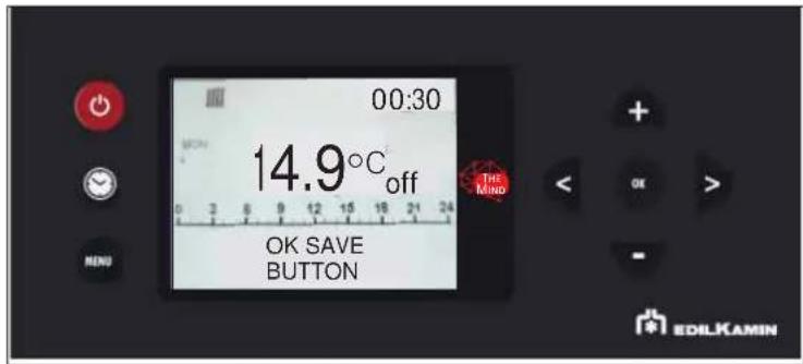
text_image
00:30 14.9°C off OK SAVE BUTTON THE MIND EDILKAMINWith buttons + and ▼ Temperature levels can be changed (OFF - T1 and T2).
After setting the entire day, confirm with the button
The COPY and PASTE function is available.

text_image
15:36 14.9°C 21.0 OK PASTE BUTTON MENU + - OK EDILKAMINBriefly pressing the 📄 button allows you to exit the programming mode, but the programme will not activate.
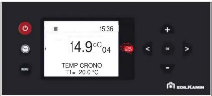
- TEMP. CRONO SETTING TEMPERATURE FOR CRONO T1 - T2
To access the function from the main menu (as indicated in the Menu paragraph above), press the button
You can scroll the menu items with the < and > buttons, and enter the item with the 📄 on
After entering the T1-T2 function, the display will show the name of the function on the first line of the status bar and the current value of T1 on the second line. T1 is the lowest temperature, T2 the highest.
Modify the values with the + and - buttons and confirm with the ☑ on.
text_image
15:36 14.9°C 04 TEMP CRONO T1= 20.0 °C THE MIND EDILKAMINThe button ⚫ switches to the setting of Set T2.
Pressing the OK button automatically takes you to the first level.
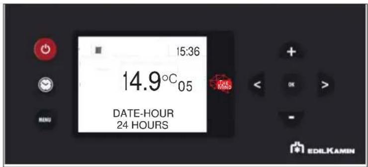
- DATE AND TIME
Can be used to set the current date and time.
To access the function from the main menu (as indicated in the Menu paragraph above), press the 📄 button
You can scroll the menu items with the < and > buttons, and enter the item with the 🔊 on
text_image
15:36 14.9°C 05 DATE-HOUR 24 HOURS EDILKAMINAfter entering the Date-Time function, the display will show the name of the function on the first line of the status bar and the current value of the first setting (12/24 hours) on the second line.
You can switch from 12 to 24 hours using the + and - buttons and confirm with the 📷 on
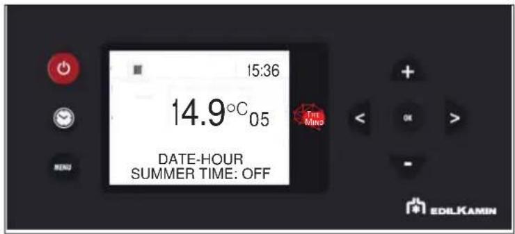
text_image
15:36 14.9°C 05 DATE-HOUR SUMMER TIME: OFF EDILKAMINThen the hours flash, which can be changed with buttons + AND - and they are confirmed with button OK
The minutes will then flash.
NOTE
Depending on the model there may be further options requested on the display with the interactive menu
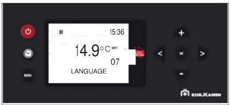
- LANGUAGE SETTING
Selects the language.
To access the function from the main menu (as indicated in the Menu paragraph above), press the MENU button
You can scroll the menu items with the < and > buttons, and enter the item with the
When entering the Language Menu item, the name in the status bar on the first line of the function and on the second the current value is displayed (ITALIAN)
text_image
15:36 14.9°C SET 07 LANGUAGE THE MIND EDILKAMIN

text_image
15:36 14.9°C SET THE MIND LANGUAGE ITALIAN 07 MENU EDILKAMINThe language can be changed with buttons + and " you can exit with button . OK
Pressing the MENU button automatically takes you to the first level.
The following functions must be taken into account only following indications from the technician.
Therefore, we do not report the complete explanation in this document
It can be accessed by pressing the 📄 button and the first Menu item will appear.
You can scroll the menu items with the < and > buttons, and enter the item with the 📄 on
The Menu items are as follows
STAND-BY: described in the user manual
PELLET LOAD: described in the user manual
CRONO: described in the user manual
TEMP. CRONO (T1-T2): described in the user manual
DATA-ORA: described in the user manual
LANGUAGE: described in the user manual
DISPLAY
INFO
SOFTWARE
DATA
ALARMS
PELLET FALL
PELLET SENSOR
TECHNICAL MENU
SET TEMPERATURE
AIRKARE
NOTE
Order and writing may vary slightly depending on the version
FOR THE INSTALLER
To access the function from the main menu (as indicated in the Menu paragraph above), press the MENU button
You can scroll the menu items with the < and > buttons, and enter the item with the 📄 button
Pressing the 📄 button automatically takes you to the first level.
Pressing the MENU button automatically takes you to the first level.
THE INPUT METHOD IS THE SAME FOR ALL THE FUNCTIONS AND WE WILL NOT REPEAT IT IN THE FOLLOWING PAGES WE DESCRIBE BELOW ONLY THE FUNCTIONS NOT DESCRIBED IN THE USER PART
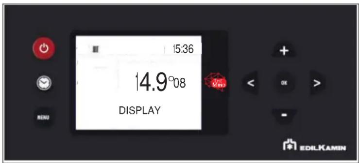
- DISPLAY
Allows for choosing the level of brightness of the display.
text_image
15:36 14.9°08 DISPLAY The Mind EDILKAMIN- DISPLAY
Allows for choosing the level of brightness of the display.
- INFO
These readings should only be done when requested by the technician.
The technician understands the diagnostic meaning of the messages and values, and may ask you to read them to him/her if you experience problems.
To access the function from the main menu (as indicated in the Menu paragraph above), press the MENU button.
You can scroll the menu items with the < and > buttons
Pressing the MENU button automatically takes you to the first level.
- SOFTWARE
These readings should only be done when requested by the technician.
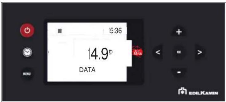
- DATA
These readings should only be done when requested by the technician.
Scroll the information on the product HOURS operation history with buttons < and >
- ALARMS
Readings to be made only under the guidance of a technician. Alarms are sorted from most recent to oldest.
-PELLET FALL ONLY FOR THE TECHNICIAN
-PELLET SENSOR ONLY FOR THE TECHNICIAN
-TECHNICAL MENU ONLY FOR THE TECHNICIAN
-SET TEMPERATURE ONLY FOR THE TECHNICIAN
-AIRKARE ONLY FOR THE TECHNICIAN
The functions must be taken into account only following indications from the technician.
Therefore, we do not report the complete explanation in this document

NOTES
inappropriate changes can cause the product to seize up
The technician will be able to give you indications of any temperatures, parameters to be set according to the system
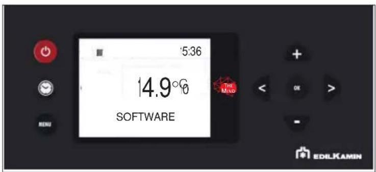
- SOFTWARE
Indicates:
• the firmware version of the electronic board (basic board)
• the firmware version of the control panel
• the database (associated by the Technical Assistance Centres with the products)
To be read only under the guidance of the Technical Assistance Centre
text_image
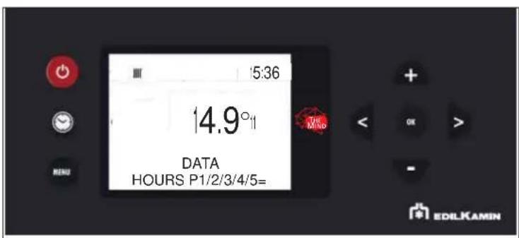
5:36 14.9° SOFTWARE THE MNO EDILKAMIN- DATA
The information on the operation history of the product can be scrolled with buttons indicates:

• IGN. No.: number of ignitions
• WORKING HOURS: total working hours
• HOURS P1/P2/P3/P4/P5: hours worked in the single powers
text_image
5:36 14.9¢ DATA THE MND + - OK > - ENDU EDILKAMIN
text_image
15:36 14.9° DATA HOURS P1/2/3/4/5= EDILKAMIN- INFO
They provide instant situation values
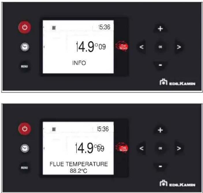
text_image
15:36 14.9°09 INFO THE MIND EDLKAMIN 15:36 14.9°09 FLUE TEMPERATURE 88.2°C EDLKAMINBelow is a description of the items
Flue temperature indicates the value of the temperature read inside the product. To be read only under the guidance of the Technical Assistance Centre
Auger motor: indicates the speed set and read. Useful for understanding any anomaly in the motor that loads the pellets. To be read only under the guidance of the Technical Assistance Centre
Extractor: indicates the speed set and read. Useful for understanding any anomaly in the engine that creates depression in the combustion chamber. To be read only under the guidance of the Technical Assistance Centre
Leonardo: indicates the target value set and read. To be read only under the guidance of the Technical Assistance Centre
Fan: indicates the output voltage. To be read only under the guidance of the Technical Assistance Centre
Ignition plug (spark plug): indicates whether the ignition component is on or off. Useful in the ignition phase to understand functionality.
Home automation contact: indicates whether ON or OFF. Useful for understar functionality.
Boiler temperature: indicates the value of the water temperature read inside the product. It also appears on the first level display only if "No Input" is set in the Input Ambience parameter. ATTENTION that the room temperature will no longer appear. IN CASE, TO BE CLARIFIED TO THE END CLIENT.
To be read only under the guidance of the Technical Assistance Centre
PWM pump : indicates the output value of the primary circuit pump (of the kit if optional) To be read only under the guidance of the Technical Assistance Centre.
3-way valve for heating : indicates the functionality of the valve.
Relaunch pump : indicates whether the pump is ON or OFF.
AUX relay : indicates if OPEN
Radio signal: indicates the signal strength in milliwatt decibels. Admissible values from 0 to -95dB
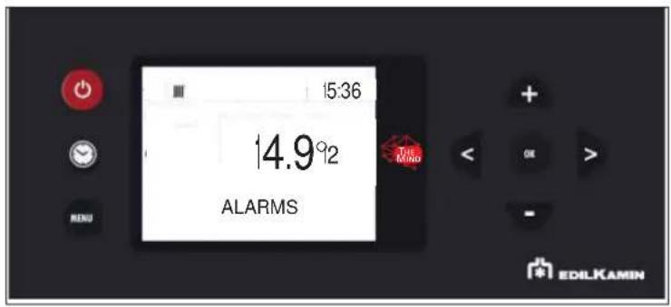
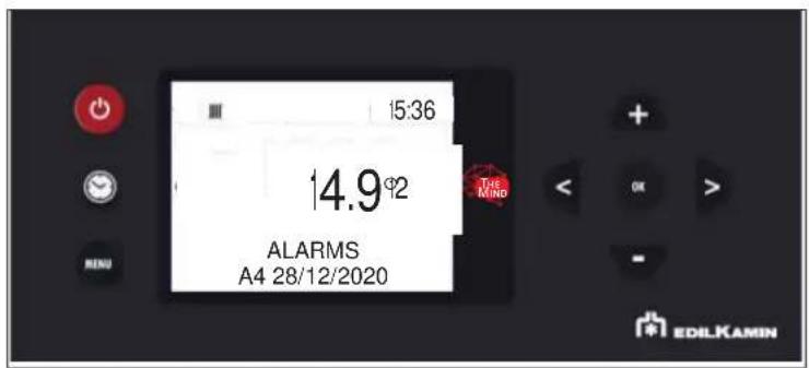
- ALARMS
These readings should only be done when requested by the technician.
The alarms are arranged from the most recent to the oldest.
text_image
15:36 14.9°2 ALARMS THE MIND EDILKAMIN
text_image
15:36 14.9°2 ALARMS A4 28/12/2020 THE MIND EDILKAMINThe meaning of the abbreviations is given in the user manual
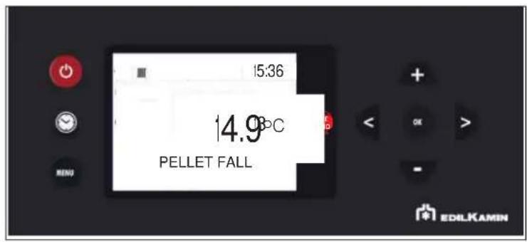
- PELLET FALL
Allows to set the gearmotor in continuous cycle or in steps. To be carried out only under the guidance of a technician.
text_image
15:36 14.9°C PELLET FALL EDILKAMIN
text_image
15:36 14.9°2 PELLET FALL CONTINUES THE MIND EDILKAMIN- PELLET SENSOR
Allows to set the pellet level sensor ON or OFF.
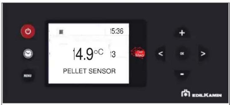
text_image
15:36 14.9°C 13 PELLET SENSOR THE MINO EDILKAMININ ORDER OF SCROLLING IT IS FOUND AFTER THE TECHNICAL MENU
- "SET TEMPERATURE" o the displaySetting the water temperatures)
Allows the setting of the boiler temperature and possibly the storage temperature. If the external probe is activated, it allows the setting of the climatic curve instead of the boiler temperature.
ADJ T AMB 1 is also adjusted (i.e. the correction of the ambient probe)
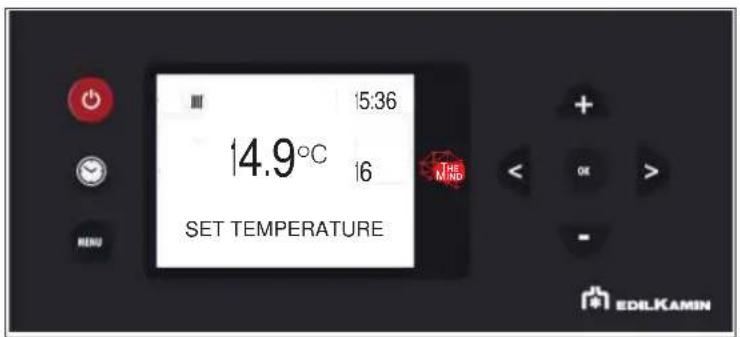
text_image
15:36 14.9°C 16 SET TEMPERATURE EDILKAMINBOILER SET example
the product water temperature can be set (BOILER on display)
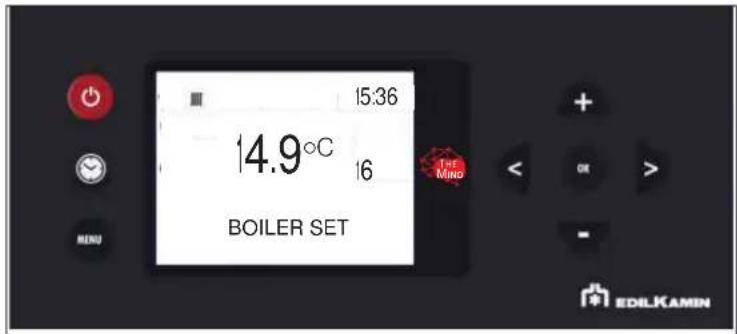
text_image
15:36 14.9°C 16 BOILER SET 1st Mino EDILKAMINDepending on the configurations, the temperatures are displayed.
Example:
INSTANT VALUE
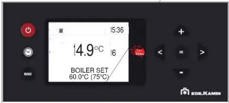
text_image
15:36 14.9°C 16 BOILER SET 60.0°C (75°C) Tie Ming MENU EDILKAMIN- TECHNICIAN MENU (for TECHNICIANS ONLY)
Accessible only by a technician in possession of the correct password (1111) Once the password has been
entered, it must be confirmed with a button

- Flame type
- Pellet type
- Configuration
- Parameters

NOTES
inappropriate changes can cause the product to seize up
- FLAME TYPE (only for the TECHNICIAN)
In correct installation conditions, with the Service Centre parameters appropriately adjusted, with quality pellets, the intensity of the flame is adjusted:
STANDARD
ECO
PLUS
You can enter the Flame Type setting using the button

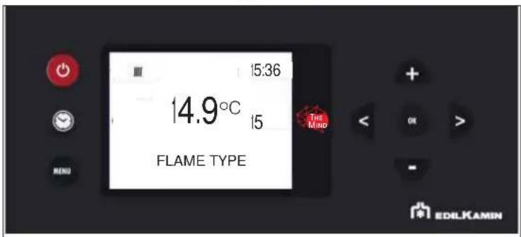
text_image
15:36 14.9°C 15 THE MIND FLAME TYPE MENU EDILKAMINand with buttons + and correction value can be changed.
Pressing the 📄 button automatically takes you to the first level.
- PELLET TYPE
In correct installation conditions, with the Service Centre parameters appropriately adjusted, with quality pellets, the pellet load is adjusted
MEDIUM
HIGH
LOW
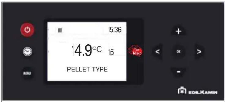
text_image
15:36 14.9°C 15 PELLET TYPE THE MIND MENU + OK > - EDILKAMINEnter the Pellet Type (%) setting with button OK
and modify the value with buttons + and -
Pressing the 📂 button automatically takes you to the first level.
- CONFIGURATION
Scroll through the Technician Menu items with buttons < and > the "CONFIGURATION" item
It is possible to enter the "CONFIGURATION" setting with button OK
and modify the value with buttons + and -
Pressing the ⬤ button automatically takes you to the first level.
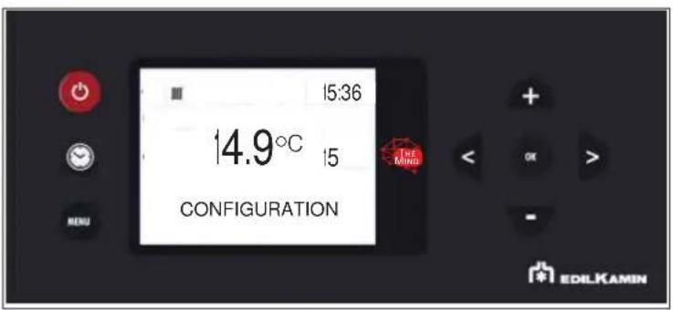
text_image
15:36 14.9°C 15 CONFIGURATION EDILKAMINThe installer chooses one of the 4 configurations:
0 DIRECT HEATING (possibly with combined boiler)
1 HEATING WITH PUFFER (inertial storage)
2 HEATING WITH SANITARY STORAGE (possibly with combined boiler)
3 HEATING WITH PUFFER (inertial storage) AND BOILER (storage of domestic hot water)
TO BETTER UNDERSTAND THE ABOVE FOLLOWING PAGES ON TERMINAL BLOCK AND SYSTEMS
To manage the various types of systems, connect the probes to the terminal board, as needed.
TERMINAL BOARD MAIN OUTLINE
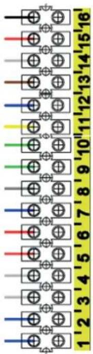
text_image
1'2'3'4'5'6'7'8'9'10'11'12'13'14'15'16'15-16 = CYLINDER PROBE (Optional NTC 10K) or THERMOSTAT (Optional)
13-14 =DOMOTIC CONTACT (Input)
11-12 =ROOM PROBE (Supplied) or ROOM THERMOSTAT (Optional)
9-10 = BUFFER PROBE (Optional NTC 10K) - BUFFER THERMOSTAT (Optional)
7-8=BUFFER-CYLINDER DOUBLE PROBE (Optional NTC 10K probe)
4-5-6 = AUX CONTACT - Output, aux boiler room thermostat or 3-way valve (COM = Common - NC = Normally Closed - NO = Normally Open).
1-2-3 = SECONDARY PUMP POWER SUPPLY (Earth / Neutral / Phase)
HOME AUTOMATION CONTACT 13-14
For all types of systems:
HEATING - KETTLE - PUFFER - PUFF / TUB
it is possible to connect a remote control with clean contact (closed on request, open not on request).
This contact has the same function as the on / off button on the display.
Following the closure of the contact, however, the thermo stove will follow its objective defined by the selected system and the functions associated with it, as happens when the power button on the display is pressed.
There are 4 pre-set configurations as shown below.
DAILY MAINTENANCE
These jobs should be done with the product off, cold and preferably disconnected from the mains.
A suitable vacuum cleaner is required.
Disconnect the product f power supply.
Failure to service the product properly will prevent it from working properly.
Any problems due to failure in servicing the stove will void the warranty.

tMake sure that the grate is properly placed in its
housing after maintenance operations, if not, the stove may have ignition problems
Using the stove without cleaning the grate can cause the gas in combustion chamber to ignite and detonate.

Once it is refitted, make sure that the ash tray is properly placed in its housing, to avoid glass breakage when closing.
DAILY MAINTENANCE
- "Rub the cleaning rod under the pellet loading cover with the removable handle supplied
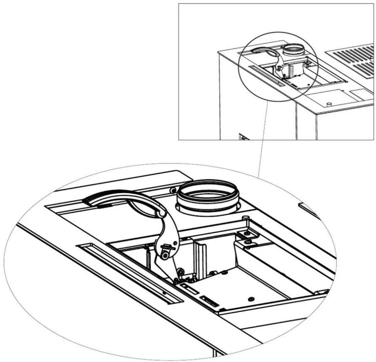
natural_image
Technical line drawing of a mechanical assembly with an inset close-up showing internal components (no text or symbols)- Open the combustion chamber door (P) using the removable handle.
- Empty the ash tray (B) and grate (C) into a non-flammable container (the ashes may still contain embers and/or hot parts) or vacuum if cold. Vacuum the interior of the combustion chamber, the bed, and the compartment around the burning pot into which the ash falls.
- Scrape the burning pot with the scraper and clean out any obstructed holes.
- If necessary, clean the glass when cold using dedicated product (e.g. Glasskamin), which your dealer should have.
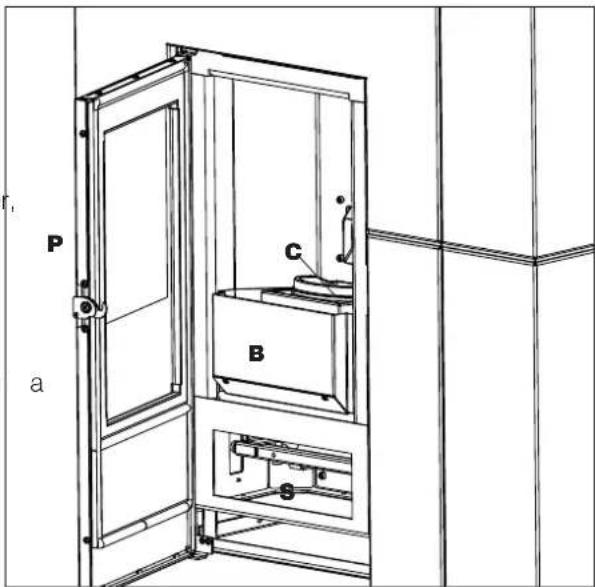
text_image
P a C B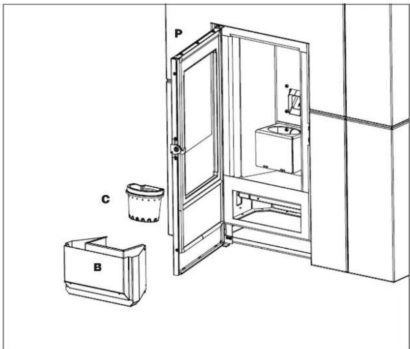
text_image
Technical diagram of an elevator system with labeled components P, C, and BWEEKLY MAINTENANCE
With the product switched off and cold, vacuum the inspection window beneath the combustion chamber (*)
To access it:
- open the door of the lower front panel using the removable handle
- remove the deflector (D) which merely rests on it
After cleaning the element, put the deflector back on and close the door of the lower front panel
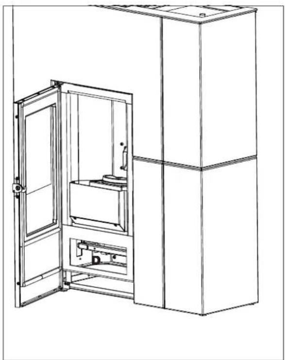
natural_image
Line drawing of a cabinet with an open door opening, showing internal components and structural details (no text or symbols)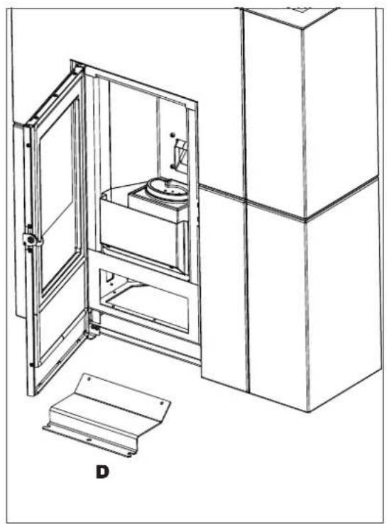
natural_image
Technical line drawing of a mechanical device with open door, internal enclosure, and base plate (no text or symbols)
Make sure you have correctly repositioned the deflector after cleaning: it should lie horizontally between the two screws
SEASONAL MAINTENANCE
(to be carried out by the technical assistance centre)
This consists of cleaning the stove inside and out.
If the product is used intensively, recommend cleaning the smoke duct and passage every 3 months.
You should clean the chimney system at least once a year (check local regulations for details).
If you fail to regularly clean and inspect the there is an increased risk of the chimney pot catching fire.
We recommend against using compressed air to clean the combustion air inlet
Technical interventions
Please contact your local retailer and/or an Edilkamin technician if spare parts are needed.
Technical interventions must be carried out by a licensed and qualified Technical Assistance centre/Edilkamin retailer ONLY.
Licensed and qualified Technical Assistance Centre/Edilkamin retailers company names are available of the Edilkamin website www.edilkamin.com ONLY.
Use of non-original spare parts may cause produce hazards, exonerating Edilkamin from any liability and damage caused, interrupting the warranty as a result
systampering.
SUMMER SHUTDOWN
During the period of disuse, keep the stoves doors, hatches and lids closed.
We recommend emptying out the pellet tank. Place dehumidifying salts in the combustion chamber.
Consider to remove air intake if you are in zone where it can damage
SPARE PARTS
For any spare parts, contact your dealer or technician.
Licensed and qualified Technical Assistance Centre/Edilkamin retailers company names are available on the Edilkamin website www.edilkamin.com ONLY.
Use of non-original spare parts may cause product hazards, exonerating Edilkamin from any liability and damage caused, interrupting the warranty as a result of tampering.
Do not make any unauthorised modifications.
DISPOSAL
At the end of its service life, dispose of the product as required by regulations.

natural_image
Symbol of a trash bin crossed out by two diagonal lines (no text or labels)
In accordance with art. 26 of Legislative Decree no. 49 of 14th March 2014, “Implementation of Directive 2012/19/UE on the disposal of electrical and electronic devices (RAEE)”.
The crossed-out dustbin symbol displayed on equipment or its packaging indicates that the product at the end of its life must be collected separately from other waste.
At the end of its useful life, the user should therefore deliver the product to a suitable local sorted collection centre for electrical and electronic devices.
Sorted collection for recycling, treatment and environmentally compatible scrapping contributes to the prevention of negative effects on the environment and health, and promotes the re-use and recycling of the materials of which the equipment is made.
If problems occur, the product shuts itself off automatically.
The display will show the reason (see below).
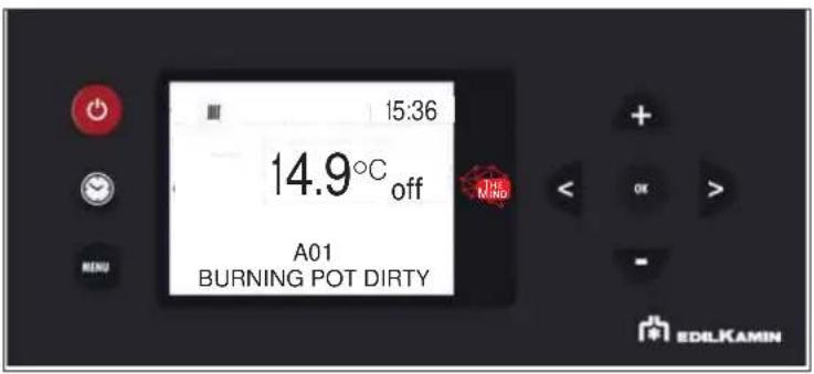
text_image
15:36 14.9°C off A01 BURNING POT DIRTY EDILKAMIN| MESSAGE PROBLEM SOLUTION | ||
| A01 burning pot dirty | displays when the combustion air intake is below the set level | Check that the combustion chamber door is closed. Check the regular maintenance of the stove. Check that smoke discharge and combustion air ducts are clean. |
| A02 | displays when the logic board is not detecting the right smoke fan speed | Contact the technician |
| A03 | displays when the thermocouple detects a smoke temperature lower than the set value interprets this as the absence of flame | Check that there are pellets in the tank. Check that the water temperature has not increased and due to the closure of a valve (call a technician). Contact the technician |
| A04 | displays when ignition times out unsuccessfully | There are two possibilities: NO flame:Check that the burning pot is seated properly and clean. Check that there are pellets in the tank and burning pot. Try switching it on with a solid ecological igniter (contact the technician beforehand and follow the instructions of the igniter supplier very carefully). The operation must be regarded purely as a trial under the technician's guidance |
| A05 | Shutdown due to air flow sensor breakage | rate. Contact the technician |
| A06 | displays when the logic board determines that the smoke temperature probe is broken or disconnected | Contact the technician |
| A07 | Shutdown due to exceeding maximum smoke temperature. | Check the type of pellet (contact the techn doubt)contact the technician |
| A08 | Switching OFF due to excessive overheating of the product | see HO7 |
| A09 | Shutdown due to gearmotor breakage or seizure | Contact the technician |
| A10 | Switching OFF due to circuit board overheating. | Contact the technician |
| A11 | Switching OFF due to the intervention of the safety pressure switch. | Ensure the stove and flue are cleanContact the technician |
| A12 | Room temperature probe failure. | Contact the technician |
| A13 | Shutdown due to breakage of the reading water temperature probe of the boiler stove. | Contact the technician |
| A14 | Shutdown due to breakage of the water temperature probe in the boiler | Contact the technician |
| A15 | Shutdown due to exceeding maximum water temperature in the boiler stove | Contact the technician |
| A16 | Shutdown due to breakage of the pressure switch for reading the water pressure of the boiler stove | Contact the technician |
| A17 | Shutdown due to breakage of the external probe | Contact the technician |
| A18 | Shutdown due to breakage of the water temperature probe in the inertial storage tank | Contact the technician |
| A20 | Shutdown due to gearmotor breakage or seizure | Contact the technician |
WATER OVERHEATING (SHUTDOWN WITHOUT ALARM)
If the water in the product reaches a temperature of 85^ C, the product shuts down without switching to alarm mode.
The text STBY appears on the display next to the room temperature.
The product is working, but it must be serviced by an authorised Edilkamin technician.
MAINTENANCE (SIGNAL THAT DOES NOT CAUSE SHUTDOWN)
A spanner symbol will appear on the display after 2,000 hours of operation
The product is working, but it must be serviced by an authorised Edilkamin technician.
text_image
III 15:36 14.9°C off Mino EDILKAMINSeasonal maintenance should be performed by a qualified technician in accordance with the national and local regulations.
Licensed and qualified Technical Assistance Centre/Edilkamin retailers company names are available on the Edilkamin website www.edilkamin.com ONLY.

text_image
Barcode image with black and white vertical bars, no visible text or symbols beyond the pattern
EDILKAMIN
TECNOLOGIA DEL FUOCO
www.edilkamin.com