MAGNA1 - Pompe à eau Grundfos - Notice d'utilisation et mode d'emploi gratuit
Retrouvez gratuitement la notice de l'appareil MAGNA1 Grundfos au format PDF.

| Type de produit | Circulateur de chauffage |
| Marque | Grundfos |
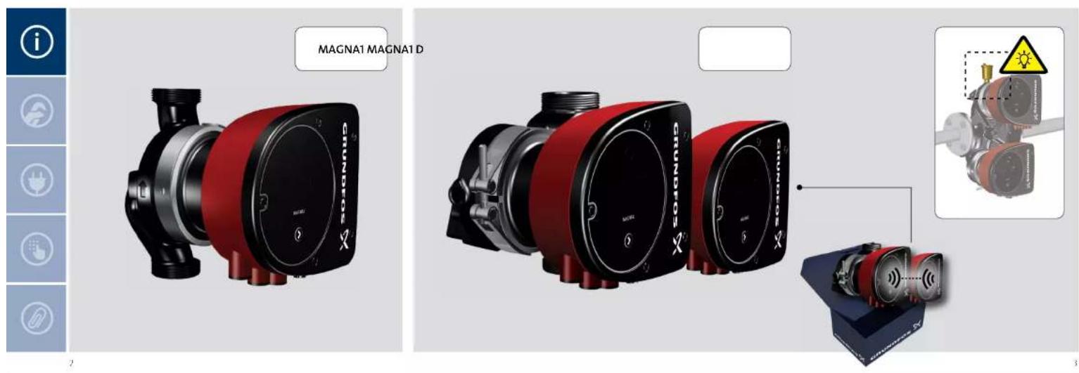
| Modèle | MAGNA1 / MAGNA1 D |
| Plage de température du fluide | -10 °C à +110 °C |
| Pression de service max | PN 6 (6 bar), PN 10 (10 bar), PN 16 (16 bar) selon version |
| Température ambiante | 0 °C à +40 °C |
| Humidité relative max | 95 % RH |
| Indice de protection | IPX4D |
| Niveau sonore | < 39 dB(A) |
| Entrée de commande | Entrée démarrage/arrêt (Start/stop) |
| Sortie relais | Relais de défaut (Fault relay) |
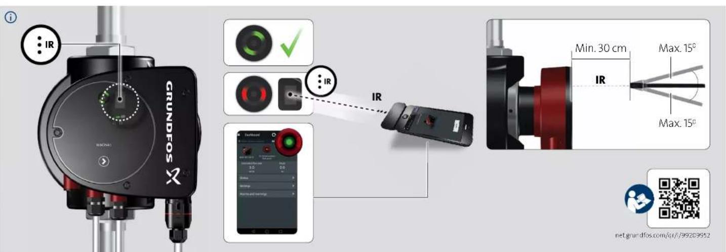
| Télécommande | Infrarouge (IR), angle max 15°, distance min 30 cm |
| Raccordement électrique | Section fil 0,5-1,5 mm², diamètre câble 5,5-10 mm |
| Hauteur de raccordement | 7 mm, 12 mm, 17 mm |
| Cycles de puissance | Max 4 démarrages par 60 minutes |
| Fonctions principales | Circulation d'eau, régulation électronique, commande IR |
| Entretien et nettoyage | Nettoyer l'extérieur avec un chiffon humide ; vérifier périodiquement les connexions |
| Sécurité | Protection IPX4D, limitation des redémarrages |
| Pièces détachées et réparabilité | Consulter le manuel ou le site Grundfos pour les pièces d'origine |
| Informations générales | Garantie 2 ans, fabrication au Danemark |
FOIRE AUX QUESTIONS - MAGNA1 Grundfos
Questions des utilisateurs sur MAGNA1 Grundfos
0 question sur cet appareil. Repondez a celles que vous connaissez ou posez la votre.
Poser une nouvelle question sur cet appareil
Téléchargez la notice de votre Pompe à eau au format PDF gratuitement ! Retrouvez votre notice MAGNA1 - Grundfos et reprennez votre appareil électronique en main. Sur cette page sont publiés tous les documents nécessaires à l'utilisation de votre appareil MAGNA1 de la marque Grundfos.
MODE D'EMPLOI MAGNA1 Grundfos
GRUNDFOS INSTRUCTIONS
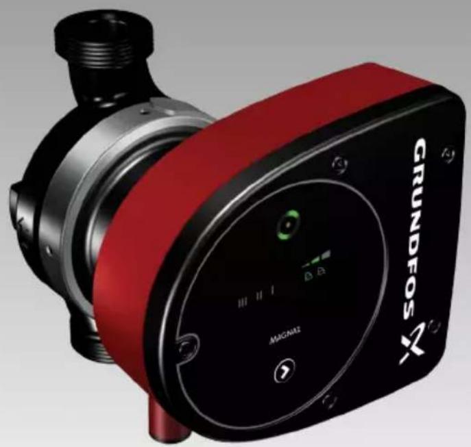
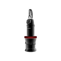
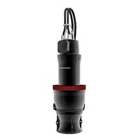
natural_image
Close-up of a red and black industrial pump unit with 'GRUNDFOS' branding and control panel (no readable text beyond branding)MAGNA1
VALID FROM MODEL C
Further product documentation


net.grundfos.com/qr/i/99209952
be think innovate
GRUNDFOS

text_image
MAGNA1 MAGNA1 D MIGNA1 MIGNA1 D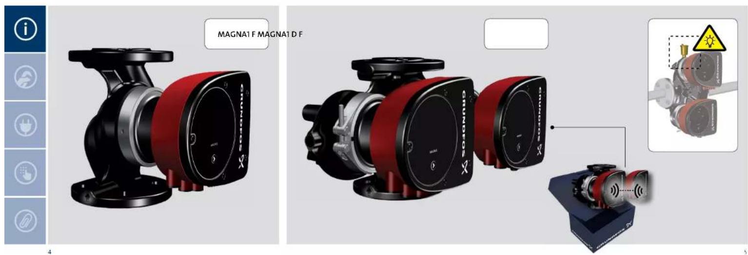
text_image
MAGNA1 F MAGNA1 D F 4 5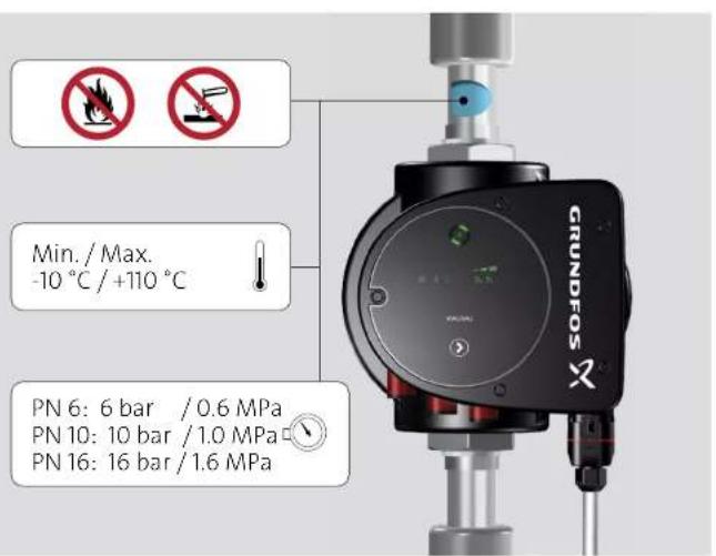
text_image
GRUNDFOS Min. / Max. -10 °C / +110 °C PN 6: 6 bar / 0.6 MPa PN 10: 10 bar / 1.0 MPa PN 16: 16 bar / 1.6 MPa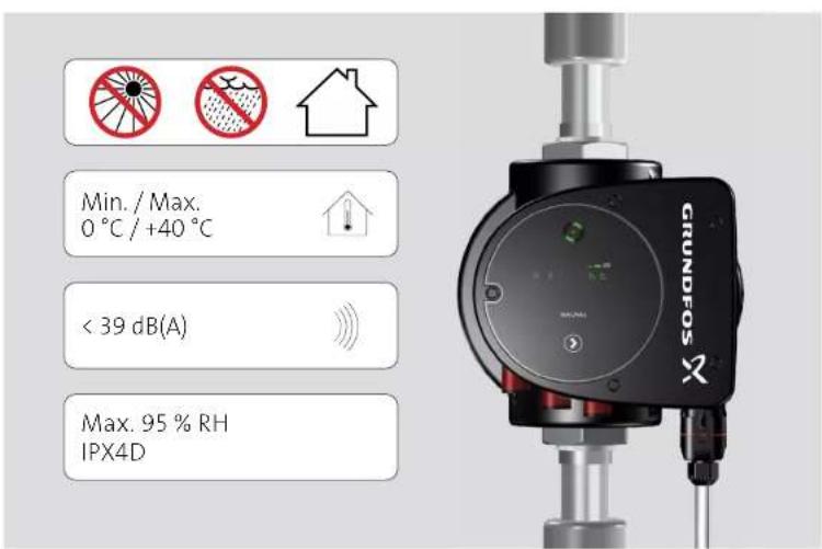
text_image
Min. / Max. 0 °C / +40 °C < 39 dB(A) Max. 95 % RH IPX4D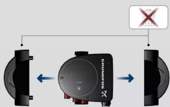
text_image
GRUNDOS X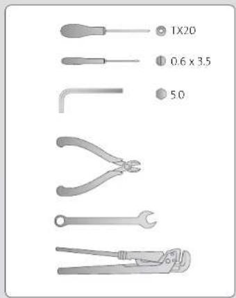
text_image
1X20 0.6 x 3.5 50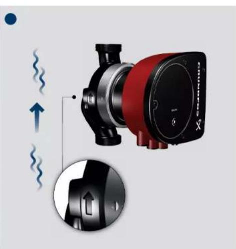
natural_image
Diagram of a red and black pump unit with directional arrows indicating flow or movement (no text or symbols)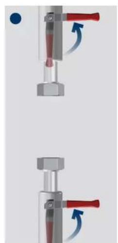
natural_image
Two mechanical assembly diagrams showing a valve mechanism with red and blue arrows indicating motion (no text or symbols)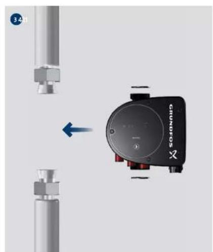
natural_image
Close-up of a digital camera module with a blue arrow indicating left motion, no visible text or symbols on the device itself.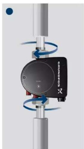
natural_image
Mechanical device with rotating blue arrows and a black circular component labeled 'KONONIO' (no readable text or symbols beyond branding)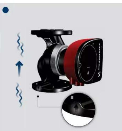
natural_image
Illustration of a red and black industrial pump with directional arrows indicating flow or vibration (no text or symbols)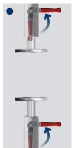
natural_image
Mechanical assembly diagram showing two sequential steps with red and blue components, no text or symbols present.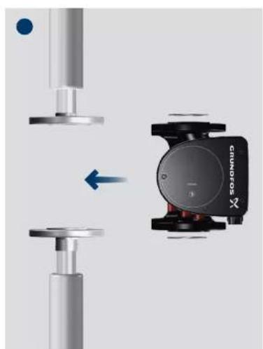
natural_image
Mechanical assembly diagram showing a cylindrical component with a sensor mounted on a base, connected to a vertical shaft (no text or symbols visible)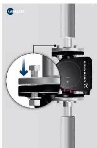
natural_image
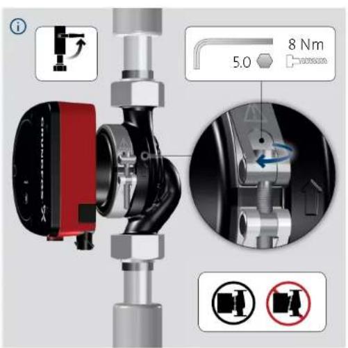
Mechanical assembly diagram showing a bolted joint with a highlighted component and a magnified inset (no readable text or symbols)
text_image
Vertical column of five gray icons with white text, including 'i', a blue square with a globe and plug symbol, and three other icons below.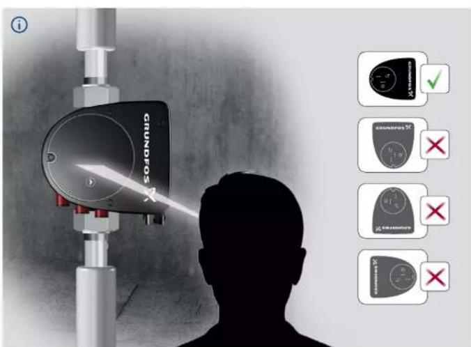
text_image
CINNOS ✓ ✗ ✗ ✗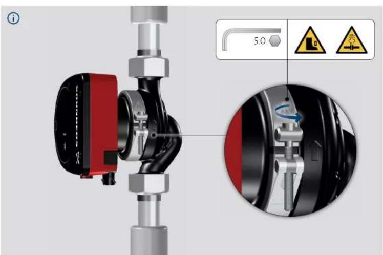
text_image
Technical diagram of a mechanical valve assembly with labeled components and safety warning icons7415

text_image
Vertical sequence of five gray icons with white labels: info, upload, plug, hand, and paperclip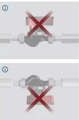
text_image
Diagram showing two identical mechanical or electrical component states with red X marks indicating failure or prohibition.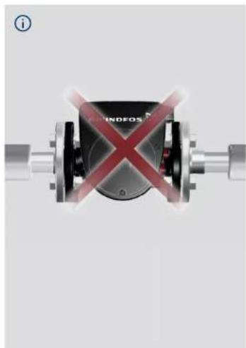
text_image
INDFOS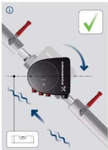
text_image
Diagram illustrating a mechanical or electrical component with labeled parts and directional arrows, including a checkmark and schematic symbols.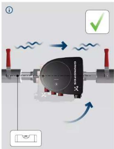
text_image
i SOA0000 1.5 1.5 ✓76.17

text_image
Vertical sequence of five gray icons with white text labels: i, a blue square with a document icon, a plug, a grid interface, and a paperclip.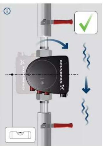
text_image
i GRUNDOS GRUNDOS x x x x x x x x x x x x x x x x x x x x x x x x x x x x x x x x x x x x x x x x x x x x x x x x x x y y y y y y y y y y y y y y y y y y y y y y y y y y y y y y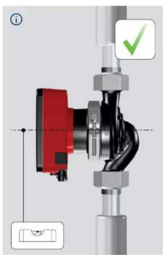
text_image
Technical diagram of a mechanical valve assembly with labeled components and checkmark indicator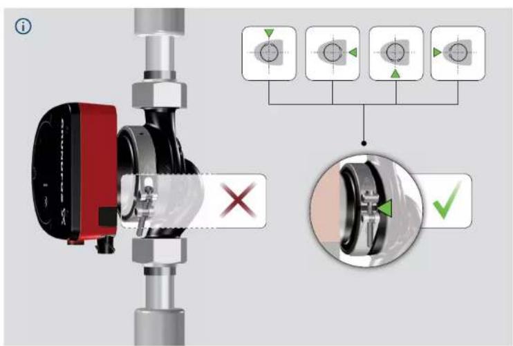
text_image
Technical diagram showing mechanical assembly with labeled components and inspection indicators7819
text_image
i 5.0 8 Nm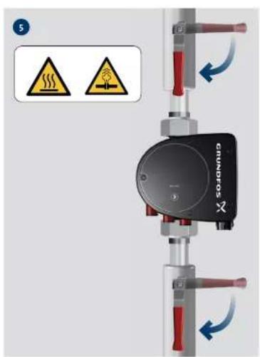
text_image
5 GRUNDOS
natural_image
Mechanical device with two circular components and blue directional arrows indicating rotation or movement (no text or symbols)
natural_image
Mechanical assembly diagram showing a motor or gear assembly with directional arrows and a warning symbol (no text labels)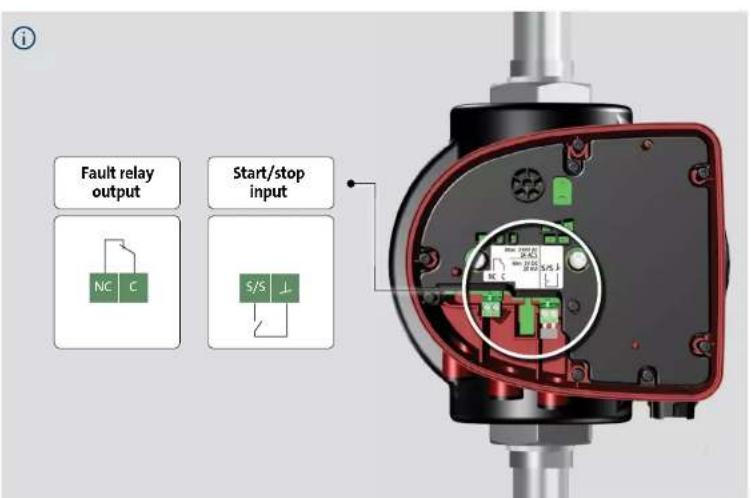
text_image
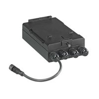
Fault relay output Start/stop input NC C S/S ⊥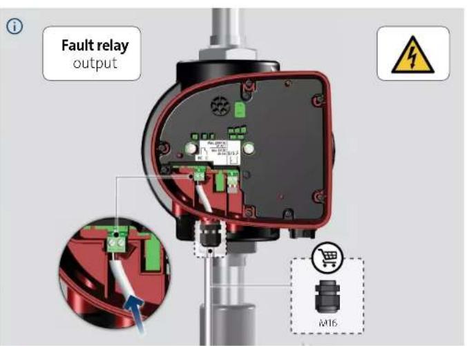
text_image
Fault relay output M16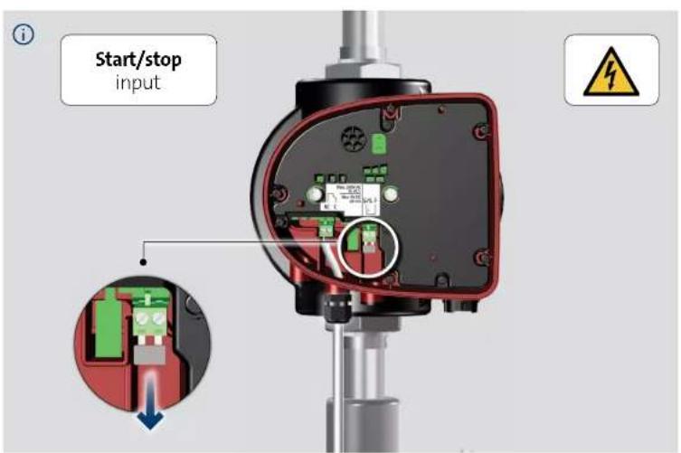
text_image
Start/stop input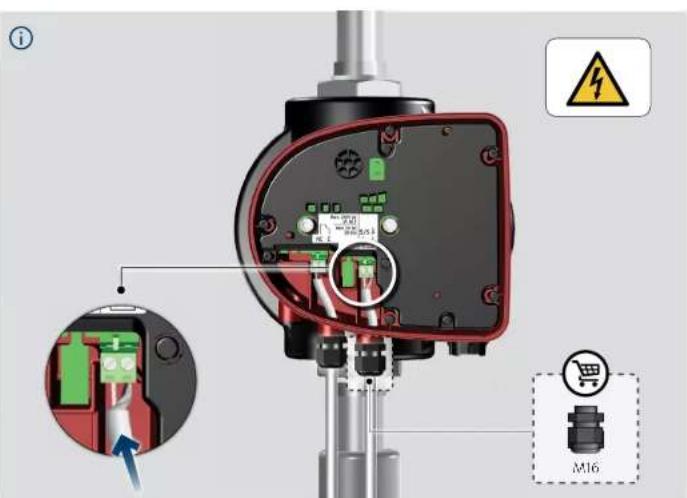
text_image
Technical diagram of an industrial sensor or control device with labeled components and warning symbol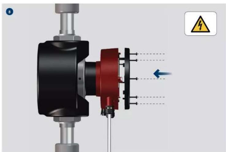
natural_image
Mechanical assembly diagram showing a motor or actuator with red and black components, no visible text or symbols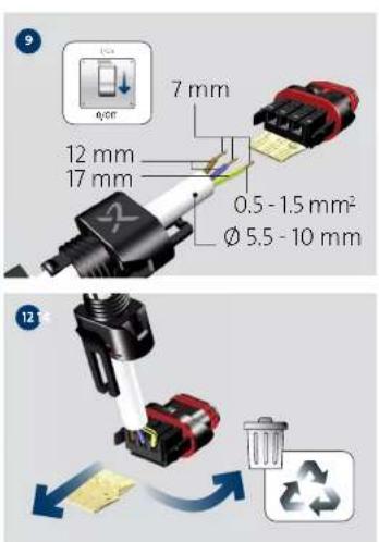
text_image
7 mm 12 mm 17 mm 0.5 - 1.5 mm² Ø 5.5 - 10 mm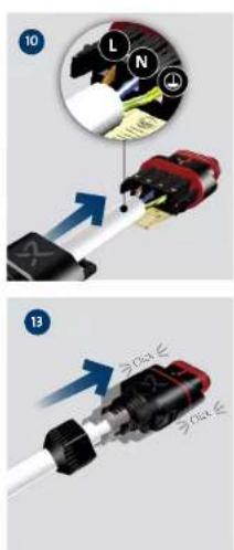
text_image
Diagram showing two steps of a connector assembly with labeled parts and directional arrows indicating movement.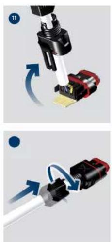
natural_image
Two-step diagram showing a mechanical assembly with arrows indicating motion, no text or symbols present.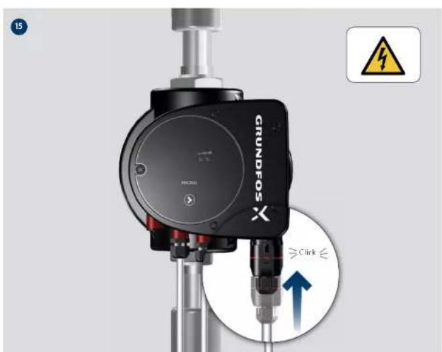
text_image
GRUNDFOS X ≥Click ≤
text_image
16 GRUNDFOS 1/On 0/Off GRUNDFOS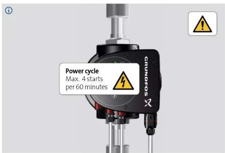
text_image
Power cycle Max. 4 starts per 60 minutes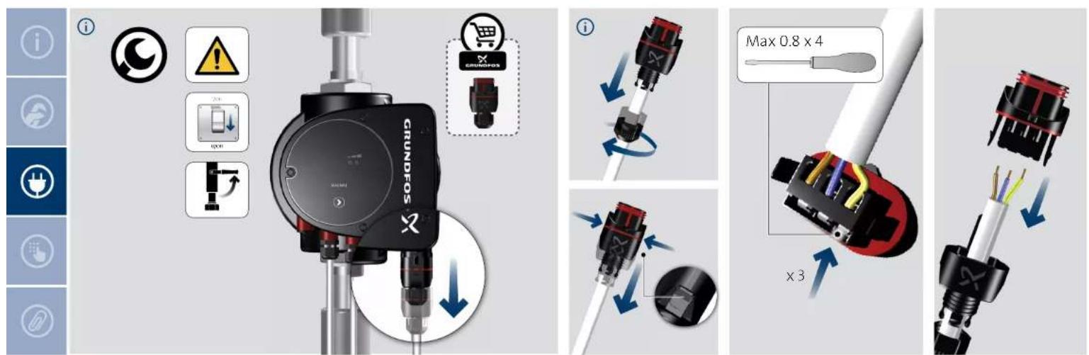
text_image
i IR GRUNDFOS X MIN. 30 cm Max. 15° IR IR Max. 15° min. 30 cm IR net.grundfos.com/qf/799209952i
1x
2X
1x
4X
5×
6X
/×

8X
i


net.grundfos.com/qr//99209952
i
text_image
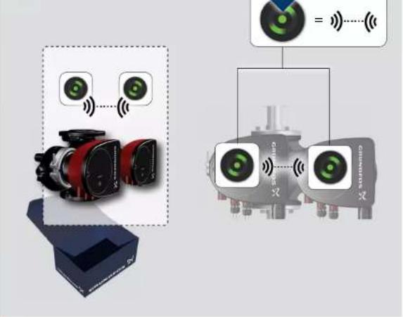
Diagram illustrating wireless signal transmission between two cameras and a sensor, with labeled components and signal icons.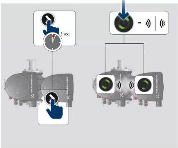
text_image
5 sec. = <|i

text_image
net.grundfos.com/01/9920395218 19
be think innovate
Installation date: ____
Installer:
99334333 07.2020
ECM: 1290169
GRUNDFOS Holding A/S
Poul Due Jensens Vej 7
DK-8850 Bjerringbro
Tel: +45 87 50 14 00
www.grundfos.com
Trademarks displayed in this material, including but not limited to Grundfos, the Grundfos logo and "be think innovate" are registered trademarks owned by The Grundfos Group. All rights reserved.
© 2020 Grunofos Holding A/S, all rights reserved.
GRUNDFOS