MODE D'EMPLOI MX-J30 JVC
JVC
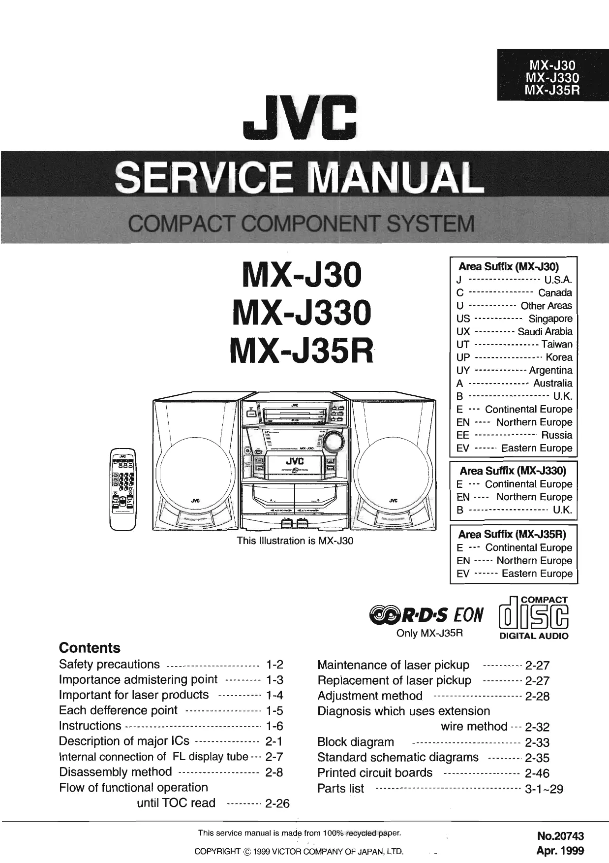
SERVICE MANUAL
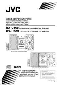
COMPACT COMPONENT SYSTEM
MX-J30
MX-J330
MX-J35R


This Illustration is MX-J30
Area Suffix (MX-J30)
J U.S.A.
C Canada
U Other Areas
US Singapore
UX - Saudi Arabia
UT Taiwan
UP Korea
UY Argentina
A Australia
B U.K.
E - - Continental Europe
EN --- Northern Europe
EE Russia
EV -Eastern Europe
Area Suffix (MX-J330)
E - Continental Europe
EN - Northern Europe
B U.K.
Area Suffix (MX-J35R)
E… Continental Europe
EN - Northern Europe
EV Eastern Europe

R·D·S EON
Only MX-J35R

DIGITAL AUDIO
Contents
Safety precautions 1-2
Importance admistering point 1-3
Important for laser products 1-4
Each defference point 1-5
Instructions 1-6
Description of major ICs 2-1
Internal connection of FL display tube 2-7
Disassembly method 2-8
Flow of functional operation until TOC read 2-26
Maintenance of laser pickup 2-27
Replacement of laser pickup 2-27
Adjustment method 2-28
Diagnosis which uses extension
wire method -2-32
Block diagram 2-33
Standard schematic diagrams 2-35
Printed circuit boards 2-46
Parts list 3-1~29
Safety Precautions
- This design of this product contains special hardware and many circuits and components specially for safety purposes. For continued protection, no changes should be made to the original design unless authorized in writing by the manufacturer. Replacement parts must be identical to those used in the original circuits. Services should be performed by qualified personnel only.
- Alterations of the design or circuitry of the product should not be made. Any design alterations of the product should not be made. Any design alterations or additions will void the manufacturer's warranty and will further relieve the manufacture of responsibility for personal injury or property damage resulting therefrom.
- Many electrical and mechanical parts in the products have special safety-related characteristics. These characteristics are often not evident from visual inspection nor can the protection afforded by them necessarily be obtained by using replacement components rated for higher voltage, wattage, etc. Replacement parts which have these special safety characteristics are identified in the Parts List of Service Manual. Electrical components having such features are identified by shading on the schematics and by ()_A on the Parts List in the Service Manual. The use of a substitute replacement which does not have the same safety characteristics as the recommended replacement parts shown in the Parts List of Service Manual may create shock, fire, or other hazards.
- The leads in the products are routed and dressed with ties, clamps, tubings, barriers and the like to be separated from live parts, high temperature parts, moving parts and/or sharp edges for the prevention of electric shock and fire hazard. When service is required, the original lead routing and dress should be observed, and it should be confirmed that they have been returned to normal, after re-assembling.
- Leakage current check (Electrical shock hazard testing)
After re-assembling the product, always perform an isolation check on the exposed metal parts of the product (antenna terminals, knobs, metal cabinet, screw heads, headphone jack, control shafts, etc.) to be sure the product is safe to operate without danger of electrical shock. Do not use a line isolation transformer during this check.
- Plug the AC line cord directly into the AC outlet. Using a "Leakage Current Tester", measure the leakage current from each exposed metal parts of the cabinet, particularly any exposed metal part having a return path to the chassis, to a known good earth ground. Any leakage current must not exceed 0.5mA AC (r.m.s.)
Alternate check method
Plug the AC line cord directly into the AC outlet. Use an AC voltmeter having, 1,000 ohms per volt or more sensitivity in the following manner. Connect a 1,500 10W resistor paralleled by
a 0.15 F AC-type capacitor between an exposed metal part and a known good earth ground.
Measure the AC voltage across the resistor with the AC voltmeter.
Move the resistor connection to each exposed metal part, particularly any exposed metal part having a return path to the chassis, and measure the AC voltage across the resistor. Now reverse the plug in the AC outlet and repeat each measurement voltage measured any must not exceed 0.75 V AC (r.m.s.). This corresponds to 0.5 mA AC (r.m.s.).

Warning
- This equipment has been designed and manufactured to meet international safety standards.
- It is the legal responsibility of the repairer to ensure that these safety standards are maintained.
- Repairs must be made in accordance with the relevant safety standards.
- It is essential that safety critical components are replaced by approved parts.
- If mains voltage selector is provided, check setting for local voltage.

CAUTION Burrs formed during molding may be left over on some parts of the chassis. Therefore, pay attention to such burrs in the case of preforming repair of this system.
Importance admistering point on the safety

Power supply board (solder side)
Note : It's means "J" for U.S.A. market model and "C" for canada market model.
| MX-J30C/J ONLY | MX-J30C/J SEULEMENT |
| Full Fuse Replacement Marking
Graphic symbol mark
(This symbol means fast blow type fuse.)
should be read as follows; | Marquage Pour Le Remplacement
Complet De Fusible
Le symbole graphique (Ce symbole signifie
fusible de type à fusion rapide.)
doit être interprêté comme suit; |
| FUSE CAUTION | PRECAUTIONS SUR LES FUSIBLES |
| FOR CONTINUED PROTECTION AGAINST RISK
OF FIRE, REPLACE ONLY WITH SAME TYPE
AND RATING OF FUSES;
F001:3.15-A, 125-V
F101:4-A, 125-V
F102:4-A, 125-V | POUR UNE PROTECTION CONTINUE CONTRE
DES RISQUES D'INCENDIE, REMPLACER
SEULEMENT PAR UN FUSIBLE DU MEME TYPE;
F001:3.15-A, 125-V
F101:4-A, 125-V
F102:4-A, 125-V |
Important for Laser Products
1.CLASS 1 LASER PRODUCT
2.DANGER : Invisible laser radiation when open and inter lock failed or defeated. Avoid direct exposure to beam.
3.CAUTION : There are no serviceable parts inside the Laser Unit. Do not disassemble the Laser Unit. Replace the complete Laser Unit if it malfunctions.
4. CAUTION : The compact disc player uses invisible laserradiation and is equipped with safety switches whichprevent emission of radiation when the drawer is open and the safety interlocks have failed or are defeated. It is dangerous to defeat the safety switches.
5.CAUTION: If safety switches malfunction, the laser is able to function.
6. CAUTION : Use of controls, adjustments or performance of procedures other than those specified herein may result in hazardous radiation exposure.

CAUTION Please use enough caution not to see the beam directly or touch it in case of an adjustment or operation check.
WARNING : Osynlig laserstrålning árenna del ár öppnad och sparren ár urkopplad. Betrakta ej stralen.
VARO : Avattaessa ja suojalukitus ohitettaessa olet alteiina nakymattomalle lasersateilylle.Ålakatso sateeseen.
ADVARSEL: Usynlig laserstråling ved abning, njr sikkerhedsafbrydere er ude af Funktion. Undgå udssættelse for stråling.
ADVARSEL: Usynlig laserstråling ved Åpning, när sikkerhetsbryteren er avslott. unngå utsettelse for stråling.

REPRODUCTION AND POSITION OF LABELS
WARNING LABEL
Each difference point list
1. Specification comparison list
| Model | Version | Color | RDS | MIC,ECHO |
| MX-J30 | except U type | Light silver | X | X |
| MX-J30 | only U type | Light silver | X | O |
| MX-J330 | E,EN,B | Light silver+Gray | X | X |
| MX-J35R | E,EN,EV | Light silver | O | X |
2.Packing comparison list
Packing on the whole (Main body + Speaker)
MX-J30 Except Ver.B,E,EN,EV (CA-MXJ30 + SP-MXJ30)
Separate packing
CA-MXJ30 : SP-MXJ30 only Ver.B,E,EN,EV
CA-MX-J330 SP-MXJ330 Ver.B,E,EN
CA-MXJ35R : SP-MXJ35R Ver.E,EN,EV
Instructions
JVC
Warnings, Cautions and Others / Warning, Achting und sonstige Hinweise /Mises en garde, precautions et indications diverses /Waarschuingen, voorzorgen en andere mededelingen/Avisos, precauiones y除外as notes / Avertenza e precauzioni da osservare
COMPACT DISC DIGITAL AUDIO
R·D·S EON

CA-MXJ35R
COMPACT DISC DIGITAL AUDIO

CA-MXJ330
COMPACT DISC DIGITAL AUDIO

CA-MXJ30
Par Italia:
'Si dichiarare che il"Thisero prodotto di marca JVC e conformire alle prescrizioni del Decrato Ministeriale n.548 del 29/08/95 pubblicato sulla Gazzetta Ufficiale della Republica Italiana n.301 del 28/12/95.'
'Sidlichare
Brown:Live
As these colours may not correspond with the coloured markings identifying the terminals in your plug proceed as follows. The wire which is coloured blue must be connected to the terminal which is marked with the letter N or coloured black. The wire which is coloured brown must be connected to the terminal which is marked with the letter L or coloured red. IF IN DOUBT- CONSULT A COMPETENT ELECTRICIAN.
The wires in the mains lead on this product are coloured in accordance with the following code: Blue: Neutral Brown:Live
IMPORTANT for the U.K.
DO NOT cut off the mains plug from this equipment. If the plug fitted is not suitable for the power points in your home or the cable is too short to reach a power point, then obtain an appropriate safety approved extension lead or consult your dealer. BE SURE to replace the fuse only with an identical approved type, as originally fitted.
If nonetheless the mains plug is cut off ensure to remove the fuse and dispose of the plug immediately, to avoid a possible shock hazard by inadvertent connection to the mains supply.
If this product is not supplied fitted with a mains plug than follow the instructions given below:
IMPORTANT:
-G-1
GVT0011-005A [E]
For Customer Use:
Enter below the "No which price is
No. Which are local? bottom or side of the
information for future
Method
Mod81 No.
Serial No.
1 1
INSTRUCTIONS BEDIENUNGSANLEITUNG MANUEL D'INSTRUCTIONS GEBRUKSAANWIZING MANUAL DE INSTRUCCIONES
INSTRUCTIONS
BEDIENUNGSCANLEITUNG
MANUEL D'INSTRUCTION:
GEBRUUKSAANWLIZING
TANUAL DE INSTRUCTIONS
ANGAL DE INSTITUCION
ISTRAZIONI
IF IN DOUBT - CONSULT A COMPETENT ELECTRICIAN.
Per l'italia: "s di dichiar che il dato prodotto di marca JVC e conformire alle
prescrizioni del Decrato Ministeriale n.546 del 28/08/95 pubblicato
sulla Gazzetta Ufficiale della Repubblica Italiana n.301 del 28/12/ 95."
ISTRAZIONI
COMPACT COMPONENT SYSTEM
KOMPAKT-KOMPONENTEN-SYSTEM
SYSTEME DE COMPOSANTS COMPACT
KOMPACTO KOMPONENTEN-SYSTEM
SISTEMAS DE COMPONENTES COMPACTOS
IMPIANTO A COMPONENTI COMPATTO
CA-MXJ30
CA-MXJ330
CA-MXJ35R


-G-3-
-G-2-

Introduction
We would like to thank you for purchasing one of our JVC products. Before operating this unit, read this manual carefully and thoroughly to obtain the best possible performance from your unit, and retain this manual for future reference.
Power sources
When unplugging from the wall outlet, always pull the plug, not the AC power cord.
DO NOT handle the AC power cord with wet hooks.
Moisture condensation
Moisture may condense on the lens inside the unit in the following cases:
After starting healing in the room In a damp room
- If the unit is brought directly from a cold to a warm place.
Should this occur, the unit may malfunction. In this case,
leave the unit turned on for a few hours until the moisture
evaporates. Unplug the AC power cord, and then plug it in again.
Others
- Should any metallic object or liquid fall into the unit, unplug the unit and consult your dealer before operating
any further. If you are not going to operate the unit for an extended
period of time, unplug the AC power cord from the wall
DO NOT disassemble the unit since there are no user serviceable parts inside.
If anything goes wrong, unplug the AC power cord and
If anything goes wrong, unplug the AC power cord and
Precautions
Installation
Install in a place which is level, dry and neither too hot nor too cold — between 5^ ( 41^ ) and 35^ ( 95^ ).
Install the unit in a location with adequate ventilation to prevent internal heat built-up in the unit.
Leave sufficient distance between the unit and the TV.
Keep the speakers away from the TV to avoid interference with TV.
DO NOT Install the unit in a location near heat sources, or in a place subject to direct sunlight, excessive dust or vibration.
Ennne
IMPORTANT FOR LASER PRODUCTS/B/ WICHTIGER HINWEIS FÜR LASER-PRODUkte / IMPORTANT POUR LES PRODUITS LASER / BELANGRIKE INFORMATIE VOOR LASER PRODUCTUKEN / IMPORTANTE PARA LOS PRODUCTOS LASER / IMPORTANTE PER I
REPRODUCTION OF LABELS/ANBIRNGUSORTE FOR LASER-PRODUK/REPRODUCTION DES ETIQUEUTS/VERKLARING VAN DE LABELS/REPRODUCTION DE ETIQUEUTS/PRODUZIONDE DELLE ETCHETTE.
(1) CLASSIFICATION LABEL,PLACED ON REAR ENCLOSURE 3WARNING LABEL,PLACED INSIDE THE UNIT
(1) ETIQUE TETTE DE CLASSIFICATION, PLACÉE A L'ARRÊRÉ DU 2: ETIQUE TÉ D'AVERTISSEMENT PLACÉE À L'INTERIEUR DE
- Klassiefkeitel ABEL OP DE ACHTERZULEV VAN HET 2. WAERSCHUINGSLABEL IN HET APPARATUS
APPAAAT 1. ETICJETA DE CLAVIQUACIÁN: DESAIDA EN L A PARTE (2) ETICJETA DE ACVISPENCA: DESAIDA EN L
POSTERIOR DE LA CAJA LA UNIDAD
EETIEFIEYIOOLOSEGIOI,OTGAIOIOI 1. ETRIEFIEAOIOIOIOIOI,OTGAIOIOIOIOIOI RIVESTIMENTO POSTERIORE DELLAPARECCCHO


- KLAS 1 LASERPRODUKT
- GEVAULARIK: Onzichtbare laserstingewann er open an de bevalligend laeft of uitgeschakeld is. Voorkom het direkt bootstaan aan de straal.
- VOORZrichtIG: De bovenkap nicht openen. Sinnern het toestel bevonden zich ge door gebruiker te repareren onderleiden.
- AALNAT: Ondersteel kalkervastig.
- PRODUCER LASER CASE 1
- PELIGRO: En el interior hay radiación laser invisible. Evite el
- PRECAUTION No abris tapa supremor. En el interior de la unidad no exotean please smarphes por su varico: bajo doxo
servicio Tecnico en manos de personal calificado.
1.PRODOTTO LASER CLASSE 1
2. PERICULO: Radiazione laser invisible quando tapperechlo è aperto ed il disposito di sicurezza a quesso e disattivato. Evitare
resposizione coriata a riggio. 3. ATTENZIONO: Non aprime il coperochio superiore. Non vi sono parti.
accepts all the information of questions and controls a personalequalificatio.
Become familiar with the buttons and controls on your unit.
Locating the beginning of a Song - Music Scan... 17
18
Reocording. 18
Recording Tape on Deck D 19
Dubbing Tapes 19
CD Direct Recording 19
the Timers 20
Using Daily Timer 20
Using Recording Timer 21
Using Sleep Timer 22
Time Priority 33
Timber Pronity 22
Additional Information 23
Maintenance 23
shooting 24
Specifications 34
Contents
Location of the Buttons and Controls 3
Front Panel 4
Remote Control 5
Getting Started 6
Unpacking 6
Putting the Batteries into the Remote Control 6
Connecting Altemas 6
Connecting Speakers 7
Connecting Equipment.. 8
Common Operations 2
Common Operations 9
Setting the Clock 97
Turning On the Power and Selecting the Sources 0
Adjusting the Volume 10
Reinforcing the Bass Sound 10
Selecting the Sound Modes 10
Listening to FM and AM (MW/LW) Broadcasts ... 11
Tuning in a Station 11
Presetting Stations 11
Tuning in a Preset Station 11
Receiving FM Stations with RDS 12
(ONLY FOR CAMY [35P])
CHARGING THE PDS Information 12
Searching for Programs by PTY Codes
(PTY Search) 12
Switching to a Program Type of Your
Choice Temporarily 13
Playing Back CDs 14
Loading CDs 14
Playing Back the Entire Discs
Continuous Play 14
Basic CD Operations 14
Becoming the Plotting Order of the Trajectory
Programming the Paying Order of the Tracks 15
Playing at Random - Random Play 16
Repeating Tracks or CDs - Repeat Play 16
Prohibiting Disc Ejection — Tray Lock 16
Recording 18
Reocording. 18
Recording Tape on Deck D 19
Dubbing Tapes 19
CD Direct Recording 19
the Timers 20
Using Daily Timer 20
Using Recording Timer 21
Using Sleep Timer 22
Time Priority 33
Timber Pronity 22
onal Information 23
Maintenance 23
Stocking 31
Location of the Buttons and Controls 3
Front Panel 4
Remote Control 5
Getting Started 6
Getting Started 6
Cutpicking 6
Putting the Batteries into the Remote Control 6
Connecting Antennas 6
Connecting Speakers 7
Connecting Other Equipment 8
Common Operations 9
Setting the Clock 9
Turning On the Power and Selecting the Sources 9
Adjusting the Volume 10
Diseases in the Bone Cyst 14
Reinforcing the Bass Sound 10 Selecting the Sound Modes 10
Selecting the bound modes 10
ing to FM and AM (MW/LW) Broadcasts ... 11
Tuning in a Station 11
Presetting Stations 11
Tuning in a Preset Station 11
Valling in a Fleset Station 11
Receiving FM Stations with RDS 12
(ONLY FOR CA-MX.I35R:)
Changing the RDS Information 12
Searching for Programs by PTY Codes (KEY'SGMENT) 12
Switching to a Program Type of Your
Choice Temporarily 13
1
Playing Back CDs 14
Loading CDs 14
Playing Back the Encore Dics. 14
Basic CD Operations 14
Programming the Playing Order of the Tracks
Program Play 15
Playing at Random - Random Play 16
Repeating Twirls or CDs - Repeal Play 16
Repeating Hubs for CDS -Repeat Play 10 Prohibiting Disc: Ejection — Tray Lock 16


Remote Control
Disc number buttons (CD 1, CD 2, and CD 3) (14)
Pressing one of these button.
ACTIVE BASS EX. (active bass extension) button (SOUND MODE button (H))
Tape A button (17)
TAPE B button (17)
REC PAUSE button (18)
/ (fast left/reverse search) button 17
TABLE BAROIN (17) Pressing this button also turns on the unit.
FADING this button also works on the arm. FADE MUTING button (10)
AUX button (9)
Pressing this button also turns on the unit.
CV (standby/on) bution (9)
S FEB 1987 (23)
SLEEP button (22) RDS generation butt
DISPLAY MODE.PTY
buttons
Number buttons (11, 15) EM MODES (11)
PM MODE button (11)
CD▶■ button (14)
Pressing this button also turns on the unit.
stop) button (14.17
FMAM button (11) Pressing this button also turns on the unit.
Pressing this button will
VOLUME + / - button
m : x = 1 或 3x + 4y + 1 = 0

Remote Control

When using the remote control, point it at the remote sensor on the front panel.
ennnnne
ennnn

Continued
See pages in the parentheses for details. DECK A/B button (17)
24 TIMER/CLOCK button (9.20)
Front Panel SET button (9, 20)
[1]Discu trays 27. TUNING + buttons (
- (standby/on) button and STANDBY Jamp (9)
Display window 28 DISPLAY button (9)
4 Remote sensor PROGRAM button (15.19)
PANEL OPEN/CLOSE button (9) RANDOM button (16)
16 PHONES JACK (10) 32 ACTIVE BASS EX. (active
TAPE button and lamp (17) lamp (10)
Pressing this button also turns on the unit.
[9] AUX button and lamp (9) [34] CANCEL button (9, 16, 20)
Passing this button also turns on the unit. DEMO button (8).
13 Deck A cassette holder (17) 35 RDS operation buttons —
10 HECT button for deck A (17) (12)
11 (CD tray open/close) buttons (14) DISPLAY MODE, PTY/B
Display window
Pressing one of these buttons also turns on the unit.
13 VOLUME control (10)
14 CD ▽/H (play/pause) button and lamp (14) 2 A. BASS EX 60
Passing this budget also runs on the unit.
15FM/AM button and lamp (11)
Pressing this button also turns on the unit.
CD play mode
indicators
- DSC indicators 2. BPS operating
RDS. EON.
Main display
9 Tape operation
A/B (operat)


Continued
Getting Started
Unpacking Connecting Antennas After unpacking, check to be sure that you have all the FM antenna
The number in the parentheses indicates the quantity of the pieces supplied.
AM loop antenna (1)
FM antenna (1) Remote control (1)
If any is missing, consult your dealer immediately.
Putting the Batteries into the Remote Control
Insert the batteries - R6P(SUM-3)/AA(15F) - into the
remote control, by matching the polarity (+ and -) on the batteries with the + and - markings on the battery
compartment,
- When the voltage becomes zero, noiger stops the circuit, and replace both batteries at the same time.
(2)细胞壁:脑聚糖体和心脑组织
(2)细胞壁:脑聚糖体和心脑组织
2 R6P(SUM-3)/AA(15F)
(4)


DO NOT use an old battery together with a new one.
DO NOT EXPOSEBATTERIES TO HEAT OR FLAME.
DO NOT have the batteries in the battery compartment when you are not going to use the
Remote control for an extended period of time. Otherwise, it will be damaged from battery leakage.
-6-
Connecting Speakers
You can connect a pair of front speakers.
To connect front speakers

1 Press and hold the clamp of the speaker terminal on the rear of the unit.
to the AM EXT terminal and extend it horizontally. (The AM loop antenna must remain connected.)
(2) S OBC = 13S AOB = 12 × 12 × 3 × 4 = 3
e
- For better reception of both FW and AM (MW/LW)
- Make sure the antenna conductors do not touch any other
terminals and connecting cords. 1 from the antenna array from metallic parts of the unit
- Keep the terminals away from metallic parts of the unit, connecting cords, and the AC power cord.

-
Make sure the antenna conducts
terminals and connecting cords .Keep the antennas away from no
The proposed method is based on connecting cords, and the AC p
-
Muke sure the antenna conducts
terminals and connecting cords. - Keep the antennas away from n
The proposed AC power cord is connecting cords, and the AC power cord

1 Connect the AM loop antenna to the AM LOOP terminals as illustrated.
2 Turn the AM loop antenna until you have the best reception.
A
To connect an outdoor AM antenna
When reception is poor, connect a single vinyl-covered wire to the AM EXT terminal and extend its horizontally. The AM
to the AWI EXT terminal and extend it loop antenna must remain connected.
m - 1 0 ;
1,2,3
For better reception of both FM
-7-

Common Operations
Connecting Other Equipment
NOW, you can plug in the unit and other connected equipment FINALLY!
Setting the Clock
Turning On the Power and Selecting the
Before operating the unit any further, first set the clear in this unit.
1 Press PANEL OPEN/CLOSE.
T P
2

T

·1S
F
1
Pr
m
1
ss L
act
adic
[sn]
a
B
HEP
ctc
ach
code
1
21

When connecting the AC power cord into a wall outlet, the
unit automatically starts display demonstration.
( 1 + u) + ·s + ( 1 + z) + ( 1 + 1) > ( 1 + u) u + ·s + 8 1 + z + 1
To stop the display demonstration, press any button on the
unit or the remote control
unit of the remote control.
to start the display demonstration manually
Press and hold DEMO for more than 2
seconds
(2)

Connect the audio output jacks on the other equipment and the AUX jacks on the rear, using an audio cord (not supplied).
-8-


How the EQN function actually works:
CASE 1
If there is no station broadcasting the program you have selected
The unit continues tuning in the current station.
When a station starts broadcasting the program you have selected, the unit automatically switches to the station. The indicator of received PTY code starts flashing.
When the program is over, "EON END" appears in the main display, and the unit goes back to the previously tuned station, but the EON function still remains activated.
CASE2
If there is a station broadcasting the program you have selected
The unit tunes in the program. The indicator of received PTY code starts flashing.
When the program is over, "EON END" appears in the main display, and the unit goes back to the previously tuned station, but the EON function still remains activated.
CASE3
If the FM station you are listening to is broadcasting the program you have selected
The unit continues to receive the station but the indicator of received PTY code starts flashing.
When the program is over, the indicator of received PTY code stops flashing and remains lit, but the EON function still remains activated.
motes
More about the EON function EON data sent from some stations may not be compatible with
this unit. In this case, the EON function may not work correctly. While listening to a program tuned in by the EON function, the station does not change even if another network station starts broadcasting a program of the same EON data. The EON function is not applicable because the summer CD
The EON function is canceled when you change the source to CD, TAPE, or AUX, while it is temporarily canceled when you change the source to AM.
OFF: The EON function is canceled. The EON data type indicator (TA, NEWS, INFO) goes off.
Press PTY/EON once again.
remains lit.
Now, the EON function is activated when the EON function actually works.
The EON data type indicator stops flashing and remains:
Now, the EON function is activated the EON function actually works."
M
-13-
m = 311 ;
To stop searching any time during the process Press PTY/EON while searching.
-12-
ennnnne
en nnnn
Continued
Receiving FM Stations with RDS
Searching for Programs by PTY Codes (PTY Search)
One of the advantages of RDS is that you can locate a particular kind of program by specifying the PTY codes. For details on the PTY codes, see "Additional Information" on page 23. To search for a program using the PTY codes REMEMBER you must preset FM RDS stations to use the EON function. If not yet done, see page 11. There is a time limit in doing the following steps. If the setting is canceled before you finish, start from step 1 again.
Press PTY/EON until "PTY" and "SELECT" alternately appears on the display. Each time you press the button, RDS operation mode changes as follows: PTY SELECT EON SELECT Canceled
Press SELECT-/+ until the PTY
code you want appears on the display.

Each time you press the button, the PTY codes change as follows:
NEWS AFFAIRS INFO SPORT
EDUCATE DRAMA CULTURE SCIENCE VARIORED POP M ROCK M
M.O.R.M LIGHT M CLASSICS
OTHER M EATHER E FINANCE CHILDREN SOCIAL A RELIGION
PHONE IN TRAVEL LEISURE JAZZ
COUNTRY = NATIONAL = OLDBIS = FOLK M = DOCUMENT = TRAFFIC =
back to the beginning)
Press PTY/EON once again.
While searching, "SEARCH" and the selected PTY code alternate on the display.
The unit searches 30 preset FM stations, stops when it finds the one you have selected ("FOUND").
When it finds the one you have selected ( 'COVID-19 ' appears), and tunes in that station.
If no program is found, "NOT" and "FOUND" alternately appears on the display and the unit returns to
The currently appalled display and the firm returns for the last received station.
To stop searching any time during the process Press PTY/EON while searching.
| This section is ONLY FOR CA-MXJ35R. |
| RDS allows FM stations to send an additional signal along with their regular program signals. For example, the stations send their station names, as well as information about what type of program they broadcast, such as sports or music, etc. |
| When tuned to an FM station which provides the RDS service, the RDS indicator lights up on the display. |
| With the unit, you can receive the following types of RDS signals. |
| PS (Program Service):
Shows commonly known station names. |
| PTY (Program Type):
Shows types of broadcast programs. |
| RT (Radio Text):
Shows text messages the station sends. |
| EON (Enhanced Other Networks):
Provides the information about the types of the programs sent by other RDS stations. |
| More about RDS
• Some FM stations and AM (MW/LW) stations do not provide RDS signals.
• RDS services vary among FM RDS stations. For details on RDS services in your area, check with local radio stations.
• RDS may not work correctly if the received station is not transmitting the signals properly or if the signal strength is weak. |
| Changing the RDS Information |
| You can see RDS information on the display while listening to an FM station. |
| Press DISPLAY MODE.
• Each time you press the button, the display changes to show the following information:
PS PTY RT (Program Service) (Program Type) (Radio Text)
Station frequency
(or preset channel no.) |
| If no PS, PTV, or RT signals are sent by a station
“NO PS,” “NO PTV,” or “NO RT” appears in the main display. |
| If the unit takes time to show the RDS information received from a station
“WAIT PS”, “WAIT PTV”, or “WAIT RT” may appear on the display. |


-14-

To play both sides repeatedly - Reverse ModeReversal mode work for both sides at the same time
When it is in use, the tape auto
a side and the unit starts playinand represents the
To use Reverse Mode, press REVERSE MODE so
that the Reverse Mode indicator on the display lights up like
To cancel Reverse Mode, press the button again so
m : x = 1 或 3x + 4y + 1 = 0
←
When Reverse Mode is
A and B After the reverse (一) side of the tape finishes playing, the tape in the
Another deck starts playing.
1
Local
B. though materially rich, they remain spiritually poor
You can use Music Scan to locate the beginning of a song. Music Scan searches for blank portions that usually separate.
recorded songs, then plays the next song.
Duree ayr 11/17/17
on the remote control) in the opposite
direction to the tape play
The tape direction indicator of the opposite direction to the tape plays the following slowly:
direction to the tape play and quickly alternately.
Searching stops automatically at the beginning.
of the current song, and to
automatically.

3 Close the cassette holder gently.
If you but cassettes in both decks A and B, you have put a cassette into is selected.
To operate the other deck, press DECK A/B (or TAPE A or TAPE B on the remote control).

direction changes.
: plays the front side.
1 plays the reverse mode
When the tape plays to the end, the deck automatically stops. If the Reverse Mode is not on. (See "To play both sides
repeatedly Reverse Mode.)
To stop during play, press
To operate the other deck, pr
TAPE B on the remote control), then TAPE
To fast wind to the
(1) 1,2,3 on the remote control while the
The tape direction indicator (▶) starts flashing quickly on
the display.
To remove the casset


To exit from Random play mode, press RANDOM again before or after play so that the unit enters Continuum play.
music.
Even if you press (or on the remote
You cannot go back to the previous tracks during Random play.
- If you press (or 7 on the remote control), you can go to next random tracks.
Repeating Tracks or CDs — Repeat Play
You can have all the GPs, the surgeon, or the individual track
We can have an ESI, the program of the machine currently playing repeat as many times as you like.
To repeat play, press REPEAT during or before
playing. To use Repeat play for Program play and
playback Each time you press the button Repeat play mode changes
as follows, and the following indicator lights up on the
display:
REPEAT ALL REPEAT TCD
(Continuous play)
REPEAT ALL: Repeats all the tracks on all the C!
(continuously or at random), or at
REPEAT LCD*: Repeats all the tracks on one CD.
REPEAT 1: Repeats one track on one CD.
- REPEAT TCD is not used for Program play and Random
pay.
To cancel Repeat play, press REPEAT repeatedly until the REPEAT indicator (REPEAT ALL, REPEAT LCD)
REPEAT 1) goes off from the display.
- Repeat play is also canceled when you select Program play
or Random play.
Prohibiting Disc Ejection — Tray Lock
(1)细胞壁:包括细胞质、核糖体和细胞膜。
and can promote CD ejection from the unit and can kick off discs.
This operation is possible only using the buttons on the
unit.
To prohibit disc ejection, press for any disc tray while
- "LOCKED" appears for a while, and the loaded CDs are
locked.
To cancel the prohibition and unlock the CDs, press for
any disc tray while holding.
"UNLOCKED" appears for a while, and the loaded CDs are still working.
( xt^2 - 5x^2) t + xy^2 = ( x) f^
notes If you try to select CDs.
"LOCKED" appears to inform you.
-16-

Recording
Continued

IMPORTANT:
IMPORTANT:
- It may be
material wI
The recording
not affected
recording y
Listening to
- While record
Active Bass
headphones.
effects (see 1). If not otherwise
the unit now
the unit may be between the
- You can use
You can die
To protect us
To protect you
CABOOMS MOCUPPOWED
To protect you
To re-record o
tape, cover the
adhesive tape.
When using ly
careful not to e
used to detect
#
To keep the
If the heads, cells and time
become fifty.
Discontinuing
Fading
Incomplete
- Difficulty in
1
To clean the I
Use a cotton s
[
#
( x - 2x) t - xy^2 = ( x - 2x) f^ t
Heads
…
To degenerate the head: Turn off the unit, and use a br
electronics and record shops).
m - 1 0 ;
CD Direct Recording
5.1.1.1
Everything on the CD goesthe CD was originally designed as the
the CD, or according to the value
pay.
1 Put a recordable file
- 1.4.1. Recordable data
2 Place a disc correct.
fray with its label
1
3 Press one of the dis
the disc, then
m - 1 0 ;
4 Press CD REC STA
"CD REC" appears, and
lights up on the display.
Deck B starts recording
When the recording is done
When the recording of a appears on the display, a
stop.
m - 1 0 ;
To stop during CD Direct
To remove the cassette, pro
当 m = 32 时方程有两个实数根;
To record on both sides -
E MODE
()
1
- When using the Reverser - Just preceding is the
tape reaches its end with
direction (▶), the last
beginning of the reverse
If you start recording
will stop when record
of the tape.
To cancel Reverse Mode
Reverse Mode indicator
M
A
#
one only.
#
特此公告。
at the
#
may ofpodcast .
#
m = 311
#
CUT4
__________
__________
It is preferable that the tape type (type I or II) you record from will be the same as the tape you used to record
From be the same as the tape type you record onto when dubbing tapes.
#
1 Press TAPE , then
#
Put the source cassette in deck A, and a
recordable cassette into deck B.
Put the cassettes in both decks so that the tapes will run
in the forward () direction.
3 Prrn DURPIN
- Press DUBBING.
#
nd
EJECT for deck B.
To record on both sides — Reverse Mode
Press REVERSE MODE so that the Reverse Mode indicator
lights up as
Reverse Mode indicator lights up as
( x - 2x) t - xy^2 = ( x - 2x) f^ t
1516
yis
Continued
Recording Tapes on Deck B
1 Press E I EC T A for the do

2 Put in a recordable cassette
part of the tape down.
2
Close the cassette holder
1
- Check the tape direction of the disk.
- If the tape direction is not correct, then it changes the tape.
twice then to change the tape
5 Start playing the source -
player,deck A,or auxillian
connected to AUX jacks.
- When the source is CD, you can
- Which the source is? (C) Yes or No. Recording (see page 19).
- When the source is deck A, you
dubbng method. (See "Duhh)
See "To record an AM (MW/LW)
19.
6. _____
0 Start Recording.
On the unit: D-DEC-OTA-PT/STOP
PressRECSTART/STOP
The RIO indicator lights up on operating mode.
On the remote control:
1) Press REC PAUSE
The indicator starts 0.
display
2) Press TAPE
The indicator stops (a)
remains lit, and recording staff
180^
To stop during recording, press R1
STOP again (or on the remote core)
IMPORTANT:
- It may be
material w/
The recording
not affected
recording youlistening to
- - - - - - - - - - - - - - - - - - - - - - - - - - - - - - - - - - - - - - - - - - - - - - - - - - - - - - - - - - - - - -
Active Bass
headphones.
effects (see 1
If recordings:
the unit may
between the
- You can use
#
To protect you
C assets have unproven
To protect you
To re-record o
tape,cover the
adhesive tape.
When using ly
careful not to e
used to detect
To keep the
To keep the 1. If the head:
In the heads of brouveryd dirt.
Impaired so
Discontinuing
Fading
Incomplete
- Difficulty in
#
To clean the f
One a cullion
[
#
m - 1 0 ;
Heads
and
Turn off the unit, and use a be
electronics and record shops).
( x - 2x) t - xy^2 = ( x - 2x) f^ t
-19-
Using the Timers
There are three timers available - Recording Timer, Daily Timer, and Sleep Timer.
Before using the timers, you need to set the clock built in the unit. (See page 9.)
Using Daily Times
Using Daily Timers, you can wake to your favorite music or
- Do Daily Text, you can write to your favorite music or radio program.
How Daily Timer actually works
The unit automatically turns on, set the volume level to the preset level, and starts playing the specified source when the
on-time comes (the Indicator flashes just before the on-. time, and continues flashing while the timer is operating). Then, when the off-time comes ("OFF" flashes just before the
off-time), the unit automatically turns off (stands by). The timer setting remains in memory until you change it. There is a time limit in doing the following steps. If the
Setting is canceled before you finish, start from step 1 again. If you have made a mistake while setting timer, press
CANCEL. (However, this does not always work. If CANCEL does not work, press TIMER/CLOCK repeatedly)
and start from step 1 again.) On the unit ONLY:
1 Press TIMER/CLOCK until
"DAILY" appears on the display.
0^ 01 - 0^ 02
日
The DAILY indicator also starts flashing on the display. Each time you press the button, the timer setting modes
change as follows: DAILY ON TIME REC
Canceled Clock ON TIME setting (See page 3)
2 Press TIMER/CLOCK again. "ON TIME" appears for 2 seconds, then the unit enters on-time setting mode.

3 Set the on-time you want the unit to turn on. 1) Press or to set the hour, then press SET. 2) Press or to set the minute, then press SET. "OFF TIME" appears for 2 seconds, then the unit enters off-time setting mode.
3 Set the on-time you want the unit to turn on. 1) Press or to set the hour, then press SET. 2) Press or to set the minute, then press SET. "OFF TIME" appears for 2 seconds, then the unit enters off-time setting mode.
1) Press or to set the hour, then press SET.
2) Press or to set the minute, then press SET. "OFF TIME" appears for 2 seconds, then the unit enters off-time setting mode.
1) Press or to set the hour, then press SET.
2) Press or to set the minute, then press SET. "OFF TIME" appears for 2 seconds, then the unit enters off-time setting mode.
1) Press or to set the hour, then press SET.
2) Press or to set the minute, then press SET. "OFF TIME" appears for 2 seconds, then the unit enters off-time setting mode.
· ( - ) = 0
Using Recording Time
With Recording Timer, y broadcast automatically.
How Recording TimerThe unit automatically to
the unit automatically restation, sets the volume Iwhen the on-time comes
the on-time, and continues flashing while the timer is operating). Then, when the off-time comes ("OFF" appears just before the off-time), the unit automatically turns off
The timer setting remains in memory until you change it.
- There is a time limit in doing the following steps. If the setting is canceled before you finish, start from step 1
- If you have made a mistake while setting the timer, press CANCEL. (However, this does not always work. If CANCEL does not work, press TIMER/CLOCK repeatedly and start from step 1 again.)
On the unit ONLY:
1 Put a recordable cassette into deck B.
2 Press TIMER/CLOCK until "REC"
appears on the display. The REC indicator also starts flashing on the display.
1
: F
Each time you press the button, the timer sets a change as follows:
DAILYONTIME-REC
Clock setting
(See page 2) Press TIMER/CLOCK again.
"ON TIME" appears for 2 seconds, then the unit enters on-time setting mode.


When selecting“-CD--”
1) Press or to select the disc
number, then press SE1. 2) Press or to set the track p
then press SET.
The unit enters volume setting mode.
Write the text (THENED EM)
When selecting "TUNER FM" "TUNER AM"
Press or to select the preset v
number, then press SET. The unit enters volume setting mode.
Press or to set the vol level.
Level: You can select the volume level from
among four levels. If you select "VC" volume is set to the best level within the
Press SET to complete the Daily
Press SET to complete the Dark Timer setting.
The DAILY indicator stops flashing an
lit. The settings you have done are shown the display in seconds:
Press / 1 to turn off the unit of
standby) if you have set the Da Timer with the unit turned on
turn on or off Daily Timer after its s
1.PressTIMERS/BLOCKREPORTED:
"DAILY" appears on the display.
To turn off the Dally Timer, press C.
The DAILY indicator goes off from theDay Time Times is announced , but the
The Daily Timer is collected, for the day. The Daily Timer remains in memory.
To turn on the Daily Timer, press SE
The DAILY indicator lights up on the e .The settings you have done are shown
The settings you have done are shown in display in sequence for your confirmat
物
notes If the unit is turned on when the timer-on time comes Daily Timer does not work.
一
4 Set the off-time you want the unit to turn off (on standby). 1) Press or to set the hour, then press SET. 2) Press or to set the minute, then press SET. The unit enters source selecting mode.
TUNER FM. Press or to select the source to play, then press SET. Each time you press or to, the source changes as follows: TUNER FM TUNER AM
TUNER EM: turns into a specified gear EM.
TUNER AM: tunes into a specified preset FM station. go to step 6.
TUNER AM: tunes into a specified preset AM (MW/LW) station. go to step 6.
- CD -- plays a disc from a specified track of a
specified disc. go to step 6:
- Make sure there is a CD on the selected disc number tray.
TAPE: plays a tape in deck A or B go to step 7.
- Make sure that a tape is in the deck whose deck indicator (A or B) is lit on the display.
- Make sure that the tape direction is correct.
AUX: plays an external source go to step 7.
- To use this setting, the external component has to be equipped with the timer function.
4 Set the off-time you want the unit to turn off (on standby). 1) Press or to set the hour, then press SET. 2) Press or to set the minute, then press SET. The unit enters source selecting mode.
TUNER FM 5 Press or to select the source to play, then press SET. Each time you press or o1, the source changes as follows: TUNER FM TUNER AM
TUNER EM: turns into a specified gear EM.
TUNER AM: tunes into a specified preset FM station. go to step 6.
TUNER AM: tunes into a specified preset AM (MW/LW) station. go to step 6.
- CD -- plays a disc from a specified track of a
TAPE: plays a tape in deck A or B go to step 7.
- Make sure that a tape is in the deck whose deck indicator (A or B) is lit on the display.
- Make sure that the tape direction is correct.
AUX: plays an external source go to step 7.
- To use this setting, the external component has to be equipped with the timer function.
Continued
一
4 Set the off-time you want the unit to turn off (on standby). 1) Press or to set the hour, then press SET. 2) Press or to set the minute, then press SET. The unit enters source selecting mode.
TUNER FM. Press or to select the source to play, then press SET. Each time you press or to, the source changes as follows: TUNER FM TUNER AM
TUNER EM: turns into a specified gear EM.
TUNER AM: tunes into a specified preset FM station. go to step 6.
TUNER AM: tunes into a specified preset AM (MW/LW) station. go to step 6.
- CD -- plays a disc from a specified track of a
specified disc. go to step 6.
- Make sure there is a CD on the selected disc number tray.
TAPE: plays a tape in deck A or B, go to step 7.
- Make sure that a tape is in the deck whose deck indicator (A or B) is lit on the display.
- Make sure that the tape direction is correct.
ALIX: plays an external source go to step 7.
To use this setting, the external component has to be equipped with the timer function.
m = 311 ;
4 Set the off-time you want the unit to turn off (on standby). 1) Press or to set the hour, then press SET. 2) Press or to set the minute, then press SET. The unit enters source selecting mode.
TUNER FM. Press or to select the source to play, then press SET. Each time you press or to, the source changes as follows: TUNER FM TUNER AM
TUNER EM: turns into a specified gear EM.
m = 311 ;
m = 311
Press TIMER/CLOCK until "DAILY" appears on the disp
BAIL
The DAILY indicator also starts flashing on the display. Each time you press the button, the timer setting modes change or follow:
As follows: DAILY ON TIME REC
Canceled Clock ON TIME setting
(500 page 9) IMER/CLOCK again.
Using the Timers
There are three timers available --- Recording Timer, Daily Timer, and Sleep Timer.
Before using the timers, you need to set the clock built in the unit. (See page 9.)
Using Daily Timer
With Daily Timer, you can wake to your favorite music or radio program.
How Daily Timer actually works The unit automatically turns on, set the volume level to the preset level, and starts playing the specified source when the
on-time comes (the Indicator flashes just before the on-. time, and continues flashing while the timer is operating). Then, when the off-time comes ("OFF" flashes just before the
off-time), the unit automatically turns off (stands by). The timer setting remains in memory until you change it. There is a time limit in doing the following steps. If the
- setting is canceled before you finish. Start from step 1 in the program.
- If you have made a mistake while setting timer press
CANCEL. (However, this does not always work. If
CANCEL does not work, press TIMER/CLOCK repeatedly
and start from step 1 again.)
On the unit ONLY:
1 Press TIMER/CLOCK until
"DAILY" appears on the display.
1
The pALLN invarian n the pore flaring on the display
- Each time you press the button, the inner setting modes
As follows:
DAILY ON TIME REC
Canceled Clock ON TIME setting
(See page 3) IMER/CLOCK again.
Using the Timers Continued
1 Press TIMER/CLOCK until TUNER FM: tunes into a specified preset FM
"DAILY" appears on the display. station go to step 6. TUNER AM: tapers into a specified preset AM (MW/LW)
PONET AM: tunes into a specified preset AM (HTTP) station. go to step 6.
-CD-- plays a disc from a specified track of a
The DALLIN indicates the flow chart, barplot on the display. -Make sure there is a CD on the selected disc.
The 14.4.1.2 indicator also starts plashing on the display.
- Each time press the button, the timer setting modes number tray.
T105
change as follows: TAPE: plays a tape in deck A or B. go to step 7. Make sure that a tape is in the deck whose deck
DAILY ON TIME HEC indicator (A or B) is lit on the display.
- Canceled Clock ON TIME setting -Make sure that the tape direction is correct. ALY: plays an external source on to step 7.
Press TIMER/CLOCK again.
Using the Timers Continued
With Daily Timer, you can wake to your favorite music or radio program.
How Daily Timer actually works The unit automatically turns on, set the volume level to the preset level, and starts playing the specified source when the
on-time comes (the Indicator flashes just before the on-. time, and continues flashing while the timer is operating). Then, when the off-time comes ("OFF" flashes just before the
off-time), the unit automatically turns off (stands by). The timer setting remains in memory until you change it. There is a time limit in doing the following steps. If the
- If you have made a mistake while setting limer press
CANCEL. (However, this does not always work. If
CANCEL does not work, press TIMER/CLOCK repeatedly
and start from step 1 again.)
On the unit ONLY:
1 Press TIMER/CLOCK until
"DAILY" appears on the display.
( p - q_1) + p - q = 0
四
The DAILY indicator also starts flashing on the display.
- Each time you press the button, the timer setting modes
change as follows:
DAILY ON TIME REC
Canceled Clock ON TIME setting
(See page 3) IMER/CLOCK again.
Using the Timers Continued
T
There are three timers available - Recording Timer, Daily Timer, and Sleep Timer. Before using the timers, you need to set the clock built in the unit. (See page 9.) Using Daily Timer
With Daily Timer, you can wake to your favorite music or radio program.
How Daily Timer actually works The unit automatically turns on, set the volume level to the preset level, and starts playing the specified source when the
on-time comes (the indicator flashes just before the on-. time, and continues flashing while the timer is operating). Then, when the off-time comes ("OFF" flashes just before the off-time), the unit automatically turns off (stands by). The timer setting remains in memory until you change it. There is a time limit in doing the following steps. If the setting is set to 0, the timer sets its current time.
- setting is canceled before you finish. Start from step 1 in the program.
- If you have made a mistake while setting timer press
CANCEL. (However, this does not always work. If
CANCEL does not work, press TIMER/CLOCK repeatedly
and start from step 1 again.)
On the unit ONLY:
1 Press TIMER/CLOCK until
"DAILY" appears on the display.
( p - 1) ( p - 1) + 1 = 1 + 1
BIL
The DAILY indicator also starts flash
Each time you press the button, the
change as follows:
DAILY ON TIME
Canceled Clock ON setting
(See page 3)
IMER/CLOCK again
Using the Timers Continued
Theorem 3. Prove that
There are three timers available - Recording Timer, Daily Timer, and Sleep Timer. Before using the timers, you need to set the clock built in the unit. (See page 9.) 1) Press or to set the hour, then press SET. 2) Press or to set the minute, then press SET. "OFF TIME" appears for 2 seconds, then the unit enters off-time setting mode.
4 Set the off-time you want the unit to turn off (on standby). How Daily Timer actually works 1) Press or to set the hour, then press SET.
2) Press or to set the minute, then press SET. The unit enters source selecting mode. Then, when the off-time comes ("OFF" flashes just before the
off-time),the unit automatically turns off (stands by). The timer setting remains in memory until you change it. TUNER FM 5 Press or to select the source to play, then press SET. If you have made a mistake while setting timer, press CANCEL.(However,this does not always work.If CANCEL does not work,press TIMER/CLOCK repeatedly and start from step I again.)
On the unit ONLY:
Press TUNER/CLOCK until "DAILY" appears on the display. TUNER AM: tunes into a specified preset FM station. go to step 6. TUNER AM: tunes into a specified preset AM (MW/LW) station. go to step 6. CD -- plays a disc from a specified track of a
specified disc. go to step 6.
The DAILY indicator also starts flashing on the display. -Make sure there is a CD on the selected disc
Each time you press the button, the timer setting modes number tray.
change as follows: TAPE:plays a tape in deck A or B go to step 7.
change as follows: -AAYON TIME BEC -Make sure that a tape is in the deck whose deck
DAITON1NTHRE indicator (A or B) is lit on the display.
- Canceled - Clock ON TIME setting AUX: plays an external source go to step 7.
Press TIMER/CLOCK again.
Using the Timers Continued
Theorem 3. Prove that
There are three timers available - Recording Timer, Daily Timer, and Sleep Timer. Before using the timers, you need to set the clock built in the unit. (See page 9.) 1) Press or to set the hour, then press SET. 2) Press or to set the minute, then press SET. "OFF TIME" appears for 2 seconds, then the unit enters off-time setting mode.
With Daily Timer, you can wake to your favorite music or radio program.
How Daily Timer actually works The unit automatically turns on, set the volume level to the preset level, and starts playing the specified source when the
on-time comes (the indicator flashes just before the on-. time, and continues flashing while the timer is operating). Then, when the off-time comes ("OFF" flashes just before the off-time), the unit automatically turns off (stands by). The timer setting remains in memory until you change it. There is a time limit in doing the following steps. If the setting is set to 0, the timer sets its current time.
CANCEL. (However, this does not always work. If
CANCEL does not work, press TIMER/CLOCK repeatedly
and start from step 1 again.)
On the unit ONLY:
"DAILY" appears on the display.
( p - 1) + p - 1 > 0 ,即 p - 1 ≥ 0 时等号成立
四
The DAILY indicator also starts flashing on the display.
- Each time you press the button, the timer setting modes
change as follows:
DAILY ON TIME REC
CanceledClock ONTIME setting
(See page 3) Press TIMER/CLOCK again.
Using the Timers Continued
Theorem 1. The functions f_n and g_n on ^n are bounded, Prove that
4 Set the off-time you want the unit to turn off (on standby). How Daily Timer actually works 1) Press or to set the hour, then press SET.
2) Press or to set the minute, then press SET. The unit enters source selecting mode. Then, when the off-time comes ("OFF" flashes just before the
off-time), the unit automatically turns off (stands by). The timer setting remains in memory until you change it. There is a time limit in doing the following steps. If the setting is canceled before you finish, start from step 1 again. If you have made a mistake while setting timer, press CANCEL. (However, this does not always work. If CANCEL does not work, press TIMER/CLOCK repeatedly and start from step 1 again.) Press or to select the source to play, then press SET. Each time you press or to select the source changes as follows: TUNER FM TUNER AM
On the unit ONLY:
Press TUNER/CLOCK until "DAILY" appears on the display. TUNER AM: tunes into a specified preset FM station. go to step 6. TUNER AM: tunes into a specified preset AM (MW/LW) station. go to step 6. CD -- plays a disc from a specified track of a
The DAILY indicator also starts flashing on the display. -Make sure there is a CD on the selected disc
Each time you press the button, the timer setting modes number tray.
change as follows: TAPE:plays a tape in deck A or B go to step 7.
change as follows: -AAYON TIME BEC
DAITON1NTHRE indicator (A or B) is lit on the display.
- Cancelled Clock ON TIME setting - Make sure that the tape direction is correct. AUX: plays an external source to stop 7
Press TIMER/CLOCK again.
Using the Timers Continued
Theorem 3. Prove that
There are three timers available - Recording Timer, Daily Timer, and Sleep Timer. Before using the timers, you need to set the clock built in the unit. (See page 9.) 1) Press or to set the hour, then press SET. 2) Press or to set the minute, then press SET. "OFF TIME" appears for 2 seconds, then the unit enters off-time setting mode.
4 Set the off-time you want the unit to turn off (on standby). How Daily Timer actually works 1) Press or to set the hour, then press SET.
2) Press or to set the minute, then press SET. The unit enters source selecting mode. Then, when the off-time comes ("OFF" flashes just before the
- If you have made a mistake while setting timer press
CANCEL. (However, this does not always work. If
CANCEL does not work, press TIMER/CLOCK repeatedly source changes as follows:
and start from step 1 again.)
On the unit ONLY: AUXTAPE CD TUNER FM tapers into a specified precal FM
Press TUMER/CLOCK until "DAILY" appears on the display. TUNER AM: tunes into a specified preset FM station. go to step 6. TUNER AM: tunes into a specified preset AM (MW/LW) station. go to step 6. CD - -- plays a disc from a specified track of a
Theorem 3. Prove that
There are three timers available - Recording Timer, Daily Timer, and Sleep Timer. Before using the timers, you need to set the clock built in the unit. (See page 9.) 1) Press or to set the hour, then press SET. 2) Press or to set the minute, then press SET. "OFF TIME" appears for 2 seconds, then the unit enters off-time setting mode.
- If you have made a mistake while setting timer press
CANCEL. (However, this does not always work. If
CANCEL does not work, press TIMER/CLOCK repeatedly source changes as follows:
and start from step 1 again.)
1 Press TIMER/CLOCK until TUNER FM: tunes into a specified preset FM
"DAILY" appears on the display. station. go to step 6. TUNER AM: tunes into a specified preset AM (MW/LW)
| ^ __ | (204 station. go to step 6.
-CD--:plays a disc from a specified track of a specified disc.
The DAILY indicator also starts flashing on the display. - Make sure there is a CD on the selected disc number tray. TAPES: plays a tape in deck A or B, go to step 7.
change as follows: -AAYON TIME BEC
DAITON1NTHRE indicator (A or B) is lit on the display.
- Cancelled Clock ON TIME setting - Make sure that the tape direction is correct. AUX: plays an external source to stop 7
Press TIMER/CLOCK again.
Using the Timers Continued
Theorem 3. Prove that
There are three timers available - Recording Timer, Daily to turn on.
Before using the timers, you need to set the clock built in the unit. (See page 9.) 1) Press or to set the hour, then press SET. 2) Press or to set the minute, then press SET. "OFF TIME" appears for 2 seconds, then the unit enters off-time setting mode.
4 Set the off-time you want the unit to turn off (on standby). How Daily Timer actually works 1) Press or to set the hour, then press SET.
2) Press or to set the minute, then press SET. The unit enters source selecting mode. Then, when the off-time comes ("OFF" flashes just before the
- Press or select the source to play, then press SET.
CANCEL. (However, this does not always work. If
CANCEL does not work, press TIMER/CLOCK repeatedly source changes as follows:
and start from step 1 again.)
On the unit ONLY:
1 Press TIMER/CLOCK until 08/3
"DAILY" appears on the display.
( p - 1) + p - 1 > 0 ,即 p - 1 ≥ 0 时等号成立
四
The DAILY indicator also starts flashing on the display.
Each time you press the button, the timer setting modes
change as follows: DAILY ON TIME BEC
DAILY ON TIME RECO
- Canceled Clock ON TIME setting
(See page 9.) Press TIMER/CLOCK again.
Using the Timers Continued
Theorem 3. Prove that
Before using the timers, you need to set the clock built in the unit. (See page 9.) 1) Press or to set the hour, then press SET. 2) Press or to set the minute, then press SET. "OFF TIME" appears for 2 seconds, then the unit enters off-time setting mode.
4 Set the off-time you want the unit to turn off (on standby). How Daily Timer actually works 1) Press or to set the hour, then press SET.
2) Press or to set the minute, then press SET. The unit enters source selecting mode. Then, when the off-time comes ("OFF" flashes just before the
- If you have made a mistake while setting timer press
CANCEL. (However, this does not always work. If
specified disc. go to step 6.
The DAILY indicator also starts flashing on the display.
- Each time you press the button, the timer setting modes number tray.
TAPE: plays a tape in (deck A or B) go to step 7.
change as follows: WAT L: play a tape in deck IV or B. go to step 7. PAULX ON TIME BEC
DAITON1NTHRE indicator (A or B) is lit on the display.
- Cancelled Clock ON TIME setting - Make sure that the tape direction is correct. AUX: plays an external source to stop 7
Press TIMER/CLOCK again.
Using the Timers Continued
Theorem 3. Prove that
There are three timers available - Recording Timer, Daily to turn on.
Before using the timers, you need to set the clock built in the unit. (See page 9.) 1) Press or to set the hour, then press SET. 2) Press or to set the minute, then press SET. "OFF TIME" appears for 2 seconds, then the unit enters off-time setting mode.
Using the Timers Continued
With Daily Timer, you can wake to your favorite music or radio program.
How Daily Timer actually works The unit automatically turns on, set the volume level to the preset level, and starts playing the specified source when the
on-time comes (the indicator flashes just before the on-. time, and continues flashing while the timer is operating). Then, when the off-time comes ("OFF" flashes just before the off-time), the unit automatically turns off (stands by). The timer setting remains in memory until you change it. There is a time limit in doing the following steps. If the setting is set to 0, the timer sets its current time.
Setting is canceled before you finish, start from step 1 again.
- If you have made a mistake while setting timer, press Cancel. (However, this does not always work.)
CANCELL (PAINTY), THIS WORK IS REPEATED BY THE AUTHOR.
and start from step 1 again.)
On the unit ONLY:
1 Press TIMER/CLOCK until
"DAILY" appears on the display.
P^a + 1( x) = P^x( a) + P^a + 1( )
日
The DAILY indicator also starts flashing on the display.
Each time you press the button, the inner setting modes change a few times.
change as follows: DAILY ON TIME BEC
DAILY ON TIME REGO
Soluting
(8) a4 = a1 + 2d a_4 = 22
2Press TIMER/GLOCK asin
2 Press TImeN/CLOCK again.
"ON TIME" appears for 2 seconds, then the unit
enters on-time setting mode.
1
(2)细胞壁:脑聚糖体和心脑糖体
(1)细胞是一个有机体。一切动植物都在细胞发育同来,并自细胞和细胞产物所构成。
( x - 2) ( x + 3) = 0
-21-
-20-
-20
.
一
D
24
一
.


Using Sleep Timer
With Sleep Timer, you can fall asleep to music.
You can set Sleep Timer when the unit is turned on.
How Sleep Timer actually works
The unit automatically turns off after the specified time length passes.
On the remote control ONLY:
7 Press SLEEP. The time length until the shut-off time appears and the SLEEP indicator starts flashing on the Each time you press the button, the time leng as follows: 10-20306090-120 Canceled Canceled
2 Wait for about 5 seconds after specifying the time length. The SLEEP indicator stops flashing and remains lit. To check the remaining time until the shut-off time, press SLEEP once so that the remaining time until the shut-off time is reached.
To change the shut-off time, press SLEEP repeatedly until the desired time length appears on the display.
To cancel the setting, press SLEEP repeatedly so that the SLEEP indicator goes off.. Sleep Timer is also canceled when you turn off the unit.
Timer Priority
Daily Timer 1 does not work. If Recording Timer is set to come on while Sleep Timer is operating, Sleep Timer will not work (the SLEEP indicator does not go off).


Stopping it, you cannot change the source.

To turn on or off Recording Timer after its setting is

Description of the PTY codes:
NEWS: News.
AFFAIRS: Topical program expa
news - debate, or an
INFO: Program the purpose:
The widest sense.
SPORT: Program consisted of
EDUCATE: Educational programs
DRAMA: All radio plays and se
1 + u1 - 1 = ( 1 + u) u1 < 1 = u
CULTURE: Programs concerning
SCIENCE: Programs about nature
VARIED: Used for mainly spec
quies
POP M: Commercial music of
ROCKM: Rock music.
MORM: Currentcontempoyan
1
LIGHTM:Instrumental music, a
1
CLASSES: Performances of major
symphonics, chambe
OTHERM: Music not fitting into
WEATHER: Weather reports and B
Maintenance
Handling cassette tapes
- If the tape is loose in its cassette, take it away and put it back.
up the slack by inserting a pen
one of the reels and rotating
16.4.3.2.1.
- If the tape is loose, it may get
stretched, cut, or caught in the
cassette.

- Avoid the following places to store the
1
ape:
In dusty places
to direct valuation
m - 1 0 ;
Be careful not to scratch the surface of the disc when placing it back in its.
the case when placing it back in his case.
Avoid exposure to direct sunlight.
temperature extremes, and moisture.
To clean the disc
Vine the disc with a soft cloth in a
Handling discs


Since each timer can be set separately, you may wonder what happens if the setting for these timers overlaps. Here are examples.
Recording Timer has priority over Daily Timer and Sleep Timer. If Daily Timer is set to come on while Recording Timer is operating. Daily Timer will not come on at all. 6:00 8:30 7:00 7:30 Recording Timer
Timer Priority Since each timer can be set separately, you may wonder what happens if the setting for these timers overlaps. Here are examples.
- Recording Timer has priority over Daily Timer and
SleeN Timor
sleep time
If Daily Timer is set to come on while Recording Timer is operating, Daily Timer will not come on at all.
6:00 6:30 7:00 7:30
Recording Timer
Daily Timer
Troubleshooting
If you are having a problem with your unit, check this list for a possible solution before calling for service. If you cannot solve the problem from the hints given here, or the unit has been physically damaged, call a qualified person, such as your dealer, for service.
| Symptom | Cause | Action |
| No sound is heard. | Connections are incorrect or loose. | Check all connections and make corrections. (See pages 6 to 8.) |
| Hard to listen to broadcasts because of noise. | Antennas are disconnected.
The AM loop antenna is too close to the unit.
The FM antenna is not properly extended and positioned. | Reconnect the antennas correctly and securely.
Change the position and direction of the AM loop antenna.
Extend the FM antenna at the best position. |
| The disc sound is discontinuous | The disc is scratched or dirty. | Clean or replace the disc. (See page 23.) |
| The disc may does not open or close. | The AC power cord is not plugged in.
Trays are locked. | Plug the AC power cord.
Unlock the trays. (See page 16.) |
| The disc does not play. | The disc is placed upside down. | Place the disc with the label side up. |
| The cassette holders cannot be opened. | Power supply from the AC power cord has been cut off while the tape was running. | Turn on the unit. |
| Impossible to record. | Small tabs on the back of the cassette are removed. | Cover the holes with adhesive tape. |
| Operations are disabled. | The built-in microprocessor may malfunction due to external electrical interference. | Unplug the AC power cord and then plug it back in. |
| Unable to operate the unit from the remote control unit. | The path between the remote control unit and the remote sensor on the unit is blocked.
The batteries are exhausted. | Remove the obstruction.
Replace the batteries. |
| Amplifier
Output Power
53 watts per channel, min. RMS, both channels driven into 6 ohms
at 1 kHz with no more than 0.9% total harmonic distortion
Audio input sensitivity/Impedance (at 1 kHz)
AUX: 300 mV/50 kohns
Speakers/Impedance: 6 - 16 ohms | Cassette deck
Frequency response:
Normal (type I): 50 - 14,000 Hz
CrO2 (type II): 50 - 14,000 Hz
Metal (type IV): 50 - 14,000 Hz (only for playback)
Wow and flutter
0.15% (WRMS) |
| Tuner
FM tuning range: 87.50 - 108.00 MHz
AM tuning range: MW: 522 - 1,629 kHz
LW: 144 - 288 kHz | General
Power requirement: AC 230 V~, 50 Hz
Power consumption: 90 watts (at operation)
13 watts (on standby)
Dimensions (approx.): 265 x 315 x 341 mm (W/H/D)
(10^7in x 12^7in x 13^7in.) |
| CD player
CD Capacity: 3 CDs
Dynamic range: 85 dB
Signal-to-noise ratio: 90 dB
Wow and flutter: Immeasurable | Mass (approx.): 8.3 kg (18.3 lbs)
Supplied accessories
See page 6. |


Description of major ICs
BA3837(IC401):MIC Mixer

1.Block Diagram
2.Pin Function
| Pin No. | Symbol | I/O | Function |
| 1 | Vcc | - | Power supply |
| 2 | MIC IN | I | Microphone mixing input |
| 3 | LOUT | O | Channel L output |
| 4 | FK | - | Non connect |
| 5 | TK | - | Non connect |
| 6 | LIN | I | Channel L input |
| 7 | BIAS | I | Signal bias |
| 8 | GND | - | Connect to GND |
| 9 | RIN | I | Channel R input |
| 10 | LPF1 | O | Connects to LPF time constant element |
| 11 | LPF2 | O | Connects to LPF time constant element |
| 12 | LPF3 | O | LPF output |
| 13 | ROUT | O | Channel R output |
| 14 | CONTA | I | Connect to GND |
| 15 | CONTB | I | Mode select input B |
| 16 | CONTC | I | Mode select input C |
■ BU1923(IC4) : RDS Detector

1.Terminal Layout
2.Pin Function
| Pin No. | Symbol | I/O | Function |
| 1 | QUAL | -- | Non connection |
| 2 | DA | O | RDS data output |
| 3 | VREF | O | Reference voltage output |
| 4 | MUX | I | Multiplex signal input |
| 5 | VDD | -- | +5Vsupply voltage for analog |
| 6 | GND | -- | Ground for analog part(0V) |
| 7 | CIN | I | Subcarrier output of reconstruction filter |
| 8 | OUT | O | Ground for digital part(0V) |
| 9 | GND | -- | Ground for digital part(0V) |
| 10 | GND | -- | Ground for digital part(0V) |
| 11 | GND | -- | Ground for digital part(0V) |
| 12 | VDD | -- | +5Vsupply voltage for digital part |
| 13 | XI | I | Oscillator input |
| 14 | XO | O | Oscillator output |
| 15 | TS7 | -- | Non connection |
| 16 | CL | O | RDS clock output |

3.Block Diagram
LA1838(IC1): FM AM IF AMP&detector, FM MPX Decoder
1. Block Diagram

- Pin Function
| Pin No. | Symbol | I/O | Function | Pin No. | Symbol | I/O | Function |
| 1 | FM IN | I | This is an input terminal of FM IF signal. | 16 | L OUT | O | Left channel signal output. |
| 2 | AM MIX | O | This is an out put terminal for AM mixer. | 17 | R OUT | O | Right channel signal output. |
| 3 | FM IF | I | Bypass of FM IF | 18 | L IN | I | Input terminal of the Left channel post AMP. |
| 4 | AM IF | I | Input of AM IF Signal. | 19 | R IN | I | Input terminal of the Right channel post AMP. |
| 5 | GND | - | This is the device ground terminal. | 20 | RO | O | Mpx Right channel signal output. |
| 6 | TUNED | O | When the set is tunning, this terminal becomes "L". | 21 | LO | O | Mpx Left channel signal output. |
| 7 | STEREO | O | Stereo indicator output. Stereo "L", Mono: "H" | 22 | IF IN | I | Mpx input terminal |
| 8 | VCC | - | This is the power supply terminal. | 23 | FM OUT | O | FM detection output. |
| 9 | FM DET | - | FM detect transformer. | 24 | AM DET | O | AM detection output. |
| 10 | AM SD | - | This is a terminal of AM ceramic filter. | 25 | AM AGC | I | This is an AGC voltage input terminal for AM |
| 11 | FM VSM | O | Adjust FM SD sensitivity. | 26 | AFC | - | This is an output terminal of voltage for FM-AFC. |
| 12 | AM VSM | O | Adjust AM SD sensitivity. | 27 | AM RF | I | AM RF signal input. |
| 13 | MUTE | I/O | When the signal of IF REQ of IC121(LC72131) appear, the signal of FM/AM IF output. //Muting control input. | 28 | REG | O | Register value between pin 26 and pin28 decides the frequency width of the input signal. |
| 14 | FM/AM | I | Change over the FM/AM input. "H":FM, "L":AM | 29 | AM OSC | - | This is a terminal of AM Local oscillation circuit. |
| 15 | MONO/ST | O | Stereo: "H", Mono: "L" | 30 | OSC BUFFER | O | AM Local oscillation Signal output. |
LC72136N(IC2):PLL Frequency sinesizer
1. Layout

2. Block

3. Function
| Pin No. | Symbol | I/O | Function | Pin No. | Symbol | I/O | Function |
| 1 | XT | I | X'tal oscillator connect (75kHz) | 12 | IFIN | I | IF counter signal input |
| 2 | FM/AM | O | LOW:FM mode | 13 | IFCONT | O | IF signal output |
| 3 | CE | I | When data output/output for 4pin(input) and 6pin(output): H | 14 | POLAR | I | High : POLAR mode |
| 4 | DI | I | Input for receive the sirsl data from controller | 15 | AMIN | I | AM Local OSC signal output |
| 5 | CLOCK | I | Sync signal input use | 16 | FMIN | I | FM Local OSC signal input |
| 6 | DO | O | Data output for ControllerOutput port | 17 | VCC | - | Power supply(VDD=4.5-5.5V)When power ON:Reset circuit move |
| 7 | FM/ST/VCO | O | "Low": MW mode | 18 | PD | O | PLL charge pump output(H: Local OSC frequency Height than Reference frequency.L: Low Agreement: Height impedance) |
| 8 | AM/FM | O | Not use | 19 | LPFIN | I | Input for active lowpassfilter of PLL |
| 9 | LW | I | High : LW | 20 | LPFOUT | O | Output for active lowpassfilter of PLL |
| 10 | MW | I | High : MW | 21 | GND | - | Connected to GND |
| 11 | SDIN | I/O | Data input/output | 22 | XT | I | X'tal oscillator(75KHz) |
MN101C23DBM1 (IC804) : System controller
Pin function (1/2)
| Pin No. | Symbol | I/O | Descriptions |
| 1 | KCMND | O | VC3 Serial data output |
| 2 | MSTAT | I | VC3 Status data input |
| 3 | KCLK | I | VC3 Serial clock input |
| 4 | DATAOUT | O | SLC/TUNER data output |
| 5 | DATAIN | I | TUNER data input |
| 6 | CK | O | SLC/TUNER clock signal output |
| 7 | BEAT | O | BEAT Cut signal output of TUNER |
| 8 | VDD | - | Power supply +5V |
| 9,10 | OSC2,1 | I/O | Oscillation terminal (8MHz) |
| 11 | VSS | - | Connect to GND |
| 12,13 | XI,XO | I/O | Sub clock (32.768kHz) |
| 14 | MMOD | - | Connect to GND |
| 15 | VREF- | - | Connect to GND |
| 16~19 | KEY1~4 | I | Key matrix input 1~4 |
| 20 | SLCKEY1 | I | Tape B playback/recordng detect switch |
| 21 | SLCKEY2 | I | Tape B playback detect switch |
| 22 | SLCKEY3 | I | Tape A playback detect switch |
| 23 | SAFETY | I | Safety detect |
| 24 | VREF+ | - | Power supply for AV converter +5V |
| 25 | MRDY | I | VC3 Ready |
| 26 | RESET | I | Reset signal input |
| 27 | PANEL OP | I | Rolling panel open detection signal input |
| 28 | PANEL CL | I | Rolling panel close detection signal input |
| 29 | LOAD DET | I | Load detect input |
| 30 | MSI | I | MS Detector signal input |
| 31 | NC | - | Non connect |
| 32 | POUT | O | Power ON/OFF |
| 33 | REMIN | I | Remote control signal input |
| 34 | PHOTOA | I | Tape A mechanism running detection signal input |
| 35 | PHOTOB | I | Tape B mechanism running detection signal input |
| 36 | INH | I | Inhibit signal input |
| 37 | RDSCLK | I | Clock signal input from IC4 |
| 38 | PRT | I | Protector input |
| 39 | RDS DATA | I | RDS data input from IC4 |
| 40~43 | NC | - | Non connect |
| 44 | CD LED | O | LED Control signal output (CD) |
| 45,46 | VOL+/- | I | Volume rotary encoder input (+/-) |
| 47 | MPX | I | Stereo detect |
| 48 | FVOLDA | O | Front volume data output |
| 49 | SLCCE | O | SLC Chip enable signal output to IC303,IC304 |
| 50 | TU LED | O | LED Control signal output (TUNER) |
| 51~61 | G11~1 | O | FL grid control signal output |
| 62~77 | P1~16 | O | FL segment control signal output |
Pin function (2/2)
| Pin No. | Symbol | I/O | Descriptions |
| 78 | STDBY LED | O | LED Control signal output (STANDBY) |
| 79 | TAPE LED | O | LED Control signal output (TAPE) |
| 80 | AUX LED | O | LED Control signal output (AUX) |
| 81,82 | NC | - | Non connect |
| 83 | MOTOR CLOSE | O | Rolling panel motor control signal output |
| 84 | MOTOR OPEN | O | Rolling panel motor control signal output |
| 85 | BTU | O | Tuner switch ON/OFF |
| 86 | ECHO | O | Echo ON/OFF |
| 87 | RELAY | O | Relay control circuit ON/OFF |
| 88 | KARAOKE | O | KARAOKE ON/OFF |
| 89 | SURROUND | O | Surround circuit ON/OFF |
| 90 | AHB | O | AHB circuit ON/OFF |
| 91 | PBMUTE | O | Playback mute control signal output |
| 92 | NC | - | Non connect |
| 93 | AHB LED | O | LED Control signal output (AHB) |
| 94 | VOLCK | O | Clock signal output to IC401 |
| 95 | SMUTE | O | System mute control signal output |
| 96,97 | NC | - | Non connect |
| 98 | TUCE | O | TUNER Chip enable signal output |
| 99 | VC3RESET | O | VC3 Reset output |
| 100 | VPP | - | Power supply |
TA8409S(IC803):Motor Driver

1.Block Diagram
2.Function
| INPUT | OUTPUT | MODE |
| IN1 | IN2 | OUT1 | OUT2 | MOTOR |
| 0 | 0 | ∞ | ∞ | STOP |
| 1 | 0 | H | L | CW/CCW |
| 0 | 1 | L | H | CCW/CW |
| 1 | 1 | L | L | BRAKE |
Internal connection of FL display tube
1.Grid assignment


2.Anode connection
| 1G | 2G~5G | 6G | 7G | 8G | 9G | 10G | 11G |
| P1 | d | d | d | d | d | 1 | INFO | B |
| P2 | n | n | n | n | n | S1 | NEWS | A |
| P3 | p | p | p | p | p | S2 | TA | ) |
| P4 | r | r | r | r | r | S3 | EON | ← |
| P5 | e | e | e | e | e | S4 | R&D/S | ( |
| P6 | c | c | c | c | c | 2 | PRGM | REC |
| P7 | g | g | g | g | g | SS... | RANDOM | < |
| P8 | m | m | m | m | m | S6 | CONT. | > |
| P9 | f | f | f | f | f | S7 | CD | MONO |
| P10 | b | b | b | b | b | S8 | 1 | ST |
| P11 | k | k | k | k | k | 3 | ALL | DAILY |
| P12 | j | j | j | j | j | S9 | REPEAT | REC |
| P13 | h | h | h | h | h | S10 | S.MODE | SLEEP |
| P14 | a | a | a | a | a | S11 | S13 | S15 |
| P15 | ≈ | - | col | - | kHz | S12 | - | A.BASS EX |
| P16 | 9 | - | Dp | - | MHz | - | - | S14 |
3.Pin connection
| PIN NO. | 1 | 2 | 3 | 4 | 5 | 6 | 7 | 8 | 9 | 10 | 11 | 12 | 13 | 14 | 15 | 16 | 17 | 8 | 9 | 10 | 11 | 2 | 3 | 4 | 5 | 6 | 7 | 8 | 9 | 10 | 11 | 12 | 3 | 4 | 5 | 6 | 7 | 8 | 9 | | | | | | | | | | | | | | | | | | | | | | | |
| CONNECTION | FF | FN | N | 1 | 1 | 1 | 1 | 1 | 1 | 1 | 1 | PP | PP | PP | PP | PP | PP | PP | PP | PP | PP | PP | PP | PP | PP | PP | PP | PP | PP | PP | PP | PP | PP | PP | PP | PP | PP | PP | PP | PP | PP | PP | PP | PP | PP | PP | PP | PP | PP | PP | PP | PP | PP | PP | PP | PP | PP | PP | PP | PP | PP | FP |
| 1 | 1 | P | P | 6 | 5 | 4 | 3 | 2 | 1 | 0 | 9 | 8 | 7 | 6 | 5 | 4 | 3 | 2 | 1 | C | C | C | C | C | C | G | G | G | G | G | G | G | G | G | G | G | G | G | G | G | G | G | G | G | G | G | G | G | G | G | F | | | | | | | | | | |
| NOTE | 1) F1, F2 --- Filament |
| 2) NP --- No pin |
| 3) NC --- No connection |
| 4) DL --- Datum Line |
| 5) 1G~1G--- Grid |
Disassembly method
Removing the Metal Cover (See Fig.1 to 3)
- Remove the six A screws attaching the metal cover on the back of the body.
- Remove the two B screws attaching the metal cover on both sides of the body.
- Lift the metal cover on the back of the body and remove it from the body.
CAUTION: DO NOT break the front panel tab fitted to the metal cover.

Fig.1


Removing the CD Changer Mechanism Assembly
(See Fig.4 to 6)
- Prior to performing the following procedure, remove the metal cover.
- Disconnect the connector CN404 of the card wire connecting the CD changer mechanism board to the main board.
- Remove the two C screws on the upper side of the CD changer assembly and the two D screws on the back of the rear panel.
- Remove the plastic rivet attaching the main board.
-
Lift and remove the CD changer mechanism assembly on the back of the body while pulling the rear panel and the front panel assembly.
-
To prevent damage to the CD fitting, be sure to pull the rear panel and the front panel assembly enough to remove the CD changer mechanism.


Fig.5
Fig.6
< Front Assembly >
Removing the Front Panel Assembly
(See Fig.7 to 9)
- Prior to performing the following procedure, remove the metal cover and CD changer mechanism assembly.
- Disconnect the card wires from connector CN402, CN403 and CN416 on the main board.
- Disconnect the flat wire from connector CN212 on the amplifier board.
- Disconnect the flat wire from connector CN410 on the main board. (only Ver,U type)
- Remove the four E screws attaching the front panel assembly on the bottom of the body.
- Release the two joints(a) and (b) on the lower left and right sides of the body using a screwdriver, and remove the front panel assembly toward the front.

Fig.7

Fig.8

Fig.9a

Fig.9b
■ Removing the Rolling panel Panel assembly
(See Fig.10 and 11)
- Disconnect the card wires from connector CN810,CN809, CN807,CN803,CN802 on the upper system control & FL board and on the rolling panel assembly on the reverse side of the front panel assembly
- Remove the six F screws attaching the stay bracket.
Remove the four G screws attaching the rolling panel 3. assembly.

Fig.10
- Disconnect the flat wire extending from the phones board through the slit of the rolling panel assembly.

Fig.11
■ Removing the Cassette Mechanism Assembly
(See Fig.12)
- Prior to performing the following procedure, remove the rolling panel assembly.
- Remove the four H screws and four H1 screws attaching the cassette mechanism assembly.

Fig.12
■ Removing the System Control & FL Board
(See Fig.13 and 14)
- Disconnect the card wires and flat wires from connector CN807, CN808, CN806, CN812, CN810, CN803, CN802, CN 809 on the system control & FL board respectively.
- Disconnect the 2pin wire from connector CN811 on the system control & FL board.
- Remove the six F screws attaching the stay bracket.
- Remove the two I screws attaching the system control & FL board.
■ Removing Each Board of the Front Panel Assembly (See Fig.15 and 16)
- Disconnect the flat wire from connector CN810 on the system control & FL board on top of the rolling panel assembly.
- Remove the three K screws attaching the power switch board.
-
Remove the two L screws attaching the phones board together with bracket.
-
Remove the flat wire extending from the phones board through the slit of the rolling panel assembly.
-
Remove the four M screws attaching the CD eject board and unsolder the flat wire.
-
Remove the rolling panel assembly.
-
Pull out the volume knob and nut toward the front.
- Remove the two N screws attaching the volume board and unsolder the flat wire.
- Remove the three O screws attaching the function board 1 and unsolder the flat wire.
- Remove the four P screws attaching the function board 2.


Fig.13
Fig.14

Fig.15

Fig.16
< Rear Panel Assembly >
- Prior to performing the following procedure, remove the metal cover and the CD changer mechanism assembly.
- The following procedure can be performed even if the front panel assembly is attached.
Removing the Rear Cover (See Fig.17)
- Remove the two Q screws attaching the rear cover on the back of the body.
Removing the Rear Panel (See Fig.17 to 20)
- Prior to performing the following procedure, remove the rear cover.
- Remove the four R screws attaching the heat sink and the rear panel.
- Remove the eight S screws attaching the rear panel.
- Remove the two T screws attaching the voltage selector and the rear panel. (Only Ver.U type)
- Release the two joints(d) and (e) on the lower part of the rear panel using a screwdriver, and remove the rear panel toward the rear side.

Fig.17

Fig.18

Fig.19

Fig.20
Removing the Main Board (See Fig.21 and 22)
- Prior to performing the following procedure, remove the metal cover, the CD changer mechanism assembly and the rear panel.
- Disconnect the card wires from connector CN402, CN403 and CN416 on the main board and the flat wire from connector CN401.
- Disconnect the flat wire from connector CN410 on the main board. (only Ver,U type)
- Remove the screw U attaching the main board on the right side of the body.
- Disconnect connector CN407 and CN408 under the main board, and remove the main board upward.
■ Removing the Rated Voltage Board and Power Amplifier Board (See Fig.21, 23 and 24)
- Prior to performing the following procedure, remove the metal cover, the CD changer mechanism assembly and the rear panel.
- The following procedure can be performed even if the front panel assembly is attached.
- Disconnect the flat wire from connector CN212 on the power amplifier board.
- Disconnect the flat wire from connector CN401 on the main board.
- Pull out the rated voltage board and the power amplifier board upward from connector CN201 and CN204 on the power board respectively.
- Remove the two V screws and two W screws attaching the heat sink together with the heat sink bracket.

Fig.23

Fig.21

Fig.22

Fig.24
■ Removing the Speaker Board (See Fig.25)
- Prior to performing the following procedure, remove the metal cover, the CD changer mechanism assembly and the rear panel.
- The following procedure can be performed even if the front panel assembly is attached.
- Pull out the speaker board upward from connector CN205 on the power board.

Fig.25
(See Fig.26)
- Prior to performing the following procedure, remove the metal cover, the CD changer mechanism assembly and the rear panel.
- Disconnect the 5P harness and the flat wire from connector CN206 and CN207 on the power board.
- Remove the four X screws attaching the power transformer assembly.
- Push the cord stopper upward to remove it.

Fig.26
■ Removing the rolling Panel Assembly
(See Fig.27)
- Remove the two Y screws attaching the rolling panel assembly.
- Remove the rolling panel assembly while pulling outward the left and right hooks attaching the rolling panel assembly.
■ Removing the operation switch Board
(See Fig.28 and 29)
- Remove the six Z screws attaching the cover and the bracket.
- Release the two f tabs fitted to the bracket, and pull out the left and right panel holders.
- Remove the two A screws attaching the operation switch board.
Removing the Drive Motor (See Fig.30 and 31)
- Remove the two B screws and the two C screw attaching
- Pull out the gear shaft A upward.
- Remove the motor belt.

Fig.27


Fig.29


Fig.31
CDChangerMechanismType:VC3Section
■Removing the CD Servo control board (See Fig.1)
- Remove the metal cover.
2.Remove the CD changer mechanism assembly.
3.From bottom side the CD changer mechanism assembly, remove the two screws 1 retaining the CD servo control board.
- Absorb the four soldered positions "M" of the right and left motors with a soldering absorber.
5.Pull out the earth wire on the CD changer mechanism assembly.
- The two screws A is removed and C.B holder is detached.
7.Disconnect the connector CN854 on the CD servo control board.
8.Disconnect the card wire CN601 and the connector CN801 on the CD servo control board.
Removing the CD tray assembly (See Fig.2~4)
- Remove the front panel assembly.
- Remove the CD changer mechanism assembly.
- Remove the CD Servo control board.
- From the T.b bracket section "B" and clampper base section "C", remove both of the edges fixing the rod(See Fig.2 and 3).
- Remove the screw 2 retaining the Disc stopper (See Fig.3).
- Remove the three screws 3 retaining the T bracket (See Fig.3).
- Remove the screws 4 retaining the clampers assembly (See Fig.3).
- From the left side face of the chassis assembly, remove the one screw 5 retaining both of the return spring and lock lever(See Fig. 4).
- By removing the pawl at the section "D" fixing the return spring, dismount the return spring(See Fig.4).
- Remove the three lock levers(See Fig.4).

Fig.1

Fig.2

Fig.3

Fig.4
- Check whether the lifter unit stopper has been caught into the hole at the section "E" of CD tray assembly as shown in Fig.5.
- Make sure that the driver unit elevator is positioned as shown in Fig.6 from to the second or fifth hole on the left side face of the CD changer mechanism assembly.
[Caution] In case the driver unit elevator is not at above position, set the elevator to the position as shown in Fig.7 by manually turning the pulley gear as shown in Fig.8.
13. Manually turn the motor pulley in the clockwise direction until the lifter unit stopper is lowered from the section "E" of CD tray assembly(See Fig.8).
14. Pull out all of the three stages of CD tray assembly in the arrow direction “F” until these stages stop (See Fig.6).
15. At the position where the CD tray assembly has stopped, pull out the CD tray assembly while pressing the two pawls "G and G" on the back side of CD tray assembly(See Fig.9). In this case, it is easy to pull out the assembly when it is pulled out first from the stage CD tray assembly.

Fig.5

Fig.6

Fig.7

Fig.8

Fig.9
Removing the CD loading mechanism assembly(See Fig.10)
- While turning the cans R1 and R2 assembly in the arrow direction "H", align the shaft "I" of the CD loading mechanism assembly to the position shown in
- Fig.10. Remove the four screws 6 retaining the CD loading mechanism assembly.
■ Removing the CD traverse mechanism (See Fig.11 and 12)
- For dismounting only the CD traverse mechanism without removing the CD loading mechanism assembly, align the shaft "J" of the CD loading mechanism assembly to the position shown Fig.11 while turning the cam R1 and R2 assembly in the arrow direction "K".
- By raising the CD loading mechanism assembly in the arrow direction "L", remove the assembly from the lifter unit

Fig.11
Removing the CD pick unit
(See Fig.13)
- Move the cam gear in the arrow direction a . Then, the CD pickup unit will be moved in the arrow direction b .
- According to the above step, shift the CD pickup unit to the center position.
- While pressing the stopper retaining the shaft in the arrow direction c, pull out the shaft in the arrow direction d.
- After dismounting the shaft from the CD pickup unit, remove the CD pickup unit


Fig.10
Fig.12

Fig.13
■Removing the cam unit
(See Fig.14 ~17)
- Remove the CD loading mechanism assembly.
- While turning the cam gear L, align the pawl "N" position of the drive unit to the notch position(Fig.16) on the cam gear L.
- Pull out the drive unit and cylinder gear(See Fig.17).
- While turning the cam gear L, align the pawl "O" position of the select lever to the notch position(Fig.18) on the cam gear L.
- Remove the four screws 9 retaining the cam unit(cam gear L and cams R1/R2 assembly)(See Fig.18).

Fig.14

Fig.15


Fig.17
■Removing the actuator motor and belt (See Fig.18~21)
- Remove the two screws 10 retaining the gear bracket (See Fig.19).
- While pressing the pawl "P" fixing the gear bracket in the arrow direction, remove the gear bracket (See Fig.19).
- From the notch "Q section" on the chassis assembly fixing the edge of gear bracket, remove and take out the gear bracket(See Fig. 20).
- Remove the belts respectively from the right and left actuator motor pulleys and pulley gears(See Fig. 19).
- After turning over the chassis assembly, remove the actuator motor while spreading the four pawls "R" fixing the right and left actuator motors in the arrow direction(See Fig. 21).
[Note] When the chassis assembly is turned over under the conditions wherein the gear bracket and belt have been removed, then the pulley gear as well as the gear, etc. constituting the gear unit can possibly be separated to pieces. In such a case, assemble these parts by referring to the assembly and configuration diagram in Fig. 22.

Fig.18

Fig.19

Fig.20
Assembly and Configuration Diagram

Fig.21
■Removing the cam's R1/R2 assembly and cam gear L(See Fig.22)
- Remove the slit washer fixing the cams R1 and R2 assembly.
- By removing the two pawls "S" fixing the cam R1, separate R2 from R1.
- Remove the slit washer fixing the cam gear L.
- Pull out the cam gear L from the C.G. base assembly.
■Removing the C.G. base assembly (See Fig.22 and 23)
Remove the three screws 11 retaining the C.G. base assembly.
[Caution] To reassemble the cylinder gear, etc.with the cam unit (cam gear and cans R1/R2 assembly), gear unit and drive unit, align the position of the pawl "N" on the drive unit to that of the notch on the cam gear L. Then, make sure that the gear unit is engaged by turning the cam gear L (See Fig. 24).

Fig.22

Fig.23
< Cassette Mechanism Section >
Removing the Playback,Recording and Eraser Heads
- While shifting the trigger arms seen on the right side of the head mount in the arrow direction, turn the flywheel R in counterclockwise direction until the head mount has gone out with a click (See Fig 1).
- When the flywheel R is rotated in counterclockwise direction, the playback head will be turned in counterclockwise direction from the position in Fig 2 to that in Fig 3.
- At this position, disconnect the flexible P.C/board (outgoing from the playback head) from the connector CN301 on the head amp. and mechanism control P.C. board.
- After dismounting the FPC holder,remove the flexible P.C/board.
- Remove the flexible P.C/board from the chassis base.
- Remove the spring "a" from behind the playback head.
- Loosen the reversing azimuth screw retaining the playback head.
- Take out the playback head from the front of the head mount.
- The recording and eraser heads should also be removed similarly according to Steps 1~8 above.
- Reassembling the Playback, Recording and Eraser Heads
- Reassemble the playback head from the front of the head mount to the position as shown in Fig 3.
- Fix the reversing azimuth screw.
- Set the spring a from behind the playback head.
- Attach the flexible P.C board to the chassis base, and fix it with the FPC holder as shown in Fig 3.
- The recording and eraser heads should also be reassembled similarly according to Steps 1~4 above.


Removing the head Amp.and Mechanism Control P.C. Board (See Fig 4)
1.Remove the cassette mechanism assembly.
2. After turning over the cassette mechanism assembly, remove the five screws "A" retaining the head amp. and mechanism control P.C. board
3.Disconnect the connectors CN303 and CN304 on the P.C. Board and the connectors CN1 on both the right and left side reel pulse P.C. Boards.
4. When necessary, remove the 4pin parallel wire soldered to the main motor

Removing the Capstan Motor Assembly
- Remove the six screws "B" retaining capstan motor assembly (See Fig 5).
- While raising the capstan motor, remove the capstan belts A and B respectively from the motor pulley (See Fig 6).
Caution 1: Be sure to handle the capstan belts so carefully that these belts will not be stained by grease and other foreign matter. Moreover, these belts should be hand while referring to the capstan belt hanging method.


Removing the Capstan Motor (See Fig 8)
From the joint bracket, remove the two screws "C" retaining the capstan motor.
Removing the Flywheel (See Fig 9.10)
- Remove the head amp. and mechanism control P.C. Board.
2.Remove the capstan motor assembly.
- After turning over the cassette mechanism, remove the slit washers "a" and "b" fixing the capstan shafts R and L, and pull out the flywheels R and L respectively from behind the cassette mechanism.


Removing the Reel Pulse P.C. Board and Solenoid (See Fig 11)
- Remove the five pawls (c,d,e,f,g) retaining the reel pulse P.C. Board.
2.From the surface of the reel pulse P.C. Board parts, remove the two pawls "h" and "i" retaining the solenoid.


Flow of functional operation until TOC read
Maintenance of laser pickup
Replacement of laser pickup
(1) Cleaning the pick up lens Before you replace the pick up, please try to clean the lens with a alcohol soaked cotton swab.
(2) Life of the laser diode When the life of the laser diode has expired, the following symptoms will appear. (1) The level of RF output (EFM output:amplitude of eye pattern) will below.


(3) Semi-fixed resistor on the APC PC board The semi-fixed resistor on the APC printed circuit board which is attached to the pickup is used to adjust the laser power. Since this adjustment should be performed to match the characteristics of the whole optical block, do not touch the semi-fixed resistor. If the laser power is lower than the specified value, the laser diode is almost worn out, and the laser pickup should be replaced.
If the semi-fixed resistor is adjusted while the pickup is functioning normally, the laser pickup may be damaged due to excessive current.
Adjustment method
Measurement Instruments Required for Adjustment
- Low frequency oscillator, This oscillator should have a capacity to output 0dBs to 600ohm at an oscillation frequency of 50Hz - 20kHz
- Attenuator impedance : 600ohm
- Electronic voltmeter
- Frequency counter
- Wow flutter meter
- Test tape
VTT712: For Tape speed and wow flutter (3kHz)
VTT724: For Reference level (1kHz)
TMT7036: For Head angle(10kHz),Play back frequency characteristics(1kHz),and dubbing frequency characteristics(63,1,10kHz)
Because of frequency-mixed tape with 63,1k,10k and 14kHz(250nWb / m - 24dB) Use this tape together with a filter.
- Blank tape
TAPE I: AC-225, TAPE II: AC-514
- Torque gauge: For play and back tension
Forward; TW2111A, Reverse; TW2121A
Fast Forward and Rewind; TW2231A
- Test disc
:CTS-1000(12cm),GRG-1211(8cm)
GMT-9900(CD-G),MMCD-VCD01(VIDEO-CD)
- Jitter meter
Measurement Conditions
Power supply voltage
AC110/127/220/230-240V(50Hz) : Ver.U type other
AC220V(60Hz) : Ver.UP than UP
AC120V(60Hz) : Ver.J,C
AC240V(50Hz) : Ver.A
AC230V(50Hz) : Ver.B,E,EN,EE,EV
Measurement
output terminal : Speaker out
:TP101(Mesuring for TUNER/DECK/CD)
:Dummy load 6ohm
Radio input signal
AM modulation frequency : 400Hz
Modulation factor : 30%
FM modulation frequency : 400Hz
Frequency displacement : 22.5kHz
POLAR stereo(for Ver.EE) : 50kHz
Frequency Range
AM 530kHz~1710kHz J,C
531kHz~1710kHz U type other than UX
531kHz~1602kHz only UX
522kHz~1629kHz A,B,E,EN,EE
LW 144kHz~288kHz B,E,EN,EV,EE
FM 87.5MHz~108MHz except EE
65~74MHz / 87.5~108MHz only EE
Standard measurement positions of volume and switch
Power: Standby (Light STANDBY Indicator)
A.H.BASS:OFF
Sound mode : OFF
Main VOL.: 0 Minimum
Travers mecha set position : Disc 1
Mic MIX VOL : MAX
KARAOKE/ECHO:OFF (only U type)
Precautions for Measurement
- Apply 30pF and 33kohm to the IF sweeper output side and 0.082 F and 100kohm in series to the sweeper input side.
- The IF sweeper output level should be made as low as possible within the adjustable range.
- Since the IF sweeper is a fixed device, there is no need to adjust this sweeper.
- Since a ceramic oscillator is used, there is no need to perform any MPX adjustment.
- Since a fixed coil is used, there is no need to adjust the FM tracking.
- The input and output earth systems are separated. In case of simultaneously measuring the voltage in both of the input and output systems with an electronic voltmeter for two channels, therefore, the earth should be connected particularly.
- In the case of BTL connection amplifier, the minus terminal of speaker is not for earthing. Therefore, be sure not to connect any other earth terminal to this terminal. This system is of an OTL system.
■ Arrangement of Adjusting Positions

Cassette mechanism section (Mechanism A section)

Cassette mechanism section (Back side)

Cassette Mechanism Unit Section
■ Tape Recorder Section
| Items | Measurement conditions | Measurement method | Standard values | Adjusting positions |
| Confirmation of head angle | Test tape :TMT7036(10kHz) Measurement output terminal :Speaker terminal Speaker R (Load resistor:3Ω) :Headphone terminal | 1.Playback the test tape TMT7036(10kHz).2.With the playback mechanism or recording & playback mechanism, adjust the head azimuth screw so that the forward and reverse output levels become maximum. After adjustment, lock the head azimuth at least by half a turn.3.In either case, this adjustment should be performed in both the forward and reverse directions with the head azimuth screw. | Maximum output | Adjust the head azimuth screw only when the head has been changed. |
| Confirmation of tape speed | Test tape :VTT712(3kHz) or TMT7036(3kHz) Measurement output terminal :Headphone terminal | <Constant speed>Adjust VR301 so that the frequency counter reading becomes 3,000Hz±60Hz when playing back the test tape VTT712(3kHz)with the playback mechanism or playback and recording mechanism after ending forward winding of the tape. | Tape speed of decks (A and B) :3,000Hz ±60Hz | VR301 |
■ Reference Values for Confirmation items
| Items | Measurement conditions | Measurement method | Standard values | Adjusting positions |
| Double tape speed | Test tape :TMT7036(10kHz) Measurement output terminal :Speaker terminal Speaker R (Load resistance:3Ω) measurement output terminal :Headphone terminal | After setting to the double speed motor, confirm that the frequency counter reading becomes 4,800+400/-300Hz when the test tape VTT712 (3kHz) has been play back with the playback mechanism. | 4,800+400/-300Hz | Playback mechanism side |
| Difference between the forward and reverse speed. Pmecha and R/P mecha speed | When the test tape VTT712(3kHz) has been played back with the playback mechanism or recording and playback mechanism at the beginning of forward winding, the frequency counter reading of the difference between both of the mechanisms should be 6.0Hz or less. | 60Hz or less | Both the playback and recording & playback mechanism |
| Wow & flutter | Test tape :TMT7036(10kHz) Measurement output terminal :Headphone terminal | When the test tape VTT712(3kHz) has been played back with the playback mechanism or recording and playback mechanism at the beginning of forward winding the frequency counter reading of wow & flutter should be 0.25% or less(WRMS). | with in 0.25% JIS(WTD) | Both the playback and recording & playback mechanism |
Electrical Performance
| Items | Measurement conditions | Measurement method | Standard values | Adjusting positions |
| Adjustment of recording bias current (Reference value) | *Mode: Forward or reverse mode
*Recording mode
*Test tape
:AC-514 and AC-225 Measurement output terminal
:Both recording and headphone terminals | 1.With the recording and playback mechanism, load the test tapes(AC-514 to TYP II and AC-225 to TYP I), and set the mechanism to the recording and pausing conditions in advance.
2. After connecting 100Ω in series to the recorder head, measure the bias current with a valve voltmeter at both of the terminals.
3. After resetting the [PAUSE] mode, start recording. At this time, adjust VR101 for LcH and VR201 for RcH so that the recording bias current values become 4.0 μA (TYP I) and 4.20 μA(TYP II). | AC-225
:4.20 μA
AC-514
:4.0 μA | LcH
:VR101
RcH
:VR201 |
| Adjustment of recording and playback frequency characteristics | Reference frequency
:1kHz and 10kHz
(REF:-20dB)
Test tape
:TYP II AC-514
Measurement input terminal
:OSC IN | 1.With the recording and playback mechanism, load the test tape(AC-514 to TYP II), and set the mechanism to the recording and pausing condition in advance.
2. While repetitively inputting the reference frequency signal of 1kHz and 10kHz from OSC IN, record and playback the test tape.
3. While recording and playing back the test tape in TYP II, adjust VR101 for LcH and VR201 for RcH so that the output deviation between 1kHz and 10kHz becomes -1dB±2dB. | Output deviation between 1kHz and 10kH
:-1dB±2dB | LcH
:VR101
RcH
:VR201 |
■ Reference Values for Electrical Function Confirmation Items
| Items | Measurement conditions | Measurement method | Standard values | Adjusting positions |
| Recording bias frequency | *Recording and playback side forward or reverse*Test tape: TYP II AC-514*Measurement terminal BIAS TP on P.C/board | 1. While changing over to and from BIAS 1 and 2, confirm that the frequency is changed.2. With the recording and playback mechanism. load the test tape (AC-514 to TYP II ),and set the mechanism to the recording and pausing conditions in advance.3. Confirm that the BIAS TP frequency on the P.C/board is 100kHz±6kHz. | 100kHz+9kHz-7kHz | |
| Eraser current (Reference value) | *Recording and playback side forward or reverse*Recording mode*Test tape:AC-514 and AC-225 Measurement terminal Both of the eraser head | 1. With the recording and playback mechanism, load the test tapes(AC-514 to TYP II and AC-225 to TYP I ),and set the mechanism to the recording and pausing condition in advance.2. After setting to the recording conditions, connect 1MΩ in series to the eraser head on the recording and playback mechanism side,and measure the eraser current from both of the eraser terminal. | TYP II :120mA TYP I :75mA | |
Diagnosis which uses extension wire method
CD Changer mechanism
1.Remove the top cover and CD changer mechanism.
2.The extension wire "A" is connected with CN651 and CN404.
System control P.C/board
1.Remove the top cover and CD changer mechanism.
2.Remove the front panel assembly.
3.The card wires "B", "C", "D" which passes the back of the substrate A is extracted, and it is inserted in each connector. connect to "B":CN416 "C":CN402 "D":CN403
4.Remove a flat wire "E" from the hook1, and connect it with connector CN212.
5.Disconnect the card wire from connector CN807 on the system control P.C/board.
6.Remove a 2pin wire "F" from the hook2 on the substrate B.
7. Six screws "G" are removed, and the bracket is removed.
8.Two screws "H" on the system control P.C/board are removed. and the system control P.C/board is knocked down forward.
9.The extension wire "I" is connected with CN807 and CN306.
Extension wire parts No.
A :VWF1019-45TTA
I :VWF1211-28TTB


Block Diagram
<>
Schematic Diagrams

POWER SUPPLY BLOCK

POWER SUPPLY BLOCK

POWER SUPPLY BLOCK

POWER SUPPLY BLOCK

POWER SUPPLY BLOCK

VOLTAGE SELECTOR LOCATION
AC230V 50Hz

AC240V 50Hz

EXPLANATION OF OVERALL SCHEMATICS
MODEL MX-J30/CA-MXJ30/MX-J35R/CA-MXJ35R
MX-J330/CA-MXJ330
| SHEET
NUMBER | MODEL NUMBERS
TO BE APPLIED | CIRCUITS DESCRIPTION |
| 1/9 | MX-J30/CA-MX.J30/MX-J35R
CA-MX.J35R/MX-J330/CA-MX.J330 | PRIMARY WITH MAIN TRANSFORMER |
| 2/9 | MX-J30/CA-MX.J30/MX-J35R
CA-MX.J35R/MX-J330/CA-MX.J330 | .OC REGULATORS/AUDIO OUTPUT |
| 3/9 | MX-J30/CA-MX.J30/MX-J35R
CA-MX.J35R/MX-J330/CA-MX.J330 | . EXTERNAL INPUT. SOURCE SELECTOR SWITCH |
| 4/9 | MX-J30 | .TUNER RF/IF/FM MULTIPLEX
ONLY FOR J.C.U.BU.P.UV.US.UV.UX.UY.AI |
| 5/9 | CA-MX.J30/CA-MX.J35R/CA-MX.J330 | .TUNER RF/IF/FM MULTIPLEX
ONLY FOR B.E.EN.EVI |
| 6/9 | MX-J30 | .TUNER RF/IF/FM MULTIPLEX
ONLY FOR EEI |
| 7/9 | MX-J30 | .POLAR STEREO MULTIPLEX
ONLY FOR EEI |
| 8/9 | MX-J30/CA-MX.J30/MX-J35R
CA-MX.J35R/MX-J330/CA-MX.J330 | .FL DISPLAY USER CONTROL KEYS |
| 9/9 | MX-J30 | .MIC AMP, ECHO CIRCUIT
ONLY FOR U/UB/UP/UR/US/UT/UV/UX/UYI |
VERSION CODES
U.S.A.
C :CANADA
B :U.K.
E :CONTINENTAL EUROPE
EE:RUSSIA
EN 'NORDIC COUNTRIES
EV: EASTERN EUROPE
A. AUSTRALIA
UV:VIETNAM
UP:K085A
CIF
UARBAZIL
US :SINGAPORE
VT:TAIWAN
LX:SALR,ARABIA
7次,SASO100001
UNIVERSAL EXCEPT ALL OF ABOVES
UYARGENTINA
DEL MX-J30/CA-MXJ30 SHEET MX-J35R/CA-MXJ35R 1 CA-MXJ330
Parts are safety assurance parts. When replacing those parts make sure to use the specified one.
E F G H I

Power Amplifier & Regulator Section

| MODEL/YER,IEF. NAME | MEX-330 | CA-NL330B | MK-J500 | MX-J500H | 24-HXJ330 | 2A-HXJ330 |
| W/VA/VU/VUW/VA/VA/VU | D/C/EV/EV | JC | CE | 0/C/E/V/EV | 0/C/E/V/EV |
| C1200 | 0.22 | 0.01 | 0.01 | 0.01 | 0.01 | 0.01 |
| C1204/C1205 | 2200/63V | 2200/63V | 2200/63V | 2200/63V | 2200/63V | 2200/63V |
| L1201 | G200 | USD | D200 | E200 | USD | USD |
| R1375 | 2211M1 F. RES | 2211M1 F. RES | None | 2211M1 F. RES | 2211M1 F. RES | 2211M1 F. RES |
| R1370 | SHORT | SHORT | 2211M1 F. RES | SHORT | SHORT | SHORT |
| R1390 | NONE | NONE | 2211M1 F. RES | NONE | NONE | NONE |
| R1390 | 4.7 (1/4M) | 4.7 (1/4M) | NONE | 4.7 (1/4M) | 4.7 (1/4M) | 4.7 (1/4M) |
| R1391 | 3.8 (1/4M) | 3.8 (1/4M) | GAD0004-2RQI2(POS1500) | 3.8 (1/4M) | 3.8 (1/4M) | 3.8 (1/4M) |
| P2003 | NONE | NONE | USD | NONE | NONE | NONE |
| C1720/C1706 | 22P | 120P | 22P | 22P | 100P | 100P |

Function & Main Amplifier Section

| VDDL | LOC
VER | L302
100 | L304
100 | L305
100 | L306
100 | L307
100 | L308
100 | L309
100 | L310
100 | L311
100 | L312
100 | L313
100 | L314
100 | L315
100 | L316
100 |
| NX-J30 | J-5 | 8106 | 8166 | 8167 | -- | U96 | 8170/8176 | 8176 | -- | -- | -- | -- | -- | 1501 | |
| 9-UB,UP,US-UF
0X-7W | 8160 | 8165 | 8167 | U57 | -- | 276 | 9170 | -- | -- | -- | -- | -- | -- | |
| MX-J30 | 8 | 8160 | 8165 | 8167 | -- | -- | 8170/8171 | 8170/8171 | In:YH | In:YH | 350p | -- | | | |
| MX-J30 | OE | 8166 | 8166 | 800779-0012 | -- | U96 | 8170/8171 | 8176 | -- | -- | -- | -- | -- | | |
| CA-MKJ30 | G-C-CN | 800777-0012 | 800779-0012 | 800779-0012 | -- | U96 | 3170/8171 | 800779-0012 | In:YH | In:YH | 350p | -- | | | |
| CA-MKJ30 | G-L-EN-CY | 800777-0012 | 800779-0012 | 800779-0012 | -- | U96 | 8170/8171 | 800779-0012 | In:YH | In:YH | 350p | -- | | | |
| UGS&Q, UVC | 8160 | 8166 | 8167 | U57 | -- | 276 | 9170 | -- | -- | -- | -- | | | |
| CA-MKJ30R | CE | 8168 | 8166 | 800779-0012 | -- | U96 | 8170/8171 | 8176 | -- | -- | -- | -- | | | |
| CA-MKJ30H | G-E-C-H-EV | 800779-0012 | 800779-0012 | 800779-0012 | -- | U96 | 8170/8171 | 800779-0012 | In:YH | In:YH | 350p | -- | | | |

| J/C | U | A |
| R2 | 0/W | 8/√N | 180 |
| R19 | 62K | 62K | 39K |
| R27 | 52K | 63K | 39K |
| C29 | 222 | 138 | 162 |
| C30 | 222 | 152 | 152 |
| C18 | 471 | 471 | 152 |
| C19 | 471 | 471 | 152 |
| C44 | 0 | 0 | X |
0·USED
X/NOTUSED

TUNER Section (For Ver. J,C,U,A)
| CONDITION PIN NO. | 1 | 2 | 3 | 4 | 5 | 6 | 7 | 0 | 9 | 10 | 11 | 12 | 13 | 14 | 15 | 16 | 17 | 18 | 19 | 20 | 21 | 22 | 23 | 24 | 25 | 26 | 27 | 28 |
| EC1 | FM NO SIGNAL | 3.5 | 9.1 | 3.5 | 3.5 | 0.4 | 7.0 | 6.4 | 9.1 | 0 | 1.3 | 0.3 | 0.5 | 0.6 | 8 | 0 | 4.3 | 4.3 | 4.3 | 4.3 | 3.2 | 3.2 | 2.8 | 3.5 | 0 | 0 | 3.4 | 3.4 | 3.6 |
| FM GOOD STEREO | 3.5 | 9.1 | 3.5 | 3.5 | 0 | 0 | 0.2 | 9.1 | 2.3 | 1.3 | 4.3 | 0 | 0.6 | 0 | 6.1 | 4.3 | 4.3 | 4.3 | 4.3 | 3.2 | 3.2 | 2.8 | 3.1 | 0 | 0 | 3.6 | 3.6 | 3.6 |
| AM NO SIGNAL | 3.5 | 9.1 | 3.5 | 3.5 | 0 | 9.1 | 6.4 | 9.1 | 3.7 | 1.3 | 0 | 0 | 0.6 | 0.1 | 5.6 | 4.2 | 4.2 | 4.2 | 4.2 | 3.2 | 3.2 | 2.8 | 2.9 | 0.6 | 0.5 | 3.5 | 3.5 | 3.5 |
| EC2 | FM NO SIGNAL | 2.4 | 0 | 0 | 5.6 | 4.9 | 5.6 | 8 | 0 | 3.6 | 3.8 | 8.4 | 0 | 0 | 0 | 0 | 2.4 | 4.9 | 0.7 | 0.7 | 7.3 | 0 | 2.6 | | | | | | |

| Tr NO. | 01 | 06 | |
| PIN NO. | E | C | B | E | C | B | | | | |
| FM B7.94Hz NO SIGNAL | 0 | 7.4 | 0.8 | 0.4 | 0.3 | 0 | | | | |
| AM 528kHz NO SIGNAL | 0 | 0 | 0 | 0.5 | 0 | 0.4 | | | | |
| Tr No. | 02 | 03 | 04 |
| PIN NO. | E | C | B | E | C | B | E | C | B |
| AM 528kHz NO SIGNAL | 3.5 | 3.5 | 0.3 | 0 | 0 | 0.7 | 0 | 0 | 0.7 |
| AM 144kHz NO SIGNAL | 3.5 | 3.5 | 3.5 | 0 | 0 | 0.1 | 0 | 0 | 0.1 |
TUNER Section (For Ver. B,E,EN,EV)

| CONDITION PIN NO. | 1 | 2 | 3 | 4 | 5 | 6 | 7 | 8 | 9 | 10 | 11 | 12 | 13 | 14 | 15 | 16 | 17 | 18 | 19 | 20 | 21 | 22 | 23 | 24 | 25 | 26 | 27 | 28 | 29 | 30 |
| IC1 | FM NO SIGNAL | 3.5 | 9.1 | 3.9 | 3.9 | 0.4 | 7.0 | 6.4 | 9.1 | 0 | 1.3 | 0.3 | 0.5 | 0.8 | 0 | 4.3 | 4.3 | 4.3 | 4.3 | 3.2 | 3.2 | 2.8 | 3.5 | 0 | 0 | 3.4 | 3.4 | 3.6 | 3.6 | 3.6 | 2.3 |
| FM 60dB STEREO | 3.5 | 9.1 | 3.9 | 3.9 | 0 | 0 | 0.2 | 9.1 | 2.3 | 1.3 | 4.3 | 0 | 0.6 | 0 | 8.1 | 4.3 | 4.3 | 4.3 | 3.2 | 3.2 | 2.8 | 3.1 | 0 | 0 | 3.6 | 3.6 | 3.6 | 3.6 | 2.3 | |
| AM NO SIGNAL | 3.5 | 9.1 | 3.9 | 3.9 | 0 | 9.1 | 6.4 | 9.1 | 2.7 | 1.3 | 0 | 0 | 0.8 | 0.1 | 3.6 | 4.3 | 4.2 | 4.2 | 3.2 | 3.2 | 2.8 | 2.9 | 0.6 | 0.5 | 3.5 | 3.5 | 3.5 | 3.5 | 2.1 | |
| IC2 | FM NO SIGNAL | 2.4 | 0 | 0 | 5.6 | 4.9 | 0.6 | 0 | 0 | 3.6 | 3.8 | 6.4 | 0 | 0 | 0 | 0 | 2.4 | 4.9 | 0.7 | 0.7 | 7.2 | 0 | 2.6 | | | | | | | | |


TUNER Section (For Ver. EE)
| CONDITION PIN NO. | 1 | 2 | 3 | 4 | 5 | 6 | 7 | 8 | 9 | 10 | 11 | 12 | 13 | 14 | 15 | 16 | 17 | 18 | 19 | 20 | 21 | 22 | 23 | 24 | 25 | 26 | 27 | 28 |
| IC1 | FM NO SIGNAL | 3.5 | 9.1 | 3.5 | 3.5 | 0.4 | 7.0 | 6.4 | 9.1 | 0 | 1.3 | 0.3 | 0.5 | 0.8 | 0 | 4.3 | 4.3 | 4.3 | 4.3 | 4.3 | 3.2 | 3.2 | 2.8 | 3.5 | 0 | 0 | 3.4 | 3.4 | 3.6 |
| FM 60dB STEREO | 3.5 | 9.1 | 3.5 | 3.5 | 0 | 0 | 0.2 | 9.1 | 2.3 | 1.3 | 4.3 | 0 | 0.8 | 0 | 8.1 | 4.3 | 4.3 | 4.3 | 4.3 | 3.2 | 3.2 | 2.8 | 3.1 | 0 | 0 | 3.6 | 3.6 | 3.6 |
| AM NO SIGNAL | 3.5 | 9.1 | 3.5 | 3.5 | 0 | 0.1 | 6.4 | 9.1 | 2.7 | 1.3 | 0 | 0 | 0.8 | 0.1 | 5.6 | 4.2 | 4.2 | 4.2 | 4.2 | 3.2 | 3.2 | 2.8 | 2.9 | 0.6 | 0.5 | 3.5 | 3.5 | 3.5 |
| IC2 | FM NO SIGNAL | 2.4 | 0 | 0 | 5.6 | 4.9 | 5.6 | 8 | 0 | 3.6 | 3.8 | 8.4 | 0 | 0 | 0 | 0 | 2.4 | 4.9 | 0.7 | 0.7 | 7.2 | 0 | 2.6 | | | | | | |


FROM CN406 OF FMC-016-1
[TUNER SECTION]


FL Display & System Controller Section

| 76 | R87B | R1503 |
| - | - |
| < | 1k | 10k |
| - | - |
| - | - |
| < | 1k | 10k |
| < | 1k | 10k |
| - | - |
| - | - |
| - | - |
NOTES
1. YOLOMOS ARE DOOMESUPPOW WHTA DIGITAL VOLI PCTEN ON DCGUCCOPWNTHOUT IPIP SION
EONION-TAPCPOO
2. ULECS-OM
1
A. RESECTS ARE IN COMPLIANT
()增持原因:通顺醋酸收购股权
1. NOXNXVX 20
11. FIOE 138
b)155,881.495,920.16:231
MODEL CA-NXJ330 SHEET
SA=XX+0.59
GA=XX+120
XX-1328
MX-J30
MIC & Headphone Section

| VERSION | L1001/L1002 | L1003 | C1001, C1002
C1005, C1007 |
| B, E, EN, A | QQL231K-470Y | QGR0779-001Z | 1000p |
| OTHERS | B131/B132 | QQL231K-2R2Y | - |


CD Servo & CD Mechanism Control Section

Head Amplifier & Mechanism Control Section

NOI
1. YOJAGES ARE DG-MAASADPIN A DIGILX
OROSICILLOSCOPE WITHOUT INPUT SIGNAL. 1)IS INVERT MODE
2. UNLESS OTHERWISE SPECIFIED
ALL RESISTANCE VALUES ARE IN OHMI
ALL CAPACITOR AND CERAMIC CAPACITOR
ACCCAPITALEVALUESIN
ALL. E: CAPACITORS ARE SHOWN IN THE FORM OF CAPACITOR (E) /RATED VOLTAGE (V).
SPLYPROPYLENE CAPACITOR
| PART.NO | CONSTRUCTION | REF.NO |
| FA1F4N | 23K
47K
123K | Q317 |
| FA1L4M | 47K
123K | Q103/Q203
Q321/Q322 |
| FA1L4Z | 47K
123K | Q102/Q202 |

Printed Circuit Board
System Control & Operation Switch Board


E
F
G
H
Regulator & Power Amplifier Board


CD Servo Control Board

A B C D E
CD Tray Section Switch Board

Cam Switch Board

Cassette Mechanism Board
MX-J30/MX-J330/MX-J35R
<>
PARTS LIST
[ MX-J30 ]
[ MX-J35R ]
[ MX-J330 ]
- All printed circuit boards and its assemblies are not available as service parts.
Please refer to page 1-5 (Each Difference point) for the composition of the model.
Area Suffix (MX-J30)
J U.S.A.
C Canada
U Other Areas
US Singapore
UX …… Saudi Arabia
UT Taiwan
UP Korea
UY Argentina
A Australia
B U.K.
E Continental Europe
EN Northern Europe
EE Russia
EV ---- Eastern Europe
Area Suffix (MX-J330)
E - Continental Europe
EN .... Northern Europe
B U.K.
Area Suffix (MX-J35R)
E - Continental Europe
EN - Northern Europe
EV -Eastern Europe
- Contents -
Exploded View of General Assembly and Parts List 3-3
CD Changer Mechanism Ass'y and Parts List 3-6
CD Mechanism Ass'y and Parts List 3-7
Cassette Mechanism Ass'y and Parts List 3-8
MD Mechanism Ass'y and Parts List 3-9
Electrical Parts List 3-11
3-26
MX-J30/MX-J330/MX-J35R
<>
Exploded View of General Assembly and Parts List


Parts List(General Assembly)
Block No.M1MM
| Δ | Item | Parts Number | Parts Name | Q'ty | Description | Area |
| 1 | GV10010-013A | FRONT PANEL | 1 | | C,J |
| GV10010-014A | FRONT PANEL | 1 | | U,UP,US,UT,UX,UY |
| GV10010-015A | FRONT PANEL | 1 | | A,B,E,EE,EN,EV |
| 2 | E75896-001 | SPACER | 2 | | |
| 3 | VJD5429-001 | JVC MARK | 1 | | |
| 4 | GV40016-001A | STBY.INDICATOR | 1 | | |
| 5 | GV30047-007A | CD BUTTON ASSY | 1 | | |
| 6 | GV30029-006A | POWER BUTTON | 1 | | A,B,E,EE,EN,EV |
| GV30029-006A | POWER BUTTON | 1 | | U,UP,US,UT,UX,UY |
| GV30029-007A | POWER BUTTON | 1 | | CJ |
| 7 | GV30045-004A | PUSH BUTTON | 1 | | |
| 8 | GV20033-001A | SOURDE BUTTON(A) | 1 | | |
| 9 | GV20034-001A | SOURDE BUTTON(B) | 1 | | |
| 10 | QYSDSF2608Z | SCREW | 3 | | |
| 11 | QYSDSF2608Z | SCREW | 4 | | |
| 12 | QYSDSF2608Z | SCREW | 6 | | |
| 13 | GV30030-001A | STAY BRACKET | 1 | | |
| 14 | GV40030-001A | PHONE BRACKET | 1 | | |
| 15 | FMYH4004-001 | RIVET | 1 | | |
| 16 | QYSDSF2608Z | SCREW | 2 | | |
| 17 | QYSBST3006Z | TH TAP SCREW | 1 | | |
| 18 | QYSDSF2608Z | SCREW | 4 | | |
| 19 | QYSDSF2608Z | SCREW | 2 | | |
| 20 | QYSDSF2608Z | SCREW | 3 | | |
| 21 | GV40043-001A | VOLUME SHEET | 1 | | |
| 22 | GV20022-004A | CASSETTE HOLDER(L) | 1 | | |
| 23 | GV20023-004A | CASSETTE HOLDER(R) | 1 | | |
| 24 | GV20024-001A | CASSETTE LEN(S)L | 1 | | |
| 25 | GV20025-001A | CASSETTE LEN(R) | 1 | | |
| 26 | GV30026-004A | EJECT BUTTON(A) | 1 | | |
| 27 | GV30027-004A | EJECT BUTTON(B) | 1 | | |
| 28 | FMKW4009-001 | HOLDER SPRING(A) | 1 | | |
| 29 | FMKW4010-001 | HOLDER SPRING(B) | 1 | | |
| 30 | FMKW4011-001 | SPRING | 1 | | |
| 31 | FMKS3002-003 | EJECT LEVER(A) | 1 | | |
| 32 | FMKS3003-003 | EJECT LEVER(B) | 1 | | |
| 33 | GV40034-001A | DAMPER ASSY | 2 | | |
| 34 | VKY4180-401 | CASSETTE SPRING | 4 | | |
| 35 | GV10014-003A | CASE ASSY | 1 | | |
| 36 | GV30039-003A | MOVING PANEL(A) | 1 | MX-J30/CA-MXJ30 | |
| GV30039-003A | MOVING PANEL(A) | 1 | CA-MXJ35R | |
| GV30039-005A | MOVING PANEL(A) | 1 | CA-MXJ330 | |
| 37 | GV30040-013A | CONTROL SHEET | 1 | MX-J30/CA-MXJ30 | |
| GV30040-013A | CONTROL SHEET | 1 | CA-MXJ330 | |
| GV30040-016A | CONTROL SHEET | 1 | CA-MXJ35R | |
| 38 | GV30041-005A | CONTROL BUTTON ASSY | 1 | MX-J30/CA-MXJ30 | |
| GV30041-005A | CONTROL BUTTON ASSY | 1 | CA-MXJ330 | |
| GV30041-007A | CONTROL BUTTON ASSY | 1 | CA-MXJ35R | |
| 39 | QYSDSF2608Z | SCREW | 2 | | |
| 40 | GV30042-002A | PANEL BRACKET | 1 | | |
| 41 | GV40028-001A | PANEL HOLDER(L) | 1 | | |
| 42 | GV40028-002A | PANEL HOLDER(R) | 1 | | |
| 43 | QYSDSF2608Z | SCREW | 6 | | |
| 44 | GV30043-004A | MOVING PANEL(B) | 1 | MX-J30/CA-MXJ30 | |
Parts List(General Assembly)
Block No.M1MM
| Δ | Item | Parts Number | Parts Name | Q'ty | Description | Area |
| 44 | GV30043-004A | MOVING PANEL(B) | 1 | CA-MXJ35R | |
| GV30043-005A | MOVING PANEL(B) | 1 | CA-MXJ330 | |
| 45 | QYSBST2606Z | T.SCREW | 3 | | |
| 47 | VKZ4341-204 | SPECIAL SCREW | 2 | | |
| 48 | QYSDSF2608Z | SCREW | 2 | | |
| 49 | QYSDSF2608Z | SCREW | 2 | | |
| 50 | GV30054-001A | BOARD HOLDER | 1 | | |
| 51 | QYSSSF3012Z | TAP SCREW | 4 | | |
| 52 | -------- | CASSETTE MECHA | 1 | | |
| 53 | FMKL4012-004 | EJECT SAFETY(A) | 1 | | |
| 54 | FMKL4013-001 | EJECT SAFETY(B) | 1 | | |
| 55 | FMKW4007-001 | SPRING(A) | 1 | | |
| 56 | FMKW4008-001 | SPRING(B) | 1 | | |
| 57 | GV20030-001A | HOLDER BRACKET | 1 | | |
| 58 | QYSBSG3010E | T.SCREW | 2 | | |
| 59 | QYSBSG3010E | T.SCREW | 2 | | |
| 60 | QYSBSG3010Z | T.SCREW | 4 | | |
| 61 | QYSBSF3010Z | SCREW | 4 | | |
| 62 | -------- | 3CD MECHA | 1 | | |
| 63 | E309662-001 | DISK STOPPER | 1 | | |
| 64 | QYSBSF3008Z | SCREW | 1 | | |
| 65 | FMKL4008-001 | LOD STOPPER | 1 | | C,J |
| 66 | QYSBSF3008Z | SCREW | 1 | | C,J |
| 67 | GV10011-001A | CHASSIS BASE | 1 | | |
| 68 | E75896-006 | FELT SPACER | 2 | | |
| 69 | GV30044-001A | HEAT SINK | 1 | | |
| 70 | QYSBSG3014E | T.SCREW | 2 | | |
| 71 | QYSBSG3020E | TAPPING SCREW | 2 | | |
| 72 | GV40029-001A | LEAF SPRING | 1 | | |
| 73 | QYSDSL4008Z | SPECIAL SCREW | 4 | | |
| 74 | E409015-001SM | SHIELD PLATE | 1 | | |
| 75 | QYSBSGG3008E | T.SCREW | 1 | | |
| Δ | 76 | QMPD220-200-JD | POWER CORD | 1 | | C,J |
| QMPG020-244-JC | POWER CORD | 1 | | A |
| QMPN090-200-JC | POWER CORD | 1 | | B |
| QMPK090-205-JN | POWER CORD | 1 | | E,EE,EN,EV,U,US |
| QMPR160-200-JC | POWER CORD | 1 | | UY |
| QMP39E0-200 | POWER CORD | 1 | | UP |
| QMP7520-200 | POWER CORD | 1 | | UT,UX |
| 77 | QZW0033-001 | STRAIN RELIEF | 1 | | |
| 78 | VKZ4001-110S | WIRE HOLDER | 1 | | A |
| 79 | QQT0156-001 | POWER TRANSFORMER | 1 | T001 | C,J |
| QQT0244-002 | POWER TRANSFORMER | 1 | T001 | A,B,E,EE,EN,EV |
| QQT0244-003 | POWER TRANSFORMER | 1 | T001 | U,UP,US,UT,UX,UY |
| 80 | QMF51E2-1R25-J1 | FUSE | 1 | F001 | A,B,E,EE,EN,EV,UP |
| QMF51E2-2R5-J1 | FUSE | 1 | F001 | U,US,UT,UX,UY |
| QMF51U1-3R15-J1 | FUSE | 1 | F001 | C,J |
| 81 | QMF51E2-1R25-J1 | FUSE | 1 | F003 | U,US,UT,UX,UY |
| 82 | QMF51E2-3R15-J1 | FUSE | 1 | F101 | A,B,E,EE,EN,EV |
| QMF51E2-3R15-J1 | FUSE | 1 | F101 | U,UP,US,UT,UX,UY |
| QMF51U1-4R0-J1 | FUSE | 1 | F101 | C,J |
| 83 | QMF51E2-3R15-J1 | FUSE | 1 | F102 | A,B,E,EE,EN,EV |
| QMF51E2-3R15-J1 | FUSE | 1 | F102 | U,UP,US,UT,UX,UY |
| QMF51U1-4R0-J1 | FUSE | 1 | F102 | C,J |
Parts List(General Assembly)
Block No.M1MM
| Δ | Item | Parts Number | Parts Name | Q'ty | Description | Area |
| 85 | QUQ412-1115DJ | FLAT WIRE | 1 | | |
| 86 | QUQ110-1915BJ | FLAT WIRE | 1 | | |
| 87 | QUQ412-0710CJ | FLAT WIRE | 1 | | |
| 91 | QUQ610-0915BJ | FLAT WIRE | 1 | | |
| 94 | GV10013-005A | REAR PANEL | 1 | MX-J30 | UP |
| GV10013-033A | REAR PANEL | 1 | MX-J30 | C,J |
| GV10013-034A | REAR PANEL | 1 | MX-J30 | U,US,UX,UY |
| GV10013-035A | REAR PANEL | 1 | MX-J30 | A |
| GV10013-036A | REAR PANEL | 1 | MX-J30 | UT |
| GV10013-037A | REAR PANEL | 1 | MX-J30 | EE |
| GV10013-039A | REAR PANEL | 1 | CA-MXJ30 | B,E,EN,EV |
| GV10013-040A | REAR PANEL | 1 | CA-MXJ35R | E,EN,EV |
| GV10013-038A | REAR PANEL | 1 | CA-MXJ330 | B,E,EN |
| 95 | E207356-001SM | REAR COVER | 1 | | A,B,E,EE,EN,EV |
| E207356-001SM | REAR COVER | 1 | | U,UP,US,UT,UX,UY |
| E207356-002SM | REAR COVER | 1 | | C,J |
| 96 | QYSBSG3008Z | T.SCREW | 2 | | |
| 97 | QYSBSGY3008E | SPECIAL SCREW | 1 | | |
| 98 | QYSBSGY3008E | SPECIAL SCREW | 1 | | |
| 99 | QYSBSGY3008E | SPECIAL SCREW | 1 | | |
| 100 | QYSBSGY3008E | SPECIAL SCREW | 4 | | |
| 101 | QYSBSGY3008E | SPECIAL SCREW | 2 | | |
| 102 | QYSBSGY3008E | SPECIAL SCREW | 2 | | |
| 103 | QYSBSGY3008E | SPECIAL SCREW | 2 | | |
| 104 | QYSBSGY3008E | SPECIAL SCREW | 2 | | |
| 105 | QYSBSF3012E | SPECIAL SCREW | 2 | | U,US,UT,UX,UY |
| 109 | GV10012-001A/S/ | METAL COVER | 1 | | |
| 110 | QYSDSG3006M | TAPPING SCREW | 2 | | |
| 111 | QYSBSGY3008E | SPECIAL SCREW | 6 | | |
| 112 | GV30033-003A | CD FITTING | 1 | MX-J30/CA-MXJ30 | |
| GV30033-003A | CD FITTING | 1 | CA-MXJ35R | |
| GV30033-004A | CD FITTING | 1 | CA-MXJ330 | |
| 113 | GV30034-002A | CD FITTING | 1 | MX-J30/CA-MXJ30 | |
| GV30034-002A | CD FITTING | 1 | CA-MXJ35R | |
| GV30034-003A | CD FITTING | 1 | CA-MXJ330 | |
| 114 | GV30035-003A | CD FITTING | 1 | MX-J30/CA-MXJ30 | |
| GV30035-003A | CD FITTING | 1 | CA-MXJ35R | |
| GV30035-004A | CD FITTING | 1 | CA-MXJ330 | |
| 115 | GV30028-004A | VOLUME KNOB | 1 | | |
| 116 | GV20026-001A | WINDOW SCREEN | 1 | MX-J30/CA-MXJ30 | |
| GV20026-002A | WINDOW SCREEN | 1 | CA-MXJ35R | |
| GV20026-016A | WINDOW SCREEN | 1 | CA-MXJ330 | |
| 117 | GV40017-003A | MIC VOLUME KNOB | 1 | | U,UP,US,UT,UX,UY |
| 118 | GV30059-004A | RATING LABEL | 1 | | UT |
| 119 | GV30057-003A | RATING LABEL | 1 | | UX |
| 120 | GV40048-001A | PROTECT SHEET(A) | 1 | | |
| 121 | GV40049-001A | PROTECT SHEET(B) | 1 | | C,J |
| 123 | FMYSH103-004 | FELT SPACER | 1 | | U,UP,US,UT,UX,UY |
| 125 | QUQ412-1832CJ | FLAT WIRE | 1 | | |
| 126 | QUQ412-1626CJ | FLAT WIRE | 1 | | |
| 127 | QUQ412-1028CJ | FLAT WIRE | 1 | | |
| 128 | QYSBSGY3008E | SPECIAL SCREW | 1 | | |
CD Changer Mechanism Ass'y and Parts List

A B C D E
Parts List (CD Changer Mechanism)
BLOCK NO. M2MM
| A | REF. | PARTS NO. | PARTS NAME | REMARKS | QTY | SUFFIX | CLR |
| 1 | VKS1144-003 | CHASSIS | | 1 | | |
| 2 | VKS3698-003 | TRAY GUIDE | | 2 | | |
| 3 | VKS5532-003 | PULLEY GEAR | | 2 | | |
| 4 | VKB3000-164 | BELT | | 2 | | |
| 5 | VKS5505-003 | GEAR B | | 2 | | |
| 6 | VKS5506-002 | GEAR C | | 3 | | |
| 7 | VKS5507-002 | CROSS GEAR U | | 1 | | |
| 8 | VKS5508-002 | CROSS GEAR L | | 1 | | |
| 9 | VKS5510-003 | SELECT LEVER | | 1 | | |
| 10 | VKH5769-001 | S.G.SHAFT | | 1 | | |
| 11 | VKS5511-002 | SELECT GEAR | | 1 | | |
| 12 | VKW5155-003 | COMP.SPRING | FOR SELECT GEAR | 1 | | |
| 13 | VKM3846-002 | GEAR BRACKET | | 1 | | |
| 14 | VKS5509-002MM | CYLINDER GEAR | | 1 | | |
| 15 | MSN5D257A-SA2 | D.C.MOTOR ASS'Y | | 2 | | |
| 16 | QYSPPSD2616Z | SCREW | FOR MOTOR | 2 | | |
| 17 | LV40612-001A | COMP.SPRING | | 1 | | |
| 18 | VKM3825-00AMM | C.G.BASE ASS'Y | | 1 | | |
| 19 | VKZ3172-00ASS | CAM SW.R ASS'Y | | 1 | | |
| 20 | VKZ3173-00ASS | CAM SW.L ASS'Y | | 1 | | |
| 21 | QYSPST2606Z | SCREW | | 4 | | |
| 22 | VKS2263-002MM | CAM R1 | | 1 | | |
| 23 | VKS2264-002MM | CAM R2 | | 1 | | |
| 24 | VKS2265-002MM | CAM GEAR L | | 1 | | |
| 25 | WDL316050MM | SLIT WASHER | | 2 | | |
| 27 | QYSBSF2608Z | T.SCREW | | 16 | | |
| 28 | VKS3702-00FMM | DRIVE UNIT | | 1 | | |
| 29 | VKS2247-004 | MECHA HOLDER A | | 1 | | |
| 30 | VKL7767-00B | BRACKET ASS'Y | | 1 | | |
| 31 | QYSBSF2606Z | SCREW | FOR BRACKET | 2 | | |
| 32 | VKM3860-00A | M.HOLDER B AS'Y | | 1 | | |
| 33 | VKL7802-00C | M.HOLDER C AS'Y | | 1 | | |
| 34 | QYSDTST2604Z | SCREW | | 3 | | |
| 35 | VKL7810-00A | LIFTER ASS'Y R | | 1 | | |
| 36 | VKL7811-00A | LIFTER ASS'YL | | 1 | | |
| 37 | VKL7812-00A | LIFTER ASS'Y H | | 1 | | |
| 38 | VKL2732-002 | LIFTER BASE | | 1 | | |
| 39 | VKM3857-001 | LIFTER BRACKET | | 1 | | |
| 41 | WDL266035-2 | SLIT WASHER | | 1 | | |
| 43 | VKS5514-002MM | LOCK LEVER | | 3 | | |
| 44 | VKY3133-002MM | RETURN SPRING | | 1 | | |
| 46 | VKY3134-003MM | CLICK SPRING | | 1 | | |
| 47 | VKS2252-00E | TRAY ASS'Y | | 3 | | |
| 48 | VKS2250-003 | TOP BRACKET | | 1 | | |
| 49 | VKS5515-002 | S.TRAY STOPPER | | 1 | | |
| 50 | VKW5156-004 | TORSION SPRING | | 1 | | |
| 51 | VKS3703-00F | CLAMPER ASS'Y | | 1 | | |
| 62 | LV40761-003A | INSULATOR | | 4 | | |
| 65 | -------- | CD MECHA | | 1 | | |
| 69 | QGB2012J1-10 | CONNECTOR | | 1 | | |
| 71 | VKW5187-001 | ROD | | 1 | | |
| 72 | VYSA1R2-033 | SPACER | | 1 | | |
| 73 | LE30611-001A | C.B HOLDER | FOR CD CB | 1 | | |
| 74 | QYSBSF3008Z | SCREW | FOR HOLDER | 2 | | |
| 75 | QUQ610-1509AJ | FLAT WIRE | TRAVERSE 15 | 1 | | |
| 76 | EWS176-008 | FLAT WIRE | TRAVERSE 6 | 1 | | |
CD Mechanism Ass'y and Parts List
Grease Point
Block No. M 3 M M
No. EXL-M7TB
G-31KB
(Grease to apply have to be alittle for the exchange)

CD Mechanism Assembly Parts List
| A | Item | Parts Number | Parts Name | Q'ty | Description | Area |
| 1 | E102731-221SMKP | MECHA. BASE ASSY | 1 | | |
| 2 | OPTIMA-7B | OPTICAL PICK UP | 1 | | |
| 3 | E406777-002SMKP | CD SHAFT | 1 | | |
| 4 | HQN300031-001PK | CD RACK | 1 | | |
| 5 | E307745-441SMKP | MECHA GEAR | 1 | | |
| 6 | QYSDSP2003N | SCREW | 4 | | |
| 7 | E406750-441SM | PINION GEAR | 1 | | |
| 8 | EPB309173PKA | TURN TABLE | 1 | | |
| 9 | E406784-001 | FEED MOTOR | 1 | | |
| 10 | E406783-001 | SPPINDLE MOTOR | 1 | | |
| 11 | EMW10190-441 | P. C. BOARD | 1 | | |
| 12 | QGA2001F1-06 | 6P PLUG ASSY | 1 | | |
| 13 | QSW0506-001 | LEAF SWITCH | 1 | | |
| 14 | E75832-221SS | SCREW | 1 | | |
Cassette Mechanism Ass'y and Parts List


Parts List (Cassette Mechanism)
BLOCK NO. M4MM
| Δ | REF. | PARTS NO. | PARTS NAME | REMARKS | QTY | SUFFIX | CLR |
| 1 | VKS1165-00H | CHASSIS B.ASS'Y | | 2 | | |
| 2 | VKH5786-002 | SHAFT | | 2 | | |
| 3 | VKS5603-00D | MAIN PULLEY ASY | | 2 | | |
| 4 | VKS3785-001MM | FR ARM | | 2 | | |
| 5 | VKW5284-002 | SWING SPRING | | 2 | | |
| 6 | VKS2278-003 | TRIGGER ARM | | 2 | | |
| 7 | VKW5301-001 | FR SPRING | | 2 | | |
| 8 | VKW5266-001 | ELEVATOR SPRING | | 2 | | |
| 9 | WDL214025 | WASHER | | 2 | | |
| 10 | VKF3205-00B | F.WHEEL ASSY(R) | | 2 | | |
| 11 | WDL183425 | SLIT WASHER | | 2 | | |
| 12 | VKF3207-00B | F.WHEEL ASSY(L) | | 2 | | |
| 13 | WDL173525-6 | SLIT WASHER | | 2 | | |
| 14 | VKZ3174-00A | DC SOLENOID | | 2 | | |
| 15 | VKB3000-182 | CAPSTAN BELT(B) | | 2 | | |
| 16 | MSI-5U2LWA | D.C.MOTOR ASS'Y | | 1 | | |
| 17 | VKR4761-001 | MOTOR PULLEY | | 1 | | |
| 18 | QYSSPSP26042 | SCREW | | 2 | | |
| 19 | VKM3907-001 | JOINT BRACKET | | 1 | | |
| 20 | QYSBSF26082 | T.SCREW | | 6 | | |
| 21 | VGH0424-037 | P.B.HEAD | | 1 | | |
| 22 | VGH0425-544 | R/P&E HEAD | | 1 | | |
| 23 | VKW5302-001 | HEAD SPRING | | 2 | | |
| 24 | VKZ4730-001 | SPECIAL SCREW | | 4 | | |
| 25 | VKS2279-00C | HEAD MOUNT ASSY | | 1 | | |
| 26 | VKW5299-002 | PIN ROL.SP.(R) | | 2 | | |
| 27 | VKS2277-005 | DIRECTION LEVER | | 2 | | |
| 28 | VKP4233-00A | PINCH ROL. ASSY | | 4 | | |
| 29 | VKW5285-001 | RETURN SPRING | | 2 | | |
| 30 | VKS3786-00G | CLUTCH ASS'Y | | 2 | | |
| 31 | VKS2275-00C | HEAD MOUNT ASSY | | 1 | | |
| 32 | VKW5300-002 | PIN ROL.SP.(L) | | 2 | | |
| 33 | VKS1167-001 | HEAD MOUNT BASE | | 2 | | |
| 34 | VKS2274-002 | REEL GEAR | | 4 | | |
| 35 | VKM3906-003 | PLAY SW LEVER | | 2 | | |
| 36 | VKW5286-002 | B.T. SPRING | | 4 | | |
| 37 | VKS5559-001 | PLAY IDLE GEAR | | 2 | | |
| 38 | VKY3149-002 | CASSETTE SP. | | 2 | | |
| 39 | VKW5279-001 | HEAD BASE SP(R) | | 2 | | |
| 40 | VKW5280-001 | HEAD BASE SP(L) | | 2 | | |
| 41 | VKW5296-001 | EARTH SPRING | | 2 | | |
| 42 | VKS5597-00A | FR GEAR ASS'Y | | 2 | | |
| 43 | VKS1166-003 | CONTROL CAM | | 2 | | |
| 44 | VKS5577-001 | FPC HOLDER | | 2 | | |
| 45 | QYSBSF26082 | T.SCREW | FOR P.W.B. | 5 | | |
| 46 | VKR4749-001 | IDLE PULSEY | | 2 | | |
| 47 | QYSBSF20062 | SCREW | | 2 | | |
| | | | | | | |
| | | | | | | |
| Δ | Item | Parts Number | Description | Area |
| | I.C.S | | |
| Δ | IC701 | STK411-290E | I.C(M) | |
| | DIODES | | |
| Δ | D1201 | 1N5402M-20 | DIODE | |
| Δ | D1202 | 1N5402M-20 | DIODE | |
| Δ | D1203 | 1N5402M-20 | DIODE | |
| Δ | D1204 | 1N5402M-20 | DIODE | |
| Δ | D1211 | 30DF2-FC | DIODE | |
| Δ | D1212 | 30DF2-FC | DIODE | |
| Δ | D1213 | 30DF2-FC | DIODE | |
| Δ | D1214 | 30DF2-FC | DIODE | |
| D1217 | 1SR35-100A-T5 | SI DIODE | |
| D1218 | 1SR35-100A-T5 | SI DIODE | |
| D1219 | MTZJ33C-T2 | Z DIODE I M | |
| D1220 | MTZJ9.1C-T2 | ZENER DIODE | |
| D1221 | MTZJ5.1B-T2 | ZENER DIODE | |
| D1223 | 1SS133-T2 | SI.DIODE | |
| D1224 | 1SS133-T2 | SI.DIODE | |
| D1225 | 1SS133-T2 | SI.DIODE | |
| D1227 | 1SR35-100A-T5 | SI DIODE | |
| D1244 | MTZJ2.4B-T2 | Z.DIODE LM | |
| D1245 | 1SS133-T2 | SI.DIODE | |
| D1360 | MTZJ5.1B-T2 | ZENER DIODE | |
| D1361 | MTZJ11C-T2 | ZENER DIODE | |
| D1362 | MTZJ6.8C-T2 | ZENER DIODE | |
| D1365 | MTZJ9.1B-T2 | ZENER DIODE | |
| D1366 | MTZJ11C-T2 | ZENER DIODE | |
| D1367 | MTZJ10C-T2 | ZENER DIODE | |
| D1368 | MTZJ11C-T2 | ZENER DIODE | |
| D1369 | MTZJ10C-T2 | ZENER DIODE | |
| D1703 | MTZJ8.2C-T2 | ZENER DIODE | |
| D1704 | MTZJ8.2C-T2 | ZENER DIODE | |
| D1719 | 1SS133-T2 | SI.DIODE | |
| D1720 | 1SS133-T2 | SI.DIODE | |
| D1721 | MTZJ8.2C-T2 | ZENER DIODE | |
| D1722 | MTZJ8.2C-T2 | ZENER DIODE | |
| D1723 | MTZJ33C-T2 | Z DIODE I M | |
| D1724 | MTZJ33C-T2 | Z DIODE I M | |
| D1728 | 1SS133-T2 | SI.DIODE | |
| D1941 | 1SS133-T2 | SI.DIODE | |
| | TRANSISTORS | | |
| Δ | Q1201 | 2SA934/QR-T | TR I/M | |
| Q1203 | KRC107M-T | DIGITAL TRANSistor | |
| Q1204 | KRC107M-T | DIGITAL TRANSistor | |
| Q1205 | KRC107M-T | DIGITAL TRANSistor | |
| Q1240 | KTC3199/GL/-T | TR I/M | |
| Q1242 | KTC3199/GL/-T | TR I/M | |
| Δ | Q1360 | 2SD2061/EF/ | SI.TRANSistor | |
| Q1361 | KTC3199/GL/-T | TR I/M | |
| Q1362 | KTC3199/GL/-T | TR I/M | |
| Δ | Q1365 | 2SD2061/EF/ | SI.TRANSistor | |
| Δ | Q1366 | 2SD2061/EF/ | SI.TRANSistor | |
| Q1367 | KTA1267/YG/-T | TRANSistor | |
| Q1368 | KTC3199/GL/-T | TR I/M | |
| Δ | Q1369 | 2SD2061/EF/ | SI.TRANSistor | |
| Q1370 | KTC3199/GL/-T | TR I/M | |
| Q1373 | KRA104M-T | DIGITAL TRANSistor | |
| Q1374 | KRC104M-T | DIGITAL TRANSistor | |
| Q1375 | KRC104M-T | DIGITAL TRANSistor | |
| Q1376 | KRA104M-T | DIGITAL TRANSistor | |
| Q1701 | 2SA1038S/SE/-T | SI.TRANSistor | |
| Q1702 | 2SA1038S/SE/-T | SI.TRANSistor | |
| Q1726 | 2SC2389S/SE/-T | SI.TRANSistor | |
| Q1727 | 2SA1038S/SE/-T | SI.TRANSistor | |
| Q1728 | KTC3199/GL/-T | TR I/M | |
| Q1733 | 2SC3576-JVC-T | SI.TRANSistor | |
| Q1734 | 2SC3576-JVC-T | SI.TRANSistor | |
| Q1735 | 2SC3576-JVC-T | SI.TRANSistor | |
| Q1736 | 2SC3576-JVC-T | SI.TRANSistor | |
| Q1737 | KRA111M-T | DIGITAL TRANSistor | |
| Q1758 | 2SA1038S/S/-T | TR.I.M | |
| Q1760 | 2SK301/PQ/-T | F.E.T. | |
| | CAPACITORS | | |
| C1201 | QFV82AJ-104 | 0.1MF 100V THIN F | |
| Δ | Item | Parts Number | Description | Area |
| C1202 | QFV82AJ-104 | 0.1MF 100V THIN F | |
| C1203 | QFV82AJ-104 | 0.1MF 100V THIN F | |
| Δ | C1204 | QETM1HM-228 | 2200MF 50V E.CAP. | C,J |
| Δ | QETM1JM-228 | 2200MF 63V E CAP. | A,B,E,EE,EN,EV |
| Δ | QETM1JM-228 | 2200MF 63V E CAP. | U,UP,US,UT,UX,UY |
| Δ | C1205 | QETM1HM-228 | 2200MF 50V E.CAP. | C,J |
| Δ | QETM1JM-228 | 2200MF 63V E CAP. | A,B,E,EE,EN,EV |
| Δ | QETM1JM-228 | 2200MF 63V E CAP. | U,UP,US UT,UX,UY |
| C1211 | QFVJ1HJ-104Z | 0.1MF 50V TF CA | |
| C1212 | QFVJ1HJ-104Z | 0.1MF 50V TF CA | |
| C1213 | QFVJ1HJ-104Z | 0.1MF 50V TF CA | |
| Δ | C1214 | QETM1VM-228J7 | 2200MF 35V E.CAP. | |
| Δ | C1215 | QETM1VM-228J7 | 2200MF 35V E.CAP. | |
| C1216 | QETN1VM-107Z | 100MF 35V E.CAP. | |
| C1217 | QETN1JM-476Z | 47MF 63V E.CAP. | |
| C1218 | EETC1HM-226ZJC | 22MF 50V E.CAP. | |
| C1219 | QDYB1CM-103Y | 0.01MF 16V CER.CA | |
| C1220 | EETC1HM-226ZJC | 22MF 50V E.CAP. | |
| C1221 | EETB1HM-475E | 4.7MF 50V E.CAP. | |
| C1222 | EETB1HM-475E | 4.7MF 50V E.CAP. | |
| C1223 | QETC1HM-225ZM | 2.2MF 50V E.CAP. | |
| C1224 | EETB1HM-105E | 1MF 50V E.CAP. | |
| C1233 | QFLM1HJ-103Z | 0.01MF 50V M CAP. | A,B,C,E,EE,EN,EV,J |
| | QFVJ1HJ-224Z | 0.22MF 50V CAP. | U,UP,US,UT,UX,UY |
| C1240 | QETC1HM-224Z | 0.22MF 50V AL E.C | |
| Δ | C1360 | EETC1EM-226ZE | 22MF 25V E.CAP. | |
| Δ | C1361 | QCF31HZ-103Z | 0.01MF 50V C CAP. | |
| C1362 | EETC1EM-226ZE | 22MF 25V E.CAP. | |
| C1366 | EETC1EM-226ZE | 22MF 25V E.CAP. | |
| C1367 | QCF31HZ-103Z | 0.01MF 50V C CAP. | |
| C1368 | EETC1EM-226ZE | 22MF 25V E.CAP. | |
| C1369 | EETC1EM-226ZE | 22MF 25V E.CAP. | |
| C1370 | QCF31HZ-103Z | 0.01MF 50V C CAP. | |
| C1371 | EETC1EM-226ZE | 22MF 25V E.CAP. | |
| C1372 | EETC1EM-226ZE | 22MF 25V E.CAP. | |
| C1703 | QCBB1HK-471Y | 470PF 50V CER.CA | |
| C1704 | QCBB1HK-471Y | 470PF 50V CER.CA | |
| C1705 | QCSB1HJ-220 | 22PF 50V CER.CA | A,C,EE,J |
| | QCSB1HJ-220 | 22PF 50V CER.CA | U,UP,US,UT,UX,UY |
| | QCBB1HK-101Y | 100PF 50V CER.CA | B,E,EN,EV |
| C1706 | QCSB1HJ-220 | 22PF 50V CER.CA | A,C,EE,J |
| | QCSB1HJ-220 | 22PF 50V CER.CA | U,UP,US,UT,UX,UY |
| | QCBB1HK-101Y | 100PF 50V CER.CA | B,E,en,EV |
| C1707 | QTE1E28-476Z | E.CAP | MX-J30/CA-MXJ30/J35R |
| | QETN1EM-476Z | E.CAP | CA-MXJ330 |
| | QTE1E28-476Z | E.CAP | MX-J30/CA-MXJ30/J35R |
| | QETN1EM-476Z | E.CAP | CA-MXJ330 |
| C1708 | QTE1E28-476Z | E.CAP | MX-J30/CA-MXJ30/J35R |
| | QETN1EM-476Z | E.CAP | CA-MXJ330 |
| C1709 | QCSB1HJ-100Y | 10PF 50V CER.CA | |
| C1710 | QCSB1HJ-100Y | 10PF 50V CER.CA | |
| C1711 | QETN1JM-476Z | 47MF 63V E.CAP. | |
| C1712 | QETN1JM-476Z | 47MF 63V E.CAP. | |
| C1713 | QFVJ1HJ-104Z | 0.1MF 50V TF CA | |
| C1714 | QFVJ1HJ-104Z | 0.1MF 50V TF CA | |
| C1715 | QFVJ1HJ-104Z | 0.1MF 50V TF CA | |
| C1716 | QFVJ1HJ-104Z | 0.1MF 50V TF CA | |
| C1721 | QTE1V06-106Z | AL E.C | |
| C1722 | QTE1V06-106Z | AL E.C | |
| C1723 | QENC1HM-475Z | 4.7MF 50V E.CAP. | |
| C1726 | EETB1EM-106E | 10MF 25V E.CAP. | |
| C1729 | EETB1CM-476 | 47MF 16V E.CAP. | |
| C1739 | QFLM1HJ-103Z | 0.01MF 50V M CAP. | MX-J30/CA-MXJ30/J35R |
| | QFFM1HJ-183Z | 0.018MF 50V M CAP. | CA-MXJ330 |
| C1740 | QFLM1HJ-682Z | 6800PF 50V M CAP. | MX-J30/CA-MXJ30/J35R |
| | QFFM1HJ-183Z | 0.018MF 50V M CAP. | CA-MXJ330 |
| C1741 | QFLM1HJ-682Z | 6800PF 50V M CAP. | |
| C1780 | QFVJ1HJ-184Z | 0.18MF 50V TF CA | |
| C1799 | QDYB1CM-103Y | 0.01MF 16V CER.CA | C,EE,J |
| | QDYB1CM-103Y | 0.01MF 16V CER.CA | U,UP,US,UT,UX,UY |
| | QFLM1HJ-103Z | 0.01MF 50V M CAP. | A,B,E,EN,EV |
| C1951 | QFVJ1HJ-104Z | 0.1MF 50V TF CA | |
| C1952 | QFVJ1HJ-104Z | 0.1MF 50V TF CA | |
| C1953 | QDX81CM-222Y | 2200PF 16V C CAP. | |
| C1954 | QDX81CM-222Y | 2200PF 16V C CAP. | |
| C1955 | QFLM1HJ-393Z | 0.039MF 50V M CAP. | |
Electrical Parts List(Power AMP Board)
Block No.01
| Δ | Item | Parts Number | Description | Area |
| C1956 | QFLM1HJ-393Z | 0.039MF 50V M CAP. | |
| | RESISTORS | | |
| R1001 | QRZ9044-335 | 3.3M COMPOS | C,J |
| R1203 | QRE141J-332Y | 3.3K 1/4W C RES. | |
| R1204 | QRE141J-223Y | 22K 1/4W C RES. | |
| R1205 | QRE141J-104Y | 100K 1/4W C RES. | |
| R1206 | QRE141J-130Y | 13 1/4W C RES. | |
| R1207 | QRE141J-130Y | 13 1/4W C RES. | |
| R1209 | QRE141J-103Y | 10K 1/4W CARBON | |
| R1210 | QRE141J-472Y | 4.7K 1/4W C RES. | |
| R1211 | QRE141J-182Y | 1.8K 1/4W C RES. | |
| R1242 | QRE141J-222Y | 2.2K 1/4W C RES. | |
| R1245 | QRE141J-222Y | 2.2K 1/4W C RES. | |
| R1248 | QRE141J-473Y | 47K 1/4W C RES. | |
| R1249 | QRE141J-153Y | 15K 1/4W C RES. | |
| R1250 | QRE141J-823Y | 82K 1/4W C RES. | |
| R1251 | QRE141J-823Y | 82K 1/4W C RES. | |
| R1252 | QRE141J-182Y | 1.8K 1/4W C RES. | |
| R1253 | QRE141J-130Y | 13 1/4W C RES. | |
| R1254 | QRE141J-130Y | 13 1/4W C RES. | |
| R1255 | QRE141J-473Y | 47K 1/4W C RES. | |
| R1256 | QRE141J-473Y | 47K 1/4W C RES. | |
| R1290 | QRE141J-102Y | 1K 1/4W C RES. | |
| R1291 | QRE141J-102Y | 1K 1/4W C RES. | |
| R1292 | QRE141J-102Y | 1K 1/4W C RES. | |
| R1293 | QRE141J-102Y | 1K 1/4W C RES. | |
| R1294 | QRE141J-103Y | 10K 1/4W CARBON | |
| R1295 | QRE141J-183Y | 18K 1/4W CARBON | |
| R1299 | QRL012J-332 | 3.3K 1W UNF.OM | |
| R1360 | QAD0064-2R2Z | 2.2 F RES. | C,J |
| QRZ9006-4R7X | 4.7 F RES. | A,B,E,EE,EN,EV |
| QRZ9006-4R7X | 4.7 F RES. | U,UP,US,UT,UX,UY |
| R1361 | QAD0064-2R2Z | 2.2 F RES. | C,J |
| QRZ9042-2R2X | 2.2 F RES. | A,B,E,EE,EN,EV |
| QRZ9042-2R2X | 2.2 F RES. | U,UP,US,UT,UX,UY |
| R1362 | QRE141J-331Y | 330 1/4W C RES. | |
| R1363 | QRE141J-331Y | 330 1/4W C RES. | |
| R1364 | QRE141J-122Y | 1.2K 1/4W C RES. | |
| R1365 | QRE141J-561Y | 560 1/4W C RES. | |
| R1366 | QRE141J-561Y | 560 1/4W C RES. | |
| R1367 | QRE141J-122Y | 1.2K 1/4W C RES. | |
| R1368 | QRE141J-331Y | 330 1/4W C RES. | |
| R1371 | QRE141J-4R7Y | 4.7 1/4W C RES. | |
| R1372 | QRE141J-4R7Y | 4.7 1/4W C RES. | |
| R1373 | QRZ9021-220 | 22 FUSIBL | |
| R1374 | QRZ9021-220 | 22 FUSIBL | |
| R1375 | QRZ9021-220 | 22 FUSIBL | A,B,E,EE,EN,EV |
| QRZ9021-220 | 22 FUSIBL | U,UP,US,UT,UX,UY |
| R1376 | QRE141J-221Y | 220 1/4W C RES. | |
| R1377 | QRE141J-681Y | 680 1/4W CARBON | |
| R1378 | QRE141J-182Y | 1.8K 1/4W C RES. | |
| R1379 | QRZ9021-220 | 22 2W OXIDE | C,J |
| R1380 | QRZ9021-220 | 22 2W OXIDE | C,J |
| R1381 | QRE141J-272Y | 2.7K 1/4W C RES. | |
| R1382 | QRE141J-562Y | 5.6K 1/4W C RES. | |
| R1384 | QRE141J-272Y | 2.7K 1/4W C RES. | |
| R1385 | QRE141J-562Y | 5.6K 1/4W C RES. | |
| R1388 | QRE141J-103Y | 10K 1/4W CARBON | |
| R1389 | QRE141J-103Y | 10K 1/4W CARBON | |
| R1701 | QRL01DJ-101X | 100 1W UNF.OM | |
| R1702 | QRL01DJ-101X | 100 1W UNF.OM | |
| R1703 | QRE141J-563Y | 56K 1/4W C RES. | |
| R1704 | QRE141J-563Y | 56K 1/4W C RES. | |
| R1705 | QRJ146J-561X | 560 1/4W UNF.C | |
| R1706 | QRJ146J-561X | 560 1/4W UNF.C | |
| R1707 | QRE141J-823Y | 82K 1/4W C RES. | |
| R1708 | QRE141J-823Y | 82K 1/4W C RES. | |
| R1709 | QRT01DJ-R22X | 0.22 1W UNF.M | |
| R1710 | QRT01DJ-R22X | 0.22 1W UNF.M | |
| R1711 | QRT01DJ-R22X | 0.22 1W UNF.M | |
| R1712 | QRT01DJ-R22X | 0.22 1W UNF.M | |
| R1713 | QRJ146J-100X | 10 1/4W UNF.CA | |
| R1714 | QRJ146J-100X | 10 1/4W UNF.CA | |
| R1715 | QRJ146J-100X | 10 1/4W UNF.CA | |
| Δ | Item | Parts Number | Description | Area |
| R1716 | QRJ146J-100X | 10 1/4W UNF.CA | |
| R1717 | QRE141J-122Y | 1.2K 1/4W C RES. | |
| R1718 | QRE141J-122Y | 1.2K 1/4W C RES. | |
| R1719 | QRE141J-223Y | 22K 1/4W C RES. | |
| R1720 | QRE141J-223Y | 22K 1/4W C RES. | |
| R1721 | QRE141J-103Y | 10K 1/4W CARBON | |
| R1722 | QRE141J-103Y | 10K 1/4W CARBON | |
| R1723 | QRE141J-392Y | 3.9K 1/4W C RES. | |
| R1724 | QRE141J-392Y | 3.9K 1/4W C RES. | |
| R1725 | QRE141J-823Y | 82K 1/4W C RES. | |
| R1726 | QRE141J-104Y | 100K 1/4W C RES. | |
| R1727 | QRE141J-104Y | 100K 1/4W C RES. | |
| R1728 | QRE141J-103Y | 10K 1/4W CARBON | |
| R1729 | QRE141J-104Y | 100K 1/4W C RES. | |
| R1730 | QRE141J-103Y | 10K 1/4W CARBON | |
| R1733 | QRE141J-473Y | 47K 1/4W C RES. | |
| R1734 | QRE141J-473Y | 47K 1/4W C RES. | |
| R1735 | QRE141J-473Y | 47K 1/4W C RES. | |
| R1736 | QRE141J-473Y | 47K 1/4W C RES. | |
| R1739 | QRL01DJ-821X | 820 1W OMF RE | |
| R1740 | QRL01DJ-821X | 820 1W OMF RE | |
| R1741 | QRE141J-114Y | 110K 1/4W C RES. | MX-J30/CA-MXJ30/J35R |
| QRE141J-104Y | 100K 1/4W C RES. | CA-MXJ330 |
| R1742 | QRE141J-682Y | 6.8K 1/4W C RES. | |
| R1743 | QRE141J-682Y | 6.8K 1/4W C RES. | |
| R1744 | QRE141J-104Y | 100K 1/4W C RES. | MX-J30/CA-MXJ30/J35R |
| QRE141J-184Y | 180K 1/4W C RES. | CA-MXJ330 |
| R1766 | QRE141J-333Y | 33K 1/4W C RES. | |
| R1767 | QRE141J-683Y | 68K 1/4W C RES. | |
| R1771 | QRE141J-222Y | 2.2K 1/4W C RES. | |
| R1772 | QRE141J-103Y | 10K 1/4W CARBON | |
| R1774 | QRJ146J-100X | 10 1/4W UNF.CA | |
| R1775 | QRE141J-102Y | 1K 1/4W C RES. | |
| R1776 | QRE141J-102Y | 1K 1/4W C RES. | |
| R1780 | QRE141J-105Y | 1M 1/4W C RES. | |
| R1781 | QRE141J-122Y | 1.2K 1/4W C RES. | |
| R1782 | QRE141J-475Y | 4.7M 1/4W C RES. | |
| Δ | R1951 | QRJ146J-4R7X | 4.7 1/4W UNF.CA | |
| Δ | R1952 | QRJ146J-4R7X | 4.7 1/4W UNF.CA | |
| | OTHERS | | |
| J 81 | QNB0038-001 | SPK. TERMINAL | A,C,EE,J |
| QNB0038-001 | SPK. TERMINAL | U,UP,US,UT,UX,UY |
| QNB0088-001 | SPEAKER TERMINAL | B,E,EN,EV |
| S500 | QSW0812-001 | PUSH SWITCH | U,US,UT,UX,UY |
| CN201 | QGB2510J1-11 | CONNECT TERMINAL | |
| CN202 | QGB2510K2-11 | CONNECTOR | |
| CN203 | QGB2510K2-07 | CONNECTOR | |
| CN204 | QGB2510J1-10 | CONNECT TERMINAL | |
| CN205 | QGB2510J1-06 | CONNECTOR | |
| CN206 | QGA3901C1-05 | 5P CONNECTOR | |
| CN207 | QGD2501C1-04Z | SOCKET ASSY | |
| CN211 | QGB2510K2-11 | CONNECTOR | |
| CN212 | QGD2501C1-04Z | SOCKET ASSY | |
| CN224 | QGB2510K2-10 | CONNECTOR | |
| CN235 | QGB2510K2-06 | CONNECTOR | |
| CN246 | EWS285-202V | CONNECTOR WIRE | |
| EP201 | E409182-001SM | EARTH TERMINAL | |
| FT111 | QNG0020-001Z | FUSE CLIP | |
| FT112 | QNG0020-001Z | FUSE CLIP | |
| FT131 | QNG0020-001Z | FUSE CLIP | U,US,UT,UX,UY |
| FT132 | QNG0020-001Z | FUSE CLIP | U,US,UT,UX,UY |
| FT511 | QNG0020-001Z | FUSE CLIP | |
| FT512 | QNG0020-001Z | FUSE CLIP | |
| FT521 | QNG0020-001Z | FUSE CLIP | |
| FT522 | QNG0020-001Z | FUSE CLIP | |
| FW211 | QUM134-14DGZ4 | FLAT WIRE | |
| FW247 | QUM134-12DGZ4 | FLAT WIRE | |
| L1201 | QQR0779-001Z | INDUCTOR | B,E,EN,EV |
| L1701 | QQLZ005-R45 | INDUCTOR | |
| L1702 | QQLZ005-R45 | INDUCTOR | |
| RY 1 | QSK0057-001 | RELAY | |
| TB101 | QNZ0079-001Z | TAB I.M | |
| TB102 | QNZ0079-001Z | TAB I.M | |
| TH202 | QAD0095-4R7Z | POSITIVE THERMISTOR | |
Electrical Parts List(Function,Tuner,Main Board)
Block No.02
| Δ | Item | Parts Number | Description | Area |
| | I.C.S | | |
| IC 1 | LA1838 | I.C(M) | |
| IC 2 | LC72136N | I.C(M) | |
| IC 4 | BU1923 | I.C(M) | E,EN,EV |
| IC 6 | BU4066BC | I.C(DIGI-MOS) | EE |
| IC 7 | BA15218 | I.C(MONO-ANALOG) | EE |
| IC 8 | BA15218N | I.C(MONO-ANALOG) | EE |
| IC401 | BA3837 | I.C(M) | U,UP,US,UT,UX,UY |
| IC402 | TDA7439 | I.C(M) | |
| IC403 | NJM4580L | I.C(MONO-ANALOG) | |
| | DIODES | | |
| D 1 | 1SS133-T2 | SI.DIODE | |
| D 2 | 1SS133-T2 | SI.DIODE | |
| D 3 | 1SS133-T2 | SI.DIODE | |
| D 4 | 1SS133-T2 | SI.DIODE | |
| D 5 | MTZJ5.6B-T2 | ZENER DIODE | |
| D 6 | MTZJ5.6B-T2 | ZENER DIODE | E,EN,EV |
| D 8 | 1SS133-T2 | SI.DIODE | |
| D100 | RB721Q-T2 | SI.DIODE | EE |
| D101 | RB721Q-T2 | SI.DIODE | EE |
| D102 | 1SS133-T2 | SI.DIODE | EE |
| D103 | 1SS133-T2 | SI.DIODE | EE |
| D104 | 1SS133-T2 | SI.DIODE | EE |
| D110 | 1SS133-T2 | SI.DIODE | EE |
| D111 | 1SS133-T2 | SI.DIODE | EE |
| D301 | 1SS133-T2 | SI.DIODE | |
| D302 | 1SS133-T2 | SI.DIODE | |
| D304 | 1SS133-T2 | SI.DIODE | |
| D305 | MTZJ5.1A-T2 | ZENER DIODE | |
| D306 | 1SS133-T2 | SI.DIODE | |
| D307 | 1SS133-T2 | SI.DIODE | |
| D308 | 1SS133-T2 | SI.DIODE | |
| D312 | 1SS133-T2 | SI.DIODE | |
| D313 | 1SS133-T2 | SI.DIODE | |
| D314 | 1SS133-T2 | SI.DIODE | |
| D315 | 1SS133-T2 | SI.DIODE | |
| D320 | 1SR35-100A-T5 | SI.DIODE | |
| D380 | 1SS133-T2 | SI.DIODE | |
| D381 | RB721Q-T2 | SI.DIODE | E,EN,EV |
| D382 | RB721Q-T2 | SI.DIODE | E,EN,EV |
| D913 | 1SS133-T2 | SI.DIODE | |
| D915 | 1SS133-T2 | SI.DIODE | |
| | TRANSISTORS | | |
| Q 1 | 2SC1923/O/-T | TR TAPE | |
| Q 2 | KRA107M-T | DIGITAL TRANSistor | B,E,EE,EN,EV |
| Q 3 | KTC3199/GL/-T | TR I/M | B,E,EE,EN,EV |
| Q 4 | KTC3199/GL/-T | TR I/M | B,E,EE,EN,EV |
| Q 6 | KRA107M-T | DIGITAL TRANSistor | |
| Q 10 | KTC3199/GL/-T | TR I/M | EE |
| Q 11 | KRC102M-T | DIGITAL TRANSistor | EE |
| Q 12 | KTC3199/GL/-T | TR I/M | EE |
| Q 13 | KRC102M-T | TR I/M | EE |
| Q 14 | 2SA1175/HFE/-T | TRANSistor | E,EN,EV |
| Q401 | 2SC3576-JVC-T | SI.TRANSistor | |
| Q402 | 2SC3576-JVC-T | SI.TRANSistor | |
| Q406 | DTC144TS | DIGITAL TRANSistor | |
| Q407 | 2SD2144S/W/-T | SI.TRANSistor | |
| Q408 | 2SD2144S/W/-T | SI.TRANSistor | |
| Q409 | 2SC2785/FE/-T | TRANSistor | |
| Q410 | 2SC2785/FE/-T | TRANSistor | |
| Q411 | DTA114ESA-T | DIGITAL TRANSistor | |
| Q480 | 2SC2785/FE/-T | TRANSistor | |
| Q481 | 2SC2785/FE/-T | TRANSistor | |
| Q907 | 2SA1175/HFE/-T | TRANSistor | |
| Q908 | 2SC2785/FE/-T | TRANSistor | |
| Q916 | 2SC2785/FE/-T | TRANSistor | |
| Q917 | 2SC3576-JVC-T | SI.TRANSistor | |
| Δ | Item | Parts Number | Description | Area |
| | CAPACITORS | | |
| C 1 | QCBB1HK-223Y | 0.022MF 50V C CAP. | |
| C 3 | QCBB1HK-473Y | 0.047MF 50V C CAP. | |
| C 4 | QDYB1CM-103Y | 0.01MF 16V C CAP | |
| C 5 | EETB1CM-476 | 47MF 16V E.CAP. | A,C,J |
| EETB1CM-476 | 47MF 16V E.CAP. | U,UP,US,UT,UX,UY |
| EETC1CM-106ZJC | 10MF 16V AL E.C | EE |
| QETN1AM-107Z | 100MF 10V AL E.C | B,E,EN,EV |
| C 8 | QCSB1HJ-150Y | 15PF 50V CER.CA | B,E,EE,EN,EV |
| C 9 | QDXB1CM-272Y | 2700MF 16V C CAP | B,E,EE,EN,EV |
| C 12 | QCSB1HJ-100Y | 10PF 50V CER.CA | A,C,J |
| QCSB1HJ-100Y | 10PF 50V CER.CA | U,UP,US,UT,UX,UY |
| QCSB1HJ-150Y | 15PF 50V CER.CA | B,E,EE,EN,EV |
| C 13 | QFLM1HJ-473Z | 0.047MF 50V M CAP. | A,B,C,E,EN,EV,J |
| QFLM1HJ-473Z | 0.047MF 50V M CAP. | U,UP,US,UT,UX,UY |
| C 14 | QCBB1HK-473Y | 0.047MF 50V C CAP. | |
| C 18 | QCBB1HK-471Y | 470PF 50V CER.CA | C,EE,J |
| QCBB1HK-471Y | 470PF 50V CER.CA | U,UP,US,UT,UX,UY |
| QDXB1CM-152Y | 1500PF 16V C CAP. | A,B,E,EN,EV |
| C 19 | QCBB1HK-471Y | 470PF 50V CER.CA | C,EE,J |
| QCBB1HK-471Y | 470PF 50V CER.CA | U,UP,US,UT,UX,UY |
| QDXB1CM-152Y | 1500PF 16V C CAP. | A.B,E,EN,EV |
| C 20 | EETC1HM-226ZJC | 22MF 50V E.CAP | |
| C 21 | QCBB1HK-473Y | 0.047MF 50V C CAP. | |
| C 22 | QFVJ1HJ-274Z | 0.27MF 50V CAP. | |
| C 23 | EETB1HM-105E | 1MF 50V E.CAP. | |
| C 24 | EETC1HM-226ZJC | 22MF 50V E.CAP | |
| C 25 | QFLM1HJ-223Z | 0.022MF 50V M CAP. | B,E,EE,EN,EV |
| QFLM1HJ-273Z | 0.027MF 50V M CAP. | A,C,J |
| QFLM1HJ-273Z | 0.027MF 50V M CAP. | U,UP,US,UT,UX,UY |
| C 26 | QETC1HM-106ZM | 10MF 50V E.CAP. | |
| C 27 | EETB1HM-105E | 1MF 50V E.CAP. | |
| C 28 | EETB1HM-105E | 1MF 50V E.CAP. | |
| C 29 | QFLM1HJ-152Z | 1500PF 50V MYLAR | U,UP,US,UT,UX,UY |
| QFLM1HJ-182Z | 1800PF 50V M CAP. | A,B,E,EE,EN,EV |
| QFLM1HJ-222Z | 2200PF 50V MYLAR | C,J |
| C 30 | QFLM1HJ-152Z | 1500PF 50V MYLAR | U,UP,US,UT,UX,UY |
| QFLM1HJ-182Z | 1800PF 50V M CAP. | A,B,E,EE,EN,EV |
| QFLM1HJ-222Z | 2200PF 16V CER.CA | C,J |
| C 31 | QCSB1HJ-330Y | 33PF 50V CER.CA | |
| C 32 | QCGB1HK-102 | 1000PF 50V CER.C | |
| C 33 | QCBB1HK-473Y | 0.047MF 50V C CAP. | |
| C 34 | QETB1HM-474N | 0.47MF 50V E.CAP. | |
| C 35 | QDYB1CM-103Y | 0.01MF 16V CER.C | |
| C 36 | EETB1HM-105E | 1MF 50V E.CAP. | |
| C 37 | QETB1HM-474N | 0.47MF 50V E.CAP. | |
| C 38 | EETB1HM-105E | 1MF 50V E.CAP. | |
| C 39 | QCBB1HK-223Y | 0.022MF 50V C CAP. | |
| C 40 | QETC1EM-107Z | 100MF 25V AL E.C | |
| C 41 | QCBB1HK-473Y | 0.047MF 50V C CAP. | |
| C 42 | QCBB1HK-473Y | 0.047MF 50V C CAP. | |
| C 43 | QCBB1HK-473Y | 0.047MF 50V C CAP. | |
| C 44 | QCGB1HK-102 | 1000PF 50V CER.C | C,J |
| QCGB1HK-102 | 1000PF 50V CER.C | U,UP,US,UT,UX,UY |
| C 51 | EETB1HM-105E | 1MF 50V E.CAP. | A,B,C,E,EN,EV,J |
| EETB1HM-105E | 1MF 50V E.CAP. | U,UP,US,UT,UX,UY |
| QENC1HM-105Z | 1MF 50V NP E.C | EE |
| C 52 | EETB1HM-105E | 1MF 50V E.CAP. | A,B,C,E,EN,EV,J |
| EETB1HM-105E | 1MF 50V E.CAP. | U,UP,US,UT,UX,UY |
| QENC1HM-105Z | 1MF 50V NP E.C | EE |
| | | | |
| C 60 | QEKC1AM-107Z | 100MF 10V E CAP. | |
| C 61 | QCSB1HJ-120Y | 12PF 50V CER.CA | |
| C 62 | QCSB1HJ-120Y | 12PF 50V CER.CA | |
| C 63 | QCBB1HK-473Y | 0.047MF 50V C CAP. | |
| C 65 | QCGB1HK-102 | 1000PF 50V CER.C | |
| C 66 | QCBB1HK-151 | 150PF 50V CER.CA | |
| C 67 | QCSB1HJ-270Y | 27PF 50V CER.CA | |
Electrical Parts List(Function,Tuner,Main Board)
Block No.02
| Δ | Item | Parts Number | Description | Area |
| C 68 | QCBB1HK-101Y | 100PF 50V CER.CA | |
| C 69 | QFVJ1HJ-105Z | 1MF 50V TF.CAP | |
| C 70 | QDXB1CM-392Y | 3900PF 16V C CAP. | |
| C 71 | QETN1CM-476Z | 47MF 16V AL E.C | |
| C 72 | QCGB1HK-102 | 1000PF 50V CER.C | |
| C 80 | QCBB1HK-820Y | 82PF 50V CER.CA | E,EN,EV |
| C 81 | QCSB1HJ-470 | 47PF 50V CER.CA | E,EN,EV |
| C 82 | EETC1CM-106ZJC | 10MF 16V AL E.C | E,EN,EV |
| C 83 | QCBB1HK-473Y | 0.047MF 50V C CAP. | E,EN,EV |
| C 84 | QETC1HM-225ZM | 2.2MF 50V E.CAP. | E,EN,EV |
| C 85 | QCBB1HK-331Y | 330PF 50V CER.CA | E,EN,EV |
| C 86 | QCBB1HK-561Y | 560PF 50V CER.CA | E,EN,EV |
| C 89 | QCGB1HK-102 | 1000PF 50V CER.C | E,EN,EV |
| C 90 | QDYB1CM-103Y | 0.01MF 16V CER.C | E,EN,EV |
| C 98 | QCSB1HJ-100Y | 10PF 50V CER.CA | B,E,EN,EV |
| C110 | EETB1HM-105E | 1MF 50V E.CAP. | EE |
| C111 | EETC1HM-335ZJC | 3.3MF 50V E.CAP. | EE |
| C113 | QFP32AJ-103Z | 0.01MF 100V PP CA | EE |
| C114 | QFP32AJ-103Z | 0.01MF 100V PP CA | EE |
| C115 | QCBB1HK-271Y | 270PF 50V CER.CA | EE |
| C116 | QCBB1HK-271Y | 270PF 50V CER.CA | EE |
| C117 | EETB1HM-475E | 4.7MF 50V E.CAP. | EE |
| C118 | EETB1HM-475E | 4.7MF 50V E.CAP. | EE |
| C119 | QDXB1CM-222Y | 2200PF 16V C CAP. | EE |
| C120 | QDXB1CM-222Y | 2200PF 16V C CAP. | EE |
| C121 | QETN1AM-226Z | 22MF 10V E CAP. | EE |
| C122 | QCS21HJ-221 | 220PF 50V CER.CA | EE |
| C123 | QCS21HJ-221 | 220PF 50V CER.CA | EE |
| C124 | QFLM1HJ-103Z | 0.01MF 50V M CAP. | EE |
| C125 | EETB1HM-105E | 1MF 50V E.CAP. | EE |
| C126 | EETB1HM-105E | 1MF 50V E.CAP. | EE |
| C127 | EETB1HM-105E | 1MF 50V E.CAP. | EE |
| C128 | EETC1HM-335ZJC | 3.3MF 50V E.CAP. | EE |
| C129 | EETB1HM-105E | 1MF 50V E.CAP. | EE |
| C130 | EETB1HM-105E | 1MF 50V E.CAP. | EE |
| C131 | EETB1HM-105E | 1MF 50V E.CAP. | EE |
| C132 | EETB1HM-105E | 1MF 50V E.CAP. | EE |
| C170 | QFVJ1HJ-124Z | 0.12MF 50V TF CA | |
| C171 | QFVJ1HJ-154Z | 0.15MF 50V TF CA | |
| C172 | QETN1AM-107Z | 100MF 10V AL E.C | |
| C173 | QTE1V06-106Z | AL E.C | |
| C182 | QETN1EM-106Z | 10MF 25V AL E.C | |
| C183 | QCBB1HK-471Y | 470PF 50V CER.CA | |
| C210 | QFVJ1HJ-124Z | 0.12MF 50V TF CA | |
| C211 | QFVJ1HJ-154Z | 0.15MF 50V TF CA | |
| C212 | QETN1AM-107Z | 100MF 10V AL E.C | |
| C213 | QTE1V06-106Z | AL E.C | |
| C222 | QETN1EM-106Z | 10MF 25V AL E.C | |
| C223 | QCBB1HK-471Y | 470PF 50V CER.CA | |
| C300 | QCGB1HK-102 | 1000PF 50V CER.C | |
| C301 | QFLM1HJ-562Z | 5600PF 50V MYLAR | |
| C302 | QFLM1HJ-562Z | 5600PF 50V MYLAR | |
| C303 | QFLM1HJ-183Z | 0.018MF 50V M CAP. | |
| C304 | QFLM1HJ-223Z | 0.022MF 50V M CAP. | |
| C305 | QFVJ1HJ-104Z | 0.1MF 50V TF CA | |
| C306 | QFVJ1HJ-104Z | 0.1MF 50V TF CA | |
| C307 | QFVJ1HJ-104Z | 0.1MF 50V TF CA | |
| C308 | QFVJ1HJ-104Z | 0.1MF 50V TF CA | |
| C309 | QFLM1HJ-223Z | 0.022MF 50V M CAP. | |
| C310 | QFLM1HJ-183Z | 0.018MF 50V M CAP. | |
| C311 | QETN1HM-225Z | 2.2MF 50V E.CAP. | |
| C312 | QETN1EM-106Z | 10MF 25V E.CAP. | |
| C313 | QETN1HM-225Z | 2.2MF 50V E.CAP. | |
| C314 | EETB1EM-106E | 10MF 25V E.CAP. | |
| C315 | QETN1AM-227Z | 220MF 10V E.CAP. | |
| C318 | EETB1EM-106E | 10MF 25V E.CAP. | |
| C319 | QTE1V06-106Z | AL E.C | |
| Δ | Item | Parts Number | Description | Area |
| C320 | EETB1EM-106E | 10MF 25V E.CAP. | |
| C323 | EETB1EM-106E | 10MF 25V E.CAP. | |
| C324 | QTE1V06-106Z | AL E.C | |
| C325 | EETB1EM-106E | 10MF 25V E.CAP. | |
| C326 | QETN1EM-106Z | 10MF 25V E.CAP. | |
| C327 | EETB1CM-476 | 47MF 16V E.CAP. | |
| C328 | EETB1AM-476E | 47MF 10V E.CAP. | |
| C329 | EETC1CM-106ZJC | 10MF 16V AL E.C | |
| C330 | EETB1HM-105E | 1MF 50V E.CAP. | |
| C331 | QFLM1HJ-683Z | 0.068MF 50V M CAP. | |
| C332 | QETB1HM-474N | 0.47MF 50V E.CAP. | |
| C336 | QETN1CM-106Z | 10MF 16V E.CAP. | U,UP,US,UT,UX,UY |
| C338 | QETN1CM-106Z | 10MF 16V E.CAP. | U,UP,US,UT,UX,UY |
| C339 | QETN1HM-475Z | 4.7MF 50V AL E.C | U,UP,US,UT,UX,UY |
| C340 | QETN1CM-106Z | 10MF 16V E.CAP. | U,UP,US,UT,UX,UY |
| C342 | QFVJ1HJ-334Z | 0.33MF 50V M.CAP. | U,UP,US,UT,UX,UY |
| C343 | QFLM1HJ-683Z | 0.068MF 50V M CAP. | U,UP,US,UT,UX,UY |
| C344 | QETN1CM-106Z | 10MF 16V E.CAP. | U,UP,US,UT,UX,UY |
| C345 | QFLM1HJ-682Z | 6800PF 50V M CAP. | U,UP,US,UT,UX,UY |
| C347 | QETC1CM-226ZM | 22MF 16V E.CAP. | U,UP,US,UT,UX,UY |
| C349 | QCBB1HK-221Y | 220PF 50V C CAP | B,E,EE,EN,EV |
| C350 | QETN1HM-105Z | 1MF 50V AL E.C | U,UP,US,UT,UX,UY |
| C351 | QCBB1HK-221Y | 220PF 50V C CAP | B,E,EE,EN,EV |
| C352 | QETC1EM-226Z | 22MF 25V E.CAP. | |
| C353 | QFVJ1HJ-104Z | 0.1MF 50V TF CAP | |
| C354 | QFVJ1HJ-103Z | 0.01MF 50V TF CAP | |
| C355 | QFVJ1HJ-103Z | 0.01MF 50V TF CAP | |
| C356 | QETN1AM-107Z | 100MF 10V AL E.C | |
| C357 | QETC1CM-227Z | 220MF 16V E.CAP. | |
| C358 | QFVJ1HJ-104Z | 0.1MF 50V TF CA | |
| C361 | EETB1HM-105E | 1MF 50V E.CAP. | U,UP,US,UT,UX,UY |
| C362 | QCBB1HK-151 | 150PF 50V CER.CA | C,J |
| C364 | QETN1AM-108Z | 1000MF 10V AL E.C | |
| C380 | QCSB1HJ-330Y | 33PF 50V CER.CA | |
| C381 | QDXB1CM-182Y | 1800PF 16V C CAP. | |
| C382 | QFLM1HJ-153Z | 0.015MF 50V M CAP. | |
| C383 | QDGB1HK-681Y | 680PF 50V C CAP. | |
| C384 | EETB1HM-105E | 1MF 50V E.CAP. | |
| C423 | QETN1EM-475Z | 4.7MF 25V E CAP | |
| C451 | QFLM1HJ-102Z | 1000PF 50V M CAP | B,E,EE,EN,EV |
| C908 | EETB1HM-475E | 4.7MF 50V E CAP. | |
| C909 | QDYB1CM-103Y | 0.01MF 16V CER.CA | |
| C912 | QETN1AM-107Z | 100MF 10V AL E.C | |
| | RESISTORS | | |
| R 1 | QRE141J-102Y | 1K 1/4W C RES. | |
| R 2 | QRE141J-121Y | 120 1/4W C RES. | EE |
| QRE141J-181Y | 180 1/4W C RES. | A,B,E,EN,EV |
| R 3 | QRE141J-560Y | 56 1/4W C RES. | C,J |
| QRE141J-560Y | 56 1/4W C RES. | U,UP,US,UT,UX,UY |
| R 10 | QRE141J-102Y | 1K 1/4W C RES. | A,C,J |
| QRE141J-102Y | 1K 1/4W C RES. | U,UP,US,UT,UX,UY |
| QRE141J-152Y | 1.5K 1/4W CARBON | B,E,EE,EN,EV |
| R 12 | QRE141J-102Y | 1K 1/4W C RES. | |
| R 13 | QRE141J-104Y | 100K 1/4W C RES. | |
| R 14 | QRE141J-560Y | 56 1/4W C RES. | A,C,J |
| QRE141J-560Y | 56 1/4W C RES. | U,UP,US,UT,UX,UY |
| R 15 | QRE141J-103Y | 10K 1/4W CARBON | B,E,EE,EN,EV |
| R 16 | QRE141J-103Y | 10K 1/4W CARBON | B,E,EE,EN,EV |
| R 19 | QRE141J-393Y | 39K 1/4W C RES. | A,B,E,EE,EN,EV |
| QRE141J-623Y | 62K 1/4W C RES. | C,J |
| QRE141J-623Y | 62K 1/4W C RES. | U,UP,US,UT,UX,UY |
| R 20 | QRE141J-331Y | 330 1/4W C RES. | |
| R 21 | QRE141J-224Y | 220K 1/4W C RES. | |
| R 22 | QRE141J-331Y | 330 1/4W C RES. | |
| R 23 | QRE141J-6R8Y | 6.8 1/4W C RES. | EE |
| R 24 | QRE141J-433Y | 43K 1/4W C RES. | |
| R 25 | QRE141J-272Y | 2.7K 1/4W C RES. | |
Electrical Parts List(Function,Tuner,Main Board)
Block No.02
| Δ | Item | Parts Number | Description | Area |
| R 26 | QRE141J-103Y | 10K | 1/4W CARBON | C,J |
| QRE141J-103Y | 10K | 1/4W CARBON | A,U,UP,US,UT,UX,UY |
| QRE141J-273Y | 27K | 1/4W CARBON | B,E,EE,EN,EV |
| R 27 | QRE141J-393Y | 39K | 1/4W C RES. | A,B,E,EE,EN,EV |
| QRE141J-623Y | 62K | 1/4W C RES. | C,J |
| QRE141J-623Y | 62K | 1/4W C RES. | U,UP,US,UT,UX,UY |
| R 28 | QRE141J-223Y | 22K | 1/4W C RES. | |
| R 29 | QRE141J-302Y | 3K | 1/4W C RES. | |
| R 30 | QRE141J-392Y | 3.9K | 1/4W C RES. | |
| R 31 | QRE141J-200Y | 20 | 1/4W C RES | |
| R 32 | QRE141J-331Y | 330 | 1/4W C RES. | |
| R 33 | QRE141J-103Y | 10K | 1/4W CARBON | |
| R 34 | QRE141J-222Y | 2.2K | 1/4W C RES. | |
| R 35 | QRE141J-222Y | 2.2K | 1/4W C RES. | |
| R 36 | QRE141J-103Y | 10K | 1/4W CARBON | |
| R 37 | QRE141J-102Y | 1K | 1/4W C RES. | |
| R 43 | QRE141J-102Y | 1K | 1/4W C RES. | |
| R 44 | QRE141J-102Y | 1K | 1/4W C RES. | |
| R 45 | QRE141J-102Y | 1K | 1/4W C RES. | |
| R 46 | QRE141J-563Y | 56K | 1/4W C RES. | |
| R 47 | QRE141J-103Y | 10K | 1/4W CARBON | |
| R 48 | QRE141J-331Y | 330 | 1/4W C RES. | |
| R 49 | QRE141J-102Y | 1K | 1/4W C RES. | |
| R 52 | QRE141J-472Y | 4.7K | 1/4W C RES. | |
| R 54 | QRE141J-472Y | 4.7K | 1/4W C RES. | |
| R 55 | QRE141J-182Y | 1.8K | 1/4W C RES. | |
| R 56 | QRE141J-332Y | 3.3K | 1/4W C RES. | |
| R 57 | QRE141J-102Y | 1K | 1/4W C RES. | |
| R 60 | QRE141J-102Y | 1K | 1/4W C RES. | B,E,EE,EN,EV |
| R 61 | QRE141J-102Y | 1K | 1/4W C RES. | B,E,EE,EN,EV |
| R 64 | QRE141J-473Y | 47K | 1/4W C RES. | |
| R 65 | QRE141J-222Y | 2.2K | 1/4W C RES. | |
| R 66 | QRE141J-222Y | 2.2K | 1/4W C RES. | |
| R 69 | QRE141J-222Y | 2.2K | 1/4W C RES. | |
| R 76 | QRE141J-102Y | 1K | 1/4W C RES. | E,EN,EV |
| R 80 | QRE141J-222Y | 2.2K | 1/4W C RES. | E,EN,EV |
| R 82 | QRE141J-102Y | 1K | 1/4W C RES. | E,EN,EV |
| R 83 | QRE141J-102Y | 1K | 1/4W C RES. | E,EN,EV |
| R 84 | QRE141J-103Y | 10K | 1/4W CARBON | E,EN,EV |
| R 91 | QRE141J-103Y | 10K | 1/4W CARBON | E,EN,EV |
| R 99 | QRE141J-102Y | 1K | 1/4W C RES. | EE |
| R101 | QRE141J-271Y | 270 | 1/4W C RES. | |
| R102 | QRE141J-391Y | 390 | 1/4W C RES. | E,EN,EV |
| R110 | QRE141J-123Y | 12K | 1/4W C RES. | EE |
| R111 | QRE141J-563Y | 56K | 1/4W C RES. | EE |
| R112 | QRE141J-103Y | 10K | 1/4W CARBON | EE |
| R113 | QRE141J-563Y | 56K | 1/4W C RES. | EE |
| R114 | QRE141J-562Y | 5.6K | 1/4W C RES. | EE |
| R115 | QRE141J-184Y | 180K | 1/4W C RES. | EE |
| R116 | QRE141J-224Y | 220K | 1/4W C RES. | EE |
| R117 | QRE141J-623Y | 62K | 1/4W C RES. | EE |
| R118 | QRE141J-103Y | 10K | 1/4W CARBON | EE |
| R119 | QRE141J-224Y | 220K | 1/4W C RES. | EE |
| R120 | QRE141J-224Y | 220K | 1/4W C RES. | EE |
| R121 | QRE141J-333Y | 33K | 1/4W C RES. | EE |
| R122 | QRE141J-224Y | 220K | 1/4W C RES. | EE |
| R123 | QRE141J-224Y | 220K | 1/4W C RES. | EE |
| R124 | QRE141J-103Y | 10K | 1/4W CARBON | EE |
| R125 | QRE141J-103Y | 10K | 1/4W CARBON | EE |
| R126 | QRE141J-333Y | 33K | 1/4W C RES. | EE |
| R127 | QRE141J-473Y | 47K | 1/4W C RES. | EE |
| R128 | QRE141J-473Y | 47K | 1/4W C RES. | EE |
| R129 | QRE141J-104Y | 100K | 1/4W C RES. | EE |
| R130 | QRE141J-104Y | 100K | 1/4W C RES. | EE |
| R131 | QRE141J-473Y | 47K | 1/4W C RES. | EE |
| R132 | QRE141J-102Y | 1K | 1/4W C RES. | EE |
| R133 | QRE141J-274Y | 270K | 1/4W C RES. | EE |
| Δ | Item | Parts Number | Description | Area |
| R134 | QRE141J-274Y | 270K | 1/4W C RES. | EE |
| R135 | QRE141J-184Y | 180K | 1/4W C RES. | EE |
| R136 | QRE141J-184Y | 180K | 1/4W C RES. | EE |
| R137 | QRE141J-224Y | 220K | 1/4W C RES. | EE |
| R138 | QRE141J-224Y | 220K | 1/4W C RES. | EE |
| R167 | QRE141J-223Y | 22K | 1/4W C RES. | |
| R171 | QRE141J-303Y | 30K | 1/4W C RES. | |
| R176 | QRE141J-134Y | 130K | 1/4W C.Res. | |
| R177 | QRE141J-152Y | 1.5K | 1/4W CARBON | |
| R178 | QRE141J-222Y | 2.2K | 1/4W C RES. | |
| R179 | QRE141J-103Y | 10K | 1/4W CARBON | |
| R180 | QRE141J-123Y | 12K | 1/4W CARBON | |
| R181 | QRE141J-102Y | 1K | 1/4W C RES. | |
| R182 | QRE141J-472Y | 4.7K | 1/4W C RES. | |
| R184 | QRE141J-472Y | 4.7K | 1/4W C RES. | |
| R185 | QRE141J-103Y | 10K | 1/4W CARBON | |
| R207 | QRE141J-223Y | 22K | 1/4W C RES. | |
| R211 | QRE141J-303Y | 30K | 1/4W C RES. | |
| R216 | QRE141J-134Y | 130K | 1/4W C RES. | |
| R217 | QRE141J-152Y | 1.5K | 1/4W CARBON | |
| R218 | QRE141J-222Y | 2.2K | 1/4W C RES. | |
| R219 | QRE141J-103Y | 10K | 1/4W CARBON | |
| R220 | QRE141J-123Y | 12K | 1/4W CARBON | |
| R221 | QRE141J-102Y | 1K | 1/4W C RES. | |
| R222 | QRE141J-472Y | 4.7K | 1/4W C RES. | |
| R224 | QRE141J-472Y | 4.7K | 1/4W C RES. | |
| R225 | QRE141J-103Y | 10K | 1/4W CARBON | |
| R300 | QRE141J-102Y | 1K | 1/4W C RES. | |
| R301 | QRE141J-272Y | 2.7K | 1/4W C RES. | |
| R302 | QRE141J-562Y | 5.6K | 1/4W C RES. | |
| R303 | QRE141J-562Y | 5.6K | 1/4W C RES. | |
| R304 | QRE141J-272Y | 2.7K | 1/4W C RES. | |
| R305 | QRE141J-102Y | 1K | 1/4W C RES. | |
| R306 | QRE141J-103Y | 10K | 1/4W CARBON | |
| R307 | QRE141J-103Y | 10K | 1/4W CARBON | |
| R308 | QRE141J-152Y | 1.5K | 1/4W CARBON | |
| R309 | QRE141J-101Y | 100 | 1/4W C RES. | |
| R310 | QRE141J-223Y | 22K | 1/4W C RES. | |
| R311 | QRE141J-124Y | 120K | 1/4W C RES. | |
| R312 | QRE141J-562Y | 5.6K | 1/4W C RES. | U,UP,US,UT,UX,UY |
| R313 | QRE141J-302Y | 3K | 1/4W C RES. | |
| R315 | QRE141J-222Y | 2.2K | 1/4W C RES. | |
| R316 | QRE141J-684Y | 680K | 1/4W C RES. | |
| R317 | QRE141J-223Y | 22K | 1/4W C RES. | U,UP,US,UT,UX,UY |
| R318 | QRE141J-104Y | 100K | 1/4W C RES. | |
| R319 | QRE141J-223Y | 22K | 1/4W C RES. | U,UP,US,UT,UX,UY |
| R320 | QRE141J-104Y | 100K | 1/4W C RES. | |
| R321 | QRE141J-102Y | 1K | 1/4W C RES. | U,UP,US,UT,UX,UY |
| R322 | QRE141J-562Y | 5.6K | 1/4W C RES. | U,UP,US,UT,UX,UY |
| R323 | QRE141J-221Y | 220 | 1/4W C RES. | U,UP,US,UT,UX,UY |
| R324 | QRE141J-472Y | 4.7K | 1/4W C RES. | |
| R325 | QRE141J-472Y | 4.7K | 1/4W C RES. | |
| R326 | QRE141J-272Y | 2.7K | 1/4W C RES. | |
| R327 | QRE141J-222Y | 2.2K | 1/4W C RES. | |
| R328 | QRE141J-222Y | 2.2K | 1/4W C RES. | |
| R340 | QRE141J-513Y | 51K | 1/4W C RES. | U,UP,US,UT,UX,UY |
| R348 | QRE141J-472Y | 4.7K | 1/4W C RES. | E,EN,EV |
| R349 | QRE141J-103Y | 10K | 1/4W CARBON | E,EN,EV |
| R353 | QRE141J-103Y | 10K | 1/4W CARBON | |
| R354 | QRE141J-103Y | 10K | 1/4W CARBON | |
| R355 | QRE141J-302Y | 3K | 1/4W C RES. | |
| R356 | QRE141J-302Y | 3K | 1/4W C RES. | |
| R357 | QRE141J-102Y | 1K | 1/4W C RES. | |
| R358 | QRE141J-102Y | 1K | 1/4W C RES. | |
| R362 | QRE141J-103Y | 10K | 1/4W CARBON | U,UP,US,UT,UX,UY |
| R365 | QRE141J-223Y | 22K | 1/4W C RES. | U,UP,US,UT,UX,UY |
| R380 | QRE141J-225Y | 2.2M | 1/4W C RES. | |
Block No.02
Electrical Parts List(Function,Tuner,Main Board)
| Δ | Item | Parts Number | Description | Area |
| R381 | QRE141J-473Y | 47K 1/4W C RES. | |
| R382 | QRE141J-220Y | 22 1/4W C RES. | |
| R383 | QRE141J-104Y | 100K 1/4W C RES. | |
| R399 | QRE141J-101Y | 100 1/4W C RES. | U,UP,US,UT,UX,UY |
| R400 | QRE141J-682Y | 6.8K 1/4W C RES. | U,UP,US,UT,UX,UY |
| R914 | QRE141J-473Y | 47K 1/4W C RES. | |
| R916 | QRE141J-102Y | 1K 1/4W C RES. | |
| R917 | QRE141J-103Y | 10K 1/4W CARBON | |
| R918 | QRE141J-104Y | 100K 1/4W C RES. | |
| R929 | QRE141J-332Y | 3.3K 1/4W C RES. | |
| R930 | QRE141J-682Y | 6.8K 1/4W C RES. | |
| R979 | QRE141J-471Y | 470 1/4W C RES. | |
| R981 | QRE141J-151Y | 150 1/4W C RES. | |
| VR100 | QVP0004-203Z | 20K V.Res. | EE |
| | OTHERS | | |
| J 1 | QNB0008-001 | ANT TERMINAL | C,J |
| | QNB0008-001 | ANT TERMINAL | U,UP,US,UT,UX,UY |
| | QNB0014-001 | ANT TERMINAL | A,B,E,EE,EN,EV |
| L 1 | QQR0796-001 | COIL BLOCK | A,C,J |
| | QQR0796-001 | COIL BLOCK | U,UP,US,UT,UX,UY |
| | QQR0884-001 | COIL BLOCK | B,E,EE,EN,EV |
| L 4 | QQL231K-221Y | INDUCTOR | |
| L 5 | QQL231K-101Y | INDUCTOR | E,EN,EV |
| L 11 | QQL231K-2R7Y | INDUCTOR | B,E,EE,EN,EV |
| L 12 | QQL231K-330Y | INDUCTOR | B,E,EN,EV |
| L100 | QQR0522-001 | NOISE FILTER | EE |
| L301 | QQR0779-001Z | INDUCTOR | A,B,E,EN,EV |
| L302 | QQR0779-001Z | INDUCTOR | A,B,E,EN,EV |
| L304 | QQR0779-001Z | INDUCTOR | A,B,E,EN,EV |
| L305 | QQR0779-001Z | INDUCTOR | A,B,E,EN,EV |
| L306 | QQL29BJ-100Z | INDUCTOR | |
| T 1 | QQR0793-001 | IFT | |
| X 1 | QAX0402-001 | CRYSTAL | |
| X 2 | QAX0263-001Z | CRYSTAL | E,EN,EV |
| CF 1 | QAX0403-001 | CERAMIC FILTER | EE |
| | QAX0419-001Z | C FILTER | C,J |
| | QAX0419-001Z | C FILTER | U,UP,US,UT,UX,UY |
| | QAX0420-001 | C FILTER | A,B,E,EN,EV |
| CF 2 | QAX0403-001 | CERAMIC FILTER | EE |
| | QAX0419-001Z | C FILTER | C,J |
| | QAX0419-001Z | C FILTER | U,UP,US,UT,UX,UY |
| | QAX0421-001 | C FILTER | A,B,E,EN,EV |
| CF 3 | QAX0519-001Z | CERAMIC FILTER | |
| CN401 | QGD2501C1-04Z | SOCKET ASSY | |
| CN402 | QGF1201C3-10 | CONNECTOR | |
| CN403 | QGF1201C3-18 | FFC/FPC CONNE | |
| CN404 | QGF1016F1-19 | CONNECTOR | |
| CN406 | QGB2501J1-10 | CONNECT TERMINAL | EE |
| CN407 | QGB2510J1-11 | CONNECT TERMINAL | |
| CN408 | QGB2510J1-07 | CONNECT TERMINAL | |
| CN410 | QGD2501C1-05Z | SOCKET ASSY | U,UP,US,UT,UX,UY |
| CN416 | QGF1201C3-16 | CONNECT TERMINAL | |
| CN421 | QGB2501K1-10 | B TO B CONNE | EE |
| EP001 | E409182-001SM | EARTH TERMINAL | |
| JA301 | QNN0117-001 | PIN JACK | |
| TH100 | QAD0064-2R2Z | POSISTOR | |
| TU 1 | QAU0034-001 | FM FRONT END | A,B,E,EN,EV |
| | QAU0036-001 | FM FRONT END | EE |
| | QAU0097-001 | FRONT END | C,J |
| | QAU0097-001 | FRONT END | U,UP,US,UT,UX,UY |
Electrical Parts List(System Control & Switch Board)
Block No.03
| Δ | Item | Parts Number | Description | Area |
| | I.C.S | | |
| IC802 | GP1U291Q | I.C(M) | |
| IC803 | TAB409S | I.C(MONO-ANALOG) | |
| IC804 | MN101C23DBM1 | I.C(M) | |
| IC902 | BU9253AS | I.C(M) | U,UP,US,UT,UX,UY |
| IC903 | BA15218N | I.C(MONO-ANALOG) | U,UP,US,UT,UX,UY |
| | DIODES | | |
| D801 | 1SR35-100A-T5 | SI DIODE | |
| D803 | 1SS119-02-T2 | SI DIODE | |
| D804 | 1SS133-T2 | SI.DIODE | |
| D805 | 1SS133-T2 | SI.DIODE | |
| D920 | SLR-342DC-T | L.E.D. | |
| D955 | SLR-342MC-T | LED I.M | |
| D956 | SLR-342MC-T | LED I.M | |
| D957 | SLR-342MC-T | LED I.M | |
| D958 | SLR-342MC-T | LED I.M | |
| D961 | SLR-342VC-T | L.E.D. | |
| D981 | SLR-342MC-T | LED I.M | |
| D982 | SLR-342MC-T | LED I.M | |
| D983 | SLR-342MC-T | LED I.M | |
| D984 | SLR-342MC-T | LED I.M | |
| D1021 | 1SS133-T2 | SI.DIODE | U,UP,US,UT,UX,UY |
| D1061 | MTZJ5.1B-T2 | ZENER DIODE | U,UP,US,UT,UX,UY |
| | TRANSISTORS | | |
| Q801 | 2SC2668/O/-T | TRANSISTOR | |
| Q802 | 2SC2668/O/-T | TRANSISTOR | |
| Q803 | DTC114ES | DIGITAL TRANSistor | |
| Q804 | DTC114ES | DIGITAL TRANSistor | |
| Q805 | DTC114ES | DIGITAL TRANSistor | |
| Q809 | 2SC945/QP/-T | TRANSistor | |
| Q810 | 2SC945/QP/-T | TRANSistor | |
| Q811 | 2SC945/QP/-T | TRANSistor | |
| Q812 | DTC114ES | DIGITAL TRANSistor | |
| Q813 | DTC114ES | DIGITAL TRANSistor | |
| Q816 | 2SC2785/FE/-T | TRANSistor | |
| Q962 | DTC114ES | DIGITAL TRANSistor | |
| Q1021 | 2SD2144S/VW/-T | TRANSistor I/M | U,UP,US,UT,UX,UY |
| Q1061 | DTC144ES | DIGITAL TRANSistor | U,UP,US,UT,UX,UY |
| CAPACITORS | | |
| C802 | QEKCOJM-227Z | 220MF 6.3V E CAP. | |
| C803 | QEKCOJM-227Z | 220MF 6.3V E CAP. | |
| C804 | QEKCOJM-227Z | 220MF 6.3V E CAP. | |
| C805 | QCGB1HK-102 | 1000PF 50V CER.C | |
| C806 | QCGB1HK-102 | 1000PF 50V CER.C | |
| C807 | QCSB1HJ-390Y | 39PF 50V CER.CA | |
| C808 | QCSB1HJ-330Y | 33PF 50V CER.CA | |
| C809 | QCSB1HJ-330Y | 33PF 50V CER.CA | |
| C810 | QCSB1HJ-390Y | 39PF 50V CER.CA | |
| C811 | QCSB1HK-102 | 1000PF 50V CER.C | |
| C812 | QCSB1HJ-220 | 22PF 50V CER.CA | |
| C813 | QCSB1HJ-220 | 22PF 50V CER.CA | |
| C816 | QCBB1HK-151 | 150PF 50V CER.C | |
| C817 | QCGB1HK-102 | 1000PF 50V CER.C | |
| C818 | QCBB1HK-151 | 150PF 50V CER.C | |
| C819 | QCGB1HK-102 | 1000PF 50V CER.C | |
| C820 | QER50JM-476 | 47MF 6.3V AL E.C | |
| C821 | QETB0JM-227 | 220MF 6.3V E.CAP. | |
| C822 | QEKC1AM-107Z | 100MF 10V E CAP. | |
| C823 | QEKC1CM-106Z | 10MF 16V E CAP. | |
| C824 | QEKC1HM-226Z | 22MF 50V E CAP. | |
| C825 | QEKC1HM-226Z | 22MF 50V E CAP. | |
| C826 | QFVJ1HJ-124Z | 0.12MF 50V TF CA | |
| C837 | QDYB1CM-103Y | 0.01MF 16V CER.C | |
| C838 | QDYB1CM-103Y | 0.01MF 16V CER.C | |
| C971 | QDYB1CM-103Y | 0.01MF 16V CER.C | |
| C972 | QDYB1CM-103Y | 0.01MF 16V CER.C | |
| C1001 | QCGB1HK-102 | 1000PF 50V CER.C | A,B,E,EN,EV |
| Δ | Item | Parts Number | Description | Area |
| C1002 | QCGB1HK-102 | 1000PF 50V CER.C | A,B,E,EN,EV |
| C1003 | QCGB1HK-102 | 1000PF 50V CER.C | |
| C1004 | QCGB1HK-102 | 1000PF 50V CER.C | |
| C1005 | QCGB1HK-102 | 1000PF 50V CER.C | A,B,E,EN,EV |
| C1007 | QCGB1HK-102 | 1000PF 50V CER.C | A,B,E,EN,EV |
| C1021 | QETC1HM-224Z | 0.22MF 50V ALE.C | U,UP,US,UT,XU,UY |
| C1022 | QETC1HM-225ZM | 2.2MF 50V E.CAP. | U,UP,US,UT,XU,UY |
| C1023 | QCBB1HK-331Y | 330PF 50V CER.C | U,UP,US,UT,XU,UY |
| C1024 | QCBB1HK-151 | 150PF 50V CER.C | U,UP,US,UT,XU,UY |
| C1025 | QCBB1HK-151 | 150PF 50V CER.C | U,UP,US,UT,XU,UY |
| C1026 | QEKC1HM-475Z | 4.7MF 50V E CAP. | U,UP,US,UT,XU,UY |
| C1027 | EETB1AM-107E | 100MF 10V E.CAP. | U,UP,US,UT,XU,UY |
| C1028 | QETN1AM-227Z | 220MF 10V E.CAP. | U,UP,US,UT,XU,UY |
| C1061 | EETB1HM-475E | 4.7MF 50V E.CAP. | U,UP,US,UT,XU,UY |
| C1062 | QFVJ1HJ-104Z | 0.1MF 50V TF CA | U,UP,US,UT,XU,UY |
| C1063 | EETB1AM-107E | 100MF 10V E.CAP. | U,UP,US,UT,XU,UY |
| C1064 | QCBB1HK-101Y | 100PF 50V CER.C | U,UP,US,UT,XU,UY |
| C1065 | QDYB1CM-103Y | 0.01MF 16V CER.C | U,UP,US,UT,XU,UY |
| C1066 | QDXB1CM-472Y | 4700PF 16V C.CAP. | U,UP,US,UT,XU,UY |
| C1067 | EETC1HM-226ZJC | 22MF 50V E.CAP | U,UP,US,UT,XU,UY |
| C1068 | QDYB1CM-103Y | 0.01MF 16V CER.C | U,UP,US,UT,XU,UY |
| C1069 | QDXB1CM-332Y | 3300PF 16V C CAP. | U,UP,US,UT,XU,UY |
| C1070 | QFVJ1HJ-474Z | 0.47MF 50V CAP. | U,UP,US,UT,XU,UY |
| C1071 | QDYB1CM-103Y | 0.01MF 16V CER.C | U,UP,US,UT,XU,UY |
| C1072 | QETC1HM-225ZM | 2.2MF 50V E.CAP. | U,UP,US,UT,XU,UY |
| C1073 | QFLC1HJ-103Z | 0.01MF 50V CER.C | U,UP,US,UT,XU,UY |
| | RESISTORS | | |
| R801 | QRE141J-331Y | 330 1/4W C RES. | U,UP,US,UT,XU,UY |
| R802 | QRE141J-222Y | 2.2K 1/4W C RES. | U,UP,US,UT,XU,UY |
| R803 | QRE141J-822Y | 8.2K 1/4W C RES. | U,UP,US,UT,XU,UY |
| R804 | QRE141J-822Y | 8.2K 1/4W C RES. | U,UP,US,UT,XU,UY |
| R805 | QRE141J-222Y | 2.2K 1/4W C RES. | U,UP,US,UT,XU,UY |
| R806 | QRE141J-224Y | 220K 1/4W C RES. | U,UP,US,UT,XU,UY |
| R807 | QRE141J-103Y | 10K 1/4W CARBON | U,UP,US,UT,XU,UY |
| R808 | QRE141J-103Y | 10K 1/4W CARBON | U,UP,US,UT,XU,UY |
| R809 | QRE141J-103Y | 10K 1/4W CARBON | U,UP,US,UT,XU,UY |
| R810 | QRE141J-103Y | 10K 1/4W CARBON | U,UP,US,UT,XU,UY |
| R811 | QRE141J-103Y | 10K 1/4W CARBON | U,UP,US,UT,XU,UY |
| R812 | QRE141J-103Y | 10K 1/4W CARBON | U,UP,US,UT,XU,UY |
| R813 | QRE141J-103Y | 10K 1/4W CARBON | U,UP,US,UT,XU,UY |
| R814 | QRE141J-104Y | 100K 1/4W C RES. | U,UP,US,UT,XU,UY |
| R815 | QRE141J-103Y | 10K 1/4W CARBON | U,UP,US,UT,XU,UY |
| R816 | QRE141J-102Y | 1K 1/4W C RES. | U,UP,US,UT,XU,UY |
| R817 | QRE141J-102Y | 1K 1/4W C RES. | |
| R818 | QRE141J-102Y | 1K 1/4W C RES. | |
| R819 | QRE141J-102Y | 1K 1/4W C RES. | |
| R820 | QRE141J-102Y | 1K 1/4W C RES. | |
| R821 | QRE141J-221Y | 220 1/4W C RES. | |
| R822 | QRE141J-222Y | 2.2K 1/4W C RES. | |
| R823 | QRE141J-222Y | 2.2K 1/4W C RES. | |
| R824 | QRE141J-222Y | 2.2K 1/4W C RES. | |
| R825 | QRE141J-222Y | 2.2K 1/4W C RES. | |
| R826 | QRE141J-222Y | 2.2K 1/4W C RES. | |
| R827 | QRE141J-222Y | 2.2K 1/4W C RES. | |
| R828 | QRE141J-222Y | 2.2K 1/4W C RES. | |
| R829 | QRE141J-222Y | 2.2K 1/4W C RES. | |
| R830 | QRE141J-102Y | 1K 1/4W CARBON | |
| R831 | QRE141J-563Y | 56K 1/4W C RES. | |
| R832 | QRE141J-563Y | 56K 1/4W C RES. | |
| R833 | QRE141J-103Y | 10K 1/4W CARBON | |
| R834 | QRE141J-222Y | 2.2K 1/4W C RES. | |
| R835 | QRE141J-102Y | 1K 1/4W C RES. | |
| R836 | QRE141J-102Y | 1K 1/4W C RES. | |
| R837 | QRE141J-102Y | 1K 1/4W C RES. | |
| R838 | QRE141J-222Y | 2.2K 1/4W C RES. | |
| R839 | QRE141J-222Y | 2.2K 1/4W C RES. | |
| R840 | QRE141J-222Y | 2.2K 1/4W C RES. | |
Electrical Parts List(System Control & Switch Board)
Block No.03
| Δ | Item | Parts Number | Description | Area |
| R841 | QRE141J-102Y | 1K | 1/4W C RES. | |
| R842 | QRE141J-102Y | 1K | 1/4W C RES. | CA-MXJ35R |
| R843 | QRE141J-222Y | 2.2K | 1/4W C RES. | |
| R844 | QRE141J-102Y | 1K | 1/4W C RES. | CA-MXJ35R |
| R849 | QRE141J-102Y | 1K | 1/4W C RES. | |
| R850 | QRE141J-222Y | 2.2K | 1/4W C RES. | |
| R851 | QRE141J-222Y | 2.2K | 1/4W C RES. | |
| R852 | QRE141J-562Y | 5.6K | 1/4W C RES. | |
| R853 | QRE141J-222Y | 2.2K | 1/4W C RES. | |
| R854 | QRE141J-102Y | 1K | 1/4W C RES. | |
| R855 | QRE141J-222Y | 2.2K | 1/4W C RES. | |
| R856 | QRE141J-222Y | 2.2K | 1/4W C RES. | |
| R858 | QRE141J-103Y | 10K | 1/4W CARBON | |
| R859 | QRE141J-103Y | 10K | 1/4W CARBON | |
| R860 | QRE141J-224Y | 220K | 1/4W C RES. | |
| R861 | QRE141J-224Y | 220K | 1/4W C RES. | |
| R862 | QRE141J-224Y | 220K | 1/4W C RES. | |
| R863 | QRE141J-103Y | 10K | 1/4W CARBON | |
| R864 | QRE141J-103Y | 10K | 1/4W CARBON | |
| R865 | QRE141J-103Y | 10K | 1/4W CARBON | |
| R869 | QRE141J-102Y | 1K | 1/4W C RES. | |
| R870 | QRE141J-102Y | 1K | 1/4W C RES. | |
| R871 | QRE141J-102Y | 1K | 1/4W C RES. | |
| R872 | QRE141J-222Y | 2.2K | 1/4W C RES. | |
| R873 | QRE141J-222Y | 2.2K | 1/4W C RES. | |
| R874 | QRE141J-222Y | 2.2K | 1/4W C RES. | |
| R875 | QRE141J-102Y | 1K | 1/4W C RES. | |
| R876 | QRE141J-102Y | 1K | 1/4W C RES. | U,UP,US,UT,UX,UY |
| R877 | QRE141J-222Y | 2.2K | 1/4W C RES. | |
| R878 | QRE141J-102Y | 1K | 1/4W C RES. | U,UP,US,UT,UX,UY |
| R879 | QRE141J-102Y | 1K | 1/4W C RES. | |
| R880 | QRE141J-102Y | 1K | 1/4W C RES. | |
| R881 | QRE141J-102Y | 1K | 1/4W C RES. | |
| R883 | QRE141J-102Y | 1K | 1/4W C RES. | |
| R884 | QRE141J-102Y | 1K | 1/4W C RES. | |
| R885 | QRE141J-222Y | 2.2K | 1/4W C RES. | |
| R888 | QRE141J-102Y | 1K | 1/4W C RES. | |
| R889 | QRE141J-222Y | 2.2K | 1/4W C RES. | |
| R890 | QRE141J-103Y | 10K | 1/4W CARBON | |
| R891 | QRE141J-103Y | 10K | 1/4W CARBON | |
| R892 | QRE141J-103Y | 10K | 1/4W CARBON | |
| R893 | QRE141J-151Y | 150 | 1/4W C RES. | |
| R895 | QRE141J-332Y | 3.3K | 1/4W C RES. | |
| R896 | QRE141J-183Y | 18K | 1/4W CARBON | |
| R897 | QRE141J-3R9Y | 3.9 | 1/4W C RES. | |
| R898 | QRE141J-391Y | 390 | 1/4W C RES. | |
| R899 | QRE141J-331Y | 330 | 1/4W C RES. | |
| R920 | QRE141J-391Y | 390 | 1/4W C RES. | |
| R921 | QRE141J-102Y | 1K | 1/4W C RES. | |
| R922 | QRE141J-102Y | 1K | 1/4W C RES. | |
| R923 | QRE141J-122Y | 1.2K | 1/4W C RES. | |
| R924 | QRE141J-152Y | 1.5K | 1/4W CARBON | |
| R925 | QRE141J-222Y | 2.2K | 1/4W C RES. | |
| R926 | QRE141J-272Y | 2.7K | 1/4W C RES. | |
| R927 | QRE141J-392Y | 3.9K | 1/4W C RES. | |
| R928 | QRE141J-562Y | 5.6K | 1/4W C RES. | |
| R931 | QRE141J-102Y | 1K | 1/4W C RES. | |
| R932 | QRE141J-102Y | 1K | 1/4W C RES. | |
| R933 | QRE141J-122Y | 1.2K | 1/4W C RES. | |
| R934 | QRE141J-152Y | 1.5K | 1/4W CARBON | |
| R935 | QRE141J-222Y | 2.2K | 1/4W C RES. | |
| R936 | QRE141J-272Y | 2.7K | 1/4W C RES. | |
| R937 | QRE141J-392Y | 3.9K | 1/4W C RES. | |
| R938 | QRE141J-562Y | 5.6K | 1/4W C RES. | |
| R939 | QRE141J-103Y | 10K | 1/4W CARBON | |
| R940 | QRE141J-183Y | 18K | 1/4W CARBON | UX |
| QRE141J-563Y | 56K | 1/4W C RES. | CA-MX-J35R |
| Δ | Item | Parts Number | Description | Area |
| R940 | QRE141J-563Y | 56K | 1/4W C RES. | C,J,U,UP,US,UT |
| R941 | QRE141J-102Y | 1K | 1/4W C RES. | |
| R942 | QRE141J-102Y | 1K | 1/4W C RES. | |
| R943 | QRE141J-122Y | 1.2K | 1/4W C RES. | |
| R944 | QRE141J-152Y | 1.5K | 1/4W CARBON | |
| R945 | QRE141J-153Y | 15K | 1/4W C RES. | |
| R946 | QRE141J-103Y | 10K | 1/4W CARBON | |
| R947 | QRE141J-183Y | 18K | 1/4W CARBON | UY |
| QRE141J-563Y | 56K | 1/4W C RES. | C,EE,J |
| QRE141J-563Y | 56K | 1/4W C RES. | CA-MXJ30 |
| QRE141J-563Y | 56K | 1/4W C RES. | CA-MXJ330 |
| R948 | QRE141J-103Y | 10K | 1/4W CARBON | |
| R949 | QRE141J-103Y | 10K | 1/4W CARBON | |
| R951 | QRE141J-102Y | 1K | 1/4W C RES. | |
| R952 | QRE141J-103Y | 10K | 1/4W CARBON | |
| R953 | QRE141J-183Y | 18K | 1/4W CARBON | |
| R954 | QRE141J-563Y | 56K | 1/4W C RES. | A,C,J,U,UP,US,UT |
| QRE141J-563Y | 56K | 1/4W C RES. | CA-MXJ30 |
| QRE141J-563Y | 56K | 1/4W C RES. | CA-MXJ330 |
| R955 | QRE141J-201Y | 200 | 1/4W C RES. | |
| R956 | QRE141J-201Y | 200 | 1/4W C RES. | |
| R957 | QRE141J-201Y | 200 | 1/4W C RES. | |
| R958 | QRE141J-201Y | 200 | 1/4W C RES. | |
| R961 | QRE141J-301Y | 300 | 1/4W C RES. | |
| R964 | QRE141J-122Y | 1.2K | 1/4W C RES. | |
| R965 | QRE141J-102Y | 1K | 1/4W C RES. | |
| R981 | QRE141J-201Y | 200 | 1/4W C RES. | |
| R982 | QRE141J-201Y | 200 | 1/4W C RES. | |
| R983 | QRE141J-201Y | 200 | 1/4W C RES. | |
| R984 | QRE141J-201Y | 200 | 1/4W C RES. | |
| R985 | QRE141J-103Y | 10K | 1/4W CARBON | |
| R986 | QRE141J-183Y | 18K | 1/4W CARBON | |
| R992 | QRE141J-152Y | 1.5K | 1/4W CARBON | |
| R993 | QRE141J-222Y | 2.2K | 1/4W C RES. | |
| R994 | QRE141J-272Y | 2.7K | 1/4W C RES. | |
| R995 | QRE141J-392Y | 3.9K | 1/4W C RES. | |
| R996 | QRE141J-562Y | 5.6K | 1/4W C RES. | |
| RA801 | QRB139J-104 | 100K | 1/10WRES. | |
| RA802 | QRB149J-104 | 100K | 1/10WRES. A | |
| R1021 | QRE141J-103Y | 10K | 1/4W CARBON | U,UP,US,UT,UX,UY |
| R1022 | QRE141J-472Y | 4.7K | 1/4W C RES. | U,UP,US,UT,UX,UY |
| R1023 | QRE141J-472Y | 4.7K | 1/4W C RES. | U,UP,US,UT,UX,UY |
| R1024 | QRE141J-102Y | 1K | 1/4W C RES. | U,UP,US,UT,UX,UY |
| R1025 | QRE141J-561Y | 560 | 1/4W C RES. | U,UP,US,UT,UX,UY |
| R1026 | QRE141J-273Y | 27K | 1/4W CARBON | U,UP,US,UT,UX,UY |
| R1027 | QRE141J-560Y | 56 | 1/4W C RES. | U,UP,US,UT,UX,UY |
| R1028 | QRE141J-475Y | 4.7M | 1/4W C RES. | U,UP,US,UT,UX,UY |
| R1029 | QRE141J-221Y | 220 | 1/4W C RES. | U,UP,US,UT,UX,UY |
| R1030 | QRE141J-152Y | 1.5K | 1/4W CARBON | U,UP,US,UT,UX,UY |
| R1031 | QRE141J-391Y | 390 | 1/4W C RES. | U,UP,US,UT,UX,UY |
| R1032 | QRE141J-123Y | 12K | 1/4W C RES. | U,UP,US,UT,UX,UY |
| R1033 | QRE141J-103Y | 10K | 1/4W CARBON | U,UP,US,UT,UX,UY |
| R1034 | QRE141J-472Y | 4.7K | 1/4W C RES. | U,UP,US,UT,UX,UY |
| R1035 | QRE141J-472Y | 4.7K | 1/4W C RES. | U,UP,US,UT,UX,UY |
| R1061 | QRE141J-152Y | 1.5K | 1/4W CARBON | U,UP,US,UT,UX,UY |
| R1062 | QRE141J-433Y | 43K | 1/4W C RES. | U,UP,US,UT,UX,UY |
| R1063 | QRE141J-203Y | 20K | 1/4W C RES. | U,UP,US,UT,UX,UY |
| R1064 | QRE141J-103Y | 10K | 1/4W CARBON | U,UP,US,UT,UX,UY |
| R1065 | QRE141J-822Y | 8.2K | 1/4W C RES. | U,UP,US,UT,UX,UY |
| R1066 | QRE141J-203Y | 20K | 1/4W C RES. | U,UP,US,UT,UX,UY |
| R1067 | QRE141J-333Y | 33K | 1/4W C RES. | U,UP,US,UT,UX,UY |
| R1068 | QRE141J-204Y | 200K | 1/4W C RE | U,UP,US,UT,UX,UY |
| R1069 | QRE141J-123Y | 12K | 1/4W C RES. | U,UP,US,UT,UX,UY |
| R1070 | QRE141J-221Y | 220 | 1/4W C RES. | U,UP,US,UT,UX,UY |
| R1071 | QRE141J-103Y | 10K | 1/4W CARBON | U,UP,US,UT,UX,UY |
| R1072 | QRE141J-472Y | 4.7K | 1/4W C RES. | U,UP,US,UT,UX,UY |
| R1073 | QRE141J-153Y | 15K | 1/4W C RES. | U,UP,US,UT,UX,UY |
Electrical Parts List(System Control & Switch Board)
Block No.03
| Δ | Item | Parts Number | Description | Area |
| R1074 | QRE141J-392Y | 3.9K 1/4W C RES. | U,UP,US,UT,UX,UY |
| R1501 | QRE141J-103Y | 10K 1/4W CARBON | |
| R1502 | QRE141J-103Y | 10K 1/4W CARBON | |
| R1503 | QRE141J-103Y | 10K 1/4W CARBON | U,UP,US,UT,UX,UY |
| R1504 | QRE141J-103Y | 10K 1/4W CARBON | |
| R1505 | QRE141J-103Y | 10K 1/4W CARBON | |
| R1506 | QRE141J-103Y | 10K 1/4W CARBON | |
| R1508 | QRE141J-512Y | 5.1K 1/4W CARBO | |
| VR901 | QVQ0045-B54 | 50K VARIAB | U,UP,US,UT,UX,UY |
| | OTHERS | | |
| | GV30031-001A | FL HOLDER | |
| L801 | QQL29BJ-100Z | INDUCTOR | |
| L802 | QQL231K-220Y | INDUCTOR | |
| L803 | QQR0779-001Z | INDUCTOR | |
| L804 | QQL29BJ-100Z | INDUCTOR | |
| L805 | QQL29BJ-100Z | INDUCTOR | |
| L806 | QQR0779-001Z | INDUCTOR | |
| L807 | QQL173K-470Z | INDUCTOR | |
| L808 | QQL173K-470Z | INDUCTOR | |
| L809 | QQL29BJ-100Z | INDUCTOR | |
| S921 | QSW0674-001Z | TACT SWITCH | |
| S922 | QSW0674-001Z | TACT SWITCH | |
| S923 | QSW0674-001Z | TACT SWITCH | |
| S924 | QSW0674-001Z | TACT SWITCH | |
| S925 | QSW0674-001Z | TACT SWITCH | |
| S926 | QSW0674-001Z | TACT SWITCH | |
| S927 | QSW0674-001Z | TACT SWITCH | |
| S928 | QSW0674-001Z | TACT SWITCH | |
| S931 | QSW0674-001Z | TACT SWITCH | |
| S932 | QSW0674-001Z | TACT SWITCH | |
| S933 | QSW0674-001Z | TACT SWITCH | |
| S934 | QSW0674-001Z | TACT SWITCH | |
| S935 | QSW0674-001Z | TACT SWITCH | |
| S936 | QSW0674-001Z | TACT SWITCH | |
| S937 | QSW0674-001Z | TACT SWITCH | |
| S938 | QSW0674-001Z | TACT SWITCH | |
| S939 | QSW0674-001Z | TACT SWITCH | |
| S941 | QSW0674-001Z | TACT SWITCH | E,EN,EV |
| S942 | QSW0674-001Z | TACT SWITCH | E,EN,EV |
| S943 | QSW0674-001Z | TACT SWITCH | E,EN,EV |
| S944 | QSW0674-001Z | TACT SWITCH | E,EN,EV |
| S945 | QSW0674-001Z | TACT SWITCH | |
| S946 | QSW0674-001Z | TACT SWITCH | |
| S948 | QSW0122-001 | PUSH SWITCH | |
| S949 | QSW0518-001 | PUSH SWITCH | |
| S951 | QSW0674-001Z | TACT SWITCH | |
| S952 | QSW0674-001Z | TACT SWITCH | |
| S953 | QSW0674-001Z | TACT SWITCH | |
| S961 | QSW0674-001Z | TACT SWITCH | |
| S985 | QSW0674-001Z | TACT SWITCH | |
| S986 | QSW0674-001Z | TACT SWITCH | |
| S992 | QSW0674-001Z | TACT SWITCH | |
| S993 | QSW0674-001Z | TACT SWITCH | |
| S994 | QSW0674-001Z | TACT SWITCH | |
| S995 | QSW0674-001Z | TACT SWITCH | |
| S996 | QSW0674-001Z | TACT SWITCH | |
| S997 | QSW0674-001Z | TACT SWITCH | |
| X801 | QAX0416-001Z | CERA LOCK | |
| X802 | QAX0401-001 | CRYSTAL | |
| CN802 | QGD2501C1-04Z | SOCKET ASSY | |
| CN803 | QGD2501C1-03Z | SOCKET ASSY | |
| CN806 | QGF1201F3-16 | CONNECT TERMINAL | |
| CN807 | QGF1201F3-11 | CONNECTOR | |
| CN808 | QGF1016F1-09 | CONNECT TERMINAL | |
| CN809 | QGF1201C3-07 | CONNECTOR | |
| CN810 | QGD2501C1-05Z | SOCKET ASSY | |
| CN811 | QGA2501C1-02 | 2P CONNECTOR | |
| Δ | Item | Parts Number | Description | Area |
| CN812 | QGF1201F3-18 | CONNECTOR | |
| CN921 | QGF1016F1-09 | CONNECT TERMINAL | |
| CN971 | QGF1201F3-07 | CONNECTOR | |
| FL801 | QLF0060-001 | FL DISPLAY | |
| FW901 | QUM134-34DGZ4 | FLAT WIRE | |
| FW902 | QUM135-30DGZ4 | FLAT WIRE | U,UP,US,UT,UX,UY |
| FW951 | QUM137-09DGZ4 | FLAT WIRE | |
| FW961 | QUM135-12DGZ4 | FLAT WIRE | |
| FW971 | QUM023-07Z3Z3 | FLAT WIRE | |
| FW972 | QUM025-07Z3Z3 | FLAT WIRE | |
| JS971 | QSW0538-001 | ROTARY SWITCH | |
| J1001 | QNS0030-001 | JACK | |
| J1034 | QNS0080-001 | MICROPHONE JACK | U,UP,US,UT,UX,UY |
| J1035 | QNS0080-001 | MICROPHONE JACK | U,UP,US,UT,UX,UY |
| L1001 | QQL231K-470Y | INDUCTOR | A,B,E,EN,EV |
| L1002 | QQL231K-470Y | INDUCTOR | A,B,E,EN,EV |
| L1003 | QQR0779-001Z | INDUCTOR | A,B,E,EN,EV |
| QQL231K-2R2Y | INDUCTOR I.M | U,UP,US,UT,UX,UY |
| QQL231K-2R2Y | INDUCTOR I.M | C,J |
| SP701 | VYH7653-001T | IC HOLDER | |
| SP801 | E3400-439 | FELT SPACER | |
Electrical Parts List (CD Servo Control Board)
| Δ | REF. | PARTS NO. | PARTS NAME | REMARKS | SUFFIX |
| C 851 | QER41CM-106 | E CAPACITOR | 1OMF 20% 16V | |
| C 852 | QER41CM-106 | E CAPACITOR | 1OMF 20% 16V | |
| C 855 | NCB21EK-104X | C CAPACITOR | .10MF 10% 25V | |
| C 859 | NCF21CZ-105X | C CAPACITOR | 1.0MF +80:-20% | |
| C 860 | NCF21CZ-105X | C CAPACITOR | 1.0MF +80:-20% | |
| CN151 | QGF1016F1-15 | 15FFC CONNECTOR | VIDEO CD | |
| CN152 | QGA2001F1-12 | 12P CN RIG | VIDEO CD | |
| CN601 | QGF1016F1-15 | 15FFC CONNECTOR | TRVERSE | |
| CN651 | QGF1016F1-19 | CONNECTOR | MAIN | |
| CN652 | QGF1016F1-05 | CONNECTOR | OSD | |
| CN653 | QGF1016F1-13 | CONNECTOR | CD TEXT | |
| CN801 | QGA2001C1-06 | 6P PLUG ASSY | TRVERSE | |
| CN851 | QGD2503F1-03 | SOCKET | DISC DETECTION | |
| CN854 | QGB2016K1-07 | CONNECTOR | TRAY SWITCH | |
| CN855 | QGB2012K2-10 | CONNECTOR | CAM SWITCH | |
| IC251 | UPD78055GCA37 | IC | MICOM | |
| IC601 | AN8806SB-W | IC | RF AMP | |
| IC651 | MN35510 | IC | DSP & DAC | |
| IC801 | BA6897FP-W | IC | PU DRIVE | |
| IC851 | TAB409S | IC | L MOTOR DRIVE | |
| IC852 | TAB409S | IC | R MOTOR DRIVE | |
| L 851 | QQL01BK-100Z | INDUCTOR | VS DE-COUPLE | |
| L 853 | QQL01BK-100Z | INDUCTOR | L MOTOR | |
| L 854 | QQL01BK-100Z | INDUCTOR | R MOTOR | |
| Q 291 | 2SB1357/EF/-T | TRANSistor | /P.ON | |
| Q 631 | 2SA1037AK/RS/-X | TRANSistor | APC | |
| Q 842 | DTA144ES-T | TRANSistor | /DISC | |
| R 251 | NRSA02J-102X | MG RESISTOR | 1.OK 5% 1/10W | |
| R 252 | NRSA02J-102X | MG RESISTOR | 1.OK 5% 1/10W | |
| R 253 | NRSA02J-102X | MG RESISTOR | 1.OK 5% 1/10W | |
| R 254 | NRSA02J-102X | MG RESISTOR | 1.OK 5% 1/10W | |
| R 255 | NRSA02J-102X | MG RESISTOR | 1.OK 5% 1/10W | |
| R 256 | NRSA02J-102X | MG RESISTOR | 1.OK 5% 1/10W | |
| R 257 | NRSA02J-102X | MG RESISTOR | 1.OK 5% 1/10W | |
| R 258 | NRSA02J-102X | MG RESISTOR | 1.OK 5% 1/10W | |
| R 259 | NRSA02J-101X | MG RESISTOR | 100 5% 1/10W | |
| R 260 | NRSA02J-102X | MG RESISTOR | 1.OK 5% 1/10W | |
| R 261 | NRSA02J-102X | MG RESISTOR | 1.OK 5% 1/10W | |
| R 262 | NRSA02J-102X | MG RESISTOR | 1.OK 5% 1/10W | |
| R 263 | NRSA02J-102X | MG RESISTOR | 1.OK 5% 1/10W | |
| R 264 | NRSA02J-102X | MG RESISTOR | 1.OK 5% 1/10W | |
| R 265 | NRSA02J-223X | MG RESISTOR | 22K 5% 1/10W | |
| R 266 | NRSA02J-102X | MG RESISTOR | 1.OK 5% 1/10W | |
| R 267 | NRSA02J-102X | MG RESISTOR | 1.OK 5% 1/10W | |
| R 268 | NRSA02J-102X | MG RESISTOR | 1.OK 5% 1/10W | |
| R 269 | NRSA02J-102X | MG RESISTOR | 1.OK 5% 1/10W | |
| R 274 | NRSA02J-102X | MG RESISTOR | 1.OK 5% 1/10W | |
| R 275 | NRSA02J-102X | MG RESISTOR | 1.OK 5% 1/10W | |
| R 276 | NRSA02J-102X | MG RESISTOR | 1.OK 5% 1/10W | |
| R 277 | NRSA02J-102X | MG RESISTOR | 1.OK 5% 1/10W | |
| R 278 | NRSA02J-102X | MG RESISTOR | 1.OK 5% 1/10W | |
| R 279 | NRSA02J-102X | MG RESISTOR | 1.OK 5% 1/10W | |
| R 281 | NRSA02J-102X | MG RESISTOR | 1.OK 5% 1/10W | |
| R 282 | NRSA02J-102X | MG RESISTOR | 1.OK 5% 1/10W | |
| R 283 | NRSA02J-102X | MG RESISTOR | 1.OK 5% 1/10W | |
BLOCK NO. 04
| Δ | REF. | PARTS NO. | PARTS NAME | REMARKS | SUFFIX |
| C 251 | NCS21HJ-100X | CAPACITOR | 10PF 5% 50V | |
| C 252 | NCS21HJ-100X | CAPACITOR | 10PF 5% 50V | |
| C 253 | NCB21EK-104X | CAPACITOR | .10MF 10% 25V | |
| C 254 | QERF1AM-476Z | CAPACITOR | 47MF 20% 10V | |
| C 255 | NCB21EK-104X | CAPACITOR | .10MF 10% 25V | |
| C 281 | NCB21HK-223X | CAPACITOR | .022MF 10% 50V | |
| C 291 | QERF1AM-476Z | CAPACITOR | 47MF 20% 10V | |
| C 601 | NCB21HK-102X | CAPACITOR | 1000PF 10% 50V | |
| C 602 | NCB21HK-102X | CAPACITOR | 1000PF 10% 50V | |
| C 603 | NCB21HK-223X | CAPACITOR | .022MF 10% 50V | |
| C 604 | NCB21HK-223X | CAPACITOR | .022MF 10% 50V | |
| C 605 | NCS21HJ-271X | CAPACITOR | 270PF 5% 50V | |
| C 606 | NCS21HJ-181X | CAPACITOR | 180PF 5% 50V | |
| C 607 | NCB21HK-222X | CAPACITOR | 2200PF 10% 50V | |
| C 608 | NCB21HK-223X | CAPACITOR | .022MF 10% 50V | |
| C 610 | NCB21EK-104X | CAPACITOR | .10MF 10% 25V | |
| C 611 | NCB21EK-104X | CAPACITOR | .10MF 10% 25V | |
| C 612 | QER41HM-105 | CAPACITOR | 1.0MF 20% 50V | |
| C 613 | NCS21HJ-101X | CAPACITOR | 100PF 5% 50V | |
| C 614 | NCB21HK-273X | CAPACITOR | .027MF 10% 50V | |
| C 615 | NCB21HK-472X | CAPACITOR | 4700PF 10% 50V | |
| C 616 | NCB21HK-103X | CAPACITOR | .010MF 10% 50V | |
| C 617 | NCS21HJ-331X | CAPACITOR | 330PF 5% 50V | |
| C 621 | NCB21EK-104X | CAPACITOR | .10MF 10% 25V | |
| C 623 | NCF21CZ-105X | CAPACITOR | 1.0MF +80:-20X | |
| C 624 | QER41AM-107 | CAPACITOR | 100MF 20% 10V | |
| C 631 | QER41CM-106 | CAPACITOR | 10MF 20% 16V | |
| C 632 | NCF21CZ-105X | CAPACITOR | 1.0MF +80:-20X | |
| C 633 | NCB21HK-223X | CAPACITOR | .022MF 10% 50V | |
| C 651 | NCS21HJ-120X | CAPACITOR | 12PF 5% 50V | |
| C 652 | NCS21HJ-150X | CAPACITOR | 15PF 5% 50V | |
| C 653 | NCB21EK-104X | CAPACITOR | .10MF 10% 25V | |
| C 654 | NCB21HK-223X | CAPACITOR | .022MF 10% 50V | |
| C 655 | QER41AM-227 | CAPACITOR | 220MF 20% 10V | |
| C 656 | NCB21EK-104X | CAPACITOR | .10MF 10% 25V | |
| C 657 | NCB21HK-222X | CAPACITOR | 2200PF 10% 50V | |
| C 658 | NCB21HK-222X | CAPACITOR | 2200PF 10% 50V | |
| C 661 | NCB21EK-104X | CAPACITOR | .10MF 10% 25V | |
| C 662 | QER41AM-107 | CAPACITOR | 100MF 20% 10V | |
| C 663 | NCB21EK-104X | CAPACITOR | .10MF 10% 25V | |
| C 664 | NCB21HK-223X | CAPACITOR | .022MF 10% 50V | |
| C 665 | NCB21HK-223X | CAPACITOR | .022MF 10% 50V | |
| C 666 | NCS21HJ-471X | CAPACITOR | 470PF 5% 50V | |
| C 667 | NCF21CZ-105X | CAPACITOR | 1.0MF +80:-20X | |
| C 668 | NCB21HK-473X | CAPACITOR | .047MF 10% 50V | |
| C 671 | NCB21EK-104X | CAPACITOR | .10MF 10% 25V | |
| C 672 | QER41AM-107 | CAPACITOR | 100MF 20% 10V | |
| C 801 | NCB21HK-822X | CAPACITOR | 8200PF 10% 50V | |
| C 802 | NCB21HK-152X | CAPACITOR | 1500PF 10% 50V | |
| C 811 | NCS21HJ-221X | CAPACITOR | 220PF 5% 50V | |
| C 812 | NCS21HJ-221X | CAPACITOR | 220PF 5% 50V | |
| C 813 | NCS21HJ-221X | CAPACITOR | 220PF 5% 50V | |
| C 814 | NCS21HJ-221X | CAPACITOR | 220PF 5% 50V | |
| C 821 | NCF21CZ-105X | CAPACITOR | 1.0MF +80:-20X | |
| C 822 | QER41AM-227 | CAPACITOR | 220MF 20% 10V | |
| R 694 | NRSA02J-102X | MG RESISTOR | 1.OK 5% 1/10W | |
| R 801 | NRSA02J-222X | MG RESISTOR | 2.2K 5% 1/10W | |
| R 802 | NRSA02J-472X | MG RESISTOR | 4.7K 5% 1/10W | |
| R 803 | NRSA02J-123X | MG RESISTOR | 12K 5% 1/10W | |
| R 804 | NRSA02J-154X | MG RESISTOR | 150K 5% 1/10W | |
| R 805 | NRSA02J-123X | MG RESISTOR | 12K 5% 1/10W | |
| R 806 | NRSA02J-223X | MG RESISTOR | 22K 5% 1/10W | |
| R 807 | NRSA02J-222X | MG RESISTOR | 2.2K 5% 1/10W | |
| R 808 | NRSA02J-223X | MG RESISTOR | 22K 5% 1/10W | |
| R 811 | NRSA02J-473X | MG RESISTOR | 47K 5% 1/10W | |
| R 812 | NRSA02J-223X | MG RESISTOR | 22K 5% 1/10W | |
| R 831 | NRSA02J-151X | MG RESISTOR | 150 5% 1/10W | |
| R 832 | NRSA02J-103X | MG RESISTOR | 10K 5% 1/10W | |
| R 842 | NRSA02J-472X | MG RESISTOR | 4.7K 5% 1/10W | |
| R 851 | NRSA02J-102X | MG RESISTOR | 1.OK 5% 1/10W | |
| R 852 | NRSA02J-102X | MG RESISTOR | 1.OK 5% 1/10W | |
| R 853 | NRSA02J-102X | MG RESISTOR | 1.OK 5% 1/10W | |
| R 854 | NRSA02J-102X | MG RESISTOR | 1.OK 5% 1/10W | |
| R 855 | NRSA02J-102X | MG RESISTOR | 1.OK 5% 1/10W | |
| R 856 | NRSA02J-102X | MG RESISTOR | 1.OK 5% 1/10W | |
| R 857 | NRSA02J-272X | MG RESISTOR | 2.7K 5% 1/10W | |
| R 859 | NRSA02J-181X | MG RESISTOR | 180 5% 1/10W | |
| R 861 | NRSA02J-102X | MG RESISTOR | 1.OK 5% 1/10W | |
| R 862 | NRSA02J-102X | MG RESISTOR | 1.OK 5% 1/10W | |
| R 863 | NRSA02J-102X | MG RESISTOR | 1.OK 5% 1/10W | |
| R 864 | NRSA02J-102X | MG RESISTOR | 1.OK 5% 1/10W | |
| R 865 | NRSA02J-102X | MG RESISTOR | 1.OK 5% 1/10W | |
| R 866 | NRSA02J-102X | MG RESISTOR | 1.OK 5% 1/10W | |
| R 880 | NRSA02J-102X | MG RESISTOR | 1.OK 5% 1/10W | |
| R 881 | NRSA02J-102X | MG RESISTOR | 1.OK 5% 1/10W | |
| R 882 | NRSA02J-102X | MG RESISTOR | 1.OK 5% 1/10W | |
| R 883 | NRSA02J-102X | MG RESISTOR | 1.OK 5% 1/10W | |
| R 884 | NRSA02J-102X | MG RESISTOR | 1.OK 5% 1/10W | |
| R 885 | NRSA02J-102X | MG RESISTOR | 1.OK 5% 1/10W | |
| R 886 | NRSA02J-102X | MG RESISTOR | 1.OK 5% 1/10W | |
| R 887 | NRSA02J-102X | MG RESISTOR | 1.OK 5% 1/10W | |
| W 601 | QUB220-07HPDT | SIN TWIST WIRE | D.GND | |
| X 251 | QAX0360-001Z | CRYSTAL | FOR IC251 | |
| X 651 | QAX0413-001Z | CRYSTAL | FOR IC651 | |
| | | | | |
| | | | | |
| | | | | |
| | | | | |
| Δ | REF. | PARTS NO. | PARTS NAME | REMARKS | SUFFIX |
| R 284 | NRSA02J-102X | MG RESISTOR | 1.OK 5% 1/10W | |
| R 285 | NRSA02J-102X | MG RESISTOR | 1.OK 5% 1/10W | |
| R 286 | NRSA02J-102X | MG RESISTOR | 1.OK 5% 1/10W | |
| R 287 | NRSA02J-102X | MG RESISTOR | 1.OK 5% 1/10W | |
| R 288 | NRSA02J-102X | MG RESISTOR | 1.OK 5% 1/10W | |
| R 291 | NRSA02J-122X | MG RESISTOR | 1.2K 5% 1/10W | |
| R 292 | NRSA02J-103X | MG RESISTOR | 10K 5% 1/10W | |
| R 293 | NRSA02J-102X | MG RESISTOR | 1.OK 5% 1/10W | |
| R 601 | NRSA02J-274X | MG RESISTOR | 270K 5% 1/10W | |
| R 602 | NRSA02J-154X | MG RESISTOR | 150K 5% 1/10W | |
| R 603 | NRSA02J-273X | MG RESISTOR | 27K 5% 1/10W | |
| R 604 | NRSA02J-104X | MG RESISTOR | 100K 5% 1/10W | |
| R 605 | NRSA02J-154X | MG RESISTOR | 150K 5% 1/10W | |
| R 606 | NRSA02J-474X | MG RESISTOR | 470K 5% 1/10W | |
| R 607 | NRSA02J-102X | MG RESISTOR | 1.OK 5% 1/10W | |
| R 611 | NRSA02J-113X | MG RESISTOR | 11K 5% 1/10W | |
| R 612 | NRSA02J-125X | MG RESISTOR | 1.2M 5% 1/10W | |
| R 631 | NRSA02J-282X | MG RESISTOR | 2.2 5% 1/10W | |
| R 632 | NRSA02J-100X | MG RESISTOR | 10 5% 1/10W | |
| R 634 | NRSA02J-120X | MG RESISTOR | 12 5% 1/10W | |
| R 635 | NRSA02J-121X | MG RESISTOR | 120 5% 1/10W | |
| R 636 | NRSA02J-910X | MG RESISTOR | 91 5% 1/10W | |
| R 651 | NRSA02J-271X | MG RESISTOR | 270 5% 1/10W | |
| R 652 | NRSA02J-220X | MG RESISTOR | 22 5% 1/10W | |
| R 657 | NRSA02J-102X | MG RESISTOR | 1.OK 5% 1/10W | |
| R 658 | NRSA02J-102X | MG RESISTOR | 1.OK 5% 1/10W | |
| R 661 | NRSA02J-220X | MG RESISTOR | 22 5% 1/10W | |
| R 662 | NRSA02J-471X | MG RESISTOR | 470 5% 1/10W | |
| R 663 | NRSA02J-124X | MG RESISTOR | 120K 5% 1/10W | |
| R 665 | NRSA02J-683X | MG RESISTOR | 68K 5% 1/10W | |
| R 666 | NRSA02J-155X | MG RESISTOR | 1.5M 5% 1/10W | |
| R 667 | NRSA02J-562X | MG RESISTOR | 5.6K 5% 1/10W | |
| R 671 | NRSA02J-102X | MG RESISTOR | 1.OK 5% 1/10W | |
| R 672 | NRSA02J-102X | MG RESISTOR | 1.OK 5% 1/10W | |
| R 673 | NRSA02J-102X | MG RESISTOR | 1.OK 5% 1/10W | |
| R 674 | NRSA02J-101X | MG RESISTOR | 100 5% 1/10W | |
| R 675 | NRSA02J-102X | MG RESISTOR | 1.OK 5% 1/10W | |
| R 676 | NRSA02J-102X | MG RESISTOR | 1.OK 5% 1/10W | |
| R 677 | NRSA02J-102X | MG RESISTOR | 1.OK 5% 1/10W | |
| R 678 | NRSA02J-102X | MG RESISTOR | 1.OK 5% 1/10W | |
| R 679 | NRSA02J-102X | MG RESISTOR | 1.OK 5% 1/10W | |
| R 680 | NRSA02J-102X | MG RESISTOR | 1.OK 5% 1/10W | |
| R 681 | NRSA02J-102X | MG RESISTOR | 1.OK 5% 1/10W | |
| R 682 | NRSA02J-102X | MG RESISTOR | 1.OK 5% 1/10W | |
| R 683 | NRSA02J-102X | MG RESISTOR | 1.OK 5% 1/10W | |
| R 684 | NRSA02J-271X | MG RESISTOR | 270 5% 1/10W | |
| R 685 | NRSA02J-102X | MG RESISTOR | 1.OK 5% 1/10W | |
| R 686 | NRSA02J-101X | MG RESISTOR | 100 5% 1/10W | |
| R 687 | NRSA02J-102X | MG RESISTOR | 1.OK 5% 1/10W | |
| R 688 | NRSA02J-101X | MG RESISTOR | 100 5% 1/10W | |
| R 689 | NRSA02J-102X | MG RESISTOR | 1.OK 5% 1/10W | |
| R 690 | NRSA02J-101X | MG RESISTOR | 100 5% 1/10W | |
| R 691 | NRSA02J-101X | MG RESISTOR | 100 5% 1/10W | |
| R 692 | NRSA02J-101X | MG RESISTOR | 100 5% 1/10W | |
| R 693 | NRSA02J-471X | MG RESISTOR | 470 5% 1/10W | |
Electrical Parts List (CD Changer Mechanism Switch Board)
| A | REF. | PARTS NO. | PARTS NAME | REMARKS | SUFFIX |
| C 101 | NCS21HJ-561X | CAPACITOR | 560PF 5x 50V | |
| C 102 | NCS21HJ-331X | CAPACITOR | 330PF 5x 50V | |
| C 103 | NCS21HJ-561X | CAPACITOR | 560PF 5x 50V | |
| C 104 | NCS21HJ-221X | CAPACITOR | 220PF 5x 50V | |
| C 105 | QEK40JM-227 | CAPACITOR | 220MF 20x 6.3V | |
| C 106 | NCB21HK-333X | CAPACITOR | .033MF 10x 50V | |
| C 107 | QEK41EM-475 | CAPACITOR | 4.7MF 20x 25V | |
| C 108 | NCB21HK-393X | CAPACITOR | .039MF 10x 50V | |
| C 110 | NCS21HJ-221X | CAPACITOR | 220PF 5x 50V | |
| C 111 | QEK41HM-104 | CAPACITOR | .10MF 20x 50V | |
| C 112 | QEK41CM-106 | CAPACITOR | 10MF 20x 16V | |
| C 113 | NCB21HK-332X | CAPACITOR | 3300PF 10x 50V | |
| C 114 | QEK41EM-475 | CAPACITOR | 4.7MF 20x 25V | |
| C 115 | NCB21HK-153X | CAPACITOR | .015MF 10x 50V | |
| C 116 | NCB21HK-822X | CAPACITOR | 8200PF 10x 50V | |
| C 117 | NCB21HK-223X | CAPACITOR | .022MF 10x 50V | |
| C 119 | NCB21HK-563X | CAPACITOR | .056MF 10x 50V | |
| C 120 | NCS21HJ-330X | CAPACITOR | 33PF 5x 50V | |
| C 201 | NCS21HJ-561X | CAPACITOR | 560PF 5x 50V | |
| C 202 | NCS21HJ-331X | CAPACITOR | 330PF 5x 50V | |
| C 203 | NCS21HJ-561X | CAPACITOR | 560PF 5x 50V | |
| C 204 | NCS21HJ-221X | CAPACITOR | 220PF 5x 50V | |
| C 205 | QEK40JM-227 | CAPACITOR | 220MF 20x 6.3V | |
| C 206 | NCB21HK-333X | CAPACITOR | .033MF 10x 50V | |
| C 207 | QEK41EM-475 | CAPACITOR | 4.7MF 20x 25V | |
| C 208 | NCB21HK-393X | CAPACITOR | .039MF 10x 50V | |
| C 210 | NCS21HJ-221X | CAPACITOR | 220PF 5x 50V | |
| C 211 | QEK41HM-104 | CAPACITOR | .10MF 20x 50V | |
| C 212 | QEK41CM-106 | CAPACITOR | 10MF 20x 16V | |
| C 213 | NCB21HK-332X | CAPACITOR | 3300PF 10x 50V | |
| C 214 | QEK41EM-475 | CAPACITOR | 4.7MF 20x 25V | |
| C 215 | NCB21HK-153X | CAPACITOR | .015MF 10x 50V | |
| C 216 | NCB21HK-822X | CAPACITOR | 8200PF 10x 50V | |
| C 217 | NCB21HK-223X | CAPACITOR | .022MF 10x 50V | |
| C 219 | NCB21HK-563X | CAPACITOR | .056MF 10x 50V | |
| C 220 | NCS21HJ-330X | CAPACITOR | 33PF 5x 50V | |
| C 301 | QEK41CM-106 | CAPACITOR | 10MF 20x 16V | |
| C 302 | QEK41CM-476 | CAPACITOR | 47MF 20x 16V | |
| C 303 | QEK41CM-226 | CAPACITOR | 22MF 20x 16V | |
| C 304 | QEK41EM-475 | CAPACITOR | 4.7MF 20x 25V | |
| C 305 | NCB21HK-393X | CAPACITOR | .039MF 10x 50V | |
| C 306 | QEK40JM-227 | CAPACITOR | 220MF 20x 6.3V | |
| C 308 | NCB21HK-562X | CAPACITOR | 5600PF 10x 50V | |
| C 309 | NCB21HK-562X | CAPACITOR | 5600PF 10x 50V | |
| C 310 | NCB21HK-223X | CAPACITOR | .022MF 10x 50V | |
| C 311 | NCB21HK-682X | CAPACITOR | 6800PF 10x 50V | |
| C 313 | QEKJ1AM-107Z | CAPACITOR | 100MF 20x 10V | |
| C 314 | QCZO205-155Z | ML C CAPACITOR | 1.5MF | |
| C 315 | QCZO205-155Z | ML C CAPACITOR | 1.5MF | |
| C 316 | QFG32AJ-103Z | PP CAPACITOR | .010MF 5x 100V | |
| C 318 | NCB21HK-103X | CAPACITOR | .010MF 10x 50V | |
| C 319 | QFG32AJ-821Z | TF CAPACITOR | 820PF 5x 100V | |
| C 321 | NCB21HK-103X | CAPACITOR | .010MF 10x 50V | |
| C 322 | QFG32AJ-152Z | M CAPACITOR | 1500PF 5x 100V | |
| C 327 | QEK41CM-476 | E CAPACITOR | 47MF 20x 16V | |
BLOCK NO. 051
| A | REF. | PARTS NO. | PARTS NAME | REMARKS | SUFFIX |
| CN804 | QGB2016J1-07 | CONNECTOR | | |
| SW 1 | QSW0507-001 | LEVER SWITCH | | |
| SW 2 | QSW0507-001 | LEVER SWITCH | | |
| SW 3 | QSW0507-001 | LEVER SWITCH | | |
| SW 4 | QSW0507-001 | LEVER SWITCH | | |
| SW 5 | QSW0507-001 | LEVER SWITCH | | |
| SW 6 | QSW0507-001 | LEVER SWITCH | | |
| | | | | |
| | | | | |
| | | | | |
| | | | | |
| | | | | |
| | | | | |
| | | | | |
| | | | | |
| | | | | |
| | | | | |
| | | | | |
| R 105 | NRSA02J-220X | MG RESISTOR | 22 5% 1/10W | |
| R 106 | NRSA02J-392X | MG RESISTOR | 3.9K 5% 1/10W | |
| R 107 | NRSA02J-123X | MG RESISTOR | 12K 5% 1/10W | |
| R 108 | NRSA02J-222X | MG RESISTOR | 2.2K 5% 1/10W | |
| R 109 | NRSA02J-152X | MG RESISTOR | 1.5K 5% 1/10W | |
| R 111 | NRSA02J-562X | MG RESISTOR | 5.6K 5% 1/10W | |
| R 112 | NRSA02J-122X | MG RESISTOR | 1.2K 5% 1/10W | |
| R 113 | NRSA02J-271X | MG RESISTOR | 270 5% 1/10W | |
| R 114 | NRSA02J-391X | MG RESISTOR | 390 5% 1/10W | |
| R 115 | NRSA02J-332X | MG RESISTOR | 3.3K 5% 1/10W | |
| R 117 | NRSA02J-332X | MG RESISTOR | 3.3K 5% 1/10W | |
| R 118 | NRSA02J-152X | MG RESISTOR | 1.5K 5% 1/10W | |
| R 119 | NRSA02J-203X | MG RESISTOR | 20K 5% 1/10W | |
| R 120 | NRSA02J-102X | MG RESISTOR | 1.0K 5% 1/10W | |
| R 121 | NRSA02J-122X | MG RESISTOR | 1.2K 5% 1/10W | |
| R 202 | NRSA02J-102X | MG RESISTOR | 1.0K 5% 1/10W | |
| R 203 | NRSA02J-183X | MG RESISTOR | 18K 5% 1/10W | |
| R 205 | NRSA02J-220X | MG RESISTOR | 22 5% 1/10W | |
| R 206 | NRSA02J-392X | MG RESISTOR | 3.9K 5% 1/10W | |
| R 207 | NRSA02J-123X | MG RESISTOR | 12K 5% 1/10W | |
| R 208 | NRSA02J-222X | MG RESISTOR | 2.2K 5% 1/10W | |
| R 209 | NRSA02J-152X | MG RESISTOR | 1.5K 5% 1/10W | |
| R 211 | NRSA02J-562X | MG RESISTOR | 5.6K 5% 1/10W | |
| R 212 | NRSA02J-122X | MG RESISTOR | 1.2K 5% 1/10W | |
| R 213 | NRSA02J-271X | MG RESISTOR | 270 5% 1/10W | |
| R 214 | NRSA02J-391X | MG RESISTOR | 390 5% 1/10W | |
| R 215 | NRSA02J-332X | MG RESISTOR | 3.3K 5% 1/10W | |
| R 217 | NRSA02J-332X | MG RESISTOR | 3.3K 5% 1/10W | |
| R 218 | NRSA02J-152X | MG RESISTOR | 1.5K 5% 1/10W | |
| R 219 | NRSA02J-203X | MG RESISTOR | 20K 5% 1/10W | |
| R 220 | NRSA02J-102X | MG RESISTOR | 1.0K 5% 1/10W | |
| R 221 | NRSA02J-122X | MG RESISTOR | 1.2K 5% 1/10W | |
| R 301 | NRS181J-221X | MG RESISTOR | 220 5% 1/8W | |
| R 302 | NRS181J-101X | MG RESISTOR | 100 5% 1/8W | |
| R 304 | NRSA02J-393X | MG RESISTOR | 39K 5% 1/10W | |
| R 305 | NRSA02J-103X | MG RESISTOR | 10K 5% 1/10W | |
| R 306 | NRSA02J-103X | MG RESISTOR | 10K 5% 1/10W | |
| R 307 | NRSA02J-103X | MG RESISTOR | 10K 5% 1/10W | |
| R 308 | NRSA02J-152X | MG RESISTOR | 1.5K 5% 1/10W | |
| R 309 | NRSA02J-152X | MG RESISTOR | 1.5K 5% 1/10W | |
| R 310 | NRS181J-820X | MG RESISTOR | 82 5% 1/8W | |
| R 311 | NRS181J-820X | MG RESISTOR | 82 5% 1/8W | |
| R 313 | NRSA02J-3R3X | MG RESISTOR | 3.3 5% 1/10W | |
| R 314 | NRSA02J-223X | MG RESISTOR | 22K 5% 1/10W | |
| R 315 | NRSA02J-100X | MG RESISTOR | 10 5% 1/10W | |
| R 316 | NRSA02J-223X | MG RESISTOR | 22K 5% 1/10W | |
| R 317 | NRSA02J-100X | MG RESISTOR | 10 5% 1/10W | |
| R 318 | NRSA02J-123X | MG RESISTOR | 12K 5% 1/10W | |
| R 319 | NRSA02J-152X | MG RESISTOR | 1.5K 5% 1/10W | |
| R 321 | NRSA02J-123X | MG RESISTOR | 12K 5% 1/10W | |
| R 322 | NRSA02J-152X | MG RESISTOR | 1.5K 5% 1/10W | |
| R 327 | NRSA02J-474X | MG RESISTOR | 470K 5% 1/10W | |
| R 328 | NRSA02J-222X | MG RESISTOR | 2.2K 5% 1/10W | |
| R 329 | NRSA02J-222X | MG RESISTOR | 2.2K 5% 1/10W | |
| R 330 | NRSA02J-0ROX | MG RESISTOR | 5% 1/10W | |
| A | REF. | PARTS NO. | PARTS NAME | REMARKS | SUFFIX |
| C 328 | NCS21HJ-151X | CAPACITOR | 150PF 5% 50V | |
| C 329 | NCS21HJ-151X | CAPACITOR | 150PF 5% 50V | |
| C 330 | NCS21HJ-151X | CAPACITOR | 150PF 5% 50V | |
| C 332 | NCS21HJ-151X | CAPACITOR | 150PF 5% 50V | |
| C 335 | NCB21HK-103X | CAPACITOR | .010MF 10% 50V | |
| C 336 | NCB21HK-103X | CAPACITOR | .010MF 10% 50V | |
| C 337 | NCB21HK-103X | CAPACITOR | .010MF 10% 50V | |
| C 338 | NCB21HK-103X | CAPACITOR | .010MF 10% 50V | |
| C 339 | QEK41CM-476 | CAPACITOR | 47MF 20% 16V | |
| C 340 | NCB21HK-103X | CAPACITOR | .010MF 10% 50V | |
| C 341 | QEKJ1AM-1072 | CAPACITOR | 100MF 20% 10V | |
| C 342 | QEK41EM-475 | CAPACITOR | 4.7MF 20% 25V | |
| C 343 | QET41CM-106 | CAPACITOR | 10MF 20% 16V | |
| C 344 | NCB21HK-472X | CAPACITOR | 4700PF 10% 50V | |
| C 345 | NCS21HJ-331X | CAPACITOR | 330PF 5% 50V | |
| CN301 | QGF1205F1-06 | CONNECTOR | | |
| CN302 | QGF1205F1-06 | CONNECTOR | | |
| CN303 | QGB2011M1-10 | PWB CONNECTOR | | |
| CN304 | QGB2011M1-10 | PWB CONNECTOR | | |
| CN305 | QGF1205F1-10 | CONNECTOR | | |
| CN306 | QGF1205F1-11 | CONNECTOR | | |
| D 307 | HZM5.1NB2-X | CHIP Z DIODE | | |
| D 308 | HZM5.1NB2-X | CHIP Z DIODE | | |
| D 309 | MA704A-X | S.K.DIODE | | |
| IC301 | BA3126N | IC | | |
| IC302 | AN7345K | IC | | |
| IC303 | BU4094BCF-X | IC | | |
| IC304 | BU4094BCF-X | IC | | |
| L 301 | QQR0620-001 | OSC COIL (BIAS) | | |
| L 303 | QQL01BK-1002 | INDUCTOR | | |
| Q 102 | DTC144TKA-X | TRANSistor | | |
| Q 103 | DTC144EKA-X | TRANSistor | | |
| Q 105 | 2SC3576-JVC-T | TRANSistor | | |
| Q 202 | DTC144TKA-X | TRANSistor | | |
| Q 203 | DTC144EKA-X | TRANSistor | | |
| Q 205 | 2SC3576-JVC-T | TRANSistor | | |
| Q 302 | 2SC2001/K/-T | TRANSistor | | |
| Q 303 | 2SC2001/K/-T | TRANSistor | | |
| Q 304 | 2SC3576-JVC-T | TRANSistor | | |
| Q 305 | 2SC3576-JVC-T | TRANSistor | | |
| Q 306 | 2SC2412K/RS/-X | CHIP TRANSistor | | |
| Q 307 | 2SC2412K/RS/-X | CHIP TRANSistor | | |
| Q 308 | 2SC2412K/RS/-X | CHIP TRANSistor | | |
| Q 309 | 2SC2412K/RS/-X | CHIP TRANSistor | | |
| Q 312 | 2SB562/C/-T | TRANSistor | | |
| Q 313 | 2SC2412K/RS/-X | CHIP TRANSistor | | |
| Q 314 | 2SB562/C/-T | TRANSistor | | |
| Q 315 | 2SC2412K/RS/-X | CHIP TRANSistor | | |
| Q 316 | 2SA952/LK/-T | TRANSistor | | |
| Q 317 | DTC124EKA-X | TRANSistor | | |
| Q 321 | DTC144EKA-X | TRANSistor | | |
| Q 322 | DTC144EKA-X | TRANSistor | | |
| Q 323 | 2SC2412K/RS/-X | CHIP TRANSistor | | |
| R 102 | NRSA02J-102X | MG RESistor | 1.OK 5% 1/10W | |
| R 103 | NRSA02J-183X | MG RESistor | 18K 5% 1/10W | |
Electrical Parts List (Cassette Mechanism Switch Board)
| Δ | REF. | PARTS NO. | PARTS NAME | REMARKS | SUFFIX |
| R 335 | NRSA02J-222X | MG RESISTOR | 2.2K 5x 1/10W | | |
| R 336 | NRSA02J-392X | MG RESISTOR | 3.9K 5x 1/10W | | |
| R 338 | NRSA02J-222X | MG RESISTOR | 2.2K 5x 1/10W | | |
| R 339 | NRSA02J-222X | MG RESISTOR | 2.2K 5x 1/10W | | |
| R 341 | NRSA02J-222X | MG RESISTOR | 2.2K 5x 1/10W | | |
| R 343 | NRSA02J-0ROX | MG RESISTOR | 5x 1/10W | | |
| R 345 | NRSA02J-222X | MG RESISTOR | 2.2K 5x 1/10W | | |
| R 346 | NRSA02J-0ROX | MG RESISTOR | 5x 1/10W | | |
| R 347 | NRSA02J-392X | MG RESISTOR | 3.9K 5x 1/10W | | |
| R 348 | NRSA02J-222X | MG RESISTOR | 2.2K 5x 1/10W | | |
| R 350 | NRSA02J-472X | MG RESISTOR | 4.7K 5x 1/10W | | |
| R 351 | NRSA02J-151X | MG RESISTOR | 150 5x 1/10W | | |
| R 353 | NRSA02J-472X | MG RESISTOR | 4.7K 5x 1/10W | | |
| R 354 | NRSA02J-151X | MG RESISTOR | 150 5x 1/10W | | |
| R 355 | NRSA02J-352X | MG RESISTOR | 3.3K 5x 1/10W | | |
| R 357 | NRSA02J-103X | MG RESISTOR | 10K 5x 1/10W | | |
| R 358 | NRSA02J-222X | MG RESISTOR | 2.2K 5x 1/10W | | |
| R 359 | NRSA02J-123X | MG RESISTOR | 12K 5x 1/10W | | |
| R 360 | NRSA02J-433X | MG RESISTOR | 43K 5x 1/10W | | |
| R 361 | NRSA02J-183X | MG RESISTOR | 18K 5x 1/10W | | |
| R 362 | NRSA02J-123X | MG RESISTOR | 12K 5x 1/10W | | |
| R 363 | NRSA02J-183X | MG RESISTOR | 18K 5x 1/10W | | |
| R 364 | NRSA02J-433X | MG RESISTOR | 43K 5x 1/10W | | |
| R 365 | NRSA02J-203X | MG RESISTOR | 20K 5x 1/10W | | |
| R 366 | NRSA02J-123X | MG RESISTOR | 12K 5x 1/10W | | |
| R 367 | NRSA02J-102X | MG RESISTOR | 1.0K 5x 1/10W | | |
| R 368 | NRSA02J-391X | MG RESISTOR | 390 5x 1/10W | | |
| R 369 | NRSA02J-391X | MG RESISTOR | 390 5x 1/10W | | |
| R 371 | NRSA181J-222X | MG RESISTOR | 2.2K 5x 1/8W | | |
| R 374 | NRSA02J-912X | MG RESISTOR | 9.1K 5x 1/10W | | |
| R 375 | NRSA02J-683X | MG RESISTOR | 68K 5x 1/10W | | |
| R 376 | NRSA181J-688X | MG RESISTOR | 6.8 5x 1/8W | | |
| VR101 | QVP0008-503Z | SEMI V RESISTOR | | | |
| VR201 | QVP0008-503Z | SEMI V RESISTOR | | | |
| VR301 | QVP0008-103Z | SEMI V RESISTOR | | | |
| WIRE | VWS304-10A13K | FLAT WIRE | | | |
| | | | | |
| | | | | |
| | | | | |
| | | | | |
| | | | | |
Electrical Parts List (Cassette Mechanism Switch Board)
| A | REF. | PARTS NO. | PARTS NAME | REMARKS | SUFFIX |
| CN 1 | QGB2011L1-10 | 10P PLUG ASSY | | |
| D 1 | 1SR139-100-T2 | SI DIODE | | |
| IC 1 | SG-105F3-BB,C | PHOTO SENSER | | |
| P 1 | QNZ0104-001 | POST PIN | | |
| SW 1 | QSW0832-001 | CASSETTE SWITCH | R.REC | |
| SW 2 | QSW0832-001 | CASSETTE SWITCH | TAPE | |
| SW 4 | QSW0832-001 | CASSETTE SWITCH | 70U | |
| SW 5 | QSW0832-001 | CASSETTE SWITCH | F.REC | |
| SW 6 | QSW0507-001 | SWITCH | | |
| | | | | |
| | | | | |
| | | | | |
| | | | | |
| | | | | |
| | | | | |
| | | | | |
| | | | | |
| | | | | |
Packing Materials and Accessories Parts List
(MX-J30)
Block No. M 5 M M
Block No. M 6 M M

A B C D E
Packing Parts List(MX-J30)
Block No.M5MM
| Δ | Item | Parts Number | Parts Name | Q'ty | Description | Area |
| P1 | GV20035-011A | PACKING CASE | 1 | | C,J |
| GV20035-012A | PACKING CASE | 1 | | EE |
| GV20035-013A | PACKING CASE | 1 | | U,US,UT,UX,UY |
| GV20035-014A | PACKING CASE | 1 | | A |
| GV20039-003A | PACKING CASE | 1 | | UP |
| P2 | GV10016-003A | PACKING CUSHION(UPPER) | 1 | | |
| P3 | GV10017-002A | PACKING CUSHION(Bottom) | 1 | | |
| P4 | QPC06506515P | POLY BAG | 1 | | |
| P5 | QPC02503515P | POLY BAG | 1 | | |
| P6 | GV40047-001A | CORRUGATED SPACER | 1 | | |
| SVP1 | 139-76476-1039 | SPEAKER CUSHION(UPPER) | 1 | | |
| SVP2 | 139-76476-1040 | SPEAKER CUSHION(Bottom) | 1 | | |
| SVP3 | 138-73600-1064 | POLY BAG | 2 | | |
Accessories Parts List(MX-J30)
Block No.M6MM
| Δ | Item | Parts Number | Parts Name | Q'ty | Description | Area |
| A1 | GVT0011-001A | INSTRUCTION BOOK | 1 | ENG | J |
| GVT0011-002A | INSTRUCTION BOOK | 1 | ENG,FRE | C |
| GVT0011-003A | INSTRUCTION BOOK | 1 | ENG,SPA,POR,CHI,ARA | U,US,UT,UX,UY |
| GVT0011-004A | INSTRUCTION BOOK | 1 | ENG | A |
| GVT0011-009A | INSTRUCTION BOOK | 1 | RUS | EE |
| GVT0011-011A | INSTRUCTION BOOK | 1 | KOR | UP |
| A2 | QAL0014-001 | AM LOOP ANTENNA | 1 | | |
| A3 | EWP201-011 | ANNTENNA WIRE | 1 | | C,J |
| EWP201-011 | ANNTENNA WIRE | 1 | | U,UP,US,UT,UX,UY |
| EWP503-001 | ANNTENNA WIRE | 1 | | A,EE |
| A4 | VMZ0139-001 | CONNECT PLUG | 1 | | UT,UX |
| A5 | QAM0112-001 | AC PLUG ADAPTER | 1 | | U,US |
| A6 | RM-SMXJ30E | WIRE-LESS REMOTE CONTROL | 1 | | A,EE |
| RM-SMXJ30J | WIRE-LESS REMOTE CONTROL | 1 | | C,J |
| RM-SMXJ30U | WIRE-LESS REMOTE CONTROL | 1 | | U,UP,US,UT,UX,UY |
| A7 | -------- | BATTERY | 1 | | |
| A8 | BT-56001-2 | A=W CARD | 1 | | A |
| A9 | BT-52002-1 | WARRANTY CARD | 1 | | C |
| A10 | BT-51020-1 | SERVICE NETWORK | 1 | | J |
| A11 | BT-54012-1 | W.CARD | 1 | | EE |
| A12 | BT-56004-5 | WARRANTY CARD | 1 | | UP |
| A13 | BT-56002-2 | SVC CENTER LIST | 1 | | A |
| A14 | BT-20071B | SERVICE NETWORK | 1 | | C |
| A15 | BT-20044G | SAFETY SHEET | 1 | | C,J |
| SVP4 | MXJ30K-SPBOX-L | SPEAKER BOX(L) | 1 | | C,EE,J |
| MXJ30K-SPBOX-R | SPEAKER BOX(R) | 1 | | C,EE,J |
| MXJ30U-SPBOX-L | SPEAKER BOX(L) | 1 | | A,U,UP,US,UT,UX,UY |
| MXJ30U-SPBOX-R | SPEAKER BOX(R) | 1 | | A,U,UP,US,UT,UX,UY |
Packing Materials and Accessories Parts List
(CA-MXJ30/MXJ35R/MXJ330)
Block No. M 5 M M
Block No. M 6 M M

A B C D E
Packing Parts List(CA-MXJ30/MXJ35R/MXJ330)
Block No.M5MM
| A | Item | Parts Number | Parts Name | Q'ty | Description | Area |
| P1 | GV20040-004A | PACKING CASE | 1 | CA-MXJ30 | |
| GV20040-006A | PACKING CASE | 1 | CA-MXJ35R | |
| GV20040-005A | PACKING CASE | 1 | CA-MXJ330 | |
| P2 | GV10018-002A | PACKING CUSHION(UPPER) | 1 | | |
| P3 | GV10019-002A | PACKING CUSHION(Bottom) | 1 | | |
| P4 | QPC06506515P | POLY BAG | 1 | | |
| P5 | QPC02503515P | POLY BAG | 1 | | |
| SVP1 | 139-76476-1039 | SPEAKER CUSHION(UPPER) | 1 | CA-MXJ30/J35R | |
| 720-TPD402-00 | SPEAKER CUSHION(UPPER) | 1 | CA-MXJ330 | |
| SVP2 | 139-76476-1040 | SPEAKER CUSHION(Bottom) | 1 | CA-MXJ30/J35R | |
| 720-BPD402-00 | SPEAKER CUSHION(Bottom) | 1 | CA-MXJ330 | |
| SVP3 | 138-73600-1064 | POLY BAG | 2 | CA-MXJ30/J35R | |
| 700-120034-10 | POLY BAG | 2 | CA-MXJ330 | |
| SVP5 | GV20035-008A | SPEAKER PACKING CASE | 1 | CA-MXJ30 | |
| GV20035-009A | SPEAKER PACKING CASE | 1 | CA-MXJ35R | |
| GV20035-015A | SPEAKER PACKING CASE | 1 | CA-MXJ330 | |
Accessories Parts List(CA-MXJ30/MXJ35R/MXJ330)
Block No.M6MM
| A | Item | Parts Number | Parts Name | Q'ty | Description | Area |
| A1 | GVT0011-005A | INSTRUCTION BOOK | 1 | ENG,GER,FRE,DUT,SPA,ITA | E |
| GVT0011-006A | INSTRUCTION BOOK | 1 | SWE,FIN,DAN,GER,FRE,DUT | EN |
| GVT0011-007A | INSTRUCTION BOOK | 1 | ENG | B |
| GVT0011-008A | INSTRUCTION BOOK | 1 | | EV |
| A2 | QAL0014-001 | LOOP ANTENNA | 1 | | |
| A3 | EWP503-001 | ANTENNA WIRE | 1 | | |
| A6 | RM-SMXJ30E | WIRE-LESS REMOTE CONTROL | 1 | CA-MXJ30/J330 | |
| RM-SMXJ35R | WIRE-LESS REMOTE CONTROL | 1 | CA-MXJ35R | |
| A7 | -------- | BATTERY | 1 | | |
| A11 | BT-54012-1 | W.CARD | 1 | | EV |
| A16 | BT-54008-2 | WARRANTY CARD | 1 | | |
| A17 | E43486-340A | SAFETY SHEET | 1 | | B |
| A18 | VNA3000-202 | REGIST CARD | 1 | | B |
| SVP4 | MXJ30K-SPBOX-L | SPEAKER BOX(L) | 1 | CA-MXJ30/J35R | |
| MXJ30K-SPBOX-R | SPEAKER BOX(R) | 1 | CA-MXJ30/J35R | |
| MXJ330K-SPBOX | SPEAKER BOX | 2 | CA-MXJ330 | |
CA-MXJ30 is shown excluding version J,C,EE,U type.